Pelco Dd08 Intercept Dome C290M A 6 99 Users Manual Series Fixed Mount_manual
C290M-A (699) to the manual b382e18a-3cb0-4047-8020-7f2bbd943dac
2015-02-02
: Pelco Pelco-Dd08-Intercept-Dome-C290M-A-6-99-Users-Manual-441235 pelco-dd08-intercept-dome-c290m-a-6-99-users-manual-441235 pelco pdf
Open the PDF directly: View PDF ![]() .
.
Page Count: 12
DD08 Intercept Dome
Series Fixed mount
Installation/Operation Manual
C290M-A (6/99)
®
PELCO • 3500 Pelco Way, Clovis, CA 93612-5699 • USA • (800) 289-9100 or (1-559) 292-1981
FAX (800) 289-9150 or (1-559) 292-3827

12 PELCO Manual C290M-A (6/99)
TABLE OF CONTENTS
Section Page
1.0 WARNINGS ........................................................................................................................................1
2.0 SCOPE ...............................................................................................................................................2
3.0 DESCRIPTION ...................................................................................................................................2
3.1 MODELS ..................................................................................................................................2
3.2 CERTIFICATIONS ....................................................................................................................2
4.0 INSTALLATION ..................................................................................................................................3
4.1 FIXED MOUNT INSTALLATION AND REMOVAL ....................................................................3
4.1.1 Installing Fixed Mount ..................................................................................................3
4.1.2 Removing Fixed Mount ................................................................................................5
4.2 LENS WIRING ..........................................................................................................................6
4.3 CAMERA/LENS INSTALLATION ..............................................................................................6
5.0 ADJUSTMENTS .................................................................................................................................6
5.1 OPERATION .............................................................................................................................6
6.0 CARE AND MAINTENANCE ..............................................................................................................7
7.0 SPECIFICATIONS ..............................................................................................................................7
8.0 EXPLODED ASSEMBLY DIAGRAM ..................................................................................................8
8.1 MECHANICAL PARTS LIST .....................................................................................................9
8.2 ASSOCIATED HARDWARE .....................................................................................................9
9.0 WARRANTY AND RETURN INFORMATION ...................................................................................10
LIST OF ILLUSTRATIONS
FigurePage
1 Back Box Power Switch Location....................................................................................................4
2 Removing Safety Pins .....................................................................................................................4
3 Removing/Attaching Dome to Fixed Mount.....................................................................................4
4 Installing Fixed Mount .....................................................................................................................4
5 Guide Pin/Latch Locations ..............................................................................................................5
6 Fixed Mount/Back Box Electrical Interconnect ................................................................................5
7 Locking Fixed Mount in Place .........................................................................................................6
8 Bezel Attachment ............................................................................................................................7
9 DD08 Fixed Mount Exploded Assembly Diagram ...........................................................................8
REVISION HISTORY
Manual Date Comment
C290M — Original version.
C290M-A 6/95 Rev. A. Revised to show rocker style power switch.
6/99 Added Section 3.2, Certifications.
®PELCO and the PELCO logo are registered trademarks of PELCO.
©Copyright 1995, PELCO. All rights reserved.
ii
PELCO Manual C290M-A (6/99) 1
Please thoroughly familiarize yourself with the information in this manual
prior to installation and operation.
This symbol indicates that dangerous voltage
constituting a risk of electric shock is present
within this unit.
CAUTION:
TO REDUCE THE RISK OF ELECTRICAL
SHOCK, DO NOT REMOVE COVER. NO
USER-SERVICEABLE PARTS INSIDE.
REFER SERVICING TO QUALIFIED
SERVICE PERSONNEL.
INSTALLATION/OPERATION MANUAL
DD08 INTERCEPT DOME SERIES
FIXED MOUNT
The product bears the following marks:
1.0 WARNINGS
Prior to installation and use of this product, the following
WARNINGS should be observed.
1. Installation and servicing should only be done by
qualified service personnel and conform to all local
codes.
2. Unless the unit is specifically marked as a NEMA
Type 3, 3R, 3S, 4, 4X, 6, or 6P enclosure, it is
designed for indoor use only and it must not be
installed where exposed to rain and moisture.
3. Only use replacement parts recommended by
PELCO.
4. After replacement/repair of this unit’s electrical
components, conduct a resistance measurement
between line and exposed parts to verify the exposed
parts have not been connected to line circuitry.
5. The installation method and materials should be
capable of supporting four times the weight of the
enclosure, pan/tilt, camera and lens combination.
This symbol indicates that there are important
operating and maintenance instructions in the
literature accompanying this unit.
CAUTION:
RISK OF ELECTRIC SHOCK.
DO NOT OPEN.
2 PELCO Manual C290M-A (6/99)
2.0 SCOPE
The information contained in this manual covers the
DD08 Series fixed mount for the IDS08 Series Intercept
Domes.
This manual pertains only to the fixed mount. Pro-
ceed with installation of the fixed mount and the
camera/lens once back box installation has been
completed.
3.0 DESCRIPTION
The IDS08 Intercept Series of domes allow you to
select any combination of available features to create a
custom dome system. This integral system includes
fixed mount or dome drive (pan/tilt), Coaxitron
receiver/driver and factory installed camera/lens pack-
age.
To facilitate this, we use a building-block approach in
assembling the desired components to fulfill the job
requirements. The blocks are broken into four sections.
They are:
1Dome Drive (DD08)
2Dome Receiver/Driver (DRD08)
3Back Box (BB08)
4Imager/Optics Package (IOP08)
The dome system is shipped in two separate boxes:
1 box containing the Back Box
1 box containing the Dome Drive, Dome, Dome
Receiver/Driver (when ordered) and Imager/
Optics Package (factory assembled)
3.1 MODELS
The model designator is DD08XXX, where each “X”
represents a feature that is essential for operation.
Example: DD08 E 3 0 Dome drive with SL and
presets, variable pan speed,
and black opaque dome
with smoked window
Dome Dome
Model Dome Drive Pan Speed Color
DD08 A = Fixed 0 = None 0 = Blk
mount 1 = 12°/sec opaque
B = 355°2=24°/sec with
C = 360° SL 3 = Variable* smoked
D = 355° & window
Presets 1 = Blk
E = SL & opaque
Presets with
clear
window
2 = Chrome
3 = Gold
* 0 to >200°/sec
3.2 CERTIFICATIONS
UL CE
DD08A00 X
DD08B10 X X
DD08B11 X X
DD08B20 X X
DD08B21 X X
DD08C20 X X
DD08C21 X X
DD08C30 X X
DD08D11 X X
DD08D20 X X
DD08E30 X X
DD08E31 X X

PELCO Manual C290M-A (6/99) 3
4.0 INSTALLATION
4.1 FIXED MOUNT INSTALLATION AND
REMOVAL
CAUTION
Switch the rocker style power switch
in back box to the OFF position be-
fore installing or removing fixed
mount.
No wiring interface is required between the back box
and the fixed mount. All wiring connections are
achieved when the mechanical connection of the
fixed mount is made.
Ensure the fixed mount will interface electrically with
the back box you have chosen to use. Refer to the back
box manual, C456M, if necessary.
4.1.1 INSTALLING FIXED MOUNT
To install the fixed mount:
1. Turn off back box power switch, if applicable to
your back box. (See Figure 1 for switch location.)
2. Remove the hairpin style safety pins from the two
latches in the back box (see Figure 2).
3. Remove dome from fixed mount. This is only a
pull apart procedure (refer to Figure 3.)
4. Grasp the fixed mount with two hands as shown in
Figure 4.
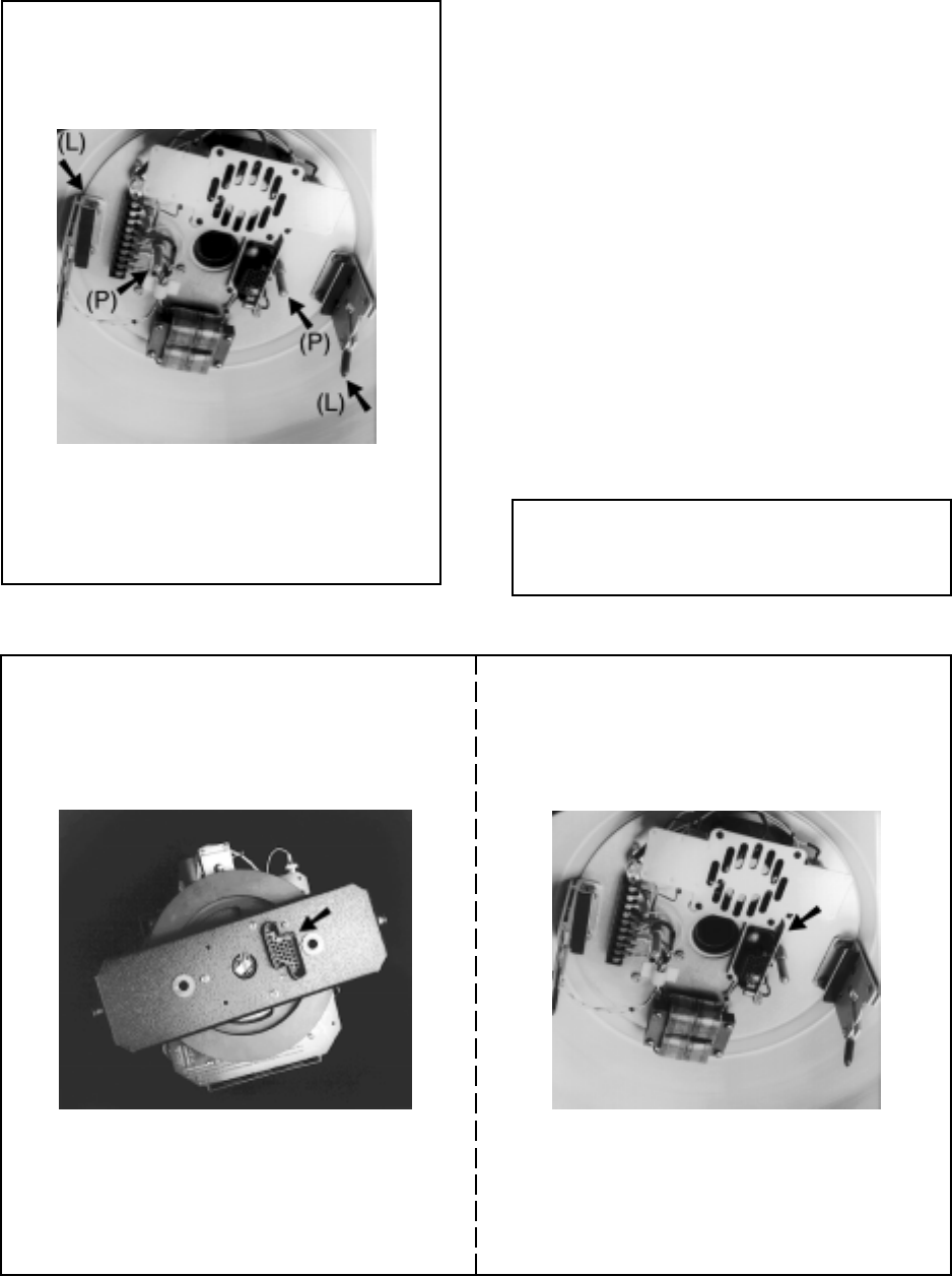
5. While lifting the unit up into the back box, find the
two (2) V-opening latches and two (2) guide pins
at the rear of the back box (see Figure 5).
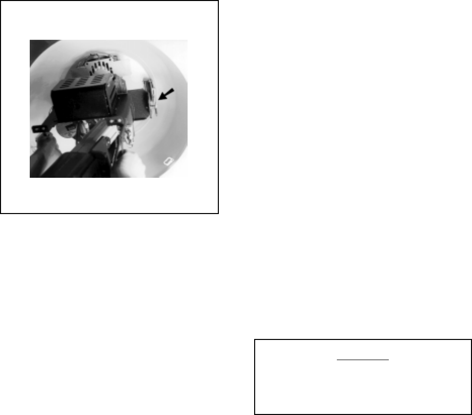
NOTE: Ensure that you install the fixed mount
in correct rotation to the back box so that the
electrical connector on top of fixed mount lines
up with mating connector in back box (see Fig-
ure 6).
6. Upon locating the guide pins, wiggle the unit back
and forth to ensure the guide pins are aligned with
the two (2) Delrin bushings on the fixed mount. At
that instant, push the mount up until the two (2) V-
shaped latches engage and lock the mount in place
(see Figure 7). Be sure the latches are completely
closed by pulling down on the latch arm as a check.
7. Insert the two hairpin style safety pins previously
removed in step 2 into the latches to prevent inad-
vertent release of fixed mount from the back box.
8. Install camera/lens of choice, positioning onto
mount with sufficient clearance for dome attach-
ment.
9. Remove lens cap.
10. Install dome onto fixed mount (refer to Figure 3),
aligning window slot of dome with lens.
NOTE: The fixed mount may also be in-
stalled/removed (or bicycled) with the camera/
lens already installed on mount, if needed.
4 PELCO Manual C290M-A (6/99)
Figure 2. Removing Safety Pins
Figure 1. Back Box Power Switch Location Figure 3. Removing/Attaching Dome to Fixed
Mount
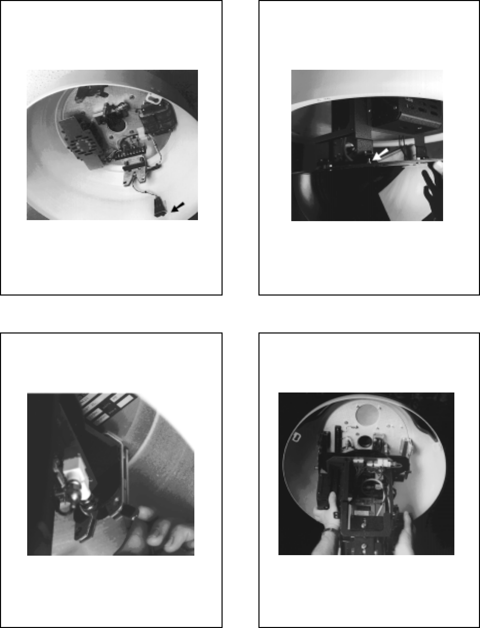
Figure 4. Installing Fixed Mount
PELCO Manual C290M-A (6/99) 5
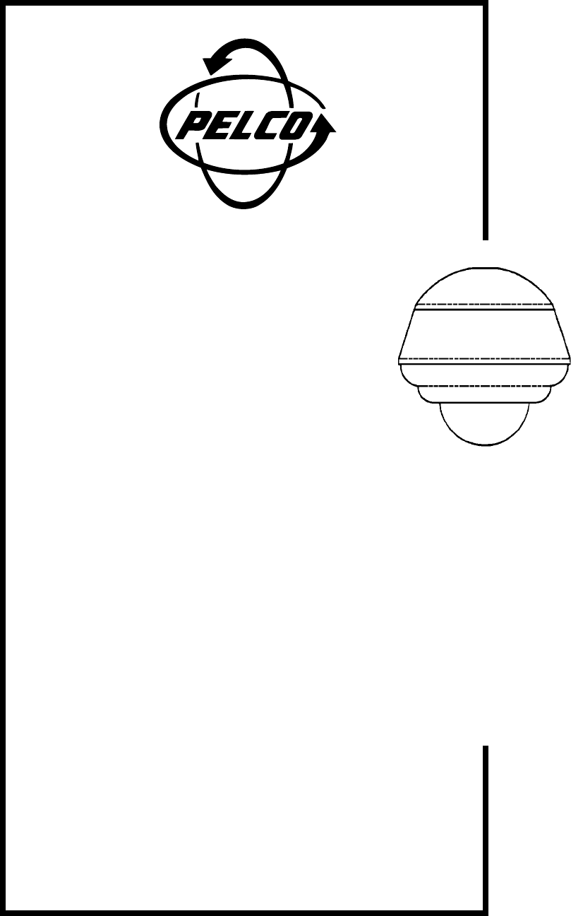
Figure 6. Fixed Mount/Back Box Electrical Interconnect
Fixed Mount Electrical Connector Back Box Mating Connector
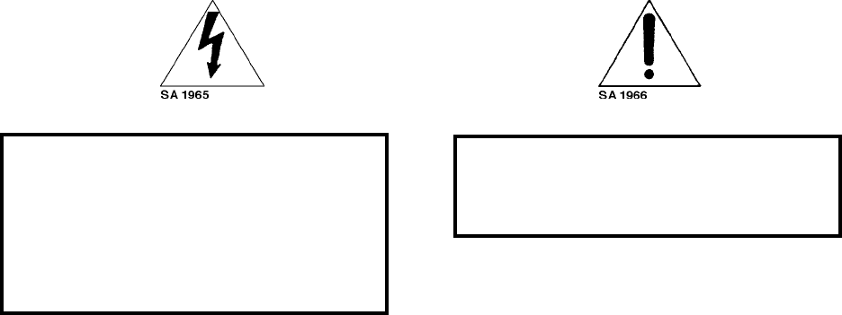
Figure 5. Guide Pin/Latch Locations
L = Latch
P = Pin
4.1.2 REMOVING FIXED MOUNT
To remove the fixed mount:
1. Remove the back box bezel/trim ring as described
in back box manual, C456M, and the dome.
2. Turn off back box power switch, if applicable to
your model (see Figure 1).
3. Remove the two hairpin style safety pins from the
back box latches (see Figure 2).
4. Open only one of the latches by pressing the latch
arm with your finger.
5. Grasp the unit with one hand to prepare for the 5-
10 lb (2.27-4.54 kg) load. Now press open the other
latch with your other hand and lower the fixed
mount.
NOTE: When handling the mount please treat
it with care for there are components that could
possibly bend or be damaged.
6 PELCO Manual C290M-A (6/99)
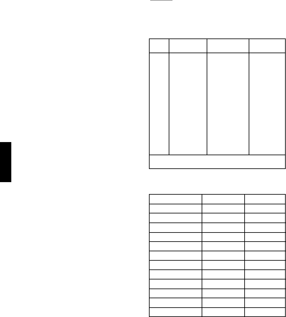
Figure 7. Locking Fixed Mount in Place
5.0 ADJUSTMENTS
To adjust the horizontal and vertical position of the
fixed mount perform the following steps:
1. Remove dome as per instructions in Section 4.1.1,
step 3.
2. Loosen the horizontal positioning lock-down knob;
then rotate mount to the desired position and re-
tighten knob.
3. Loosen the vertical positioning lock-down knob
and adjust tilt table to desired position; then re-
tighten knob.
4. Attach the dome to the drive as described in Sec-
tion 4.3, step 3, Camera/Lens Installation.
5.1 OPERATION
Upon completion of the fixed mount and camera/lens
installation and positioning adjustments of the fixed
mount, the Intercept Dome is ready for operation.
Reach into the back box and turn the power switch ON
(if applicable to your back box).
CAUTION
The fixed mount should never be installed
or removed when power switch is in the
ON position.
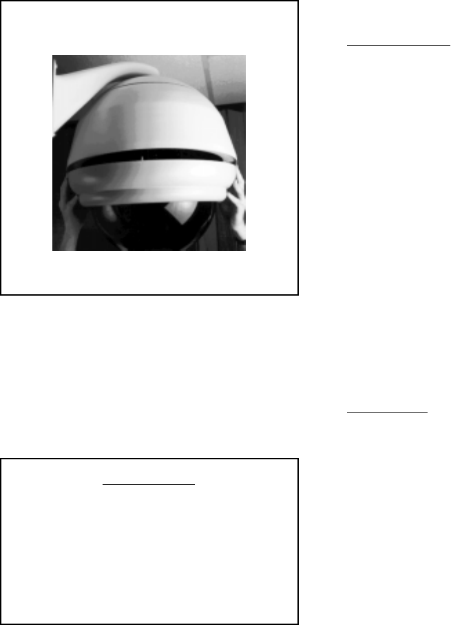
Now attach the bezel or trim ring to the back box as
shown in Figure 8. Align the three bezel pins with the
large hole in the back box brackets; push the bezel up
and rotate clockwise to latch.
Installation of your Intercept Dome is now complete
and dome is ready for operation.
4.2 LENS WIRING
Refer to back box manual, C456M, for wiring pinouts
and wire lens according to manufacturers instructions .
4.3 CAMERA/LENS INSTALLATION
Install the camera/lens you have selected for use with
the IDS08 series dome as follows:
1. Attach camera/lens to the tilt table using the 1/4-
20 x 1/2" fastener (supplied), mounting through
the tilt table into the camera. Only snug the fas-
tener at this time to allow for camera/lens posi-
tioning.
2. Connect camera power spade lugs and coax video
cable.
3. Ensure there is sufficient initial clearance between
the camera/lens and dome as you carefully attach
dome to fixed mount. Align the two (2) ball studs
on the dome to the two (2) ball stud receivers on
the fixed mount and push dome until a snapping
sound occurs (refer to Figure 3).
4. Position camera/lens and route wiring as neces-
sary to achieve clearances. This procedure may re-
quire removing and reattaching dome a few times
to obtain correct position.
5. After satisfactory clearances have been achieved,
remove dome and tighten camera/lens fastener.
PELCO Manual C290M-A (6/99) 7
Figure 8. Bezel Attachment
6.0 CARE AND MAINTENANCE
Regularly scheduled maintenance will prolong the op-
erational life and appearance of the equipment.
IMPORTANT
The acrylic dome is an optical surface.
When cleaning the inner surface of the
dome and viewing window, treat as care-
fully as you would a fine camera lens.
Do not use liquid of any kind on
coated inner surface of dome.
If dust or other debris accumulates on the inside of the
lower dome, remove with clean air pressure only. Com-
pressed air cans are available from commercial photo-
graphic equipment and supply dealers.
Clean the outer surface of the dome and the inner
surface of the viewing window with a non-abra-
sive cleaning cloth and anti-static cleaner that is safe for
use on acrylic plastic. Do not use kerosene or similar
substances that can scratch the surface.
7.0 SPECIFICATIONS
MECHANICAL
Pan: 360° movement in horizontal plane
Tilt: -90° movement from horizontal
plane
Approximate
Camera/Lens
Size: Maximum total length of camera/
lens 6.50" (16.5 cm), including
BNC cable connection to camera;
max. lens width 4.50" (11.4 cm);
max. lens height 3.25" (8.25 cm)
Connectors
Video: BNC
Camera Power: Spade lugs
GENERAL
Construction
Fixed Mount: Aluminum with stainless steel
hardware
Lower Dome: Acrylic hemisphere available in
the following types:
Black opaque with smoked win-
dow (1 f-stop light loss)
Black opaque with clear window
(virtually zero light loss)
Chrome or Gold (2 f-stop light
loss)
Weight: 2 lbs 4.8 oz. (1.04 kg).
8 PELCO Manual C290M-A (6/99)
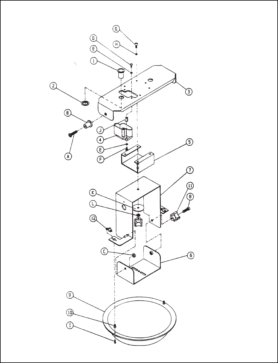
8.0 EXPLODED ASSEMBLY DIAGRAM
Figure 9. DD08 Fixed Mount Exploded Assembly Diagram

PELCO Manual C290M-A (6/99) 9
8.1 MECHANICAL PARTS LIST
The following parts list corresponds to the exploded assembly diagram in Figure 9.
Item No. Quantity Description Part Number
1 2 Bushing, delrin 3/8" ID x 5/8" OD 80010004
2 2 Push nut, .625" OD 80010011
3 1 Bracket, drive mount, upper 8004034COMP
4 1 Connector, receptacle, 25 position CON10J025Z41T
5 1 Bracket, spindle, fixed mount 8004037COMP
6 1 Tilt table, fixed mount 8004021COMP
7 1 Frame 8", fixed mount 8004022COMP
8 2 Pin, latch, dome drive 8004145COMP
9 1 Dome, 8-1/2", acrylic
Black opaque w/smoked viewing window 80810011-0
Black opaque w/clear viewing window 80810011-1
Chrome finish f/2 80810011-2
Gold finish f/2 80810011-3
10 2 Ball stud PT180410000
11 2 Knob, grey, 1/4-20 tapped CM1610003
12 2 Receiver, ball stud PT180410001
13 6 Pin, crimp, loose piece (not shown) CON66107-2
(for use with item #4)
14 1 Connector, BNC, crimp, for RG174 coax CONCPM88-174
(not shown)
8.2 ASSOCIATED HARDWARE
Item No. Quantity Description Part Number
A 2 Screw 1/4-20 x 1" flat hd phil, SS ZH1/420X1.00SFS
B 1 Screw 1/4-20 x 1" soc hd c/s,SS ZH1/420X1.00SS
C 1 Nut, lock, hex, 1/4-20, nylon insert, SS ZH1/420NUTCHN
D 2 Screw 6-32 x 3/8" pan hd phil, SS ZH6-32X.375SPP
E 4 Washer, internal star #6, SS ZH6LWSIS
F 2 Screw 6-32 x 1/2" pan hd phil, SS ZH6-32X.500SPP
G 4 Screw 8-32 x 1/2" pan hd phil, SS ZH8-32X.500SPP
H 4 Washer, internal star #8, SS ZH8LWSIS
I 2 Screw 6-32 x 3/8" flat hd phil, black oxide ZH6-32X.375BPF
J 2 Spacer, 1/4" hex x 1/2" L, 6-32 tapped SPA8423
K 1 Washer, fender, 1/4 x 1.5 x 14 ga, black oxide ZH255X1.50X62
L 1 Washer, split lock, 1/4" SS ZH1/4LWSSL

10 PELCO Manual C290M-A (6/99)
9.0 WARRANTY AND RETURN
INFORMATION
WARRANTY
Pelco will repair or replace, without charge, any merchandise proved defective in material
or workmanship for a period of one year after the date of shipment.
Exceptions to this warranty are as noted below:
• Five years on FT/FR8000 Series fiber optic products.
• Three years on Genex® Series products (multiplexers, server, and keyboard).
• Three years on Camclosure® and fixed camera models, except the CC3701H-2,
CC3701H-2X, CC3751H-2, CC3651H-2X, MC3651H-2, and MC3651H-2X camera
models, which have a five-year warranty.
• Two years on standard motorized or fixed focal length lenses.
• Two years on Legacy®, CM6700/CM6800/CM9700 Series matrix, and DF5/DF8 Series
fixed dome products.
• Two years on Spectra®, Esprit®, ExSite™, and PS20 scanners, including when used in
continuous motion applications.
• Two years on Esprit® and WW5700 Series window wiper (excluding wiper blades).
• Eighteen months on DX Series digital video recorders, NVR300 Series network video
recorders, and Endura™ Series distributed network-based video products.months on DX
Series digital video recorders, NVR300 Series network video recorders, Endura™ Series
distributed network-based video products, and TW3000 Series twisted pair transmission
products.
• One year (except video heads) on video cassette recorders (VCRs). Video heads will be
covered for a period of six months.
• Six months on all pan and tilts, scanners or preset lenses used in continuous motion
applications (that is, preset scan, tour and auto scan modes).
Pelco will warrant all replacement parts and repairs for 90 days from the date of Pelco
shipment. All goods requiring warranty repair shall be sent freight prepaid to Pelco, Clovis,
California. Repairs made necessary by reason of misuse, alteration, normal wear, or
accident are not covered under this warranty.
Pelco assumes no risk and shall be subject to no liability for damages or loss resulting
from the specific use or application made of the Products. Pelco’s liability for any claim,
whether based on breach of contract, negligence, infringement of any rights of any party
or product liability, relating to the Products shall not exceed the price paid by the Dealer to
Pelco for such Products. In no event will Pelco be liable for any special, incidental or
consequential damages (including loss of use, loss of profit and claims of third parties)
however caused, whether by the negligence of Pelco or otherwise.
The above warranty provides the Dealer with specific legal rights. The Dealer may also
have additional rights, which are subject to variation from state to state.
If a warranty repair is required, the Dealer must contact Pelco at (800) 289-9100 or
(559) 292-1981 to obtain a Repair Authorization number (RA), and provide the following
information:
1. Model and serial number
2. Date of shipment, P.O. number, Sales Order number, or Pelco invoice number
3. Details of the defect or problem
If there is a dispute regarding the warranty of a product which does not fall under the
warranty conditions stated above, please include a written explanation with the product
when returned.
Method of return shipment shall be the same or equal to the method by which the item
was received by Pelco.
RETURNS
In order to expedite parts returned to the factory for repair or credit, please call the factory
at (800) 289-9100 or (559) 292-1981 to obtain an authorization number (CA number if
returned for credit, and RA number if returned for repair).
All merchandise returned for credit may be subject to a 20% restocking and refurbishing
charge.
Goods returned for repair or credit should be clearly identified with the assigned CA or RA
number and freight should be prepaid. Ship to the appropriate address below.
If you are located within the continental U.S., Alaska, Hawaii or Puerto Rico, send goods
to: Service Department
Pelco
3500 Pelco Way
Clovis, CA 93612-5699
If you are located outside the continental U.S., Alaska, Hawaii or Puerto Rico and are
instructed to return goods to the USA, you may do one of the following:
If the goods are to be sent by a COURIER SERVICE, send the goods to:
Pelco
3500 Pelco Way
Clovis, CA 93612-5699 USA
If the goods are to be sent by a FREIGHT FORWARDER, send the goods to:
Pelco c/o Expeditors
473 Eccles Avenue
South San Francisco, CA 94080 USA
Phone: 650-737-1700
Fax: 650-737-0933
WARRANTY AND RETURN INFORMATION
® Pelco, the Pelco logo, Spectra, Esprit, Genex, Legacy, and Camclosure are registered trademarks of Pelco.
™ Endura and ExSite are trademarks of Pelco. © Copyright 1999, Pelco. All rights reserved.
