Pentair Aquatic Systems EASYTOUCH Easy Touch Wireless User Manual EasYTouch Wireless Control Panel Preliminary
Pentair Aquatic Systems Easy Touch Wireless EasYTouch Wireless Control Panel Preliminary
UserManual.wiki
>
Pentair Aquatic Systems
>
EASYTOUCH User Manual
User Manual
Navigation menu
Upload a User Manual
Namespaces
Wiki Guide
HTML
PDF
Info
Views
User Manual
Discussion / Help
Navigation

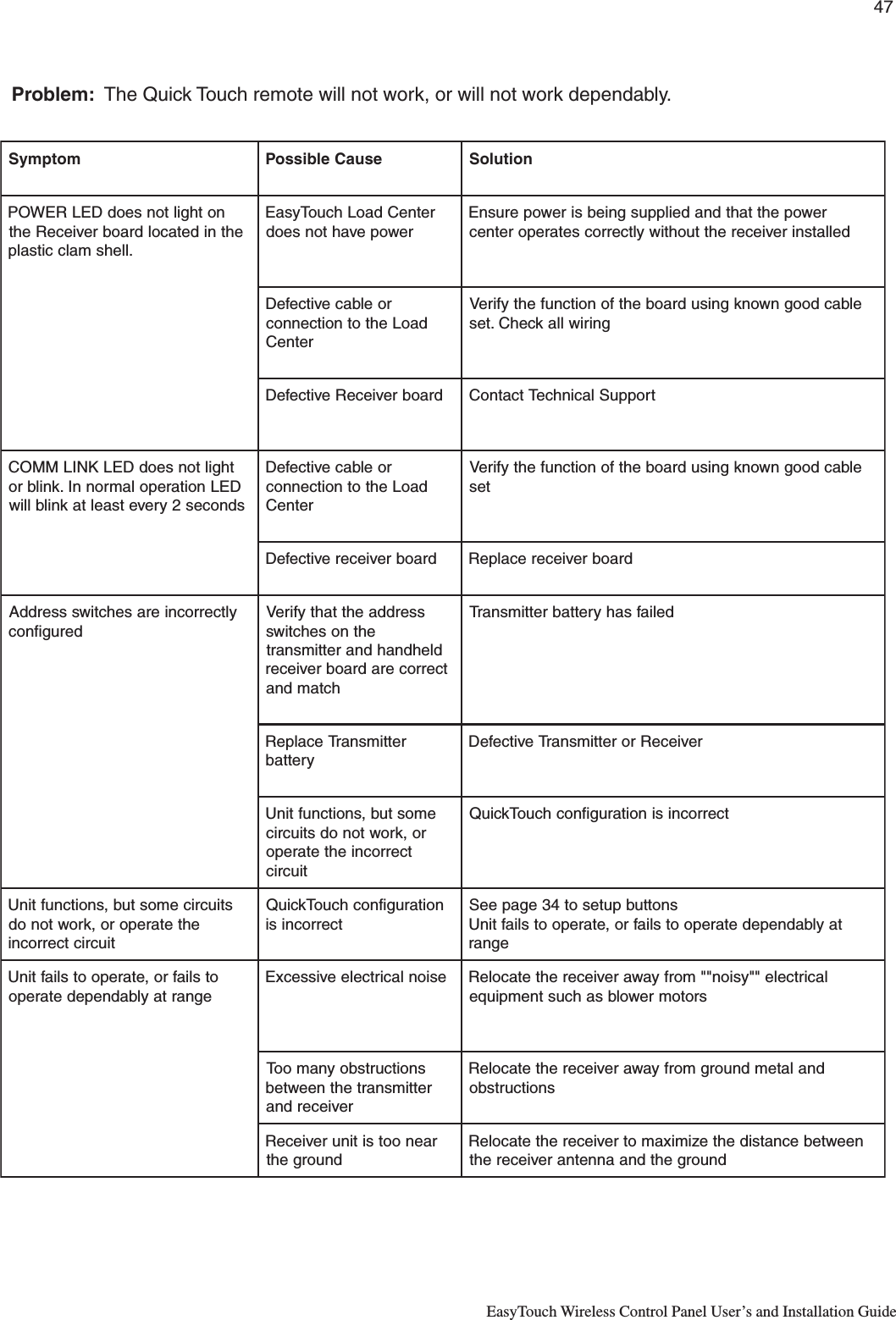
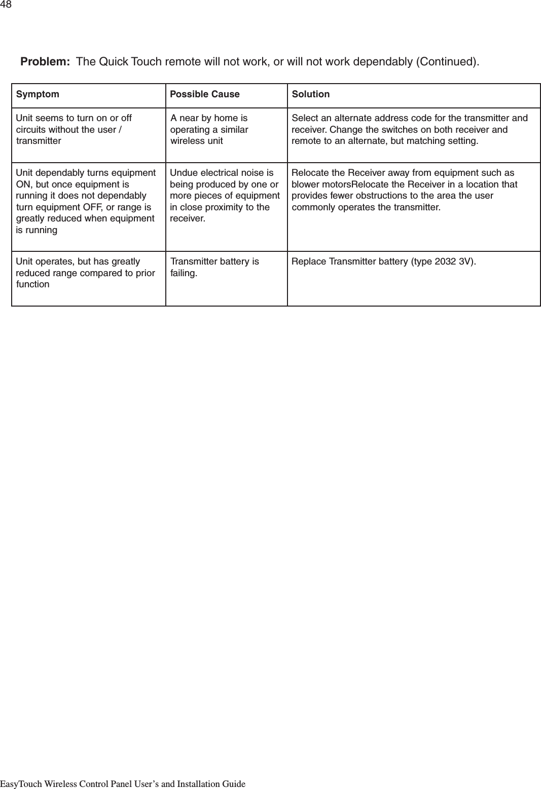
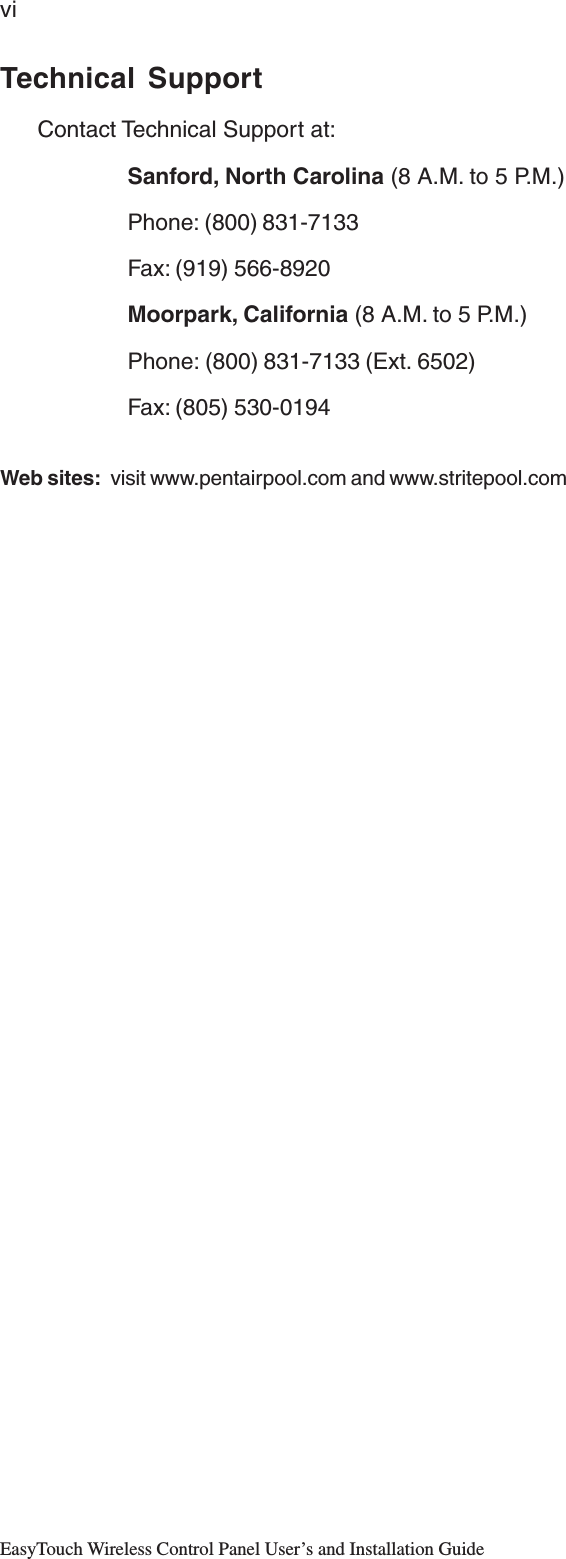
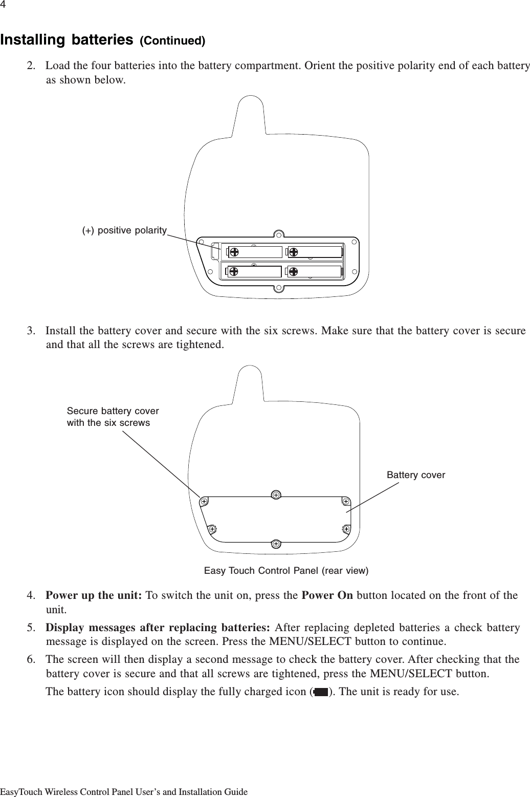
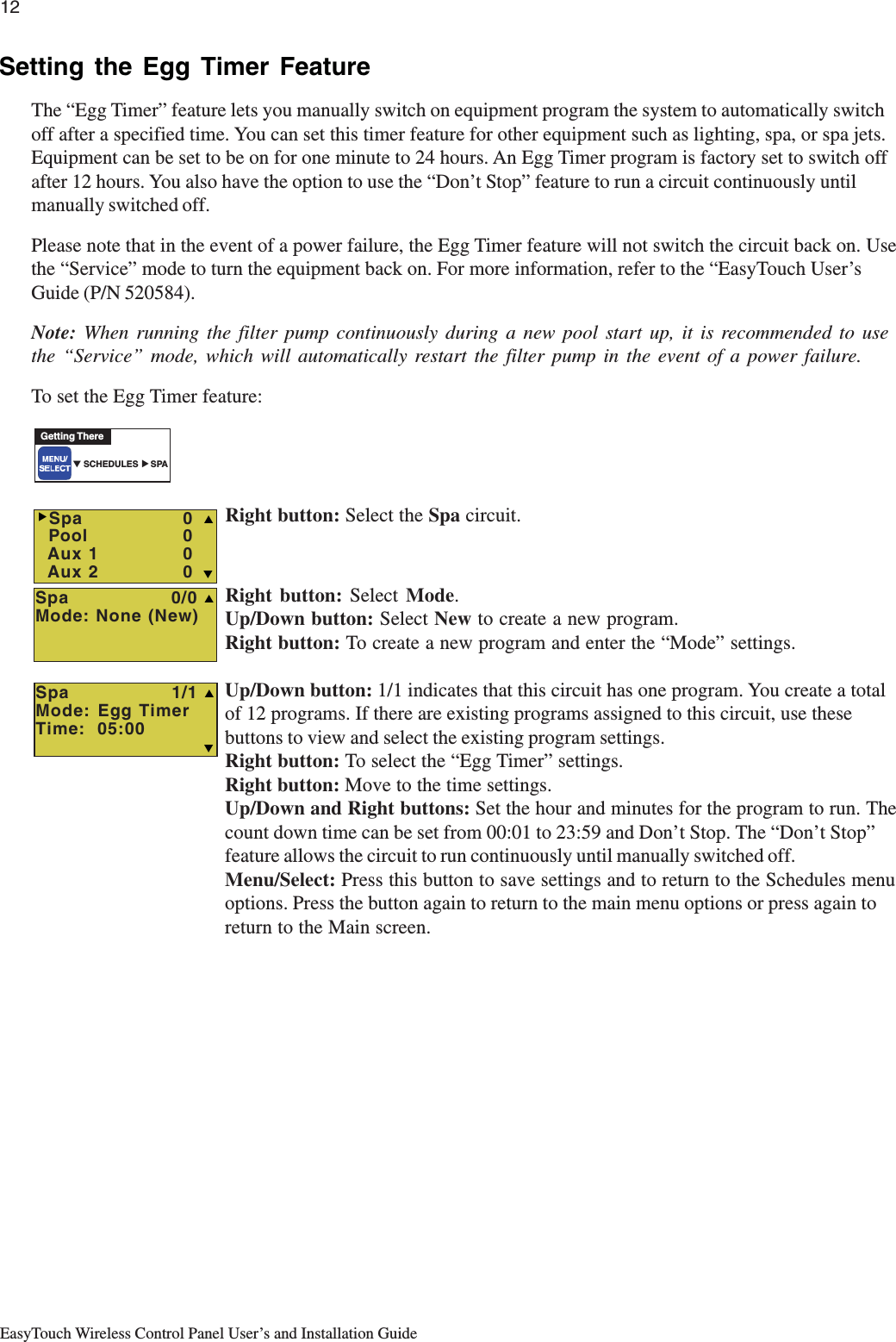
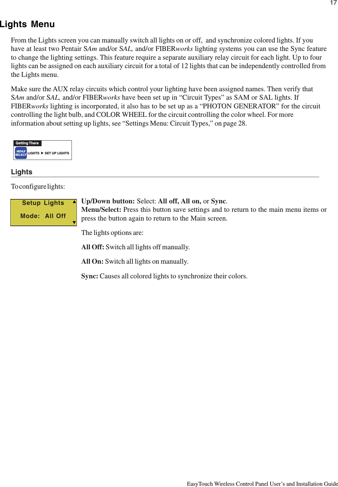
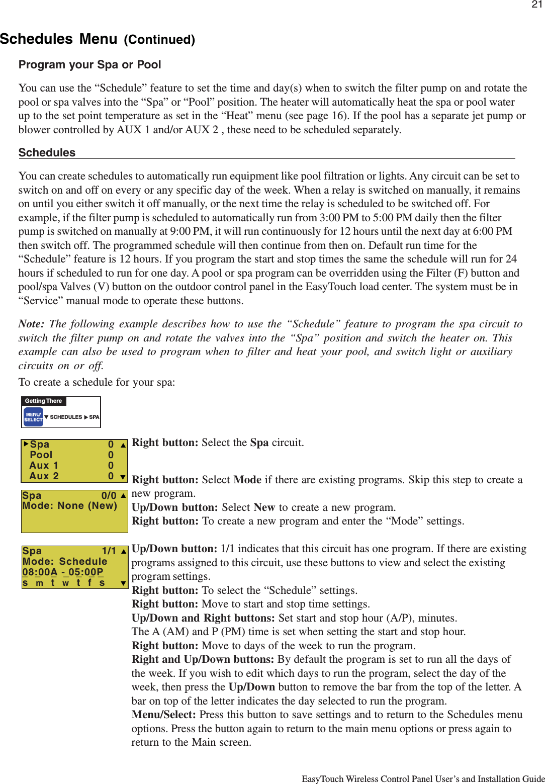
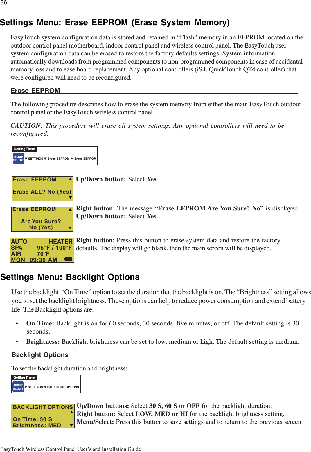
![iiEasyTouch Wireless Control Panel User’s and Installation GuideSection 2: EasyTouch Menus (Continued)Settings Menu: Custom Names .................................................................................................... 30Settings Menu: Valves .................................................................................................................. 30Settings Menu: 2-Speed Pump .....................................................................................................31Settings Menu: Solar .................................................................................................................... 31Settings Menu: Delays ................................................................................................................. 32Settings Menu: F° / C° (Celsius/Fahrenheit) ................................................................................. 33Settings Menu: iS4 Spa-Side Remote Controller ........................................................................... 33Settings Menu: QuickTouch (QT4) Wireless Remote .................................................................... 34Settings Menu: Man Heat (Off/On) ................................................................................................35Settings Menu: Calibration ........................................................................................................... 35Settings Menu: Erase EEPROM (Erase System Memory) ........................................................... 36Settings Menu: Backlight Options ................................................................................................36Settings Menu: Power Save Options ............................................................................................ 37Spa Side [On/Off] ......................................................................................................................... 37Diagnostics Menu: Software Rev .................................................................................................. 38Diagnostics Menu: Bootloader Rev ............................................................................................... 38Diagnostics Menu: Self Test ......................................................................................................... 38Diagnostics Menu: Chlorinator ...................................................................................................... 39Diagnostics Menu: Water Temp ....................................................................................................39Diagnostics Menu: Solar Temp ..................................................................................................... 39Diagnostics Menu: Air Temp ......................................................................................................... 40Diagnostics Menu: Disp Codes ....................................................................................................40Diagnostics Menu: Cir Names: [Off/On] ........................................................................................ 40Diagnostics Menu: Reset System ................................................................................................ 40Diagnostics Menu: Flash Update ..................................................................................................41Power OFF ................................................................................................................................... 41Section 3: Troubleshooting ........................................................................................................... 43Troubleshooting ................................................................................................................................43Frequently Asked Questions (FAQ) .................................................................................................. 43How do I setup a two-speed pump? .................................................................................................. 43Can I switch the heater on and change the temperature from the spa? ............................................. 43How do I switch on solar heating? .................................................................................................... 43EasyTouch Error Messages ............................................................................................................. 44Self Test Error Codes ....................................................................................................................... 44Maximum Programs Exceeded ........................................................................................................ 45IntelliChlor Error Messages .............................................................................................................. 45System Problem Diagnosis .............................................................................................................. 46Problem: iS4 fails to operate. ........................................................................................................... 46Problem: The Quick Touch remote will not work, or will not work dependably ................................... 47Section 4: EasyTouch Transceiver Module Installation .............................................................. 45Installing the EasyTouch Transceiver Module .................................................................................... 49EasyTouch wireless control panel kit ................................................................................................ 49Mounting the EasyTouch Transceiver Module ................................................................................... 49Connecting the EasyTouch Transceiver to the Load Center ............................................................... 51Glossary of Terms .......................................................................................................................... 53Contents](https://usermanual.wiki/Pentair-Aquatic-Systems/EASYTOUCH/User-Guide-607198-Page-4.png)

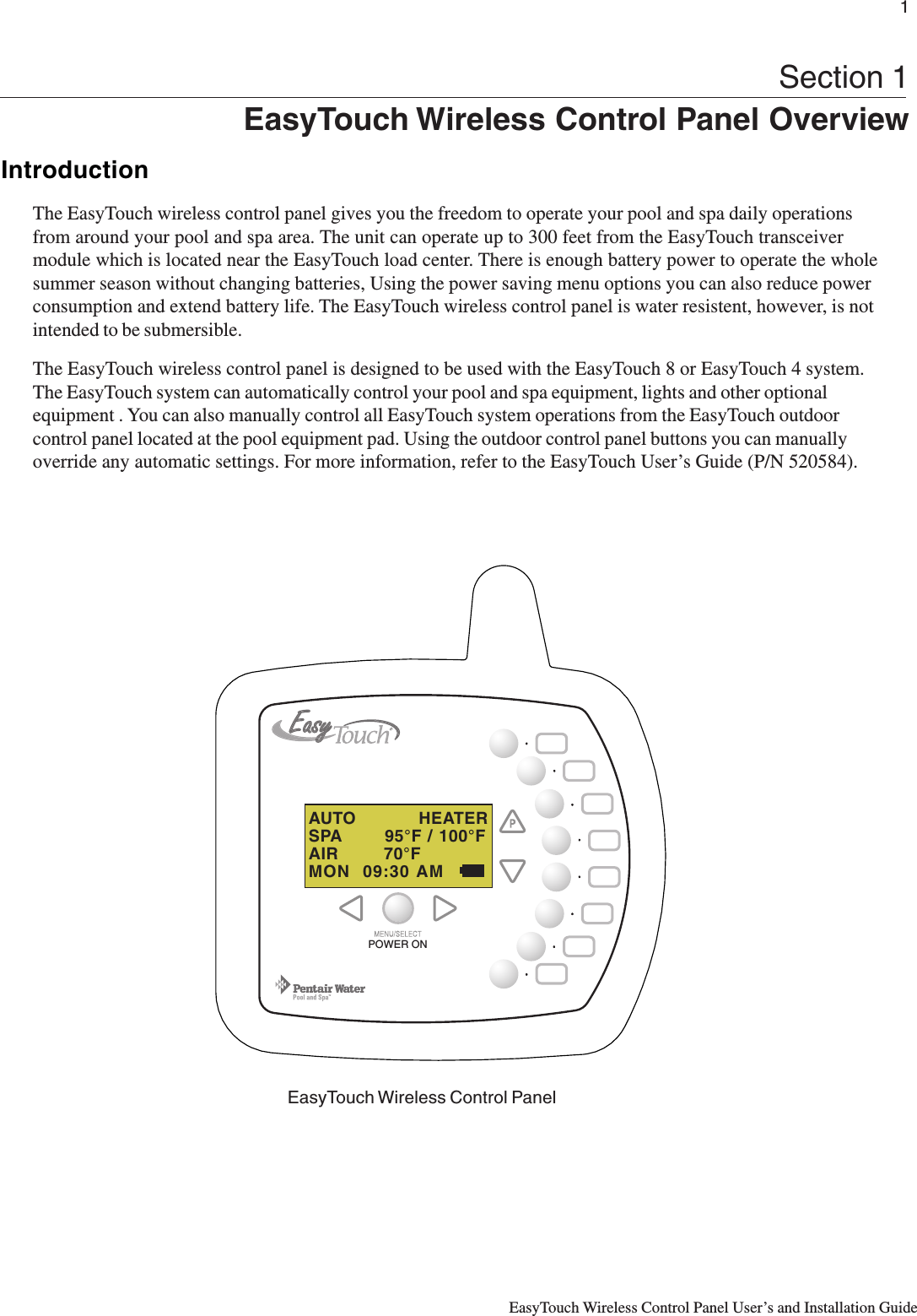
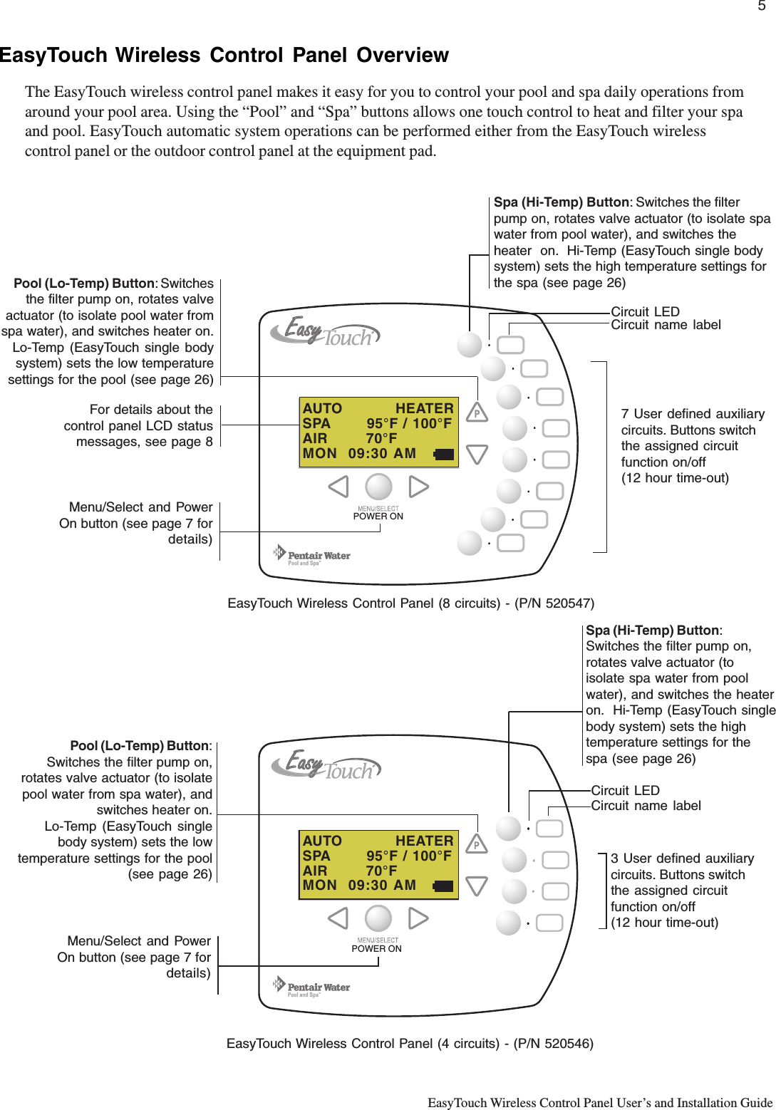
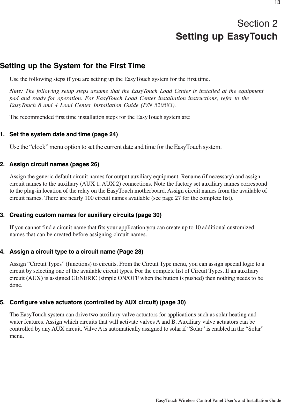
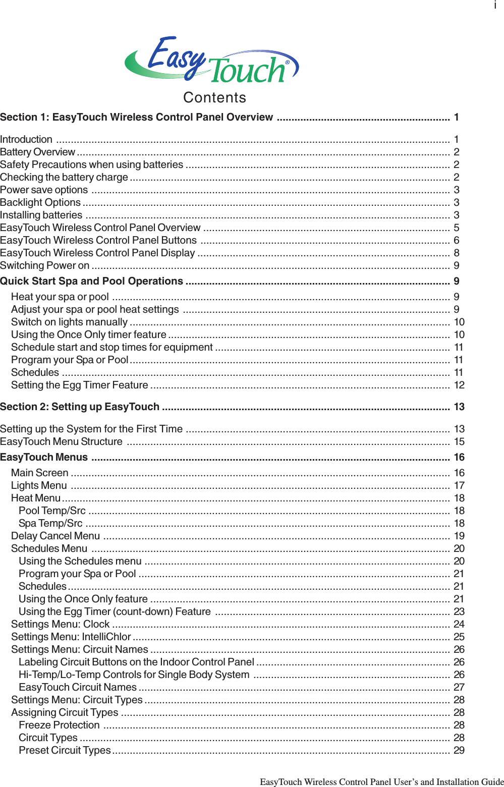
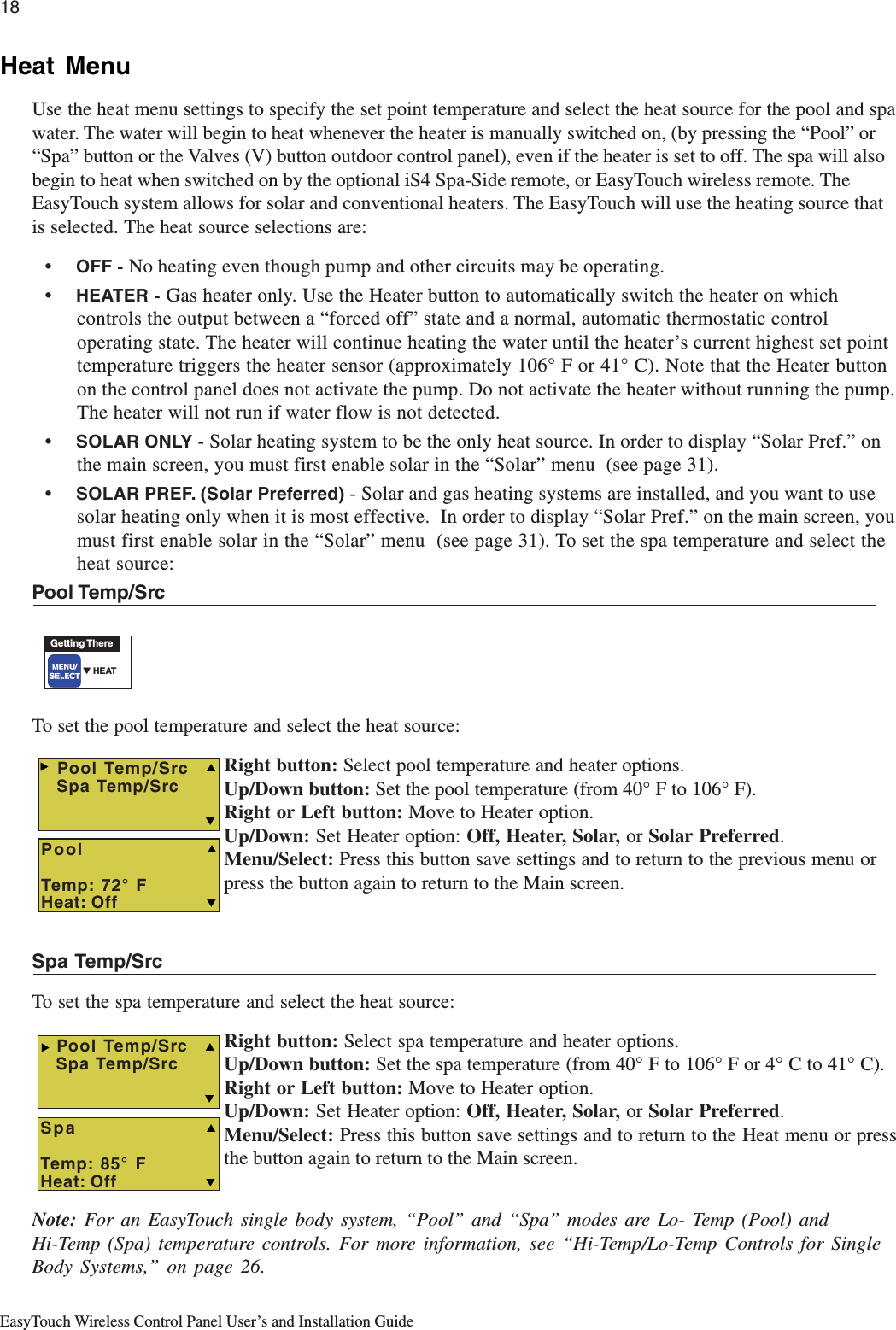
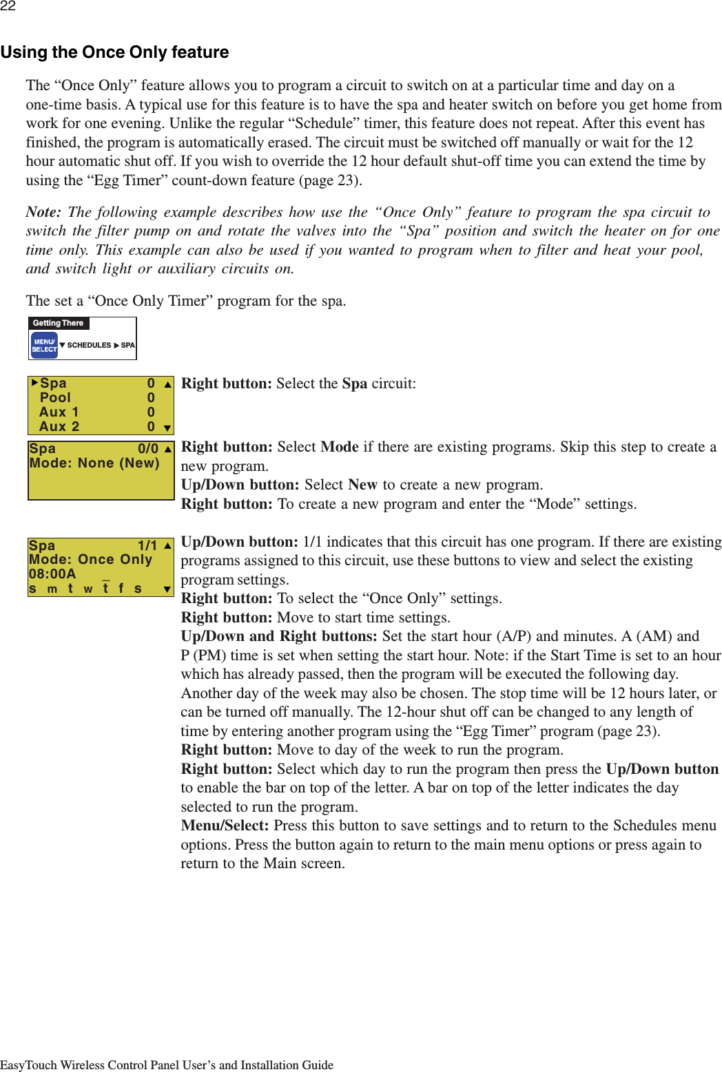
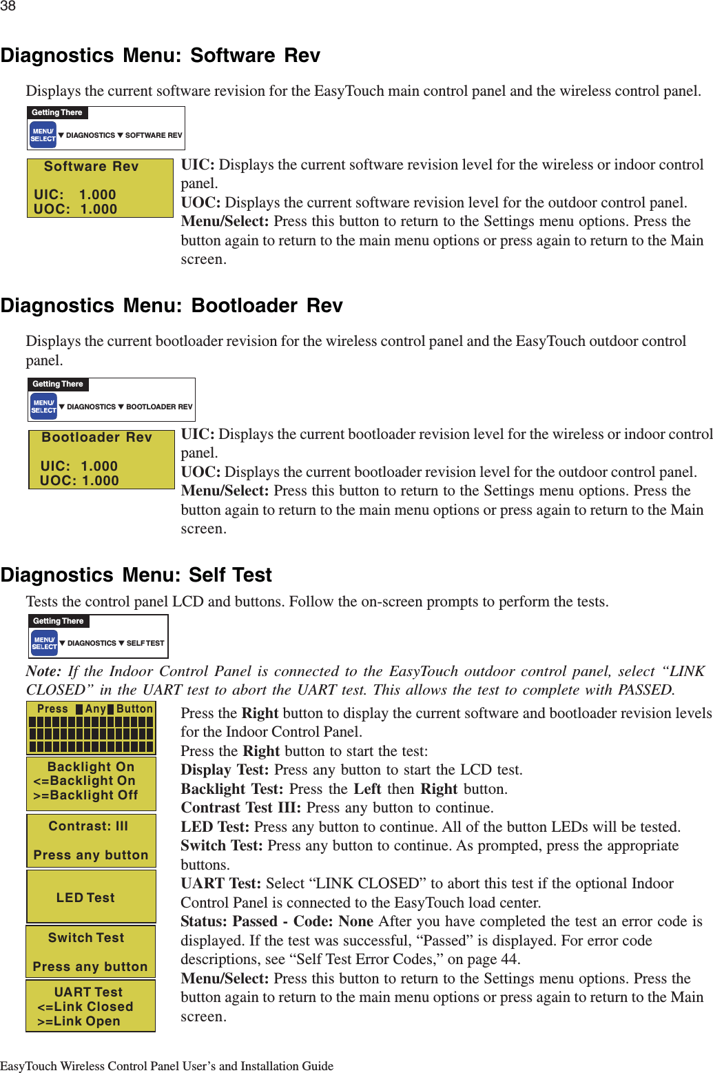
![15EasyTouch Wireless Control Panel User’s and Installation GuideEasyTouch Menu StructureMAIN SCREENAUTO HEATERSPA 100˚ F / 95˚FAIR 70˚FMON 09:30 AMLIGHTS All On (Switch all lights on)All Off (Switch all lights off)Sync (Synchronize colored lights)HEATDIAGNOSTICS Software Rev (Revision level for main control panel and Indoor Control Panel)Bootloader Rev (Revision level for main control panel and Indoor Control Panel)Self Test (Status: Testing (follow on-screen prompts to test LCD and buttons) - Code: 0 - see "Troubleshooting" section for error codes)Water Temp (Fahrenheit/Celcius - Status display only)Solar Temp (Fahrenheit/Celcius - Status display only) - (Displays if Solar is enabled in Heat menu)Air Temp (Fahrenheit/Celcius - Status display only)Pool Temp/Src Temp (40˚ F - 106˚ F) or (4˚ C - 41˚ C)Heat (Off/Heater/Solar/Solar Prf) - Solar/Solar Prf must be enabled in "Solar" menu to display.Spa Temp/Src Temp (40˚ F - 106˚ F) or (4˚ C - 41˚ C)Heat (Off/Heater/Solar/Solar Prf) - "Solar/Solar Prf" must be enabled in "Solar" menu to display.DELAY CANCELMode: Schedule08:00A -- 05:00P (12:00 AM - 11:59 PM -12 hours)s m t w t f s (days of the week) SCHEDULESSPA 0AUX 2 0AUX 4 0AUX 3 0Mode: Egg Timer Time: 12:00 (00:00 - 23:59) / DON'T STOPSETTINGSIntelliChlorEnable (No/Yes)Level (0% - 100%)IntelliChlor 2/2Run Hours (0 -72) IntelliChlor 1/2Super Chlr (On/Off)(Optional) Circuit NamesCircuit (Spa, Pool, AUX 1-3 (ET 4) - Spa, Pool AUX 1 - 7 (ET 8) Refer to "Circuit Names" on page 30Circuit Names 1-9 (Assign names for up to 9 circuits)Circuit Types Circuit (Spa [MASTER SPA], Pool [MASTER POOL], AUX 1-7 (AUX 1-3), Generic, Master Spa, Master Pool, Mstr Cleaner,Freeze: No/YesCustom Names Cstm Name 1/10 (Assign up to 10 custom names) [USERNAME-01...10] (up to 11 alphanumeric characters)2-Speed PumpCircuit (None, Spa, Pool, AUX 1 - 3 (ET 4) - Spa, Pool, AUX 1 - 7 (ET 8), Solar, Heater, Pool Heater, Spa Heater, Freeze) 2-Speed Pmp 1/4 (Assign up to 4 circuits)SolarDelays Pool/Spa (Yes/No) Valves (Yes/No)Enable (Yes/No) Heat Pump (Yes/No)Solar 2/2 (Tempreature Difference)Run (2˚-5˚)Solar 1/2Start (3˚-9˚)ValvesClockF˚ / C˚iS4FAHRENHEIT / CELCIUSQuick Touch Assign QT4 1/4 (Assign up to 4 circuits)Circuit - (None, Spa, Pool, AUX 1 - AUX 7 (ET 8), AUX 1 - AUX 3 (ET 4), HEAT BOOST, HEAT ENABLE) Erase EEPROM Erase all (Yes /No) - Are you sure? (Yes/No)Circuit - (None, Spa, Pool, AUX 1 - AUX 7 (ET 8), AUX 1 - AUX 3 (ET 4), HEAT BOOST, HEAT ENABLE) Assign iS4 1/4 (Assign 4 circuits)CalibrationAir (Fahrenheit/Celcius)Solar (Fahrenheit/Celcius) - Solar must be enabled in "Heat" menu to displayWater (Fahrenheit/Celcius)Date & Time 1/2 June 22 2005 (Month/Day/Year)WED 11:00 AM (Day/Hour/Minutes/AM/PM) Date & Timer 2/2Daylight Saving: (Auto/Manual)Clock Adjust 00:00 (0 to 300) - (-300 to -5) in 5 sceond increments (Delayed Cancelled) Press Right button to activateA: [None, Spa, Pool, AUX 1 - 3 (ET 4) - Spa, Pool, AUX 1 - 7 (ET 8), Heater] - (USED SOLAR if Solar is enabled)B: [None, Spa, Pool, AUX 1 - 3 (ET 4) - Spa, Pool, AUX 1 - 7 (ET 8), Heater]Disp Op Codes - Display? No/Yes (Displays transmit/receive packets numbers on screen)SPA SIDE [Off/On]POOL 0AUX 1 0AUX 5 0 AUX 6 0AUX 7 0Enable/Disable iS4 Spa-Side remote Light, SAM light, SAL Light, Photon Generator, Color Wheel, Spillway, Floor Cleaner (see page 32 for details)Cir Names [On/Off] View default circuit names before modification. Chlorinator Salt Level: Displays current salt level (xxxx) ppmStatus: OK - NO ERRORS (SUPER CHLORINATE, COM LINK ERROR, CHECK FLOW / PCB, LOW SALT, VERY LOW SALT, HIGH CURRENT, CLEAN CELL!!, LOW VOLTAGE)Man Heat [Off/On] Switch manual heat on or off when spa is manually switched on (Use Right button select On/Off)EasyTouch 4EasyTouch 8 Mode: Once Only08:00A (12:00 AM - 11:59 PM -12 hours)s m t w t f s (select day of the week to run program) Mode: New / Delete / NoneReset System (Reinitialize Indoor Control Panel - use Right button)Hi-Temp (Spa) / Lo-Temp (Pool) for single body system (see Settings Menu: Circuit Names) Flash Update (Use for future firmware updates via PC - Press MENU to abort)Power OFF (Manually switch's off the unit - Press the Power ON button to switch unit on)Power Save Options Idle Time: 30 S, 60 S, 5 MBacklight OptionsBrightness: LOW, MED HIOn Time: 30 S, 60 S, OFF](https://usermanual.wiki/Pentair-Aquatic-Systems/EASYTOUCH/User-Guide-607198-Page-23.png)
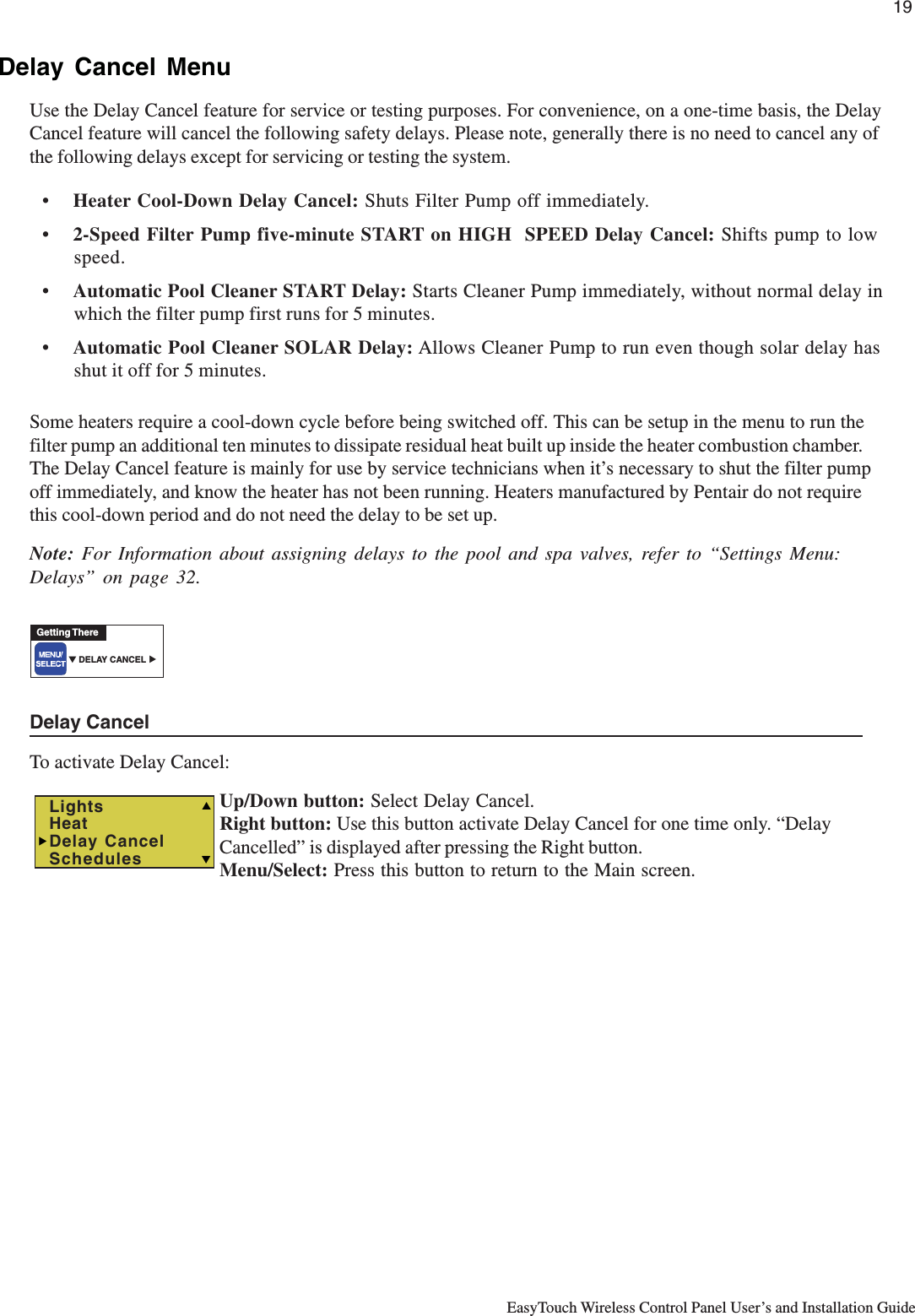
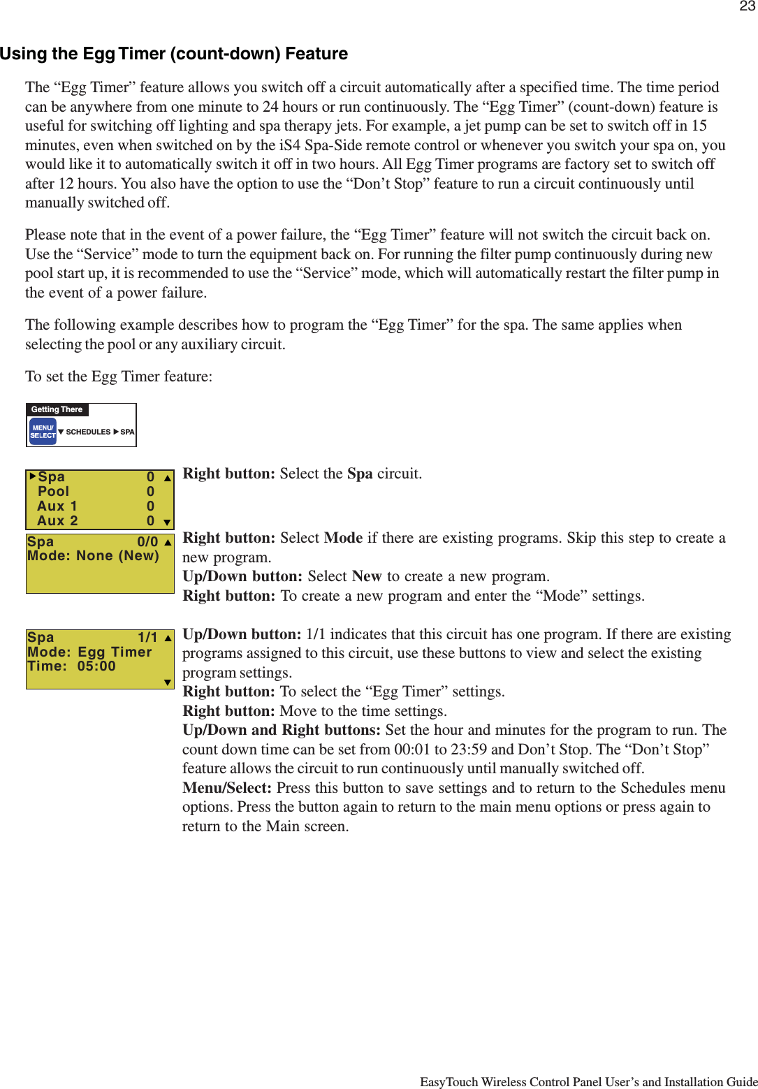
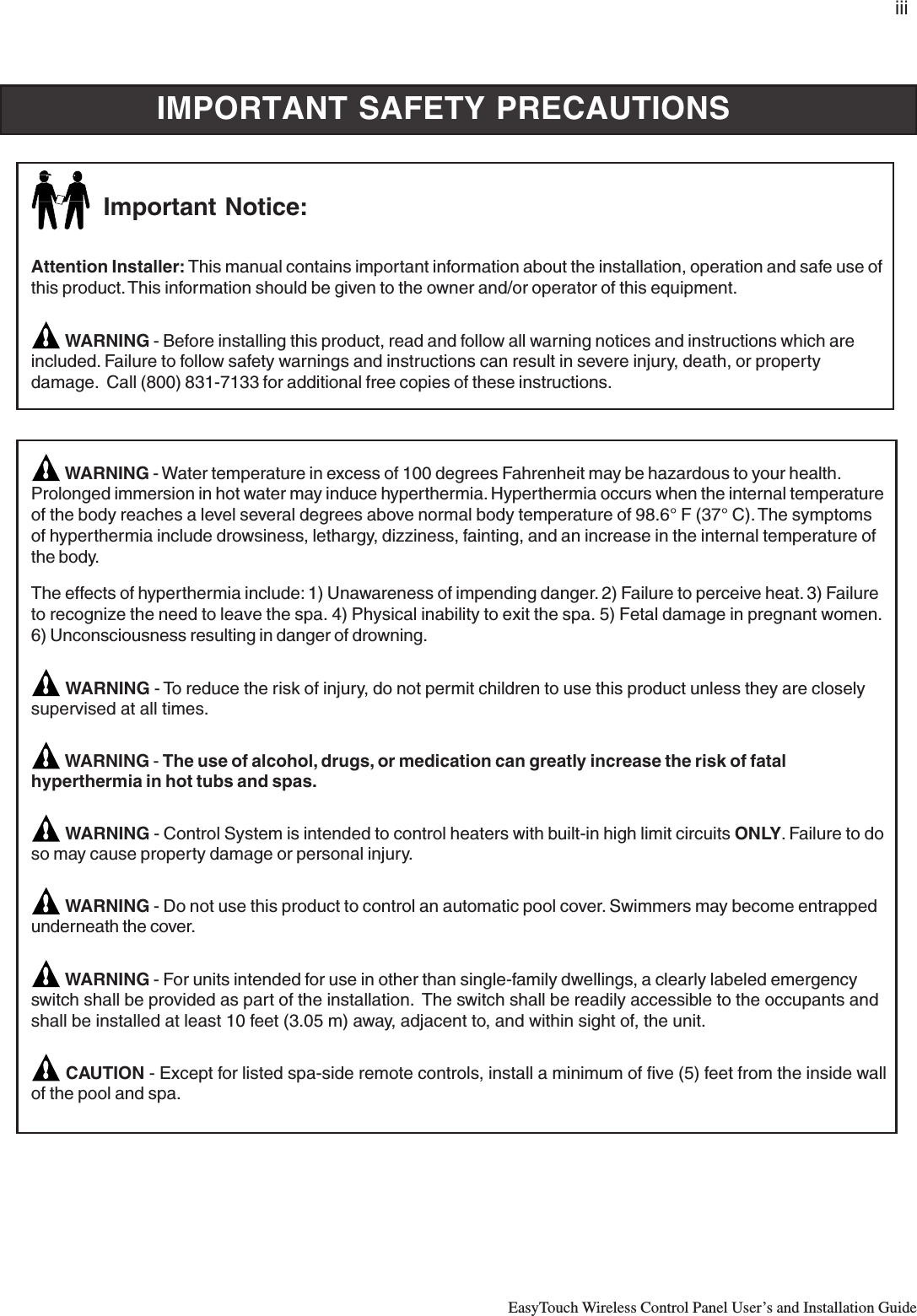
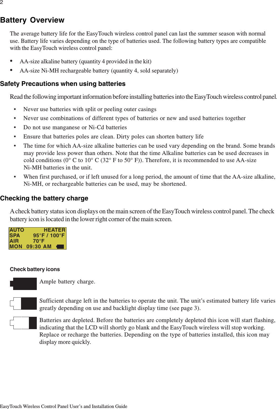
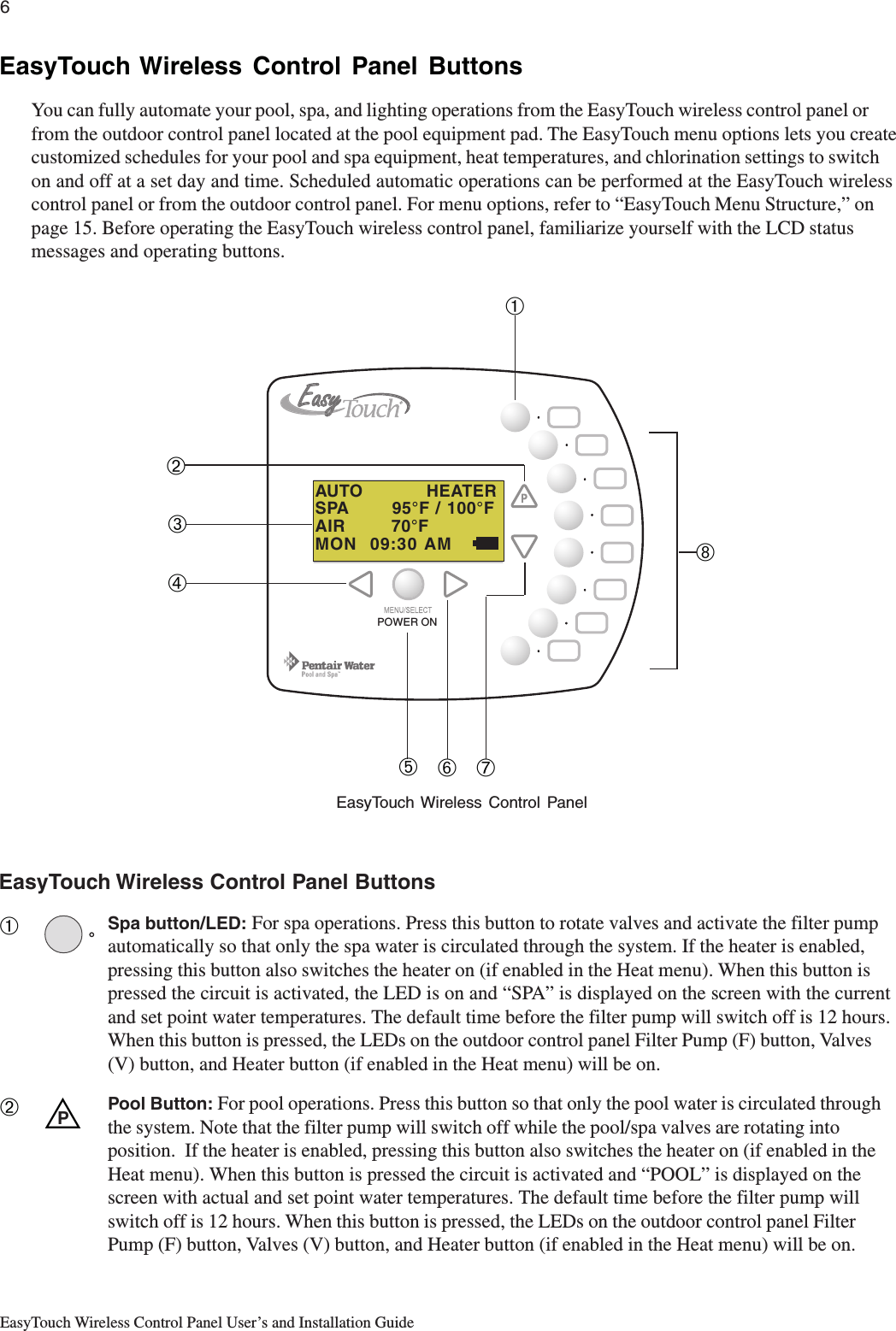
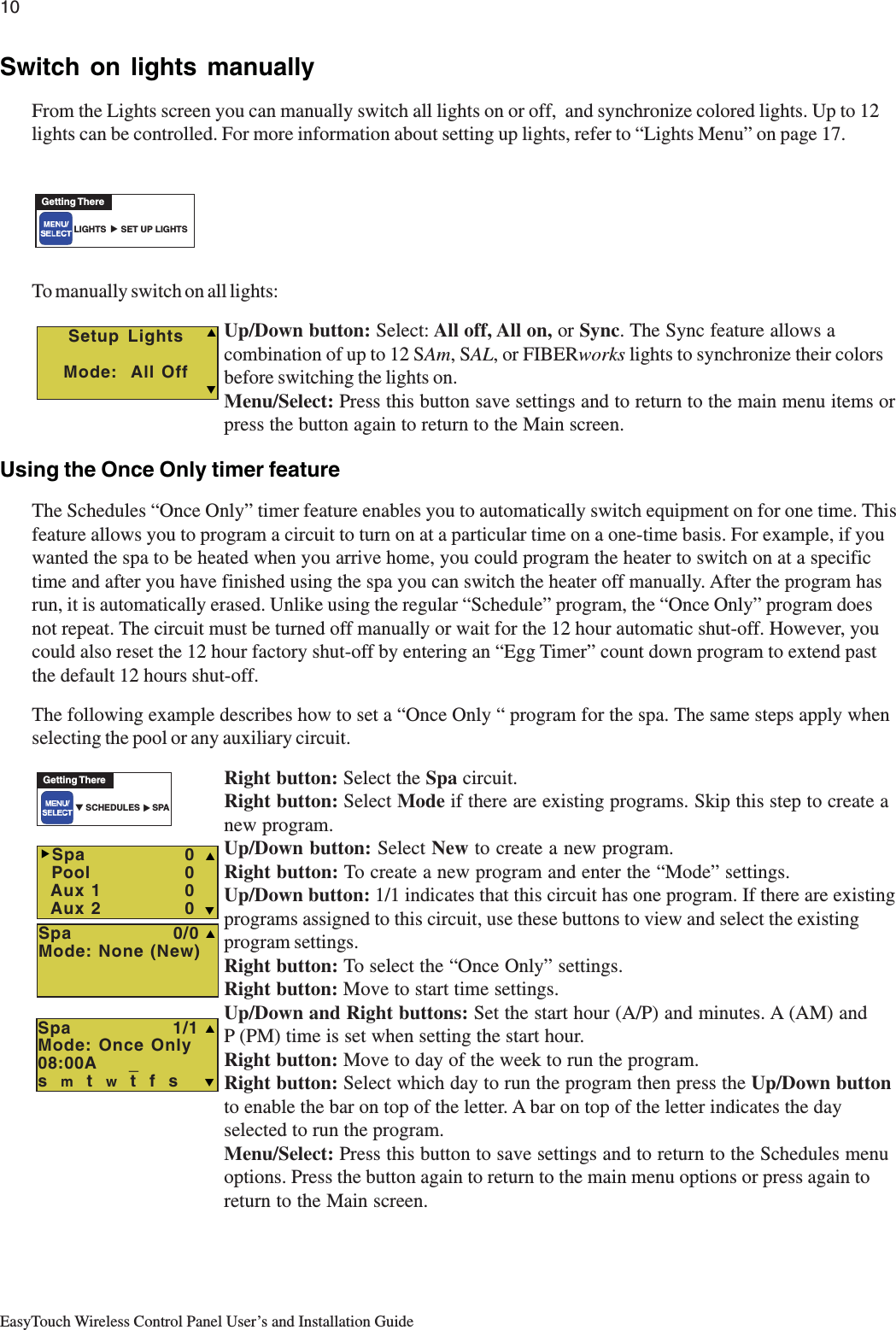
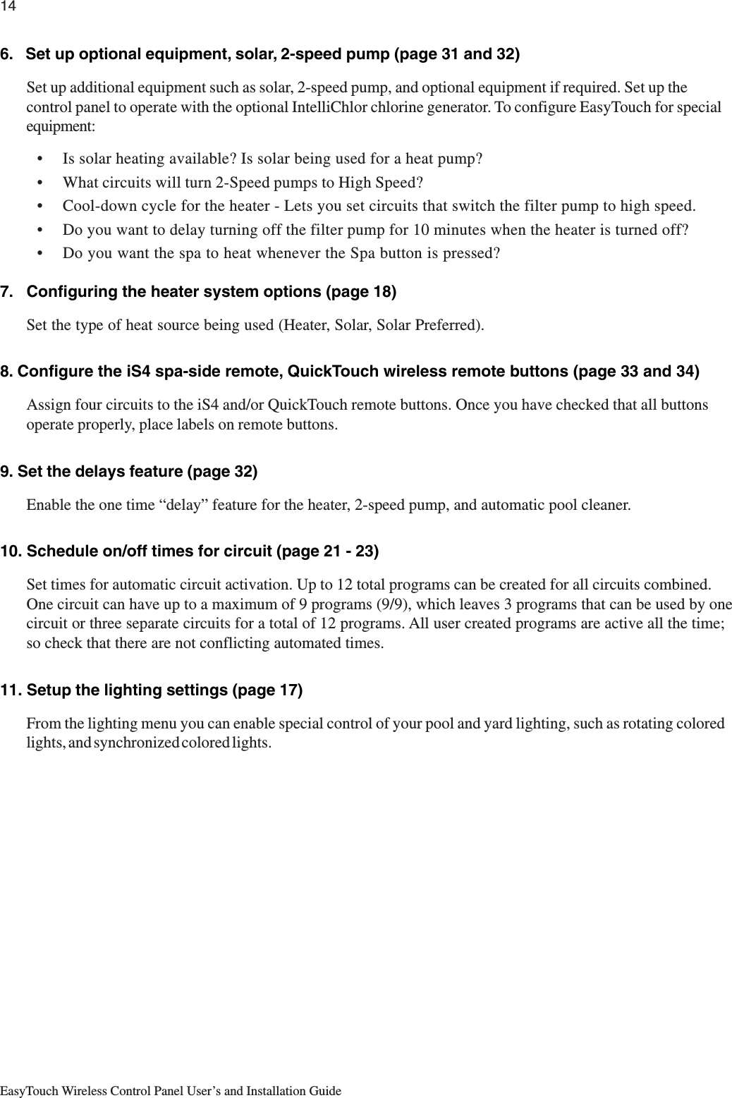
![26EasyTouch Wireless Control Panel User’s and Installation GuideSettings Menu: Circuit NamesLabeling Circuit Buttons on the Wireless Control PanelEasyTouch is shipped from the factory with each output circuit identified with its generic name (e.g. AUX 1,AUX 2, etc.). These generic circuit auxiliary names can be assigned a new names which are more descriptiveof the equipment being controlled. This makes it much easier to operate all of the equipment on your poolwithout having to memorize what each output controls.Circuit name labels are also provided to be placed on top of each auxiliary control panel button. Use thewritten list of circuit names (buttons) you made while setting up the EasyTouch load center. Identify what youlabeled circuit button 1, button 2 etc. The circuit names you assign should match the labels you put next to thecontrol panel buttons and the outdoor control panel buttons. Note that examples shown below use the factoryset generic output names. Note that examples shown use the factory set generic output names(AUX 1), for your system you should change these generic names.Circuit NamesTo assign circuit names:Up/Down buttons: Select the circuit number 1 of 9 (1/9). The generic circuitsnames: Spa, Pool AUX 1 - AUX 7 (9 circuit names), Spa, Pool, AUX 1 - AUX 7(EasyTouch 8) and AUX 1- AUX 3 (EasyTouch 4) each correspond to its assignedcircuit number.Right button: Move to EasyTouch preset circuit names and user defined customcircuit names.Up/Down buttons: Scroll through the list of alphabetical programmed names. If youcannot find a name to match your circuit, you can create your own custom name (seepage 30). Repeat for all the circuit buttons that you wish to assign names to. For acomplete list of EasyTouch circuit names, see page 27.Menu/Select: Press this button to save settings and to return to the Settings menuoptions. Press the button again to return to the main menu options or press again toreturn to the Main screen.Note: After a generic circuit name is changed and saved, the new name isdisplayed in the menu settings. You can view the default generic circuit names inthe menu settings before they were changed by enabling “Cir Names.” Refer to“Diagnostics: Cir Names (Off),” on page 40.Hi-Temp/Lo-Temp Controls for Single Body SystemFor an EasyTouch single body system, you have the option to control your pool and spa temperature settingsusing the Spa (Hi-Temp) and Pool (Lo-Temp) button on the Wireless control panel. Change the circuit nameSPA to HI-TEMP and POOL to LO-TEMP so that the display shows the correct temperature controls for yoursingle body system.▼ SETTINGS ▼ CIRCUIT NAMES CIR NAMESGetting There▲ Circuit NamesCircuit #: 1/9Circuit : Spa[SPA ] TS](https://usermanual.wiki/Pentair-Aquatic-Systems/EASYTOUCH/User-Guide-607198-Page-34.png)
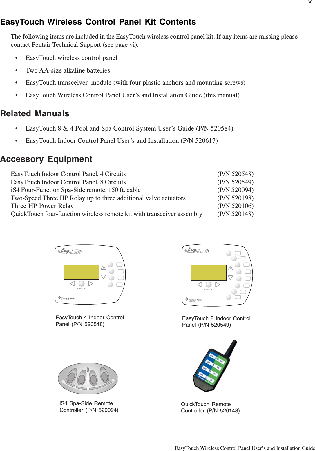
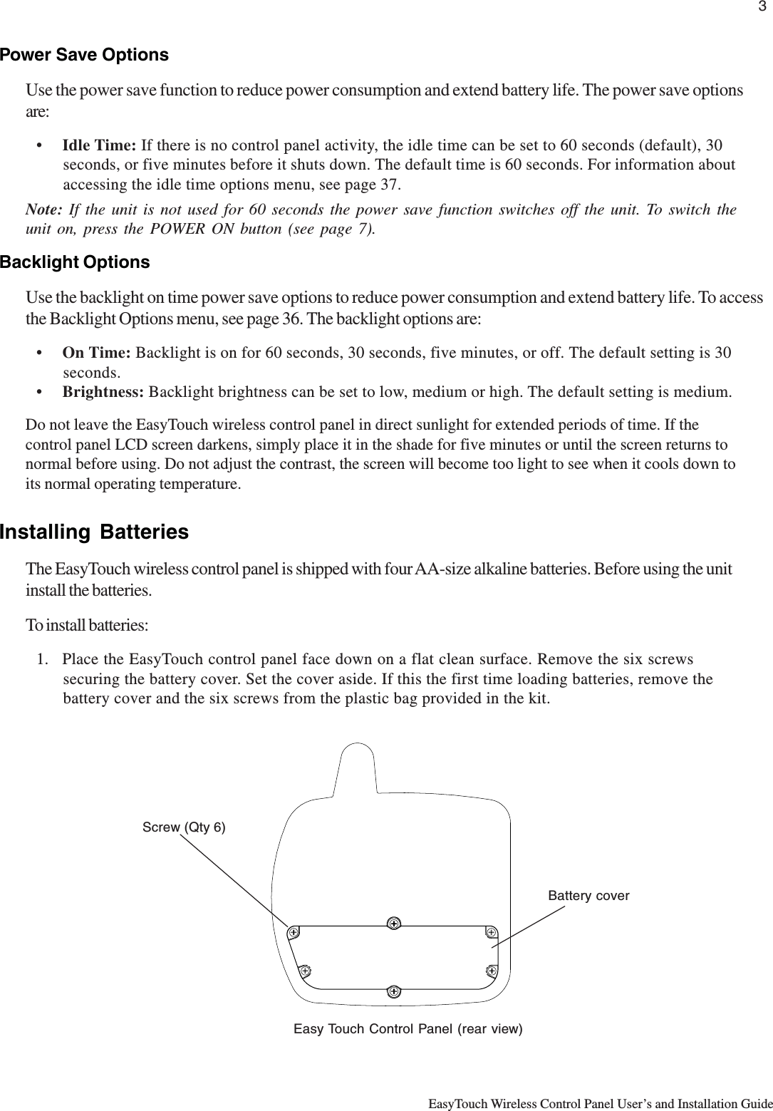
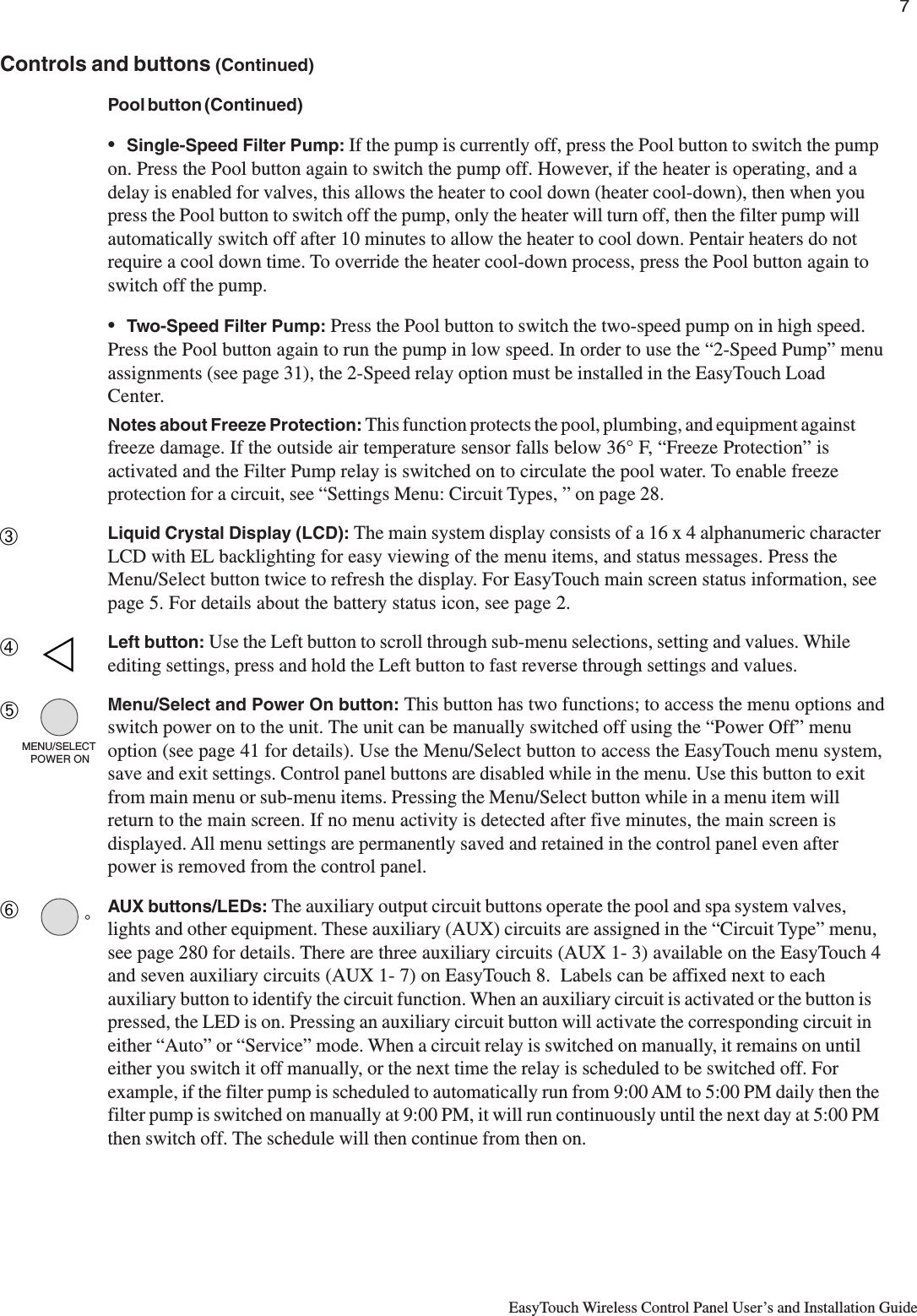
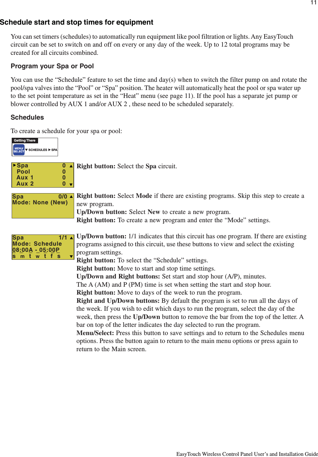
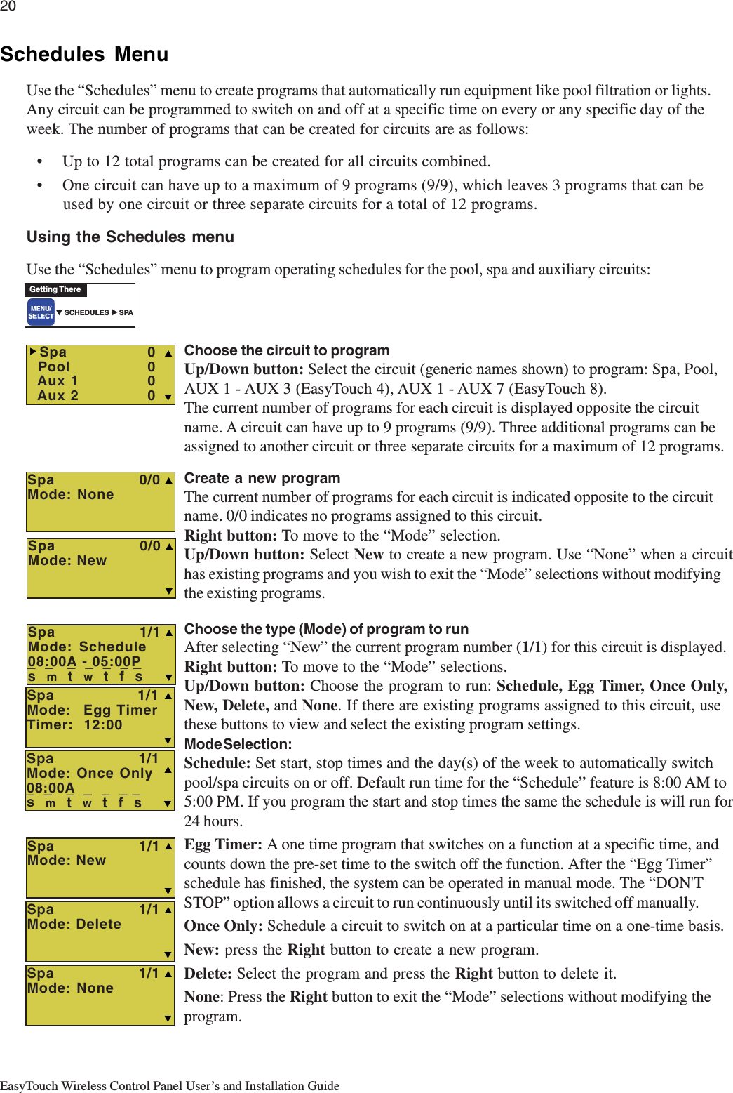
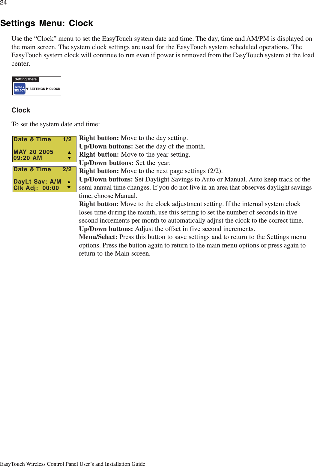
![28EasyTouch Wireless Control Panel User’s and Installation GuideSettings Menu: Circuit TypesAssigning Circuit TypesFrom the “Circuit Types” menu you can assign special logic to the circuits. For example, when setting up anautomatic pool cleaner pump, you would assign the circuit type MASTER CLEANER. With this "Cleaner"logic the cleaner pump would force the filter pump on, and the cleaner pump would start after a delay of fiveminutes. The cleaner pump would automatically shut off whenever the spa and/or solar is switched on.Freeze ProtectionFreeze protection switches on a circuit if the outside air temperature sensor detects the temperature is gettingclose to freezing (below 35° F). The system will switch on all circuits that have been assigned freezeprotection, and runs the circuits for 15 minutes to stop the pipes from freezing. This is especially important ifthere is a pool and spa combination. If freeze protection is set to both the spa and pool circuits, the filter pumpswitches on and the pool and spa valves alternate every 15 minutes to keep the water moving in both the pooland spa. This process continues until the freeze condition is over.Circuit TypesTo assign a circuit type and freeze protection:Up/Down buttons: Choose the circuit that you want to assign the function to. Thegeneric circuits names are: Spa, Pool, AUX 1 - AUX 7 (EasyTouch 8) andAUX 1- AUX 3 (EasyTouch 4).Right button: Move to circuit type setting to select the type of logic needed for yourcircuit.Up/Down buttons: Set the type of circuit to use. This is the circuit that you wish toassign the function logic to. For a complete list of preset circuit types, see “PresetCircuit Types,” on page 29.Right button: Move to Freeze Protection setting.Up/Down buttons: Select Ye s or No to assign freeze protection to this circuit. If“Yes” is selected, the circuit will switch on if the air temperature drops to 35° F.Note: for the POOL circuit the filter pump will have freeze protection. For theSPA circuit the filter pump will run and the pool/spa valves will switch betweenpool and spa at 15 minutes intervals throughout the freeze condition. For theMASTER CLEANER circuit freeze protection is generally not needed for poolcleaner pumps since they get water flow from the filter pump. Just make surethat POOL has freeze protection.Menu/Select: Press the Menu/Select button to save settings and to return to theSettings menu options. Press the button again to return to the main menu options orpress again to return to the Main screen.▼ SETTINGS ▼ CIRCUIT TYPES CIR TYPESGetting There▲ Select TypesCrct: Spa[MASTER SPA ]Freeze: No TS](https://usermanual.wiki/Pentair-Aquatic-Systems/EASYTOUCH/User-Guide-607198-Page-36.png)
![30EasyTouch Wireless Control Panel User’s and Installation GuideSettings Menu: Custom NamesThere are nearly 100 circuit names available to choose from. If you cannot find one to fit your application youcan create up to 10 custom names. Each name can be up to 11 alphanumeric characters. After a custom nameis saved, it is then available for selection in the Schedules, 2-Speed Pump, iS4 and QuickTouch menus.Custom NameTo assign a custom circuit name:Up/Down buttons: Select a custom circuit name number (1-10). You can create upto 10 custom circuit names.Right button: Move to custom circuit name setting.Up/Down/Right buttons: Enter the custom circuit name (11 characters maximum).Menu/Select: Press this button to save settings and to return to the Settings menuoptions. Press the button again to return to the main menu options or press again toreturn to the Main screen.Settings Menu: ValvesThis feature lets you assign a circuit to Valve A or B. The EasyTouch system can drive two auxiliary valveactuators (A and B) for applications such as solar heating and water features. By assigning AUX circuits tocontrol valve actuators, you can conserve auxiliary circuits for high voltage relays for controlling pumps andlights.Valve A: Resides on the motherboard. If solar heating is setup and is not configured as a heat pump, then thisValve A is dedicated for controlling the solar heating valve actuator.Valve B: Resides on the motherboard. Can be configured to be controlled by any circuit.ValvesTo assign a circuit to Valve A and Valve B:Up/Down buttons: Select a circuit to assign to Valve A. The circuits selections are:None, Spa, Pool, Aux 1-7, Heater (EasyTouch 8). None, Spa, Pool, Aux 1-3, Heater(EasyTouch 4).Right button: Move to Valve B setting.Up/Down buttons: Select a circuit to assign to Valve B. The circuits selections are:None, Spa, Pool, Aux 1-7, Heater (EasyTouch 8). None, Spa, Pool, Aux 1-3, Heater(EasyTouch 4).Menu/Select: Press this button to save settings and to return to the Settings menuoptions. Press the button again to return to the main menu options or press again toreturn to the Main screen.▼ SETTINGS ▼ CUSTOM NAMES CSTM NAMEGetting There▲ Cstm Name 1/10[USERNAME-01]TS▼ SETTINGS ▼ VALVES SETUP VALVESGetting There▲ TSSet ValvesA: [CLEANER ]B: [FOUNTAIN ]](https://usermanual.wiki/Pentair-Aquatic-Systems/EASYTOUCH/User-Guide-607198-Page-38.png)
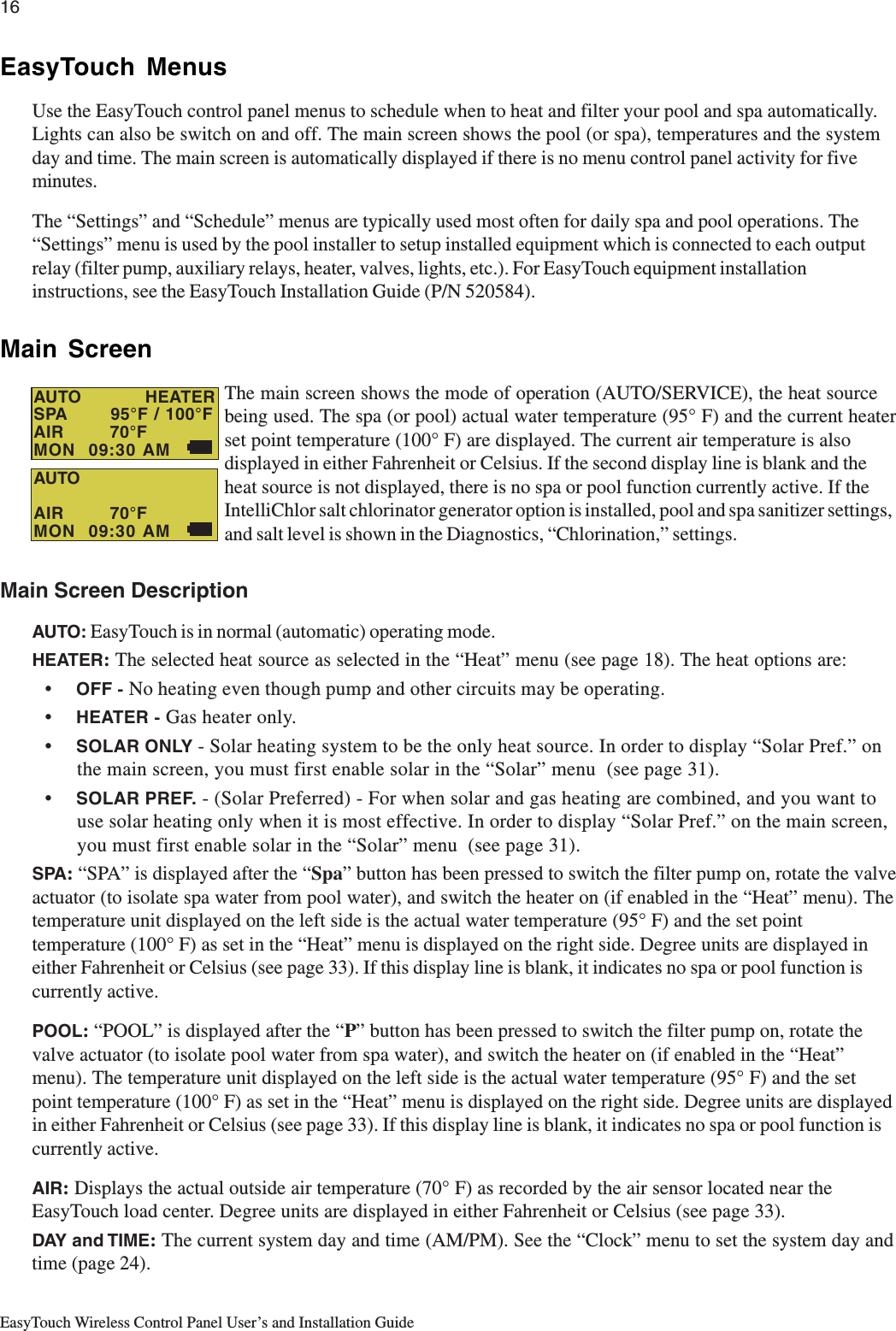
![31EasyTouch Wireless Control Panel User’s and Installation GuideSettings Menu: 2-Speed PumpEquipment circuits selected in this menu will automatically switch a two-speed filter pump to high speed whenthese circuits are on. If a two-speed pump is assigned to solar, a cleaner or a pump, when activated the pumpwill automatically run for five minutes in high speed then switch to low speed. For example, when on, the filterpump will switch to high speed whenever the JETS or CLEANER is on. There must be a two-speed relayinstalled in the EasyTouch Load Center in order for the “2-Speed Pump” menu settings to function.2-Speed PumpTo configure a two-speed pump to a circuit:Up/Down buttons: Select a circuit that will switch the filter pump to high speed. Youcan set up to four circuits to use a 2-speed pump (1/4, 2/4, 3/4, 4/4).Right button: Move to assign a circuit setting.Up/Down buttons: Select the circuit to assign to a two-speed pump. The circuitsselections are: None, Spa, Pool, Aux 1-7, Solar, Heater, Pool Heater, Spa Heater,Freeze (EasyTouch 8). None, Spa, Pool, Aux 1-3, Pool, Solar, Heater, Pool Heater,Spa Heater, Freeze (EasyTouch 4).Right button: Assign the next circuit (2/4).Up/Down buttons: Select the first digit for the circuit number (1/4, 2/4, 3/4, 4/4).Right button: Move to circuit setting.Up/Down buttons: Select the next circuit. When finished press Menu/Select.Menu/Select: Press this button to save settings and to return to the Settings menuoptions. Press the button again to return to the main menu options or press again toreturn to the Main screen.Settings Menu: SolarUse the solar settings to setup solar or configure solar as a heat pump:Setting Up Solar Control: Ensure that the solar temperature sensor is installed.About Installing Solar Heating: First, install the solar sensor at the collectors and connect to the EasyTouchload center. If “HEAT PUMP” is selected and is being used in place of a solar heating system, install Solarsensor near the EasyTouch Load Center. Connect the wires to the SOLAR screw terminals. Plug the solarvalve actuator cable into 3-pin socket marked VLV A on the motherboard. If solar booster pump is beinginstalled, connect pump to a power relay and plug low voltage cable from relay into 2-pin socket markedSOLAR.▼ SETTINGS ▼ Solar Solar Getting There▲ ▼ SETTINGS ▼ 2-Speed Pump 2-Speed PumpGetting There▲ TS2-Speed Pmp 1/4Circuit:[SPA HEATER ]](https://usermanual.wiki/Pentair-Aquatic-Systems/EASYTOUCH/User-Guide-607198-Page-39.png)
![33EasyTouch Wireless Control Panel User’s and Installation GuideSettings Menu: F° / C° (Fahrenheit/Celsius)The temperature settings for the water, solar and air can be displayed in either Fahrenheit or Celsius.F° / C°To change the temperature units:Up/Down buttons: Select either Fahrenheit or Celsius.Menu/Select: Press this button to save settings and to return to the Settings menuoptions. Press the button again to return to the main menu options or press again toreturn to the Main screen.Settings Menu: iS4 Spa-Side Remote ControllerYou can specify any iS4 Spa-Side remote button to control different functions by assigning each button to aspecific circuit. For example, you can use the iS4 Spa-Side remote to activate the spa circulation, and foroperating three auxiliary pieces of equipment (such as heat enabled, lights, jet pump, heat boost, air blower,waterfall, etc.).Assign iS4Before configuring the iS4 Spa-Side remote controller assign names to the circuits (see page 26).To assign iS4 Spa-Side buttons:Up/Down buttons: Select a circuit to one of the iS4 buttons. You can set up to fourcircuits (1/4, 2/4, 3/4, 4/4).Right button: Move to the circuit setting.Up/Down buttons: To configure the first button on the iS4 Spa-Side Remote, scrollthrough the circuit names and find the circuit that you would like to assign to the firstbutton on the iS4. The circuits selections are: None, Spa, Pool, Aux 1-7, Heat Boost,Heat Enable, (EasyTouch 8). None, Spa, Pool, Aux 1-3, Heat Boost, Heat Enable(EasyTouch 4). Note that “None” does not assign a circuit. Note: The “Heat Boost”feature will switch on the heater for seven minutes to increase the spa watertemperature. Each time the spa Heat Boost button is pressed, the temperature willincrease about 1° F. The temperature will not go beyond the 106° F limit.Right button: Assign the next circuit (2/4).Up/Down buttons: Select the first digit for the circuit number (1/4, 2/4, 3/4, 4/4) andrepeat the procedure for the other three buttons.Menu/Select: Press this button to save settings and to return to the Settings menuoptions. Press the button again to return to the main menu options or press again toreturn to the Main screen.Note: To disable or enable the iS4 Spa-Side remote, see Settings Menu: Spa Side,” on page 37.▼ SETTINGS ▼ IS4 ASSIGN iS4Getting There▲ T F° / C° FAHRENHEITS▼ SETTINGS ▼ F˚ / C˚ F˚ / C˚Getting There▲ T Assign iS4 1/4 Circuit: [HEAT BOOST ]S](https://usermanual.wiki/Pentair-Aquatic-Systems/EASYTOUCH/User-Guide-607198-Page-41.png)
![34EasyTouch Wireless Control Panel User’s and Installation GuideSettings Menu: QuickTouch (QT4) Wireless RemoteThe QuickTouch QT4 wireless remote controller provides switching of up to four circuits. For example, youcan use the QT4 wireless remote to activate the spa circulation, and for operating three auxiliary pieces ofequipment (such as heat enabled, lights, jet pump, heat boost, air blower, waterfall, etc.).Each of the four functions on the QT4 wireless controller has an on and an off button. To switch a circuit onor off, press and hold the appropriate button for at least a full second.The QT4 buttons can be assigned to any available circuit. However, the QT4 has the following preset circuitsassigned to the four buttons:• Spa button activates the spa circuit.• A button activates Auxiliary 1 circuit.• B button activates Auxiliary 2 circuit.• C button activates Auxiliary 3 circuit.Assign QT4To assign circuits to the QuickTouch wireless controller buttons:Up/Down buttons: Select a circuit to assign to one of the QuickTouch wirelessremote buttons. You can set up to four circuits (1/4, 2/4, 3/4, 4/4).Right button: Move to the circuit setting.Up/Down buttons: To configure the first button on the QuickTouch wireless remote,scroll through the circuit names and find the circuit that you would like to assign to thefirst button on the QT4. The circuits selections are: None, Spa, Pool, Aux 1-7, HeatBoost, Heat Enable, (EasyTouch 8). None, Spa, Pool, Aux 1-3, Heat Boost, HeatEnable (EasyTouch 4). Note: The “Heat Boost” feature will switch on the heater forseven minutes to increase the spa water temperature. Each time the spa Heat Boostbutton is pressed, the temperature will increase about 1° F. The temperature will notgo beyond the 106° F limit.Right button: Assign the next circuit (2/4).Up/Down buttons: Select the first digit for the circuit number (1/4, 2/4, 3/4, 4/4),then repeat the procedure for the other three buttons.Menu/Select: Press this button to save settings and to return to the Settings menuoptions. Press the button again to return to the main menu options or press again toreturn to the Main screen.▼ SETTINGS ▼ QUICKTOUCH ASSIGN QT4Getting There▲ T Assign QT4 1/4 Circ: [Spa]S](https://usermanual.wiki/Pentair-Aquatic-Systems/EASYTOUCH/User-Guide-607198-Page-42.png)
![35EasyTouch Wireless Control Panel User’s and Installation GuideSettings Menu: Man Heat (Off/On)By default manual heat (Man Heat) is set to “On,” which allows your spa to begin to heat whenever it ismanually switched on, (by pressing the Valves (V) button and Filter Pump button on the main outdoor controlpanel or the Spa button on the wireless control panel), even if the Heat menu setting is set to “OFF” (see page18). Your spa will also begin to heat when switched on by the iS4 Spa-Side remote. This feature allows you toprogram your spa to filter daily with the heater set to off, and then be ready to heat whenever the Spa button ispressed manually.Man HeatTo enable or disable spa manual heat when switched on manually:Right button: Select Off to disable or On to automatically begin spa heatingwhenever the spa is switched on manually.Menu/Select: Press this button to save settings and to return to the Main screen.Settings Menu: CalibrationThe EasyTouch system includes two temperature sensors (10 kΩ) for water and ambient air temperature. Youcan also add an additional sensor for controlling solar heating systems. Generally, these sensors are accurateand you do not have to calibrate them. However, long plumbing runs and water features can causetemperatures at a body of water to be different from the temperature sensor reading. You can manuallyrecalibrate the sensors to adjust for this. You only need to calibrate one body of water, since the temperaturesensor is common to both the pool and spa. The system must be in “Service” mode to calibrate sensors.CalibrationBefore you start, you need an accurate all weather thermometer. If you are calibrating the air sensor, wait untilthe sensor is not in direct sunlight. For the air temperature sensor, make sure that the sensor is located in theshade for accurate readings.To calibrate the water, air and solar temperature sensors:1. Press the Mode button on the control panel to place the system in “Service” manual mode.2. Press the Filter Pump (F) button to switch on the pool/spa filter pump.3. Place the thermometer in the spa or pool water. Take an accurate temperature reading. Whencalibrating the air sensor, place the thermometer next to the air sensor. The air sensor is normallylocated near or under the EasyTouch load center enclosure, not inside theenclosure. Take an accurate temperature reading in the shade.4. Use the Up or Down buttons to raise or lower the water temperature tomatch the corresponding thermometer temperature reading.5. After calibrating the water sensor, use the Right button to move to the“AIR” setting and repeat step 4 and repeat the procedure for the solarsensor. Ensure that the solar sensor is in the sun for accurate readings.6. After calibrating all the sensors, press the Menu/Select button to save settings and to return to theSettings menu options. Press the button again to return to the main menu options or press again toreturn to the Main screen.▼ SETTINGS ▼ CALIBRATION CALIBRATIONGetting There▲ TCalibrationWater: 70°FAir: 80°FSolar: 90°FSTTemp UnitsiS4Quick TouchMan Heat [Off]S▼ SETTINGS ▼ MAN HEAT [On/Off]Getting There](https://usermanual.wiki/Pentair-Aquatic-Systems/EASYTOUCH/User-Guide-607198-Page-43.png)
![37EasyTouch Wireless Control Panel User’s and Installation GuideSettings Menu: Power Save OptionsThis option sets the time that the EasyTouch wireless control panel will shut down if there is no control panelactivity. Use the power save options to reduce power consumption and extend battery life. The options are:•Pwrsave Options: Set the power save time to 30 seconds, 60 seconds, or five minutes before theunit shuts down. The default time is 60 seconds.Note: If the unit is not used for 60 (default) seconds the power save function switches off the unit. Toswitch the unit on, press the “POWER” button. The unit can also be switched off manually using the“Power Off” function, see page 41 for more information.Idle TimeTo set the idle time for the EasyTouch wireless control panel:Right or Up/Down buttons: Select 30 S, 60 S or 5 M.Menu/Select: Press this button to save settings and to return to the previous screen.Spa Side [Off/On]Enable or disable the iS4 Spa Side remote. This feature is useful for families with young children or when yougo on vacation. It allows you to switch off the iS4 Spa Side remote at the control panel so that the remotecannot be used.Spa SideTo enable or disable the iS4 Spa Side remote:Right button:: Select On or Off to enable or disable the spa side remote.Menu/Select: Press this button to save settings and to return to the Main screen.▼ SPA SIDE [On/Off]Getting ThereTDelay CancelSchedulesSettingsSpa Side [On ]S▼ SETTINGS ▼ POWER SAVE OPTIONSGetting TherePWRSAVE OPTIONSIDLE TIME: 60 S](https://usermanual.wiki/Pentair-Aquatic-Systems/EASYTOUCH/User-Guide-607198-Page-45.png)
![39EasyTouch Wireless Control Panel User’s and Installation GuideDiagnostics Menu: ChlorinatorDisplays the current IntelliChlor chlorination system status. For more information, refer to the IntelliChlorElectronic Chlorine Generator User’s Guide (P/N 520589).Menu/Select: Press this button to return to the Settings menu options. Press thebutton again to return to the main menu options or press again to return to the Mainscreen.SALT LEVEL: Displays the current salt level. Values from 0 to 12750 ppm in 50 ppmincrements.IntelliChlor Status messages:SUPER CHLORINATE: IntelliChlor is in “Super Chlorination mode (see page 25)COM LINK ERROR: Check cable from IntelliChlor to EasyTouch motherboard.Check FLOW/PCB: Check IntelliChlor electrolytic cell controller. Refer to IntelliChlorUser’s Guide troubleshooting information.LOW SALT: Add salt to pool water. The water salt level is between 2500 ppm and2900 ppm. The IntelliChlor will continue to produce chlorine at a reduced level.VERY LOW SALT: Not enough salt in pool. The water salt level has fallen below 2500parts per million (ppm). IntelliChlor will not produce chlorine until additional salt isadded manually.HIGH CURRENT: Check IntelliChlor electrolytic cell controller. Refer to IntelliChlorUser’s Guide troubleshooting information..CLEAN CELL!!: Cell has calcium build up and requires cleaning. Refer to IntelliChlorUser’s Guide for cleaning instructions.LOW VOLTAGE: Check IntelliChlor electrolytic cell controller. Refer to IntelliChlorUser’s Guide troubleshooting information.OK - NO ERRORS: IntelliChlor is in normal operating mode.Diagnostics Menu: Water TempDisplays the current water temperature for the pool and spa.Menu/Select: Press this button to return to the Settings menu options. Press thebutton again to return to the main menu options or press again to return to the Mainscreen.Diagnostics Menu: Solar TempDisplays the current temperature.Menu/Select: Press this button to return to the Settings menu options. Press thebutton again to return to the main menu options or press again to return to the Mainscreen.▼ DIAGNOSTICS ▼ WATER TEMPGetting There▼ DIAGNOSTICS ▼ SOLAR TEMPGetting There▼ DIAGNOSTICS ▼ CHLORINATORGetting ThereTChlorinatorSalt Level:3200ppmStatus:[OK-NO ERRORS]STWater Temperature75° FSTSSolar Temperature85° F](https://usermanual.wiki/Pentair-Aquatic-Systems/EASYTOUCH/User-Guide-607198-Page-47.png)
![40EasyTouch Wireless Control Panel User’s and Installation GuideDiagnostics Menu: Air TempDisplays the current outside air temperature.Menu/Select: Press this button to return to the Settings menu options. Press thebutton again to return to the main menu options or press again to return to the Mainscreen.Diagnostics Menu: Disp CodesPerform a communications test with installed equipment. Use this feature when testing the system.To start test:Down button: Select Ye s to enable the feature.Menu/Select or Right button: Press either of these buttons to startcommunications test. Digits display on the right side of all menu screens indicatingverification transmit and received packets.To stop test: Go to the “Disp Op Codes” menu and select No, then press theMenu/Select button to exit.Diagnostics Menu: Cir Names: [Off/On]This feature is useful if you have renamed many circuits and want to view the original factory default circuitnames.To enable:Right button: Select On to view the factory default circuit names.Menu/Select: Press this button to exit.To disable:Right button: Select Off to disable the feature.Menu/Select: Press this button to exit.Diagnostics Menu: Reset SystemReset the EasyTouch wireless control panel. Resetting the wireless control panel will not effect the storedsystem configuration settings.Right button: Press the Right button to reset system. The main screen will bedisplayed and communication will be established with the EasyTouch outdoor controlpanel at the pool equipment pad.▼ DIAGNOSTICS ▼ AIR TEMPGetting ThereT Air Temperature72° FST Disp Op Codes Display? NoST Solar Temp Air Temp Disp codes Cir Names [Off]SX▼ DIAGNOSTICS ▼ CIR NAMESGetting There[Off]▼ DIAGNOSTICS ▼ DISP CODESGetting ThereTSX Air Temp Disp codes Cir Names [Off] Reset System▼ DIAGNOSTICS ▼ RESET SYSTEMGetting There](https://usermanual.wiki/Pentair-Aquatic-Systems/EASYTOUCH/User-Guide-607198-Page-48.png)
![41EasyTouch Wireless Control Panel User’s and Installation GuideDiagnostics Menu: Flash UpdateUse this feature to update the EasyTouch wireless control panel firmware. The unit must be connected to aPC in order to update the firmware. Press MENU/SELECT to exit the flash mode.Power OFFThe “Power Off” function switches off battery power to the EasyTouch wireless control panel. Use thisfunction to manually switch off the unit. To switch the unit on, press the Power ON button. Right button: Press the Right button to switch off the unit.▼ DIAGNOSTICS ▼ FLASH UPDATEGetting There▼ POWER OFF [PRESS TO SWITCH OFF]Getting There▼](https://usermanual.wiki/Pentair-Aquatic-Systems/EASYTOUCH/User-Guide-607198-Page-49.png)