Pentair Aquatic Systems EASYTOUCH Easy Touch Wireless User Manual EasYTouch Wireless Control Panel Preliminary
Pentair Aquatic Systems Easy Touch Wireless EasYTouch Wireless Control Panel Preliminary
User Manual
EasyTouch
Wireless Control Panel
User’s and Installation Guide
AUTO HEATER
SPA 95°F / 100°F
AIR 70°F
MON 09:30 AM
POWER ON
PRELIMINARY ISSUE
© 2005 Pentair Water Pool and Spa, Inc. All rights reserved
This document is subject to change without notice
1620 Hawkins Ave., Sanford, NC 27330 • (919) 566-8000
10951 West Los Angeles Ave., Moorpark, CA 93021 • (805) 523-2400
Trademarks and disclaimers
EasyTouch, IntelliChlor, IntelliFlo, QuickTouch and the Pentair Water Pool and Spa logo are trademarks of Pentair
Water Pool and Spa, Inc. Other trademarks and trade names may be used in this document to refer to either the
entities claiming the marks and names or their products. Pentair Water Pool and Spa, Inc. disclaims proprietary
interest in marks and names of others.
P/N 520688 - Rev X1 - September 26 2005

i
EasyTouch Wireless Control Panel User’s and Installation Guide
Contents
Section 1: EasyTouch Wireless Control Panel Overview ........................................................... 1
Introduction ...................................................................................................................................... 1
Battery Overview ............................................................................................................................... 2
Safety Precautions when using batteries .......................................................................................... 2
Checking the battery charge ............................................................................................................. 2
Power save options .......................................................................................................................... 3
Backlight Options ............................................................................................................................. 3
Installing batteries ............................................................................................................................ 3
EasyTouch Wireless Control Panel Overview .................................................................................... 5
EasyTouch Wireless Control Panel Buttons ..................................................................................... 6
EasyTouch Wireless Control Panel Display ...................................................................................... 8
Switching Power on .......................................................................................................................... 9
Quick Start Spa and Pool Operations .......................................................................................... 9
Heat your spa or pool ................................................................................................................... 9
Adjust your spa or pool heat settings ...........................................................................................9
Switch on lights manually ............................................................................................................. 10
Using the Once Only timer feature ................................................................................................ 10
Schedule start and stop times for equipment ................................................................................ 11
Program your Spa or Pool............................................................................................................. 11
Schedules .................................................................................................................................... 11
Setting the Egg Timer Feature ...................................................................................................... 12
Section 2: Setting up EasyTouch .................................................................................................. 13
Setting up the System for the First Time .......................................................................................... 13
EasyTouch Menu Structure .............................................................................................................. 15
EasyTouch Menus .......................................................................................................................... 16
Main Screen ................................................................................................................................. 16
Lights Menu ................................................................................................................................. 17
Heat Menu .................................................................................................................................... 18
Pool Temp/Src ........................................................................................................................... 18
Spa Temp/Src ............................................................................................................................ 18
Delay Cancel Menu ...................................................................................................................... 19
Schedules Menu .......................................................................................................................... 20
Using the Schedules menu ........................................................................................................20
Program your Spa or Pool .......................................................................................................... 21
Schedules.................................................................................................................................. 21
Using the Once Only feature ...................................................................................................... 21
Using the Egg Timer (count-down) Feature ................................................................................ 23
Settings Menu: Clock ................................................................................................................... 24
Settings Menu: IntelliChlor ............................................................................................................ 25
Settings Menu: Circuit Names ...................................................................................................... 26
Labeling Circuit Buttons on the Indoor Control Panel .................................................................. 26
Hi-Temp/Lo-Temp Controls for Single Body System ................................................................... 26
EasyTouch Circuit Names .......................................................................................................... 27
Settings Menu: Circuit Types ........................................................................................................ 28
Assigning Circuit Types ................................................................................................................ 28
Freeze Protection ...................................................................................................................... 28
Circuit Types .............................................................................................................................. 28
Preset Circuit Types................................................................................................................... 29

ii
EasyTouch Wireless Control Panel User’s and Installation Guide
Section 2: EasyTouch Menus (Continued)
Settings Menu: Custom Names .................................................................................................... 30
Settings Menu: Valves .................................................................................................................. 30
Settings Menu: 2-Speed Pump .....................................................................................................31
Settings Menu: Solar .................................................................................................................... 31
Settings Menu: Delays ................................................................................................................. 32
Settings Menu: F° / C° (Celsius/Fahrenheit) ................................................................................. 33
Settings Menu: iS4 Spa-Side Remote Controller ........................................................................... 33
Settings Menu: QuickTouch (QT4) Wireless Remote .................................................................... 34
Settings Menu: Man Heat (Off/On) ................................................................................................35
Settings Menu: Calibration ........................................................................................................... 35
Settings Menu: Erase EEPROM (Erase System Memory) ........................................................... 36
Settings Menu: Backlight Options ................................................................................................36
Settings Menu: Power Save Options ............................................................................................ 37
Spa Side [On/Off] ......................................................................................................................... 37
Diagnostics Menu: Software Rev .................................................................................................. 38
Diagnostics Menu: Bootloader Rev ............................................................................................... 38
Diagnostics Menu: Self Test ......................................................................................................... 38
Diagnostics Menu: Chlorinator ...................................................................................................... 39
Diagnostics Menu: Water Temp ....................................................................................................39
Diagnostics Menu: Solar Temp ..................................................................................................... 39
Diagnostics Menu: Air Temp ......................................................................................................... 40
Diagnostics Menu: Disp Codes ....................................................................................................40
Diagnostics Menu: Cir Names: [Off/On] ........................................................................................ 40
Diagnostics Menu: Reset System ................................................................................................ 40
Diagnostics Menu: Flash Update ..................................................................................................41
Power OFF ................................................................................................................................... 41
Section 3: Troubleshooting ........................................................................................................... 43
Troubleshooting ................................................................................................................................43
Frequently Asked Questions (FAQ) .................................................................................................. 43
How do I setup a two-speed pump? .................................................................................................. 43
Can I switch the heater on and change the temperature from the spa? ............................................. 43
How do I switch on solar heating? .................................................................................................... 43
EasyTouch Error Messages ............................................................................................................. 44
Self Test Error Codes ....................................................................................................................... 44
Maximum Programs Exceeded ........................................................................................................ 45
IntelliChlor Error Messages .............................................................................................................. 45
System Problem Diagnosis .............................................................................................................. 46
Problem: iS4 fails to operate. ........................................................................................................... 46
Problem: The Quick Touch remote will not work, or will not work dependably ................................... 47
Section 4: EasyTouch Transceiver Module Installation .............................................................. 45
Installing the EasyTouch Transceiver Module .................................................................................... 49
EasyTouch wireless control panel kit ................................................................................................ 49
Mounting the EasyTouch Transceiver Module ................................................................................... 49
Connecting the EasyTouch Transceiver to the Load Center ............................................................... 51
Glossary of Terms .......................................................................................................................... 53
Contents
iii
EasyTouch Wireless Control Panel User’s and Installation Guide
IMPORTANT SAFETY PRECAUTIONS
Important Notice:
Attention Installer: This manual contains important information about the installation, operation and safe use of
this product. This information should be given to the owner and/or operator of this equipment.
WARNING - Before installing this product, read and follow all warning notices and instructions which are
included. Failure to follow safety warnings and instructions can result in severe injury, death, or property
damage. Call (800) 831-7133 for additional free copies of these instructions.
WARNING - Water temperature in excess of 100 degrees Fahrenheit may be hazardous to your health.
Prolonged immersion in hot water may induce hyperthermia. Hyperthermia occurs when the internal temperature
of the body reaches a level several degrees above normal body temperature of 98.6° F (37° C). The symptoms
of hyperthermia include drowsiness, lethargy, dizziness, fainting, and an increase in the internal temperature of
the body.
The effects of hyperthermia include: 1) Unawareness of impending danger. 2) Failure to perceive heat. 3) Failure
to recognize the need to leave the spa. 4) Physical inability to exit the spa. 5) Fetal damage in pregnant women.
6) Unconsciousness resulting in danger of drowning.
WARNING - To reduce the risk of injury, do not permit children to use this product unless they are closely
supervised at all times.
WARNING - The use of alcohol, drugs, or medication can greatly increase the risk of fatal
hyperthermia in hot tubs and spas.
WARNING - Control System is intended to control heaters with built-in high limit circuits ONLY. Failure to do
so may cause property damage or personal injury.
WARNING - Do not use this product to control an automatic pool cover. Swimmers may become entrapped
underneath the cover.
WARNING - For units intended for use in other than single-family dwellings, a clearly labeled emergency
switch shall be provided as part of the installation. The switch shall be readily accessible to the occupants and
shall be installed at least 10 feet (3.05 m) away, adjacent to, and within sight of, the unit.
CAUTION - Except for listed spa-side remote controls, install a minimum of five (5) feet from the inside wall
of the pool and spa.

iv
EasyTouch Wireless Control Panel User’s and Installation Guide
IMPORTANT SAFETY PRECAUTIONS (Continued)
General Installation Information
1. All work must be performed by a licensed electrician, and must conform to all national, state, and local
codes.
2. Install to provide drainage of compartment for electrical components.
3. If this system is used to control underwater lighting fixtures, a ground-fault circuit interrupter (GFCI)
must be provided for these fixtures. Conductors on the load side of the ground-fault circuit-interrupter
shall not occupy conduit, junction boxes or enclosures containing other conductors unless such
conductors are also protected by a ground-fault circuit-interrupter. Refer to local codes for details.
4. A terminal bar stamped is located inside the supply terminal box. To reduce the risk of electric
shock, this terminal must be connected to the grounding means provided in the electric supply service
panel with a continuous copper wire equivalent in size to the circuit conductors supplying this
equipment (no smaller than 12 AWG or 3.3 mm). The bonding lug(s) provided on this unit are intended
to connect a minimum of one No. 8 AWG for US installation and two No. 6 AWG for Canadian
installations solid copper conductor between this unit and any metal equipment, metal enclosures or
electrical equipment, metal water pipe, or conduit within 5 feet (1.5 m) of the unit.
5. The electrical supply for this product must include a suitably rated switch or circuit breaker to open all
ungrounded supply conductors to comply with Section 422-20 of the National Electrical Code, ANSI/
NFPA 70.1987. The disconnecting means must be readily accessible to the tub occupant but installed
at least 10 ft. (3.05 m) from the inside wall of the pool.
6. Supply conductor must be sized to support all loads. Maximum supply conductor current must
be 125 Amps at 125 VAC.
Canada - Industry Canada (IC) - This device complies with RSS210 of Industry Canada. (1999).
Operation is subject to the following two conditions: (1) this device may not cause interference, and
(2) this device must accept any interference, including interference that may cause undesired
operation of the device.
FCC Standard - 47 CFR Part 15, Subpart C (Section 15.247). This version is limited to chapter 1
to chapter 11 by specified firmware controlled in the U.S.A.
Instruction to user - This equipment has been tested and found to comply with the limits for a
Class B digital device, pursuant to Part 15 of the FCC Rules. These limits are designed to provide
reasonable protection against harmful interference in a residential installation. This equipment
generates, uses and can radiate radio frequency energy and, if not installed and used in accordance
with the instructions, may cause harmful interference to radio communications. However, there is no
guarantee that interference will not occur in a particular installation. If this equipment does cause
harmful interference to radio or television reception, which can be determined by turning the
equipment off and on, the user is encouraged to try to correct the interference by one or more of the
following measures:
• Reorient or relocate the receiving antenna.
• Increase the separation between the equipment and receiver.
• Connect the equipment into an outlet on a circuit different from that to which the receiver is
connected.
• Consult the dealer or an experienced radio/TV technician for help.
Note: The user is cautioned that changes and modifications made to the equipment without the
approval of the manufacturer could void the user’s authority to operate this equipment.
v
EasyTouch Wireless Control Panel User’s and Installation Guide
EasyTouch Wireless Control Panel Kit Contents
The following items are included in the EasyTouch wireless control panel kit. If any items are missing please
contact Pentair Technical Support (see page vi).
• EasyTouch wireless control panel
• Two AA-size alkaline batteries
• EasyTouch transceiver module (with four plastic anchors and mounting screws)
• EasyTouch Wireless Control Panel User’s and Installation Guide (this manual)
Related Manuals
• EasyTouch 8 & 4 Pool and Spa Control System User’s Guide (P/N 520584)
• EasyTouch Indoor Control Panel User’s and Installation (P/N 520617)
Accessory Equipment
EasyTouch Indoor Control Panel, 4 Circuits (P/N 520548)
EasyTouch Indoor Control Panel, 8 Circuits (P/N 520549)
iS4 Four-Function Spa-Side remote, 150 ft. cable (P/N 520094)
Two-Speed Three HP Relay up to three additional valve actuators (P/N 520198)
Three HP Power Relay (P/N 520106)
QuickTouch four-function wireless remote kit with transceiver assembly (P/N 520148)
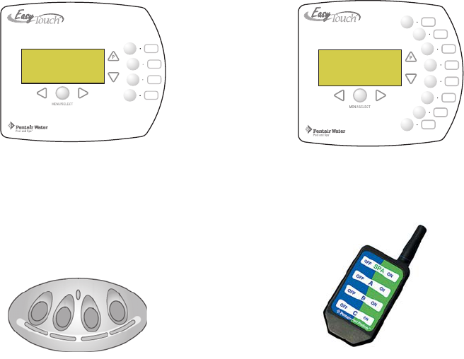
iS4 Spa-Side Remote
Controller (P/N 520094)
QuickTouch Remote
Controller (P/N 520148)
EasyTouch 4 Indoor Control
Panel (P/N 520548)
EasyTouch 8 Indoor Control
Panel (P/N 520549)
vi
EasyTouch Wireless Control Panel User’s and Installation Guide
Technical Support
Contact Technical Support at:
Sanford, North Carolina (8 A.M. to 5 P.M.)
Phone: (800) 831-7133
Fax: (919) 566-8920
Moorpark, California (8 A.M. to 5 P.M.)
Phone: (800) 831-7133 (Ext. 6502)
Fax: (805) 530-0194
Web sites: visit www.pentairpool.com and www.stritepool.com
1
EasyTouch Wireless Control Panel User’s and Installation Guide
Section 1
EasyTouch Wireless Control Panel Overview
Introduction
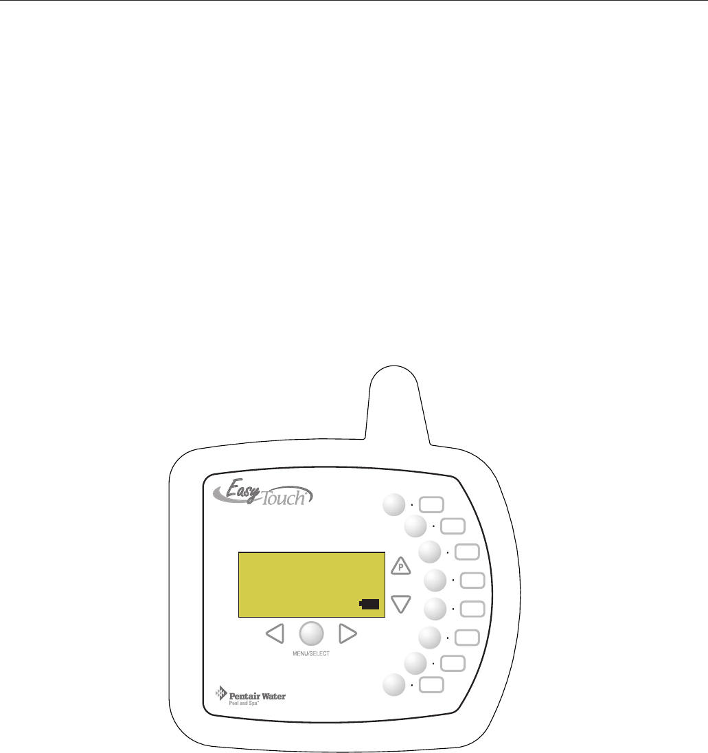
The EasyTouch wireless control panel gives you the freedom to operate your pool and spa daily operations
from around your pool and spa area. The unit can operate up to 300 feet from the EasyTouch transceiver
module which is located near the EasyTouch load center. There is enough battery power to operate the whole
summer season without changing batteries, Using the power saving menu options you can also reduce power
consumption and extend battery life. The EasyTouch wireless control panel is water resistent, however, is not
intended to be submersible.
The EasyTouch wireless control panel is designed to be used with the EasyTouch 8 or EasyTouch 4 system.
The EasyTouch system can automatically control your pool and spa equipment, lights and other optional
equipment . You can also manually control all EasyTouch system operations from the EasyTouch outdoor
control panel located at the pool equipment pad. Using the outdoor control panel buttons you can manually
override any automatic settings. For more information, refer to the EasyTouch User’s Guide (P/N 520584).
AUTO HEATER
SPA 95°F / 100°F
AIR 70°F
MON 09:30 AM
EasyTouch Wireless Control Panel
POWER ON

2
EasyTouch Wireless Control Panel User’s and Installation Guide
Battery Overview
The average battery life for the EasyTouch wireless control panel can last the summer season with normal
use. Battery life varies depending on the type of batteries used. The following battery types are compatible
with the EasyTouch wireless control panel:
•AA-size alkaline battery (quantity 4 provided in the kit)
•AA-size Ni-MH rechargeable battery (quantity 4, sold separately)
Safety Precautions when using batteries
Read the following important information before installing batteries into the EasyTouch wireless control panel.
• Never use batteries with split or peeling outer casings
• Never use combinations of different types of batteries or new and used batteries together
• Do not use manganese or Ni-Cd batteries
• Ensure that batteries poles are clean. Dirty poles can shorten battery life
• The time for which AA-size alkaline batteries can be used vary depending on the brand. Some brands
may provide less power than others. Note that the time Alkaline batteries can be used decreases in
cold conditions (0° C to 10° C (32° F to 50° F)). Therefore, it is recommended to use AA-size
Ni-MH batteries in the unit.
• When first purchased, or if left unused for a long period, the amount of time that the AA-size alkaline,
Ni-MH, or rechargeable batteries can be used, may be shortened.
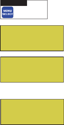
Checking the battery charge
A check battery status icon displays on the main screen of the EasyTouch wireless control panel. The check
battery icon is located in the lower right corner of the main screen.
Check battery icons
Ample battery charge.
Sufficient charge left in the batteries to operate the unit. The unit’s estimated battery life varies
greatly depending on use and backlight display time (see page 3).
Batteries are depleted. Before the batteries are completely depleted this icon will start flashing,
indicating that the LCD will shortly go blank and the EasyTouch wireless will stop working.
Replace or recharge the batteries. Depending on the type of batteries installed, this icon may
display more quickly.
AUTO HEATER
SPA 95°F / 100°F
AIR 70°F
MON 09:30 AM
3
EasyTouch Wireless Control Panel User’s and Installation Guide
Power Save Options
Use the power save function to reduce power consumption and extend battery life. The power save options
are:
•Idle Time: If there is no control panel activity, the idle time can be set to 60 seconds (default), 30
seconds, or five minutes before it shuts down. The default time is 60 seconds. For information about
accessing the idle time options menu, see page 37.
Note: If the unit is not used for 60 seconds the power save function switches off the unit. To switch the
unit on, press the POWER ON button (see page 7).
Backlight Options
Use the backlight on time power save options to reduce power consumption and extend battery life. To access
the Backlight Options menu, see page 36. The backlight options are:
•On Time: Backlight is on for 60 seconds, 30 seconds, five minutes, or off. The default setting is 30
seconds.
•Brightness: Backlight brightness can be set to low, medium or high. The default setting is medium.
Do not leave the EasyTouch wireless control panel in direct sunlight for extended periods of time. If the
control panel LCD screen darkens, simply place it in the shade for five minutes or until the screen returns to
normal before using. Do not adjust the contrast, the screen will become too light to see when it cools down to
its normal operating temperature.
Installing Batteries
The EasyTouch wireless control panel is shipped with four AA-size alkaline batteries. Before using the unit
install the batteries.
To install batteries:
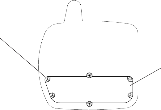
1. Place the EasyTouch control panel face down on a flat clean surface. Remove the six screws
securing the battery cover. Set the cover aside. If this the first time loading batteries, remove the
battery cover and the six screws from the plastic bag provided in the kit.
Screw (Qty 6)
Easy Touch Control Panel (rear view)
Battery cover
4
EasyTouch Wireless Control Panel User’s and Installation Guide
Installing batteries (Continued)
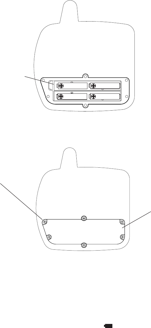
2. Load the four batteries into the battery compartment. Orient the positive polarity end of each battery
as shown below.
3. Install the battery cover and secure with the six screws. Make sure that the battery cover is secure
and that all the screws are tightened.
4. Power up the unit: To switch the unit on, press the Power On button located on the front of the
unit.
5. Display messages after replacing batteries: After replacing depleted batteries a check battery
message is displayed on the screen. Press the MENU/SELECT button to continue.
6. The screen will then display a second message to check the battery cover. After checking that the
battery cover is secure and that all screws are tightened, press the MENU/SELECT button.
The battery icon should display the fully charged icon ( ). The unit is ready for use.
(+) positive polarity
Secure battery cover
with the six screws
Easy Touch Control Panel (rear view)
Battery cover
5
EasyTouch Wireless Control Panel User’s and Installation Guide
EasyTouch Wireless Control Panel Overview
The EasyTouch wireless control panel makes it easy for you to control your pool and spa daily operations from
around your pool area. Using the “Pool” and “Spa” buttons allows one touch control to heat and filter your spa
and pool. EasyTouch automatic system operations can be performed either from the EasyTouch wireless
control panel or the outdoor control panel at the equipment pad.
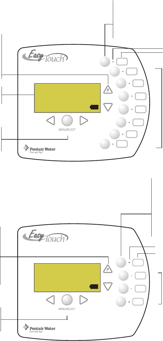
For details about the
control panel LCD status
messages, see page 8
Circuit LED
Circuit name label
7 User defined auxiliary
circuits. Buttons switch
the assigned circuit
function on/off
(12 hour time-out)
Spa (Hi-Temp) Button: Switches the filter
pump on, rotates valve actuator (to isolate spa
water from pool water), and switches the
heater on. Hi-Temp (EasyTouch single body
system) sets the high temperature settings for
the spa (see page 26)
Circuit LED
Circuit name label
Spa (Hi-Temp) Button:
Switches the filter pump on,
rotates valve actuator (to
isolate spa water from pool
water), and switches the heater
on. Hi-Temp (EasyTouch single
body system) sets the high
temperature settings for the
spa (see page 26)
Pool (Lo-Temp) Button: Switches
the filter pump on, rotates valve
actuator (to isolate pool water from
spa water), and switches heater on.
Lo-Temp (EasyTouch single body
system) sets the low temperature
settings for the pool (see page 26)
Pool (Lo-Temp) Button:
Switches the filter pump on,
rotates valve actuator (to isolate
pool water from spa water), and
switches heater on.
Lo-Temp (EasyTouch single
body system) sets the low
temperature settings for the pool
(see page 26)
3 User defined auxiliary
circuits. Buttons switch
the assigned circuit
function on/off
(12 hour time-out)
EasyTouch Wireless Control Panel (8 circuits) - (P/N 520547)
EasyTouch Wireless Control Panel (4 circuits) - (P/N 520546)
Menu/Select and Power
On button (see page 7 for
details)
Menu/Select and Power
On button (see page 7 for
details)
AUTO HEATER
SPA 95°F / 100°F
AIR 70°F
MON 09:30 AM
AUTO HEATER
SPA 95°F / 100°F
AIR 70°F
MON 09:30 AM
POWER ON
POWER ON
6
EasyTouch Wireless Control Panel User’s and Installation Guide
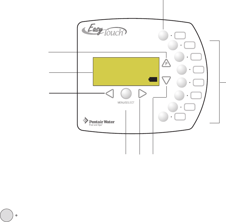
EasyTouch Wireless Control Panel Buttons
Spa button/LED: For spa operations. Press this button to rotate valves and activate the filter pump
automatically so that only the spa water is circulated through the system. If the heater is enabled,
pressing this button also switches the heater on (if enabled in the Heat menu). When this button is
pressed the circuit is activated, the LED is on and “SPA” is displayed on the screen with the current
and set point water temperatures. The default time before the filter pump will switch off is 12 hours.
When this button is pressed, the LEDs on the outdoor control panel Filter Pump (F) button, Valves
(V) button, and Heater button (if enabled in the Heat menu) will be on.
Pool Button: For pool operations. Press this button so that only the pool water is circulated through
the system. Note that the filter pump will switch off while the pool/spa valves are rotating into
position. If the heater is enabled, pressing this button also switches the heater on (if enabled in the
Heat menu). When this button is pressed the circuit is activated and “POOL” is displayed on the
screen with actual and set point water temperatures. The default time before the filter pump will
switch off is 12 hours. When this button is pressed, the LEDs on the outdoor control panel Filter
Pump (F) button, Valves (V) button, and Heater button (if enabled in the Heat menu) will be on.
➀
➁
EasyTouch Wireless Control Panel Buttons
You can fully automate your pool, spa, and lighting operations from the EasyTouch wireless control panel or
from the outdoor control panel located at the pool equipment pad. The EasyTouch menu options lets you create
customized schedules for your pool and spa equipment, heat temperatures, and chlorination settings to switch
on and off at a set day and time. Scheduled automatic operations can be performed at the EasyTouch wireless
control panel or from the outdoor control panel. For menu options, refer to “EasyTouch Menu Structure,” on
page 15. Before operating the EasyTouch wireless control panel, familiarize yourself with the LCD status
messages and operating buttons.
U
P
EasyTouch Wireless Control Panel
➁
➅➆
➇
➀
➃
➂
➄
AUTO HEATER
SPA 95°F / 100°F
AIR 70°F
MON 09:30 AM
POWER ON

7
EasyTouch Wireless Control Panel User’s and Installation Guide
Controls and buttons (Continued)
Pool button (Continued)
•Single-Speed Filter Pump: If the pump is currently off, press the Pool button to switch the pump
on. Press the Pool button again to switch the pump off. However, if the heater is operating, and a
delay is enabled for valves, this allows the heater to cool down (heater cool-down), then when you
press the Pool button to switch off the pump, only the heater will turn off, then the filter pump will
automatically switch off after 10 minutes to allow the heater to cool down. Pentair heaters do not
require a cool down time. To override the heater cool-down process, press the Pool button again to
switch off the pump.
•Two-Speed Filter Pump: Press the Pool button to switch the two-speed pump on in high speed.
Press the Pool button again to run the pump in low speed. In order to use the “2-Speed Pump” menu
assignments (see page 31), the 2-Speed relay option must be installed in the EasyTouch Load
Center.
Notes about Freeze Protection: This function protects the pool, plumbing, and equipment against
freeze damage. If the outside air temperature sensor falls below 36° F, “Freeze Protection” is
activated and the Filter Pump relay is switched on to circulate the pool water. To enable freeze
protection for a circuit, see “Settings Menu: Circuit Types, ” on page 28.
Liquid Crystal Display (LCD): The main system display consists of a 16 x 4 alphanumeric character
LCD with EL backlighting for easy viewing of the menu items, and status messages. Press the
Menu/Select button twice to refresh the display. For EasyTouch main screen status information, see
page 5. For details about the battery status icon, see page 2.
Left button: Use the Left button to scroll through sub-menu selections, setting and values. While
editing settings, press and hold the Left button to fast reverse through settings and values.
Menu/Select and Power On button: This button has two functions; to access the menu options and
switch power on to the unit. The unit can be manually switched off using the “Power Off” menu
option (see page 41 for details). Use the Menu/Select button to access the EasyTouch menu system,
save and exit settings. Control panel buttons are disabled while in the menu. Use this button to exit
from main menu or sub-menu items. Pressing the Menu/Select button while in a menu item will
return to the main screen. If no menu activity is detected after five minutes, the main screen is
displayed. All menu settings are permanently saved and retained in the control panel even after
power is removed from the control panel.
AUX buttons/LEDs: The auxiliary output circuit buttons operate the pool and spa system valves,
lights and other equipment. These auxiliary (AUX) circuits are assigned in the “Circuit Type” menu,
see page 280 for details. There are three auxiliary circuits (AUX 1- 3) available on the EasyTouch 4
and seven auxiliary circuits (AUX 1- 7) on EasyTouch 8. Labels can be affixed next to each
auxiliary button to identify the circuit function. When an auxiliary circuit is activated or the button is
pressed, the LED is on. Pressing an auxiliary circuit button will activate the corresponding circuit in
either “Auto” or “Service” mode. When a circuit relay is switched on manually, it remains on until
either you switch it off manually, or the next time the relay is scheduled to be switched off. For
example, if the filter pump is scheduled to automatically run from 9:00 AM to 5:00 PM daily then the
filter pump is switched on manually at 9:00 PM, it will run continuously until the next day at 5:00 PM
then switch off. The schedule will then continue from then on.
➄
➅
➂
➃Y
MENU/SELECT
POWER ON
8
EasyTouch Wireless Control Panel User’s and Installation Guide
➆
➇
V
U
Z
Controls and buttons (Continued)
Right button: Use the Right button to select a sub-menu item for editing. After pressing the Menu
button to access the main menu items, use the Right button to select the menu item and access the
sub-menu items for adjustment. For convenience, while editing a settings, press and hold the Right
button to fast forward through settings and values.
Up/Down buttons: Use the Up and Down buttons to scroll through the main menu items and to
adjust or change settings. Use these buttons after pressing the Menu/Select button to access the
main menu items. While editing settings, press and hold the Up or Down button to fast forward or
fast reverse through settings and values.
EasyTouch Wireless Control Panel Display
The EasyTouch wireless control panel screen displays when the system is in automatic mode (AUTO) or in
service mode (SERVICE). Service mode is enabled from EasyTouch outdoor control panel at the pool
equipment pad. The following describes the main status screen.
AUTO (Automatic): The system is in normal operating mode.
Scheduled programs will run automatically.
HEATER: Displays the heat source (Off, Heater, Solar Prf.,
Solar) as specified in the Heater menu settings (see page 18).
POOL (Spa): Indicates that the Valves (V) button is in “Pool” or
“Spa” mode and the Filter Pump (F) button has been pressed to
switch on the filter pump. If this display line is blank, it indicates
no spa or pool function is active. For an EasyTouch single body
system, Hi-Temp (Spa) / Lo-Temp (Pool) sets the temperature
settings (see page 26)
95° F / 100° F: Displays the actual spa or pool water temperature
(95° F) and the set point temperature (100° F) as set in the
“Heater” menu.
AIR: Displays the actual outside air temperature (70° F) as read
by the air sensor located near the EasyTouch Load Center.
Date and Time: Displays the EasyTouch system day and time as
specified in the “Clock” menu settings (see page 24).
AUTO HEATER
SPA 95°F / 100°F
AIR 70°F
MON 09:30 AM
POWER ON

9
EasyTouch Wireless Control Panel User’s and Installation Guide
Switching Power On
Use the POWER ON button located on the front of the EasyTouch wireless control panel to power up the
unit. Each time after batteries are installed in the unit, after powering up, a check message prompt is displayed.
Press the Up button to continue to display the main status screen. The unit is ready for operation.
Quick Start Spa and Pool Operations
The following describes how to run some of the general day-to-day spa and pool operations.
Heat your spa or pool
First enable the heat source in the Heat menu (see “Heat Menu,” on page 18). Press
the Spa button (top button) to switch the filter pump on, rotate the valve actuator (to
isolate spa water from pool water), and switch the heater on. Note: By default, the
setting “Man Heat’ is set to “On” (see page 35) which allows the spa to begin to
heat whenever it is manually turned on. Press the Pool button to switch the filter
pump on, rotate the valve actuator (to isolate pool water from spa water), and switch
the heater on. For Pool and Spa button location, see page 5.
Adjust your spa or pool heat settings
From the “Heat” menu (Menu/Select > Heat > Spa Temp/Src/Pool Temp/Src) you can select the heat
source and set the water temperature. The spa or pool water will heat to the settings specified. The
EasyTouch system allows for solar and conventional heaters. The EasyTouch will use the heating source that
is selected. The heat source selections are:
•OFF - No heating even though pump and other circuits may be operating.
•HEATER - Gas heater only.
•SOLAR ONLY - Solar heating system to be the only heat source. In order to display “Solar Only” as a
heat option in the “Heat” menu, you must first enable solar in the Settings > Solar menu
(see page 31).
•SOLAR PREF. (Solar Preferred) - Used if solar and gas heating are combined and you want to use
solar heating only when it is most effective. In order to display “Solar Preferred” as a heat option in
the “Heat” menu, you must first enable solar in the Settings > Solar menu (see page 31).
To set the spa temperature set point and select the heat source:
Right button: Select spa temperature and heat source.
Up/Down button: Adjust the spa water temperature.
(from 40° F to 106° F or 4° C to 41° C).
Right or Left button: Move to Heat source options.
Up/Down: Set the Heat option: Off, Heater, Solar, or Solar Preferred.
Menu/Select: Press this button save settings and to return to the Heat menu or press
the button again to return to the Main screen.
Note: Select “Pool Temp/Src” to adjust your pool temperature.
Pool Temp/Src
Spa Temp/Src
X
T
S
Spa
Temp: 85° F
Heat: Off T
S
Getting There
▼ HEAT
AUTO HEATER
SPA 95°F / 100°F
AIR 70°F
MON 09:30 AM

10
EasyTouch Wireless Control Panel User’s and Installation Guide
Switch on lights manually
From the Lights screen you can manually switch all lights on or off, and synchronize colored lights. Up to 12
lights can be controlled. For more information about setting up lights, refer to “Lights Menu” on page 17.
To manually switch on all lights:
Up/Down button: Select: All off, All on, or Sync. The Sync feature allows a
combination of up to 12 SAm, SAL, or FIBERworks lights to synchronize their colors
before switching the lights on.
Menu/Select: Press this button save settings and to return to the main menu items or
press the button again to return to the Main screen.
Using the Once Only timer feature
The Schedules “Once Only” timer feature enables you to automatically switch equipment on for one time. This
feature allows you to program a circuit to turn on at a particular time on a one-time basis. For example, if you
wanted the spa to be heated when you arrive home, you could program the heater to switch on at a specific
time and after you have finished using the spa you can switch the heater off manually. After the program has
run, it is automatically erased. Unlike using the regular “Schedule” program, the “Once Only” program does
not repeat. The circuit must be turned off manually or wait for the 12 hour automatic shut-off. However, you
could also reset the 12 hour factory shut-off by entering an “Egg Timer” count down program to extend past
the default 12 hours shut-off.
The following example describes how to set a “Once Only “ program for the spa. The same steps apply when
selecting the pool or any auxiliary circuit.
Right button: Select the Spa circuit.
Right button: Select Mode if there are existing programs. Skip this step to create a
new program.
Up/Down button: Select New to create a new program.
Right button: To create a new program and enter the “Mode” settings.
Up/Down button: 1/1 indicates that this circuit has one program. If there are existing
programs assigned to this circuit, use these buttons to view and select the existing
program settings.
Right button: To select the “Once Only” settings.
Right button: Move to start time settings.
Up/Down and Right buttons: Set the start hour (A/P) and minutes. A (AM) and
P (PM) time is set when setting the start hour.
Right button: Move to day of the week to run the program.
Right button: Select which day to run the program then press the Up/Down button
to enable the bar on top of the letter. A bar on top of the letter indicates the day
selected to run the program.
Menu/Select: Press this button to save settings and to return to the Schedules menu
options. Press the button again to return to the main menu options or press again to
return to the Main screen.
Setup Lights
Mode: All Off
T
S
Getting There
LIGHTS SET UP LIGHTS
▲
Getting There
▼ SCHEDULES SPA
▲
Spa 0/0
Mode: None (New)
S
Spa 0
Pool 0
Aux 1 0
Aux 2 0 T
S
X
Spa 1/1
Mode: Once Only
08:00A
s m t w t f s T
S
_
11
EasyTouch Wireless Control Panel User’s and Installation Guide
Schedule start and stop times for equipment
You can set timers (schedules) to automatically run equipment like pool filtration or lights. Any EasyTouch
circuit can be set to switch on and off on every or any day of the week. Up to 12 total programs may be
created for all circuits combined.
Program your Spa or Pool
You can use the “Schedule” feature to set the time and day(s) when to switch the filter pump on and rotate the
pool/spa valves into the “Pool” or “Spa” position. The heater will automatically heat the pool or spa water up
to the set point temperature as set in the “Heat” menu (see page 11). If the pool has a separate jet pump or
blower controlled by AUX 1 and/or AUX 2 , these need to be scheduled separately.
Schedules
To create a schedule for your spa or pool:
Right button: Select the Spa circuit.
Right button: Select Mode if there are existing programs. Skip this step to create a
new program.
Up/Down button: Select New to create a new program.
Right button: To create a new program and enter the “Mode” settings.
Up/Down button: 1/1 indicates that this circuit has one program. If there are existing
programs assigned to this circuit, use these buttons to view and select the existing
program settings.
Right button: To select the “Schedule” settings.
Right button: Move to start and stop time settings.
Up/Down and Right buttons: Set start and stop hour (A/P), minutes.
The A (AM) and P (PM) time is set when setting the start and stop hour.
Right button: Move to days of the week to run the program.
Right and Up/Down buttons: By default the program is set to run all the days of
the week. If you wish to edit which days to run the program, select the day of the
week, then press the Up/Down button to remove the bar from the top of the letter. A
bar on top of the letter indicates the day selected to run the program.
Menu/Select: Press this button to save settings and to return to the Schedules menu
options. Press the button again to return to the main menu options or press again to
return to the Main screen.
Getting There
▼ SCHEDULES SPA
▲
Spa 0/0
Mode: None (New)
S
Spa 0
Pool 0
Aux 1 0
Aux 2 0 T
S
X
Spa 1/1
Mode: Schedule
08:00A - 05:00P
s m t w t f s T
S
_ _ _ _ _ _ _

12
EasyTouch Wireless Control Panel User’s and Installation Guide
Setting the Egg Timer Feature
The “Egg Timer” feature lets you manually switch on equipment program the system to automatically switch
off after a specified time. You can set this timer feature for other equipment such as lighting, spa, or spa jets.
Equipment can be set to be on for one minute to 24 hours. An Egg Timer program is factory set to switch off
after 12 hours. You also have the option to use the “Don’t Stop” feature to run a circuit continuously until
manually switched off.
Please note that in the event of a power failure, the Egg Timer feature will not switch the circuit back on. Use
the “Service” mode to turn the equipment back on. For more information, refer to the “EasyTouch User’s
Guide (P/N 520584).
Note: When running the filter pump continuously during a new pool start up, it is recommended to use
the “Service” mode, which will automatically restart the filter pump in the event of a power failure.
To set the Egg Timer feature:
Right button: Select the Spa circuit.
Right button: Select Mode.
Up/Down button: Select New to create a new program.
Right button: To create a new program and enter the “Mode” settings.
Up/Down button: 1/1 indicates that this circuit has one program. You create a total
of 12 programs. If there are existing programs assigned to this circuit, use these
buttons to view and select the existing program settings.
Right button: To select the “Egg Timer” settings.
Right button: Move to the time settings.
Up/Down and Right buttons: Set the hour and minutes for the program to run. The
count down time can be set from 00:01 to 23:59 and Don’t Stop. The “Don’t Stop”
feature allows the circuit to run continuously until manually switched off.
Menu/Select: Press this button to save settings and to return to the Schedules menu
options. Press the button again to return to the main menu options or press again to
return to the Main screen.
Spa 1/1
Mode: Egg Timer
Time: 05:00
T
S
Getting There
▼ SCHEDULES SPA
▲
Spa 0/0
Mode: None (New)
S
Spa 0
Pool 0
Aux 1 0
Aux 2 0 T
S
X

13
EasyTouch Wireless Control Panel User’s and Installation Guide
Section 2
Setting up EasyTouch
Setting up the System for the First Time
Use the following steps if you are setting up the EasyTouch system for the first time.
Note: The following setup steps assume that the EasyTouch Load Center is installed at the equipment
pad and ready for operation. For EasyTouch Load Center installation instructions, refer to the
EasyTouch 8 and 4 Load Center Installation Guide (P/N 520583).
The recommended first time installation steps for the EasyTouch system are:
1. Set the system date and time (page 24)
Use the “clock” menu option to set the current date and time for the EasyTouch system.
2. Assign circuit names (pages 26)
Assign the generic default circuit names for output auxiliary equipment. Rename (if necessary) and assign
circuit names to the auxiliary (AUX 1, AUX 2) connections. Note the factory set auxiliary names correspond
to the plug-in location of the relay on the EasyTouch motherboard. Assign circuit names from the available of
circuit names. There are nearly 100 circuit names available (see page 27 for the complete list).
3. Creating custom names for auxiliary circuits (page 30)
If you cannot find a circuit name that fits your application you can create up to 10 additional customized
names that can be created before assigning circuit names.
4. Assign a circuit type to a circuit name (Page 28)
Assign “Circuit Types” (functions) to circuits. From the Circuit Type menu, you can assign special logic to a
circuit by selecting one of the available circuit types. For the complete list of Circuit Types. If an auxiliary
circuit (AUX) is assigned GENERIC (simple ON/OFF when the button is pushed) then nothing needs to be
done.
5. Configure valve actuators (controlled by AUX circuit) (page 30)
The EasyTouch system can drive two auxiliary valve actuators for applications such as solar heating and
water features. Assign which circuits that will activate valves A and B. Auxiliary valve actuators can be
controlled by any AUX circuit. Valve A is automatically assigned to solar if “Solar” is enabled in the “Solar”
menu.
14
EasyTouch Wireless Control Panel User’s and Installation Guide
6. Set up optional equipment, solar, 2-speed pump (page 31 and 32)
Set up additional equipment such as solar, 2-speed pump, and optional equipment if required. Set up the
control panel to operate with the optional IntelliChlor chlorine generator. To configure EasyTouch for special
equipment:
• Is solar heating available? Is solar being used for a heat pump?
• What circuits will turn 2-Speed pumps to High Speed?
• Cool-down cycle for the heater - Lets you set circuits that switch the filter pump to high speed.
• Do you want to delay turning off the filter pump for 10 minutes when the heater is turned off?
• Do you want the spa to heat whenever the Spa button is pressed?
7. Configuring the heater system options (page 18)
Set the type of heat source being used (Heater, Solar, Solar Preferred).
8. Configure the iS4 spa-side remote, QuickTouch wireless remote buttons (page 33 and 34)
Assign four circuits to the iS4 and/or QuickTouch remote buttons. Once you have checked that all buttons
operate properly, place labels on remote buttons.
9. Set the delays feature (page 32)
Enable the one time “delay” feature for the heater, 2-speed pump, and automatic pool cleaner.
10. Schedule on/off times for circuit (page 21 - 23)
Set times for automatic circuit activation. Up to 12 total programs can be created for all circuits combined.
One circuit can have up to a maximum of 9 programs (9/9), which leaves 3 programs that can be used by one
circuit or three separate circuits for a total of 12 programs. All user created programs are active all the time;
so check that there are not conflicting automated times.
11. Setup the lighting settings (page 17)
From the lighting menu you can enable special control of your pool and yard lighting, such as rotating colored
lights, and synchronized colored lights.
15
EasyTouch Wireless Control Panel User’s and Installation Guide
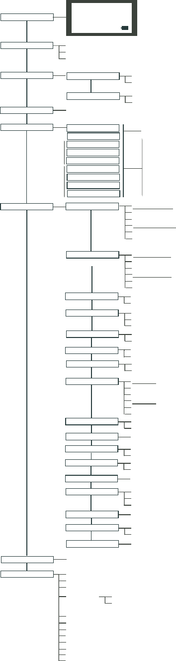
EasyTouch Menu Structure
MAIN SCREEN
AUTO HEATER
SPA 100˚ F / 95˚F
AIR 70˚F
MON 09:30 AM
LIGHTS All On (Switch all lights on)
All Off (Switch all lights off)
Sync (Synchronize colored lights)
HEAT
DIAGNOSTICS Software Rev (Revision level for main control panel and Indoor Control Panel)
Bootloader Rev (Revision level for main control panel and Indoor Control Panel)
Self Test (Status: Testing (follow on-screen prompts to test LCD and buttons) - Code: 0 - see "Troubleshooting" section for error codes)
Water Temp (Fahrenheit/Celcius - Status display only)
Solar Temp (Fahrenheit/Celcius - Status display only) - (Displays if Solar is enabled in Heat menu)
Air Temp (Fahrenheit/Celcius - Status display only)
Pool Temp/Src Temp (40˚ F - 106˚ F) or (4˚ C - 41˚ C)
Heat (Off/Heater/Solar/Solar Prf) - Solar/Solar Prf must be enabled in "Solar" menu to display.
Spa Temp/Src Temp (40˚ F - 106˚ F) or (4˚ C - 41˚ C)
Heat (Off/Heater/Solar/Solar Prf) - "Solar/Solar Prf" must be enabled in "Solar" menu to display.
DELAY CANCEL
Mode: Schedule
08:00A -- 05:00P (12:00 AM - 11:59 PM -12 hours)
s m t w t f s (days of the week)
SCHEDULES
SPA 0
AUX 2 0
AUX 4 0
AUX 3 0
Mode: Egg Timer
Time: 12:00 (00:00 - 23:59) / DON'T STOP
SETTINGS
IntelliChlor
Enable (No/Yes)
Level (0% - 100%)
IntelliChlor 2/2
Run Hours (0 -72)
IntelliChlor 1/2
Super Chlr (On/Off)
(Optional)
Circuit Names
Circuit (Spa, Pool, AUX 1-3 (ET 4) - Spa, Pool AUX 1 - 7 (ET 8) Refer to "Circuit Names" on page 30
Circuit Names 1-9 (Assign names for up to 9 circuits)
Circuit Types Circuit (Spa [MASTER SPA], Pool [MASTER POOL], AUX 1-7 (AUX 1-3), Generic, Master Spa, Master Pool, Mstr Cleaner,
Freeze: No/Yes
Custom Names Cstm Name 1/10 (Assign up to 10 custom names)
[USERNAME-01...10] (up to 11 alphanumeric characters)
2-Speed Pump
Circuit (None, Spa, Pool, AUX 1 - 3 (ET 4) - Spa, Pool, AUX 1 - 7 (ET 8), Solar, Heater, Pool Heater, Spa Heater, Freeze)
2-Speed Pmp 1/4 (Assign up to 4 circuits)
Solar
Delays Pool/Spa (Yes/No)
Valves (Yes/No)
Enable (Yes/No)
Heat Pump (Yes/No)
Solar 2/2 (Tempreature Difference)
Run (2˚-5˚)
Solar 1/2
Start (3˚-9˚)
Valves
Clock
F˚ / C˚
iS4
FAHRENHEIT / CELCIUS
Quick Touch Assign QT4 1/4 (Assign up to 4 circuits)
Circuit - (None, Spa, Pool, AUX 1 - AUX 7 (ET 8), AUX 1 - AUX 3 (ET 4), HEAT BOOST, HEAT ENABLE)
Erase EEPROM Erase all (Yes /No) - Are you sure? (Yes/No)
Circuit - (None, Spa, Pool, AUX 1 - AUX 7 (ET 8), AUX 1 - AUX 3 (ET 4), HEAT BOOST, HEAT ENABLE)
Assign iS4 1/4 (Assign 4 circuits)
Calibration
Air (Fahrenheit/Celcius)
Solar (Fahrenheit/Celcius) - Solar must be enabled in "Heat" menu to display
Water (Fahrenheit/Celcius)
Date & Time 1/2
June 22 2005 (Month/Day/Year)
WED 11:00 AM (Day/Hour/Minutes/AM/PM)
Date & Timer 2/2
Daylight Saving: (Auto/Manual)
Clock Adjust 00:00 (0 to 300) - (-300 to -5) in 5 sceond increments
(Delayed Cancelled) Press Right button to activate
A: [None, Spa, Pool, AUX 1 - 3 (ET 4) - Spa, Pool, AUX 1 - 7 (ET 8), Heater] - (USED SOLAR if Solar is enabled)
B: [None, Spa, Pool, AUX 1 - 3 (ET 4) - Spa, Pool, AUX 1 - 7 (ET 8), Heater]
Disp Op Codes - Display? No/Yes (Displays transmit/receive packets numbers on screen)
SPA SIDE [Off/On]
POOL 0
AUX 1 0
AUX 5 0
AUX 6 0
AUX 7 0
Enable/Disable iS4 Spa-Side remote
Light, SAM light, SAL Light, Photon Generator, Color Wheel, Spillway, Floor Cleaner (see page 32 for details)
Cir Names [On/Off] View default circuit names before modification.
Chlorinator Salt Level: Displays current salt level (xxxx) ppm
Status: OK - NO ERRORS (SUPER CHLORINATE, COM LINK ERROR, CHECK FLOW / PCB,
LOW SALT, VERY LOW SALT, HIGH CURRENT, CLEAN CELL!!, LOW VOLTAGE)
Man Heat [Off/On] Switch manual heat on or off when spa is manually switched on (Use Right button select On/Off)
EasyTouch 4
EasyTouch 8 Mode: Once Only
08:00A (12:00 AM - 11:59 PM -12 hours)
s m t w t f s (select day of the week to run program)
Mode: New / Delete / None
Reset System (Reinitialize Indoor Control Panel - use Right button)
Hi-Temp (Spa) / Lo-Temp (Pool) for single body system (see Settings Menu: Circuit Names)
Flash Update (Use for future firmware updates via PC - Press MENU to abort)
Power OFF (Manually switch's off the unit - Press the Power ON button to switch unit on)
Power Save Options Idle Time: 30 S, 60 S, 5 M
Backlight Options
Brightness: LOW, MED HI
On Time: 30 S, 60 S, OFF

16
EasyTouch Wireless Control Panel User’s and Installation Guide
EasyTouch Menus
Use the EasyTouch control panel menus to schedule when to heat and filter your pool and spa automatically.
Lights can also be switch on and off. The main screen shows the pool (or spa), temperatures and the system
day and time. The main screen is automatically displayed if there is no menu control panel activity for five
minutes.
The “Settings” and “Schedule” menus are typically used most often for daily spa and pool operations. The
“Settings” menu is used by the pool installer to setup installed equipment which is connected to each output
relay (filter pump, auxiliary relays, heater, valves, lights, etc.). For EasyTouch equipment installation
instructions, see the EasyTouch Installation Guide (P/N 520584).
Main Screen
The main screen shows the mode of operation (AUTO/SERVICE), the heat source
being used. The spa (or pool) actual water temperature (95° F) and the current heater
set point temperature (100° F) are displayed. The current air temperature is also
displayed in either Fahrenheit or Celsius. If the second display line is blank and the
heat source is not displayed, there is no spa or pool function currently active. If the
IntelliChlor salt chlorinator generator option is installed, pool and spa sanitizer settings,
and salt level is shown in the Diagnostics, “Chlorination,” settings.
Main Screen Description
AUTO: EasyTouch is in normal (automatic) operating mode.
HEATER: The selected heat source as selected in the “Heat” menu (see page 18). The heat options are:
•OFF - No heating even though pump and other circuits may be operating.
•HEATER - Gas heater only.
•SOLAR ONLY - Solar heating system to be the only heat source. In order to display “Solar Pref.” on
the main screen, you must first enable solar in the “Solar” menu (see page 31).
•SOLAR PREF. - (Solar Preferred) - For when solar and gas heating are combined, and you want to
use solar heating only when it is most effective. In order to display “Solar Pref.” on the main screen,
you must first enable solar in the “Solar” menu (see page 31).
SPA: “SPA” is displayed after the “Spa” button has been pressed to switch the filter pump on, rotate the valve
actuator (to isolate spa water from pool water), and switch the heater on (if enabled in the “Heat” menu). The
temperature unit displayed on the left side is the actual water temperature (95° F) and the set point
temperature (100° F) as set in the “Heat” menu is displayed on the right side. Degree units are displayed in
either Fahrenheit or Celsius (see page 33). If this display line is blank, it indicates no spa or pool function is
currently active.
POOL: “POOL” is displayed after the “P” button has been pressed to switch the filter pump on, rotate the
valve actuator (to isolate pool water from spa water), and switch the heater on (if enabled in the “Heat”
menu). The temperature unit displayed on the left side is the actual water temperature (95° F) and the set
point temperature (100° F) as set in the “Heat” menu is displayed on the right side. Degree units are displayed
in either Fahrenheit or Celsius (see page 33). If this display line is blank, it indicates no spa or pool function is
currently active.
AIR: Displays the actual outside air temperature (70° F) as recorded by the air sensor located near the
EasyTouch load center. Degree units are displayed in either Fahrenheit or Celsius (see page 33).
DAY and TIME: The current system day and time (AM/PM). See the “Clock” menu to set the system day and
time (page 24).
AUTO
AIR 70°F
MON 09:30 AM
AUTO HEATER
SPA 95°F / 100°F
AIR 70°F
MON 09:30 AM

17
EasyTouch Wireless Control Panel User’s and Installation Guide
Lights Menu
From the Lights screen you can manually switch all lights on or off, and synchronize colored lights. If you
have at least two Pentair SAm and/or SAL, and/or FIBERworks lighting systems you can use the Sync feature
to change the lighting settings. This feature require a separate auxiliary relay circuit for each light. Up to four
lights can be assigned on each auxiliary circuit for a total of 12 lights that can be independently controlled from
the Lights menu.
Make sure the AUX relay circuits which control your lighting have been assigned names. Then verify that
SAm and/or SAL, and/or FIBERworks have been set up in “Circuit Types” as SAM or SAL lights. If
FIBERworks lighting is incorporated, it also has to be set up as a “PHOTON GENERATOR” for the circuit
controlling the light bulb, and COLOR WHEEL for the circuit controlling the color wheel. For more
information about setting up lights, see “Settings Menu: Circuit Types,” on page 28.
Lights
To configure lights:
Up/Down button: Select: All off, All on, or Sync.
Menu/Select: Press this button save settings and to return to the main menu items or
press the button again to return to the Main screen.
The lights options are:
All Off: Switch all lights off manually.
All On: Switch all lights on manually.
Sync: Causes all colored lights to synchronize their colors.
Setup Lights
Mode: All Off
T
S
Getting There
LIGHTS SET UP LIGHTS
▲
18
EasyTouch Wireless Control Panel User’s and Installation Guide
Heat Menu
Use the heat menu settings to specify the set point temperature and select the heat source for the pool and spa
water. The water will begin to heat whenever the heater is manually switched on, (by pressing the “Pool” or
“Spa” button or the Valves (V) button outdoor control panel), even if the heater is set to off. The spa will also
begin to heat when switched on by the optional iS4 Spa-Side remote, or EasyTouch wireless remote. The
EasyTouch system allows for solar and conventional heaters. The EasyTouch will use the heating source that
is selected. The heat source selections are:
•OFF - No heating even though pump and other circuits may be operating.
•HEATER - Gas heater only. Use the Heater button to automatically switch the heater on which
controls the output between a “forced off” state and a normal, automatic thermostatic control
operating state. The heater will continue heating the water until the heater’s current highest set point
temperature triggers the heater sensor (approximately 106° F or 41° C). Note that the Heater button
on the control panel does not activate the pump. Do not activate the heater without running the pump.
The heater will not run if water flow is not detected.
•SOLAR ONLY - Solar heating system to be the only heat source. In order to display “Solar Pref.” on
the main screen, you must first enable solar in the “Solar” menu (see page 31).
•SOLAR PREF. (Solar Preferred) - Solar and gas heating systems are installed, and you want to use
solar heating only when it is most effective. In order to display “Solar Pref.” on the main screen, you
must first enable solar in the “Solar” menu (see page 31). To set the spa temperature and select the
heat source:
Pool Temp/Src
To set the pool temperature and select the heat source:
Right button: Select pool temperature and heater options.
Up/Down button: Set the pool temperature (from 40° F to 106° F).
Right or Left button: Move to Heater option.
Up/Down: Set Heater option: Off, Heater, Solar, or Solar Preferred.
Menu/Select: Press this button save settings and to return to the previous menu or
press the button again to return to the Main screen.
Spa Temp/Src
To set the spa temperature and select the heat source:
Right button: Select spa temperature and heater options.
Up/Down button: Set the spa temperature (from 40° F to 106° F or 4° C to 41° C).
Right or Left button: Move to Heater option.
Up/Down: Set Heater option: Off, Heater, Solar, or Solar Preferred.
Menu/Select: Press this button save settings and to return to the Heat menu or press
the button again to return to the Main screen.
Spa
Temp: 85° F
Heat: Off T
S
Getting There
▼ HEAT
Pool
Temp: 72° F
Heat: Off T
S
Pool Temp/Src
Spa Temp/Src
T
S
X
Pool Temp/Src
Spa Temp/Src
X
T
S
Note: For an EasyTouch single body system, “Pool” and “Spa” modes are Lo- Temp (Pool) and
Hi-Temp (Spa) temperature controls. For more information, see “Hi-Temp/Lo-Temp Controls for Single
Body Systems,” on page 26.

19
EasyTouch Wireless Control Panel User’s and Installation Guide
Delay Cancel Menu
Use the Delay Cancel feature for service or testing purposes. For convenience, on a one-time basis, the Delay
Cancel feature will cancel the following safety delays. Please note, generally there is no need to cancel any of
the following delays except for servicing or testing the system.
•Heater Cool-Down Delay Cancel: Shuts Filter Pump off immediately.
•2-Speed Filter Pump five-minute START on HIGH SPEED Delay Cancel: Shifts pump to low
speed.
•Automatic Pool Cleaner START Delay: Starts Cleaner Pump immediately, without normal delay in
which the filter pump first runs for 5 minutes.
•Automatic Pool Cleaner SOLAR Delay: Allows Cleaner Pump to run even though solar delay has
shut it off for 5 minutes.
Some heaters require a cool-down cycle before being switched off. This can be setup in the menu to run the
filter pump an additional ten minutes to dissipate residual heat built up inside the heater combustion chamber.
The Delay Cancel feature is mainly for use by service technicians when it’s necessary to shut the filter pump
off immediately, and know the heater has not been running. Heaters manufactured by Pentair do not require
this cool-down period and do not need the delay to be set up.
Note: For Information about assigning delays to the pool and spa valves, refer to “Settings Menu:
Delays” on page 32.
Delay Cancel
To activate Delay Cancel:
Up/Down button: Select Delay Cancel.
Right button: Use this button activate Delay Cancel for one time only. “Delay
Cancelled” is displayed after pressing the Right button.
Menu/Select: Press this button to return to the Main screen.
Getting There
▼ DELAY CANCEL
▲
Lights
Heat
Delay Cancel
Schedules T
S
X

20
EasyTouch Wireless Control Panel User’s and Installation Guide
Schedules Menu
Use the “Schedules” menu to create programs that automatically run equipment like pool filtration or lights.
Any circuit can be programmed to switch on and off at a specific time on every or any specific day of the
week. The number of programs that can be created for circuits are as follows:
• Up to 12 total programs can be created for all circuits combined.
• One circuit can have up to a maximum of 9 programs (9/9), which leaves 3 programs that can be
used by one circuit or three separate circuits for a total of 12 programs.
Using the Schedules menu
Use the “Schedules” menu to program operating schedules for the pool, spa and auxiliary circuits:
Choose the circuit to program
Up/Down button: Select the circuit (generic names shown) to program: Spa, Pool,
AUX 1 - AUX 3 (EasyTouch 4), AUX 1 - AUX 7 (EasyTouch 8).
The current number of programs for each circuit is displayed opposite the circuit
name. A circuit can have up to 9 programs (9/9). Three additional programs can be
assigned to another circuit or three separate circuits for a maximum of 12 programs.
Create a new program
The current number of programs for each circuit is indicated opposite to the circuit
name. 0/0 indicates no programs assigned to this circuit.
Right button: To move to the “Mode” selection.
Up/Down button: Select New to create a new program. Use “None” when a circuit
has existing programs and you wish to exit the “Mode” selections without modifying
the existing programs.
Choose the type (Mode) of program to run
After selecting “New” the current program number (1/1) for this circuit is displayed.
Right button: To move to the “Mode” selections.
Up/Down button: Choose the program to run: Schedule, Egg Timer, Once Only,
New, Delete, and None. If there are existing programs assigned to this circuit, use
these buttons to view and select the existing program settings.
Mode Selection:
Schedule: Set start, stop times and the day(s) of the week to automatically switch
pool/spa circuits on or off. Default run time for the “Schedule” feature is 8:00 AM to
5:00 PM. If you program the start and stop times the same the schedule is will run for
24 hours.
Egg Timer: A one time program that switches on a function at a specific time, and
counts down the pre-set time to the switch off the function. After the “Egg Timer”
schedule has finished, the system can be operated in manual mode. The “DON'T
STOP” option allows a circuit to run continuously until its switched off manually.
Once Only: Schedule a circuit to switch on at a particular time on a one-time basis.
New: press the Right button to create a new program.
Delete: Select the program and press the Right button to delete it.
None: Press the Right button to exit the “Mode” selections without modifying the
program.
Spa 0/0
Mode: None
S
Spa 0
Pool 0
Aux 1 0
Aux 2 0 T
S
X
Spa 1/1
Mode: Egg Timer
Timer: 12:00
T
S
Spa 1/1
Mode: Once Only
08:00A
s m t w t f s T
S
_ _ _ _ _ _ _
Spa 1/1
Mode: Schedule
08:00A - 05:00P
s m t w t f s T
S
_ _ _ _ _ _ _
Spa 1/1
Mode: Delete
T
S
Spa 1/1
Mode: None
T
S
Spa 0/0
Mode: New
T
S
Getting There
▼ SCHEDULES SPA
▲
Spa 1/1
Mode: New
T
S
21
EasyTouch Wireless Control Panel User’s and Installation Guide
Schedules Menu (Continued)
Program your Spa or Pool
You can use the “Schedule” feature to set the time and day(s) when to switch the filter pump on and rotate the
pool or spa valves into the “Spa” or “Pool” position. The heater will automatically heat the spa or pool water
up to the set point temperature as set in the “Heat” menu (see page 16). If the pool has a separate jet pump or
blower controlled by AUX 1 and/or AUX 2 , these need to be scheduled separately.
Schedules
You can create schedules to automatically run equipment like pool filtration or lights. Any circuit can be set to
switch on and off on every or any specific day of the week. When a relay is switched on manually, it remains
on until you either switch it off manually, or the next time the relay is scheduled to be switched off. For
example, if the filter pump is scheduled to automatically run from 3:00 PM to 5:00 PM daily then the filter
pump is switched on manually at 9:00 PM, it will run continuously for 12 hours until the next day at 6:00 PM
then switch off. The programmed schedule will then continue from then on. Default run time for the
“Schedule” feature is 12 hours. If you program the start and stop times the same the schedule will run for 24
hours if scheduled to run for one day. A pool or spa program can be overridden using the Filter (F) button and
pool/spa Valves (V) button on the outdoor control panel in the EasyTouch load center. The system must be in
“Service” manual mode to operate these buttons.
Note: The following example describes how to use the “Schedule” feature to program the spa circuit to
switch the filter pump on and rotate the valves into the “Spa” position and switch the heater on. This
example can also be used to program when to filter and heat your pool, and switch light or auxiliary
circuits on or off.
To create a schedule for your spa:
Right button: Select the Spa circuit.
Right button: Select Mode if there are existing programs. Skip this step to create a
new program.
Up/Down button: Select New to create a new program.
Right button: To create a new program and enter the “Mode” settings.
Up/Down button: 1/1 indicates that this circuit has one program. If there are existing
programs assigned to this circuit, use these buttons to view and select the existing
program settings.
Right button: To select the “Schedule” settings.
Right button: Move to start and stop time settings.
Up/Down and Right buttons: Set start and stop hour (A/P), minutes.
The A (AM) and P (PM) time is set when setting the start and stop hour.
Right button: Move to days of the week to run the program.
Right and Up/Down buttons: By default the program is set to run all the days of
the week. If you wish to edit which days to run the program, select the day of the
week, then press the Up/Down button to remove the bar from the top of the letter. A
bar on top of the letter indicates the day selected to run the program.
Menu/Select: Press this button to save settings and to return to the Schedules menu
options. Press the button again to return to the main menu options or press again to
return to the Main screen.
Getting There
▼ SCHEDULES SPA
▲
Spa 0/0
Mode: None (New)
S
Spa 0
Pool 0
Aux 1 0
Aux 2 0 T
S
X
Spa 1/1
Mode: Schedule
08:00A - 05:00P
s m t w t f s T
S
_ _ _ _ _ _ _

22
EasyTouch Wireless Control Panel User’s and Installation Guide
Using the Once Only feature
The “Once Only” feature allows you to program a circuit to switch on at a particular time and day on a
one-time basis. A typical use for this feature is to have the spa and heater switch on before you get home from
work for one evening. Unlike the regular “Schedule” timer, this feature does not repeat. After this event has
finished, the program is automatically erased. The circuit must be switched off manually or wait for the 12
hour automatic shut off. If you wish to override the 12 hour default shut-off time you can extend the time by
using the “Egg Timer” count-down feature (page 23).
Note: The following example describes how use the “Once Only” feature to program the spa circuit to
switch the filter pump on and rotate the valves into the “Spa” position and switch the heater on for one
time only. This example can also be used if you wanted to program when to filter and heat your pool,
and switch light or auxiliary circuits on.
The set a “Once Only Timer” program for the spa.
Right button: Select the Spa circuit:
Right button: Select Mode if there are existing programs. Skip this step to create a
new program.
Up/Down button: Select New to create a new program.
Right button: To create a new program and enter the “Mode” settings.
Up/Down button: 1/1 indicates that this circuit has one program. If there are existing
programs assigned to this circuit, use these buttons to view and select the existing
program settings.
Right button: To select the “Once Only” settings.
Right button: Move to start time settings.
Up/Down and Right buttons: Set the start hour (A/P) and minutes. A (AM) and
P (PM) time is set when setting the start hour. Note: if the Start Time is set to an hour
which has already passed, then the program will be executed the following day.
Another day of the week may also be chosen. The stop time will be 12 hours later, or
can be turned off manually. The 12-hour shut off can be changed to any length of
time by entering another program using the “Egg Timer” program (page 23).
Right button: Move to day of the week to run the program.
Right button: Select which day to run the program then press the Up/Down button
to enable the bar on top of the letter. A bar on top of the letter indicates the day
selected to run the program.
Menu/Select: Press this button to save settings and to return to the Schedules menu
options. Press the button again to return to the main menu options or press again to
return to the Main screen.
Getting There
▼ SCHEDULES SPA
▲
Spa 0/0
Mode: None (New)
S
Spa 0
Pool 0
Aux 1 0
Aux 2 0 T
S
X
Spa 1/1
Mode: Once Only
08:00A
s m t w t f s T
S
_

23
EasyTouch Wireless Control Panel User’s and Installation Guide
Using the Egg Timer (count-down) Feature
The “Egg Timer” feature allows you switch off a circuit automatically after a specified time. The time period
can be anywhere from one minute to 24 hours or run continuously. The “Egg Timer” (count-down) feature is
useful for switching off lighting and spa therapy jets. For example, a jet pump can be set to switch off in 15
minutes, even when switched on by the iS4 Spa-Side remote control or whenever you switch your spa on, you
would like it to automatically switch it off in two hours. All Egg Timer programs are factory set to switch off
after 12 hours. You also have the option to use the “Don’t Stop” feature to run a circuit continuously until
manually switched off.
Please note that in the event of a power failure, the “Egg Timer” feature will not switch the circuit back on.
Use the “Service” mode to turn the equipment back on. For running the filter pump continuously during new
pool start up, it is recommended to use the “Service” mode, which will automatically restart the filter pump in
the event of a power failure.
The following example describes how to program the “Egg Timer” for the spa. The same applies when
selecting the pool or any auxiliary circuit.
To set the Egg Timer feature:
Right button: Select the Spa circuit.
Right button: Select Mode if there are existing programs. Skip this step to create a
new program.
Up/Down button: Select New to create a new program.
Right button: To create a new program and enter the “Mode” settings.
Up/Down button: 1/1 indicates that this circuit has one program. If there are existing
programs assigned to this circuit, use these buttons to view and select the existing
program settings.
Right button: To select the “Egg Timer” settings.
Right button: Move to the time settings.
Up/Down and Right buttons: Set the hour and minutes for the program to run. The
count down time can be set from 00:01 to 23:59 and Don’t Stop. The “Don’t Stop”
feature allows the circuit to run continuously until manually switched off.
Menu/Select: Press this button to save settings and to return to the Schedules menu
options. Press the button again to return to the main menu options or press again to
return to the Main screen.
Spa 1/1
Mode: Egg Timer
Time: 05:00
T
S
Getting There
▼ SCHEDULES SPA
▲
Spa 0/0
Mode: None (New)
S
Spa 0
Pool 0
Aux 1 0
Aux 2 0 T
S
X

24
EasyTouch Wireless Control Panel User’s and Installation Guide
Settings Menu: Clock
Use the “Clock” menu to set the EasyTouch system date and time. The day, time and AM/PM is displayed on
the main screen. The system clock settings are used for the EasyTouch system scheduled operations. The
EasyTouch system clock will continue to run even if power is removed from the EasyTouch system at the load
center.
Clock
To set the system date and time:
Right button: Move to the day setting.
Up/Down buttons: Set the day of the month.
Right button: Move to the year setting.
Up/Down buttons: Set the year.
Right button: Move to the next page settings (2/2).
Up/Down buttons: Set Daylight Savings to Auto or Manual. Auto keep track of the
semi annual time changes. If you do not live in an area that observes daylight savings
time, choose Manual.
Right button: Move to the clock adjustment setting. If the internal system clock
loses time during the month, use this setting to set the number of seconds in five
second increments per month to automatically adjust the clock to the correct time.
Up/Down buttons: Adjust the offset in five second increments.
Menu/Select: Press this button to save settings and to return to the Settings menu
options. Press the button again to return to the main menu options or press again to
return to the Main screen.
Getting There
▼ SETTINGS CLOCK
▲
Date & Time 1/2
MAY 20 2005
09:20 AM T
S
Date & Time 2/2
DayLt Sav: A/M
Clk Adj: 00:00 T
S

25
EasyTouch Wireless Control Panel User’s and Installation Guide
Settings Menu: IntelliChlor
The IntelliChlor electronic chlorination system must be connected to the EasyTouch system to use the
following IntelliChlor settings. While in normal operating mode (“Pool,” “Spa” mode or “Spa Fill (Spillway),”
EasyTouch will control the chlorinator output level. When IntelliChlor is connected to the EasyTouch outdoor
control panel, chlorination levels can only be changed from the EasyTouch outdoor control panel, indoor control
panel or wireless control panel. The amount of chlorine introduced into the pool is determined by the amount of
salt in the water, water temperature, and the amount of time the pool operates in “Pool” mode. Note: While in
“Freeze Protection” mode, IntelliChlor will not operate during the time that the filter pump is operating. For
more information, refer to the IntelliChlor Electronic Chlorine Generator User’s Guide (P/N 520589).
IntelliChlor
To setup the IntelliChlor system:
Right button: Move to Enable/Disable settings. (To select the second page settings,
press the Up/Down button to change the first digit to 2/2).
Up/Down buttons: Select Ye s or No to enable or disable the IntelliChlor system.
Right button: Move to the “Level” settings.
Up/Down buttons: Set the chlorination output level for the pool/spa water from 0 to
100%. EasyTouch will determine the chlorinator output level when the system is
operating in “Spa” or “Pool” mode. The amount of chlorine introduced into the pool/
sap is determined by the amount of salt in the water, water temperature, and the
amount of time the pool/spa operates in these modes mode.
Right button: Move to the next page settings (2/2).
Up/Down buttons: Select 2/2.
Right button: Move the Super Chlorination settings.
Up/Down buttons: Set Super Chlorination On or Off. See note below about Super
Chlorination.
Right button: Move to “Run Hours” setting.
Up/Down buttons: Set the number of hours to run Super Chlorination. 24 hours is
the default setting. Run hours can be set from 0 to 72 hours.
Menu/Select: Press this button to save settings and to return to the Settings menu
options. Press the button again to return to the main menu options or press again to
return to the Main screen.
Note: For IntelliChlor status messages, see “Diagnostics: Chlorinator” on
page 39.
About Super Chlorination: The Super Chlorination feature is used to introduce large amounts of chlorine
into the pool water if there has been heavy rain fall, many bathers in the pool, cloudy water conditions, etc.
When Super Chlorination is enabled, the system will switch on the filter pump, set the pool/spa valves to the
correct position, and set the IntelliChlor chlorine generator to maximum output. This process continues for 24
hours. At the end of the Super Chlorination process, the pool will return to normal operation. It is possible to
manually stop the Super Chlorination process and switch off the filter pump using the Filter (F) button on the
control panel. When the filter pump is switched on again using the Filter (F) button, the Super Chlorine process
will resume for the duration of time left.
IntelliChlor 1/2
Enable: No
Level: 50% T
S
IntelliChlor 2/2
Super Chlr: Off
Run Hours: 24
S
T
▼ SETTINGS ▼ INTELLICLOR INTELLICHLOR
Getting There
▲

26
EasyTouch Wireless Control Panel User’s and Installation Guide
Settings Menu: Circuit Names
Labeling Circuit Buttons on the Wireless Control Panel
EasyTouch is shipped from the factory with each output circuit identified with its generic name (e.g. AUX 1,
AUX 2, etc.). These generic circuit auxiliary names can be assigned a new names which are more descriptive
of the equipment being controlled. This makes it much easier to operate all of the equipment on your pool
without having to memorize what each output controls.
Circuit name labels are also provided to be placed on top of each auxiliary control panel button. Use the
written list of circuit names (buttons) you made while setting up the EasyTouch load center. Identify what you
labeled circuit button 1, button 2 etc. The circuit names you assign should match the labels you put next to the
control panel buttons and the outdoor control panel buttons. Note that examples shown below use the factory
set generic output names. Note that examples shown use the factory set generic output names
(AUX 1), for your system you should change these generic names.
Circuit Names
To assign circuit names:
Up/Down buttons: Select the circuit number 1 of 9 (1/9). The generic circuits
names: Spa, Pool AUX 1 - AUX 7 (9 circuit names), Spa, Pool, AUX 1 - AUX 7
(EasyTouch 8) and AUX 1- AUX 3 (EasyTouch 4) each correspond to its assigned
circuit number.
Right button: Move to EasyTouch preset circuit names and user defined custom
circuit names.
Up/Down buttons: Scroll through the list of alphabetical programmed names. If you
cannot find a name to match your circuit, you can create your own custom name (see
page 30). Repeat for all the circuit buttons that you wish to assign names to. For a
complete list of EasyTouch circuit names, see page 27.
Menu/Select: Press this button to save settings and to return to the Settings menu
options. Press the button again to return to the main menu options or press again to
return to the Main screen.
Note: After a generic circuit name is changed and saved, the new name is
displayed in the menu settings. You can view the default generic circuit names in
the menu settings before they were changed by enabling “Cir Names.” Refer to
“Diagnostics: Cir Names (Off),” on page 40.
Hi-Temp/Lo-Temp Controls for Single Body System
For an EasyTouch single body system, you have the option to control your pool and spa temperature settings
using the Spa (Hi-Temp) and Pool (Lo-Temp) button on the Wireless control panel. Change the circuit name
SPA to HI-TEMP and POOL to LO-TEMP so that the display shows the correct temperature controls for your
single body system.
▼ SETTINGS ▼ CIRCUIT NAMES CIR NAMES
Getting There
▲
Circuit Names
Circuit #: 1/9
Circuit : Spa
[SPA ] T
S
27
EasyTouch Wireless Control Panel User’s and Installation Guide
EasyTouch Circuit Names
AERATOR
AIR BLOWER
AUX 1
AUX 2
AUX 3
AUX 4
AUX 5
AUX 6
AUX 7
AUX 8
AUX 9
AUX 10
BACKWASH
BACK LIGHT
BBQ LIGHT
BEACH LIGHT
BOOSTER PUMP
BUG LIGHT
CABANA LTS
CHEM. FEEDER
CHLORINATOR
CLEANER
COLOR WHEEL
DECK LIGHT
DRAIN LINE
DRIVE LIGHT
EDGE PUMP
ENTRY LIGHT
FAN
FIBER OPTIC
FIBERWORKS
FILL LINE
FLOOR CLNR
FOGGER
FOUNTAIN
FOUNTAIN 1
FOUNTAIN 2
FOUNTAIN 3
FOUNTAINS
FRONT LIGHT
GARDEN LTS
GAZEBO LTS
HIGH SPEED
HI-TEMP
HOUSE LIGHT
JETS
LIGHTS
LOW SPEED
LO-TEMP
MALIBU LTS
MIST
MUSIC
Custom Circuit Names (11 characters maximum)
USERNAME-01 ____________________
USERNAME-02 ____________________
USERNAME-03 ____________________
USERNAME-04 ____________________
USERNAME-05 ____________________
USERNAME-06 ____________________
USERNAME-07 ____________________
USERNAME-08 ____________________
USERNAME-09 ____________________
USERNAME-10 ____________________
NOT USED
OZONATOR
PATH LIGHTS
PATIO LTS
PERIMETER L
PG2000
POND LIGHT
POOL PUMP
POOL
POOL HIGH
POOL LIGHT
POOL LOW
POOL SAM
POOL SAM 1
POOL SAM 2
POOL SAM 3
SECURITY LT
SLIDE
SOLAR
SPA
SPA HIGH
SPA LIGHT
SPA LOW
SPA SAL
SPA SAM
SPA WTRFLL
SPILLWAY
SPRINKLERS
STREAM
STATUE LT
SWIM JETS
WTR FEATURE
WTR FEAT LT
WATERFALL
WATERFALL 1
WATERFALL 2
WATERFALL 3
WHIRLPOOL
WTRFL LGHT
YARD LIGHT

28
EasyTouch Wireless Control Panel User’s and Installation Guide
Settings Menu: Circuit Types
Assigning Circuit Types
From the “Circuit Types” menu you can assign special logic to the circuits. For example, when setting up an
automatic pool cleaner pump, you would assign the circuit type MASTER CLEANER. With this "Cleaner"
logic the cleaner pump would force the filter pump on, and the cleaner pump would start after a delay of five
minutes. The cleaner pump would automatically shut off whenever the spa and/or solar is switched on.
Freeze Protection
Freeze protection switches on a circuit if the outside air temperature sensor detects the temperature is getting
close to freezing (below 35° F). The system will switch on all circuits that have been assigned freeze
protection, and runs the circuits for 15 minutes to stop the pipes from freezing. This is especially important if
there is a pool and spa combination. If freeze protection is set to both the spa and pool circuits, the filter pump
switches on and the pool and spa valves alternate every 15 minutes to keep the water moving in both the pool
and spa. This process continues until the freeze condition is over.
Circuit Types
To assign a circuit type and freeze protection:
Up/Down buttons: Choose the circuit that you want to assign the function to. The
generic circuits names are: Spa, Pool, AUX 1 - AUX 7 (EasyTouch 8) and
AUX 1- AUX 3 (EasyTouch 4).
Right button: Move to circuit type setting to select the type of logic needed for your
circuit.
Up/Down buttons: Set the type of circuit to use. This is the circuit that you wish to
assign the function logic to. For a complete list of preset circuit types, see “Preset
Circuit Types,” on page 29.
Right button: Move to Freeze Protection setting.
Up/Down buttons: Select Ye s or No to assign freeze protection to this circuit. If
“Yes” is selected, the circuit will switch on if the air temperature drops to 35° F.
Note: for the POOL circuit the filter pump will have freeze protection. For the
SPA circuit the filter pump will run and the pool/spa valves will switch between
pool and spa at 15 minutes intervals throughout the freeze condition. For the
MASTER CLEANER circuit freeze protection is generally not needed for pool
cleaner pumps since they get water flow from the filter pump. Just make sure
that POOL has freeze protection.
Menu/Select: Press the Menu/Select button to save settings and to return to the
Settings menu options. Press the button again to return to the main menu options or
press again to return to the Main screen.
▼ SETTINGS ▼ CIRCUIT TYPES CIR TYPES
Getting There
▲
Select Types
Crct: Spa
[MASTER SPA ]
Freeze: No T
S

29
EasyTouch Wireless Control Panel User’s and Installation Guide
Preset Circuit Types
cireneG elbammargorpehtllahtiwtiucricafolortnocffO/nOelpmiS.cigoLlaicepsoN
.seitilibapac
apSretsaM ehtseo
dtI.rotautcaevlavrenaelcrospmuprenaelcloopcitamotuahtiwskroW
:gniwollof
.nosehctiwspmuprenaelcehterofeb
setunim5nopmupretlifehtsecroF-
.nosiapsehtnehwfforenaelcehthctiwS-
.snigebgnitaehralosehtnehwsetunim5ro
ffforenaelcehthctiwS-
looPretsaM ehtseodtI.rotautcaevlavrenaelcrospmuprenaelcloopcitamotuahtiwskroW
:gni
wollof
.nosehctiwspmuprenaelcehterofebsetunim5nopmupretlifehtsecroF-
.nosiapsehtnehwfforenaelcehthctiwS
-
.snigebgnitaehralosehtnehwsetunim5roffforenaelcehthctiwS-
renaelCretsaM ehtseodtI.rotautcaevlavrenaelc
rospmuprenaelcloopcitamotuahtiwskroW
:gniwollof
.nosehctiwspmuprenaelcehterofebsetunim5nopmupretlifehts
ecroF-
.nosiapsehtnehwfforenaelcehthctiwS-
.snigebgnitaehralosehtnehwsetunim5roffforenaelcehthctiwS-
thg
iL .ffosthgilLLAronosthgilLLAsahcus,krowotserutaefgnithgillaicepsswollA
thgiLMAS lenaPlortnoCroodnIehtno
sneercsrehtonosmargorpgnithgilroloclaicepssetavitcA
LLAronosthgilLLAevahnacuoy,elpmaxeroF.sthgilloopMA
Shtiwdesunehw
.ffosthgil
thgiLLAS lenaPlortnoCroodnIehtnosneercsrehtonosmargorpgnithgilroloclaicepssetav
itcA
htiwdesunehwLASevahnacuoy,elpmaxeroF.sthgilapssthgilLLAronosthgilLLA
ffo.
rotareneGnotohP ,cnySserutaefu
nemsthgiLybdetarepoebblubcitporebifskrowrebiFriatnePsteL
.gnithgilLASdnaMAShtiwdesunehwFFOLLAdnaNOLLA,
etatoR
leehWroloC lenaPlortnoCroodnIehtnosneercsrehtonosmargorpgnithgilroloclaicepssetavitcA
LLAronosthg
ilLLAevahnacuoy,elpmaxeroF.skrowrebiFriatnePhtiwdesunehw
.ffosthgil
yawllipS sevomgnittessihT.loopehtevo
badesiarsiapsehterehwsnoitanibmocaps/looproF
ottisnruterdnaloopehtmorfretawehtslluppmupretlifehttahtos
evlavnrutereht
sihtnehwffodenruterasrenaelcloopcitamotuA.tceffellafretawagnitaerc,apseht
.nodenrutsieru
taef
renaelCroolF renaelc2neewtebwolfgnitanretlasetunim02yreveevlavyaw-3asevomgnittessihT
.sdaehpu-popeh
tdeeftahtsevlavmetsys
30
EasyTouch Wireless Control Panel User’s and Installation Guide
Settings Menu: Custom Names
There are nearly 100 circuit names available to choose from. If you cannot find one to fit your application you
can create up to 10 custom names. Each name can be up to 11 alphanumeric characters. After a custom name
is saved, it is then available for selection in the Schedules, 2-Speed Pump, iS4 and QuickTouch menus.
Custom Name
To assign a custom circuit name:
Up/Down buttons: Select a custom circuit name number (1-10). You can create up
to 10 custom circuit names.
Right button: Move to custom circuit name setting.
Up/Down/Right buttons: Enter the custom circuit name (11 characters maximum).
Menu/Select: Press this button to save settings and to return to the Settings menu
options. Press the button again to return to the main menu options or press again to
return to the Main screen.
Settings Menu: Valves
This feature lets you assign a circuit to Valve A or B. The EasyTouch system can drive two auxiliary valve
actuators (A and B) for applications such as solar heating and water features. By assigning AUX circuits to
control valve actuators, you can conserve auxiliary circuits for high voltage relays for controlling pumps and
lights.
Valve A: Resides on the motherboard. If solar heating is setup and is not configured as a heat pump, then this
Valve A is dedicated for controlling the solar heating valve actuator.
Valve B: Resides on the motherboard. Can be configured to be controlled by any circuit.
Valves
To assign a circuit to Valve A and Valve B:
Up/Down buttons: Select a circuit to assign to Valve A. The circuits selections are:
None, Spa, Pool, Aux 1-7, Heater (EasyTouch 8). None, Spa, Pool, Aux 1-3, Heater
(EasyTouch 4).
Right button: Move to Valve B setting.
Up/Down buttons: Select a circuit to assign to Valve B. The circuits selections are:
None, Spa, Pool, Aux 1-7, Heater (EasyTouch 8). None, Spa, Pool, Aux 1-3, Heater
(EasyTouch 4).
Menu/Select: Press this button to save settings and to return to the Settings menu
options. Press the button again to return to the main menu options or press again to
return to the Main screen.
▼ SETTINGS ▼ CUSTOM NAMES CSTM NAME
Getting There
▲
Cstm Name 1/10
[USERNAME-01]
T
S
▼ SETTINGS ▼ VALVES SETUP VALVES
Getting There
▲
T
S
Set Valves
A: [CLEANER ]
B: [FOUNTAIN ]
31
EasyTouch Wireless Control Panel User’s and Installation Guide
Settings Menu: 2-Speed Pump
Equipment circuits selected in this menu will automatically switch a two-speed filter pump to high speed when
these circuits are on. If a two-speed pump is assigned to solar, a cleaner or a pump, when activated the pump
will automatically run for five minutes in high speed then switch to low speed. For example, when on, the filter
pump will switch to high speed whenever the JETS or CLEANER is on. There must be a two-speed relay
installed in the EasyTouch Load Center in order for the “2-Speed Pump” menu settings to function.
2-Speed Pump
To configure a two-speed pump to a circuit:
Up/Down buttons: Select a circuit that will switch the filter pump to high speed. You
can set up to four circuits to use a 2-speed pump (1/4, 2/4, 3/4, 4/4).
Right button: Move to assign a circuit setting.
Up/Down buttons: Select the circuit to assign to a two-speed pump. The circuits
selections are: None, Spa, Pool, Aux 1-7, Solar, Heater, Pool Heater, Spa Heater,
Freeze (EasyTouch 8). None, Spa, Pool, Aux 1-3, Pool, Solar, Heater, Pool Heater,
Spa Heater, Freeze (EasyTouch 4).
Right button: Assign the next circuit (2/4).
Up/Down buttons: Select the first digit for the circuit number (1/4, 2/4, 3/4, 4/4).
Right button: Move to circuit setting.
Up/Down buttons: Select the next circuit. When finished press Menu/Select.
Menu/Select: Press this button to save settings and to return to the Settings menu
options. Press the button again to return to the main menu options or press again to
return to the Main screen.
Settings Menu: Solar
Use the solar settings to setup solar or configure solar as a heat pump:
Setting Up Solar Control: Ensure that the solar temperature sensor is installed.
About Installing Solar Heating: First, install the solar sensor at the collectors and connect to the EasyTouch
load center. If “HEAT PUMP” is selected and is being used in place of a solar heating system, install Solar
sensor near the EasyTouch Load Center. Connect the wires to the SOLAR screw terminals. Plug the solar
valve actuator cable into 3-pin socket marked VLV A on the motherboard. If solar booster pump is being
installed, connect pump to a power relay and plug low voltage cable from relay into 2-pin socket marked
SOLAR.
▼ SETTINGS ▼ Solar Solar
Getting There
▲
▼ SETTINGS ▼ 2-Speed Pump 2-Speed Pump
Getting There
▲
T
S
2-Speed Pmp 1/4
Circuit:
[SPA HEATER ]

32
EasyTouch Wireless Control Panel User’s and Installation Guide
Solar
To enable a solar heater and set the temperature start and run time settings:
Up/Down buttons: Select Ye s or No to enable solar (1/2). In order to display the
solar selection as a heat source in the Main screen, select Ye s .
Right button: Move to the Heat Pump setting.
Up/Down buttons: Select Ye s or No to enable solar as a heat pump. Heat Pump
Control instead of Solar: Select Yes if a heat pump is being used in place of a solar
heating system. If Solar is set to heat pump, Valve A is free for other circuits.
Right button: Select page 2 of 4 (2/4) to access the solar temperature differential
start up and run settings.
Up/Down buttons:
Start: Set the temperature differential to start heating from 3° to 9°. For example, if
“Start” is set to 3°, this ensures that the temperature has to deviate by 3° at least to
the specified set point temperature (in the Heat menu, page 16) before it switches on.
Once the solar comes on it will start converging as it is heating. This ensures that it
will not continually be switching on and off.
Run: Set the temperature differential to stop heating from 2° to 5°. This setting sets
how close to the target set point temperature to switch off solar heat.
Menu/Select: Press this button to save settings and to return to the Settings menu
options. Press the button again to return to the main menu options or press again to
return to the Main screen.
Settings Menu: Delays
Setup which functions (pool/spa, and valves) to assign the delay feature. Delays can be assigned to the
following equipment.
•Heater Cool-Down Delay Cancel: Shuts Filter Pump off immediately.
•2-Speed Filter Pump five-minute START on HIGH SPEED Delay Cancel: Shifts pump to low
speed.
•Automatic Pool Cleaner START Delay: Starts Cleaner Pump immediately, without normal delay in
which the filter pump first runs for 5 minutes.
•Automatic Pool Cleaner SOLAR Delay: Allows Cleaner Pump to run even though solar delay has
shut it off for 5 minutes.
Some heaters require a cool-down cycle before being switched off. This can be setup to run the filter pump an
additional ten minutes to dissipate residual heat built up inside the heater combustion chamber. You can also
cancel the delay feature. For information about using the cancel delay feature, refer to “Delay Cancel” on
page 19.
Delays
To assign the delay feature:
Press the Up/Down buttons to select Ye s or No to enable or disable delays for the
pool and spa circuits. Press the Right button to move to the valves setting. Press the
Down buttons to select Ye s or No to enable or disable delays for valves. Press the
Menu/Select button to save and to return to the Settings menu options. Press the
button again to return to the main menu or press again to go to the main screen.
T
Delays
Pool/Spa: No
Valves: No
S
▼ SETTINGS ▼ Delays Delays
Getting There
▲
Solar 1/2
Enable: Yes
Heat Pump: No T
S
S
Solar 2/2
Start: 6°
Run : 4° T
33
EasyTouch Wireless Control Panel User’s and Installation Guide
Settings Menu: F° / C° (Fahrenheit/Celsius)
The temperature settings for the water, solar and air can be displayed in either Fahrenheit or Celsius.
F° / C°
To change the temperature units:
Up/Down buttons: Select either Fahrenheit or Celsius.
Menu/Select: Press this button to save settings and to return to the Settings menu
options. Press the button again to return to the main menu options or press again to
return to the Main screen.
Settings Menu: iS4 Spa-Side Remote Controller
You can specify any iS4 Spa-Side remote button to control different functions by assigning each button to a
specific circuit. For example, you can use the iS4 Spa-Side remote to activate the spa circulation, and for
operating three auxiliary pieces of equipment (such as heat enabled, lights, jet pump, heat boost, air blower,
waterfall, etc.).
Assign iS4
Before configuring the iS4 Spa-Side remote controller assign names to the circuits (see page 26).
To assign iS4 Spa-Side buttons:
Up/Down buttons: Select a circuit to one of the iS4 buttons. You can set up to four
circuits (1/4, 2/4, 3/4, 4/4).
Right button: Move to the circuit setting.
Up/Down buttons: To configure the first button on the iS4 Spa-Side Remote, scroll
through the circuit names and find the circuit that you would like to assign to the first
button on the iS4. The circuits selections are: None, Spa, Pool, Aux 1-7, Heat Boost,
Heat Enable, (EasyTouch 8). None, Spa, Pool, Aux 1-3, Heat Boost, Heat Enable
(EasyTouch 4). Note that “None” does not assign a circuit. Note: The “Heat Boost”
feature will switch on the heater for seven minutes to increase the spa water
temperature. Each time the spa Heat Boost button is pressed, the temperature will
increase about 1° F. The temperature will not go beyond the 106° F limit.
Right button: Assign the next circuit (2/4).
Up/Down buttons: Select the first digit for the circuit number (1/4, 2/4, 3/4, 4/4) and
repeat the procedure for the other three buttons.
Menu/Select: Press this button to save settings and to return to the Settings menu
options. Press the button again to return to the main menu options or press again to
return to the Main screen.
Note: To disable or enable the iS4 Spa-Side remote, see Settings Menu: Spa Side,” on page 37.
▼ SETTINGS ▼ IS4 ASSIGN iS4
Getting There
▲
T
F° / C°
FAHRENHEIT
S
▼ SETTINGS ▼ F˚ / C˚ F˚ / C˚
Getting There
▲
T
Assign iS4 1/4
Circuit:
[HEAT BOOST ]
S

34
EasyTouch Wireless Control Panel User’s and Installation Guide
Settings Menu: QuickTouch (QT4) Wireless Remote
The QuickTouch QT4 wireless remote controller provides switching of up to four circuits. For example, you
can use the QT4 wireless remote to activate the spa circulation, and for operating three auxiliary pieces of
equipment (such as heat enabled, lights, jet pump, heat boost, air blower, waterfall, etc.).
Each of the four functions on the QT4 wireless controller has an on and an off button. To switch a circuit on
or off, press and hold the appropriate button for at least a full second.
The QT4 buttons can be assigned to any available circuit. However, the QT4 has the following preset circuits
assigned to the four buttons:
• Spa button activates the spa circuit.
• A button activates Auxiliary 1 circuit.
• B button activates Auxiliary 2 circuit.
• C button activates Auxiliary 3 circuit.
Assign QT4
To assign circuits to the QuickTouch wireless controller buttons:
Up/Down buttons: Select a circuit to assign to one of the QuickTouch wireless
remote buttons. You can set up to four circuits (1/4, 2/4, 3/4, 4/4).
Right button: Move to the circuit setting.
Up/Down buttons: To configure the first button on the QuickTouch wireless remote,
scroll through the circuit names and find the circuit that you would like to assign to the
first button on the QT4. The circuits selections are: None, Spa, Pool, Aux 1-7, Heat
Boost, Heat Enable, (EasyTouch 8). None, Spa, Pool, Aux 1-3, Heat Boost, Heat
Enable (EasyTouch 4). Note: The “Heat Boost” feature will switch on the heater for
seven minutes to increase the spa water temperature. Each time the spa Heat Boost
button is pressed, the temperature will increase about 1° F. The temperature will not
go beyond the 106° F limit.
Right button: Assign the next circuit (2/4).
Up/Down buttons: Select the first digit for the circuit number (1/4, 2/4, 3/4, 4/4),
then repeat the procedure for the other three buttons.
Menu/Select: Press this button to save settings and to return to the Settings menu
options. Press the button again to return to the main menu options or press again to
return to the Main screen.
▼ SETTINGS ▼ QUICKTOUCH ASSIGN QT4
Getting There
▲
T
Assign QT4 1/4
Circ: [Spa]
S
35
EasyTouch Wireless Control Panel User’s and Installation Guide
Settings Menu: Man Heat (Off/On)
By default manual heat (Man Heat) is set to “On,” which allows your spa to begin to heat whenever it is
manually switched on, (by pressing the Valves (V) button and Filter Pump button on the main outdoor control
panel or the Spa button on the wireless control panel), even if the Heat menu setting is set to “OFF” (see page
18). Your spa will also begin to heat when switched on by the iS4 Spa-Side remote. This feature allows you to
program your spa to filter daily with the heater set to off, and then be ready to heat whenever the Spa button is
pressed manually.
Man Heat
To enable or disable spa manual heat when switched on manually:
Right button: Select Off to disable or On to automatically begin spa heating
whenever the spa is switched on manually.
Menu/Select: Press this button to save settings and to return to the Main screen.
Settings Menu: Calibration
The EasyTouch system includes two temperature sensors (10 kΩ) for water and ambient air temperature. You
can also add an additional sensor for controlling solar heating systems. Generally, these sensors are accurate
and you do not have to calibrate them. However, long plumbing runs and water features can cause
temperatures at a body of water to be different from the temperature sensor reading. You can manually
recalibrate the sensors to adjust for this. You only need to calibrate one body of water, since the temperature
sensor is common to both the pool and spa. The system must be in “Service” mode to calibrate sensors.
Calibration
Before you start, you need an accurate all weather thermometer. If you are calibrating the air sensor, wait until
the sensor is not in direct sunlight. For the air temperature sensor, make sure that the sensor is located in the
shade for accurate readings.
To calibrate the water, air and solar temperature sensors:
1. Press the Mode button on the control panel to place the system in “Service” manual mode.
2. Press the Filter Pump (F) button to switch on the pool/spa filter pump.
3. Place the thermometer in the spa or pool water. Take an accurate temperature reading. When
calibrating the air sensor, place the thermometer next to the air sensor. The air sensor is normally
located near or under the EasyTouch load center enclosure, not inside the
enclosure. Take an accurate temperature reading in the shade.
4. Use the Up or Down buttons to raise or lower the water temperature to
match the corresponding thermometer temperature reading.
5. After calibrating the water sensor, use the Right button to move to the
“AIR” setting and repeat step 4 and repeat the procedure for the solar
sensor. Ensure that the solar sensor is in the sun for accurate readings.
6. After calibrating all the sensors, press the Menu/Select button to save settings and to return to the
Settings menu options. Press the button again to return to the main menu options or press again to
return to the Main screen.
▼ SETTINGS ▼ CALIBRATION CALIBRATION
Getting There
▲
T
Calibration
Water: 70°F
Air: 80°F
Solar: 90°F
S
T
Temp Units
iS4
Quick Touch
Man Heat [Off]
S
▼ SETTINGS ▼ MAN HEAT [On/Off]
Getting There
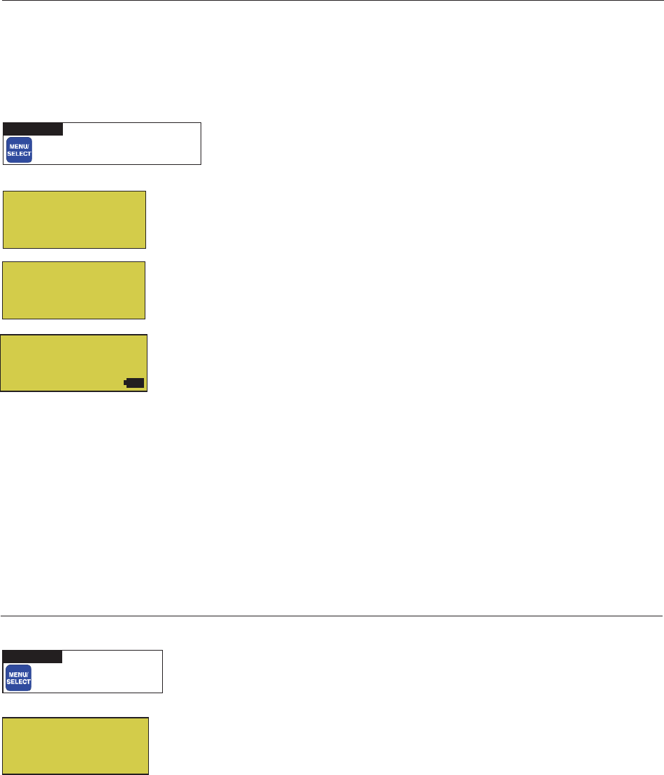
36
EasyTouch Wireless Control Panel User’s and Installation Guide
Settings Menu: Erase EEPROM (Erase System Memory)
EasyTouch system configuration data is stored and retained in “Flash” memory in an EEPROM located on the
outdoor control panel motherboard, indoor control panel and wireless control panel. The EasyTouch user
system configuration data can be erased to restore the factory defaults settings. System information
automatically downloads from programmed components to non-programmed components in case of accidental
memory loss and to ease board replacement. Any optional controllers (iS4, QuickTouch QT4 controller) that
were configured will need to be reconfigured.
Erase EEPROM
The following procedure describes how to erase the system memory from either the main EasyTouch outdoor
control panel or the EasyTouch wireless control panel.
CAUTION: This procedure will erase all system settings. Any optional controllers will need to be
reconfigured.
Up/Down button: Select Yes .
Right button: The message “Erase EEPROM Are You Sure? No” is displayed.
Up/Down button: Select Yes .
Right button: Press this button to erase system data and restore the factory
defaults. The display will go blank, then the main screen will be displayed.
▼ SETTINGS ▼ Erase EEPROM Erase EEPROM
Getting There
▲
Settings Menu: Backlight Options
Use the backlight “On Time” option to set the duration that the backlight is on. The “Brightness” setting allows
you to set the backlight brightness. These options can help to reduce power consumption and extend battery
life. The Backlight options are:
•On Time: Backlight is on for 60 seconds, 30 seconds, five minutes, or off. The default setting is 30
seconds.
•Brightness: Backlight brightness can be set to low, medium or high. The default setting is medium.
Backlight Options
To set the backlight duration and brightness:
Up/Down buttons: Select 30 S, 60 S or OFF for the backlight duration.
Right button: Select LOW, MED or HI for the backlight brightness setting.
Menu/Select: Press this button to save settings and to return to the previous screen
AUTO HEATER
SPA 95°F / 100°F
AIR 70°F
MON 09:30 AM
Erase EEPROM
Erase ALL? No (Yes)
T
S
T
S
Erase EEPROM
Are You Sure?
No (Yes)
▼ SETTINGS ▼ BACKLIGHT OPTIONS
Getting There
BACKLIGHT OPTIONS
On Time: 30 S
Brightness: MED T
S
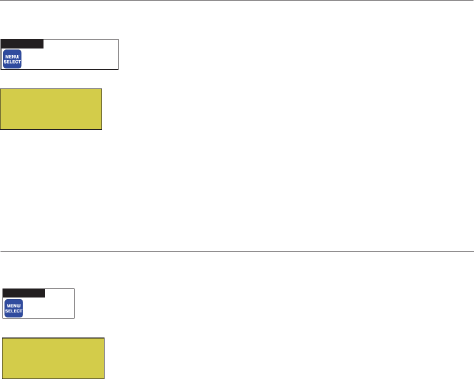
37
EasyTouch Wireless Control Panel User’s and Installation Guide
Settings Menu: Power Save Options
This option sets the time that the EasyTouch wireless control panel will shut down if there is no control panel
activity. Use the power save options to reduce power consumption and extend battery life. The options are:
•Pwrsave Options: Set the power save time to 30 seconds, 60 seconds, or five minutes before the
unit shuts down. The default time is 60 seconds.
Note: If the unit is not used for 60 (default) seconds the power save function switches off the unit. To
switch the unit on, press the “POWER” button. The unit can also be switched off manually using the
“Power Off” function, see page 41 for more information.
Idle Time
To set the idle time for the EasyTouch wireless control panel:
Right or Up/Down buttons: Select 30 S, 60 S or 5 M.
Menu/Select: Press this button to save settings and to return to the previous screen.
Spa Side [Off/On]
Enable or disable the iS4 Spa Side remote. This feature is useful for families with young children or when you
go on vacation. It allows you to switch off the iS4 Spa Side remote at the control panel so that the remote
cannot be used.
Spa Side
To enable or disable the iS4 Spa Side remote:
Right button:: Select On or Off to enable or disable the spa side remote.
Menu/Select: Press this button to save settings and to return to the Main screen.
▼ SPA SIDE [On/Off]
Getting There
T
Delay Cancel
Schedules
Settings
Spa Side [On ]
S
▼ SETTINGS ▼ POWER SAVE OPTIONS
Getting There
PWRSAVE OPTIONS
IDLE TIME: 60 S

38
EasyTouch Wireless Control Panel User’s and Installation Guide
Diagnostics Menu: Software Rev
Displays the current software revision for the EasyTouch main control panel and the wireless control panel.
UIC: Displays the current software revision level for the wireless or indoor control
panel.
UOC: Displays the current software revision level for the outdoor control panel.
Menu/Select: Press this button to return to the Settings menu options. Press the
button again to return to the main menu options or press again to return to the Main
screen.
Diagnostics Menu: Bootloader Rev
Displays the current bootloader revision for the wireless control panel and the EasyTouch outdoor control
panel.
UIC: Displays the current bootloader revision level for the wireless or indoor control
panel.
UOC: Displays the current bootloader revision level for the outdoor control panel.
Menu/Select: Press this button to return to the Settings menu options. Press the
button again to return to the main menu options or press again to return to the Main
screen.
Diagnostics Menu: Self Test
Tests the control panel LCD and buttons. Follow the on-screen prompts to perform the tests.
Note: If the Indoor Control Panel is connected to the EasyTouch outdoor control panel, select “LINK
CLOSED” in the UART test to abort the UART test. This allows the test to complete with PASSED.
Press the Right button to display the current software and bootloader revision levels
for the Indoor Control Panel.
Press the Right button to start the test:
Display Test: Press any button to start the LCD test.
Backlight Test: Press the Left then Right button.
Contrast Test III: Press any button to continue.
LED Test: Press any button to continue. All of the button LEDs will be tested.
Switch Test: Press any button to continue. As prompted, press the appropriate
buttons.
UART Test: Select “LINK CLOSED” to abort this test if the optional Indoor
Control Panel is connected to the EasyTouch load center.
Status: Passed - Code: None After you have completed the test an error code is
displayed. If the test was successful, “Passed” is displayed. For error code
descriptions, see “Self Test Error Codes,” on page 44.
Menu/Select: Press this button to return to the Settings menu options. Press the
button again to return to the main menu options or press again to return to the Main
screen.
▼ DIAGNOSTICS ▼ SOFTWARE REV
Getting There
▼ DIAGNOSTICS ▼ BOOTLOADER REV
Getting There
▼ DIAGNOSTICS ▼ SELF TEST
Getting There
Bootloader Rev
UIC: 1.000
UOC: 1.000
Software Rev
UIC: 1.000
UOC: 1.000
Backlight On
<=Backlight On
>=Backlight Off
Contrast: III
Press any button
LED Test
Switch Test
Press any button
UART Test
<=Link Closed
>=Link Open
Press Any Button
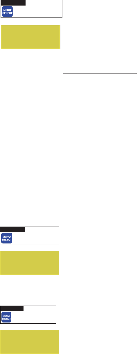
39
EasyTouch Wireless Control Panel User’s and Installation Guide
Diagnostics Menu: Chlorinator
Displays the current IntelliChlor chlorination system status. For more information, refer to the IntelliChlor
Electronic Chlorine Generator User’s Guide (P/N 520589).
Menu/Select: Press this button to return to the Settings menu options. Press the
button again to return to the main menu options or press again to return to the Main
screen.
SALT LEVEL: Displays the current salt level. Values from 0 to 12750 ppm in 50 ppm
increments.
IntelliChlor Status messages:
SUPER CHLORINATE: IntelliChlor is in “Super Chlorination mode (see page 25)
COM LINK ERROR: Check cable from IntelliChlor to EasyTouch motherboard.
Check FLOW/PCB: Check IntelliChlor electrolytic cell controller. Refer to IntelliChlor
User’s Guide troubleshooting information.
LOW SALT: Add salt to pool water. The water salt level is between 2500 ppm and
2900 ppm. The IntelliChlor will continue to produce chlorine at a reduced level.
VERY LOW SALT: Not enough salt in pool. The water salt level has fallen below 2500
parts per million (ppm). IntelliChlor will not produce chlorine until additional salt is
added manually.
HIGH CURRENT: Check IntelliChlor electrolytic cell controller. Refer to IntelliChlor
User’s Guide troubleshooting information..
CLEAN CELL!!: Cell has calcium build up and requires cleaning. Refer to IntelliChlor
User’s Guide for cleaning instructions.
LOW VOLTAGE: Check IntelliChlor electrolytic cell controller. Refer to IntelliChlor
User’s Guide troubleshooting information.
OK - NO ERRORS: IntelliChlor is in normal operating mode.
Diagnostics Menu: Water Temp
Displays the current water temperature for the pool and spa.
Menu/Select: Press this button to return to the Settings menu options. Press the
button again to return to the main menu options or press again to return to the Main
screen.
Diagnostics Menu: Solar Temp
Displays the current temperature.
Menu/Select: Press this button to return to the Settings menu options. Press the
button again to return to the main menu options or press again to return to the Main
screen.
▼ DIAGNOSTICS ▼ WATER TEMP
Getting There
▼ DIAGNOSTICS ▼ SOLAR TEMP
Getting There
▼ DIAGNOSTICS ▼ CHLORINATOR
Getting There
T
Chlorinator
Salt Level:3200ppm
Status:
[OK-NO ERRORS]
S
T
Water Temperature
75° F
S
T
S
Solar Temperature
85° F
40
EasyTouch Wireless Control Panel User’s and Installation Guide
Diagnostics Menu: Air Temp
Displays the current outside air temperature.
Menu/Select: Press this button to return to the Settings menu options. Press the
button again to return to the main menu options or press again to return to the Main
screen.
Diagnostics Menu: Disp Codes
Perform a communications test with installed equipment. Use this feature when testing the system.
To start test:
Down button: Select Ye s to enable the feature.
Menu/Select or Right button: Press either of these buttons to start
communications test. Digits display on the right side of all menu screens indicating
verification transmit and received packets.
To stop test: Go to the “Disp Op Codes” menu and select No, then press the
Menu/Select button to exit.
Diagnostics Menu: Cir Names: [Off/On]
This feature is useful if you have renamed many circuits and want to view the original factory default circuit
names.
To enable:
Right button: Select On to view the factory default circuit names.
Menu/Select: Press this button to exit.
To disable:
Right button: Select Off to disable the feature.
Menu/Select: Press this button to exit.
Diagnostics Menu: Reset System
Reset the EasyTouch wireless control panel. Resetting the wireless control panel will not effect the stored
system configuration settings.
Right button: Press the Right button to reset system. The main screen will be
displayed and communication will be established with the EasyTouch outdoor control
panel at the pool equipment pad.
▼ DIAGNOSTICS ▼ AIR TEMP
Getting There
T
Air Temperature
72° F
S
T
Disp Op Codes
Display? No
S
T
Solar Temp
Air Temp
Disp codes
Cir Names [Off]
S
X
▼ DIAGNOSTICS ▼ CIR NAMES
Getting There
[Off]
▼ DIAGNOSTICS ▼ DISP CODES
Getting There
T
S
X
Air Temp
Disp codes
Cir Names [Off]
Reset System
▼ DIAGNOSTICS ▼ RESET SYSTEM
Getting There
41
EasyTouch Wireless Control Panel User’s and Installation Guide
Diagnostics Menu: Flash Update
Use this feature to update the EasyTouch wireless control panel firmware. The unit must be connected to a
PC in order to update the firmware.
Press MENU/SELECT to exit the flash mode.
Power OFF
The “Power Off” function switches off battery power to the EasyTouch wireless control panel. Use this
function to manually switch off the unit. To switch the unit on, press the Power ON button.
Right button: Press the Right button to switch off the unit.
▼ DIAGNOSTICS ▼ FLASH UPDATE
Getting There
▼ POWER OFF [PRESS TO SWITCH OFF]
Getting There
▼
42
EasyTouch Wireless Control Panel User’s and Installation Guide
Blank Page

43
EasyTouch Wireless Control Panel User’s and Installation Guide
Section 3
Troubleshooting
Troubleshooting
Use the following troubleshooting information to help resolve problems that may occur when using the
EasyTouch system. If by following the recommended actions you are still unable to resolve the problems,
please contact Technical Support (see page vi).
Frequently Asked Questions (FAQ)
How do I setup a two-speed pump?
A two-speed pump operates using two relays and one or more circuits. The first relay turns the pump on or
off. Assuming this is a filter pump, this circuit is controlled by the pool and spa circuits or any other circuit that
may be tied to the filter pump (such as circuits with freeze protection, etc.). The second relay switches the
pump from low speed to high speed. The default condition is low speed. Up to seven circuits (EasyTouch 8),
three circuits (EasyTouch 4) may be assigned to trigger the pump to high speed. Note: These circuits do not
switch the pump on.
To configure a two-speed pump relay, refer to “Settings Menu: 2-Speed Pump,” on page 31. The 2-Speed
pump relay connector is plugged into the 2-SPD output on the EasyTouch motherboard.
Can I switch the heater on and change the temperature from the spa?
The heater may be switched on from the spa location using the iS4 Spa-Side remote or by the QuickTouch
wireless remote controller. To learn more about these remotes and controllers, see page 6. However, the iS4
and QuickTouch wireless remote controller cannot adjust the water temperature.
How do I switch on solar heating?
The system must first be configured for solar heating. Go to the “Heat” menu (see page 18) and enable
“Solar” as the heat source (Settings Menu: Heat > Solar). Note: Do not set solar as a heat pump. Then the
heating method must be selected for each body of water.
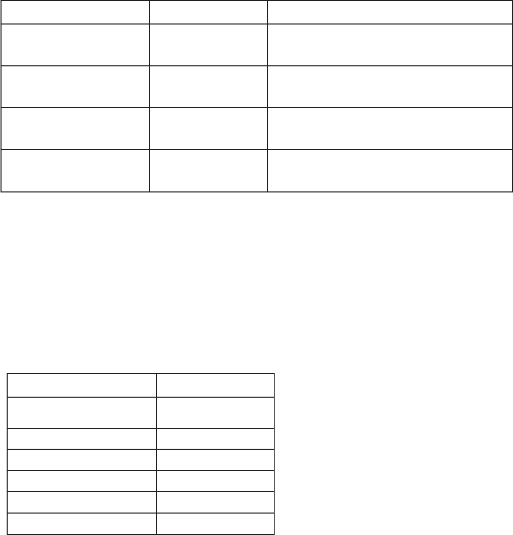
44
EasyTouch Wireless Control Panel User’s and Installation Guide
egasseMrorrEesuaCelbissoPnoituloS
niaMehtnosyalpsiD(rrEriA
)neercS
detcennoctonrosnesriA
hcuoTysaEehtot
.dra
obrehtom
12JotdetcennocsigulprosnesriaehttahtkcehC
rosnesehttahtkcehC.draobrehtomehtnorotcennoc
.ylreporpdetcennocsieriw
nisyalpsiD(rrEerutarepmeTriA
)unem"scitsongaiD"eht
detcennoctonrosnesriA
hcuoTysaEehtot
.
draobrehtom
12JotdetcennocsigulprosnesriaehttahtkcehC
.draobrehtomehtnorotcennoc
syalpsiD(rrEerutarepmeT
retaW
)unem"scitsongaiD"ehtni
tonrosnesretaW
ehtotdetcennoc
.draobrehtomhcuoTysaE
12JotdetcennocsigulprosnesretawehttahtkcehC
.draobrehtomehtnorotcennoc
syalpsiD(rrEerutarepmeTraloS
)unem"scitsongaiD"ehtni
tonro
snesraloS
ehtotdetcennoc
.draobrehtomhcuoTysaE
12JotdetcennocsigulprosnesralosehttahtkcehC
.draobrehtomeh
tnorotcennoc
edoCrorrEnoitpircseD
0edoClenaplortnocehT-SSAP
smelborponsah
1edoCthgilkcabDCL
2edoCtsartnocDCL
3edoCsDEL
4edoC)s
nottub(hctiwS
5edoCtsetkcabpoolTRAU
EasyTouch Error Messages
Error Messages
If the system detects that a sensor is not connected to the EasyTouch load center or it is defective, an error
message is displayed in the “Diagnostics” menu. The following lists the sensor errors.
Self Test Error Codes
The “Self Test” feature is intended for use by service personnel. If after performing a control panel self test
(see page 38) there were no errors detected, Code 0 is displayed, indicating that there were no problems and
the test was successful. If a problem is detected during the test, an error code is displayed upon completion of
the test. For example Code 3 would indicate a problem with the LEDs on the control panel. If multiple errors
are detected, multiple code numbers are displayed. For example, Codes 4, 2, 1, would indicate problems
detected with the buttons, LEDs, and the LCD backlight on the control panel.
The following lists the control panel self test error codes.
Error Code Table

45
EasyTouch Wireless Control Panel User’s and Installation Guide
egasseMsutatSesuaCelbissoPnoituloS
SRORREON-KOlamronrolhCilletnI
.edomgnitarepo
A/N
ETANIROLHCREPUSrepuS"nisi
rolhCilletnI
42rofedom"noitanirolhC
.sruoh
52egapees(edomnoitanirolhCrepuS“nisirolhCilletnI
)sliatedrof
RO
RREKNILMOCnoitacinummocrolhCilletnI
hcuoTysaEhtiwrorre
.draobrehtom
.draobrehtomhcuoTysaEotrolhCilletnImorfelbackcehC
BCP/WOLFKCEHCrolhCilletnIkcehC
.lleccitylortcele
gnitoohselbuortediuGs’resUrolhCilletnIotref
eR
.noitamrofni
TLASWOL.retawloopottlasddA .mpp0092dnampp0052neewtebsileveltlasretawehT
ataenirolhcecudorp
oteunitnoclliwrolhCilletnIehT
.sliatedrofediuGs'resUrolhCilletnIeeS.leveldecuder
TLASWOLYREV.loopnitlash
guonetoN repstrap0052wolebnellafsahleveltlasretawehT
litnuenirolhcecudorptonlliwrolhCilletnI.)mpp(noill
im
s'resUrolhCilletnIeeS.yllaunamdeddasitlaslanoitidda
.sliatedrofediuG
TNERRUCHGIHrolhCilletnIkcehC
.llec
citylortcele
otrefeR.rellortnoclleccitylortcelerolhCilletnIkcehC
.noitamrofnignitoohselbuortediuGs’resUrolhCilletnI
!!LLECNAELCpudliubmuiclacsahlleC
.gninaelcseriuqerdna
otrefeR.gninaelcseriuqerdnapudliubmuic
lacsahlleC
.snoitcurtsnigninaelcrofediuGs’resUrolhCilletnI
EGATLOVWOLrolhCilletnIkcehC
.lleccitylortcele
g
nitoohselbuortediuGs’resUrolhCilletnIotrefeR
.noitamrofni
Maximum Programs Exceeded
The “Maximum Programs Exceeded” message displays in the “Schedules” menu if you try to create a new
program after exceeding the 12 program limit. To create a new program you must first delete an existing
program. For information about deleting a program, refer to “Schedule Menu” on page 20.
IntelliChlor Error Messages
IntelliChlor status and error messages are displayed in the “Chlorinator” menu (see page 39). Use the
following information to resolve IntelliChlor system problems. To access the IntelliChlor menu, press
Menu > Diagnostics > Chlorinator.

46
EasyTouch Wireless Control Panel User’s and Installation Guide
Problem: iS4 fails to operate.
motpmySesuaCelbissoPnoituloS
.tnempiuqeetarepootsliaf4Si.delbasidsi4Si.4Siehtelbaneot73egapeeS
gniriWevitce
feD ehtsahnoitseuqni4SiehterusnE.putes4SiyfireV
otdengissatonsidna,stnemngissatiucricdetcepxe
.stiucricdesunu
ronoitarugifnoctcerrocnI
.putesnottub
.snottub4Siehtputesot33egapeeS
4SievitcefeD4SievitcefedecalpeR
foemosylnoetarepootsliaf4Si
.enifkrowsrehtotub,sehctiwseht
roenonogniriwevitcefeD
sdael4Sierom
.4SidnadraobrehtomnogniriwyfireV
ronoitarugifnoctcerrocnI
hctiwsottiucric
.tnemngissa
.noitcennocdraobrehtomyfireV
System Problem Diagnosis
Use the following information to resolve system problems.
Problem: The system works in Service Mode, but wireless control panel fails to operate.
motpmySesuaCelbissoPnoituloS
onsahlenaPlortnoCroodnI
,sDELon,knalb,neercs(-rewop
.)gnikrowtonsnottub
morfnu
rgniriwdaB
lortnoCroodtuO
ehtnidraobrehtom/lenaP
.retneCdaoL
nI.nekorberasnoitcennoconerusnednaelbacyfireV
ehT.noitalusniehtrednunekorbsieriwasesacemos
tcepsuseraelbacrotcudnocruofehtfoseriwretnecowt
)wolleYdn
aneerG(
tub,pusthgillenaPlortnoCroodnI
tinuehT.yltcerrocetarepootsliaf
ro,ffo/notnempiuqenruttonlliw
tont
ub,nosmetiemosnrutyam
raensDELtonyamdnaffo
.lenaplortnocnosnottub
gniriw/elbaCevitcefeDyfireVelbacnI.nekorb
erasnoitcennoconerusnedna
ehT.noitalusniehtrednunekorbsieriwasesacemos
tcepsuseraelbacrotcudnocruofehtf
oseriwretnecowt
)wolleYdnaneerG(

47
EasyTouch Wireless Control Panel User’s and Installation Guide
Problem: The Quick Touch remote will not work, or will not work dependably.
motpmySesuaCelbissoPnoituloS
nothgiltonseodDELREWOP
ehtnidetacoldraobrevieceReht
.llehsmalccitsalp
retneCdaoLhcuoTysaE
rewopevahtonseod
rewopehttahtdnadeilppusgniebsirewoperusnE
dellatsnireviecerehttuohtiwyltcer
rocsetareporetnec
roelbacevitcefeD
daoLehtotnoitcennoc
retneC
elbacdoognwonkgnisudraobehtfonoitcnufehtyfi
reV
gniriwllakcehC.tes
draobrevieceRevitcefeDtroppuSlacinhceTtcatnoC
thgiltonseodDELKNILMMOC
DELnoitarepol
amronnI.knilbro
sdnoces2yrevetsaeltaknilblliw
roelbacevitcefeD
daoLehtotnoitcennoc
retneC
elbacdoognwonkgn
isudraobehtfonoitcnufehtyfireV
tes
draobreviecerevitcefeDdraobreviecerecalpeR
yltcerrocnierasehctiwssserd
dA
derugifnoc
sserddaehttahtyfireV
ehtnosehctiws
dlehdnahdnarettimsnart
tcerroceradraobreviecer
hctamdna
deliafsahyrettabrettimsnarT
rettimsnarTecalpeR
yrettab
revieceRrorettimsnarTevitcefeD
emostub,snoitcnuftinU
r
o,krowtonodstiucric
tcerrocniehtetarepo
tiucric
tcerrocnisinoitarugifnochcuoTkciuQ
stiucricemostub,snoitc
nuftinU
ehtetareporo,krowtonod
tiucrictcerrocni
noitarugifnochcuoTkciuQ
tcerrocnisi
snottubputesot43egapeeS
taylbadnepedetarepootsliafro,etarepootsliaftinU
egnar
otsliafro,etarepootsliaftinU
egnartaylbadnepedeta
repo
esionlacirtceleevissecxE lacirtcele""ysion""morfyawareviecerehtetacoleR
srotomrewolbsahcustnempiuqe
snoitcurtsboynamooT
rettimsnartehtneewteb
reviecerdna
dnalatemdnuorgmorfyawareviecerehtetacoleR
snoitcurt
sbo
raenootsitinurevieceR
dnuorgeht
neewtebecnatsidehtezimixamotreviecerehtetacoleR
dnuorgehtdnaannetnare
viecereht

48
EasyTouch Wireless Control Panel User’s and Installation Guide
motpmySesuaCelbissoPnoituloS
fforononrutotsmeestinU
/resuehttuohtiwstiucric
rettimsnart
siemohybraenA
ralimi
sagnitarepo
tinusseleriw
dnarettimsnartehtrofedocsserddaetanretlanatceleS
dnareviecerhtobnosehctiwsehtegnahC.reviecer
.gnittesgnihctamtub,etanretlanaotetomer
tnempiuqesnrutylbadnepedtinU
sitnempiuqeecnotub,NO
ylbadnepedtonseodtigninnur
siegnarro,FFOtnempiuqenrut
tnempiuqenehwdecuderyltaerg
gninnursi
siesionlacirt
celeeudnU
roenoybdecudorpgnieb
tnempiuqefoseceiperom
ehtotytimixorpesolcni
.reviecer
sahcustnempiuqemorfyawarevieceRehtetacoleR
tahtnoitacolanirevieceRehtetacoleRsrotomrewolb
resuehtaeraehtotsnoitcurtsborewefs
edivorp
.rettimsnartehtsetarepoylnommoc
yltaergsahtub,setarepotinU
roirpotderapmocegnardecuder
noitcnuf
si
yrettabrettimsnarT
.gniliaf
.)V32302epyt(yrettabrettimsnarTecalpeR
Problem: The Quick Touch remote will not work, or will not work dependably (Continued).

49
EasyTouch Wireless Control Panel User’s and Installation Guide
Section 4
EasyTouch Transceiver Module Installation
Installing the EasyTouch Transceiver Module
Use the following procedure to install the EasyTouch transceiver module near the EasyTouch load center and
the transceiver cable to the EasyTouch motherboard COM port. Read through the installation procedure
before starting.
EasyTouch wireless control panel kit
The EasyTouch wireless control panel kit consists of:
• EasyTouch wireless control panel
• Two AA-size alkaline batteries
• Transceiver module
• Four plastic anchors and retaining screws (to mount the transceiver module)
Mounting the EasyTouch Transceiver Module
The Transceiver module is a two-way radio device with an attached antenna that communicates to and from
the EasyTouch system via the wireless hand-held wireless control panel. Mount the Transceiver module at a
convenience location (on a flat vertical surface) near the Load Center, at a minimum of 5 ft. above ground
level to optimize the functional operating range of the wireless control panel.
CAUTION - To avoid signal interference, mount the Transceiver module antenna a minimum of
10 ft. away from the Load Center, any metal surface/structure, or air blower located in the immediate area of
the equipment pad.
To mount the EasyTouch transceiver module:
1. CAUTION - Switch the main power off at the EasyTouch load center.
2. Remove the two retaining screws securing the transceiver case to the back plate. Carefully slide the
case off the back plate.
3. CAUTION -Electrostatic Discharge (ESD): Hold the circuit board from the edges. Do not
touch the board components, electrostatic discharge can damage the board. Slide the
transceiver circuit board up and out of the back plate.
4. Position the back plate against the mounting surface so that the case is oriented in an upright position
(with the antenna pointing upwards). Use a pencil to mark the four mounting points. Drill four 3/16 in.
diameter holes into the mounting surface. If screws are not being used, insert the four plastic wall
anchors (provided in the kit).
5. Feed a UL approved four 22 AWG conductor cable through the knockout hole at the bottom of the
enclosure. Do not run wire through the drain holes. If the knockout hole is not being used to run wire
through, drill a hole through the bottom of the back plate, route the wire through the hole and seal it
using a fitting with a few feet of conduit or some other sealant between the case and the cable.
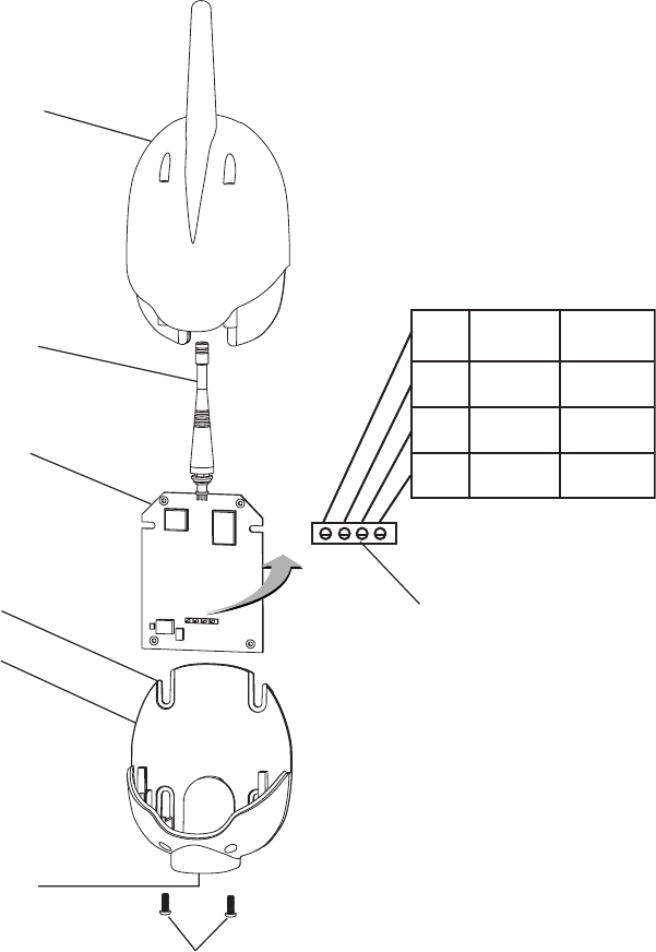
50
EasyTouch Wireless Control Panel User’s and Installation Guide
6. Position the back plate over the mounting points and secure it with the four mounting screws
(provided in the kit).
7. Carefully slide the transceiver circuit board into the back plate.
8. Strip the leads of the communication cable wires back ¼ in. Insert the wires into the connector screw
terminals (provided in the kit). Using a small flat-blade screwdriver, secure the wires with the
terminal screws. Make sure to match the color-coding of the wires: GND = Black, Green = -DT,
Yellow = +DT, and Red = +15. Connect the screw terminal connector onto the transceiver circuit
board.
9. Slide the case over the back plate. Secure the case to the back plate using the two retaining screws.
10. Proceed with “Connecting the EasyTouch Transceiver EasyTouch Load Center,” on page 51.
Transceiver Module
Screw terminals
Back plate
Retaining screws
Transceiver Circuit Board
Case
Knockout hole
Antenna
Mounting point (4x)
1DNGKLB
2TD-NRG
3TD+LEY
4V51DER
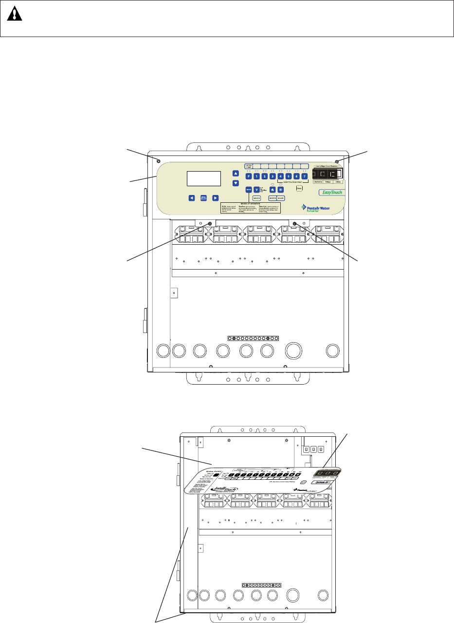
51
EasyTouch Wireless Control Panel User’s and Installation Guide
Connecting the EasyTouch Transceiver to the EasyTouch Load Center
WARNING - Switch OFF the main system power to the EasyTouch load center before making any
connections.
1. Unlatch the two enclosure door spring latches, and open the door.
2. Remove the two retaining screws securing the high voltage cover-panel, and remove it from the
enclosure.
3. Loosen the two access screws securing the control panel.
4. Lower down the hinged control panel to access the EasyTouch motherboard.
Panel retaining screw
(Cover-panel not
shown)
Access
screw
Retaining
screw
Access
screw
Control panel
Raceway
Control panel
Personality
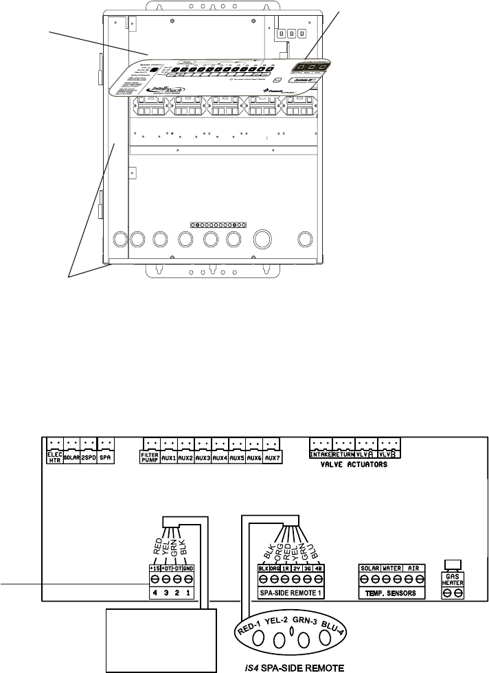
52
EasyTouch Wireless Control Panel User’s and Installation Guide
COM PORT
(J20)
Indoor Control Panel
IntelliChlor
IntelliFlo
RF Transceiver
EasyTouch Motherboard
2. At the EasyTouch load center, route the four conductor transceiver connection cable into the lower
plastic grommet, up through the low voltage raceway to the motherboard.
3. Strip back the cable conductors ¼ inch. Insert the wires into the screw terminals (provided in the
Personality Kit). Secure the wires with the screws. Make sure to match the color-coding of the
wires: GND = Black, Green = -DT, Yellow = +DT, and Red = +15
4. Insert the screw terminal connector onto the COM-PORT (J20) connector on the motherboard.
Note: Multiple wires may be inserted into a single screw terminal.
5. After the connection has been completed, close the control panel into its original position and secure
it with the two access screws.
6. Install the front panel and secure it with the two retaining screws.
7. Close the EasyTouch load center front door. Fasten the two spring latches.
8. Switch the power on to the EasyTouch load center.
Raceway
Control panel
Motherboard
53
EasyTouch Wireless Control Panel User’s and Installation Guide
Glossary
High Voltage Compartment: Large lower right compartment of Load Center for all high voltage wiring
including circuit breakers, relays, and GFCI.
Indoor Control Panel: Optional nine or 14 button remote controller with LCD (liquid crystal display) wired to
the EasyTouch motherboard in the load center. The control panel can be wall mounted inside the house to
control the EasyTouch system.
iS4: Optional four function Spa-Side remote. Can be spa wall or deck mounted.
Load Center: Metal enclosure with power relays, transformer, and circuit breakers. Used for distributing
power for controlling the EasyTouch system. Also known as the “sub-panel.”
Low Voltage Compartment: Top compartment of EasyTouch load center for all low voltage wiring.
Low Voltage Raceway: Vertical space in the left side of EasyTouch load center for low voltage cabling.
Control Panel: Control panel with flexible hinge installed in upper portion of EasyTouch Load Center to
control the EasyTouch system.
Motherboard: The circuit board mounted on top of the EasyTouch control panel.
Receiver/Antenna: Used with the QuickTouch (QT4) to receive radio frequency (wireless) transmissions.
Relay Circuits: The circuits that control the relay outputs on the EasyTouch motherboard. Connectors are
located on the top edge of the circuit board.
Screw Terminal Connector: Removable connector that may attach to circuit board with multiple sockets
(anywhere from 2 to 12) to receive wires from controllers and sensors; wires held by screw terminals; multiple
wires of a small enough gauge (usually 22 AWG) may be coupled to a single socket of a terminal connector.
54
EasyTouch Wireless Control Panel User’s and Installation Guide
Notes

P/N 520688 - Rev X1 - September 26 2005 - Preliminary Issue