Pepperl Fuchs IUH-F117-V1 UHF RFID Reader User Manual
Pepperl + Fuchs Inc UHF RFID Reader
UserManual.wiki
>
Pepperl Fuchs
>
IUH F117 V1 User Manual
user manual
Navigation menu
Upload a User Manual
Namespaces
Wiki Guide
HTML
PDF
Info
Views
User Manual
Discussion / Help
Navigation

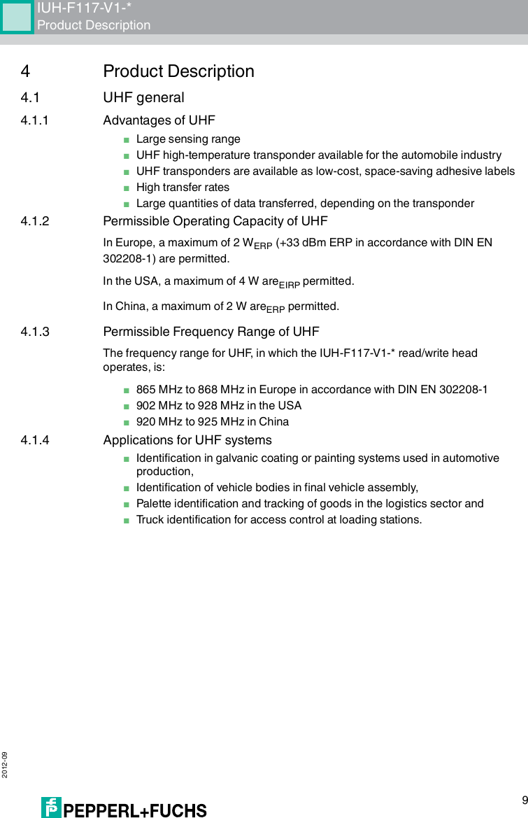
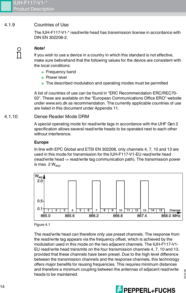
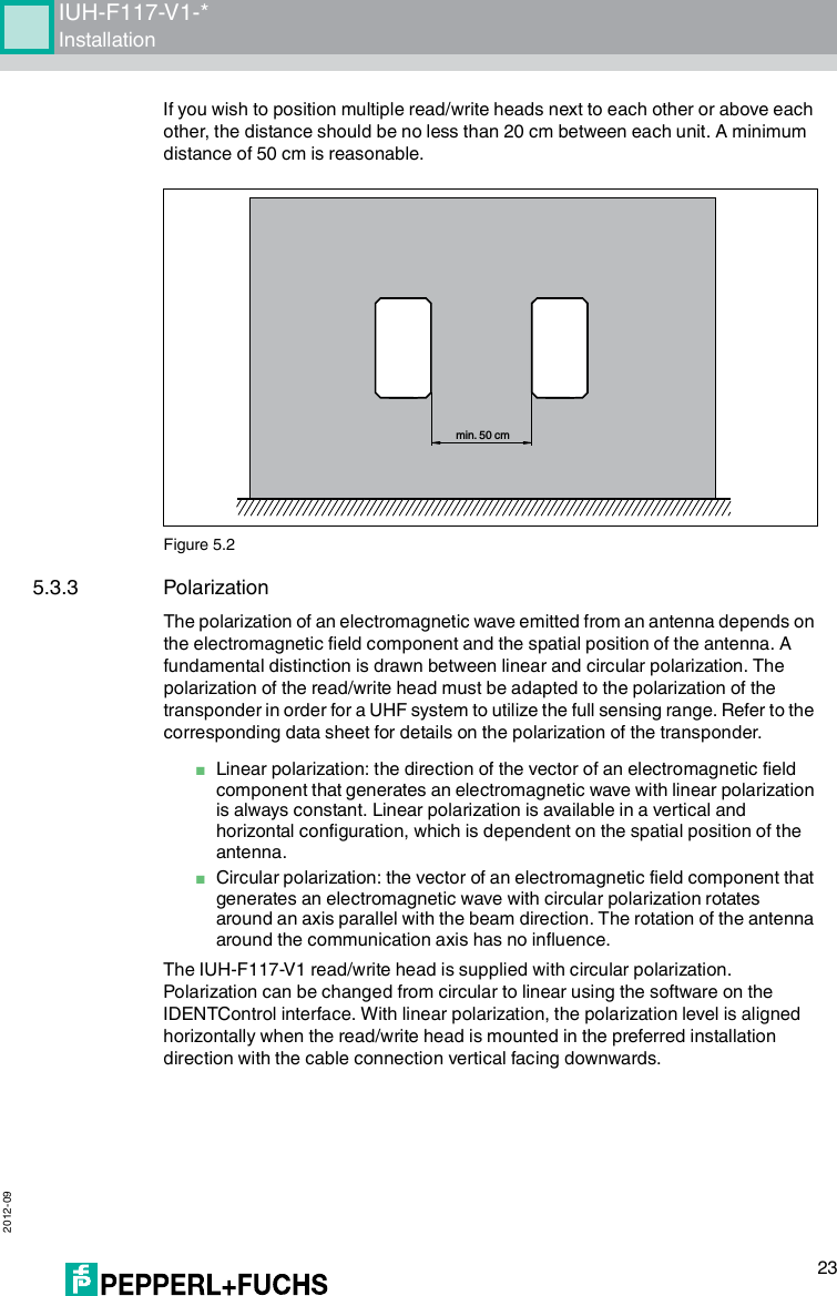
![2012-0910IUH-F117-V1-*Product Description4.1.5 Memory Structure of a Tag in Accordance with ISO 18000-6C/EPC Class 1 Gen 2The memory module of an EPC-type Class 1 Gen 2 tag is split into 4 segments. The essential contents of these segments are:Segment Function LengthBank 00 Password manager Depending on the tag type, see table "Tag Types UHF 868 MHz" on page 35"Special read-only code" columnBank 01 Unique Item Identifier (UII)Electronic Product Code (EPC)Depending on the tag type, see table "Tag Types UHF 868 MHz" on page 35"Special read-only code" columnBank 10 Ta g I D (T ID ) 8 byteBank 11 User data Depending on the tag type, see table "Tag Types UHF 868 MHz" on page 35"Special read-only code" columnUSERTIDUII/EPCRESERVEDRFU [7:0]10h1Fh...MSB LSBDSFID [7:0]00h0FhTID [15:0]10h1Fh...MSB LSBTID [31:16]00h0FhUII/EPC [N:N-15]20h210h2Fh...MSB LSBPC [15:0]10h1FhUII/EPC [15:0]CRC-16 [15:0]00h0FhAccess Password [15:0]30h3Fh...MSB LSBAccess Password [31:16]20h2FhKill Password [15:0]10h1FhKill Password [31:16]00h0FhBank 11Bank 10Bank 01Bank 00SR/ERSW/EWSS/ESSP/EPSF/EF...Optional XPC_W2 [15:0]Optional XPC_W2 [15:0]...220h21Fh22FhMemory moduleCommandsIUH-F117-V1-*](https://usermanual.wiki/Pepperl-Fuchs/IUH-F117-V1/User-Guide-1812944-Page-10.png)
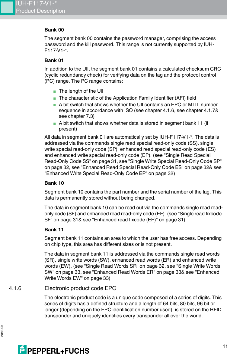
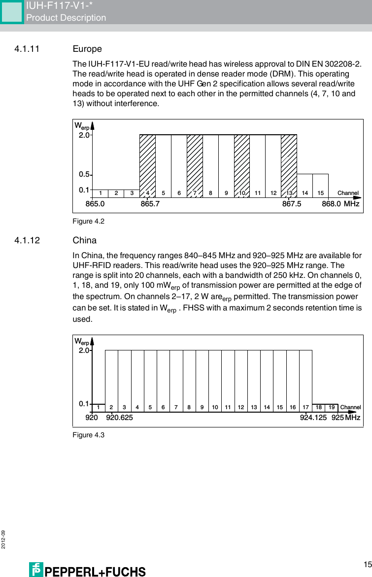
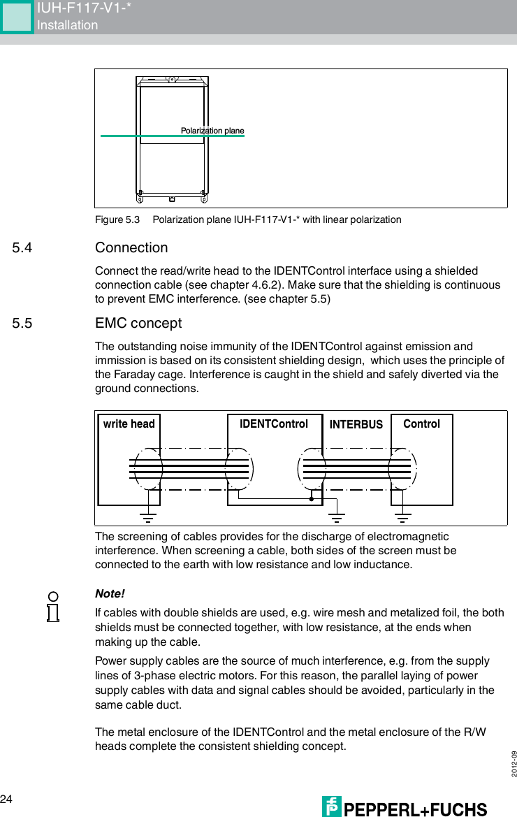
![2012-0916IUH-F117-V1-*Product Description4.1.13 USAThe ISM band from 902 to 928 MHz is available in the USA. The band is split into 50 channels, each with a 500 kHz bandwidth. FHSS with a maximum retention time of 4 seconds is employed. All channels must be used. Channel restriction is not permitted.In contrast to the read/write heads for Europe and China, the transmission power is stated in Weirp .Figure 4.44.1.14 RFID Frequency Bands■100–135 kHz: Low frequency LF■13.56 MHz: High frequency HF■865–868 MHz (Europe), 902–928 MHz (USA), 920–925 MHz (China): ultra-high frequency UHF■2.45 GHz and 5.8 GHz: Microwave MW4.1.15 Relevant UHF standardsEuropean radio standards: EN 300220 and EN 302208Application recommendations for RFID labels, information on recyclability, installation of readers and antennas: ISO/IEC TR 24729 parts 1-4Installation and commissioning of UHF RFID systems: ETSI TR 102436Radio interface description "UHF Gen2", "Electronic Product Code" (EPC): ISO/IEC 18000-6, Annex 1 in part C0.24.0902.75 927.25MHzChannelWeirp10 15 2051 30354025 45 50Frequency[MhZ]125 kHz2,45 GHz13,56 MHz5,8 GHz868/915 MHz0,1LF110HF100 1000UHF10000MW](https://usermanual.wiki/Pepperl-Fuchs/IUH-F117-V1/User-Guide-1812944-Page-16.png)
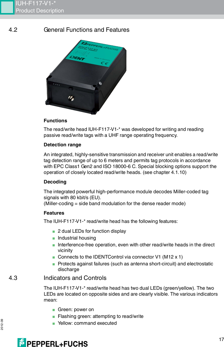
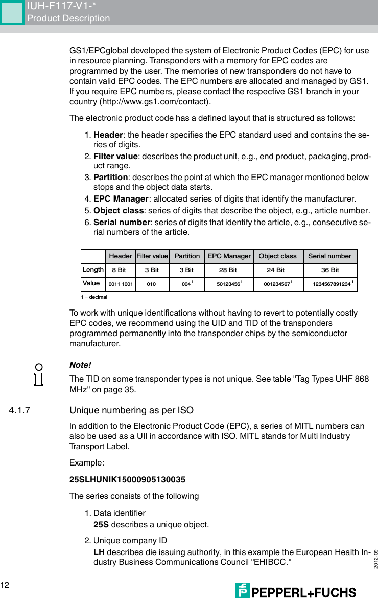
![IUH-F117-V1-*Operation 2012-0935Ta g Ty pe s U HF 8 68 M H z7.3.2 ReadParam/WriteParam CommandsThe configuration commands enable you to set or read the following parameters via the WriteParam WP and ReadParam RD commands:■Linear/circular antenna polarization, type=AP (AntennaPolarisation)■Transmission power, type=PT (PowerTransmit)■Permitted channels in the Dense Reader Mode, type=CD (ChannelDRM)■Complete reset of all parameters to the default condition, type=RD (Reset to Default)■Anti-collision algorithm on/off, type=AC (AntiCollision)■Permitted number of read/write attempts in the event of an error, type=TA (TriesAllowed)■Number of unsuccessful read attempts up to Status 5, type=E5 (EnhancedStatus5)■Specified bank on which the write and read commands SR, ER and SW are accessed, type=MB (Memory Bank)The parameters are generally saved in the read/write head IUH-F117-V1-* as non-volatile.Ta g type Chip type DetailsP+F desig-nation TIDData [bytes]Bank 00 [bit]Special read-only code [bit]Unique read-only code72 EPC Class 1 Ge n 2NXP UCode-EPC-G2XMIUC72 E2006003 + serial number64 32 + 32 240 Ye s73 EPC Class 1 Ge n 2Alien Higgs-2 IUC73 E2003411-32 + 32 96 No74 EPC Class 1 Ge n 2NXP UCode-EPC-G2IUC74 E2006001 + serial number28 32 + 32 96 Ye s75 EPC Class 1 Ge n 2Impinj Monza 2.0IUC75 E2001071-32 + 32 96 No76 EPC Class 1 Ge n 2Alien Higgs-3 IUC76 E2003412 + serial number64 32 + 32 240 Ye s80 EPC Class 1 Ge n 2- - Serial number- - Max. 96 -Table 7.1 Tag types 868 MHz](https://usermanual.wiki/Pepperl-Fuchs/IUH-F117-V1/User-Guide-1812944-Page-35.png)
![2012-0936IUH-F117-V1-*OperationRead ParamThis command reads configuration parameters from the IQH2-... and IUH-F117-V1-* read/write head.SyntaxWrite ParamThis command writes configuration parameters to the IQH2-... and IUH-F117-V1-* read/write head.SyntaxFor additional details on the parameters see chapter 7.3.3.7.3.3 ParamTypStored Configuration SCThis parameter reads out the entire parameterization of the IUH-F117-V1-* read/write head.Example:RP1USC.00.00 reads out the entire parameterization in the following sequence:Command: RP <ChanNo> <SystemCode> <ParamTyp> <ParamLength> <CHCK> <ETX>Response: <Status> <Data> <CHCK> <ETX>RP <SystemCode><ParamTyp> <ParamLength>Command: WP <ChanNo> <SystemCode> <ParamTyp> <ParamLength> <Data> <CHCK> <ETX>Response: <Status> <CHCK> <ETX>WP <SystemCode><ParamTyp><ParamLength><Value>ParamTyp: SCByte position Meaning Value range[0] [1] Device detection IUH-F117-V1-* = .7D.68IUH-F117-V1 = .7B.51[2] Default flag Default = .64Modified = .6D[3] [4] PT parameter from 100 mW = .00.64to 2000 mW = .07.D0[5] CD parameter Number of set channels = 1–4[6]–[9] Set channels see "Channel DRM CD (IUH-F117-V1-EU Only)" on page 38](https://usermanual.wiki/Pepperl-Fuchs/IUH-F117-V1/User-Guide-1812944-Page-36.png)
![IUH-F117-V1-*Operation 2012-0937Antenna Polarization APThis parameter switches polarization to linear/circular or reads out the currently set polarization.Example: WP1UAP.00.01L switches the polarization to linear WP1UAP.00.01C switches the polarization to circular RP1UAP.00.00 reads out the set polarizationSet the polarization according to the read/write tag used (see chapter 5.3.3). Higher sensitivity if both the read/write head and the read/write tag are polarized linearly. There are gaps in the detection range if the read/write head is polarized linearly.Power Transmit PTThis parameter sets the transmission power in mW or reads out the set transmission power.The transmission power is stated for IUH-F117-V1-EU and IUH-F117-V1-CN in Werp . The transmission power is stated in W for the read/write head IUH-F117-V1-USeirp .Example: WP1UPT.00.02.00.64 sets 100 mWerpWP1UPT.00.02.07.D0 sets 2000 mWerpRP1UPT.00.00 reads out the set transmission power[10] TA parameter See "Tries Allowed TA" on page 39[11] E5 parameter See "Enhanced Status 5 E5" on page 39[12] AP parameter See "Antenna Polarization AP" on page 37[13] AC parameter See "Anti-Collision AC" on page 38[14] QV parameter See "Q-Value QV" on page 39[15] MB parameter See "Memory Bank MB" on page 40ParamTyp: APDefault AP = CValue range: L, CParamTyp: PTDefault: PT = .07.D0bin = 2000 mWerpValue range: 100–2000 mWerp100–4000 mWeirpByte position Meaning Value range](https://usermanual.wiki/Pepperl-Fuchs/IUH-F117-V1/User-Guide-1812944-Page-37.png)

![2012-0944IUH-F117-V1-*ASCII table10 ASCII tablehex dec ASCII hex dec ASCII hex dec ASCII hex dec ASCII00 0NUL 20 32 Space 40 64 @60 96 '01 1SOH 21 33 !41 65 A61 97 a02 2STX 22 34 "42 66 B62 98 b03 3ETX 23 35 #43 67 C63 99 c04 4EOT 24 36 $44 68 D64 100 d05 5ENQ 25 37 %45 69 E65 101 e06 6ACK 26 38 &46 70 F66 102 f07 7BEL 27 39 '47 71 G67 103 g08 8BS 28 40 (48 72 H68 104 h09 9HT 29 41 )49 73 I69 105 I0A 10 LF 2A 42 *4A 74 J6A 106 j0B 11 VT 2B 43 +4B 75 K6B 107 k0C 12 FF 2C 44 ,4C 76 L6C 108 l0D 13 CR 2D 45 -4D 77 M6D 109 m0E 14 SO 2E 46 .4E 78 N6E 110 n0F 15 SI 2F 47 /4F 79 O6F 111 o10 16 DLE 30 48 050 80 P70 112 p11 17 DC1 31 49 151 81 Q71 113 q12 18 DC2 32 50 252 82 R72 114 r13 19 DC3 33 51 353 83 S73 115 s14 20 DC4 34 52 454 84 T74 116 t15 21 NAK 35 53 555 85 U75 117 u16 22 SYN 36 54 656 86 V76 118 v17 23 ETB 37 55 757 87 W77 119 w18 24 CAN 38 56 858 88 X78 120 x19 25 EM 39 57 959 89 Y79 121 y1A 26 SUB 3A 58 :5A 90 Z7A 122 z1B 27 ESC 3B 59 ;5B 91 [7B 123 {1C 28 FS 3C 60 <5C 92 \7C 124 |1D 29 GS 3D 61 =5D 93 ]7D 125 }1E 30 RS 3E 62 >5E 94 ^7E 126 ~1F 31 US 3F 63 ?5F 95 _7F 127 DEL](https://usermanual.wiki/Pepperl-Fuchs/IUH-F117-V1/User-Guide-1812944-Page-44.png)
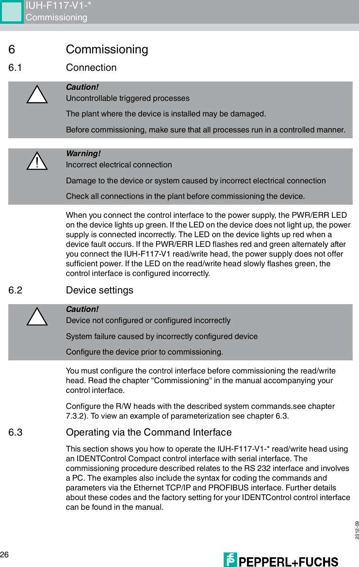
![IUH-F117-V1-*Appendix 2012-0947Figure 11.1 Horizontal detection range with horizontal polarizationFigure 11.2 Vertical detection range with horizontal polarizationCurve 1 shows the detection range under optimum operating conditions with a transmission power of 2000 mW ERP.Curve 2 shows the detection range under optimum operating conditions with a transmission power of 1000 mW ERP.Abstand [m]Winkel [Grad]Horizontaler Erfassungsbereich5,0 6,0 0,01,02,03,04,090 80 70 60 50 4020100-10-2030-30123Abstand [m]Winkel [Grad]Vertikaler Erfassungsbereich5,0 6,0 0,01,02,03,04,090 80 70 60 50 4020100-10-2030-30123](https://usermanual.wiki/Pepperl-Fuchs/IUH-F117-V1/User-Guide-1812944-Page-47.png)