Pepperl Fuchs IUH-F117-V1 UHF RFID Reader User Manual
Pepperl + Fuchs Inc UHF RFID Reader
user manual
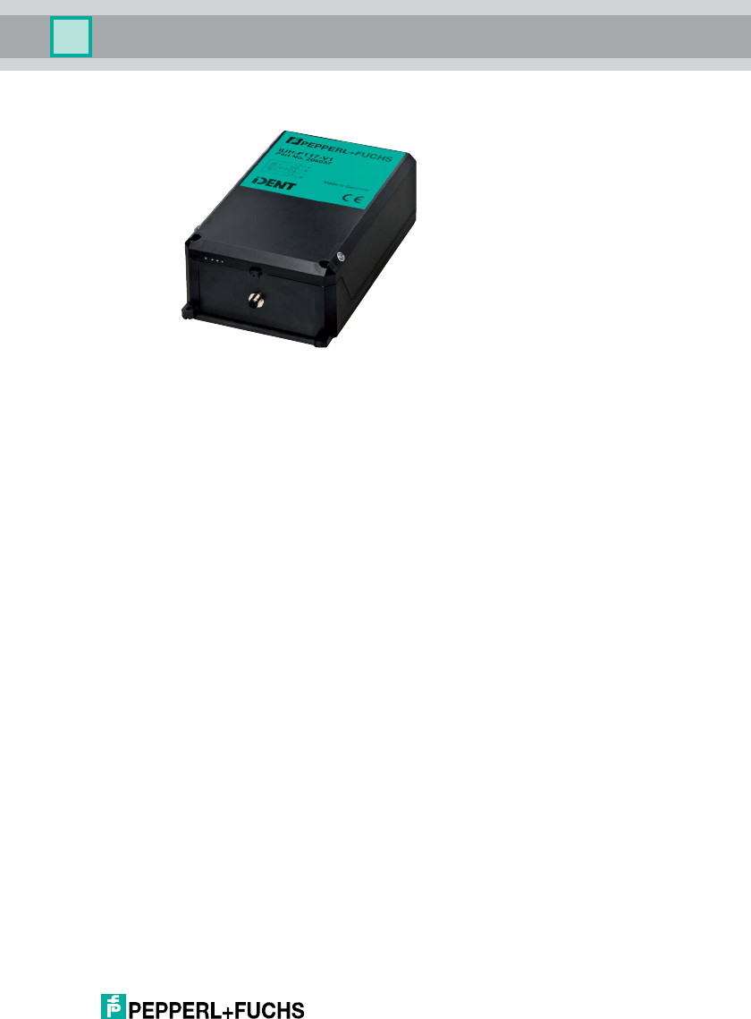
IUH-F117-V1-EU
IUH-F117-V1-US
IUH-F117-V1-CN
R/W head for IDENTControl
FACTORY AUTOMATION
MANUAL

With regard to the supply of products, the current issue of the following document is applicable: The
General Terms of Delivery for Products and Services of the Electrical Industry, published by the
Central Association of the Electrical Industry (Zentralverband Elektrotechnik und Elektroindustrie
(ZVEI) e.V.) in its most recent version as well as the supplementary clause: "Expanded reservation
of proprietorship"
IUH-F117-V1-*

IUH-F117-V1-*
Contents
2012-09
3
1 Introduction......................................................................... 5
2 Declaration of Conformity ................................................. 6
3 Safety................................................................................... 7
3.1 Symbols relevant to safety ............................................................................7
3.2 Intended Use ................................................................................................7
3.3 General notes on safety.................................................................................8
4 Product Description ........................................................... 9
4.1 UHF general .................................................................................................9
4.1.1 Advantages of UHF ..................................................................................9
4.1.2 Permissible Operating Capacity of UHF ...................................................9
4.1.3 Permissible Frequency Range of UHF......................................................9
4.1.4 Applications for UHF systems...................................................................9
4.1.5 Memory Structure of a Tag in Accordance with ISO 18000-6C/
EPC Class 1 Gen 2 .................................................................................10
4.1.6 Electronic product code EPC .................................................................11
4.1.7 Unique numbering as per ISO ................................................................12
4.1.8 Influence of various materials on the sensing range ...............................13
4.1.9 Countries of Use.....................................................................................14
4.1.10 Dense Reader Mode DRM .....................................................................14
4.1.11 Europe....................................................................................................15
4.1.12 China......................................................................................................15
4.1.13 USA........................................................................................................16
4.1.14 RFID Frequency Bands ..........................................................................16
4.1.15 Relevant UHF standards ........................................................................16
4.2 General Functions and Features..................................................................17
4.3 Indicators and Controls ...............................................................................17
4.4 Connection .................................................................................................18
4.5 Scope of Delivery........................................................................................18
4.6 Accessories ................................................................................................18
4.6.1 IDENTControl .........................................................................................18
4.6.2 Read/Write Tags .....................................................................................19
4.6.3 Connection cable for R/W heads and trigger sensors ............................19
4.6.4 Cable connectors for the power supply ..................................................20
4.6.5 Installation accessories ..........................................................................20

2012-09
4
IUH-F117-V1-*
Contents
5 Installation ........................................................................ 21
5.1 Storage and transport................................................................................. 21
5.2 Unpacking .................................................................................................. 21
5.3 Mounting .................................................................................................... 21
5.3.1 Orientation in the room .......................................................................... 22
5.3.2 Minimum and Maximum Distances........................................................ 22
5.3.3 Polarization ............................................................................................ 23
5.4 Connection................................................................................................. 24
5.5 EMC concept ............................................................................................. 24
6 Commissioning ................................................................ 26
6.1 Connection................................................................................................. 26
6.2 Device settings........................................................................................... 26
6.3 Operating via the Command Interface ........................................................ 26
7 Operation .......................................................................... 31
7.1 General....................................................................................................... 31
7.2 Read/Write Commands .............................................................................. 31
7.3 Configuration commands ........................................................................... 34
7.3.1 ChangeTag Command........................................................................... 34
7.3.2 ReadParam/WriteParam Commands..................................................... 35
7.3.3 ParamTyp............................................................................................... 36
7.4 Legend ....................................................................................................... 40
7.5 Fault/status messages................................................................................ 41
8 Service and Maintenance................................................ 42
9 Troubleshooting ............................................................... 43
10 ASCII table ........................................................................ 44
11 Appendix........................................................................... 45
11.1 Dimensions ................................................................................................ 45
11.2 Technical Data............................................................................................ 45
11.3 Detection Range ........................................................................................ 46

IUH-F117-V1-*
Introduction
2012-09
5
1Introduction
Congratulations
You have chosen a device manufactured by Pepperl+Fuchs. Pepperl+Fuchs
develops, produces and distributes electronic sensors and interface modules for
the market of automation technology on a worldwide scale.
Before you install this device and put it into operation, please read the operating
instructions thoroughly. The instructions and notes contained in this operating
manual will guide you step-by-step through the installation and commissioning
procedures to ensure trouble-free use of this product. By doing so, you:
■guarantee safe operation of the device
■can utilize the entire range of device functions
■avoid faulty operation and the associated errors
■reduce costs from downtimes and incidental repairs
■increase the effectiveness and operating efficiency of your plant.
Store this operating manual somewhere safe in order to have it available for future
work on the device.
After opening the packaging, please ensure that the device is intact and that the
package is complete.
Symbols used
The following symbols are used in this manual:
Handling instructions
You will find handling instructions beside this symbol
Contact
If you have any questions about the device, its functions, or accessories, please
contact us at:
Pepperl+Fuchs GmbH
Lilienthalstraße 200
68307 Mannheim
Telephone: +49 621 776-4411
Fax: +49 621 776-274411
E-Mail: fa-info@pepperl-fuchs.com
Note!
This symbol draws your attention to important information.

2012-09
6
IUH-F117-V1-*
Declaration of Conformity
2 Declaration of Conformity
All products were developed and manufactured under observance of the
applicable European standards and guidelines.
The product manufacturer, Pepperl+Fuchs GmbH, 68307 Mannheim, has a
certified quality assurance system that conforms to ISO 9001.
NOTE:
This equipment has been tested and found to comply with the limits for a Class A
digital device, pursuant to part 15 of the FCC Rules. These limits are designed to
provide reasonable protection against harmful interference when the equipment is
operated in a commercial environment. This equipment generates, uses, and can
radiate radio frequency energy and, if not installed and used in accordance with
the instruction manual, may cause harmful interference to radio communications.
Operation of this equipment in a residential area is likely to cause harmful
interference in which case the user will be required to correct the interference at
his own expense.
Note!
A Declaration of Conformity can be requested from the manufacturer.
FCC ID: IREIUH-F117-V1
This device complies with Part 15 of the FCC Rules. Operation is subject to the following
two conditions:
1. this device may not cause harmful interference, and
2. this device must accept any interference received, including interference that may cause
undesired operation.
Notice:
Changes or modifications made to this equipment not expressly approved by
Pepperl+Fuchs GmbH may void the FCC authorization to operate this equipment.
ISO9001
IUH-F117-V1-*
Safety
2012-09
7
3Safety
3.1 Symbols relevant to safety
3.2 Intended Use
The IUH-F117-V1-* is a read/write head for passive code and read/write tags.
The IUH-F117-V1-* operates at a frequency in the UHF range (Europe:
865–868 MHz, USA: 902–928 MHz, China: 920–925 MHz).
Always operate the device as described in these instructions to ensure that the
device and connected systems function correctly. The protection of operating
personnel and plant is only guaranteed if the device is operated in accordance
with its intended use.
Read through these instructions thoroughly. Familiarize yourself with the device
before installing, mounting, or operating.
Pepperl+Fuchs GmbH provides no guarantee that the information contained in
this document does not contain third party industrial property rights.
Pepperl+Fuchs GmbH does not issue any licenses to its own or third party patents
or other industrial property rights in this document.
Danger!
This symbol indicates a warning about an immediate possible danger.
In case of ignoring the consequences may range from personal injury to death.
Warning!
This symbol indicates a warning about a possible fault or danger.
In case of ignoring the consequences may cause personal injury or heaviest
property damage.
Caution!
This symbol indicates a warning about a possible fault.
In case of ignoring the devices and any connected facilities or systems may be
interrupted or fail completely.
Note!
The installation recommendations made in this document are based on favorable
basic conditions. Pepperl+Fuchs GmbH provides no guarantee of correct function
in environments belonging to other systems.
Warning!
Minimum distance
When installing the device in areas covered under US Code of Federal
Regulations Part 15 a minimum distance of 25 cm between antenna and the
human body must be maintained.

2012-09
8
IUH-F117-V1-*
Safety
3.3 General notes on safety
Only instructed specialist staff may operate the device in accordance with the
operating manual.
User modification and or repair are dangerous and will void the warranty and
exclude the manufacturer from any liability. If serious faults occur, stop using the
device. Secure the device against inadvertent operation. In the event of repairs,
return the device to your local Pepperl+Fuchs representative or sales office.
The connection of the device and maintenance work when live may only be
carried out by a qualified electrical specialist.
The operating company bears responsibility for observing locally applicable
safety regulations.
Store the not used device in the original packaging. This offers the device optimal
protection against impact and moisture.
Ensure that the ambient conditions comply with regulations.
Warning!
Malfunctions with pacemakers
This device does not exceed the permissible limits for electromagnetic fields.
Maintain a minimum distance of 25 cm between the device and your pacemaker.
Inadequate distance from the read/write head can result in inhibitions,
reprogramming or incorrect stimulation pulses.
Note!
Disposal
Electronic waste is hazardous waste. When disposing of the equipment, observe
the current statutory requirements in the respective country of use, as well as local
regulations.

IUH-F117-V1-*
Product Description
2012-09
9
4 Product Description
4.1 UHF general
4.1.1 Advantages of UHF
■Large sensing range
■UHF high-temperature transponder available for the automobile industry
■UHF transponders are available as low-cost, space-saving adhesive labels
■High transfer rates
■Large quantities of data transferred, depending on the transponder
4.1.2 Permissible Operating Capacity of UHF
In Europe, a maximum of 2 WERP (+33 dBm ERP in accordance with DIN EN
302208-1) are permitted.
In the USA, a maximum of 4 W areEIRP permitted.
In China, a maximum of 2 W areERP permitted.
4.1.3 Permissible Frequency Range of UHF
The frequency range for UHF, in which the IUH-F117-V1-* read/write head
operates, is:
■865 MHz to 868 MHz in Europe in accordance with DIN EN 302208-1
■902 MHz to 928 MHz in the USA
■920 MHz to 925 MHz in China
4.1.4 Applications for UHF systems
■Identification in galvanic coating or painting systems used in automotive
production,
■Identification of vehicle bodies in final vehicle assembly,
■Palette identification and tracking of goods in the logistics sector and
■Truck identification for access control at loading stations.
2012-09
10
IUH-F117-V1-*
Product Description
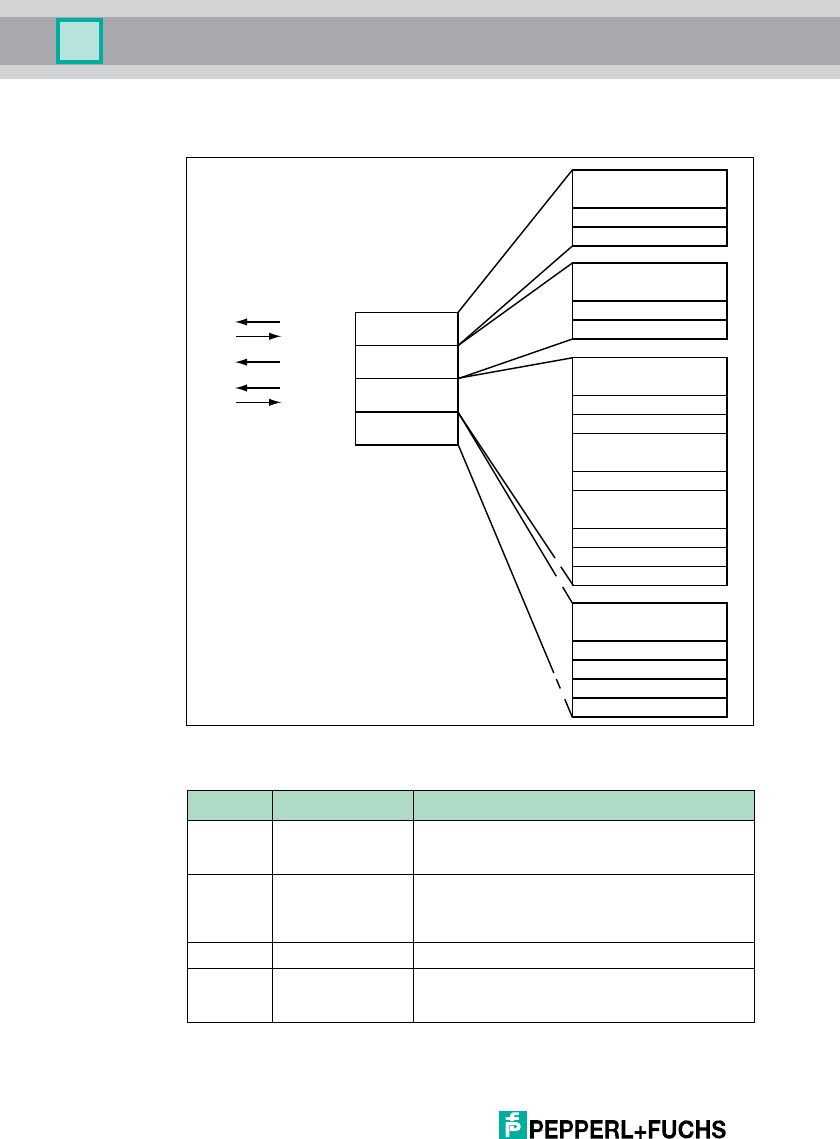
4.1.5 Memory Structure of a Tag in Accordance with ISO 18000-6C/EPC Class
1 Gen 2
The memory module of an EPC-type Class 1 Gen 2 tag is split into 4 segments.
The essential contents of these segments are:
Segment Function Length
Bank 00 Password manager Depending on the tag type, see table "Tag Types
UHF 868 MHz" on page 35"Special read-only code"
column
Bank 01 Unique Item
Identifier (UII)
Electronic Product
Code (EPC)
Depending on the tag type, see table "Tag Types
UHF 868 MHz" on page 35"Special read-only code"
column
Bank 10 Ta g I D (T ID ) 8 byte
Bank 11 User data Depending on the tag type, see table "Tag Types
UHF 868 MHz" on page 35"Special read-only code"
column
USER
TID
UII/EPC
RESERVED
RFU [7:0]
10
h
1F
h
.
.
.
MSB LSB
DSFID [7:0]
00
h
0F
h
TID [15:0]
10
h
1F
h
.
.
.
MSB LSB
TID [31:16]
00
h
0F
h
UII/EPC [N:N-15]
20
h
210
h
2F
h
.
.
.
MSB LSB
PC [15:0]
10
h
1F
h
UII/EPC [15:0]
CRC-16 [15:0]
00
h
0F
h
Access Password [15:0]
30
h
3F
h
.
.
.
MSB LSB
Access Password [31:16]
20
h
2F
h
Kill Password [15:0]
10
h
1F
h
Kill Password [31:16]
00
h
0F
h
Bank 11
Bank 10
Bank 01
Bank 00
SR/ER
SW/EW
SS/ES
SP/EP
SF/EF
.
.
.
Optional XPC_W2 [15:0]
Optional XPC_W2 [15:0]
.
.
.
220
h
21F
h
22F
h
Memory module
Commands
IUH-F117-V1-*

IUH-F117-V1-*
Product Description
2012-09
11
Bank 00
The segment bank 00 contains the password manager, comprising the access
password and the kill password. This range is not currently supported by IUH-
F117-V1-*.
Bank 01
In addition to the UII, the segment bank 01 contains a calculated checksum CRC
(cyclic redundancy check) for verifying data on the tag and the protocol control
(PC) range. The PC range contains:
■The length of the UII
■The characteristic of the Application Family Identifier (AFI) field
■A bit switch that shows whether the UII contains an EPC or MITL number
sequence in accordance with ISO (see chapter 4.1.6, see chapter 4.1.7&
see chapter 7.3)
■A bit switch that shows whether data is stored in segment bank 11 (if
present)
All data in segment bank 01 are automatically set by IUH-F117-V1-*. The data is
addressed via the commands single read special read-only code (SS), single
write special read-only code (SP), enhanced read special read-only code (ES)
and enhanced write special read-only code (EP). (see "Single Read Special
Read-Only Code SS" on page 31, see "Single Write Special Read-Only Code SP"
on page 32, see "Enhanced Read Special Read-Only Code ES" on page 32& see
"Enhanced Write Special Read-Only Code EP" on page 32)
Bank 10
Segment bank 10 contains the part number and the serial number of the tag. This
data is permanently stored without being changed.
The data in segment bank 10 can be read out via the commands single read read-
only code (SF) and enhanced read read-only code (EF). (see "Single read fixcode
SF" on page 31& see "Enhanced read fixcode (EF)" on page 31)
Bank 11
Segment bank 11 contains an area to which the user has free access. Depending
on chip type, this area has different sizes or is not present.
The data in segment bank 11 is addressed via the commands single read words
(SR), single write words (SW), enhanced read words (ER) and enhanced write
words (EW). (see "Single Read Words SR" on page 32, see "Single Write Words
SW" on page 33, see "Enhanced Read Words ER" on page 33& see "Enhanced
Write Words EW" on page 33)
4.1.6 Electronic product code EPC
The electronic product code is a unique code composed of a series of digits. This
series of digits has a defined structure and a length of 64 bits, 80 bits, 96 bit or
longer (depending on the EPC identification number used), is stored on the RFID
transponder and uniquely identifies every transponder all over the world.
2012-09
12
IUH-F117-V1-*
Product Description
GS1/EPCglobal developed the system of Electronic Product Codes (EPC) for use
in resource planning. Transponders with a memory for EPC codes are
programmed by the user. The memories of new transponders do not have to
contain valid EPC codes. The EPC numbers are allocated and managed by GS1.
If you require EPC numbers, please contact the respective GS1 branch in your
country (http://www.gs1.com/contact).
The electronic product code has a defined layout that is structured as follows:
1. Header: the header specifies the EPC standard used and contains the se-
ries of digits.
2. Filter value: describes the product unit, e.g., end product, packaging, prod-
uct range.
3. Partition: describes the point at which the EPC manager mentioned below
stops and the object data starts.
4. EPC Manager: allocated series of digits that identify the manufacturer.
5. Object class: series of digits that describe the object, e.g., article number.
6. Serial number: series of digits that identify the article, e.g., consecutive se-
rial numbers of the article.
To work with unique identifications without having to revert to potentially costly
EPC codes, we recommend using the UID and TID of the transponders
programmed permanently into the transponder chips by the semiconductor
manufacturer.
4.1.7 Unique numbering as per ISO
In addition to the Electronic Product Code (EPC), a series of MITL numbers can
also be used as a UII in accordance with ISO. MITL stands for Multi Industry
Tra ns p o r t L a be l.
Example:
25SLHUNIK15000905130035
The series consists of the following
1. Data identifier
25S describes a unique object.
2. Unique company ID
LH describes die issuing authority, in this example the European Health In-
dustry Business Communications Council "EHIBCC."
Header
Filter value
Partition EPC Manager Object class Serial number
Length
Value
1 = decimal
8 Bit 3 Bit 3 Bit 28 Bit 24 Bit 36 Bit
0011 1001 010 004 50123456 001234567 1234567891234
11 1 1
Note!
The TID on some transponder types is not unique. See table "Tag Types UHF 868
MHz" on page 35.
IUH-F117-V1-*
Product Description
2012-09
13
UNIK describes the company, in this case "UNIK."
3. Serial number
15000905130035 is the unique serial number.
The relevant standards relating to unique identification include ISO/IEC 15434,
ISO/IEC 15459-1 to 8 and ISO/IEC TR 29162 (in preparation).
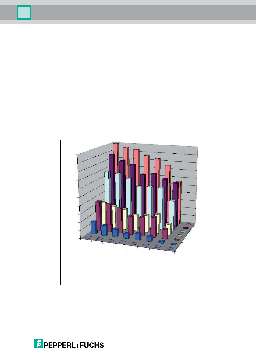
4.1.8 Influence of various materials on the sensing range
In the UHF range, the nature of the surrounding area and the surface to which the
transponder is secured have a serious influence on the range that the system can
attain. The UHF transponder cannot be mounted on metal without requiring
adaptations. Glass has a negative influence on the sensing range when used as a
mounting surface. If a UHF transponder is mounted on damp material, the
sensing range is much poorer than the range of a transponder mounted on dry
material. The mounting surface often affects the read range much more than the
material between the transponder and the read/write head. The graph shows the
effect of different materials on the sensing range.
0 %
10 %
20 %
30 %
40 %
50 %
60 %
70 %
80 %
90 %
100 %
Material
underground
Material between transponder and
read / write head
Foam material
Film
Cardboard (dry)
Cardboard (wet)
Wood (dry)
Glass
Metal
Ai
r
Film
Cardboard (dr
y
)
Cardboard (wet)
Wood (dr
y
)
Foam material
Glass
Metal
2012-09
14
IUH-F117-V1-*
Product Description
4.1.9 Countries of Use
The IUH-F117-V1-* read/write head has transmission license in accordance with
DIN EN 302208-2.
A list of countries of use can be found in "ERC Recommendation ERC/REC70-
03". These are available on the "European Communications Office ERO" website
under www.ero.dk as recommendation. The currently applicable countries of use
are listed in this document under Appendix 11.
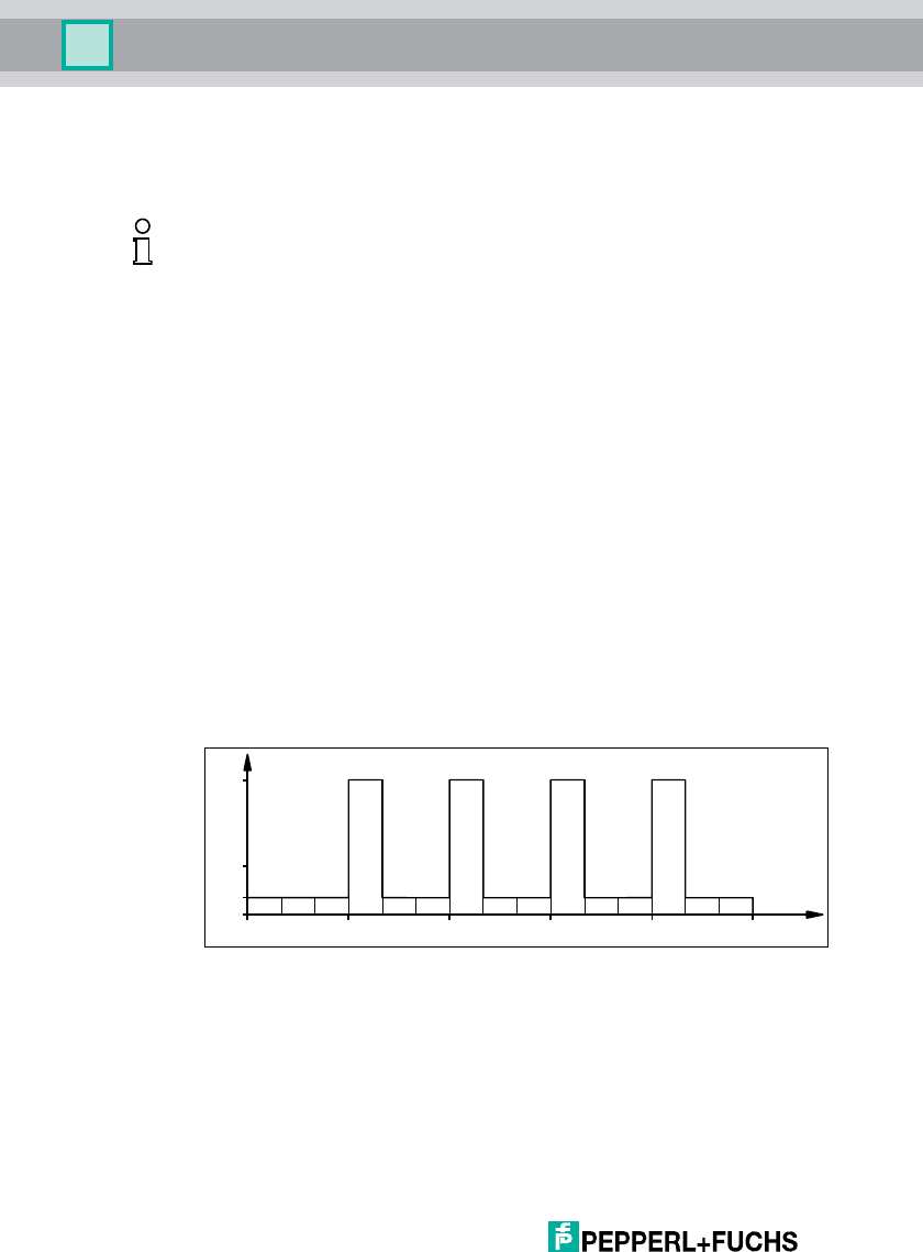
4.1.10 Dense Reader Mode DRM
A special operating mode for read/write tags in accordance with the UHF Gen 2
specification allows several read/write heads to be operated next to each other
without interference.
Europe
In line with EPC Global and ETSI EN 302208, only channels 4, 7, 10 and 13 are
used in this mode for transmission for the IUH-F117-V1-EU read/write head
(read/write head -> read/write tag communication path). The transmission power
is max. 2 Werp.
Figure 4.1
The read/write head can therefore only use preset channels. The response from
the read/write tag appears via the frequency offset, which is achieved by the
modulation used in this mode on the two adjacent channels. The IUH-F117-V1-
EU read/write head transmits on the four transmission channels 4, 7, 10 and 13,
provided that these channels have been preset. Due to the high level difference
between the transmission channels and the response channels, this technology
offers major benefits for reusing frequencies. This requires minimum distances
and therefore a minimum coupling between the antennas of adjacent read/write
heads to be maintained.
Note!
If you wish to use a device in a country in which this standard is not effective,
make sure beforehand that the following values for the device are consistent with
the local conditions:
■Frequency band
■Power level
■The described modulation and operating modes must be permitted
W
erp
0.1
2.0
865.0 868.0865.6 867.4 MHz
0.5
123456789101112131415 Channel
866.8866.2
IUH-F117-V1-*
Product Description
2012-09
15
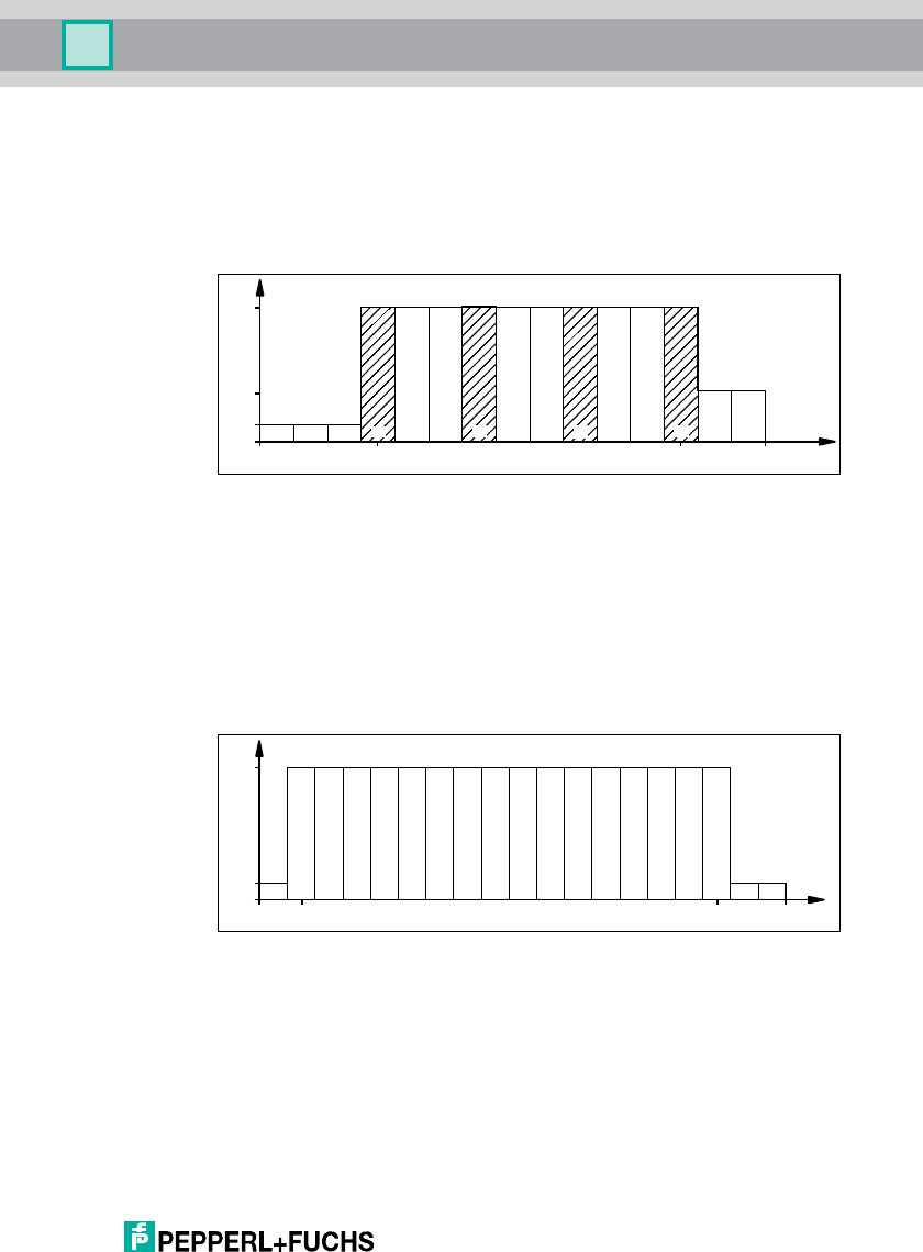
4.1.11 Europe
The IUH-F117-V1-EU read/write head has wireless approval to DIN EN 302208-2.
The read/write head is operated in dense reader mode (DRM). This operating
mode in accordance with the UHF Gen 2 specification allows several read/write
heads to be operated next to each other in the permitted channels (4, 7, 10 and
13) without interference.
Figure 4.2
4.1.12 China
In China, the frequency ranges 840–845 MHz and 920–925 MHz are available for
UHF-RFID readers. This read/write head uses the 920–925 MHz range. The
range is split into 20 channels, each with a bandwidth of 250 kHz. On channels 0,
1, 18, and 19, only 100 mWerp of transmission power are permitted at the edge of
the spectrum. On channels 2–17, 2 W areerp permitted. The transmission power
can be set. It is stated in Werp . FHSS with a maximum 2 seconds retention time is
used.
Figure 4.3
0.1
2.0
865.0 868.0865.7 867.5 MHz
0.5
123456789101112131415 Channel
Werp
Channel
0.1
2.0
920 925920.625 924.125 MHz
Werp
1 2 3 4 5 6 7 8 9 10111213141516171819
2012-09
16
IUH-F117-V1-*
Product Description
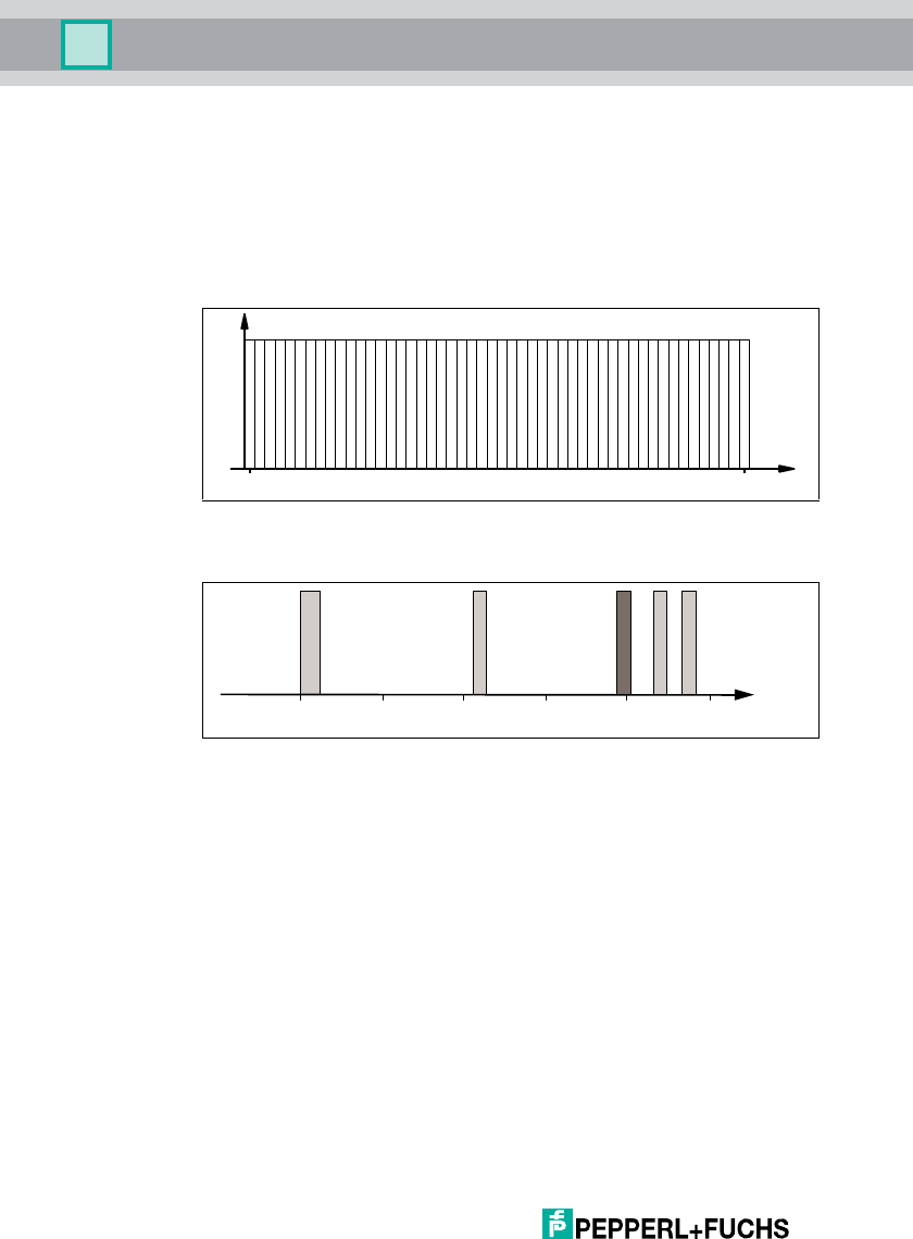
4.1.13 USA
The ISM band from 902 to 928 MHz is available in the USA. The band is split into
50 channels, each with a 500 kHz bandwidth. FHSS with a maximum retention
time of 4 seconds is employed. All channels must be used. Channel restriction is
not permitted.
In contrast to the read/write heads for Europe and China, the transmission power
is stated in Weirp .
Figure 4.4
4.1.14 RFID Frequency Bands
■100–135 kHz: Low frequency LF
■13.56 MHz: High frequency HF
■865–868 MHz (Europe), 902–928 MHz (USA), 920–925 MHz (China):
ultra-high frequency UHF
■2.45 GHz and 5.8 GHz: Microwave MW
4.1.15 Relevant UHF standards
European radio standards: EN 300220 and EN 302208
Application recommendations for RFID labels, information on recyclability,
installation of readers and antennas: ISO/IEC TR 24729 parts 1-4
Installation and commissioning of UHF RFID systems: ETSI TR 102436
Radio interface description "UHF Gen2", "Electronic Product Code" (EPC):
ISO/IEC 18000-6, Annex 1 in part C
0.2
4.0
902.75 927.25MHz
Channel
W
eirp
10 15 2051 30354025 45 50
Frequency
[MhZ]
125 kHz
2,45 GHz
13,56 MHz
5,8 GHz
868/915 MHz
0,1
LF
110
HF
100 1000
UHF
10000
MW
IUH-F117-V1-*
Product Description
2012-09
17
4.2 General Functions and Features
Functions
The read/write head IUH-F117-V1-* was developed for writing and reading
passive read/write tags with a UHF range operating frequency.
Detection range
An integrated, highly-sensitive transmission and receiver unit enables a read/write
tag detection range of up to 6 meters and permits tag protocols in accordance
with EPC Class1 Gen2 and ISO 18000-6 C. Special blocking options support the
operation of closely located read/write heads. (see chapter 4.1.10)
Decoding
The integrated powerful high-performance module decodes Miller-coded tag
signals with 80 kbit/s (EU).
(Miller-coding = side band modulation for the dense reader mode)
Features
The IUH-F117-V1-* read/write head has the following features:
■2 dual LEDs for function display
■Industrial housing
■Interference-free operation, even with other read/write heads in the direct
vicinity
■Connects to the IDENTControl via connector V1 (M12 x 1)
■Protects against failures (such as antenna short-circuit) and electrostatic
discharge
4.3 Indicators and Controls
The IUH-F117-V1-* read/write head has two dual LEDs (green/yellow). The two
LEDs are located on opposite sides and are clearly visible. The various indicators
mean:
■Green: power on
■Flashing green: attempting to read/write
■Yellow: command executed
2012-09
18
IUH-F117-V1-*
Product Description
4.4 Connection
The read/write head is connected to the IDENTControl interface via an M12 x 1
connector.
4.5 Scope of Delivery
■Read/write head IUH-F117-V1-*
■Manual
4.6 Accessories
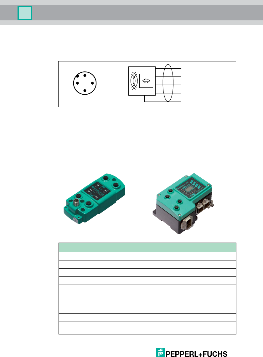
4.6.1 IDENTControl
The IUH-F117-V1-* can be connected to Pepperl+Fuchs IDENTControl control
interfaces as a read/write head.
Shield
+
A
-
B
1
2
3
4
1
42
3
Interface Designation
4 read/write heads:
Ethernet IC-KP-B17-AIDA1
2 read/write heads:
Ethernet IC-KP2-2HB17-2V1D
CC-Link IC-KP2-2HB18-2V1
1 read/write head:
PROFIBUS IC-KP2-1HB6-V15B
IC-KP2-2HB6-V15B
Ethernet IC-KP2-1HB17-2V1D
Serial IC-KP2-1HRX-2V1
IC-KP2-2HRX-2V1
Table 4.1 IDENTControl
IUH-F117-V1-*
Product Description
2012-09
19
4.6.2 Read/Write Tags
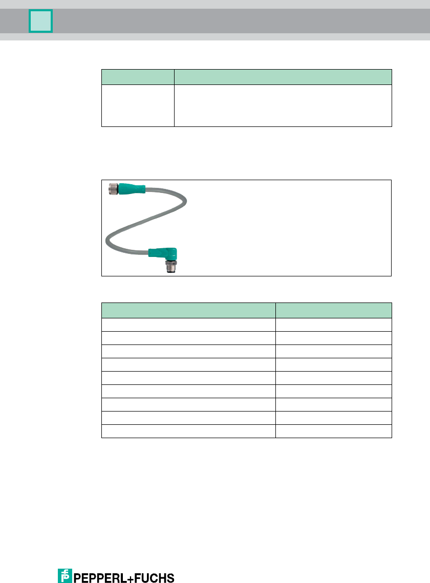
4.6.3 Connection cable for R/W heads and trigger sensors
Compatible connection cables with shielding are available for connecting the R/W
heads and trigger sensors.
Figure 4.5
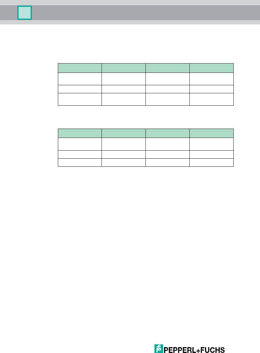
Ty p e Designation
ISO 18000-6 C IUC72-C8-T14
IUC72-F151
IUC72-F152
IUC73-F153
IUC76-F157-M
Accessories Description
2 m long (straight female, angled male) V1-G-2M-PUR-ABG-V1-W
5 m long (straight female, angled male) V1-G-5M-PUR-ABG-V1-W
10 m long (straight female, angled male) V1-G-10M-PUR-ABG-V1-W
20 m long (straight female, angled male) V1-G-20M-PUR-ABG-V1-W
Field attachable female connector, straight, shielded V1-G-ABG-PG9
Field attachable male connector, straight, shielded V1S-G-ABG-PG9
Field attachable female connector, angled, shielded V1-W-ABG-PG9
Field attachable male connector, angled, shielded V1S-W-ABG-PG9
Dummy plug M12x1 VAZ-V1-B
2012-09
20
IUH-F117-V1-*
Product Description
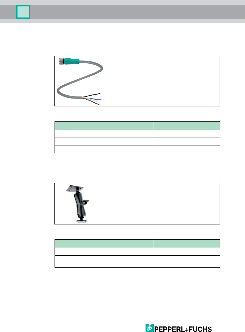
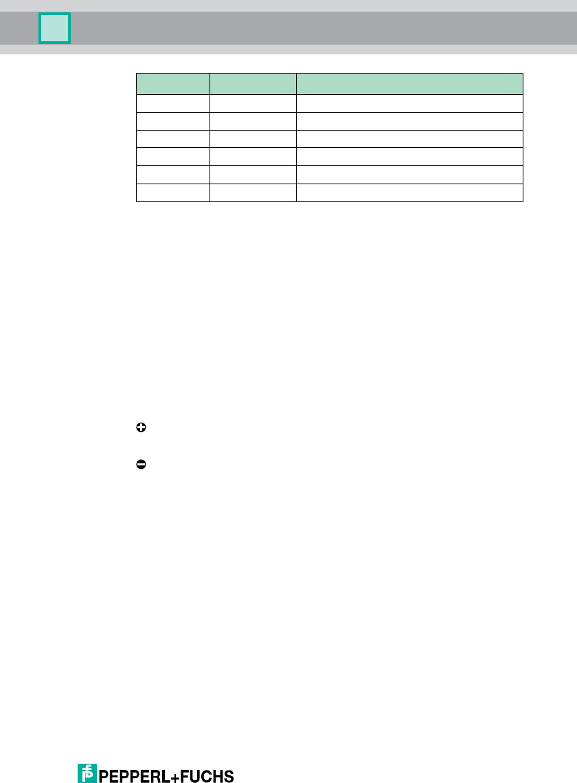
4.6.4 Cable connectors for the power supply
Compatible M12 sockets with an open cable end for connecting the
IDENTControl to a power supply are available in different lengths.
Figure 4.6
4.6.5 Installation accessories
Two different mounting brackets are available to mount the read/write head on a
wall or pole.
Figure 4.7 IUZ-MH10
Accessories Designation
Length 2 m (straight socket) V1-G-2M-PUR
Length 5 m (straight socket) V1-G-5M-PUR
Length 10 m (straight socket) V1-G-10M-PUR
Accessories Designation
Mounting bracket for wall attachment IUZ-MH10
Mounting bracket for pipe installation
(pipe with maximum diameter of 40 mm)
IUZ-MH11

IUH-F117-V1-*
Installation
2012-09
21
5 Installation
5.1 Storage and transport
For storage and transport purposes, package the unit using shockproof
packaging material and protect it against moisture. The best method of protection
is to package the unit using the original packaging. Furthermore, ensure that the
ambient conditions are within allowable range.
5.2 Unpacking
Check the product for damage while unpacking. In the event of damage to the
product, inform the post office or parcel service and notify the supplier.
Check the package contents with your purchase order and the shipping
documents for:
■Delivery quantity
■Device type and version in accordance with the type plate
■Accessories
■Quick start guide
Retain the original packaging in case you have to store or ship the device again at
a later date.
Should you have any questions, please contact Pepperl+Fuchs.
5.3 Mounting
The read/write head was designed for mounting on walls or brackets in internal
areas. Please always secure the read/write head to the holes provided on the
housing. The preferred installation position is with the cable connection vertical
facing downwards.
Note!
Please note that radio waves in the UHF range do not disperse evenly due to
reflections on objects in the surrounding environment. Aligning the transponder
correctly is therefore extremely important.
2012-09
22
IUH-F117-V1-*
Installation
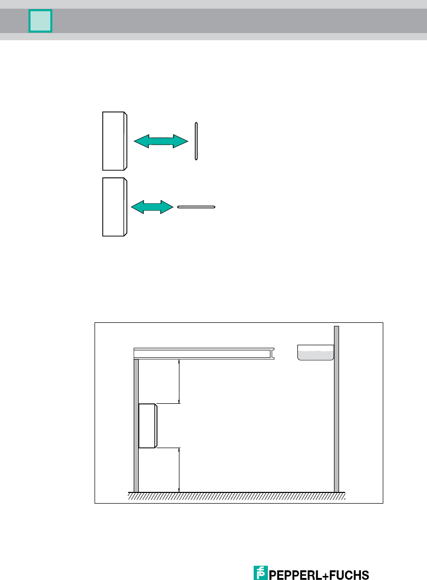
5.3.1 Orientation in the room
The alignment of the antennas on the data carrier in relation to the antenna on the
read/write head influences the sensing range of the system. Therefore, make sure
that the antennas are aligned parallel to one another.
5.3.2 Minimum and Maximum Distances
When positioning the read/write head, please observe the minimum distances.
The lateral distance between the read/write head and metals or liquids should be
at least 50 cm. The distance between the read/write head and the ground should
also be at least 50 cm. The mounting surface material does not affect the
read/write head.
Figure 5.1
Maximum sensing range
Minimum sensing range
liquid
metal support
min. 50 cmmin. 50 cm
IUH-F117-V1-*
Installation
2012-09
23
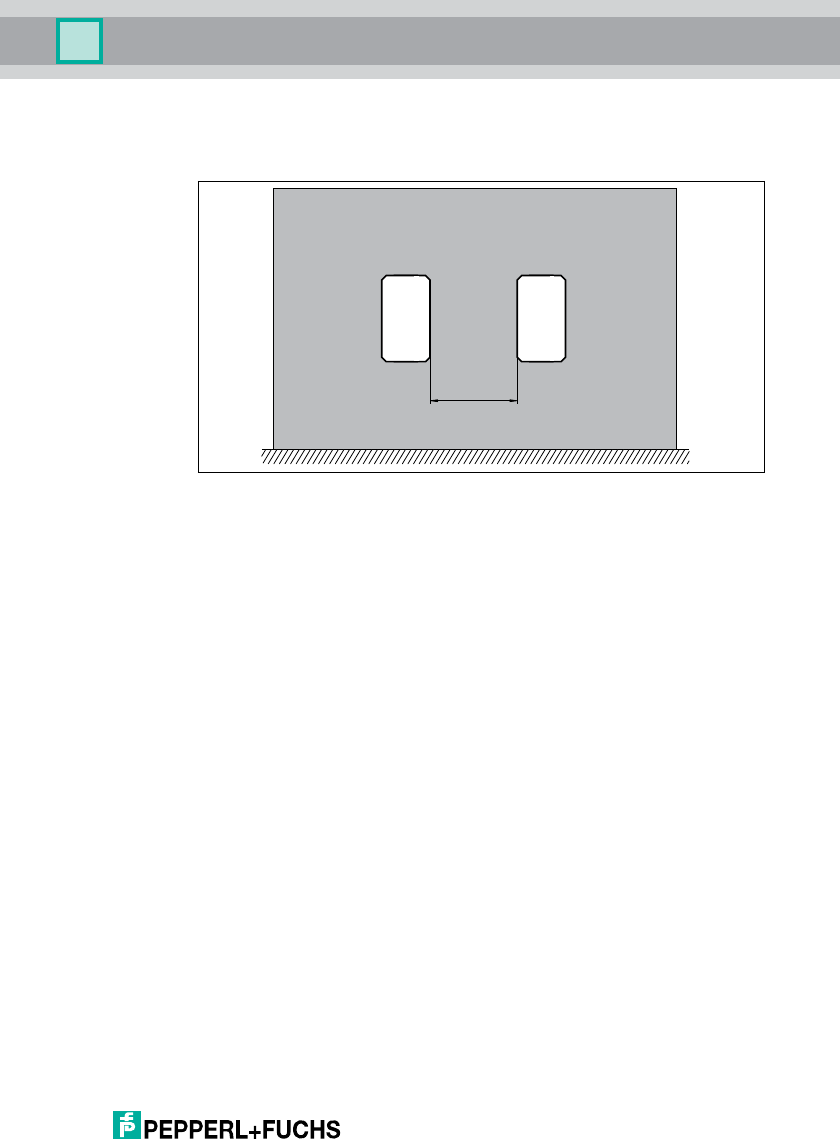
If you wish to position multiple read/write heads next to each other or above each
other, the distance should be no less than 20 cm between each unit. A minimum
distance of 50 cm is reasonable.
Figure 5.2
5.3.3 Polarization
The polarization of an electromagnetic wave emitted from an antenna depends on
the electromagnetic field component and the spatial position of the antenna. A
fundamental distinction is drawn between linear and circular polarization. The
polarization of the read/write head must be adapted to the polarization of the
transponder in order for a UHF system to utilize the full sensing range. Refer to the
corresponding data sheet for details on the polarization of the transponder.
■Linear polarization: the direction of the vector of an electromagnetic field
component that generates an electromagnetic wave with linear polarization
is always constant. Linear polarization is available in a vertical and
horizontal configuration, which is dependent on the spatial position of the
antenna.
■Circular polarization: the vector of an electromagnetic field component that
generates an electromagnetic wave with circular polarization rotates
around an axis parallel with the beam direction. The rotation of the antenna
around the communication axis has no influence.
The IUH-F117-V1 read/write head is supplied with circular polarization.
Polarization can be changed from circular to linear using the software on the
IDENTControl interface. With linear polarization, the polarization level is aligned
horizontally when the read/write head is mounted in the preferred installation
direction with the cable connection vertical facing downwards.
min. 50 cm
2012-09
24
IUH-F117-V1-*
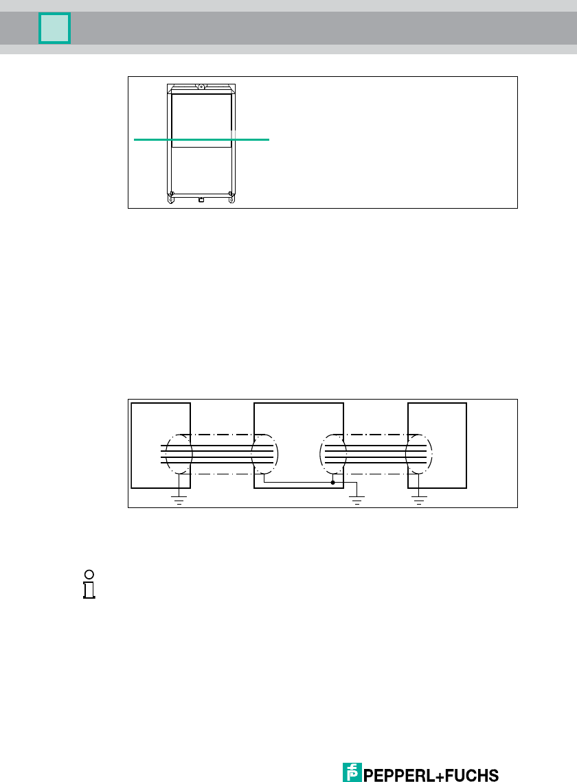
Installation
Figure 5.3 Polarization plane IUH-F117-V1-* with linear polarization
5.4 Connection
Connect the read/write head to the IDENTControl interface using a shielded
connection cable (see chapter 4.6.2). Make sure that the shielding is continuous
to prevent EMC interference. (see chapter 5.5)
5.5 EMC concept
The outstanding noise immunity of the IDENTControl against emission and
immission is based on its consistent shielding design, which uses the principle of
the Faraday cage. Interference is caught in the shield and safely diverted via the
ground connections.
The screening of cables provides for the discharge of electromagnetic
interference. When screening a cable, both sides of the screen must be
connected to the earth with low resistance and low inductance.
The metal enclosure of the IDENTControl and the metal enclosure of the R/W
heads complete the consistent shielding concept.
Polarization plane
write head ControlIDENTControl INTERBUS
Note!
If cables with double shields are used, e.g. wire mesh and metalized foil, the both
shields must be connected together, with low resistance, at the ends when
making up the cable.
Power supply cables are the source of much interference, e.g. from the supply
lines of 3-phase electric motors. For this reason, the parallel laying of power
supply cables with data and signal cables should be avoided, particularly in the
same cable duct.

IUH-F117-V1-*
Installation
2012-09
25
The most important issue here is that the shields are connected to ground with
low resistance and low inductance. The metal enclosure ensures that the
shielding is not interrupted, i.e. the complete electronics system and all routed
cables are located within a Faraday cage.

2012-09
26
IUH-F117-V1-*
Commissioning
6Commissioning
6.1 Connection
When you connect the control interface to the power supply, the PWR/ERR LED
on the device lights up green. If the LED on the device does not light up, the power
supply is connected incorrectly. The LED on the device lights up red when a
device fault occurs. If the PWR/ERR LED flashes red and green alternately after
you connect the IUH-F117-V1 read/write head, the power supply does not offer
sufficient power. If the LED on the read/write head slowly flashes green, the
control interface is configured incorrectly.
6.2 Device settings
You must configure the control interface before commissioning the read/write
head. Read the chapter "Commissioning" in the manual accompanying your
control interface.
Configure the R/W heads with the described system commands.see chapter
7.3.2). To view an example of parameterization see chapter 6.3.
6.3 Operating via the Command Interface
This section shows you how to operate the IUH-F117-V1-* read/write head using
an IDENTControl Compact control interface with serial interface. The
commissioning procedure described relates to the RS 232 interface and involves
a PC. The examples also include the syntax for coding the commands and
parameters via the Ethernet TCP/IP and PROFIBUS interface. Further details
about these codes and the factory setting for your IDENTControl control interface
can be found in the manual.
Caution!
Uncontrollable triggered processes
The plant where the device is installed may be damaged.
Before commissioning, make sure that all processes run in a controlled manner.
Warning!
Incorrect electrical connection
Damage to the device or system caused by incorrect electrical connection
Check all connections in the plant before commissioning the device.
Caution!
Device not configured or configured incorrectly
System failure caused by incorrectly configured device
Configure the device prior to commissioning.

IUH-F117-V1-*
Commissioning
2012-09
27
Commissioning the IDENTControl Compact Control Interface
1. On the PC, open a terminal program (e. g. "Hyperterminal" or the command in-
put window of the "RFIDControl" software supplied with the control interface).
2. Use the terminal program to set the interface configuration to
38400 baud,
8data bits,
no parity,
1 stop bit,
no handshake
protocol: <CHCK><ETX>
3. Switch the device operating voltage off and on.
When the voltage is switched on, the message below appears on the
terminal:
20b.03
2 = Status
0 = IDENTControl channel
b = checksum
.03 = <ETX> = final symbol
The communication from the device to the terminal program functions. The
device is ready for operation.
4. Send the version command VE to the device as confirmation.
The device name, item number and software version of the control
interface and the read/write head are displayed.
Example:
Control interface
00(C) P+F IDENT IC-KP2-2HRX-2V1 #204980 1831464 05/03/10
<CHCK><ETX>
Read/write head
01 IUH-F117-V1 #206057 R010500-F010103 1831569 05/19/10
<CHCK><ETX>
(The software number and the software date may differ. For a description of
the VE command, read the "System commands" section in your control
interface manual.)
If you receive a different response, communication between your PC and the
device has failed. Check the installation and repeat the steps for commissioning
the device.
Note!
Hexadecimal format
In the examples, hexadecimal values are displayed in .03 format. A period is
followed by two characters of hexadecimal code.
.03hex = <ETX>
.41hex = A
2012-09
28
IUH-F117-V1-*
Commissioning
Example:
In the examples below, the read/write head is connected to channel 1 of the
control interface.
The control interface must be connected to an RS 232 interface.
Reading Tags
Set the tag type to IUC80. Do this by transmitting the command change tag (see
"Change Read/Write tag CT" on page 34) to the read/write head. Once you have
set this general tag type, all tags can only be addressed via the read/write
commands single read fixcode and enhanced read fixcode (see "Single read
fixcode SF" on page 31 and see "Enhanced read fixcode (EF)" on page 31) .
Change Read/Write Tag
Transmit the command enhanced read fixcode to the read/write head. The LEDs
on the read/write head flash green.
Enhanced Read Read-Only Code
Move a IUC* tag into the read/write head's detection range. When the tag is
detected and the read-only code is read out, the LED on the read/write head turns
yellow. The read-only code is displayed in the terminal program.
Note!
The device makes no distinction between commands entered in upper and lower
case. Make sure that there are no spaces in all parameters that come after the
command.
Serial Ethernet PROFIBUS
Command: CT180 .00.06.04.02.38.30 .04.02.38.30
Confirmation: - .00.06.04.02.FF.09 .04.02.FF.09
Response: 01 .00.06.04.02.00.0A .04.02.00.0A
Serial Ethernet PROFIBUS
Command: EF1 .00.04.1D.03 .1D.03
Confirmation: - .00.06.1D.03.FF.0B .1D.03.FF.0B
Response: 51 .00.06.1D.03.05.0C .1D.03.05.0C
Table 6.1 No tag in the detection range

IUH-F117-V1-*
Commissioning
2012-09
29
Enhanced Read Read-Only Code
Describing Tags
Set the tag type to IUC72. Do this by transmitting the command change tag (see
"Change Read/Write tag CT" on page 34) to the read/write head.
Change Read/Write Tag
Transmit the command single write special fixcode (see "Single Write Special
Read-Only Code SP" on page 32) to the read/write head while an IUC72 tag is
located within the detection range.
Single Write Special Read-Only Code
As confirmation, read out the read-only code of the IUC72 tag within the
read/write head's detection range via the command single read special fixcode
(see "Single Read Special Read-Only Code SS" on page 31).
Single Read Special Read-Only Code
Serial Ethernet PROFIBUS
Command: EF1 .00.04.1D.03 .1D.03
Confirmation: - .00.06.1D.03.FF.36 .1D.03.FF.36
Response: 01.E0.04.26.70.18.
01.00.00
.00.0E.1D.03.00.37.
E0.04.26.70.18.01.
00.00
.1D.03.00.37.E0.04.
26.70.18.01.00.00
Table 6.2 Tag in the detection range
Serial Ethernet PROFIBUS
Command: CT172 .00.06.04.02.37.32 .04.02.37.32
Confirmation: - .00.06.04.02.FF.15 .04.02.FF.15
Response: 01 .00.06.04.02.00.16 .04.02.00.16
Serial Ethernet PROFIBUS
Command: SP10D10.08.33.B2.
DD.D9.04.80.35.05.
00.00
.00.13.0D.D3.00.00.
31.30.08.33.B2.DD.
D9.04.80.35.05.00.
00
.0D.D3.00.00.31.30.
08.33.B2.DD.D9.04.
80.35.05.00.00
Confirmation: - .00.06.0D.D3.FF.2D .0D.D3.FF.2D
Response: 01 .00.06.0D.03.00.2E .0D.03.00.2E
Serial Ethernet PROFIBUS
Command: SS10 .00.04.0A.02 .0A.02
Confirmation: - .00.04.0A.02.FF.2F .0A.02.FF.2F
Response: 0110.08.33.B2.DD.
D9.04.80.35.05.00.
00
.00.13.0A.02.00.30.
31.30.08.33.B2.DD.
D9.04.80.35.05.00.
00
.0A.02.00.30.31.30.
08.33.B2.DD.D9.04.
80.35.05.00.00
2012-09
30
IUH-F117-V1-*
Commissioning
Example of parameterization:
Setting and requesting the read/write head's transmission power.
Read out the read/write head's transmission power with the read param PT:
Use the write param PT to change the read/write head's transmission power to
500 mW:
Serial Ethernet PROFIBUS
Command: RP1UPT .00.09.BE.03.55.50.
54.00.00
.BE.03.55.50.54.00.
00
Confirmation: - .00.06.BE.03.FF.3E .BE.03.FF.3E
Response: 01.07.D0 .00.08.BE.03.00.3F.
07.D0
.BE.03.00.3F.07.D0
Serial Ethernet PROFIBUS
Command: WP1UPT.00.02.01.
F4
.00.0B.BF.03.55.50.
54.00.02.01.F4
.BF.03.55.50.54.04.
00.02.01.F4
Confirmation: - .00.06.BF.03.FF.11 .BF.03.FF.11
Response: 01 .00.06.BF.03.00.12 .BF.03.00.12

IUH-F117-V1-*
Operation
2012-09
31
7Operation
7.1 General
The sections below contain the details on the commands that specifically address
the read/write head IUH-F117-V1-*. The commands are described using the
example of an IDENTControl control interface with serial interface. All other
generally applicable commands and error or status messages can be found in the
manual for your IDENTControl control interface.
Display
Angle brackets contain the abbreviated meaning of a command structure
Square brackets with the index 10 describe a decimal number
The index hex describes a hexadecimal number
7.2 Read/Write Commands
Single read fixcode SF
One attempt is made to read a read only code.
Enhanced read fixcode (EF)
This command makes continuous attempts to read a read only code until
successful. If a read only code is read, a signal is sent once to the control
interface. If there is no read only code in the detection area or the transponder
leaves the detection area before the read only code is read, a status 5 message is
sent to the control interface in response.
Single Read Special Read-Only Code SS
This command reads the UII segment from tags from type 72 (EPC Class 1 Gen2)
For the length of an EPC code, set <Length> = 00. The actual length of the EPC
code is defined during the write operation and stored on the tag.
<FData>: <PC> & <UII>
Example:
SS1 0 reads the EPC code.
Command: SF <ChanNo> <CHCK> <ETX>
Response: <Status> <Fixcode> <CHCK> <ETX>
Command: EF <ChanNo> <CHCK> <ETX>
Response: <Status> <Fixcode> <CHCK> <ETX>
Command: SS <ChanNo> <Length> <CHCK> <ETX>
Response: <Status> <FData> <CHCK> <ETX>

2012-09
32
IUH-F117-V1-*
Operation
Enhanced Read Special Read-Only Code ES
This command continuously attempts to read the UII segment of tags from type 72
(EPC Class 1 Gen2). If a UII is read, this is reported once to the control interface. If
there is no UII in the detection range or if the tag leaves the detection range before
the UII is read, a status 5 is reported to the evaluation unit as a response.
For the length of an EPC code, set <Length> = 00. The actual length of the EPC
code is defined during the write operation and stored on the tag.
<FData>: <PC> & <UII>
Single Write Special Read-Only Code SP
This command writes an n-byte long EPC code to tags from type 72 (EPC Class 1
Ge n 2 )
Set for <Length> = Length <FData>
<FData> = <PC> & <UII>
Example:
SP1E.30.00.30.05.FB.63.AC.1F.36.81.EC.88.04.68 writes for <PC> the value
.30.00 and the EPC code ".30.05.FB.63.AC.1F.36.81.EC.88.04.68" with a length
of 12 bytes on channel 1.
Enhanced Write Special Read-Only Code EP
This command writes an n-byte long EPC code once to tag type 72 (EPC Class 1
Gen2) and then permanently reads out the EPC code.
Set for <Length> = Length <FData>
<FData> = <PC> & <UII>
Single Read Words SR
One attempt is made to read, <WordNum> 32-bit words from address
<WordAddr>.
Command: ES <ChanNo> <Length> <CHCK> <ETX>
Response: <Status> <FData> <CHCK> <ETX>
Command: SP <ChanNo> <Length> <FData> <CHCK> <ETX>
Response: <Status> <CHCK> <ETX>
Command: EP <ChanNo> <Length> <FData> <CHCK> <ETX>
Response: <Status> <CHCK> <ETX>
Command: SR <ChanNo> <WordAddr> <WordNum> <CHCK> <ETX>
Response: <Status> <Data> <CHCK> <ETX>

IUH-F117-V1-*
Operation
2012-09
33
Enhanced Read Words ER
An attempt is made until <WordNum> 32-bit words are successfully read from the
address <WordAddr>. Only changing data is transferred via the interface. When a
read/write tag leaves the read range, status 5 is output.
Single Write Words SW
One attempt is made to write <WordNum> 32-bit words from the address
<WordAddr>.
Enhanced Write Words EW
This command behaves in the same way as the write words command. When a
read/write tag leaves the read range, status 5 is output.
Note!
The memory bank MB parameter defines the bank which this command
accesses. See "Memory Bank MB" on page 40.
Command: ER <ChanNo> <WordAddr> <WordNum> <CHCK> <ETX>
Response: <Status> <Data> <CHCK> <ETX>
Note!
The memory bank MB parameter defines the bank which this command
accesses. See "Memory Bank MB" on page 40.
Command: SW <ChanNo> <WordAddr> <WordNum> <Data> <CHCK> <ETX>
Response: <Status> <CHCK> <ETX>
Note!
The memory bank MB parameter defines the bank which this command
accesses. See "Memory Bank MB" on page 40.
Command: EW <ChanNo> <WordAddr> <WordNum> <Data> <CHCK> <ETX>
Response: <Status> <CHCK> <ETX>
Note!
The memory bank MB parameter defines the bank which this command
accesses. See "Memory Bank MB" on page 40.

2012-09
34
IUH-F117-V1-*
Operation
7.3 Configuration commands
7.3.1 ChangeTag Command
Change Read/Write tag CT
This command tells the R/W system with which read/write tag to communicate.
Example:
CT172 sets TagType to IUC72
CT180 sets TagType to All, permits the read-only code to be read out from all tag
types and hence draw conclusions about the tag actually in use.
The following tag types are currently supported:
Note!
16-Bit Read/Write Commands
The read/write commands SR, ER, SW and EW are interpreted as 16-bit versions
by means of a preceding # symbol.
The 16-bit read/write commands behave in the same way as the 32-bit versions.
■16-bit commands write or read a word with a length of 2 bytes.
■32-bit commands write or read a word with a length of 4 bytes.
Example:
#SW000202ABCD corresponds to SW000101ABCD
Command: CT <ChanNo> <TagType> <CHCK> <ETX>
Response: <Status> <CHCK> <ETX>
Default: TagType = IUC80
Note!
Ta g Ty p e
The CT command automatically sets the parameters that are suitable for the
selected tag.

IUH-F117-V1-*
Operation
2012-09
35
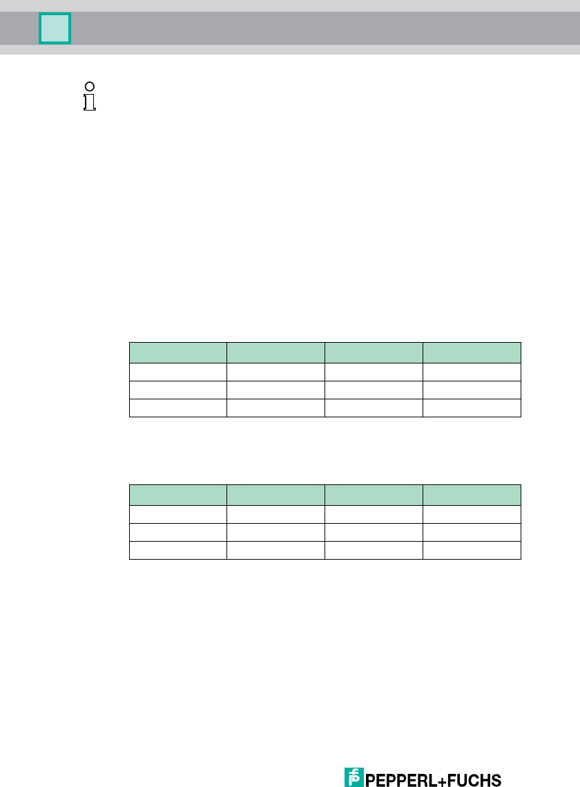
Ta g Ty pe s U HF 8 68 M H z
7.3.2 ReadParam/WriteParam Commands
The configuration commands enable you to set or read the following parameters
via the WriteParam WP and ReadParam RD commands:
■Linear/circular antenna polarization, type=AP (AntennaPolarisation)
■Transmission power, type=PT (PowerTransmit)
■Permitted channels in the Dense Reader Mode, type=CD (ChannelDRM)
■Complete reset of all parameters to the default condition, type=RD (Reset
to Default)
■Anti-collision algorithm on/off, type=AC (AntiCollision)
■Permitted number of read/write attempts in the event of an error, type=TA
(TriesAllowed)
■Number of unsuccessful read attempts up to Status 5, type=E5
(EnhancedStatus5)
■Specified bank on which the write and read commands SR, ER and SW are
accessed, type=MB (Memory Bank)
The parameters are generally saved in the read/write head IUH-F117-V1-* as
non-volatile.
Ta g
type Chip type Details
P+F
desig-
nation TID
Data
[bytes]
Bank 00
[bit]
Special
read-only
code [bit]
Unique
read-only
code
72 EPC Class 1
Ge n 2
NXP UCode-
EPC-G2XM
IUC72 E200600
3 + serial
number
64 32 + 32 240 Ye s
73 EPC Class 1
Ge n 2
Alien Higgs-2 IUC73 E200341
1
-32 + 32 96 No
74 EPC Class 1
Ge n 2
NXP UCode-
EPC-G2
IUC74 E200600
1 + serial
number
28 32 + 32 96 Ye s
75 EPC Class 1
Ge n 2
Impinj Monza
2.0
IUC75 E200107
1
-32 + 32 96 No
76 EPC Class 1
Ge n 2
Alien Higgs-3 IUC76 E200341
2 + serial
number
64 32 + 32 240 Ye s
80 EPC Class 1
Ge n 2
- - Serial
number
- - Max. 96 -
Table 7.1 Tag types 868 MHz

2012-09
36
IUH-F117-V1-*
Operation
Read Param
This command reads configuration parameters from the IQH2-... and IUH-F117-
V1-* read/write head.
Syntax
Write Param
This command writes configuration parameters to the IQH2-... and IUH-F117-V1-*
read/write head.
Syntax
For additional details on the parameters see chapter 7.3.3.
7.3.3 ParamTyp
Stored Configuration SC
This parameter reads out the entire parameterization of the IUH-F117-V1-*
read/write head.
Example:
RP1USC.00.00 reads out the entire parameterization in the following sequence:
Command: RP <ChanNo> <SystemCode> <ParamTyp> <ParamLength> <CHCK>
<ETX>
Response: <Status> <Data> <CHCK> <ETX>
RP <SystemCode><ParamTyp> <ParamLength>
Command: WP <ChanNo> <SystemCode> <ParamTyp> <ParamLength> <Data>
<CHCK> <ETX>
Response: <Status> <CHCK> <ETX>
WP <SystemCode><ParamTyp><ParamLength><Value>
ParamTyp: SC
Byte position Meaning Value range
[0] [1] Device detection IUH-F117-V1-* = .7D.68
IUH-F117-V1 = .7B.51
[2] Default flag Default = .64
Modified = .6D
[3] [4] PT parameter from 100 mW = .00.64
to 2000 mW = .07.D0
[5] CD parameter Number of set channels = 1–4
[6]–[9] Set channels see "Channel DRM CD (IUH-F117-
V1-EU Only)" on page 38
IUH-F117-V1-*
Operation
2012-09
37
Antenna Polarization AP
This parameter switches polarization to linear/circular or reads out the currently
set polarization.
Example:
WP1UAP.00.01L switches the polarization to linear
WP1UAP.00.01C switches the polarization to circular
RP1UAP.00.00 reads out the set polarization
Set the polarization according to the read/write tag used (see chapter 5.3.3).
Higher sensitivity if both the read/write head and the read/write tag are
polarized linearly.
There are gaps in the detection range if the read/write head is polarized
linearly.
Power Transmit PT
This parameter sets the transmission power in mW or reads out the set
transmission power.
The transmission power is stated for IUH-F117-V1-EU and IUH-F117-V1-CN in
Werp . The transmission power is stated in W for the read/write head IUH-F117-
V1-USeirp .
Example:
WP1UPT.00.02.00.64 sets 100 mWerp
WP1UPT.00.02.07.D0 sets 2000 mWerp
RP1UPT.00.00 reads out the set transmission power
[10] TA parameter See "Tries Allowed TA" on page 39
[11] E5 parameter See "Enhanced Status 5 E5" on page 39
[12] AP parameter See "Antenna Polarization AP" on page 37
[13] AC parameter See "Anti-Collision AC" on page 38
[14] QV parameter See "Q-Value QV" on page 39
[15] MB parameter See "Memory Bank MB" on page 40
ParamTyp: AP
Default AP = C
Value range: L, C
ParamTyp: PT
Default: PT = .07.D0bin = 2000 mWerp
Value range: 100–2000 mWerp
100–4000 mWeirp
Byte position Meaning Value range

2012-09
38
IUH-F117-V1-*
Operation
Higher range if the transmission power increases.
Possible overreaches if the transmission power increases.
Adjacent read/write heads might be affected if the range increases.
Channel DRM CD (IUH-F117-V1-EU Only)
This parameter sets the sequence of the channels permitted in the DRM (= dense
reader mode) or reads out the sequence of the permitted channels. Only
channels 4, 7, 10 and 13 are available.
Example:
WP1UCD.00.04.07.0A.04.0D defines the sequence 7, 10, 4 and 13 as defined
channels
RP1UCD.00.00 reads out the sequence of permitted channels.
Reset to Default RD
This parameter returns all settings of the IUH-F117-V1-* to its default
configuration.
Example:
WP1URD.00.00
Anti-Collision AC
This parameter switches on/off the anti-collision algorithm for handling several
tags within the detection range or reads out whether the algorithm is switched on
or off.
Example:
WP1UAC.00.01.01 detects several tags in the detection range and provides a
warning with Status A
WP1UAC.00.01.00 does not provide a warning with Status A
RP1UAC when several tags are in the detection range.00.00 reads out whether
the algorithm is switched on or off
Recommendation: Do not alter the settings of this parameter.
When the anti-collision algorithm is switched off:
Shorter access time.
ParamTyp: CD
Default: CD = .07.0A.04.0D
Value range: .04, .07, .0A, .0D
ParamTyp: RD
ParamTyp: AC
Default: AC = .01
Value range: .00, .01

IUH-F117-V1-*
Operation
2012-09
39
No distinct reading/writing when several tags are within the detection range, no
warning message.
Much more complex collision management when several tags are in the
detection range.
Q-Value QV
The QV parameter controls the multi-tag operating mode for the read/write head.
This operating mode controls the ability to deal with several read/write tags within
the detection range.
The default value is fixed at 0 = single tag mode.
Tries Allowed TA
This parameter sets the permitted number of write or read attempts in the event of
a read or write error between the read/write head and the tag, or reads out the
permitted number of attempts.
Example:
WP1UTA.00.01.01 permits precisely one attempt (= no repeats)
WP1UTA.00.01.03 permits 3 attempts
RP1UTA.00.00 reads out the permitted number of attempts
If the permitted number of write or read attempts between the read/write head and
the tag is increased, this results in:
More reliable reading and writing
An increased response time when reading or writing is not possible
Enhanced Status 5 E5
This parameter sets the number of possible read repeats until a status 5 message
is output for an enhanced command, or reads the number of read repeats.
Example:
WP1UE5.00.01.05 sets the number to 5 possible read repeats
RP1UE5.00.00 reads out the number of possible read repeats
If the number of read repeats is reduced:
Faster response time in enhanced mode.
Status 5 messages in the event of unstable tag reading.
ParamTyp: TA
Default: TA = .03
Value range: .01 to .FF
ParamTyp: E5
Default: E5 = .05
Value range: .00 to .FF

2012-09
40
IUH-F117-V1-*
Operation
Memory Bank MB
This parameter specifies the bank which the read/write commands SR, ER, SW
and EW access.
If Bank 01 (UII) is defined as the access range, the Control PC protocol can only
be changed in 16-bit mode. The PC determines many factors, including the length
of the EPC/UII. In 32-bit mode, PC and checksum CRC-16 are written together as
one word The CRC-16 is write-protected
Example:
WP1UMB.00.01.03 sets the bank to User Memory
The response from the reader is a status message. During the read operation, a
status message and the corresponding data are received as the response.
7.4 Legend
ParamTyp: MB
Default: MB = .03 = User Memory
Value range: .01 = UII
.02 = TID
.03 = User Memory
<ChanNo>: IDENTControl channel
<CHCK>: 1 ASCII character, 8-bit checksum with the addition of all preceding
characters, without overflow
<Code>: n-byte long EPC code
<Data>: <WordNum> times 4 bytes.
<FDaten>: <PC> & <UII/EPC>
ERP: Effective Radiated Power
<ETX>: 1 ASCII character 03
<Read-only code>: 8-byte UID/TID
<Length>: 1 ASCII characterhex, = number of data bytes when describing the UII-
Segment + 1
Range "03", "05", "07" etc (read)
"00" (write)
<ParamTyp>: Parameter type, 2 ASCII characters
<ParamLength> Parameter length, 2 binary characters, HighByte, LowByte
<PC> Protocol control word in accordance with ISO/IEC 18000-6:2010, 2
binary characters, HighByte, LowByte
Protocol control describes the length of the UII.
Example:
.00.00 = UII with the length 00
.08.00 = UII with the length 02
.10.00 = UII with the length 04
...
.30.00 = UII with the length 12
...
<Status>: 1 ASCII character (see chapter 7.5)
<SW-No>: Application software number
IUH-F117-V1-*
Operation
2012-09
41
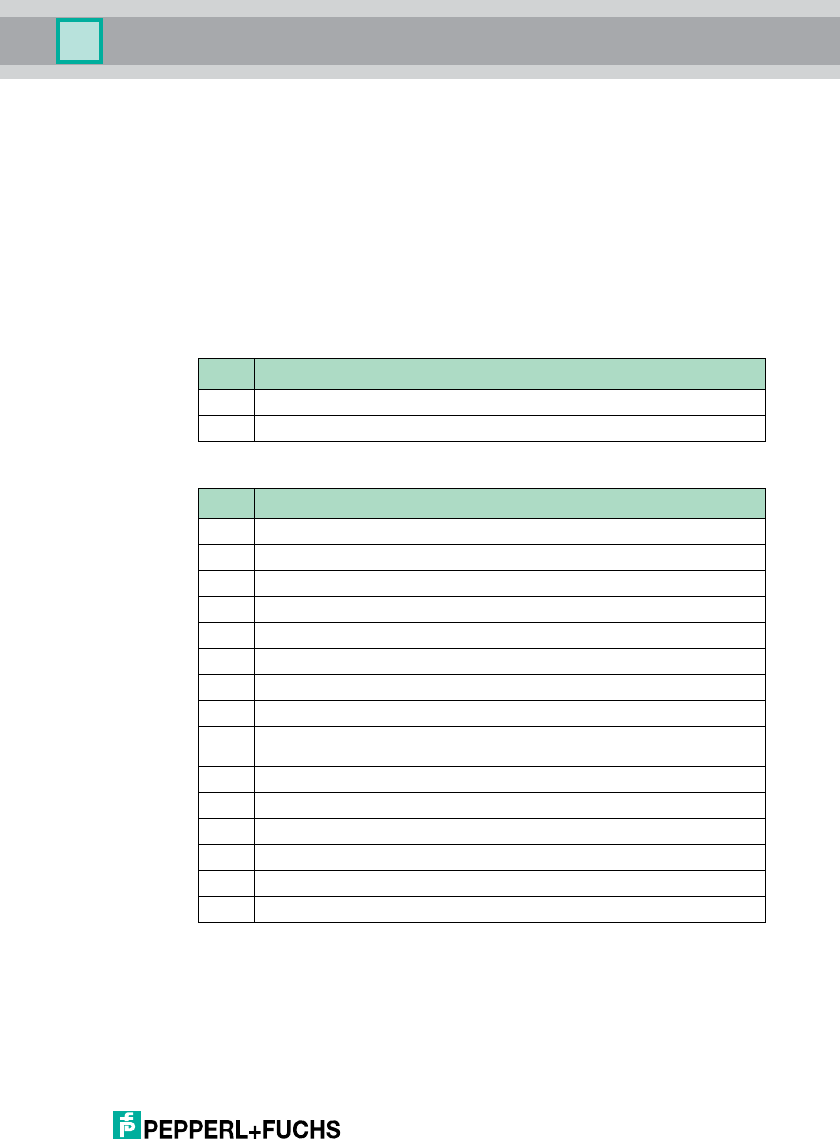
7.5 Fault/status messages
Error messages triggered by the identification system
<SystemCode>: = U
<Tagtype>: 2 ASCII characters
<Timeout>: Interface timeout; an error message is sent after this time runs out
<UII/EPC>: Unique Item Identifier, memory area of a tag in accordance with ISO
18000-6 C, in which the EPC code is stored, for example.
<WordAddr>: Word start address in the read/write tag, 4 ASCII characters, range from
‘0000h’ to ‘FFFFh’, depending on tag type.
<WordNum>: Number of words to be read or written (length of 4 bytes), 2 ASCII
characters. Range from "01" to "20", depending on tag type.
Status Meaning
0The command has been executed without error.
1The command is processing.
Status Meaning
1Reserved
2Switch-on message, reset has been executed.
3Reserved
4Incorrect or incomplete command or parameter not in the valid range.
5No data carrier in the detection range.
6Hardware error, e.g. error during self-test or read/write head defective.
7Internal device error.
8Reserved
9The parameterized data carrier type is not compatible with the connected read
head.
AThere are several transponders in the detection range (UHF).
BReserved
CReserved
DReserved
EThe internal cache is full.
FReserved

2012-09
42
IUH-F117-V1-*
Service and Maintenance
8 Service and Maintenance
The device is designed and constructed to function stable over long periods of
time. For this reason, regular cleaning or maintenance is unnecessary.

IUH-F117-V1-*
Troubleshooting
2012-09
43
9 Troubleshooting
Problem Solution
Interference from several read/write heads
in the direct vicinity
■Send the parameter CA
■Change the channel setting
■Reduce the transmitting power
Status 5 message even though
transponder in the detection area
■Check the preset transponder type (see
chapter 7.3.1),
change the transponder type to 70,
read the TID using the SF command,
you can derive the transponder type
from the TID
Status A message ■Check whether several transponders are
located in the detection area:
place the transponder in an enclosed
metal container to remove it from the
detection area
Repeat the read or write process

2012-09
44
IUH-F117-V1-*
ASCII table
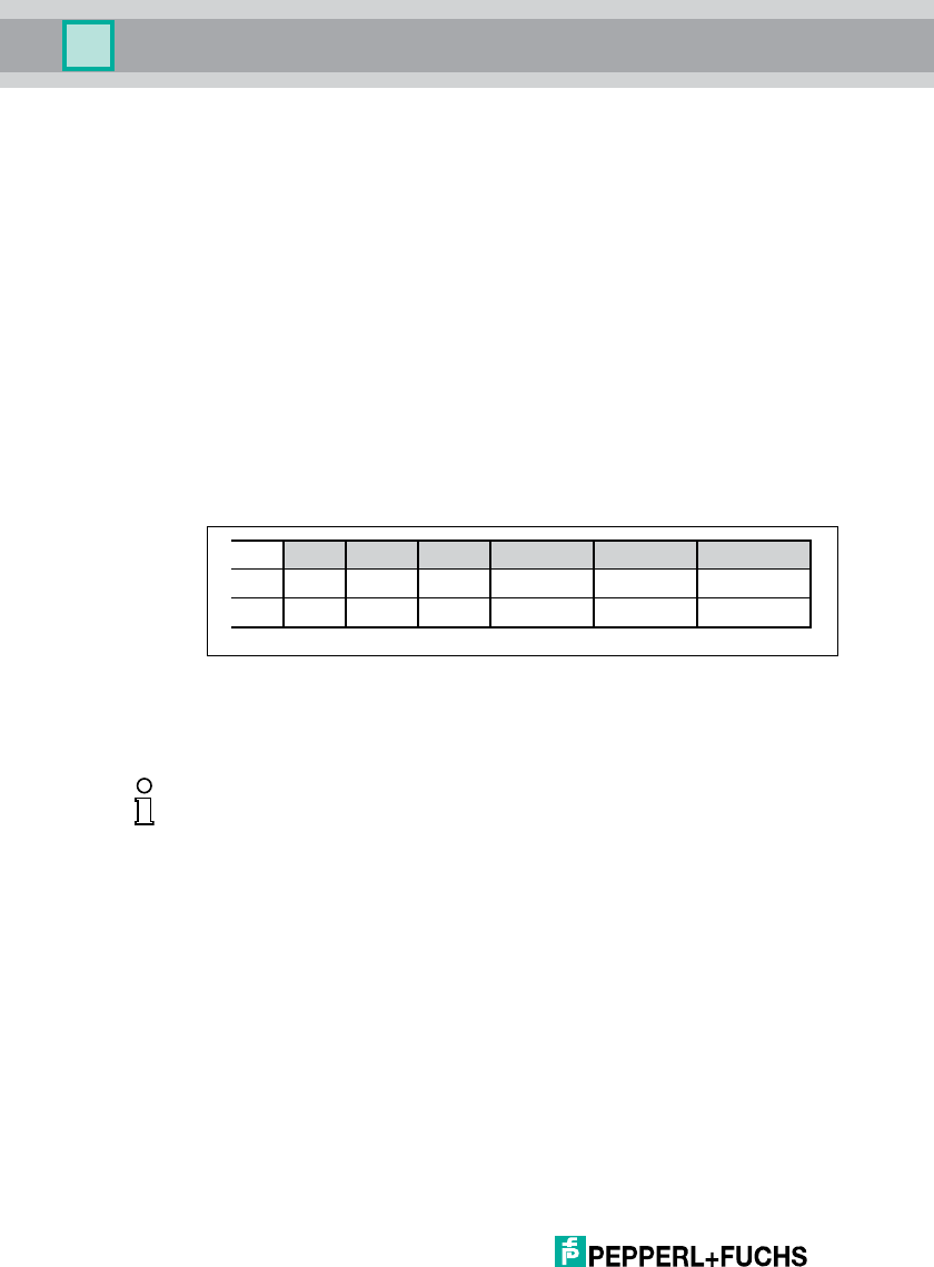
10 ASCII table
hex dec ASCII hex dec ASCII hex dec ASCII hex dec ASCII
00 0NUL 20 32 Space 40 64 @60 96 '
01 1SOH 21 33 !41 65 A61 97 a
02 2STX 22 34 "42 66 B62 98 b
03 3ETX 23 35 #43 67 C63 99 c
04 4EOT 24 36 $44 68 D64 100 d
05 5ENQ 25 37 %45 69 E65 101 e
06 6ACK 26 38 &46 70 F66 102 f
07 7BEL 27 39 '47 71 G67 103 g
08 8BS 28 40 (48 72 H68 104 h
09 9HT 29 41 )49 73 I69 105 I
0A 10 LF 2A 42 *4A 74 J6A 106 j
0B 11 VT 2B 43 +4B 75 K6B 107 k
0C 12 FF 2C 44 ,4C 76 L6C 108 l
0D 13 CR 2D 45 -4D 77 M6D 109 m
0E 14 SO 2E 46 .4E 78 N6E 110 n
0F 15 SI 2F 47 /4F 79 O6F 111 o
10 16 DLE 30 48 050 80 P70 112 p
11 17 DC1 31 49 151 81 Q71 113 q
12 18 DC2 32 50 252 82 R72 114 r
13 19 DC3 33 51 353 83 S73 115 s
14 20 DC4 34 52 454 84 T74 116 t
15 21 NAK 35 53 555 85 U75 117 u
16 22 SYN 36 54 656 86 V76 118 v
17 23 ETB 37 55 757 87 W77 119 w
18 24 CAN 38 56 858 88 X78 120 x
19 25 EM 39 57 959 89 Y79 121 y
1A 26 SUB 3A 58 :5A 90 Z7A 122 z
1B 27 ESC 3B 59 ;5B 91 [7B 123 {
1C 28 FS 3C 60 <5C 92 \7C 124 |
1D 29 GS 3D 61 =5D 93 ]7D 125 }
1E 30 RS 3E 62 >5E 94 ^7E 126 ~
1F 31 US 3F 63 ?5F 95 _7F 127 DEL
IUH-F117-V1-*
Appendix
2012-09
45
11 Appendix
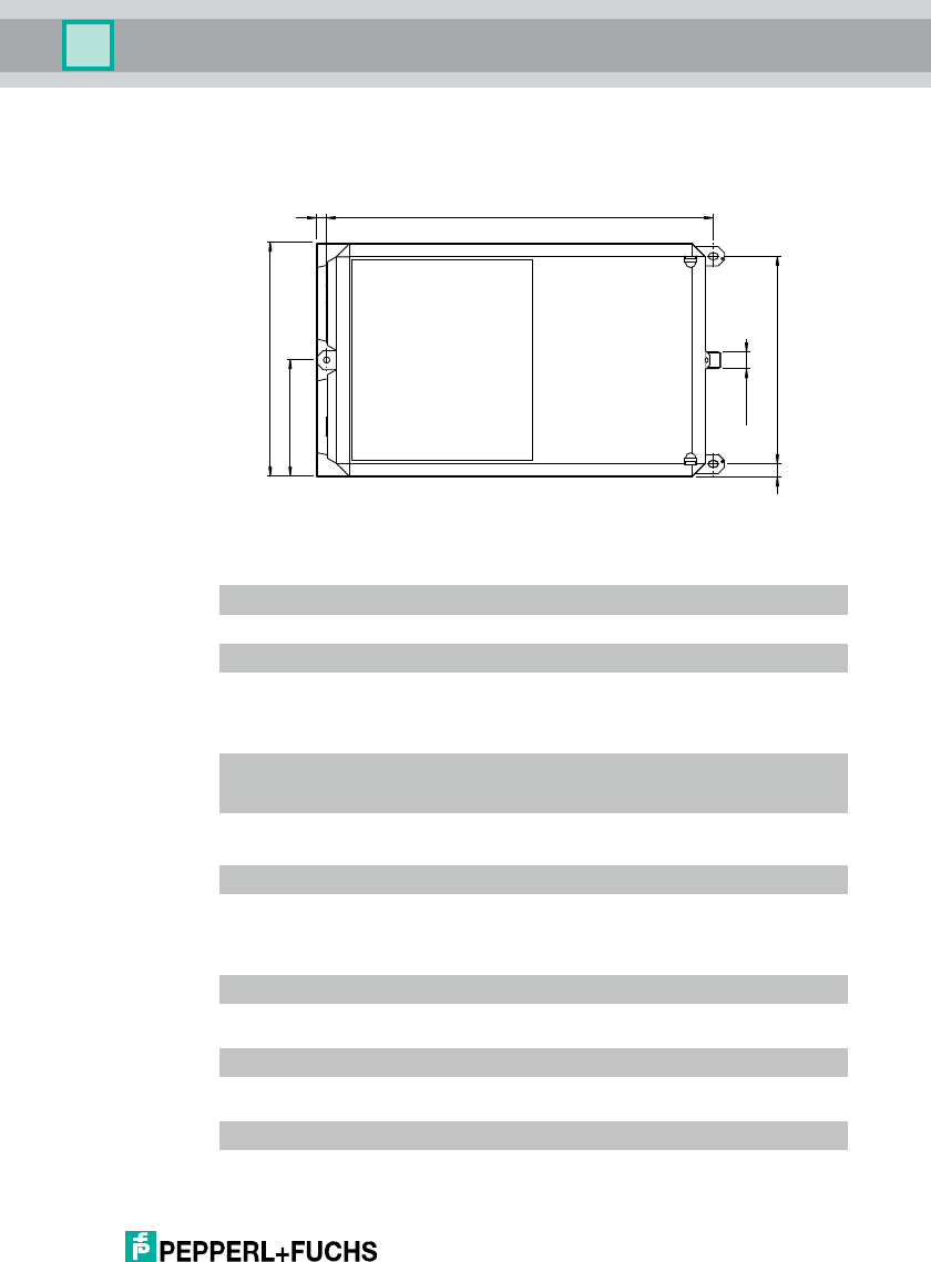
11.1 Dimensions
11.2 Technical Data
General specifications
Indicators/operating means
Electrical specifications
Compliance with standards and directives
300.58
1619
180
90
M12 x 1
Device IUH-F117-V1-EU IUH-F117-V1-US IUH-F117-V1-CN
Operating frequency 865.1 ... 867.9 MHz 902 ... 928 MHz 920.5 ... 924.5 MHz
Radiated power 2 W ERP 4 W EIRP 2 W ERP
Operating distance maximum: 6 m maximum: 6 m maximum: 6 m
LED green/yellow green: power on
green flashing: read/write attempt performed
yellow: command executed
Power consumption 30 W
Supply from the IDENTControl
Directive conformity
R&TTE Directive
1995/5/EC
EN 301489-1, EN 301489-3, EN 302208, EN 60950-1
Standard conformity
Electromagnetic
compatibility
EN 301489-1:2008 , EN 301489-3:2002
Protection degree EN 60529:2000
Standards EN 50364:2010

2012-09
46
IUH-F117-V1-*
Appendix
Ambient conditions
Mechanical specifications
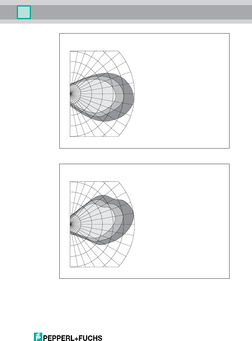
11.3 Detection Range
The maximum range of the UHF antenna IUH-F117-V1-* in open areas is 6 m.
The specified maximum working range in the industrial environment is 3 m. These
ranges depend largely on the respective tag type.
Please note the distance tables. The distance tables and additional information
on your product can be found at http://www.pepperl-fuchs.com. To do this, simply
enter the product name or model number in the search box and then click the
Search key.
Select your product from the list of search results. Click on the information you
require in the product information list, e.g., Tec h n i cal do cu m en ts .
A list of all available documents is displayed.
Measurements produced the following far field for the UHF antenna IUH-F117-V1-
*. The diagram shows the detection range for horizontal polarization under ideal
conditions. The detection range shown is an example and varies depending on
the tag types.
Ambient
temperature
-25 ... 55 °C (-13 ... 131 °F)
Storage temperature -25 ... 85 °C (-13 ... 185 °F)
Protection degree IP54
Connection M12 x 1 connector
Material
Housing aluminum / ABS
Mass approx. 3.1 kg
IUH-F117-V1-*
Appendix
2012-09
47
Figure 11.1 Horizontal detection range with horizontal polarization
Figure 11.2 Vertical detection range with horizontal polarization
Curve 1 shows the detection range under optimum operating conditions with a
transmission power of 2000 mW ERP.
Curve 2 shows the detection range under optimum operating conditions with a
transmission power of 1000 mW ERP.
Abstand [m]
Winkel [Grad]
Horizontaler Erfassungsbereich
5,0 6,0
0,0
1,0
2,0
3,0
4,0
90 80 70 60 50 40
20
10
0
-10
-20
30
-30
123
Abstand [m]
Winkel [Grad]
Vertikaler Erfassungsbereich
5,0 6,0
0,0
1,0
2,0
3,0
4,0
90 80 70 60 50 40
20
10
0
-10
-20
30
-30
123

2012-09
48
IUH-F117-V1-*
Appendix
Curve 3 shows the detection range under optimum operating conditions with a
transmission power of 500 mW ERP.
Passing Speed
The passing speed is the speed at which the tag moves through the detection
range of a read/write head. The passing speed determines the time during which
a tag is located within the detection range and therefore the time available for
transmitting data. The passing speed depends on a number of different factors.
Example:
Read/write head with the enhanced read read-only code EF command
continuously attempts to read a read-only code.
Time taken for the read-only code to be successfully read = 20 ms
Distance from the tag to the read/write head = 1.5 m for a detection range of ±30°.
The ideal distance is half the max. read distance as per the datasheet.
Therefore:
Distance covered (s) within the detection range: results from two
attempts s = 2x = 2 · 1.5 m · tan 30° = 1.73 m
Maximum tag speed:
Under industrial operating conditions, a read attempt may need to be repeated.
The time required for this repeat is allowed for when calculating a maximum
speed under real conditions. The maximum speed in this case is therefore
150 km/h.
Please consult Pepperl+Fuchs for specific data on read and write times, as well as
passing speeds.
tan 30° = x
1,5 m
v = = 86,5 m/s ≈ 300 km/h
1,73 m
20 ms
max

IUH-F117-V1-*
Appendix
2012-09
49

Subject to modifications
Copyright PEPPERL+FUCHS • Printed in Germany
www.pepperl-fuchs.com
FACTORY AUTOMATION –
SENSING YOUR NEEDS
Worldwide Headquarters
Pepperl+Fuchs GmbH
68307 Mannheim · Germany
Tel. +49 621 776-0
E-mail: info@de.pepperl-fuchs.com
USA Headquarters
Pepperl+Fuchs Inc.
Twinsburg, Ohio 44087 · USA
Tel. +1 330 4253555
E-mail: sales@us.pepperl-fuchs.com
Asia Pacific Headquarters
Pepperl+Fuchs Pte Ltd.
Company Registration No. 199003130E
Singapore 139942
Tel. +65 67799091
E-mail: sales@sg.pepperl-fuchs.com
TDOCT2077D_ENG
09/2012