Pepperl Fuchs IUH-F192-V1 UHF RFID read/write device User Manual IUH F192 V1 QSG
Pepperl + Fuchs Inc UHF RFID read/write device IUH F192 V1 QSG
Contents
- 1. user manual 4140
- 2. user manual 4881
user manual 4881
IUH-F192-V1-*
Read/Write Head for IDENTControl
FACTORY AUTOMATION
QUICK START GUIDE

With regard to the supply of products, the current issue of the following document is ap-
plicable: The General Terms of Delivery for Products and Services of the Electrical Indus-
try, published by the Central Association of the Electrical Industry (Zentralverband
Elektrotechnik und Elektroindustrie (ZVEI) e.V.) in its most recent version as well as the
supplementary clause: "Expanded reservation of proprietorship"
IUH-F192-V1-*

IUH-F192-V1-*
3
1 Introduction................................................................................. 4
1.1 Purpose of this quick start guide ....................................................... 4
1.2 Product documentation on the internet............................................. 4
1.3 Declaration of Conformity (R&TTE Directive 1995/5/EC)................. 4
1.4 FCC Information ................................................................................... 4
1.5 IC Information....................................................................................... 5
1.6 UL Information...................................................................................... 5
1.7 Additional country-specific approvals............................................... 5
2 Product Description ................................................................... 6
2.1 General Functions and Features......................................................... 6
2.2 Indicators and Operating Elements ................................................... 6
2.3 Connection ........................................................................................... 6
2.4 Scope of Delivery................................................................................. 7
2.5 Accessories .......................................................................................... 7
2.5.1 IDENTControl .................................................................................... 7
2.5.2 Read/Write Tags ................................................................................ 8
2.5.3 Connection cable for R/W heads and trigger sensors ........................ 8
2.5.4 Cable connectors for the power supply .............................................. 8
2.5.5 Installation accessories...................................................................... 8
3 Installation................................................................................... 9
3.1 Storage and transport.......................................................................... 9
3.2 Unpacking............................................................................................. 9
3.3 Mounting ............................................................................................... 9
3.3.1 Room Orientation............................................................................. 10
3.3.2 Minimum Distances ......................................................................... 10
3.3.3 Polarization ...................................................................................... 10
3.4 Connection ......................................................................................... 11
3.5 EMC Concept...................................................................................... 12
4 Commissioning......................................................................... 13
4.1 Initial Commissioning........................................................................ 13
4.2 Device Settings .................................................................................. 14
4.3 Operation via the Command Interface............................................. 15

2015-09
4
IUH-F192-V1-*
Introduction
1 Introduction
1.1 Purpose of this quick start guide
This quick start guide contains basic instructions for operating the device. However, the manual
takes priority over the quick start guide.
1.2 Product documentation on the internet
You can view all the relevant documentation and additional information on your product at
http://www.pepperl-fuchs.com. Simply enter the product name or model number in the
Product/Key word search box and click Search.
Select your product from the list of search results. Click on the information you require in the
product information list, e.g., Technical documents.
A list of all available documents is displayed.
1.3 Declaration of Conformity (R&TTE Directive 1995/5/EC)
This product was developed and manufactured under observance of the applicable European
standards and guidelines.
The product manufacturer, Pepperl+Fuchs GmbH, 68307 Mannheim, has a certified quality
assurance system that conforms to ISO 9001.
1.4 FCC Information
Note:
This equipment has been tested and found to comply with the limits for a Class A digital device,
pursuant to part 15 of the FCC Rules. These limits are designed to provide reasonable
protection against harmful interference when the equipment is operated in a commercial
environment. This equipment generates, uses, and can radiate radio frequency energy and, if
not installed and used in accordance with the instruction manual, may cause harmful
interference to radio communications. Operation of this equipment in a residential area is likely
to cause harmful interference in which case the user will be required to correct the interference
at his own expense.
Note!
A Declaration of Conformity can be requested from the manufacturer or downloaded from
www.pepperl-fuchs.com.
ISO9001
FCC ID: IREIUH-F192-V1
This device complies with Part 15 of the FCC Rules. Operation is subject to the following two
conditions:
1. This device may not cause harmful interference, and
2. This device must accept any interference received, including interference that may cause
undesired operation.
Attention:
Changes or modifications not expressly approved by the party responsible for compliance
could void the user's authority to operate the equipment.

IUH-F192-V1-*
Introduction
2015-09
5
FCC Notice
To comply with FCC part 15 rules in the United States, the system must be professionally
installed to ensure compliance with the Part 15 certification. It is the responsibility of the
operator and professional installer to ensure that only certified systems are deployed in the
United States. The use of the system in any other combination (such as co-located antennas
transmitting the same information) is expressly forbidden.
FCC Exposure Information
To comply with FCC RF exposure compliance requirements, the antennas used for this
transmitter must be installed to provide a separation distance of at least 30 cm from all persons
and must not be co-located or operated in conjunction with any other antenna or transmitter.
1.5 IC Information
IC Exposure Information
To comply with IC RF exposure compliance requirements, the antennas used for this
transmitter must be installed to provide a separation distance of at least 30 cm from all persons
and must not be co-located or operated in conjunction with any other antenna or transmitter.
1.6 UL Information
Technical Data and Environmental Conditions
This device is for indoor use only.
This device may be operated in altitudes up to 2000 m.
The ambient temperature range is from -25 °C to +50 °C for continuous transmission mode, or
-25 °C to +70 °C for operation with non-transmission periods.
The maximum relative humidity is 80 % for temperatures up to 31 °C decreasing linearly to 50
% relative humidity at 40 °C.
Nominal power supply voltage is 24 V
DC
. For the intended use this read/write head
has to be connected to Pepperl+Fuchs IDENTControl control interfaces using a shielded
connection cable. The IDENTControl supplies the read/write head with 20 ... 30 V
DC
, Protective
Extra Low Voltage (PELV).
Protection class IP67 is not included in the UL approval. The protection class is tested by
Pepperl + Fuchs GmbH.
1.7 Additional country-specific approvals
For all current approvals see the data sheet of your read / write head under www.pepperl-
fuchs.com.
This device complies with Industry Canada licence-exempt RSS standard(s) and with part 15
of the FCC Rules. Operation is subject to the following two conditions:
1. this device may not cause interference, and
2. this device must accept any interference, including interference that may cause undesired
operation of the device.
Le présent appareil est conforme aux CNR d'Industrie Canada applicables aux appareils
radio exempts de licence. L'exploitation est autorisée aux deux conditions suivantes :
1. l'appareil ne doit pas produire de brouillage, et
2. l'utilisateur de l'appareil doit accepter tout brouillage radioélectrique subi, même si le brouil-
lage est susceptible d'en compromettre le fonctionnement.

2015-09
6
IUH-F192-V1-*
Product Description
2 Product Description
2.1 General Functions and Features
Functions
The read/write head was developed for reading and writing passive read/write tags with an
ultra-high operating frequency.
Detection Range
The detection range is typically 4 meters. Tags that comply with EPC Gen 2 (ISO/IEC 18000-
63) are supported.
Maximum Frequency Range
The IUH-F192-V1-FR1 read/write head can be operated in the frequency range from 865 MHz
to 868 MHz. The IUH-F192-V1-FR2 read/write head can be operated in the frequency range
from 902 MHz to 928 MHz.
Features
The read/write head has the following features:
■
2 x 3 function indicator LEDs
■
Industrial housing
■
Bulk detection
■
Connects to the IDENTControl via connector V1 (M12 x 1)
■
Protected against electrostatic discharge
Integrated antenna
The IUH-F192-V1-FR1 and IUH-F192-V1-FR2 read/write heads have a linear dual-polarized
antenna. The read/write heads can transmit and receive waves with horizontal and vertical
polarization.
2.2 Indicators and Operating Elements
The IUH-F192-V1-* read/write head has 2 x 3 LEDs, which are green/blue/yellow. The various
indicators denote:
■
Green LED:
Continuously on - Power on
Flashing - Region code must be set. See chapter 4.1.
■
Yellow LED: Read/write operation successful
■
Blue LED: Transmission mode
2.3 Connection
The read/write head is connected to the IDENTControl control interface via the M12 x 1
connector.
Figure 2.1
Shield
do not connect
+
A
-
B
1
2
3
5
4
1
4
5
2
3
IUH-F192-V1-*
Product Description
2015-09
7
Ground connection
The ground connection of the read / write head is on the right side when the cable outlet faces
downward. Connect the protective earth conductor to the casing the with a crimp connector. To
ensure proper grounding, you must install the lock washer between the crimp and the housing.
Use a conductor cross section of at least 4 mm
2
for the protective earth conductor.
Tighten the lock screw with a torque of 1.6 Nm ±0,4 Nm
2.4 Scope of Delivery
■
Read/write head
■
Quick start guide
2.5 Accessories
2.5.1 IDENTControl
The read/write head can be connected to Pepperl+Fuchs IDENTControl control interfaces.
1Housing
2Serrated lock washer
3Crimp connector
4Lock screw
1 2 43
Interface Designation
4 read/write heads:
Ethernet IC-KP-B17-AIDA1
2 read/write heads:
PROFIBUS IC-KP2-2HB6-V15B
Ethernet IC-KP2-2HB17-2V1D
EtherCAT IC-KP2-2HB21-2V1D
Serial IC-KP2-2HRX-2V1
1 read/write head:
PROFIBUS IC-KP2-1HB6-V15B
IC-KP2-1HB6-2V15B
Ethernet IC-KP2-1HB17-2V1D
Serial IC-KP2-1HRX-2V1
Table 2.1

2015-09
8
IUH-F192-V1-*
Product Description
2.5.2 Read/Write Tags
2.5.3 Connection cable for R/W heads and trigger sensors
Compatible connection cables with shielding are available for connecting the R/W heads and
trigger sensors.
2.5.4 Cable connectors for the power supply
Compatible M12 sockets with an open cable end for connecting the IDENTControl to a power
supply are available in different lengths.
2.5.5 Installation accessories
Two different mounting brackets are available to mount the read/write head on a wall or pole.
Type Designation
EPC Gen 2 (ISO/IEC 18000-63) IUC72-F152-M-FR1
IUC72-F152-M-FR2
IUC76-50-FR1
IUC76-50-FR2
IUC76-F157-M-FR1
IUC76-F157-M-FR2
IUC76-F203-M-FR1
IUC76-F203-M-FR2
IUC76-C8-T14-GBL
IUC77-F151-M-GBL
IUC77-25L100-GBL
IUC77-25L110-GBL
Table 2.2
Accessories Description
2 m long (straight female, angled male) V1-G-2M-PUR-ABG-V1-W
5 m long (straight female, angled male) V1-G-5M-PUR-ABG-V1-W
10 m long (straight female, angled male) V1-G-10M-PUR-ABG-V1-W
20 m long (straight female, angled male) V1-G-20M-PUR-ABG-V1-W
Field attachable female connector, straight, shielded V1-G-ABG-PG9
Field attachable male connector, straight, shielded V1S-G-ABG-PG9
Field attachable female connector, angled, shielded V1-W-ABG-PG9
Field attachable male connector, angled, shielded V1S-W-ABG-PG9
Dummy plug M12x1 VAZ-V1-B3
Accessories Designation
Length 2 m (straight socket) V1-G-2M-PUR
Length 5 m (straight socket) V1-G-5M-PUR
Length 10 m (straight socket) V1-G-10M-PUR
Accessories Designation
Mounting bracket for wall attachment IUZ-MH10
Mounting bracket for pipe installation (pipe with
maximum diameter of 40 mm)
IUZ-MH11
IUH-F192-V1-*
Installation
2015-09
9
3 Installation
3.1 Storage and transport
For storage and transport purposes, package the unit using shockproof packaging material
and protect it against moisture. The best method of protection is to package the unit using the
original packaging. Furthermore, ensure that the ambient conditions are within allowable range.
3.2 Unpacking
Check the product for damage while unpacking. In the event of damage to the product, inform
the post office or parcel service and notify the supplier.
Check the package contents against your purchase order and the shipping documents for:
■
Delivery quantity
■
Device type and version in accordance with the type label
■
Any accessories ordered
Retain the original packaging in case you have to store or ship the device again at a later date.
Should you have any questions, please contact Pepperl+Fuchs.
3.3 Mounting
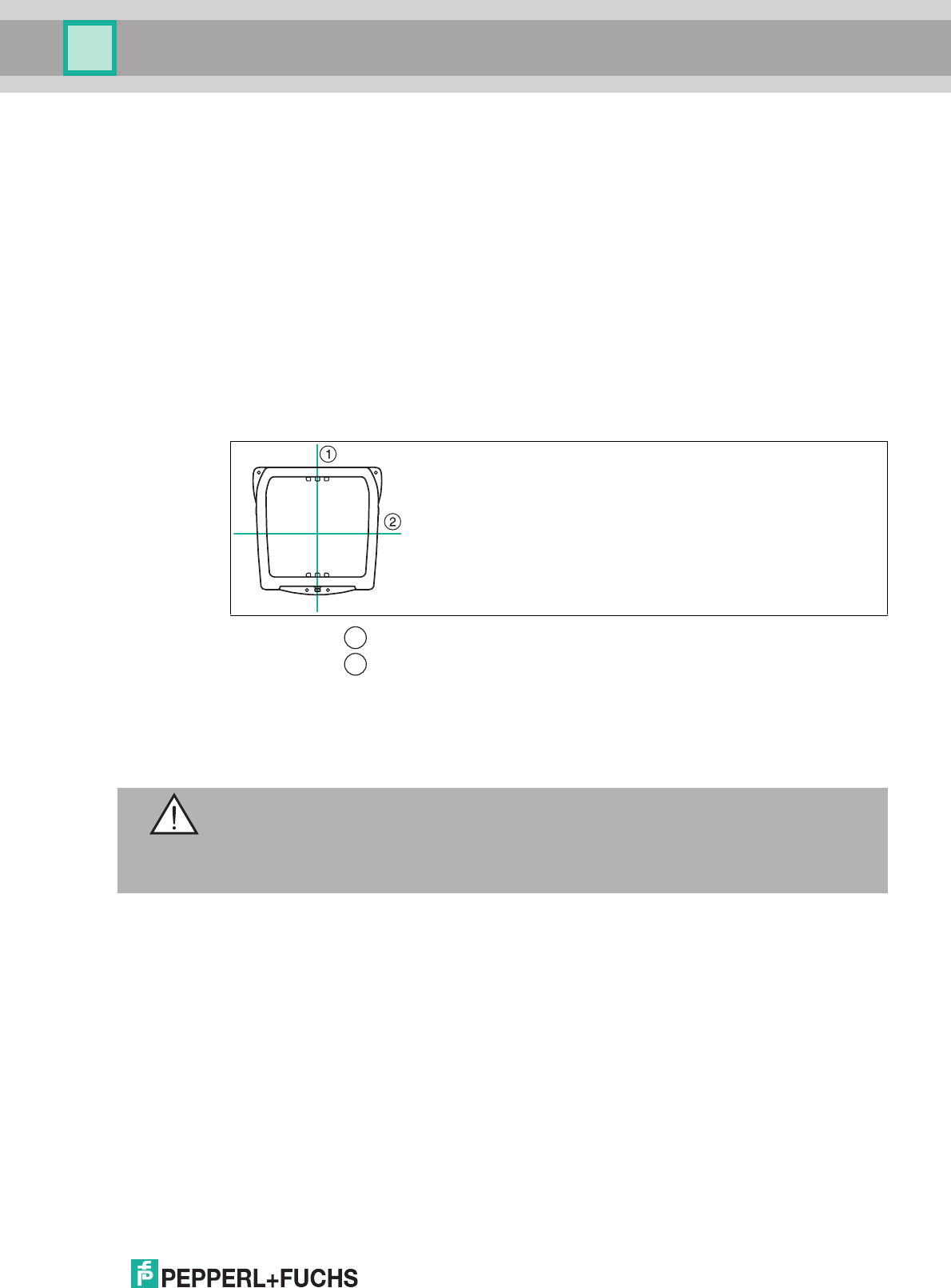
The read/write head is intended for wall mounting or mounting on brackets in internal areas.
Please mount the read/write head using only the holes provided in the housing. The preferred
mounting direction is with the cable connection facing vertically downwards.
To attach the read/write head, use four screws with a diameter of 6 mm, as well as mounting
materials that are suitable for the type of mounting surface. The tightening torque of the screws
depends on the type of mounting.
Figure 3.1
Note!
Do not lay the connection cable in the main beam direction of the antenna.
Caution!
Mounting the read/write head
Make sure that the read/write head is firmly attached to the mounting surface.
Mounting the Read/Write Head
2015-09
10
IUH-F192-V1-*
Installation
3.3.1 Room Orientation
The alignment of the read/write tag antennae in relation to the antennae of the read/write head
influences the detection range of the system. Make sure the antennae are aligned parallel to
each other.
3.3.2 Minimum Distances
When positioning the read/write head, please observe the minimum distances. The lateral
distance between the read/write head and metals or liquids should be at least 50 cm. The
distance between the read/write head and the ground should be at least 50 cm.
During simultaneous operation of several read/write heads, only one read/write head may ever
communicate with a tag at any given time. When arranging the read/write heads, make sure
that the measurement ranges do not overlap. You can enlarge or reduce the size of the
measurement range by changing the transmitting power. Determine the measurement range of
each read/write head at the mounting location.
If you want to transmit with just one read/write head at any given time, use the multiplex mode
of the IDENTControl control interface. Multiplex operating mode allows chronologically
exclusive access to tags, and prevents mutual interference from read/write heads. For a precise
description, see the manual for your control interface.
3.3.3 Polarization
The polarization of the electromagnetic wave emitted by an antenna depends on the
electromagnetic field component and the position of the antenna. Polarization can be either
linear or circular. To achieve the maximum detection range for a UHF system, the polarization
of the read/write head must match the polarization of the tag. Refer to the relevant data sheet to
find the polarization of the tag.
Optimum alignment of the tag
■
Good communication between the read/write head
and tag
Poor alignment of the tag
■
Insufficient communication between the read/write
head and tag
Read/write head
Tag
1
2
Note!
During mounting, take into account how the read/write heads may cause interference with each
other. The further the transmission channels of the read/write heads are from each other, the
lower the risk of interference.
IUH-F192-V1-*
Installation
2015-09
11
■
Linear polarization: When an electromagnetic wave has linear polarization, the direction
of the vector of the electromagnetic field component is constant. Linear polarization can
be either vertical or horizontal. This characteristic depends on the position of the antenna.
■
Circular polarization: When an electromagnetic wave has circular polarization, the vector
of the electromagnetic field component rotates around an axis parallel to the direction of
emission. The rotation of the antenna around the transmission axis has no effect.
The integrated antenna of the IUH-F192-V1-* read/write head has dual linear polarization. The
read/write head operates in combined mode by default. In combined mode, both horizontal and
vertical polarization are used for each read/write access. This increases the reading reliability
of tags with an unknown location in the room.
If the orientation of the tags is known, you can optimize the access time by setting a fixed
polarization. To do this, you can switch the polarization to horizontally linear polarization or
vertically linear polarization via the IDENTControl control interface software. The linear
polarization plane refers to the preferred mounting direction with the cable connection mounted
vertically downwards.
Figure 3.2 = Vertical polarization plane
= Horizontal polarization plane
3.4 Connection
Connect the read/write head to the IDENTControl control interface using a shielded connection
cable (see chapter 2.5.3). Ensure that the shield is end-to-end to avoid EMC interference. (see
chapter 3.5)
After connecting the supply voltage to the control interface, the POWER LED lights up green on
the device. If the LED does not light up on the device, the power supply is not connected
correctly.
1
2
Warning!
Incorrect electrical connection
Damage to the device or plant caused by incorrect electrical connection.
Check all connections in the plant before commissioning the device.
2015-09
12
IUH-F192-V1-*
Installation
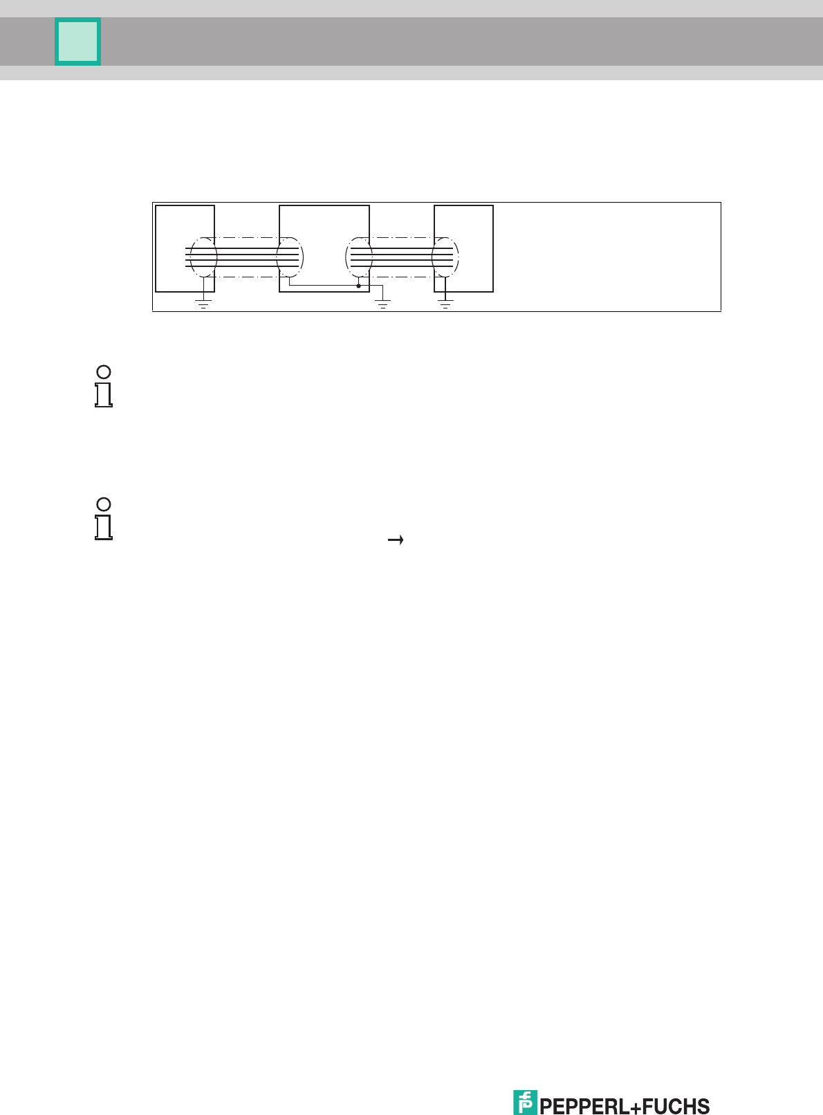
3.5 EMC Concept
The outstanding noise immunity of the IDENTControl against emission and immission is based
on its consistent shielding design, which uses the principle of the Faraday cage. Interference is
caught in the shield and safely diverted via the ground connections.
The cable shielding is used to discharge electromagnetic interference. When shielding a cable,
you must connect both sides of the shield to ground with low resistance and low inductance.
write head ControlIDENTControl INTERBUS
Note!
If cables with double shields are used, e.g. wire mesh and metalized foil, the both shields must
be connected together, with low resistance, at the ends when making up the cable.
Power supply cables are the source of much interference, e.g. from the supply lines of 3-phase
electric motors. For this reason, the parallel laying of power supply cables with data and signal
cables should be avoided, particularly in the same cable duct.
Note!
The circuit ground is conductively connected to the housing of the write/read head and to the
protective ground. (Connection image see Figure 2.1 on page 6)

IUH-F192-V1-*
Commissioning
2015-09
13
4 Commissioning
4.1 Initial Commissioning
All IUH-F192-V1-* read/write heads operate within their maximum frequency range from
865 MHz to 868 MHz, or from 902 MHz to 928 MHz, with the appropriate settings for the
relevant country. This enables the following parameters to be set according to the applicable
regulations for the relevant country:
■
The maximum occupied bandwidth
■
The channel bandwidth
■
The channel plan used
■
The frequency access method
■
The maximum power setting
Country identifiers for IUH-F192-V1-FR1
(The currently valid transmission licenses can be found in the data sheet at pepperl-fuchs.com)
Note!
Transmission License
A country-specific transmission license is required to operate the read/write head. In the
European Union and Turkey, the manufacturer's EU declaration of conformity constitutes an
adequate license. A currently valid transmission license may not exist for all countries of use
listed in this chapter, as transmission licenses are temporary in some countries. All currently
valid transmission licenses can be found in the data sheet for the respective read/write head at
www.pepperl-fuchs.com
Note!
Country Identifier
The IUH-F192-V1-FR* read/write head has no valid country identifier by default. This status is
indicated by the flashing green LED. In this state, the read/write head will accept only the
command for setting the relevant country identifier. Once you have parameterized a valid
country identifier, you can begin using the read/write head.
The IUH-F192-V1-FR2-02 is supplied ex-works with the country identifier "02" for the USA,
Canada, and Mexico. Due to legal regulations, you cannot change this country identifier in the
IUH-F192-V1-FR2-02.
Note!
The country identifier set is saved in the read/write head as non-volatile. The country identifier
setting is not affected by a reset to the factory settings. It can be overwritten with another valid
country identifier at any time.
Country
Identifier
Occupied Frequency Bandwidth
Frequency Access Method Country or Region
01 865.6 MHz – 867.6 MHz
Programmable frequency list
EU and other countries subject to EN
302208
04 865.0 MHz – 867.0 MHz
Programmable frequency list
India
05 866.0 MHz – 868.0 MHz
Programmable frequency list
Singapore, Vietnam
06 866.0 MHz – 867.6 MHz
Programmable frequency list
Russia
2015-09
14
IUH-F192-V1-*
Commissioning
Country identifiers for IUH-F192-V1-FR2
(The currently valid transmission licenses can be found in the data sheet at pepperl-fuchs.com)
The list of country identifiers is extended from time to time. For the most current list of country
identifiers and the technical details of the regional settings, refer to the manual on
www.pepperl-fuchs.com.
For an example of reading and writing the country identifier, see chapter 4.2.
4.2 Device Settings
Before commissioning the read/write head, you need to configure the control interface. To do
so, read the "Commissioning" chapter of the manual for your control interface.
Configure the read/write heads with the described system commands. For a parameterization
example, see see chapter 4.3.
Country
Identifier
Occupied Frequency Bandwidth
Frequency Access Method Country or Region
02 902 MHz – 928 MHz
Frequency hopping spread spectrum
USA
Canada
Mexico
Argentina
Colombia
03 920 MHz – 925 MHz
Frequency hopping spread spectrum
China
07 915 MHz – 928 MHz
Frequency hopping spread spectrum
Brazil
08 916.7 MHz – 920.5 MHz
Programmable frequency list
Japan
09 917.2 MHz – 920.4 MHz
Frequency hopping spread spectrum
South Korea
10 920 MHz – 926 MHz
Frequency hopping spread spectrum
Australia
11 921.5 MHz – 928 MHz
Frequency hopping spread spectrum
New Zealand
12 920 MHz – 925 MHz
Frequency hopping spread spectrum
Hong Kong
Thailand
13 919 MHz – 923 MHz
Frequency hopping spread spectrum
Malaysia
14 920 MHz – 925 MHz
Frequency hopping spread spectrum
Singapore
Vietnam
Warning!
Device not configured or configured incorrectly
Configure the device prior to commissioning. A device that has not been configured or
configured incorrectly may lead to faults in the plant.
Caution!
Uncontrolled triggered processes
Before commissioning the device, make sure that all processes are running smoothly;
otherwise damage may occur in the plant.
IUH-F192-V1-*
Commissioning
2015-09
15
4.3 Operation via the Command Interface
This section shows you how to operate the read/write head using an IDENTControl control
interface with serial interface. The commissioning procedure described relates to the RS-232
interface and involves a PC. The examples include the syntax for coding the commands and
parameters via the Ethernet TCP/IP and PROFIBUS/PROFINET interfaces. Further details
about these codes and the factory settings for your IDENTControl control interface can be
found in the manual.
Example:
In the examples below, the read/write head is connected to channel 1 of the control interface.
The outputs follow the multiframe protocol, .
Reading the Country Identifier
Read Parameter RC
Use the read parameter RC command to read out the read/write head's country identifier:
The country identifier set on the read/write head is 01, where 01 corresponds to the country
identifier for the European Union.
Writing the Country Identifier
Write Parameter RC
Use the write parameter RC command to change the country identifier on the read/write head
to 04 (= India).
Reading Tags
Enhanced Read Read-Only Code
Send the enhanced read read-only code command to the read/write head. The "RF ON" LED
on the read/write head lights up blue.
Serial Ethernet PROFIBUS/PROFINET
Command: RP1URC.00.00 .00.0A.BE.03.00.55.52.43.
00.00
.BE.03.00.55.52.43.00.00
Confirmation: - .00.06.BE.03.FF.3E .BE.03.FF.3E
Response: .30.31.00.01 .00.0A.BE.03.00.3F.00.02.
00.01
.BE.03.00.3F.00.02.00.01
Table 4.1 Read Parameter RC
Serial Ethernet PROFIBUS/PROFINET
Command: WP1URC.00.02.
00.04
.00.0C.BF.03.00.55.52.43.
00.02.00.04
.BF.03.00.55.52.43.00.02.
00.04
Confirmation: - .00.06.BF.03.FF.11 .BF.03.FF.11
Response: .30.31 .00.06.BF.03.00.12 .BF.03.00.12
Table 4.2 Write Parameter RC
Serial Ethernet PROFIBUS/PROFINET
Command: EF1 .00.04.1D.03 .1D.03
Confirmation: - .00.06.1D.03.FF.0B .1D.03.FF.0B
Response: .35.31 .00.06.1D.03.05.0C .1D.03.05.0C
Table 4.3 Enhanced read read-only code, no tag in the measurement range
2015-09
16
IUH-F192-V1-*
Commissioning
Move a tag into the read/write head's measurement range. When the tag has been detected
and the read-only code has been read out, the "READ / WRITE" LED on the read/write head
lights up yellow. The read-only code is displayed in the terminal program.
Describing Tags
Single Write Special Read-Only Code
Send the single write special read-only code command to the read/write head while a tag is in
the measurement range.
Single Read Special Read-Only Code
As confirmation, read out the read-only code of the tag within the read/write head's
measurement range via the single read special read-only code command.
Serial Ethernet PROFIBUS/PROFINET
Response: .30.31.00.0E.30.
00.30.14.F7.33.7
C.00.1F.00.00.00
.00.01.00.08.E2.
00.60.03.14.42.D
6.D1
.00.20.1D.03.00.0D.00.0E.
30.00.30.14.F7.33.7C.00.1
F.00.00.00.00.01.00.08.E2
.00.60.03.14.42.D6.D1
.1D.03.00.0D.00.0E.30.00.
30.14.F7.33.7C.00.1F.00.0
0.00.00.01.00.08.E2.00.60
.03.14.42.D6.D1
Table 4.4 Enhanced read read-only code, tag is entering the measurement range
Serial Ethernet PROFIBUS/PROFINET
Command: SP1E.30.00.30.1
4.F7.33.7C.00.1F
.00.00.03.1C.6E
.00.14.0D.E3.00.00.30.00.
30.14.F7.33.7C.00.1F.00.0
0.03.1C.6E
.0D.E3.00.00.30.00.30.14.
F7.33.7C.00.1F.00.00.03.1
C.6E
Confirmation: - .00.06.0D.E3.FF.2D .0D.E3.FF.2D
Response: .30.31.00.0E.30.
00.30.14.F7.33.7
C.00.1F.00.00.03
.1C.6E
.46.31.30.30.30.3
1
.00.16.0D.03.00.2E.00.0E.
30.00.30.14.F7.33.7C.00.1
F.00.00.03.1C.6E
.00.0A.0D.03.0F.2F.30.30.
30.31
0D.03.00.2E.00.0E.30.00.
30.14.F7.33.7C.00.1F.00.0
0.03.1C.6E
.0D.03.0F.2F.30.30.30.31
Serial Ethernet PROFIBUS/PROFINET
Command: SS10 .00.04.0A.02 .0A.02
Confirmation: - .00.06.0A.02.FF.30 .0A.02.FF.30
Response: .30.31.00.0E.30.
00.30.14.F7.33.7
C.00.1F.00.00.03
.1C.6E
.46.31.30.30.30.3
1
.00.16.0A.02.00.31.00.0E.
30.00.30.14.F7.33.7C.00.1
F.00.00.03.1C.6E
.00.0A.0A.02.0F.32.30.30.
30.31
.0A.02.00.31.00.0E.30.00.
30.14.F7.33.7C.00.1F.00.0
0.03.1C.6E
.0A.02.0F.32.30.30.30.31
IUH-F192-V1-*
Commissioning
2015-09
17
Parameterizing the Read/Write Head
Requesting and Setting the Transmission Power
Read out the read/write head's transmission power with the read parameter PT command:
The read/write head's set transmitting power is 50 mW (32
hex
corresponding to 50
dec
).
Change the transmitting power of the read/write head to 100 mW (100
dec
corresponding to
64
hex
) via the write parameter PT command:
Serial Ethernet PROFIBUS/PROFINET
Command: RP1UPT.00.00 .00.0A.BE.03.00.55.50.54.
00.00
.BE.03.00.55.50.54.00.00
Confirmation: - .00.06.BE.03.FF.33 .BE.03.FF.33
Response: .30.31.00.32 .00.0A.BE.03.00.34.00.02.
00.32
.BE.03.00.34.00.02.00.32
Serial Ethernet PROFIBUS/PROFINET
Command: WP1UPT.00.02.0
0.64
.00.0C.BF.03.00.55.50.54.
00.02.00.64
.BF.03.00.55.50.54.04.00.
02.00.64
Confirmation: - .00.06.BF.03.FF.35 .BF.03.FF.35
Response: .30.31 .00.06.BF.03.00.36 .BF.03.00.36

Subject to modifications
Copyright PEPPERL+FUCHS • Printed in Germany
www.pepperl-fuchs.com
FACTORY AUTOMATION –
SENSING YOUR NEEDS
Worldwide Headquarters
Pepperl+Fuchs GmbH
68307 Mannheim · Germany
Tel. +49 621 776-0
E-mail: info@de.pepperl-fuchs.com
USA Headquarters
Pepperl+Fuchs Inc.
Twinsburg, Ohio 44087 · USA
Tel. +1 330 4253555
E-mail: sales@us.pepperl-fuchs.com
Asia Pacific Headquarters
Pepperl+Fuchs Pte Ltd.
Company Registration No. 199003130E
Singapore 139942
Tel. +65 67799091
E-mail: sales@sg.pepperl-fuchs.com
/ DOCT-4881
09/2015