PerComm 1005 Reflex Telemetry Device, OMNIDATA User Manual Updated
PerComm Inc Reflex Telemetry Device, OMNIDATA Updated
PerComm >
Contents
- 1. Usr Manual
- 2. Updated user manual
Updated user manual

Document Number: 9400.01484-USG01, Revision: 1.6, December 2, 2002;
User's Guide
for the
PerComm OMNIDATA
Telemetry Device - PT1005A
(DRAFT)
Copyright 2002, PerComm, Inc.
All rights reserved.

Document Number: 9400.01484-USG01 Revision 1.6 12/2/2002
Document Change Record
July 18, 2002 – December 02, 2002
• Version 1.0 – 1.6
• Preliminary (draft) revisions.
12/2/02 User's Guide for the PerComm OMNIDATA Telemetry Device - PT1005A (DRAFT)
ii

Document Number: 9400.01484-USG01 Revision 1.6 12/2/2002
Table of Contents
1 INTRODUCTION ............................................................................................................................................1
1.1 Document Identification............................................................................................................................1
1.2 Document Overview ..................................................................................................................................1
1.3 Contact Information ...................................................................................................................................1
1.4 Copyrights and Trademarks .....................................................................................................................1
1.5 Safety and Limitations ...............................................................................................................................2
1.6 RF Exposure Information ..........................................................................................................................2
1.7 References....................................................................................................................................................3
2 OMNIDATA OVERVIEW..............................................................................................................................4
2.1 Introduction.................................................................................................................................................4
2.2 Physical Features ........................................................................................................................................4
2.3 Over-The-Air Interface...............................................................................................................................5
2.4 ReFLEX 2.7.1.1 Protocol Stack................................................................................................................... 5
2.5 Host Interface ..............................................................................................................................................5
2.6 FLEXsuite Encoder .....................................................................................................................................5
2.7 Configurable Database...............................................................................................................................5
2.8 Embedded Software ...................................................................................................................................6
2.9 Power Input.................................................................................................................................................6
3 SPECIFICATIONS ...........................................................................................................................................7
3.1 Introduction.................................................................................................................................................7
3.2 Product Specification .................................................................................................................................7
3.3 Connector Specifications ...........................................................................................................................8
3.4 Power Supply Requirements ....................................................................................................................9
3.5 Mechanical Specifications..........................................................................................................................9
4 INSTALLATION AND OPERATION .......................................................................................................11
4.1 Introduction...............................................................................................................................................11
4.2 Installation Setting....................................................................................................................................11
4.3 Installation Procedure..............................................................................................................................11
4.4 Power-On Procedure................................................................................................................................12
4.5 External Antenna Impedance .................................................................................................................13
12/2/02 User's Guide for the PerComm OMNIDATA Telemetry Device - PT1005A (DRAFT)
iii

Document Number: 9400.01484-USG01 Revision 1.6 12/2/2002
1 INTRODUCTION
1.1 Document Identification
“User's Guide for the PerComm OMNIDATA Telemetry Device - PT1005A (DRAFT)”,
Document Number 9400.01484-USG01.
1.2 Document Overview
This document is intended for a technical audience installing or operating the PerComm
OMNIDATA Telemetry Device (model number PT1005A).
This document is organized as follows:
• Chapter 1 provides an overview of this User’s Guide.
• Chapter 2 provides an overview of the OMNIDATA device.
• Chapter 3 provides the technical specifications of the OMNIDATA device.
• Chapter 4 provides procedures and guidelines for the installation and operation
of the OMNIDATA device.
This document has been carefully reviewed for accuracy. However, no responsibility is
assumed for any inaccuracies. The information in this document and the products
described in this document are subject to change at any time and from time to time
without notice.
1.3 Contact Information
Any questions or comments regarding this manual or the PerComm OMNIDATA
Telemetry Device can be addressed to one of the following:
PerComm Customer Service
Phone: 888-PERCOMM
Phone: 781-860-7700
Email: CS@Percomm.com
PerComm Technical Support
Phone: 866-619-4992
Email: Tech@Percomm.com
PerComm Web Site
http://www.percomm.com/contact
1.4 Copyrights and Trademarks
This document and other referenced PerComm documents are PerComm copyrighted
documents. These documents may not be copied or reproduced in any form without the
express written permission of PerComm.
12/2/02 User's Guide for the PerComm OMNIDATA Telemetry Device - PT1005A (DRAFT) 1

Document Number: 9400.01484-USG01 Revision 1.6 12/2/2002
The products described in this document contain PerComm copyrighted software. This
software may not be copied or reproduced in any form without the express written
permission of PerComm.
OMNIDATA, HCI and the PerComm logo are trademarks or registered trademarks of
PerComm, Inc.
ReFLEX, FLEXsuite and CLP are trademarks or registered trademarks of Motorola, Inc.
1.5 Safety and Limitations
The installation and operation of the products described in this document may present
unsafe conditions that may result in equipment damage, personal injury or death. Read
all instructions before using the products described. The procedures described should
be performed by qualified personnel only. Follow all safety guidelines including
reasonable judgment. Do not proceed if there is any doubt regarding procedures,
contact PerComm Technical support (see Section 1.3).
The products are not designed, manufactured or intended for use in hazardous
environments requiring fail-safe or mission-critical performance, such as in the
operation of nuclear facilities, aircraft navigation or aircraft communication systems,
medical situations, or military, defense or weapons environments, or by end users in
any such areas.
The products should not be used on board an aircraft. The products should not be used
near to any medical devices including pacemakers and hearing aids. The products
should not be used in any potentially explosive atmospheres. The products should not
be used near any blasting areas.
Failure to follow safety guidelines could result in equipment damage, personal injury or
death.
PerComm does not make any warranty as to the accuracy, sufficiency, or suitability for
the use of any technical information or assistance provided hereunder and each user
assumes the risk of its use of such information and assistance. In no event shall
PerComm be liable for any loss of data, programs or information, loss of profits, loss of
goodwill, loss of use of facilities or equipment or other special, incidental, or
consequential damages arising from the defects of the products, even if PerComm has
been notified of such defects. PerComm is not liable for claims made by a third party or
made by user for a third party. PERCOMM DOES NOT WARRANT ANY
MERCHANTABILITY OR FITNESS FOR ANY PARTICULAR PURPOSE FOR THE
USE OF THESE PRODUCTS.
1.6 RF Exposure Information
READ THIS INFORMATION BEFORE INSTALLING THE TELEMETRY DEVICE
The OMNIDATA device contains a transmitter and a receiver. When it is turned on, it
receives and it may transmit radio frequency energy in the 900MHz band. During
transmission, the output power level at the antenna port varies over a range from 0.125
to 1 watt. The paging carrier service provider controls the output power level.
12/2/02 User's Guide for the PerComm OMNIDATA Telemetry Device - PT1005A (DRAFT) 2

Document Number: 9400.01484-USG01 Revision 1.6 12/2/2002
The antenna used for this transmitter must be fixed mounted in a permanent structure
providing a separation distance of at least 20 cm from all persons during normal
operation. The OMNIDATA is provided without an external antenna. PerComm used
the Larsen quarter-wave dipole antenna model SPWH20918 with a 4-inchx4-inch
metallic ground plane during measurements for FCC certification. If another antenna is
used its maximum gain should not exceed the theoretical dipole gain of 2.15dBi.
The maximum radiated output power of the antenna satisfies the maximum permissible
exposure (MPE) limits as specified in §1.1310 of FCC regulations for general
population/uncontrolled exposure as long as the minimum separation distance of 20cm
between the radiating element and the person is maintained and the maximum gain is
less than 2.15dBi.
1.7 References
Refer to Table 1 for a list of referenced documents.
Table 1: Reference Documents
Document Reference Document Title Document Number
[1] ReFLEX Protocol Specification Document – Version
2.7.1.1
Motorola
68P81139B02-B
[2] HCI Interface Specification PerComm
9400.01484-IRS01
[3] Communication Linking Protocol (CLPTM) Serial
Interface – Reference Manual – ReFLEX 25 and 50
Technology
Motorola
6881033B20
[4] FLEXsuite of Enabling Protocols Specification
Document – Version 2.1.1
Motorola
6881139B10
12/2/02 User's Guide for the PerComm OMNIDATA Telemetry Device - PT1005A (DRAFT) 3

Document Number: 9400.01484-USG01 Revision 1.6 12/2/2002
2 OMNIDATA OVERVIEW
2.1 Introduction
The PerComm OMNIDATA Telemetry Device is a device designed for wireless two-
way communication on a ReFLEX network. The main conceptual features of the
OMNIDATA device are described below.
2.2 Physical Features
The OMNIDATA device is built on a single PCB containing both baseband and RF
sections. Please refer to Section 3.5 for mechanical specifications of the OMNIDATA
device.
The physical interfaces (connectors) are described in Table 2.
Table 2: OMNIDATA Connectors
Connector Use Connector Description Manufacturer Manufacture
Part Number
P2 Host and
power
interface.
10-pin (2x5) 2mm pitch
milligrid shrouded SMT header.
Refer to Table 5 and Figure 1 for
the pin out definition.
MOLEX 87332-1020
J2 Over-the-air
interface.
End launch jack receptacle -
surface mount female SMA
connector.
Johnson
Components
142-0721-882
Operation of the OMNIDATA device requires the following user supplied components:
• Power supply and associated cabling.
• Host and associated cabling.
• Antenna and associated cabling.
• Physical mounting.
The following crimp connector and ribbon cable may be used to mate with P2:
• Cable Crimp Connector: 2.00mm (0.79") Pitch Milli-Grid Cable-to-Board
Receptacle Dual Row, IDT. MOLEX 87568-1071.
• Ribbon Cable: 1.0mm Round Conductor Flat Cable, 10 Contacts, 28 AWG
Stranded, PVC. 3M 3625/10.
12/2/02 User's Guide for the PerComm OMNIDATA Telemetry Device - PT1005A (DRAFT) 4

Document Number: 9400.01484-USG01 Revision 1.6 12/2/2002
2.3 Over-The-Air Interface
The OMNIDATA device provides an over-the-air interface via connector J2. J2 is a
female SMA connector for an appropriate 50 ohm antenna. The antenna is an external
component and is not an integral part of the device.
The OMNIDATA device receives on the forward channel (929-932, 935-941 MHz). The
OMNIDATA device transmits on the reverse channel (896-902 MHz). The receiver and
transmitter are driven by a ReFLEX 2.7.1.1 protocol stack.
2.4 ReFLEX 2.7.1.1 Protocol Stack
The OMNIDATA device features a ReFLEX 2.7.1.1 protocol stack. The protocol stack
contains all functionality required to register and operate on the ReFLEX network. Note
however, that not all features and capabilities of the ReFLEX 2.7.1.1 protocol are
necessarily implemented.
The protocol stack is also compatible with ReFLEX 25 networks.
2.5 Host Interface
The OMNIDATA device provides a host interface via connector P2. The host itself is an
external entity and is not considered an integral part of the device.
The host interface allows a host to perform the following functions:
• Sending ReFLEX messages through the OMNIDATA device.
• Receiving ReFLEX messages through the OMNIDATA device.
• Monitoring the OMNIDATA device.
• Controlling the OMNIDATA device.
• Configuring the OMNIDATA device.
• Updating the embedded software in the OMNIDATA device.
The OMNIDATA device supports multiple host interface protocols including HCI [2]
and CLP [3].
2.6 FLEXsuite Encoder
FLEXsuite [4] is a set of protocols used to encode messages on ReFLEX networks. The
OMNIDATA device provides a built in FLEXsuite UAR encoder when using the HCI
host interface protocol.
Alternatively, the host can also perform its own FLEXsuite encoding.
2.7 Configurable Database
The OMNIDATA device contains a FLASH based database of critical parameters. The
database has been configured by your service provider. Please contact your service
provider for any questions regarding the device configuration.
12/2/02 User's Guide for the PerComm OMNIDATA Telemetry Device - PT1005A (DRAFT) 5

Document Number: 9400.01484-USG01 Revision 1.6 12/2/2002
2.8 Embedded Software
Many of the OMNIDATA features including the ReFLEX protocol stack are
implemented in the device’s embedded software. The device has been programmed
with the most up-to-date software at the time of manufacture. Please contact your
service provider for any questions regarding updated software.
2.9 Power Input
Power is provided to the OMNIDATA device via connector P2. Refer to Section 3.3 for
the P2 connector pin out. Refer to Section 3.4 for power supply requirements.
12/2/02 User's Guide for the PerComm OMNIDATA Telemetry Device - PT1005A (DRAFT) 6

Document Number: 9400.01484-USG01 Revision 1.6 12/2/2002
3 SPECIFICATIONS
3.1 Introduction
This chapter provides technical specifications of the PerComm OMNIDATA Telemetry
Device (model number PT1005A).
3.2 Product Specification
Please refer to Table 3 for a summary of the OMNIDATA device’s general
specifications.
Table 3: PerComm OMNIDATA Telemetry Device General Specifications
Specification Min Typical Max Notes
Radio Protocol ReFLEX 2.7.1.1
Weight 50 g
-30°C 75°C Operating
Temperature
-30°C 80°C Storage
Vibration 0.5G from 5 to 500 Hz continuous sine-wave vibration frequencies.
Input Voltage 5VDC 16VDC
Refer to Section
3.4 for detailed
requirements
Transmit Duty Cycle 10%
15 mA Idle
68 mA Receive (average)
Current Consumption
1A Transmit
Humidity 10% 95% Non-condensing
Physical 3.74” x 1.74” (95mm x 44.2 mm)
12/2/02 User's Guide for the PerComm OMNIDATA Telemetry Device - PT1005A (DRAFT) 7

Document Number: 9400.01484-USG01 Revision 1.6 12/2/2002
3.3 Connector Specifications
Please refer to Table 4 for the antenna port specification (J2).
Table 4: J2 Antenna Port Specification
Specification Description
Connector Female SMA
Impedance 50 ohms
Please refer to Table 5 and Figure 1 for the host and power connector specification (P2).
Table 5: P2 Header Specification
Specification Signal Name1 Electrical Specification2 Type3
Pin 1 Power_In Refer to Section 3.4. Power
Pin 2 Ground Ground Power
Pin 3 Power_In Refer to Section 3.4. Power
Pin 4 Ground Ground Power
Pin 5 Tx_Data LVTTL Output
Pin 6 Rx_Data LVTTL Input
Pin 7 N/C N/C N/A
Pin 8 N/C N/C N/A
Pin 9 Ground Ground N/A
Pin 10 Reset* LVTTL Input
Notes
Note 1 An asterisk (*) suffix indicates an active low signal.
Note 2 N/C indicates that no connection should be made to this pin.
Note 3 Direction is referenced to the OMNIDATA point of view.
12/2/02 User's Guide for the PerComm OMNIDATA Telemetry Device - PT1005A (DRAFT) 8

Document Number: 9400.01484-USG01 Revision 1.6 12/2/2002
Figure 1: Header Pin Out (Top View)
1 2
3 4
5 6
7 8
9 10
Ground
Ground
Rx_Data
N/C
Reset*
Power_In
Power_In
Tx_Data
N/C
Ground
3.4 Power Supply Requirements
The power supply should provide 5-16VDC. The power supply should be well
regulated and able to deliver 1.1A without dropping below 4.75V. The admissible ripple
on the DC power lines is less than 50mV from 0Hz to 10MHz.
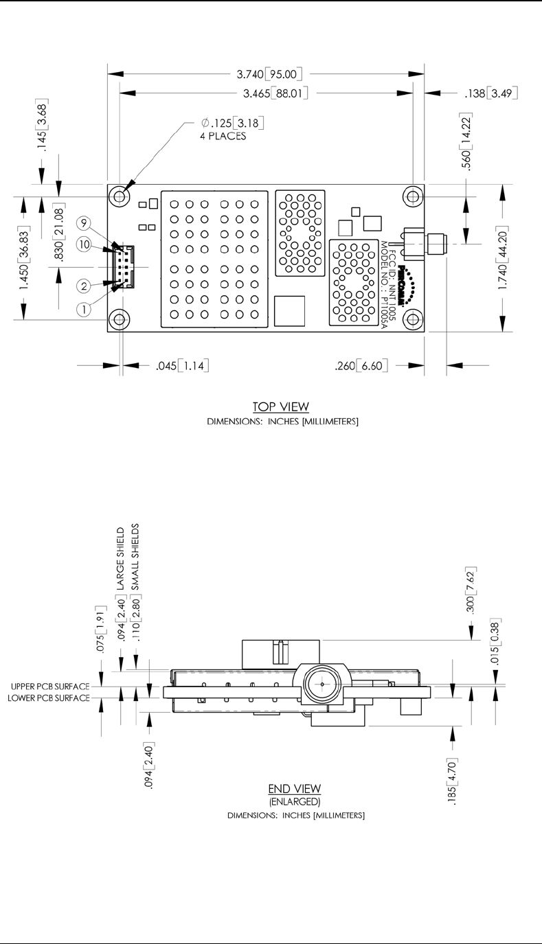
3.5 Mechanical Specifications
Please refer to Figure 2 and Figure 3 for mechanical specifications of the OMNIDATA
device.
12/2/02 User's Guide for the PerComm OMNIDATA Telemetry Device - PT1005A (DRAFT) 9
Document Number: 9400.01484-USG01 Revision 1.6 12/2/2002
Figure 2: OMNIDATA Mechanical Drawing – Top View
Figure 3: OMNIDATA Mechanical Drawing - End View
12/2/02 User's Guide for the PerComm OMNIDATA Telemetry Device - PT1005A (DRAFT)
10

Document Number: 9400.01484-USG01 Revision 1.6 12/2/2002
4 INSTALLATION AND OPERATION
4.1 Introduction
This chapter provides guidelines and procedures for correct installation and operation
of the PerComm OMNIDATA Telemetry Device.
4.2 Installation Setting
The installation setting must observe the guidelines listed below. Failure to comply with
these guidelines may cause the OMNIDATA device to operate improperly.
• The external antenna must be mounted in a location such that no person will
ever come within 8 inches of the antenna. This is required to comply with FCC
RF hazard regulations.
• The antenna must be installed in such a way that the main radiation pattern
generates vertical polarization. The antenna must conform to guidelines given
in Section 4.5.
• The device should be installed far from any switch mode power supply or
digital switching circuitry.
• The power supply should conform to requirements identified in Section 3.4.
• The device should not be subject to permanent vibrations.
• The device should not be subject to high magnetic fields.
• The device should be mounted in such a way that it makes no contact, or it is
not very close to any metallic object even if that object is connected to the
ground. There should be no other electrical contact to anything other than the
antenna and the flat cable for the power supply and host interface.
4.3 Installation Procedure
Follow the procedure outlined below to install the OMNIDATA device.
1. Install the External Antenna
a. The external antenna assembly consists of the following:
i. Larsen quarter wave antenna – part number SPWH20918
ii. Pasternack Enterprises (PE) SMA male to SMA female
bulkhead cable – part number PE3956-60
iii. 4” x 4” ground plane, aluminum or brass, 0.063 inches thick
b. Select a high, horizontal mounting surface for optimal performance.
The mounting surface must be no thicker than 1/8” (3mm) or problems
with the connector assembly may result.
c. Drill a 0.25 inch diameter hole in the mounting surface and the ground
12/2/02 User's Guide for the PerComm OMNIDATA Telemetry Device - PT1005A (DRAFT)
11

Document Number: 9400.01484-USG01 Revision 1.6 12/2/2002
plane.
d. Insert the SMA female bulkhead end of the PE cable through the hole
from below.
e. Secure the PE cable to the mounting surface and the ground plane with
a lockwasher and nut (supplied with the cable). Tighten the nut firmly
enough to solidly fix the connector, but take care not to overtighten.
f. Screw the Larsen antenna to the SMA female end of the cable just
installed. Firmly finger tighten. Do not attempt to use any tools to
tighten
2. Install the OMNIDATA Device
a. The OMNIDATA device consists of a single printed circuit board
assembly.
b. Install the OMNIDATA device using appropriate standoffs (e.g. Richco
part number LMSP-4-01).
c. Ensure that sufficient space is available to connect the antenna cabling,
host cabling and power supply cabling. Mechanical drawings of the
OMNIDATA device are shown in Section 3.5 to assist in this process.
d. Attach the SMA male end of the cable installed in step 1 above, to the
SMA female connector on the OMNIDATA device. Tighten the SMA
connector to 8-10 inch-pounds of torque. Over tightening can damage
the connector and reduce the performance of the OMNIDATA device.
3. Install the Host and Power Supply
a. Install the host and power supply. The host must conform to the
following guidelines:
i. The host supports the pin out specified in Table 5.
ii. The power supply must conform to the specifications identified
in Section 2.9.
iii. The host implements a supported host interface protocol (HCI
[2] or CLP [3].) Contact your service provider to determine
which protocol is enabled on your OMNIDATA device.
b. Connect the host and power supply to the OMNIDATA device’s host
interface header.
4. Turn on the Power Supply
a. Follow the instructions in Section 4.4.
4.4 Power-On Procedure
After power has been applied, follow the instructions listed here to verify operation of
the OMNIDATA device. Please refer to the appropriate host interface protocol
document (HCI [2] or CLP [3]) to determine how to execute these instructions.
12/2/02 User's Guide for the PerComm OMNIDATA Telemetry Device - PT1005A (DRAFT)
12

Document Number: 9400.01484-USG01 Revision 1.6 12/2/2002
1. Query the OMNIDATA device with the host. Verify that the host is able to
communicate with the OMNIDATA device.
2. Periodically poll the OMNIDATA device until the device has registered on the
ReFLEX network for full two-way service.
3. Use the host and OMNIDATA device to send a message to the PIN or email
address associated with the OMNIDATA device being used. Verify that the
message is successfully accepted by the ReFLEX network. Verify that the
message is successfully received by the OMNIDATA device.
4.5 External Antenna Impedance
The OMNIDATA transmitter was designed for a 50 ohms external antenna. The same
antenna is used for transmit and receive, hence the antenna has to work from 901MHz
to 941MHz.
It is possible to connect the external antenna directly to the device or through a coaxial
cable. The external antenna should be mounted close enough to the OMNIDATA unit to
limit the length of the cable and the losses in it. The external antenna assembly must
have a standard male SMA connector.
If the load presented by the external antenna assembly at the SMA port is not 50 ohms,
the output power of the transmitter and the DC current consumption during transmit
time may vary from theirs nominal values. The VSWR of the external antenna assembly
in the transmit band 901 to 902 MHz should be less than 1.7. If the VSWR is greater than
1.7 the transmitter might be permanently damaged. The solution is to have the antenna
re-matched or to impose restrictions on the length of the cable between the external
antenna and the unit. Please contact PerComm for further details.
12/2/02 User's Guide for the PerComm OMNIDATA Telemetry Device - PT1005A (DRAFT)
13