Perfect Toys Co SPORT-F2 Sport-F1 User Manual
Perfect Toys International Co Ltd Sport-F1 Users Manual
Manual
Digital Proportional Double-channels R/C System
P-30133P-30133
User's ManualUser's Manual
Rig ht
Left
Center
Steerin g control
Servo

Safety Direction
This model is not a toy! Err or operati on will cause danger! In ord er to operate sa fel y please
rea d fo llowings:
This model is not a toy! Err or operati on will cause danger! In ord er to operate sa fel y please
rea d fo llowings:
Notice Before Instal lation
Instal lation Prec aution
1. Make sure you have connected the battery polarity between tran smitter and rec eiver correctly or
yo u will damage the model.
2. You sh ould use corr esponding produces (su ch as tran sm itter, rec eiver, ESC and other optional
part s) pro duced by PERFECT company. We don't take any duty on the losing by using other
company' s products.
3.Changes or modifi cations not expres sl y appro ve d by the party res ponsi ble fo r compliance could vo id
the user' s authori ty to operate the equipment.
1. The product is designed for rem ote contro l model only. Never use for other se ttings.
2. Make sure to use tran sm itter crystal and rec eive r crystal only produced by PERFECT company.
Other crystal may cause losi ng control if you change fr equency.
3. If yo u are using Nicad batteri es, charge before using. Otherwise it will lose control fo r sh ort ing
electricity.
4. Make sure you have connected all instal lation corr ectly. The loose n connection will cause the
model losi ng control.
5. Instal l the rec eive r with thick double glue. Intensive oscillation and str ike will cause the model
losi ng control.
6. Never cut the antenna or tru ss it with other wire. Otherw ise the sense of the rec eiver will red uce
and the servo will get damaged.
7. Make sure to use the shockpro of wash er while instal ling the servo . The oscillation will damage
the se rvo and cause it losi ng control.
Operati on Prec aution
1. Ensure the frequency before turn ing on power sw itch. Some models usi ng the sa me fr equency
will res ult in running out contro l.
2. Avo id usi ng it at thunder sto rm day. The lightning may str ike the fi ttings thro ugh the antenna.
3. Avo id usi ng it in swamp place. Seri ous damp will cause the model losi ng control.
4. Never use the model in following surr oundings:
Near other telecontrol ve hicle circu it (in 10 meters) .
「 Near the cro wd or ru n on the pavement.
「 Near the wire and other communication instal lation.
Once the model lose s contro l it will cause danger.
5. Exten d the wire to the longest place or the signal will red uce and cause the model losing contro l.
6. Make sure you have sto pped engine operati on and cut the motor wires off before test and modify
the fun ction setting.
「

①
②
③
Charging Pre caution
1. Never let th e batt ery short circ uit or put it into fire or you will cause fi re and danger.
2. Never let th e batt eri es shake fiercely. Oth erw ise th e batt eries will be damaged and cause short
circ uit and fire .
3. Never let th e batt eri es get wet or charg e while the batteries are wet. Otherwise it will make th em
to o heat and cause damage.
4. Make sure to use the PERFECT charg er corre ctl y and use proper charg ing curre nt. Avoid over-
charging. Oth erwise you may damage th e batteri es and cause fi re and seri ous accident.
Noti ce Aft er Opera ti on
1. Make sure to cut off th e Nicad batteries after using th e electri c model vehicle. Oth erw ise th e
power switc hing on will cause fire and th e model will lose contro l.
2. Put the tran smitt er, batt ery and the model out of children's reach! Oth erw ise th e chemical mate ri al
will hurt th em.
3. Take the batteries out if you don't want to use th em fo r a long ti me.
4. Never sto re the tran smitter in following places:
Tempretu re over 40 and below -10 .℃ ℃
The sun shines dire ctly.
High dampness.
Sto ring the model in th e surro unding above will cause incorre ctl y operati ng and cause th e model
7. Remember to turn on the tran sm itter and rec eive r ord erl y while start ing. And opposi tely while
turn off . Otherwise you may cause the model losi ng control.
8. Let other people know your frequency while operati on.
9. Never touch the engine, motor and ESC if they are heat or you will burn yo urse lf.
10.The tran smitter se nds high frequency signal. Neve r touch the antenna while usi ng.

Catalogue
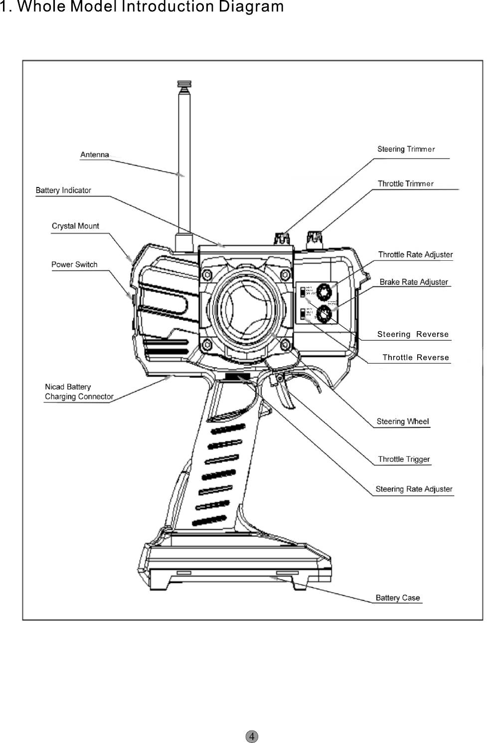
1. Whole Model Introduction Diagram
2. Transmitter Specification
3. System Configure and Connection
4. Installation and Operation
Installation of transmitter
A. Install the battery
B. Install the antenna
C. Install the receiver and servo
D. Change the direction adjusting wheel position
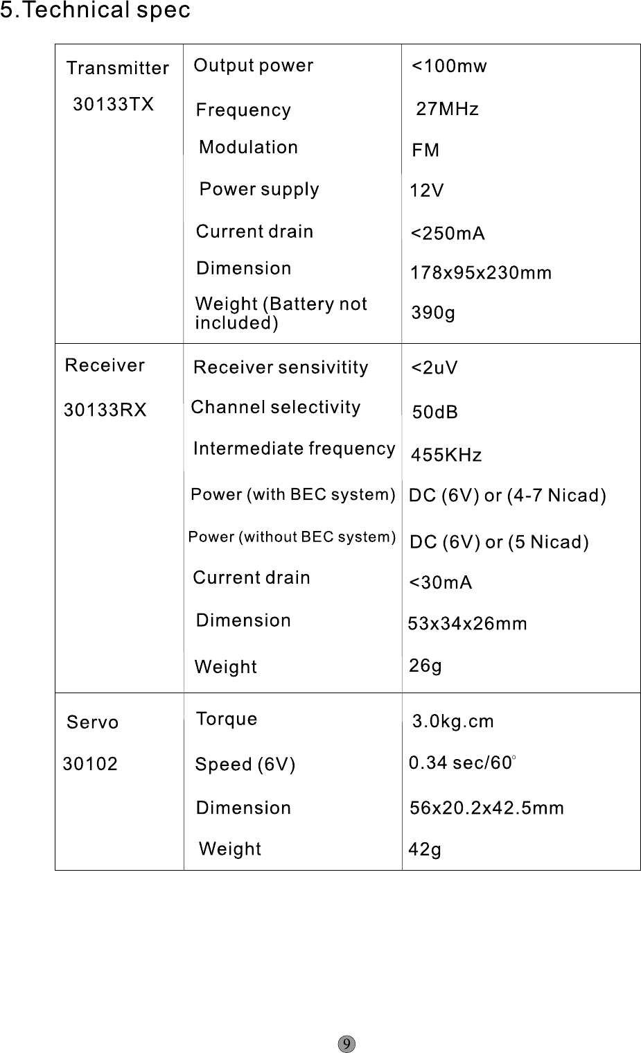
5. Technical Data
6. Fittings Packing
7. Production Service and Guarantee
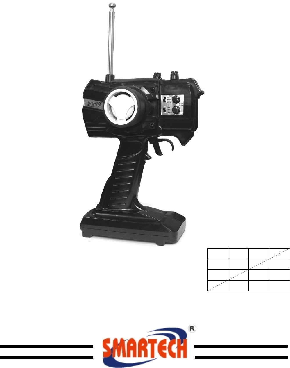
We lcome to use SMA RTECH series. Wi th high quality and advanced
technology, 30133 product will make your model optimal performance.
2. Character and Function
FM double-channels R/ C system
Do uble-channels servo front&r ear switch
Three battery indicator lights
Steering rate adjuster
Steering trimm er
Throttle rate adjuster
Br ake rate adjuster
Throttle trimm er
Ni cad battery charged interface
Steering adjusting wh eel position can be transposed into left hand and right hand expediently.
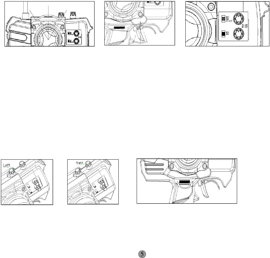
(1) Steering wh eel
The steering wh eel can be rotated 35 degree from left and right. (See picture 1)
(2) Throttle trigger
Throttle trigger can mov e 20 degrees forwa rds and backwards. (See picture 2)
(3) Servo reverse
The servo can reversely revolve wi th its reversed switch.
The servo can revolve clockwise when the switch is on the 'NOR ' position.
The servo can contrarotate when the swi tch is on the 'RE V' position. (See picture 3)
(4) Steering trimm er
Ro tating the left button on the top can obtain neutral position of the steering servo.
(See picture 4)
(5) Throttle trimm er
Ro tating the right button on the top can obtain neutral position of the throttle servo.
(See picture 5)
(6) Steering rate adjuster
The steering servo routing can be adjusted betwe en its 30% -100% approximately.
Ad justing knob can rotate 300 degrees.
The routing of the potentiometer wi ll increase when revolving right and wi ll decrease when
revolving left. (See picture 6)
Picture 1 Picture 2Picture 3
Picture 4Picture 5Picture 6
(7) Throttle rate adjuster
The throttle servo routing can be adjusted betwe en its 30% and 100%.
Ad justing knob can rotate 300 degrees.
THTH
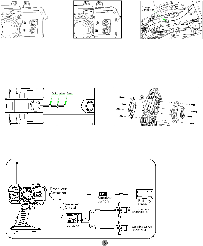
When revol vi ng clockw ise the rout ing of the knob will incr eas e.
The rout ing will decease whi le cont rar ot at ing. (See pi ct ur e 7)
(8) Brake rate adj ust er
The thr ot tle brake ser vo' s rout ing can be adj ust ed bet ween its 30% and 10 0% .
Adj ust ing knob can rot at e 30 0 degre es.
When revol vi ng clockw ise the rout ing of the knob will incr eas e.
The rout ing will decease whi le cont rar ot at ing. (See pi ct ur e 8)
(9) Char gi ng connect or
Not ice: You can char ge onl y when the pow er is tur ned of f. Slide the switch dow nw ar ds to turn
of f the pow er. The char ger can onl y char ger to the char ger abl e bat teries. Usi ng ot her type of
bat teries will dam age the equi pm ent or be dangerous to the per son. (See pi ct ur e 9)
Never char ge to the unchar ger abl e bat ter ies.
CAUTION:use bat tery onl y in descr ibed manner and di spose of used bat teries under
envi ronm ent al aspect s accor ding to the inst ruct ion.
-Don' t di spose the used bat ter ies in the nor mal ly househol d wast e, Thi s must br ing back to
the deal er or ot her speci al poi nt s and di sposed under envi ronm ent al aspect s.
-Consi der the pol ar ity of the bat ter ies at the changi ng.
Never char ge to the unchar ger abl e bat ter ies.
(10) Power indicator lights
You need to change or charg e th e batt eries when the LED only shows yellow and red.
Never opera te th e batt eri es when the LED only shows red since the electr icity is very weak
when the yellow and gre en lights isn't lighte ned. (See pictu re 10)
(11) Transpose wheel dire ction
You can change ste eri ng wheel positi on if you want to operate by your left hand. (See pictu re 11)
Picture 7Picture 8 Picture 9
Picture 1 0 Picture 1 1
3. System Configuration
Configure and connect the system by following figures.
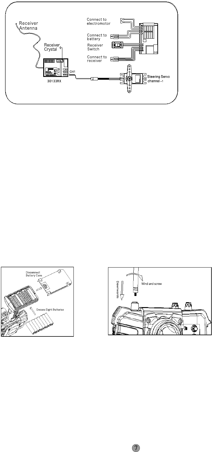
(1) Tank vehicle configuration(BEC function) (See picture 12)
Picture 12
4. Instal ling Operat ion
To av oid unnec es sary lose , plea se read following inst ructi on
ca reful ly before instal ling.
a. Inst al l batt eri es
You need 8 al ka line batt eri es or Nica d batt eri es .
1. Open the batt ery co ve r by the picture.
2. Fix on 8 batt eri es an d take ca re to the polari ty.
3. Push down the batt ery co ve r to close it.
If yo u use Nicad batt eri es, plea se use SMARTECH intelligen t
ch arg er (NO.40108) to charg er for 1-5 hours. (See picture 14)
(2) Elec trical ve hicl e co nfigurati on with elec tron spee d ad juster (See picture 13)
b.Anten na inst al lati on
Inst al l the anten na by the picture an d screw it tightly.
Mak e su re yo u have inst al led the an ten na correc tly an d pulled to
the longest posi tion before usi ng. Or the co ntrolling dist an ce will
be aff ec ted and yo ur model will be dam ag ed . (See picture 15)
Picture 1 3
Picture 1 4 Picture 1 5
c. Inst al l the rec ei ve r an d se rvo
30133RX Rec ei ve r
Without Batt ery Elimintor Circust ry (BEC) system , the rec ei ve r only nee d 4 dry ce lls an d 5 Nica d
piles (6V). Too high voltag e will dam ag e the rec ei ve r an d se rvo .
With Batt ery Elimintor Circu st ry (BEC) system , the ci rcuit hav e vo ltage reg ulators. You ca n use
4 dry ce lls or 4-7 Nica d piles (4.8-8.4V) to ch arg e for the rec ei ve r. When the rec ei ve r has vo ltag e
reg ulators it will charg e for the servo . Too high vo ltag e will dam ag e the rec ei ve r an d se rvo .
.
(1) Push the co nnec ting switch on OFF posi tion.
(2) Inse rt the switch co nnec tor into the recei ve r BATT groove .
Avo id usi ng one power for rec ei ve r, motor and en gine at the sam e time
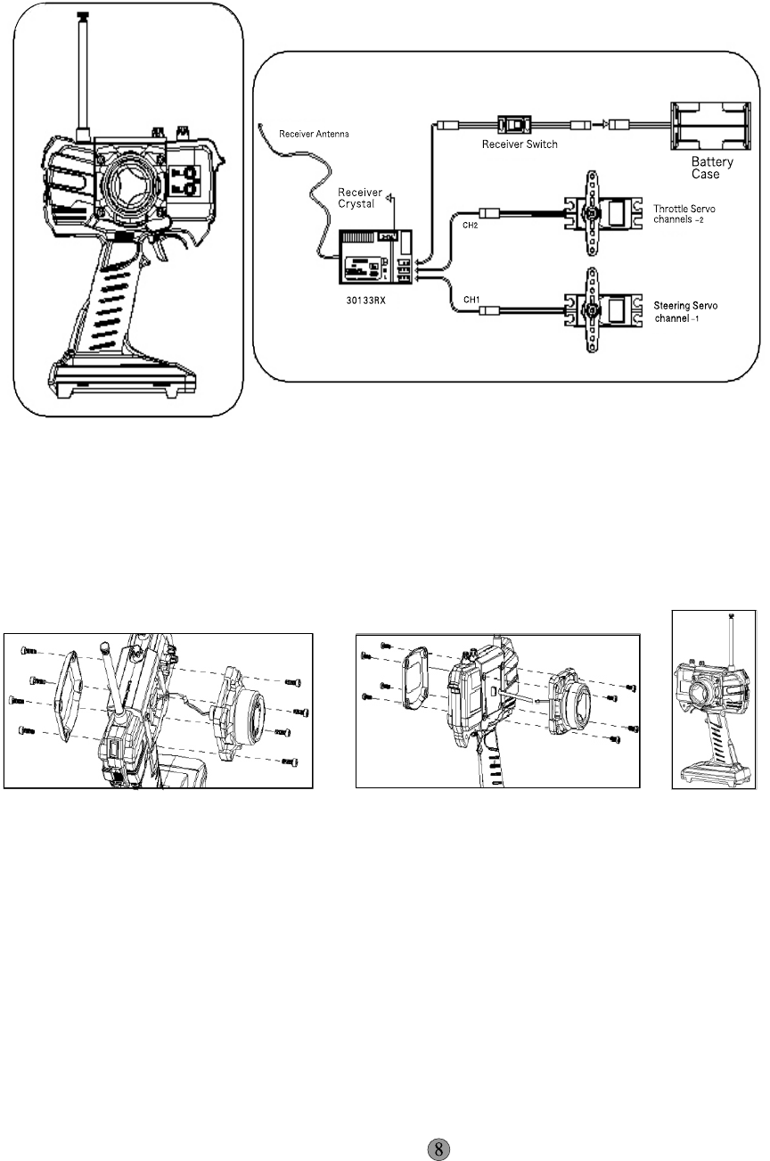
(3) Plug th ro tt le servo connecto r into CH2 channel.
(4) Plug dire cti on serv o into CH1 channel.
(5) Instal l 4 AA alkaline batt ery into batt ery case (or BEC syste m : 4-7 CELL Nicad piles; with out
BEC syste m: 5 CELL Nicad piles) and connect th e port with the re ceiver switch inte rfa ce.
(6) Check wheth er the re ceiver crystal suit with transmitt er cry stal .
(7) Turn on th e tr ansmitt er.
(8) Put servo switch on "ON" position. (See pictu re 16)
d. Transposing directi on and steering wheel positi on
(1). Tweak 4 inner hexagon screws on ste eri ng wheel fi xer.
(2). Take out ste ering wheel slightl y and plug out th e pin by pictu re . (See pictu re 17)
(3). Tweak 4 inner hexagon screws on rear fixing board .
(4). Insert adjusting wheel pin into CH1 socket and fix th e scre w. (See pictu re 18)
(5). Fix th e re ar board on th e ste eri ng wheel position. (See picture 19)
Picture 17Pictu re 18Pictu re 19
Picture 16

7. Product service and guarantee
Our product have tested st rict ly before sh ipmen t. If the product is dam ag ed not by man made
ac tor plea se co ntac t with our dealer. The cu st oms will tak e resp onsi bility for the damag e ca used
by yo ur err or operat ion. If you have an y questi on while inst al ling an d debugging plea se co ntac t
with our dealer. We will warm ly servi ce for yo u. We will constan tly improve and upgrade
SMARTECH product without prior notice . Fi nal ly, we hope that you ca n en joy yoursel ves with our
R/C product s.
NOTE:This equipment has been tested and found to comply with limits for a Class B digital
device,pursuant to Part 15 of the FCC Rules.These limits are residential installation.This
equipment generates,uses and can radiate radio frequency energy and,if not installed and
used in accordance with the instructions,may cause harmful interference to radio
communications,However,there is no guarantee that interference will not occur in a particular
installation.If this equipment does cause harmful interference to radio or television reception,
which can be determined by turning the equipment off an on,the user is encouraged to try to
correct the interference by one or more of the following measures:
-Reorient or relocate the receiving antenna.
-Increase the separation between the equipment and receiver.
-Connect the equipment into an outlet on a circuit different from that to which the receiver
is connected.
-Consult the dealer or an experienced radio TV technician for help.
The users manual or instruction manual for an intentional or unintentional radiator shall
caution the user that changes or modifications not expressly approved by the party
reaponsible for compliance could void the user's authority to operate the equipment.In cases
where the manual is provided only in a form other than paper,such as on a computer disk or
over the Internet,the information required by this section may be included in the manual in that
alternative form,provided the user can reasonably be expected to have the capability to access
information in that form.