Persistent systems RF2100 S-Band Radio Module User Manual 1
Persistent systems LLC S-Band Radio Module Users Manual 1
Contents
- 1. Users Manual 1
- 2. Users Manual 2
Users Manual 1
MPU5
BASIC OPERATOR MANUAL
VERSION 2.0

Copyright 2010 - 2016 Persistent Systems, LLC. Wave Relay® is a registered trademark of Persistent Systems, LLC. All
rights reserved. This Basic Operator Manual contains information that is the sole property of Persistent Systems, LLC
and may not be excerpted, summarized, copied or published without the written permission of Persistent Systems, LLC.

Copyright 2010 - 2016 Persistent Systems, LLC
Issued: January, 2016
READ MANUAL BEFORE OPERATION
PERSISTENT SYSTEMS
Headquartered in New York City since 2007, Persistent Systems LLC is a global communications
technology company which develops, manufactures and integrates a patented and secure Mobile
Ad Hoc Networking (MANET) system: Wave Relay® . The company’s industry-leading R&D team has
designed wireless networking protocols to support their cutting edge Wave Relay® system and has
designed MIMO radios to allow the Wave Relay® MANET to achieve its highest potential. Wave Relay®
is capable of running real-time data, video, voice and other applications under the most difficult and
unpredictable conditions. Their suite of products is field proven and utilized in Commercial, Military,
Government, Industrial, Agriculture, Mining, Oil and Gas, Robotics, and Unmanned System markets.
THE MPU5
The MPU5 is the Next Generation Wave Relay® platform. Leveraging multiple leading edge technologies
such as MIMO and Android™, the MPU5 is a smart radio that delivers increased performance, reliability,
and capability to the end user in a small, cost-efficient package. Stream multiple HD Video feeds, run
commercial and custom apps, view situational awareness, and communicate with high quality audio
all with a single device and a minimal number of accessories.
WAVE RELAY® MANET
The Wave Relay® System is a peer-to-peer wireless MANET networking solution in which there is no
master node. If any device fails, the rest of the devices continue to communicate using any remaining
connectivity. By eliminating master nodes, gateways, access points, and central coordinators from the
design, Wave Relay® delivers high levels of fault tolerance regardless of which nodes might fail. The

system is designed to maximize the capacity of the radio frequency (RF) spectrum and to minimize
the network overhead. While optimizing efficiency, Wave Relay® also implements tech niques that
increase multicast reliability. The advanced multicast functionality allows the system to support both
multicast voice and video over IP.
Wave Relay® is designed to maintain high bandwidth con nectivity among devices that are on the
move. The system is scalable, enabling it to incorporate unlimited meshed devices into the wireless
network, where the devices themselves form the communication infrastructure. Even in highly dynamic
environments, the system is able to maintain connectivity by rapidly re-routing data as necessary. Wave
Relay® is a self-forming and self-healing network where nodes can move freely within the network.
Critical information flows reliably throughout the network while individual data paths are able to adapt at
sub-second intervals. This unique approach creates an ideal environment for maximizing performance
across the available communications medium. Customers leverage Wave Relay®’s straight forward and
effective architecture to enable a true “Plug and Play” capability. Deploying a Wave Relay® network is as
simple as connecting a standard Ethernet cable; customers are immediately connected to everything on
the network.
Wave Relay® is a seamless wireless networking system offering a dynamic and reliable solution for all
mobile networking needs. The MPU5 offers the Wave Relay® MANET combined with other leading
edge technologies in a single smart radio.

© 2010 - 2015 Persistent Systems, LLC – All Rights Reserved
6
TABLE OF CONTENTS
Introduction 4
Persistent Systems 4
The MPU5 4
Wave Relay® MANET 4
Safety 12
Suggested Hardware 16
Part I: Physical Setup 17
Section A: RF Setup 17
Inserting the Radio Module 20
Connecting Antennas 22

© 2010 - 2015 Persistent Systems, LLC – All Rights Reserved 7
TABLE OF CONTENTS
Section B: Power 26
Connecting Power 28
Removing Power 30
Powering On the Unit 32
Section C: Side Connector Cables 34
Parts List/Interchangeable Parts 35
Connecting a Cable to a Side Connector 36
Part II: Software Setup 40
Section A: Configuring the Management Computer 40
Parts List/Interchangeable Parts 40
Configuring the Management Computer (Windows) 42

© 2010 - 2015 Persistent Systems, LLC – All Rights Reserved
8
TABLE OF CONTENTS
Configuring the Management Computer (Linux) 50
Connecting the MPU5 to the Management Computer 51
Parts List/Interchangeable Parts 51
Accessing the Web Management Interface 51
Parts List/Interchangeable Parts 54
Security Key 62
Assigning IP Address and Interface Names 64
Rebooting an Individual Node 67
Part III: Testing Connectivity 68
Check Neighbor Node Status 68
Perform a Throughput Test 70

© 2010 - 2015 Persistent Systems, LLC – All Rights Reserved 9
TABLE OF CONTENTS
Part IV: Using the Web Management Interface 72
View Individual Node Information 72
Configuring Radio Settings for a Single Node 74
Upgrading Firmware 76
Creating a Configuration File 78
Loading Settings from a Configuration File 79
Reset Node to Factory Configuration 80
Check GPS Status 81
Part V: Device Operation 82
Zeroize the Security Key 82
Connect a Camera to the MPU5 84

© 2010 - 2015 Persistent Systems, LLC – All Rights Reserved
10
TABLE OF CONTENTS
Connect an EUD or Handheld Display to the MPU5 86
Connecting a Monitor or TV to the Wave Relay® MPU5 88
Connect USB Accessories to the MPU5 91
Install Android™ Apps on the MPU5 93
Connect a PTT Device to the MPU5 98
Configure PTT Settings 100
Enable Push-to-Talk 101
Set Earpiece Volume 101
Set Microphone Level 102
Set Transmit Mode 103
Set Transmit or Receive Audible Checktone 104

© 2010 - 2015 Persistent Systems, LLC – All Rights Reserved 11
TABLE OF CONTENTS
Enable/Disable Low Battery Audible Notification 105
Selecting Channels 106
Customize a PTT Channel 107
Using Wave Relay® Push-to-Talk 108
Using Flash Override 109
Professional Installer – Compliance 110
Attachments 114

© 2010 - 2015 Persistent Systems, LLC – All Rights Reserved
12
SAFETY
Lire et comprendre les consignes de sécurité d’emploi et tout
de l’opérateur avant d’utiliser cet équipement
SAFETY WARNINGS
Handle Safely: • Falling while installing or removing equipment can cause serious injury.
• If installing on a tower or any other tall locations, use proper lifting tech-
niques and wear proper protective equipment.
• Tomber lors de l’installation ou de retirer l’équipment peut causer des
blessures graves.
• Si vous installez sur une tour ou d’autres endroits de hauteur, utiliser des
techniques de levage appropriées et porter un équipment de protection
approprié.

© 2010 - 2015 Persistent Systems, LLC – All Rights Reserved 13
SAFETY
Electrical Shock
and Fires:
• Understand and follow all local codes and regulations when installing elec-
trical equipment.
• Only use approved battery and/or power supplies.
• Comprendre et respecter tous les codes et règlements locaux lors de l’in-
stallation des équipements électriques.
• Utilisez uniquement la batterie et les alimentations ou approuvé.
RF Exposure: • Prevent injury from exposure to high frequency fields.
• See antenna separation instructions in the Compliance section of this man-
ual.
• Do not operate with antenna removed. This can increase RF exposure
risks and/or damage the equipment.
• Prévenir les blessures d l’exposition aux champs de haute fréquence.
• Voir les instructions de séparation de l’antenne dans la section de la con-
formité de ce manuel.
• Ne pas faire fonctionner avec antenne enlevé. Cela peut augmenter les
risques d’exposition aux radiofréquences et ou endommager l’équipe-
ment.

© 2010 - 2015 Persistent Systems, LLC – All Rights Reserved
14
SAFETY
CAUTION
DEVICE UTILIZES LITHIUM ION BATTERY
RISK OF EXPLOSION IF BATTERY IS REPLACED BY AN INCORRECT TYPE.
DISPOSE OF USED BATTERIES ACCORDING TO THE INSTRUCTIONS
----------------------------------------------------------------------
MISE EN GARDE
Dispositif utilise la batterie Ion Lithium
RISQUE D’EXPLOSION SI LA BATTERIE EST REMPLACE PAR UN TYPE INCORRECT.
Jetez les piles usagées selon
LES INSTRUCTIONS
Lithium Batteries Handling
• Lithium ion batteries are defined as Class 9 dangerous goods by the IATA Dangerous Goods
Regulations.
• Handle with care.
• Do not use if package is damaged - it can cause fire.
Disposing of Used Batteries
• Disposal should be done in accordance with applicable regulations, which vary from country to
country as well as by state and local governments. In most countries, trashing of used batteries
is forbidden and disposal can be done through non-profit organizations mandated by local au-

© 2010 - 2015 Persistent Systems, LLC – All Rights Reserved 15
SAFETY
thorities or organized by professionals.
• Incineration of lithium cells and batteries by consumers is not recommended. Incineration
should be done at a properly permitted facility that can handle this waste.
---------------------------------------------------------------------------------------------------
Manipulation des batteries lithium
• Les batteries au lithium-ion sont définis comme Classe 9 marchandises dangereuses par le Régle-
ment sur les marchandises dangereuses de l’IATA.
• Manipuler avec soin.
• Ne pas utiliser si l’emballage est dommage, il peut provoquer un incendie.
Mise au rebut des batteries usagées
• L’élimination doit être effectuée conformément aux réglementations applicables, qui varient
d’un pays à l’autre ainsi que par les gouvernements d’État et locaux. Dans la plupart des pays
saccage des batteries usagées est interdit et l’élimination peut être fair par les organisations à
but non lucratif mandatés par les autorités locales ou organisées par des professionnels.
• Incinération des dellules et batteries au lithium par les consommateurs est déconseillée. In-
cinération devrait être fait dans une installation dûment autorisée qui peut gérer ces déchets.
See Attached Battery Spec Sheet, MSDS, and compliance document for more information

© 2010 - 2015 Persistent Systems, LLC – All Rights Reserved
16
SUGGESTED ADDITIONAL HARDWARE
Suggested Additional Hardware
▶Torque Wrench: Used to attach/detach radio module
▶TPI Kit: Allows for antenna and RF cable matching
▶RF cable at various lengths (LMR-400): Allows for flexibility in antenna setup
▶Ethernet Cables
▶Ethernet Female-to-Female Extenders
▶HD Screen or TV with HDMI input: Displays Android™ computer interface and/or streaming
video
▶Laptop with Administrator Access: Used for device configuration
▶USB Thumb Drives: Used for software configuration storage and loading

© 2010 - 2015 Persistent Systems, LLC – All Rights Reserved 17
PHYSICAL SETUP: RF SETUP
What Will I Learn?
▶How to attach antennas to the MPU5
▶How to insert radio modules into the MPU5 chassis
→
Section A: Power
Part I: Physical Setup
© 2010 - 2015 Persistent Systems, LLC – All Rights Reserved
18
PHYSICAL SETUP: RF SETUP

© 2010 - 2015 Persistent Systems, LLC – All Rights Reserved 19
PHYSICAL SETUP: RF SETUP
?How do I tell if my antennas and radio modules are compatible?
Quick Reference:
ANT- or RF-1xxx – L-Band (1.35 - 1.39 GHz)
ANT- or RF-2xxx – S-Band (2.2 - 2.5 GHz; EDM: 2.3 - 2.5 GHz)
ANT- or RF-3xxx – C-Band (4.4 - 4.8 GHZ or 4.9 - 5.8 GHz) *in development
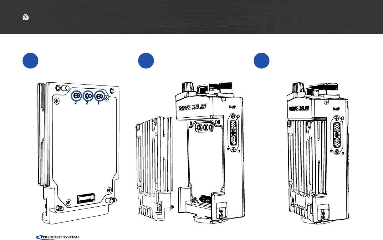
Find the part numbers on the antennas. Antenna part numbers are on a sticker wrapped around the base
of the antenna.
1
Find the part number on the radio module. The radio module part number is on a sticker on the back of
the radio module.
2
Each part number will begin with ANT- (antennas) or RF- (radio modules) followed by four (4) digits. The
first digit references the radio band of the part. Make sure that the first digit of the antennas and radio
module match.
3
!WARNING!: DO NOT use mismatched antennas and radio modules. This configuration will result in very
poor performance if it works at all. If you do not have matching antennas and radio modules, contact Persistent
Systems.
!WARNING!: User MUST refer to the Professional Installer – Compliance Section of this manual for ap-
proved antenna types.
© 2010 - 2015 Persistent Systems, LLC – All Rights Reserved
20
PHYSICAL SETUP: RF SETUP
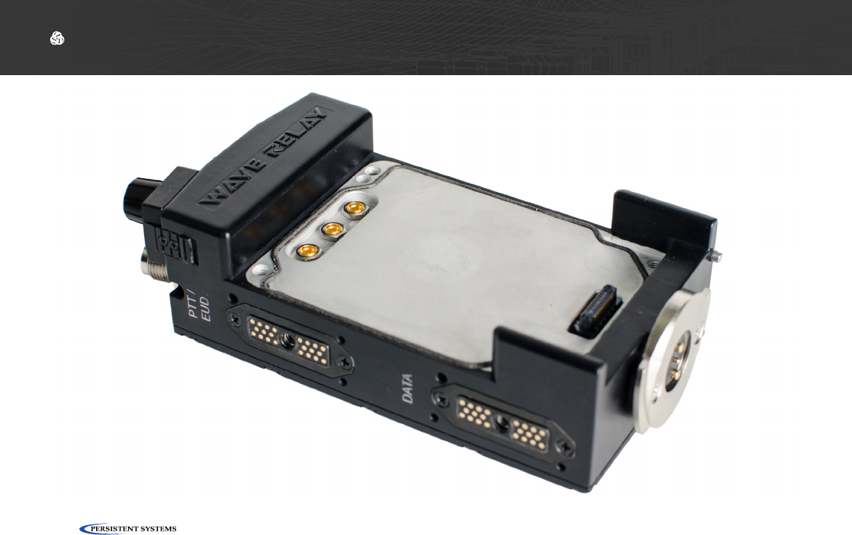
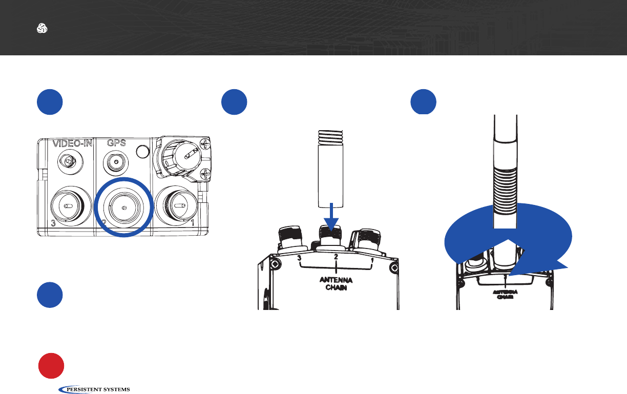
Inserting the Radio Module
1If there are rubber caps
on the radio module
contacts, remove them.
2Align the radio module
with the chassis. 3Press the radio module
into the chassis.
© 2010 - 2015 Persistent Systems, LLC – All Rights Reserved 21
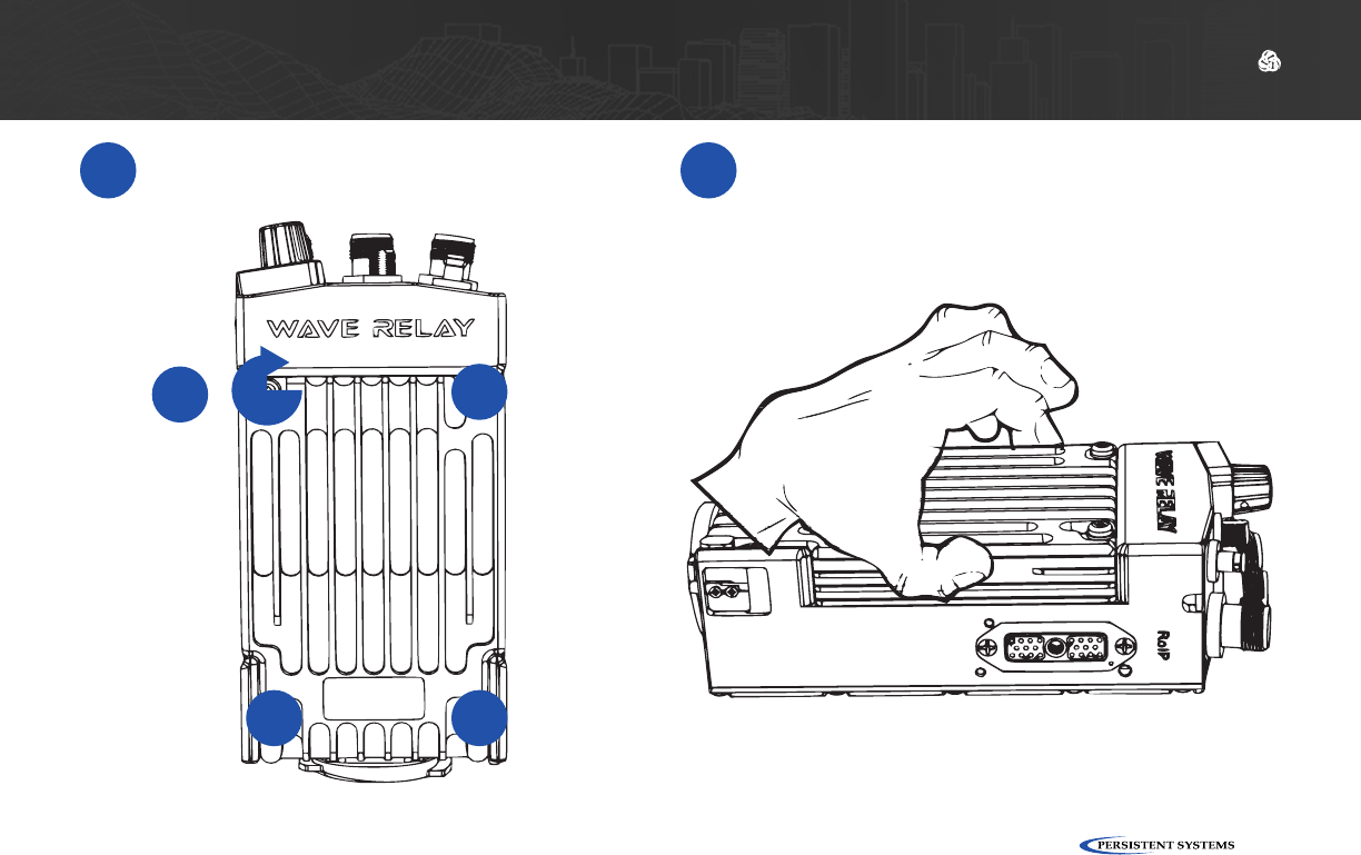
PHYSICAL SETUP: RF SETUP
4Torque screws clockwise to 6 in lbs in
diagonal order. 5Pull on the radio module to verify that it is
attached securely.
1
2
3
4
© 2010 - 2015 Persistent Systems, LLC – All Rights Reserved
22
PHYSICAL SETUP: RF SETUP
1Start with the middle
antenna port. 2Align the RF connector
on the antenna with the
RF connector on the unit.
3Twist the antenna clock-
wise until it is fully mated.
Connecting Antennas
▶You can use a TPI Kit and/or extra LMR-400 RF Cables to remote antennas away from the unit. This setup is particu-
larly useful for mounted or operations center configurations.
▶To operate in SISO mode, you only need to attach an antenna to the antenna port for the chain you want to use.
WARNING!: if you want to operate in SISO mode, unused antenna chains MUST be turned off.
Tips & Tricks
T
!
© 2010 - 2015 Persistent Systems, LLC – All Rights Reserved 23
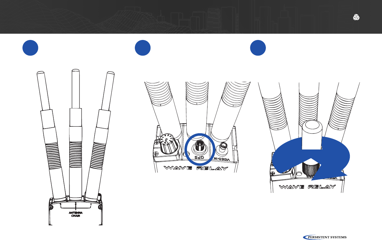
PHYSICAL SETUP: RF SETUP
4Repeat Steps 1 - 3 for
the remaining two RF
antennas.
5Align the SMA connec-
tor on the GPS antenna
with the SMA connector
on the unit.
6Twist the antenna clock-
wise until it is fully mated.

© 2010 - 2015 Persistent Systems, LLC – All Rights Reserved
24
PHYSICAL SETUP: RF SETUP
How do I ensure that the radio
module is aligned properly?
?
The three RF connectors on the radio module will
align with the three RF connectors on the chassis.
When aligned properly, the engraved writing on the
radio module will be facing the same direction as
the writing on the chassis.
What do I do if the radio module
won’t insert into the chassis?
?
Ensure that the radio module is aligned properly.
Ensure that the connectors on the radio module are
not bent.
Ensure that there are no foreign objects in any of
the connectors, on the bottom of the radio module,
or in the chassis well.
1
2
3
What do I do if the antennas won’t
screw onto the RF connectors?
?Ensure that you are using antennas with RP-TNC
Male connectors or an appropriate adapter from
your TPI kit.
Ensure that the connectors on both the unit and
antennas are not damaged.
Ensure that there are no foreign objects in any of
the connectors.
1
2
3
How do I tell if the antennas are
connected properly?
?When an antenna is mated properly, the threads on
the connector will not be visible. However, there
may be a small space between the antenna and the
chassis.
1

© 2010 - 2015 Persistent Systems, LLC – All Rights Reserved 25
PHYSICAL SETUP: RF SETUP
What Can I Do Now?
✓
▶Swap radio modules and antennas to change the RF band you are capable of operating on
▶Swap out broken radio modules and antennas
▶Setup hardware to receive GPS connectivity
▶Remote antennas away from the unit

© 2010 - 2015 Persistent Systems, LLC – All Rights Reserved
26
How can I use my old power accessories from previous Wave Relay products with my
MPU5?
?
You can use your MPU4 twist locking battery pack or BB batteries with the MPU5. You CANNOT use old battery
eliminators with the MPU5. The MPU5 accepts 12 - 24V input power, unlike previous Wave Relay® products.
You CANNOT power the MPU5 via Power over Ethernet (PoE).
PHYSICAL SETUP: POWER
What Will I Learn?
▶How to connect a power source to the MPU5
▶How to power on the MPU5
→
Section B: Power

© 2010 - 2015 Persistent Systems, LLC – All Rights Reserved 27
PHYSICAL SETUP: POWER