Persistent systems RF5100 MPU5 Upper C-BAND Radio Module User Manual
Persistent systems LLC MPU5 Upper C-BAND Radio Module
UserManual.wiki
>
Persistent systems
>
RF5100 User Manual
User Manual
Navigation menu
Upload a User Manual
Namespaces
Wiki Guide
HTML
PDF
Info
Views
User Manual
Discussion / Help
Navigation


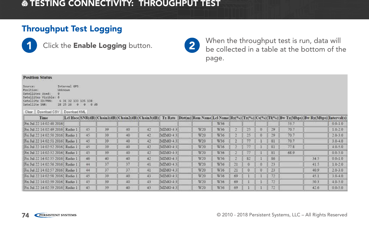
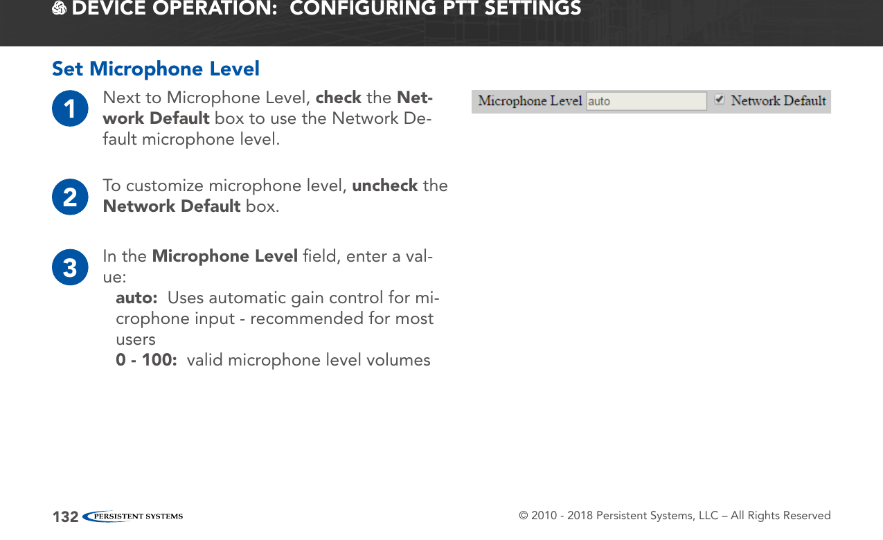
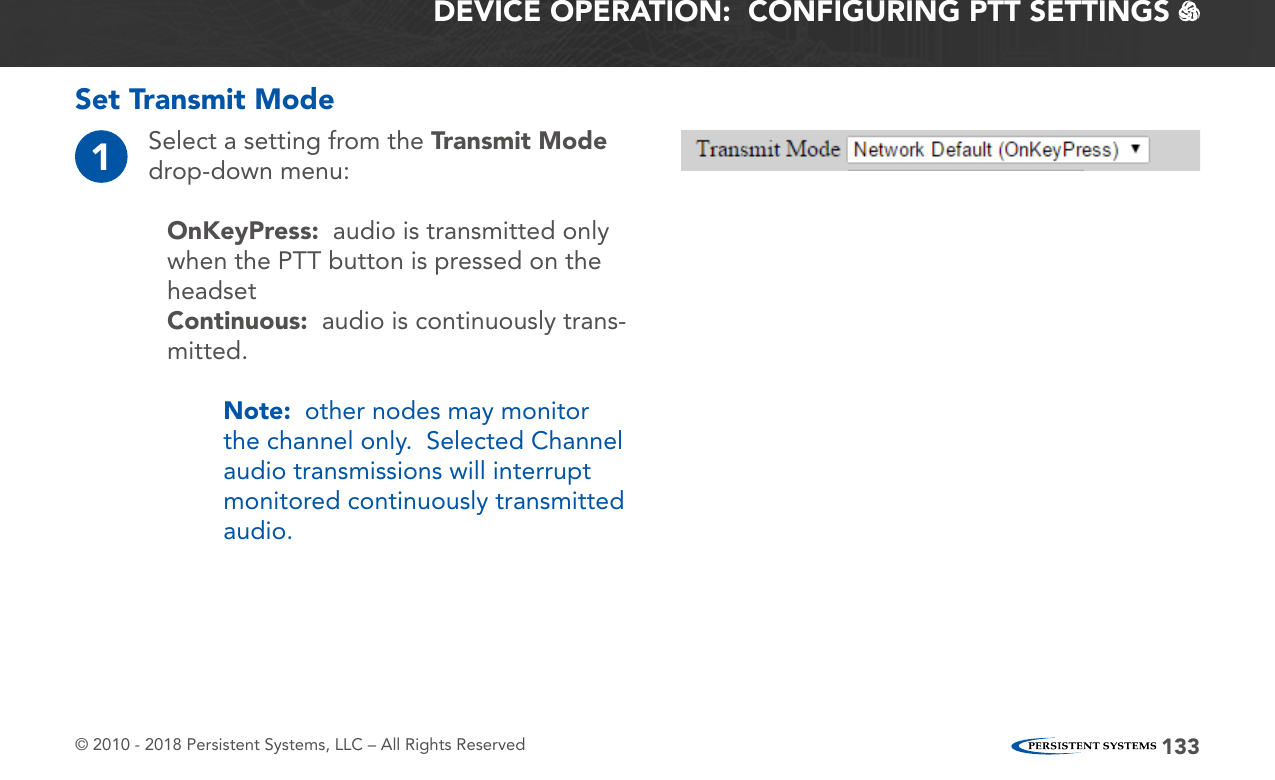
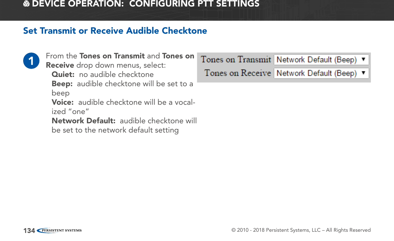
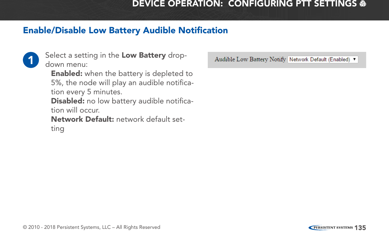
![© 2010 - 2018 Persistent Systems, LLC – All Rights Reserved 75TESTING CONNECTIVITY: THROUGHPUT TEST Position Status: displays GPS status information for the current node. See the Check GPS Status section for an explanation of these fields.Clear: clears all data from the tableNote: If Clear is not pressed before beginning a test, the new throughput test data will be append-ed sequentially to the existing table of data.Download CSV: downloads all throughput test data in the table as a CSV fileDownload KML: downloads all throughput test data in the table as a KML fileTime: date and time for each line of test dataInterface: interface used to communicate during the testSNR (dB): Signal-to-Noise Ratio at which the destination node is heardChain 1/2/3 (dB): Signal-to-Noise Radio for each chain on the source nodeTx Rate: MIMO or SISO rate used to communicate between nodes in the format MIMO|SISO [Rate]:[Number of streams].Dist (m): distance between nodes, in meters, if availableRem Name: Node Name of the destination nodeLcl Name: Node Name of the source nodeRx(%): percentage of the channel used to receiveTx(%): percentage of the channel used to transmitCs(%): percentage of the channel occupied by noiseTl(%): total percentage of channel usedBw Tx (Mbps): Upload Bandwidth, in MbpsBw Rx (Mbps): Download Bandwidth, in MbpsInterval (s): time interval of the throughput test for each line of throughput test data](https://usermanual.wiki/Persistent-systems/RF5100/User-Guide-3981069-Page-75.png)