Persistent systems RF5100 MPU5 Upper C-BAND Radio Module User Manual
Persistent systems LLC MPU5 Upper C-BAND Radio Module
User Manual
MPU5
BASIC OPERATOR MANUAL
VERSION 2.5
03EN073
Rev. G

Copyright 2010 - 2018, Persistent Systems, LLC. All rights reserved. Wave Relay® is a registered trademark of Persistent Systems, LLC
(“Persistent”). This Basic Operator Manual (the “Manual”) contains information that is the sole property of Persistent Systems, LLC.
Therefore, the Manual may not be excerpted, summarized, copied, distributed, or otherwise published, in whole or in part, without
the prior written permission of Persistent Systems, LLC. All other product and service names, trademarks, logos, and brands are
property of their respective owners. All non-Persistent company, product, and service names and all non-Persistent trademarks used
in this Manual are for identification purposes only. Use of these non-Persistent names, trademarks, logos, and brands does not imply
endorsement.

Copyright 2010 - 2018 Persistent Systems, LLC
Issued: July, 2018
READ MANUAL BEFORE OPERATION
DO NOT SWAP RADIO MODULES WHILE UNIT IS POWERED ON!
DO NOT POWER ON UNIT WITHOUT ANTENNAS ATTACHED!
PERSISTENT SYSTEMS
Headquartered in New York City since 2007, Persistent Systems LLC is a global communications technology company
which develops, manufactures and integrates a patented and secure Mobile Ad Hoc Networking (MANET) system: Wave
Relay® . The company’s industry-leading R&D team has designed wireless networking protocols to support their cutting
edge Wave Relay® system and has designed MIMO radios to allow the Wave Relay® MANET to achieve its highest
potential. Wave Relay® is capable of running real-time data, video, voice and other applications under the most difficult
and unpredictable conditions. Their suite of products is field proven and utilized in Commercial, Military, Government,
Industrial, Agriculture, Mining, Oil and Gas, Robotics, and Unmanned System markets.
THE MPU5
The MPU5 is the Next Generation Wave Relay® platform. Leveraging multiple leading edge technologies such as MIMO
and Android™, the MPU5 is a smart radio that delivers increased performance, reliability, and capability to the end user
in a small, cost-efficient package. Stream multiple HD Video feeds, run commercial and custom apps, view situational
awareness, and communicate with high quality audio all with a single device and a minimal number of accessories.
WAVE RELAY® MANET
The Wave Relay® System is a peer-to-peer wireless MANET networking solution in which there is no master node. If any
device fails, the rest of the devices continue to communicate using any remaining connectivity. By eliminating master
nodes, gateways, access points, and central coordinators from the design, Wave Relay® delivers high levels of fault
tolerance regardless of which nodes might fail. The system is designed to maximize the capacity of the radio frequency
(RF) spectrum and to minimize the network overhead. While optimizing efficiency, Wave Relay® also implements tech-
niques that increase multicast reliability. The advanced multicast functionality allows the system to support both multicast
voice and video over IP.
Wave Relay® is designed to maintain high bandwidth con nectivity among devices that are on the move. The system
is scalable, enabling it to incorporate unlimited meshed devices into the wireless network, where the devices
themselves form the communication infrastructure. Even in highly dynamic environments, the system is able to

maintain connectivity by rapidly re-routing data as necessary. Wave Relay® is a self-forming and self-healing network
where nodes can move freely within the network. Critical information flows reliably throughout the network while
individual data paths are able to adapt at sub-second intervals. This unique approach creates an ideal environment
for maximizing performance across the available communications medium. Customers leverage Wave Relay®’s
straight forward and effective architecture to enable a true “Plug and Play” capability. Deploying a Wave Relay®
network is as simple as connecting a standard Ethernet cable; customers are immediately connected to everything on
the network.
Wave Relay® is a seamless wireless networking system offering a dynamic and reliable solution for all mobile networking
needs. The MPU5 offers the Wave Relay® MANET combined with other leading edge technologies in a single smart radio.
CONTACT PERSISTENT SYSTEMS
Persistent Systems
Tel: (212) 561-5895 | www.persistentsystems.com
Persistent Systems Support
Email: support@persistentsystems.com | OS Ticket: www.persistentsystems.com/ps-support
Persistent Systems RMA
Email: rma@persistentsystems.com
Persistent Systems Sales
Email: sales@persistentsystems.com
Persistent Systems Training
Email: training@persistentsystems.com

© 2010 - 2018 Persistent Systems, LLC – All Rights Reserved
6
TABLE OF CONTENTS
Introduction 4
Persistent Systems 4
The MPU5 4
Wave Relay® MANET 4
Safety 12
Suggested Hardware 16
Part I: Physical Setup 17
Section A: RF Setup 17
Inserting the Radio Module 20
Connecting Antennas 22
Section B: Power 26
Connecting Power 28
Removing Power 30
Powering On the Unit 32
Section C: Side Connector Cables 34

© 2010 - 2018 Persistent Systems, LLC – All Rights Reserved 7
TABLE OF CONTENTS
Parts List 35
Connecting a Cable to a Side Connector 36
Part II: Software Setup 40
Section A: Configuring the Management Computer 40
Parts List 40
Configuring the Management Computer (Windows) 42
Configuring the Management Computer (Linux) 48
Section B: Connecting the MPU5 to the Management Computer 49
Parts List 49
Section C: Accessing the Web Management Interface 52
Parts List 52
Section D: Basic Network Setup 60
Security Key 60
Assigning IP Address and Interface Names 62
Rebooting an Individual Node 65

© 2010 - 2018 Persistent Systems, LLC – All Rights Reserved
8
TABLE OF CONTENTS
Network Node List 66
Part III: Testing Connectivity 70
Check Neighbor Node Status 70
Perform a Throughput Test 72
Throughput Test Logging 74
Part IV: Using the Web Management Interface 76
View Individual Node Information 76
Configuring Radio Settings for a Single Node 78
Upgrading Firmware 80
Creating a Configuration File 82
Loading Settings from a Configuration File 84
Reset Node to Factory Configuration 86
Check GPS Status 87
Network Status Tab 88
Network Visualization 90

© 2010 - 2018 Persistent Systems, LLC – All Rights Reserved 9
TABLE OF CONTENTS
Part V: Device Operation 94
Zeroize the Security Key 94
Connect a Camera to the MPU5 96
Configuring Video Settings 98
Video Kiosk Mode 108
Connect an EUD or Handheld Display to the MPU5 114
Connecting a Monitor or TV to the Wave Relay® MPU5 116
Connect USB Accessories to the MPU5 119
Install Android™ Apps on the MPU5 121
Using Android™ Screenshot 124
Network Configuration Tab 126
Connect a PTT Device to the MPU5 128
Configure PTT Settings 130
Enable Push-to-Talk 131
Set Earpiece Volume 131
Set Microphone Level 132

© 2010 - 2018 Persistent Systems, LLC – All Rights Reserved
10
TABLE OF CONTENTS
Set Transmit Mode 133
Set Transmit or Receive Audible Checktone 134
Enable/Disable Low Battery Audible Notification 135
Selecting Channels 136
Customize a PTT Channel 136
Using Wave Relay® Push-to-Talk 138
Using Flash Override 139
Professional Installer – Compliance 140
Attachments 148
© 2010 - 2018 Persistent Systems, LLC – All Rights Reserved 11
TABLE OF CONTENTS
© 2010 - 2018 Persistent Systems, LLC – All Rights Reserved
12
SAFETY
Lire et comprendre les consignes de sécurité d’emploi et tout
de l’opérateur avant d’utiliser cet équipement
SAFETY WARNINGS
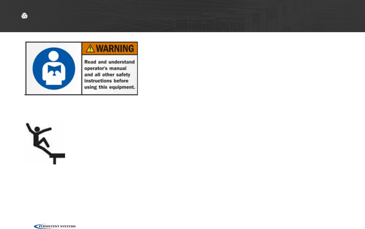
Handle Safely: ▶Falling while installing or removing equipment can cause serious injury.
▶If installing on a tower or any other tall locations, use proper lifting tech-
niques and wear proper protective equipment.
▶Tomber lors de l’installation ou de retirer l’équipment peut causer des
blessures graves.
▶Si vous installez sur une tour ou d’autres endroits de hauteur, utiliser des
techniques de levage appropriées et porter un équipment de protection
approprié.
© 2010 - 2018 Persistent Systems, LLC – All Rights Reserved 13
SAFETY
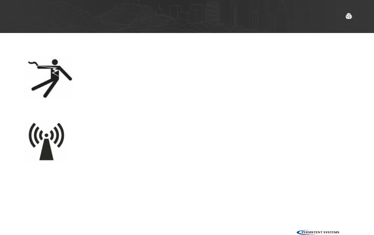
Electrical Shock
and Fires:
▶Understand and follow all local codes and regulations when installing elec-
trical equipment.
▶Only use approved battery and/or power supplies.
▶Comprendre et respecter tous les codes et règlements locaux lors de l’in-
stallation des équipements électriques.
▶Utilisez uniquement la batterie et les alimentations ou approuvé.
RF Exposure: ▶Prevent injury from exposure to high frequency fields.
▶See antenna separation instructions in the Compliance section of this man-
ual.
▶Do not operate with antenna removed. This can increase RF exposure
risks and/or damage the equipment.
▶Prévenir les blessures d l’exposition aux champs de haute fréquence.
▶Voir les instructions de séparation de l’antenne dans la section de la con-
formité de ce manuel.
▶Ne pas faire fonctionner avec antenne enlevé. Cela peut augmenter les
risques d’exposition aux radiofréquences et ou endommager l’équipe-
ment.

© 2010 - 2018 Persistent Systems, LLC – All Rights Reserved
14
SAFETY
CAUTION
DEVICE UTILIZES LITHIUM ION BATTERY
RISK OF EXPLOSION IF BATTERY IS REPLACED BY AN INCORRECT TYPE.
DISPOSE OF USED BATTERIES ACCORDING TO THE INSTRUCTIONS
----------------------------------------------------------------------
MISE EN GARDE
Dispositif utilise la batterie Ion Lithium
RISQUE D’EXPLOSION SI LA BATTERIE EST REMPLACE PAR UN TYPE INCORRECT.
Jetez les piles usagées selon
LES INSTRUCTIONS
Lithium Batteries Handling
▶Lithium ion batteries are defined as Class 9 dangerous goods by the IATA Dangerous Goods
Regulations.
▶Handle with care.
▶Do not use if package is damaged - it can cause fire.
Disposing of Used Batteries
▶Disposal should be done in accordance with applicable regulations, which vary from country to
country as well as by state and local governments. In most countries, trashing of used batteries
is forbidden and disposal can be done through non-profit organizations mandated by local au-

© 2010 - 2018 Persistent Systems, LLC – All Rights Reserved 15
SAFETY
thorities or organized by professionals.
▶Incineration of lithium cells and batteries by consumers is not recommended. Incineration
should be done at a properly permitted facility that can handle this waste.
---------------------------------------------------------------------------------------------------
Manipulation des batteries lithium
▶Les batteries au lithium-ion sont définis comme Classe 9 marchandises dangereuses par le Régle-
ment sur les marchandises dangereuses de l’IATA.
▶Manipuler avec soin.
▶Ne pas utiliser si l’emballage est dommage, il peut provoquer un incendie.
Mise au rebut des batteries usagées
▶L’élimination doit être effectuée conformément aux réglementations applicables, qui varient
d’un pays à l’autre ainsi que par les gouvernements d’État et locaux. Dans la plupart des pays
saccage des batteries usagées est interdit et l’élimination peut être fair par les organisations à
but non lucratif mandatés par les autorités locales ou organisées par des professionnels.
▶Incinération des dellules et batteries au lithium par les consommateurs est déconseillée. In-
cinération devrait être fait dans une installation dûment autorisée qui peut gérer ces déchets.
See Attached Battery Spec Sheet, MSDS, and compliance document for more information

© 2010 - 2018 Persistent Systems, LLC – All Rights Reserved
16
SUGGESTED ADDITIONAL HARDWARE
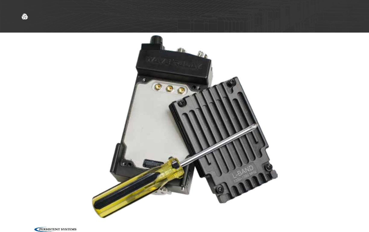
Suggested Additional Hardware
▶#1 Phillips Head Screwdriver: Used to attach/detach radio module
▶TPI Kit: Allows for antenna and RF cable matching
▶RF cable at various lengths (LMR-400): Allows for flexibility in antenna setup
▶Ethernet Cables
▶Ethernet Female-to-Female Extenders
▶HD Screen or TV with HDMI input: Displays Android™ computer interface and/or streaming
video
▶Laptop with Administrator Access: Used for device configuration
▶USB Thumb Drives: Used for software configuration storage and loading

© 2010 - 2018 Persistent Systems, LLC – All Rights Reserved 17
PHYSICAL SETUP: RF SETUP
What Will I Learn?
▶How to insert radio modules into the MPU5 chassis
▶How to attach antennas to the MPU5
→
Section A: RF Setup
Part I: Physical Setup
© 2010 - 2018 Persistent Systems, LLC – All Rights Reserved
18
PHYSICAL SETUP: RF SETUP

© 2010 - 2018 Persistent Systems, LLC – All Rights Reserved 19
PHYSICAL SETUP: RF SETUP
?How do I tell if my antennas and radio modules are compatible?
Find the part numbers on the antennas. Antenna part numbers are on a sticker wrapped around the base
of the antenna.
1
Find the part number on the radio module. The radio module part number is on a sticker on the back of
the radio module.
2
Each part number will begin with ANT- (antennas) or RF- (radio modules) followed by four (4) digits. The
first digit references the radio band of the part. Make sure that the first digit of the antennas and radio
module match.
3
!WARNING!: DO NOT use mismatched antennas and radio modules. This configuration will result in very
poor performance and/or damage to the device. If you do not have matching antennas and radio modules,
contact Persistent Systems.
!WARNING!: DO NOT switch radio modules while device is powered on. Power off device before changing
radio modules.
!WARNING!: the MPU5 is not IP68 rated when the radio module is not attached. Ensure you are in a dry,
dust-free environment before changing radio modules.
!WARNING!: User MUST refer to the Professional Installer – Compliance Section of this manual for ap-
proved antenna types. This warning applies only to RF-2100 with the FCC ID 2AG3J-RF-2100 and RF-5100 with
the FCC ID 2AG3J-RF-5100.
© 2010 - 2018 Persistent Systems, LLC – All Rights Reserved
20
PHYSICAL SETUP: RF SETUP
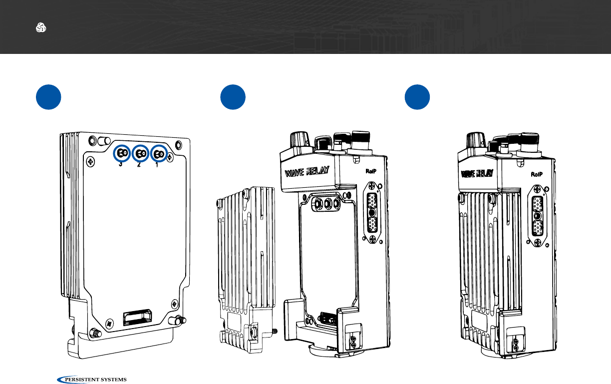
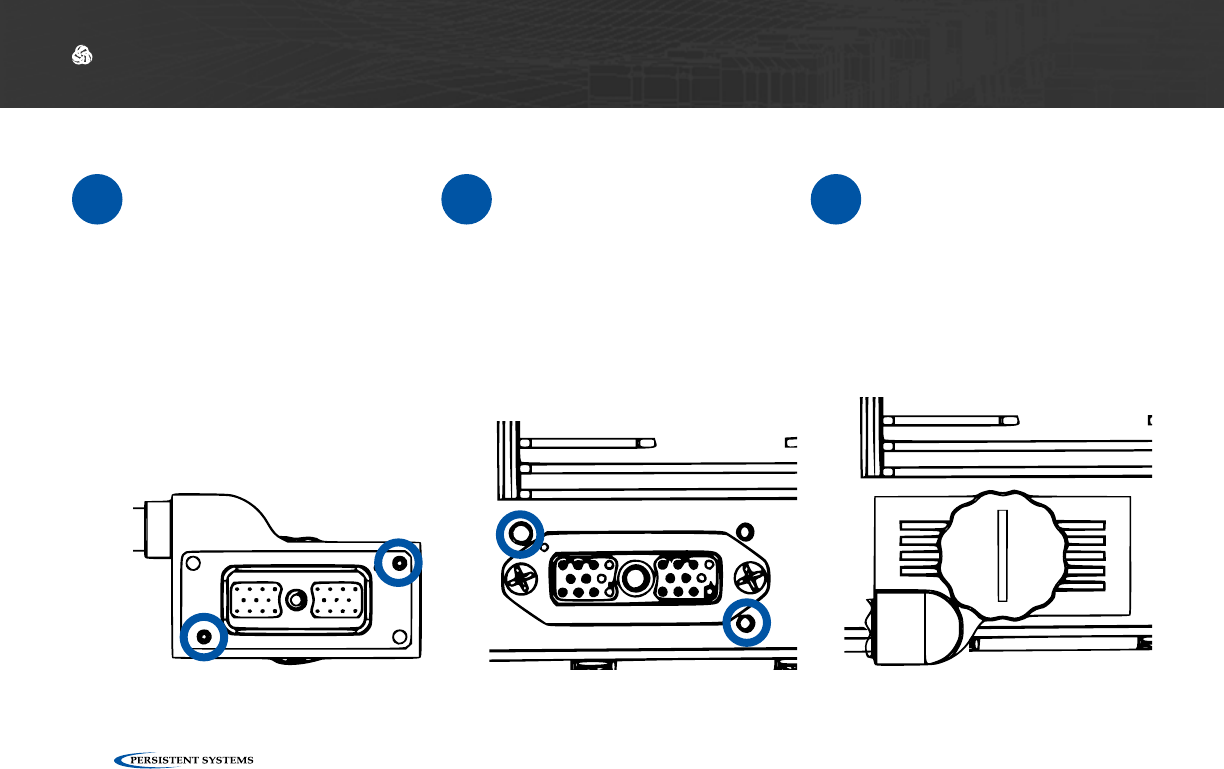
Inserting the Radio Module
1If there are rubber caps
on the radio module
contacts, remove them.
2Align the radio module
with the chassis. 3Apply even force and
press the radio module
into the chassis.
© 2010 - 2018 Persistent Systems, LLC – All Rights Reserved 21
PHYSICAL SETUP: RF SETUP
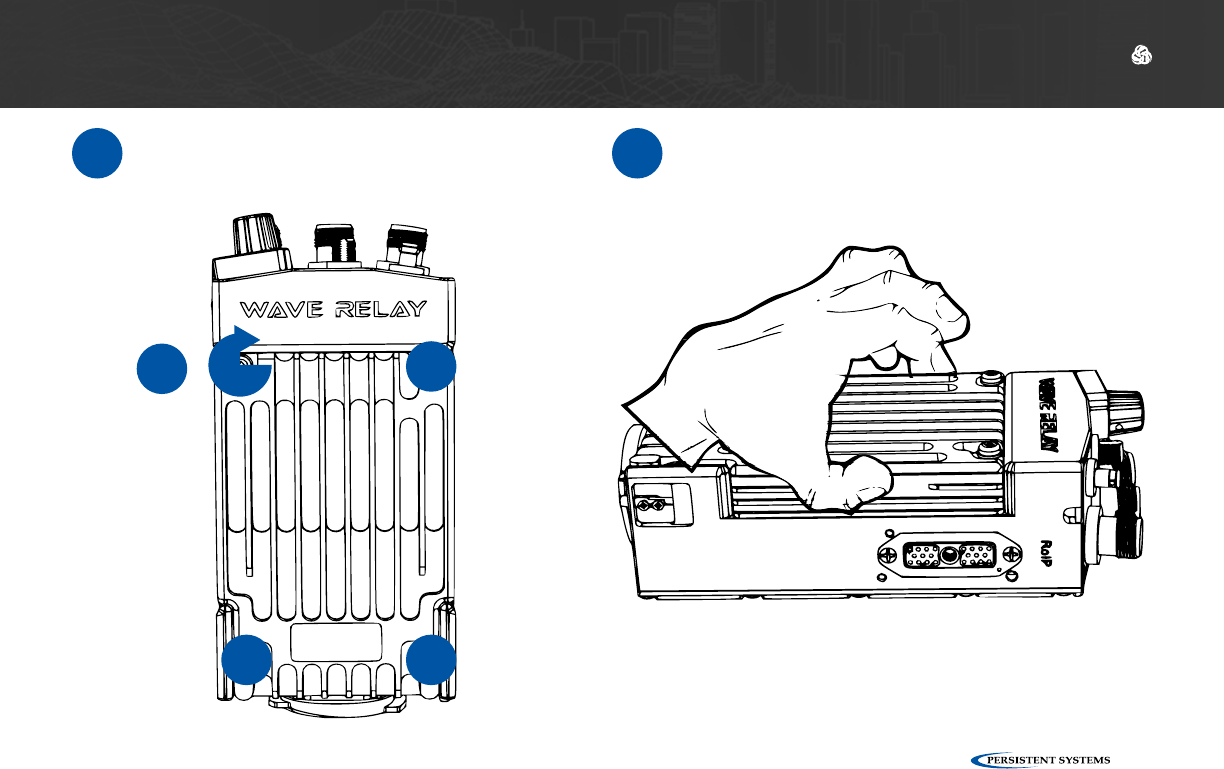
4Tighten screws clockwise in diagonal
order with a #1 Phillips Head screwdriver
until they stop (min. 4 in-lbs. of torque)
5Pull on the radio module to verify that it
is attached securely. Ensure there are no
gaps in between the radio module and the
MPU5 chassis.
1
2
3
4
© 2010 - 2018 Persistent Systems, LLC – All Rights Reserved
22
PHYSICAL SETUP: RF SETUP
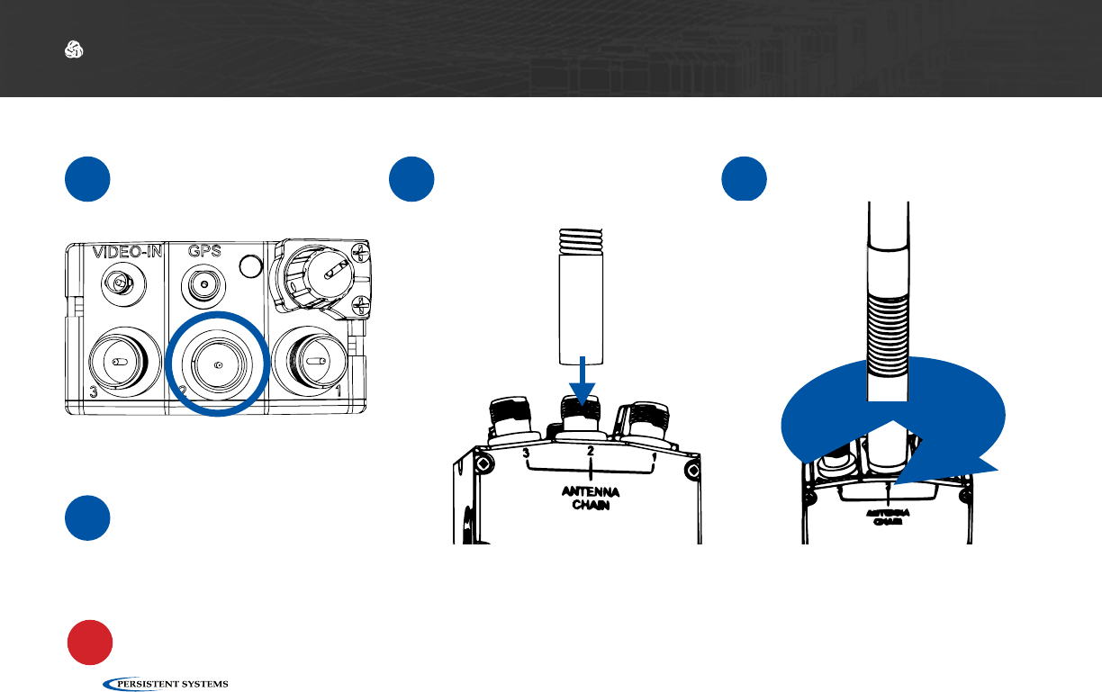
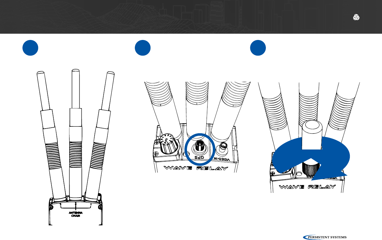
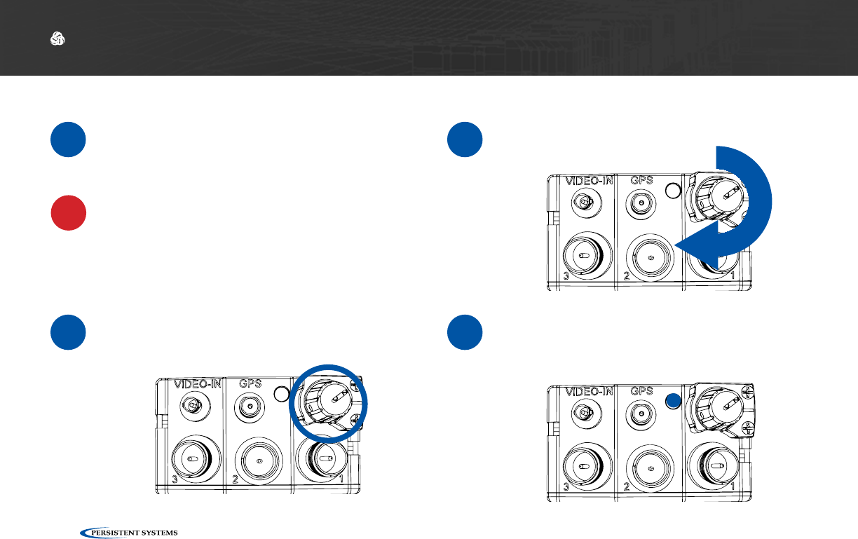
1Start with the middle
antenna port. 2Align the RF connector
on the antenna with the
RF connector on the unit.
3Twist the antenna clock-
wise until it is fully mated.
Connecting Antennas
▶You can use a TPI Kit and/or extra LMR-400 RF Cables to remote antennas away from the unit. This setup is particu-
larly useful for mounted or operations center configurations.
▶To operate in SISO mode, you only need to attach an antenna to the antenna port for the chain you want to use.
WARNING!: if you want to operate in SISO mode, unused antenna chains MUST be turned off (See p. 78).
Tips & Tricks
T
!
© 2010 - 2018 Persistent Systems, LLC – All Rights Reserved 23
PHYSICAL SETUP: RF SETUP
4Repeat Steps 1 - 3 for
the remaining two RF
antennas.
5Align the SMA connec-
tor on the GPS antenna
with the SMA connector
on the unit.
6Twist the antenna clock-
wise until it is fully mated.
© 2010 - 2018 Persistent Systems, LLC – All Rights Reserved
24
PHYSICAL SETUP: RF SETUP TROUBLESHOOTING
How do I ensure that the radio
module is aligned properly?
?
The three RF connectors on the radio module will
align with the three RF connectors on the chassis.
When aligned properly, the engraved writing on the
radio module will be facing the same direction as
the writing on the chassis.
What do I do if the radio module
won’t insert into the chassis?
?
Ensure that the radio module is aligned properly.
Ensure that the connectors on the radio module are
not bent.
Ensure that there are no foreign objects in any of
the connectors, on the bottom of the radio module,
or in the chassis well.
1
2
3
What do I do if the antennas won’t
screw onto the RF connectors?
?Ensure that you are using antennas with RP-TNC
Male connectors or an appropriate adapter from
your TPI kit.
Ensure that the connectors on both the unit and
antennas are not damaged.
Ensure that there are no foreign objects in any of
the connectors.
1
2
3
How do I tell if the antennas are
connected properly?
?When an antenna is mated properly, the threads on
the connector will not be visible. However, there
may be a small space between the antenna and the
chassis.
1

© 2010 - 2018 Persistent Systems, LLC – All Rights Reserved 25
PHYSICAL SETUP: RF SETUP
What Can I Do Now?
✓
▶Swap radio modules and antennas to change the RF band you are capable of operating on
▶Swap out broken radio modules and antennas
▶Setup hardware to receive GPS connectivity
▶Remote antennas away from the unit

© 2010 - 2018 Persistent Systems, LLC – All Rights Reserved
26
How can I use my old power accessories from previous Wave Relay products with my
MPU5?
?
You can use your MPU4 twist locking battery pack or BB batteries with the MPU5. You CANNOT use old battery
eliminators with the MPU5. Use only CBL-PWR-0001 or CBL-PWR-0002. You CANNOT power the MPU5 via
Power over Ethernet (PoE).
Will I lose all my settings if I remove power from my MPU5?
?If the MPU5 has been charged for 8 hours, it will retain unit settings for 30 days.
PHYSICAL SETUP: POWER
What Will I Learn?
▶How to connect a power source to the MPU5
▶How to power on the MPU5
→
Section B: Power
!WARNING!: the MPU5 requires an 8 hour charge in order to retain unit settings for 30 days.
© 2010 - 2018 Persistent Systems, LLC – All Rights Reserved 27
PHYSICAL SETUP: POWER
© 2010 - 2018 Persistent Systems, LLC – All Rights Reserved
28
PHYSICAL SETUP: POWER
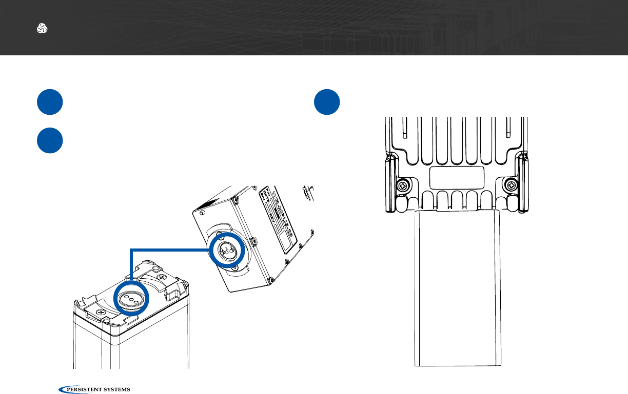
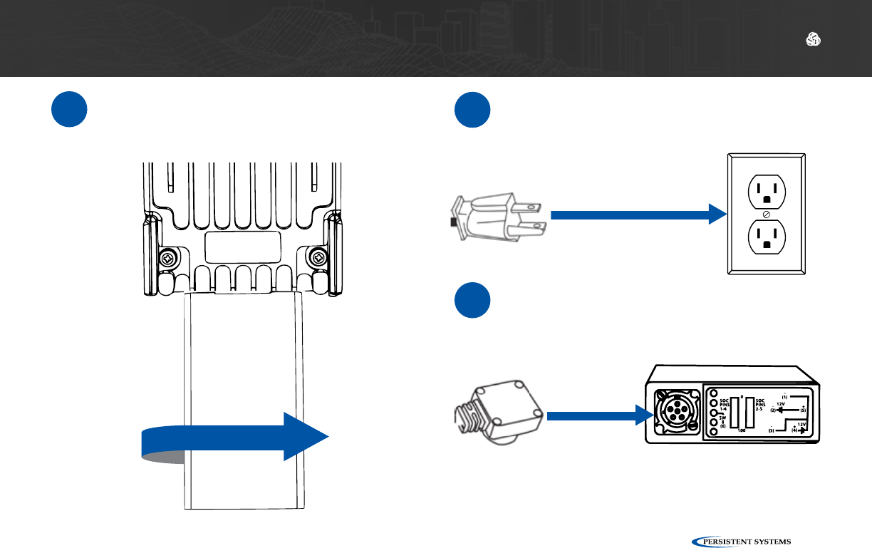
1If you are using a battery, make
sure that the battery is charged.
2Align the circular three pin connector on
the power source with the circular three
pin connector on the bottom of the MPU5.
3Push the connectors together. Make sure
the connector is seated properly.
Connecting Power
© 2010 - 2018 Persistent Systems, LLC – All Rights Reserved 29
PHYSICAL SETUP: POWER
4Twist clockwise 90°. You will hear a click
when it is locked. 5If you are using a Wall Battery Eliminator,
plug the standard wall plug into a stan-
dard wall outlet.
6If you are using a BB Battery Eliminator,
plug the BB plug into a BB Battery.
© 2010 - 2018 Persistent Systems, LLC – All Rights Reserved
30
PHYSICAL SETUP: POWER
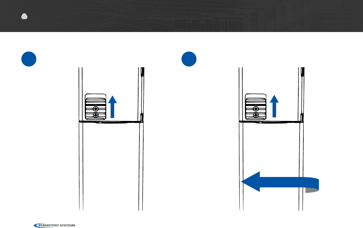
1Slide up the battery latch on the side of
the MPU5. 2Twist the battery counterclockwise until it
disconnects.
Removing Power

© 2010 - 2018 Persistent Systems, LLC – All Rights Reserved 31
PHYSICAL SETUP: POWER
What do I do if my power accessory will not fit the battery connector?
What do I do if my power accessory will not lock?
?
?
Ensure that no parts (pins, plates, etc.) on either connector are bent or damaged.
Ensure that the battery latch moves freely by sliding it up and down.
Ensure that there are no foreign objects in either connector.
Ensure that the battery latch is not stuck in the unlocked position.
1
1
2
2
© 2010 - 2018 Persistent Systems, LLC – All Rights Reserved
32
PHYSICAL SETUP: POWER
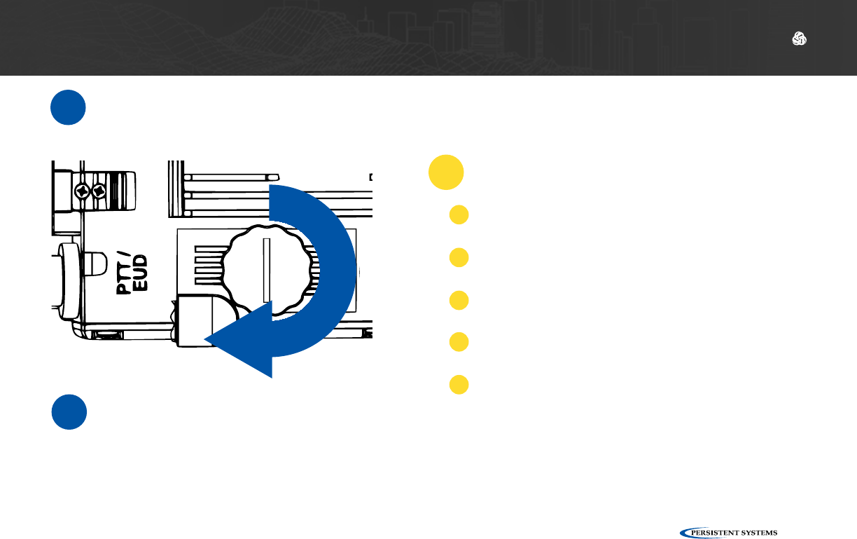
1Ensure that antennas, a radio module, and
an appropriate power source are connect-
ed.
4If the unit is powered and has turned on,
the LED on the top of the unit will glow
a color indicating unit status.
2Locate the Power Knob on the top of the
unit.
3Twist the Power Knob clockwise 1 click.
Powering On the Unit
!WARNING!: Antennas MUST be installed prior
to powering on the unit.

© 2010 - 2018 Persistent Systems, LLC – All Rights Reserved 33
PHYSICAL SETUP: POWER
What do I do if my Power Knob does
not rotate?
What do I do if the Power Knob does
not click when I twist it?
??
Make sure that you are twisting it in the correct
direction (clockwise). The Power Knob may be broken. Contact Persistent
Systems Support.
Make sure that no foreign objects are blocking the
rotation of the knob.
If the knob still does not rotate, it may be broken.
Contact Persistent Systems Support.
Ensure that the battery latch is not stuck in the
unlocked position.
11
2
3
2
LED Color Unit Status
Blue Booting
Yellow Running, no neighbors
Green Running, neighbors
Red Crypto Fail (No key or FIPS)
Orange Low Battery
Purple Loading Firmware
Quick Reference:

© 2010 - 2018 Persistent Systems, LLC – All Rights Reserved
34
PHYSICAL SETUP: SIDE CONNECTORS
What Can I Do Now?
What Will I Learn?
✓
▶Provide power to an MPU5 via a battery or standard wall socket
▶Power on/off the unit
▶Replace dead batteries
▶How to connect a cable to the MPU5 side connectors
→
Section C: Side Connector Cables
© 2010 - 2018 Persistent Systems, LLC – All Rights Reserved 35
PHYSICAL SETUP: SIDE CONNECTORS
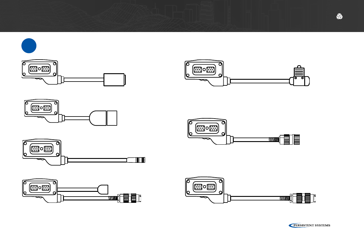
Parts List
≈
22-Pin to USB 2.0 Type A Receptacle
CBL-DATA-2003
22-Pin to Audio and Video Out
CBL-DATA-3002
22-Pin to RJ45 Receptacle
CBL-DATA-2001
22-Pin to U-329
CBL-AUD-0001
22-Pin to U-328
CBL-AUD-0002
22-Pin to U94
CBL-AUD-0003
22-Pin to 6-Pin Push Pull USB Tether
CBL-DATA-2004
© 2010 - 2018 Persistent Systems, LLC – All Rights Reserved
36
PHYSICAL SETUP: SIDE CONNECTORS
1The 22-Pin connector on
every cable is keyed so
that it will only attach to
a compatible side con-
nector. If a cable can
attach to multiple side
connectors, it is keyed
(or not keyed) so that it
will attach to all compati-
ble side connectors.
2To connect a cable to a
side connector, locate
the appropriate side
connector.
3Align the key pins on
the 22-Pin connector
with the key holes on
the case. Push the key
pins into the key holes.
Connecting a Cable to a Side Connector
© 2010 - 2018 Persistent Systems, LLC – All Rights Reserved 37
PHYSICAL SETUP: SIDE CONNECTORS
4
5
Twist the thumbscrew clockwise to attach
the cable to the device.
Ensure that the cable is firmly attached and
the connector is sitting flush with the case.
Ensure that there are no foreign objects in the
thumbscrew or side connector.
4
Ensure that the cable connector is flush with the
case.
5
What do I do if the cable won’t mate
with the side connector?
?
Ensure that you are trying to connect the cable to
the correct side connector.
1
Ensure that you are aligning the key pin properly
and the cable is not upside down.
2
Ensure that no parts of the thumbscrew and the
side connector are bent or damaged.
3

© 2010 - 2018 Persistent Systems, LLC – All Rights Reserved
38
PHYSICAL SETUP: SIDE CONNECTORS
Quick Reference:
Part Number Description Side Connec-
tor(s)
Uses
CBL-DATA-2001 22-Pin to RJ45 Receptacle DATA Connects to a standard RJ45 Ethernet cable. Use
this cable to connect the unit to a computer for
configuration.
CBL-DATA-2003 22-Pin to USB 2.0 Type A
Female
PTT/EUD,
DATA, RoIP
Connects USB accessories via a standard USB A
port.
CBL-DATA-2004 22-Pin to 6-Pin Push Pull
Android™ USB
PTT/EUD,
DATA, RoIP
Connects an Android™ EUD or Screen
CBL-DATA-2005 22-Pin to DB9 Serial Socket PTT/EUD,
DATA, RoIP
Connects serial devices via a DB9 socket
CBL-DATA-2007 22-Pin to RJ45 Receptacle
and USB 2.0 Type A Male
DATA Connects to USB devices via a standard USB A
plug and to a standard RJ45 Ethernet cable
CBL-DATA-2009 22-Pin to RJ45 Flying Leads DATA Flying leads for custom Ethernet integration (72”)
CBL-DATA-2010 22-Pin to RJ45 Flying Leads DATA Flying leads for custom Ethernet integration (18”)
CBL-DATA-3002 22-Pin to Audio and Video
Out
PTT/EUD Connects to a standard HDMI cable to display
video on a TV or Monitor and connects to a
speaker box or headset.
CBL-AUD-0001 22-Pin to U-329 RoIP Connect the unit to a Legacy Radio via a U-329
connector.

© 2010 - 2018 Persistent Systems, LLC – All Rights Reserved 39
PHYSICAL SETUP: SIDE CONNECTORS
CBL-AUD-0002 22-Pin to U-328 PTT/EUD Connects to a headset via a U-328 connector.
CBL-AUD-0007 22-Pin to Audio and USB
2.0 Type A Female
PTT/EUD Connects USB accessories via a standard USB A
port and an audio accessory via a U-328 connec-
tor
CBL-AUD-2009 22-Pin to Audio and 6-Pin
Push Pull Android™ USB
PTT/EUD Connects an Android™ EUD or Screen and an
audio accessory via a U-328 connector
What Can I Do Now?
✓
▶Identify which cable you need for your configuration
▶Identify which side connector your cables attach to
▶Connect a cable to a side connector
Refer to the MPU5 Product Catalog for more information on MPU5 cables. If you still have ques-
tions, contact Persistent Systems.
© 2010 - 2018 Persistent Systems, LLC – All Rights Reserved
40
SOFTWARE SETUP: MANAGEMENT COMPUTER
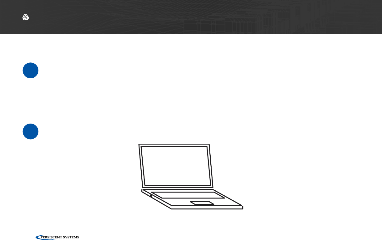
What Will I Learn?
▶How to configure your computer to be able to communicate with an MPU5
→
Section A: Configuring the Management Computer
Part II: Software Setup
Parts List
≈
Management Computer with Administrator Access & Ethernet Port

© 2010 - 2018 Persistent Systems, LLC – All Rights Reserved 41
SOFTWARE SETUP: MANAGEMENT COMPUTER
!IMPORTANT INFORMATION!:
▶To communicate with an MPU5, the computer must have an IP address in the same subnet
mask as the MPU5’s IP address.
▶For example, with a subnet mask of 255.255.255.0, the computer and MPU5 will be able
to communicate if they share the same first three numbers in their respective IP addresses
(e.g. 10.3.1.10 and 10.3.1.254).
▶If the computer and MPU5 do not share a subnet mask, the computer and MPU5 will not
be able to communicate.
▶If either the computer or MPU5 do not have an IP address in the same subnet mask, the
computer and MPU5 device will not be able to communicate.
© 2010 - 2018 Persistent Systems, LLC – All Rights Reserved
42
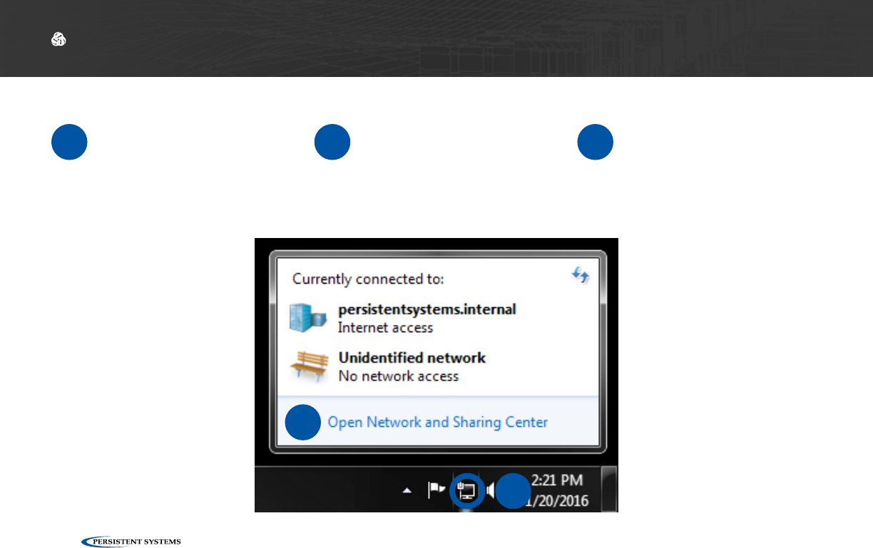
SOFTWARE SETUP: MANAGEMENT COMPUTER
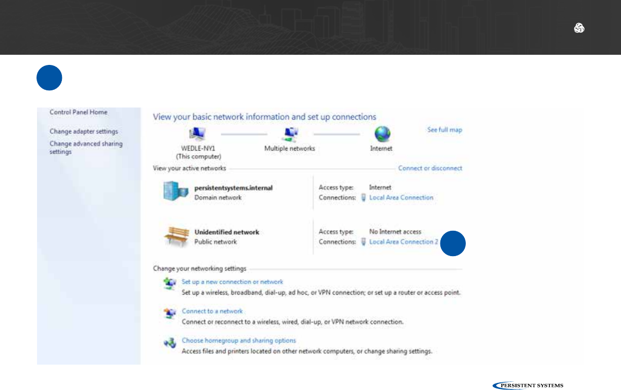
1Locate the Network
icon at the bottom right
of the taskbar.
2Right click the Network
icon. 3Click Open Network
and Sharing Center.
Configuring the Management Computer (Windows)
2
3
© 2010 - 2018 Persistent Systems, LLC – All Rights Reserved 43
SOFTWARE SETUP: MANAGEMENT COMPUTER
4Click Local Area Connection 2.
4
© 2010 - 2018 Persistent Systems, LLC – All Rights Reserved
44
SOFTWARE SETUP: MANAGEMENT COMPUTER
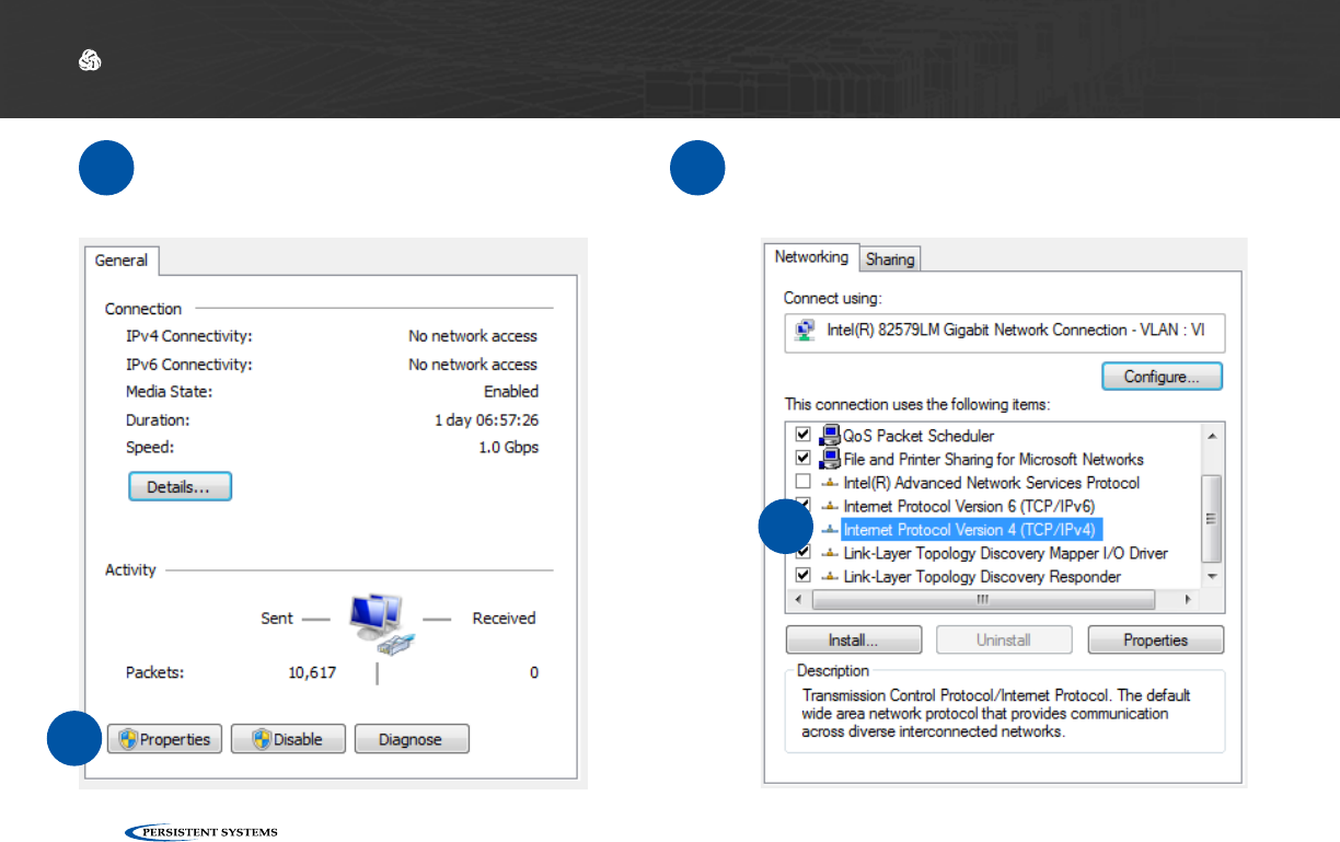
5Click Properties.6Select Internet Protocol Version 4 (TCP/
IPv4) and ensure that it is highlighted as
pictured.
6
5
© 2010 - 2018 Persistent Systems, LLC – All Rights Reserved 45
SOFTWARE SETUP: MANAGEMENT COMPUTER
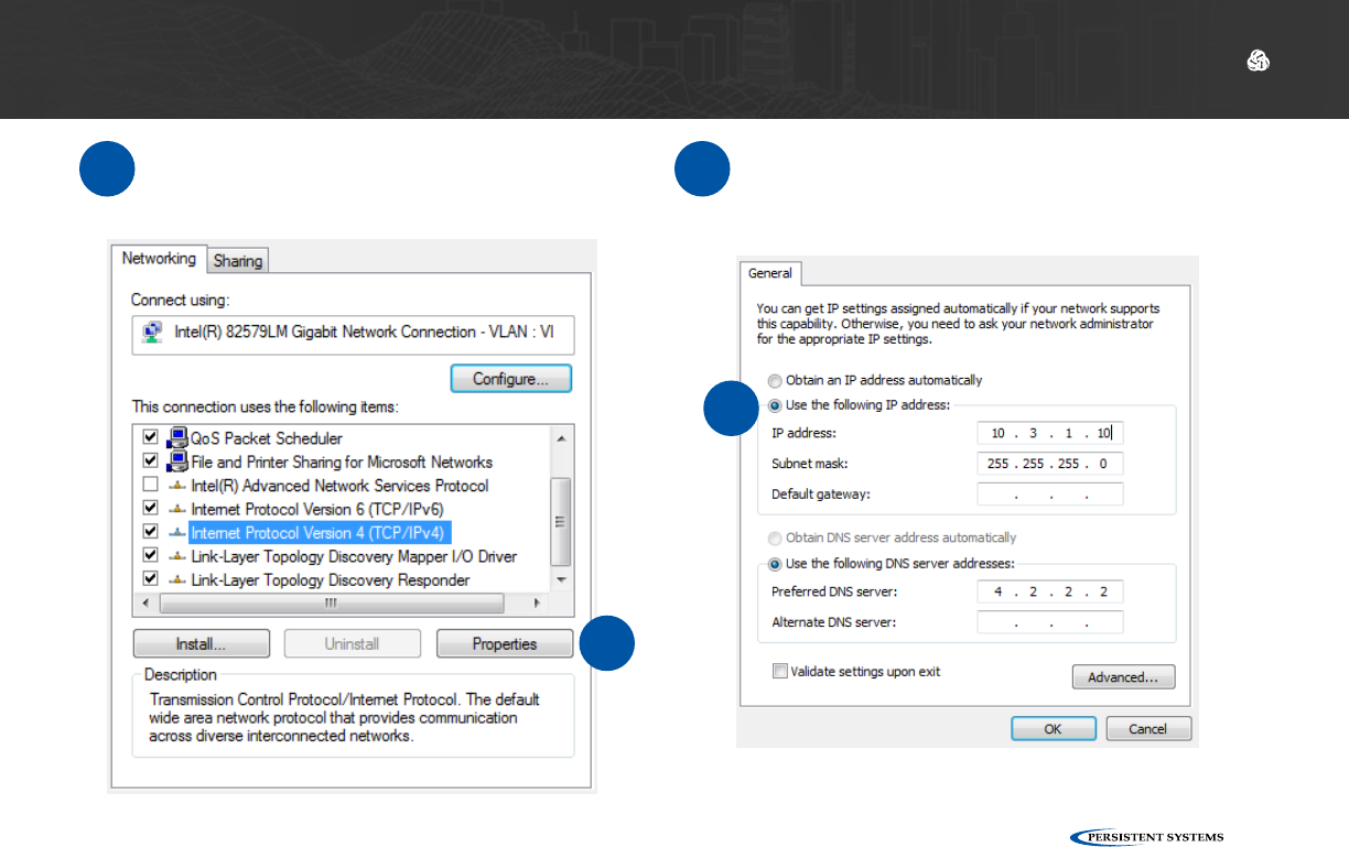
8Click Use the following IP address.
7Click Properties.
7
8
© 2010 - 2018 Persistent Systems, LLC – All Rights Reserved
46
SOFTWARE SETUP: MANAGEMENT COMPUTER
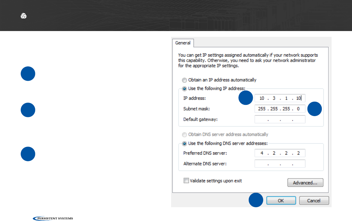
9Enter 10.3.1.10 into the
IP address field.
10 Enter 255.255.255.0
into the Subnet mask
field.
Click OK.
11
9
10
11

© 2010 - 2018 Persistent Systems, LLC – All Rights Reserved 47
SOFTWARE SETUP: MANAGEMENT COMPUTER
Your computer is now properly configured to connect to the MPU5.
12

© 2010 - 2018 Persistent Systems, LLC – All Rights Reserved
48
1Open the command line.
2Type:
sudo ifcong eth0 10.4.1.10/24
Configuring the Management Computer (Linux)
3Type:
sudo ip addr add 10.3.1.10/24 dev eth0
What Can I Do Now?
✓
▶Configure computers to be able to communicate with Wave Relay® devices.
▶Have a computer that is able to configure a Wave Relay® device.
SOFTWARE SETUP: MANAGEMENT COMPUTER
© 2010 - 2018 Persistent Systems, LLC – All Rights Reserved 49
SOFTWARE SETUP: MANAGEMENT COMPUTER
What Will I Learn?
▶How to physically connect the MPU5 to the Management Computer
→
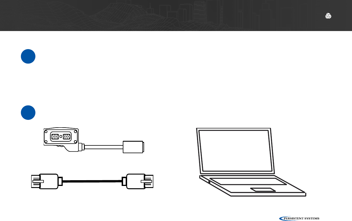
Parts List
≈
22-Pin to RJ45 Receptacle
CBL-DATA-2001
Properly Configured Management Computer with Ethernet PortStandard RJ45 Ethernet Cable
Section B: Connecting the MPU5 to the Management Computer
© 2010 - 2018 Persistent Systems, LLC – All Rights Reserved
50
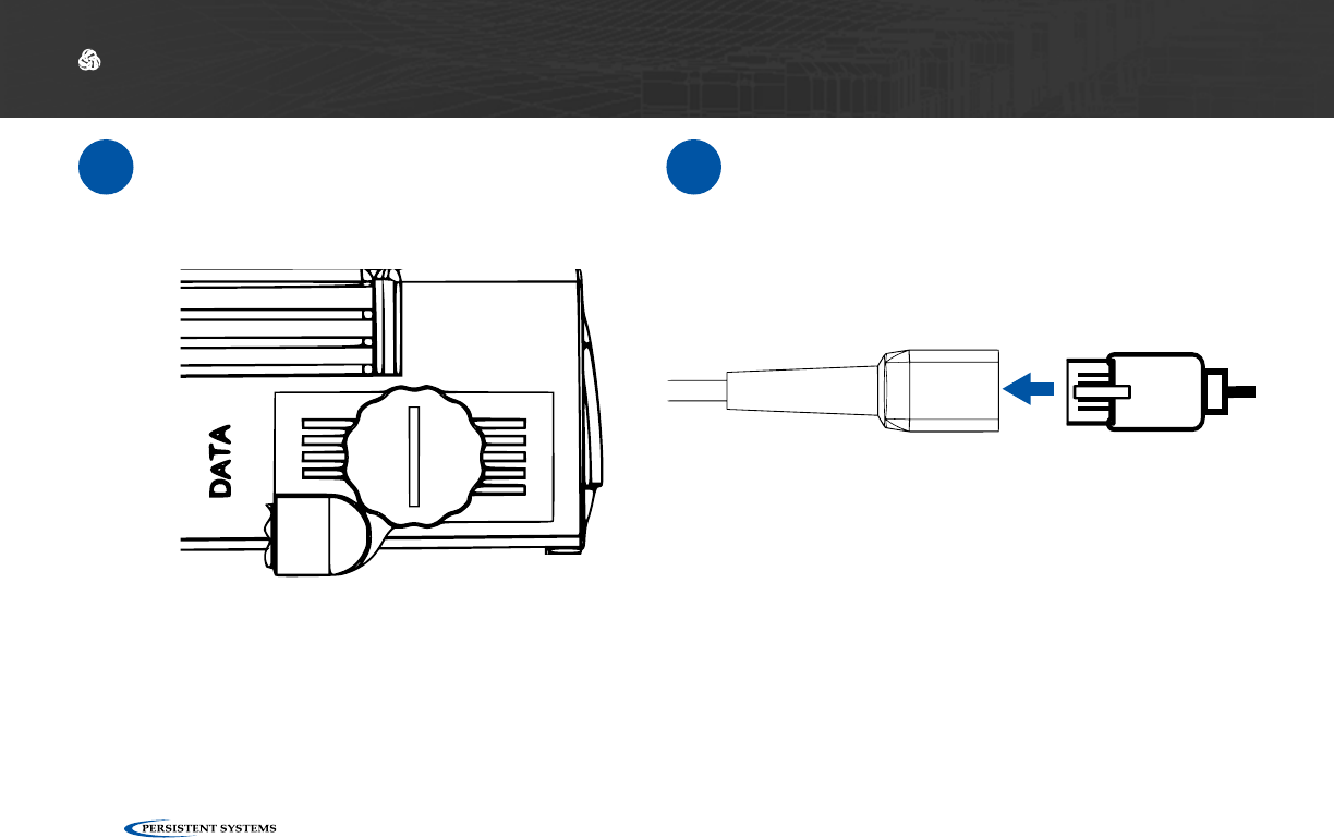
1Connect CBL-DATA-2001 to the DATA
side connector on the MPU5. 2Plug one end of the standard RJ45 Ether-
net cable into the Ethernet receptacle on
CBL-DATA-2001.
SOFTWARE SETUP: MANAGEMENT COMPUTER
© 2010 - 2018 Persistent Systems, LLC – All Rights Reserved 51
SOFTWARE SETUP: MANAGEMENT COMPUTER
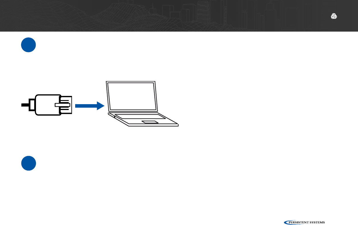
3Plug the other end of the standard RJ45 Ethernet cable into an Ethernet port on the Man-
agement Computer.
What Can I Do Now?
✓
▶Connect an MPU5 to a computer for configuration
© 2010 - 2018 Persistent Systems, LLC – All Rights Reserved
52
SOFTWARE SETUP: WEB MANAGEMENT INTERFACE
What Will I Learn?
▶How to access the Web Management Interface to configure the MPU5
→
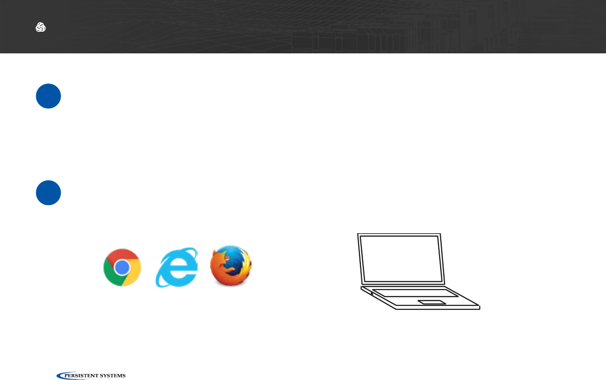
Parts List
≈
Web Browser (Internet Explorer 7+,
Firefox 3+, or Chrome
Management Computer with properly configured IP ad-
dress and subnet mask & Ethernet Port
Section C: Accessing the Web Management Interface
© 2010 - 2018 Persistent Systems, LLC – All Rights Reserved 53
SOFTWARE SETUP: WEB MANAGEMENT INTERFACE
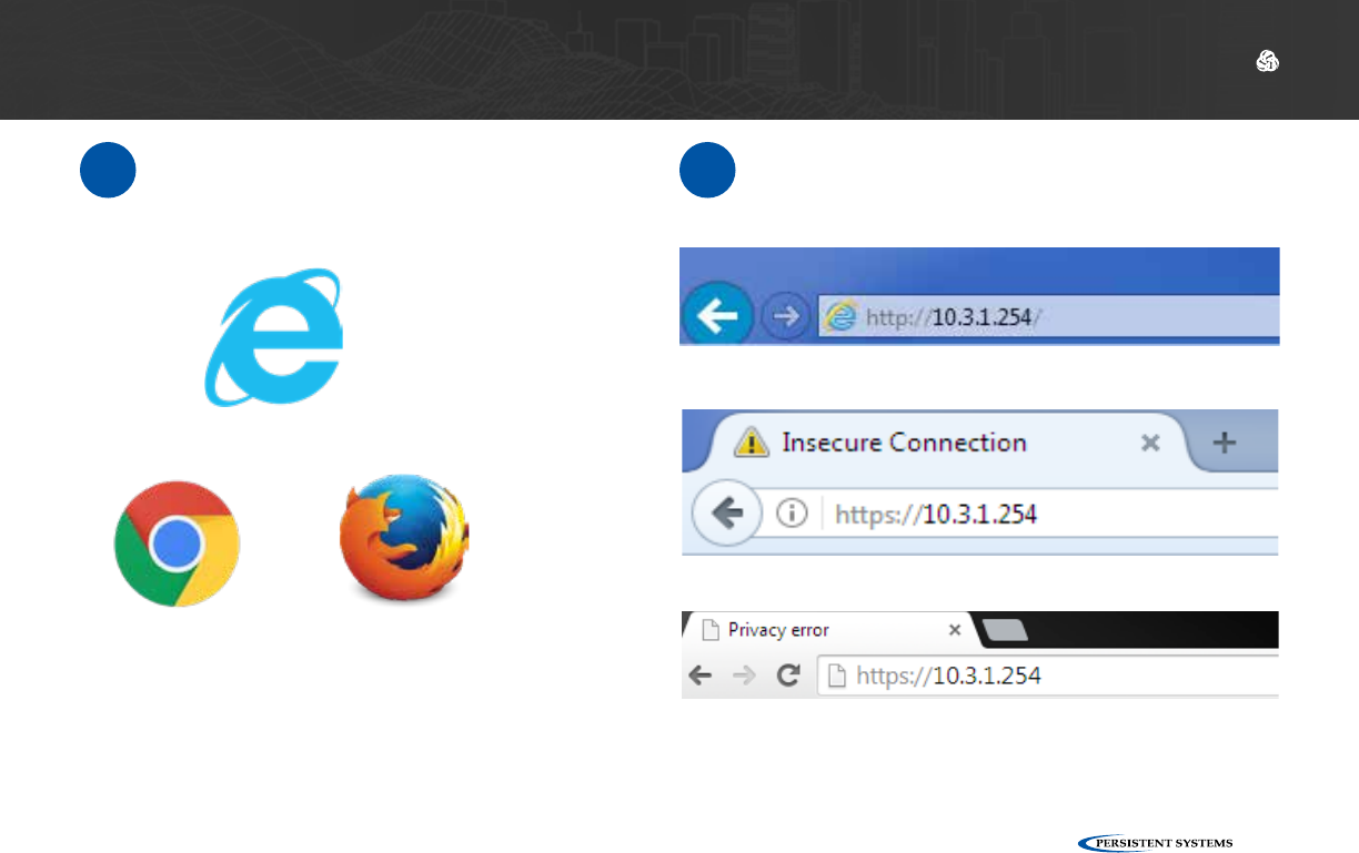
1Open the web browser
Microsoft Internet Explorer 7+
Microsoft Internet Explorer 7+
Google Chrome
Google Chrome
Mozilla Firefox 3+
Mozilla Firefox 3+
2In the address bar, type https://10.3.1.254
then press the Enter key.
© 2010 - 2018 Persistent Systems, LLC – All Rights Reserved
54
SOFTWARE SETUP: WEB MANAGEMENT INTERFACE
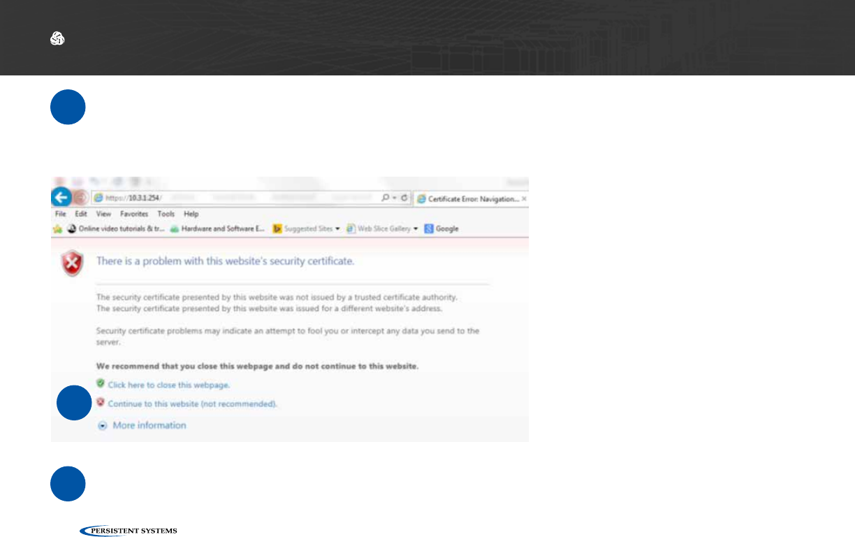
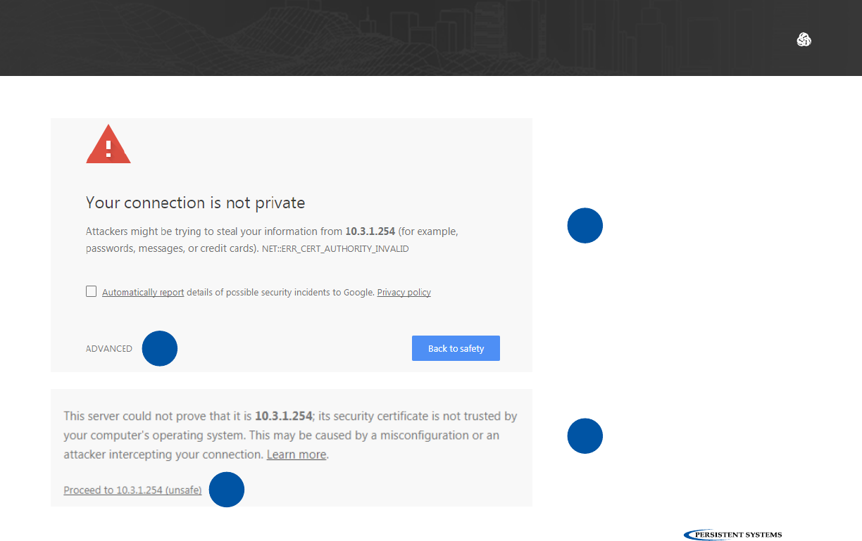
3
a
The web browser will ask you to accept a security certificate.
In Internet Explorer:
Click Continue to this website (not recommended)
a
© 2010 - 2018 Persistent Systems, LLC – All Rights Reserved 55
SOFTWARE SETUP: WEB MANAGEMENT INTERFACE
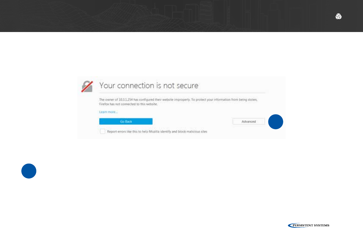
b
In Firefox:
Click I Understand the Risks
b
© 2010 - 2018 Persistent Systems, LLC – All Rights Reserved
56
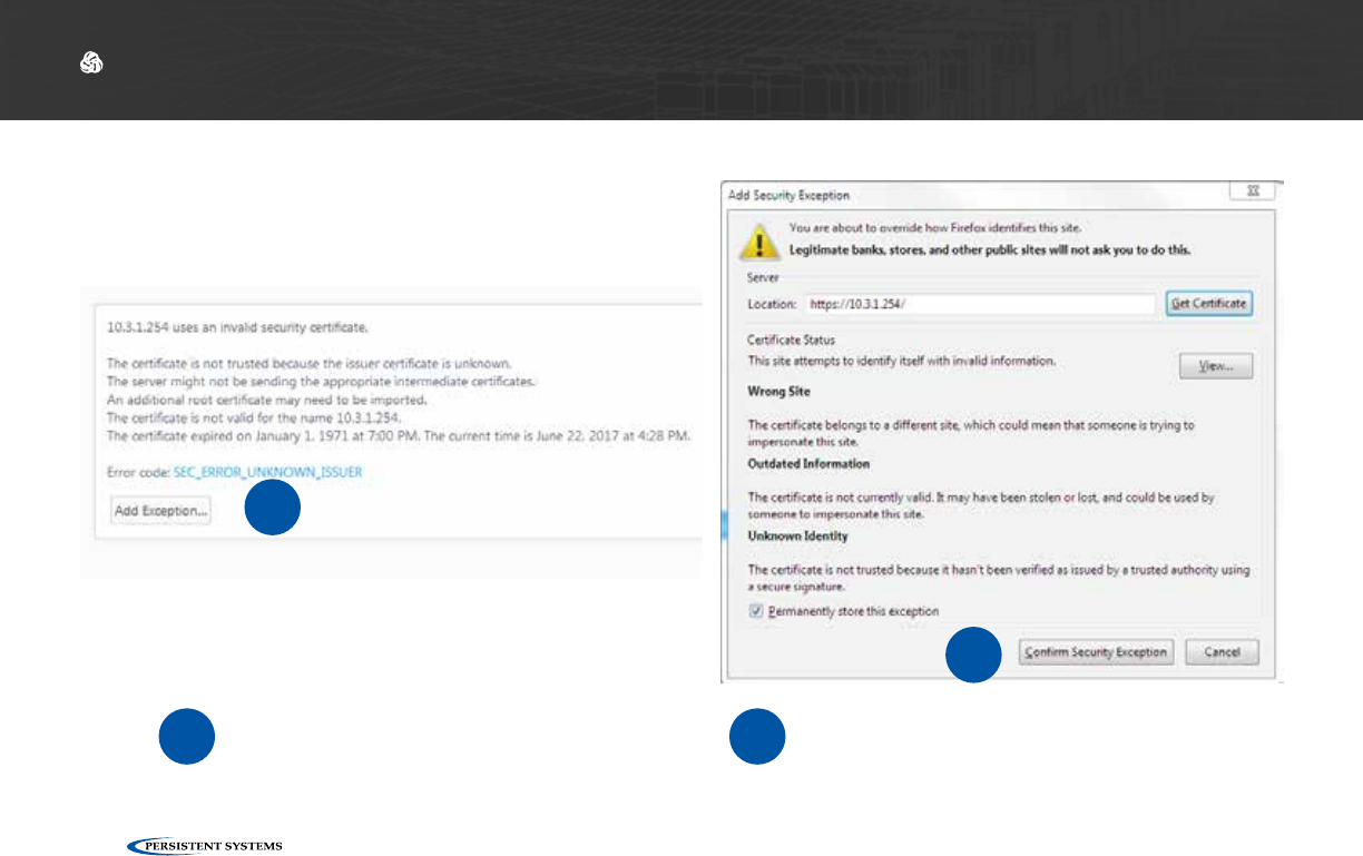
SOFTWARE SETUP: WEB MANAGEMENT INTERFACE
Click Add Exception Click Confirm Security Exceptioncd
d
c
© 2010 - 2018 Persistent Systems, LLC – All Rights Reserved 57
SOFTWARE SETUP: WEB MANAGEMENT INTERFACE
In Chrome:
Click Advanced
Click Proceed to
10.3.1.254 (unsafe)
e
f
f
e
© 2010 - 2018 Persistent Systems, LLC – All Rights Reserved
58
SOFTWARE SETUP: WEB MANAGEMENT INTERFACE
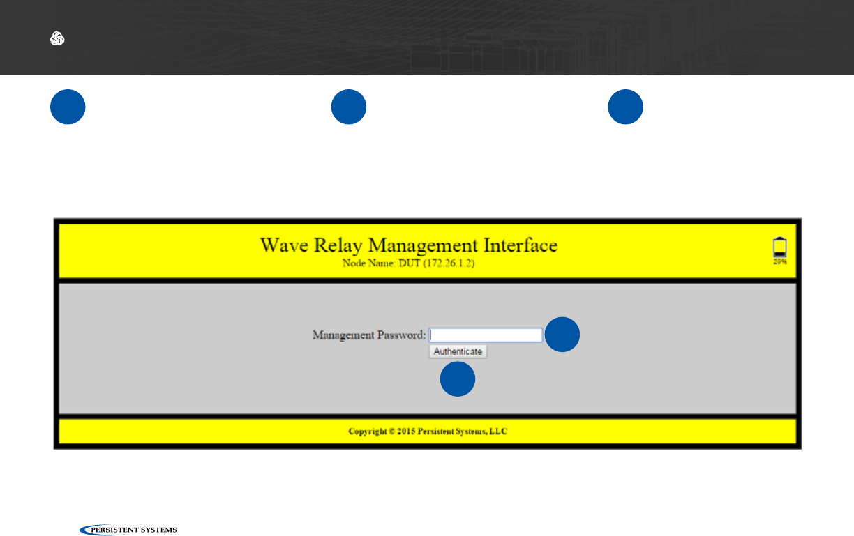
4Wait for the Web Man-
agement Interface page
to load
5In the Management
password field, type
password
6Click Authenticate.
5
6

© 2010 - 2018 Persistent Systems, LLC – All Rights Reserved 59
SOFTWARE SETUP: WEB MANAGEMENT INTERFACE
Why does the Security Exception Page or the Web Management Interface page not
load?
?
Verify that you configured the Management Com-
puter IP address and subnet mask properly.
1Ensure that you are using a compatible web
browser.
4
Ensure that all cables are connected properly
2Reboot the node.5
Ensure that you are accessing the correct manage-
ment IP address (10.3.1.254).
3
What Can I Do Now?
✓
▶Access the Web Management Interface for any node you connect to your computer.

© 2010 - 2018 Persistent Systems, LLC – All Rights Reserved
60
SOFTWARE SETUP: SECURITY KEY
Security Key
▶How to set the security key and crypto mode on an MPU5
What Will I Learn?
→
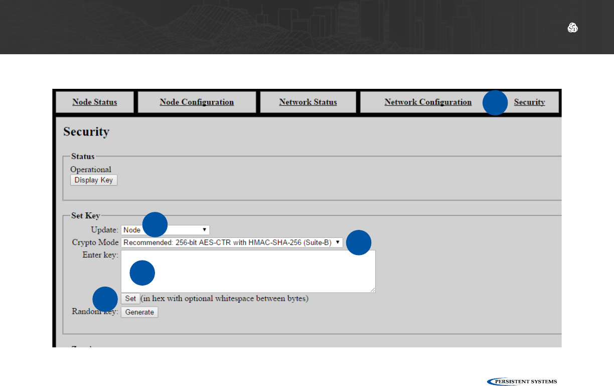
1Click the Security tab. 2In the Set Key section, locate the Update
drop down menu. Select Node.
3In the Crypto Mode drop down menu,
select the desired Crypto Mode.
Note: All nodes must have the same Crypto
Mode in order to communicate.
4In the Enter key field, type the desired
security key or click the Generate button
to generate a random key.
65 Copy and paste the security key to a
text file in a secure place on the Man-
agement Computer.
Click the Set button to set the key for the
node.
Section D: Basic Network Setup
© 2010 - 2018 Persistent Systems, LLC – All Rights Reserved 61
SOFTWARE SETUP: SECURITY KEY
1
23
4
6

© 2010 - 2018 Persistent Systems, LLC – All Rights Reserved
62
SOFTWARE SETUP: SECURITY KEY
What Can I Do Now?
✓
▶Set or change the security key and crypto mode for a single node
▶Generate a random security key
▶Save a security key in a text file to copy to other nodes
Assigning IP Address and Interface Names
What Will I Learn?
▶How to set and change the Node Name and IP Address of a node
→
© 2010 - 2018 Persistent Systems, LLC – All Rights Reserved 63
SOFTWARE SETUP: ASSIGNING IP ADDRESS AND INTERFACE NAMES
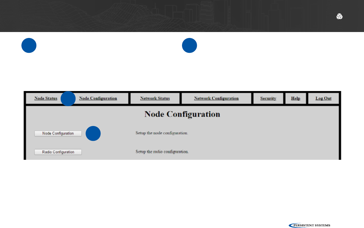
1Click the Node Configuration tab. 2Click the Node Configuration button.
1
2
© 2010 - 2018 Persistent Systems, LLC – All Rights Reserved
64
SOFTWARE SETUP: ASSIGNING IP ADDRESS AND INTERFACE NAMES
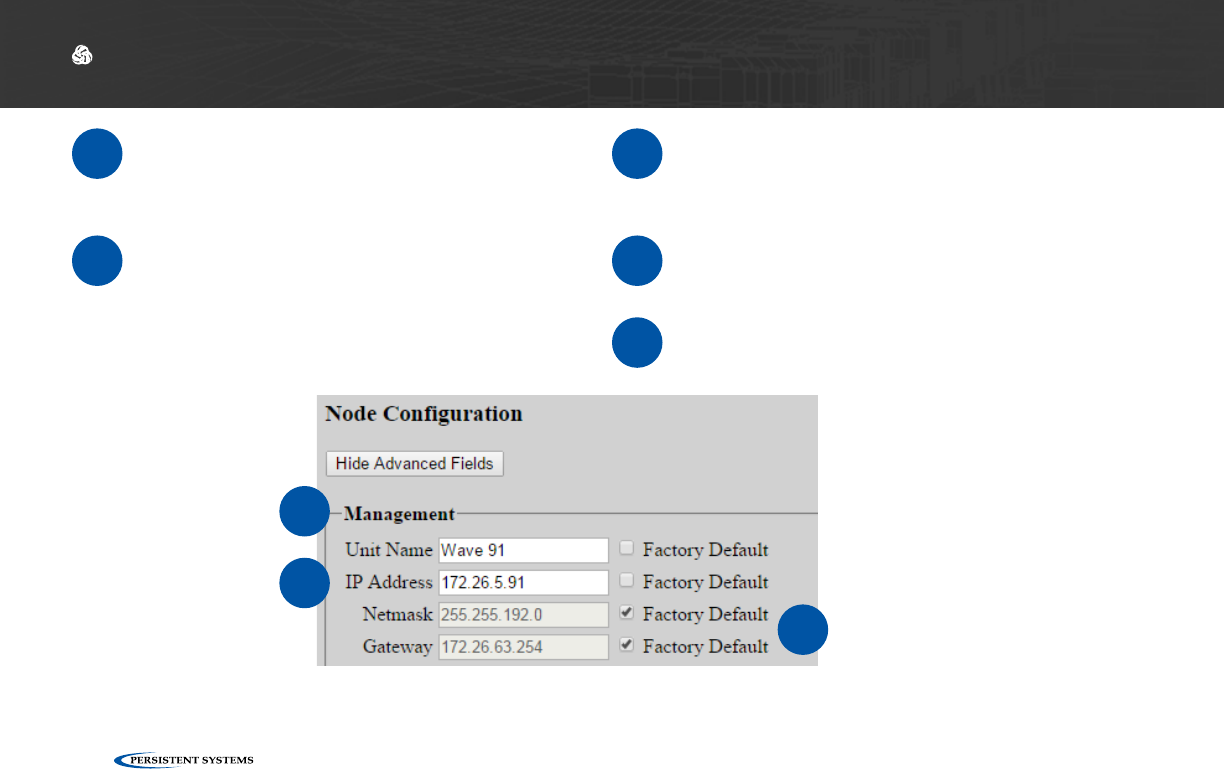
3In the Management section, find the Node
Name field and enter the desired Node
Name.
4In the IP Address field, enter the desired
IP Address. 6Scroll to the bottom of the page and click
the Save & Reconfigure Unit button.
5Enter a Netmask and Gateway, if re-
quired. Otherwise, check the Factory
Default box.
7Wait for the page to reload.
3
4
5
© 2010 - 2018 Persistent Systems, LLC – All Rights Reserved 65
SOFTWARE SETUP: REBOOTING AN INDIVIDUAL NODE
What Can I Do Now?
✓
▶Access the Node Configuration page for an individual node
▶Set the Node Name and IP Address of a node to fit the node into your IP scheme and identify
the node in status functions
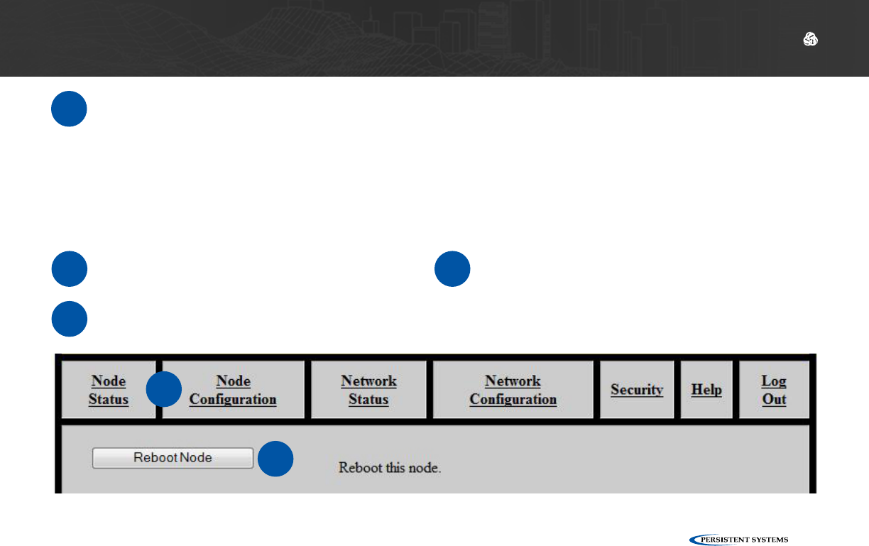
Rebooting an Individual Node
1Log into the node.
2Click the Node Configuration tab.
3Scroll down and click the Reboot
Node button.
2
3
© 2010 - 2018 Persistent Systems, LLC – All Rights Reserved
66
SOFTWARE SETUP: NETWORK NODE LIST
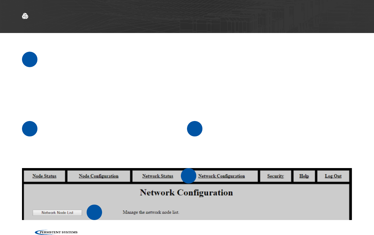
Network Node List
What Will I Learn?
▶How to add and remove nodes from the Management Node List
▶How to push the Management Node List to all nodes in your network
→
1Click the Network Configuration tab. 2Click Network Node List.
1
2
© 2010 - 2018 Persistent Systems, LLC – All Rights Reserved 67
SOFTWARE SETUP: NETWORK NODE LIST
The Network Node List creates a list of nodes for Network Status and Network Configuration
functions. Those functions will ONLY operate on nodes that are in the Network Node List.
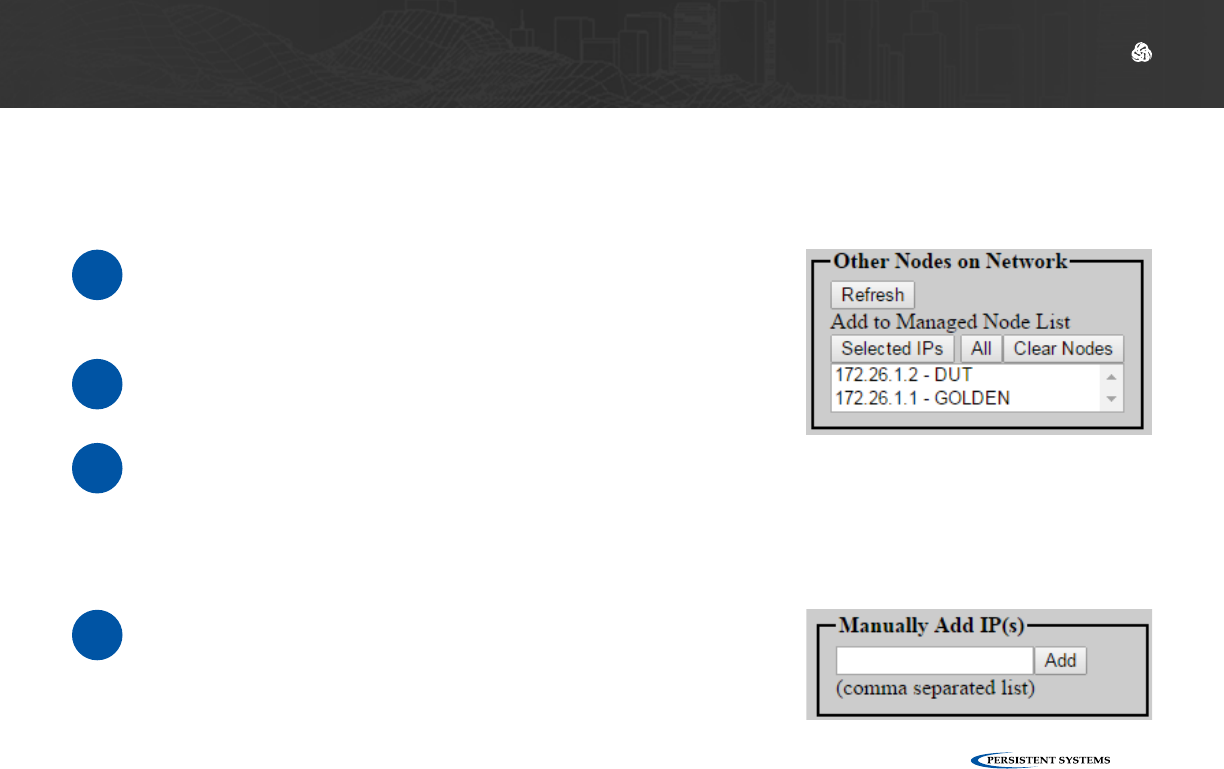
Adding Nodes to the Network Node List
1Ensure that all your nodes are powered on and that you
have configured their IP addresses and node names.
These will appear in the Other Nodes on Network box.
3Click All to add all nodes in the box to the Network Node
List. Alternatively, select one or more nodes and click
Selected IPs to add those nodes to the Network Node
List. Hold the shift key or ctrl key while clicking to select
multiple nodes.
4Nodes can be added manually as well. Enter a comma
separated list of all IP addresses to add in the Manually
Add IP(s) box, then click Add.
2Click Refresh if all nodes do not appear.
© 2010 - 2018 Persistent Systems, LLC – All Rights Reserved
68
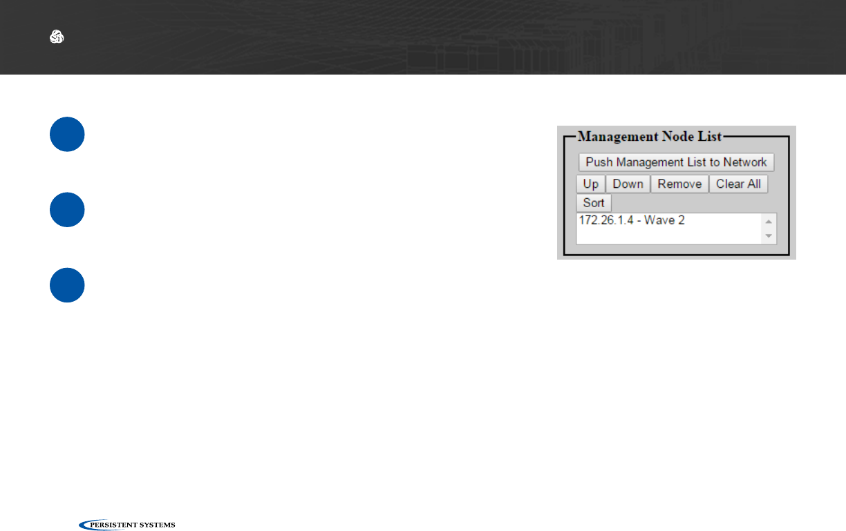
Managing the Network Node List
1After you add nodes to the Network Node List, they will
appear in the box on the left of the page.
3Click Push Management List to Network to copy the
Network Node List to all the nodes in the Network Node
List. This will ensure that Network Status and Network
Configuration functions will work properly on all nodes in
the network.
2Use the Up, Down, Remove, Clear All, and Sort buttons
to reorder or delete nodes from the Network Node List.
Note: ensure that all nodes are turned on and have the same radio settings (i.e. they are able to be
contacted). If nodes are not able to be contacted, they will not receive the Network Node List.
Note: remember to add new nodes to the Network Node List when you are expanding your net-
work.
SOFTWARE SETUP: NETWORK NODE LIST

© 2010 - 2018 Persistent Systems, LLC – All Rights Reserved 69
What Can I Do Now?
✓
▶Add new nodes to the Network Node List
▶Remove nodes from the Network Node List
▶Synchronize the Network Node List between all nodes on your network
SOFTWARE SETUP: NETWORK NODE LIST
© 2010 - 2018 Persistent Systems, LLC – All Rights Reserved
70
TESTING CONNECTIVITY: NEIGHBOR NODE STATUS
What Will I Learn?
▶How to tell if nodes are connected
▶How to see the connection strength between Neighbor Nodes
▶Neighbor Nodes are nodes connected without hops through other nodes
▶How to test bandwidth between nodes
→
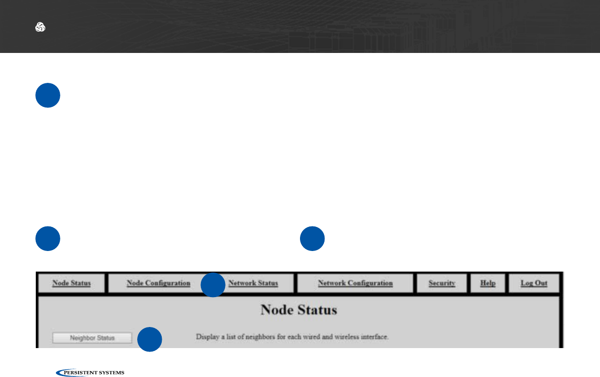
Check Neighbor Node Status
Part III: Testing Connectivity
1Click the Network Status tab. 2Click the Neighbor Status button.
1
2
© 2010 - 2018 Persistent Systems, LLC – All Rights Reserved 71
TESTING CONNECTIVITY: NEIGHBOR NODE STATUS
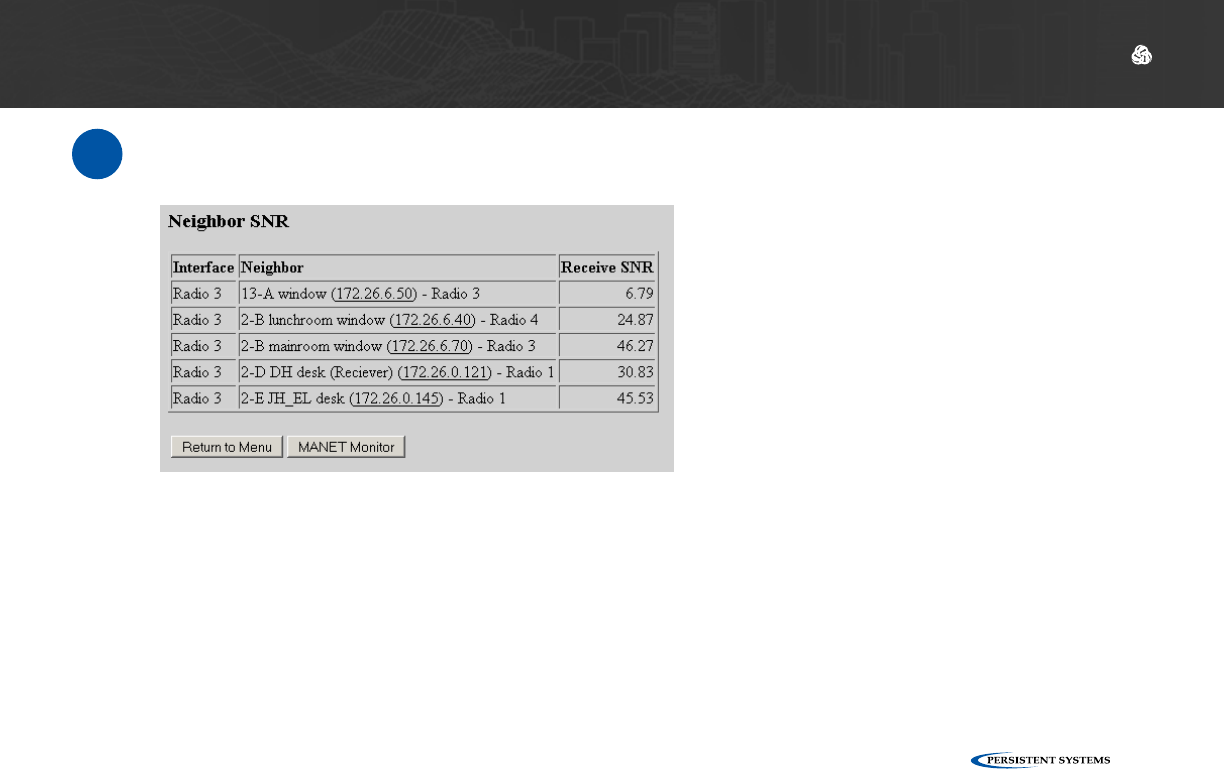
3Verify that all nodes are communicating with the network.
Notes:
▶This table only displays Neighbor Nodes (nodes directly connected without hops through other nodes. If you
spread nodes apart, they may disappear from the Neighbor Nodes Status page when they become connected via a
hop.
▶The Neighbor Nodes status page displays:
▶Node Names
▶IP Addresses
▶Receive Signal-to-Noise Ratio (SNR) between nodes

© 2010 - 2018 Persistent Systems, LLC – All Rights Reserved
72
TESTING CONNECTIVITY: THROUGHPUT TEST
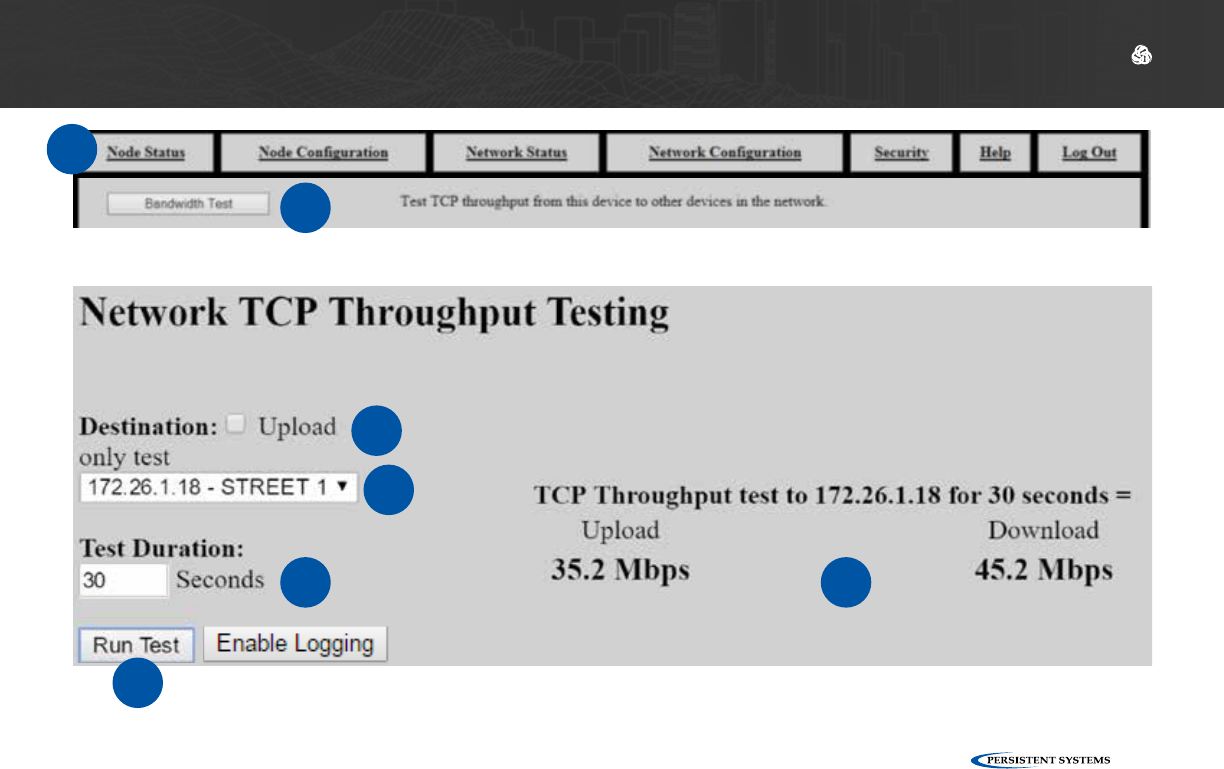
Perform a Throughput Test
1Click the Node Status tab.
2Click the Bandwidth Test button.
3Select a destination node for the through-
put test from the Destination drop-down
menu. This menu is populated from the
Node List.
4Enter the desired test duration (in sec-
onds) in the Test Duration field.
Note: Persistent Systems recommends the test
duration to be set to a minimum of 5 seconds.
5Check or uncheck the Upload only test
box. If this box is checked, only upload
speed to the destination node will be test-
ed.
6Click Run Test and wait for the test to com-
plete.
7The page will display the upload speed to
and download speed from the destination
node.
!WARNING!: During long duration tests,
data will continue to be sent for the full
specified duration even if a different data
flow is started or the web browser is exit-
ed.
© 2010 - 2018 Persistent Systems, LLC – All Rights Reserved 73
TESTING CONNECTIVITY: THROUGHPUT TEST
1
2
3
4
5
7
6
© 2010 - 2018 Persistent Systems, LLC – All Rights Reserved
74
TESTING CONNECTIVITY: THROUGHPUT TEST
Throughput Test Logging
1Click the Enable Logging button. 2When the throughput test is run, data will
be collected in a table at the bottom of the
page.

© 2010 - 2018 Persistent Systems, LLC – All Rights Reserved 75
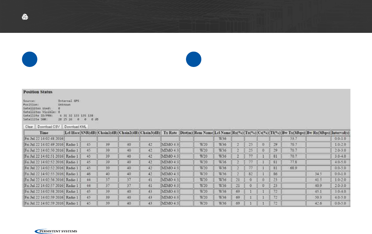
TESTING CONNECTIVITY: THROUGHPUT TEST
Position Status: displays GPS status information for the current node. See the Check GPS Status
section for an explanation of these fields.
Clear: clears all data from the table
Note: If Clear is not pressed before beginning a test, the new throughput test data will be append-
ed sequentially to the existing table of data.
Download CSV: downloads all throughput test data in the table as a CSV file
Download KML: downloads all throughput test data in the table as a KML file
Time: date and time for each line of test
data
Interface: interface used to communicate
during the test
SNR (dB): Signal-to-Noise Ratio at which
the destination node is heard
Chain 1/2/3 (dB): Signal-to-Noise Radio for
each chain on the source node
Tx Rate: MIMO or SISO rate used to
communicate between nodes in the format
MIMO|SISO [Rate]:[Number of streams].
Dist (m): distance between nodes, in
meters, if available
Rem Name: Node Name of the destination node
Lcl Name: Node Name of the source node
Rx(%): percentage of the channel used to receive
Tx(%): percentage of the channel used to
transmit
Cs(%): percentage of the channel occupied by
noise
Tl(%): total percentage of channel used
Bw Tx (Mbps): Upload Bandwidth, in Mbps
Bw Rx (Mbps): Download Bandwidth, in Mbps
Interval (s): time interval of the throughput test
for each line of throughput test data
© 2010 - 2018 Persistent Systems, LLC – All Rights Reserved
76
USING THE WEB MANAGEMENT INTERFACE: INDIVIDUAL NODE INFO
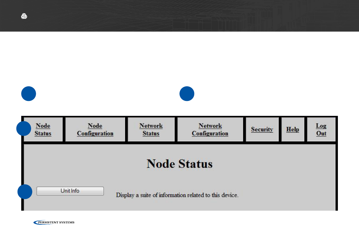
View Individual Node Information
Part IV: Using the Web Management Interface
1Click the Node Status tab. 2Click the Unit Info button.
1
2
© 2010 - 2018 Persistent Systems, LLC – All Rights Reserved 77
USING THE WEB MANAGEMENT INTERFACE: INDIVIDUAL NODE INFO
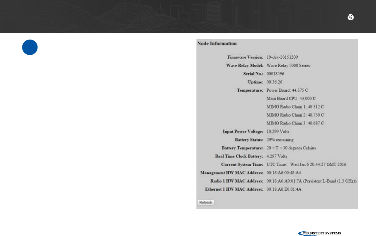
3The page will display:
Firmware Version: Wave Relay® firmware version
loaded on the node
Wave Relay Model: Device model
Serial No.: Serial number of the node
Uptime: Operating time since the node was last pow-
ered on or rebooted
Temperature: Temperature of the power board, main
board CPU, and all three RF chains
Input Power Voltage: Voltage supplied to node
Battery Status: Battery percentage remaining
Battery Temperature: Appx. temperature of battery
Real Time Clock Battery: Voltage of real-time-clock
keep-alive battery (on units with RTC)
Current System Time: Current system time of the
node (in both UTC and current time zone if not UTC)
Management HW MAC Address: MAC Address for
the management hardware of the node
Radio 1 HW MAC Address: MAC Address and fre-
quency band for the radio installed in the node
Ethernet 1 HW MAC Address: MAC Address for the
Ethernet port in the node
© 2010 - 2018 Persistent Systems, LLC – All Rights Reserved
78
USING THE WEB MANAGEMENT INTERFACE: INDIVIDUAL NODE INFO
Configuring Radio Settings for a Single Node
1Click the Node Con-
figuration tab. 2Click the Radio Con-
figuration button. 3Scroll to the Radio
Configuration section

© 2010 - 2018 Persistent Systems, LLC – All Rights Reserved 79
USING THE WEB MANAGEMENT INTERFACE: INDIVIDUAL NODE INFO
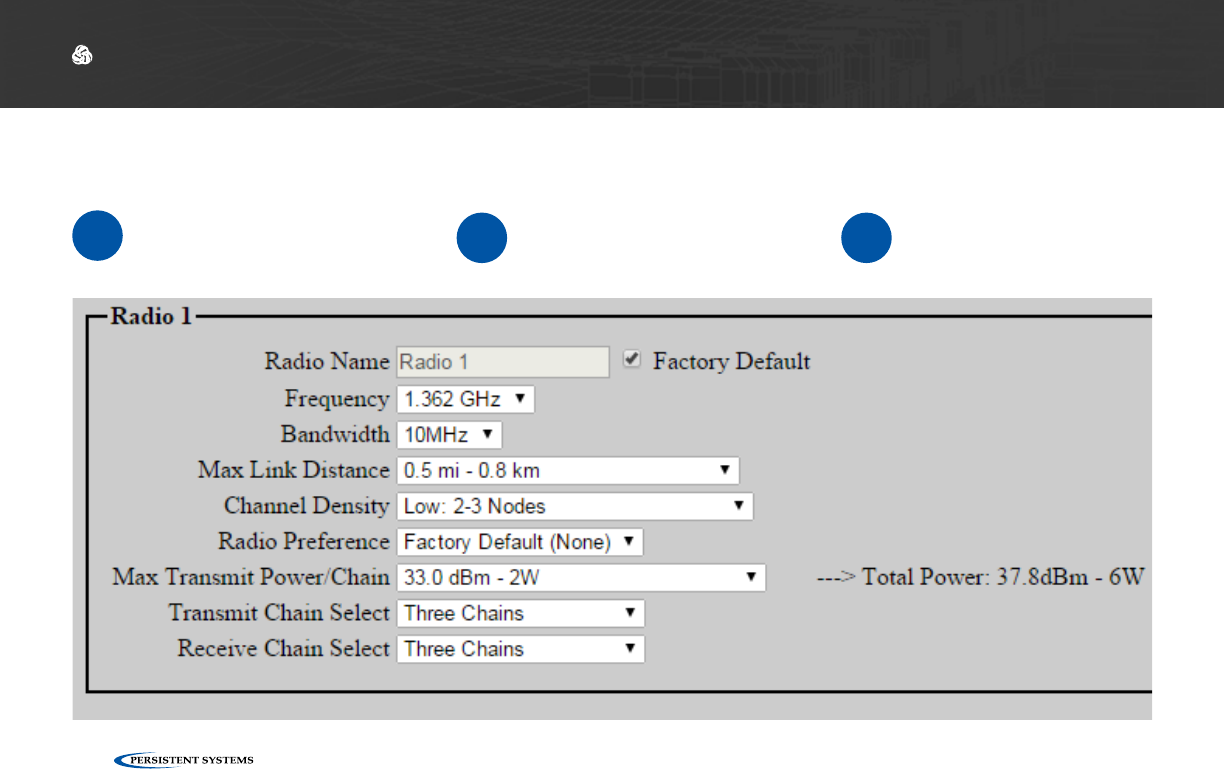
4
Configure settings if needed.
Note: changing these settings may cause poor performance or loss of connectivity.
Radio Name: Assign a name to the radio - check the Factory Default box to use the factory default name.
Frequency: Assign a frequency to operate on. Radios must be operating on the same frequency to communi-
cate. Ensure that the frequency is set to match the radio module installed in the unit.
Bandwidth: Assign a bandwidth to operate on. Nodes must be set to the same bandwidth to communi-
cate. Bandwidth should be increased for shorter distances and decreased for longer distances.
Max Link Distance: Set Max Link Distance to the maximum distance any individual link between nodes in
the network may need to be. All nodes on the network must be set to the same Max Link Distance.
Channel Density: Select the menu item that corresponds to the number of nodes in the network.
Radio Preference: Increasing radio preference will make the routing protocol more likely to choose this
radio when routing traffic in the network.
Max Transmit Power/Chain: Adjust transmit power of the radio - this setting is per chain. The total power
is shown to the right of the drop down menu.
Transmit Chain Select: Choose which RF chains to use to transmit - you may select one, two, or three
chains. The Auto setting will instruct the MPU5 to select Transmit Chains on its own.
Receive Chain Select: Choose which RF chains to use to receive - you may select one, two, or three chains.
The Auto setting will instruct the MPU5 to select Receive Chains on its own.
5Scroll to the bottom of the page and click Save & Reconfigure Unit.
!WARNING!: User MUST refer to the Professional Installer – Compliance Section of this manual
for approved power levels and approved channels. This warning applies only to RF-2100 with the
FCC ID 2AG3J-RF-2100 and RF-5100 with the FCC ID 2AG3J-RF-5100.
!WARNING!: User MUST refer to the Professional Installer – Compliance Section of this manual
for approved power levels and approved channels. This warning applies only to RF-2100 with the
FCC ID 2AG3J-RF-2100 and RF-5100 with the FCC ID 2AG3J-RF-5100.

© 2010 - 2018 Persistent Systems, LLC – All Rights Reserved
80
USING THE WEB MANAGEMENT INTERFACE: UPGRADING FIRMWARE
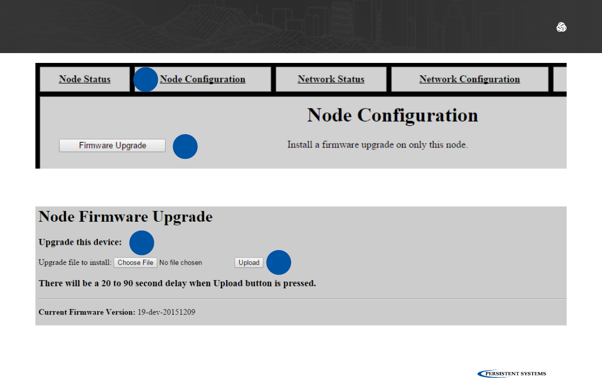
Upgrading Firmware
1Click the Node Configuration tab. 2Click the Firmware Upgrade button.
3Click Choose File, then navigate to and select the firmware file you wish to load.
4Click Upload.
WARNING!: A firmware upgrade will cause the node to be reconfigured, an operation that
causes a period of downtime. Do not perform a firmware upgrade during mission critical
operations that cannot tolerate such disruptions. Perform firmware upgrades only during
scheduled maintenance or other appropriate times.
!
!WARNING!: when upgrading or downgrading a node’s firmware, the LED will turn purple.
Do not unnecessarily disturb devices during an upgrade. Loss of power during the upgrade
can permanently damage the device.
Note: when new firmware is available for the MPU5, you will receive an email with the new firm-
ware file to upgrade your units.
Note: MPU5 firmware will NOT load on legacy Wave Relay® devices (MPU4, MPU3, QUAD).
© 2010 - 2018 Persistent Systems, LLC – All Rights Reserved 81
USING THE WEB MANAGEMENT INTERFACE: UPGRADING FIRMWARE
1
2
3
4

© 2010 - 2018 Persistent Systems, LLC – All Rights Reserved
82
USING THE WEB MANAGEMENT INTERFACE: CONFIGURATION FILES
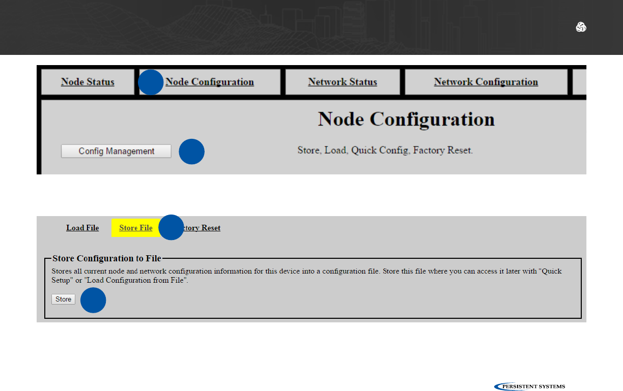
Creating a Configuration File
1Click the Node Configuration tab.
2Click the Config Management button.
3Click Store File.
4Click Store.
5A prompt will appear to choose where to save the configuration file.
Note: this file contains settings (both Network Configuration and Node Configuration settings) for the current
node only.
Note: do not save configuration files from nodes without a radio module installed.
© 2010 - 2018 Persistent Systems, LLC – All Rights Reserved 83
3
USING THE WEB MANAGEMENT INTERFACE: CONFIGURATION FILES
4
1
2

© 2010 - 2018 Persistent Systems, LLC – All Rights Reserved
84
USING THE WEB MANAGEMENT INTERFACE: CONFIGURATION FILES
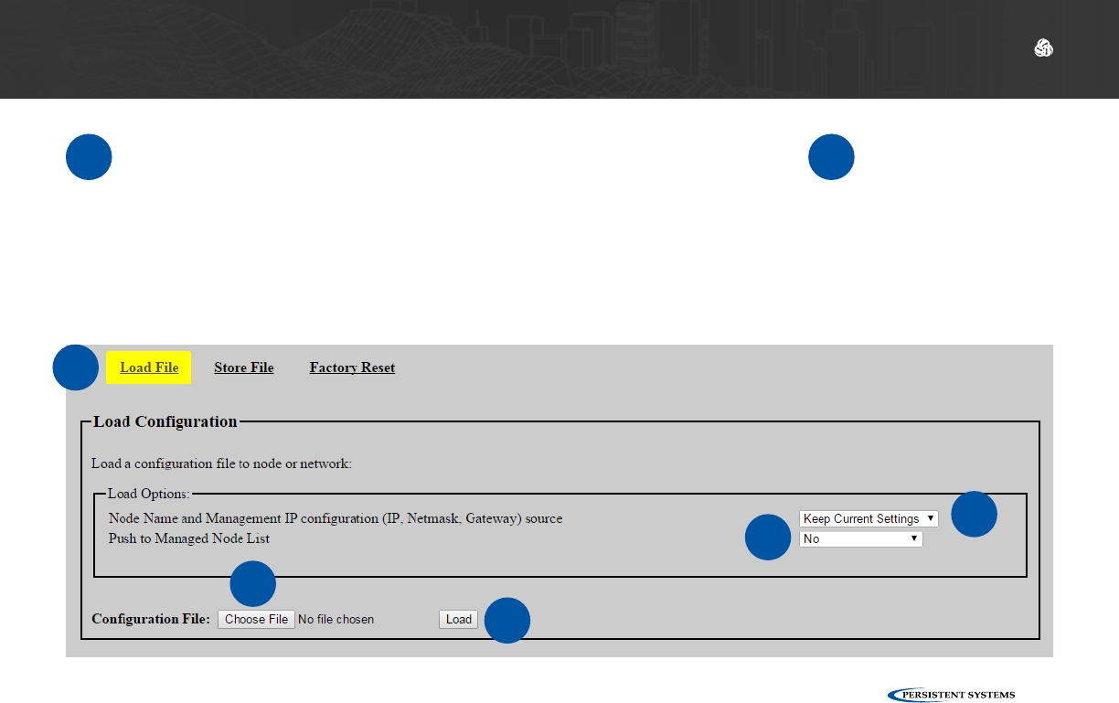
Loading Settings from a Configuration File
1Click the Node Configuration
tab. 2Click the Config Manage-
ment button. 3Click Load File.
4Configure Node Name and Management IP configuration (IP, Netmask, Gateway) source.
Keep Current Settings: Node Name, Management IP, Netmask, and Gateway will not
change after the configuration file is loaded.
Pull from Config File: Node Name, Management IP, Netmask, and Gateway will be set to
the values in the Config File you are loading.
Quick Setup: A box will appear that will allow you to enter a Node Name and Manage-
ment IP Address to be set when the Config File is loaded.
5Configure Push to Managed Node List.
No: The configuration file will be loaded on this node only.
Yes, Require All: The configuration file will be loaded on every node in the Managed
Node List if and only if all nodes in the Managed Node List are able to be contacted. If at
least one node in the Managed Node List is not able to be contacted, the configuration
file will not be loaded onto any nodes.
Yes, Any Available: The configuration file will be loaded onto any node in the Managed
Node List that is able to be contacted. The configuration file will not be loaded on any
nodes in the Node List that are not able to be contacted.
© 2010 - 2018 Persistent Systems, LLC – All Rights Reserved 85
USING THE WEB MANAGEMENT INTERFACE: CONFIGURATION FILES
6Click Choose File. Navigate to the desired configuration file to
load.
Note: the configuration file should be from a device with the same firmware
version and radio hardware configuration as the device being configured.
Note: do not load configuration files that have been saved from nodes with no
radio module installed.
7Click Load.
3
4
5
6
7
© 2010 - 2018 Persistent Systems, LLC – All Rights Reserved
86
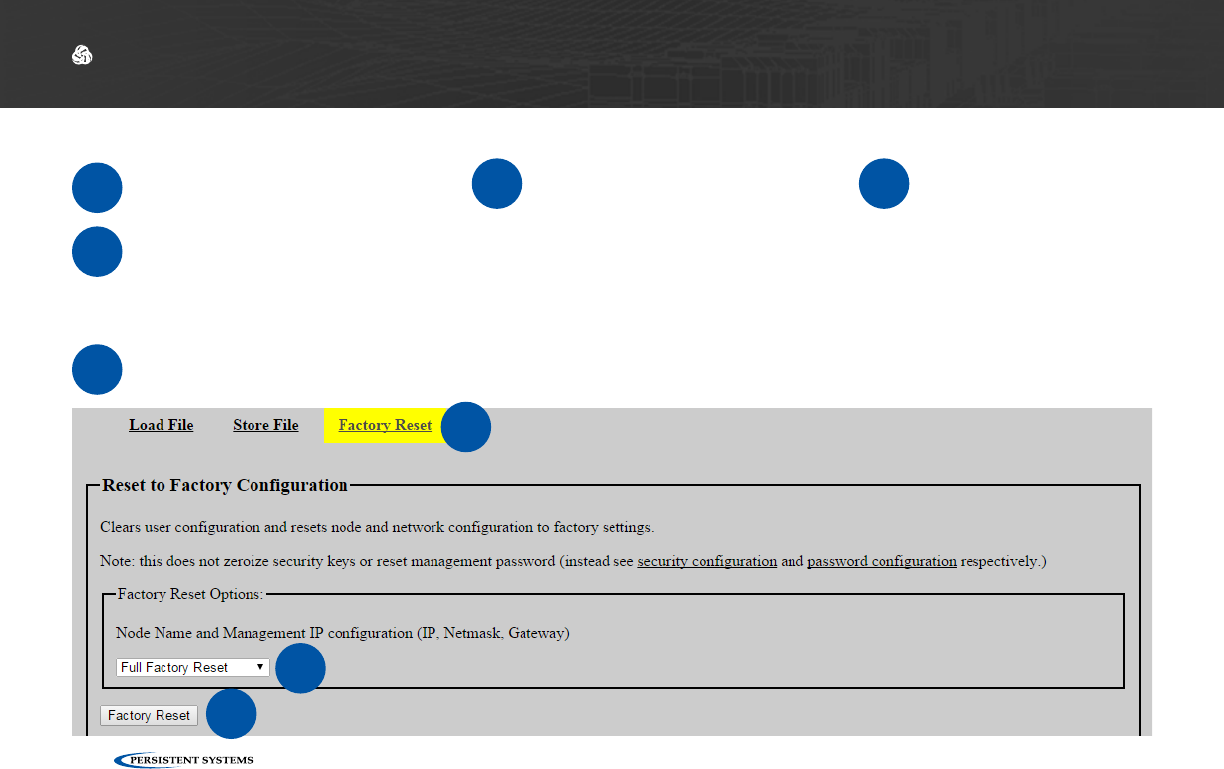
Reset Node to Factory Configuration
4Configure Node Name and Management IP configuration (IP, Netmask, Gateway).
Keep Current Settings: Node Name, Management IP, Netmask, and Gateway will not
change after the node is reset to factory configuration.
Full Factory Reset: All settings will be reset to factory configuration.
5When you are ready to remove all custom configuration and restore the node to factory set-
tings, click the Factory Reset button.
USING THE WEB MANAGEMENT INTERFACE: RESET TO FACTORY CONFIG
1Click the Node Configura-
tion tab. 2Click Config Management.3Click Factory Reset.
3
4
5
© 2010 - 2018 Persistent Systems, LLC – All Rights Reserved 87
USING THE WEB MANAGEMENT INTERFACE: CHECK GPS STATUS
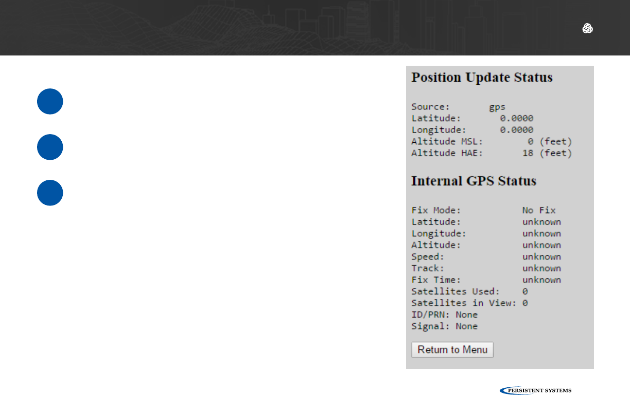
Check GPS Status
1Click the Node Status tab.
2Click the GPS Status button.
3The page will display:
Source: GPS information source
Latitude: Current latitude of the node
Longitude: Current longitude of the node
Altitude: Current altitude of the node as MSL
(above sea level) and HAE (above ellipsoid)

© 2010 - 2018 Persistent Systems, LLC – All Rights Reserved
88
USING THE WEB MANAGEMENT INTERFACE: NETWORK STATUS
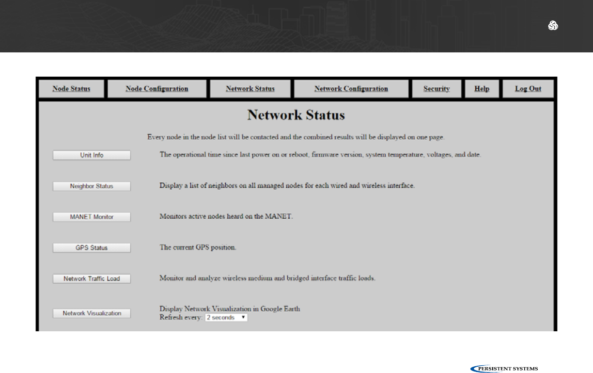
Network Status Tab
The Network Status tab allows you to view information about every node in the network at the
same time. Besides MANET Monitor, Network Visualization, and Channel Plan, each page displays
the same information as its counterpart on the Node Status page, but for every node in the net-
work.
Unit Info: general node information for every node in the network
Neighbor Status: neighbors and SNR for every node in the network
MANET Monitor: number of nodes in the network, serial number, node name, IP address, velocity
and direction, altitude, neighbors, battery percentage remaining, SNR for every node in the network
GPS Status: GPS information for every node in the network
Network Traffic Load: traffic load information for every node in the network
Network Visualization: view the network in Google Earth
Channel Plan: channel setting for each radio
IP Flow List: IP flows on the network
IP Multicast Status: IP Multicast information
© 2010 - 2018 Persistent Systems, LLC – All Rights Reserved 89
USING THE WEB MANAGEMENT INTERFACE: NETWORK STATUS

© 2010 - 2018 Persistent Systems, LLC – All Rights Reserved
90
USING THE WEB MANAGEMENT INTERFACE: NETWORK VISUALIZATION
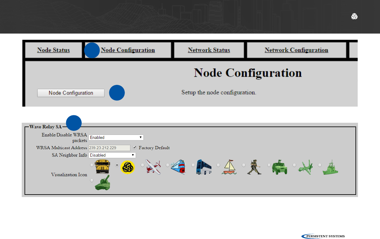
Configuring Visualization Settings
1Click the Node Configuration tab.
2Click Node Configuration.
3Scroll to the Wave Relay SA box.
4Configure Wave Relay Situational Awareness settings:
Enable/Disable WRSA Packets: select Enabled to enable Wave Relay SA
WRSA Multicast Address: defines the multicast address for sending and receiving Wave Re-
lay SA packets - uncheck the Factory Default box to modify this field.
SA Neighbor Info: enables or disabled SA Neighbor info - if disabled, Google Earth will not
display SNR lines, and SNR will not appear in the MANET monitor. Disable this setting to
reduce network overhead and improve scalability and performance of high density networks.
Visualization Icon: select an icon to represent the node in Google Earth.
© 2010 - 2018 Persistent Systems, LLC – All Rights Reserved 91
USING THE WEB MANAGEMENT INTERFACE: NETWORK VISUALIZATION
1
2
3

© 2010 - 2018 Persistent Systems, LLC – All Rights Reserved
92
USING THE WEB MANAGEMENT INTERFACE: NETWORK VISUALIZATION
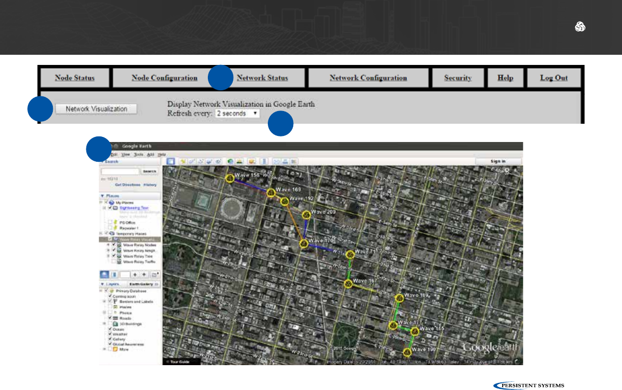
Viewing Network Visualization
1Click the Network Status tab.
2Scroll to Network Visualization.
3Select a refresh rate from the drop-down menu. Faster refresh rates will use more bandwidth.
4Click Network Visualization. A file named node-monitor.kml will download.
5Open this file in Google Earth to view network visualization.
© 2010 - 2018 Persistent Systems, LLC – All Rights Reserved 93
USING THE WEB MANAGEMENT INTERFACE: NETWORK VISUALIZATION
1
3
4
5

© 2010 - 2018 Persistent Systems, LLC – All Rights Reserved
94
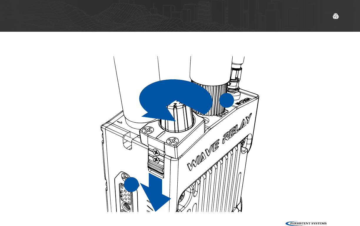
Zeroize the Security Key
1Pull down the zeroize latch on the top of the unit.
2With the zeroize latch held down, twist the Power Knob counterclockwise from the OFF
position to the Z position.
Note: the status indicator LED will blink red once when the key is zeroized.
Part V: Device Operation
DEVICE OPERATION: ZEROIZE THE SECURITY KEY
© 2010 - 2018 Persistent Systems, LLC – All Rights Reserved 95
DEVICE OPERATION: ZEROIZE THE SECURITY KEY
1
2
© 2010 - 2018 Persistent Systems, LLC – All Rights Reserved
96
DEVICE OPERATION: CONNECTING A CAMERA
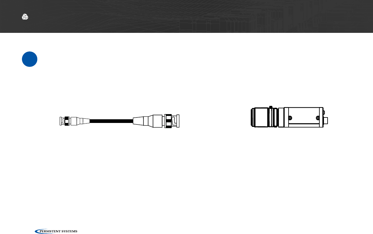
Connect a Camera to the MPU5
Parts List
≈
Camera with BNC output
HD-BNC to BNC Cable
CBL-VID-2001
For HD-SDI Connection:
© 2010 - 2018 Persistent Systems, LLC – All Rights Reserved 97
DEVICE OPERATION: CONNECTING A CAMERA
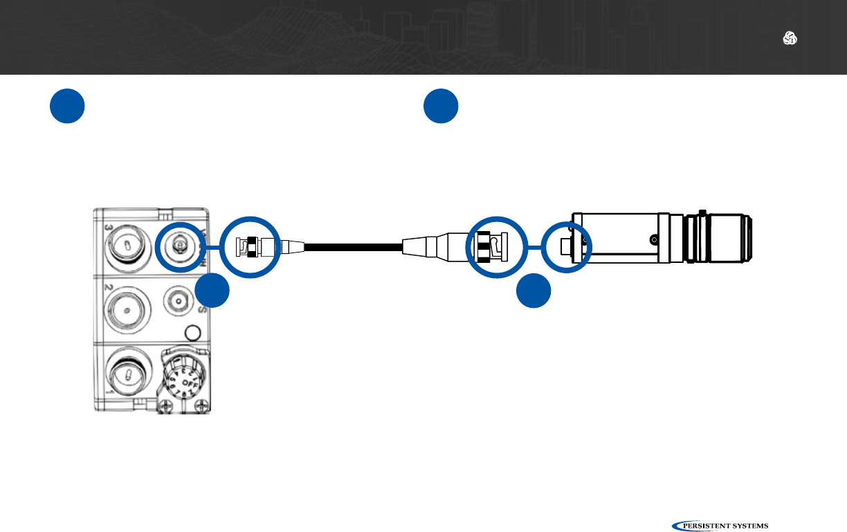
1Connect the HD-BNC end of CBL-
VID-2001 to the HD-BNC connector on
the top of the MPU5.
2Connect the BNC end of CBL-VID-2001 to
the BNC connector on the camera.
2
1
Note: the Video In connector does not supply power to the camera. Ensure that your camera is
properly powered via another source.
© 2010 - 2018 Persistent Systems, LLC – All Rights Reserved
98
DEVICE OPERATION: CONFIGURING VIDEO SETTINGS
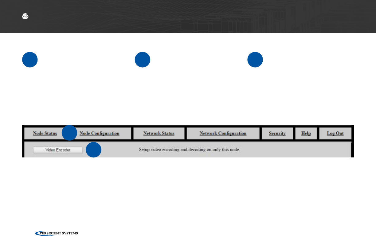
Configuring Video Settings
1Connect the MPU5 to the
Management Computer
and log into the Web Man-
agement Interface.
2Click the Node Configura-
tion tab. 3Click the Video Configu-
ration button.
2
3
© 2010 - 2018 Persistent Systems, LLC – All Rights Reserved 99
DEVICE OPERATION: CONFIGURING VIDEO SETTINGS
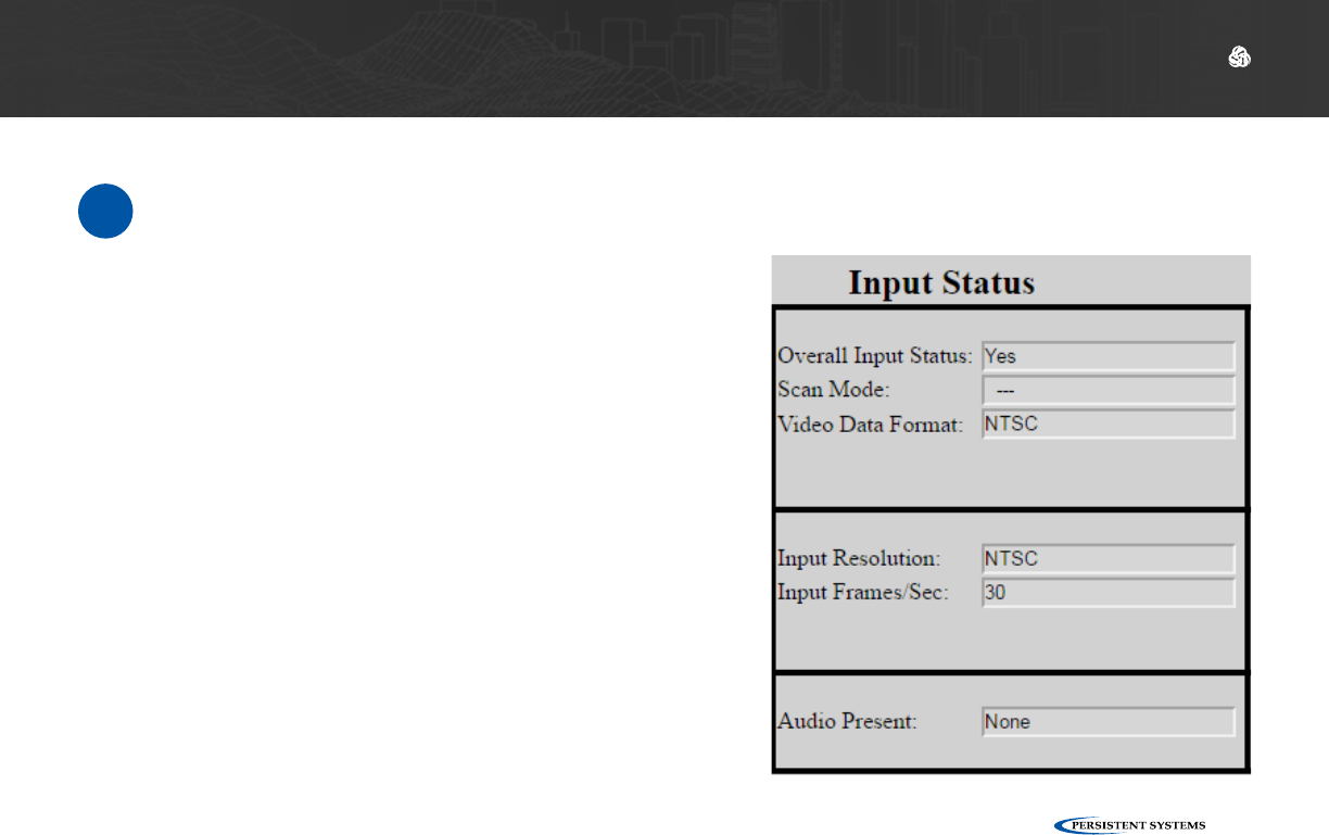
Check Camera Input Status
Overall Input Status: displays Yes if a camera is connect-
ed; displays No otherwise.
Scan Mode: scan mode setting of the connected camera,
if available
Video Data Format: output format setting of the con-
nected camera, if available
Input Resolution: resolution setting of the connected
camera, if available
Input Frames/Sec: frame rate setting of the connected
camera, if available
Audio Present: audio status from the connected camera,
if available
1The left column displays status information for the camera connected to the MPU5. Use this
status information to verify that the connected camera is configured and working properly.
© 2010 - 2018 Persistent Systems, LLC – All Rights Reserved
100
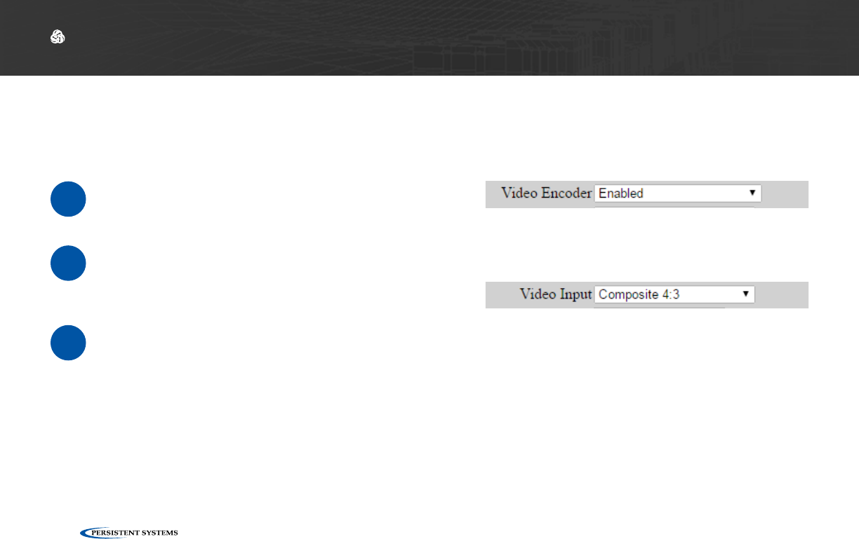
Encoder Configuration
Enable/Disable Video Encoding
DEVICE OPERATION: CONFIGURING VIDEO SETTINGS
The center column displays configuration settings for the MPU5’s onboard video encoder.
1In the Enable/Disable drop-down menu,
select Enabled.
2To disable Video, select Disabled.
Select Video Input
1Select the video source that corresponds to your camera from the Video Input drop-down
menu.
3G-SDI: 3G-SDI input via the Video In connector on the top of the MPU5
Composite 4:3: Composite input with a 4:3 aspect ratio via the Video In connector on
the top of the MPU5
Composite 16:9: Composite input with a 16:9 aspect ratio via the Video In connector on
the top of the MPU5
Note: you MUST manually configure the correct input source. If the correct input source is not
selected, input status will show no camera detected.
© 2010 - 2018 Persistent Systems, LLC – All Rights Reserved 101
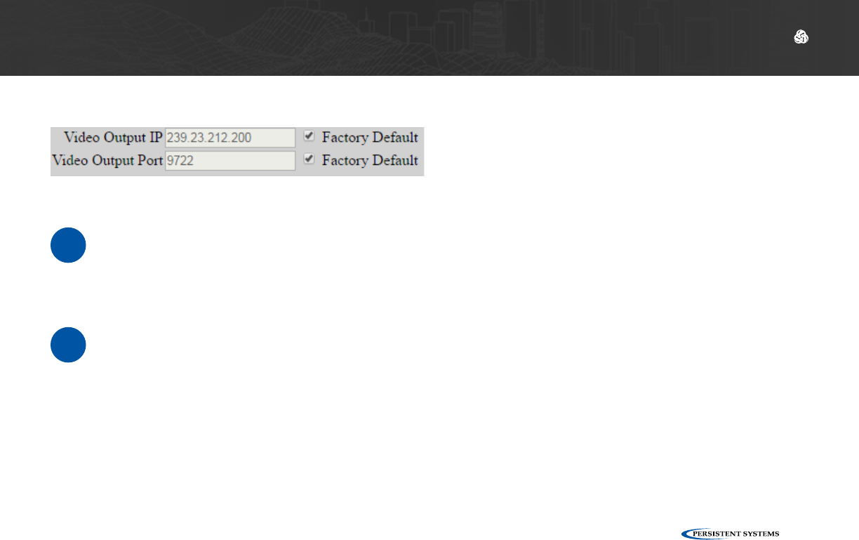
Configure Video Output IP Address and Port
DEVICE OPERATION: CONFIGURING VIDEO SETTINGS
1Enter an IP address for the video in the Video Output IP field. Pick a unique IP address.
Uncheck the Factory Default box to make changes to this field. Check the Factory Default
box to use the Factory Default Video Output IP.
2Enter a port for the video stream in the Video Output Port field. Uncheck the Factory De-
fault box to make changes to this field. Check the Factory Default box to use the Factory
Default Video Output Port.
© 2010 - 2018 Persistent Systems, LLC – All Rights Reserved
102
DEVICE OPERATION: CONFIGURING VIDEO SETTINGS
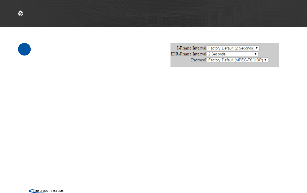
Advanced Video Configuration Options
1Click Show/Hide Advanced Settings. This
will show or hide drop-down menus for
I-Frame Interval, IDR-Frame Interval, and
Protocol.
I-Frame Interval (Advanced): Sets the time between I-Frames (in seconds). The shorter amount
of time between I-Frames, the better video quality will be, but the video stream will use more
bandwidth. It is not recommended for non-advanced users to change this setting.
IDR-Frame Interval (Advanced): Sets the time between IDR-Frames (in seconds). Increasing IDR-
Frame interval will decrease the bandwidth used by the stream, but it may reduce video quality. It is
not recommended for non-advanced users to change this setting.
Note: Available IDR-Frame Interval options change based on the selected I-Frame interval. If you
change I-Frame Interval and the selected IDR-Frame Interval setting is available for that I-Frame
Interval, the IDR-Frame Interval will not change. If you change I-Frame Interval and the selected IDR-
Frame Interval setting is not available for that I-Frame Interval, IDR-Frame Interval will be set to the
factory default setting for that I-Frame Interval.
Protocol (Advanced): Selects the streaming protocol for the video stream. Options are: MPEG-TS/
UDP or RTP/UDP.
© 2010 - 2018 Persistent Systems, LLC – All Rights Reserved 103
DEVICE OPERATION: CONFIGURING VIDEO SETTINGS
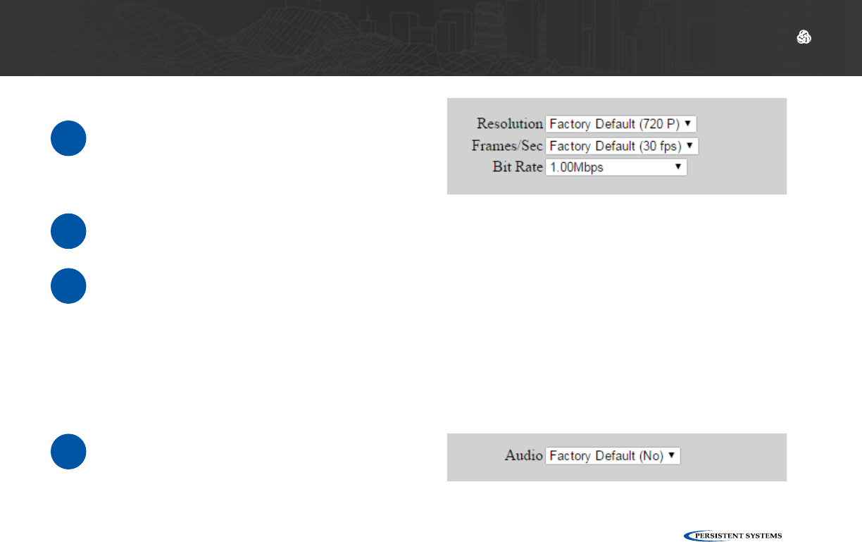
Select Video Encoding Settings
1Select a resolution from the Resolution
drop-down menu. This setting selects
the resolution at which video will be
encoded. Options are:
4If you wish to encode audio with the
video stream, select Yes from the Audio
drop-down menu. Otherwise, select
No.
2Select a frame rate from the Frame Rate drop-down menu. This setting selects the frame rate
at which video will be encoded.
3Select a bit rate from the Bit Rate drop-down menu. This setting selects the bit rate at which
video will be encoded.
Note: Available frame rate and bit rate options change based on the selected resolution. If
you change resolution and the selected frame rate and bit rate settings are available for that
resolution, they will not change. If you change resolution and the selected frame rate or bit
rates settings are not available for that resolution, frame rate and bit rate will be set to the
factory default setting for that resolution.
© 2010 - 2018 Persistent Systems, LLC – All Rights Reserved
104
DEVICE OPERATION: CONFIGURING VIDEO SETTINGS
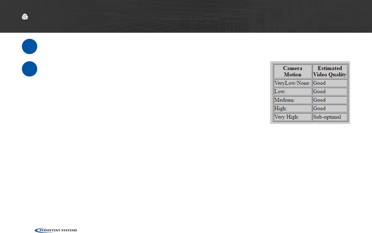
6When you are finished configuring settings, click Save & Reconfigure Unit.
7Use the Camera Motion & Estimated Video Quality table on the
bottom left of the page to check if the bit rate you have selected
will be sufficient for good-quality video based on how much your
camera will be moving. If it is not, adjust the bit rate setting ac-
cordingly.
© 2010 - 2018 Persistent Systems, LLC – All Rights Reserved 105
DEVICE OPERATION: CONFIGURING VIDEO SETTINGS
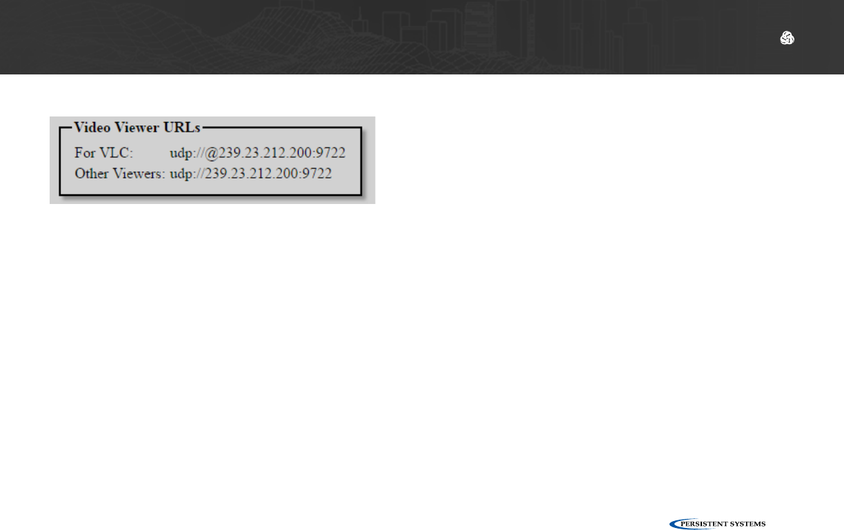
Video Viewer URLs
The Video View URLs page will display two URLs below the Video Configuration settings. To pull
video from this node, enter the For VLC URL into VLC or the Other Viewers URL in another video
player.
Note: if you change Video Output IP or Video Output Port on the Video Configuration page,
these URLs will change as well.
© 2010 - 2018 Persistent Systems, LLC – All Rights Reserved
106
DEVICE OPERATION: CONFIGURING VIDEO SETTINGS
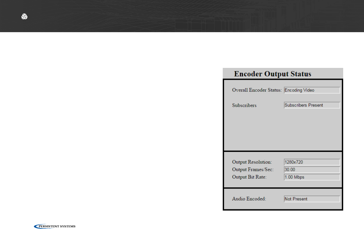
Video Encoding Status
The center column displays configuration settings for the MPU5’s onboard video encoder.
Overall Encoder Status: displays whether this node is
encoding video or not.
Subscribers: displays whether there are users on the
network subscribing to the video from this node.
Note: if no one is subscribed to the video from this node,
the node will not encode video.
Output Resolution: displays the resolution of the encoded
video being output
Output Frames/Sec: displays frame rate of the encoded
video being output
Output Bit Rate: displays the bit rate of the encoded
video being output
Audio Encoded: displays whether audio is being encoded
with the video stream or not

© 2010 - 2018 Persistent Systems, LLC – All Rights Reserved 107
DEVICE OPERATION: CONFIGURING VIDEO SETTINGS
What do I do if video is not being encoded?
?
Ensure that the camera is powered and all cables are connected securely to the correct connectors.
1
If there are no subscribers to the video, video will not be encoded. Check if video is being encoded when
a subscriber is present.
4
Ensure Video Encoding is enabled on the node. You must click the Save & Reconfigure Unit button for
settings to take effect.
2
Ensure the correct Video Viewer URL is entered into your video viewer.
5
Ensure that the correct video input is selected on the Video Encoding Configuration page.
3
© 2010 - 2018 Persistent Systems, LLC – All Rights Reserved
108
DEVICE OPERATION: CONFIGURING VIDEO KIOSK MODE
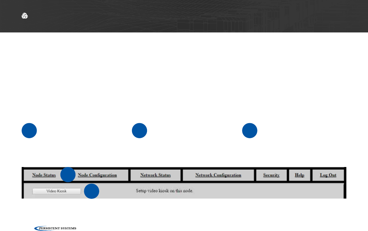
Configuring Video Kiosk Mode
1Connect the MPU5 to the
Management Computer
and log into the Web Man-
agement Interface.
2Click the Node Configura-
tion tab. 3Click the Video Configu-
ration button.
2
3
Video Kiosk Mode allows you set up the MPU5 as a kiosk video player. When Kiosk Mode is en-
abled, up to four video feeds may be configured. The MPU5 will automatically display one of these
video feeds, and the standard MPU5 Android interface is disabled. The video being viewed can be
changed from within the Web Management Interface or toggled by using the keypad.
Video Kiosk Mode
© 2010 - 2018 Persistent Systems, LLC – All Rights Reserved 109
DEVICE OPERATION: CONFIGURING VIDEO KIOSK MODE
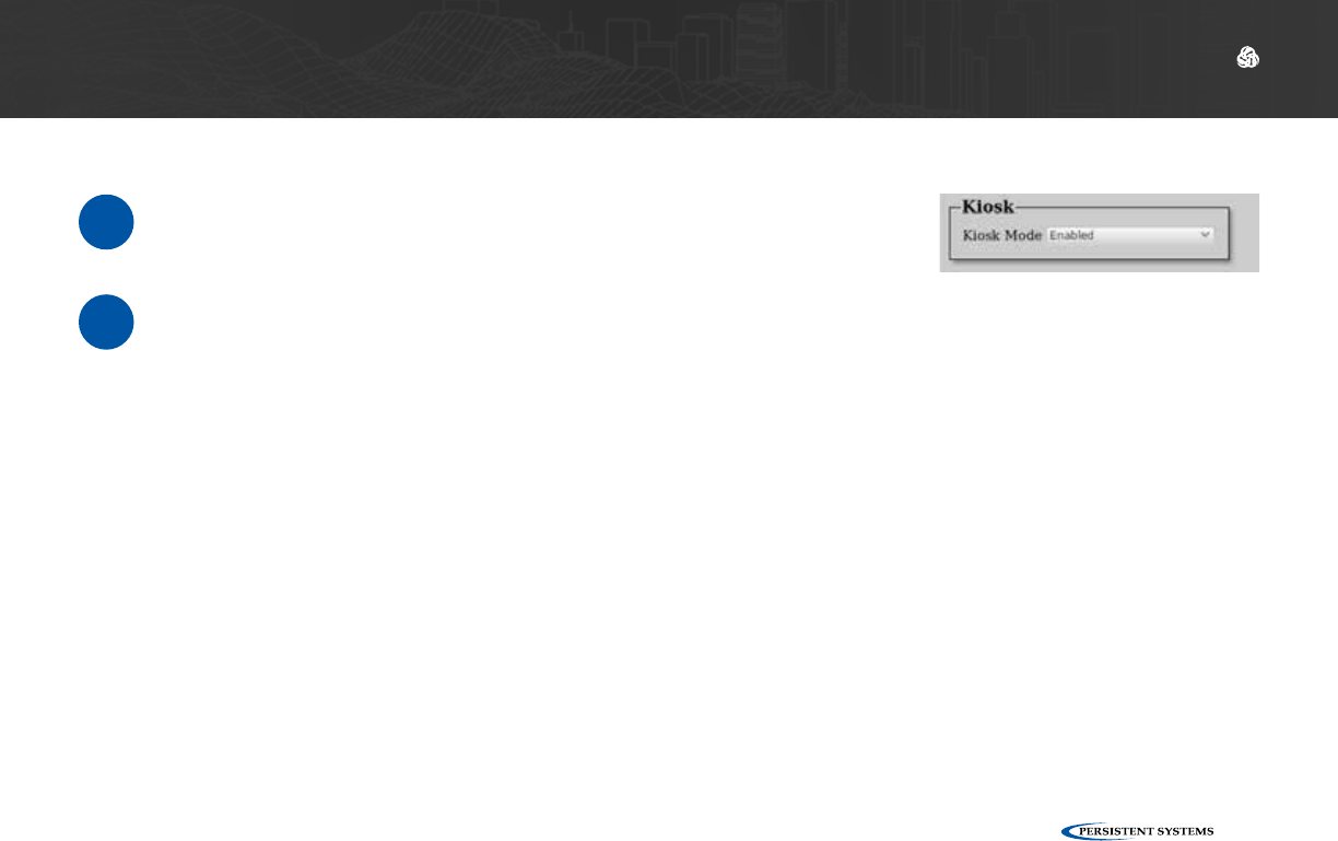
Enable Video Kiosk Mode
1In the Enable/Disable drop-down menu, select Enabled.
2To disable Video, select Disabled.
© 2010 - 2018 Persistent Systems, LLC – All Rights Reserved
110
DEVICE OPERATION: CONFIGURING VIDEO KIOSK MODE
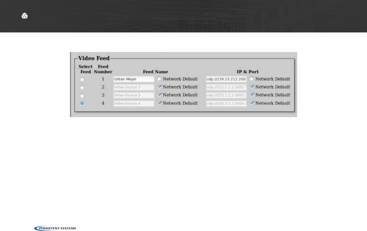
Configure Video Feed Settings
The Video Feed box configures settings for each of the 4 feeds to be viewed in Video Kiosk Mode.
Select Feed: this column controls which video feed will be displayed by default in Video Kiosk
Mode. Click the circle for the video feed you wish to be the default.
Feed Number: displays the number of each of the four video feeds. When in Video Kiosk Mode,
you may select a feed to be displayed using the corresponding keypad number or the left and right
arrow keys.
Feed Name: assigns a custom name to each video feed. Uncheck the Network Default box to edit
this field.
IP & Port: sets the IP address and Port for the video feed to be accessed in the format <IP Ad-
dress>:<Port>. Uncheck the Network Default box to edit this field.
© 2010 - 2018 Persistent Systems, LLC – All Rights Reserved 111
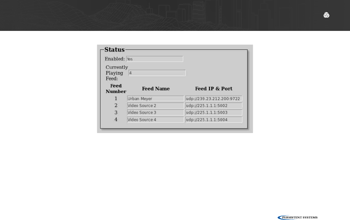
Video Kiosk Mode Status
The Status box displays Video Kiosk Mode status information.
Enabled: displays Yes if Video Kiosk Mode is enabled and displays No if Video Kiosk Mode is dis-
abled
Currently Playing Feed: displays the number of the video feed that is currently being viewed in
Video Kiosk Mode
Feed Number: displays the number of each of the four video feeds
Feed Name: displays the name for each video feed
Feed IP & Port: displays the IP address and port for each video feed
DEVICE OPERATION: CONFIGURING VIDEO KIOSK MODE

© 2010 - 2018 Persistent Systems, LLC – All Rights Reserved
112
DEVICE OPERATION: VIDEO KIOSK MODE OPERATION
Video Kiosk Mode Disabled Video Kiosk Mode Enabled
Video Kiosk Mode Operation
▶The video kiosk app will automatically restart if video encoding settings change or a problem
occurs.
▶The only way to exit the video kiosk player is to disable Video Kiosk Mode from the Web Man-
agement Interface.
© 2010 - 2018 Persistent Systems, LLC – All Rights Reserved 113
DEVICE OPERATION: VIDEO KIOSK MODE OPERATION
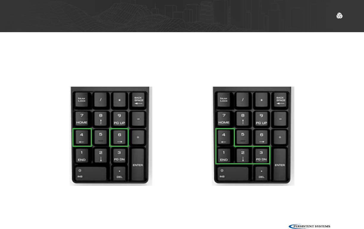
▶The video feed being viewed can be changed from the Web Management Interface or from the
app:
▶With num lock disabled, use the left and right arrow keys
▶With num lock enabled, use the keypad to select the corresponding video feed
Num Lock Disabled Num Lock Enabled
© 2010 - 2018 Persistent Systems, LLC – All Rights Reserved
114
DEVICE OPERATION: CONNECTING AN EUD OR HANDHELD DISPLAY
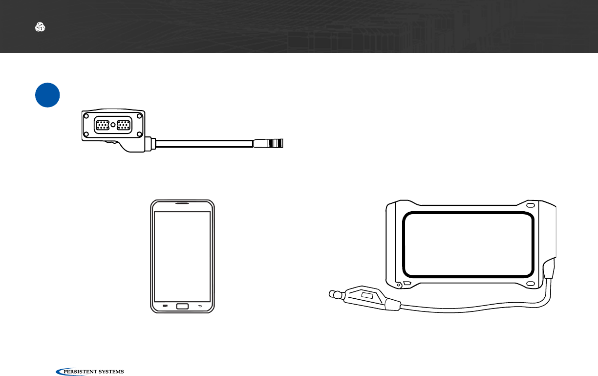
Connect an EUD or Handheld Display to the MPU5
Parts List
≈
EUD IP67 Enclosure
MOLLE-IP67-N3
22-Pin to 6-Pin USB Push Pull Android™ Tether Cable
CBL-DATA-2004
Android™ EUD
ACC-EUD-0001
© 2010 - 2018 Persistent Systems, LLC – All Rights Reserved 115
DEVICE OPERATION: CONNECTING AN EUD OR HANDHELD DISPLAY
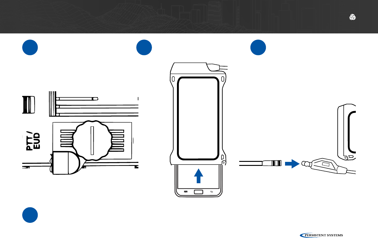
1Connect CBL-DATA-2004
to the PTT/EUD side con-
nector on the MPU5.
2Insert the Android™ EUD
into the Juggernaut Case. 3
4
Connect the 6-Pin Push
Pull connector on the
Juggernaut Case to the
6-Pin Push Pull connec-
tor on CBL-DATA-2004.
The MPU5 Android™ OS will be displayed on the EUD or Display.
© 2010 - 2018 Persistent Systems, LLC – All Rights Reserved
116
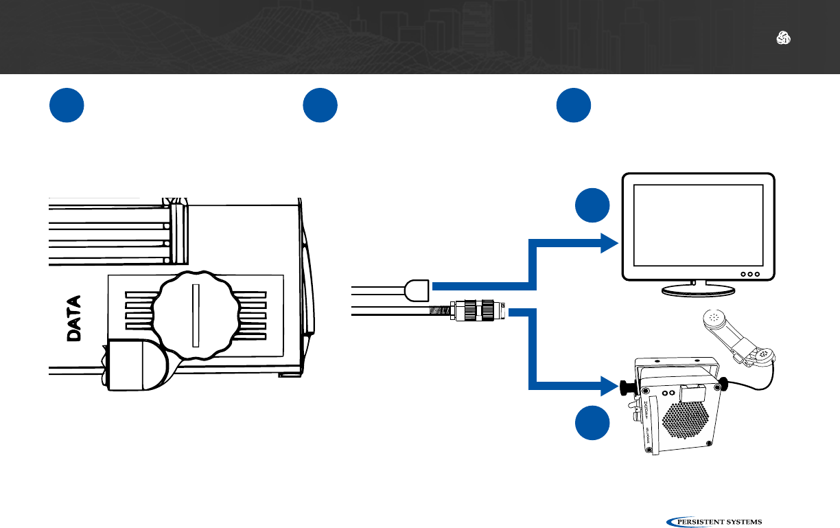
DEVICE OPERATION: CONNECTING A MONITOR OR TV
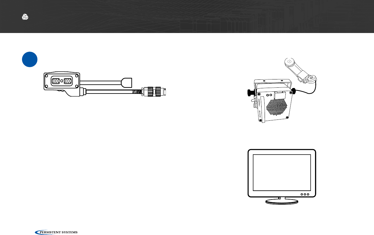
Connect a Monitor or TV to the MPU5
Parts List
≈
Monitor or TV with HDMI Input
Speaker Box or Headset with U-328 Connector
22-Pin to Audio and Video Out
CBL-DATA-3002
© 2010 - 2018 Persistent Systems, LLC – All Rights Reserved 117
DEVICE OPERATION: CONNECTING A MONITOR OR TV
1Connect CBL-DATA-3002
to the DATA side connec-
tor on the MPU5.
2Connect the speaker box
or headset to the U-328
audio connector on
CBL-DATA-3002.
3Connect the HDMI end
of CBL-DATA-3002 to
the HDMI Input on the
monitor or TV.
2
3

© 2010 - 2018 Persistent Systems, LLC – All Rights Reserved
118
DEVICE OPERATION: CONNECTING A MONITOR OR TV
Why can’t I see video on my Monitor or TV?
?
Ensure that the Monitor or TV is powered on.
1
Ensure that all cables are connected properly.
2
Ensure that the Monitor or TV is set to the correct
HDMI input.
3
Reboot the node.
4
© 2010 - 2018 Persistent Systems, LLC – All Rights Reserved 119
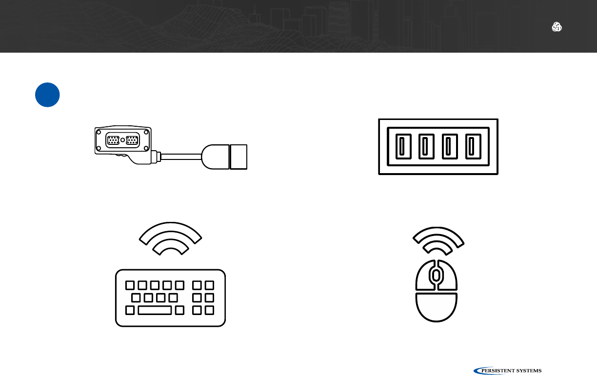
DEVICE OPERATION: CONNECTING USB ACCESSORIES
Connect USB Accessories to the MPU5
Parts List
≈
USB Hub
(Optional)
USB Keyboard
(Optional)
USB Mouse
(Optional)
22-Pin to Type A Female USB 2.0 Receptacle
CBL-DATA-2003
© 2010 - 2018 Persistent Systems, LLC – All Rights Reserved
120
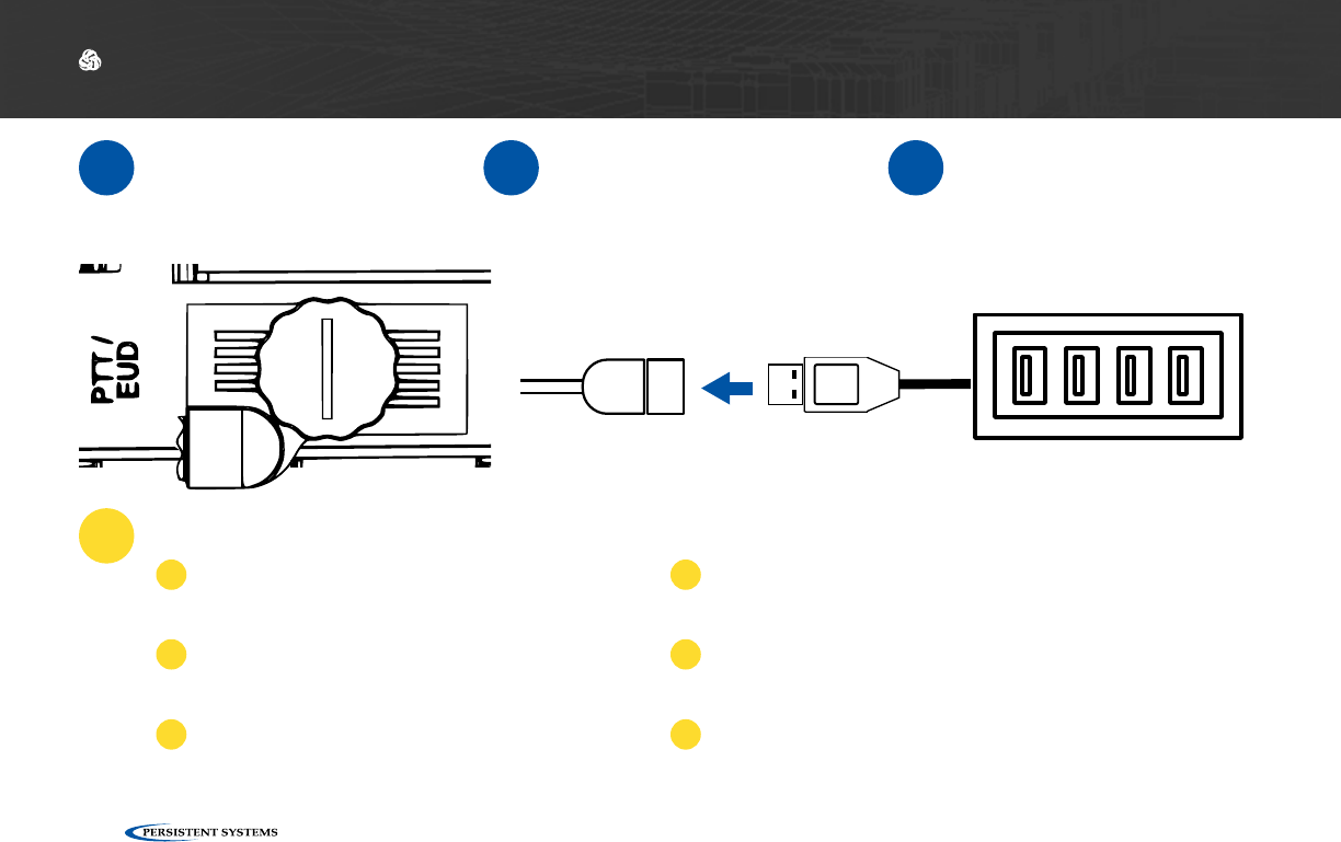
DEVICE OPERATION: USB ACCESSORIES
1Connect CBL-DATA-2003
to an unused side connec-
tor on the MPU5.
2Connect the USB Hub or
one USB accessory to the
USB receptacle on the
end of CBL-DATA-2003.
3If you are using a USB
Hub, connect USB acces-
sories to the USB recep-
tacles in the USB Hub.
Why don’t my USB accessories work?
?Ensure all cables are connected properly.
1
Ensure that all wireless accessories (key-
boards/mice/etc.) are powered (i.e. batteries
are not dead)
2
If you are using a USB Hub, connect the USB
accessory directly to CBL-DATA-2003. If the
accessory works, replace the USB hub.
3
If available, test a different CBL-DATA-2003. If the
accessory works, the original CBL-DATA-2003 may be
defective.
4
Your USB accessory may not be compatible. Contact
Persistent Systems support.
4
Reboot the node.
5
© 2010 - 2018 Persistent Systems, LLC – All Rights Reserved 121
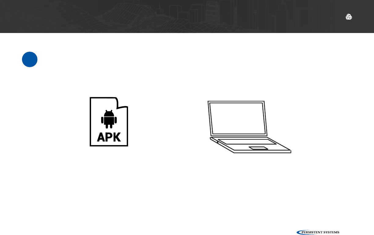
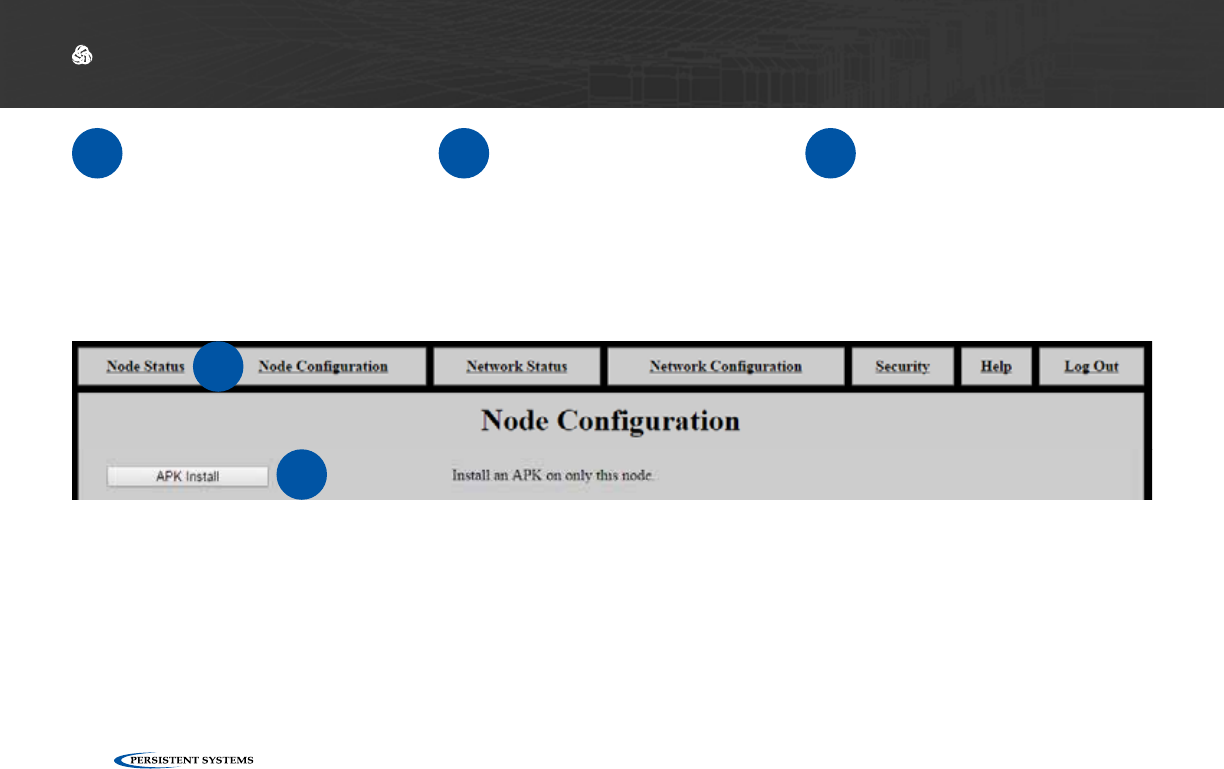
DEVICE OPERATION: INSTALLING APPS
Install Android™ Apps on the MPU5
Parts List
≈
.apk file for Android™ App(s) Management Computer
Note: the Operating System on the MPU5 is Android™ version 5.0 (Lollipop). Ensure that the app
you wish to install is compatible with this version of the Android™ OS.
© 2010 - 2018 Persistent Systems, LLC – All Rights Reserved
122
DEVICE OPERATION: INSTALLING APPS
1Connect the MPU5 to the
Management Computer
and log into the Web Man-
agement Interface.
2Click the Node Configura-
tion tab. 3Click APK Install.
2
3
© 2010 - 2018 Persistent Systems, LLC – All Rights Reserved 123
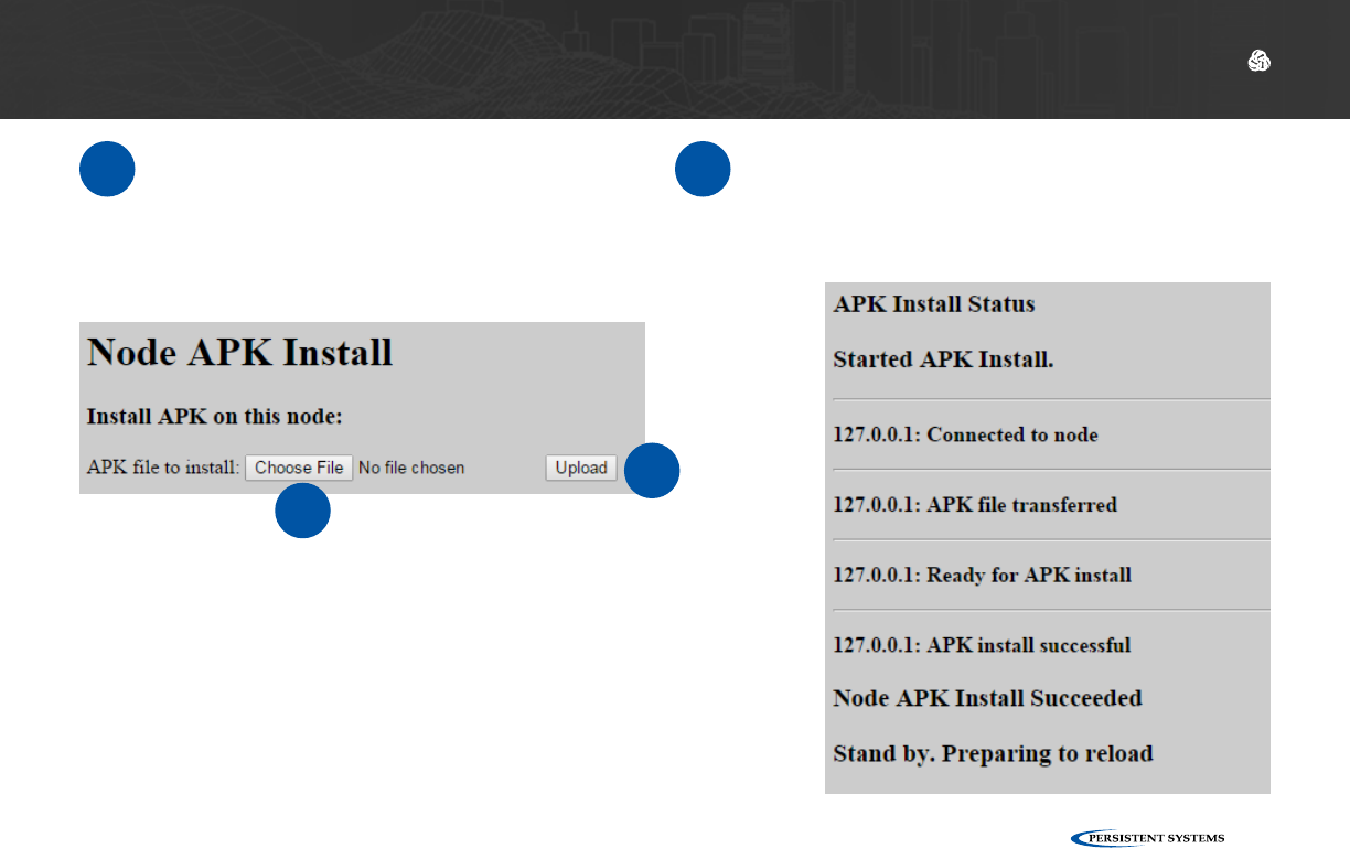
DEVICE OPERATION: INSTALLING APPS
4Click Choose File and navigate to the
.apk file you wish to install. 5Click Upload and wait for the on-screen
prompt to say Node APK Install Succeed-
ed. The page will then reload.
45
© 2010 - 2018 Persistent Systems, LLC – All Rights Reserved
124
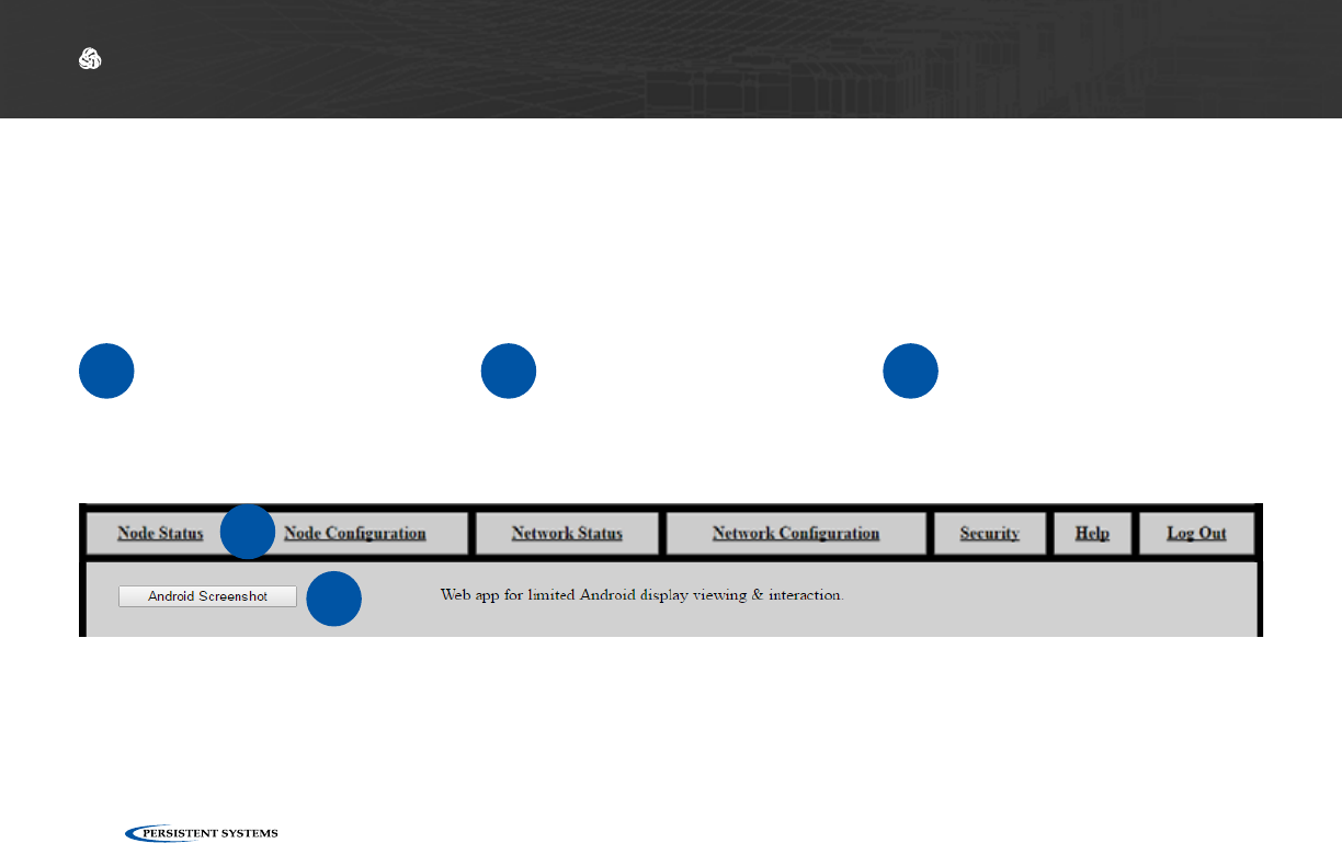
View Android™ OS via the Web Management Interface
DEVICE OPERATION: ANDROID™ SCREENSHOT
▶The Android™ Screenshot page allows users to view and control Android™ on the MPU5 via the
Web Management Interface
Accessing the Android™ Screenshot Page
1Connect the MPU5 to the
Management Computer
and log into the Web Man-
agement Interface.
2Click the Node Status tab. 3Click the Android™
Screenshot button.
2
3

© 2010 - 2018 Persistent Systems, LLC – All Rights Reserved 125
DEVICE OPERATION: ANDROID™ SCREENSHOT
Using the Android™ Screenshot Page
Mouse Click: tap/swipe as if using a touch screen EUD
Reload Screenshot: refreshes the displayed image of the Android™ OS
Power: powers on/off the Android™ display - this will not close apps
Back: returns to the previous page
Home: returns to the Android™ Home Screen
App Switch: allows the user to toggle between open apps

© 2010 - 2018 Persistent Systems, LLC – All Rights Reserved
126
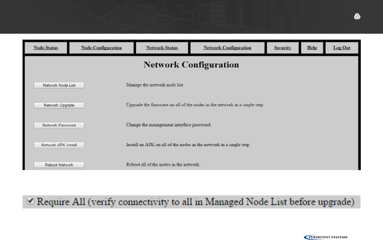
DEVICE OPERATION: NETWORK CONFIGURATION
Network Configuration Tab
The Network Configuration tab allows you to perform actions on all nodes in the network.
Network Node List: manage the Network Node List
Network Upgrade: upgrade firmware on all nodes
Network Password: change the Management Password for all nodes
Network APK Install: install an APK on all nodes in the network
Reboot Network: reboot all nodes in the network
Each action on this tab is the same as the corresponding action on the Node Configuration tab.
Network Upgrade and Network APK install have a box labeled Require All. If this box is checked,
the firmware or .apk file will only be installed if and only if all nodes in the Network Node List are
able to be contacted. If any node is unable to be contacted, the firmware or .apk file will not be
installed on any node. If this box is unchecked, the firmware or .apk file will only be installed on
nodes that are able to be contacted. The firmware or .apk file will not be installed on nodes that
are unable to be contacted.
© 2010 - 2018 Persistent Systems, LLC – All Rights Reserved 127
DEVICE OPERATION: NETWORK CONFIGURATION
© 2010 - 2018 Persistent Systems, LLC – All Rights Reserved
128
DEVICE OPERATION: CONNECTING A PTT DEVICE
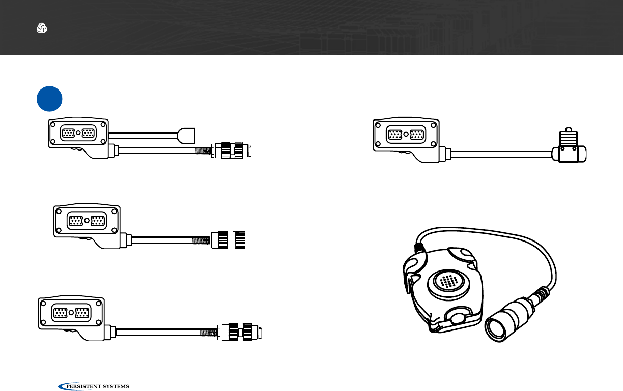
Connect a PTT Device to the MPU5
Parts List
≈
22-Pin to audio and Video Out
CBL-DATA-3002
22-Pin to U-329
CBL-AUD-0001
22-Pin to U-328
CBL-AUD-0002
22-Pin to U94 Receptacle
CBL-AUD-0003
The cable you need is dependent on what connec-
tor your PTT device has.
Compatible Push-to-Talk device
© 2010 - 2018 Persistent Systems, LLC – All Rights Reserved 129
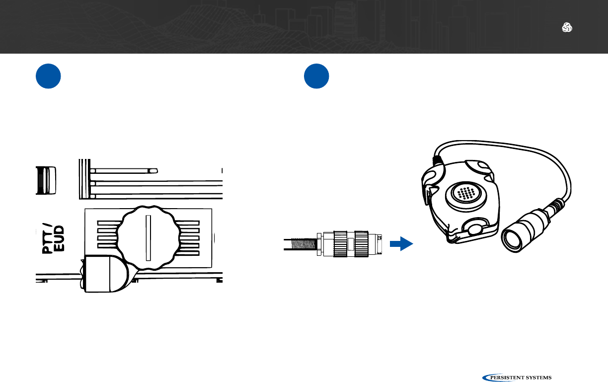
DEVICE OPERATION: CONNECTING A PTT DEVICE
1Connect the cable to the PTT/EUD side
connector on the MPU5. 2Connect the PTT device to the connector
on the end of the cable.
© 2010 - 2018 Persistent Systems, LLC – All Rights Reserved
130
DEVICE OPERATION: CONFIGURING PTT SETTINGS
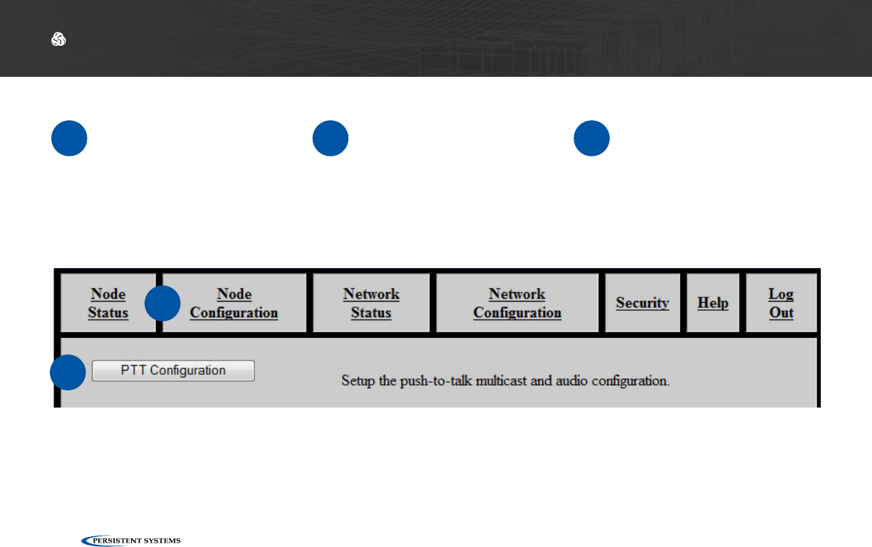
Configure PTT Settings
1Connect the MPU5 to the
Management Computer
and log into the Web Man-
agement Interface.
2Click the Node Configura-
tion tab. 3Click the PTT Configura-
tion button.
2
3
© 2010 - 2018 Persistent Systems, LLC – All Rights Reserved 131
DEVICE OPERATION: CONFIGURING PTT SETTINGS
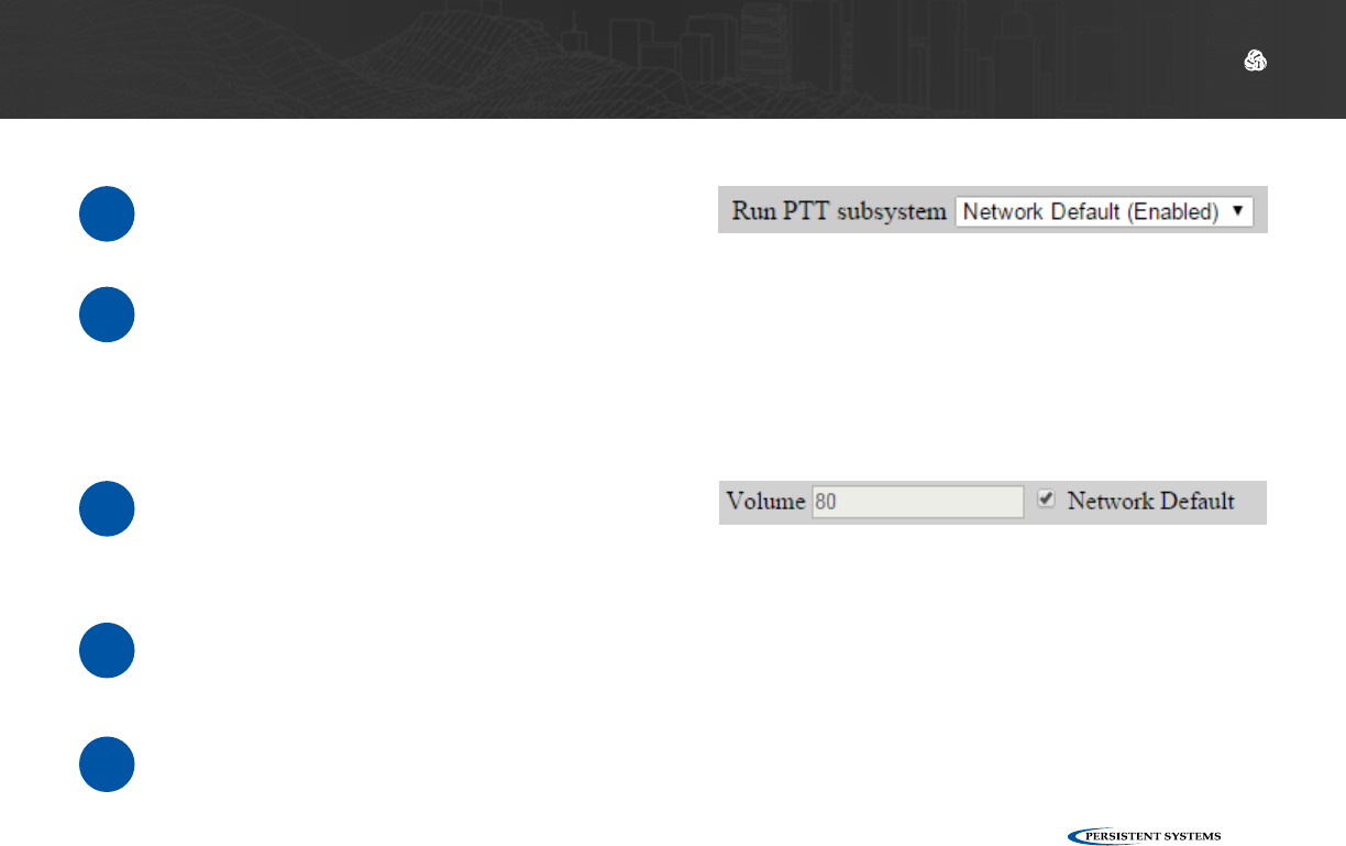
Set Earpiece Volume
1Next to Volume, check the Network De-
fault box to use the Network Default ear-
piece volume.
Enable Push-to-Talk
1In the Run PTT Subsystem drop-down
menu, select Enabled.
2To disable Push-to-Talk, select Disabled.
2To customize earpiece volume, uncheck
the Network Default box.
3In the Volume field, enter a value 0 - 125.
Values above 100 are digitally amplified.
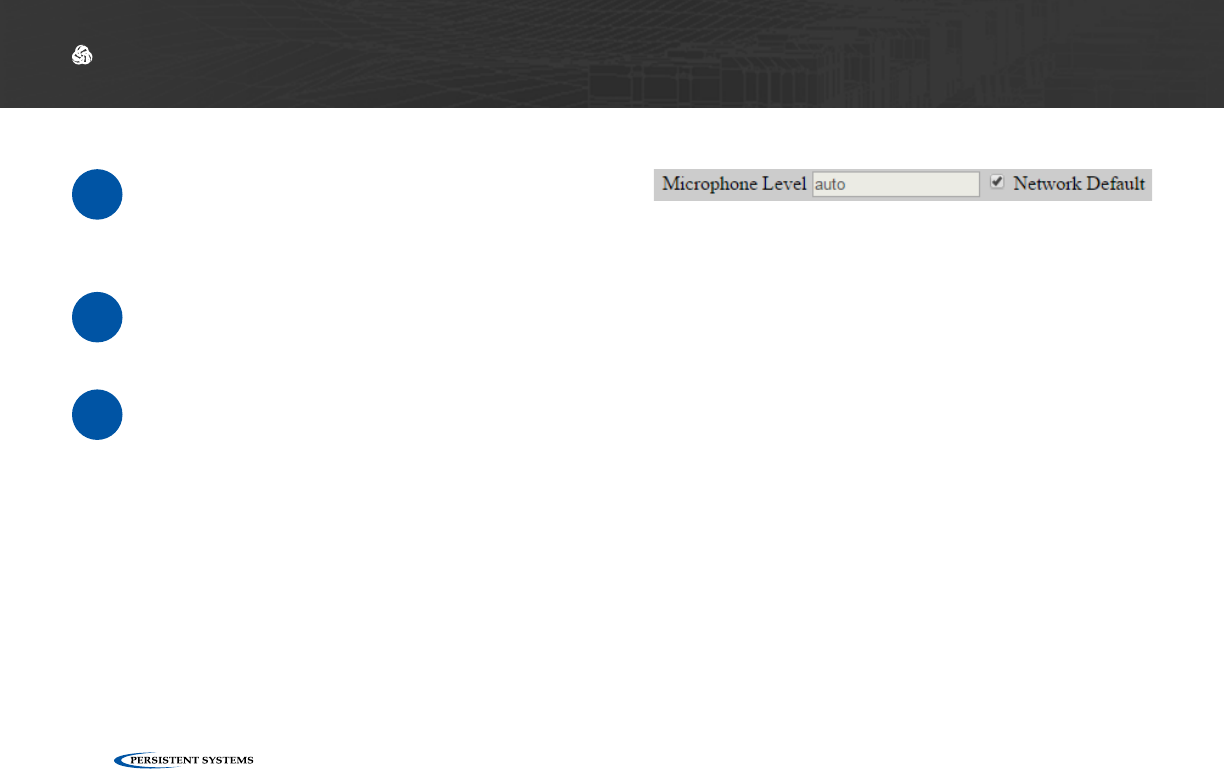
© 2010 - 2018 Persistent Systems, LLC – All Rights Reserved
132
DEVICE OPERATION: CONFIGURING PTT SETTINGS
Set Microphone Level
1Next to Microphone Level, check the Net-
work Default box to use the Network De-
fault microphone level.
2To customize microphone level, uncheck the
Network Default box.
3In the Microphone Level field, enter a val-
ue:
auto: Uses automatic gain control for mi-
crophone input - recommended for most
users
0 - 100: valid microphone level volumes
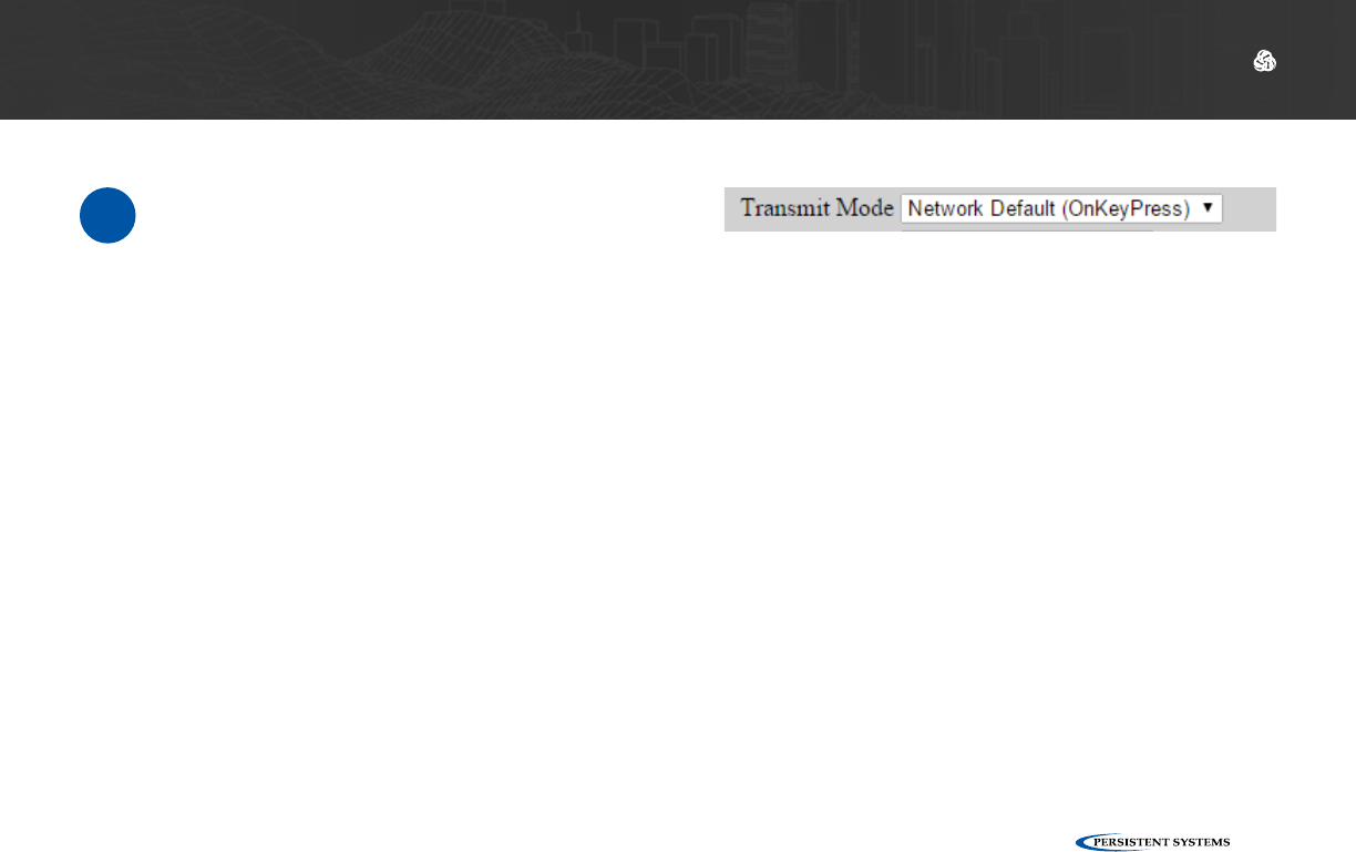
© 2010 - 2018 Persistent Systems, LLC – All Rights Reserved 133
DEVICE OPERATION: CONFIGURING PTT SETTINGS
Set Transmit Mode
1Select a setting from the Transmit Mode
drop-down menu:
OnKeyPress: audio is transmitted only
when the PTT button is pressed on the
headset
Continuous: audio is continuously trans-
mitted.
Note: other nodes may monitor
the channel only. Selected Channel
audio transmissions will interrupt
monitored continuously transmitted
audio.
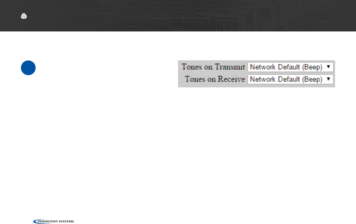
© 2010 - 2018 Persistent Systems, LLC – All Rights Reserved
134
DEVICE OPERATION: CONFIGURING PTT SETTINGS
Set Transmit or Receive Audible Checktone
1From the Tones on Transmit and Tones on
Receive drop down menus, select:
Quiet: no audible checktone
Beep: audible checktone will be set to a
beep
Voice: audible checktone will be a vocal-
ized “one”
Network Default: audible checktone will
be set to the network default setting
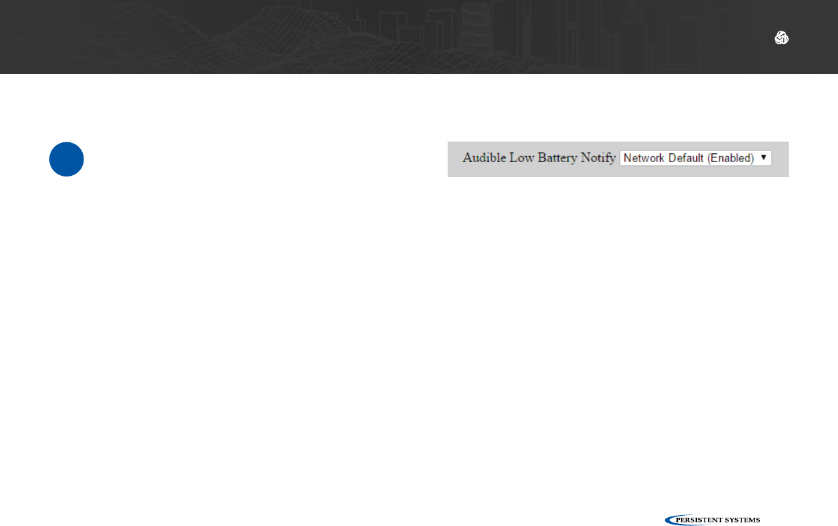
© 2010 - 2018 Persistent Systems, LLC – All Rights Reserved 135
DEVICE OPERATION: CONFIGURING PTT SETTINGS
Enable/Disable Low Battery Audible Notification
1Select a setting in the Low Battery drop-
down menu:
Enabled: when the battery is depleted to
5%, the node will play an audible notifica-
tion every 5 minutes.
Disabled: no low battery audible notifica-
tion will occur.
Network Default: network default set-
ting

© 2010 - 2018 Persistent Systems, LLC – All Rights Reserved
136
DEVICE OPERATION: CONFIGURING PTT SETTINGS
Selecting Channels
1In the Selected column, click the circle for the channel(s) you wish to transmit on.
2In the Monitor column, check the box for each channel you wish to monitor. You will be able
to hear PTT audio on the monitored channel.
Pro Tip: you may select any number of channels to monitor. In the Monitor column, check
the box for each channel you wish to monitor. You will NOT be able to transmit PTT audio on
channels other than the one you selected in Step 3.
Customize a PTT Channel
3In the Channel field, uncheck the Network Default box and enter the desired channel name.
4In the Multicast Address field, uncheck the Network Default box and enter the desired mul-
ticast address and multicast port in the form <multicast address>:<multicast port>.
Note: valid multicast address values are in the range 224.0.0.0 - 239.255.255.255
Note: valid multicast port values are in the range 1 - 65534
Note: each channel MUST have a unique multicast address and multicast port.
5Scroll to the bottom of the page and click Save.
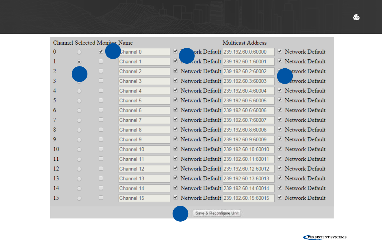
© 2010 - 2018 Persistent Systems, LLC – All Rights Reserved 137
DEVICE OPERATION: CONFIGURING PTT SETTINGS
1
23
4
5

© 2010 - 2018 Persistent Systems, LLC – All Rights Reserved
138
DEVICE OPERATION: CONFIGURING PTT SETTINGS
Using Wave Relay® Push-to-Talk
1Ensure that your PTT device is connected and channel settings have been configured proper-
ly and as desired.
2Press and hold the PTT button on the PTT device.
3Wait to hear a single beep.
4Talk.
5Release the PTT button when you are finished talking.
▶You may talk or listen, but you may not do both simultaneously.
▶Transmissions from an individual user are broadcast to all other users on the network using the
same channel.
▶Only one person may talk on a channel at one time. If you try to PTT while another user is trans-
mitting, you will hear a busy signal.
▶Selected Channel audio will interrupt Monitored Channel audio.
▶Flash Override audio will interrupt both Selected Channel and Monitored Channel audio.

© 2010 - 2018 Persistent Systems, LLC – All Rights Reserved 139
DEVICE OPERATION: CONFIGURING PTT SETTINGS
Using Flash Override
1To activate Flash Override, “tap-tap-hold” the PTT button (press and release the PTT button
quickly in succession, then press and hold the PTT button for the duration of the transmis-
sion)
2The transmitting user and all receiving users will hear three beeps.
3Talk.
4Release the PTT button when you are finished talking.
Flash Override is a feature that allows a user to transmit audio to all nodes on the network regard-
less of which channel they are operating on.
Flash Override audio will interrupt all audio on all channels.

© 2010 - 2018 Persistent Systems, LLC – All Rights Reserved
140
PROFESSIONAL INSTALLER – COMPLIANCE
The following notes refer to these part numbers:
Persistent Systems P/N Description FCC ID IC ID
RF-2100 S-Band Radio Module 2AG3J-RF2100 20968-RF2100
RF-5100 Upper C-Band Radio Module 2AG3J-RF5100 20968-RF5100
This device complies with part 15 of the FCC rules and Industry Canada license-exempt RSS stan-
dard(s). Operation is Subject to the following two conditions: (1) this device may not cause interfer-
ence, and (2) this device must accept any interference, including interference that may cause unde-
sired operation of the device.
Le présent appareil est conforme aux la partie 15 des règles de la FCC et CNR d’Industrie Canada
applicables aux appareils radio exempts de licence. L’exploitation est autorisée aux deux condi-
tions suivantes : (1) l’appareil ne doit pas produire de brouillage, et (2) l’utilisateur de l’appareil doit
accepter tout brouillage radioélectrique subi, même si le brouillage est susceptible d’en comprom-
ettre le fonctionnement.

© 2010 - 2018 Persistent Systems, LLC – All Rights Reserved 141
PROFESSIONAL INSTALLER – COMPLIANCE
NOTE: THE MANUFACTURER IS NOT RESPONSIBLE FOR ANY RADIO OR TV INTERFERENCE
CAUSED BY UNAUTHORIZED MODIFICATIONS TO THIS EQUIPMENT. SUCH MODIFICATIONS
COULD VOID THE USER’S AUTHORITY TO OPERATE THE EQUIPMENT.
NOTE II: This equipment has been tested and found to comply with the limits for a Class B digital
device, pursuant to Part 15 of the FCC Rules. These limits are designed to provide reasonable
protection against harmful interference when the equipment is operated in a commercial envi-
ronment. This equipment generates, uses, and can radiate radio frequency energy and, if not
installed and used in accordance with the instruction manual, may cause harmful interference to
radio communications. Operation of this equipment in a residential area is likely to cause harm-
ful interference in which case the user will be required to correct the interference at their own
expense.
OPERATING FREQUENCY: Operating frequency is determined by the installer. It is important that
the frequency configured meets local regulations.

© 2010 - 2018 Persistent Systems, LLC – All Rights Reserved
142
PROFESSIONAL INSTALLER – COMPLIANCE
US and Canada Power Limits
Mode: SISO: Only One Port Active MIMO (2x2): 2 Ports Active
Power Setting / Port
MIMO (3x3): All 3 Ports Active
Power Setting / Port
CHANNEL: Max. Power Setting
Approved (dBm)
Max. EIRP
(dBm)
Max. Power Setting
Approved (dBm)
Max. EIRP
(dBm)
Max. Power Setting
Approved (dBm)
Max. EIRP
(dBm)
1 28 32 26 31 24.5 31
2 30 35 26 32 24.5 31
3 30 36 26 32 24.5 31
4 30 36 26 32 24.5 31
5 30 36 26 32 24.5 31
6 30 36 26 32 24.5 31
7 30 36 26 32 24.5 31
8 30 36 26 32 24.5 31
9 30 36 26 32 24.5 31
10 30 33 26 32 24.5 31
11 29 32 26 31 24.5 31
P/N: RF-2100
FCC ID: 2AG3J-RF2100
IC ID: 20968-RF2100

© 2010 - 2018 Persistent Systems, LLC – All Rights Reserved 143
PROFESSIONAL INSTALLER – COMPLIANCE
Antenna Type and Gain (dBi): Omnidirectional / 3.5 dBi
USA Canada
Freq
(MHz)
Channel
(WLAN)
Channel
Width
(MHz)
SISO Max.
Power
Setting
Approved
(dBm)
2x2 Max.
Power
Setting
Approved
(dBm)
3x3 Max.
Power
Setting
Approved
(dBm)
Max. EIRP
Approved
(dBm)
SISO
Max.
Power
Approved
(dBm)
2x2 Max.
Power
Approved
(dBm)
3x3 Max.
Power
Approved
(dBm)
Max. EIRP
Approved
(dBm)
5180 36 20 17.0 14.0 11.5 21 n/a n/a n/a n/a
5200 44 20 17.0 14.0 11.5 21 n/a n/a n/a n/a
5240 48 20 17.0 14.0 12.0 21 n/a n/a n/a n/a
5745 149 20 29.5 26.5 24 36 29.5 26.5 24 36
5787 157 20 29.5 26.5 24 36 29.5 26.5 24 36
5825 165 20 29.5 26.5 24 36 29.5 26.5 24 36
P/N: RF-5100
FCC ID: 2AG3J-RF5100
IC ID: IC ID: 20968-RF5100

© 2010 - 2018 Persistent Systems, LLC – All Rights Reserved
144
PROFESSIONAL INSTALLER – COMPLIANCE
Operations outside of the FCC grant will require special licensing.
Approved Antennas:
The radio transmitters listed in the table below have been approved by Industry Canada to operate
with the antenna types listed below with the maximum permissible gain indicated. Antenna types
not included in this list, having a gain greater than the maximum gain indicated for that type, are
strictly prohibited for use with this device.
Part Number FCC ID IC ID Antenna Type Max. Gain Approved
(dBi)
RF-2100 2AG3J-RF2100 20968-RF2100 Omni 7.4
RF-5100 2AG3J-RF5100 20968-RF5100 Omni 3.5
EIRP (Isotropic Radiated Power) = Power Setting + Antenna Gain - Cable Loss
National regulations may require that operations may be limited to portions of the frequency range
shown in the channel selection page of the interface.

© 2010 - 2018 Persistent Systems, LLC – All Rights Reserved 145
PROFESSIONAL INSTALLER – COMPLIANCE
Minimum Safe Distance (MSD)
Antenna Gain (dBi) *Occupational Expo-
sure Distance (cm)
Non Occupational Ex-
posure Distance (cm)
Dipole (Omnidirec-
tional)
2.1 7.0 20.0
3.5 7.0 20.0
4.0 8.0 20.0
7.4 **11.0 **25
In addressing the MSD for operation of the RF-2100 S-Band (2200 MHz – 2500 MHz) radio module with FCC ID
2AG3J-RF2100 and IC ID 20968-RF2100 and the RF-5100 Upper C-Band (5100 MHz – 6000 MHz) radio module with
FCC ID 2AG3J-RF5100 and IC ID 20968-RF5100, the applicable Maximum Permissible Exposure (MPE) limits were
obtained IAW the FCC rules for radio frequency radiation exposure limits under
FCC Title 47, Chapter 1 Subpart 1
Article 1.1310 and Industrial Canada RSS-102, Section 2.6
.
En abordant la MSD pour le fonctionnement des RF-2100 S-Band (2200 MHz - 2500 MHz) module radio avec FCC
ID 2AG3J-RF2100 et IC ID 20968-RF2100 et RF-5100 Upper C-Band (5100 MHz – 6000 MHz) avec FCC ID 2AG3J-
RF5100 et IC ID 20968-RF5100, l’exposition maximale admissible applicable (MPE) limites ont été obtenus con-
formément à la FCC règles pour les limites d’exposition aux radiations de fréquences radio sous FCC Titre 47,
Chapitre 1 partie 1 article 1,1310 et industriel Canada RSS-102, Section 2.6.
For compliance information, contact Persistent Systems’ Quality Management Department.
Pour plus d’informations de conformité, le service de qualité contact Persistent Systems.
(212)-561-5895
support@persistentsystems.com

© 2010 - 2018 Persistent Systems, LLC – All Rights Reserved
146
PROFESSIONAL INSTALLER – COMPLIANCE
Notes:
*Occupational/controlled exposure limits apply in situations in which persons are exposed as a con-
sequence of their employment provided those persons are fully aware of the potential for exposure
and can exercise control over their exposure. Limits for occupational/controlled exposure also apply
in situations when a person is transient through a location where occupational/controlled limits
apply provided he or she is made aware of the potential for exposure. The phrase
fully aware
in the
context of applying these exposure limits means that an exposed person has received written and/
or verbal information fully explaining the potential for RF exposure resulting from his or her employ-
ment. With the exception of
transient
persons, this phrase also means that an exposed person has
received appropriate training regarding work practices relating to controlling or mitigating his or
her exposure. Such training is not required for
transient
persons, but they must receive written and/
or verbal information and notification (for example, using signs) concerning their exposure poten-
tial and appropriate means available to mitigate their exposure. The phrase
exercise control
means
that an exposed person is allowed to and knows how to reduce or avoid exposure by administrative
or engineering controls and work practices, such as use of personal protective equipment or time
averaging of exposure.
** Cable loss is the minimum cable loss that may exist between the antenna port and the 7.4dBi
antenna. 0.50dB cable loss was taken into consideration when calculating minimum distance.

© 2010 - 2018 Persistent Systems, LLC – All Rights Reserved 147
PROFESSIONAL INSTALLER – COMPLIANCE
Country: Japan (Government)
Mode of Operation: MIMO 3x3
Antenna Types and Gain (dBi)
Antenna 1: Omnidirectional / 3.5 dBi Antenna 2: Blade / 9 dBi Antenna 3: Patch 4x4 / 13 dBi
Japan Power Limits
Channel
(MHz)
Channel Width
(MHz)
Antenna 1 Antenna 2 Antenna 3
Max. Power Ap-
proved (dBm)
Max. EIRP Ap-
proved (dBm)
Max. Power Ap-
proved (dBm)
Max. EIRP Ap-
proved (dBm)
Max. Power Ap-
proved (dBm)
Max. EIRP Ap-
proved (dBm)
5660 20 25.2 36 22.2 36 18.2 36
5655 10 25.2 36 22.2 36 18.2 36
5665 10 25.2 36 22.2 36 18.2 36
5675 10 25.2 36 22.2 36 18.2 36
5680 20 25.2 36 22.2 36 18.2 36
5685 10 25.2 36 22.2 36 18.2 36
5695 10 25.2 36 22.2 36 18.2 36
5700 20 25.2 36 22.2 36 18.2 36
5705 10 25.2 36 22.2 36 18.2 36
5715 10 25.2 36 22.2 36 18.2 36
5720 20 25.2 36 22.2 36 18.2 36
5725 10 25.2 36 22.2 36 18.2 36
5740 10 25.2 36 22.2 36 18.2 36
5745 20 25.2 36 22.2 36 18.2 36
5750 10 25.2 36 22.2 36 18.2 36

© 2010 - 2018 Persistent Systems, LLC – All Rights Reserved
148
ATTACHMENTS
BAT-06 Technical Datasheet
Rechargeable, Lithium-Ion Battery
Features
• Communicates using a Single Wire DQ interface.
• UN/DOT 38.3 Rating: 73Wh
• Comparable to: BT-70716BE
Typical Applications
• Wave Relay System
• AN/PRC-148
• TRC-9110
Recommended Charging Platforms
Charger Part Number Required Adapter Part Number
BTC-70801 BTA-70810
BTC-70844 BTA-70810
BTC-70819, -1, -3 BTA-70810
BTC-70836 BTA-70830, BTA-70830-1
BTC-70870, -1, -3 BTA-70830, BTA-70830-2
BTC-70824-1 BTA-70810S
BTC-70663 BTA-70810S
BTC-70716-1 Not Required

© 2010 - 2018 Persistent Systems, LLC – All Rights Reserved 149
ATTACHMENTS
Technical Specifications
National Stock Number Pending
BT Part Number BT-70716BG
Dimensions
Length: 2.8 in. (71 mm) Width: 1.6 in.
(41 mm)
Height: 3.4 in. (86 mm)
Weight 0.75 lbs (0.34 kg)
Nominal Voltage 10.8V
Maximum Voltage 12.6V
Capacity 6.4Ah
Discharge 6A Max Continuous
Pulse Discharge 40A ≤ 1 ms
Operating Temperature -30°C to +60°C (-22°F to +140°F)
Recommended Storage Temperature -40°C to +40°C (-40°F to +104°F)
Connector Flat Contacts (bottom), Fly Wheel
Connection (top)
State of Charge Indicator Not Applicable
Disposal Check local regulations (Contains 0%
Mercury or Cadmium)

© 2010 - 2018 Persistent Systems, LLC – All Rights Reserved
150
ATTACHMENTS
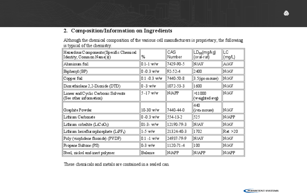
© 2010 - 2018 Persistent Systems, LLC – All Rights Reserved 151
ATTACHMENTS
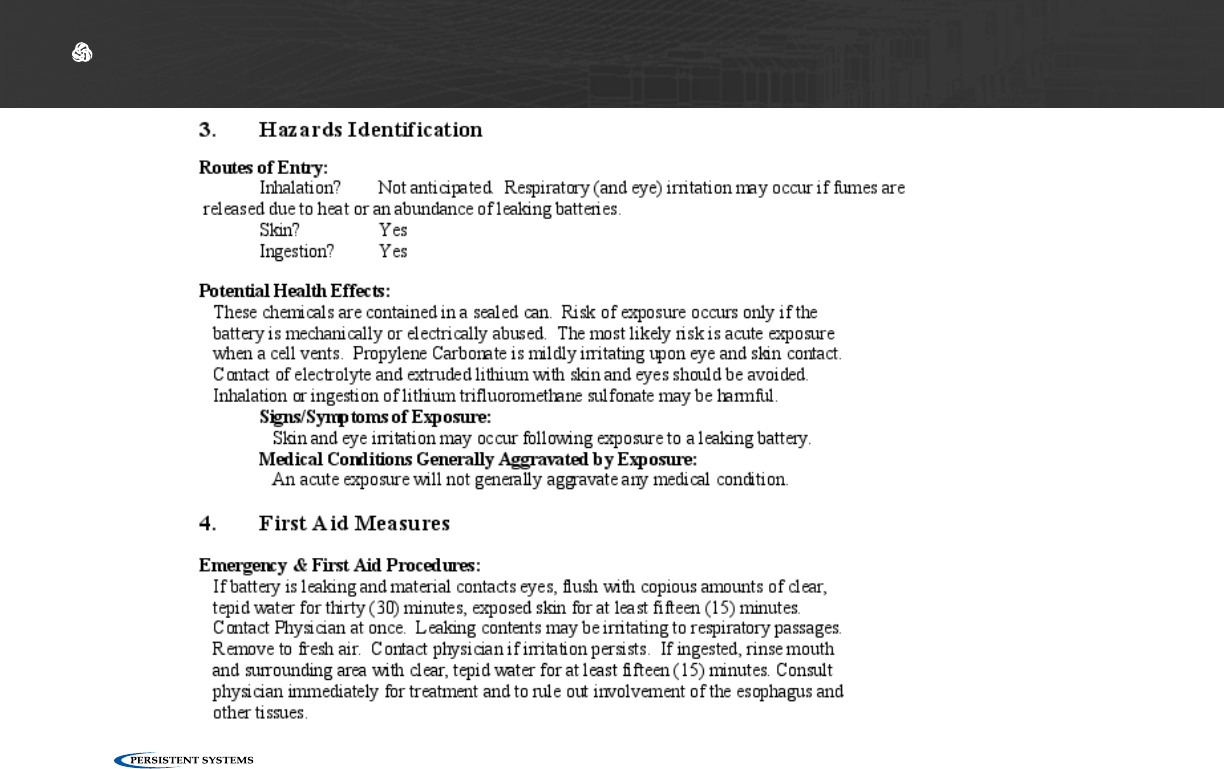
© 2010 - 2018 Persistent Systems, LLC – All Rights Reserved
152
ATTACHMENTS
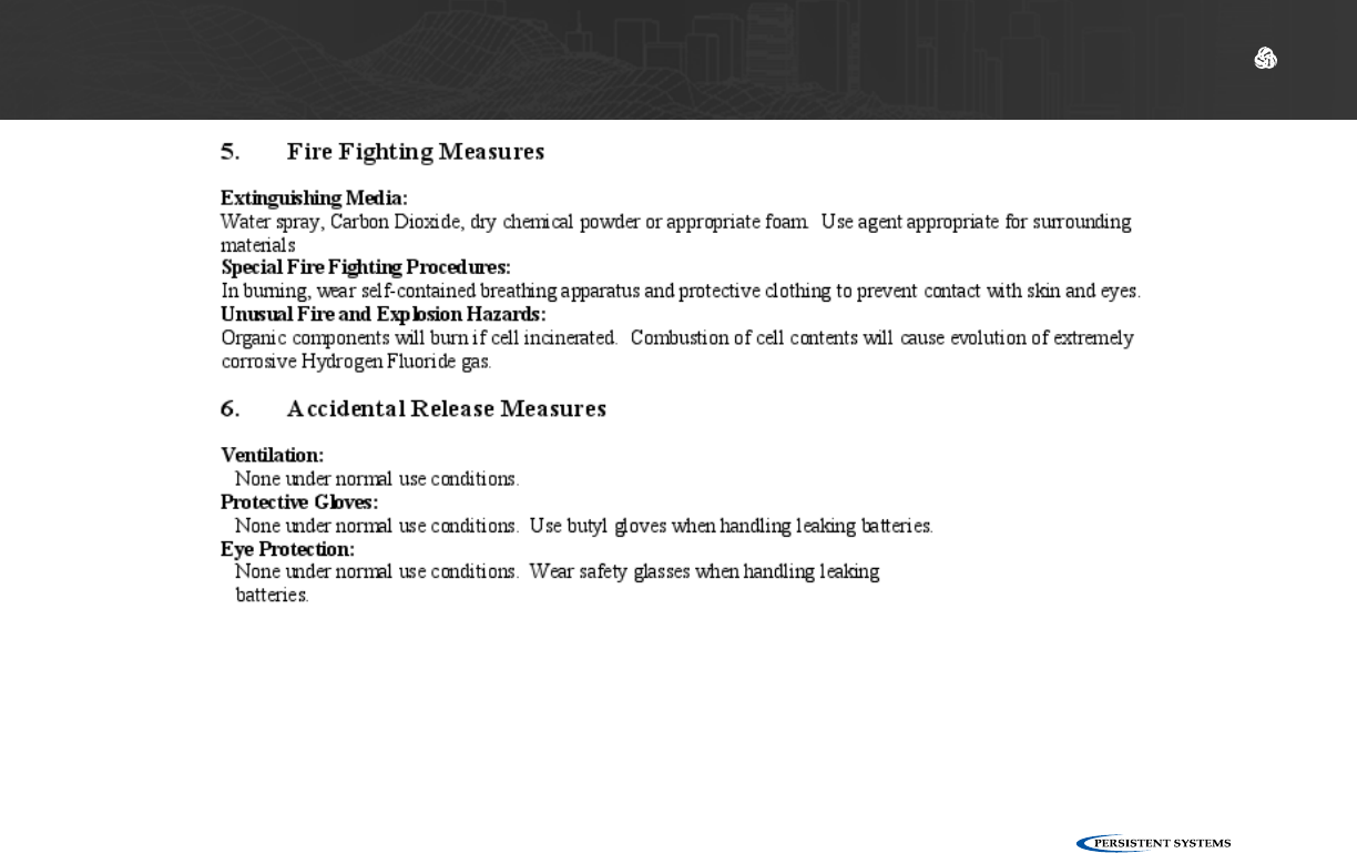
© 2010 - 2018 Persistent Systems, LLC – All Rights Reserved 153
ATTACHMENTS

© 2010 - 2018 Persistent Systems, LLC – All Rights Reserved
154
ATTACHMENTS

© 2010 - 2018 Persistent Systems, LLC – All Rights Reserved 155
ATTACHMENTS
© 2010 - 2018 Persistent Systems, LLC – All Rights Reserved
156
ATTACHMENTS

© 2010 - 2018 Persistent Systems, LLC – All Rights Reserved 157
ATTACHMENTS

MPU5
BASIC OPERATOR MANUAL
VERSION 2.5
303 Fifth Avenue Suite 306
New York, NY 10016
www.persistentsystems.com