Philips Electronics Singapore RC140A RF Remote control User Manual Onkyo TX NR901 Instruction Manual
Philips Electronics Singapore Pte Ltd RF Remote control Onkyo TX NR901 Instruction Manual
UserManual.wiki
>
Philips Electronics Singapore
>
RC140A User Manual
Users manual
Navigation menu
Upload a User Manual
Namespaces
Wiki Guide
HTML
PDF
Info
Views
User Manual
Discussion / Help
Navigation
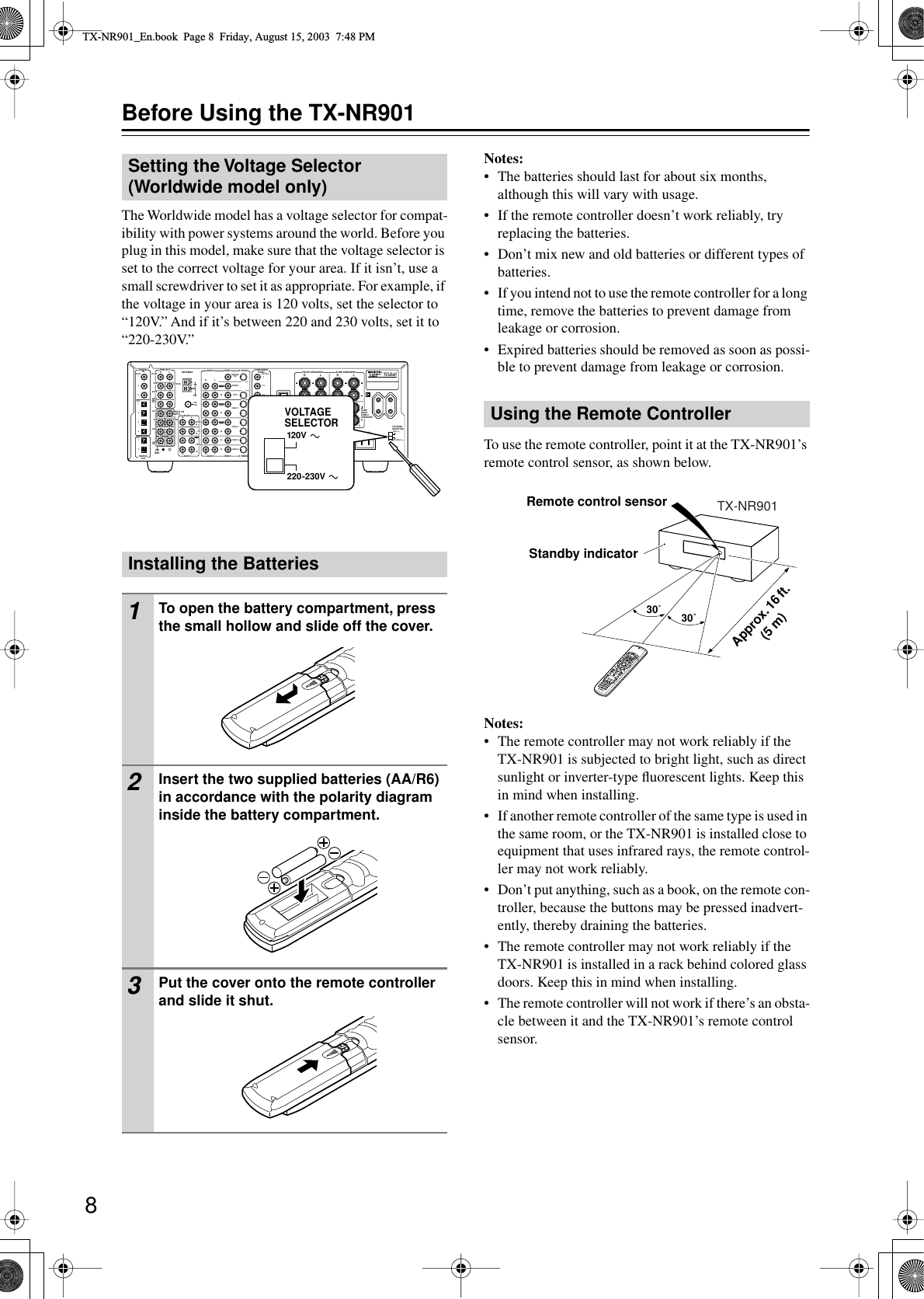
![3 Precautions For U.S. Models Note to CATV system installer: This reminder is provided to call the CATV system installer’s attention to Section 820-40 of the NEC which provides guidelines for proper grounding and, in partic-ular, specifies that the cable ground shall be connected to the grounding system of the building, as close to the point of cable entry as practical. FCC Information for User CAUTION: The user changes or modifications not expressly approved by the party responsible for compliance could void the user’s authority to operate the equipment. NOTE: This equipment has been tested and found to comply with the limits for a Class B digital device, pursuant to Part 15 of the FCC Rules.These limits are designed to provide reasonable protec-tion against harmful interference in a residential instal-lation. This equipment generates, uses and can radiate radio frequency energy and, if not installed and used in accordance with the instructions, may cause harmful interference to radio communications. However, there is no guarantee that interference will not occur in a partic-ular installation.If this equipment does cause harmful interference to radio or television reception, which can be determined by turning the equipment off and on, the user is encour-aged to try to correct the interference by one or more of the following measures: • Reorient or relocate the receiving antenna.• Increase the separation between the equipment and receiver.•Connect the equipment into an outlet on a circuit different from• that to which the receiver is connected.• Consult the dealer or an experienced radio/TV technician for help. For Canadian model NOTE: This class B digital apparatus complies with Canadian ICES-003.For models having a power cord with a polarized plug: CAUTION: TO PREVENT ELECTRIC SHOCK, MATCH WIDE BLADE OF PLUG TO WIDE SLOT, FULLY INSERT. Modèle pour les Canadien REMARQUE: Cet appareil numérique de la classe B est conforme à la norme NMB-003 du Canada.Sur les modèles dont la fiche est polarisee: ATTENTION: POUR ÉVITER LES CHOCS ÉLEC-TRIQUES, INTRODUIRE LA LAME LA PLUS LARGE DE LA FICHE DANS LA BORNE CORRE-SPONDANTE DE LA PRISE ET POUSSER JUSQU’AU FOND. 1. Recording Copyright —Unless it’s for personal use only, recording copyrighted material is illegal with-out permission of the copyright holder. 2. AC Fuse — The AC fuse inside the TX-NR901 is not user-serviceable. If you cannot turn on the TX-NR901, contact your Onkyo dealer. 3. Care —Occasionally you should dust the TX-NR901 all over with a soft cloth. For stubborn stains, use a soft cloth dampened with a weak solu-tion of mild detergent and water. Dry the TX-NR901 immediately afterwards with a clean cloth. Don’t use abrasive cloths, thinners, alcohol, or other chemical solvents, because they may dam-age the finish or remove the panel lettering. 4. PowerWARNING BEFORE PLUGGING IN THE UNIT FOR THE FIRST TIME, READ THE FOLLOWING SECTION CAREFULLY.AC outlet voltages vary from country to country. Make sure that the voltage in your area meets the voltage requirements printed on the TX-NR901’s rear panel (e.g., AC 230 V, 50 Hz or AC 120 V, 60 Hz).The Worldwide model has a voltage selector for com-patibility with power systems around the world. Before you plug in this model, make sure that the voltage selec-tor is set to the correct voltage for your area. For North American model Setting the [STANDBY/ON] switch to STANDBY does not fully shutdown the TX-NR901. If you do not intend to use the TX-NR901 for an extended period, remove the power cord from the AC outlet. TX-NR901_En.book Page 3 Friday, August 15, 2003 7:48 PM](https://usermanual.wiki/Philips-Electronics-Singapore/RC140A/User-Guide-375129-Page-3.png)
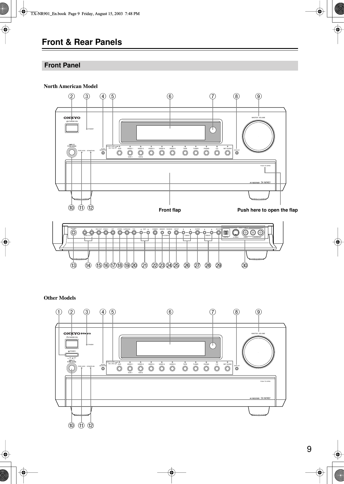
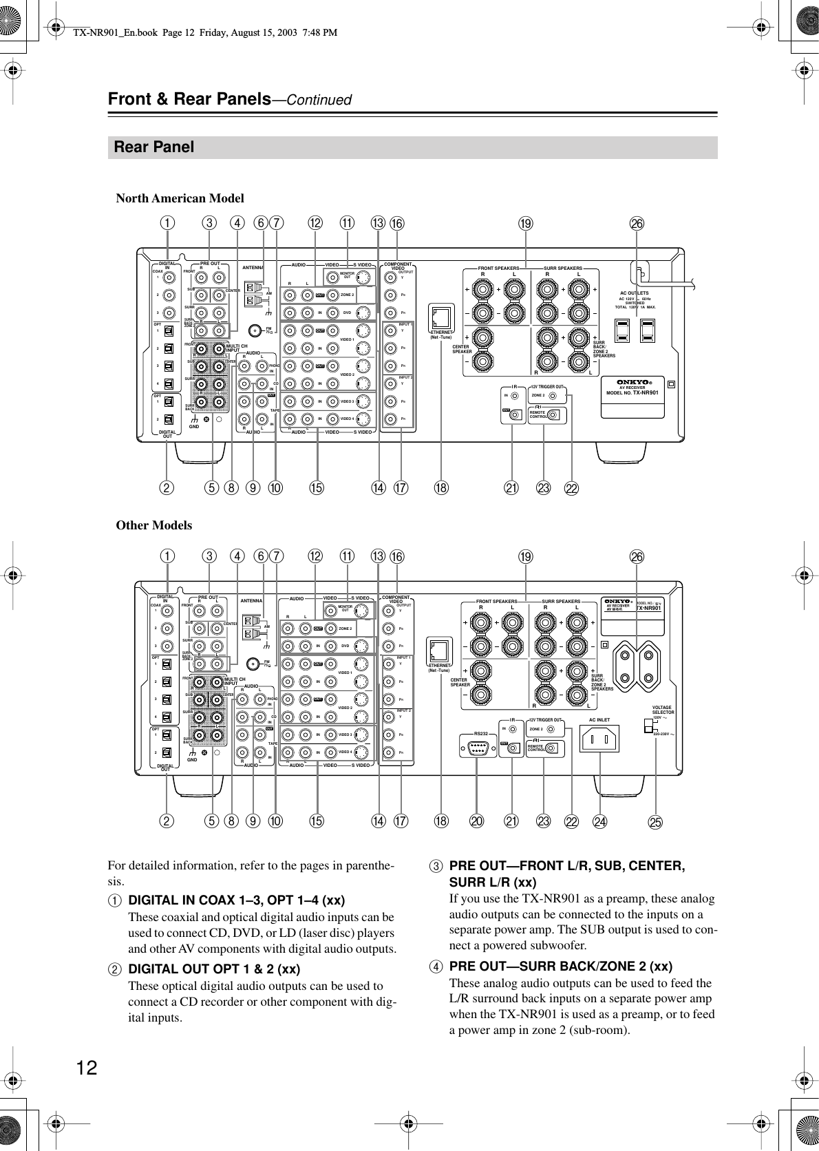
![10 Front & Rear Panels —Continued For detailed information, refer to the pages in parenthe-sis. A POWER switch (xx) North American and Australian models don’t have this switch.This is the main power switch. When set to OFF, the TX-NR901 is completely shutdown. When set to ON, the TX-NR901 is in Standby mode and the STANDBY indicator lights up.Don’t turn on the power until you’ve completed, and double checked all connections. Note: Turning on the TX-NR901 may cause a momentary power surge that might interfere with other electrical equipment on the same circuit. If this is a problem, plug the TX-NR901 into a different branch circuit. B STANDBY/ON button (xx) This button is used to set the TX-NR901 to On or Standby. For models with a POWER switch, this but-ton has no effect unless the POWER switch is set to ON. C STANDBY indicator (xx) This indicator lights up when the TX-NR901 is in Standby mode, and it flashes while a signal is being received from the remote controller. D AUDIO SELECTOR button (xx) This button is used to select the audio input signal format: analog, digital, or multi-channel. E Input selector buttons & indicators (xx) These buttons are used to select the following input sources: DVD, VIDEO 1–5, TAPE, TUNER, PHONO, CD, and NET AUDIO. The indicators show the currently selected input source.The indicators also show which input source is selected for zone 2 (sub-room), in which case they light up green, or which input source is selected for recording (REC OUT), in which case they light up red. F Display See “Display” on page 11. G Remote-control sensor (xx) This sensor receives control signals from the remote controller. H DISPLAY button (xx) This button is used to display various information about the currently selected input source. I MASTER VOLUME control (xx) This control is used to set the volume of the TX-NR901 from 0 to 100. J DIRECT/PURE AUDIO button (xx) This button is used to select the Direct and Pure Audio listening modes. K PURE AUDIO indicator (xx) This indicator lights up when the Pure Audio listen-ing mode is selected. L UPSAMPLING indicator (66) This indicator lights up when the Upsampling func-tion is on. M PHONES jack (xx) This 1/4-inch phone jack is for connecting a standard pair of stereo headphones for private listening. N ZONE 2 LEVEL [ ] [ ] buttons (xx) These buttons are used to set the volume in zone 2 (sub-room). O REC OUT button (62) This button is used to select the input source that you want to record via the REC OUTs (i.e., TAPE OUT, VIDEO 1 OUT, VIDEO 2 OUT). P ZONE 2 button (85) This button is used to select the input source that you want play in zone 2 (sub-room). QOFF button (62, 85)This button is used to turn off the REC OUTs (i.e., TAPE OUT, VIDEO 1 OUT, VIDEO 2 OUT) or zone 2.RSTEREO button (52)This button is used to select the Stereo listening mode.SSURROUND button (52)This button is used to select the Dolby and DTS lis-tening modes.TTHX button (52)This button is used to select the THX listening modes.UDSP [ ] [ ] buttons (52)These buttons are used to select the DSP (digital sig-nal processor) listening modes.VDIMMER button (xx)This button is used to adjust the display brightness.WMEMORY button (xx)This button is used when storing and deleting radio presets.XFM MODE button (xx)This button is used to select the FM radio Auto and Mono modes.YSETUP button (37, 64)This button is used to access the onscreen setup menus (OSD) that appear on the TV that’s connected to the composite video or S-Video MONITOR OUT.ZTUNING [ ] [ ] buttons (xx)These buttons are used to tune into radio stations and to select items on the onscreen setup menus (OSD).TX-NR901_En.book Page 10 Friday, August 15, 2003 7:48 PM](https://usermanual.wiki/Philips-Electronics-Singapore/RC140A/User-Guide-375129-Page-10.png)
![11aENTER buttonThis button is used when navigating the onscreen setup menus (OSD), entering names, and confirming settings.bPRESET [ ] [ ] buttons (xx)These buttons are used to select radio presets and to select items on the onscreen setup menus (OSD).cRETURN button (xx)This button is used to return to the previously dis-played onscreen setup menu (OSD).dVIDEO 5 INPUTs (xx)These optical digital audio, S-Video, composite video, and analog audio inputs can be used to con-nect a video camera, games console, and so on.For detailed information, refer to the pages in parenthe-sis.1Audio input format indicatorsThese indicators show the audio input format for the currently selected input source.2Listening mode & digital audio format indicatorsThese indicators show the currently selected listen-ing mode and digital audio format.3Tuning indicatorsAUTO indicator:This indicator lights up when the tuner is tuned to an FM station and Stereo mode is selected. It goes off when Mono mode is selected.TUNED indicator:This indicator lights up when the tuner is tuned into an AM or FM station.FM STEREO indicator:This indicator lights up when the tuner is tuned to a stereo FM station. It goes off when Mono mode is selected.4Multipurpose display areaNormally, the name of the currently selected input source is displayed here. When you select the AM or FM input source, the radio frequency and preset number are displayed. If you press the [DISPLAY] button, the currently selected listening mode and digital audio format are displayed.5Volume levelThe volume level is displayed here.6SLEEP indicatorThis indicator lights up when the Sleep function has been set.Display45631 2TX-NR901_En.book Page 11 Friday, August 15, 2003 7:48 PM](https://usermanual.wiki/Philips-Electronics-Singapore/RC140A/User-Guide-375129-Page-11.png)
![14Remote ControllerThe TX-NR901’s remote controller is a multipurpose device that can be used to control not just the TX-NR901 but your other AV components as well. This section explains how it’s various operating modes can be used to control the TX-NR901 and various -compatible Onkyo components. See page 87 for information on using the remote controller to control Onkyo compo-nents without and TVs, VCRs, and AV components made by other manufacturers.For detailed information, refer to the pages in parenthe-sis.Amp mode is used to control the TX-NR901. To select Amp mode, press the [MODE] button, and then roll the scroll wheel until “AMP” appears on the display.Boxed numbers are for Net-Tune mode (page 15).AON buttonThis button is used to turn on the TX-NR901.BSTANDBY buttonThis button is used to set the TX-NR901 to Standby.CNumber/letter buttonsThese buttons are used to enter numbers and letters.DCUSTOM buttonThis button is used to access various settings that you can use to customize the operation of the remote controller.EMACRO buttonThis button is used with the Macro function.FMODE buttonThis button is used with the scroll wheel to select the remote controller modes. Press this button first, and then roll the scroll wheel until “AMP” appears on the display.GDIMMER buttonThis button is used to adjust the display brightness.H[] [ ] [ ] [ ] & ENTER buttonsThese buttons are used to select items on the onscreen setup menus (OSD). The ENTER button is also used to enter names and to confirm settings.ICH/DISC +/– buttonThis button is used to select radio presets.JRETURN/EXIT buttonThis button is used to return to the previously dis-played onscreen setup menu (OSD).KDISPLAY buttonThis button is used to display various information about the currently selected input source.LTHX buttonThis button is used to select the THX listening modes.MSURR buttonThis button is used to select the Dolby and DTS lis-tening modes.NDIRECT buttonThis button is used to select the Direct listening mode.OPURE A buttonThis button is used to select the Pure Audio listening mode.Amp Mode--/---@. - ' /ABC DEFPQRS TUV WXYZDIRECT TUNINGGHI JKL MNOCAPS DELETELANGUAGE LOCATIONALBUM AR TIST GENREPLAYLISTCUSTOMDISPLAYDIMMERT V/ VIDEOSLEEPRANDOMRECSTEP / SLOWMUTINGENTERLAST MANGLESUBTITLEAUDIOMEMORYSEARCHA-BREPEATON STANDBY TVTV CHTV VOLRC-549MAUDIOADJEXITGUIDE+10 0CLEAR123456789INPUTTOPMENUMENUSETUPRETURNZONE 2INPUTMODEMACROVOLCHDISCTEST TONECH SELPURE ASURRDIRECTSTEREORe-EQTHXAll CH STLEVEL+LEVEL-L NIGHTAUDIO SELDSP DSP+-+-ACDEFGIHJMLONPQKBRTUSWYZacebdXV2134567890AScroll wheelTX-NR901_En.book Page 14 Friday, August 15, 2003 7:48 PM](https://usermanual.wiki/Philips-Electronics-Singapore/RC140A/User-Guide-375129-Page-14.png)
![15PTEST TONE, CH SEL, LEVEL– & LEVEL+ buttonsThese buttons are used to adjust the level of each speaker individually. These functions can be set only with the remote controller.QAUDIO SEL buttonThis button is used to select the audio input signal format: analog, digital, or multi-channel.RLIGHT buttonThis button is used to turn on or off the remote con-troller’s illuminated buttons.SDIRECT TUNING buttonThis button is used with the number buttons to select a radio station by entering its frequency. Press this button first, and then use the number buttons to enter the frequency.TDisplayThe top line of this LCD display shows the name of the currently selected input source. The bottom line shows the currently selected remote controller mode.UZONE 2 button (85)This button is used when you want to set the volume and input source for zone 2 (sub-room).VINPUT buttonThis button is used to select the input source. Press this button first, and then roll the scroll wheel until the name of the input source appears on the display.Note:While neither the [MODE] button nor [INPUT] but-ton is illuminated, rolling the scroll wheel changes both lines of the display.WSLEEP buttonThis button is used to set the Sleep function. This function can be set only with the remote controller.XVOL Up/Down [ ]/[ ] button (xx, 85)This button is used to set the volume of the TX-NR901. They can also be used to set the volume in zone 2 (sub-room).YSETUP/GUIDE buttonThis button is used to access the onscreen setup menus (OSD) that appear on the TV that’s connected to the composite video or S-Video MONITOR OUT.ZMUTING buttonThis button is used to mute the TX-NR901. This function can be set only with the remote controller.aAll CH ST buttonThis button is used to select the All Ch Stereo listen-ing mode.bSTEREO buttonThis button is used to select the Stereo listening mode.c[ DSP] & [DSP ] buttonsThese buttons are used to select the DSP (digital sig-nal processor) listening modes.dRe-EQ buttonThis button is used to turn on and off the Re-EQ function.eL NIGHT buttonThis button is used to set the Late Night function.Net-Tune mode is used with the Net-Tune functions. To select Net-Tune mode, press the [MODE] button, and then roll the scroll wheel until “NET-T” appears on the display.1Number/letter buttonsThese buttons are used to enter numbers and letters when searching for music in your Net-Tune Central music library.2MODE buttonThis button is used with the scroll wheel to select the remote controller modes. Press this button first, and then roll the scroll wheel until “NET-T” appears on the display.3ALBUM buttonThis button is used to search your Net-Tune Central music library by album.4PLAYLIST buttonThis button is used to search your Net-Tune Central library by playlist.5CAPS buttonThis button is used to select lowercase letters, upper-case letters, and numbers when searching for Net-Tune Central music by album, artist, or playlist.6DELETE buttonThis button is used to delete characters entered with the number/letter buttons.7INPUT buttonThis button is used to select the input source. Press this button first, and then roll the scroll wheel until “MSRV” (Music Server—Net-Tune Central) or “IRD” (Internet Radio) appears on the display.Note:While neither the [MODE] button nor [INPUT] but-ton is illuminated, rolling the scroll wheel changes both lines of the display.8ARTIST buttonThis button is used to search your Net-Tune Central music library by artist.9GENRE buttonThis button is used to search your Net-Tune Central music library by genre, and to search for Internet radio stations by genre.0LOCATION buttonThis button is used to search for Internet radio sta-tions by country.ALANGUAGE buttonThis button is used to search for Internet radio sta-tions by language.Net-Tune ModeTX-NR901_En.book Page 15 Friday, August 15, 2003 7:48 PM](https://usermanual.wiki/Philips-Electronics-Singapore/RC140A/User-Guide-375129-Page-15.png)
![16Remote Controller—ContinuedConnecting your -compatible Onkyo DVD player, CD player, MiniDisc recorder, or cassette recorder to the TX-NR901’s RI jack allows you to control it with the TX-NR901’s remote controller. Since you only need to point the remote controller at the TX-NR901, you can even control Onkyo components that are installed in a cabinet. See page 35 for connection information.To use the RI function, you must make an RI connection and an analog RCA/phono audio connection between the AV component and your TX-NR901, even if they are connected digitally.DVD mode is used to control an Onkyo DVD player con-nected to the TX-NR901 via . To select DVD mode, press the [MODE] button, and then roll the scroll wheel until “DVD” appears on the display.AON buttonThis button is used to turn on the DVD player.BSTANDBY buttonThis button is used to set the DVD player to Standby.CNumber/letter buttonsThese buttons are used to enter title, chapter, and track numbers and to enter times for locating specific points in time.DMODE buttonThis button is used with the scroll wheel to select the remote controller modes. Press this button first, and then roll the scroll wheel until “DVD” appears on the display.ETOP MENU buttonThis button is used to select the DVD-Video disc’s top menu.F[] [ ] [ ] [ ] & ENTER buttonsThese buttons are used to navigate DVD-Video menus and the DVD player’s onscreen setup menus. The ENTER button is used to start playback of the selected menu title, chapter, or track and to confirm settings.GCH/DISC +/– buttonThis button is used to select discs on a DVD changer.HRETURN/EXIT buttonThis button is used to exit the DVD player’s onscreen setup menu and to restart menu playback.IDISPLAY buttonThis button is used to display information about the current disc, title, chapter, or track, including the elapsed time, remaining time, total time, and so on.JPrevious/Next [ ]/[ ] buttonsThe Previous [ ] button is used to select the previ-ous chapter or track. During playback it selects the beginning of the current chapter or track. The Next [] button is used to select the next chapter or track.KFR/FF [ ]/[ ] buttonsThe FR [ ] button is used to start fast reverse. The FF [ ] button is used to start fast forward.LPause [ ] buttonThis button is used to pause DVD playback.MSTEP/SLOW [ ]/[ ] buttonsThese buttons are used for frame-by-frame playback and slow-motion playback.DVD Mode--/---@. - ' /ABC DEFPQRS TUV WXYZDIRECT TUNINGGHI JKL MNOCAPS DELETELANGUAGE LOCATIONALBUM AR TIST GENREPLAYLISTCUSTOMDISPLAYDIMMERT V/ VIDEOSLEEPRANDOMRECSTEP / SLOWMUTINGENTERLAST MANGLESUBTITLEAUDIOMEMORYSEARCHA-BREPEATON STANDBY TVTV CHTV VOLRC-549MAUDIOADJEXITGUIDE+10 0CLEAR123456789INPUTTOPMENUMENUSETUPRETURNZONE 2INPUTMODEMACROVOLCHDISCTEST TONECH SELPURE ASURRDIRECTSTEREORe-EQTHXAll CH STLEVEL+LEVEL-L NIGHTAUDIO SELDSP DSP+-+-ACDEFHGONLMPQRIJBSUWXYZbedcaVTKScroll wheelTX-NR901_En.book Page 16 Friday, August 15, 2003 7:48 PM](https://usermanual.wiki/Philips-Electronics-Singapore/RC140A/User-Guide-375129-Page-16.png)
![17Remote Controller—ContinuedNSUBTITLE buttonThis button is used to select subtitles.OAUDIO buttonThis button is used to select foreign language soundtracks and audio formats (e.g., Dolby Digital or DTS).PREPEAT buttonThis button is used to set the repeat playback func-tions.QA-B buttonThis button is used to set the A–B repeat playback function.ROpen/Close [ ] buttonThis button is used to open and close the disc tray.SLIGHT buttonThis button is used to turn on or off the remote con-troller’s illuminated buttons.TINPUT buttonThis button is used to select the input source. Press this button first, and then roll the scroll wheel until “DVD” appears on the display.Note:While neither the [MODE] button nor [INPUT] but-ton is illuminated, rolling the scroll wheel changes both lines of the display.UMENU buttonThis button is used to select the DVD-Video disc’s menu.VVOL Up/Down [ ]/[ ] button (xx)This button is used to set the volume of the TX-NR901.WSETUP/GUIDE buttonThis button is used to access the DVD player’s onscreen setup menus.XMUTING buttonThis button is used to mute the TX-NR901. This function can be set only with the remote controller.YPlay [ ] buttonThis button is used to start DVD playback.ZStop [ ] buttonThis button is used to stop DVD playback.aRANDOM buttonThis button is used with the random playback func-tion.bANGLE buttonThis button is used to select different camera angles.cLAST M buttonThis button is used with the last memory function, which allows you to resume DVD playback from where you left off.dMEMORY buttonThis button is used with the memory playback func-tion, which allows you to create a custom playlist of titles, chapters, or tracks.eSEARCH buttonThis button is used to search for titles, chapters, tracks, and specific points in time.TX-NR901_En.book Page 17 Friday, August 15, 2003 7:48 PM](https://usermanual.wiki/Philips-Electronics-Singapore/RC140A/User-Guide-375129-Page-17.png)
![18Remote Controller—ContinuedCD mode is used to control an Onkyo CD player con-nected to the TX-NR901 via . To select CD mode, press the [MODE] button, and then roll the scroll wheel until “CD” appears on the display.Boxed numbers are for MiniDisc mode (page 19).AON buttonThis button is used to turn on the CD player.BSTANDBY buttonThis button is used to set the CD player to Standby.CNumber/letter buttonsThese buttons are used to enter track numbers and to enter times for locating specific points in time.DMODE buttonThis button is used with the scroll wheel to select the remote controller modes. Press this button first, and then roll the scroll wheel until “CD” appears on the display.EENTER buttonThe ENTER button is used to confirm settings.FCH/DISC +/– buttonThis button is used to select discs on a CD changer.GDISPLAY buttonThis button is used to display information about the current disc or track, including the elapsed time, remaining time, total time, and so on.HPrevious/Next [ ]/[ ] buttonsThe Previous [ ] button is used to select the previ-ous track. During playback it selects the beginning of the current track. The Next [ ] button is used to select the next track.IFR/FF [ ]/[ ] buttonsThe FR [ ] button is used to start fast reverse. The FF [ ] button is used to start fast forward.JPause [ ] buttonThis button is used to pause CD playback.KREPEAT buttonThis button is used to set the repeat playback func-tions.LA-B buttonThis button is used to set the A–B repeat playback function.MOpen/Close [ ] buttonThis button is used to open and close the disc tray.NLIGHT buttonThis button is used to turn on or off the remote con-troller’s illuminated buttons.OINPUT buttonThis button is used to select the input source. Press this button first, and then roll the scroll wheel until “CD” appears on the display.Note:While neither the [MODE] button nor [INPUT] but-ton is illuminated, rolling the scroll wheel changes both lines of the display.PVOL Up/Down [ ]/[ ] button (xx)This button is used to set the volume of the TX-NR901.QMUTING buttonThis button is used to mute the TX-NR901. This function can be set only with the remote controller.CD Mode--/---@. - ' /ABC DEFPQRS TUV WXYZDIRECT TUNINGGHI JKL MNOCAPS DELETELANGUAGE LOCATIONALBUM AR TIST GENREPLAYLISTCUSTOMDISPLAYDIMMERT V/ VIDEOSLEEPRANDOMRECSTEP / SLOWMUTINGENTERLAST MANGLESUBTITLEAUDIOMEMORYSEARCHA-BREPEATON STANDBY TVTV CHTV VOLRC-549MAUDIOADJEXITGUIDE+10 0CLEAR123456789INPUTTOPMENUMENUSETUPRETURNZONE 2INPUTMODEMACROVOLCHDISCTEST TONECH SELPURE ASURRDIRECTSTEREORe-EQTHXAll CH STLEVEL+LEVEL-L NIGHTAUDIO SELDSP DSP+-+-A3456JKLM78NQRSVUTPO91234567890ABCDFEGIHJBScroll wheelTX-NR901_En.book Page 18 Friday, August 15, 2003 7:48 PM](https://usermanual.wiki/Philips-Electronics-Singapore/RC140A/User-Guide-375129-Page-18.png)
![19Remote Controller—ContinuedRPlay [ ] buttonThis button is used to start CD playback.SStop [ ] buttonThis button is used to stop CD playback.TRANDOM buttonThis button is used with the random playback func-tion.UMEMORY buttonThis button is used with the memory playback func-tion, which allows you to create a custom playlist of tracks.VSEARCH buttonThis button is used to search for tracks and specific points in time.MiniDisc mode is used to control an Onkyo MiniDisc recorder connected to the TX-NR901 via . To select MiniDisc mode, press the [MODE] button, and then roll the scroll wheel until “MD” appears on the display.1ON buttonThis button is used to turn on the MiniDisc recorder.2STANDBY buttonThis button is used to set the MiniDisc recorder to Standby.3Number/letter buttonsThese buttons are used to enter track numbers and to enter times for locating specific points in time.4MODE buttonThis button is used with the scroll wheel to select the remote controller modes. Press this button first, and then roll the scroll wheel until “MD” appears on the display.5ENTER buttonThe ENTER button is used to confirm settings.6DISPLAY buttonThis button is used to display information about the current disc or track, including the elapsed time, remaining time, total time, and so on.7Previous/Next [ ]/[ ] buttonsThe Previous [ ] button is used to select the previ-ous track. During playback it selects the beginning of the current track. The Next [ ] button is used to select the next track.8FR/FF [ ]/[ ] buttonsThe FR [ ] button is used to start fast reverse. The FF [ ] button is used to start fast forward.9Pause [ ] buttonThis button is used to pause MiniDisc playback.0REC [ ] buttonThis button is used to start MiniDisc recording.AREPEAT buttonThis button is used to set the repeat playback func-tions.BEject [ ] buttonThis button is used to set eject the MiniDisc.CLIGHT buttonThis button is used to turn on or off the remote con-troller’s illuminated buttons.DINPUT buttonThis button is used to select the input source. Press this button first, and then roll the scroll wheel until “MD” appears on the display.Note:While neither the [MODE] button nor [INPUT] but-ton is illuminated, rolling the scroll wheel changes both lines of the display.EVOL Up/Down [ ]/[ ] button (xx)This button is used to set the volume of the TX-NR901.FMUTING buttonThis button is used to mute the TX-NR901. This function can be set only with the remote controller.GPlay [ ] buttonThis button is used to start MiniDisc playback.HStop [ ] buttonThis button is used to stop MiniDisc playback.IRANDOM buttonThis button is used with the random playback func-tion.JMEMORY buttonThis button is used with the memory playback func-tion, which allows you to create a custom playlist of tracks.MiniDisc ModeTX-NR901_En.book Page 19 Friday, August 15, 2003 7:48 PM](https://usermanual.wiki/Philips-Electronics-Singapore/RC140A/User-Guide-375129-Page-19.png)
![20Remote Controller—ContinuedTape mode is used to control an Onkyo cassette recorder connected to the TX-NR901 via . To select Tape mode, press the [MODE] button, and then roll the scroll wheel until “AMP” appears on the display.AMODE buttonThis button is used with the scroll wheel to select the remote controller modes. Press this button first, and then roll the scroll wheel until “AMP” appears on the display.BPrevious/Next [ ]/[ ] buttonsThe Previous [ ] button is used to select the previ-ous track. During playback it selects the beginning of the current track. The Next [ ] button is used to select the next track.The Previous/Next [ ]/[ ] buttons make not work properly with some cassette tapes depending on how they were recorded.CRewind/FF [ ]/[ ] buttonsThe Rewind [ ] button is used to start rewind. The FF [ ] button is used to start fast forward.DREC [ ] buttonThis button is used to start tape recording.ELIGHT buttonThis button is used to turn on or off the remote con-troller’s illuminated buttons.FINPUT buttonThis button is used to select the input source. Press this button first, and then roll the scroll wheel until “TAPE” appears on the display.Note:While neither the [MODE] button nor [INPUT] but-ton is illuminated, rolling the scroll wheel changes both lines of the display.GVOL Up/Down [ ]/[ ] button (xx)This button is used to set the volume of the TX-NR901.HMUTING buttonThis button is used to mute the TX-NR901. This function can be set only with the remote controller.IPlay [ ] buttonThis button is used to start tape playback.JStop [ ] buttonThis button is used to stop tape playback.Tape Mode --/---@. - ' /ABC DEFPQRS TUV WXYZDIRECT TUNINGGHI JKL MNOCAPS DELETELANGUAGE LOCATIONALBUM AR TIST GENREPLAYLISTCUSTOMDISPLAYDIMMERT V/ VIDEOSLEEPRANDOMRECSTEP / SLOWMUTINGENTERLAST MANGLESUBTITLEAUDIOMEMORYSEARCHA-BREPEATON STANDBY TVTV CHTV VOLRC-549MAUDIOADJEXITGUIDE+10 0CLEAR123456789INPUTTOPMENUMENUSETUPRETURNZONE 2INPUTMODEMACROVOLCHDISCTEST TONECH SELPURE ASURRDIRECTSTEREORe-EQTHXAll CH STLEVEL+LEVEL-L NIGHTAUDIO SELDSP DSP+-+-AEG8F2349JScroll wheelTX-NR901_En.book Page 20 Friday, August 15, 2003 7:48 PM](https://usermanual.wiki/Philips-Electronics-Singapore/RC140A/User-Guide-375129-Page-20.png)
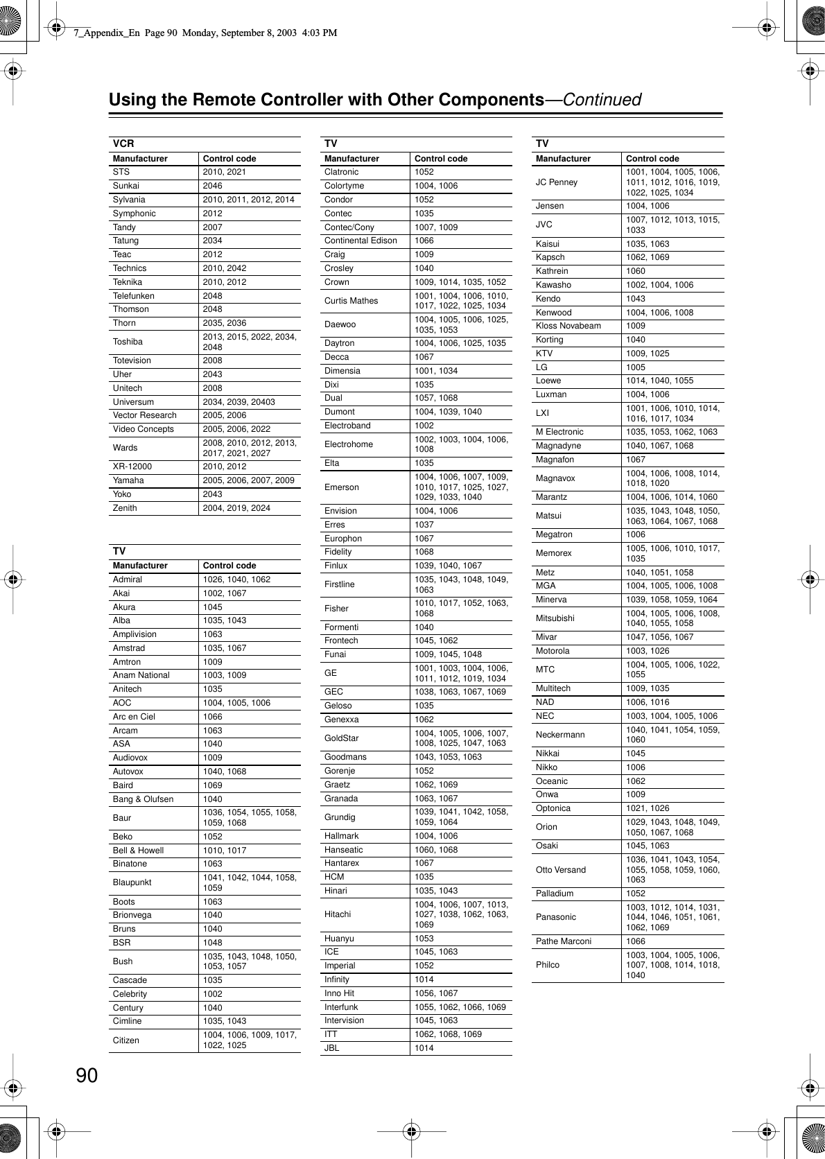
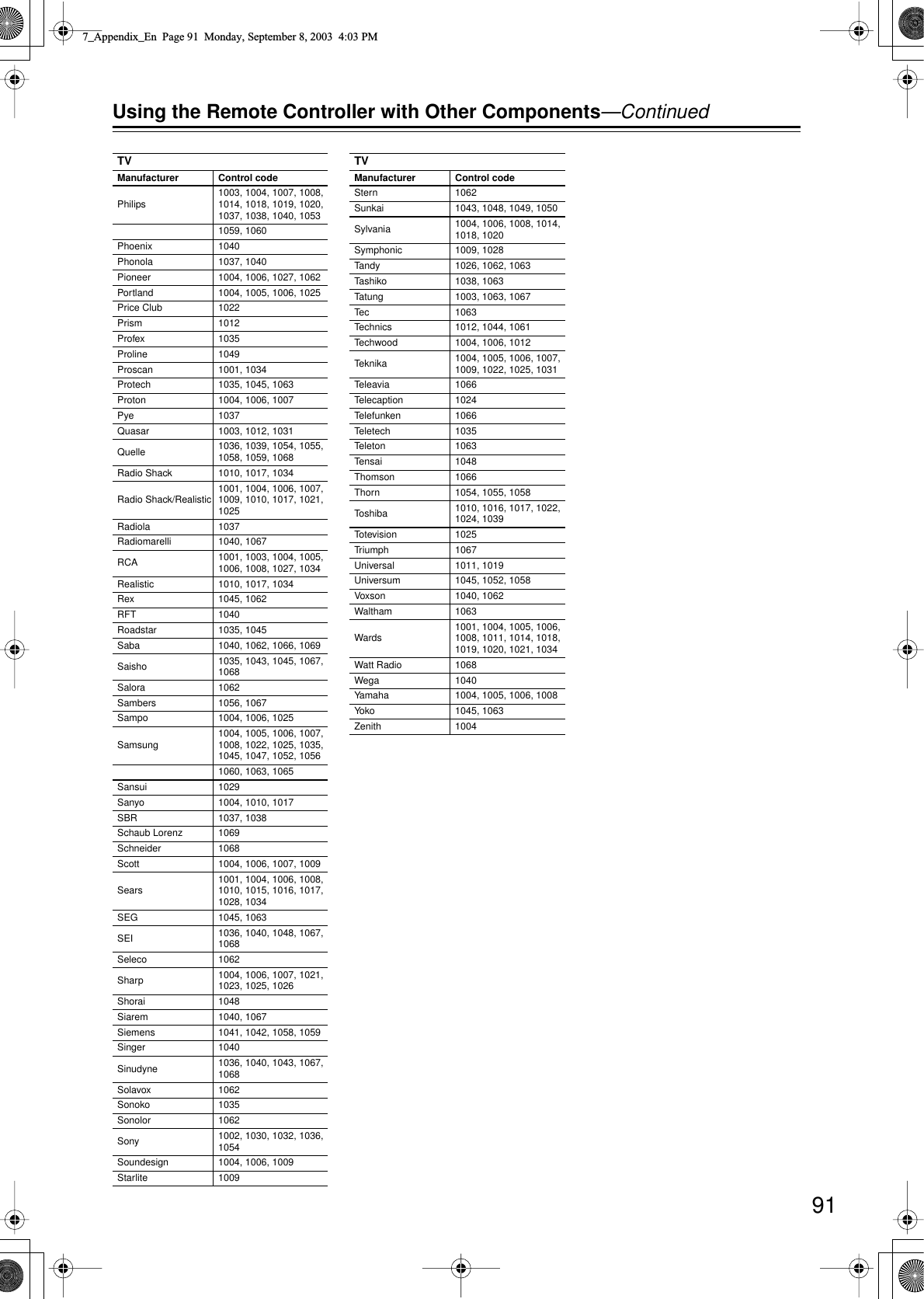
![87 Using the Remote Controller with Other Components You can use the TX-NR901’s remote controller (RC-549M) to control your other AV components, including those made by other manufacturers. To do this you can:• Enter a remote control code for the component that you want to control (e.g., DVD, TV, VCR).•Learn commands directly from the other component’s remote controller (see page 94).•Use the Macro function to learn a sequence of actions (see page 95).•You can also edit the remote controller modes (see page 97). By entering the appropriate remote control code for each of your components, you can control each component by selecting the relevant remote controller mode: DVD, TV, VCR, CBL (cable), or SAT (satellite). Remote Control Codes for an Onkyo DVD player The remote control code that you use with an Onkyo DVD player depends on whether it’s connected via , as follows: 5001: Use this code if you’ve connected an cable and an RCA/phono analog audio cable to your DVD player. This is the default setting, so if you’re using , you don’t need to change it. Point the remote controller at the TX-NR901 to operate the DVD player. 5002: Use this code if your DVD player doesn’t have an socket, or you’re not using . Point the remote controller at the DVD player to operate it. Entering a Remote Control Code 1 Look up the appropriate remote control code for the component. See “Remote Control Codes” on page 88 2 Press and hold down the [CUS-TOM] button for more than three seconds. The remote controller enters Custom mode. 3 Roll the scroll wheel to select PRGRM, and then press the scroll wheel. 4 Roll the scroll wheel to select the the remote controller mode you want to use with the component, and then press the scroll wheel. The following remote controller modes can be selected: DVD, TV, VCR, CBL, or SAT. 5 Use the number buttons to enter the 4-digit remote control code. If the code is accepted, the following appears on the display for awhile, and then the normal display reappears.If the code is not accepted, after the message “RETRY” has been displayed, the code entry display reappears, and you should try entering the code again.To cancel this procedure at any point, press the [CUSTOM] button. 6 Select the remote controller mode, point the remote control-ler at the component, and check its operation. The remote controller buttons that can be used in DVD mode are shown on page 17. Those that can be used with the TV, VCR, CBL, and SAT modes are listed on pages 92 and 93. 7_Appendix_En Page 87 Monday, September 8, 2003 4:03 PM](https://usermanual.wiki/Philips-Electronics-Singapore/RC140A/User-Guide-375129-Page-21.png)
![92 Using the Remote Controller with Other Components —Continued Controlling a Satellite Receiver 1. Press the [MODE] button, and then roll the scroll wheel to select SAT.2. Point the remote controller at your satellite receiver, and use the following buttons (you must enter appropriate remote control code first). The following buttons control the TX-NR901. Controlling a VCR 1. Press the [MODE] button, and then roll the scroll wheel to select VCR.2. Point the remote controller at your VCR, and use the following buttons (you must enter appropriate remote control code first). The following buttons control the TX-NR901. [ON], [STANDBY] Set the satellite receiver to On or Standby [MENU] Display menu [CH/DISC] Select satellite channels [ ]/[ ]/[ ]/[ ] Select menu items [ENTER] Confirm selection Number buttons Enter numbers [VOL] Adjust the TX-NR901 volume [MUTING] Mute the TX-NR901 [ON], [STANDBY] Set the VCR to On or Standby [CH/DISC] Select TV channels [TV INPUT] Select TV or VCR input [] Play [] Stop [] Rewind [] Fast forward [] Pause Number buttons Enter numbers [VOL] Adjust the TX-NR901 volume [MUTING] Mute the TX-NR901 7_Appendix_En Page 92 Monday, September 8, 2003 4:03 PM](https://usermanual.wiki/Philips-Electronics-Singapore/RC140A/User-Guide-375129-Page-26.png)
![93 Using the Remote Controller with Other Components —Continued Controlling a TV 1. Press the [MODE] button, and then roll the scroll wheel to select TV.2. Point the remote controller at your satellite receiver, and use the following buttons (you must enter appropriate remote control code first). The following buttons control the TX-NR901. Controlling a Cable Receiver 1. Press the [MODE] button, and then roll the scroll wheel to select CBL.2. Point the remote controller at your satellite receiver, and use the following buttons (you must enter appropriate remote control code first). The following buttons control the TX-NR901. TV [ ] TV on/off TV CH [+]/[–] Select TV channels [ENTER] Confirm selection Number buttons Enter numbers TV VOL [ ]/[ ] Adjust the TV volume [VOL] Adjust the TX-NR901 volume [MUTING] Mute the TX-NR901 [ON], [STANDBY] Set the cable receiver to On or Standby [CH/DISC] Select cable channels [ENTER] Confirm selection [TV INPUT] Select TV or VCR input Number buttons Enter numbers [VOL] Adjust the TX-NR901 volume [MUTING] Mute the TX-NR901 7_Appendix_En Page 93 Monday, September 8, 2003 4:03 PM](https://usermanual.wiki/Philips-Electronics-Singapore/RC140A/User-Guide-375129-Page-27.png)
![94 Using the Remote Controller with Other Components —Continued You can teach the TX-NR901’s remote controller new commands simply by transmitting commands from another remote controller one at time. For example, by transmitting the Play and Stop commands from your CD player’s remote controller, the TX-NR901’s remote con-troller can be taught to transmit those commands when its Play [ ] and Stop [ ] buttons are pressed in CD mode. Note: • The following buttons cannot be taught new com-mands: [LIGHT], [CUSTOM], [MACRO], [MODE], [INPUT], [ZONE 2], and the scroll wheel button. Learning Commands from Another Remote Controller 1 Press and hold the [CUSTOM] button for more than three sec-onds. The remote controller enters Custom mode. 2 Roll the scroll wheel to select LEARN, and then press the scroll wheel. 3 Roll the scroll wheel to select the the remote controller mode you want to teach a new command, and then press the scroll wheel. The following remote controller modes can be selected: DVD, TV, VCR, CBL, or SAT. 4 On the TX-NR901’s remote con-troller, press the button you want to teach the new command. If you press a button that cannot be taught a new command, the message “RETRY” appears and you should press another button. 5 Point the remote controllers at each other, about 2 to 6 inches (5–15 cm) apart, and then, on the other remote controller, press the button whose command you want to learn. When the command has been learnt successfully, “OK” appears on the dis-play. You may need to press the button several times.If the command is not learnt success-fully, after the message “FAIL” has been displayed, the mode select display reappears (step 3), and you should try again. 6 To teach the TX-NR901’s remote controller more new commands, repeat steps 3 through 5. Press the [CUSTOM] button when you’ve finished. 7_Appendix_En Page 94 Monday, September 8, 2003 4:03 PM](https://usermanual.wiki/Philips-Electronics-Singapore/RC140A/User-Guide-375129-Page-28.png)
![95 Using the Remote Controller with Other Components —Continued With the Macro function you can program the remote controller to perform a sequence of actions with one press of a button. For example, normally you need to per-form the following actions to use a CD player that’s con-nected to the TX-NR901:1. Press the scroll wheel, (to select AMP mode).2. Press the [ON] button (to turn on the TX-NR901).3. Roll the scroll wheel to select CD (to select the CD remote controller mode and the CD input source).4. Press the Play [ ] button (to start the CD player).With the Macro function you can program the remote controller to do all of this with one press of a button. Making Macros You can make up to eight macros, and each macro can perform up to eight actions. Running Macros Programmed macros can be run as follows. Using Macros 1 Press and hold the [CUSTOM] button for more than three sec-onds. The remote controller enters Custom mode. 2 Roll the scroll wheel to select MACRO, and then press the scroll wheel. 3 Roll the scroll wheel to select EDIT, and then press the scroll wheel. 4 Roll the scroll wheel to select a macro, and then press the scroll wheel. Macros are numbered from 1 to 8.Macro #1 selectedAction #1 5 On the remote controller, press the buttons whose actions you want to program into the macro in the order you want them per-formed. To program the CD example in the left column into a macro: press the scroll wheel, press the [ON] button, roll the scroll wheel to select CD, press the scroll wheel, and then press the Play [] button.Actions are numbered from 1 to 8.After each button is pressed, “SET” fol-lowed by “KEY” is displayed.To add an action that selects an input source for the main room or Zone 2, press the [INPUT] button or [ZONE 2] button, respectively, roll the scroll wheel to select the input source, and then press the scroll wheel. 6 When you’ve finished, press the [MACRO] button. After the following appears on the dis-play, the display returns to normal. 1 Press the [MACRO] button. 2 Press the number button corre-sponding to the macro’s number. The actions in the macro are performed in the order in which they were pro-grammed.Macro #1 selected8 actions learnt7_Appendix_En Page 95 Monday, September 8, 2003 4:03 PM](https://usermanual.wiki/Philips-Electronics-Singapore/RC140A/User-Guide-375129-Page-29.png)
![96Using the Remote Controller with Other Components—ContinuedNaming MacrosYou can name your macros as follows. Names may con-tain of up to five characters.1Press and hold the [CUSTOM] button for more than three sec-onds.The remote controller enters Custom mode.2Roll the scroll wheel to select MACRO, and then press the scroll wheel.3Roll the scroll wheel to select NAME, and then press the scroll wheel.4Roll the scroll wheel to select the number of the macro that you want to name, and then press the scroll wheel.5Roll the scroll wheel to select a character, and then press the scroll wheel to set it.The following characters are available.1st characterMacro #1 selected0 1 2 3 4 5 6 7 8 9 A B C D E F G H I J K L M N O P Q R S T U V W X Y Z + – = < > _ / space_1st character set6Repeat step 5 until you’ve entered all 5 characters.The previous menu reappears.If the name you are entering consists of less than five characters, enter spaces at the end to make it up to five.7_Appendix_En Page 96 Monday, September 8, 2003 4:03 PM](https://usermanual.wiki/Philips-Electronics-Singapore/RC140A/User-Guide-375129-Page-30.png)
![97Using the Remote Controller with Other Components—ContinuedAdding New Remote Controller ModesYou can add additional modes (DVD, TV, VCR, CBL, SAT) to the remote controller. This is useful if, for exam-ple, you have several DVD players or TVs.Reordering the Remote Controller ModesYou can change the order in which the remote controller modes appears when you roll the scroll wheel. The posi-tion of the AMP mode cannot be changed.Editing Remote Controller Modes1Press and hold the [CUSTOM] button for more than three sec-onds.The remote controller enters Custom mode.2Roll the scroll wheel to select MODE, and then press the scroll wheel.3Roll the scroll wheel to select ADD, and then press the scroll wheel.4Roll the scroll wheel to select the type of mode you want to add, and then press the scroll wheel.You can add up to 5 additional DVD modes, 3 TV modes, 2 VCR modes, and 2 CBL modes.1Press and hold the [CUSTOM] button for more than three sec-onds.The remote controller enters Custom mode.2Roll the scroll wheel to select MODE, and then press the scroll wheel.3Roll the scroll wheel to select SORT, and then press the scroll wheel.4Roll the scroll wheel to select the mode you want to move, and then press the scroll wheel.5Roll the scroll wheel to select the mode before which you want to insert the specified mode, and then press the scroll wheel.Here the specified mode will be inserted before the “VCR” mode.If the move is successful, after “OK” has been displayed, the SORT display (step 3) reappears.7_Appendix_En Page 97 Monday, September 8, 2003 4:03 PM](https://usermanual.wiki/Philips-Electronics-Singapore/RC140A/User-Guide-375129-Page-31.png)
![98Using the Remote Controller with Other Components—ContinuedDeleting Remote Controller ModesYou can delete remote controller modes that you don’t need, such as modes for components that you don’t have. The AMP mode cannot be deleted.Assigning Remote Controller ModesWith this function you can assign a remote controller mode to an input source. This is useful when you con-nect, say, a CD recorder to the TAPE IN/OUT sockets. In this case it’s convenient to assign the remote controller’s CD mode to the TAPE input source.1Press and hold the [CUSTOM] button for more than three sec-onds.The remote controller enters Custom mode.2Roll the scroll wheel to select MODE, and then press the scroll wheel.3Roll the scroll wheel to select DEL, and then press the scroll wheel.4Roll the scroll wheel to select the mode you want to delete, and then press the scroll wheel.If the mode is deleted successfully, after “OK” has been displayed, the DEL display (step 3) reappears.1Press and hold the [CUSTOM] button for more than three sec-onds.The remote controller enters Custom mode.2Roll the scroll wheel to select MODE, and then press the scroll wheel.3Roll the scroll wheel to select ASSIGN, and then press the scroll wheel.4Roll the scroll wheel to select the mode you want to assign, and then press the scroll wheel.5Roll the scroll wheel to select the input source you want to assign to the specified mode, and then press the scroll wheel.If the assignment is successful, after “OK” has been displayed, the ASSIGN display (step 3) reappears.7_Appendix_En Page 98 Monday, September 8, 2003 4:03 PM](https://usermanual.wiki/Philips-Electronics-Singapore/RC140A/User-Guide-375129-Page-32.png)
![99Using the Remote Controller with Other Components—ContinuedYou can reset the remote controller to its default settings.Resetting the Remote Controller1Press and hold the [CUSTOM] button for more than three sec-onds.The remote controller enters Custom mode.2Roll the scroll wheel to select MODE, and then press the scroll wheel.3Roll the scroll wheel to select RESET, and then press the scroll wheel.4Roll the scroll wheel to select YES, and then press the scroll wheel.The remote controller is reset to its default settings.7_Appendix_En Page 99 Monday, September 8, 2003 4:03 PM](https://usermanual.wiki/Philips-Electronics-Singapore/RC140A/User-Guide-375129-Page-33.png)