Philips Electronics Singapore RC140A RF Remote control User Manual Onkyo TX NR901 Instruction Manual
Philips Electronics Singapore Pte Ltd RF Remote control Onkyo TX NR901 Instruction Manual
Users manual

En
AV Receiver
TX-NR901
Instruction Manual
Thank you for purchasing the Onkyo AV Receiver.
Please read this manual thoroughly before making
connections and plugging in the unit.
Following the instructions in this manual will enable
you to obtain optimum performance and listening
enjoyment from your new AV Receiver.
Please retain this manual for future reference.
Contents
TX-NR901_En.book Page 1 Friday, August 15, 2003 7:48 PM
2
Important Safety Instructions
1. Read these instructions.
2. Keep these instructions.
3. Heed all warnings.
4. Follow all instructions.
5. Do not use this apparatus near water.
6. Clean only with dry cloth.
7. Do not block any ventilation openings. Install in
accordance with the manufacturer’s instructions.
8. Do not install near any heat sources such as radia-
tors, heat registers, stoves, or other apparatus
(including amplifiers) that produce heat.
9. Do not defeat the safety purpose of the polarized or
grounding-type plug. A polarized plug has two
blades with one wider than the other. A grounding
type plug has two blades and a third grounding
prong. The wide blade or the third prong are pro-
vided for your safety. If the provided plug does not
fit into your outlet, consult an electrician for
replacement of the obsolete outlet.
10. Protect the power cord from being walked on or
pinched particularly at plugs, convenience recepta-
cles, and the point where they exit from the appara-
tus.
11. Only use attachments/accessories specified by the
manufacturer.
12.
Use only with the cart, stand,
tripod, bracket, or table spec-
ified by the manufacturer, or
sold with the apparatus.
When a cart is used, use cau-
tion when moving the cart/
apparatus combination to
avoid injury from tip-over.
13. Unplug this apparatus during lightning storms or
when unused for long periods of time.
14. Refer all servicing to qualified service personnel.
Servicing is required when the apparatus has been
damaged in any way, such as power-supply cord or
plug is damaged, liquid has been spilled or objects
have fallen into the apparatus, the apparatus has
been exposed to rain or moisture, does not operate
normally, or has been dropped.
15. Damage Requiring Service
Unplug the apparatus from the wall outlet and refer
servicing to qualified service personnel under the
following conditions:
A. When the power-supply cord or plug is damaged,
B. If liquid has been spilled, or objects have fallen
into the apparatus,
C. If the apparatus has been exposed to rain or
water,
D. If the apparatus does not operate normally by
following the operating instructions. Adjust only
those controls that are covered by the operating
instructions as an improper adjustment of other
controls may result in damage and will often
require extensive work by a qualified technician
to restore the apparatus to its normal operation,
E. If the apparatus has been dropped or damaged in
any way, and
F. When the apparatus exhibits a distinct change in
performance this indicates a need for service.
16. Object and Liquid Entry
Never push objects of any kind into the apparatus
through openings as they may touch dangerous volt-
age points or short-out parts that could result in a
fire or electric shock.
The apparatus shall not be exposed to dripping or
splashing and no objects filled with liquids, such as
vases shall be placed on the apparatus.
Don’t put candles or other burning objects on top of
this unit.
17. Batteries
Always consider the environmental issues and fol-
low local regulations when disposing of batteries.
18. If you install the apparatus in a built-in installation,
such as a bookcase or rack, ensure that there is ade-
quate ventilation.
Leave 20 cm (8") of free space at the top and sides
and 10 cm (4") at the rear. The rear edge of the shelf
or board above the apparatus shall be set 10 cm (4")
away from the rear panel or wall, creating a flue-like
gap for warm air to escape.
WARNING:
TO REDUCE THE RISK OF FIRE OR ELECTRIC
SHOCK, DO NOT EXPOSE THIS APPARATUS
TO RAIN OR MOISTURE.
CAUTION:
TO REDUCE THE RISK OF ELECTRIC SHOCK,
DO NOT REMOVE COVER (OR BACK). NO
USER-SERVICEABLE PARTS INSIDE. REFER
SERVICING TO QUALIFIED SERVICE
PERSONNEL.
The lightning flash with arrowhead symbol, within an
equilateral triangle, is intended to alert the user to the
presence of uninsulated “dangerous voltage” within
the product’s enclosure that may be of sufficient
magnitude to constitute a risk of electric shock to
persons.
The exclamation point within an equilateral triangle is
intended to alert the user to the presence of important
operating and maintenance (servicing) instructions in
the literature accompanying the appliance.
WARNING
RISK OF ELECTRIC SHOCK
DO NOT OPEN RISQUE DE CHOC ELECTRIQUE
NE PAS
OUVRIR
AVIS
PORTABLE CART WARNING
S3125A
TX-NR901_En.book Page 2 Friday, August 15, 2003 7:48 PM

3
Precautions
For U.S. Models
Note to CATV system installer:
This reminder is provided to call the CATV system
installer’s attention to Section 820-40 of the NEC which
provides guidelines for proper grounding and, in partic-
ular, specifies that the cable ground shall be connected
to the grounding system of the building, as close to the
point of cable entry as practical.
FCC Information for User
CAUTION:
The user changes or modifications not expressly
approved by the party responsible for compliance could
void the user’s authority to operate the equipment.
NOTE:
This equipment has been tested and found to comply
with the limits for a Class B digital device, pursuant to
Part 15 of the FCC Rules.
These limits are designed to provide reasonable protec-
tion against harmful interference in a residential instal-
lation. This equipment generates, uses and can radiate
radio frequency energy and, if not installed and used in
accordance with the instructions, may cause harmful
interference to radio communications. However, there is
no guarantee that interference will not occur in a partic-
ular installation.
If this equipment does cause harmful interference to
radio or television reception, which can be determined
by turning the equipment off and on, the user is encour-
aged to try to correct the interference by one or more of
the following measures:
• Reorient or relocate the receiving antenna.
• Increase the separation between the equipment and receiver.
•Connect the equipment into an outlet on a circuit different from
• that to which the receiver is connected.
• Consult the dealer or an experienced radio/TV technician
for help.
For Canadian model
NOTE:
This class B digital apparatus complies with
Canadian ICES-003.
For models having a power cord with a polarized plug:
CAUTION:
TO PREVENT ELECTRIC SHOCK,
MATCH WIDE BLADE OF PLUG TO WIDE SLOT,
FULLY INSERT.
Modèle pour les Canadien
REMARQUE:
Cet appareil numérique de la classe B
est conforme à la norme NMB-003 du Canada.
Sur les modèles dont la fiche est polarisee:
ATTENTION:
POUR ÉVITER LES CHOCS ÉLEC-
TRIQUES, INTRODUIRE LA LAME LA PLUS
LARGE DE LA FICHE DANS LA BORNE CORRE-
SPONDANTE DE LA PRISE ET POUSSER
JUSQU’AU FOND.
1. Recording Copyright
—Unless it’s for personal use
only, recording copyrighted material is illegal with-
out permission of the copyright holder.
2. AC Fuse
— The AC fuse inside the TX-NR901 is
not user-serviceable. If you cannot turn on the
TX-NR901, contact your Onkyo dealer.
3. Care
—Occasionally you should dust the
TX-NR901 all over with a soft cloth. For stubborn
stains, use a soft cloth dampened with a weak solu-
tion of mild detergent and water. Dry the
TX-NR901 immediately afterwards with a clean
cloth. Don’t use abrasive cloths, thinners, alcohol,
or other chemical solvents, because they may dam-
age the finish or remove the panel lettering.
4. Power
WARNING
BEFORE PLUGGING IN THE UNIT FOR THE
FIRST TIME, READ THE FOLLOWING SECTION
CAREFULLY.
AC outlet voltages vary from country to country. Make
sure that the voltage in your area meets the voltage
requirements printed on the TX-NR901’s rear panel
(e.g., AC 230 V, 50 Hz or AC 120 V, 60 Hz).
The Worldwide model has a voltage selector for com-
patibility with power systems around the world. Before
you plug in this model, make sure that the voltage selec-
tor is set to the correct voltage for your area.
For North American model
Setting the [STANDBY/ON] switch to STANDBY does
not fully shutdown the TX-NR901. If you do not intend
to use the TX-NR901 for an extended period, remove
the power cord from the AC outlet.
TX-NR901_En.book Page 3 Friday, August 15, 2003 7:48 PM
4
Precautions .................................................................................................................. 3
Features........................................................................................................................6
Supplied Accessories ................................................................................................. 7
Before Using the TX-NR901........................................................................................ 8
Setting the Voltage Selector (Worldwide model only)..................................................................8
Installing the Batteries..................................................................................................................8
Using the Remote Controller........................................................................................................8
Front & Rear Panels .................................................................................................... 9
Front Panel...................................................................................................................................9
Display .......................................................................................................................................11
Rear Panel .................................................................................................................................12
Remote Controller ..................................................................................................... 14
Amp Mode..................................................................................................................................14
Net-Tune Mode ..........................................................................................................................15
DVD Mode..................................................................................................................................16
CD Mode....................................................................................................................................18
MiniDisc Mode............................................................................................................................19
Tape Mode.................................................................................................................................20
About Home Theater ................................................................................................. 21
Enjoying Home Theater .............................................................................................................21
Connecting the TX-NR901......................................................................................... 22
Before Making Any Connections................................................................................................22
AV Cables & Connectors ...........................................................................................................22
Connecting speakers .................................................................................................................23
Connecting Antenna...................................................................................................................25
Connecting Your TV or Projector ...............................................................................................27
Connecting the video component...............................................................................................28
Connecting a TV, Satellite/Cable Tuner, LD player, etc.............................................................31
Connecting a Camcorder, Games Console, etc.........................................................................32
Connecting auxiliary power amplifier .........................................................................................34
Connecting to an external device with 12 V TRIGGER terminal................................................34
Connections for remote control ()...............................................................................................35
Connecting the power cords from other devices........................................................................35
RS 232 port................................................................................................................................35
Connecting the power cord ........................................................................................................36
Turning on the power .................................................................................................................36
Turning on the power from the remote controller.......................................................................36
Basic Setup ................................................................................................................ 37
OSD Map ...................................................................................................................................37
Speaker Setup ...........................................................................................................................38
Input Setup.................................................................................................................................42
Remote Setup ............................................................................................................................45
AM Frequency Step ...................................................................................................................46
TV Format (For all models other than North American and Australian models) ........................47
To change the display of the input source from TAPE to MD ....................................................47
Basic Playback Functions ........................................................................................ 48
Displaying Information................................................................................................................58
Adjusting the Speaker Balance Temporarily..............................................................................59
Using Re-EQ function ................................................................................................................59
TX-NR901_En.book Page 4 Friday, August 15, 2003 7:48 PM
5
Using the Late Night function (only for the Dolby Digital)...........................................................59
Advanced Playback Functions................................................................................. 60
Using the Multi-Channel Inputs..................................................................................................61
Recording...................................................................................................................................62
Advanced Setup ........................................................................................................ 64
Configuring the listening modes frequently you use (Listening Mode Preset) ...........................64
Audio adjust ...............................................................................................................................65
Preference..................................................................................................................................70
Other settings.............................................................................................................................72
Using Net-Tune.......................................................................................................... 74
Connecting the TX-NR901 to your Ethernet Network ................................................................75
Enjoying Internet radio ...............................................................................................................76
Playing a music file saved on your PC.......................................................................................78
Music Server Setup....................................................................................................................80
Network Setup............................................................................................................................80
Using Zone 2.............................................................................................................. 82
Connect the Speaker for ZONE 2 (Another Room)....................................................................82
Operating components not reached by the remote controller signals (IR IN/OUT)....................83
Setting the ZONE 2....................................................................................................................84
Enjoy the Movie/Music in Another Room ...................................................................................85
Using the Remote Controller with Other AV Components.................................... 87
TX-NR901_En.book Page 5 Friday, August 15, 2003 7:48 PM
6
Features
Amp
• 7-channel amplifier
• 110 watts per channel into 8 ohms, 20 Hz to 20 kHz,
less than 0.08% total harmonic distortion (FTC rating)
• WRAT (Wide Range Amplifier Technology)
• Optimum Gain Volume Circuitry
• 192 kHz/24-bit D/A converters (not surround back
channels)
• Multiroom (zone 2) capability, with independent
source selection and volume control
Audio/Video
• THX Surround EX
1
• THX Select certified
• Dolby
Digital, Dolby Digital EX, Dolby Pro Logic II
2
•DTS, DTS-ES Discrete 6.1, DTS-ES Matrix 6.1, DTS
Neo:6, and DTS 96/24
3
• Theater-Dimensional virtual surround mode
4
• Non-Scaling configuration
• Advanced 24-bit DSP chip (5 DSP soundfields)
• 96 kHz/24-bit D/A converters on all channels
•2 component video inputs, 1 output
• Composite video to S-Video and S-Video to compos-
ite video conversion
• Composite and S-Video to component video conver-
sion
•6 S-Video inputs, 3 outputs
•7 assignable digital inputs (4 optical, 3 coaxial),
2 digital outputs, 1 optical digital input for video 5
input
•Pre outs for front L/R, center, surround L/R, surround
back L/R (or Zone 2 L/R), and Subwoofer
FM/AM Tuner
• 40 FM/AM presets
• FM auto tuning
Others
• Easy-to-use onscreen setup menus (OSD)
• Remote controller has scroll wheel and LCD display
for quick and easy operation
•VLSC (Vector Linear Shaping Circuitry) for left, cen-
ter, and right channels (not North American and Aus-
tralian models)
• IntelliVolume
• Character input for naming radio presets and input
sources
•Net-Tune for Internet radio and MP3, WAV, and WMA
playback
• Ethernet port for use with Net-Tune
1. THX is a trademark or registered trademark of THX Ltd.
2. Manufactured under license from Dolby Laboratories. “Dolby,” “Pro Logic,” “Surround EX,” and the double-D symbol are trademarks of
Dolby Laboratories.
3. “DTS,” “DTS 96/24,” “DTS-ES,” and “Neo:6” are trademarks of Digital Theater Systems, Inc.
4. “Theater-Dimensional” and “Net-Tune” are trademarks of Onkyo Corporation.
Re-Equalization and the “Re-EQ” logo are trademarks of THX Ltd.
Windows Media, and the Windows logo are trademarks, or registered trademarks of Microsoft Corporation in the United
States and/or other countries.
Intel and Pentium are registered trademarks of Intel Corporation.
MPEG Layer-3 audio coding technology licensed from Fraunhofer IIS and Thomson Multimedia.
“Xiva” is a registered trademark of Imerge Limited.
Xantech is a registered trademark of Xantech Corporation.
Niles is a registered trademark oh Niles Audio Corporation.
Ethernet is a registered trademark of Xerox Corporation.
THX Select
Before any home theatre component can be THX Select
certified, it must pass a rigorous series of quality and
performance tests. Only then can a product feature the
THX Select logo, which is your guarantee that the
Home Theatre products you purchase will give you
superb performance for many years to come. THX
Select requirements define hundreds of parameters,
including power amplifier performance, and pre-ampli-
fier performance and operation for both digital and ana-
log domains. THX Select receivers also feature
proprietary THX technologies (e.g., THX Mode) which
accurately translate film soundtracks for home theater
playback.
TX-NR901_En.book Page 6 Friday, August 15, 2003 7:48 PM
7
Supplied Accessories
Make sure you have the following accessories:
* In catalogs and on packaging, the letter added to the
end of the product name indicates the color of the
TX-NR901. Specifications and operation are the same
regardless of color.
AM loop antenna
Remote controller & two batteries (AA/R6)
Indoor FM antenna
(Connector type varies from country to country.)
Speaker cable labels
Power-plug adapter
(Only supplied in certain countries. Use this adapter if
your AC outlet does not match with the plug on the
TX-NR901’s power cord. Adapter type varies from
country to country.)
75/300-ohm antenna adapter
(Not supplied with North American model.)
North American model: RC-
548M
Other models:
RC-549M
Front
Left
Front
Left
SP-B
/
Zone 2
Left
SP-B
/
Zone 2
Left
Surround
Right
Surround
Right
Surround Back
Right
Surround Back
Right
Zone 2
Right
Zone 2
Right
Front
Left
Front
Left
SP-B
/
Zone 2
Left
SP-B
/
Zone 2
Left
Front
Right
Front
Right
SP-B
/
Zone 2
Right
SP-B
/
Zone 2
Right
Front
Right
Front
Right
SP-B
/
Zone 2
Right
SP-B
/
Zone 2
Right
Surround
Right
Surround
Right
Center
Center
Center
Center
Surround
Left
Surround
Left
Surround
Left
Surround
Left
Surround Back
Right
Surround Back
Right
Zone 2
Right
Zone 2
Right
Surround Back
Left
Surround Back
Left
Zone 2
Left
Zone 2
Left
Surround Back
Left
Surround Back
Left
Zone 2
Left
Zone 2
Left
12
3
Speaker Cable
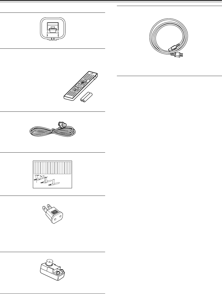
Power cord
(Not supplied with North American and Australian
models, which have an integral power cord.)
TX-NR901_En.book Page 7 Friday, August 15, 2003 7:48 PM
8
Before Using the TX-NR901
The Worldwide model has a voltage selector for compat-
ibility with power systems around the world. Before you
plug in this model, make sure that the voltage selector is
set to the correct voltage for your area. If it isn’t, use a
small screwdriver to set it as appropriate. For example, if
the voltage in your area is 120 volts, set the selector to
“120V.” And if it’s between 220 and 230 volts, set it to
“220-230V.”
Notes:
• The batteries should last for about six months,
although this will vary with usage.
• If the remote controller doesn’t work reliably, try
replacing the batteries.
• Don’t mix new and old batteries or different types of
batteries.
•If you intend not to use the remote controller for a long
time, remove the batteries to prevent damage from
leakage or corrosion.
•Expired batteries should be removed as soon as possi-
ble to prevent damage from leakage or corrosion.
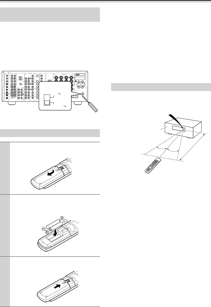
To use the remote controller, point it at the TX-NR901’s
remote control sensor, as shown below.
Notes:
• The remote controller may not work reliably if the
TX-NR901 is subjected to bright light, such as direct
sunlight or inverter-type fluorescent lights. Keep this
in mind when installing.
•If another remote controller of the same type is used in
the same room, or the TX-NR901 is installed close to
equipment that uses infrared rays, the remote control-
ler may not work reliably.
•Don’t put anything, such as a book, on the remote con-
troller, because the buttons may be pressed inadvert-
ently, thereby draining the batteries.
• The remote controller may not work reliably if the
TX-NR901 is installed in a rack behind colored glass
doors. Keep this in mind when installing.
•The remote controller will not work if there’s an obsta-
cle between it and the TX-NR901’s remote control
sensor.
Setting the Voltage Selector
(Worldwide model only)
Installing the Batteries
1
To open the battery compartment, press
the small hollow and slide off the cover.
2
Insert the two supplied batteries (AA/R6)
in accordance with the polarity diagram
inside the battery compartment.
3
Put the cover onto the remote controller
and slide it shut.
FM
75
OUT
OUT
OUT
OUT
L
OUT
PHONO
DIGITAL
IN
PRE OUT
DIGITAL
OUT
OPT
OPT
2
1
2
3
4
1
2
FRONT
SUB
SURR
RL
AUDIO
RL
CD
TAPE
RL
AUDIO VIDEO S VIDEO
MONITOR
OUT
RL
IN
IN
IN
IN
IN
IN
IN
ZONE 2
DVD
VIDEO 1
VIDEO 2
VIDEO 3
VIDEO 4
AUDIO AUDIO VIDEO S VIDEO
1
3
GND
SURR
BACK/
ZONE 2
RL
IN
AC
INLET
COAX
R
ZONE 2
REMOTE
CONTROL
RS232
I
R
12V TRIGGER OUT
IN
CENTER
ETHERNET
(Net -Tune)
RL
MULTI CH
INPUT
FRONT
SUB
SURR
SURR
BACK
CENTER
RL
AM
ANTENNA
COMPONENT
VIDEO
Y
PB
PR
OUTPUT
INPUT 1
Y
PB
PR
INPUT 2
Y
PB
PR
VOLTAGE
SELECTOR
220-230V
120V
TX-NR
901
MODEL NO.
/
SURR
BACK/
ZONE 2
SPEAKERS
FRONT SPEAKERS L
RL R
SURR SPEAKERS
CENTER
SPEAKER
RL
VOLTAGE
SELECTOR
220-230V
120V
Using the Remote Controller
30˚ 30˚
TX-NR901
Approx. 16 ft.
(5 m)
Remote control sensor
Standby indicator
TX-NR901_En.book Page 8 Friday, August 15, 2003 7:48 PM
9
Front & Rear Panels
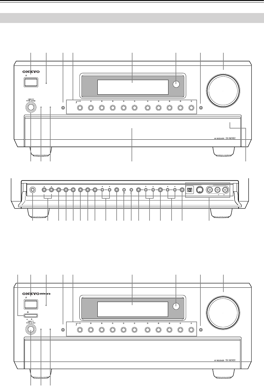
Front Panel
STANDBY/ON
STANDBY
MASTER VOLUME
TUNER PHONO NET AUDIOC
D
TAPE
DVD VIDEO
3
VIDEO
5
VIDEO
4
VIDEO
2
VIDEO
1
VCR
2
VCR
1
ZONE
2
()
GRN
REC ()
RED
AUDIO
SELECTOR DISPL
AY
PURE AUDIO UPSAMPLING
OFF
ON
POWER
PUSH TO OPEN
PHONES
ZONE
2
LEVEL
STEREO SURROUND
THX DSPREC OUT ZONE
2
OFF DIMMER
MEMORY FM MODE
SETUP ENTER
RETURN
S VIDEO VIDEO
DIGITAL
VIDEO
5
INPUT
STANDBY/ON
STANDBY
MASTER VOLUME
TUNER PHONO NET AUDIOC
D
TAPE
DVD VIDEO
3
VIDEO
5
VIDEO
4
VIDEO
2
VIDEO
1
VCR
2
VCR
1
ZONE
2
()
GRN
REC ()
RED
AUDIO
SELECTOR DISPL
AY
PURE AUDIO UPSAMPLING
PUSH TO OPEN
PRESET
TUNINGCLEAR AUDIO
LR
B C D E F G H I
LK
UVWXYZabcTSRQPO d
J
MN
A
B C D E F G H I
LKJ
North American Model
Other Models
Front flap Push here to open the flap
TX-NR901_En.book Page 9 Friday, August 15, 2003 7:48 PM

10
Front & Rear Panels
—Continued
For detailed information, refer to the pages in parenthe-
sis.
A
POWER switch (xx)
North American and Australian models don’t have
this switch.
This is the main power switch. When set to OFF, the
TX-NR901 is completely shutdown. When set to
ON, the TX-NR901 is in Standby mode and the
STANDBY indicator lights up.
Don’t turn on the power until you’ve completed, and
double checked all connections.
Note:
Turning on the TX-NR901 may cause a momentary
power surge that might interfere with other electrical
equipment on the same circuit. If this is a problem,
plug the TX-NR901 into a different branch circuit.
B
STANDBY/ON button (xx)
This button is used to set the TX-NR901 to On or
Standby. For models with a POWER switch, this but-
ton has no effect unless the POWER switch is set to
ON.
C
STANDBY indicator (xx)
This indicator lights up when the TX-NR901 is in
Standby mode, and it flashes while a signal is being
received from the remote controller.
D
AUDIO SELECTOR button (xx)
This button is used to select the audio input signal
format: analog, digital, or multi-channel.
E
Input selector buttons & indicators (xx)
These buttons are used to select the following input
sources: DVD, VIDEO 1–5, TAPE, TUNER,
PHONO, CD, and NET AUDIO. The indicators
show the currently selected input source.
The indicators also show which input source is
selected for zone 2 (sub-room), in which case they
light up green, or which input source is selected for
recording (REC OUT), in which case they light up
red.
F
Display
See “Display” on page 11.
G
Remote-control sensor (xx)
This sensor receives control signals from the remote
controller.
H
DISPLAY button (xx)
This button is used to display various information
about the currently selected input source.
I
MASTER VOLUME control (xx)
This control is used to set the volume of the
TX-NR901 from 0 to 100.
J
DIRECT/PURE AUDIO button (xx)
This button is used to select the Direct and Pure
Audio listening modes.
K
PURE AUDIO indicator (xx)
This indicator lights up when the Pure Audio listen-
ing mode is selected.
L
UPSAMPLING indicator (66)
This indicator lights up when the Upsampling func-
tion is on.
M
PHONES jack (xx)
This 1/4-inch phone jack is for connecting a standard
pair of stereo headphones for private listening.
N
ZONE 2 LEVEL [ ] [ ] buttons (xx)
These buttons are used to set the volume in zone 2
(sub-room).
O
REC OUT button (62)
This button is used to select the input source that you
want to record via the REC OUTs (i.e., TAPE OUT,
VIDEO 1 OUT, VIDEO 2 OUT).
P
ZONE 2 button (85)
This button is used to select the input source that you
want play in zone 2 (sub-room).
QOFF button (62, 85)
This button is used to turn off the REC OUTs (i.e.,
TAPE OUT, VIDEO 1 OUT, VIDEO 2 OUT) or zone
2.
RSTEREO button (52)
This button is used to select the Stereo listening
mode.
SSURROUND button (52)
This button is used to select the Dolby and DTS lis-
tening modes.
TTHX button (52)
This button is used to select the THX listening
modes.
UDSP [ ] [ ] buttons (52)
These buttons are used to select the DSP (digital sig-
nal processor) listening modes.
VDIMMER button (xx)
This button is used to adjust the display brightness.
WMEMORY button (xx)
This button is used when storing and deleting radio
presets.
XFM MODE button (xx)
This button is used to select the FM radio Auto and
Mono modes.
YSETUP button (37, 64)
This button is used to access the onscreen setup
menus (OSD) that appear on the TV that’s connected
to the composite video or S-Video MONITOR OUT.
ZTUNING [ ] [ ] buttons (xx)
These buttons are used to tune into radio stations and
to select items on the onscreen setup menus (OSD).
TX-NR901_En.book Page 10 Friday, August 15, 2003 7:48 PM
11
aENTER button
This button is used when navigating the onscreen
setup menus (OSD), entering names, and confirming
settings.
bPRESET [ ] [ ] buttons (xx)
These buttons are used to select radio presets and to
select items on the onscreen setup menus (OSD).
cRETURN button (xx)
This button is used to return to the previously dis-
played onscreen setup menu (OSD).
dVIDEO 5 INPUTs (xx)
These optical digital audio, S-Video, composite
video, and analog audio inputs can be used to con-
nect a video camera, games console, and so on.
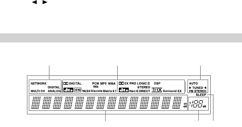
For detailed information, refer to the pages in parenthe-
sis.
1Audio input format indicators
These indicators show the audio input format for the
currently selected input source.
2Listening mode & digital audio format
indicators
These indicators show the currently selected listen-
ing mode and digital audio format.
3Tuning indicators
AUTO indicator:
This indicator lights up when the tuner is tuned to an
FM station and Stereo mode is selected. It goes off
when Mono mode is selected.
TUNED indicator:
This indicator lights up when the tuner is tuned into
an AM or FM station.
FM STEREO indicator:
This indicator lights up when the tuner is tuned to a
stereo FM station. It goes off when Mono mode is
selected.
4Multipurpose display area
Normally, the name of the currently selected input
source is displayed here. When you select the AM or
FM input source, the radio frequency and preset
number are displayed. If you press the [DISPLAY]
button, the currently selected listening mode and
digital audio format are displayed.
5Volume level
The volume level is displayed here.
6SLEEP indicator
This indicator lights up when the Sleep function has
been set.
Display
456
31 2
TX-NR901_En.book Page 11 Friday, August 15, 2003 7:48 PM
12
Front & Rear Panels—Continued
For detailed information, refer to the pages in parenthe-
sis.
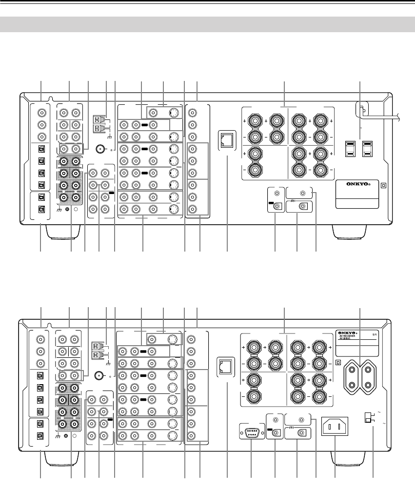
ADIGITAL IN COAX 1–3, OPT 1–4 (xx)
These coaxial and optical digital audio inputs can be
used to connect CD, DVD, or LD (laser disc) players
and other AV components with digital audio outputs.
BDIGITAL OUT OPT 1 & 2 (xx)
These optical digital audio outputs can be used to
connect a CD recorder or other component with dig-
ital inputs.
CPRE OUT—FRONT L/R, SUB, CENTER,
SURR L/R (xx)
If you use the TX-NR901 as a preamp, these analog
audio outputs can be connected to the inputs on a
separate power amp. The SUB output is used to con-
nect a powered subwoofer.
DPRE OUT—SURR BACK/ZONE 2 (xx)
These analog audio outputs can be used to feed the
L/R surround back inputs on a separate power amp
when the TX-NR901 is used as a preamp, or to feed
a power amp in zone 2 (sub-room).
Rear Panel
FM
75
OUT
OUT
OUT
OUT
L
OUT
PHONO
DIGITAL
IN
PRE OUT
DIGITAL
OUT
OPT
OPT
2
1
2
3
4
1
2
FRONT
SUB
SURR
RL
AUDIO
RL
CD
TAPE
RL
AUDIO VIDEO S VIDEO
MONITOR
OUT
RL
IN
IN
IN
IN
IN
IN
IN
ZONE 2
DVD
VIDEO 1
VIDEO 2
VIDEO 3
VIDEO 4
AUDIO AUDIO VIDEO S VIDEO
1
3
GND
SURR
BACK/
ZONE 2
RL
IN
AC
INLET
COAX
R
ZONE 2
REMOTE
CONTROL
RS232
I
R
12V TRIGGER OUT
IN
CENTER
ETHERNET
(Net -Tune)
RL
MULTI CH
INPUT
FRONT
SUB
SURR
SURR
BACK
CENTER
RL
AM
ANTENNA
COMPONENT
VIDEO
Y
PB
PR
OUTPUT
INPUT 1
Y
PB
PR
INPUT 2
Y
PB
PR
VOLTAGE
SELECTOR
220-230V
120V
TX-NR
901
MODEL NO.
/
SURR
BACK/
ZONE 2
SPEAKERS
FRONT SPEAKERS L
RL R
SURR SPEAKERS
CENTER
SPEAKER
RL
FM
75
OUT
OUT
OUT
OUT
L
OUT
PHONO
DIGITAL
IN
PRE OUT
DIGITAL
OUT
OPT
OPT
2
1
2
3
4
1
2
FRONT
SUB
SURR
RL
AUDIO
RL
CD
TAPE
RL
AUDIO VIDEO S VIDEO
MONITOR
OUT
RL
IN
IN
IN
IN
IN
IN
IN
ZONE 2
DVD
VIDEO 1
VIDEO 2
VIDEO 3
VIDEO 4
AUDIO AUDIO VIDEO S VIDEO
1
3
GND
SURR
BACK/
ZONE 2
RL
IN
COAX
R
ZONE 2
REMOTE
CONTROL
I
R
12V TRIGGER OUT
IN
CENTER
ETHERNET
(Net -Tune)
RL
MULTI CH
INPUT
FRONT
SUB
SURR
SURR
BACK
CENTER
RL
AM
ANTENNA
COMPONENT
VIDEO
Y
PB
PR
OUTPUT
INPUT 1
Y
PB
PR
INPUT 2
Y
PB
PR
AC OUTLETS
AC
120
V 60
Hz
SWITCHED
TOTAL 120W 1A MAX.
AV RECEIVER
MODEL NO. TX-NR
901
SURR
BACK/
ZONE 2
SPEAKERS
FRONT SPEAKERS L
RL R
SURR SPEAKERS
CENTER
SPEAKER
RL
TUV
WXY
ZS
RQ
P
ON
B
1CD
E
FG
HIJ
UV
W
ZS
RQ
P
ON
B
1CD
E
FG
HIJ
KL M
KL M
North American Model
Other Models
TX-NR901_En.book Page 12 Friday, August 15, 2003 7:48 PM

13
EMULTI CH INPUT—FRONT L/R, SUB,
CENTER, SURR L/R, SURR BACK L/R (xx)
These analog audio inputs can be used to connect AV
components with multiple analog audio outputs,
including DVD players with individual 7.1 surround
analog audio outputs.
FAM ANTENNA (xx)
These push terminals are for connecting an AM
antenna.
GFM ANTENNA (xx)
This connector is for connecting an FM antenna.
HPHONO IN (xx)
These analog inputs can be used to connect a turnta-
ble with a moving-magnet cartridge.
ICD IN (xx)
These analog inputs can be used to connect a CD
player with analog outputs.
JTAPE IN/OUT (xx)
These analog inputs and outputs can be used to con-
nect a cassette recorder, Mini Disc recorder, or other
recorder with analog inputs and outputs.
KMONITOR OUT (xx)
This S-Video or composite video output can be con-
nected to the video input on your TV or projector.
The onscreen setup menus (OSD) are displayed on
the TV that’s connected here.
LZONE 2 OUT (xx)
These composite video and analog audio outputs can
be used to feed a TV, or a TV and separate power
amp in zone 2 (sub-room).
MDVD IN (xx)
These S-Video, composite video, and analog audio
inputs can be used to connect a DVD player.
NVIDEO 1 & 2 IN/OUT (xx)
These S-Video, composite video, and analog audio
inputs and outputs can be used to connect one or two
video recorders (e.g., VCRs).
OVIDEO 3 & 4 IN (xx)
These S-Video, composite video, and analog audio
inputs can be used to connect one or two video
sources (e.g., cable TV, satellite TV, or a set-top
box).
PCOMPONENT VIDEO OUTPUT (xx)
This component video output can be used to connect
a TV or projector with a component video input.
QCOMPONENT VIDEO INPUT 1 & 2 (xx)
These component video inputs can be used to con-
nect one or two AV components with component
video outputs, such as a DVD player.
RETHERNET (Net-Tune) (74)
This port is for connecting the TX-NR901 to your
Ethernet network for use with Net-Tune (i.e., Inter-
net radio and MP3, WAV, and WMA playback).
SSPEAKERS (xx)
These terminal posts are for connecting your speak-
ers. The SURR BACK/ZONE 2 terminals can be
used with surround back speakers in the main room
or speakers in zone 2 (sub-room).
TRS232 (xx)
This port is for connecting the TX-NR901 to home
automation and external controllers.
North American and Australian models don’t have
this port.
UIR IN/OUT (83)
If you want to use the remote controller to control the
TX-NR901 from zone 2 (sub-room), or if the
TX-NR901 is installed in a cabinet and the line of
sight between the TX-NR901 and the remote con-
troller is obstructed, a commercially available IR
receiver can be connected to the IR IN. A commer-
cially available IR emitter can be connected to the IR
OUT to pass the IR signals along to another AV com-
ponent.
VZONE 2 12V TRIGGER OUT (82)
This output can be connected to the 12-volt trigger
input on a power amp in zone 2 (sub-room). The
power amp can then be turned on or off automati-
cally from the TX-NR901.
W REMOTE CONTROL (xx)
This (Remote Interactive) jack can be connected
to the jack on another Onkyo AV component.
The TX-NR901’s remote controller can then be used
to control that component. To use , you must
make an analog RCA/phono audio connection
between the TX-NR901 and the other AV compo-
nent, even if they are connected digitally.
XAC INLET (xx)
The supplied power cord should be connected here.
North American and Australian models do not have
an AC INLET. They have an integral power cord
instead.
YVOLTAGE SELECTOR (xx)
This voltage selector provides compatibility with
power systems around the world.
North American and Australian models don’t have
this selector.
ZAC OUTLETS (xx)
These switched AC outlets can be used to supply
power to other AV components. The connector type
depends on the country in which you purchased your
TX-NR901.
TX-NR901_En.book Page 13 Friday, August 15, 2003 7:48 PM
14
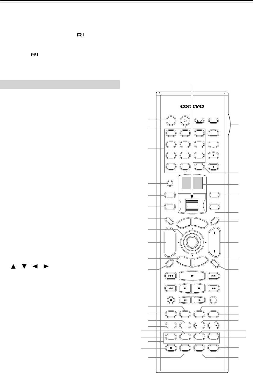
Remote Controller
The TX-NR901’s remote controller is a multipurpose
device that can be used to control not just the TX-NR901
but your other AV components as well. This section
explains how it’s various operating modes can be used to
control the TX-NR901 and various -compatible
Onkyo components. See page 87 for information on
using the remote controller to control Onkyo compo-
nents without and TVs, VCRs, and AV components
made by other manufacturers.
For detailed information, refer to the pages in parenthe-
sis.
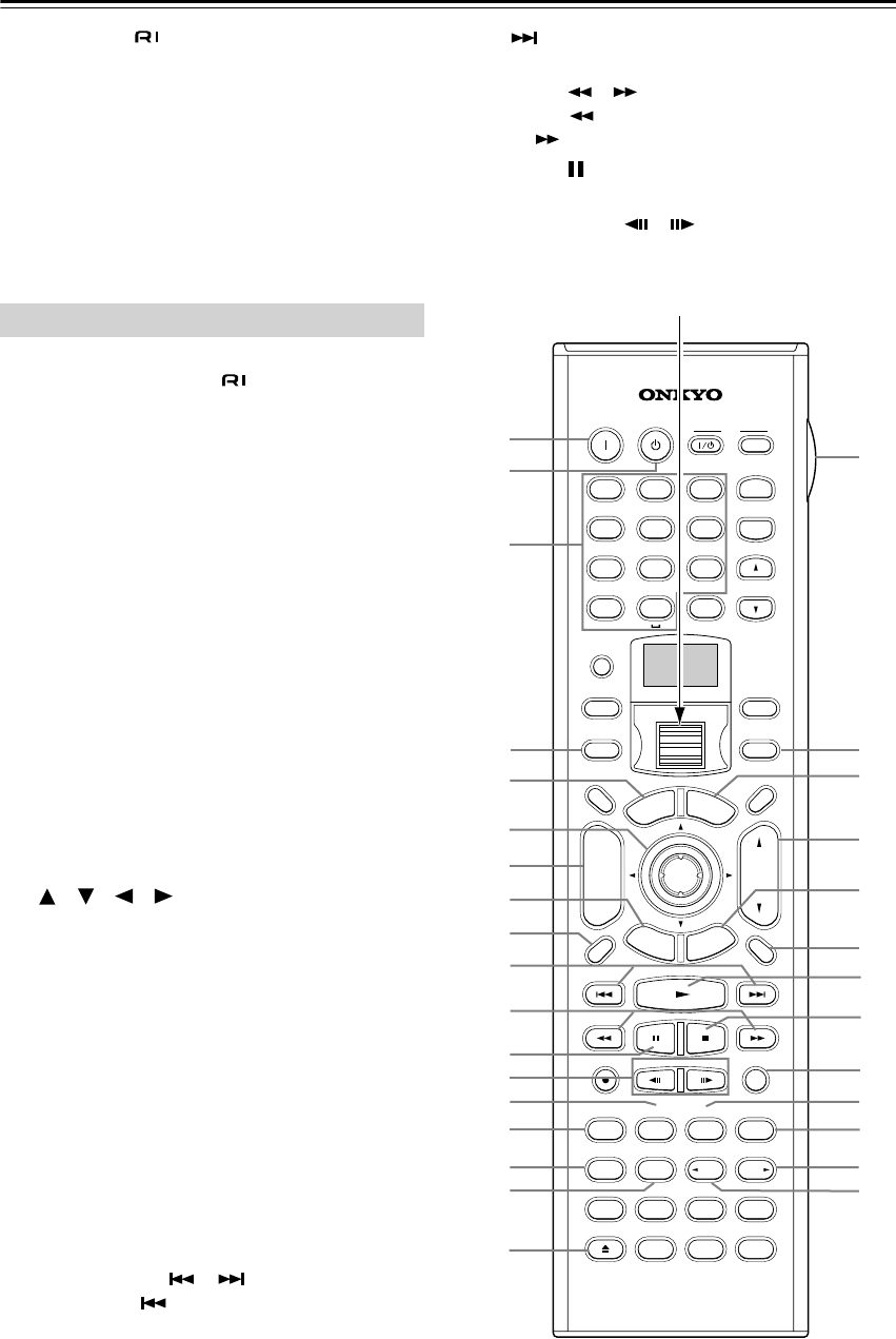
Amp mode is used to control the TX-NR901. To select
Amp mode, press the [MODE] button, and then roll the
scroll wheel until “AMP” appears on the display.
Boxed numbers are for Net-Tune mode (page 15).
AON button
This button is used to turn on the TX-NR901.
BSTANDBY button
This button is used to set the TX-NR901 to Standby.
CNumber/letter buttons
These buttons are used to enter numbers and letters.
DCUSTOM button
This button is used to access various settings that you
can use to customize the operation of the remote
controller.
EMACRO button
This button is used with the Macro function.
FMODE button
This button is used with the scroll wheel to select the
remote controller modes. Press this button first, and
then roll the scroll wheel until “AMP” appears on the
display.
GDIMMER button
This button is used to adjust the display brightness.
H[] [ ] [ ] [ ] & ENTER buttons
These buttons are used to select items on the
onscreen setup menus (OSD). The ENTER button is
also used to enter names and to confirm settings.
ICH/DISC +/– button
This button is used to select radio presets.
JRETURN/EXIT button
This button is used to return to the previously dis-
played onscreen setup menu (OSD).
KDISPLAY button
This button is used to display various information
about the currently selected input source.
LTHX button
This button is used to select the THX listening
modes.
MSURR button
This button is used to select the Dolby and DTS lis-
tening modes.
NDIRECT button
This button is used to select the Direct listening
mode.
OPURE A button
This button is used to select the Pure Audio listening
mode.
Amp Mode
--
/
---
@.
-
'
/ABC DEF
PQRS TUV WXYZ
DIRECT TUNING
GHI JKL MNO
CAPS DELETE
LANGUAGE LOCATION
ALBUM AR
TIST GENRE
PLAYLIST
CUSTOM
DISPLAY
DIMMER
T
V/
VIDEO
SLEEP
RANDOMREC
STEP
/
SLOW
MUTING
ENTER
LAST MANGLE
SUBTITLE
AUDIO
MEMORY
SEARCHA-BREPEAT
ON STANDBY TV
TV CH
TV VOL
RC-549M
A
U
D
I
O
A
D
J
E
X
I
T
G
U
I
D
E
+10 0
CLEAR
123
456
789
INPUT
T
O
P
M
E
N
U
M
E
N
U
S
E
T
U
P
R
E
T
U
R
N
ZONE
2
INPUTMODE
MACRO
VOL
CH
DISC
TEST T
O
NE
CH SEL
PURE A
SURR
DIRECT
STEREO
Re-EQ
THX
A
ll
CH
ST
LEVEL
+
LEVEL
-
L NIGHT
AUDIO
SEL
DSP DSP
+
-
+
-
A
C
D
E
F
G
I
H
J
M
L
O
N
P
Q
K
BR
T
U
S
W
Y
Z
a
c
e
b
d
X
V
2
1
3
4
5
6
7
8
9
0
A
Scroll wheel
TX-NR901_En.book Page 14 Friday, August 15, 2003 7:48 PM

15
PTEST TONE, CH SEL, LEVEL– & LEVEL+
buttons
These buttons are used to adjust the level of each
speaker individually. These functions can be set only
with the remote controller.
QAUDIO SEL button
This button is used to select the audio input signal
format: analog, digital, or multi-channel.
RLIGHT button
This button is used to turn on or off the remote con-
troller’s illuminated buttons.
SDIRECT TUNING button
This button is used with the number buttons to select
a radio station by entering its frequency. Press this
button first, and then use the number buttons to enter
the frequency.
TDisplay
The top line of this LCD display shows the name of
the currently selected input source. The bottom line
shows the currently selected remote controller mode.
UZONE 2 button (85)
This button is used when you want to set the volume
and input source for zone 2 (sub-room).
VINPUT button
This button is used to select the input source. Press
this button first, and then roll the scroll wheel until
the name of the input source appears on the display.
Note:
While neither the [MODE] button nor [INPUT] but-
ton is illuminated, rolling the scroll wheel changes
both lines of the display.
WSLEEP button
This button is used to set the Sleep function. This
function can be set only with the remote controller.
XVOL Up/Down [ ]/[ ] button (xx, 85)
This button is used to set the volume of the
TX-NR901. They can also be used to set the volume
in zone 2 (sub-room).
YSETUP/GUIDE button
This button is used to access the onscreen setup
menus (OSD) that appear on the TV that’s connected
to the composite video or S-Video MONITOR OUT.
ZMUTING button
This button is used to mute the TX-NR901. This
function can be set only with the remote controller.
aAll CH ST button
This button is used to select the All Ch Stereo listen-
ing mode.
bSTEREO button
This button is used to select the Stereo listening
mode.
c[ DSP] & [DSP ] buttons
These buttons are used to select the DSP (digital sig-
nal processor) listening modes.
dRe-EQ button
This button is used to turn on and off the Re-EQ
function.
eL NIGHT button
This button is used to set the Late Night function.
Net-Tune mode is used with the Net-Tune functions. To
select Net-Tune mode, press the [MODE] button, and
then roll the scroll wheel until “NET-T” appears on the
display.
1Number/letter buttons
These buttons are used to enter numbers and letters
when searching for music in your Net-Tune Central
music library.
2MODE button
This button is used with the scroll wheel to select the
remote controller modes. Press this button first, and
then roll the scroll wheel until “NET-T” appears on
the display.
3ALBUM button
This button is used to search your Net-Tune Central
music library by album.
4PLAYLIST button
This button is used to search your Net-Tune Central
library by playlist.
5CAPS button
This button is used to select lowercase letters, upper-
case letters, and numbers when searching for Net-
Tune Central music by album, artist, or playlist.
6DELETE button
This button is used to delete characters entered with
the number/letter buttons.
7INPUT button
This button is used to select the input source. Press
this button first, and then roll the scroll wheel until
“MSRV” (Music Server—Net-Tune Central) or
“IRD” (Internet Radio) appears on the display.
Note:
While neither the [MODE] button nor [INPUT] but-
ton is illuminated, rolling the scroll wheel changes
both lines of the display.
8ARTIST button
This button is used to search your Net-Tune Central
music library by artist.
9GENRE button
This button is used to search your Net-Tune Central
music library by genre, and to search for Internet
radio stations by genre.
0LOCATION button
This button is used to search for Internet radio sta-
tions by country.
ALANGUAGE button
This button is used to search for Internet radio sta-
tions by language.
Net-Tune Mode
TX-NR901_En.book Page 15 Friday, August 15, 2003 7:48 PM
16
Remote Controller—Continued
Connecting your -compatible Onkyo DVD player,
CD player, MiniDisc recorder, or cassette recorder to the
TX-NR901’s RI jack allows you to control it with the
TX-NR901’s remote controller. Since you only need to
point the remote controller at the TX-NR901, you can
even control Onkyo components that are installed in a
cabinet. See page 35 for connection information.
To use the RI function, you must make an RI connection
and an analog RCA/phono audio connection between the
AV component and your TX-NR901, even if they are
connected digitally.
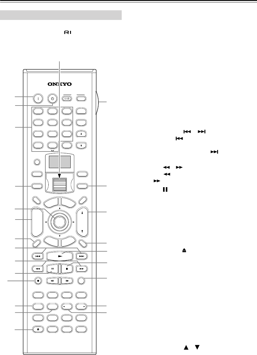
DVD mode is used to control an Onkyo DVD player con-
nected to the TX-NR901 via . To select DVD mode,
press the [MODE] button, and then roll the scroll wheel
until “DVD” appears on the display.
AON button
This button is used to turn on the DVD player.
BSTANDBY button
This button is used to set the DVD player to Standby.
CNumber/letter buttons
These buttons are used to enter title, chapter, and
track numbers and to enter times for locating specific
points in time.
DMODE button
This button is used with the scroll wheel to select the
remote controller modes. Press this button first, and
then roll the scroll wheel until “DVD” appears on the
display.
ETOP MENU button
This button is used to select the DVD-Video disc’s
top menu.
F[] [ ] [ ] [ ] & ENTER buttons
These buttons are used to navigate DVD-Video
menus and the DVD player’s onscreen setup menus.
The ENTER button is used to start playback of the
selected menu title, chapter, or track and to confirm
settings.
GCH/DISC +/– button
This button is used to select discs on a DVD changer.
HRETURN/EXIT button
This button is used to exit the DVD player’s
onscreen setup menu and to restart menu playback.
IDISPLAY button
This button is used to display information about the
current disc, title, chapter, or track, including the
elapsed time, remaining time, total time, and so on.
JPrevious/Next [ ]/[ ] buttons
The Previous [ ] button is used to select the previ-
ous chapter or track. During playback it selects the
beginning of the current chapter or track. The Next
[] button is used to select the next chapter or
track.
KFR/FF [ ]/[ ] buttons
The FR [ ] button is used to start fast reverse. The
FF [ ] button is used to start fast forward.
LPause [ ] button
This button is used to pause DVD playback.
MSTEP/SLOW [ ]/[ ] buttons
These buttons are used for frame-by-frame playback
and slow-motion playback.
DVD Mode
--
/
---
@.
-
'
/ABC DEF
PQRS TUV WXYZ
DIRECT TUNING
GHI JKL MNO
CAPS DELETE
LANGUAGE LOCATION
ALBUM AR
TIST GENRE
PLAYLIST
CUSTOM
DISPLAY
DIMMER
T
V/
VIDEO
SLEEP
RANDOMREC
STEP
/
SLOW
MUTING
ENTER
LAST MANGLE
SUBTITLE
AUDIO
MEMORY
SEARCHA-BREPEAT
ON STANDBY TV
TV CH
TV VOL
RC-549M
A
U
D
I
O
A
D
J
E
X
I
T
G
U
I
D
E
+10 0
CLEAR
123
456
789
INPUT
T
O
P
M
E
N
U
M
E
N
U
S
E
T
U
P
R
E
T
U
R
N
ZONE
2
INPUTMODE
MACRO
VOL
CH
DISC
TEST T
O
NE
CH SEL
PURE A
SURR
DIRECT
STEREO
Re-EQ
THX
A
ll
CH
ST
LEVEL
+
LEVEL
-
L NIGHT
AUDIO
SEL
DSP DSP
+
-
+
-
A
C
D
E
F
H
G
O
N
L
M
P
Q
R
I
J
BS
U
W
X
Y
Z
b
e
d
c
a
V
T
K
Scroll wheel
TX-NR901_En.book Page 16 Friday, August 15, 2003 7:48 PM

17
Remote Controller—Continued
NSUBTITLE button
This button is used to select subtitles.
OAUDIO button
This button is used to select foreign language
soundtracks and audio formats (e.g., Dolby Digital
or DTS).
PREPEAT button
This button is used to set the repeat playback func-
tions.
QA-B button
This button is used to set the A–B repeat playback
function.
ROpen/Close [ ] button
This button is used to open and close the disc tray.
SLIGHT button
This button is used to turn on or off the remote con-
troller’s illuminated buttons.
TINPUT button
This button is used to select the input source. Press
this button first, and then roll the scroll wheel until
“DVD” appears on the display.
Note:
While neither the [MODE] button nor [INPUT] but-
ton is illuminated, rolling the scroll wheel changes
both lines of the display.
UMENU button
This button is used to select the DVD-Video disc’s
menu.
VVOL Up/Down [ ]/[ ] button (xx)
This button is used to set the volume of the
TX-NR901.
WSETUP/GUIDE button
This button is used to access the DVD player’s
onscreen setup menus.
XMUTING button
This button is used to mute the TX-NR901. This
function can be set only with the remote controller.
YPlay [ ] button
This button is used to start DVD playback.
ZStop [ ] button
This button is used to stop DVD playback.
aRANDOM button
This button is used with the random playback func-
tion.
bANGLE button
This button is used to select different camera angles.
cLAST M button
This button is used with the last memory function,
which allows you to resume DVD playback from
where you left off.
dMEMORY button
This button is used with the memory playback func-
tion, which allows you to create a custom playlist of
titles, chapters, or tracks.
eSEARCH button
This button is used to search for titles, chapters,
tracks, and specific points in time.
TX-NR901_En.book Page 17 Friday, August 15, 2003 7:48 PM
18
Remote Controller—Continued
CD mode is used to control an Onkyo CD player con-
nected to the TX-NR901 via . To select CD mode,
press the [MODE] button, and then roll the scroll wheel
until “CD” appears on the display.
Boxed numbers are for MiniDisc mode (page 19).
AON button
This button is used to turn on the CD player.
BSTANDBY button
This button is used to set the CD player to Standby.
CNumber/letter buttons
These buttons are used to enter track numbers and to
enter times for locating specific points in time.
DMODE button
This button is used with the scroll wheel to select the
remote controller modes. Press this button first, and
then roll the scroll wheel until “CD” appears on the
display.
EENTER button
The ENTER button is used to confirm settings.
FCH/DISC +/– button
This button is used to select discs on a CD changer.
GDISPLAY button
This button is used to display information about the
current disc or track, including the elapsed time,
remaining time, total time, and so on.
HPrevious/Next [ ]/[ ] buttons
The Previous [ ] button is used to select the previ-
ous track. During playback it selects the beginning
of the current track. The Next [ ] button is used to
select the next track.
IFR/FF [ ]/[ ] buttons
The FR [ ] button is used to start fast reverse. The
FF [ ] button is used to start fast forward.
JPause [ ] button
This button is used to pause CD playback.
KREPEAT button
This button is used to set the repeat playback func-
tions.
LA-B button
This button is used to set the A–B repeat playback
function.
MOpen/Close [ ] button
This button is used to open and close the disc tray.
NLIGHT button
This button is used to turn on or off the remote con-
troller’s illuminated buttons.
OINPUT button
This button is used to select the input source. Press
this button first, and then roll the scroll wheel until
“CD” appears on the display.
Note:
While neither the [MODE] button nor [INPUT] but-
ton is illuminated, rolling the scroll wheel changes
both lines of the display.
PVOL Up/Down [ ]/[ ] button (xx)
This button is used to set the volume of the
TX-NR901.
QMUTING button
This button is used to mute the TX-NR901. This
function can be set only with the remote controller.
CD Mode
--
/
---
@.
-
'
/ABC DEF
PQRS TUV WXYZ
DIRECT TUNING
GHI JKL MNO
CAPS DELETE
LANGUAGE LOCATION
ALBUM AR
TIST GENRE
PLAYLIST
CUSTOM
DISPLAY
DIMMER
T
V/
VIDEO
SLEEP
RANDOMREC
STEP
/
SLOW
MUTING
ENTER
LAST MANGLE
SUBTITLE
AUDIO
MEMORY
SEARCHA-BREPEAT
ON STANDBY TV
TV CH
TV VOL
RC-549M
A
U
D
I
O
A
D
J
E
X
I
T
G
U
I
D
E
+10 0
CLEAR
123
456
789
INPUT
T
O
P
M
E
N
U
M
E
N
U
S
E
T
U
P
R
E
T
U
R
N
ZONE
2
INPUTMODE
MACRO
VOL
CH
DISC
TEST T
O
NE
CH SEL
PURE A
SURR
DIRECT
STEREO
Re-EQ
THX
A
ll
CH
ST
LEVEL
+
LEVEL
-
L NIGHT
AUDIO
SEL
DSP DSP
+
-
+
-
A
3
4
5
6
J
K
L
M
7
8
N
Q
R
S
V
U
T
P
O
9
1
2
3
4
5
6
7
8
9
0
A
B
C
D
F
E
G
I
H
J
B
Scroll wheel
TX-NR901_En.book Page 18 Friday, August 15, 2003 7:48 PM
19
Remote Controller—Continued
RPlay [ ] button
This button is used to start CD playback.
SStop [ ] button
This button is used to stop CD playback.
TRANDOM button
This button is used with the random playback func-
tion.
UMEMORY button
This button is used with the memory playback func-
tion, which allows you to create a custom playlist of
tracks.
VSEARCH button
This button is used to search for tracks and specific
points in time.
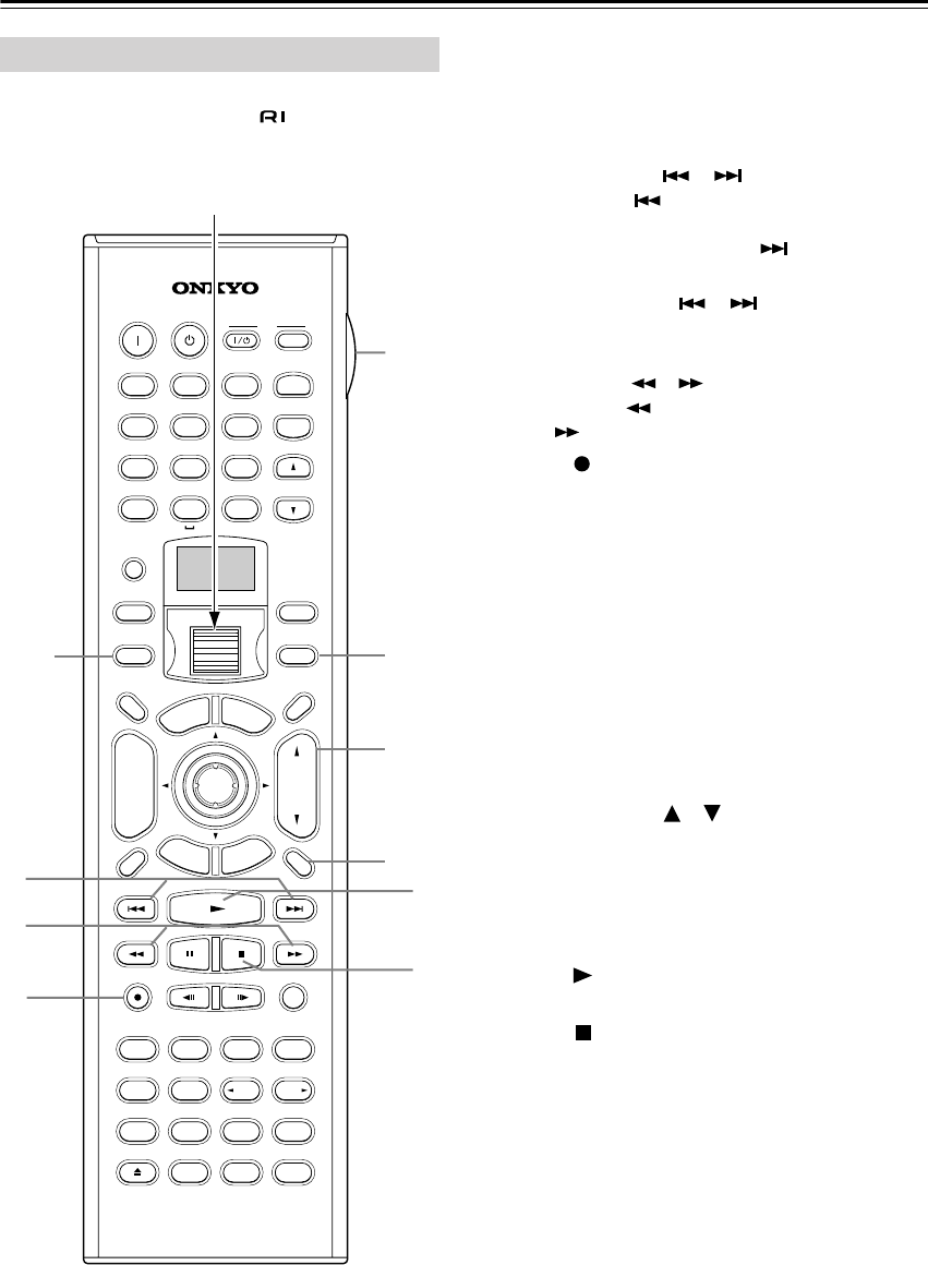
MiniDisc mode is used to control an Onkyo MiniDisc
recorder connected to the TX-NR901 via . To select
MiniDisc mode, press the [MODE] button, and then roll
the scroll wheel until “MD” appears on the display.
1ON button
This button is used to turn on the MiniDisc recorder.
2STANDBY button
This button is used to set the MiniDisc recorder to
Standby.
3Number/letter buttons
These buttons are used to enter track numbers and to
enter times for locating specific points in time.
4MODE button
This button is used with the scroll wheel to select the
remote controller modes. Press this button first, and
then roll the scroll wheel until “MD” appears on the
display.
5ENTER button
The ENTER button is used to confirm settings.
6DISPLAY button
This button is used to display information about the
current disc or track, including the elapsed time,
remaining time, total time, and so on.
7Previous/Next [ ]/[ ] buttons
The Previous [ ] button is used to select the previ-
ous track. During playback it selects the beginning
of the current track. The Next [ ] button is used to
select the next track.
8FR/FF [ ]/[ ] buttons
The FR [ ] button is used to start fast reverse. The
FF [ ] button is used to start fast forward.
9Pause [ ] button
This button is used to pause MiniDisc playback.
0REC [ ] button
This button is used to start MiniDisc recording.
AREPEAT button
This button is used to set the repeat playback func-
tions.
BEject [ ] button
This button is used to set eject the MiniDisc.
CLIGHT button
This button is used to turn on or off the remote con-
troller’s illuminated buttons.
DINPUT button
This button is used to select the input source. Press
this button first, and then roll the scroll wheel until
“MD” appears on the display.
Note:
While neither the [MODE] button nor [INPUT] but-
ton is illuminated, rolling the scroll wheel changes
both lines of the display.
EVOL Up/Down [ ]/[ ] button (xx)
This button is used to set the volume of the
TX-NR901.
FMUTING button
This button is used to mute the TX-NR901. This
function can be set only with the remote controller.
GPlay [ ] button
This button is used to start MiniDisc playback.
HStop [ ] button
This button is used to stop MiniDisc playback.
IRANDOM button
This button is used with the random playback func-
tion.
JMEMORY button
This button is used with the memory playback func-
tion, which allows you to create a custom playlist of
tracks.
MiniDisc Mode
TX-NR901_En.book Page 19 Friday, August 15, 2003 7:48 PM
20
Remote Controller—Continued
Tape mode is used to control an Onkyo cassette recorder
connected to the TX-NR901 via . To select Tape
mode, press the [MODE] button, and then roll the scroll
wheel until “AMP” appears on the display.
AMODE button
This button is used with the scroll wheel to select the
remote controller modes. Press this button first, and
then roll the scroll wheel until “AMP” appears on the
display.
BPrevious/Next [ ]/[ ] buttons
The Previous [ ] button is used to select the previ-
ous track. During playback it selects the beginning
of the current track. The Next [ ] button is used to
select the next track.
The Previous/Next [ ]/[ ] buttons make not
work properly with some cassette tapes depending
on how they were recorded.
CRewind/FF [ ]/[ ] buttons
The Rewind [ ] button is used to start rewind. The
FF [ ] button is used to start fast forward.
DREC [ ] button
This button is used to start tape recording.
ELIGHT button
This button is used to turn on or off the remote con-
troller’s illuminated buttons.
FINPUT button
This button is used to select the input source. Press
this button first, and then roll the scroll wheel until
“TAPE” appears on the display.
Note:
While neither the [MODE] button nor [INPUT] but-
ton is illuminated, rolling the scroll wheel changes
both lines of the display.
GVOL Up/Down [ ]/[ ] button (xx)
This button is used to set the volume of the
TX-NR901.
HMUTING button
This button is used to mute the TX-NR901. This
function can be set only with the remote controller.
IPlay [ ] button
This button is used to start tape playback.
JStop [ ] button
This button is used to stop tape playback.
Tape Mode
--
/
---
@.
-
'
/ABC DEF
PQRS TUV WXYZ
DIRECT TUNING
GHI JKL MNO
CAPS DELETE
LANGUAGE LOCATION
ALBUM AR
TIST GENRE
PLAYLIST
CUSTOM
DISPLAY
DIMMER
T
V/
VIDEO
SLEEP
RANDOMREC
STEP
/
SLOW
MUTING
ENTER
LAST MANGLE
SUBTITLE
AUDIO
MEMORY
SEARCHA-BREPEAT
ON STANDBY TV
TV CH
TV VOL
RC-549M
A
U
D
I
O
A
D
J
E
X
I
T
G
U
I
D
E
+10 0
CLEAR
123
456
789
INPUT
T
O
P
M
E
N
U
M
E
N
U
S
E
T
U
P
R
E
T
U
R
N
ZONE
2
INPUTMODE
MACRO
VOL
CH
DISC
TEST T
O
NE
CH SEL
PURE A
SURR
DIRECT
STEREO
Re-EQ
THX
A
ll
CH
ST
LEVEL
+
LEVEL
-
L NIGHT
AUDIO
SEL
DSP DSP
+
-
+
-
A
E
G
8
F
2
3
4
9
J
Scroll wheel
TX-NR901_En.book Page 20 Friday, August 15, 2003 7:48 PM
87
Using the Remote Controller with Other Components
You can use the TX-NR901’s remote controller (RC-
549M) to control your other AV components, including
those made by other manufacturers. To do this you can:
• Enter a remote control code for the component that
you want to control (e.g., DVD, TV, VCR).
•Learn commands directly from the other component’s
remote controller (see page 94).
•Use the Macro function to learn a sequence of actions
(see page 95).
•You can also edit the remote controller modes (see
page 97).
By entering the appropriate remote control code for each
of your components, you can control each component by
selecting the relevant remote controller mode: DVD, TV,
VCR, CBL (cable), or SAT (satellite).
Remote Control Codes for an Onkyo DVD
player
The remote control code that you use with an Onkyo
DVD player depends on whether it’s connected via ,
as follows:
5001:
Use this code if you’ve connected an cable
and an RCA/phono analog audio cable to your
DVD player. This is the default setting, so if
you’re using , you don’t need to change it.
Point the remote controller at the TX-NR901 to
operate the DVD player.
5002:
Use this code if your DVD player doesn’t have
an socket, or you’re not using . Point
the remote controller at the DVD player to
operate it.
Entering a Remote Control Code
1
Look up the appropriate remote
control code for the component.
See “Remote Control Codes” on
page 88
2
Press and hold down the [CUS-
TOM] button for more than three
seconds.
The remote controller enters Custom
mode.
3
Roll the scroll wheel to select
PRGRM, and then press the
scroll wheel.
4
Roll the scroll wheel to select the
the remote controller mode you
want to use with the component,
and then press the scroll wheel.
The following remote controller modes
can be selected: DVD, TV, VCR, CBL,
or SAT.
5
Use the number buttons to enter
the 4-digit remote control code.
If the code is accepted, the following
appears on the display for awhile, and
then the normal display reappears.
If the code is not accepted, after the
message “RETRY” has been displayed,
the code entry display reappears, and
you should try entering the code again.
To cancel this procedure at any point,
press the [CUSTOM] button.
6
Select the remote controller
mode, point the remote control-
ler at the component, and check
its operation.
The remote controller buttons that can
be used in DVD mode are shown on
page 17. Those that can be used with
the TV, VCR, CBL, and SAT modes are
listed on pages 92 and 93.
7_Appendix_En Page 87 Monday, September 8, 2003 4:03 PM

88
Using the Remote Controller with Other Components
—Continued
Remote Control Codes
When two or more codes are given,
try each one in turn, and choose the
one that works best.
DVD (DVD player)
Manufacturer Control code
Aiwa 5010
Akai 5019
Apex 5015, 5016
CyberHome 5027
Denon 5017, 5020
GE 5003
Hitachi 5009
JVC 5023
Kenwood 5017
Magnavox 5004, 5021
Marantz 5025, 5026
Mitsubishi 5005
Onkyo 5001, 5002
Panasonic 5011, 5017, 5020
Philips 5004, 5021, 5028
Pioneer 5006
Proscan 5003
RCA 5003
Sanyo 5012
Sony 5007, 5013, 5018, 5029
Technics 5020
Thomson 5022, 5024
Toshiba 5008, 5021
Xbox 5022
Yamaha 5020
Zenith 5014, 5021
SAT (satellite receiver)
Manufacturer Control code
Alba 4014, 4017, 4025, 4027
Allsat 4015, 4027
Alltech 4022, 4025
Amstrad 4013, 4019, 4025, 4030,
4031
Anglo 4025
Ankaro 4025
Anttron 4017
Apollo 4017
Arcon 4016
Armstrong 4013
Asat 4016
Astra 4013, 4016, 4024
Astro 4019, 4020
AudioTon 4015
Bush 4012, 4014
Condor 4024
Conrad 4024
Cosat 4015, 4023
Crown 4013
Daewoo 4016, 4017, 4025
Diamond 4022
Dishnet 4008
Dual 4016
Echostar 4010, 4018, 4025
Einhell 4013, 4017, 4025
Elta 4015, 4017
Engel 4025
Eurosat 4013, 4022
Eurosky 4013, 4024
Eurostar 4024
Fagor 4015, 4023
Ferguson 4012
Fidelity 4030
Fracarro 4017
FTE 4025, 4030
Fuba 4017
Galaxis 4015, 4023
GE 4001, 4002
General Instruments 4003
GMI 4013
Grundig 4021, 4029, 4031
Hinari 4017
Hirschmann 4019, 4035
Hitachi 4036, 4037
Hughes Network
Systems 4011
Huth 4013, 4015, 4024
Imperial 4014
Intertronic 4013
Intervision 4015, 4023, 4024
Johansson 4015
JVC 4009, 4021
Kathrein 4025
Kolon 4017
K-SAT 4025
Kyostar 4017
Lasat 4013, 4020, 4024
Lenco 4016, 4017, 4025
Lennox 4023
Loewe 4013
Lorenzen 4024
Macab 4022
Manhattan 4015, 4020, 4023
Maspro 4021, 4025
Matsui 4021
Mediamarkt 4013
Medion 4025
Metronic 4013, 4017, 4020
Micro Technology 4025
Minerva 4021
Morgan's 4013, 4015, 4025
Mysat 4025
Neuhaus 4019, 4023, 4024, 4025
Neusat 4025
Nikko 4013, 4025, 4027
Nokia 4033
Nordmende 4017, 4020
Oceanic 4022
Octagon 4016, 4017
Okano 4013
Optex 4015, 4023
Orbit 4016
Orbitech 4017, 4019
Pace 4012, 4026, 4031
Pacific 4022
Palladium 4013, 4017, 4021
Palsat 4019
Panasonic 4006, 4031
Panda 4024
Philips 4021, 4029
Phonotrend 4015, 4023
Predki 4017
Premier 4023
SAT (satellite receiver)
Manufacturer Control code
Primestar 4007
Proscan 4001, 4002
Protek 4022
Pye 4021
Quelle 4024
Radix 4035
RCA 4001, 4002
Roadster 4025
Rover 4025
Saba 4014, 4020, 4024, 4027
Samsung 4017
Satcom 4024
SatPartner 4017, 4020, 4027, 4030
Schneider 4029
Sedea Electronique 4017
Seemann 4013
SEG 4017, 4028
Seleco 4015, 4023
Skymaster 4025, 4034
Skyvision 4015
Sony 4005, 4031
Strong 4016, 4017, 4020
Sunstar 4013
Techniland 4015, 4023
TechniSat 4019
Teco 4013, 4016
Teleciel 4027
Telefunken 4017
Teleka 4013
Telemaster 4020
Telewire 4015, 4023
Tensai 4016
Thomson 4024, 4025
Thorens 4022
Tonna 4015, 4023, 4025
Toshiba 4004
Triasat 4019
Tristar 4016
Unisat 4013
Universum 4021, 4024
Vortec 4017
Wela 4025
Zehnder 4020
Zenith 4032
SAT (satellite receiver)
Manufacturer Control code
7_Appendix_En Page 88 Monday, September 8, 2003 4:03 PM

89
Using the Remote Controller with Other Components
—Continued
CBL (cable receiver)
Manufacturer Control code
ABC 3001, 3002, 3021
Archer 3006
Cabletime 3028, 3032
Cableview 3004
Contec 3009
Eastern 3010
GE 3001, 3002
Gemini 3011
General Instruments 3002, 3022
Grundig 3031
Hamlin 3012
Hitachi 3002
Jerrold 3002, 3011, 3013, 3021,
3022, 3023, 3026
Magnavox 3014
Memorex 3015
Movie Time 3016
NEC 3003
Nokia 3033
NSC 3016
Oak 3009
Panasonic 3020
Philips 3007, 3008, 3014
Pioneer 3017, 3024
Proscan 3001, 3002
RCA 3004, 3020, 3022
Realistic 3006
Sagem 3034
Salora 3029
Samsung 3017
Signature 3002
Sprucer 3020
Standard Component 3018
Starcom 3011, 3021
Stargate 3011
Tele+1 3030
Tocom 3013
United Cable 3021, 3023
Universal 3005, 3006
Videoway 3025
View Star 3009, 3014, 3016
Zenith 3019
VCR
Manufacturer Control code
Aiwa 2012, 2046, 2047
Akai 2003, 2004, 2022
Alba 2033, 2041, 2044, 2045,
2047
Anitech 2033
ASA 2034
Baird 2036
Bell & Howell 2007
Blaupunkt 2039, 2042
Bush 2033, 2041, 2044, 2045,
2047
Canon 2010, 2011
Carver 2014
Cimline 2033
Citizen 2008, 2009
Colortyme 2005
Craig 2008
Crown 2033
Curtis Mathes 2001, 2005, 2008, 2009,
2010, 2011, 2023, 2026
Cyrus 2034
Daewoo 2012
Dansai 2033
Decca 2034
Dimensia 2001, 2026
Dumont 2034, 2036, 2037
Elcatech 2033
Emerson 2003, 2010, 2012, 2022
ESC 2043
Ferguson 2035
Finlandia 2034, 2036
Finlux 2034, 2036, 2037
Firstline 2033, 2041
Fisher 2007, 2030, 2036
Fuji 2004, 2010, 2024
Funai 2012
Garrard 2012
GE 2001, 2002, 2008, 2010,
2011, 2023, 2025, 2026
GEC 2034
GoldHand 2033
GoldStar 2005, 2009
Goodmans 2031, 2033
Gradiente 2012
Graetz 2036, 2043
Granada 2030, 2034, 2036
Grandin 2033
Grundig 2029, 2033, 2034, 2039,
2040, 2042, 2044
Harman Kardon 2005
HCM 2033, 2044
Hinari 2028, 2033, 2043, 2044,
2047
Hitachi 2013, 2021, 2025, 2028,
2037, 2038, 2043
Ingersol 2028
Interfunk 2034
ITT 2030, 2036, 2043, 2048
JC Penney 2005, 2006, 2007, 2008,
2010, 2011, 2013, 2014,
2021
Jensen 2013
JVC 2005, 2006, 2007, 2009,
2032, 2035, 2040, 2048
Kaisui 2033
Kendo 2041, 2046
Kenwood 2005, 2006, 2007, 2009
Kodak 2010
Loewe 2028, 2034
Logik 2028, 2043
Luxor 2030, 2031, 2036
Magnavox 2010, 2011, 2014, 2019,
2020
Marantz 2005, 2006, 2007, 2009,
2010, 2014, 2031, 2034
Matsui 2028, 2041, 2046, 2047
Matsushita 2010
Memorex 2007, 2008, 2010, 2012,
2019, 2030, 2036
Metz 2039
MGA 2022
Minerva 2039
Minolta 2013, 2021
Mitsubishi 2013, 2022, 2032, 2034
Motorola 2010
MTC 2008
Multitech 2008, 2012, 2033
VCR
Manufacturer Control code
NEC 2005, 2006, 2007, 2009,
2032
Neckermann 2034
Nesco 2033
NOBLEX 2008
Nokia 2030, 2036, 2043
Nordmende 2048
Okano 2046
Olympus 2010
Optonica 2017
Orion 2028, 2041, 2045, 2046,
2047
Osaki 2033
Otto Versand 2034
Palladium 2033
Panasonic 2010, 2011, 2042
Pentax 2013, 2021, 2025, 2037
Pentex Research 2009
Philco 2010, 2011, 2014
Philips 2010, 2014, 2017, 2034,
2048
Phonola 2034
Pioneer 2006, 2013, 2032, 2034
Proline 2044
Proscan 2001, 2002, 2026
Pye 2034
Quasar 2010, 2011
Quelle 2034
Radio Shack 2017
Radio Shack/Realistic 2007, 2008, 2010, 2011,
2012, 2017
Radiola 2034
RCA 2001, 2002, 2003, 2008,
2010, 2013, 2021, 2023,
2025, 2026, 2027
Realistic 2007, 2008, 2010, 2011,
2012, 2017
Rex 2048
Roadstar 2033, 2043
Runco 2019
Saba 2040, 2048
Saisho 2028, 2041
Salora 2030
Samsung 2008, 2043, 2049
Sansui 2006, 2032
Sanyo 2007, 2008, 2030, 2036
Saville 2047
SBR 2034
Schaub Lorenz 2036
Schneider 2033, 2034
Scott 2015
Sears 2007, 2010, 2013, 2021
SEG 2043
SEI 2028, 2034
Sharp 2016, 2017, 2031
Shintom 2004, 2033, 2036
Shorai 2028
Siemens 2034, 2036, 2039
Singer 2010
Sinudyne 2028, 2034
Sonolor 2030, 2031
Sony 2004, 2018, 2024
VCR
Manufacturer Control code
7_Appendix_En Page 89 Monday, September 8, 2003 4:03 PM

90
Using the Remote Controller with Other Components
—Continued
VCR
Manufacturer Control code
STS 2010, 2021
Sunkai 2046
Sylvania 2010, 2011, 2012, 2014
Symphonic 2012
Tandy 2007
Tatung 2034
Teac 2012
Technics 2010, 2042
Teknika 2010, 2012
Telefunken 2048
Thomson 2048
Thorn 2035, 2036
Toshiba 2013, 2015, 2022, 2034,
2048
Totevision 2008
Uher 2043
Unitech 2008
Universum 2034, 2039, 20403
Vector Research 2005, 2006
Video Concepts 2005, 2006, 2022
Wards 2008, 2010, 2012, 2013,
2017, 2021, 2027
XR-12000 2010, 2012
Yamaha 2005, 2006, 2007, 2009
Yoko 2043
Zenith 2004, 2019, 2024
TV
Manufacturer Control code
Admiral 1026, 1040, 1062
Akai 1002, 1067
Akura 1045
Alba 1035, 1043
Amplivision 1063
Amstrad 1035, 1067
Amtron 1009
Anam National 1003, 1009
Anitech 1035
AOC 1004, 1005, 1006
Arc en Ciel 1066
Arcam 1063
ASA 1040
Audiovox 1009
Autovox 1040, 1068
Baird 1069
Bang & Olufsen 1040
Baur 1036, 1054, 1055, 1058,
1059, 1068
Beko 1052
Bell & Howell 1010, 1017
Binatone 1063
Blaupunkt 1041, 1042, 1044, 1058,
1059
Boots 1063
Brionvega 1040
Bruns 1040
BSR 1048
Bush 1035, 1043, 1048, 1050,
1053, 1057
Cascade 1035
Celebrity 1002
Century 1040
Cimline 1035, 1043
Citizen 1004, 1006, 1009, 1017,
1022, 1025
Clatronic 1052
Colortyme 1004, 1006
Condor 1052
Contec 1035
Contec/Cony 1007, 1009
Continental Edison 1066
Craig 1009
Crosley 1040
Crown 1009, 1014, 1035, 1052
Curtis Mathes 1001, 1004, 1006, 1010,
1017, 1022, 1025, 1034
Daewoo 1004, 1005, 1006, 1025,
1035, 1053
Daytron 1004, 1006, 1025, 1035
Decca 1067
Dimensia 1001, 1034
Dixi 1035
Dual 1057, 1068
Dumont 1004, 1039, 1040
Electroband 1002
Electrohome 1002, 1003, 1004, 1006,
1008
Elta 1035
Emerson 1004, 1006, 1007, 1009,
1010, 1017, 1025, 1027,
1029, 1033, 1040
Envision 1004, 1006
Erres 1037
Europhon 1067
Fidelity 1068
Finlux 1039, 1040, 1067
Firstline 1035, 1043, 1048, 1049,
1063
Fisher 1010, 1017, 1052, 1063,
1068
Formenti 1040
Frontech 1045, 1062
Funai 1009, 1045, 1048
GE 1001, 1003, 1004, 1006,
1011, 1012, 1019, 1034
GEC 1038, 1063, 1067, 1069
Geloso 1035
Genexxa 1062
GoldStar 1004, 1005, 1006, 1007,
1008, 1025, 1047, 1063
Goodmans 1043, 1053, 1063
Gorenje 1052
Graetz 1062, 1069
Granada 1063, 1067
Grundig 1039, 1041, 1042, 1058,
1059, 1064
Hallmark 1004, 1006
Hanseatic 1060, 1068
Hantarex 1067
HCM 1035
Hinari 1035, 1043
Hitachi 1004, 1006, 1007, 1013,
1027, 1038, 1062, 1063,
1069
Huanyu 1053
ICE 1045, 1063
Imperial 1052
Infinity 1014
Inno Hit 1056, 1067
Interfunk 1055, 1062, 1066, 1069
Intervision 1045, 1063
ITT 1062, 1068, 1069
JBL 1014
TV
Manufacturer Control code
JC Penney 1001, 1004, 1005, 1006,
1011, 1012, 1016, 1019,
1022, 1025, 1034
Jensen 1004, 1006
JVC 1007, 1012, 1013, 1015,
1033
Kaisui 1035, 1063
Kapsch 1062, 1069
Kathrein 1060
Kawasho 1002, 1004, 1006
Kendo 1043
Kenwood 1004, 1006, 1008
Kloss Novabeam 1009
Korting 1040
KTV 1009, 1025
LG 1005
Loewe 1014, 1040, 1055
Luxman 1004, 1006
LXI 1001, 1006, 1010, 1014,
1016, 1017, 1034
M Electronic 1035, 1053, 1062, 1063
Magnadyne 1040, 1067, 1068
Magnafon 1067
Magnavox 1004, 1006, 1008, 1014,
1018, 1020
Marantz 1004, 1006, 1014, 1060
Matsui 1035, 1043, 1048, 1050,
1063, 1064, 1067, 1068
Megatron 1006
Memorex 1005, 1006, 1010, 1017,
1035
Metz 1040, 1051, 1058
MGA 1004, 1005, 1006, 1008
Minerva 1039, 1058, 1059, 1064
Mitsubishi 1004, 1005, 1006, 1008,
1040, 1055, 1058
Mivar 1047, 1056, 1067
Motorola 1003, 1026
MTC 1004, 1005, 1006, 1022,
1055
Multitech 1009, 1035
NAD 1006, 1016
NEC 1003, 1004, 1005, 1006
Neckermann 1040, 1041, 1054, 1059,
1060
Nikkai 1045
Nikko 1006
Oceanic 1062
Onwa 1009
Optonica 1021, 1026
Orion 1029, 1043, 1048, 1049,
1050, 1067, 1068
Osaki 1045, 1063
Otto Versand 1036, 1041, 1043, 1054,
1055, 1058, 1059, 1060,
1063
Palladium 1052
Panasonic 1003, 1012, 1014, 1031,
1044, 1046, 1051, 1061,
1062, 1069
Pathe Marconi 1066
Philco 1003, 1004, 1005, 1006,
1007, 1008, 1014, 1018,
1040
TV
Manufacturer Control code
7_Appendix_En Page 90 Monday, September 8, 2003 4:03 PM

91
Using the Remote Controller with Other Components
—Continued
TV
Manufacturer Control code
Philips 1003, 1004, 1007, 1008,
1014, 1018, 1019, 1020,
1037, 1038, 1040, 1053
1059, 1060
Phoenix 1040
Phonola 1037, 1040
Pioneer 1004, 1006, 1027, 1062
Portland 1004, 1005, 1006, 1025
Price Club 1022
Prism 1012
Profex 1035
Proline 1049
Proscan 1001, 1034
Protech 1035, 1045, 1063
Proton 1004, 1006, 1007
Pye 1037
Quasar 1003, 1012, 1031
Quelle 1036, 1039, 1054, 1055,
1058, 1059, 1068
Radio Shack 1010, 1017, 1034
Radio Shack/Realistic 1001, 1004, 1006, 1007,
1009, 1010, 1017, 1021,
1025
Radiola 1037
Radiomarelli 1040, 1067
RCA 1001, 1003, 1004, 1005,
1006, 1008, 1027, 1034
Realistic 1010, 1017, 1034
Rex 1045, 1062
RFT 1040
Roadstar 1035, 1045
Saba 1040, 1062, 1066, 1069
Saisho 1035, 1043, 1045, 1067,
1068
Salora 1062
Sambers 1056, 1067
Sampo 1004, 1006, 1025
Samsung 1004, 1005, 1006, 1007,
1008, 1022, 1025, 1035,
1045, 1047, 1052, 1056
1060, 1063, 1065
Sansui 1029
Sanyo 1004, 1010, 1017
SBR 1037, 1038
Schaub Lorenz 1069
Schneider 1068
Scott 1004, 1006, 1007, 1009
Sears 1001, 1004, 1006, 1008,
1010, 1015, 1016, 1017,
1028, 1034
SEG 1045, 1063
SEI 1036, 1040, 1048, 1067,
1068
Seleco 1062
Sharp 1004, 1006, 1007, 1021,
1023, 1025, 1026
Shorai 1048
Siarem 1040, 1067
Siemens 1041, 1042, 1058, 1059
Singer 1040
Sinudyne 1036, 1040, 1043, 1067,
1068
Solavox 1062
Sonoko 1035
Sonolor 1062
Sony 1002, 1030, 1032, 1036,
1054
Soundesign 1004, 1006, 1009
Starlite 1009
Stern 1062
Sunkai 1043, 1048, 1049, 1050
Sylvania 1004, 1006, 1008, 1014,
1018, 1020
Symphonic 1009, 1028
Tandy 1026, 1062, 1063
Tashiko 1038, 1063
Tatung 1003, 1063, 1067
Tec 1063
Technics 1012, 1044, 1061
Techwood 1004, 1006, 1012
Teknika 1004, 1005, 1006, 1007,
1009, 1022, 1025, 1031
Teleavia 1066
Telecaption 1024
Telefunken 1066
Teletech 1035
Teleton 1063
Tensai 1048
Thomson 1066
Thorn 1054, 1055, 1058
Toshiba 1010, 1016, 1017, 1022,
1024, 1039
Totevision 1025
Triumph 1067
Universal 1011, 1019
Universum 1045, 1052, 1058
Voxson 1040, 1062
Waltham 1063
Wards 1001, 1004, 1005, 1006,
1008, 1011, 1014, 1018,
1019, 1020, 1021, 1034
Watt Radio 1068
Wega 1040
Yamaha 1004, 1005, 1006, 1008
Yoko 1045, 1063
Zenith 1004
TV
Manufacturer Control code
7_Appendix_En Page 91 Monday, September 8, 2003 4:03 PM
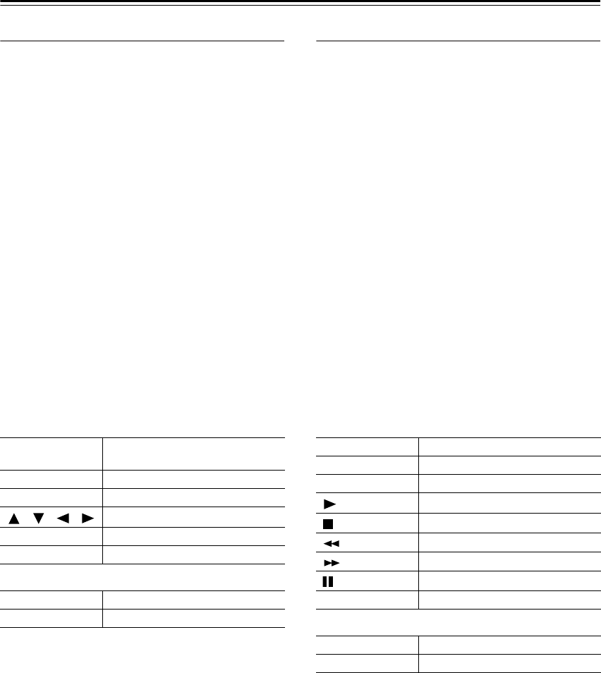
92
Using the Remote Controller with Other Components
—Continued
Controlling a Satellite Receiver
1. Press the [MODE] button, and then roll the scroll
wheel to select SAT.
2. Point the remote controller at your satellite
receiver, and use the following buttons (you must
enter appropriate remote control code first).
The following buttons control the TX-NR901.
Controlling a VCR
1. Press the [MODE] button, and then roll the scroll
wheel to select VCR.
2. Point the remote controller at your VCR, and use
the following buttons (you must enter appropriate
remote control code first).
The following buttons control the TX-NR901.
[ON], [STANDBY]
Set the satellite receiver to On or
Standby
[MENU]
Display menu
[CH/DISC]
Select satellite channels
[ ]/[ ]/[ ]/[ ]
Select menu items
[ENTER]
Confirm selection
Number buttons
Enter numbers
[VOL]
Adjust the TX-NR901 volume
[MUTING]
Mute the TX-NR901
[ON], [STANDBY]
Set the VCR to On or Standby
[CH/DISC]
Select TV channels
[TV INPUT]
Select TV or VCR input
[]
Play
[]
Stop
[]
Rewind
[]
Fast forward
[]
Pause
Number buttons
Enter numbers
[VOL]
Adjust the TX-NR901 volume
[MUTING]
Mute the TX-NR901
7_Appendix_En Page 92 Monday, September 8, 2003 4:03 PM
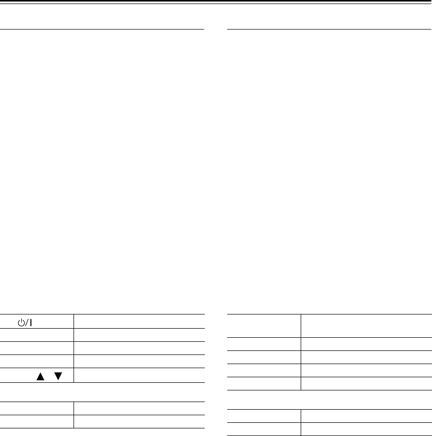
93
Using the Remote Controller with Other Components
—Continued
Controlling a TV
1. Press the [MODE] button, and then roll the scroll
wheel to select TV.
2. Point the remote controller at your satellite
receiver, and use the following buttons (you must
enter appropriate remote control code first).
The following buttons control the TX-NR901.
Controlling a Cable Receiver
1. Press the [MODE] button, and then roll the scroll
wheel to select CBL.
2. Point the remote controller at your satellite
receiver, and use the following buttons (you must
enter appropriate remote control code first).
The following buttons control the TX-NR901.
TV [ ]
TV on/off
TV CH [+]/[–]
Select TV channels
[ENTER]
Confirm selection
Number buttons
Enter numbers
TV VOL [ ]/[ ]
Adjust the TV volume
[VOL]
Adjust the TX-NR901 volume
[MUTING]
Mute the TX-NR901
[ON], [STANDBY]
Set the cable receiver to On or
Standby
[CH/DISC]
Select cable channels
[ENTER]
Confirm selection
[TV INPUT]
Select TV or VCR input
Number buttons
Enter numbers
[VOL]
Adjust the TX-NR901 volume
[MUTING]
Mute the TX-NR901
7_Appendix_En Page 93 Monday, September 8, 2003 4:03 PM

94
Using the Remote Controller with Other Components
—Continued
You can teach the TX-NR901’s remote controller new
commands simply by transmitting commands from
another remote controller one at time. For example, by
transmitting the Play and Stop commands from your CD
player’s remote controller, the TX-NR901’s remote con-
troller can be taught to transmit those commands when
its Play [ ] and Stop [ ] buttons are pressed in CD
mode.
Note:
• The following buttons cannot be taught new com-
mands: [LIGHT], [CUSTOM], [MACRO], [MODE],
[INPUT], [ZONE 2], and the scroll wheel button.
Learning Commands from Another
Remote Controller
1
Press and hold the [CUSTOM]
button for more than three sec-
onds.
The remote controller enters Custom
mode.
2
Roll the scroll wheel to select
LEARN, and then press the scroll
wheel.
3
Roll the scroll wheel to select the
the remote controller mode you
want to teach a new command,
and then press the scroll wheel.
The following remote controller modes
can be selected: DVD, TV, VCR, CBL,
or SAT.
4
On the TX-NR901’s remote con-
troller, press the button you want
to teach the new command.
If you press a button that cannot be
taught a new command, the message
“RETRY” appears and you should
press another button.
5
Point the remote controllers at
each other, about 2 to 6 inches
(5–15 cm) apart, and then, on the
other remote controller, press the
button whose command you
want to learn.
When the command has been learnt
successfully, “OK” appears on the dis-
play. You may need to press the button
several times.
If the command is not learnt success-
fully, after the message “FAIL” has
been displayed, the mode select display
reappears (step 3), and you should try
again.
6
To teach the TX-NR901’s remote
controller more new commands,
repeat steps 3 through 5.
Press the [CUSTOM] button when
you’ve finished.
7_Appendix_En Page 94 Monday, September 8, 2003 4:03 PM
95
Using the Remote Controller with Other Components
—Continued
With the Macro function you can program the remote
controller to perform a sequence of actions with one
press of a button. For example, normally you need to per-
form the following actions to use a CD player that’s con-
nected to the TX-NR901:
1. Press the scroll wheel, (to select AMP mode).
2. Press the [ON] button (to turn on the TX-NR901).
3. Roll the scroll wheel to select CD (to select the CD
remote controller mode and the CD input source).
4. Press the Play [ ] button (to start the CD player).
With the Macro function you can program the remote
controller to do all of this with one press of a button.
Making Macros
You can make up to eight macros, and each macro can
perform up to eight actions.
Running Macros
Programmed macros can be run as follows.
Using Macros
1
Press and hold the [CUSTOM]
button for more than three sec-
onds.
The remote controller enters Custom
mode.
2
Roll the scroll wheel to select
MACRO, and then press the
scroll wheel.
3
Roll the scroll wheel to select
EDIT, and then press the scroll
wheel.
4
Roll the scroll wheel to select a
macro, and then press the scroll
wheel.
Macros are numbered from 1 to 8.
Macro #1 selected
Action #1
5
On the remote controller, press
the buttons whose actions you
want to program into the macro
in the order you want them per-
formed.
To program the CD example in the left
column into a macro: press the scroll
wheel, press the [ON] button, roll the
scroll wheel to select CD, press the
scroll wheel, and then press the Play
[] button.
Actions are numbered from 1 to 8.
After each button is pressed, “SET” fol-
lowed by “KEY” is displayed.
To add an action that selects an input
source for the main room or Zone 2,
press the [INPUT] button or [ZONE 2]
button, respectively, roll the scroll
wheel to select the input source, and
then press the scroll wheel.
6
When you’ve finished, press the
[MACRO] button.
After the following appears on the dis-
play, the display returns to normal.
1
Press the [MACRO] button.
2
Press the number button corre-
sponding to the macro’s number.
The actions in the macro are performed
in the order in which they were pro-
grammed.
Macro #1 selected
8 actions learnt
7_Appendix_En Page 95 Monday, September 8, 2003 4:03 PM

96
Using the Remote Controller with Other Components—Continued
Naming Macros
You can name your macros as follows. Names may con-
tain of up to five characters.
1Press and hold the [CUSTOM]
button for more than three sec-
onds.
The remote controller enters Custom
mode.
2Roll the scroll wheel to select
MACRO, and then press the
scroll wheel.
3Roll the scroll wheel to select
NAME, and then press the scroll
wheel.
4Roll the scroll wheel to select the
number of the macro that you
want to name, and then press the
scroll wheel.
5Roll the scroll wheel to select a
character, and then press the
scroll wheel to set it.
The following characters are available.
1st character
Macro #1 selected
0 1 2 3 4 5 6 7 8 9 A B C D E F G H I J
K L M N O P Q R S T U V W X Y Z + –
= < > _ / space
_
1st character set
6Repeat step 5 until you’ve
entered all 5 characters.
The previous menu reappears.
If the name you are entering consists of
less than five characters, enter spaces at
the end to make it up to five.
7_Appendix_En Page 96 Monday, September 8, 2003 4:03 PM

97
Using the Remote Controller with Other Components—Continued
Adding New Remote Controller Modes
You can add additional modes (DVD, TV, VCR, CBL,
SAT) to the remote controller. This is useful if, for exam-
ple, you have several DVD players or TVs.
Reordering the Remote Controller Modes
You can change the order in which the remote controller
modes appears when you roll the scroll wheel. The posi-
tion of the AMP mode cannot be changed.
Editing Remote Controller Modes
1Press and hold the [CUSTOM]
button for more than three sec-
onds.
The remote controller enters Custom
mode.
2Roll the scroll wheel to select
MODE, and then press the scroll
wheel.
3Roll the scroll wheel to select
ADD, and then press the scroll
wheel.
4Roll the scroll wheel to select the
type of mode you want to add,
and then press the scroll wheel.
You can add up to 5 additional DVD
modes, 3 TV modes, 2 VCR modes,
and 2 CBL modes.
1Press and hold the [CUSTOM]
button for more than three sec-
onds.
The remote controller enters Custom
mode.
2Roll the scroll wheel to select
MODE, and then press the scroll
wheel.
3Roll the scroll wheel to select
SORT, and then press the scroll
wheel.
4Roll the scroll wheel to select the
mode you want to move, and
then press the scroll wheel.
5Roll the scroll wheel to select the
mode before which you want to
insert the specified mode, and
then press the scroll wheel.
Here the specified mode will be
inserted before the “VCR” mode.
If the move is successful, after “OK”
has been displayed, the SORT display
(step 3) reappears.
7_Appendix_En Page 97 Monday, September 8, 2003 4:03 PM

98
Using the Remote Controller with Other Components—Continued
Deleting Remote Controller Modes
You can delete remote controller modes that you don’t
need, such as modes for components that you don’t have.
The AMP mode cannot be deleted.
Assigning Remote Controller Modes
With this function you can assign a remote controller
mode to an input source. This is useful when you con-
nect, say, a CD recorder to the TAPE IN/OUT sockets. In
this case it’s convenient to assign the remote controller’s
CD mode to the TAPE input source.
1Press and hold the [CUSTOM]
button for more than three sec-
onds.
The remote controller enters Custom
mode.
2Roll the scroll wheel to select
MODE, and then press the scroll
wheel.
3Roll the scroll wheel to select
DEL, and then press the scroll
wheel.
4Roll the scroll wheel to select the
mode you want to delete, and
then press the scroll wheel.
If the mode is deleted successfully,
after “OK” has been displayed, the
DEL display (step 3) reappears.
1Press and hold the [CUSTOM]
button for more than three sec-
onds.
The remote controller enters Custom
mode.
2Roll the scroll wheel to select
MODE, and then press the scroll
wheel.
3Roll the scroll wheel to select
ASSIGN, and then press the
scroll wheel.
4Roll the scroll wheel to select the
mode you want to assign, and
then press the scroll wheel.
5Roll the scroll wheel to select the
input source you want to assign
to the specified mode, and then
press the scroll wheel.
If the assignment is successful, after
“OK” has been displayed, the ASSIGN
display (step 3) reappears.
7_Appendix_En Page 98 Monday, September 8, 2003 4:03 PM

99
Using the Remote Controller with Other Components—Continued
You can reset the remote controller to its default settings.
Resetting the Remote Controller
1Press and hold the [CUSTOM]
button for more than three sec-
onds.
The remote controller enters Custom
mode.
2Roll the scroll wheel to select
MODE, and then press the scroll
wheel.
3Roll the scroll wheel to select
RESET, and then press the scroll
wheel.
4Roll the scroll wheel to select
YES, and then press the scroll
wheel.
The remote controller is reset to its
default settings.
7_Appendix_En Page 99 Monday, September 8, 2003 4:03 PM