Philips Electronics M145 LCD TV User Manual
Philips Electronics Industries (Taiwan) Ltd LCD TV Users Manual
Users Manual
Page 1 of 1320wn6

Product Information
Product Features • Technical Specifications • Resolution & Preset
Modes • Philips Pixel Defect Policy • Automatic Power Saving •
Physical Specification • Pin Assignment • Product Views
Product Features
320WN6
zLess management effort for maximum productivity
{Multiple displays form a daisy chain to show uniform
{Monitor is network controllable for remote management
{Input connectors: CVBS, S-video, SCART, YPbPr, and RF (TV
input)
zBetter front of screen experience
{Motion adaptive deinterlacing for razor sharp images
{3D comb filter separates color for a razor-sharp image
{WXGA, wide format 1366 x 768 resolution for sharper display
{Adaptive brightness intensifier technology
{Ready to display SDTV, EDTV, and HDTV formats
zGreat convenience
{Zoom function to enable tiled matrix application
{Support hight-bandwidth digital content protection decryption
{Split screen for dual video/PC display
{Picture in picture for public display
* RF(TV input) is only available for 320WN6QS
RETURN TO TOP OF THE PAGE
Technical Specifications*
LCD PANEL
• Type TFT LCD
• Screen size 31.51inch
• Pixel Pitch 0.17 x 0.511 mm
• LCD Panel type 1366 x 768 pixels
R.G.B. vertical stripe
Hard coating surface, anti-glare polarizer
• Effective viewing area 697.7 x 392.2 mm
Page 1 of 8Product Information
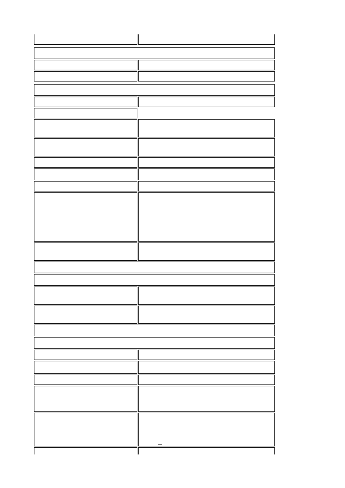
• Display Colors 8 bits interface (16.7M colors)
PC SCANNING
• Vertical refresh rate 56Hz-75Hz
• Horizontal frequency 30kHz-63kHz
PC VIDEO
• Video dot rate < 85 MHz
• Input impedance
- Video 75 ohm
- Sync 2.2K ohm
• Input signal levels 0.7 Vpp
• Sync input signal Separate sync
• Sync polarities Positive and negative
• Input Frequency
WXGA Hsync 48 kHz, Vsync 60 Hz
(N.I.)
SVGA Hsync 38 kHz, Vsync 60 Hz
(N.I.)
VGA/DVI-D Hsync 31 kHz, Vsync 60 Hz
(N.I.)
• Video interface D-sub, S-Video, TV-RF, SCART
composite, components video, and DVI
AUDIO
• Input level for
PC/SVHS/SCART 500 mV nominal
• Loudspeaker 10W Stereo Audio (10W/channel RMS x2,
200Hz~10kHz, 8 ohm, 10% THD)
OPTICAL CHARACTERISTICS
• Contrast ratio 1200:1(with DCR on)
• Brightness 500 cd/m2 (typ.)
• Peak contrast angle 6 o'clock
• White Chromaticity x: 0.283 y: 0.297 (at 9300°K)
x: 0.313 y: 0.329 (at 6500°K)
x: 0.328 y: 0.344 (at 5700°K)
• Viewing Angle (C/R >5)
Upper >89° (typ.)
Lower >89° (typ.)
Left >89° (typ.)
Right >89° (typ.)
Page 2 of 8Product Information

* This data is subject to change without notice.
RETURN TO TOP OF THE PAGE
Resolution & Preset Modes
• Response time (G to G) 8ms(typ.) 12ms(max.)
sRGB
sRGB is a standard for ensuring correct exchange of colors between different
devices (e.g. digital cameras, monitors, printers, scanners, etc.)
Using a standard unified color space, sRGB will help represent pictures taken
by an sRGB compatible device correctly on your sRGB enabled Philips
monitors. In that way, the colors are calibrated and you can rely on the
correctness of the colors shown on your screen.
Important with the use of sRGB is that the brightness and contrast of your
monitor is fixed to a predefined setting as well as the color gamut. Therefore
it is important to select the sRGB setting in the monitor's OSD.
To do so, at PC mode, open the OSD by pressing the MENU button of your
monitor. Use the down button to go to COLOR SETTINGS and press MENU
again. Then move the down button to go to NORMAL COLOR and press
MENU again.
• Recommended 1360 x 768 at 60Hz
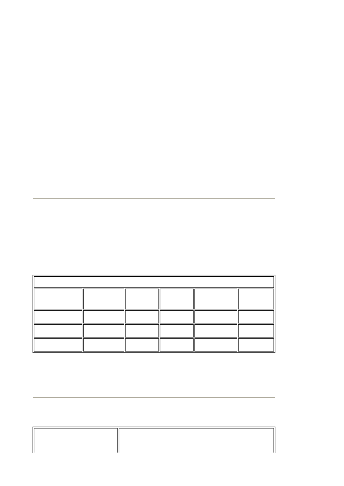
10 factory preset modes:
Resolution Mode H. freq (kHz) V. freq (Hz)
PC
640x350 VGA-1 31.469 70.086
640x480 VGA VESA 60 31.469 59.940
640x480 VGA VESA 75 37.500 75.000
720x400 IBM VGA 3H 31.468 70.087
800x600 SVGA VESA 56 35.156 56.250
800x600 SVGA VESA 60 37.879 60.317
800x600 SVGA VESA 75 46.875 75.000
1280x1024 XGA VESA 60 48.363 60.004
1280x1024 XGA VESA 75 60.023 75.029
1280x768 GTF 60 47.700 60.000
Page 3 of 8Product Information
RETURN TO TOP OF THE PAGE
Automatic Power Saving
If you have VESA DPMS compliance display card or software installed in your
PC, the monitor can automatically reduce its power consumption when not in
use. If an input from a keyboard, mouse or other input device is detected, the
monitor will then 'wake up' automatically. The following table shows the power
consumption and signaling of this automatic power saving feature:
RETURN TO TOP OF THE PAGE
Physical Specifications
1280x768 Wincomm 45.113 56.260
1360x768 VESA 47.700 60.000
Video
720x480 480i 15.734 59.940
720x576 576i 15.625 50.000
720x480 480p 31.470 60.000
720x576 576p 31.250 50.000
1280x720 720p 28.200 50.000
1280x720 720p 33.750 60.000
1920x1080 1080i 37.500 50.000
1920x1080 1080i 45.000 60.000
Power Management Definition
VESA
Mode Video H-sync V-
sync Power
Used LED
color
Active On Yes Yes 100 W (typ.) Blue
Sleep Off No No < 5 W Amber
Switch Off Off - - < 3 W Off
• Dimension (WxHxD) * 1014mm x 517mm x 244mm (incl. Pedestal,
Speakers)
Page 4 of 8Product Information
* This data is subject to change without notice.
RETURN TO TOP OF THE PAGE
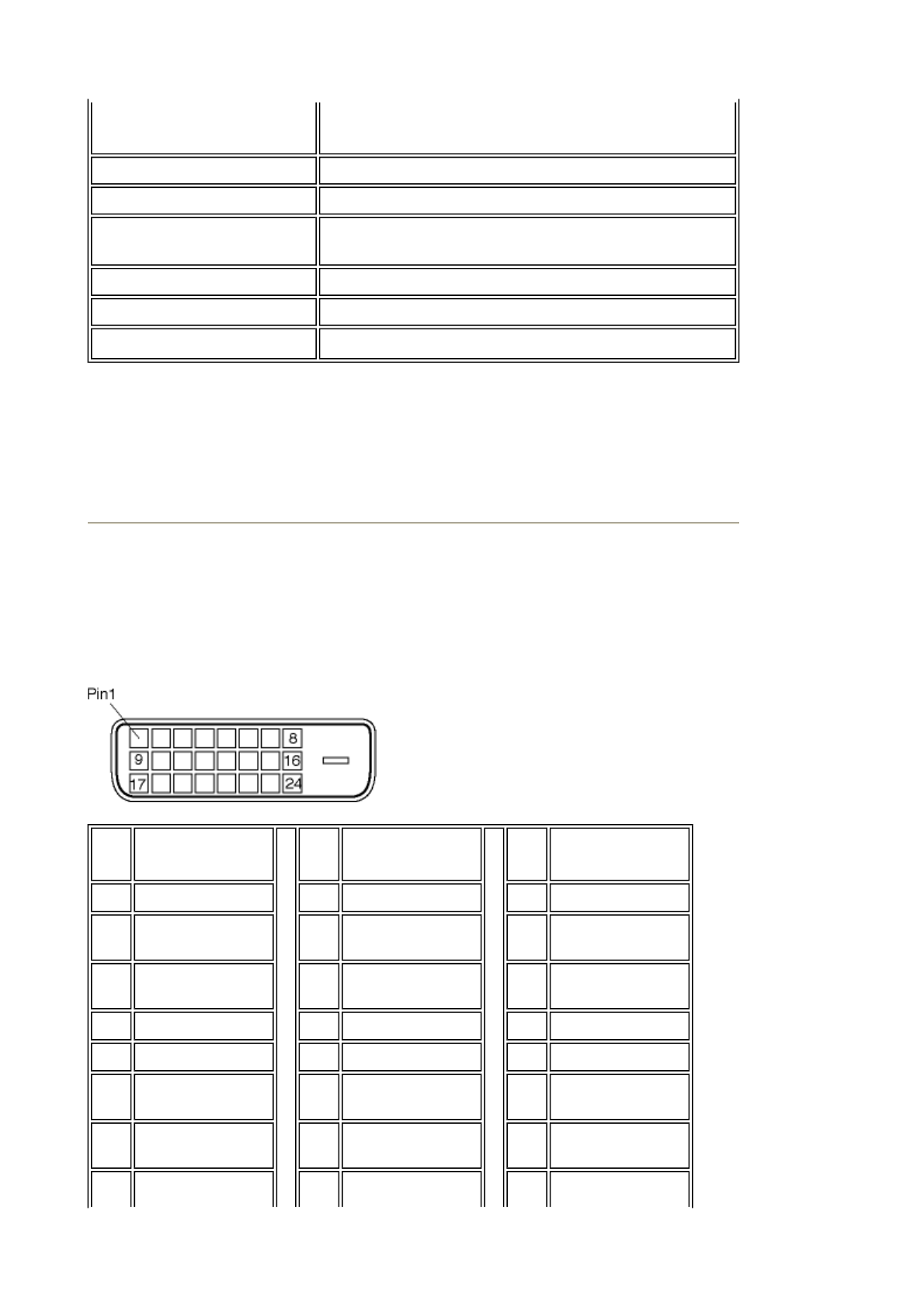
Pin Assignment
1. The digital only connector (DVI-D) contains 24 signal contacts organized in
three rows of eight contacts. Signal pin assignments are listed in the following
table:
794mm x 490mm x 130mm (w/o Pedestal,
Speakers)
• Weight 19.2 kg (incl. Pedestal, Speakers)
• Power supply 100 — 240 VAC, 60 — 50 Hz
• Power consumption PC Mode: 100 W (typ.)
TV Mode: 130 W (typ.)
• Temperature (operating) 5° C to 35° C
• Relative humidity 20% to 80%
• System MTBF 50K hrs (excluding CCFL 40Khrs)
Pin
No. Signal
Assignment
Pin
No. Signal
Assignment
Pin
No. Signal
Assignment
1 T.M.D.S. Data2- 9 T.M.D.S. Data1- 17 T.M.D.S. Data0-
2 T.M.D.S.
Data2+ 10 T.M.D.S.
Data1+ 18 T.M.D.S.
Data0+
3 T.M.D.S.
Data2/4 Shield 11 T.M.D.S.
Data1/3 Shield 19 T.M.D.S.
Data0/5 Shield
4 No connect 12 No connect 20 No connect
5 No connect 13 No connect 21 No connect
6 DDC Clock 14 +5V Power 22 T.M.D.S. Clock
Shield
7 DDC Data 15 Hot Plug Detect 23 T.M.D.S.
Clock+
Ground (for
Page 5 of 8Product Information
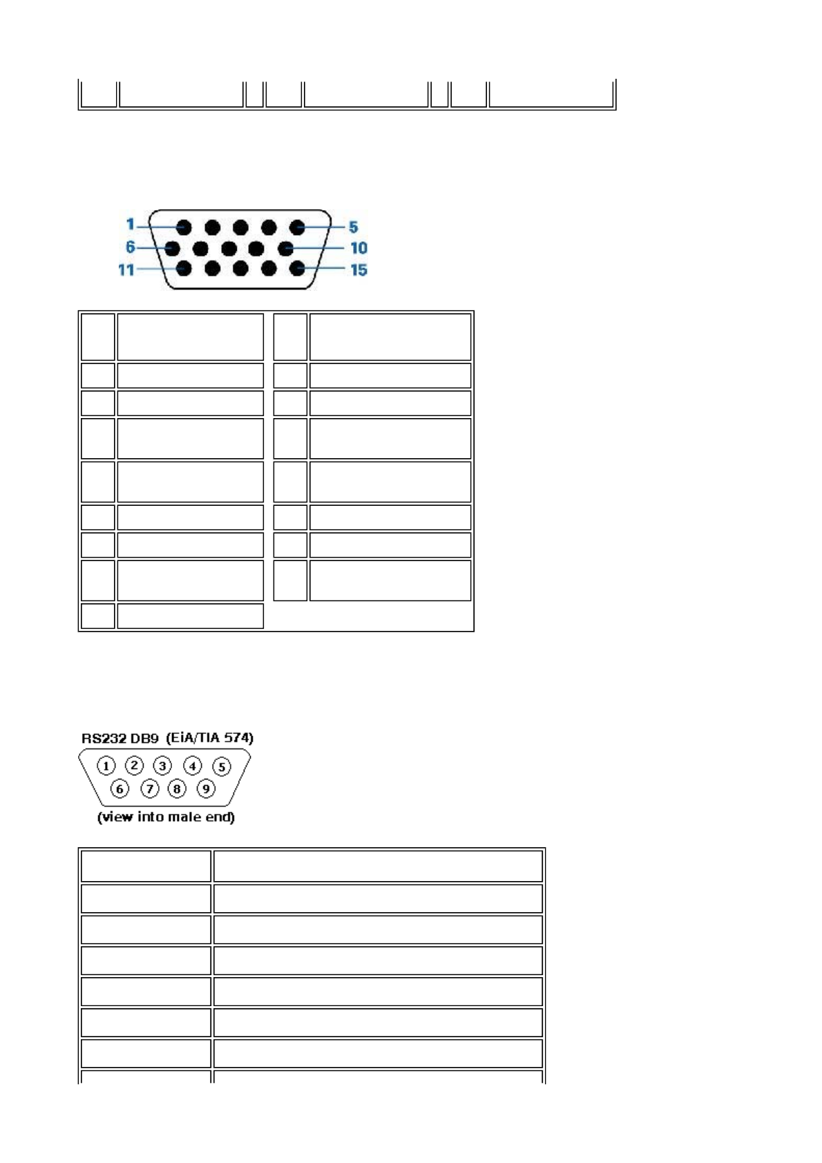
2. The 15-pin D-sub connector (male) of the signal cable:
3. RS232 Connector
D-sub 9-pin male connector for communication with plasma engine or PC.
8 No connect 16 +5V) 24 T.M.D.S. Clock-
Pin
No. Assignment Pin
No. Assignment
1 Red video input 9 DDC +5V
2 Green video input 10 Cable detect
3 Blue video input 11 Identical output,
connected to pin 10
4 Ground 12 Serial data line
(SDA)
5 NC 13 H. Sync / H+V
6 Red video ground 14 V. Sync
7 Green video
ground 15 Data clock line (SCL)
8 Blue video ground
Pin No. RS-232 (EIA-232-A) Function
3 Transmit Data (TD) from DTE to DCE
2 Receive Data (RD) from DCE to DTE
7 Request to Send (RTS)
8 Clear to Send (CTS)
6 DCE Ready (DSR)
5 Signal Ground (SG)
Page 6 of 8Product Information
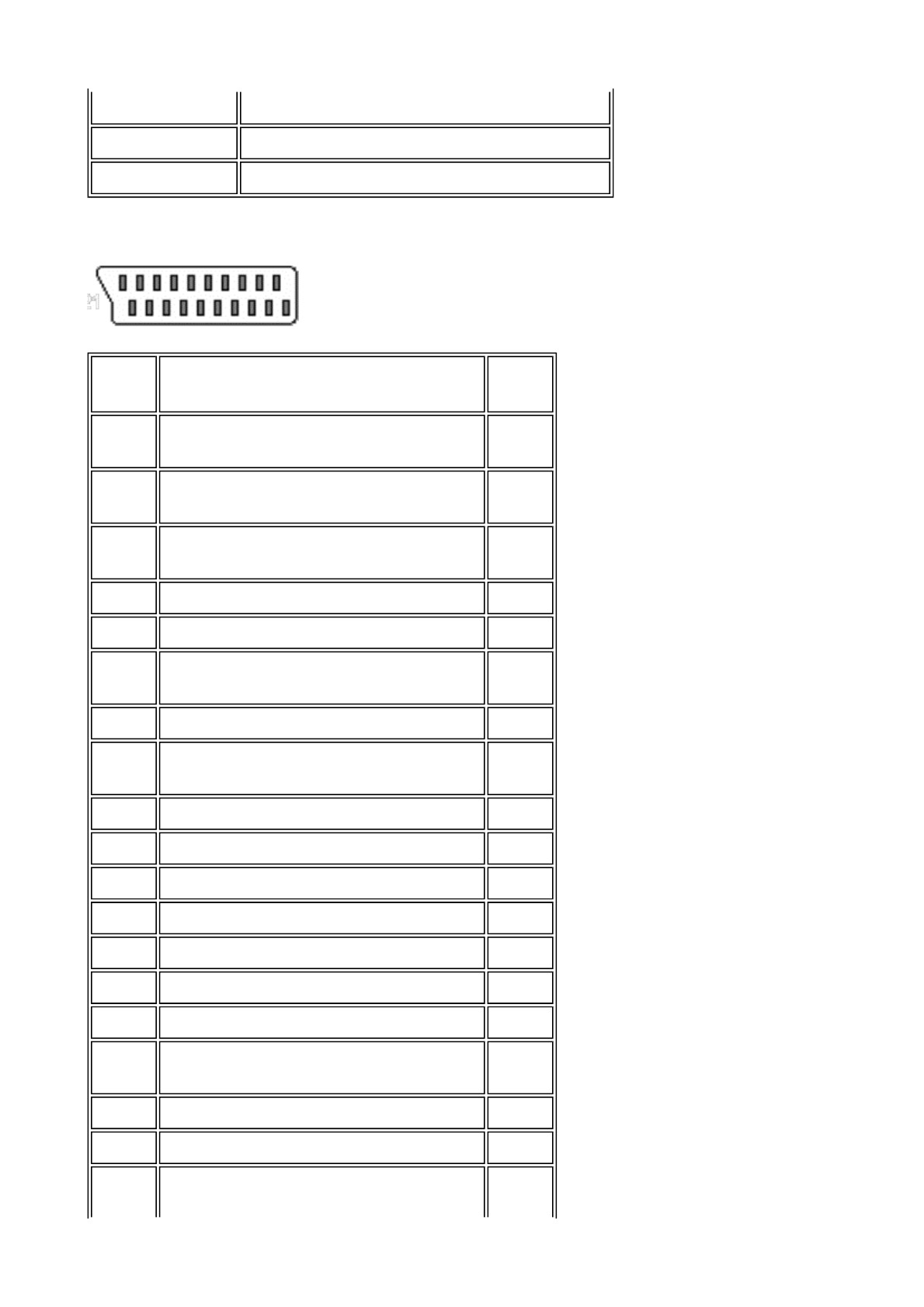
4. SCART Connector
1 Received Line Signal Detector (DCD)
4 DTE Ready (DTR)
9 Ring Indicator
Pin
No. Signal Pin
No.
1 Audio right channel output (0.5 Vrms,
< 1K ohms) 2
2 Audio right channel input (0.5 Vrms, >
10K ohms) 1
3 Audio left channel output (0.5 Vrms, <
1K ohms) 6
4 Audio ground 4
5 Blue signal ground 5
6 Audio left channel input (0.5 Vrms, >
10K ohms) 3
7 Blue signal I/O (0.7 Vp-p, 75 ohms) 7
8 Function switching I/O (L: < 2V, H: >
10V, 10K ohms) 8
9 Green signal ground 9
10 Intercommunication data line No. 1 10
11 Green signal I/O (0.7 Vp-p, 75 ohms) 11
12 Intercommunication data line No. 2 12
13 Red signal ground 13
14 Blanking signal ground 14
15 Red signal I/O (0.7 Vp-p, 75 ohms) 15
16 Blanking signal I/O (L: < 0.4V, H:
>1.0V, 75 ohms) 16
17 Composite video signal ground 18
18 Blanking signal ground 17
19 Composite video signal output (1 Vp- 20
Page 7 of 8Product Information

RETURN TO TOP OF THE PAGE
Product Views
Follow the links to see various views of the monitor and its components.
Product Description
RETURN TO TOP OF THE PAGE
p, 75 ohms, sync: negative)
20 Composite video signal input (1 Vp-p,
75 ohms, sync: negative) 19
21 Plug shield (common ground) 21
Page 8 of 8Product Information
Installing your LCD Monitor/TV
Product Description • Connecting to Your PC, TV antenna, DVD/VCR etc. •
Getting Started • Optimizing Performance
Product Description
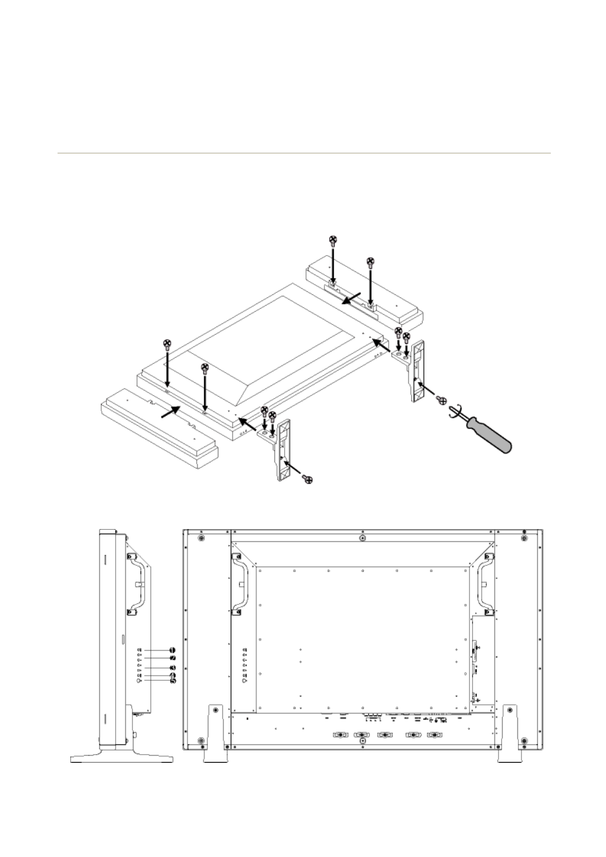
Installing your LCD Monitor/TV
Side View (Left)
Page 1 of 4Installing your LCD Monitor/TV
RETURN TO TOP OF THE PAGE
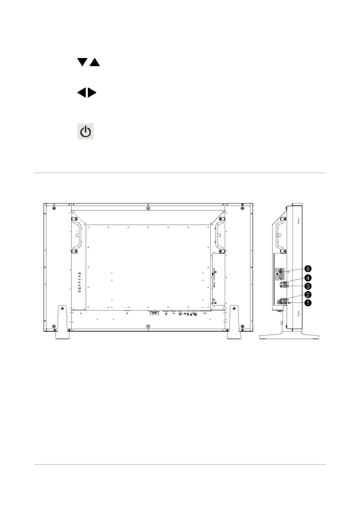
Side View (Right)
RETURN TO TOP OF THE PAGE
1 INPUT Selecting input source
2
Increase or decrease the channel number
or
moving up or down to highlight the function in OSD
3
Increase or decrease the level of audio volume
or
moving left or right to highlight the sub-menu in the
selected function of OSD
4 MENU Open the OSD or confirm the selected function
5 DC power switch On/Off
1 Audio input for composite input Audio (left and right) in put for compo
site signal in put.
2 Composite input Composite (CVBS) signal input
3 S-Video input S-Video signal input
4 Earphone output Earphone output
5 TV tuner TV tuner input (available in TV
version only)
Page 2 of 4Installing your LCD Monitor/TV
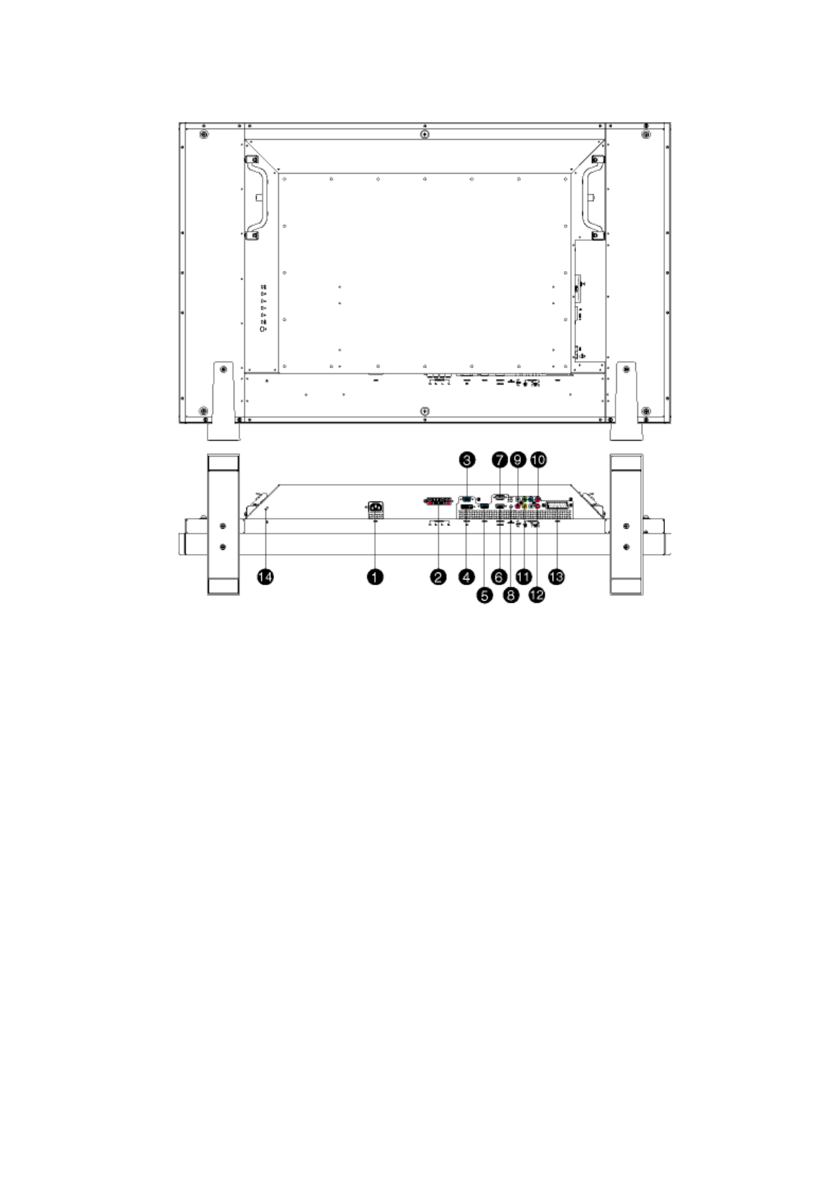
Rear View
1 AC in AC power in
2 Speakers output External speakers output
3 D-Sub output PC analog D-Sub output
4 DVI-D input PC digital input
5 D-Sub input PC analog D-Sub input
6 RS232 input RS232 network connection Input
7 RS232 output RS232 network connection output
for the use of loop through
function
8 PC audio PC stereo audio input
9 Audio input for component signal Audio (left and right) input for
component signal input
10 Component input Component (YPbPr ) signal input
11 Composite output Composite (CVBS) output for the
use of loop through function
12 Audio output for composite
output Audio (left and right) out put for
compo site signal out put.
13 External / EURO-AV SCART connection (for the use of
European model only)
Page 3 of 4Installing your LCD Monitor/TV

Optimising Performance
zFor best performance, ensure that your display settings are set at 1360x768, 60Hz.
zYou can also install the Flat Panel Adjust (FP Adjust) program, a program for getting
the best performance out of your monitor. This is included on this CD. Step-by-step
instructions are provided to guide you through the installation process. Click on the lin
to find out more about this program.
More about FP_setup04.exe
RETURN TO TOP OF THE PAGE
14 Kensington lock Kensington lock
Note: You can check the current display settings by pressing the
'MENU' button once.
Page 4 of 4Installing your LCD Monitor/TV
Federal Communications Commission (FCC) Notice (U.S. Only)
zReorient or relocate the receiving antenna.
zIncrease the separation between the equipment and receiver.
zConnect the equipment into an outlet on a circuit different from that to
which the receiver is connected.
zConsult the dealer or an experienced radio/TV technician for help.
Use only RF shielded cable that was supplied with the monitor when connecting
this monitor to a computer device.
To prevent damage which may result in fire or shock hazard, do not expose this
appliance to rain or excessive moisture.
THIS CLASS B DIGITAL APPARATUS MEETS ALL REQUIREMENTS OF THE
CANADIAN INTERFERENCE-CAUSING EQUIPMENT REGULATIONS.
RETURN TO TOP OF THE PAGE
Commission Federale de la Communication (FCC Declaration)
This equipment has been tested and found to comply with the limits
for a Class B digital device, pursuant to Part 15 of the FCC Rules.
These limits are designed to provide reasonable protection against
harmful interference in a residential installation. This equipment
generates, uses and can radiate radio frequency energy and, if not
installed and used in accordance with the instructions, may cause
harmful interference to radio communications. However, there is no
guarantee that interference will not occur in a particular installation.
If this equipment does cause harmful interference to radio or
television reception, which can be determined by turning the
equipment off and on, the user is encouraged to try to correct the
interference by one or more of the following measures:
Changes or modifications not expressly approved by the party
responsible for compliance could void the user's authority to operate
the equipment.
Cet équipement a été testé et déclaré conforme auxlimites des
appareils numériques de class B,aux termes de l'article 15 Des
règles de la FCC. Ces limites sont conçues de façon à fourir une
protection raisonnable contre les interférences nuisibles dans le
cadre d'une installation résidentielle. CET appareil produit, utilise et
peut émettre des hyperfréquences qui, si l'appareil n'est pas installé
et utilisé selon les consignes données, peuvent causer des
Page 1 of 2Regulatory Information

zRéorienter ou déplacer l'antenne de réception.
zAugmenter la distance entre l'équipement et le récepteur.
zBrancher l'équipement sur un autre circuit que celui utilisé par le récepteur.
zDemander l'aide du marchand ou d'un technicien chevronné en
radio/télévision.
N'utiliser que des câbles RF armés pour les connections avec des ordinateurs
ou périphériques.
CET APPAREIL NUMERIQUE DE LA CLASSE B RESPECTE TOUTES LES
EXIGENCES DU REGLEMENT SUR LE MATERIEL BROUILLEUR DU
CANADA.
RETURN TO TOP OF THE PAGE
interférences nuisibles aux communications radio. Cependant, rien
ne peut garantir l'absence d'interférences dans le cadre d'une
installation particulière. Si cet appareil est la cause d'interférences
nuisibles pour la réception des signaux de radio ou de télévision, ce
qui peut être décelé en fermant l'équipement, puis en le remettant
en fonction, l'utilisateur pourrait essayer de corriger la situation en
prenant les mesures suivantes:
Toutes modifications n'ayant pas reçu l'approbation des services
compétents en matière de conformité est susceptible d'interdire à
l'utilisateur l'usage du présent équipement.
Page 2 of 2Regulatory Information