Philips Group Innovation Research 0031357 Philips Wi-Fi reference design User Manual Product Requirements Specification
Philips Group Innovation, Research Philips Wi-Fi reference design Product Requirements Specification
UserManual.wiki
>
Philips Group Innovation Research
>
0031357 User Manual
UserManual
Navigation menu
Upload a User Manual
Namespaces
Wiki Guide
HTML
PDF
Info
Views
User Manual
Discussion / Help
Navigation
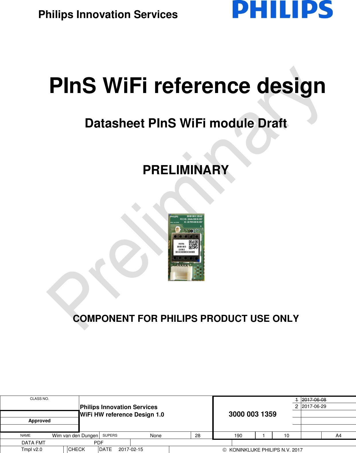

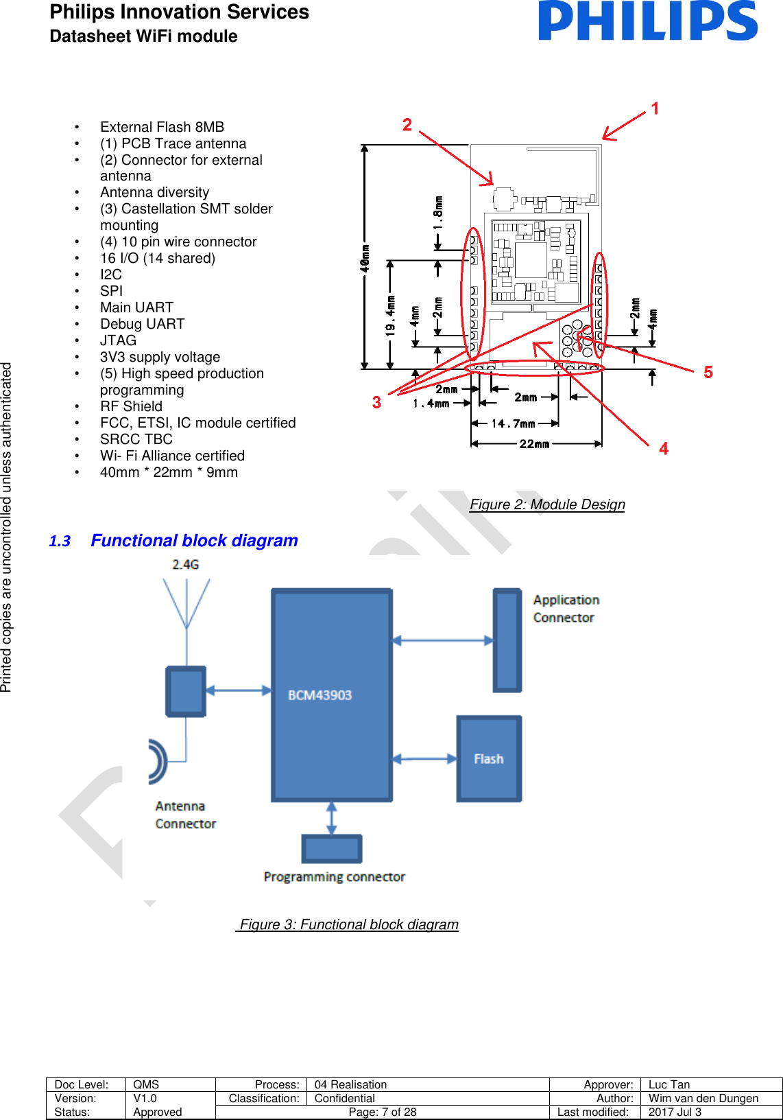
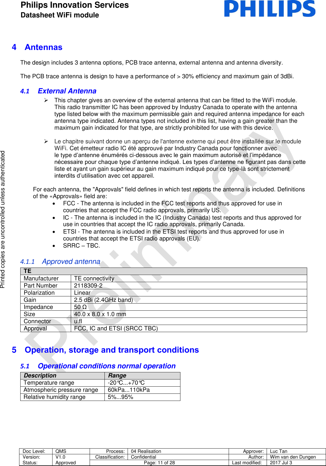
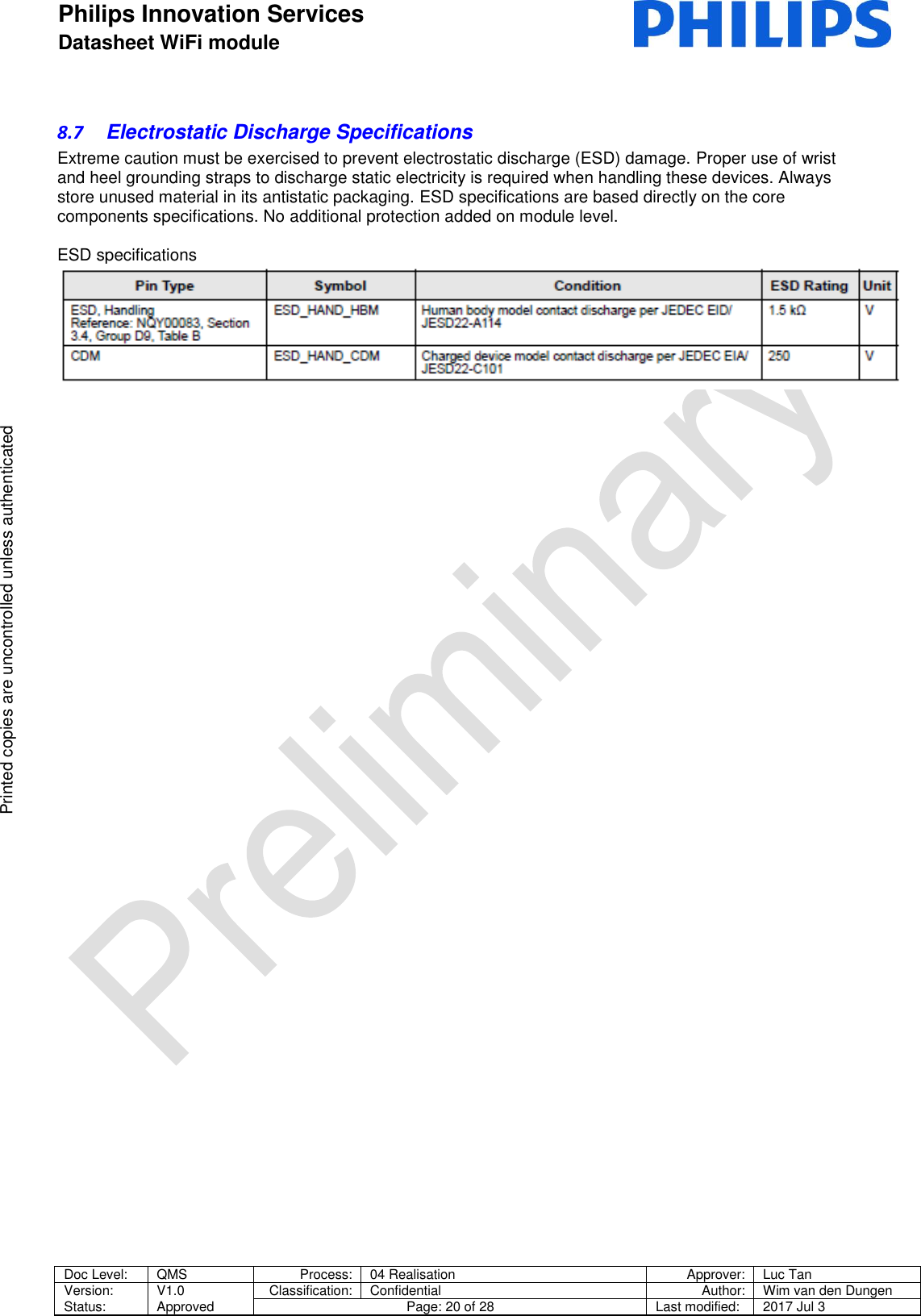
![Philips Innovation Services Datasheet WiFi module Doc Level: QMS Process: 04 Realisation Approver: Luc Tan Version: Status: V1.0 Approved Classification: Confidential Author: Wim van den Dungen Page: 5 of 28 Last modified: 2017 Jul 3 Printed copies are uncontrolled unless authenticated Printed copies are uncontrolled unless authenticated 1 Introduction 1.1 Introduction PInS WiFi module V1.0 is a PCB Wi-Fi module designed by Philips innovation services (PInS) and based on the latest Cypress WiFI SoC. The design is based on an internal Philips study and is backwards compatible with an already used Philips module called Philips YD (obsolete), Additional functionality is added to optimize usability and a cost effective solution of adding connectivity to Philips products. The design is aligned with Philips CDPP, PSSO, PInS, and multiple business and making fast and easy integration possible. See datasheet of CYW43903 WICED™™ IEEE 802.11 a/b/g/n SoC with an Embedded Applications Processor [1] for detailed specifications. General description of the CYW43903 SoC that forms the bases of the module reference design: The Cypress CYW43903 embedded wireless system-on-a-chip (SoC) is uniquely suited for Internet-of-Things applications. It is IEEE 802.11n compliant and provides full IEEE 802.11 b/g legacy compatibility with enhanced performance. The device includes an ARM Cortex-based applications processor, a single stream IEEE 802.11n MAC/baseband/radio, a power amplifier (PA), and a receive low-noise amplifier (LNA). It also supports optional antenna diversity for improved RF performance in difficult environments. The CYW43903 is an optimized SoC targeting embedded Internet-of-Things applications in the industrial and medical sensor, home appliance markets. Using advanced design techniques and process technology to reduce active and idle power, the device is designed for embedded applications that require minimal power consumption and a compact size. The device includes a PMU for simplifying system power topology and allows for direct operation from a battery while maximizing battery life. Figure 1: Block Diagram](https://usermanual.wiki/Philips-Group-Innovation-Research/0031357/User-Guide-3509825-Page-5.png)
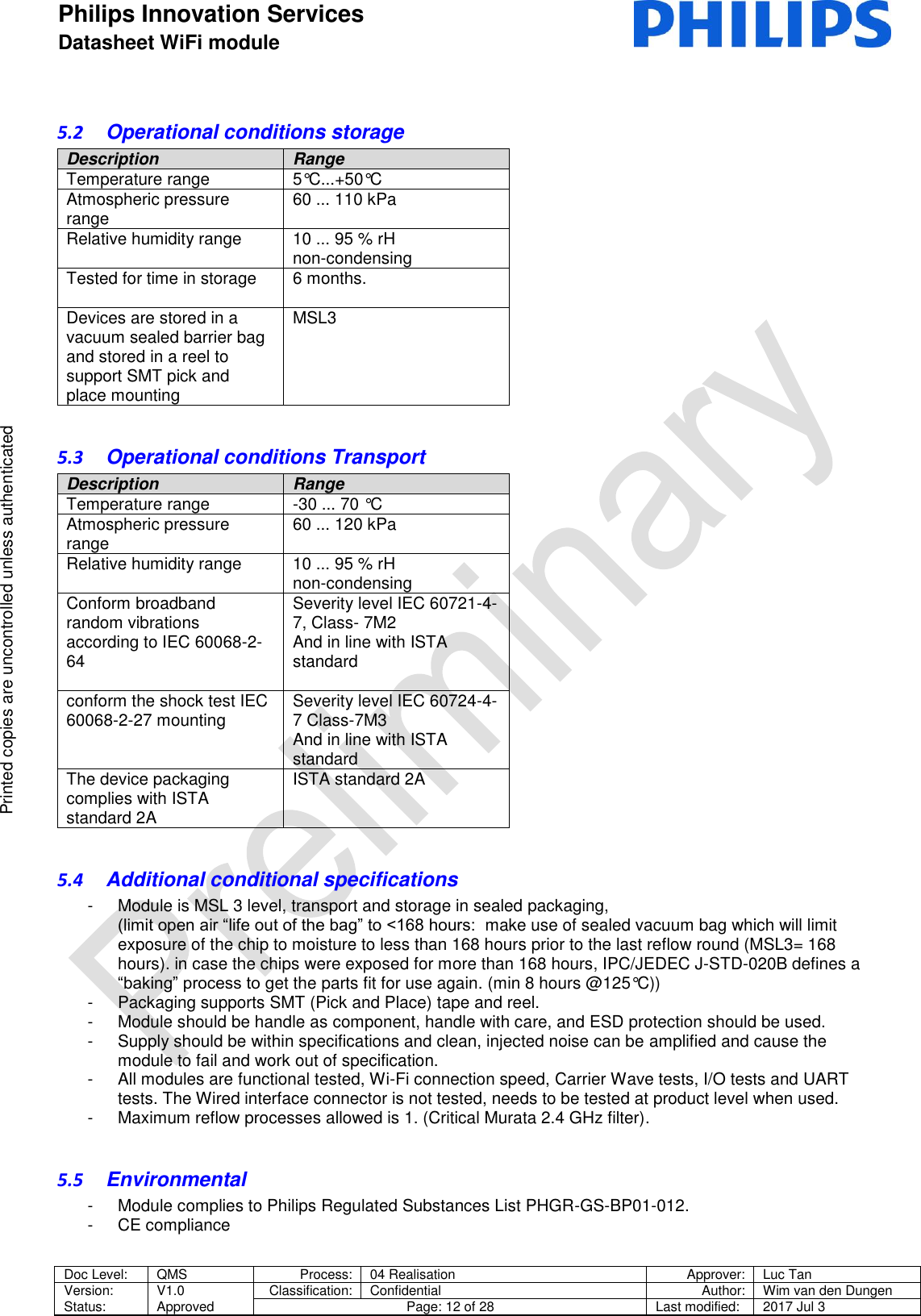
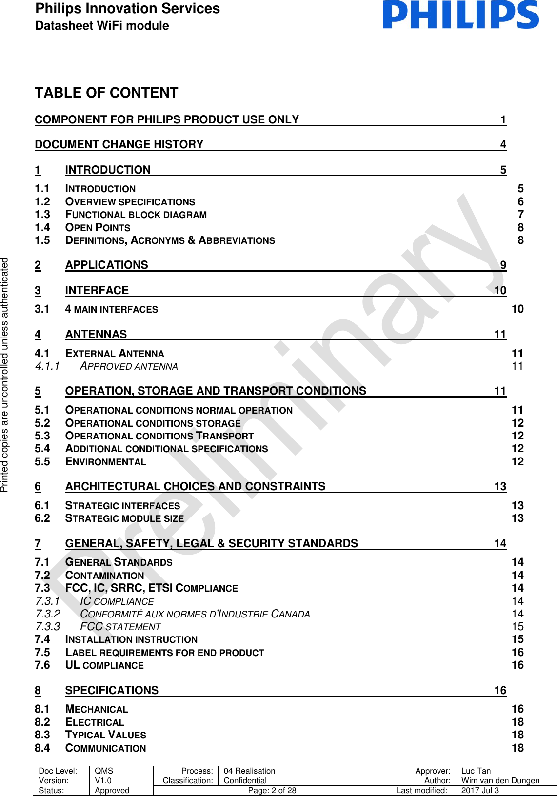
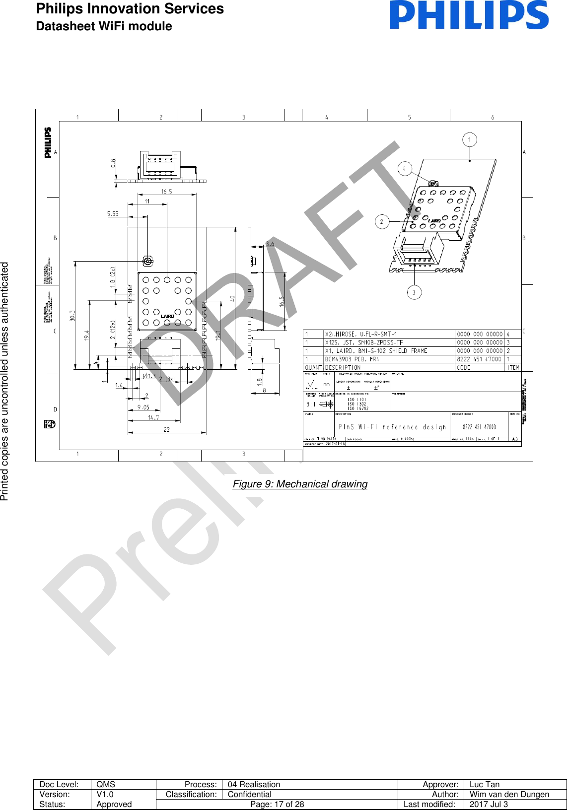
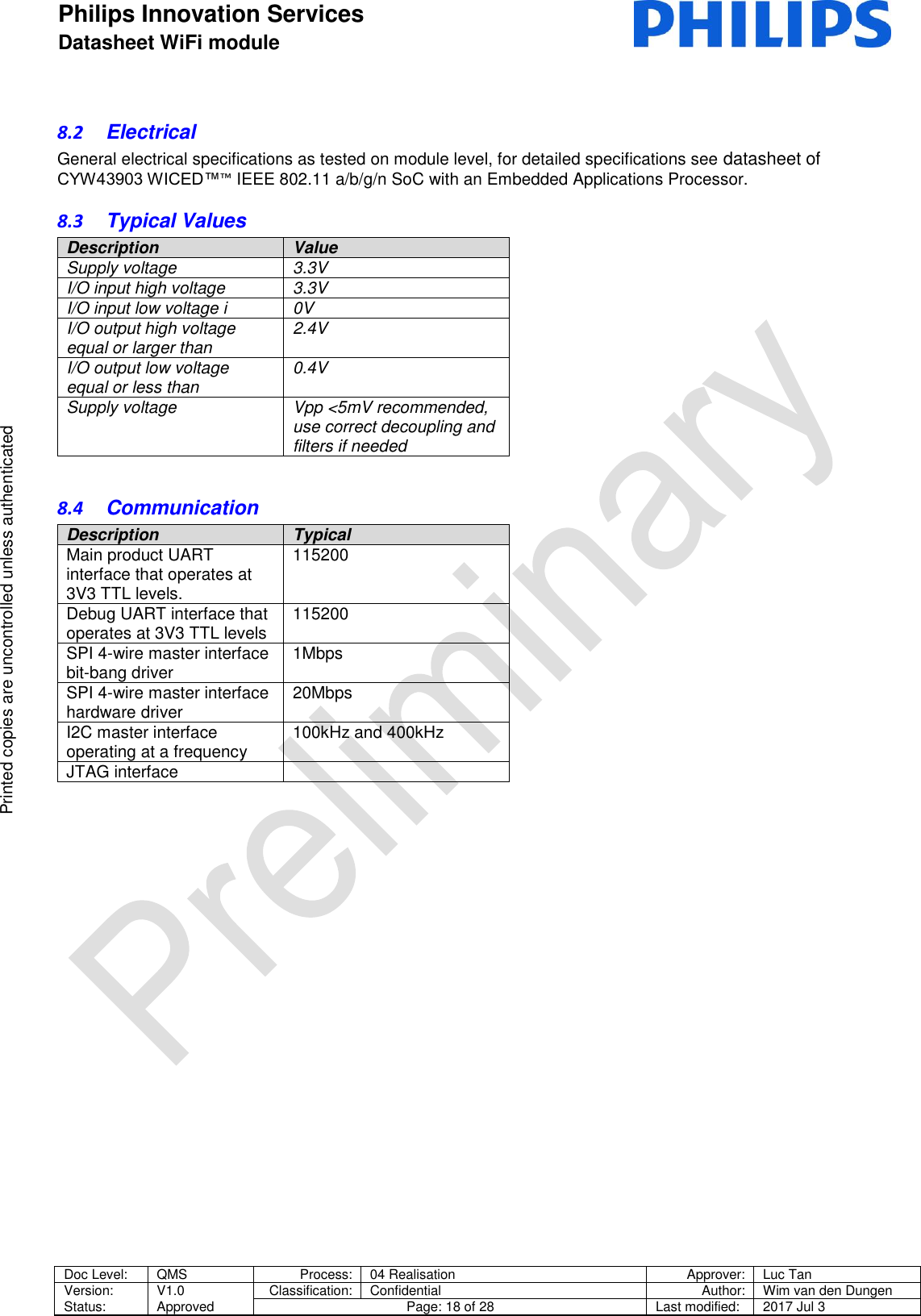
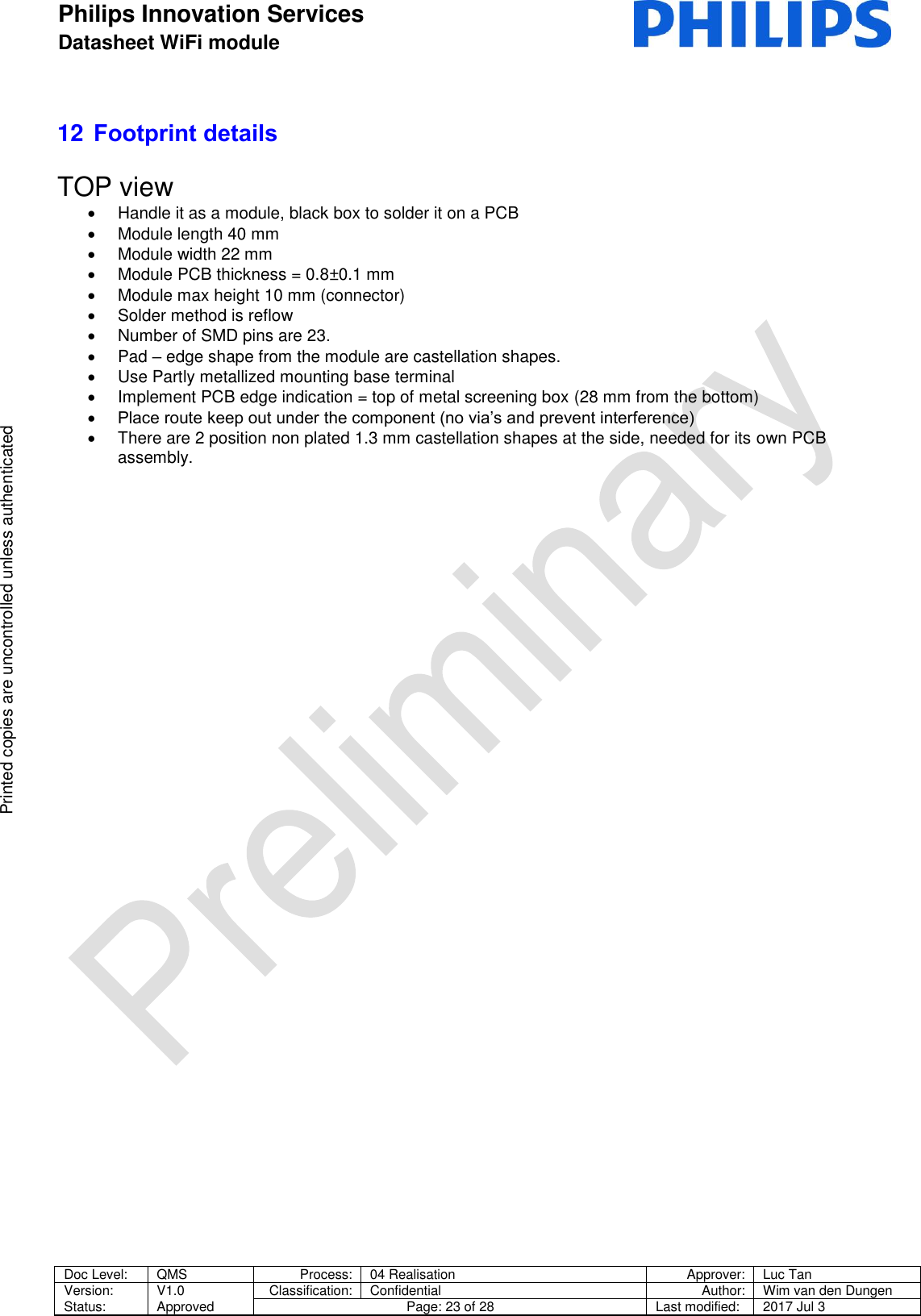
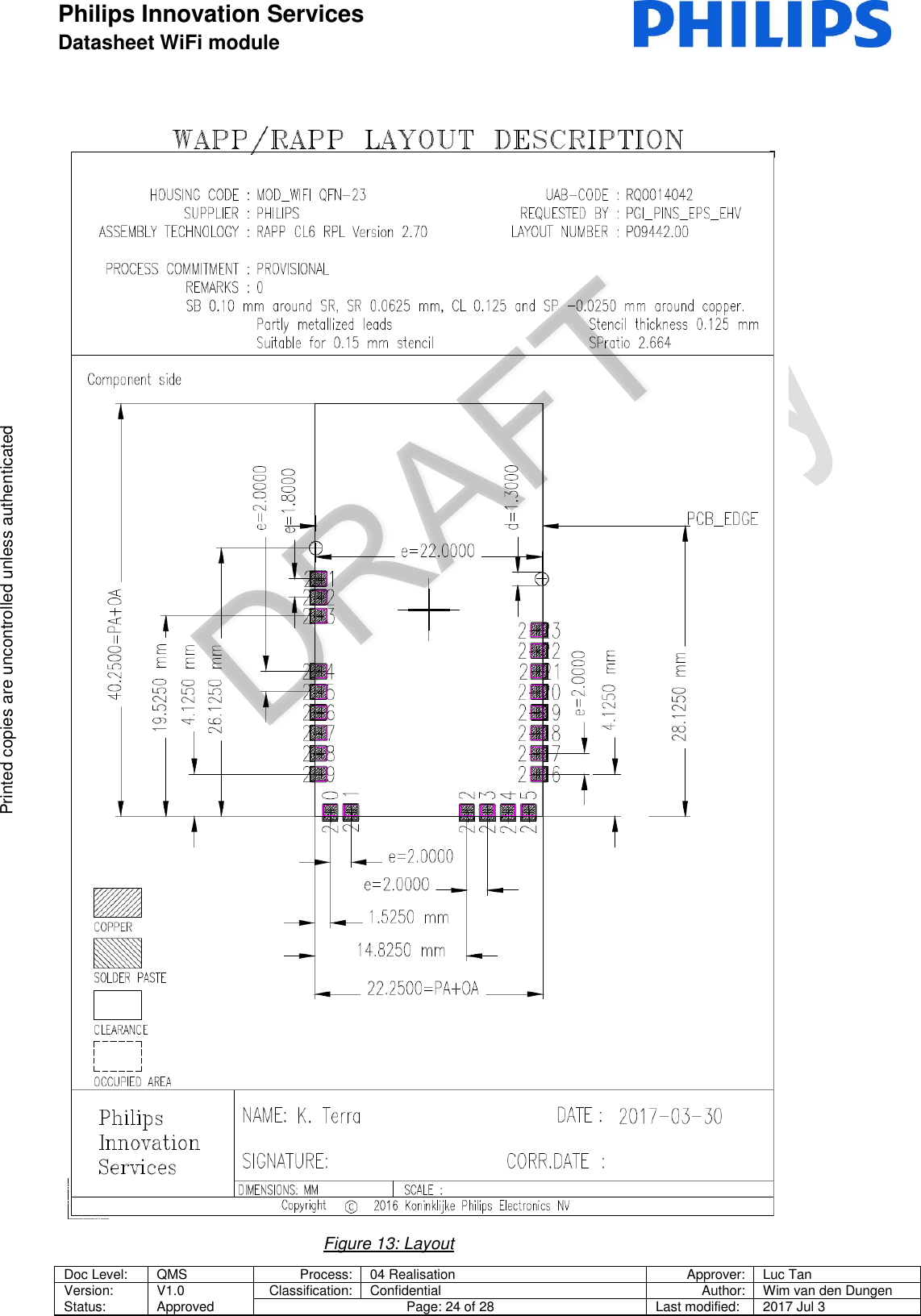
![Philips Innovation Services Datasheet WiFi module Doc Level: QMS Process: 04 Realisation Approver: Luc Tan Version: Status: V1.0 Approved Classification: Confidential Author: Wim van den Dungen Page: 16 of 28 Last modified: 2017 Jul 3 Printed copies are uncontrolled unless authenticated Printed copies are uncontrolled unless authenticated e.g Radiofrequency radiation exposure Information: This equipment complies with FCC radiation exposure limits set forth for an uncontrolled environment. This equipment should be installed and operated with minimum distance of 20 cm between the radiator and your body. This transmitter must not be co-located or operating in conjunction with any other antenna or transmitter. Cet équipement est conforme aux limites d'exposition aux rayonnements IC établies pour un environnement non contrôlé. Cet équipement doit être installé et utilisé avec un minimum de 20 cm de distance entre la source de rayonnement et votre corps. The antenna of the module may not be removed, replaced nor modified. The antenna must not be co-located or operating in conjunction with any other antenna or transmitter. No additional antenna must be used. When the final host product operating with this transmitter deviate from above, installation of this module into specific final hosts may require the submission of a Class II permissive change application containing data pertinent to RF Exposure, spurious emissions, ERP/EIRP, and host/module authentication, or new application if appropriate. 7.5 Label requirements for end product For an end product using the PInS WiFI module there must be a label containing, at least, the following information: The label must be affixed on an exterior surface of the end product such that it will be visible upon inspection in compliance with the modular approval guidelines developed by the FCC. In accordance with 47 CFR § 15.19, the end product shall bear the following statement in a conspicuous location on the device: "This device complies with Part 15 of the FCC Rules. Operation is subject to the following two conditions; (1) This device may not cause harmful interference, and (2) This device must accept any interference received, including interference that may cause undesired operation." 7.6 UL compliance UL94V-0 compliance on PCB level. 8 Specifications 8.1 Mechanical The dimensions and footprint are part of the platform and are considered strategic to have a common base. Supporting backwards compatibility and future extensions of the platform proposition. The main dimensions are 40mm * 22mm (+/- 0.250mm) and a maximum height of <9mm. Refer to the latest sheet 110 [3] of the PCB for more information about the mechanical drawings. This device contains FCC ID: 2AALC0031357 IC ID: 22799-0031357 CMIIT ID: TBC](https://usermanual.wiki/Philips-Group-Innovation-Research/0031357/User-Guide-3509825-Page-16.png)
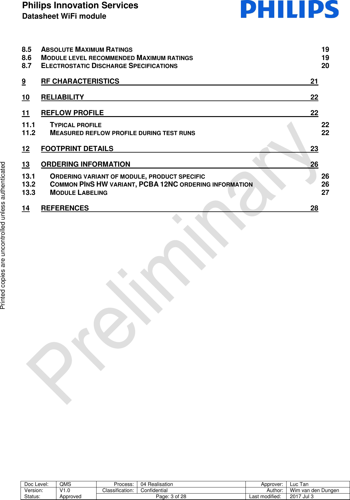
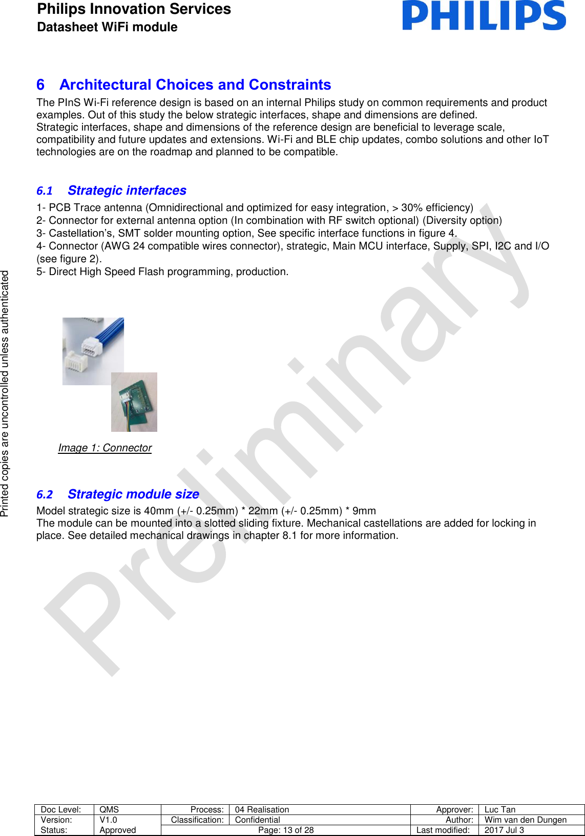
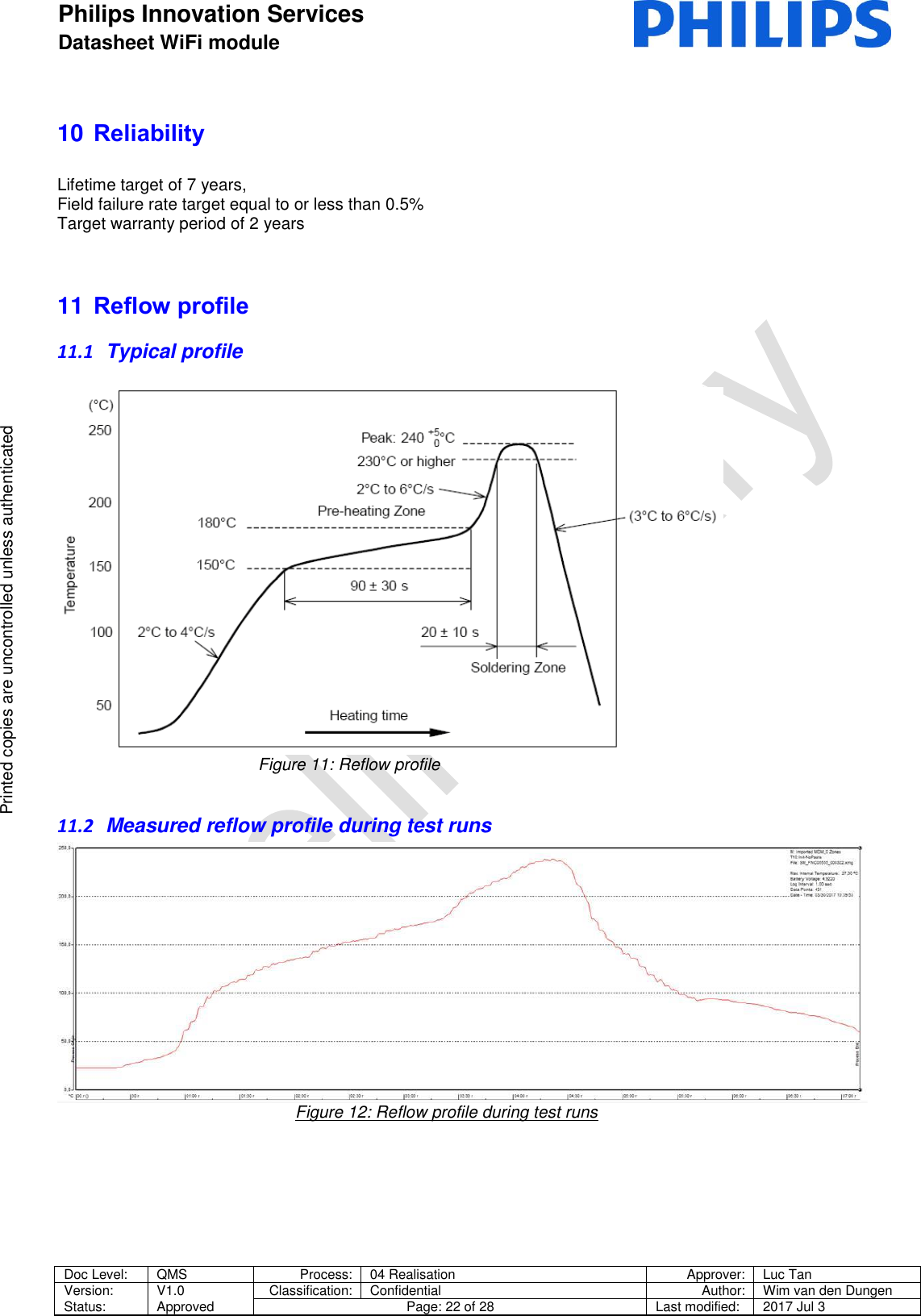
![Philips Innovation Services Datasheet WiFi module Doc Level: QMS Process: 04 Realisation Approver: Luc Tan Version: Status: V1.0 Approved Classification: Confidential Author: Wim van den Dungen Page: 21 of 28 Last modified: 2017 Jul 3 Printed copies are uncontrolled unless authenticated Printed copies are uncontrolled unless authenticated 9 RF characteristics Also see datasheet of CYW43903 WICED™™ IEEE 802.11 a/b/g/n SoC with an Embedded Applications Processor. Description Range Closed-loop TX power variation at highest power level stetting. Across full temperature and voltage range. Applies to 10dBm to 20dB output power range Max +/- 1.5dB See [1] for actual value See datasheet CYW43903 WICED™ IEEE 802.11 a/b/g/n SoC with an Embedded Applications Processor [1] for additional information.](https://usermanual.wiki/Philips-Group-Innovation-Research/0031357/User-Guide-3509825-Page-21.png)
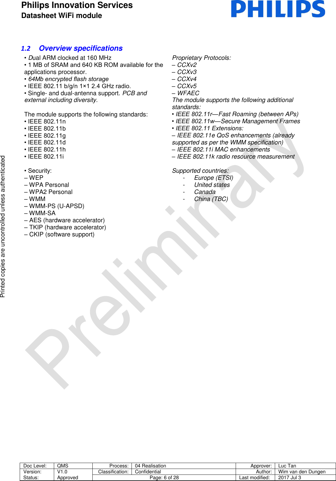
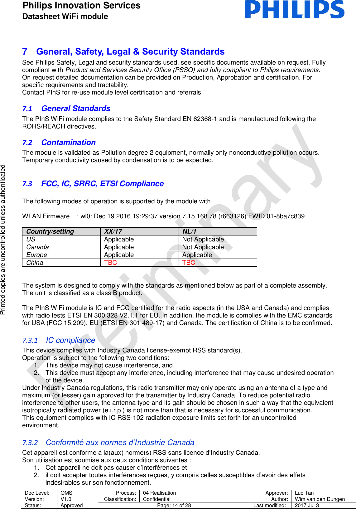
![Philips Innovation Services Datasheet WiFi module Doc Level: QMS Process: 04 Realisation Approver: Luc Tan Version: Status: V1.0 Approved Classification: Confidential Author: Wim van den Dungen Page: 28 of 28 Last modified: 2017 Jul 3 Printed copies are uncontrolled unless authenticated Printed copies are uncontrolled unless authenticated QR CODE LABEL INFORMATION CODE INFORMATION YY YEAR WW WEEK D (PRODUCTION DAY) H: MONDAY I: TUESDAY J: WEDNESDAY K: THURSDAY L: FRIDAY M: SATURDAY N: SUNDAY MAC Address (12 digit) XXXXXXXXXXXX Model 12NC (12 digit) XXXXXXXXXXXX 14 References Ref.# Document Title Document ID [1] CYW43903 WICED™™ IEEE 802.11 a/b/g/n SoC with an Embedded Applications Processor Datasheet 002-14826 Rev. *C [2] Integration manual PInS Wi-Fi module V0.1 N/A [3] 3000_003_13xxx_110_2017xxxx_WIFI_MECH N/A](https://usermanual.wiki/Philips-Group-Innovation-Research/0031357/User-Guide-3509825-Page-28.png)