Philips Group Innovation Research DTI2 DTI-2 User Manual for DTI 2
Philips Group Innovation, Research DTI-2 for DTI 2
UserManual.pdf

© 2013 Koninklijke Philips Electronics N.V.
All rights reserved.
DTI_2_UM_V2.0 8122 357 24302
2 EN
DTI-2
__________________________ __________________________
EN User manual NL Gebruiksaanwijzing
DE Benutzerhandbuch FR Mode d’emploi
SV Användarhandbok SR Korisničko uputstvo

EN 3
Contents
1 Important
Important Safety Instructions 4
Notice 4
Recycling 5
2 Your Discreet Tension Indicator 5
Introduction 5
What’s in the box 6
Overview of the device 6
User interface 7
3 Intended use 7
4 How to use the device 8
Wearing instructions
Switching the device on/off 8
Bluetooth wireless data transmission 9
Event marker 9
Status button 9
Time synchronization 9
Battery charging 10
Data readout 10
Data format and visualization 10
5 Product information 12
4 EN
1 Important
Important Safety Instructions
1 Read these instructions.
2 Keep these instructions.
3 Heed all warnings.
4 Follow all instructions.
5 Do not use this device under shower/in bath.
6 Clean only with dry or moist cloth.
7 Only use attachments/accessories specified by the manufacturer.
8 Refer all servicing to qualified service personnel. Servicing is
required when the device has been damaged in any way, such as
when the device has been exposed to water, does not operate
normally, or has been dropped
9 Battery usage CAUTION – To prevent battery leakage which may
result in bodily injury, property damage, or damage to the unit, the
batteries (battery pack or batteries installed) shall not be exposed
to excessive heat such as sunshine, fire or the like.
Notice
Any changes or modifications made to this device that are not
expressively approved by Philips may void the user’s authority to operate
the equipment.
This is a class 1 device.
Hereby Philips Research declares that this skin conductance wristband is
in compliance with the essential requirements and other relevant
provisions of Directive 1999/5/EC.
This product complies with the radio interference requirements of the
European Community.
0682
EN 5
This device complies with Part 15 of the FCC Rules.
Operation is subject to the following two conditions:
(1) this device my not cause harmful interference, and
(2) this device must accept any interference received, including
interference that may cause undesired operation.
NOTICE:
Changes or modifications made to this equipment not expressly
approved by PHILIPS may void the FCC authorization to operate this
equipment.
NOTE: This equipment has been tested and found to comply with the
limits for a Class B digital device, pursuant to Part 15 of the FCC Rules.
These limits are designed to provide reasonable protection against
harmful interference in a residential installation. This equipment
generates, uses and can radiate radio frequency energy and, if not
installed and used in accordance with the instructions, may cause
harmful interference to radio communications. However, there is no
guarantee that interference will not occur in a particular installation. If
this equipment does cause harmful interference to radio or television
reception, which can be determined by turning the equipment off and on,
the user is encouraged to try to correct the interference by one or more of
the following measures:
Reorient or relocate the receiving antenna.
Increase the separation between the equipment and receiver.
Connect the equipment into an outlet on a circuit different from that
to which the receiver is connected.
Consult the dealer or an experienced radio/TV technician for help.
Radiofrequency radiation exposure Information:
The radiated output power of the device is far below the FCC radio
frequency exposure limits. Nevertheless, the device shall be used in such
a manner that the potential for human contact during normal operation is
minimized.
6 EN
Recycling
Your product is designed and manufactured with high quality materials
and components, which can be recycled and reused.
When you see the crossed-out wheel bin symbol attached to a product, it
means the product is covered by the European Directive 2002/96/EC.
Never dispose of your product with other household waste. Please inform
yourself about the local rules on the separate collection of electrical and
electronic products. The correct disposal of your old product helps
prevent potentially negative consequences on the environment and
human health.
Your product contains batteries covered by the European Directive
2006/66/EC, which cannot be disposed of with normal household waste.
Please inform yourself about the local rules on separate collection of
batteries. The correct disposal of batteries helps prevent potentially
negative consequences on the environment and human health.
Always bring your product to a professional to remove the built-in battery.
2 Your Discreet Tension Indicator
Congratulations on your purchase and welcome to Philips!
Introduction
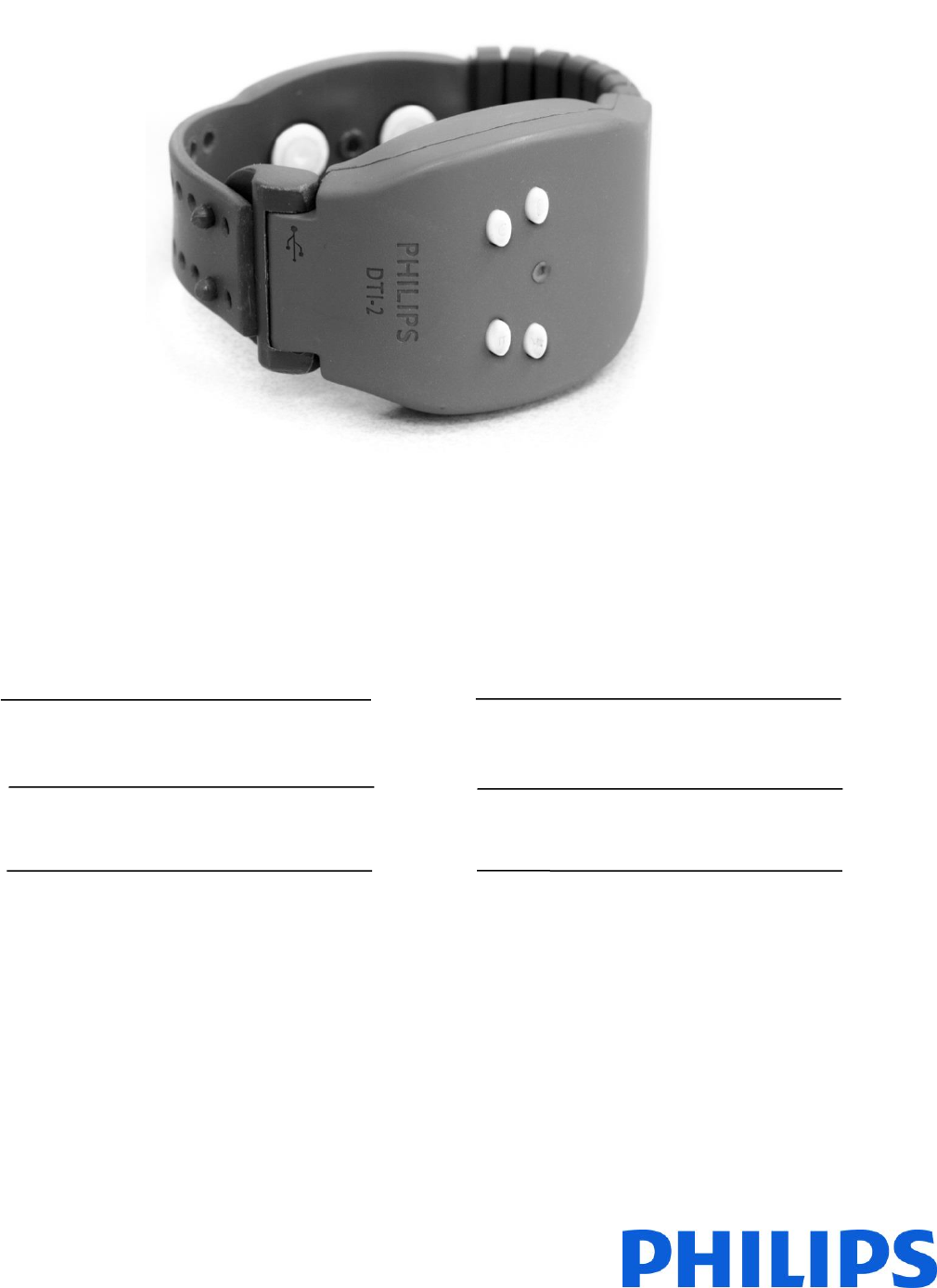
The Discreet Tension Indicator (DTI-2) is a wrist worn sensor device for
daily life use.
EN 7
What’s in the box
Check and identify the contents of your package:
1 x Sensor wristband
1 x USB cable
1 x USB charger
1 x quick start guide
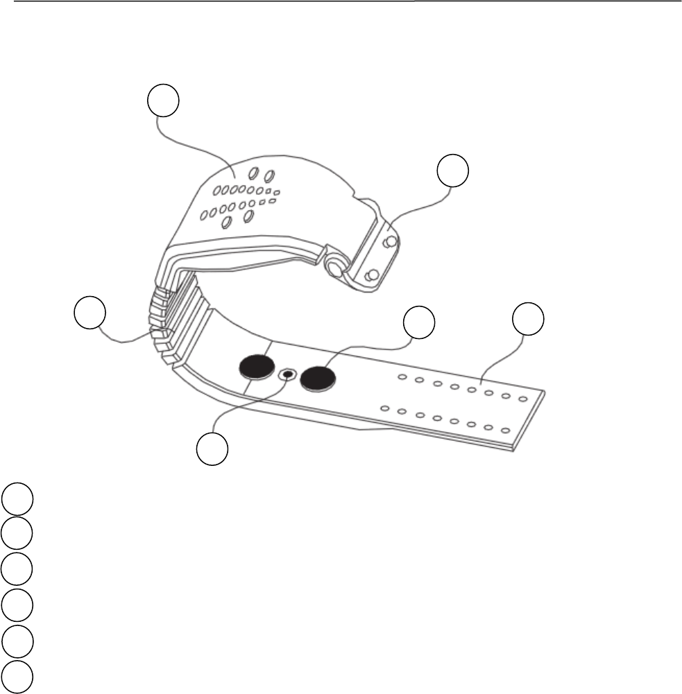
Overview of the device
1 User interface
2 Fastening hinge – the USB connector is behind it
3 Skin conductance electrode
4 Wrist strap
5 Skin temperature sensor
6 Personal fit segments
XXS 5 segments L 9 segments
XS 6 segments XL 10 segments
S 7 segments XXL 11 segments
M 8 segments
1
2
3
5
6
4
8 EN
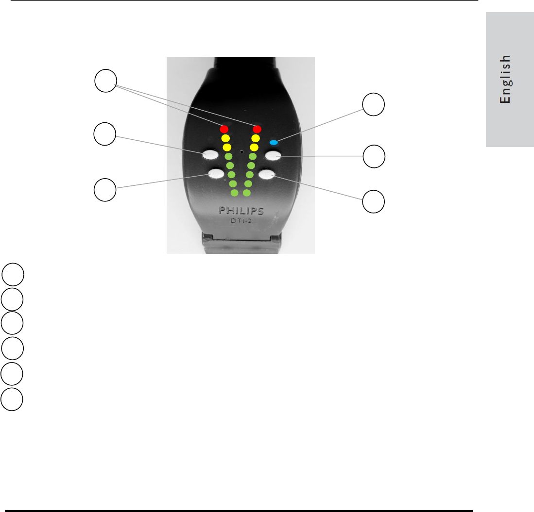
User interface
1 LED arrays
2 Bluetooth button
3 On/off button
4 Bluetooth LED
5 Status button
6 Event marker button
Two 8-piece LED arrays are available for communications to the wearer.
The arrays lit when the device switches on or off. When the status button
is switched the skin conductance level and skin temperature are visible
for 10 seconds. When the Bluetooth active a blue LED is visible above
the Status button.
3 Intended use
The device is to be used to monitor at the left or right wrist of humans:
the skin conductance, skin temperature, ambient temperature, ambient
light level, and 3-dimensional acceleration. The sensor data can be
streamed live to a receiving station via a Bluetooth wireless link. The
device is to not to be used as a medical device. Hence no diagnosis or
treatment of a medical illness can or may be performed based on the
data obtained by this device.
2
1
1
6
3
5
4
1
EN 9
4 How to use the device
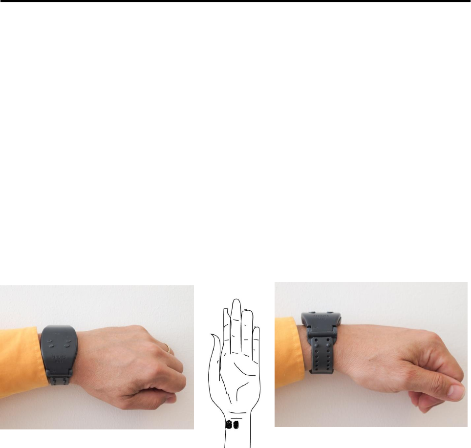
Wearing instructions
The device is worn on the left or right wrist. If a wristwatch is worn, the
DTI-2 should be worn on the other wrist. The position should as close to
the hand as possible without discomfort or hindering any hand postures.
The strap closure is at the side of the thumb. The DTI-2 is fixed to the
wrist with a flexible strap. Please pay attention to the level of tightening.
The wrist band should be fixed to the wrist, i.e. not dangling loose. The
wrist band should however be comfortable to wear and not strapped too
tight. Optimal is the loosest strap position without dangling.
Place the rubber strap on the underside of the wrist, such that the skin
conductance electrodes contact a desired area of the skin:
recommended is to center the electrode furthest from the thumb and
wrap the strap towards the electronics module.
Recommended position of the wristband sensor skin conductance
electrode for best results.
Switching the device on/off
The unit is switched on by pressing the on/off button continuously for
more than 4 seconds. When activated the device flashes the LED
arrays to indicate readiness.
The device goes into sleep mode by pressing continuously for more
than 4 seconds on the on/off button when the device is in active mode.
When this happens the rows of LEDs light up briefly.

10 EN
Bluetooth wireless data transmission
During use the Bluetooth wireless data transmission can be started by
pressing the top right button, which is the Bluetooth activation button. A
Blue LED situated top right starts blinking and stays lit during Bluetooth
listening. For first time use the device needs to be linked to the receiving
device. The pairing code is 0000. On the embedded microSD card a
program called DTI-2 Streaming Data Viewer is available, which can
visualize the transmitted data on a Windows computer. Connect the
DTI-2 to the computer with the USB cable to mount the microSD card as
a directory, and run setup to install the program.
Event marker
During use events can be marked into the database using the lower left
button, which is the Event marker button. Both rows of LEDs light up to
indicate that an event marker has been recorded into the database.
Status button
During use the current skin conductance and skin temperature status can
be visualized by means of the two LED arrays using lower right button,
which is the status button. The left array shows the skin temperature: all
LEDs on means 38 degrees Celsius. The decrement is 1 degree per
LED, so one LED lit means 31 degrees Celsius. The right array shows
the skin conductance normalized to the average of the last minute
(3LEDs on). Per increment of 1%, a LED switches on or off. This allows a
visualization of the recent skin conductance changes.
Time synchronization
The DTI-2 can keep track of time and date. In active mode and in sleep
mode the internal real time clock takes care of this. All measured sensor
data is time stamped and stored in a data file on the microSD card.
Before active use of the DTI-2 it needs to be synchronized with a
Windows 7 PC to ensure accurate time stamping.
Two methods are available for synchronization:
1) Connect the DTI-2 to a PC the USB cable. In the DTI2-0XXX drive
(XXX being the serial number of the DTI-2) double click
CreateDTITIME.bat to create a file named DTITime.txt. Unhook the
device immediately after writing and switch it on. The creation
time/date of the DTITime.txt file is used as synchronization time.
CAUTION: the latency between the creation time/date of the
DTITime.txt file and switching on the DTI-2 is not taken into
EN 11
account, which causes an error in the synchronization of at least
several seconds.
2) Establish a Bluetooth link with the DTI-2 and start up the
DTI-2_BT_StreamingDataViewer program that can be found on the
internal data storage of the DTI-2. After opening the communication
in this program synchronization will take place automatically.
Battery charging
Battery recharging is done with the supplied USB charger via the USB
cable, which needs to be inserted into the USB connector that can be
found behind the fastening hinge. A red LED placed close to the USB
connector indicates active charging. It takes about 2 hours to charge the
device from empty to full. The red LED may not switch off when a full
charge state is realized. The sure way to check whether the battery has a
full charge is to unplug the USB cable, and to plug it in again: when the
red LED stays out the battery is fully charged.
Data Readout
1) Connect it to a Windows7/Vista/XP™ PC with the USB cable. A blue
LED close to the USB connector indicates a functional USB
connection.
2) The device mounts as ‘’Device with Removable Storage’’ on your PC.
Open the explorer and click the drive associated with the DTI-2
(should this fail to happen unplug the USB cable and reconnect it).
When asked to scan and fix the device, please comply, and tick both
check disk options. After the scan the DTI-2 drive mounts normally.
3) Copy the data files to a location of your choice on your own computer.
4) Undock the device after this operation
Data format and data visualization
The measured data is stored in a binary file named DTISamples0XXX.dti,
where XXX is the serial number of the device. This file can be converted
into a text file with the DTI-2_SampleFileParser-P program which is
present on the DTI-2 data storage disk. Run this program, select the .dti
file, and choose Convert DTI Sample File. This will generate a text file
with all data in lines with this format:
yyyymmddHHMMSSmmm|NNNN|ev|ttttt|sksks|xxxxx|yyyyy|zzzzz|vb|etete|eieie|rrrrr
A minus sign may precede the accelerometer data xxxxx, yyyyy or zzzzz. The
description of the line coding is given in the next Table.
12 EN
Layout code
Description
width
Format
yyyy
Year
4
201x
mm
Month
2
01-12
dd
Day
2
01-31
HH
Hours
2
00-24
MM
Minutes
2
00-60
SS
Seconds
2
00-60
mmm
milli seconds
3
000-999
NNNN
Serial number
4
0001-9999
ev
Event
2
1=button; 2=detected
ttttt
Skin Temperature
5
100x oC
sksks
Skin Conductance
5
nano Siemens
xxxxx|yyyyy|zzzzz
3D acceleration (x,y,z)
15
counts (16384 = 1 g)
vb
Battery voltage
2
10x Voltage
etete
Ambient temperature
5
100x oC
eieie
Ambient light level
5
Counts
rrrrr
Skin conductance ADC
5
16bit raw ADC output
snr
Dataset number
8
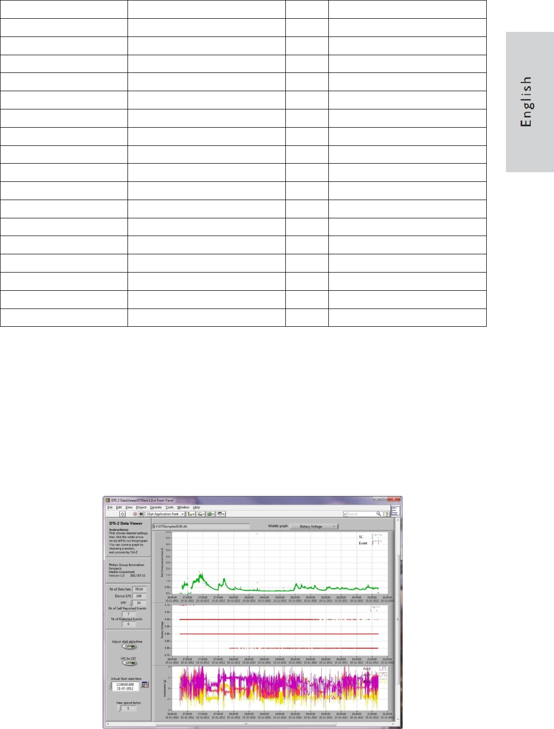
The visualization can be done using the DTI-2 Data Viewer program.
This can be installed from the integrated data storage of the DTI-2.
Connect the device to a computer with a USB cable.The DTI-2 mounts
as ‘’Device with Removable Storage’’ on your computer. Open the
explorer and click the drive associated with the DTI-2 (should this fail to
happen unplug the USB cable and reconnect it). In the directory
DTI-2_DTIfileDataViewerV1.0 Installer a program called setup.exe is
located, which installs the data viewer program onto your (Microsoft
Windows7/Vista/XP™) computer. A screenshot is shown below.

EN 13
5 Product Information
Dimensions
39.5 x 12 x 63.5 mm
Weight
40 g
Power supply
Charger: Input: AC 100-240V, 50/60 Hz
Output: DC 5V 0.5A
Battery: 3.7V 400mAh Lithium Polymer
Battery life
30 hours without wireless data streaming
12 hours with wireless data streaming
Operating temperature range
-20 – 50oC (-4 – 122oF)
USB
2.0
Skin conductance sensor
0.01-65.5 micro Siemens range
0.001 micro Siemens sensitivity
Silver coated Eyelet A3822C2 Micron electrodes
Skin temperature sensor
-20 – 85oC range
0.02oC sensitivity
100o field of view
Ambient temperature sensor
-40 – 125oC range
0.5 – 2oC accuracy (best at 40oC)
Ambient light sensor
24.4 counts/µW/cm2 responsivity at 640nm
for the VIS-IR diode
6.9 counts/µW/cm2 responsivity at 940 nm for
the IR diode
3D accelerometer
±2g range
0.001 g per bit sensitivity
Wireless connection
Bluetooth 2.1
Data storage
2GB microSD card
Sampling frequency
2-25 Hz firmware dependent