Philips Medical Systems North America M2601A-95 Medical Telemetry Transmitter User Manual
Philips Medical Systems North America Co. Medical Telemetry Transmitter
UserManual.wiki
>
Philips Medical Systems North America
>
M2601A 95 User Manual
User Guide
Navigation menu
Upload a User Manual
Namespaces
Wiki Guide
HTML
PDF
Info
Views
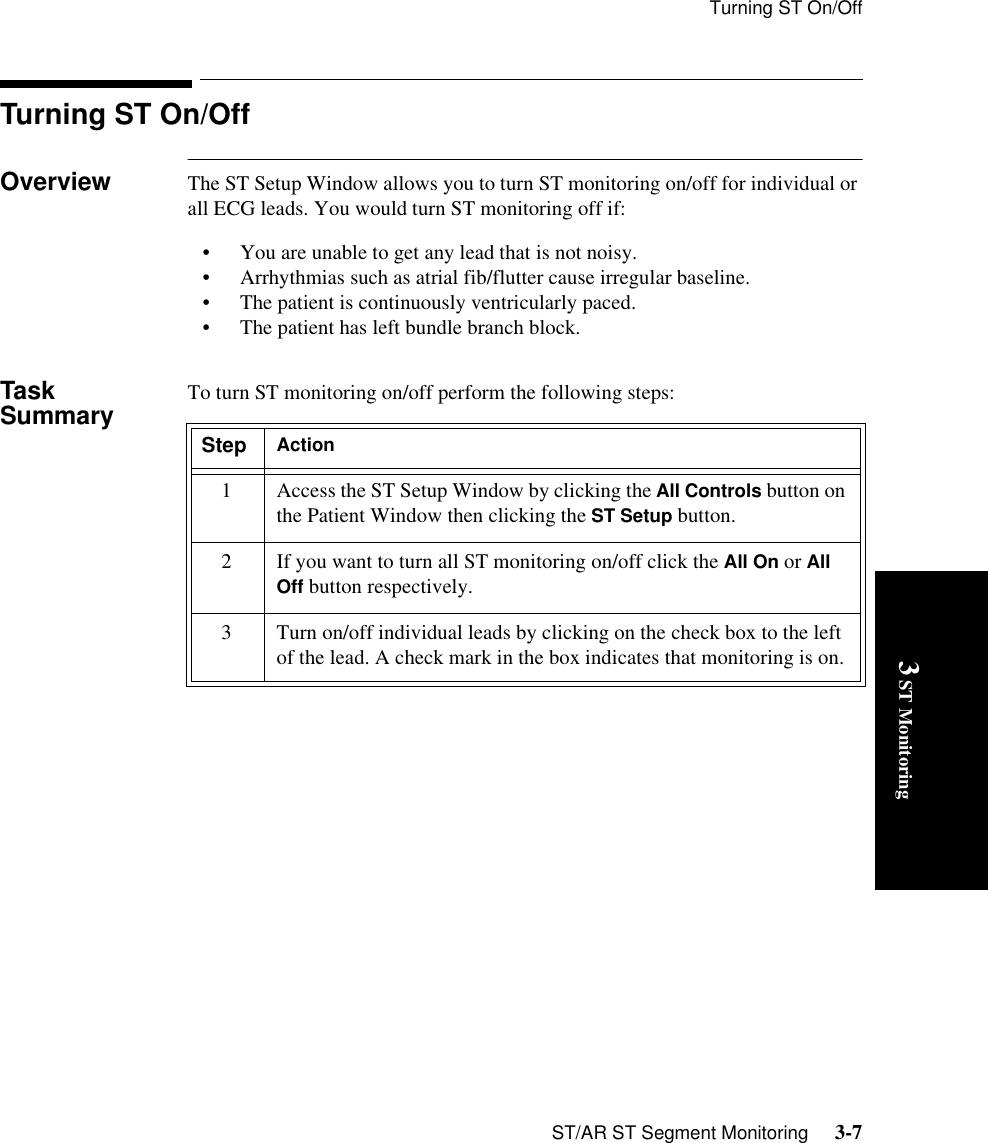
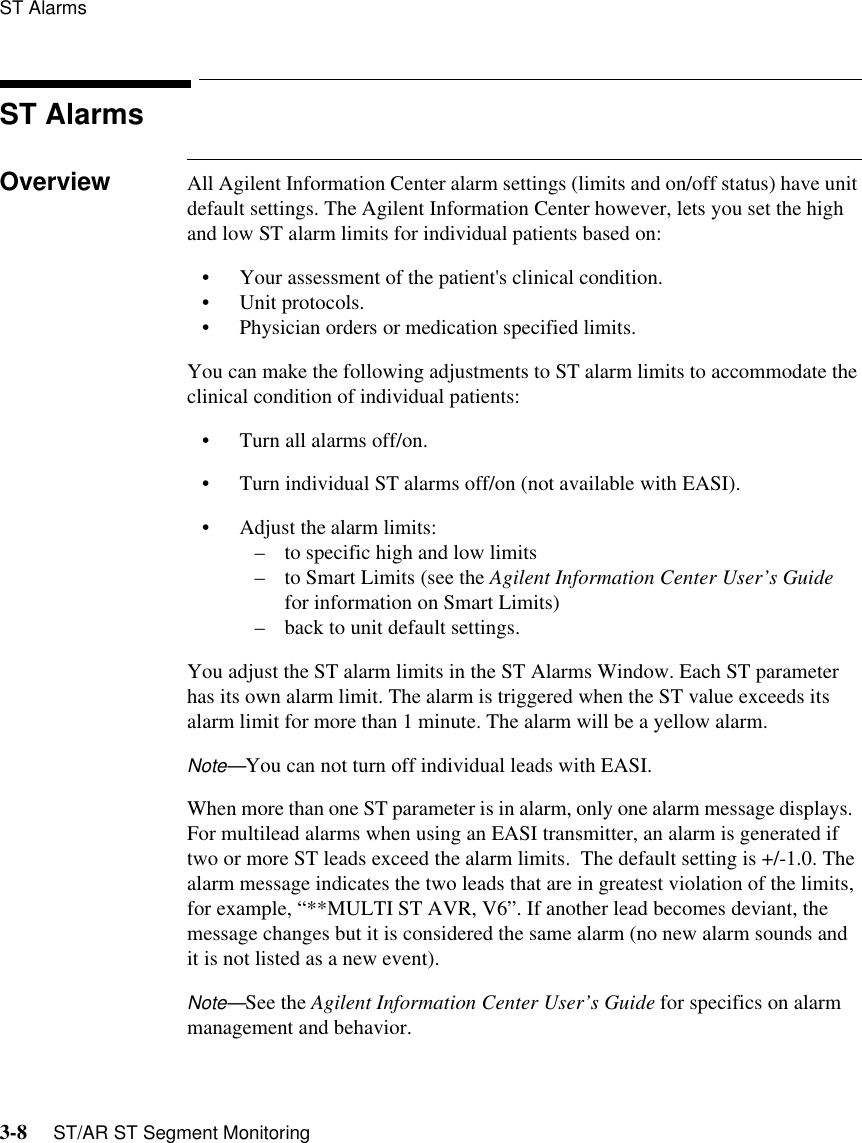
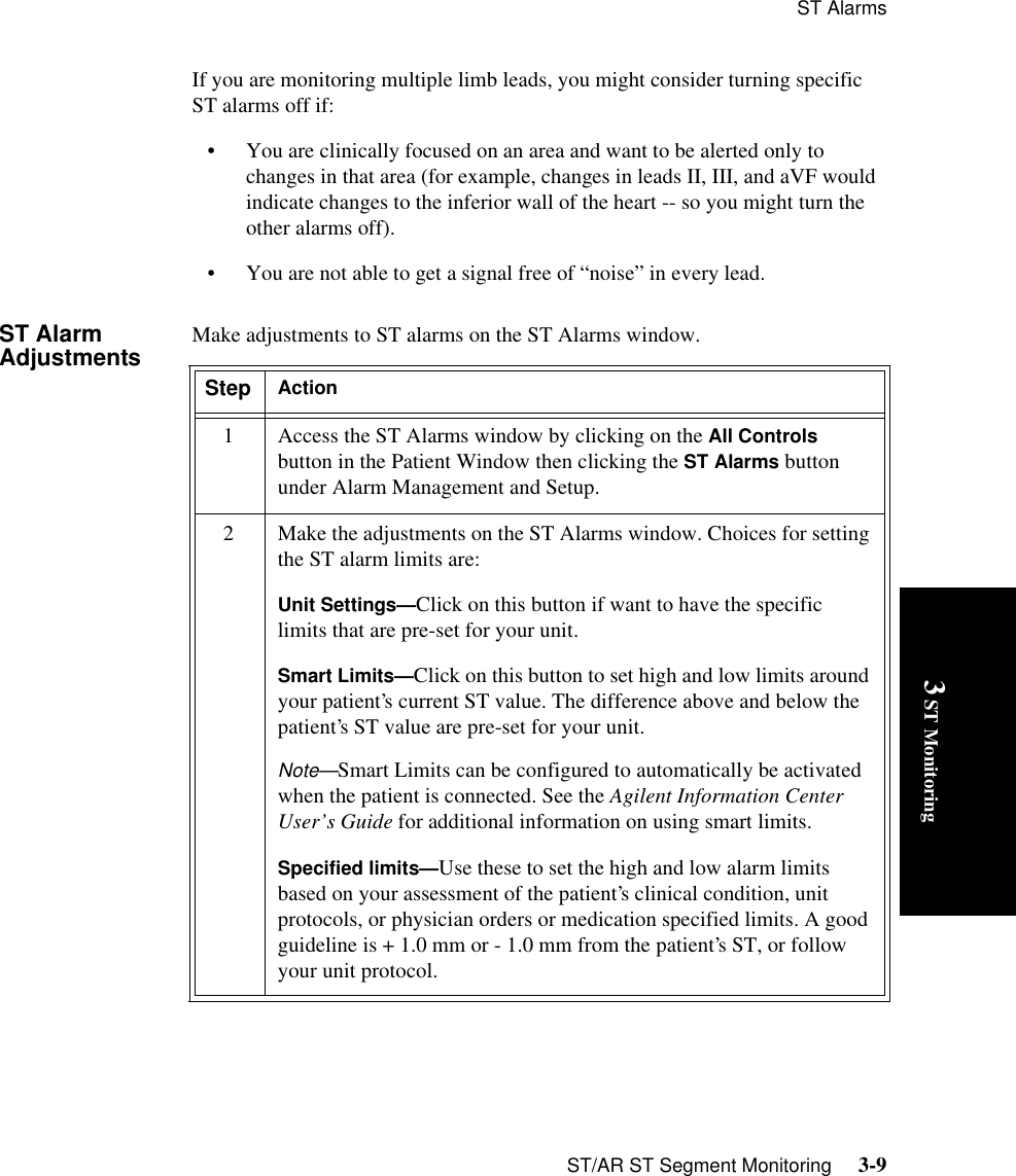
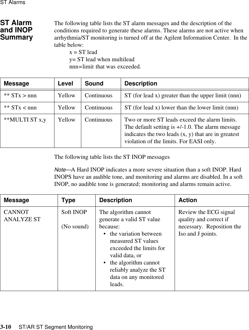
User Manual
Discussion / Help
Navigation
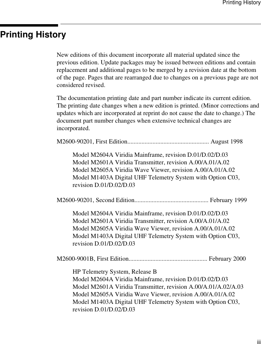

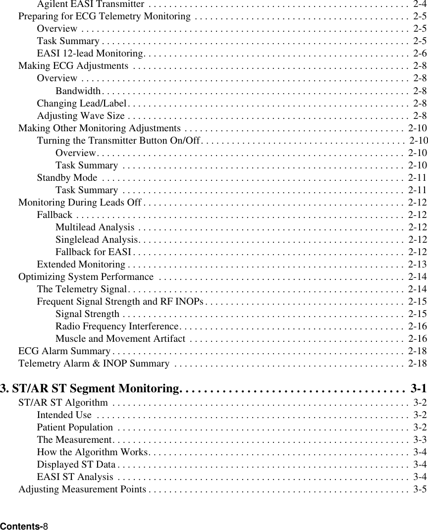

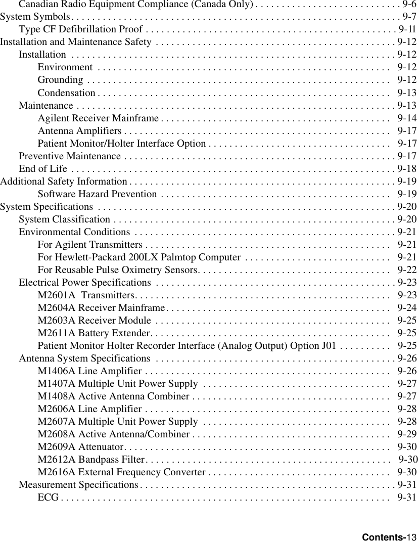

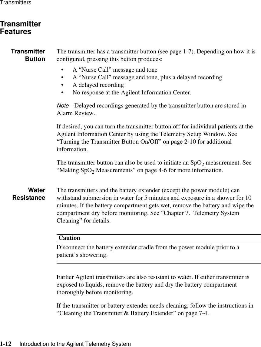


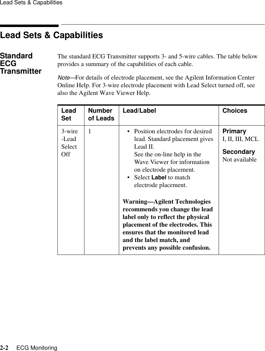
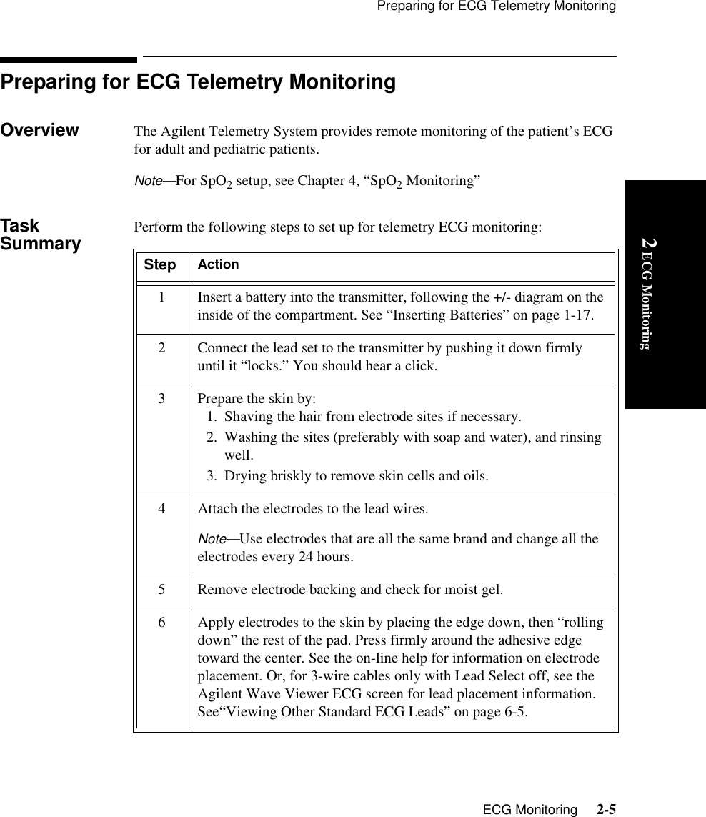

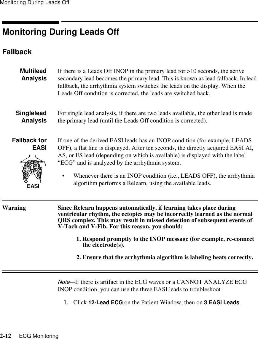
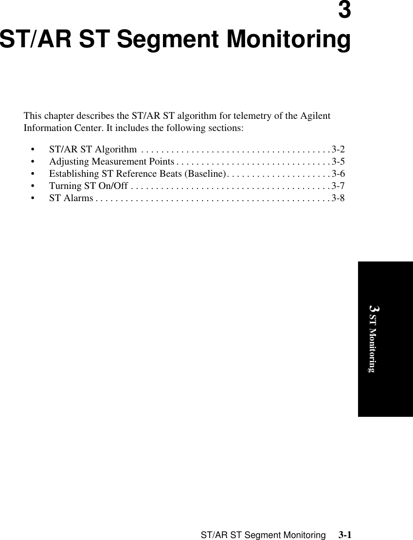
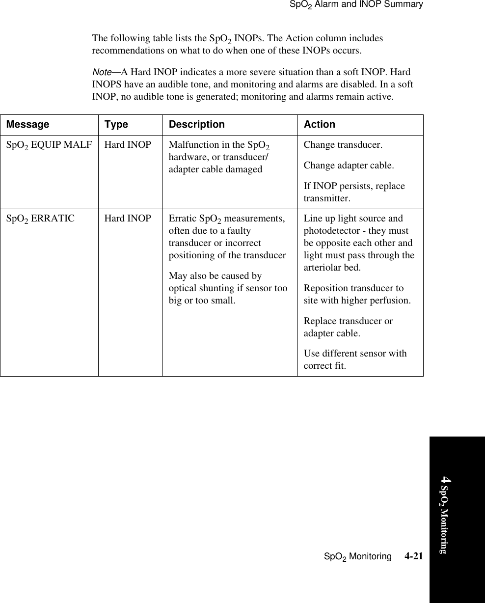

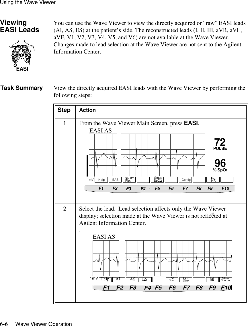
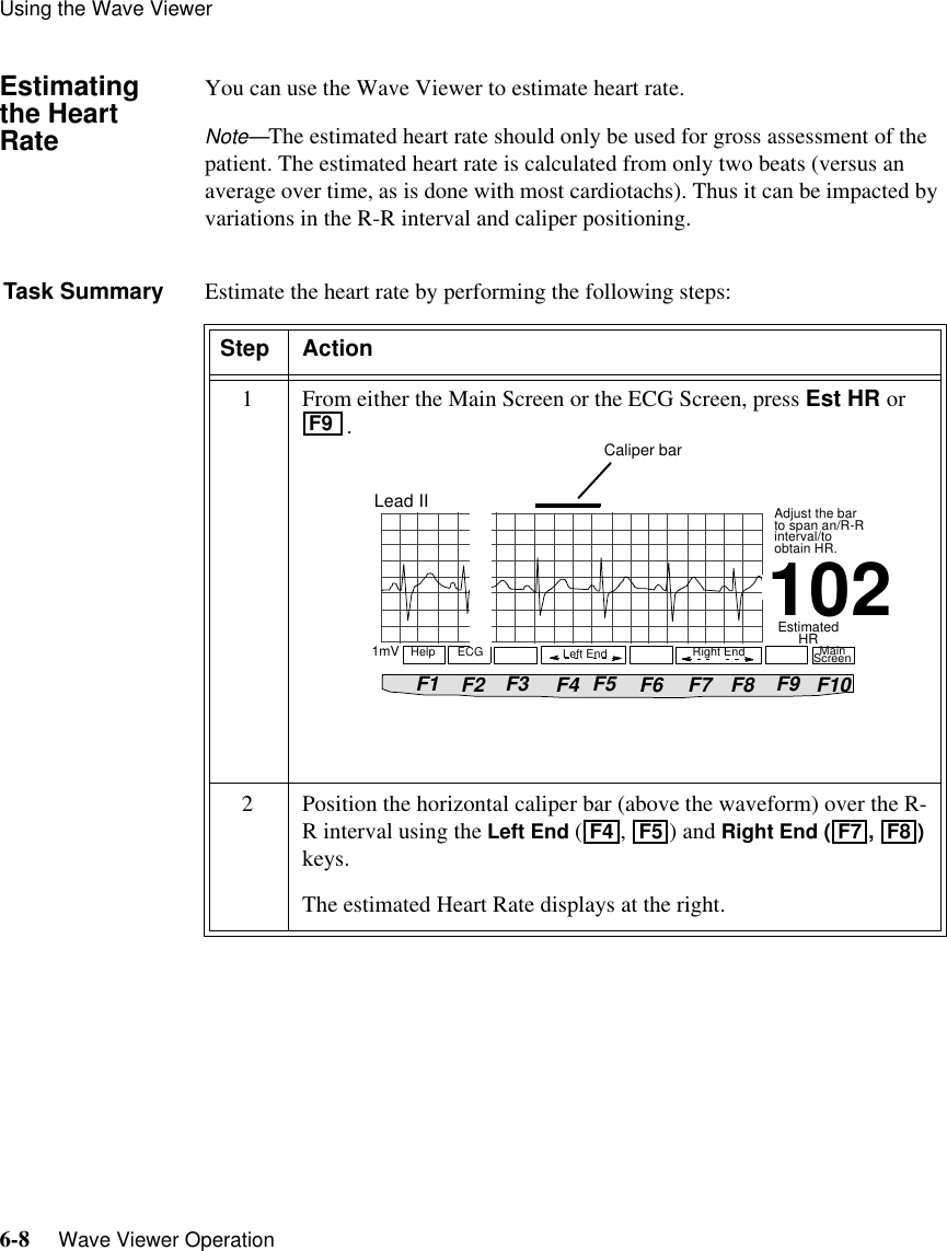
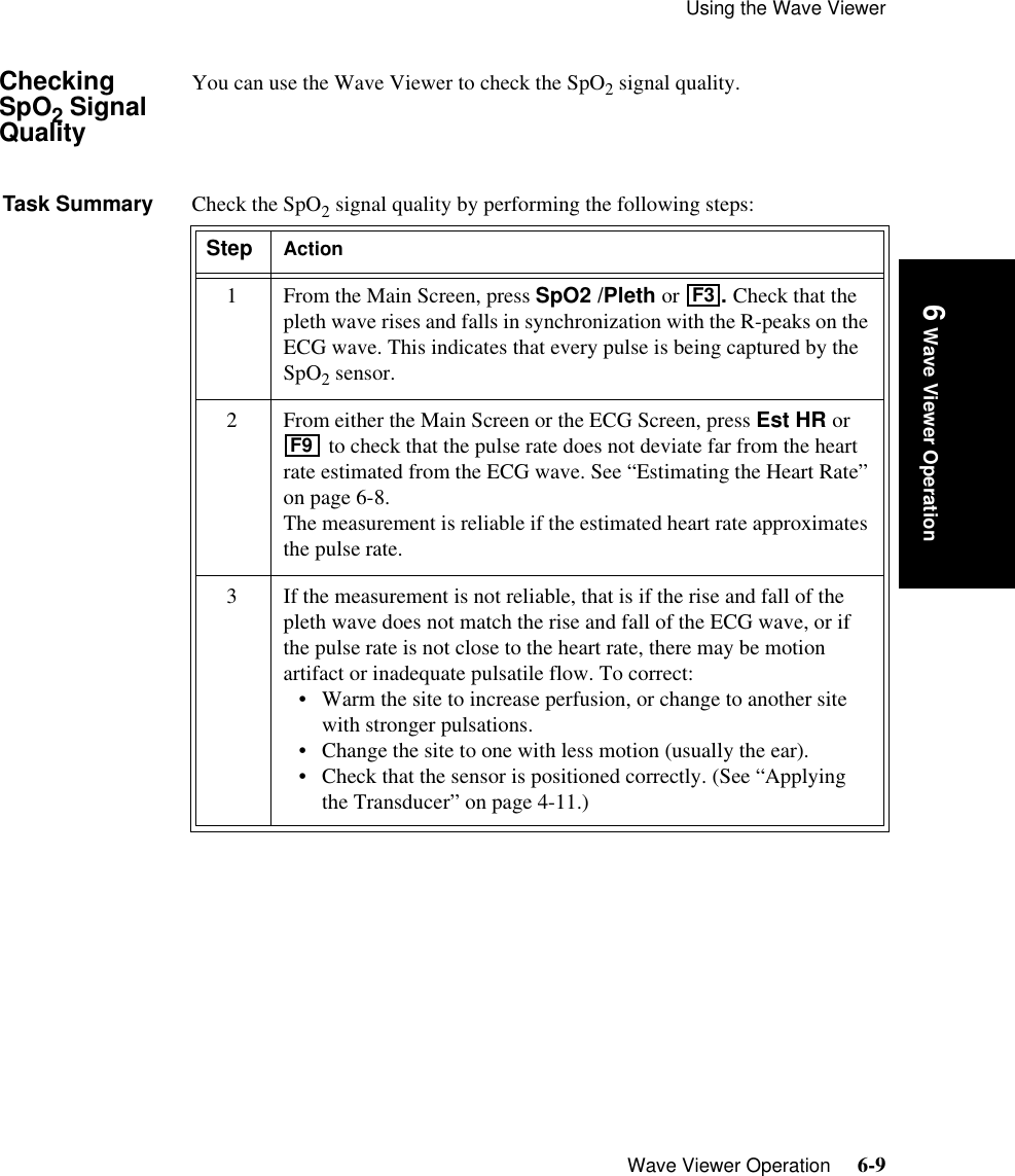
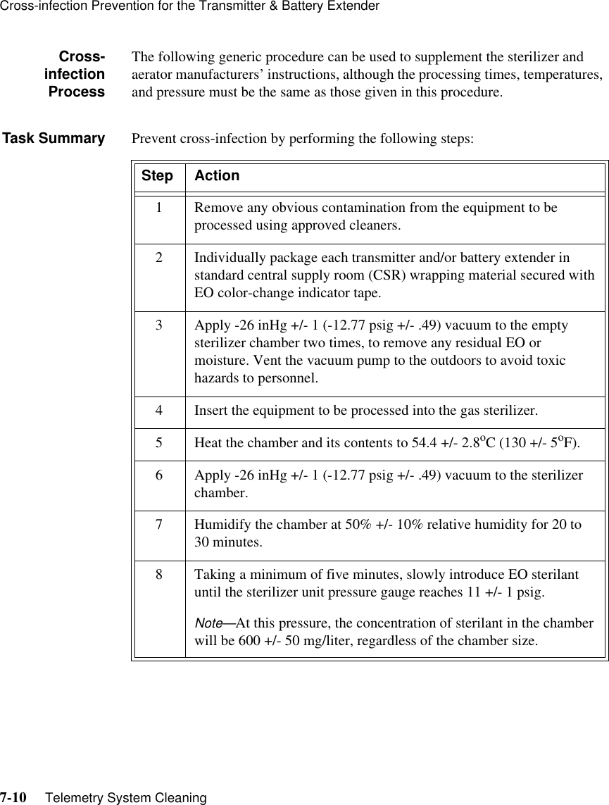

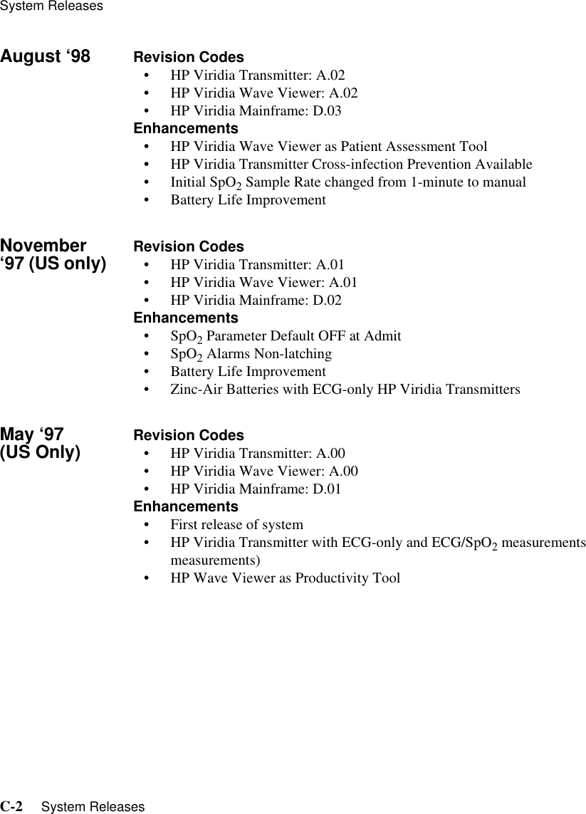
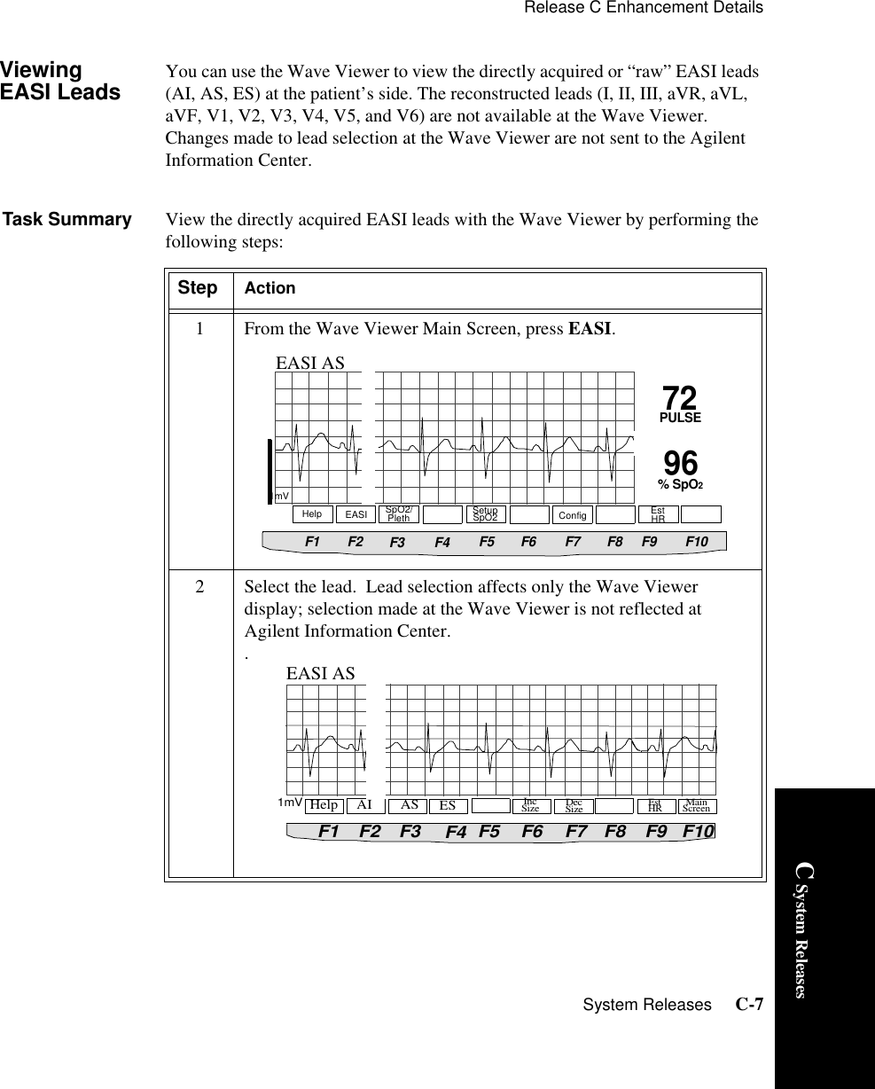
![Release C Enhancement DetailsC-4 System ReleasesDuring INOPs If one of the derived EASI leads has an INOP condition (i.e., LEADS OFF), a flat line is displayed. After ten seconds, the directly acquired EASI AI, AS, or ES lead (depending on which is available) is displayed with the label “ECG” and is analyzed by the arrhythmia system. This feature is called “fallback.” To summarize, whenever there is an INOP condition with EASI, the arrhythmia algorithm performs a Relearn, using the available “raw” leads. Note—If there is artifact in the ECG waves or a CANNOT ANALYZE ECG INOP condition, you can use the three EASI leads to troubleshoot.1. Click 12-Lead ECG on the Patient Window, then on 3 EASI Leads. 2. The three directly acquired EASI leads will be displayed so that you can determine which electrodes are causing the problem and need to be replaced.Warning Since Relearn happens automatically, if learning takes place during ventricular rhythm, the ectopics may be incorrectly learned as the normal QRS complex. This may result in missed detection of subsequent events of V-Tach and V-Fib. For this reason, you should:1. Respond tpromptly o the INOP message [for example, re-connect the electrode(s)]. 2. Ensure that the arrhythmia algorithm is labeling beats correctly.](https://usermanual.wiki/Philips-Medical-Systems-North-America/M2601A-95/User-Guide-241951-Page-204.png)
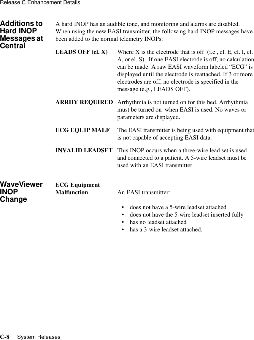
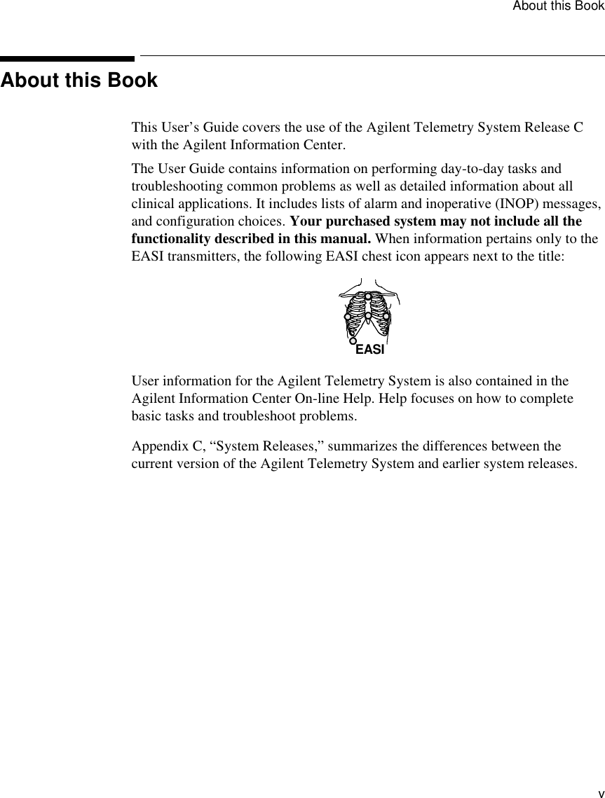
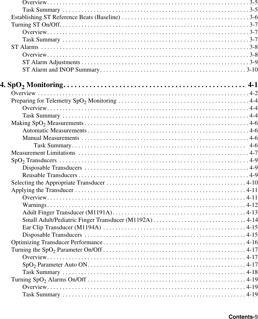
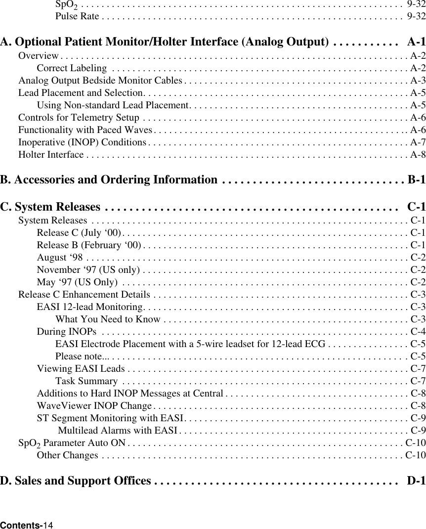
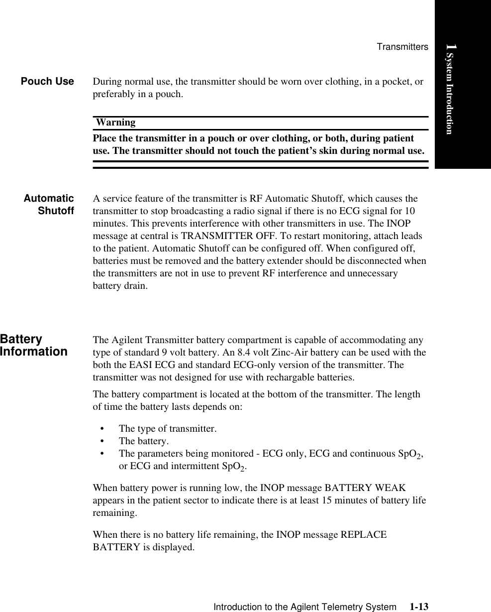
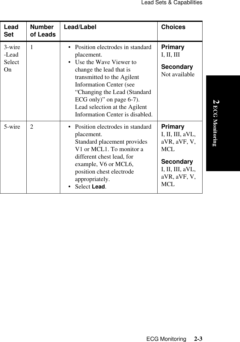
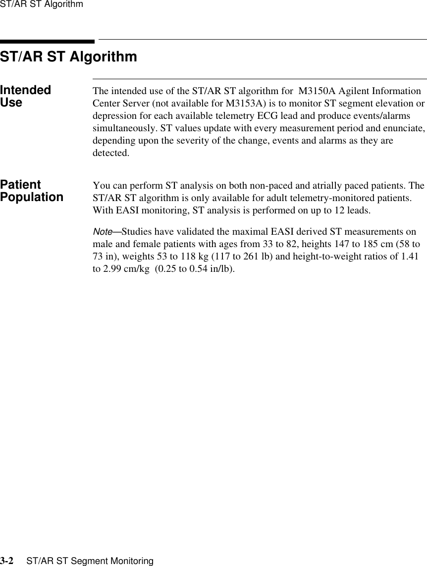
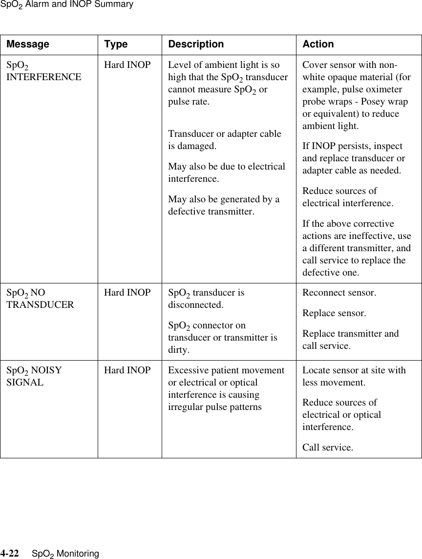
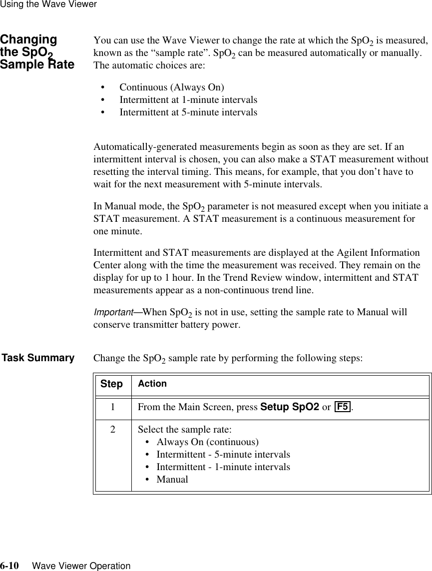
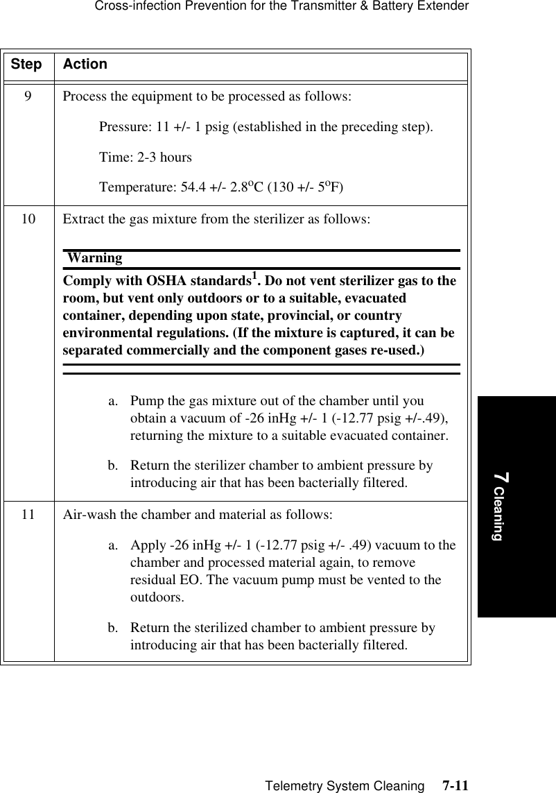
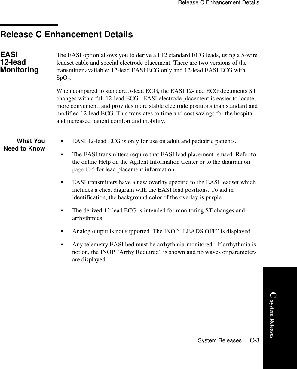
![Release C Enhancement DetailsSystem Releases C-5C System ReleasesEASI ElectrodePlacementwith a5-wire leadsetfor 12-leadECGElectrode labels and colors are given for AAMI norm and in square brackets [-] for IEC norm.E - Brown [IEC: White] electrode - place on the lower sternum at the level of the fifth intercostal space.A - Red [IEC: Green] electrode - place on the left midaxillary line at the same level as the E electrode. S - Black [IEC: Yellow] electrode - place on the upper sternum.I - White [IEC: Red] electrode - place on the right midaxillary line at the same level as the E electrode.Reference -Green [IEC: Black] electrode - place ground electrode anywhere (usually below the 6th rib on right hip).Please note... • When placing electrodes, be careful to place the electrodes as accurately as possible or the derived leads may be incorrect. If necessary, the AI electrodes may be shifted down or up , or the ES electrodes may be shifted left or right, but the AI and ES electrodes must still be at right angles. The following guidelines should be followed:– When plaster or therapeutic equipment restricts electrode placement, the E and S electrodes can be moved in parallel to the patient’s right, but keep this move as small as possible.12345EIASREF](https://usermanual.wiki/Philips-Medical-Systems-North-America/M2601A-95/User-Guide-241951-Page-205.png)