Philips Medical Systems North America M2601A-95 Medical Telemetry Transmitter User Manual
Philips Medical Systems North America Co. Medical Telemetry Transmitter
User Guide

Agilent Telemetry System
User’s Guide
Part Number M2600-9001C
Printed in the U.S.A. July 2000
Edition 1

Copyright © 2000 by Agilent Technologies Inc.
Notice
This document contains proprietary information which is protected by copyright.
All Rights Reserved. Reproduction, adaptation, or translation without prior
written permission is prohibited, except as allowed under the copyright laws.
Agilent Technologies, Inc.
3000 Minuteman Road
Andover, MA 01810-1099
(978) 687-1501
Publication number
M2600-9001C, Edition 1
Printed in USA July 2000
HP and Hewlett-Packard are registered trademarks of Hewlett-Packard
Company.
EASI™ is a registered trademark of Zymed, Inc.
Warranty The information contained in this document is subject to change without notice.
Agilent Technologies makes no warranty of any kind with regard to this
material, including, but not limited to, the implied warranties or merchantability
and fitness for a particular purpose.
Agilent Technologies shall not be liable for errors contained herein or for
incidental or consequential damages in connection with the furnishing,
performance, or use of this material.

Printing History
iii
Printing History
New editions of this document incorporate all material updated since the
previous edition. Update packages may be issued between editions and contain
replacement and additional pages to be merged by a revision date at the bottom
of the page. Pages that are rearranged due to changes on a previous page are not
considered revised.
The documentation printing date and part number indicate its current edition.
The printing date changes when a new edition is printed. (Minor corrections and
updates which are incorporated at reprint do not cause the date to change.) The
document part number changes when extensive technical changes are
incorporated.
M2600-90201, First Edition.................................................... August 1998
Model M2604A Viridia Mainframe, revision D.01/D.02/D.03
Model M2601A Viridia Transmitter, revision A.00/A.01/A.02
Model M2605A Viridia Wave Viewer, revision A.00/A.01/A.02
Model M1403A Digital UHF Telemetry System with Option C03,
revision D.01/D.02/D.03
M2600-90201, Second Edition............................................... February 1999
Model M2604A Viridia Mainframe, revision D.01/D.02/D.03
Model M2601A Viridia Transmitter, revision A.00/A.01/A.02
Model M2605A Viridia Wave Viewer, revision A.00/A.01/A.02
Model M1403A Digital UHF Telemetry System with Option C03,
revision D.01/D.02/D.03
M2600-9001B, First Edition.................................................. February 2000
HP Telemetry System, Release B
Model M2604A Viridia Mainframe, revision D.01/D.02/D.03
Model M2601A Viridia Transmitter, revision A.00/A.01/A.02/A.03
Model M2605A Viridia Wave Viewer, revision A.00/A.01/A.02
Model M1403A Digital UHF Telemetry System with Option C03,
revision D.01/D.02/D.03
Printing History
iv
M2600-9001C, First Edition.................................................. July 2000
Agilent Telemetry System, Release C
Model M2604A Agilent Mainframe, revision E.00
Model M2601A Agilent Transmitter, revision B.00
Model M2605A Agilent Wave Viewer, revision B.00
Details about the specific releases are contained in Appendix C.

About this Book
v
About this Book
This User’s Guide covers the use of the Agilent Telemetry System Release C
with the Agilent Information Center.
The User Guide contains information on performing day-to-day tasks and
troubleshooting common problems as well as detailed information about all
clinical applications. It includes lists of alarm and inoperative (INOP) messages,
and configuration choices. Your purchased system may not include all the
functionality described in this manual. When information pertains only to the
EASI transmitters, the following EASI chest icon appears next to the title:
User information for the Agilent Telemetry System is also contained in the
Agilent Information Center On-line Help. Help focuses on how to complete
basic tasks and troubleshoot problems.
Appendix C, “System Releases,” summarizes the differences between the
current version of the Agilent Telemetry System and earlier system releases.
1
2
3
4
5
EASI

About this Book
vi
Document
Conventions Procedures
Procedures are indicated in text by the heading “Task Summary” followed by
the following table:
Bold Typeface
Objects of actions in procedures appear in bold typeface. Note the following
example:
Click the Update button.
Warnings
Warning
Warnings are information you should know to avoid injuring patients and
personnel.
Cautions
Caution
Cautions are information you should know to avoid damaging your equipment
and software.
Notes
Note—
Notes contain additional information on the Agilent Telemetry System
usage.
Step Action
1
2
3

Contents
Contents-7
1. Introduction to the Agilent Telemetry System. . . . . . . . . . . . . . . . . . . . . . . . . 1-1
Indications for Use. . . . . . . . . . . . . . . . . . . . . . . . . . . . . . . . . . . . . . . . . . . . . . . . . . . . . . . . . . . . . 1-2
Condition . . . . . . . . . . . . . . . . . . . . . . . . . . . . . . . . . . . . . . . . . . . . . . . . . . . . . . . . . . . . 1-2
Prescription Versus Over-the-Counter . . . . . . . . . . . . . . . . . . . . . . . . . . . . . . . . . . . . . 1-2
Part of the Body or Type of Tissue with which the Device Interacts . . . . . . . . . . . . . . 1-2
Frequency of Use. . . . . . . . . . . . . . . . . . . . . . . . . . . . . . . . . . . . . . . . . . . . . . . . . . . . . . 1-2
Physiological Purpose . . . . . . . . . . . . . . . . . . . . . . . . . . . . . . . . . . . . . . . . . . . . . . . . . . 1-2
Patient Population . . . . . . . . . . . . . . . . . . . . . . . . . . . . . . . . . . . . . . . . . . . . . . . . . . . . . 1-2
Intended Use . . . . . . . . . . . . . . . . . . . . . . . . . . . . . . . . . . . . . . . . . . . . . . . . . . . . . . . . . 1-3
System Overview. . . . . . . . . . . . . . . . . . . . . . . . . . . . . . . . . . . . . . . . . . . . . . . . . . . . . . . . . . . . . . 1-4
Dual-band Operation . . . . . . . . . . . . . . . . . . . . . . . . . . . . . . . . . . . . . . . . . . . . . . . . . . . 1-4
Transmitters . . . . . . . . . . . . . . . . . . . . . . . . . . . . . . . . . . . . . . . . . . . . . . . . . . . . . . . . . . . . . . . . . . 1-6
Agilent Transmitters . . . . . . . . . . . . . . . . . . . . . . . . . . . . . . . . . . . . . . . . . . . . . . . . . . . . . . . . 1-7
Agilent Telemetry Battery Extender. . . . . . . . . . . . . . . . . . . . . . . . . . . . . . . . . . . . . . . . . . . . 1-9
Transmitter Features . . . . . . . . . . . . . . . . . . . . . . . . . . . . . . . . . . . . . . . . . . . . . . . . . . . . . . .1-12
Transmitter Button. . . . . . . . . . . . . . . . . . . . . . . . . . . . . . . . . . . . . . . . . . . . . . . . . . . . 1-12
Water Resistance . . . . . . . . . . . . . . . . . . . . . . . . . . . . . . . . . . . . . . . . . . . . . . . . . . . . . 1-12
Pouch Use . . . . . . . . . . . . . . . . . . . . . . . . . . . . . . . . . . . . . . . . . . . . . . . . . . . . . . . . . . 1-13
Automatic Shutoff . . . . . . . . . . . . . . . . . . . . . . . . . . . . . . . . . . . . . . . . . . . . . . . . . . . . 1-13
Battery Information. . . . . . . . . . . . . . . . . . . . . . . . . . . . . . . . . . . . . . . . . . . . . . . . . . . . . . . . 1-13
Use of Zinc-Air Batteries. . . . . . . . . . . . . . . . . . . . . . . . . . . . . . . . . . . . . . . . . . . . . . . 1-14
Maximizing Battery Life . . . . . . . . . . . . . . . . . . . . . . . . . . . . . . . . . . . . . . . . . . . . . . . 1-15
Disposal of Batteries . . . . . . . . . . . . . . . . . . . . . . . . . . . . . . . . . . . . . . . . . . . . . . . . . . 1-15
Nominal Battery Life Expectancy . . . . . . . . . . . . . . . . . . . . . . . . . . . . . . . . . . . . . . . . 1-16
Inserting Batteries . . . . . . . . . . . . . . . . . . . . . . . . . . . . . . . . . . . . . . . . . . . . . . . . . . . . 1-17
Receiver Module . . . . . . . . . . . . . . . . . . . . . . . . . . . . . . . . . . . . . . . . . . . . . . . . . . . . . . . . . . . . . 1-20
Receiver Mainframe. . . . . . . . . . . . . . . . . . . . . . . . . . . . . . . . . . . . . . . . . . . . . . . . . . . . . . . . . . . 1-21
Turning the Receiver Mainframe On or Off . . . . . . . . . . . . . . . . . . . . . . . . . . . . . . . . 1-21
Receiver Mainframe Malfunction Light . . . . . . . . . . . . . . . . . . . . . . . . . . . . . . . . . . . 1-21
Channel Frequencies . . . . . . . . . . . . . . . . . . . . . . . . . . . . . . . . . . . . . . . . . . . . . . . . . . 1-22
Retaining Telemetry Settings . . . . . . . . . . . . . . . . . . . . . . . . . . . . . . . . . . . . . . . . . . . 1-22
Antenna System . . . . . . . . . . . . . . . . . . . . . . . . . . . . . . . . . . . . . . . . . . . . . . . . . . . . . . . . . . . . . . 1-22
Turning Telemetry On/Off. . . . . . . . . . . . . . . . . . . . . . . . . . . . . . . . . . . . . . . . . . . . . . . . . . . . . . 1-23
2. ECG Monitoring . . . . . . . . . . . . . . . . . . . . . . . . . . . . . . . . . . . . . . . . . . . . . . . . . 2-1
Lead Sets & Capabilities . . . . . . . . . . . . . . . . . . . . . . . . . . . . . . . . . . . . . . . . . . . . . . . . . . . . . . . . 2-2
Standard ECG Transmitter . . . . . . . . . . . . . . . . . . . . . . . . . . . . . . . . . . . . . . . . . . . . . . . . . . . 2-2
Contents-8
Agilent EASI Transmitter . . . . . . . . . . . . . . . . . . . . . . . . . . . . . . . . . . . . . . . . . . . . . . . . . . . 2-4
Preparing for ECG Telemetry Monitoring . . . . . . . . . . . . . . . . . . . . . . . . . . . . . . . . . . . . . . . . . . 2-5
Overview . . . . . . . . . . . . . . . . . . . . . . . . . . . . . . . . . . . . . . . . . . . . . . . . . . . . . . . . . . . . . . . . 2-5
Task Summary . . . . . . . . . . . . . . . . . . . . . . . . . . . . . . . . . . . . . . . . . . . . . . . . . . . . . . . . . . . . 2-5
EASI 12-lead Monitoring. . . . . . . . . . . . . . . . . . . . . . . . . . . . . . . . . . . . . . . . . . . . . . . . . . . . 2-6
Making ECG Adjustments . . . . . . . . . . . . . . . . . . . . . . . . . . . . . . . . . . . . . . . . . . . . . . . . . . . . . . 2-8
Overview . . . . . . . . . . . . . . . . . . . . . . . . . . . . . . . . . . . . . . . . . . . . . . . . . . . . . . . . . . . . . . . . 2-8
Bandwidth. . . . . . . . . . . . . . . . . . . . . . . . . . . . . . . . . . . . . . . . . . . . . . . . . . . . . . . . . . . . 2-8
Changing Lead/Label. . . . . . . . . . . . . . . . . . . . . . . . . . . . . . . . . . . . . . . . . . . . . . . . . . . . . . . 2-8
Adjusting Wave Size . . . . . . . . . . . . . . . . . . . . . . . . . . . . . . . . . . . . . . . . . . . . . . . . . . . . . . . 2-8
Making Other Monitoring Adjustments . . . . . . . . . . . . . . . . . . . . . . . . . . . . . . . . . . . . . . . . . . . 2-10
Turning the Transmitter Button On/Off. . . . . . . . . . . . . . . . . . . . . . . . . . . . . . . . . . . . . . . . 2-10
Overview. . . . . . . . . . . . . . . . . . . . . . . . . . . . . . . . . . . . . . . . . . . . . . . . . . . . . . . . . . . . 2-10
Task Summary . . . . . . . . . . . . . . . . . . . . . . . . . . . . . . . . . . . . . . . . . . . . . . . . . . . . . . . 2-10
Standby Mode . . . . . . . . . . . . . . . . . . . . . . . . . . . . . . . . . . . . . . . . . . . . . . . . . . . . . . . . . . . 2-11
Task Summary . . . . . . . . . . . . . . . . . . . . . . . . . . . . . . . . . . . . . . . . . . . . . . . . . . . . . . . 2-11
Monitoring During Leads Off . . . . . . . . . . . . . . . . . . . . . . . . . . . . . . . . . . . . . . . . . . . . . . . . . . . 2-12
Fallback . . . . . . . . . . . . . . . . . . . . . . . . . . . . . . . . . . . . . . . . . . . . . . . . . . . . . . . . . . . . . . . . 2-12
Multilead Analysis . . . . . . . . . . . . . . . . . . . . . . . . . . . . . . . . . . . . . . . . . . . . . . . . . . . . 2-12
Singlelead Analysis. . . . . . . . . . . . . . . . . . . . . . . . . . . . . . . . . . . . . . . . . . . . . . . . . . . . 2-12
Fallback for EASI. . . . . . . . . . . . . . . . . . . . . . . . . . . . . . . . . . . . . . . . . . . . . . . . . . . . . 2-12
Extended Monitoring . . . . . . . . . . . . . . . . . . . . . . . . . . . . . . . . . . . . . . . . . . . . . . . . . . . . . . 2-13
Optimizing System Performance . . . . . . . . . . . . . . . . . . . . . . . . . . . . . . . . . . . . . . . . . . . . . . . . 2-14
The Telemetry Signal. . . . . . . . . . . . . . . . . . . . . . . . . . . . . . . . . . . . . . . . . . . . . . . . . . . . . . 2-14
Frequent Signal Strength and RF INOPs. . . . . . . . . . . . . . . . . . . . . . . . . . . . . . . . . . . . . . . 2-15
Signal Strength . . . . . . . . . . . . . . . . . . . . . . . . . . . . . . . . . . . . . . . . . . . . . . . . . . . . . . . 2-15
Radio Frequency Interference. . . . . . . . . . . . . . . . . . . . . . . . . . . . . . . . . . . . . . . . . . . . 2-16
Muscle and Movement Artifact . . . . . . . . . . . . . . . . . . . . . . . . . . . . . . . . . . . . . . . . . . 2-16
ECG Alarm Summary. . . . . . . . . . . . . . . . . . . . . . . . . . . . . . . . . . . . . . . . . . . . . . . . . . . . . . . . . 2-18
Telemetry Alarm & INOP Summary . . . . . . . . . . . . . . . . . . . . . . . . . . . . . . . . . . . . . . . . . . . . . 2-18
3. ST/AR ST Segment Monitoring. . . . . . . . . . . . . . . . . . . . . . . . . . . . . . . . . . . . . 3-1
ST/AR ST Algorithm . . . . . . . . . . . . . . . . . . . . . . . . . . . . . . . . . . . . . . . . . . . . . . . . . . . . . . . . . . 3-2
Intended Use . . . . . . . . . . . . . . . . . . . . . . . . . . . . . . . . . . . . . . . . . . . . . . . . . . . . . . . . . . . . . 3-2
Patient Population . . . . . . . . . . . . . . . . . . . . . . . . . . . . . . . . . . . . . . . . . . . . . . . . . . . . . . . . . 3-2
The Measurement. . . . . . . . . . . . . . . . . . . . . . . . . . . . . . . . . . . . . . . . . . . . . . . . . . . . . . . . . . 3-3
How the Algorithm Works. . . . . . . . . . . . . . . . . . . . . . . . . . . . . . . . . . . . . . . . . . . . . . . . . . . 3-4
Displayed ST Data . . . . . . . . . . . . . . . . . . . . . . . . . . . . . . . . . . . . . . . . . . . . . . . . . . . . . . . . . 3-4
EASI ST Analysis . . . . . . . . . . . . . . . . . . . . . . . . . . . . . . . . . . . . . . . . . . . . . . . . . . . . . . . . . 3-4
Adjusting Measurement Points . . . . . . . . . . . . . . . . . . . . . . . . . . . . . . . . . . . . . . . . . . . . . . . . . . . 3-5
Contents-9
Overview. . . . . . . . . . . . . . . . . . . . . . . . . . . . . . . . . . . . . . . . . . . . . . . . . . . . . . . . . . . . . . . . . 3-5
Task Summary . . . . . . . . . . . . . . . . . . . . . . . . . . . . . . . . . . . . . . . . . . . . . . . . . . . . . . . . . . . . 3-5
Establishing ST Reference Beats (Baseline) . . . . . . . . . . . . . . . . . . . . . . . . . . . . . . . . . . . . . . . . . 3-6
Turning ST On/Off. . . . . . . . . . . . . . . . . . . . . . . . . . . . . . . . . . . . . . . . . . . . . . . . . . . . . . . . . . . . . 3-7
Overview. . . . . . . . . . . . . . . . . . . . . . . . . . . . . . . . . . . . . . . . . . . . . . . . . . . . . . . . . . . . . . . . . 3-7
Task Summary . . . . . . . . . . . . . . . . . . . . . . . . . . . . . . . . . . . . . . . . . . . . . . . . . . . . . . . . . . . . 3-7
ST Alarms . . . . . . . . . . . . . . . . . . . . . . . . . . . . . . . . . . . . . . . . . . . . . . . . . . . . . . . . . . . . . . . . . . . 3-8
Overview. . . . . . . . . . . . . . . . . . . . . . . . . . . . . . . . . . . . . . . . . . . . . . . . . . . . . . . . . . . . . . . . . 3-8
ST Alarm Adjustments . . . . . . . . . . . . . . . . . . . . . . . . . . . . . . . . . . . . . . . . . . . . . . . . . . . . . . 3-9
ST Alarm and INOP Summary. . . . . . . . . . . . . . . . . . . . . . . . . . . . . . . . . . . . . . . . . . . . . . . 3-10
4. SpO2 Monitoring. . . . . . . . . . . . . . . . . . . . . . . . . . . . . . . . . . . . . . . . . . . . . . . . . 4-1
Overview . . . . . . . . . . . . . . . . . . . . . . . . . . . . . . . . . . . . . . . . . . . . . . . . . . . . . . . . . . . . . . . . . . . . 4-2
Preparing for Telemetry SpO2 Monitoring . . . . . . . . . . . . . . . . . . . . . . . . . . . . . . . . . . . . . . . . . . 4-4
Overview. . . . . . . . . . . . . . . . . . . . . . . . . . . . . . . . . . . . . . . . . . . . . . . . . . . . . . . . . . . . . . . . . 4-4
Task Summary . . . . . . . . . . . . . . . . . . . . . . . . . . . . . . . . . . . . . . . . . . . . . . . . . . . . . . . . . . . . 4-4
Making SpO2 Measurements . . . . . . . . . . . . . . . . . . . . . . . . . . . . . . . . . . . . . . . . . . . . . . . . . . . . . 4-6
Automatic Measurements . . . . . . . . . . . . . . . . . . . . . . . . . . . . . . . . . . . . . . . . . . . . . . . . . . . . 4-6
Manual Measurements . . . . . . . . . . . . . . . . . . . . . . . . . . . . . . . . . . . . . . . . . . . . . . . . . . . . . . 4-6
Task Summary. . . . . . . . . . . . . . . . . . . . . . . . . . . . . . . . . . . . . . . . . . . . . . . . . . . . . . . . 4-6
Measurement Limitations . . . . . . . . . . . . . . . . . . . . . . . . . . . . . . . . . . . . . . . . . . . . . . . . . . . . . . . 4-7
SpO2 Transducers . . . . . . . . . . . . . . . . . . . . . . . . . . . . . . . . . . . . . . . . . . . . . . . . . . . . . . . . . . . . . 4-9
Disposable Transducers . . . . . . . . . . . . . . . . . . . . . . . . . . . . . . . . . . . . . . . . . . . . . . . . . . . . .4-9
Reusable Transducers . . . . . . . . . . . . . . . . . . . . . . . . . . . . . . . . . . . . . . . . . . . . . . . . . . . . . . .4-9
Selecting the Appropriate Transducer . . . . . . . . . . . . . . . . . . . . . . . . . . . . . . . . . . . . . . . . . . . . . 4-10
Applying the Transducer . . . . . . . . . . . . . . . . . . . . . . . . . . . . . . . . . . . . . . . . . . . . . . . . . . . . . . . 4-11
Overview. . . . . . . . . . . . . . . . . . . . . . . . . . . . . . . . . . . . . . . . . . . . . . . . . . . . . . . . . . . . . . . . 4-11
Warnings. . . . . . . . . . . . . . . . . . . . . . . . . . . . . . . . . . . . . . . . . . . . . . . . . . . . . . . . . . . . . . . . 4-12
Adult Finger Transducer (M1191A). . . . . . . . . . . . . . . . . . . . . . . . . . . . . . . . . . . . . . . . . . . 4-13
Small Adult/Pediatric Finger Transducer (M1192A) . . . . . . . . . . . . . . . . . . . . . . . . . . . . . . 4-14
Ear Clip Transducer (M1194A) . . . . . . . . . . . . . . . . . . . . . . . . . . . . . . . . . . . . . . . . . . . . . . 4-15
Disposable Transducers . . . . . . . . . . . . . . . . . . . . . . . . . . . . . . . . . . . . . . . . . . . . . . . . . . . . 4-15
Optimizing Transducer Performance. . . . . . . . . . . . . . . . . . . . . . . . . . . . . . . . . . . . . . . . . . . . . . 4-16
Turning the SpO2 Parameter On/Off . . . . . . . . . . . . . . . . . . . . . . . . . . . . . . . . . . . . . . . . . . . . . . 4-17
Overview. . . . . . . . . . . . . . . . . . . . . . . . . . . . . . . . . . . . . . . . . . . . . . . . . . . . . . . . . . . . . . . . 4-17
SpO2 Parameter Auto ON. . . . . . . . . . . . . . . . . . . . . . . . . . . . . . . . . . . . . . . . . . . . . . . . . . . 4-17
Task Summary . . . . . . . . . . . . . . . . . . . . . . . . . . . . . . . . . . . . . . . . . . . . . . . . . . . . . . . . . . . 4-18
Turning SpO2 Alarms On/Off . . . . . . . . . . . . . . . . . . . . . . . . . . . . . . . . . . . . . . . . . . . . . . . . . . . 4-19
Overview. . . . . . . . . . . . . . . . . . . . . . . . . . . . . . . . . . . . . . . . . . . . . . . . . . . . . . . . . . . . . . . . 4-19
Task Summary . . . . . . . . . . . . . . . . . . . . . . . . . . . . . . . . . . . . . . . . . . . . . . . . . . . . . . . . . . . 4-19
Contents-10
Turning the Pulse Parameter On/Off. . . . . . . . . . . . . . . . . . . . . . . . . . . . . . . . . . . . . . . . . . . . . . 4-19
Overview . . . . . . . . . . . . . . . . . . . . . . . . . . . . . . . . . . . . . . . . . . . . . . . . . . . . . . . . . . . . . . . 4-19
Task Summary . . . . . . . . . . . . . . . . . . . . . . . . . . . . . . . . . . . . . . . . . . . . . . . . . . . . . . . . . . . 4-19
SpO2 Alarm and INOP Summary . . . . . . . . . . . . . . . . . . . . . . . . . . . . . . . . . . . . . . . . . . . . . . . . 4-20
5. Agilent Wave Viewer Basics . . . . . . . . . . . . . . . . . . . . . . . . . . . . . . . . . . . . . . . 5-1
Indications for Use . . . . . . . . . . . . . . . . . . . . . . . . . . . . . . . . . . . . . . . . . . . . . . . . . . . . . . . . . . . . 5-2
Condition . . . . . . . . . . . . . . . . . . . . . . . . . . . . . . . . . . . . . . . . . . . . . . . . . . . . . . . . . . . . 5-2
Prescription Versus Over-the-Counter . . . . . . . . . . . . . . . . . . . . . . . . . . . . . . . . . . . . . . 5-2
Part of the Body or Type of Tissue with Which the Device Interacts . . . . . . . . . . . . . . 5-2
Frequency of Use . . . . . . . . . . . . . . . . . . . . . . . . . . . . . . . . . . . . . . . . . . . . . . . . . . . . . . 5-2
Physiological Purpose. . . . . . . . . . . . . . . . . . . . . . . . . . . . . . . . . . . . . . . . . . . . . . . . . . . 5-2
Patient Population. . . . . . . . . . . . . . . . . . . . . . . . . . . . . . . . . . . . . . . . . . . . . . . . . . . . . . 5-2
Intended Use . . . . . . . . . . . . . . . . . . . . . . . . . . . . . . . . . . . . . . . . . . . . . . . . . . . . . . . . . . 5-3
Introducing the Wave Viewer . . . . . . . . . . . . . . . . . . . . . . . . . . . . . . . . . . . . . . . . . . . . . . . . . . . . 5-5
Environmental Limits . . . . . . . . . . . . . . . . . . . . . . . . . . . . . . . . . . . . . . . . . . . . . . . . . . . 5-6
Installing the Wave Viewer. . . . . . . . . . . . . . . . . . . . . . . . . . . . . . . . . . . . . . . . . . . . . . . . . . . . . . 5-7
Overview . . . . . . . . . . . . . . . . . . . . . . . . . . . . . . . . . . . . . . . . . . . . . . . . . . . . . . . . . . . . . . . . 5-7
Task Summary . . . . . . . . . . . . . . . . . . . . . . . . . . . . . . . . . . . . . . . . . . . . . . . . . . . . . . . . . . . . 5-7
Connecting to the Transmitter. . . . . . . . . . . . . . . . . . . . . . . . . . . . . . . . . . . . . . . . . . . . . . . . . . . . 5-9
Overview . . . . . . . . . . . . . . . . . . . . . . . . . . . . . . . . . . . . . . . . . . . . . . . . . . . . . . . . . . . . . . . . 5-9
Connecting Directly. . . . . . . . . . . . . . . . . . . . . . . . . . . . . . . . . . . . . . . . . . . . . . . . . . . . . . . 5-10
Connecting with a Light Pipe. . . . . . . . . . . . . . . . . . . . . . . . . . . . . . . . . . . . . . . . . . . . . . . . 5-11
Battery Information. . . . . . . . . . . . . . . . . . . . . . . . . . . . . . . . . . . . . . . . . . . . . . . . . . . . . . . . . . . 5-13
Battery Types and Battery Life . . . . . . . . . . . . . . . . . . . . . . . . . . . . . . . . . . . . . . . . . . . . . . 5-13
Battery Status . . . . . . . . . . . . . . . . . . . . . . . . . . . . . . . . . . . . . . . . . . . . . . . . . . . . . . . . . . . . 5-14
When to Replace Palmtop Batteries. . . . . . . . . . . . . . . . . . . . . . . . . . . . . . . . . . . . . . . . . . . 5-14
Removing and Installing Palmtop Batteries. . . . . . . . . . . . . . . . . . . . . . . . . . . . . . . . . . . . . 5-14
Changing the Main Batteries . . . . . . . . . . . . . . . . . . . . . . . . . . . . . . . . . . . . . . . . . . . . 5-15
Changing the Backup Battery . . . . . . . . . . . . . . . . . . . . . . . . . . . . . . . . . . . . . . . . . . . . . . . 5-16
Software License Agreement . . . . . . . . . . . . . . . . . . . . . . . . . . . . . . . . . . . . . . . . . . . . . . . . . . . 5-17
Agilent Technologies Software License Terms. . . . . . . . . . . . . . . . . . . . . . . . . . . . . . . . . . 5-17
6. Wave Viewer Operation. . . . . . . . . . . . . . . . . . . . . . . . . . . . . . . . . . . . . . . . . . . 6-1
Wave Viewer Controls . . . . . . . . . . . . . . . . . . . . . . . . . . . . . . . . . . . . . . . . . . . . . . . . . . . . . . . . . 6-2
Keys . . . . . . . . . . . . . . . . . . . . . . . . . . . . . . . . . . . . . . . . . . . . . . . . . . . . . . . . . . . . . . . . . . . . 6-2
Main Screen . . . . . . . . . . . . . . . . . . . . . . . . . . . . . . . . . . . . . . . . . . . . . . . . . . . . . . . . . . . . . . 6-2
Using the Wave Viewer . . . . . . . . . . . . . . . . . . . . . . . . . . . . . . . . . . . . . . . . . . . . . . . . . . . . . . . . 6-3
Overview . . . . . . . . . . . . . . . . . . . . . . . . . . . . . . . . . . . . . . . . . . . . . . . . . . . . . . . . . . . . . . . . 6-3
Checking ECG Signal Quality . . . . . . . . . . . . . . . . . . . . . . . . . . . . . . . . . . . . . . . . . . . . . . . . 6-4
Contents-11
Task Summary. . . . . . . . . . . . . . . . . . . . . . . . . . . . . . . . . . . . . . . . . . . . . . . . . . . . . . . . 6-4
Viewing Other Standard ECG Leads . . . . . . . . . . . . . . . . . . . . . . . . . . . . . . . . . . . . . . . . . . . 6-5
Task Summary. . . . . . . . . . . . . . . . . . . . . . . . . . . . . . . . . . . . . . . . . . . . . . . . . . . . . . . . 6-5
Viewing EASI Leads . . . . . . . . . . . . . . . . . . . . . . . . . . . . . . . . . . . . . . . . . . . . . . . . . . . . . . .6-6
Task Summary. . . . . . . . . . . . . . . . . . . . . . . . . . . . . . . . . . . . . . . . . . . . . . . . . . . . . . . . 6-6
Changing the Lead (Standard ECG only). . . . . . . . . . . . . . . . . . . . . . . . . . . . . . . . . . . . . . . . 6-7
Task Summary. . . . . . . . . . . . . . . . . . . . . . . . . . . . . . . . . . . . . . . . . . . . . . . . . . . . . . . . 6-7
Adjusting ECG Size . . . . . . . . . . . . . . . . . . . . . . . . . . . . . . . . . . . . . . . . . . . . . . . . . . . . . . . . 6-7
Task Summary. . . . . . . . . . . . . . . . . . . . . . . . . . . . . . . . . . . . . . . . . . . . . . . . . . . . . . . . 6-7
Estimating the Heart Rate. . . . . . . . . . . . . . . . . . . . . . . . . . . . . . . . . . . . . . . . . . . . . . . . . . . .6-8
Task Summary. . . . . . . . . . . . . . . . . . . . . . . . . . . . . . . . . . . . . . . . . . . . . . . . . . . . . . . . 6-8
Checking SpO2 Signal Quality . . . . . . . . . . . . . . . . . . . . . . . . . . . . . . . . . . . . . . . . . . . . . . . . 6-9
Task Summary. . . . . . . . . . . . . . . . . . . . . . . . . . . . . . . . . . . . . . . . . . . . . . . . . . . . . . . . 6-9
Changing the SpO2 Sample Rate . . . . . . . . . . . . . . . . . . . . . . . . . . . . . . . . . . . . . . . . . . . . . 6-10
Task Summary. . . . . . . . . . . . . . . . . . . . . . . . . . . . . . . . . . . . . . . . . . . . . . . . . . . . . . . 6-10
Making a STAT SpO2. . . . . . . . . . . . . . . . . . . . . . . . . . . . . . . . . . . . . . . . . . . . . . . . . . . . . . 6-11
Task Summary. . . . . . . . . . . . . . . . . . . . . . . . . . . . . . . . . . . . . . . . . . . . . . . . . . . . . . . 6-11
Using Help . . . . . . . . . . . . . . . . . . . . . . . . . . . . . . . . . . . . . . . . . . . . . . . . . . . . . . . . . . . . . . 6-12
Task Summary. . . . . . . . . . . . . . . . . . . . . . . . . . . . . . . . . . . . . . . . . . . . . . . . . . . . . . . 6-12
Deactivatingthe Wave Viewer . . . . . . . . . . . . . . . . . . . . . . . . . . . . . . . . . . . . . . . . . . . . . . . 6-13
Task Summary. . . . . . . . . . . . . . . . . . . . . . . . . . . . . . . . . . . . . . . . . . . . . . . . . . . . . . . 6-13
Power Save Mode. . . . . . . . . . . . . . . . . . . . . . . . . . . . . . . . . . . . . . . . . . . . . . . . . . . . . . . . .6-13
Task Summary. . . . . . . . . . . . . . . . . . . . . . . . . . . . . . . . . . . . . . . . . . . . . . . . . . . . . . . 6-13
Exiting the Wave Viewer. . . . . . . . . . . . . . . . . . . . . . . . . . . . . . . . . . . . . . . . . . . . . . . . . . . 6-13
Task Summary. . . . . . . . . . . . . . . . . . . . . . . . . . . . . . . . . . . . . . . . . . . . . . . . . . . . . . . 6-14
Troubleshooting . . . . . . . . . . . . . . . . . . . . . . . . . . . . . . . . . . . . . . . . . . . . . . . . . . . . . . . . . . . . . . 6-14
Wave Viewer Inoperative Messages (INOPs) . . . . . . . . . . . . . . . . . . . . . . . . . . . . . . . . . . . . . . 6-15
7. Telemetry System Cleaning . . . . . . . . . . . . . . . . . . . . . . . . . . . . . . . . . . . . . . . . 7-1
Cleaning and Disinfection . . . . . . . . . . . . . . . . . . . . . . . . . . . . . . . . . . . . . . . . . . . . . . . . . . . . . . . 7-2
Cleaning the Receiver Mainframe . . . . . . . . . . . . . . . . . . . . . . . . . . . . . . . . . . . . . . . . . . . . . . . . .7-3
Cleaning the Transmitter & Battery Extender . . . . . . . . . . . . . . . . . . . . . . . . . . . . . . . . . . . . . . . . 7-4
Wiping the Transmitter Exterior. . . . . . . . . . . . . . . . . . . . . . . . . . . . . . . . . . . . . . . . . . . . . . . 7-4
Task Summary. . . . . . . . . . . . . . . . . . . . . . . . . . . . . . . . . . . . . . . . . . . . . . . . . . . . . . . . 7-4
Wiping the Battery Compartment. . . . . . . . . . . . . . . . . . . . . . . . . . . . . . . . . . . . . . . . . . . . . . 7-5
Task Summary. . . . . . . . . . . . . . . . . . . . . . . . . . . . . . . . . . . . . . . . . . . . . . . . . . . . . . . . 7-5
Wiping the Battery Extender . . . . . . . . . . . . . . . . . . . . . . . . . . . . . . . . . . . . . . . . . . . . . . . . . 7-6
Task Summary. . . . . . . . . . . . . . . . . . . . . . . . . . . . . . . . . . . . . . . . . . . . . . . . . . . . . . . . 7-6
Soaking the Transmitter & Cradle . . . . . . . . . . . . . . . . . . . . . . . . . . . . . . . . . . . . . . . . . . . . . 7-7
Task Summary. . . . . . . . . . . . . . . . . . . . . . . . . . . . . . . . . . . . . . . . . . . . . . . . . . . . . . . . 7-7
Contents-12
Cross-infection Prevention for the Transmitter & Battery Extender . . . . . . . . . . . . . . . . . . . . . . 7-8
Cross-infection Prevention and Aeration. . . . . . . . . . . . . . . . . . . . . . . . . . . . . . . . . . . . . . . . 7-9
Equipment and Materials . . . . . . . . . . . . . . . . . . . . . . . . . . . . . . . . . . . . . . . . . . . . . . . . 7-9
Cross-infection Process. . . . . . . . . . . . . . . . . . . . . . . . . . . . . . . . . . . . . . . . . . . . . . . . . 7-10
Task Summary . . . . . . . . . . . . . . . . . . . . . . . . . . . . . . . . . . . . . . . . . . . . . . . . . . . . . . . 7-10
Aeration Procedure . . . . . . . . . . . . . . . . . . . . . . . . . . . . . . . . . . . . . . . . . . . . . . . . . . . . 7-12
Task Summary . . . . . . . . . . . . . . . . . . . . . . . . . . . . . . . . . . . . . . . . . . . . . . . . . . . . . . . 7-12
References. . . . . . . . . . . . . . . . . . . . . . . . . . . . . . . . . . . . . . . . . . . . . . . . . . . . . . . . . . . 7-12
Making Sure the Equipment Works. . . . . . . . . . . . . . . . . . . . . . . . . . . . . . . . . . . . . . . . . . . 7-13
Task Summary . . . . . . . . . . . . . . . . . . . . . . . . . . . . . . . . . . . . . . . . . . . . . . . . . . . . . . . 7-13
Cleaning the Hewlett-Packard 200LX Palmtop Computer. . . . . . . . . . . . . . . . . . . . . . . . . . . . . 7-15
Cleaning ECG Patient Cables and Leads . . . . . . . . . . . . . . . . . . . . . . . . . . . . . . . . . . . . . . . . . . 7-16
Cleaning . . . . . . . . . . . . . . . . . . . . . . . . . . . . . . . . . . . . . . . . . . . . . . . . . . . . . . . . . . . . . . . . 7-16
Disinfecting . . . . . . . . . . . . . . . . . . . . . . . . . . . . . . . . . . . . . . . . . . . . . . . . . . . . . . . . . . . . . 7-17
Sterilizing. . . . . . . . . . . . . . . . . . . . . . . . . . . . . . . . . . . . . . . . . . . . . . . . . . . . . . . . . . . . . . . 7-18
Cleaning SpO2 Adapter Cable & Transducers . . . . . . . . . . . . . . . . . . . . . . . . . . . . . . . . . . . . . . 7-18
Agilent Adapter Cable . . . . . . . . . . . . . . . . . . . . . . . . . . . . . . . . . . . . . . . . . . . . . . . . . . . . . 7-18
Agilent Reusable Transducers . . . . . . . . . . . . . . . . . . . . . . . . . . . . . . . . . . . . . . . . . . . . . . . 7-19
8. Telemetry System Configuration. . . . . . . . . . . . . . . . . . . . . . . . . . . . . . . . . . . . 8-1
About Configuration . . . . . . . . . . . . . . . . . . . . . . . . . . . . . . . . . . . . . . . . . . . . . . . . . . . . . . . . . . . 8-2
Configuration Settings. . . . . . . . . . . . . . . . . . . . . . . . . . . . . . . . . . . . . . . . . . . . . . . . . . . . . . . . . . 8-3
M2604A Mainframe . . . . . . . . . . . . . . . . . . . . . . . . . . . . . . . . . . . . . . . . . . . . . . . . . . . . . . . 8-3
Agilent M2601X Series Transmitter . . . . . . . . . . . . . . . . . . . . . . . . . . . . . . . . . . . . . . . . . . . 8-5
Changing the Configuration . . . . . . . . . . . . . . . . . . . . . . . . . . . . . . . . . . . . . . . . . . . . . . . . . . . . . 8-5
Configuring Replacement Agilent Transmitters . . . . . . . . . . . . . . . . . . . . . . . . . . . . . . . . . . 8-6
Task Summary . . . . . . . . . . . . . . . . . . . . . . . . . . . . . . . . . . . . . . . . . . . . . . . . . . . . . . . . 8-6
Changing Frequencies for Agilent Transmitters . . . . . . . . . . . . . . . . . . . . . . . . . . . . . . . . . . 8-8
Task Summary . . . . . . . . . . . . . . . . . . . . . . . . . . . . . . . . . . . . . . . . . . . . . . . . . . . . . . . . 8-8
9. System Safety and Specifications. . . . . . . . . . . . . . . . . . . . . . . . . . . . . . . . . . . . 9-1
Safety Requirements . . . . . . . . . . . . . . . . . . . . . . . . . . . . . . . . . . . . . . . . . . . . . . . . . . . . . . . . . . . 9-2
Agilent Telemetry System Warnings . . . . . . . . . . . . . . . . . . . . . . . . . . . . . . . . . . . . . . . . . . . . . . 9-3
Electromagnetic Compatibility . . . . . . . . . . . . . . . . . . . . . . . . . . . . . . . . . . . . . . . . . . . . . . . . . . . 9-4
M2600A Agilent Telemetry System Testing. . . . . . . . . . . . . . . . . . . . . . . . . . . . . . . . . . . . . 9-4
EN61000-4-3 . . . . . . . . . . . . . . . . . . . . . . . . . . . . . . . . . . . . . . . . . . . . . . . . . . . . . . . . . 9-4
IEC 801-4 . . . . . . . . . . . . . . . . . . . . . . . . . . . . . . . . . . . . . . . . . . . . . . . . . . . . . . . . . . . . 9-4
Agilent Telemetry System Characteristics. . . . . . . . . . . . . . . . . . . . . . . . . . . . . . . . . . . . . . . 9-5
Avoiding EMI . . . . . . . . . . . . . . . . . . . . . . . . . . . . . . . . . . . . . . . . . . . . . . . . . . . . . . . . . . . . 9-5
FCC Compliance (USA only) . . . . . . . . . . . . . . . . . . . . . . . . . . . . . . . . . . . . . . . . . . . . . . . . 9-6
Contents-13
Canadian Radio Equipment Compliance (Canada Only) . . . . . . . . . . . . . . . . . . . . . . . . . . . . 9-6
System Symbols. . . . . . . . . . . . . . . . . . . . . . . . . . . . . . . . . . . . . . . . . . . . . . . . . . . . . . . . . . . . . . . 9-7
Type CF Defibrillation Proof . . . . . . . . . . . . . . . . . . . . . . . . . . . . . . . . . . . . . . . . . . . . . . . . 9-11
Installation and Maintenance Safety . . . . . . . . . . . . . . . . . . . . . . . . . . . . . . . . . . . . . . . . . . . . . . 9-12
Installation . . . . . . . . . . . . . . . . . . . . . . . . . . . . . . . . . . . . . . . . . . . . . . . . . . . . . . . . . . . . . . 9-12
Environment . . . . . . . . . . . . . . . . . . . . . . . . . . . . . . . . . . . . . . . . . . . . . . . . . . . . . . . . 9-12
Grounding . . . . . . . . . . . . . . . . . . . . . . . . . . . . . . . . . . . . . . . . . . . . . . . . . . . . . . . . . . 9-12
Condensation . . . . . . . . . . . . . . . . . . . . . . . . . . . . . . . . . . . . . . . . . . . . . . . . . . . . . . . . 9-13
Maintenance . . . . . . . . . . . . . . . . . . . . . . . . . . . . . . . . . . . . . . . . . . . . . . . . . . . . . . . . . . . . . 9-13
Agilent Receiver Mainframe . . . . . . . . . . . . . . . . . . . . . . . . . . . . . . . . . . . . . . . . . . . . 9-14
Antenna Amplifiers . . . . . . . . . . . . . . . . . . . . . . . . . . . . . . . . . . . . . . . . . . . . . . . . . . . 9-17
Patient Monitor/Holter Interface Option . . . . . . . . . . . . . . . . . . . . . . . . . . . . . . . . . . . 9-17
Preventive Maintenance . . . . . . . . . . . . . . . . . . . . . . . . . . . . . . . . . . . . . . . . . . . . . . . . . . . . 9-17
End of Life . . . . . . . . . . . . . . . . . . . . . . . . . . . . . . . . . . . . . . . . . . . . . . . . . . . . . . . . . . . . . . 9-18
Additional Safety Information . . . . . . . . . . . . . . . . . . . . . . . . . . . . . . . . . . . . . . . . . . . . . . . . . . . 9-19
Software Hazard Prevention . . . . . . . . . . . . . . . . . . . . . . . . . . . . . . . . . . . . . . . . . . . . 9-19
System Specifications . . . . . . . . . . . . . . . . . . . . . . . . . . . . . . . . . . . . . . . . . . . . . . . . . . . . . . . . . 9-20
System Classification . . . . . . . . . . . . . . . . . . . . . . . . . . . . . . . . . . . . . . . . . . . . . . . . . . . . . .9-20
Environmental Conditions . . . . . . . . . . . . . . . . . . . . . . . . . . . . . . . . . . . . . . . . . . . . . . . . . . 9-21
For Agilent Transmitters . . . . . . . . . . . . . . . . . . . . . . . . . . . . . . . . . . . . . . . . . . . . . . . 9-21
For Hewlett-Packard 200LX Palmtop Computer . . . . . . . . . . . . . . . . . . . . . . . . . . . . 9-21
For Reusable Pulse Oximetry Sensors. . . . . . . . . . . . . . . . . . . . . . . . . . . . . . . . . . . . . 9-22
Electrical Power Specifications . . . . . . . . . . . . . . . . . . . . . . . . . . . . . . . . . . . . . . . . . . . . . . 9-23
M2601A Transmitters. . . . . . . . . . . . . . . . . . . . . . . . . . . . . . . . . . . . . . . . . . . . . . . . . 9-23
M2604A Receiver Mainframe. . . . . . . . . . . . . . . . . . . . . . . . . . . . . . . . . . . . . . . . . . . 9-24
M2603A Receiver Module . . . . . . . . . . . . . . . . . . . . . . . . . . . . . . . . . . . . . . . . . . . . . 9-25
M2611A Battery Extender. . . . . . . . . . . . . . . . . . . . . . . . . . . . . . . . . . . . . . . . . . . . . . 9-25
Patient Monitor Holter Recorder Interface (Analog Output) Option J01 . . . . . . . . . . 9-25
Antenna System Specifications . . . . . . . . . . . . . . . . . . . . . . . . . . . . . . . . . . . . . . . . . . . . . . 9-26
M1406A Line Amplifier . . . . . . . . . . . . . . . . . . . . . . . . . . . . . . . . . . . . . . . . . . . . . . . 9-26
M1407A Multiple Unit Power Supply . . . . . . . . . . . . . . . . . . . . . . . . . . . . . . . . . . . . 9-27
M1408A Active Antenna Combiner . . . . . . . . . . . . . . . . . . . . . . . . . . . . . . . . . . . . . . 9-27
M2606A Line Amplifier . . . . . . . . . . . . . . . . . . . . . . . . . . . . . . . . . . . . . . . . . . . . . . . 9-28
M2607A Multiple Unit Power Supply . . . . . . . . . . . . . . . . . . . . . . . . . . . . . . . . . . . . 9-28
M2608A Active Antenna/Combiner . . . . . . . . . . . . . . . . . . . . . . . . . . . . . . . . . . . . . . 9-29
M2609A Attenuator. . . . . . . . . . . . . . . . . . . . . . . . . . . . . . . . . . . . . . . . . . . . . . . . . . . 9-30
M2612A Bandpass Filter. . . . . . . . . . . . . . . . . . . . . . . . . . . . . . . . . . . . . . . . . . . . . . . 9-30
M2616A External Frequency Converter . . . . . . . . . . . . . . . . . . . . . . . . . . . . . . . . . . . 9-30
Measurement Specifications. . . . . . . . . . . . . . . . . . . . . . . . . . . . . . . . . . . . . . . . . . . . . . . . . 9-31
ECG . . . . . . . . . . . . . . . . . . . . . . . . . . . . . . . . . . . . . . . . . . . . . . . . . . . . . . . . . . . . . . . 9-31
Contents-14
SpO2 . . . . . . . . . . . . . . . . . . . . . . . . . . . . . . . . . . . . . . . . . . . . . . . . . . . . . . . . . . . . . . . 9-32
Pulse Rate . . . . . . . . . . . . . . . . . . . . . . . . . . . . . . . . . . . . . . . . . . . . . . . . . . . . . . . . . . . 9-32
A. Optional Patient Monitor/Holter Interface (Analog Output) . . . . . . . . . . . A-1
Overview. . . . . . . . . . . . . . . . . . . . . . . . . . . . . . . . . . . . . . . . . . . . . . . . . . . . . . . . . . . . . . . . . . . . A-2
Correct Labeling . . . . . . . . . . . . . . . . . . . . . . . . . . . . . . . . . . . . . . . . . . . . . . . . . . . . . . . . . . A-2
Analog Output Bedside Monitor Cables . . . . . . . . . . . . . . . . . . . . . . . . . . . . . . . . . . . . . . . . . . . . A-3
Lead Placement and Selection. . . . . . . . . . . . . . . . . . . . . . . . . . . . . . . . . . . . . . . . . . . . . . . . . . . . A-5
Using Non-standard Lead Placement. . . . . . . . . . . . . . . . . . . . . . . . . . . . . . . . . . . . . . . . . . . A-5
Controls for Telemetry Setup . . . . . . . . . . . . . . . . . . . . . . . . . . . . . . . . . . . . . . . . . . . . . . . . . . . . A-6
Functionality with Paced Waves. . . . . . . . . . . . . . . . . . . . . . . . . . . . . . . . . . . . . . . . . . . . . . . . . .A-6
Inoperative (INOP) Conditions . . . . . . . . . . . . . . . . . . . . . . . . . . . . . . . . . . . . . . . . . . . . . . . . . . . A-7
Holter Interface . . . . . . . . . . . . . . . . . . . . . . . . . . . . . . . . . . . . . . . . . . . . . . . . . . . . . . . . . . . . . . . A-8
B. Accessories and Ordering Information . . . . . . . . . . . . . . . . . . . . . . . . . . . . . . B-1
C. System Releases . . . . . . . . . . . . . . . . . . . . . . . . . . . . . . . . . . . . . . . . . . . . . . . . C-1
System Releases . . . . . . . . . . . . . . . . . . . . . . . . . . . . . . . . . . . . . . . . . . . . . . . . . . . . . . . . . . . . . . C-1
Release C (July ‘00). . . . . . . . . . . . . . . . . . . . . . . . . . . . . . . . . . . . . . . . . . . . . . . . . . . . . . . . C-1
Release B (February ‘00) . . . . . . . . . . . . . . . . . . . . . . . . . . . . . . . . . . . . . . . . . . . . . . . . . . . . C-1
August ‘98 . . . . . . . . . . . . . . . . . . . . . . . . . . . . . . . . . . . . . . . . . . . . . . . . . . . . . . . . . . . . . . . C-2
November ‘97 (US only) . . . . . . . . . . . . . . . . . . . . . . . . . . . . . . . . . . . . . . . . . . . . . . . . . . . . C-2
May ‘97 (US Only) . . . . . . . . . . . . . . . . . . . . . . . . . . . . . . . . . . . . . . . . . . . . . . . . . . . . . . . . C-2
Release C Enhancement Details . . . . . . . . . . . . . . . . . . . . . . . . . . . . . . . . . . . . . . . . . . . . . . . . . . C-3
EASI 12-lead Monitoring. . . . . . . . . . . . . . . . . . . . . . . . . . . . . . . . . . . . . . . . . . . . . . . . . . . . C-3
What You Need to Know . . . . . . . . . . . . . . . . . . . . . . . . . . . . . . . . . . . . . . . . . . . . . . . . C-3
During INOPs . . . . . . . . . . . . . . . . . . . . . . . . . . . . . . . . . . . . . . . . . . . . . . . . . . . . . . . . . . . . C-4
EASI Electrode Placement with a 5-wire leadset for 12-lead ECG . . . . . . . . . . . . . . . . C-5
Please note... . . . . . . . . . . . . . . . . . . . . . . . . . . . . . . . . . . . . . . . . . . . . . . . . . . . . . . . . . . C-5
Viewing EASI Leads . . . . . . . . . . . . . . . . . . . . . . . . . . . . . . . . . . . . . . . . . . . . . . . . . . . . . . . C-7
Task Summary . . . . . . . . . . . . . . . . . . . . . . . . . . . . . . . . . . . . . . . . . . . . . . . . . . . . . . . . C-7
Additions to Hard INOP Messages at Central . . . . . . . . . . . . . . . . . . . . . . . . . . . . . . . . . . . . C-8
WaveViewer INOP Change. . . . . . . . . . . . . . . . . . . . . . . . . . . . . . . . . . . . . . . . . . . . . . . . . . C-8
ST Segment Monitoring with EASI. . . . . . . . . . . . . . . . . . . . . . . . . . . . . . . . . . . . . . . . . . . . C-9
Multilead Alarms with EASI. . . . . . . . . . . . . . . . . . . . . . . . . . . . . . . . . . . . . . . . . . . . . C-9
SpO2 Parameter Auto ON . . . . . . . . . . . . . . . . . . . . . . . . . . . . . . . . . . . . . . . . . . . . . . . . . . . . . . C-10
Other Changes . . . . . . . . . . . . . . . . . . . . . . . . . . . . . . . . . . . . . . . . . . . . . . . . . . . . . . . . . . . C-10
D. Sales and Support Offices . . . . . . . . . . . . . . . . . . . . . . . . . . . . . . . . . . . . . . . . D-1

Introduction to the Agilent Telemetry System 1-1
1 System Introduction
jhhhhhhhh
1
Introduction to the
Agilent Telemetry System
This chapter introduces the Agilent Telemetry System. It includes the following
sections:
• Indications for Use . . . . . . . . . . . . . . . . . . . . . . . . . . . . . . . . . . . . . . . . . 1-2
• System Overview . . . . . . . . . . . . . . . . . . . . . . . . . . . . . . . . . . . . . . . . . . 1-4
• Transmitters. . . . . . . . . . . . . . . . . . . . . . . . . . . . . . . . . . . . . . . . . . . . . . . 1-6
• Receiver Module. . . . . . . . . . . . . . . . . . . . . . . . . . . . . . . . . . . . . . . . . . 1-20
• Receiver Mainframe . . . . . . . . . . . . . . . . . . . . . . . . . . . . . . . . . . . . . . . 1-21
• Antenna System . . . . . . . . . . . . . . . . . . . . . . . . . . . . . . . . . . . . . . . . . . 1-22
• Turning Telemetry On/Off . . . . . . . . . . . . . . . . . . . . . . . . . . . . . . . . . . 1-23

Indications for Use
1-2 Introduction to the Agilent Telemetry System
Indications for Use
The paragraphs below are the elements of the indications for use statement for
the Agilent Telemetry System (M2600A).
Condition The licensed clinician decides that the Agilent Telemetry System should be used
to monitor the patient.
Prescription
Versus Over-
the-Counter
The Agilent Telemetry System is a prescription device.
Part of the
Body or Type
of Tissue with
which the
Device
Interacts
The ECG signal is obtained from accessory electrodes in contact with the
patient’s skin. The SpO2 signal is obtained from an accessory sensor in contact
with the patient’s skin.
Frequency of
Use The Agilent Telemetry System is indicated for use when prescribed by a
licensed clinician.
Physiological
Purpose The Agilent Telemetry System is indicated when the physiological purpose is to
monitor the ECG or SpO2 of patients on the order of a licensed clinician.
Patient
Population Adult and pediatric patients.

Indications for Use
Introduction to the Agilent Telemetry System 1-3
1 System Introduction
Intended Use The Agilent Telemetry System is a comprehensive ambulatory system solution
for the intermediate care unit for adult and pediatric patients. The foundation of
the system is a transmitter that can capture and transmit ECG signals and SpO2
values (if available) that are then processed and displayed on the Agilent
Information Center. The information center generates alarms and recordings,
thus notifying clinicians of changes in patients’ conditions. The Telemetry
System communicates with other devices via the Agilent patient care system.
Warning
United States law restricts this device to sale by or on the order of a
physician. This product is intended for use in health care facilities by
trained health care professionals. It is not intended for home use.

System Overview
1-4 Introduction to the Agilent Telemetry System
System Overview
The Agilent Telemetry System (M2600A) is used with the Agilent Information
Center to provide multi-parameter measurements for transitional care and other
ambulatory monitoring environments. The system:
• Monitors adult and pediatric patients’ ECG.
• Measures pulsatile arterial oxygen saturation (SpO2) and pulse rate.
• Enables viewing of ECG and SpO2 measurements and waveforms at the
patient’s side.
• Makes ST segment measurements.
The Agilent Telemetry System consists of:
• A transmitter for each patient.
• An antenna system.
• A receiver for each transmitter.
• A mainframe housing up to eight receivers.
• An HP™ Palmtop Personal Computer with Agilent Wave Viewer
software. See “Introducing the Wave Viewer” on page 5-5 for additional
information
Dual-band
Operation The frequency range of the Agilent Telemetry System (M2600A) allows
operation in both the 590-632 MHz and the 406-480 MHz frequency bands. This
provides more options for users in countries where radio rule changes in recent
years have made higher band operating frequencies more desirable for medical
telemetry. For example, in the U.S.A., a FCC rule change provides co-primary
operation for medical telemetry at UHF TV Channel 37 (608-614 MHz). The
antenna system enables operation up to 650 MHz, addressing the needs of these
newer rules, and allows operation of transmitters in both bands simultaneously.
System Overview
Introduction to the Agilent Telemetry System 1-5
1 System Introduction
.
Agilent Telemetry System
HP M2600A Viridia
Telemetry

Transmitters
1-6 Introduction to the Agilent Telemetry System
Transmitters
The following Agilent transmitters can be used with the Agilent Telemetry
System:
• standard - ECG and SpO2
• standard - ECG only
• EASI - ECG and SpO2
• EASI - ECG only
To aid in identification, standard ECG transmitters have dark green labels and
EASI transmitters have purple labels.
Note—
The HP M1400A/B Transmitter (ECG only) can also be used. For
operating information, refer to the user guide for your HP M1403A Telemetry
System.
Warning
Pacemakers can be susceptible to radio frequency (RF) interference from
devices such as telemetry transmitters which may temporarily impair their
performance.
The output power of telemetry transmitters and other sources of radio
frequency energy, when used in the proximity of a pacemaker, may be
sufficient to interfere with the pacemaker’s performance. Due to the
shielding effects of the body, internal pacemakers are somewhat less
vulnerable than external pacemakers. However, caution should be exercised
when monitoring any paced patient.
In order to minimize the possibility of interference, position electrodes,
electrode wires, and the transmitter as far away from the pacemaker as
possible.
Consult the pacemaker manufacturer for information on the RF
susceptibility of their products and the use of their products with the
telemetry transmitters.
See the Agilent Information Center User’s Guide for additional information
on monitoring paced patients.
Transmitters
Introduction to the Agilent Telemetry System 1-7
1 System Introduction
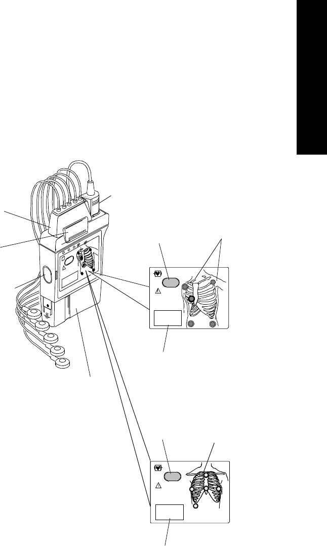
Agilent
Transmitters The Agilent Transmitter (EASI and standard ECG version) is battery powered
and worn by the patient. It acquires the patient’s ECG and SpO2 signals (if
available), processes them, and sends them via the antenna system to the
receiver. Measurements are then displayed at the Agilent Information Center.
The transmitter can also be connected via an infrared link to the Agilent Wave
Viewer to provide display of patient measurements and waveforms at the
patient’s side.
ECG Lead
Set
Connection
Combiner
Clip
Infrared Link to
the Agilent
Wave Viewer
Battery
Compartment
Transmitter
Label
Transmitter
Button
SpO2
Transducer
Connection
Chest Diagram
with LEADS
OFF Lights
Transmitter
Label
Transmitter
Button
EASI Chest
Diagram with
LEADS OFF
Lights
For
EASI
Transmitter
(label is
purple)
1
2
3
4
5
EASI
For Standard
ECG
Transmitter
(label is dark
green)
4
4

Transmitters
1-8 Introduction to the Agilent Telemetry System
ECG Connection: The Agilent Transmitter supports a 3- or 5-wire ECG cable
compatible with Agilent CMS/24 ECG trunk cables. The Agilent EASI
Transmitter supports 5-wire ECG cables only (use of a 3-wire cable set
generates an INOP condition). CMS trunk cables must include telemetry
combiners. In addition to keeping dirt out of the connectors, the combiner has a
locking mechanism to keep the lead set attached securely to the transmitter. For
safety, every lead should be secured to an electrode on the patient.
Warning Conductive parts of electrodes should not contact earth or other conductive
parts.
Disconnection of Leadset: When you’re ready to disconnect the leadset, lift
the clip of the combiner to release the lock. Then, holding the combiner firmly,
rock the leadset free. Do not pull on the lead wires or push on the combiner clip.
SpO2 Connection: In addition, both the standard ECG and EASI transmitter
support a SpO2 transducer (sensor) connection. SpO2 can be measured
continuously, intermittently at 1 or 5 minute intervals, or manually. Reusable
sensors in adult finger, small adult/pediatric finger, and ear clip models can be
used, as well as Oxisensor II™ disposable sensors. See Appendix B,
“Accessories and Ordering Information” for a list of sensors.
Chest Diagram & LEADS OFF Lights: The diagram on the front of the
standard ECG transmitter shows lead placement for a 5-wire lead set. The white,
black and red electrode positions represent standard AAMI 3-lead placement;
the red, yellow and green electrode positions represent standard IEC 3-lead
placement. Non-standard 3-wire lead placement diagrams are available at the
Agilent Wave Viewer.
The diagram on the front of the EASI transmitter shows EASI lead placement
for a 5-wire lead set. The AAMI colors that are used for EASI are brown (E),
red (A), black (S), white (I), and green (reference). The IEC equivalents for
EASI are white (E), green (A), yellow (S), red (I), and black (reference).
On both transmitters, each electrode position has a light that illuminates if the
corresponding electrode becomes detached. In a LEADS OFF situation, this
indicator will help you identify quickly which leads are off and re-attach them.
If the reference lead is off, after you correct the situation you may find other
lights illuminated as well.

Transmitters
Introduction to the Agilent Telemetry System 1-9
1 System Introduction
A second function of the Leads Off lights is to indicate successful power-up of
the transmitter. When you insert a battery into the transmitter, all five lights
should flash once. This indicates that the battery has adequate power for
monitoring and that there is no transmitter malfunction. See “Inserting Batteries”
on page 1-17 for details.
The electrode lights are also used as an indicator that a manual SpO2
measurement has been initiated at the transmitter.
Agilent
Telemetry
Battery
Extender
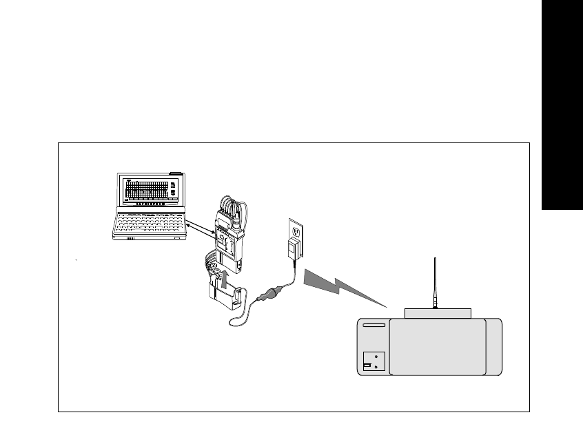
The Agilent Telemetry Battery Extender (M2611A) enables operation of the
transmitter with an external power source when a patient is not ambulating. The
battery extender can be used with Release B and C Agilent transmitters, and
earlier transmitters that have been upgraded.
The battery extender consists of a cradle, which is fitted over the battery
compartment of the transmitter, and a cable connecting to a wall-mounted DC
power module. When the battery extender is in use, no battery power is used
(battery save mode).
Note—
The purpose of the battery extender is to conserve battery life; the
extender does not recharge the battery.
Agilent Telemetry Battery Extender
Cradle Wire
Connector
Power Cable
Power
Module
Alignment
Groove
Cradle
Transmitters
1-10 Introduction to the Agilent Telemetry System
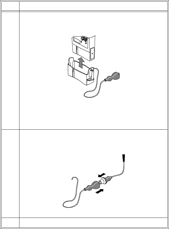
Connecting to the Battery Extender
To use a transmitter in battery-save mode, connect the transmitter to the battery
extender in the following steps:
Step Action
1 Align the grooves on the transmitter battery door and battery
extender cradle. Slip the cradle onto the base of the transmitter, and
press until you hear a click.
Note—
For accurate functioning, the battery cover must remain
closed when the extender is in use. In addition, Agilent
Technologies recommends that the battery remain in the transmitter
while the extender is in use.
2 Connect the aqua connector between the cradle wire and the power
cable. Be sure the connection is secure; the yellow band of the
connector should be completely covered.
3 Insert the power module into a wall power source.

Transmitters
Introduction to the Agilent Telemetry System 1-11
1 System Introduction
Disconnecting from the Battery Extender
To disconnect the transmitter from the battery extender for ambulatory
monitoring, perform the following steps:
Warning DO NOT UNPLUG THE POWER MODULE BEFORE REMOVING THE
CRADLE OR DISCONNECTING THE AQUA CONNECTOR.
If you unplug the power module before you disconnect the aqua connector
(or remove the cradle):
• The transmitter may reset automatically before switching to battery
power, making data unavailable at the Agilent Information Center
for a brief interval.
•Or, the transmitter may stop sending signals, and a NO SIGNAL
INOP will be displayed at the Agilent Information Center. In this
case, restart monitoring manually by removing and reinserting the
transmitter battery.
Step Action
1 Disconnect the aqua connector between the cradle wire and the
power cable.
Note—
The connector is designed to come apart on its own if the
patient gets up without disconnecting the connector.
2 Tuck the loose end of the cradle wire into the pouch.

Transmitters
1-12 Introduction to the Agilent Telemetry System
Transmitter
Features
Transmitter
Button The transmitter has a transmitter button (see page 1-7). Depending on how it is
configured, pressing this button produces:
• A “Nurse Call” message and tone
• A “Nurse Call” message and tone, plus a delayed recording
• A delayed recording
• No response at the Agilent Information Center.
Note—
Delayed recordings generated by the transmitter button are stored in
Alarm Review.
If desired, you can turn the transmitter button off for individual patients at the
Agilent Information Center by using the Telemetry Setup Window. See
“Turning the Transmitter Button On/Off” on page 2-10 for additional
information.
The transmitter button can also be used to initiate an SpO2 measurement. See
“Making SpO2 Measurements” on page 4-6 for more information.
Water
Resistance The transmitters and the battery extender (except the power module) can
withstand submersion in water for 5 minutes and exposure in a shower for 10
minutes. If the battery compartment gets wet, remove the battery and wipe the
compartment dry before monitoring. See “Chapter 7. Telemetry System
Cleaning” for details.
Caution
Disconnect the battery extender cradle from the power module prior to a
patient’s showering.
Earlier Agilent transmitters are also resistant to water. If either transmitter is
exposed to liquids, remove the battery and dry the battery compartment
thoroughly before monitoring.
If the transmitter or battery extender needs cleaning, follow the instructions in
“Cleaning the Transmitter & Battery Extender” on page 7-4.

Transmitters
Introduction to the Agilent Telemetry System 1-13
1 System Introduction
Pouch Use During normal use, the transmitter should be worn over clothing, in a pocket, or
preferably in a pouch.
Warning
Place the transmitter in a pouch or over clothing, or both, during patient
use. The transmitter should not touch the patient’s skin during normal use.
Automatic
Shutoff A service feature of the transmitter is RF Automatic Shutoff, which causes the
transmitter to stop broadcasting a radio signal if there is no ECG signal for 10
minutes. This prevents interference with other transmitters in use. The INOP
message at central is TRANSMITTER OFF. To restart monitoring, attach leads
to the patient. Automatic Shutoff can be configured off. When configured off,
batteries must be removed and the battery extender should be disconnected when
the transmitters are not in use to prevent RF interference and unnecessary
battery drain.
Battery
Information The Agilent Transmitter battery compartment is capable of accommodating any
type of standard 9 volt battery. An 8.4 volt Zinc-Air battery can be used with the
both the EASI ECG and standard ECG-only version of the transmitter. The
transmitter was not designed for use with rechargable batteries.
The battery compartment is located at the bottom of the transmitter. The length
of time the battery lasts depends on:
• The type of transmitter.
• The battery.
• The parameters being monitored - ECG only, ECG and continuous SpO2,
or ECG and intermittent SpO2.
When battery power is running low, the INOP message BATTERY WEAK
appears in the patient sector to indicate there is at least 15 minutes of battery life
remaining.
When there is no battery life remaining, the INOP message REPLACE
BATTERY is displayed.

Transmitters
1-14 Introduction to the Agilent Telemetry System
Note—
If the BATTERY WEAK message appears when you are making a STAT
SpO2 measurement, or changing the SpO2 sample rate out of Manual, it may be
necessary to replace the battery immediately in order to continue monitoring.
Be careful not to short circuit the battery. Short circuiting is caused when a piece
of metal touches both buttons (positive and negative terminals) at the top of the
battery simultaneously (for example, carrying batteries in a pocket with loose
change). More than a momentary short circuit will generally reduce the battery
life.
Warning
Certain failure conditions, such as extended short circuiting, can cause a
battery to overheat during normal use. High temperatures can cause burns
to the patient and/or user, or cause the battery to flame. If the transmitter
becomes hot to the touch, place it aside until it cools. Then remove the
battery and discard it. It’s a good idea to place a piece of tape across the
contacts of the battery to prevent inadvertent shorting. Have transmitter
operation checked by service to identify the cause of overheating.
The battery should be removed when the transmitter is stored.
Warning
Batteries should be removed from the transmitter at the end of the
battery’s useful life to prevent leakage.
Warning
If battery leakage should occur, use caution in removing the battery. Avoid
contact with skin. Clean the battery compartment according to instructions
in “Chapter 7. Telemetry System Cleaning”.
Use of Zinc-Air
Batteries Zinc-Air batteries can be used with ECG-only models of the transmitter,
revision A.01.02 and later. A Zinc-Air battery cannot be used with an ECG/
SpO2 transmitter.

Transmitters
Introduction to the Agilent Telemetry System 1-15
1 System Introduction
For maximum performance, observe the following guidelines:
• Use Zinc-Air batteries within 1 year of manufacture.
• Use Zinc-Air batteries within three months of opening the sealed package.
• Store and use Zinc-Air batteries at near room temperature. They can lose
50% of their capacity at low temperatures (0oC /32oF and below).
• Do not put Zinc-Air batteries in an environment with restricted air flow
(for example, a plastic bag). Serious restriction of air flow can affect
battery capacity. During normal use, the battery compartment provides
adequate air flow.
• Zinc-Air batteries may take up to one minute to get to working voltage
after they are removed from the airtight wrapper. You can hasten this by
shaking the battery.
Maximizing
Battery Life By observing the following guidelines, you can optimize battery life in the
Agilent transmitter:
• REMOVE THE BATTERY (or turn it over/up-end it) when the
transmitter is not in use.
Note—
Automatic Shutoff does not save battery life. In order to allow an
automatic turn-on, the transmitter ECG and SpO2 functions are not
completely disabled in this mode.
•For SpO
2 transmitters, when the SpO2 function is not in use, make sure
the SpO2 sample rate is set to Manual. See “Changing the SpO2 Sample
Rate” on page 6-10 for directions.
• Be sure to press End STAT at the end of every STAT SpO2 measurement
that is initiated at the Agilent Wave Viewer and wait for the red sensor
light to go out before removing the transducer.
Disposal of
Batteries Agilent Technologies recommends that you remove the battery when the
transmitter is not in use.
Caution
The battery must be removed if a transmitter will be stored for an extended
period of time.

Transmitters
1-16 Introduction to the Agilent Telemetry System
Important—
When disposing of batteries, follow local laws for proper disposal.
Dispose of batteries in approved containers. If local regulations require you to
recycle batteries, recycle batteries in accordance with regulations.
Nominal
Battery Life
Expectancy
1 Tested with Ultralife U9VL-J batteries.
2 Tested with Duracell MN1604 batteries.
3 Tested with Duracell DA146X batteries.
Recommended
Battery Types ECG Only ECG &
Continuous
SpO2
ECG &
Intermittent
SpO2
ECG with SpO2
Transducer
Detached
Lithium1
(supplied) 3 days 23 hours 23 hours 1 min. intervals:
1 day 21 hours
5 min. intervals:
3 days 3 hours
3 days
Alkaline2 1 day 18 hours 10 hours 1 min. intervals:
23 hours
5 min. intervals:
1 day 10 hours
1 day 10 hours
Zinc-Air34 days 18 hours Not Applicable Not Applicable Not Applicable
Transmitters
Introduction to the Agilent Telemetry System 1-17
1 System Introduction
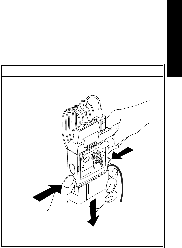
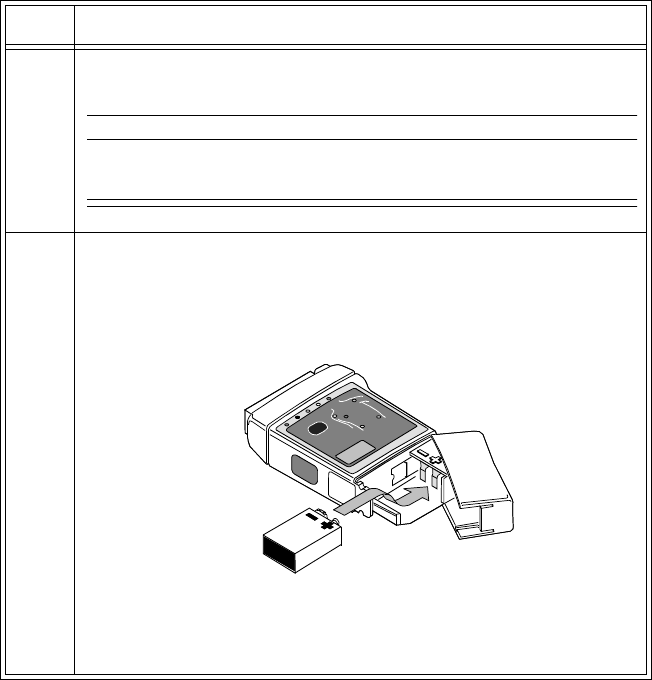
Inserting
Batteries Task Summary
Insert a battery into a transmitter by performing the following steps:
Step Action
1 Remove the battery extender, if present, by squeezing the tops of the
tabs (1) and sliding the cradle away from the transmitter (2).
1
1
2
1
1
2
1
Transmitters
1-18 Introduction to the Agilent Telemetry System
2 Open the battery compartment by pressing down on the
compartment door and swinging it 45° into an open hinged position.
Caution
Forcefully opening the compartment door to a full 90° will break the
hinges.
3 Insert the battery, matching the battery polarity with the +/-
indication inside the compartment.
Step Action

Transmitters
Introduction to the Agilent Telemetry System 1-19
1 System Introduction
4 When the battery is active after a few seconds, all five of the lights
on the chest diagram flash once, then each light flashes individually.
Next, if no leadset is attached, one light remains on, or if the
transmitter is connected to a patient, no lights remain on.
•If no lights flash, use a second new battery. If there are still no
lights, the transmitter memory may be corrupt. Contact
Service.
•If the lights come on but do not behave as described above,
the transmitter has malfunctioned. Contact Service.
IMPORTANT: When you replace the battery in a transmitter
connected to a patient, if either abnormal condition is in effect, no
monitoring will be occurring for the patient until either a new
battery or a replacement transmitter is used.
Step Action
Receiver Module
1-20 Introduction to the Agilent Telemetry System
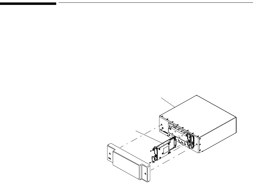
Receiver Module
The Agilent receiver modules are housed in the receiver mainframe. Each
receiver module is dedicated to a specific transmitter by an internal identity
code. This prevents another patient’s waveform from being erroneously
transmitted and displayed. The receiver acquires the ECG and SpO2 signals
from the transmitter and sends them to the receiver mainframe.
FRONT COVER
RECEIVER MODULE
RECEIVER MAINFRAME
Receiver Mainframe
Introduction to the Agilent Telemetry System 1-21
1 System Introduction
Receiver Mainframe
The Agilent receiver mainframe houses up to eight receiver modules. For each
receiver, the receiver mainframe calculates the heart rate, and sends the
waveform, alarms, inoperative messages (INOPs), and status messages over the
Agilent patient care system to the Agilent Information Center for display and
recording. If SpO2 is available, the transmitter processes the data and sends it to
the Agilent Information Center via the network as well.
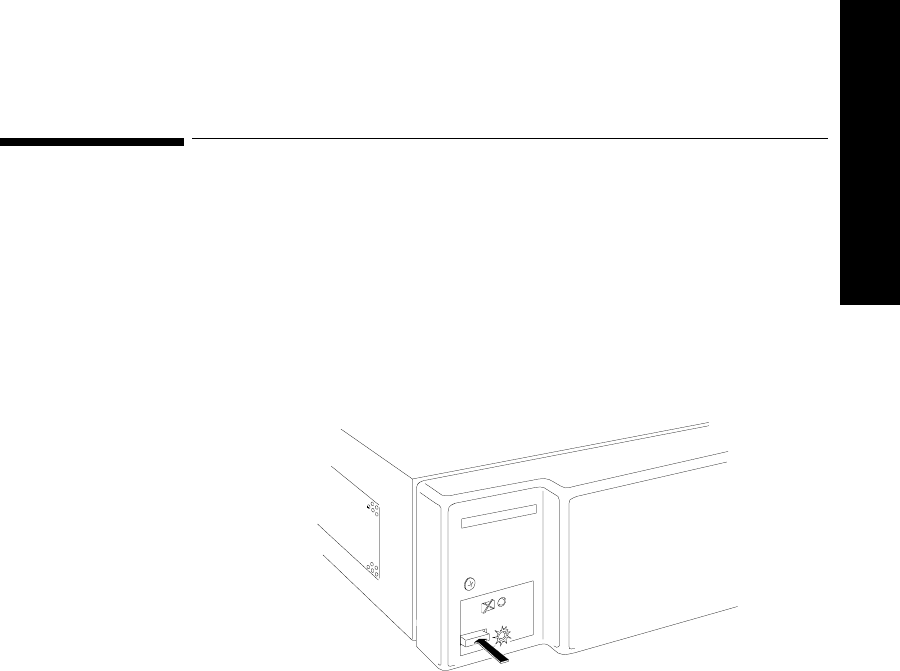
Turning the
Receiver
Mainframe On
or Off
The receiver mainframe must be turned on for individual transmitters and
receivers to work. To turn the receiver mainframe on, press the button on the
lower left corner of the front of the mainframe. A green light illuminates to
signify the mainframe and all the receivers are on.
If the receiver mainframe is turned off, the light and all receiver modules are off.
Receiver
Mainframe
Malfunction
Light
A red light on the front panel of the mainframe illuminates when either the
mainframe or one of the receivers has malfunctioned. Depending on the
problem, you may see the message, NO DATA FROM BED, in single or
multiple patient sectors. Contact your Agilent Technologies Service
Representative.
.
PRESS POWER BUTTON
TO TURN ON
PRESS AGAIN TO TURN OFF

Antenna System
1-22 Introduction to the Agilent Telemetry System
When the mainframe is first turned on, the red light flashes. If no problems are
detected, the flashing stops and the light turns off.
Channel
Frequencies The frequency of Agilent transmitters and receivers are programmable, thus
enabling changes in frequency if interference is detected. In case of interference,
contact service.
Retaining
Telemetry
Settings
If power to the receiver mainframe is interrupted or turned off, settings
controlled by the mainframe such as leads may be affected.
• If the receiver mainframe is turned off for less than three hours, your
settings should still be in effect.
• If the mainframe is turned off for more than three hours, your settings
revert to default, that is, to the configured settings at installation.
Antenna System
The telemetry antenna system is custom-designed for your unit to ensure
adequate coverage, therefore the telemetry signal can only be received where
there are receiving antennas. After it is received by the antenna system, it is sent
to the receiver which recovers the patient's ECG and optional SpO2. This
information is then sent to a monitoring display.

Turning Telemetry On/Off
Introduction to the Agilent Telemetry System 1-23
1 System Introduction
Turning Telemetry On/Off
Telemetry monitoring can be turned on or off in one of several ways:
• Manually, by activating Monitoring Standby at the Agilent Information
Center (click on Patient Window, then Standby). This action creates a
TELEMETRY STANDBY message on the display. To restart monitoring,
click on Resume Monitoring in the Patient Sector.
• Automatically, if Auto Shutoff is enabled at the transmitter and if there is
no ECG signal for 10 minutes. This situation creates a TRANSMITTER
OFF inop at central. To restart monitoring, re-attach the lead wires.
• Manually, by removing the transmitter battery. This action creates a NO
SIGNAL inop at central. To restart, insert the battery.
Turning Telemetry On/Off
1-24 Introduction to the Agilent Telemetry System

ECG Monitoring 2-1
2 ECG Monitoring
2
ECG Monitoring
This chapter provides information on setting up and managing ECG monitoring.
It includes the following sections:
• Lead Sets & Capabilities. . . . . . . . . . . . . . . . . . . . . . . . . . . . . . . . . . . . 2-2
• Preparing for ECG Telemetry Monitoring . . . . . . . . . . . . . . . . . . . . . .2-5
• EASI 12-lead Monitoring . . . . . . . . . . . . . . . . . . . . . . . . . . . . . . . . . . .2-6
• Making Other Monitoring Adjustments . . . . . . . . . . . . . . . . . . . . . . .2-10
• Monitoring During Leads Off . . . . . . . . . . . . . . . . . . . . . . . . . . . . . . .2-12
• Optimizing System Performance . . . . . . . . . . . . . . . . . . . . . . . . . . . .2-14
• ECG Alarm Summary. . . . . . . . . . . . . . . . . . . . . . . . . . . . . . . . . . . . .2-18
• Telemetry Alarm & INOP Summary . . . . . . . . . . . . . . . . . . . . . . . . .2-18

Lead Sets & Capabilities
2-2 ECG Monitoring
Lead Sets & Capabilities
Standard
ECG
Transmitter
The standard ECG Transmitter supports 3- and 5-wire cables. The table below
provides a summary of the capabilities of each cable.
Note—
For details of electrode placement, see the Agilent Information Center
Online Help. For 3-wire electrode placement with Lead Select turned off, see
also the Agilent Wave Viewer Help.
Lead
Set Number
of Leads Lead/Label Choices
3-wire
-Lead
Select
Off
1• Position electrodes for desired
lead. Standard placement gives
Lead II.
See the on-line help in the
Wave Viewer for information
on electrode placement.
• Select Label to match
electrode placement.
Warning—Agilent Technologies
recommends you change the lead
label only to reflect the physical
placement of the electrodes. This
ensures that the monitored lead
and the label match, and
prevents any possible confusion.
Primary
I, II, III, MCL
Secondary
Not available

Lead Sets & Capabilities
ECG Monitoring 2-3
2 ECG Monitoring
3-wire
-Lead
Select
On
1• Position electrodes in standard
placement.
• Use the Wave Viewer to
change the lead that is
transmitted to the Agilent
Information Center (see
“Changing the Lead (Standard
ECG only)” on page 6-7).
Lead selection at the Agilent
Information Center is disabled.
Primary
I, II, III
Secondary
Not available
5-wire 2 • Position electrodes in standard
placement.
Standard placement provides
V1 or MCL1. To monitor a
different chest lead, for
example, V6 or MCL6,
position chest electrode
appropriately.
• Select Lead.
Primary
I, II, III, aVL,
aVR, aVF, V,
MCL
Secondary
I, II, III, aVL,
aVR, aVF, V,
MCL
Lead
Set Number
of Leads Lead/Label Choices

Lead Sets & Capabilities
2-4 ECG Monitoring
Agilent EASI
Tr ansm i tter The Agilent EASI Transmitter supports 5-wire cables. The table below provides
a summary of this cable’s capabilities.
Note—
For details of EASI electrode placement, see the Agilent Information
Center Online Help. .
1
2
3
4
5
EASI
Lead
Set Number
of Leads Lead/Label Choices
5-wire 2 • Position electrodes in EASI.
placement.
EASI placement provides a
derived Lead II for overview.
•Click 12-Lead ECG to display
a 2.5 second ECG wave of
each of the 12 derived leads.
If there is an INOP condition
in any lead, it is not possible to
display the 12-lead waves.
Note—
With EASI, although you
can view and do ST
analysis on all 12 derived
leads, arrhythmia
monitoring can only be
done on 2 leads.
•Click 3 EASI Leads to view
the AI, AS, and ES leads and
troubleshoot ECG waveform
quality problems.
Primary
I, II, III, aVL,
aVR, aVF, V1,
V2, V3, V4,
V5, V6
Secondary
I, II, III, aVL,
aVR, aVF, V1,
V2, V3, V4,
V5, V6

Preparing for ECG Telemetry Monitoring
ECG Monitoring 2-5
2 ECG Monitoring
Preparing for ECG Telemetry Monitoring
Overview The Agilent Telemetry System provides remote monitoring of the patient’s ECG
for adult and pediatric patients.
Note—
For SpO2 setup, see Chapter 4, “SpO2 Monitoring”
Task
Summary Perform the following steps to set up for telemetry ECG monitoring:
Step Action
1 Insert a battery into the transmitter, following the +/- diagram on the
inside of the compartment. See “Inserting Batteries” on page 1-17.
2 Connect the lead set to the transmitter by pushing it down firmly
until it “locks.” You should hear a click.
3 Prepare the skin by:
1. Shaving the hair from electrode sites if necessary.
2. Washing the sites (preferably with soap and water), and rinsing
well.
3. Drying briskly to remove skin cells and oils.
4 Attach the electrodes to the lead wires.
Note—
Use electrodes that are all the same brand and change all the
electrodes every 24 hours.
5 Remove electrode backing and check for moist gel.
6Apply electrodes to the skin by placing the edge down, then “rolling
down” the rest of the pad. Press firmly around the adhesive edge
toward the center. See the on-line help for information on electrode
placement. Or, for 3-wire cables only with Lead Select off, see the
Agilent Wave Viewer ECG screen for lead placement information.
See“Viewing Other Standard ECG Leads” on page 6-5.

Preparing for ECG Telemetry Monitoring
2-6 ECG Monitoring
During monitoring, respond promptly to INOP conditions to prevent loss of
monitoring.
EASI
12-lead
Monitoring
EASI 12-lead ECG monitoring (for use only on adult and pediatric patients)
allows you to derive all 12 standard ECG leads, using a 5-wire electrode cable
and special electrode placement (see the online Help on the Agilent Information
Center for lead placement information or refer to the diagram in Appendix C).
EASI monitoring also enables the monitoring of ST changes with a full 12-lead
ECG.
When using EASI monitoring,
• Any telemetry EASI bed must be arrhythmia-monitored. If arrhythmia is
not on, the INOP “ARRHY REQUIRED” is shown and no waves or
parameters are displayed.
• When placing electrodes, be careful to place the electrodes as accurately
as possible or the derived leads may be incorrect. If necessary, the AI
electrodes may be shifted down or up , or the ES electrodes may be
shifted left or right, but the AI and ES electrodes must still be at right
angles. The following guidelines should be followed:
7 Verify the lead placement using the Agilent Wave Viewer. See
“Checking ECG Signal Quality” on page 6-4.
8 Support the transmitter by using a pouch, and if necessary, tape the
lead wires to the chest.
9 Teach the patient how and when to press the transmitter button.
10 Make adjustments to ECG wave(s) and alarm limits in the Patient
Window. See “Making ECG Adjustments” on page 2-8.
11 If using EASI, turn arrhythmia monitoring on for this patient. See
the Agilent Information Center User Guide for instructions. Refer to
the next section for additional information on EASI monitoring.
Step Action
1
2
3
4
5
EASI

Preparing for ECG Telemetry Monitoring
ECG Monitoring 2-7
2 ECG Monitoring
–When plaster or therapeutic equipment restricts electrode
placement, the E and S electrodes can be moved in parallel to the
patient’s right, but keep this move as small as possible.
–When pulmonary problems restrict electrode placement, the A and I
electrodes can be moved down or up in parallel. Moving the
electrodes down produces better measurements than moving them
up.

Making ECG Adjustments
2-8 ECG Monitoring
Making ECG Adjustments
Overview You can make the following adjustments from the Agilent Information Center:
• Change the lead or the lead label.
• Change the wave size.
With 5-wire lead sets, you can monitor two leads. With a 3-wire lead set you can
monitor one lead. When monitoring two leads, the first lead is the primary lead.
Single lead arrhythmia analysis uses this lead. It is also the lead used for alarm
and delayed recordings. Multilead analysis uses both leads.
If you are not receiving a good ECG wave and the electrodes are securely
attached, you should try changing the lead in which you are monitoring.
Bandwidth Bandwidth is not user adjustable, but is assigned automatically by the
information center. The settings are:
Changing
Lead/Label To change the lead/label place your cursor over the wave in the Patient Window
and select the lead or label from the pop-up box to match the placement.
Adjusting
Wave Size To change the amplitude of the ECG wave on the display or for recordings,
place your cursor over the wave in the Patient Window and select the size you
want from the pop-up box. There are five sizes available: 1/4 (smallest), 1/2, 1,
2, and 4 (largest).
Setting Bandwidth
ST off Monitor (0-40 Hz)
ST on ST (0.05 to 40 Hz)
Making ECG Adjustments
ECG Monitoring 2-9
2 ECG Monitoring
You can use the 1 mV cal bar on the Patient Window to check the height of the
R-wave. If the wave is not at least 0.5 mV high (one-half the size of the cal bar),
change the lead.
0.5 mV
1 mV

Making Other Monitoring Adjustments
2-10 ECG Monitoring
Making Other Monitoring Adjustments
Turning the Transmitter Button On/Off
Overview You can turn the Transmitter Button on the transmitter on or off by using the
Telemetry Setup Window. Turning the Transmitter Button off inhibits Nurse
Call alarms and/or recordings depending on how your system is set up.
Task Summary Turn the Transmitter Button on the transmitter on or off by performing the
following steps:
Note—
Manual SpO2 measurements can still be made using the transmitter
button even when the button is turned off at the central. See “Making SpO2
Measurements” on page 4-6.
Step Action
1 On the Patient Window click the All Controls button.
2 On the All Controls Window click the Telemetry Setup button.
3 On the Telemetry Setup Window turn the Transmitter Button on or
off by clicking in the Transmitter Button Allow Calls checkbox. A
check mark in the checkbox indicates that the transmitter button is
on.

Making Other Monitoring Adjustments
ECG Monitoring 2-11
2 ECG Monitoring
Standby
Mode When a patient is temporarily off the unit or out of antenna range you can
suspend monitoring by placing telemetry in Standby Mode. Standby suspends
monitoring, and you won’t get any waveforms or alarms.
If a patient leaves the unit without a transmitter, place telemetry in Standby.
Note—
If you remove the leads before putting a patient into Standby, you’ll get a
LEADS OFF INOP, and reminders if configured.
Warning
If you put telemetry in Standby Mode, you must remember to turn
monitoring back on when the patient returns to the unit.
Note—
When you take an EASI transmitter out of Standby, the lead settings
revert back to the central’s default lead settings (i.e., II and V2).
Task Summary Place a patient in Standby by performing the following steps:
Step Action
1 On the Patient Window click the Standby button.
2Select the patient’s location from the pre-defined list.
3 Click the Suspend Monitoring button. This indefinitely suspends
all monitoring and displays the following messages in the Patient
Sector “NO DATA FROM BED” and “TELEMETRY
STANDBY” and the location (for example, X-Ray).
Note—
Be sure to take the bed out of Standby before discharging.
Since Standby is associated with the equipment assigned to a
bed, if a patient is discharged and the bed is in Standby Mode,
that equipment will be in Standby for the next patient, and
monitoring will continue to be interrupted.
4 When the patient comes back, restart monitoring by clicking on
Resume Monitoring in the Patient Sector.

Monitoring During Leads Off
2-12 ECG Monitoring
Monitoring During Leads Off
Fallback
Multilead
Analysis If there is a Leads Off INOP in the primary lead for >10 seconds, the active
secondary lead becomes the primary lead. This is known as lead fallback. In lead
fallback, the arrhythmia system switches the leads on the display. When the
Leads Off condition is corrected, the leads are switched back.
Singlelead
Analysis For single lead analysis, if there are two leads available, the other lead is made
the primary lead (until the Leads Off condition is corrected).
Fallback for
EASI If one of the derived EASI leads has an INOP condition (for example, LEADS
OFF), a flat line is displayed. After ten seconds, the directly acquired EASI AI,
AS, or ES lead (depending on which is available) is displayed with the label
“ECG” and is analyzed by the arrhythmia system.
• Whenever there is an INOP condition (i.e., LEADS OFF), the arrhythmia
algorithm performs a Relearn, using the available leads.
Warning Since Relearn happens automatically, if learning takes place during
ventricular rhythm, the ectopics may be incorrectly learned as the normal
QRS complex. This may result in missed detection of subsequent events of
V-Tach and V-Fib. For this reason, you should:
1. Respond promptly to the INOP message (for example, re-connect
the electrode(s).
2. Ensure that the arrhythmia algorithm is labeling beats correctly.
Note—
If there is artifact in the ECG waves or a CANNOT ANALYZE ECG
INOP condition, you can use the three EASI leads to troubleshoot.
Click 12-Lead ECG on the Patient Window, then on 3 EASI Leads.
1
2
3
4
5
EASI

Monitoring During Leads Off
ECG Monitoring 2-13
2 ECG Monitoring
2. The three directly acquired EASI leads will be displayed so that you can
determine which electrodes are causing the problem and need to be
replaced.
Extended
Monitoring When both the primary and secondary leads have a Leads Off condition, if
another lead is available it becomes the primary lead and the system does a
relearn. This is called extended monitoring.
Extended monitoring applies if:
• Telemetry is configured for extended monitoring ON.
• The leadset provides more than two leads (i.e., when using a 5-wire
leadset).

Optimizing System Performance
2-14 ECG Monitoring
Optimizing System Performance
While telemetry monitoring offers many advantages, it can be a challenge. The
reliability and quality of the signal transmission through the air and hospital
walls is governed by a number of variables which can be difficult to control. A
telemetry system cannot be as dependable as a hardwired bedside monitor that
transmits its signal through a wire.
The effect of interference on the telemetry system ranges from a momentary loss
of ECG to complete inoperability, depending on the situation. The strength,
frequency, and proximity of the source of interference to transmitters or the
antenna system are factors that determine the degree of severity. In cases where
the source of interference is known - for example, cellular phones, magnetic
equipment such as MRI, other radio or motorized equipment - removing or
moving away from the source of interference will increase the system’s
dependability.
Warning
Telemetry should not be used for primary monitoring in applications where
the momentary loss of the ECG is unacceptable.
In this section, we’ll investigate some of the problems affecting ECG signal
clarity and when possible, show you how you can greatly enhance performance.
Note—
The telemetry system also emits radio frequencies (defined in “System
Specifications” on page 9-20) that may affect the operation of other devices.
Contact the manufacturer of other equipment for possible susceptibility to these
frequencies.
The
Telemetry
Signal
The transmitter worn by the patient acquires the patient's physiological data,
amplifies and digitizes it, detects pace pulses and broadcasts this information via
radio waves to the antenna system. Since the signal passes through the air, it is
susceptible to interference from many sources.
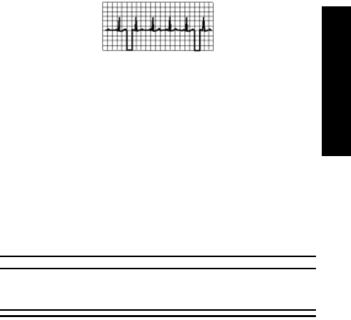
Optimizing System Performance
ECG Monitoring 2-15
2 ECG Monitoring
Frequent
Signal
Strength
and RF
INOPs
Because the telemetry system is a wireless system, under certain conditions RF
“dropouts” can occur. Dropouts result from a weak signal or RF interference.
There will be signal drops to the bottom of channel for a minimum of 200 ms to
indicate to the clinical user that it is a non-physiological event. If dropouts are
frequent enough to affect the heart rate count, the TEL CANNOT ANALYZE
INOP occurs. The following recording strip is an example of dropouts.
If frequent dropouts are occurring, the following section describes some steps
you can take to improve performance.
Signal
Strength The antenna system is custom designed for your unit, so reliable signal reception
is only possible where there are receiving antennas. When the signal is too low,
the following INOPS occur:
• TEL CANNOT ANALYZE
• WEAK SIGNAL
• NO SIGNAL
To correct, first check the location of the patient. If not in the coverage area, do
one of the following.
• Return the patient to the specified antenna coverage area.
• Put telemetry in Standby Mode. See “Standby Mode” on page 2-11.
Warning
If you put telemetry in Standby Mode, you must remember to turn
monitoring back on when the patient returns to the unit. See “Standby
Mode” on page 2-11.
• If the patient is in the coverage area and is stationary, try moving the
location of the transmitter or patient about six inches.

Optimizing System Performance
2-16 ECG Monitoring
Radio
Frequency
Interference
Radio frequency (RF) interference is caused by anything that intrudes into the
transmitted electrical signal, such as paging transmitters and walkie-talkies. We
are all familiar with electrical interference in our homes and cars when it causes
“snow” on the television and static on the radio station. These same types of
interference can occur with the transmitted telemetry signal. Even though the
Agilent Telemetry System is designed to resist these effects, interference can
occasionally be seen in the form of “dropouts”. To improve performance, the
source of the interference must be identified and eliminated.
Muscle and
Movement
Artifact
Muscle and movement artifact differ from radio frequency interference since
you can prevent much of the occurrence. Noise on the ECG signal can be caused
by many sources, such as interference from other electrical equipment, muscle
artifact and respiration variation. It is up to the clinician to use certain
techniques to minimize these types of noise. Use the following table to help you
troubleshoot the most common sources of ECG noise.
Problem Cause Remedy
60-Cycle (AC)
Interference Poor electrode
placement.
Possible non-grounded
instrument near patient
Re-apply electrodes
Disconnect electrical appliances near
patient (one at a time) by pulling wall
plugs, to determine faulty grounding.
Have engineering check grounding.
Muscle Artifact Tense, uncomfortable
patient.
Poor electrode
placement.
Tremors.
Diaphoresis
Make sure patient is comfortable.
Check that electrodes are applied on flat
non-muscular areas of the torso; dry the
skin and re-apply the electrodes if
necessary.
Irregular Baseline Poor electrical contact.
Respiratory interference.
Faulty electrodes.
Dry electrodes.
Re-apply electrodes, using proper
technique.
Move electrodes away from areas with
greatest movement during respiration.

Optimizing System Performance
ECG Monitoring 2-17
2 ECG Monitoring
Baseline Wander Movement of patient.
Improperly applied
electrodes.
Respiratory interference.
Make sure patient is comfortable.
Re-apply electrodes. Check that patient
cable is not pulling electrodes.
Move electrodes away from areas with
greatest movement during respiration.
Poor Electrode Contact Loose electrodes.
Defective cables.
Lead set not firmly
connected.
Change electrodes, using good skin prep.
Replace cables.
Problem Cause Remedy

ECG Alarm Summary
2-18 ECG Monitoring
ECG Alarm Summary
The following table lists the ECG alarms that can be generated by the Telemetry
System when using the standard ECG transmitter. These are announced at the
Agilent Information Center when arrhythmia monitoring is turned off at central.
Note—
When arrhythmia monitoring is turned on at central, ECG alarms are
generated by the ST/AR algorithm. Please refer to the Agilent Information
Center User Guide for information about these alarms.
Telemetry Alarm & INOP Summary
There is one non-parameter alarm in the Telemetry System.
Alarm Message Alarm Level Audible
Indication Description
***ASYSTOLE Cardiotach alarm *** Sound No QRS in 4 seconds
***VENT FIB Cardiotach alarm *** Sound Ventricular Fibrillation
** HR > upper limit Cardiotach alarm ** Sound HR greater than the
upper heart rate limit
** HR < lower limit Cardiotach alarm ** Sound HR less than the lower
heart rate limit
Alarm Message Alarm Level Audible
Indication Description
** NURSE CALL Manual -
Telemetry System ** Sound
(short) Patient-generated alarm
(at transmitter button).
Must be configured on.

Telemetry Alarm & INOP Summary
ECG Monitoring 2-19
2 ECG Monitoring
The following table lists (in alphabetical order) the telemetry INOPs that can be
announced at the Agilent Information Center. It also provides suggestions on
what to do when an INOP occurs.
Note—
A Hard INOP is more severe than a soft INOP. Hard INOPS have an
audible tone, and monitoring and alarms are disabled. In a soft INOP, no audible
tone is generated; monitoring and alarms remain active.
Message Type Description Action
ARRHY REQUIRED Hard INOP Arrhythmia monitoring was
turned off for an EASI
transmitter.
Turn arrhythmia monitoring
on or change to a standard
ECG transmitter if
arrhythmia monitoring is not
desired.
BATTERY WEAK Soft INOP Battery low, at least 15
minutes left.
Note—
Certain transient
conditions such as manual
SpO2 measurement, unaligned
transmitter, or heavy infrared
use may cause battery weak
situation.
Replace battery.
ECG EQUIP MALF Hard INOP ECG PC board in the
transmitter is malfunctioning
An EASI transmitter is being
used with equipment that is
not capable of accepting EASI
data (pre-release C), creating a
software incompatibility.
Replace transmitter. Contact
Service.
Contact Service.

Telemetry Alarm & INOP Summary
2-20 ECG Monitoring
INTERFERENCE Hard INOP Interference due to outside
source. Check that there are no
transmitters stored with
batteries inserted.
Change the Agilent
transmitter and receiver
frequency.
Contact service.
INVALID LEADSET Hard INOP Leadset is connected
improperly, or an invalid
leadset is being used for the
transmitter type and is
connected to the patient (e.g.,
EASI transmitter must use a 5-
wire leadset.)
Reconnect leadset, pressing
until latch clicks.
Attach correct leadset.
If problem persists, call
service.
INVALID SIGNAL
E01 Hard INOP Receiver is picking up a
duplicate frequency. When the transmitter is not
being used, turn telemetry
monitoring off for the bed.
If the situation continues,
contact service.
If this is a new transmitter,
the system must learn the
new transmitter ID code -
contact service.
LEADS OFF Hard INOP Lead(s) not connected. Reconnect lead(s). Use
transmitter lights or the
Agilent Wave Viewer to
confirm.
NO RECEIVER Hard INOP Receiver absent or
malfunctioning. This message appears after
the mainframe is turned on
and indicates the absence of
a receiver or a receiver is
faulty. Contact service.
Message Type Description Action

Telemetry Alarm & INOP Summary
ECG Monitoring 2-21
2 ECG Monitoring
NO SIGNAL Hard INOP Patient beyond antenna range,
no battery, battery is inserted
backwards, or battery extender
is unplugged.
Return patient to antenna
range/check battery for
correct insertion/remove and
reinsert battery.
RECEIVER MALF Hard INOP Receiver is malfunctioning. Contact service.
REPLACE
BATTERY Hard INOP Battery is unable to power the
transmitter, or battery is
inserted backwards.
Replace battery/check
battery for correct insertion.
##nnn/nnn(nnn)nnn
(RF INOP) Soft INOP Used by service in
troubleshooting the radio
signal.
Contact service.
TEL CANNOT
ANALYZE Hard INOP Shorts bursts of data
corruption inhibiting an
accurate HR count. (Often
accompanied by WEAK
SIGNAL, NO SIGNAL, or
INTERFERENCE INOPs.)
Check that there are no
transmitters stored with
batteries.
Check to see if the patient is
in the coverage area, and
return patient if needed.
If the patient is in the
coverage area and is
stationary, move the
transmitter or patient about
6 inches (15 cm.).
If the situation persists,
contact service.
TRANSMITTER
MALF Hard INOP Transmitter malfunctioning Replace transmitter.
Contact service.
Message Type Description Action

Telemetry Alarm & INOP Summary
2-22 ECG Monitoring
TRANSMITTER
OFF Hard INOP Transmitter detected all leads
off for 10 minutes and turned
itself off.
Connect leadset to patient.
WEAK SIGNAL Soft INOP Patient at outer range of the
antenna system. Check to see if the patient is
in the coverage area, and
return patient if needed.
If the patient is in the
coverage area and is
stationary, move the
transmitter or patient about
6 inches (15 cm.).
If the situation persists,
contact service.
Message Type Description Action

ST/AR ST Segment Monitoring 3-1
3 ST Monitoring
3
ST/AR ST Segment Monitoring
This chapter describes the ST/AR ST algorithm for telemetry of the Agilent
Information Center. It includes the following sections:
• ST/AR ST Algorithm . . . . . . . . . . . . . . . . . . . . . . . . . . . . . . . . . . . . . .3-2
• Adjusting Measurement Points . . . . . . . . . . . . . . . . . . . . . . . . . . . . . . .3-5
• Establishing ST Reference Beats (Baseline). . . . . . . . . . . . . . . . . . . . . 3-6
• Turning ST On/Off . . . . . . . . . . . . . . . . . . . . . . . . . . . . . . . . . . . . . . . .3-7
• ST Alarms . . . . . . . . . . . . . . . . . . . . . . . . . . . . . . . . . . . . . . . . . . . . . . . 3-8

ST/AR ST Algorithm
3-2 ST/AR ST Segment Monitoring
ST/AR ST Algorithm
Intended
Use The intended use of the ST/AR ST algorithm for M3150A Agilent Information
Center Server (not available for M3153A) is to monitor ST segment elevation or
depression for each available telemetry ECG lead and produce events/alarms
simultaneously. ST values update with every measurement period and enunciate,
depending upon the severity of the change, events and alarms as they are
detected.
Patient
Population You can perform ST analysis on both non-paced and atrially paced patients. The
ST/AR ST algorithm is only available for adult telemetry-monitored patients.
With EASI monitoring, ST analysis is performed on up to 12 leads.
Note—
Studies have validated the maximal EASI derived ST measurements on
male and female patients with ages from 33 to 82, heights 147 to 185 cm (58 to
73 in), weights 53 to 118 kg (117 to 261 lb) and height-to-weight ratios of 1.41
to 2.99 cm/kg (0.25 to 0.54 in/lb).
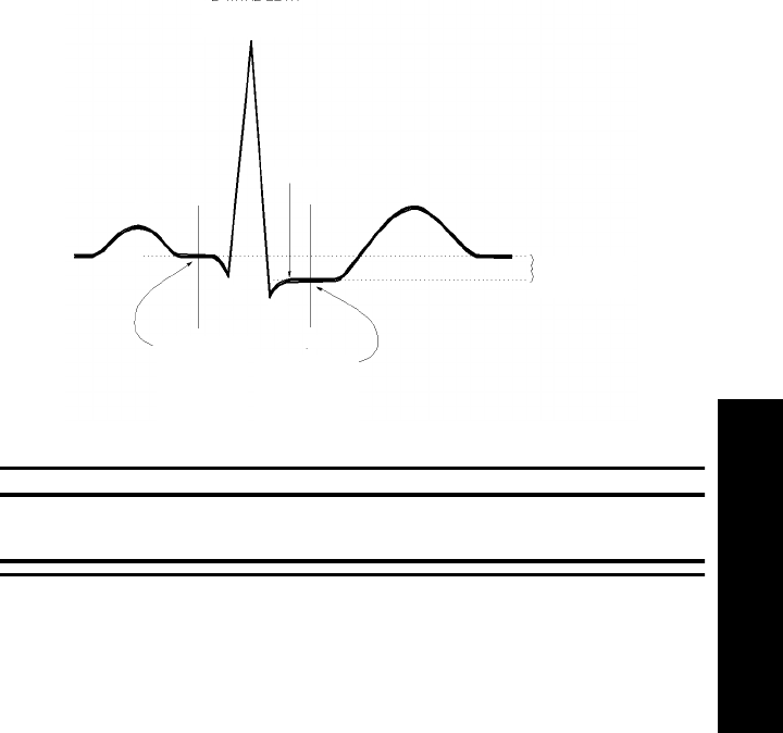
ST/AR ST Algorithm
ST/AR ST Segment Monitoring 3-3
3 ST Monitoring
The
Measurement The ST measurement for each beat complex is the vertical difference between
two measurement points. The isoelectric point provides the baseline for the
measurement and the ST point provides the other measurement point. It is
positioned with reference to the J-point.
Warning
This device provides ST level change information; the clinical significance
of the ST level change information should be determined by a physician.
R-WAVE PEAK
AT 0 MSEC
J POINT
ISO ELECTRIC
POINT
DEFAULT =
-80 MSEC
MEASUREMENT
POINT
DEFAULT =
J+60 MSEC
DIFFERENCE =
ST VALUE
P
Q
S
ST
T

ST/AR ST Algorithm
3-4 ST/AR ST Segment Monitoring
How the
Algorithm
Works
When ST analysis is being performed on two leads, the averaged derived and
reconstructed ST waves and associated ST segment values are given for up to
six leads, depending on the type of patient cable:
• 3-wire: one lead
• 5-wire: up to two leads if monitoring a chest and a limb lead
• 5-wire: up to six leads if monitoring two limb leads with the Agilent
Transmitter (without EASI monitoring)
• 5- wire: up to 12 leads if monitoring using EASI
Note—
No ST analysis is done on a patient if an electrode falls off.
ST analysis uses the ST/AR arrhythmia beat classification to select only normal
and atrially paced beats for its analysis.
The ST/AR ST algorithm processing includes special ST filtering, beat selection
and statistical analysis, calculation of ST segment elevations and depressions,
and lead reconstruction and wave generation.
Displayed
ST Data ST data displays as values in the Patient Sector and Patient Window. A positive
value indicates ST segment elevation; a negative value indicates depression.
You can view ST data in ST Review, Trend Review, and Event Review
windows.
EASI ST
Analysis ST/AR ST analysis for EASI derived transmitters is done on all 12 leads. The
value presented in the patient sector and Patient Window is “STindx”. STindx is
a summation of three ST segment measurements, using the leads that can
indicate ST segment changes in the different locations of the heart:
• anterior lead V2
• lateral lead V5
• inferior lead aVF
Caution
Be sure not to duplicate the lead labels. This can result in incorrect ST values
being displayed for those leads.
1
2
3
4
5
EASI
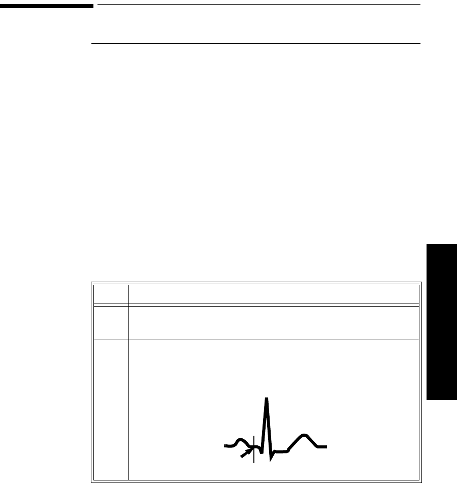
Adjusting Measurement Points
ST/AR ST Segment Monitoring 3-5
3 ST Monitoring
Adjusting Measurement Points
Overview The ST Setup Window allows you to adjust the ST measurement points to
ensure accurate data.
There are three measurement cursors:
• The ISO measurement cursor positions the isoelectric point in relation to
the R-wave peak.
• The J-point cursor positions the J-point in relation to the R-wave peak.
The purpose of the J-point is to correctly position the ST measurement
point.
• The ST measurement cursor positions the ST point a fixed distance from
the J point.
Note—
The ST measurement points may need to be adjusted if the patient’s heart
rate or ECG morphology changes significantly.
Task
Summary Perform the following steps to adjust the ST measurement points:
Step Action
1 Access the ST Setup window by clicking on the All Controls button
in the Patient Window then clicking on the ST Setup button.
2 If you need to adjust the ISO (isoelectric) point, position the bar in
the middle of the flattest part of the baseline (between the P and Q
waves or in front of the P wave) and use the arrow keys to make the
adjustment.
T
R
P
ISO
POINT QS
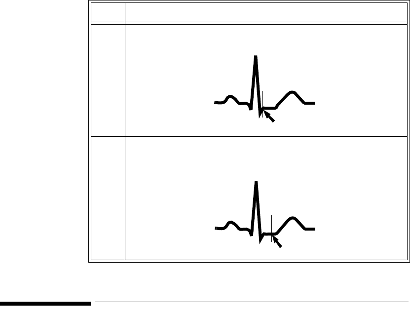
Establishing ST Reference Beats (Baseline)
3-6 ST/AR ST Segment Monitoring
Establishing ST Reference Beats (Baseline)
After adjusting the measurement points, you can establish baseline reference
beats for all available leads in the ST Review window at the Agilent Information
Center. Reference beats enable you to compare waveform changes, for example
from admission, or prior to or after treatment. The reference continues to be
saved beyond the 24 hour review window, but you can update it to any beat
within the last 24 hours. Please refer to the Agilent Information Center User’s
Guide or on-line Help for directions.
3 Adjust the J point, if necessary, by positioning the bar at the end of
the QRS complex and the beginning of the ST segment.
4 Adjust the ST point, if necessary, by using the J point as an
“anchor” and using either J + 60 or J + 80 so that the bar is at the
midpoint of the ST segment.
Step Action
T
R
P
S
QJ POINT
T
R
P
S
QST POINT

Turning ST On/Off
ST/AR ST Segment Monitoring 3-7
3 ST Monitoring
Turning ST On/Off
Overview The ST Setup Window allows you to turn ST monitoring on/off for individual or
all ECG leads. You would turn ST monitoring off if:
• You are unable to get any lead that is not noisy.
• Arrhythmias such as atrial fib/flutter cause irregular baseline.
• The patient is continuously ventricularly paced.
• The patient has left bundle branch block.
Task
Summary To turn ST monitoring on/off perform the following steps:
Step Action
1 Access the ST Setup Window by clicking the All Controls button on
the Patient Window then clicking the ST Setup button.
2 If you want to turn all ST monitoring on/off click the All On or All
Off button respectively.
3 Turn on/off individual leads by clicking on the check box to the left
of the lead. A check mark in the box indicates that monitoring is on.

ST Alarms
3-8 ST/AR ST Segment Monitoring
ST Alarms
Overview All Agilent Information Center alarm settings (limits and on/off status) have unit
default settings. The Agilent Information Center however, lets you set the high
and low ST alarm limits for individual patients based on:
• Your assessment of the patient's clinical condition.
• Unit protocols.
• Physician orders or medication specified limits.
You can make the following adjustments to ST alarm limits to accommodate the
clinical condition of individual patients:
• Turn all alarms off/on.
• Turn individual ST alarms off/on (not available with EASI).
• Adjust the alarm limits:
– to specific high and low limits
– to Smart Limits (see the Agilent Information Center User’s Guide
for information on Smart Limits)
– back to unit default settings.
You adjust the ST alarm limits in the ST Alarms Window. Each ST parameter
has its own alarm limit. The alarm is triggered when the ST value exceeds its
alarm limit for more than 1 minute. The alarm will be a yellow alarm.
Note—
You can not turn off individual leads with EASI.
When more than one ST parameter is in alarm, only one alarm message displays.
For multilead alarms when using an EASI transmitter, an alarm is generated if
two or more ST leads exceed the alarm limits. The default setting is +/-1.0. The
alarm message indicates the two leads that are in greatest violation of the limits,
for example, “**MULTI ST AVR, V6”. If another lead becomes deviant, the
message changes but it is considered the same alarm (no new alarm sounds and
it is not listed as a new event).
Note—
See the Agilent Information Center User’s Guide for specifics on alarm
management and behavior.

ST Alarms
ST/AR ST Segment Monitoring 3-9
3 ST Monitoring
If you are monitoring multiple limb leads, you might consider turning specific
ST alarms off if:
• You are clinically focused on an area and want to be alerted only to
changes in that area (for example, changes in leads II, III, and aVF would
indicate changes to the inferior wall of the heart -- so you might turn the
other alarms off).
• You are not able to get a signal free of “noise” in every lead.
ST Alarm
Adjustments Make adjustments to ST alarms on the ST Alarms window.
Step Action
1 Access the ST Alarms window by clicking on the All Controls
button in the Patient Window then clicking the ST Alarms button
under Alarm Management and Setup.
2 Make the adjustments on the ST Alarms window. Choices for setting
the ST alarm limits are:
Unit Settings—Click on this button if want to have the specific
limits that are pre-set for your unit.
Smart Limits—Click on this button to set high and low limits around
your patient’s current ST value. The difference above and below the
patient’s ST value are pre-set for your unit.
Note—
Smart Limits can be configured to automatically be activated
when the patient is connected. See the Agilent Information Center
User’s Guide for additional information on using smart limits.
Specified limits—Use these to set the high and low alarm limits
based on your assessment of the patient’s clinical condition, unit
protocols, or physician orders or medication specified limits. A good
guideline is + 1.0 mm or - 1.0 mm from the patient’s ST, or follow
your unit protocol.

ST Alarms
3-10 ST/AR ST Segment Monitoring
ST Alarm
and INOP
Summary
The following table lists the ST alarm messages and the description of the
conditions required to generate these alarms. These alarms are not active when
arrhythmia/ST monitoring is turned off at the Agilent Information Center. In the
table below:
x = ST lead
y= ST lead when multilead
nnn = limit that was exceeded.
The following table lists the ST INOP messages
Note—
A Hard INOP indicates a more severe situation than a soft INOP. Hard
INOPS have an audible tone, and monitoring and alarms are disabled. In a soft
INOP, no audible tone is generated; monitoring and alarms remain active.
Message Level Sound Description
** STx > nnn Yellow Continuous ST (for lead x) greater than the upper limit (nnn)
** STx < nnn Yellow Continuous ST (for lead x) lower than the lower limit (nnn)
**MULTI ST x,y Yellow Continuous Two or more ST leads exceed the alarm limits.
The default setting is +/-1.0. The alarm message
indicates the two leads (x, y) that are in greatest
violation of the limits. For EASI only.
Message Type Description Action
CANNOT
ANALYZE ST Soft INOP
(No sound)
The algorithm cannot
generate a valid ST value
because:
• the variation between
measured ST values
exceeded the limits for
valid data, or
• the algorithm cannot
reliably analyze the ST
data on any monitored
leads.
Review the ECG signal
quality and correct if
necessary. Reposition the
Iso and J points.

SpO2 Monitoring 4-1
4 SpO2 Monitoring
4
SpO2 Monitoring
This chapter provides an introduction to the SpO2 measurement and its
application. It includes the following sections:
• Overview. . . . . . . . . . . . . . . . . . . . . . . . . . . . . . . . . . . . . . . . . . . . . . . .4-2
• Preparing for Telemetry SpO2 Monitoring . . . . . . . . . . . . . . . . . . . . . .4-4
•Making SpO
2 Measurements . . . . . . . . . . . . . . . . . . . . . . . . . . . . . . . .4-6
• Measurement Limitations . . . . . . . . . . . . . . . . . . . . . . . . . . . . . . . . . . .4-7
•SpO
2 Transducers . . . . . . . . . . . . . . . . . . . . . . . . . . . . . . . . . . . . . . . . .4-9
• Selecting the Appropriate Transducer. . . . . . . . . . . . . . . . . . . . . . . . .4-10
• Applying the Transducer. . . . . . . . . . . . . . . . . . . . . . . . . . . . . . . . . . . 4-11
• Optimizing Transducer Performance . . . . . . . . . . . . . . . . . . . . . . . . .4-16
• Turning the SpO2 Parameter On/Off. . . . . . . . . . . . . . . . . . . . . . . . . .4-17
• Turning SpO2 Alarms On/Off. . . . . . . . . . . . . . . . . . . . . . . . . . . . . . .4-19
• Turning the Pulse Parameter On/Off. . . . . . . . . . . . . . . . . . . . . . . . . .4-19
•SpO
2 Alarm and INOP Summary . . . . . . . . . . . . . . . . . . . . . . . . . . . .4-20

Overview
4-2 SpO2 Monitoring
Overview
The SpO2 parameter measures the arterial oxygen saturation. That is, the
percentage of oxygenated hemoglobin in relation to the total hemoglobin.
If, for example, a total of 97% of the hemoglobin molecules in the red blood
cells of the arterial blood combine with oxygen, then the blood has an oxygen
saturation of 97%. The SpO2 numeric that appears on the monitor will read
97%. The SpO2 numeric indicates the percentage of hemoglobin molecules
which have combined with oxygen molecules to form oxyhemoglobin.
• The oxygen saturation is measured using the pulse oximetry method. This
is a continuous, noninvasive method of measuring the arterial hemoglobin
oxygen saturation. It measures how much light, sent from light sources on
one side of the transducer, travels through patient tissue (such as a finger
or an ear), to a receiver on the other side.
• The amount of light getting through depends on many factors, most of
which are constant, such as tissue or venous blood). However one of the
factors, the blood flow in the arterioles, varies with time - because it is
pulsatile.
This measurement principle is used to derive the SpO2 measurement. The
numeric that is displayed at the Agilent Information Center is the oxygen
saturation of the arterial blood - the measurement of light absorption
during a pulsation.

Overview
SpO2 Monitoring 4-3
4 SpO2 Monitoring
Warnings • When the specified Nellcor® transducers are used, the application
must be consistent with the manufacturer's own guidelines.
• Prolonged, continuous monitoring may increase the risk of changes in
skin characteristics, such as irritation, reddening, blistering or
pressure necrosis, particularly on patients with impaired perfusion
and varying or immature skin morphology. Specific attention must be
given to sensor site inspection for changes in skin quality, proper
optical path alignment and attachment. Check the application site at
regular intervals and change the site if any compromise in skin
quality should occur. More frequent checking may be required due to
an individual patient's condition.
• Setting the high SpO2 alarm limit to 100% is equivalent to switching
off the high alarm limit. Therefore the upper alarm limit for oxygen
saturation must be carefully selected in accordance with accepted
clinical practices.
• Pulse oximetry can overestimate the SpO2 value in the presence of
Hb-CO, Met-Hb or dye dilution chemicals.
Note—
The SpO2 alarm delay built into the system is ten seconds. That means
that the monitor generates an alarm if the averaged numeric value on the display
stays beyond the alarm limit for more than 10 seconds.

Preparing for Telemetry SpO2 Monitoring
4-4 SpO2 Monitoring
Preparing for Telemetry SpO2 Monitoring
Overview The Agilent Telemetry System provides remote monitoring of SpO2
measurement for adult and pediatric patients. You need to prepare your
telemetry patient and perform setup tasks for the measurement to display at
either the Agilent Information Center or at the Agilent Wave Viewer.
Task
Summary Perform the following steps to set up for telemetry SpO2 monitoring:
Step Action
1 Select the site and appropriate transducer (see “Selecting the
Appropriate Transducer” on page 4-10).
• Adult Finger - use for most adults.
• Small Adult/Pediatric - use for small adults.
• Ear Clip - use when neither hand has an appropriate site.
2 Attach the transducer cable to the transmitter.
Plug reusable transducers directly into the transmitter.
Plug disposable transducers into the adapter cable, then plug the
adapter cable into the transmitter.

Preparing for Telemetry SpO2 Monitoring
SpO2 Monitoring 4-5
4 SpO2 Monitoring
3 Prepare the transducer (if disposable, remove the protective
backing), and attach the transducer to the appropriate part of the
patient’s body.
Avoid sites with:
•Decreased Arterial Flow, such as edematous tissue or distal
to arterial catheters, intravenous catheters and blood pressure
cuffs
•Poor Skin Integrity, such as skin discoloration or nail polish.
•Excessive Motion
Additionally, avoid:
• Placing the sensor in an environment with bright lights. If
necessary, cover the sensor with opaque material.
• Use of excessive pressure at the application site, for example,
transducer applied too tightly, excessive adhesive tape to
secure the transducer, clothing or restraints that are too tight.
These result in venous pulsations and inaccurate
measurements, and may severely obstruct circulation.
4 Use the pleth wave to check the signal quality at the patient’s side
using the Agilent Wave Viewer (see “Checking SpO2 Signal
Quality” on page 6-9.
5 If necessary, change the SpO2 sample rate using the Agilent Wave
Viewer (see “Changing the SpO2 Sample Rate” on page 6-10.)
6 Adjust SpO2 alarms in the Patient Window.
7 Make other adjustments in the Telemetry Setup Window.
8 Inspect the site regularly to ensure skin integrity and correct optical
alignment. Proper sensor placement is critical to accurate SpO2
monitoring.
Step Action

Making SpO2 Measurements
4-6 SpO2 Monitoring
Making SpO2 Measurements
SpO2 measurements can be made automatically at pre-determined times, or
manually on an as-needed basis.
Automatic
Measurements Automatic SpO2 measurements can be generated on a continuous basis, or
intermittently at 1 or 5 minute intervals. Automatic measurement intervals are
set at the Agilent Wave Viewer. Please see “Changing the SpO2 Sample Rate”
on page 6-10 to set up the transmitter for automatic measurements.
Manual
Measurements Manual measurements can be initiated at the transmitter or at Agilent Wave
Viewer. SpO2 must be turned on at central for alarms, and for display and
trending. For measurements at the transmitter or Agilent Wave Viewer, the
sample rate must be set to any choice except “Continuous”.
To initiate an SpO2 measurement at Agilent Wave Viewer, see “Making a STAT
SpO2” on page 6-11.
Note—
The Agilent Wave Viewer should not be connected to the transmitter
when you are using the transmitter button to initiate an SpO2 measurement.
Task Summary To initiate a manual SpO2 measurement at the transmitter, perform the following
steps.
Step Action
1 Plug the transducer cable into the transmitter.
2 Attach the transducer to the patient.
3 Press and hold (~6 seconds) the Transmitter Button until the LA
(standard ECG) or S (EASI) light begins flashing.

Measurement Limitations
SpO2 Monitoring 4-7
4 SpO2 Monitoring
Note—
When an SpO2 measurement is initiated, if the transmitter button is
turned ON in the Patient Window, the transmitter button will also function
according to its function defined during system configuration. For example, if
the patient button is configured for Nurse Call/Record or Record, a recording
will be generated when a manual SpO2 reading is initiated at the transmitter. The
recording will include the last SpO2 reading, but not the current reading, which
is still in process.
Note—
If the transmitter button is turned OFF in the Patient Window, a manual
SpO2 measurement can still be made.
Note—
No measurement will be made if a Battery Weak condition exists. A
measurement initiated before a Battery Weak INOP is displayed will be
completed, but no further manual measurements can be made until the battery is
replaced.
Note—
If a LEADS OFF condition occurs during a manual SpO2 measurement,
the appropriate lead light will be lit upon completion of the measurement.
Measurement Limitations
Refer to this section on problem situations if you have difficulty getting a signal
or obtaining accurate measurements.
Distortion
Ambient light, motion, perfusion or incorrect sensor placement may affect the
accuracy of the derived measurements.
4 When the transducer light turns off (~ 30 seconds later), the
measurement value and time stamp will be displayed at central for
up to one hour or until the next measurement is made, whichever
comes first.
5 Remove the transducer from the patient after the transducer light
goes out.
Step Action
Measurement Limitations
4-8 SpO2 Monitoring
Arterial Blood Flow
The measurement depends on the pulsatile nature of blood flow in the arteries
and arterioles; with the following conditions arterial blood flow may be reduced
to a level at which accurate measurements cannot be made:
•shock
• hypothermia
• use of vasoconstrictive drugs
•anemia
Wavelength Absorption
The measurement also depends on the absorption of particular light wavelengths
by the oxyhemoglobin and reduced hemoglobin. If other substances are present
which absorb the same wavelengths, they will cause a falsely high, or falsely
low SpO2 value to be measured. For example:
• carboxyhemoglobin
• methemoglobin
• methylene blue
• indocyanine green*
• indiocarmine*
*These chemicals are used in dye dilution cardiac output calculations.
Ambient Light
Very high levels of ambient light can also affect the measurement; an SpO2
INTERFERENCE message will appear on the display. The measurement quality
can be improved by covering the transducer with suitable non see-through
material.
Note—
If you are using Nellcor® transducers, see the directions for use supplied
with these transducers.
For care and cleaning instructions, see “Agilent Reusable Transducers” on page
7-19.

SpO2 Transducers
SpO2 Monitoring 4-9
4 SpO2 Monitoring
SpO2 Transducers
Disposable
Transducers Only use disposable transducers once and then discard. However, you can
relocate them to a different patient-site if the first location does not give the
desired results. Do not reuse disposable transducers on different patients.
Disposable transducers are not available as Agilent Technologies parts in the
USA or Canada. Contact Nellcor® Incorporated at 1-800-635-5267 or 1-888-
744-1414.
Reusable
Transducers You can use reusable transducers on different patients after cleaning and
disinfecting them. See “Agilent Reusable Transducers” on page 7-19 for
cleaning instructions. Reusable sensors should be changed to another site
regularly.
See Appendix B, “Accessories and Ordering Information” for ordering
information.
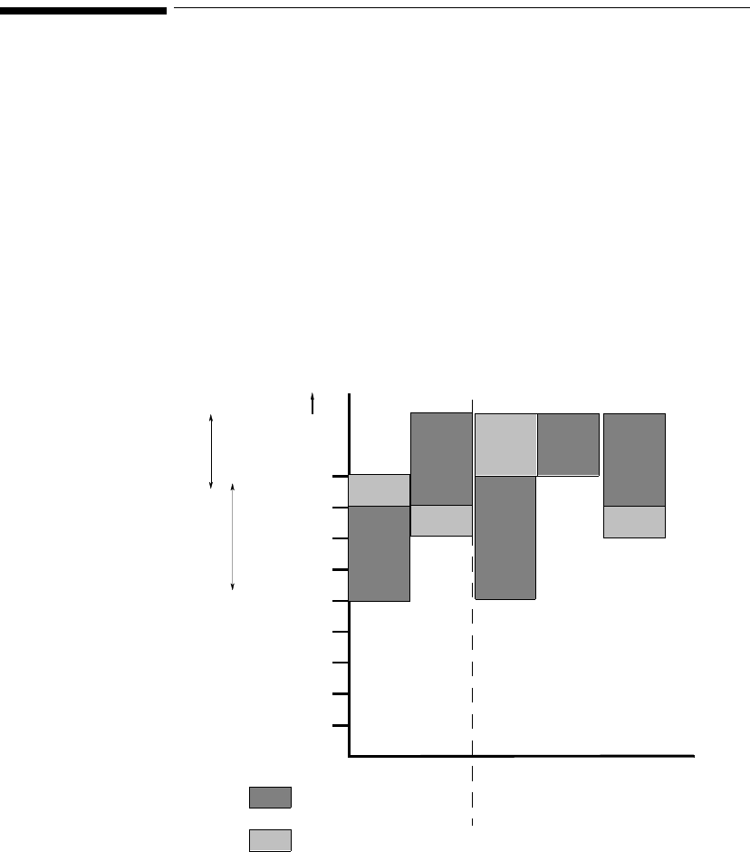
Selecting the Appropriate Transducer
4-10 SpO2 Monitoring
Selecting the Appropriate Transducer
The following chart provides a guideline to select the most appropriate
transducer for your patient.
Select the most appropriate transducer by finding the patient’s weight on the
vertical axis, and drawing a horizontal line across the chart. Each shaded area
that the line passes through represents a transducer that you can use on this
patient.
Areas of dark shading indicate that the transducer is the most appropriate one in
that weight range.
Areas of light shading indicate that you can use the transducer in this weight
range, even though it is not the most appropriate transducer.
Greater
than
50 kg
50
40
30
20
15
10
3
1
D-20 D-25 M1192A
100x140
M1191A M1194A
Preferred
Transducer
Alternative
Transducer
Disposable
Transducers Reusable Transducers
2.5
Clip
Adult
Finger
Small Adult/Pediatric
Finger
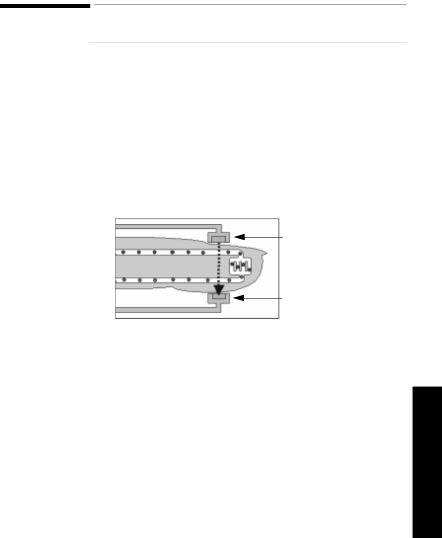
Applying the Transducer
SpO2 Monitoring 4-11
4 SpO2 Monitoring
Applying the Transducer
Overview A minimum pulsatile flow must be present at the application site of your patient
to obtain measurements.
Select an appropriate transducer and apply the transducer properly to avoid
incorrect measurements. Applying a small amount of pressure at the application
site can improve the measurement. Use one of the preferred application sites for
your transducer. Selecting the most suitable transducer and application site will
help you to ensure that:
• The light emitter and the photodetector are directly opposite each other
and that all the light from the emitter passes through the patient's tissues,
• The application site is of the correct thickness for light to pass through. If
the application site is too thick or too thin, an SpO2 NON-PULSATILE
INOP will occur. You should then select another site as appropriate.
Positioning of the Light Emitters and Photodetector
Inspect the application site every 2 to 3 hours to ensure skin integrity and correct
optical alignment. If skin integrity changes, move the transducer to another site.
Light Source
Photodetector
Applying the Transducer
4-12 SpO2 Monitoring
Warnings • Failure to apply the transducer properly may cause incorrect
measurement of SpO
2
.
• Specific attention must be given to sensor site inspection for changes
in skin quality, proper optical path alignment and attachment. Check
the application site at regular intervals and change the site if any
compromise in skin quality should occur.
• Using a transducer during MR imaging can cause severe burns. To
minimize this risk, ensure that the cable is positioned so that no
inductive loops are formed. If the transducer does not appear to be
operating properly, remove it immediately from the patient.
• Using a transducer in the presence of bright lights may result in
inaccurate measurements. In such cases, cover the site with opaque
material.
• Injected dyes, such as methylene blue, or intravascular
dyshemoglobins, such as methemoglobin, may lead to inaccurate
measurements.
• Performance may be compromised by excessive motion. This can lead
to inaccurate SpO2 readings.
• Avoid placing the SpO2 transducer on any extremity with an arterial
catheter, or intravascular venous infusion line.
• Do not use disposable transducers on patients who exhibit allergic
reactions to the adhesive.

Applying the Transducer
SpO2 Monitoring 4-13
4 SpO2 Monitoring
Adult Finger
Transducer
(M1191A)
Push the transducer over the fingertip in such a way that the fingertip touches
but does not protrude from the end of the transducer. The fingernail must be
uppermost and the cable must lie on the back of the hand. This ensures that the
light sources cover the base of the fingernail giving the best measurement
results. The cable can be held in place by the accompanying wristband.
Warning
Failure to apply the transducer properly may cause incorrect measurement
of SpO2. For example, not pushing the transducer far enough over the
finger can result in inaccurate SpO2 readings. Pushing the transducer too
far, so that the finger protrudes from the transducer, can pinch the finger,
resulting in inaccurately low SpO2 readings.
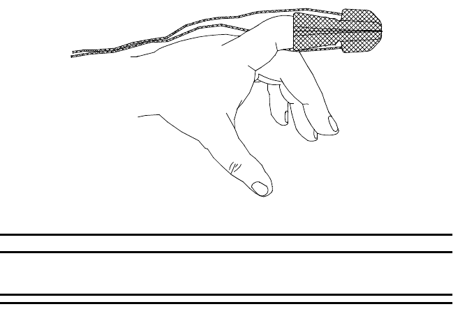
Applying the Transducer
4-14 SpO2 Monitoring
Small Adult/
Pediatric
Finger
Transducer
(M1192A)
Push the transducer over the fingertip in such a way that the fingertip touches
but does not protrude from the end of the transducer.
Warning
Failure to apply the transducer properly may reduce the accuracy of the
SpO2 measurement.

Applying the Transducer
SpO2 Monitoring 4-15
4 SpO2 Monitoring
Ear Clip
Transducer
(M1194A)
Clip the probe onto the fleshy part of the ear lobe as shown in the diagram
below. The plastic fixing mechanism helps to minimize artifact generated by
patient motion. Do not position the probe on cartilage or where it presses against
the head.
The clip transducer can be used as an alternative if the adult finger transducer
does not provide satisfactory results. The preferred application site is the ear
lobe, although other application sites with higher perfusion (such as the nostril)
can be used. Due to the physiologically lower perfusion in the ear lobe, you
should be aware of the reduced accuracy of the measurement and more frequent
INOPs.
Warning
Failure to apply the clip transducer properly may reduce the accuracy of
the SpO2 measurement.
Disposable
Transducers See the Directions for Use supplied by Nellcor® Incorporated for instructions on
preparation and application of disposable transducers.
Warning
When the specified Nellcor® transducers are used, the application must be
consistent with the manufacturer's own guidelines.

Optimizing Transducer Performance
4-16 SpO2 Monitoring
Optimizing Transducer Performance
To get the best results from your SpO2 reusable transducer:
• Always handle the transducer and cable with care. The soft finger sleeve
houses a sensitive electronic device that can be damaged by harsh
treatment. Always protect the cable from sharp-edged objects.
• Use the wristband that is supplied with your M1191A transducer. By
keeping the cable between the finger transducer and the wristband fairly
loose, you will maintain good monitoring conditions.
Normal wear and tear associated with patient movement and regular transducer
cleaning naturally mean that your transducer will have a limited lifetime.
However, provided you handle the transducer and its cable with care, you can
expect useful service from it for up to two years. Harsh treatment will drastically
reduce the lifetime of the transducer. Moreover, Agilent Technologies’ warranty
agreement shall not apply to defects arising from improper use.

Turning the SpO2 Parameter On/Off
SpO2 Monitoring 4-17
4 SpO2 Monitoring
Turning the SpO2 Parameter On/Off
Overview The SpO2 parameter is turned on or off at the Agilent Information Center by
using the Telemetry Setup Window.
Turning the SpO2 parameter off at the Information Center also turns off:
•SpO
2 alarms
•SpO
2 display of numerics
•SpO
2 trending.
After you turn SpO2 on, you should adjust the sample rate to match your
patient’s acuity by using the Wave Viewer.
After you turn SpO2 off, setting the sample rate to Manual using the Wave
Viewer will help you conserve the transmitter’s battery life.
SpO2
Parameter
Auto ON
The SpO2 parameter is automatically turned on at the Agilent Information
Center if a manual SpO2 measurement is initiated at the transmitter while in
Manual mode or the SpO2 transducer is inserted into the transmitter while the
transmitter is in continuous SpO2 mode.
When a patient is discharged and the transmitter is in Continuous mode, the
SpO2 parameter is turned off. To reactivate the SpO2 parameter Auto ON
feature from the transmitter, remember to do one of the following when a patient
is discharged:
– remove the SpO2 cable from the transmitter, wait 15 seconds, then
reinsert the cable
or
– reset the transmitter to Manual mode.
Note—
The SpO2 parameter Auto ON feature only needs to be reactivated when
the transmitter is in Continuous mode at discharge.
Note—
SpO2 can always be turned on and off at the Agilent Information Center.

Turning the SpO2 Parameter On/Off
4-18 SpO2 Monitoring
Task
Summary Turn the SpO2 parameter on or off manually by performing the following steps:
Step Action
1 On the Patient Window click the All Controls button.
2 On the All Controls Window click the Telemetry Setup button.
3 On the Telemetry Setup Window, turn SpO2 parameter on or off by
clicking in the Parameter ON checkbox. A check mark in the
checkbox indicates that SpO2 monitoring is on.

Turning SpO2 Alarms On/Off
SpO2 Monitoring 4-19
4 SpO2 Monitoring
Turning SpO2 Alarms On/Off
Overview You can turn SpO2 alarms on or off by using the Telemetry Setup Window.
Task
Summary Turn SpO2 alarm on or off by performing the following steps:
Turning the Pulse Parameter On/Off
Overview You can turn the SpO2 pulse parameter on or off by using the Telemetry Setup
Window.
Task
Summary Turn the pulse parameter on or off by performing the following steps:
Step Action
1 On the Patient Window click the All Controls button.
2 On the All Controls Window click the Telemetry Setup button.
3 On the Telemetry Setup Window turn SpO2 alarms on or off by
clicking in the Alarm ON checkbox. A check mark in the checkbox
indicates that SpO2 alarms are on.
Step Action
1 On the Patient Window click the All Controls button.
2 On the All Controls Window click the Telemetry Setup button.
3 On the Telemetry Setup turn pulse parameter on or off by clicking
in the Parameter ON checkbox. A check mark in the checkbox
indicates that pulse monitoring is on.

SpO2 Alarm and INOP Summary
4-20 SpO2 Monitoring
SpO2 Alarm and INOP Summary
SpO2 alarms are non-latching. That is, when an SpO2 limit is exceeded, if the
alarm is not silenced, it will reset automatically if the patient’s alarm condition
returns within the limits. This reduces the number of times you will need to reset
alarms at the information center when an alarm condition has been corrected at
the patient’s side (for example, movement-induced artifact alarms).
The following table lists the SpO2 alarms and the description of the conditions
required to generate these alarms.
Message Level Sound Description
**SpO2 > upper limit Yellow Continuous SpO2 value greater than the upper SpO2
measurement limit.
Important—
Setting the high SpO2 alarm limit to
100% is equivalent to switching off the high
alarm.
**SpO2 < low limit Yellow Continuous SpO2 value less than the lower SpO2
measurement limit.

SpO2 Alarm and INOP Summary
SpO2 Monitoring 4-21
4 SpO2 Monitoring
The following table lists the SpO2 INOPs. The Action column includes
recommendations on what to do when one of these INOPs occurs.
Note—
A Hard INOP indicates a more severe situation than a soft INOP. Hard
INOPS have an audible tone, and monitoring and alarms are disabled. In a soft
INOP, no audible tone is generated; monitoring and alarms remain active.
Message Type Description Action
SpO2 EQUIP MALF Hard INOP Malfunction in the SpO2
hardware, or transducer/
adapter cable damaged
Change transducer.
Change adapter cable.
If INOP persists, replace
transmitter.
SpO2 ERRATIC Hard INOP Erratic SpO2 measurements,
often due to a faulty
transducer or incorrect
positioning of the transducer
May also be caused by
optical shunting if sensor too
big or too small.
Line up light source and
photodetector - they must
be opposite each other and
light must pass through the
arteriolar bed.
Reposition transducer to
site with higher perfusion.
Replace transducer or
adapter cable.
Use different sensor with
correct fit.

SpO2 Alarm and INOP Summary
4-22 SpO2 Monitoring
SpO2
INTERFERENCE Hard INOP Level of ambient light is so
high that the SpO2 transducer
cannot measure SpO2 or
pulse rate.
Transducer or adapter cable
is damaged.
May also be due to electrical
interference.
May also be generated by a
defective transmitter.
Cover sensor with non-
white opaque material (for
example, pulse oximeter
probe wraps - Posey wrap
or equivalent) to reduce
ambient light.
If INOP persists, inspect
and replace transducer or
adapter cable as needed.
Reduce sources of
electrical interference.
If the above corrective
actions are ineffective, use
a different transmitter, and
call service to replace the
defective one.
SpO2 NO
TRANSDUCER Hard INOP SpO2 transducer is
disconnected.
SpO2 connector on
transducer or transmitter is
dirty.
Reconnect sensor.
Replace sensor.
Replace transmitter and
call service.
SpO2 NOISY
SIGNAL Hard INOP Excessive patient movement
or electrical or optical
interference is causing
irregular pulse patterns
Locate sensor at site with
less movement.
Reduce sources of
electrical or optical
interference.
Call service.
Message Type Description Action

SpO2 Alarm and INOP Summary
SpO2 Monitoring 4-23
4 SpO2 Monitoring
SpO2 NON-
PULSATILE Hard INOP Pulse too weak or not
detectable
May also be generated by a
defective transmitter.
Relocate sensor to site with
improved circulation.
Warm area to improve
circulation.
Try another sensor type.
If the above corrective
actions are ineffective, use
a different transmitter, and
call service to replace the
defective one.
SpO2 TRANS
MALFUNC Hard INOP The SpO2 transducer is
malfunctioning.
SpO2 connector on the
transducer or transmitter is
dirty or corroded.
Replace the transducer or
adapter cable.
Change the transmitter and
call service to repair.
Message Type Description Action
SpO2 Alarm and INOP Summary
4-24 SpO2 Monitoring

Agilent Wave Viewer Basics 5-1
5 Wave Viewer Basics
5
Agilent Wave Viewer Basics
This chapter provides information about the Agilent Wave Viewer, which
consists of the supplied Agilent Wave Viewer, Hewlett-Packard Palmtop
Computer, and a light pipe. It includes the following sections:
• Indications for Use . . . . . . . . . . . . . . . . . . . . . . . . . . . . . . . . . . . . . . . . 5-2
• Introducing the Wave Viewer . . . . . . . . . . . . . . . . . . . . . . . . . . . . . . . .5-5
• Installing the Wave Viewer. . . . . . . . . . . . . . . . . . . . . . . . . . . . . . . . . .5-7
• Connecting to the Transmitter. . . . . . . . . . . . . . . . . . . . . . . . . . . . . . . .5-9
• Introducing the Wave Viewer . . . . . . . . . . . . . . . . . . . . . . . . . . . . . . . .5-5
• Software License Agreement . . . . . . . . . . . . . . . . . . . . . . . . . . . . . . .5-17
Note—
For information about other aspects of Wave Viewer, please refer to the
following documentation:
Cleaning of palmtop Chapter 7
Configuration Chapter 8
Using palmtop for non-Wave
Viewer applications HP Palmtop User’s Guide
(F1060-90001)

Indications for Use
5-2 Agilent Wave Viewer Basics
Indications for Use
The paragraphs below are the elements of the indications for use statement for
the Agilent Wave Viewer.
Condition Agilent Wave Viewer is generally indicated when the clinician decides to assess
the ECG or SpO2 vital signs of adult and pediatric patients while at the patient
location and does not need a diagnostic quality display.
Prescription
Versus Over-
the-Counter
Agilent Wave Viewer is a prescription device.
Part of the
Body or Type
of Tissue with
Which the
Device
Interacts
Agilent Wave Viewer does not contact the body or tissue of the patient.
Frequency of
Use Agilent Wave Viewer is indicated for use when prescribed by a clinician.
Physiological
Purpose Agilent Wave Viewer is indicated when the physiological purpose is to gain
information for treatment, to assess adequacy of treatment, or to rule out causes
of symptoms. Agilent Wave Viewer is not suitable for continuous patient
monitoring or detailed diagnostics.
Patient
Population Adult and pediatric ambulatory and non-ambulatory patients.

Indications for Use
Agilent Wave Viewer Basics 5-3
5 Wave Viewer Basics
Intended Use Agilent Wave Viewer is intended to be used as a patient assessment tool as an
adjunct to the monitoring provided at the central station, not as a substitute. Uses
are limited to gross assessment of a patient’s condition and intermittent reading
of ECG/pleth waveforms and pulse/SpO2 values. Indicated categories of use
include but are not limited to:
• Determination of a patient’s tolerance to exercise during ambulation.
• Patient assessment while waiting for information from the central station
or for monitoring, diagnostic or therapeutic equipment to arrive.
• Additional input to a routine physical assessment of a patient such as
reading and recording SpO2 values while on rounds.
• Gross assessment of a patient that can be clearly determined by visual
interpretation of physiological waveforms of monitoring bandwidth by a
trained clinician, such as asystole and ventricular fibrillation.
• Other standard uses of portable SpO2 monitors, such as assessment of
ventilation and/or O2 therapy.
Agilent Wave Viewer uses specifically excluded are:
• Continuous monitoring of a patient. (Agilent Wave Viewer is not intended
as a bedside monitor since alarms and ECG algorithms are not provided.)
• Determining detailed ECG diagnosis such as ST segment values, R-R
variability, or other diagnostic ECG values. (Signals are of monitoring
quality only, NOT diagnostic quality. Automated algorithms such as
arrhythmia and a cardiotach are not provided.)
• Monitoring a patient during therapeutic procedures such as defibrillation
or electrosurgery.
• Agilent Wave Viewer should never be used outside the coverage area
provided by the antenna system and central station.

Indications for Use
5-4 Agilent Wave Viewer Basics
Warning Agilent Wave Viewer is not intended for the following purposes:
– A diagnostic patient monitoring tool. The Agilent Wave Viewer
should not be used for detailed ECG diagnosis, such as ST
segment values, R-R variability, or any other diagnostic ECG
values.
– A bedside monitor. Continuous monitoring (10 minutes or more)
of a patient is not supported.
– Monitoring a patient during therapeutic procedures, such as
defibrillation or electrosurgery.
No patient alarms are articulated at the Agilent Wave Viewer. Telemetry
alarms are presented at the central monitor only, and all alarm adjustments
must be made at central.
Do not use the Agilent Wave Viewer outside the coverage area provided by
the antenna system and the central station.
Do not use the AC power adapter for the Hewlett-Packard 200LX Palmtop
Computer in the patient care vicinity. The AC power adapter meets
standard electrical safety requirements, but not the stricter requirements
for medical equipment used near patients.

Introducing the Wave Viewer
Agilent Wave Viewer Basics 5-5
5 Wave Viewer Basics
Introducing the Wave Viewer
The Wave Viewer is a patient assessment tool that allows you to determine the
basic cardio-pulmonary condition of a patient while at the patient’s side. Wave
Viewer enables “snapshot” views of a patient’s condition, thus contributing to
nursing productivity. Wave Viewer is designed for uses such as:
– Verification of correct placement of ECG electrodes and the SpO2
sensor.
– Patient assessment while waiting for other monitoring, diagnostic or
therapeutic equipment to arrive.
– Gathering additional input during a routine physical assessment of
an ambulatory or non-ambulatory patient.
Wave Viewer provides the following functionality:
• Displays the realtime ECG and pleth waveforms, as well as SpO2 and
pulse values.
• Enables choice of SpO2 measurement times - continuous, 1 or 5 minute
intervals, or manual (on demand). In intermittent and manual modes,
STAT measurements can be made at any time.
• Displays ECG and SpO2 measurement INOPs at the point of care.
• Allows configuration of parameters, transmitter, and transmitter
frequencies (under password control).
• Enables configuration of replacement transmitters and transfer of settings
from one transmitter to another (under password control).
• Consists of the supplied Agilent Wave Viewer, Hewlett-Packard palmtop
computer, stick-on label, and light pipe.
Use of the Wave Viewer as a patient assessment tool is intended as an adjunct to
the monitoring provided at the Agilent Information Center, not as a substitute.
The Wave Viewer is not intended for continuous monitoring.
The Wave Viewer cannot be used for making adjustments to SpO2 or ECG (if
lead select is enabled) outside the coverage area provided by the antenna system
and the information center.
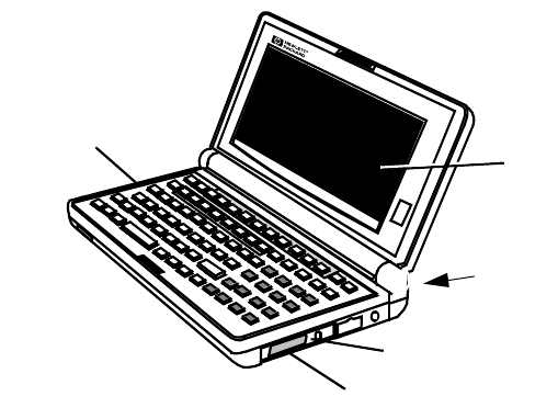
Introducing the Wave Viewer
5-6 Agilent Wave Viewer Basics
.
Environmental
Limits To maintain product reliability, avoid getting the equipment wet and observe the
temperature and humidity limits for the palmtop as listed in “Environmental
Conditions” on page 9-21. If the environmental limits are exceeded,
performance may no longer meet specifications.
FLASH CARD INSERTION
DISPLAY
BATTERY
COMPARTMENT
(Underneath)
INFRARED
PORT
BACKUP
BATTERY
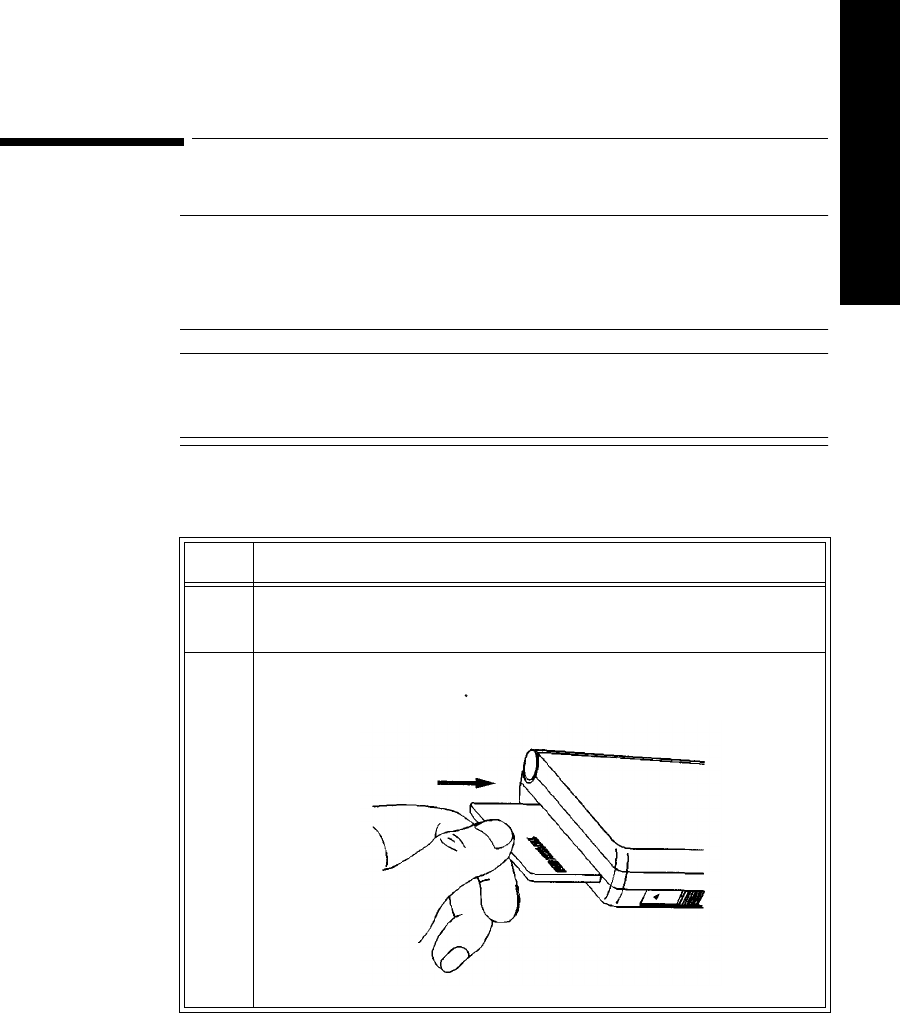
Installing the Wave Viewer
Agilent Wave Viewer Basics 5-7
5 Wave Viewer Basics
Installing the Wave Viewer
Overview Before installing the Wave Viewer, the palmtop must be operational. if the
palmtop is not operational, see the palmtop user documentation for start-up
instructions.
Caution
Agilent Technologies does not guarantee correct operation of the Wave Viewer
when other applications are active on the palmtop computer. Rebooting while
files or other applications are open can cause file or directory corruption.
Task
Summary Install the Wave Viewer by performing the following steps:
Step Action
1 Turn the palmtop on. If any applications are open, close them until
your personal information screen appears. Turn the palmtop off.
2 Insert the Agilent Wave Viewer flash disk card - red arrow side up -
into the left end of the palmtop. Turn the palmtop on.

Installing the Wave Viewer
5-8 Agilent Wave Viewer Basics
3Press the ++ keys simultaneously to reset (reboot)
the system. The “Welcome to the Agilent Wave Viewer” screen
displays, followed by the “Communication Disrupted” screen.
Note—
If the Agilent Wave Viewer does not start up when you insert
the disk card, the palmtop may be out of batteries, or the palmtop
may have insufficient memory. Two (2) megabytes of memory are
required to run the Agilent Wave Viewer.
4 To access patient measurements, continue by connecting the
palmtop to the transmitter.
Step Action
CTRL
ALT DEL
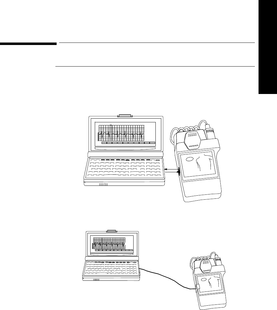
Connecting to the Transmitter
Agilent Wave Viewer Basics 5-9
5 Wave Viewer Basics
Connecting to the Transmitter
Overview The Wave Viewer connects to the transmitter through the infrared port on the
palmtop. The connection can be made in either of two ways.
• Directly, by alignment only.The palmtop is positioned within the infrared
cone of the transmitter. No additional equipment is needed.
• Through a physical connection using a fiber-optic light pipe. When
connected, the transmitter can be moved freely within the light-pipe range.
Estimate
HR
System
Setup
System
Info
SpO2
Quality
SpO2
Numbers
ECG
Screen
Help
Menu
72
96
pulse
SpO2
Lead II
1mV
F1 F2 F3 F4 F5 F6 F7 F8 F9 F10
Estimate
HR
System
Setup
System
Info
SpO2
Quality
SpO2
Numbers
ECG
Screen
Help
Menu
72
96
pulse
SpO2
Lead II
1mV
F1 F2 F3 F4 F5 F6 F7 F8 F9 F10
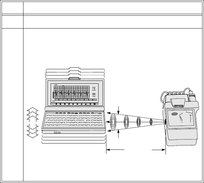
Connecting to the Transmitter
5-10 Agilent Wave Viewer Basics
Connecting
Directly To connect the palmtop to the Agilent Transmitter directly, perform the
following steps:
Step Action
1 Turn the palmtop on.
2 Align the infrared port on the palmtop with the infrared port on the
transmitter. Make sure that the palmtop port is positioned inside the
infrared cone generated at the transmitter. A distance between 1 and
6 inches gives optimum results.
The Main Screen displays.
Estimate
HR
System
Setup
System
Info
SpO2
Quality
SpO2
Numbers
ECG
Screen
Help
Menu 15 deg.
maximum
14 cm (6 in)
maximum
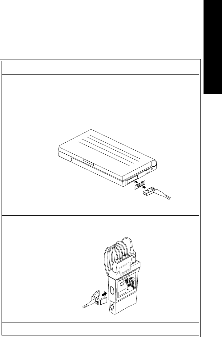
Connecting to the Transmitter
Agilent Wave Viewer Basics 5-11
5 Wave Viewer Basics
Connecting
with a Light
Pipe
To connect the palmtop to the Agilent Transmitter with a fiber optic light pipe,
perform the following steps:
Step Action
1
Note—
In order to be used with a light pipe, the palmtop must have a
special cover over the infrared port. This cover is packaged with the
light pipe. If the palmtop is missing the cover, contact service for
assistance.
Connect the small end of the light pipe to the protrusion on the
cover over the infrared port of the palmtop.
2 Attach the clip end of the light pipe to the transmitter, covering the
infrared port completely.
3 Turn the palmtop on. The Main Screen displays.

Connecting to the Transmitter
5-12 Agilent Wave Viewer Basics
Caution
The light pipe is made of optical-grade plastic and is therefore subject to
breakage. Always handle the light pipe with care. Do not coil the light pipe
smaller than 10 cm (4 in) in diameter. Do not kink or bend the pipe sharply, or
otherwise handle it roughly.

Battery Information
Agilent Wave Viewer Basics 5-13
5 Wave Viewer Basics
Battery Information
Battery
Types and
Battery Life
Main Battery Type. Any brand of 1.5-volt, size AA Alkaline batteries or
Nickel-Cadmium or Nickel-Metal Hydride (NiMH) rechargeable batteries.
Backup Battery Type. 3-volt CR2032 lithium coin cell. If fresh main batteries
are maintained, the backup battery should last a year before you replace it.
The battery life you get with your palmtop depends on:
• The type and quality of batteries you use.
• How you use your palmtop. (Things like IR and serial communications,
modems, and flash-disk memory cards all require higher current and
therefore drain your batteries faster.)
• Whether you use the AC adapter.
For typical use without the AC adapter, fresh Alkaline batteries should last from
2 to 8 weeks. Rechargeable batteries used without the AC adapter will get less
life than Alkalines--how much less depends on the quality and type of the
rechargeable batteries you use.
The best way to extend battery life is to use the AC adapter whenever possible.
Warning
Do not use the palmtop AC power adapter in the patient care vicinity. The
AC power adapter meets standard electrical safety requirements, but not
the stricter requirements for medical equipment used near patients.
When you see the message telling you that the main batteries are low, replace
them as soon as possible. This will help you get the most out of your backup
battery.
Battery Information
5-14 Agilent Wave Viewer Basics
Battery
Status The Agilent Wave Viewer software monitors the palmtop battery voltage and
informs you of the need to replace the batteries via a screen message.
You can also use the battery monitor in the “setup” program within the palmtop
System Manager to predict the remaining battery capacity. When the indicator
falls below the 1/4 level, fresh alkaline batteries should be installed.
Additionally, the palmtop has a self test ( ) that includes reading the
battery voltage. This self test procedure necessitates rebooting of the palmtop.
When to
Replace
Palmtop
Batteries
When you see a low-battery message in the display, replace the indicated
batteries as soon as possible. If the palmtop beeps and turns off immediately
after you turn it on, replace the main batteries.
The backup battery, which prevents data loss when the main batteries are dead
or out of the unit, should be changed a year after it is installed even if a low
backup-battery message doesn’t appear.
Removing
and
Installing
Palmtop
Batteries
Caution
Do not remove the main batteries if the backup battery is dead--complete
memory loss will result. Replace the backup battery first in this case.
Warning
Do not mutilate, puncture, or dispose of batteries in fire. The batteries can
burst or explode, releasing hazardous chemicals. Replace batteries with
only the types recommended in this manual. Discard used batteries
according to the manufacturer’s instructions. The back-up (lithium) battery
can explode if it is inserted incorrectly.
ESC ON
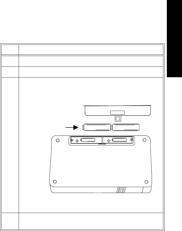
Battery Information
Agilent Wave Viewer Basics 5-15
5 Wave Viewer Basics
Changing the
Main Batteries Change the main batteries by performing the following steps.
Step Action
1 Close all open applications before changing batteries.
2Important: Turn your palmtop off and close the case.
3 Remove the battery cover and old batteries.
4 Install two fresh AA batteries, orienting them as shown by the
symbols in the battery compartment.
Main Batteries

Battery Information
5-16 Agilent Wave Viewer Basics
Changing
the Backup
Battery
Caution
Do not remove both the main batteries and the backup battery at the same time--
complete memory loss will result.
Change the backup battery by performing the following steps.
5Replace the cover and turn your palmtop on. If the palmtop won’t
turn on after you replace the batteries, go back over the procedure
and check the orientation of the batteries as shown in Step 3--you
may have put the batteries in backwards.
6 If you replaced rechargeable batteries (either with Alkalines or
another set of rechargeables) be sure to go into Setup and set or
verify your battery type and charging setting. (Battery charging is
automatically disabled whenever you remove rechargeable
batteries.) See the palmtop User’s Guide for more information.
Step Action
Step Action
1Important: Turn the palmtop off.
2 Remove the backup-battery cover and pull out the battery tray.

Software License Agreement
Agilent Wave Viewer Basics 5-17
5 Wave Viewer Basics
Software License Agreement
ATTENTION: USE OF THE SOFTWARE IS SUBJECT TO THE
AGILENT TECHNOLOGIES SOFTWARE LICENSE TERMS SET
FORTH BELOW. USING THE SOFTWARE INDICATES YOUR
ACCEPTANCE OF THESE TERMS. IF YOU DO NOT ACCEPT THESE
TERMS, YOU MAY RETURN THE SOFTWARE FOR A FULL
REFUND. IF THE SOFTWARE IS SUPPLED WITH ANOTHER
PRODUCT, YOU MAY RETURN THE ENTIRE UNUSED PRODUCT
FOR A FULL REFUND.
Agilent
Technologies
Software
License
Terms
The following terms govern your use of the enclosed software programs
(Software) unless you have a separate written agreement with Agilent
Technologies.
License Grant. Agilent Technologies grants you a license to Use one copy of the
version of the Software identified in your documentation on any one product.
“Use” means storing, loading, installing, executing or displaying the Software. If
the Software is authorized for concurrent use, only that number of users allowed
under your network license limits controls or otherwise authorized by Agilent
Technologies may Use the Software concurrently.
3 Remove the old battery from the tray and insert a fresh, 3-volt
CR2032 coin cell. Be sure the “+” on the battery is facing down in
the tray.
4 Insert the battery tray back into the palmtop and replace the cover.
5 Turn the palmtop on. If the battery-low message is still present in
the display, go back over the procedure and check the battery
orientation as shown in Step 3--you may have put the battery in the
tray upside down.
Step Action
Software License Agreement
5-18 Agilent Wave Viewer Basics
Ownership. The Software is owned and copyrighted by Agilent Technologies or
its third party licensors. Your license confers no title of ownership in the
Software and should not be construed as a sale of any rights in the Software.
Agilent Technologies’ third party licensors may protect their rights in the event
of any violation of these terms.
Copies and Adaptations: You may only make copies or adaptations of the
Software for archival purposes or when copying or adaptation is an essential
step in the authorized Use of the Software. You must reproduce all copyright
notices in the original Software on all authorized copies or adaptations. You may
not copy the Software onto any bulletin board or a similar system.
No Disassembly or Decryption. You may not disassemble, decompile or decrypt
the Software unless Agilent Technologies’ prior written consent is obtained. In
some jurisdictions, Agilent Technologies’ consent may not be required for
disassembly or decompilation. Upon request, you will provide Agilent
Technologies with reasonably detailed information regarding any disassembly or
decompilation.
Transfer. Your license will automatically terminate upon any transfer of the
Software. Upon transfer, you must deliver all copies of the Software and related
documentation to the transferee. The transferee must accept these License Terms
as a condition to the transfer.
Termination. Agilent Technologies may terminate your license upon notice for
failure to comply with any of these License Terms. Upon termination, you must
immediately destroy the Software, together with all copies, adaptations and
merged portions in any form.
Export Requirements. You may not export or re-export the Software or any copy
or adaptation in violation of any applicable laws or regulations.
U.S. Government Restricted Rights. The Software and documentation are
provided with Restricted Rights. Use, duplication, or disclosure by the U.S.
Government is subject to the restrictions set forth in subparagraph (c)(1)(ii) of
the Rights in Technical Data and Computer Software clause in DFARS 252.227-
7013 or as set forth in subparagraph (c)(1)and (2) of the Commercial Computer
Software-Restricted Rights clauses at 48 CFR 52.227-19, as applicable. The
Contractor for the Software is Agilent Technologies, 3000 Hanover Street, Palo
Alto, California 94304.

Wave Viewer Operation 6-1
6 Wave Viewer Operation
6
Wave Viewer Operation
This chapter provides directions for operating the Agilent Wave Viewer. It
includes the following sections:
• Wave Viewer Controls . . . . . . . . . . . . . . . . . . . . . . . . . . . . . . . . . . . . .6-2
• Using the Wave Viewer . . . . . . . . . . . . . . . . . . . . . . . . . . . . . . . . . . . .6-3
• Troubleshooting . . . . . . . . . . . . . . . . . . . . . . . . . . . . . . . . . . . . . . . . .6-14
• Wave Viewer Inoperative Messages (INOPs) . . . . . . . . . . . . . . . . . . 6-15
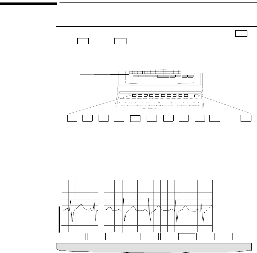
Wave Viewer Controls
6-2 Wave Viewer Operation
Wave Viewer Controls
Keys Wave Viewer can be operated with only 11 keys - the 10 function keys
through - and the key. Functions are defined by the corresponding
label on the screen.
.
Main Screen The Main Screen displays the realtime ECG waveform and the SpO2 status.
Labels at the bottom of the display provide access to other screens where you
can view data and change settings.
Main Screen with ECG and Continuous SpO2
F1
F10
ON
Labels Estimate
HR
Syst em
Setup
System
Info
SpO2
Quality
SpO2
Numbers
ECG
Screen
Help
Menu
96
SpO2
1mV
ON
ON
F1 F2 F3 F4 F5 F6 F7 F8 F9 F10
F1 F2 F3 F4 F5 F6 F7 F8 F9 F10
F1 F2 F3 F4 F5 F6 F7 F8 F9 F10
Function Keys
72
96
PULSE
F1 F2 F3 F4 F5 F6 F7 F8 F9 F10
% SpO2
1mV Help ECG SpO2/
Pleth Setup
SpO2Config Est
HR

Using the Wave Viewer
Wave Viewer Operation 6-3
6 Wave Viewer Operation
Using the Wave Viewer
Overview This section describes actions you can complete using the Wave Viewer. The
directions in this section assume the palmtop PC is dedicated to Wave Viewer
use. If the palmtop is used for other applications, use the instructions for
Installing the Wave Viewer and Exiting from the Wave Viewer.
Action See page...
Check the ECG signal quality 6-4
View other standard ECG leads 6-5
View EASI leads 6-6
Change the lead (standard ECG only) 6-7
Adjust the ECG size 6-7
Estimate Heart Rate 6-8
Check the SpO2 signal quality 6-9
Change the SpO2 sample rate 6-10
Make STAT SpO2 measurements 6-11
Use the Help Menu 6-12
Deactivate the Wave Viewer 6-13
Power Save Mode 6-13
Exit the Wave Viewer 6-13

Using the Wave Viewer
6-4 Wave Viewer Operation
Checking
ECG Signal
Quality
You can use the Wave Viewer to check the quality of the ECG signal to ensure
accurate monitoring.
Task Summary Check the ECG signal quality by performing the following steps:
Step Action
1 Connect the ECG lead set from the patient to the transmitter.
2 Open the palmtop and press . The Communication Disrupted
screen displays.
3 Align the transmitter and the palmtop. The Main Screen displays.
See directions under “Connecting Directly” on page 5-10 or
“Connecting with a Light Pipe” on page 5-11.
4 Check the ECG quality. See the Agilent Information Center User’s
Guide for the characteristics of an optimal ECG signal for paced and
non-paced patients.
On

Using the Wave Viewer
Wave Viewer Operation 6-5
6 Wave Viewer Operation
Viewing
Other
Standard
ECG Leads
You can use the Wave Viewer to view other leads at the patient’s side. Changes
made to lead selection at the Wave Viewer are not sent to the Agilent
Information Center unless you are using a 3-lead cable with Lead Select on. The
system must be configured for this capability. See “Changing the Lead
(Standard ECG only)” on page 6-7.
Task Summary View other standard ECG leads with the Wave Viewer by performing the
following steps:
Step Action
1 From the Wave Viewer Main Screen, press ECG.
2 Select the lead by performing one of the following:
For 5-wire
Press Select Lead, then select the lead. Lead selection affects only
the Wave Viewer display; selection made at the Wave Viewer is not
reflected at Agilent Information Center.
For 3-wire (Lead Select off)
To monitor a different lead:
1. View the lead placement diagram by pressing the appropriate
lead key.
2. Follow the electrode placement diagram on the Wave Viewer to
reposition the electrodes appropriately.
3. Assign the correct lead label at the Agilent Information Center.
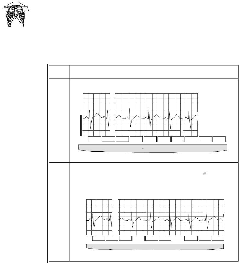
Using the Wave Viewer
6-6 Wave Viewer Operation
Viewing
EASI Leads You can use the Wave Viewer to view the directly acquired or “raw” EASI leads
(AI, AS, ES) at the patient’s side. The reconstructed leads (I, II, III, aVR, aVL,
aVF, V1, V2, V3, V4, V5, and V6) are not available at the Wave Viewer.
Changes made to lead selection at the Wave Viewer are not sent to the Agilent
Information Center.
Task Summary View the directly acquired EASI leads with the Wave Viewer by performing the
following steps:
1
2
3
4
5
EASI
Step Action
1 From the Wave Viewer Main Screen, press EASI.
2 Select the lead. Lead selection affects only the Wave Viewer
display; selection made at the Wave Viewer is not reflected at
Agilent Information Center.
.
72
96
PULSE
F1 F2 F3 F4 F5 F6 F7 F8 F9 F10
% SpO
2
1mV Help EASI SpO2/
Pleth Setup
SpO2 Config Est
HR
EASI AS
SpO2
Estimate
1mV
RightEnd
F1 F2 F3 F4 F5 F6 F7 F8 F9 F10
EASI AS
Help AI AS ES
Inc
Size Size
Dec
Est
HR Main
Screen

Using the Wave Viewer
Wave Viewer Operation 6-7
6 Wave Viewer Operation
Changing
the Lead
(Standard
ECG only)
If you have a 3-wire lead set with Lead Select on (the system must be configured
for this capability), you can use the Wave Viewer to change the lead that is
transmitted to the Agilent Information Center. Lead selection at the Agilent
Information Center is disabled.
Task Summary To change the lead, perform the following steps:
Adjusting
ECG Size You can use the Wave Viewer to adjust the ECG size. Size adjustments affect
only the ECG at the Wave Viewer. Changes made to the ECG display size at the
Wave Viewer are not sent to the Agilent Information Center.
Note—
The size setting is stored in the transmitter. If you connect the same
transmitter to a different Wave Viewer, the size last displayed will be shown.
Task Summary Adjust the ECG size on the Wave Viewer by performing the following steps:
Step Action
1 From the Wave Viewer Main Screen, press ECG.
2 Select the lead.
Lead selection made at the Wave Viewer is reflected at the Agilent
Information Center.
Step Action
1 From the Wave Viewer Main Screen, press ECG (for standard
ECG) or EASI (for EASI transmitters).
2 Adjust the size using Incr Size and Decr Size.
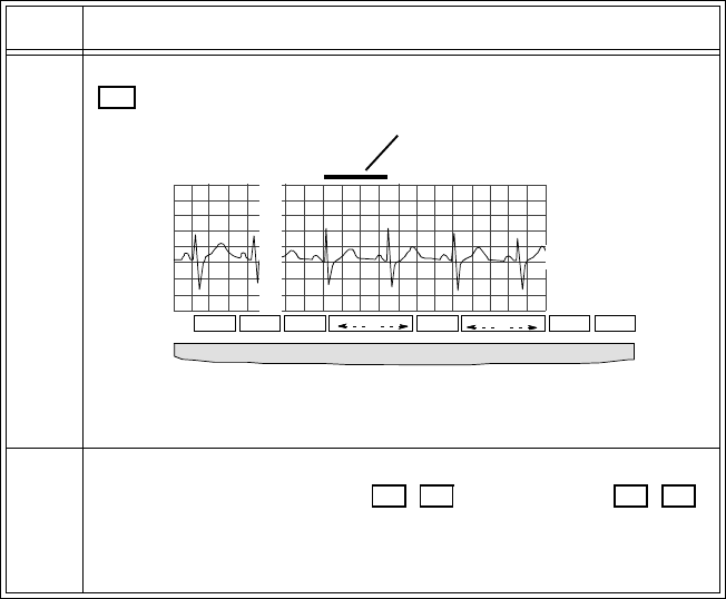
Using the Wave Viewer
6-8 Wave Viewer Operation
Estimating
the Heart
Rate
You can use the Wave Viewer to estimate heart rate.
Note—
The estimated heart rate should only be used for gross assessment of the
patient. The estimated heart rate is calculated from only two beats (versus an
average over time, as is done with most cardiotachs). Thus it can be impacted by
variations in the R-R interval and caliper positioning.
Task Summary Estimate the heart rate by performing the following steps:
Step Action
1 From either the Main Screen or the ECG Screen, press Est HR or
.
2 Position the horizontal caliper bar (above the waveform) over the R-
R interval using the Left End (, ) and Right End ( , )
keys.
The estimated Heart Rate displays at the right.
F9
SpO2
Estimate
102
1mV RightEnd
F1 F2 F3 F4 F5 F6 F7 F8 F9 F10
Lead II
Help ECG Left End Right End Main
Screen
Estimated
HR
Adjust the bar
to span an/R-R
interval/to
obtain HR.
Caliper bar
F4 F5 F7 F8

Using the Wave Viewer
Wave Viewer Operation 6-9
6 Wave Viewer Operation
Checking
SpO2 Signal
Quality
You can use the Wave Viewer to check the SpO2 signal quality.
Task Summary Check the SpO2 signal quality by performing the following steps:
Step Action
1 From the Main Screen, press SpO2 /Pleth or . Check that the
pleth wave rises and falls in synchronization with the R-peaks on the
ECG wave. This indicates that every pulse is being captured by the
SpO2 sensor.
2 From either the Main Screen or the ECG Screen, press Est HR or
to check that the pulse rate does not deviate far from the heart
rate estimated from the ECG wave. See “Estimating the Heart Rate”
on page 6-8.
The measurement is reliable if the estimated heart rate approximates
the pulse rate.
3 If the measurement is not reliable, that is if the rise and fall of the
pleth wave does not match the rise and fall of the ECG wave, or if
the pulse rate is not close to the heart rate, there may be motion
artifact or inadequate pulsatile flow. To correct:
• Warm the site to increase perfusion, or change to another site
with stronger pulsations.
• Change the site to one with less motion (usually the ear).
• Check that the sensor is positioned correctly. (See “Applying
the Transducer” on page 4-11.)
F3
F9

Using the Wave Viewer
6-10 Wave Viewer Operation
Changing
the SpO2
Sample Rate
You can use the Wave Viewer to change the rate at which the SpO2 is measured,
known as the “sample rate”. SpO2 can be measured automatically or manually.
The automatic choices are:
• Continuous (Always On)
• Intermittent at 1-minute intervals
• Intermittent at 5-minute intervals
Automatically-generated measurements begin as soon as they are set. If an
intermittent interval is chosen, you can also make a STAT measurement without
resetting the interval timing. This means, for example, that you don’t have to
wait for the next measurement with 5-minute intervals.
In Manual mode, the SpO2 parameter is not measured except when you initiate a
STAT measurement. A STAT measurement is a continuous measurement for
one minute.
Intermittent and STAT measurements are displayed at the Agilent Information
Center along with the time the measurement was received. They remain on the
display for up to 1 hour. In the Trend Review window, intermittent and STAT
measurements appear as a non-continuous trend line.
Important—
When SpO2 is not in use, setting the sample rate to Manual will
conserve transmitter battery power.
Task Summary Change the SpO2 sample rate by performing the following steps:
Step Action
1 From the Main Screen, press Setup SpO2 or .
2 Select the sample rate:
• Always On (continuous)
• Intermittent - 5-minute intervals
• Intermittent - 1-minute intervals
•Manual
F5
Using the Wave Viewer
Wave Viewer Operation 6-11
6 Wave Viewer Operation
Making a
STAT SpO2
If SpO2 is not being measured continuously (sample rate = 1 minute, 5 minute,
or Manual), you can use the Wave Viewer to make a STAT measurement at any
time.
Note—
You can also initiate manual measurements directly from the transmitter.
See “Making SpO2 Measurements” on page 4-6 for details.
Task Summary To make a STAT SpO2 measurement, perform the following steps:
Step Action
1 From the Main Screen, press .
The SpO2 and pulse rate, along with the pleth waveform, display on
the SpO2/Pleth screen for one minute.
2 Verify the quality of the SpO2 signal. See “Checking SpO2 Signal
Quality” on page 6-9.
3 When done, press End STAT or , or wait one minute until the
measurement period is ended. The Main Screen displays
automatically.
4 When the red light in the sensor goes out, remove the transducer
from the patient.
Note—
Ending a STAT measurement by removing the SpO2 sensor
from the patient before the sensor light has turned off and/or without
pressing End STAT will create an INOP (either SpO2 Nonpulsatile
or SpO2 No Transducer) at the Agilent Information Center.
F3
F10
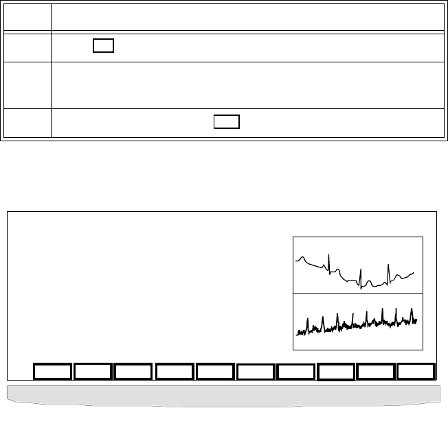
Using the Wave Viewer
6-12 Wave Viewer Operation
Using Help The Help screens provide information that supports you in learning to use the
Wave Viewer and to assist you in obtaining accurate information.
Task Summary Access the Help Menu by performing the following steps:
Sample Help Frame
Step Action
1Press from any screen. The Help Menu displays.
2 From the Help Menu, you can choose additional information on any
aspect of the Wave Viewer you need.
3 Exit from Help by pressing .
F1
F10
ECG Wave
Avoid these problems:
1. Baseline Wander
2. Muscle Artifacts
If your wave looks like this, prep skin and
change electrodes.
1
2
F1 F2 F3 F4 F5 F6 F7 F8 F9 F10
SetUp
ECG ECG
Wave Setup
SpO2 SpO2
Quality To
Cnect To
Exit To
Restart Exit
Help
Using the Wave Viewer
Wave Viewer Operation 6-13
6 Wave Viewer Operation
Deactivating
the Wave
Viewer
Agilent Technologies recommends that you deactivate the Wave Viewer by
turning the palmtop off between use in order to preserve battery life.
Task Summary Turn the palmtop off by performing the following steps:
Power Save
Mode If there is no keypress at the Wave Viewer for 10 minutes, the palmtop
automatically shuts off.
Task Summary Resume operation after automatic shutoff by performing the following steps:
Exiting the
Wave
Viewer
To use other applications on the palmtop, you must exit from the Wave Viewer
program.
Step Action
1 Move the transmitter away from the palmtop or detach the light
pipe.
2 Turn the palmtop off by pressing the key.
On
Step Action
1Press .
2 Realign the palmtop with the same transmitter (see “Connecting to
the Transmitter” on page 5-9). The last screen displays.
OR
Align the palmtop with a different transmitter. The Main Screen
displays.
On
Troubleshooting
6-14 Wave Viewer Operation
Task Summary Exit the Wave Viewer program by performing the following steps.
Troubleshooting
If the palmtop fails to respond to keystrokes or otherwise behaves unusually,
you can do a system reset (also called reboot) to resume normal operation. To
reset, press + + simultaneously.
If a system reset is unsuccessful, you can try a hard reset by pressing
+ + (the gold arrow). When the question “Initialize RAM
Disk? Enter Y or N:” comes up, enter “N”, followed by .
If neither action resolves your problem and your batteries are fresh, contact
Service.
Step Action
1 Move the transmitter away from the palmtop or remove the light
pipe to break the infrared link.
2 At the palmtop, press to exit to DOS.
3Type 200 and press to start the Hewlett-Packard palmtop
Application Manager. You can now use the palmtop to launch other
software applications.
F10
ENTER
CTRL
ALT
DEL
CTRL ON
ENTER

Wave Viewer Inoperative Messages (INOPs)
Wave Viewer Operation 6-15
6 Wave Viewer Operation
Wave Viewer Inoperative Messages (INOPs)
The Wave Viewer presents inoperative messages (INOPs) for ECG and SpO2 at
the Wave Viewer in three different screen positions:
• ECG INOPs - above the waveform, top left
•SpO
2 INOPs - at right side of Main Screen
• Battery INOPs - full screen display
Wave Viewer INOPs (in alphabetical order)
Message Description Action
ECG Equipment
Malfunction ECG circuit in transmitter is
malfunctioning.
An EASI transmitter is being
used with a pre-release C
Wave Viewer.
An EASI transmitter:
• does not have a 5-wire
leadset attached
• does not have the 5-wire
leadset inserted all the
way
• has no leadset attached
• has a 3-wire leadset
attached.
Replace transmitter.
Contact service.
Attach a 5-wire leadset.
LEADS OFF -
Check Transmitter Lead(s) not connected. Reconnect lead(s). Use transmitter lights or
Wave Viewer to confirm.
RF Out of Lock Used by service for
troubleshooting the radio
signal.
Contact service.

Wave Viewer Inoperative Messages (INOPs)
6-16 Wave Viewer Operation
SpO2 Equip
Malfunction Malfunction in the SpO2
hardware, or transducer/
adapter cable damaged.
Change sensor.
Change adapter cable.
If INOP persists, replace transmitter.
SpO2 Erratic Erratic SpO2 measurements,
often due to a faulty transducer
or incorrect positioning of the
transducer.
May also be caused by optical
shunting if sensor is too big or
too small.
Line up light source and photodetector -
they must be opposite each other and light
must pass through the arteriolar bed.
Reposition sensor to site with higher
perfusion.
Replace sensor or adapter cable.
Use different sensor with correct fit.
SpO2 Interference Level of ambient light is so
high that the SpO2 transducer
cannot measure SpO2 or pulse
rate.
Transducer or adapter cable is
damaged.
May also be due to electrical
interference.
May also be generated by a
defective transmitter.
Cover sensor with non-white opaque
material (for example, pulse oximeter
probe wraps-Posey wrap or equivalent) to
reduce ambient light.
If INOP persists, inspect and replace
transducer or adapter cable as needed.
Reduce sources of electrical interference.
If the above corrective actions are
ineffective, use a different transmitter, and
call service to replace the defective one.
SpO2 No
Transducer SpO2 sensor is disconnected.
SpO2 connector on transducer
or transmitter is dirty.
Reconnect the sensor.
Replace sensor.
Replace transmitter and call service.
Message Description Action

Wave Viewer Inoperative Messages (INOPs)
Wave Viewer Operation 6-17
6 Wave Viewer Operation
SpO2 Noisy Signal Excessive patient movement or
electrical or optical
interference is causing
irregular pulse patterns
Locate sensor at site with less movement.
Reduce sources of electrical or optical
interference.
Call service.
SpO2 Nonp ulsatile Pulse too weak or not
detectable
May also be generated by a
defective transmitter.
Relocate sensor to site with improved
circulation.
Warm area to improve circulation.
Try another sensor type.
If the above corrective actions are
ineffective, use a different transmitter, and
call service to replace the defective one.
SpO2 Transducer
Malfunction The SpO2 transducer is
malfunctioning.
SpO2 connector on the
transducer or transmitter is
dirty or corroded.
Replace transducer or adapter cable.
Change the transmitter and call service to
repair.
Transmitter
Malfunction Transmitter malfunctioning. Replace transmitter.
Contact service.
Weak Palmtop
Battery Palmtop batteries are too weak
to allow use of the Wave
Viewer
Replace palmtop batteries and realign
transmitter to resume.
Weak Transmitter
Battery Transmitter battery is too weak
to support communication to
the Wave Viewer
Replace transmitter battery and realign
transmitter to resume.
Message Description Action
Wave Viewer Inoperative Messages (INOPs)
6-18 Wave Viewer Operation

Telemetry System Cleaning 7-1
7 Cleaning
7
Telemetry System Cleaning
This chapter describes cleaning of the telemetry equipment. It includes the
following sections:
• Cleaning and Disinfection. . . . . . . . . . . . . . . . . . . . . . . . . . . . . . . . . . . . 7-2
• Cleaning the Receiver Mainframe . . . . . . . . . . . . . . . . . . . . . . . . . . . . . 7-3
• Cleaning the Transmitter & Battery Extender . . . . . . . . . . . . . . . . . . . . 7-4
• Cross-infection Prevention for the Transmitter & Battery Extender . . . 7-8
• Cleaning the Hewlett-Packard 200LX Palmtop Computer. . . . . . . . . . 7-15
• Cleaning ECG Patient Cables and Leads . . . . . . . . . . . . . . . . . . . . . . . 7-16
• Cleaning SpO2 Adapter Cable & Transducers . . . . . . . . . . . . . . . . . . . 7-18

Cleaning and Disinfection
7-2 Telemetry System Cleaning
Cleaning and Disinfection
Warning
To prevent fire, provide adequate ventilation and do not permit smoking
when cleaning the transmitter or the receiver mainframe with a flammable
liquid, such as alcohol, or sterilizing with ethylene oxide (EtO).
Disconnect line power from the receiver mainframe to prevent electrical
shock and accidental turn-on.
Caution
Do not use any abrasive cleaning materials on any part or component of the
Agilent Telemetry System.
Do not clean any part or component of the Agilent Telemetry System in any
overly vigorous or abrasive fashion.
Using abrasive cleansers and abrasive cleaning actions will damage the
components.

Cleaning the Receiver Mainframe
Telemetry System Cleaning 7-3
7 Cleaning
Cleaning the Receiver Mainframe
The receiver mainframe should be kept free of dust and dirt. You can only clean
the outside of the receiver mainframe. Wipe the outside of the receiver
mainframe clean by wetting a damp cloth or rag with one of the following
approved cleaning agents:
• Soap and Water
• Isopropyl Alcohol
• Ethyl Alcohol
• Hydrogen Peroxide
• Sodium Hypochlorite (chlorine bleach), 5% solution
• Sodium Hypochlorite (chlorine bleach), 10% solution prepared within
24 hours
•Cidex®
• Windex®
• Lysol®
Wipe all cleaned surfaces with distilled water to remove any residue. Allow to
air-dry, or dry with a non-lint producing cloth before use.

Cleaning the Transmitter & Battery Extender
7-4 Telemetry System Cleaning
Cleaning the Transmitter & Battery Extender
The outside of the transmitter and battery extender should be kept free of dirt
and dust.
The transmitter and battery extender can be cleaned by two methods: wiping or
soaking.
Caution
Remove the battery and any cables or accessories before you clean and/or soak
the transmitter.
Wiping the
Transmitter
Exterior
Task Summary Wipe the outside of the transmitter by performing the following steps:
Step Action
1 Remove the battery and any cables or accessories.
2 Wipe the outside of the transmitter clean by using a cloth dampened
modestly with one of the following approved cleaning agents:
• Isopropyl Alcohol
• Ethyl Alcohol
• Hydrogen Peroxide, 3% solution
• Sodium Hypochlorite (chlorine bleach), 5% solution
• Sodium Hypochlorite (chlorine bleach), 10% solution
prepared within 24 hours
• Antibacterial soap and water.
•Cidex®
•Windex®
• Lysol®

Cleaning the Transmitter & Battery Extender
Telemetry System Cleaning 7-5
7 Cleaning
Wiping the
Battery
Compart-
ment
Under normal operation, the battery compartment should not require frequent
cleaning. However, if it must be cleaned, follow the following procedure.
Task Summary Wipe the battery compartment by performing the following steps:
Caution
Do not use soap and water, Cidex®, Windex®, or Lysol® inside the battery
compartment. These cleansers will damage the battery compartment.
3 Wipe all cleaned surfaces with distilled water to remove any
residue.
4 Allow to air-dry, or dry with a non-lint producing cloth.
Step Action
Step Action
1 Remove the battery and any cables or accessories.
2 Wipe the battery compartment clean by using a cloth dampened
modestly with one of the following approved cleaning agents:
• Isopropyl Alcohol
• Ethyl Alcohol
• Hydrogen Peroxide, 3% solution
• Sodium Hypochlorite (chlorine bleach), 5% solution
• Sodium Hypochlorite (chlorine bleach), 10% solution
prepared within 24 hours
3 Wipe all cleaned surfaces with distilled water to remove any
residue.
4 Allow to air-dry, or dry with a non-lint producing cloth.

Cleaning the Transmitter & Battery Extender
7-6 Telemetry System Cleaning
Wiping the
Battery
Extender
The battery extender should be removed from the transmitter and power source
before cleaning or disinfection.
Task Summary Wipe the battery extender by performing the following steps:
Caution
Do not use soap and water, Cidex®, Windex®, or Lysol® on the cradle, wires,
or aqua connector, because they will damage these parts of the extender.
Step Action
1 Disconnect the power module from the power source, and
remove the cradle from the transmitter.
2 Wipe the battery extender with a cloth dampened modestly
with one of the following approved cleaning agents:
• Isopropyl Alcohol
• Ethyl Alcohol
• Hydrogen Peroxide, 3% solution
• Sodium Hypochlorite (chlorine bleach), 5% solution
• Sodium Hypochlorite (chlorine bleach), 10% solution
prepared within 24 hours
3 Wipe all cleaned surfaces with distilled water to remove any
residue.
4 Allow to air-dry, or dry with a non-lint producing cloth.

Cleaning the Transmitter & Battery Extender
Telemetry System Cleaning 7-7
7 Cleaning
Soaking the
Transmitter
& Cradle
If the transmitter has areas that are difficult to clean, it can be soaked for up to
five minutes. The battery extender cradle, cradle wire, connector, and wall cable
can also be soaked; however, the power module should never be immersed in
any cleaning solutions.
Caution
Do not soak the power module of the battery extender. (You can soak the wall
cable and connector.)
Task Summary Soak the transmitter and battery extender (except the power module) by
performing the following steps:
Caution
Do not soak the equipment in cleansers other than Isopropyl Alcohol or Ethyl
Alcohol. Do not soak the equipment any longer than five minutes.
Soaking the equipment for any longer than five minutes or in cleansers other
than Isopropyl Alcohol or Ethyl Alcohol can severely damage the equipment.
Step Action
1 Detach the transmitter from the battery extender, and remove the
battery and any cables or accessories. Remove power module from
the power source.
2 Soak the transmitter and extender (except the power module) in one
of the following approved cleaning agents for up to five minutes:
• Isopropyl Alcohol
• Ethyl Alcohol
3 Dip all cleaned surfaces in bowl of distilled water to remove any
residue.
4 Dry the equipment with a non-lint producing cloth.

Cross-infection Prevention for the Transmitter & Battery Extender
7-8 Telemetry System Cleaning
Cross-infection Prevention for the Transmitter & Battery
Extender
The procedure for cross-infection prevention for the transmitter and the battery
extender requires three steps:
1. Cleaning the Transmitter and Battery Extender
2. Cross-infection Prevention and Aeration
3. Making Sure the Equipment Works
After processing per the following procedure, a cross-infection prevention
assurance level of 10E-6 is achieved. If there is concern over cross-
contamination due to leadsets or sensors, new lead sets or sensors should be
used.

Cross-infection Prevention for the Transmitter & Battery Extender
Telemetry System Cleaning 7-9
7 Cleaning
Cross-infection Prevention and Aeration
The first step in cross-infection prevention is ensuring that the equipment to be
processed is clean. See “Cleaning the Transmitter & Battery Extender” on page
7-4 for cleaning instructions.
When the equipment is clean, it is ready for cross-infection prevention and
aeration. Note that in order to complete this stage of the process safely, harmful
residue gas must be dissipated through aeration.
Equipment and
Materials Use the following equipment and material to process the transmitter:
1. Ethylene Oxide (Allied Signal Oxyfume-2002™), heretofore referred to
as EO.
2. Gas sterilizer, made by American Sterilizer Company or other
manufacturers.
3. Mechanical aerator. The intake air for the aeration chamber must be
routed through bacterial filters, and the exhaust air must be vented outside
the building.
Note—
Available combination sterilizer/aerators bypass the problem of personnel
exposure to EO during transfer of treated material to a separate aeration cabinet.
Warning
EO is highly explosive, toxic, and a potential occupational carcinogenic and
reproductive hazard. Handle it with extreme care, following U.S.
Occupational Safety and Health Administration (OSHA) standards for EO
(29 CFR 1910.1047)1. Personnel exposure and/or room air must be
monitored per OSHA standards.
Vent sterilizer gas outdoors or to a suitable, evacuated container for
reprocessing, depending upon state, provincial, or country environmental
regulations. Do not vent sterilant indoors.
Vent aerator exhaust only to the outdoors.

Cross-infection Prevention for the Transmitter & Battery Extender
7-10 Telemetry System Cleaning
Cross-
infection
Process
The following generic procedure can be used to supplement the sterilizer and
aerator manufacturers’ instructions, although the processing times, temperatures,
and pressure must be the same as those given in this procedure.
Task Summary Prevent cross-infection by performing the following steps:
Step Action
1 Remove any obvious contamination from the equipment to be
processed using approved cleaners.
2 Individually package each transmitter and/or battery extender in
standard central supply room (CSR) wrapping material secured with
EO color-change indicator tape.
3 Apply -26 inHg +/- 1 (-12.77 psig +/- .49) vacuum to the empty
sterilizer chamber two times, to remove any residual EO or
moisture. Vent the vacuum pump to the outdoors to avoid toxic
hazards to personnel.
4 Insert the equipment to be processed into the gas sterilizer.
5 Heat the chamber and its contents to 54.4 +/- 2.8oC (130 +/- 5oF).
6 Apply -26 inHg +/- 1 (-12.77 psig +/- .49) vacuum to the sterilizer
chamber.
7 Humidify the chamber at 50% +/- 10% relative humidity for 20 to
30 minutes.
8 Taking a minimum of five minutes, slowly introduce EO sterilant
until the sterilizer unit pressure gauge reaches 11 +/- 1 psig.
Note—
At this pressure, the concentration of sterilant in the chamber
will be 600 +/- 50 mg/liter, regardless of the chamber size.

Cross-infection Prevention for the Transmitter & Battery Extender
Telemetry System Cleaning 7-11
7 Cleaning
9 Process the equipment to be processed as follows:
Pressure: 11 +/- 1 psig (established in the preceding step).
Time: 2-3 hours
Temperature: 54.4 +/- 2.8oC (130 +/- 5oF)
10 Extract the gas mixture from the sterilizer as follows:
Warning
Comply with OSHA standards1. Do not vent sterilizer gas to the
room, but vent only outdoors or to a suitable, evacuated
container, depending upon state, provincial, or country
environmental regulations. (If the mixture is captured, it can be
separated commercially and the component gases re-used.)
a. Pump the gas mixture out of the chamber until you
obtain a vacuum of -26 inHg +/- 1 (-12.77 psig +/-.49),
returning the mixture to a suitable evacuated container.
b. Return the sterilizer chamber to ambient pressure by
introducing air that has been bacterially filtered.
11 Air-wash the chamber and material as follows:
a. Apply -26 inHg +/- 1 (-12.77 psig +/- .49) vacuum to the
chamber and processed material again, to remove
residual EO. The vacuum pump must be vented to the
outdoors.
b. Return the sterilized chamber to ambient pressure by
introducing air that has been bacterially filtered.
Step Action

Cross-infection Prevention for the Transmitter & Battery Extender
7-12 Telemetry System Cleaning
Aeration
Procedure Warning
To avoid chemical burns and toxic effects, the equipment must be aerated
after sterilization, as described. The aerator must have bacterial filters and
outdoor venting.1
Task Summary Aerate the processed equipment by performing the following steps:
References 1 OSHA: Standard for acceptable levels of personnel exposure to Ethylene
Oxide Gas: 1 ppm on an eight-hour time-weighted average basis.
Reference: U.S.A. Federal Regulations 49 FR 25734/29 CFR Part 1910.1047,
June 22, 1984; final approval 50 FR 9800/2- CFR Part 1910.1047, March 12,
1985.
2 These values will produce EO and Ethylene Chlorohydrin residual levels in the
transmitter and patient cable plastic that meet ISO 10993-7 in conjunction with
AAMI Technical Information Report 19, that the FDA currently endorses.
Step Action
1 To dissipate residual EO, aerate the processed equipment with air
that has been bacterially filtered, using a mechanical aerator or
combination sterilizer/aerator as follows:2
Time: 8-9 hours
Temperature: 54.4 +/- 2.8oC (130 +/- 5oF)
Ventilation Frequency: At least 30 air exchanges per hour.

Cross-infection Prevention for the Transmitter & Battery Extender
Telemetry System Cleaning 7-13
7 Cleaning
Making Sure the Equipment Works
Caution
You must perform this test each time you put a transmitter or battery extender
through the cross-infection prevention procedure.
This test allows you to verify that patient information for both ECG and SpO2 (if
you are monitoring pulse oximetry) appear at the information center and at the
bedside using Agilent Wave Viewer. You can use this procedure with a patient
simulator.
Note—
This test assumes that the telemetry system and information center are
fully installed, and that you have performed the procedure to learn the
transmitter identity code.
Task Summary Test the transmitter by performing the following steps. If the test indications do
not appear, refer to the appropriate service person.
Step Action
1 Perform a mechanical inspection of the transmitter (connectors,
battery door opening and closing, patient button).
2 At the information center or central monitor, select the telemetry
bedside you are testing.

Cross-infection Prevention for the Transmitter & Battery Extender
7-14 Telemetry System Cleaning
3 Test the transmitter:
a. Put a fresh battery in the transmitter and close the
battery door
Result: All five lead lights should flash, and one light
should remain on.
b. Attach a lead set to the ECG connector, and attach an
SpO2 transducer to the SpO2 connector. If an ECG
simulator is available, attach the ECG leads to the
simulator and the SpO2sensor to yourself. At the Agilent
Wave Viewer, set the SpO2 sample rate to Continuous.
Result: An ECG trace and SpO2 information should be
visible on the information center screen. All transmitter
lights should be off.
c. Disconnect the Right Arm lead for standard ECG or the
“I” electrode for EASI.
Result: The RA LED on the standard ECG transmitter
or the “I” lead for the EASI transmitter for that lead
should turn on, and a Leads Off INOP should appear on
the screen at the information center.
d. Reconnect the electrode.
4. a. Connect the Agilent Wave Viewer to the transmitter and
observe the ECG waveform and SpO2 numerics on the
palmtop screen.
Result: The ECG waveform and SpO2 numerics should
be displayed on the wave viewer screen.
5. Test the battery extender:
a. Remove the battery and the leadset from the transmitter.
Attach the cradle to the transmitter, and plug the power
module into a power source.
Result: All five lead lights should flash, and one light
should remain on.
Step Action

Cleaning the Hewlett-Packard 200LX Palmtop Computer
Telemetry System Cleaning 7-15
7 Cleaning
Cleaning the Hewlett-Packard 200LX Palmtop Computer
The palmtop and light pipe should be kept clean and free of dust, dirt, and fluids.
Do not allow liquids to run into the palmtop.
If cleaning is necessary, wipe the surface carefully with sterile premoistened
isopropyl alcohol preps.

Cleaning ECG Patient Cables and Leads
7-16 Telemetry System Cleaning
Cleaning ECG Patient Cables and Leads
Caution
Always follow the specific instructions delivered with the cables/leads. The
information given here is intended as a guideline if the individual cleaning
instructions delivered with the cables/leads are not available.
Cleaning To keep your cable free of dust and dirt, clean it with a lint -free cloth,
moistened with either warm water (40oC/104oF maximum) and soap, a diluted
non-caustic detergent or one of the approved cleaning agents listed below.
Remove any residue by wiping with cloth moistened with warm water. Allow to
air dry, or dry with a lint-free cloth before use.
If you see signs of deterioration or damage, replace the cable; do not use it for
further patient monitoring.
Recommended Cleaning Agents and Brands
Caution
Do not immerse or soak the trunk cable or leads.
Soaps mild soaps
Tensides dishwasher detergents
Ammonias dilution of Ammonia <3%, windowcleaner
Alcohol Ethanol 70%, Isopropanol 70%, windowcleaner
Other U.S.P. Lysol® Brand Disinfectant deodorizing cleaner
(household, not industrial strength).
For adhesive tape residue: Ease-Away (Wood Life Ltd.,
Franklin Park, IL).

Cleaning ECG Patient Cables and Leads
Telemetry System Cleaning 7-17
7 Cleaning
Disinfecting We recommend that you disinfect the cable only when necessary as determined
by your hospital’s policy, to avoid long term damage to the cable.
Note—
Agilent Techologies makes no claims regarding the efficacy of these
chemicals or this method as a means for infection control. Consult your
hospital’s Infection Control Officer or Epidemiologist.
Disinfect the cable by performing the following steps:
Step Action
1 Clean the cable as described in the preceding section.
2 Wipe the cable with a cloth dampened with one of the following
approved disinfecting substances:
• Isopropyl Alcohol 91% (only on shielded leads, not on trunk
cables)
• Chlorine bleach diluted with water (no stronger than 10%)
• Hydrogen Peroxide
•Cidex
R (Surgikos Division of Johnson & Johnson Co.)
Caution
Be very careful to keep these chemicals (especially solutions
containing chlorine bleach) from contacting any of the metal parts
such as pins, sockets, or springs. Permanent damage to the plating
and underlying metal can occur.
Do not immerse the leads.
3 Wipe all cleaned surfaces with a soft cloth dampened with water to
remove any residue.
4 Dry with a non-lint producing cloth, and allow to air dry before use.

Cleaning SpO2 Adapter Cable & Transducers
7-18 Telemetry System Cleaning
Sterilizing The cables can be sterilized when needed using Ethylene Oxide (EtO) gas.
Before sterilizing, clean the items as described under “Cleaning.” Be sure all
safety precautions regarding aeration after EtO exposure are followed. Agilent
Technologies recommends that you only sterilize these products when necessary
as determined by your hospital's policy, to help prevent long term damage to the
cables leads, etc. Never autoclave or steam sterilize these products. Never
sterilize them by pasteurization (hot water soak).
Cleaning SpO2 Adapter Cable & Transducers
Agilent
Adapter
Cable
Regularly clean the adapter cable (M1943A) by performing the following steps.
If you see signs of deterioration or damage, replace the cable; do not use it for
further patient monitoring.
Step Action
1 Disconnect the adapter cable.
2 Wipe the cable with a cloth dampened with isopropyl alcohol.
Caution
Do not use bleaches containing Sodium Hypochlorite (chlorine
bleach).
3 Wipe all cleaned surfaces with water to remove any residue.
Caution
Do not immerse the adapter cable in liquid, as this can lead to
incorrect SpO2 readings.
4 Dry with a non-lint producing cloth, and allow to air dry before use.

Cleaning SpO2 Adapter Cable & Transducers
Telemetry System Cleaning 7-19
7 Cleaning
Agilent
Reusable
Transducers
Regularly clean the transducers (M1191A, M1192A, M1194A) by performing
the following steps. If you see signs of deterioration or damage, replace the
transducer; do not use it for further patient monitoring.
Caution
Do not autoclave the transducers.
Step Action
1 Remove the transducer from the patient and disconnect it from the
transmitter.
2 Wipe the transducer with a cloth dampened in a mild detergent
solution, a salt solution (1%) or one of the following approved
cleaning solutions:
• Mucasol (3%)
• Buraton (pure) Incidin (10%)
• Alcohol (70%)
• Cidex® (pure)
• Alconox (1.2%)
• Sporicidin (6%)
• Cetylcide (1.6%)
Caution
Do not use bleaches containing Sodium Hypochlorite (chlorine
bleach).
3 Wipe all cleaned surfaces with water to remove any residue.
4 Dry with a non-lint producing cloth, and allow to air dry before use.
Cleaning SpO2 Adapter Cable & Transducers
7-20 Telemetry System Cleaning

Telemetry System Configuration 8-1
8 Configuration
8
Telemetry System Configuration
This chapter provides information on telemetry system configuration. It includes
the following sections:
• About Configuration . . . . . . . . . . . . . . . . . . . . . . . . . . . . . . . . . . . . . . .8-2
• Configuration Settings . . . . . . . . . . . . . . . . . . . . . . . . . . . . . . . . . . . . .8-3
• Changing the Configuration . . . . . . . . . . . . . . . . . . . . . . . . . . . . . . . . .8-5

About Configuration
8-2 Telemetry System Configuration
About Configuration
How your telemetry system performs depends in large part on the configuration
choices made during system installation. This chapter provides a summary of the
factory-set defaults and the alternative configuration choices that relate to
clinical practice. Configuration is performed at the receiver mainframe, except
for the Agilent transmitters, which are configured at the Agilent Wave Viewer,
and all settings except frequency pertain to all receivers in the mainframe.
Two of the most frequently performed configuration procedures are also
included in this chapter.
For complete configuration information, including the impact of individual
choices, refer to the Agilent Telemetry System Installation and Configuration
Guide (M2600-90193).

Configuration Settings
Telemetry System Configuration 8-3
8 Configuration
Configuration Settings
M2604A
Mainframe The following table lists the mainframe configuration settings used by the
Agilent Information Center.
Note—
The Agilent Information Center does not use the following settings:
• HR Alarm Limits
• Lead Fallback
• Bandwidth
• ST Settings
Item Factory Default User Choices
GENERAL ALARM PARAMETERS
Alarm Suspend 3 Minutes 3 Minutes, Infinite
Alarm Reminder
only applies to:
–SpO
2
– ECG if not arrhythmia
monitored
ON ON, OFF
GENERAL ECG PARAMETERS
Extended Monitoring ON ON, OFF

Configuration Settings
8-4 Telemetry System Configuration
For configuration of the following items, see Agilent Telemetry System
Installation and Configuration Guide
• Auto Self Test
• Self-test Strip
• SDN Unit Number
• SDN Branch Number
• Country Code
• Locale Code
• Frequencies
M2601X SERIES TRANSMITTERS ECG PARAMETERS
Lead Selection - 5 Electrode Primary = II
Secondary = V Primary = I, II, III, aVR, aVL, aVF, MCL, V
Secondary = I, II, III, aVR, aVL, aVF, MCL,
V, OFF
Note—
The ECG primary and secondary must
be different lead types, and the primary
cannot be OFF.
Lead Labelling - 3 Electrode Primary = II Primary = I, II, III, MCL
SpO2 PARAMETERS
SpO2 Alarm Limits High: 100 percent
Low: 90 percent High Range = 51-100 percent
Low Range = 50-99 percent (increment of 1)
GENERAL PARAMETERS
Transmitter Button Function Nurse Call and
Record Nurse Call, Record, Both, Disabled
Language English English, German, French, Dutch, Spanish,
Swedish, Italian, Japanese, Norwegian,
Danish, Finnish, Portuguese
Item Factory Default User Choices

Changing the Configuration
Telemetry System Configuration 8-5
8 Configuration
Agilent
M2601X
Series
Transmitter
The following table lists the configuration settings for the Agilent Transmitter.
For configuration of the following items, see Agilent Telemetry System
Installation and Configuration Guide
• Country Code
• Locale Code
• Frequencies
Changing the Configuration
In general, configuration changes are best made by the service department.
However, occasionally you may be called on to resolve a troublesome situation.
For that reason, we have included directions for two of the most commonly
performed configuration procedures:
1. Configuring a replacement Agilent transmitter to match others in the unit.
2. Changing the frequency in case of excessive interference or if you have a
spare transmitter.
Both these procedures require an Agilent Wave Viewer. Consult the service
documentation or service representative for more information.
Item Factory Default User Choices
Lead Selection 3-wire lead set No Yes, No
Automatic Shutoff (after 10 minutes) Yes No, Yes
User Change Frequency Yes No, Yes

Changing the Configuration
8-6 Telemetry System Configuration
Configuring
Replacement
Agilent
Transmitters
Note—
Before configuring a replacement transmitter, check that the status of the
transmitter allows a frequency change. To check the status, use the Wave Viewer
and select Config from the Wave Viewer Main Screen. Then, under Xmtr Info1,
check for a Freq. Option of 020; under Xmtr Info2, check for USER CHANGE
FREQ = NO. If either condition is true, the following Task Summary for
reconfiguring a replacement transmitter does not apply; call service for
assistance.
Note—
Setting the frequency to one already in use can cause interference with
another transmitter/receiver pair.
Task Summary Configure a replacement transmitter by performing the following steps:
Step Action
1 Obtain a transmitter with an existing configuration you want to
copy.
2 At the Agilent Information Center, obtain the frequency and check
code for the replacement transmitter’s associated bed found in the
Telemetry Frequency Unit Settings Window. See “Chapter 7:
Learning a New Transmitter Code” in the Agilent Information
Center User’s Guide for details.
3 Insert battery in replacement transmitter.
4 At the Agilent Wave Viewer, set the frequency of the replacement
transmitter by:
1. Selecting Config from the Agilent Wave Viewer Main Screen.
2. Selecting Setup.
3. Entering the password and pressing Enter.
4. Selecting Chang Freq.
5. Entering the frequency for the replacement transmitter from
Step 2, followed by ENTER.
6. Entering the check code from Step 2, followed by ENTER.
7. Selecting Confirm to set the new frequency.

Changing the Configuration
Telemetry System Configuration 8-7
8 Configuration
5 At the Agilent Wave Viewer, copy the configuration from the
existing transmitter into the replacement transmitter by:
1. Selecting Setup Menu.
2. Selecting Copy Config.
3. Connecting the transmitter with the existing configuration you
want to copy.
4. Selecting Save Config.
5. Connecting the replacement transmitter.
6. Selecting Copy Config.
6 On the Telemetry Frequency Window at the Agilent Information
Center, click Learn XMIT Code for the highlighted bed. See
“Chapter 7: Learning a New Transmitter Code” in the Agilent
Information Center User’s Guide for details.
7 Within 10 seconds, press the Transmitter Button on the
replacement transmitter to enable the system to learn the new ID
code.
Step Action

Changing the Configuration
8-8 Telemetry System Configuration
Changing
Frequencies
for Agilent
Transmitters
Note—
Before configuring a replacement transmitter, check that the status of the
transmitter allows a frequency change. To check the status, use the Wave Viewer
and select Config from the Wave Viewer Main Screen. Then, under Xmtr Info1,
check for a Freq. Option of 020; under Xmtr Info2, check for USER CHANGE
FREQ = NO. If either condition is true, the following Task Summary for
reconfiguring a replacement transmitter does not apply; call service for
assistance.
Note—
Setting the frequency to one already in use can cause interference with
another transmitter/receiver pair.
Task Summary Change the frequency by performing the following steps:
Step Action
1 From the Agilent Information Center, set the new frequency for the
receiver by:
1. Accessing the Telemetry Frequency Window by clicking on the
Telem Freq button on the Unit Settings Window.
2. Entering a password in the Password field.
3. Highlighting the bed/receiver.
4. Entering the new frequency for the receiver in the New
Frequency field.
Note—
The check code and frequency choices were distributed
during shipment. See service for assistance.
5. Entering the check code in the New Check Code field.
6. Clicking on the Set Frequency field.
2 From the Agilent Wave Viewer Main Screen, set the new frequency
for the transmitter by:
1. Selecting Config.
2. Selecting Setup.
3. Entering a password, followed by ENTER.
4. Selecting Chang Freq.
5. Entering the new frequency for the transmitter, followed by
ENTER.
6. Entering the check code, followed by ENTER.
7. Selecting Confirm to set the new frequency.

System Safety and Specifications 9-1
9 Safety/Specifications
9
System Safety and Specifications
This chapter provides information on regulatory requirements compliance for
patient safety, safety-oriented installation and maintenance procedures, and
specifications for the Agilent Telemetry System. It includes the following
sections:
• Safety Requirements . . . . . . . . . . . . . . . . . . . . . . . . . . . . . . . . . . . . . . .9-2
• Agilent Telemetry System Warnings . . . . . . . . . . . . . . . . . . . . . . . . . .9-3
• Electromagnetic Compatibility . . . . . . . . . . . . . . . . . . . . . . . . . . . . . . .9-4
• System Symbols . . . . . . . . . . . . . . . . . . . . . . . . . . . . . . . . . . . . . . . . . . 9-7
• Installation and Maintenance Safety . . . . . . . . . . . . . . . . . . . . . . . . . .9-12
• Additional Safety Information . . . . . . . . . . . . . . . . . . . . . . . . . . . . . .9-19
• System Specifications . . . . . . . . . . . . . . . . . . . . . . . . . . . . . . . . . . . . .9-20

Safety Requirements
9-2 System Safety and Specifications
Safety Requirements
The M2600A Agilent Telemetry System, complies with the requirements of the
Council Directive 93/42/EEC of 14 June 1993 concerning medical devices and
carries CE-marking accordingly.
The M2600A Agilent Telemetry System Revision B and later (options 004 - 008
and 020) also complies with the Council Directive 1999/5/EC of 9 March 1999
concerning radio equipment and telecommunications terminal equipment.
The following symbol means that this device is considered Class 2
radio equipment per Directive 1999/5/EC for which Member States may apply
restrictions on putting the device into service or placing it on the market. This
system is intended to be connected to the publicly available interfaces (PAI).
The Agilent Telemetry System (except the Wave Viewer) also complies with the
following international safety requirements for medical electrical equipment:
• UL 2601-1
• CAN/CSA C22.2 NO. 601.1-M90
• EN 60601-1/IEC 60601- 1
• EN 60601-1-1/IEC 60601-1-1
• EN 60601-1-2/IEC 60601-1-2
• EN 865:1997
• AAMI voluntary performance standards for cardiac monitors sections:
3.1.2.1.c, 3.2.6.1.a-c, 3.2.6.2, 3.2.6.3, 3.2.7, 3.2.8.3, 3.2.8.4, 3.2.8.7,
3.2.9.2, 3.2.9.3 and 3.1.4.1
The system is protected against the effects of defibrillation.
This system provides continuous operation when in use.
The Agilent Wave Viewer complies with EN 60601-1/IEC 60601-1.
The following accessories and system components are independently CE marked
to the Medical Device Directives. They are not covered by the CE marking of
the Agilent Telemetry System:
• All SpO2 accessories and equipment
• Electrodes
• ECG Lead Sets
0891
0123
!
!

Agilent Telemetry System Warnings
System Safety and Specifications 9-3
9 Safety/Specifications
Authorized EU Representative:
Agilent Technologies Deutschland GmbH
Herrenbergerstrasse 130
D-71034 Boeblingen
Germany
Agilent Telemetry System Warnings
The warnings and cautions described below refer to the following device:
• M2600A Agilent Telemetry System
Warning
Do not touch the patient, bed or transmitter during defibrillation. Keep
transmitter battery cover closed during defibrillation.
Warning
Do not install or use power modules for analog output, antennas, and
palmtop personal computers (Agilent Wave Viewer) within a 2.44 m (8 ft)
radius of the patient.
Caution
Installation and setup must be performed by an Agilent Technologies service
representative or designee according to the instructions in Agilent Telemetry
Installation & Configuration Guide (part number M2600-90193).

Electromagnetic Compatibility
9-4 System Safety and Specifications
Electromagnetic Compatibility
The electromagnetic compatibility (EMC) validation of the Agilent M2600A
Telemetry System included testing performed according to the international
standard for EMC with medical devices. See the Manufacturer’s Declaration for
details.
M2600A Agilent Telemetry System Testing
During the test program the M2600A was subjected to many EMC tests, both
international standard and Agilent Technologies proprietary tests. During most
of the testing no anomalies were observed. For three of the tests, EN 61000-4-3
Radiated Immunity, IEC 801-4 Fast Transients, and IEC 801-2 Electrostatic
Discharge, some reduced performance was observed.
EN61000-4-3 EN61000-4-3 specifies that the product be subjected to a field of 3 V/m over a
frequency range of 26 to 1000 MHz with no degradation of performance. At
most of the test frequencies over the specified range, no anomalies were
observed. However at the transmit/receive frequencies, and a few others, the
radiated field caused interference with a resulting drop-out of signal. For these
test points the radiated field was reduced to the level at which communication
was restored. These reduced levels are shown in the following table.
Minimum Immunity Level (V/m)
IEC 801-4 IEC 801-4 specifies that the product be subjected to high speed pulses up to
1000 V applied to the power cord and 500 V applied to all I/O cables greater
than 3 m. During all of this testing no anomalies were observed on the central
In Band Radiation
(Transmit freq. +/- 1 MHz) Out of Band Radiation
Transmitter 0.03 1.81 (380 MHz - 400 MHz)
2.83 (at 571 MHz)
Receiver 0.01 Pass at 3 V/m

Electromagnetic Compatibility
System Safety and Specifications 9-5
9 Safety/Specifications
station display. However at pulse levels of 300 V and above applied to the
power cord, occasional spikes appeared on the monitor connected to the analog
output of the receiver mainframe. These spikes sometimes caused the heart rate
reading (on the analog output monitor only) to change momentarily.
Agilent Telemetry System Characteristics
The phenomena discussed above are not unique to the M2600A but are
characteristic of wireless patient monitors in use today. This performance is due
to the very sensitive high gain front end amplifiers used to display the
physiological signals and the nature of wireless communication. Among the
many similarly performing monitors already in use by customers, interference
from electromagnetic sources is rarely a problem.
Warning Although this device is shielded against electromagnetic interference (EMI),
it is recommended to avoid the use of other electrically radiating devices in
close proximity to this equipment.
Avoiding EMI
When electromagnetic interference (EMI) is encountered, there are a number of
things that can be done to mitigate the situation.
• Eliminate the source. Possible sources of EMI can be turned off or moved
away to reduce their strength.
• Attenuate the coupling. If the coupling path is through the patient leads,
the interference may be reduced by moving and/or rearranging the leads.
If the coupling is through the power cord, connecting the M2600A to a
different circuit may help.
• Add external attenuators. If EMI becomes an unusually difficult problem,
external devices such as an isolation transformer or a transient suppressor
may be of help. Your Service Provider can be of help in determining the
need for external devices.
Electromagnetic Compatibility
9-6 System Safety and Specifications
FCC Compliance (USA only)
The Agilent Transmitter and Agilent Receiver Mainframe are subject to radio
frequency interference from radio and television stations licensed as primary
users. In the event of suspected radio frequency interference with your device,
contact your Service Provider. The FCC requires the following statement for
this device:
The Agilent M2600A Telemetry System complies with Part 15 of the Federal
Communications Commission (FCC) Rules. Operation is subject to the following two
conditions:
1. This device may not cause harmful radio frequency interference to a primary licensed
user (radio and television stations), and
2. This device must accept any interference received from a primary licensed user,
including interference that may cause undesired operation.
Pursuant to Part 15.21 of the FCC Rules, any changes or modifications to this equipment
not expressly approved by Agilent Technologies may cause harmful radio frequency
interference, and void your authority to operate this equipment.
Canadian Radio Equipment Compliance (Canada Only)
For operation in 590-632 MHz
This telemetry device is only permitted for installation in hospitals and health
care facilities. This device shall not be operated in mobile vehicles (even
ambulances and other vehicles asociated with health care facilities). The
installer/user of this device shall ensure that it is at least 80 km from the
Penticton radio astronomy station (British Columbia latitude: 49° 19’ 12” N,
longitude 118° 59’ 56” W). For medical telemetry systems not meeting this 80
km separation (e.g., the Okinagan Valley, British Columbia) the installer/user
must coordinate with and obtain the written concurrence of the Director of the
Penticton radio astronomy station before the equipment can be installed or
operated. The Penticton contact is Tel: 250-493-2277; FAX: 250-493-7767.
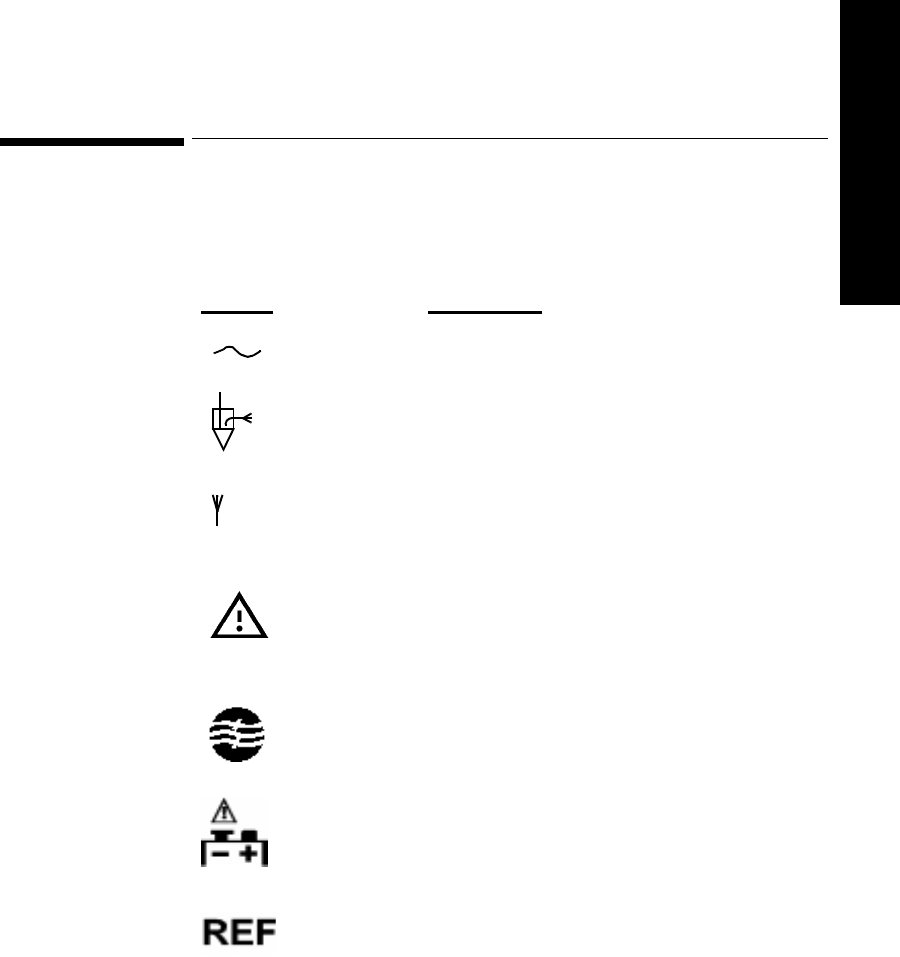
System Symbols
System Safety and Specifications 9-7
9 Safety/Specifications
System Symbols
The following is an explanation of the symbols found on the hardware
components of the Agilent Telemetry System:
Symbol Explanation
AC Line Current.
Active Antenna Combiner.
Antenna Input.
Attention. See instructions for use.
Bandpass Filter
Battery Polarity
Catalog Number

System Symbols
9-8 System Safety and Specifications
Class 2 Equipment
Data In
Data In, Data Out
Data Out
DC Voltage
Date of Manufacture
Do Not Reuse. Use Only Once.
Dispose of properly after use in accordance with
local regulations.
Electrical Input
Electrical Output.
Symbol Explanation
2
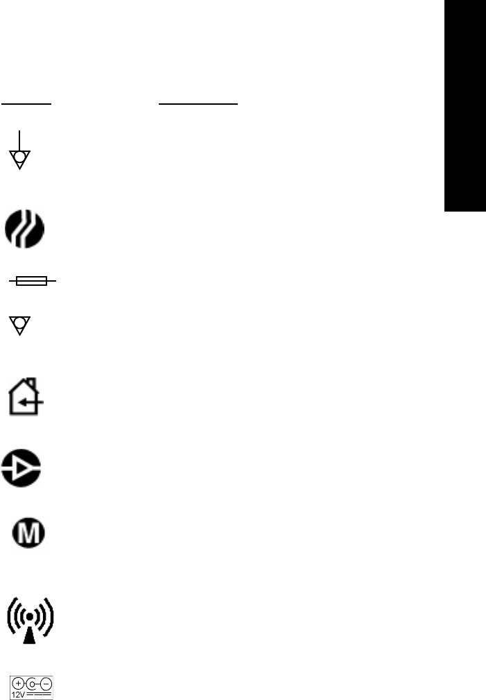
System Symbols
System Safety and Specifications 9-9
9 Safety/Specifications
Equipotential Grounding System.
Frequency Converter
Fuse Input.
Grounding system.
Indoor Use Only
Line Amplifier
Mainframe. For future use.
Non-ionizing Radiation
HP Palmtop Power Polarity
Symbol Explanation
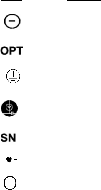
System Symbols
9-10 System Safety and Specifications
Power On/Off
Product Option
Protective Earth (Ground)
Power Tee
Serial Number
Type CF Defibrillation Proof
Class 2 Radio equipment identifier (1999/5/EC)
Symbol Explanation
!

System Symbols
System Safety and Specifications 9-11
9 Safety/Specifications
Type CF Defibrillation Proof
The following symbol indicates that the various instruments connected to the
Agilent Telemetry System are Type CF Defibrillation Proof.
Type CF Defibrillation Proof equipment is designed to have special protection
against electric shocks for intracardiac application (particularly regarding
allowable leakage currents by having an F-type isolated or floating applied part),
and is defibrillator proof.
TYPE CF
DEFIBRILLATION PROOF

Installation and Maintenance Safety
9-12 System Safety and Specifications
Installation and Maintenance Safety
Caution
Installation and setup must be performed by an Agilent Technologies service
representative or designee, except for transmitters and wave viewers purchased
individually. These can be installed by hospital personnel according to
instructions in the Installation and Configuration Guide included in the Service
Training Kit.
At this time, Agilent Technologies will make available on request, and in
English only, such circuit diagrams, component part lists, descriptions,
calibration instructions or other information which will assist the user’s
appropriate qualified technical personnel to repair those parts of the equipment
which are classified by Agilent Technologies to be repairable.
Installation
Environment Follow the instructions below to ensure a completely safe electrical installation.
The environment where the Agilent Telemetry System will be used should be
relatively free from vibration, dust, corrosive or explosive gases, extremes of
temperature, humidity, and so on. For a cabinet mounted installation, allow
sufficient room at the front for operation and sufficient room at the rear for
servicing with the cabinet access door open.
The Agilent Telemetry System operates within specifications at ambient
temperatures between 0ºC (32oF) and 55ºC (131oF). The transmitter ambient
temperature specification is between 0ºC (32oF) and 45oC (113oF). Ambient
temperatures which exceed these limits could effect the accuracy of the
instrument and cause damage to the components and circuits. Allow at least 5
cm (2 inches) clearance around the instrument for proper air circulation.
Grounding To protect hospital personnel, the cabinet of the Agilent Telemetry System must
be grounded. Accordingly, the system is equipped with a detachable 3-wire
cable which grounds the instrument to the power line ground (protective earth)

Installation and Maintenance Safety
System Safety and Specifications 9-13
9 Safety/Specifications
when plugged into an appropriate 3-wire receptacle. If a 3-wire receptacle is not
available, consult the hospital electrician.
Warning
Do not use a 3-wire to 2-wire adapter with this instrument.
Condensation Make sure that during operation, the instrument is free of condensation.
Condensation can form when equipment is moved from one building to another,
thus being exposed to moisture and difference in temperature.
Warning
Possible explosive hazard if used in the presence of flammable anesthetics.
Maintenance
Before beginning monitoring on a patient:
• Check for any mechanical damage.
• Check all the external leads, plug-ins and accessories.
• Check all the functions of the instrument which are needed to monitor the
patient.
• Ensure that the instrument is in good, working order.
Important—
Do not use the Agilent Telemetry Monitoring System for any
monitoring procedure on a patient if you identify features which demonstrate
impaired functioning of the instrument. Contact the hospital biomedical
engineer, or your Agilent Technologies Service Representative.
Warning
Failure on the part of the responsible individual hospital or institution
employing the use of this equipment to implement a satisfactory
maintenance schedule may cause undue equipment failure and possible
health hazards
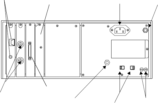
Installation and Maintenance Safety
9-14 System Safety and Specifications
Agilent
Receiver
Mainframe
Rear Panel
The rear panel of the receiver mainframe is shown below. The back of the
mainframe should only be removed by qualified service personnel.
.
SDN Connectors
AC Power
Connector
Fuses
Line Voltage
Selector
Switches
Grounding Lug
Analog Output
Connector
Antenna Port
Not Used CPC Card
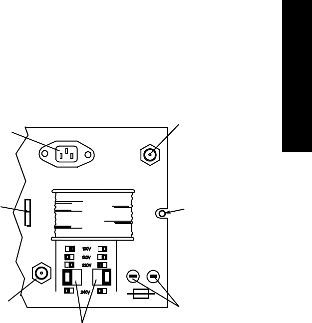
Installation and Maintenance Safety
System Safety and Specifications 9-15
9 Safety/Specifications
This is an enlarged view of the right side of the rear panel:
-
ANTENNA SYSTEM
SIGNAL CONNECTOR
MAX. VOLTAGE +25 V
1
UNFASTEN SCREW
TO REMOVE
PROTECTIVE
COVER
FUSES
VOLTAGE
SELECTOR
SWITCHES
GROUNDING
LUG
2
REMOVE
COVER TAB
FROM SLOT
POWER
CORD
CONNECTOR

Installation and Maintenance Safety
9-16 System Safety and Specifications
Connectors
The connectors on the rear panel of the receiver mainframe are:
Secondary Ground Wire
A secondary ground wire is provided with this instrument to comply with IEC-
60601-1-1. This wire ensures against excessive chassis leakage current in the
event of a single fault in the health care facility’s primary grounding means.
Connector Description
Fuses The input voltage line is protected as follows:
On the M2606-6X001 Power Supply:
• 100/120V 1.6 A fuse (2110-1001)
• 230/240V 0.8 A fuse (2110-1002)
On the M2604-6X000 Power Supply:
• 100/120 V 1AT fuse (2110-0782)
• 230/240V 400 mAT fuse (2110-0536)
On the M1401-6X031:
• 100/120 V 1AT fuse (2110-0782)
• 230/240V 400 mAT fuse (2110-0536)
AC Power Connector This is a 3 pin connector, used to input the
local line voltage. Mainframe plug is a
standard IEC mains inlet receptacle.
Antenna Input Signal
Connector This is a BNC coaxial connector.
SDN Connectors These are upstream and downstream
connectors that connect to the Agilent
monitoring network.
Patient Monitor/Holter
Interface (Analog Output)
Option
High Density 50-pin SCSI-type to connect to
output connector box.
Grounding Lug This is a grounding stud connector, used to
equalize the grounding potential between
products.

Installation and Maintenance Safety
System Safety and Specifications 9-17
9 Safety/Specifications
It is recommended that the secondary ground wire be connected to a ground
source separate from the primary grounding source found in the instrument’s
power source.
Note—
After servicing, be certain to reconnect the secondary ground wire.
Warning
Removal of the secondary grounding wire from the rear of the product
voids the IEC approval.
Lifting the Receiver Mainframe
The weight of the M2604A receiver mainframe is 16.9 kg (37 lbs.). When
carrying the mainframe, hold it firmly from underneath. For safety reasons, it is
strongly recommended that at least two people lift the mainframe. One person
should not attempt it.
Antenna
Amplifiers The antenna amplifiers must be operated only with the Power Supply (AC/DC
Adapter), and must be operated at a minimal distance of 2.43 meters (8 feet)
from the patient.
M26XXA/M14XX Series Antenna Components
For all voltages, use Part Number 0950-3221.
Patient
Monitor/Holter
Interface
Option
If using the optional Patient Monitor/Holter Interface (Analog Output), the
connector box must only be operated with the appropriate power supply) and
must be operated at a minimum distance of 2.43 meters (8 feet) from the patient.
For all voltages, use power supply Part Number 0950-3221.
Preventive Maintenance
Preventive maintenance should be performed by a qualified service person. The
Safety and Performance Tests, and what to do if the equipment does not meet
these specifications, are described in the Agilent Telemetry System Service
Training Kit. Contact your biomedical department if your equipment needs
testing for safety or performance.
Installation and Maintenance Safety
9-18 System Safety and Specifications
End of Life
There is no specific, predetermined end of life to the Agilent Telemetry System
or any of its component products. Agilent Technologies provides service,
support and replacement parts and assemblies throughout the support life of the
products that allow them to be repaired should any component of the system fail.
Please refer to the Agilent Telemetry System Service Training Kit for instructions
on how to obtain service or replacement parts and for instructions on
preventative maintenance. Your local Agilent Technologies sales or service
representative can provide you information regarding the support life of your
products.

Additional Safety Information
System Safety and Specifications 9-19
9 Safety/Specifications
Additional Safety Information
Warning
The equipment is not suitable for use in the presence of a flammable
anesthetic mixture with air or with oxygen or nitrous oxide.
Warning
This device is not to be used during electrosurgery.
Warning
Battery door must be closed during defibrillation.
Warning
Strangulation Hazard! Under no circumstances should any pouch be tied
solely around a patient’s neck.
Warning
Do not use patient cables with detachable lead wires that have exposed male
pins. Electrocution could result if these pins are plugged into AC power.
Software
Hazard
Prevention
The minimization of hazards arising from errors in the software program is
documented in the following reports:
1. Hazard Analysis Report, Revision 1.0, 16 June 1995.
2. Whitebox Test Report, Revision 0.1, 16 June 1995. Includes Safety Fault
Tree Analysis.
3. Quality Demonstration Test, 3 January 1997.
4. Clinical Investigations Report, Revision 1.0, 16 May 1997.
5. White Paper Cover Document, Revision B, 19 August 1998.

System Specifications
9-20 System Safety and Specifications
System Specifications
This section lists the system classification, and the environmental and electrical
power specifications for the hardware components of the system. For complete
specifications, see Agilent Telemetry System Service Training Kit. For full
power specifications for Agilent Wave Viewer, see the Hewlett-Packard 200LX
Palmtop Computer documentation.
System Classification
Class I Equipment
M2604A Receiver Mainframe
Class II Equipment
0950-2038, 0950-3221 Power Supplies
M2611A Battery Extender (Power Supply)
Internally Powered Equipment
M2601A Transmitter (Type CF Defibrillation Proof relative to ECG and SpO2
patient applied parts)
All equipment is Ordinary Equipment, IPX0, and provides continuous operation.
In addition, the M2601A transmitter withstands submersion in 30 cm (1 ft.) of
water for 5 minutes or 10 minutes of water exposure in a shower without
degradation of performance. The transmitter has not been investigated to
IEC 529.

System Specifications
System Safety and Specifications 9-21
9 Safety/Specifications
Environmental Conditions
FOR ALL HARDWARE COMPONENTS OF THE AGILENT TELEMETRY
SYSTEM EXCEPT WAVE VIEWER, AGILENT TRANSMITTERS, AND
REUSABLE PULSE OXIMETRY TRANSDUCERS
Operating
Temperature Range: 0 to 55ºC (32 to 131ºF)
Altitude Range: Up to 4570 m (15,000 ft.)
Humidity Range: 15 to 95% relative humidity
Storage
Temperature Range: -40 to +70ºC (-40 to +158ºF)
Altitude Range: Up to 4570 m (15, 000 ft.)
Humidity Range: 90% relative humidity maximum
For Agilent
Transmitters Operating
Temperature Range: For ECG only, 0-45ºC (32-113º F); For SpO2, 0-37ºC (32-
99º F)
Altitude Range: Up to 4570 m (15,000 ft.)
Humidity Range: 15 to 95% relative humidity, non-condensing
Storage
Temperature with Data Retention: -40 to +70º C (-40 to 158º F)
Altitude Range: Up to 4570 m (15,000 ft.)
Humidity Range: 15 to 95% relative humidity, non-condensing
For Hewlett-
Packard 200LX
Palmtop
Computer
Operating
Temperature Range: 0-50ºC (32-122º F)
Altitude Range: Up to 4570 m (15,000 ft.)
Humidity Range: 90% relative humidity at 40º C (104º F) maximum
Storage
Temperature with Data Retention: 0-60º C (32-140º F)
Altitude Range: Up to 4570 m (15,000 ft.)
Humidity Range: 90% relative humidity at 40º C (104º F) maximum
System Specifications
9-22 System Safety and Specifications
For Reusable
Pulse
Oximetry
Sensors
Operating
Temperature Range: 15-37ºC (50-98.6º F)
Altitude Range: Up to 4570 m (15,000 ft.)
Humidity Range: 95% relative humidity at 37º C (98.6º F) maximum
Storage
Temperature Range: -40 to 70º C (-40 to 158º F)
Altitude Range: Up to 4570 m (15,000 ft.)
Storage Humidity: 95% relative humidity at 65º C (150º F) maximum

System Specifications
System Safety and Specifications 9-23
9 Safety/Specifications
Electrical Power Specifications
Note—
Specifications for earlier releases of the product may vary slightly.
M2601A
Transmitters RF Power Output
Options #001 to #008
+6.5 dBm, +1.6/-2.0 dB (2.8 to 6.5 milliwatts)
For Japan: -3 to 0.8 dBm (0.5 to 1.2 milliwatts) nominal
Option #020
+6.5 dBm, +1.6/-2.5 dB (2.5 to 6.5 milliwatts)
Carrier Frequency Range
Option #001: 406 to 412.5 MHz
Option #002: 412.5 to 421.5 MHz
Option #003: 421.5 to 430 MHz
Option #004: 430 to 440 MHz
Option #005: 440 to 450 MHz
Option #006: 450 to 460 MHz
Option #007: 460 to 470 MHz
Option #008: 470 to 480 MHz
Option #020: 590 to 632 MHz
For M2601A - #ABJ, AR0: Japan only
Option #02J: 412.5 to 421.5 MHz
Option #03J: 421.5 to 430 MHz
Option #05J: 440 to 450 MHz
Radio Channel Spacing
25 kHz minimum
Defibrillator Protection
Transmitter ECG input protected against 400 joules discharge into a 50 Ohm
load
Warning
Battery door must be closed during defibrillation.
System Specifications
9-24 System Safety and Specifications
Batteries
9V Alkaline, Lithium
8.4 Zinc-Air (ECG-only transmitters)
Current Draw
12.0 mA (ECG only); 43.4 mA (ECG and SpO2) typical
M2604A
Receiver
Mainframe
Power Supply
M2604-60001
Input Voltage
100/120/220/230-240 VAC selectable +/- 10%.
Frequency Range
47 to 63 Hz
Power Consumption
For M2604A: 110 VA maximum, 95 VA average, 81 W maximum, 72 W
average with 8 M2603A receiver modules
Controls
Front Panel: Power On/Off
Rear Panel: Line voltage selector.
Indicators
Front Panel: Power On (indicator light and mechanical indicating lines on
POWER button), Instrument Malfunction, Receiver Status (internally via LED).
Connections (rear)
Antenna Input Signal connector (BNC)
Downstream SDN connector
Upstream SDN connector
Analog Output Connector
AC Power Connector (4 selectable line voltages)
Grounding Lug
Radiated Immunity
3 Volts/Meter outside of operating receiver bands

System Specifications
System Safety and Specifications 9-25
9 Safety/Specifications
M2603A
Receiver
Module
Frequency Tuning
Programmable, synthesizer, PLL controlled.
Channel Spacing
25 kHz.
Carrier Frequency Range
Same as M2601A transmitter except no option 020
M2611A
Battery
Extender
Input Voltage
Output Voltage
9.5 to 10 VDC
Output Current Limit
300 mA max
Patient
Monitor Holter
Recorder
Interface
(Analog
Output)
Option J01
Power Module
0950-3221
Input Voltage
100-240 VAC +/- 10%
Frequency Range
47 - 63 Hz.
Power Consumption
33 VA maximum
Analog Output Gain (from output of receiver module)
High-level outputs: 500 + 5%
Low-level outputs: 1 +7%/-6%
U.S.A. 120 VAC +/- 10% (57-63 Hz)
Europe 220-240 VAC +/- 10% (47-53 Hz)
Japan 100 VAC +/- 10% (47-63 Hz)
U.K. 220-240 VAC +/- 10% (47-53 Hz)
Australia 220-240 VAC +/- 10% (47-53 Hz)
S. Africa 220-240 VAC +/- 10% (47-53 Hz)

System Specifications
9-26 System Safety and Specifications
Inoperative Mode (INOP Condition) Output Level
High-level output: 10.8 volts + 1.2 volts
Low-level output: >100 megohms with respect to reference electrode
Delay from Transmitter Input to Analog Output
400 milliseconds max -- Agilent Transmitter
Not intended for use with synchronized cardioversion due to processing delay.
Indicators
Output Connector Box; Status and Power LEDs
Connections
Output Connector Box: Input (50-pin jack); Input (Power Module); Output (8
pairs of 9-pin D connectors)
Analog Output Card: Output (50-pin jack)
Bedside Attenuator: Output (3-conductor phone jack)
Holter Attenuator: Output (set of 5-button connectors)
ECG Bandwidth
M2601A: 0.05 - 40 Hz
Antenna System Specifications
M1406A Line
Amplifier Input Voltage
19 - 40 VDC
RF Frequency Range
406-512 MHz
To ensure proper operation, installation and
setup must be performed by an Agilent
Technologies service representative or designee
according to the instructions in Patient Monitor/
Holter Recorder Interface (Analog Output)
Installation Note (part number M2600-90194).

System Specifications
System Safety and Specifications 9-27
9 Safety/Specifications
Current Requirements
50 mA
Average Power Consumption
About 1.1 Watts.
RF Gain
12.5 dB typical, at 465 MHz
Indicator
Green Power On LED
M1407A
Multiple Unit
Power Supply
Input Voltage
100-240 VAC +/- 10%
Frequency Range
47 - 63 Hz
RF Frequency Range
406-512 MHz
Power Consumption
36 VA maximum
Output Voltage
24 VDC 0 to 1.0 A
Output Current
1.0 A DC
Indicator
Green Power On LED
M1408A Active
Antenna
Combiner
Input Voltage
19 - 32 VDC
Current Requirements
50 mA
Power Consumption
Approximately 1.5 Watts, average
System Specifications
9-28 System Safety and Specifications
RF Frequency Range
406-512 MHz
RF Gain
Antenna: 9.7 dB typical, at 465 MHz
Line: 3.5 dB typical, at 465 MHz.
Indicators
Green LED indicates DC power/signal cable is connected correctly.
Red LED indicates DC power/signal cable is connected incorrectly.
M2606A Line
Amplifier Input Voltage
19-32 VDC
Current Requirements
38 mA, maximum
Power Consumption
0.75 Watts, average
RF Frequency Range
406-650 MHz
RF Gain
12.0 dB typical at 406 MHz
12.7 dB typical at 465 MHz
13.3 dB typical at 611 MHz
13.2 dB typical at 650 MHz
Indicators
Green LED indicates DC power is applied to the RF Output connector.
Yellow LED indicates DC power is applied to the RF Input connector.
M2607A
Multiple Unit
Power Supply
Note—
M2607A specifications cover both power module and power tee.
Input Voltage
CE Mark Power Module 0950-3221: 100-240 VAC +/- 10%
Frequency Range
47-63 Hz

System Specifications
System Safety and Specifications 9-29
9 Safety/Specifications
RF Frequency Range
406-650 MHz
Power Consumption
33 VA maximum
Output Voltage
23 VDC nominal
Output Current
1 Amp maximum (Limited by the circuit breaker in the power tee)
Indicators
Green LED is on when power is present.
M2608A Active
Antenna/
Combiner
Input Voltage
19 - 32 VDC
Input Current
62 mA maximum
Power Consumption
1.1 Watts average (2.0 Watts maximum)
RF Frequency Range
406-650 MHz
RF Gain
Indicators
Green LED indicates DC power/signal cable connected correctly.
Red LED indicates DC power/signal cable connected incorrectly.
Antenna Port 9.7 dB +/- 1.0 dB at 406 MHz
10.2 dB +/- 1.0 dB at 465 MHz
9.7 dB +/- 1.0 dB at 611 MHz
9.7 dB +/- 1.5 dB at 650 MHz
Line Port 3.2 dB +/- 0.7 dB at 406 MHz
3.5 dB +/- 0.3 dB at 465 MHz
3.9 dB +/- 0.7 dB at 611 MHz
4.0 dB +/- 0.7 dB at 650 MHz
System Specifications
9-30 System Safety and Specifications
M2609A
Attenuator Current Carrying Capacity
Maximum DC Voltage: +30 VDC maximum
Maximum DC Current: 1 A maximum
RF Frequency Range:
406-650 MHz
RF Attenuation
1-9 dB in increments of 1 dB, based on option
M2612A
Bandpass
Filter
Current Carrying Capacity
Maximum DC Voltage: 32 Volts
Maximum DC Current: 1 A
Power Requirements
Negligible
RF Frequency Range
#004 430-440 MHz
#005 440-450 MHz
#006 450-460 MHz
#007 460-470 MHz
#034 590-596 MHz
#035 596-602 MHz
#036 602-608 MHz
#037 608-614 MHz
#038 614-620 MHz
#039 620-626 MHz
#040 626-632 MHz
Indicators
Green LED is ON when power is present.
M2616A
External
Frequency
Converter
Input Voltage
100-240 VAC +/- 10%
Frequency Range
47-63 Hz

System Specifications
System Safety and Specifications 9-31
9 Safety/Specifications
Power Consumption
14.0 VA maximum
RF Input Frequency Range
590-632 MHz
RF Output Frequency Ranges
#130 460-502 MHz
#136 454-496 MHz
#142 448-490 MHz
#148 442-484 MHz
#154 436-478 MHz
#160 430-472 MHz
#166 424-466 MHz
Indicators
Green LED is ON when power is present.
Measurement Specifications
ECG Range
Input Dynamic: +/- 9 mV
DC Offset: +/- 320 mV
Cardiotach Alarm (standard ECG only): Central station selectable, in 5 b/min.
increments.
High: 20 - 250 b/min.
Low: 15 - 245 b/min.
Cardiotach Display (standard ECG only): 15 - 300 b/min.
Accuracy
Gain: +/- 5% at 25o C (77o F)
Cardiotach (standard ECG only): +/- 3 beats plus +/- 2% of heart rate for
constant rate input.
At fewer than 15 b/min., the heart rate indication is 0.
Cardiotach Alarm (standard ECG only): +/- 1 b/min., of displayed value
Display
Displayed values are presented in whole numbers.
System Specifications
9-32 System Safety and Specifications
SpO2Measurement Range (Calibration and Display)
0-100%
Accuracy (1 standard deviation)
With Agilent re-usable transducers M1191A, M1192A: 70-100% +/- 2.5%
With Agilent re-usable transducer M1194A: 70-100% +/- 4%
With Nellcor sensors D-25, D-20: 80-100% +/- 3%
Test methods are available from Agilent Technologies upon request.
Resolution
1%
SpO2 Numerics Averaging
10 seconds
Calibration
Automatic self-calibration when device is turned on. The pulse oximeter is
calibrated to display functional saturation.
Pulse Rate Measurement Range (Calibration and Display)
30 - 300 b/min.
Accuracy
+/- 2%
Test methods are available from Agilent Technologies upon request.
Resolution
1 b/min.
Display (at Agilent Wave Viewer only)
Pulse waveform. The waveform is inversely proportional to the pulse volume.

Optional Patient Monitor/Holter Interface (Analog Output) A-1
A Analog Output
A
Optional Patient Monitor/Holter
Interface (Analog Output)
This chapter describes the optional Patient Monitor/Holter Interface (Analog
Output). It includes the following section:
• Overview. . . . . . . . . . . . . . . . . . . . . . . . . . . . . . . . . . . . . . . . . . . . . . . A-2
• Analog Output Bedside Monitor Cables. . . . . . . . . . . . . . . . . . . . . . . A-3
• Lead Placement and Selection . . . . . . . . . . . . . . . . . . . . . . . . . . . . . . A-5
• Controls for Telemetry Setup . . . . . . . . . . . . . . . . . . . . . . . . . . . . . . . A-6
• Functionality with Paced Waves. . . . . . . . . . . . . . . . . . . . . . . . . . . . . A-6
• Inoperative (INOP) Conditions. . . . . . . . . . . . . . . . . . . . . . . . . . . . . . A-7
• Holter Interface . . . . . . . . . . . . . . . . . . . . . . . . . . . . . . . . . . . . . . . . . . A-8

Overview
A-2 Optional Patient Monitor/Holter Interface (Analog Output)
Overview
The optional Patient Monitor/Holter Interface (Analog Output) gives the Agilent
Telemetry System the capability of providing ECG outputs to bedside monitors,
holter monitors, and other recording devices. This option is not available for
telemetry systems with EASI monitoring.
Warning The Patient Monitor/Holter Interface (Analog Output) Option is intended
for display and recording purposes only. The following should not be used
with this option:
Synchronized cardioversion
Intra-aortic balloon pump
Inherent delays in the telemetry transmitter, receiver, and the analog output
processing cause significant time lags between actual ECG occurrence and
the signal required to trigger the defibrillator or intra-aortic balloon pump.
Failure to adhere to this warning could cause serious injury to the patient.
Correct
Labeling To ensure correct lead labeling at the bedside monitor, the following should be
used:
• Correct bedside monitor cable. See the table on page A-4.
• Standard lead placement
• Valid lead selection at the bedside monitor. See “Lead Placement and
Selection” on page A-5.
Not adhering to these recommendations may result in mislabeled leads or an
invalid display.
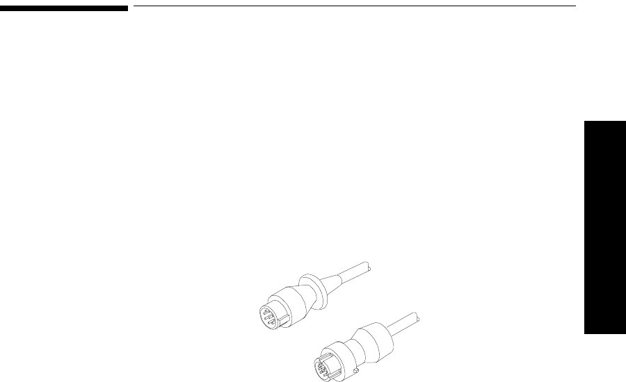
Analog Output Bedside Monitor Cables
Optional Patient Monitor/Holter Interface (Analog Output) A-3
A Analog Output
Analog Output Bedside Monitor Cables
To connect the telemetry transmitter to the bedside monitor via the optional
Patient Monitor/Holter Interface (Analog Output), you will need an analog
output bedside monitor cable.
The end of the cable that connects to the bedside monitor will have either a
small 12-pin connector or a larger 8-pin connector (See the illustration below).
The other end of the cable has a phone plug connector, and it plugs into the
wallplate.
Note—
When using the analog output option for the Agilent Telemetry System,
this cable will replace the bedside monitor patient cable.
There are four different analog output bedside monitor cables. The cable you use
depends upon whether the input connector on your bedside monitor is 8-pin or
12-pin and whether your transmitter leadset is 3- or 5-wire.
The table on page A-5 summarizes the proper cable selection. The 3-wire cables
can be distinguished from the 5-wire cable by the attached label (see page A-5).
The lead set type also determines which are the valid leads to be selected at the
bedside. Appropriate use of each cable type is illustrated on a label attached to
the cable (see page A-5).
8 PIN
12 PIN

Analog Output Bedside Monitor Cables
A-4 Optional Patient Monitor/Holter Interface (Analog Output)
The following table shows all available analog output bedside monitoring
cables.
Caution
To ensure correct lead labeling at the bedside monitor, it is important that you
use the correct bedside monitor cable.
Leadset Bedside Monitor
Cable Connector Analog Output Bedside
Monitor Cable
3-wire leadset 8-pin (large)
12-pin (small)
HP78599AI-#K71
HP78599AI-#K72
5-wire leadset 8-pin (large)
12-pin (small)
HP78599AI-#K73
HP78599AI-#K74

Lead Placement and Selection
Optional Patient Monitor/Holter Interface (Analog Output) A-5
A Analog Output
Lead Placement and Selection
To ensure valid waves with the correct lead label, you must remember to use the
following:
• Standard lead placement (shown on the telemetry transmitter case and in
further detail in Agilent Information Center On-line Help and Agilent
Wave Viewer Help).
• Valid lead selection (performed at the bedside monitor)
The following table summarizes recommended lead placement and selection.
Caution
To ensure correct lead labeling at the bedside monitor, standard lead placement
and valid lead selection must be used. Not adhering to these recommendations
may result in mislabeled leads or an invalid display.
Using Non-
standard
Lead
Placement
With the 3- and 5-wire leadset, you can use non-standard lead placement, but
you must still use a valid lead label selection at the bedside monitor.
This will give you the desired waveform, but it will result in a mislabeled lead at
the bedside monitor.
Leadset Lead Placement Valid Lead Selection on
Bedside Monitor
3-wire Standard II
5-wire Standard II, MCL

Controls for Telemetry Setup
A-6 Optional Patient Monitor/Holter Interface (Analog Output)
Controls for Telemetry Setup
The interaction with ECG depends on how the system is installed. If it is
installed so that you can make changes from the Agilent Information Center, the
interface for lead and size selection is the same as described in “Changing Lead/
Label” on page 2-8. If not, make adjustments at the bedside monitor.
Functionality with Paced Waves
In order for paced waves to be processed correctly by bedside monitors using the
analog outputs, the pace pulses must be artificially reconstructed and inserted
into the analog output signals. The synthesized pace pulse is very narrow and
may not be visible at the bedside display, depending on the type of monitor
used.
Warning
To ensure proper cardiotach performance, diagnostic bandwidth (filter off)
should be selected at the bedside monitor when monitoring paced patients
with a transmitter.

Inoperative (INOP) Conditions
Optional Patient Monitor/Holter Interface (Analog Output) A-7
A Analog Output
Inoperative (INOP) Conditions
With the Patient Monitor/Holter Interface (Analog Output) Option, the
following telemetry inoperative (INOP) conditions will appear as a LEADS OFF
message at the bedside monitor.
1. LEADS OFF
2. NO SIGNAL
3. TEL CANNOT ANALYZE
4. REPLACE BATTERY
5. INTERFERENCE
6. RECEIVER MALF
7. NO RECEIVER
8. TRANSMITTER MALF
9. ECG EQUIP MALF
10. TRANSMITTER OFF
11. INVALID LEAD SET
If telemetry controls are located at the bedside monitor, (see “Controls for
Telemetry Setup” on page A-6, these INOPS appear as a LEADS OFF message
at the Agilent Information Center.
Note—
See “Telemetry Alarm & INOP Summary” on page 2-18 for information
about the specific alarm messages.

Holter Interface
A-8 Optional Patient Monitor/Holter Interface (Analog Output)
Holter Interface
If you are using a holter monitor, it should be connected to a holter wallplate.
Warning
Using a holter wallplate to interface to a bedside monitor could result in
mislabeled leads.

Accessories and Ordering Information B-1
B Ordering Information
B
Accessories and
Ordering Information
This appendix provides a list of telemetry accessories you can order through
your Agilent Technologies representative. For a list of sales offices, see
“Appendix D. Sales and Support Offices”.
Accessories for Agilent Transmitters
Description Agilent Part
Number
Battery
• 9 V Lithium (box of 10)
• 8.4 V Zinc-Air (box of 12) - for use with ECG-
only transmitters only
ULBU9VLJ
40455A
3-wire ECG Lead Set
• Snap, AAMI for M2601A, 0.7 m (30 inch)
• Grabber, AAMI for M2601A, 0.7 m (30 inch)
• Snap, IEC for M2601A, 0.7 m (30 inch)
• Grabber, IEC for M2601A, 0.7 m (30 inch)
M2590A
M2591A
M2594A
M2595A
5-wire ECG Lead Set
• Snap, AAMI for M2601A , 0.7 m (30 inch)
• Grabber, AAMI for M2601A , 0.7 m (30 inch)
• Snap, IEC for M2601A, 0.7 m (30 inch)
• Grabber, IEC for M2601A, 0.7 m (30 inch)
M2592A
M2593A
M2596A
M2597A
Combiner Shield
•3-wire
•5-wire M2598A
M2599A
ECG Electrodes
• High Performance Foam,1/pack, 200/case
• High Performance Foam,3/pack, 300/case 14445A
14445C

B-2 Accessories and Ordering Information
Oxisensor II™ is a trademark of Nellcor® Incorporated.
Note—
Disposable transducers are not available as Agilent parts in the USA or
Canada. In those countries, contact Nellcor® Incorporated directly at 1-800-635-
5267 or 1-888-744-1414.
ECG Electrode Kit M2202A
ECG Electrode Kit
• 30 electrodes
• Foam, 5/pack, 300/case
• Foam, 30/pack, 300/case
40489E
40493D
40493E
Transmitter Pouch
• Disposable, 50 /case
• Disposable, 200/case 9300-0768-050
9300-0768-200
SpO2 Transducer
• Agilent Reusable Adult Finger
• Agilent Reusable Pediatric/Small Adult Finger
• Agilent Reusable Adult/Pediatric Ear Clip
M1191A
M1192A
M1194A
Wristband M1627A
Nellcor Oxisensor™
•D-20
•D-25 M1903A/B
M1904A/B
Adapter Cable for use with Nellcor Oxisensor™
disposable transducers M1943A
Description Agilent Part
Number

System Releases C-1
C System Releases
C
System Releases
This appendix summarizes the enhancements made during each release of the
Agilent Telemetry System. Releases are identified by date and revision codes.
For assistance in identifying the revision codes of your equipment, see your
service department. Also in this appendix you’ll find summary notes about some
of the system enhancements made in previous releases.
System Releases
Release C
(July ‘00) Revision Codes
• Agilent Transmitter: B.00
• Agilent Wave Viewer: B.00
• Agilent Mainframe: E.00
Enhancements
• 12-lead EASI monitoring
•SpO
2 parameter Auto ON
• Rebranding of current products from Hewlett-Packard to Agilent
Technologies
Release B
(February
‘00)
Revision Codes
• HP Viridia Transmitter: A.03
• HP Viridia Wave Viewer: A.02
• HP Viridia Mainframe: D.03
Enhancements
• Dual RF Frequency Bands
• HP Viridia Battery Extender
• HP Viridia Transmitter Battery Life Improvement
• HP Viridia Transmitter Water-Resistant Electronics
•Manual SpO
2 Measurement from Transmitter without HP Wave Viewer
System Releases
C-2 System Releases
August ‘98 Revision Codes
• HP Viridia Transmitter: A.02
• HP Viridia Wave Viewer: A.02
• HP Viridia Mainframe: D.03
Enhancements
• HP Viridia Wave Viewer as Patient Assessment Tool
• HP Viridia Transmitter Cross-infection Prevention Available
• Initial SpO2 Sample Rate changed from 1-minute to manual
• Battery Life Improvement
November
‘97 (US only) Revision Codes
• HP Viridia Transmitter: A.01
• HP Viridia Wave Viewer: A.01
• HP Viridia Mainframe: D.02
Enhancements
•SpO
2 Parameter Default OFF at Admit
•SpO
2 Alarms Non-latching
• Battery Life Improvement
• Zinc-Air Batteries with ECG-only HP Viridia Transmitters
May ‘97
(US Only) Revision Codes
• HP Viridia Transmitter: A.00
• HP Viridia Wave Viewer: A.00
• HP Viridia Mainframe: D.01
Enhancements
• First release of system
• HP Viridia Transmitter with ECG-only and ECG/SpO2 measurements
measurements)
• HP Wave Viewer as Productivity Tool

Release C Enhancement Details
System Releases C-3
C System Releases
Release C Enhancement Details
EASI
12-lead
Monitoring
The EASI option allows you to derive all 12 standard ECG leads, using a 5-wire
leadset cable and special electrode placement. There are two versions of the
transmitter available: 12-lead EASI ECG only and 12-lead EASI ECG with
SpO2.
When compared to standard 5-lead ECG, the EASI 12-lead ECG documents ST
changes with a full 12-lead ECG. EASI electrode placement is easier to locate,
more convenient, and provides more stable electrode positions than standard and
modified 12-lead ECG. This translates to time and cost savings for the hospital
and increased patient comfort and mobility.
What You
Need to Know • EASI 12-lead ECG is only for use on adult and pediatric patients.
• The EASI transmitters require that EASI lead placement is used. Refer to
the online Help on the Agilent Information Center or to the diagram on
page C-5 for lead placement information.
• EASI transmitters have a new overlay specific to the EASI leadset which
includes a chest diagram with the EASI lead positions. To aid in
identification, the background color of the overlay is purple.
• The derived 12-lead ECG is intended for monitoring ST changes and
arrhythmias.
• Analog output is not supported. The INOP “LEADS OFF” is displayed.
• Any telemetry EASI bed must be arrhythmia-monitored. If arrhythmia is
not on, the INOP “Arrhy Required” is shown and no waves or parameters
are displayed.

Release C Enhancement Details
C-4 System Releases
During
INOPs If one of the derived EASI leads has an INOP condition (i.e., LEADS OFF), a
flat line is displayed. After ten seconds, the directly acquired EASI AI, AS, or
ES lead (depending on which is available) is displayed with the label “ECG” and
is analyzed by the arrhythmia system. This feature is called “fallback.” To
summarize, whenever there is an INOP condition with EASI, the arrhythmia
algorithm performs a Relearn, using the available “raw” leads.
Note—
If there is artifact in the ECG waves or a CANNOT ANALYZE ECG
INOP condition, you can use the three EASI leads to troubleshoot.
1. Click 12-Lead ECG on the Patient Window, then on 3 EASI Leads.
2. The three directly acquired EASI leads will be displayed so that you can
determine which electrodes are causing the problem and need to be
replaced.
Warning Since Relearn happens automatically, if learning takes place during
ventricular rhythm, the ectopics may be incorrectly learned as the normal
QRS complex. This may result in missed detection of subsequent events of V-
Tach and V-Fib. For this reason, you should:
1. Respond tpromptly o the INOP message [for example, re-connect the
electrode(s)].
2. Ensure that the arrhythmia algorithm is labeling beats correctly.

Release C Enhancement Details
System Releases C-5
C System Releases
EASI Electrode
Placement
with a
5-wire leadset
for 12-lead
ECG
Electrode labels and colors are given for AAMI norm and in square brackets [-]
for IEC norm.
E - Brown [IEC: White] electrode - place on the lower sternum at the level of
the fifth intercostal space.
A - Red [IEC: Green] electrode - place on the left midaxillary line at the same
level as the E electrode.
S - Black [IEC: Yellow] electrode - place on the upper sternum.
I - White [IEC: Red] electrode - place on the right midaxillary line at the same
level as the E electrode.
Reference -Green [IEC: Black] electrode - place ground electrode anywhere
(usually below the 6th rib on right hip).
Please note... • When placing electrodes, be careful to place the electrodes as accurately
as possible or the derived leads may be incorrect. If necessary, the AI
electrodes may be shifted down or up , or the ES electrodes may be
shifted left or right, but the AI and ES electrodes must still be at right
angles. The following guidelines should be followed:
– When plaster or therapeutic equipment restricts electrode placement,
the E and S electrodes can be moved in parallel to the patient’s right,
but keep this move as small as possible.
1
2
3
4
5
E
IA
S
REF
Release C Enhancement Details
C-6 System Releases
– When pulmonary problems restrict electrode placement, the A and I
electrodes can be moved down or up in parallel. Moving the
electrodes down produces better measurements than moving them
up.
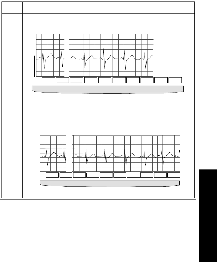
Release C Enhancement Details
System Releases C-7
C System Releases
Viewing
EASI Leads You can use the Wave Viewer to view the directly acquired or “raw” EASI leads
(AI, AS, ES) at the patient’s side. The reconstructed leads (I, II, III, aVR, aVL,
aVF, V1, V2, V3, V4, V5, and V6) are not available at the Wave Viewer.
Changes made to lead selection at the Wave Viewer are not sent to the Agilent
Information Center.
Task Summary View the directly acquired EASI leads with the Wave Viewer by performing the
following steps:
Step Action
1 From the Wave Viewer Main Screen, press EASI.
2 Select the lead. Lead selection affects only the Wave Viewer
display; selection made at the Wave Viewer is not reflected at
Agilent Information Center.
.
72
96
PULSE
F1 F2 F3 F4 F5 F6 F7 F8 F9 F10
% SpO
2
1mV
Help EASI SpO2/
Pleth Setup
SpO2 Config Est
HR
EASI AS
SpO2
Estimate
1mV
RightEnd
F1 F2 F3 F4 F5 F6 F7 F8 F9 F10
EASI AS
Help AI AS ES
Inc
Size Size
Dec
Est
HR Main
Screen
Release C Enhancement Details
C-8 System Releases
Additions to
Hard INOP
Messages at
Central
A hard INOP has an audible tone, and monitoring and alarms are disabled.
When using the new EASI transmitter, the following hard INOP messages have
been added to the normal telemetry INOPs:
LEADS OFF (el. X) Where X is the electrode that is off (i.e., el. E, el. I, el.
A, or el. S). If one EASI electrode is off, no calculation
can be made. A raw EASI waveform labeled “ECG” is
displayed until the electrode is reattached. If 3 or more
electrodes are off, no electrode is specified in the
message (e.g., LEADS OFF).
ARRHY REQUIRED Arrhythmia is not turned on for this bed. Arrhythmia
must be turned on when EASI is used. No waves or
parameters are displayed.
ECG EQUIP MALF The EASI transmitter is being used with equipment that
is not capable of accepting EASI data.
INVALID LEADSET This INOP occurs when a three-wire lead set is used
and connected to a patient. A 5-wire leadset must be
used with an EASI transmitter.
WaveViewer
INOP
Change
ECG Equipment
Malfunction An EASI transmitter:
• does not have a 5-wire leadset attached
• does not have the 5-wire leadset inserted fully
• has no leadset attached
• has a 3-wire leadset attached.

Release C Enhancement Details
System Releases C-9
C System Releases
ST Segment
Monitoring
with EASI
ST/AR ST analysis for EASI derived transmitters is done on all 12 leads. The
value presented in the patient sector and Patient Window is “STindx”. STindx is
a summation of three ST segment measurements, using the leads that can
indicate ST segment changes in the different locations of the heart:
– anterior lead V2
– lateral lead V5
– inferior lead aVF
Note—
Studies have validated the maximal EASI derived ST measurements on
male and female patients with ages from 33 to 82, heights 147 to 185 cm (58 to
73 in), weights 53 to 118 kg (117 to 261 lb) and height-to-weight ratios of 1.41
to 2.99 cm/kg (0.25 to 0.54 in/lb).
No ST analysis is done when an electrode falls off. ST analysis is switched off
automatically and the monitor displays a raw EASI waveform labeled “ECG”.
When more than one ST parameter is in alarm, only one alarm message displays.
Caution
Be sure not to duplicate the lead labels. This can result in incorrect ST values
being displayed for those leads.
Multilead
Alarms with
EASI
For multilead alarms when using an EASI transmitter, an alarm is generated if
two or more ST leads exceed the alarm limits. The default setting is +/-1.0. The
alarm message indicates the two leads that are in greatest violation of the limits,
for example, “**MULTI ST AVR, V6”. If another lead becomes deviant, the
message changes but it is considered the same alarm (no new alarm sounds and
it is not listed as a new event).

SpO2 Parameter Auto ON
C-10 System Releases
SpO2 Parameter Auto ON
The SpO2 parameter is automatically turned on at the Agilent Information
Center if a manual SpO2 measurement is initiated at the transmitter while in
Manual mode or the SpO2 transducer is inserted into the transmitter while the
transmitter is in continuous SpO2 mode.
When a patient is discharged and the transmitter is in Continuous mode, the
SpO2 parameter is turned off. To reactivate the SpO2 Auto On feature from the
transmitter, remember to do one of the following when a patient is discharged:
– remove the SpO2 cable from the transmitter, wait 15 seconds, then
reinsert the cable
or
– reset the transmitter to Manual mode.
Note—
The SpO2 Auto On feature only needs to be reactivated when the
transmitter is in Continuous mode at discharge.
Note—
SpO2 can always be turned on and off at the Agilent Information Center.
Other
Changes • Various changes have been made to this document to reflect the
rebranding of current products from Hewlett-Packard to Agilent
Technologies.
• Compliance with the Council Directive of 1999/5/EC of 9 March 1999
concerning radio equipment and telecommunications terminal equipment
has been added.

Sales and Support Offices D-1
D Sales Offices
D
Sales and Support Offices
For more information, please call your local Agilent Technologies sales office
listed in your telephone directory or an Agilent Technologies regional office
listed below for the location of your nearest sales office.
Healthcare Solutions Group Headquarters
Agilent Technologies, Inc.
3000 Minuteman Road
Andover, MA 01810
1-800-934-7372
Canada
Agilent Technologies, Inc.
5150 Spectrum Way
Mississauga, Ontario L4W 5G1
Canada
1-800-291-6743
Europe
Agilent Technologies, Inc.
Healthcare Solutions Group
Herrenberger Strasse 110-140
71034 Boeblingen
Germany
(+49) 7031 464 5151
Fax: (+49) 7031 464 4096
D-2 Sales and Support Offices
Medical Distribution
Europe/Middle East/Africa
Rue de Veyrot, 39
1217 Meyrin 1
Geneva, Switzerland
(+41) 22 780 6111
Latin America
Agilent Technologies, Inc.
5200 Blue Lagoon Drive
9th Floor
Miami, FL 33126
(305) 267-4220
Asia Pacific Headquarters
Agilent Technologies, Inc.
24F Cityplaza One
1111 King’s Road
Taikoo Shing, Hong Kong
(+852) 3197 7777

Sales and Support Offices D-3
D Sales Offices
Country Sales Offices
United States:
Massachusetts Headquarters
1-800-934-7372
Canada:
1-800-291-6743
Latin America
Miami Headquarters
(305) 267-4220
Brazil:
5511-7297 3719
Chile:
562 290 3381
Colombia:
571 622 3403
Mexico:
525 258 4137
Puerto Rico:
787 289 8903
Venezuela:
582 207 8261
Asia Pacific
Hong Kong Headquarters:
(+852) 3197 7777
Australia:
+61 1800 033 397
China:
+86-10 6564 5500
India:
+91-11 682 6415
D-4 Sales and Support Offices
Japan (Tokyo):
+81-3 5802 5910
Japan (Suidobashi):
Customer Service Center
+81-3 5802 5836
Korea:
+82-2 1588 5522
Singapore/Southeast Asia:
+65 377 1688
Taiwan:
+886-2 8712 2899
Europe
Medical Distribution:
Europe/Middle East/Africa
(+41) 22 780 6111
Austria:
+43 1 25 125-0
Belgium/Luxembourg:
(+32) 2 778 31 11
Finland:
+358 10 8551
France:
(+33) 1 69 29 43 43
Germany:
(01 80) 5 32 62 77
Italy:
+39 02 92 608 1
Netherlands:
(+31) 20 547 63 38
Poland:
(+48) 22-608-74 30

Sales and Support Offices D-5
D Sales Offices
Portugal:
+351 1 482 8730
Russia:
+7 095 916 9811 ext. 3873
Spain:
(+34) 91 631 3100
Sweden:
+46 8 506 486 00
Switzerland:
+41 1 735 91 11 (German Swiss)
(+41) 22 780 41 11 (Suisse Romande)
United Kingdom:
(+44) 700 244 5368
D-6 Sales and Support Offices

Index-1
Index
A
alarms
SpO2,4-20
ST, 3-8
ST messages, 3-10
turning off SpO2,4-17
analog output, A-2
bedside monitor cables, A-3
INOPs, A-7
lead placement and selection, A-5
making adjustments, A-6
use with paced waves, A-6
antenna amplifiers, 9-17
artifact
muscle and movement, 2-16
automatic shutoff
Agilent transmitter, 1-13
B
batteries
Zinc-Air, 1-14
battery
disposal, 1-16
inserting
Agilent Transmitter, 1-17
life, 1-16
optimizing life, 1-15
battery extender, 1-9
connecting, 1-10
disconnecting, 1-11, 1-17
C
cleaning
battery extender, 7-4
ECG patient cables, 7-16
palmtop, 7-15
receiver mainframe, 7-3
SpO2 transducers, 7-18
telemetry system, 7-2
Agilent transmitter, 7-4
configuration
changing, 8-5
settings, 8-3
connectors
receiver mainframe, 9-16
D
dropouts, 2-15
E
EASI
lead placement, C-5
more details, 2-6, C-3
ST, 3-2
ECG
accessories, B-1
changing lead/labels, 2-8
checking signal quality, 6-4
interference, 2-16
lead placement, 2-2, 2-4
telemetry monitoring, 2-5
ECG noise
troubleshooting, 2-16
ECG patient cables
cleaning, 7-16
ECG waves
changing size, 2-8
extended monitoring, 2-13
F
fallback
EASI, 2-12
multilead analysis, 2-12
singlelead analysis, 2-12

Index-2
frequency
changing transmitter, 8-8
G
grounding
secondary ground wire, 9-16
telemetry, 9-12
H
heart rate
estimating using Wave Viewer, 6-8
Holter Interface
see analog output, A-1
I
INOP messages
SpO2,4-20
ST, 3-8
telemetry, 2-19
Wave Viewer, 6-15
L
labels
changing ECG, 2-8
lead sets
capabilities, 2-2, 2-8
disconnecting an Agilent transmitter, 1-8
leads
changing, 2-8
changing via Wave Viewer, 6-7
light pipe, 5-9, 5-11
M
messages
SpO2,4-20
ST, 3-10
telemetry INOPs, 2-19
Wave Viewer INOPs, 6-15
monitoring
during leads off, 2-12
N
noise
eliminating, 2-16
nurse call, 1-12
P
paced patients
using analog outputs, A-6
palmtop
cleaning, 7-15
connecting transmitter to, 5-9
keys, 6-2
turning off, 6-13
Patient Button
See Transmitter Button, 1-12
Patient Monitor/Holter Interface
See analog output
pouch, 1-13
R
receiver mainframe, 1-21
cleaning, 7-3
connectors, 9-16
rear panel, 9-14
retaining settings, 1-22
turning on/off, 1-21
RF INOPs, 2-15
RF interference, 2-16
S
signal strength, 2-15
Smart Limits
ST, 3-9
SpO2
accessories, B-2
alarm and INOP messages, 4-20
applying transducers, 4-11
changing the sample rate, 6-10
checking signal quality with Wave Viewer, 6-9
making measurements, 4-6

Index-3
making STAT measurements, 6-11
manual measurement from the transmitter, 1-
12
manual measurement from transmitter, 1-9
obtaining accurate measurements, 4-7
selecting transducers, 4-10
telemetry monitoring, 4-4
transducers, 4-9
turning alarms on/off, 4-19
turning parameter on/off, 4-17
turning pulse parameter on/off, 4-19
ST
adjusting measurement points, 3-5
alarm adjustments, 3-9
alarm and INOP messages, 3-10
alarms, 3-8
analysis, 3-2
measurement, 3-3
smart limits, 3-9
turning on/off monitoring, 3-7
viewing data, 3-4
standby mode, 2-11
sterilization
ECG cables & leads, 7-18
T
telemetry
accessories, B-1
changing ECG wave size, 2-8
changing frequency, 8-6, 8-8
changing lead/label, 2-8
cleaning, 7-2
dropouts, 2-15
ECG monitoring, 2-5
grounding, 9-12
Agilent Transmitter, 1-7
INOP messages, 2-19
muscle and movement artifact, 2-16
noise, 2-16
on/off, 1-23
optimizing performance, 2-14
Patient Monitor/Holter Interface, 9-17
preparing for ECG monitoring, 2-5
preparing for SpO2 monitoring, 4-4
receiver mainframe, 9-14
retaining settings, 1-22
RF INOPs, 2-15
RF interference, 2-16
signal strength, 2-15
SpO2 monitoring, 4-2
standby mode, 2-11
suspending monitoring, 2-11
system components, 1-4
Telemetry, On/Off, 1-23
transducers, 4-9
adult finger, 4-13
applying, 4-11
cleaning, 7-18
ear clip, 4-15
selecting, 4-10
small adult/pediatric, 4-14
transmitter
Agilent, 1-7
automatic shutoff, 1-13
battery, 1-13
battery disposal, 1-16
battery life, 1-16
button, 1-12
button on/off, 2-10
changing frequency, 8-8
cleaning, 7-4
connecting palmtop to, 5-9
inserting batteries
Agilent Transmitter, 1-17
receiver mainframe, 1-21
storage, 1-14, 1-15
transmitter button
turning on/off, 2-10
troubleshooting
ECG noise, 2-16

Index-4
SpO2,4-7
W
water resistance, 1-12
Wave Viewer
adjusting ECG size, 6-7
batteries, 5-13
changing leads, 6-7
changing the sample rate, 6-10
checking SpO2 signal quality, 6-9
controls, 6-2
estimating heart rate, 6-8
exiting, 6-13, 6-14
indications for use, 5-2
INOP messages, 6-15
installing, 5-7
using to make STAT measurements, 6-11
using to view EASI leads, 6-6, C-7
using to view other leads, 6-5
waves
changing size on display/recordings, 2-8
changing size via Wave Viewer, 6-7
Z
Zinc-Air batteries, 1-14