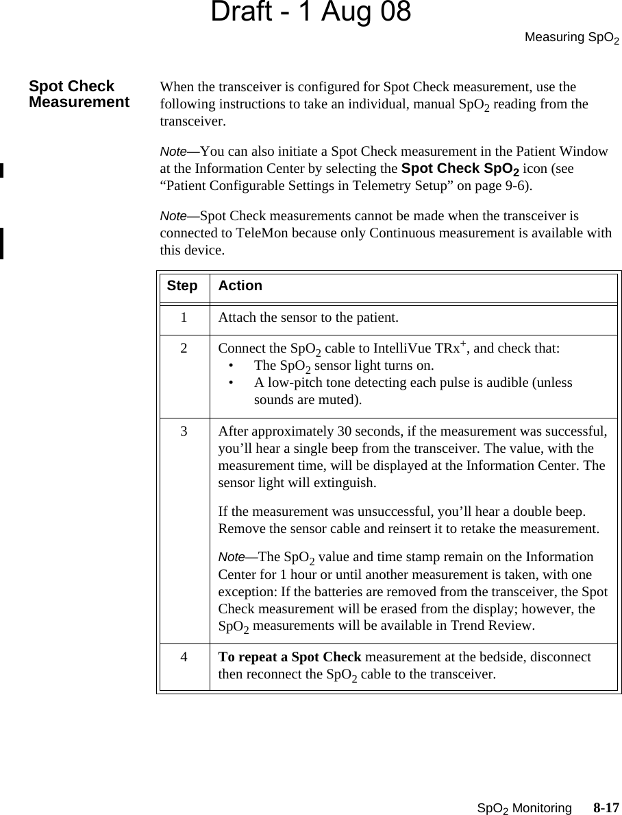
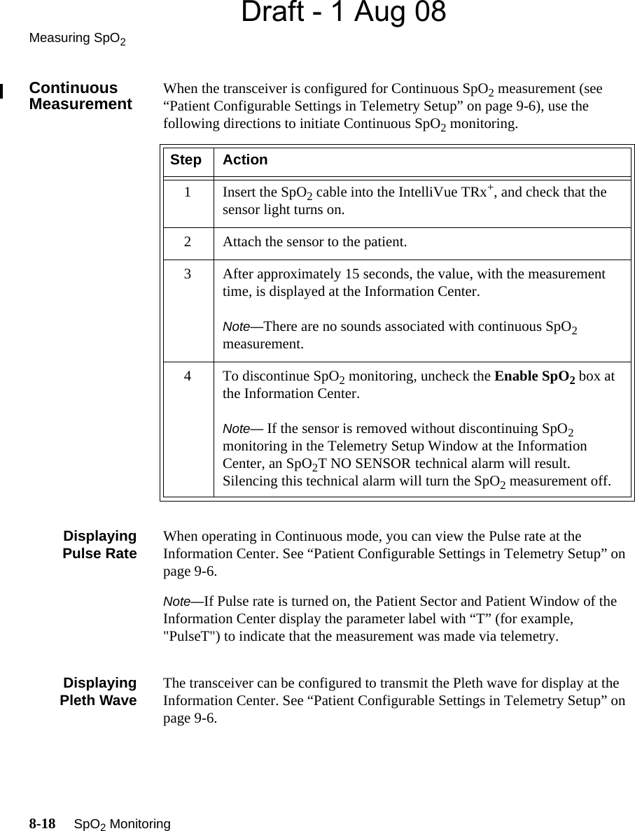
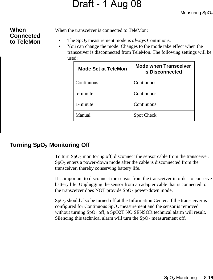
Philips Medical Systems North America SRRAV1 IntelliVue SRR, Short Range Radio Adapter User Manual M4841 91001
Philips Medical Systems North America Co. IntelliVue SRR, Short Range Radio Adapter M4841 91001
UserManual.wiki
>
Philips Medical Systems North America
>
SRRAV1 User Manual
Users Manual
Navigation menu
Upload a User Manual
Namespaces
Wiki Guide
HTML
PDF
Info
Views
User Manual
Discussion / Help
Navigation

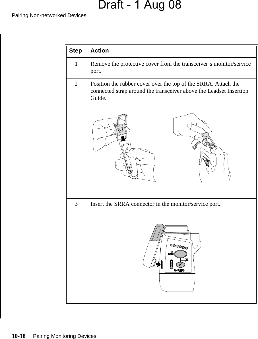
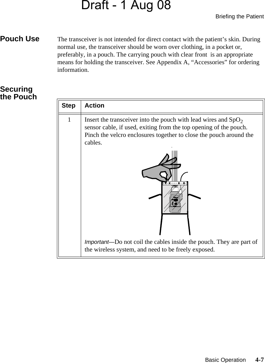
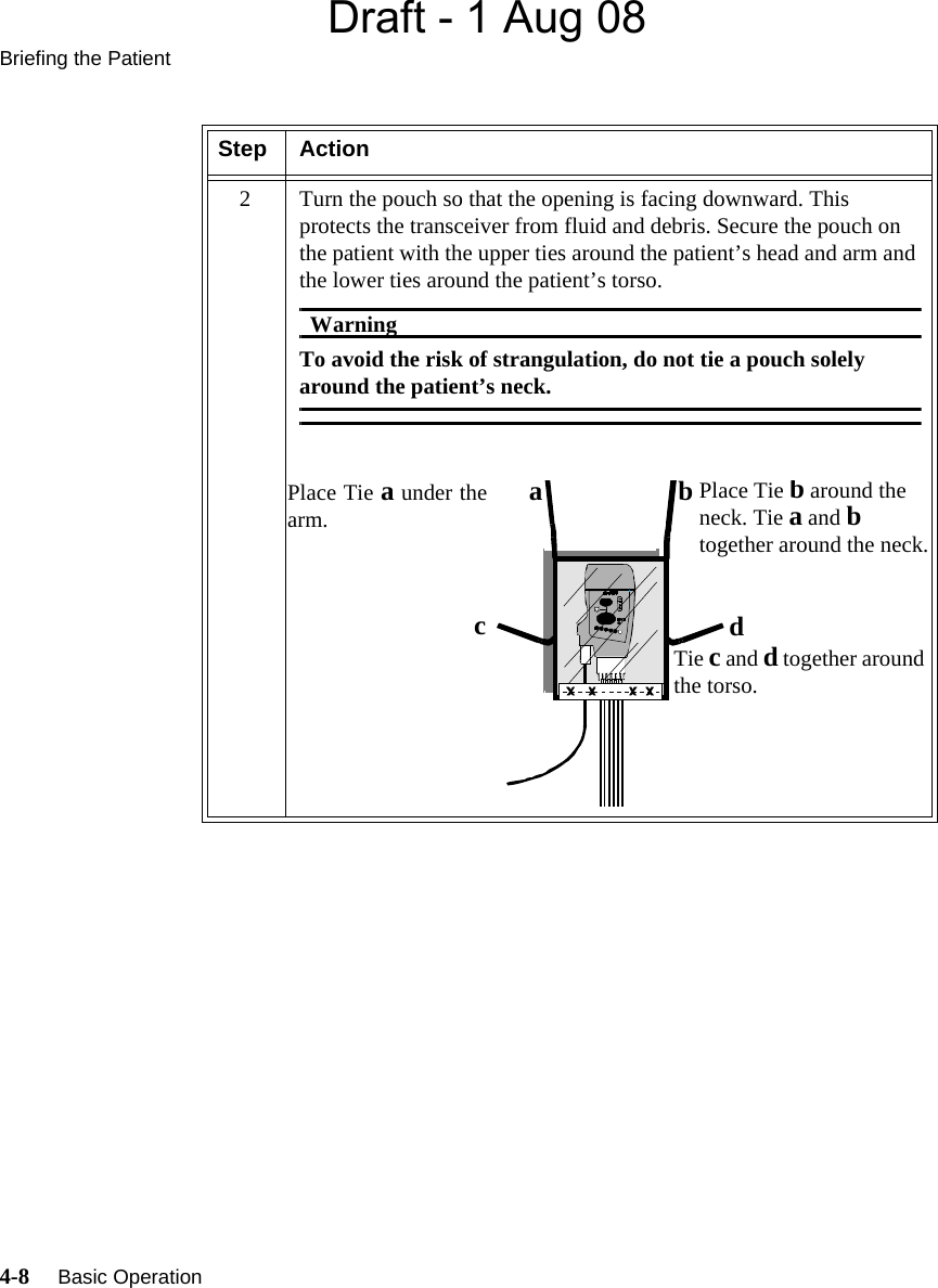
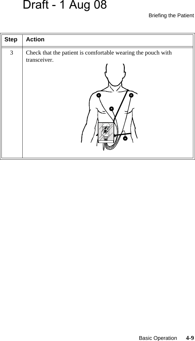
![Draft - 1 Aug 08ST/AR Arrhythmia Product Safety 2-9WarningWarningLearningIf you initiate learning during ventricular rhythm, the ectopics can be incorrectly learned as the normal QRS complex. This can result in missed detection of subsequent events of V-Tach and V-Fib.WarningWarningRelearningArrhythmia relearning is initiated whenever the transceiver is powered down for one minute or longer or whenever it is directly connected/disconnected to an IntelliVue MP5 Patient Monitor. Be sure to check your patient’s arrhythmia annotation for accuracy whenever relearn has occurred.Since Relearn happens automatically, if learning takes place during ventricular rhythm, the ectopics can be incorrectly learned as the normal QRS complex. This can result in missed detection of subsequent events of V-Tach and V-Fib. For this reason, you should:1. Respond promptly to any technical alarm.2. Ensure that the arrhythmia algorithm is labeling beats correctly.When using EASI ECG monitoring, Relearn happens automatically when there is a LEADS OFF technical alarm. If learning takes place during ventricular rhythm, the ectopics can be incorrectly learned as the normal QRS complex. This can result in missed detection of subsequent events of V-Tach and V-Fib. Be sure to check the beat labels and initiate a relearn to correct.1. Respond to the technical alarm [for example, reconnect the electrode(s)].2. Ensure that the arrhythmia algorithm is labeling beats correctly.](https://usermanual.wiki/Philips-Medical-Systems-North-America/SRRAV1/User-Guide-985801-Page-31.png)


![Draft - 1 Aug 08ST/AR Arrhythmia AlgorithmST/AR Arrhythmia Monitoring 7-3WarningWarningRelearningArrhythmia relearning is initiated whenever the transceiver is powered down for one minute or longer or whenever it is directly connected/disconnected to an IntelliVue MP5 Patient Monitor. Be sure to check your patient’s arrhythmia annotation for accuracy whenever relearn has occurred.Since Relearn happens automatically, if learning takes place during ventricular rhythm, the ectopics can be incorrectly learned as the normal QRS complex. This can result in missed detection of subsequent events of V-Tach and V-Fib. For this reason, you should:1. Respond promptly to any technical alarm.2. Ensure that the arrhythmia algorithm is labeling beats correctly.When using EASI ECG monitoring, Relearn happens automatically when there is a LEADS OFF technical alarm. If learning takes place during ventricular rhythm, the ectopics can be incorrectly learned as the normal QRS complex. This can result in missed detection of subsequent events of V-Tach and V-Fib. Be sure to check the beat labels and initiate a relearn to correct.1. Respond to the technical alarm [for example, reconnect the electrode(s)].2. Ensure that the arrhythmia algorithm is labeling beats correctly. For Paced PatientsWarningWarningSome pace pulses can be difficult to reject. When this happens, the pulses are counted as a QRS complex, and could result in an incorrect HR and failure to detect cardiac arrest or some arrhythmias. Keep pacemaker patients under close observation.](https://usermanual.wiki/Philips-Medical-Systems-North-America/SRRAV1/User-Guide-985801-Page-131.png)