Philips Medical Systems North America SRRAV1 IntelliVue SRR, Short Range Radio Adapter User Manual M4841 91001
Philips Medical Systems North America Co. IntelliVue SRR, Short Range Radio Adapter M4841 91001
Users Manual

Draft - 1 Aug 08
Instructions for Use
IntelliVue TRx/TRx+ Transceivers
for the ITS4840A/ITS4850A IntelliVue Telemetry
System
Part Number: 4535 640 87761
Printed in the U.S.A. September 2008
First Edition
Notice (ITS4842A, TRx4841A)
These devices comply with part 15 of the FCC Rules.
Operation is subject to the following two conditions: (1)
these devices may not cause harmful interference, and
(2) these devices must accept any interference received,
including interference that may cause undesired
operation.
Notice (ITS4852A, TRx4851A)
These devices comply with part 15 of the FCC Rules,
ETSI, RSS-210, and other international radio standards
that govern operation in the ISM band. Operation is not
subject to WMTS rules.

Draft - 1 Aug 08
ii
Notice Document number: 453564087761, First Edition
Printed in the USA.
© Copyright 2008 Koninklijke Philips Electronics N.V. All Rights Reserved.
Reproduction in whole or in part is prohibited without the prior written
consent of the copyright holder.
Philips Medical Systems Nederland B.V. reserves the right to make changes in
specifications and/or to discontinue any product at any time without notice or
obligation and will not be liable for any consequences resulting from the use of
this publication.
Equipment specifications are subject to alteration without notice. All changes
will be in compliance with regulations governing manufacture of medical
equipment.
OxiCliq® and OxiMax® are registered trademarks of Nellcor Incorporated.
Duracell® is a registered trademark of Duracell International Incorporated.
Manufacturer Philips Medical Systems
3000 Minuteman Road
Andover, MA 01810-1099
(978) 687-1501

Draft - 1 Aug 08
Printing History
iii
Printing History
New editions of this document will incorporate all material updated since the
previous edition. Update packages can be issued between editions and contain
replacement and additional pages to be merged by a revision date at the bottom
of the page. Note that pages which are rearranged due to changes on a previous
page are not considered revised.
The documentation printing date and part number indicate its current edition.
The printing date changes when a new edition is printed. (Minor corrections
and updates which are incorporated at reprint do not cause the date to change.)
The document part number changes when extensive technical changes are
incorporated.
First Edition...............................................................................September 2008
IntelliVue TRx4841A C.00 Transceivers are compatible with:
IntelliVue Telemetry System, Revision A.00 and B.00
IntelliVue Information Center, Software Revision F.00 and later
M2636C TeleMon Companion Monitor, Revision C.00 (full
functionality requires IIC Rev. L.00 and monitor revisions listed here)
IntelliVue MP5 Patient Monitor, Revision G.00 and later
IntelliVue TRx4851A C.00 Transceivers are compatible with:
IntelliVue Telemetry System, Revision B.00
IntelliVue Information Center, Software Revision J.00 and later
M2636C TeleMon Companion Monitor, Revision C.00 (full
functionality requires IIC Rev. L.00 and monitor revisions listed here)
IntelliVue MP5 Patient Monitor, Revision G.00 and later

Draft - 1 Aug 08
About this Book
iv
About this Book
This book contains operating instructions for use of the IntelliVue TRx and
TRx+ Transceivers as used with the IntelliVue Telemetry System with Smart-
Hopping Technology. It also includes operational information for the
telemetry functions of the IntelliVue Information Center. The intended
audience is the clinician who uses and/or teaches others to use this equipment
in a healthcare environment.
Additional resources for Philips products used in conjunction with the
IntelliVue TRx and TRx+ Transceivers include:
• IntelliVue Information Center Instructions for Use
• IntelliVue Information Center Online Help
• M2636C TeleMon Companion Monitor Instructions for Use
• IntelliVue Telemetry System Training Program
• IntelliVue MP5 Patient Monitor Instructions for Use
• IntelliVue MP2 Patient Monitor Instructions for Use
• IntelliVue X2 Patient Monitor Instructions for Use
For preventive maintenance, repair, and test methods for verification of device
performance, refer to the IntelliVue Telemetry System Service Kit.

Draft - 1 Aug 08
About this Book
v
Document
Conventions The following document conventions are used throughout this manual to
identify specific safety and operational information.
Warnings
WarningWarning
Warnings are information you must know to avoid injuring patients and
personnel.
Cautions
Caution
Cautions are information you must know to avoid damaging your equipment
and software.
Notes
Note—Notes contain additional information on use of the IntelliVue Telemetry
System.
Procedures
Procedures are indicated in the following table:
Step Action
1
2
3
Draft - 1 Aug 08
About this Book
vi

Draft - 1 Aug 08
Contents
Contents-1
1. Introducing IntelliVue Telemetry. . . . . . . . . . . . . . . . . . . . . . . . . . . . . . . . . . . 1-1
The IntelliVue Transceiver. . . . . . . . . . . . . . . . . . . . . . . . . . . . . . . . . . . . . . . . . . . . . . . . . . . . . 1-2
Transceiver Features . . . . . . . . . . . . . . . . . . . . . . . . . . . . . . . . . . . . . . . . . . . . . . . . . . . . . . 1-2
Transceiver Models . . . . . . . . . . . . . . . . . . . . . . . . . . . . . . . . . . . . . . . . . . . . . . . . . . . . . . . 1-2
IntelliVue Telemetry System . . . . . . . . . . . . . . . . . . . . . . . . . . . . . . . . . . . . . . . . . . . . . . . . . . . 1-4
Bi-directional Capability . . . . . . . . . . . . . . . . . . . . . . . . . . . . . . . . . . . . . . . . . . . . . . . . . . . 1-4
Smart-hopping Technology . . . . . . . . . . . . . . . . . . . . . . . . . . . . . . . . . . . . . . . . . . . . . . . . . 1-5
Spectrum Sharing. . . . . . . . . . . . . . . . . . . . . . . . . . . . . . . . . . . . . . . . . . . . . . . . . . . . . . . . . 1-8
IntelliVue Clinical Network . . . . . . . . . . . . . . . . . . . . . . . . . . . . . . . . . . . . . . . . . . . . . . . . . . . . 1-8
Transceiver Use with Other Equipment . . . . . . . . . . . . . . . . . . . . . . . . . . . . . . . . . . . . . . . . . . . 1-9
2. Product Safety . . . . . . . . . . . . . . . . . . . . . . . . . . . . . . . . . . . . . . . . . . . . . . . . . . 2-1
General Safety . . . . . . . . . . . . . . . . . . . . . . . . . . . . . . . . . . . . . . . . . . . . . . . . . . . . . . . . . . . . . . 2-2
Battery. . . . . . . . . . . . . . . . . . . . . . . . . . . . . . . . . . . . . . . . . . . . . . . . . . . . . . . . . . . . . . . . . . . . . 2-5
ECG. . . . . . . . . . . . . . . . . . . . . . . . . . . . . . . . . . . . . . . . . . . . . . . . . . . . . . . . . . . . . . . . . . . . . . . 2-6
For Paced Patients . . . . . . . . . . . . . . . . . . . . . . . . . . . . . . . . . . . . . . . . . . . . . . . . . . . . . . . . 2-8
ST/AR Arrhythmia . . . . . . . . . . . . . . . . . . . . . . . . . . . . . . . . . . . . . . . . . . . . . . . . . . . . . . . . . . . 2-8
For Paced Patients . . . . . . . . . . . . . . . . . . . . . . . . . . . . . . . . . . . . . . . . . . . . . . . . . . . . . . . 2-10
ST/AR ST Segment. . . . . . . . . . . . . . . . . . . . . . . . . . . . . . . . . . . . . . . . . . . . . . . . . . . . . . . . . . 2-11
ST/AR QT Interval . . . . . . . . . . . . . . . . . . . . . . . . . . . . . . . . . . . . . . . . . . . . . . . . . . . . . . . . . . 2-11
SpO2 . . . . . . . . . . . . . . . . . . . . . . . . . . . . . . . . . . . . . . . . . . . . . . . . . . . . . . . . . . . . . . . . . . . . . 2-12
Cleaning . . . . . . . . . . . . . . . . . . . . . . . . . . . . . . . . . . . . . . . . . . . . . . . . . . . . . . . . . . . . . . . . . . 2-16
Accessories . . . . . . . . . . . . . . . . . . . . . . . . . . . . . . . . . . . . . . . . . . . . . . . . . . . . . . . . . . . . . . . . 2-17
3. Transceiver Controls . . . . . . . . . . . . . . . . . . . . . . . . . . . . . . . . . . . . . . . . . . . . . 3-1
Transceiver Controls - Front . . . . . . . . . . . . . . . . . . . . . . . . . . . . . . . . . . . . . . . . . . . . . . . . . . . . 3-2
Buttons . . . . . . . . . . . . . . . . . . . . . . . . . . . . . . . . . . . . . . . . . . . . . . . . . . . . . . . . . . . . . . . . . 3-3
Power On/Off. . . . . . . . . . . . . . . . . . . . . . . . . . . . . . . . . . . . . . . . . . . . . . . . . . . . . . . . . . . . 3-4
Indicators . . . . . . . . . . . . . . . . . . . . . . . . . . . . . . . . . . . . . . . . . . . . . . . . . . . . . . . . . . . . . . . 3-4
Labels. . . . . . . . . . . . . . . . . . . . . . . . . . . . . . . . . . . . . . . . . . . . . . . . . . . . . . . . . . . . . . . . . . 3-5
Ports . . . . . . . . . . . . . . . . . . . . . . . . . . . . . . . . . . . . . . . . . . . . . . . . . . . . . . . . . . . . . . . . . . . 3-6
Transceiver Controls - Back . . . . . . . . . . . . . . . . . . . . . . . . . . . . . . . . . . . . . . . . . . . . . . . . . . . . 3-7
Labels. . . . . . . . . . . . . . . . . . . . . . . . . . . . . . . . . . . . . . . . . . . . . . . . . . . . . . . . . . . . . . . . . . 3-8
Safety Symbols & Other Marks. . . . . . . . . . . . . . . . . . . . . . . . . . . . . . . . . . . . . . . . . . . . . . 3-8
Audible Tones . . . . . . . . . . . . . . . . . . . . . . . . . . . . . . . . . . . . . . . . . . . . . . . . . . . . . . . . . . . . . . 3-10
Clinical Use . . . . . . . . . . . . . . . . . . . . . . . . . . . . . . . . . . . . . . . . . . . . . . . . . . . . . . . . . . . . 3-11
Draft - 1 Aug 08
Contents-2
Adjustable Sounds . . . . . . . . . . . . . . . . . . . . . . . . . . . . . . . . . . . . . . . . . . . . . . . . . . . . . . . 3-12
Service Sounds. . . . . . . . . . . . . . . . . . . . . . . . . . . . . . . . . . . . . . . . . . . . . . . . . . . . . . . . . . 3-13
4. Basic Operation. . . . . . . . . . . . . . . . . . . . . . . . . . . . . . . . . . . . . . . . . . . . . . . . . 4-1
Transceiver Safety Information. . . . . . . . . . . . . . . . . . . . . . . . . . . . . . . . . . . . . . . . . . . . . . . . . . 4-2
Turning the Transceiver On/Off . . . . . . . . . . . . . . . . . . . . . . . . . . . . . . . . . . . . . . . . . . . . . . . . . 4-2
Turning On. . . . . . . . . . . . . . . . . . . . . . . . . . . . . . . . . . . . . . . . . . . . . . . . . . . . . . . . . . . . . . 4-3
Turning Off . . . . . . . . . . . . . . . . . . . . . . . . . . . . . . . . . . . . . . . . . . . . . . . . . . . . . . . . . . . . . 4-3
Standby Mode . . . . . . . . . . . . . . . . . . . . . . . . . . . . . . . . . . . . . . . . . . . . . . . . . . . . . . . . . . . 4-4
Briefing the Patient . . . . . . . . . . . . . . . . . . . . . . . . . . . . . . . . . . . . . . . . . . . . . . . . . . . . . . . . . . . 4-6
Pouch Use . . . . . . . . . . . . . . . . . . . . . . . . . . . . . . . . . . . . . . . . . . . . . . . . . . . . . . . . . . . . . . 4-7
Securing the Pouch. . . . . . . . . . . . . . . . . . . . . . . . . . . . . . . . . . . . . . . . . . . . . . . . . . . . . . . . 4-7
Showering . . . . . . . . . . . . . . . . . . . . . . . . . . . . . . . . . . . . . . . . . . . . . . . . . . . . . . . . . . . . . 4-10
Testing Transceiver Functionality. . . . . . . . . . . . . . . . . . . . . . . . . . . . . . . . . . . . . . . . . . . . . . . 4-11
Self Test . . . . . . . . . . . . . . . . . . . . . . . . . . . . . . . . . . . . . . . . . . . . . . . . . . . . . . . . . . . . . . . 4-11
Status Check. . . . . . . . . . . . . . . . . . . . . . . . . . . . . . . . . . . . . . . . . . . . . . . . . . . . . . . . . . . . 4-12
Battery Information. . . . . . . . . . . . . . . . . . . . . . . . . . . . . . . . . . . . . . . . . . . . . . . . . . . . . . . . . . 4-13
Battery Safety Information. . . . . . . . . . . . . . . . . . . . . . . . . . . . . . . . . . . . . . . . . . . . . . . . . 4-13
Inserting/Removing Batteries . . . . . . . . . . . . . . . . . . . . . . . . . . . . . . . . . . . . . . . . . . . . . . 4-14
Checking the Battery Power Level . . . . . . . . . . . . . . . . . . . . . . . . . . . . . . . . . . . . . . . . . . 4-17
5. Alarms . . . . . . . . . . . . . . . . . . . . . . . . . . . . . . . . . . . . . . . . . . . . . . . . . . . . . . . . 5-1
Alarm Indicators . . . . . . . . . . . . . . . . . . . . . . . . . . . . . . . . . . . . . . . . . . . . . . . . . . . . . . . . . . . . . 5-2
Testing Alarm Indicators . . . . . . . . . . . . . . . . . . . . . . . . . . . . . . . . . . . . . . . . . . . . . . . . . . . 5-2
Suspending/Pausing Alarms . . . . . . . . . . . . . . . . . . . . . . . . . . . . . . . . . . . . . . . . . . . . . . . . . . . . 5-2
Unsuspending& Resuming Alarms . . . . . . . . . . . . . . . . . . . . . . . . . . . . . . . . . . . . . . . . . . . 5-4
Physiologic Alarms . . . . . . . . . . . . . . . . . . . . . . . . . . . . . . . . . . . . . . . . . . . . . . . . . . . . . . . . . . . 5-4
Technical Alarms (INOPs) . . . . . . . . . . . . . . . . . . . . . . . . . . . . . . . . . . . . . . . . . . . . . . . . . . . . 5-10
6. ECG Monitoring . . . . . . . . . . . . . . . . . . . . . . . . . . . . . . . . . . . . . . . . . . . . . . . . 6-1
ECG Safety Information . . . . . . . . . . . . . . . . . . . . . . . . . . . . . . . . . . . . . . . . . . . . . . . . . . . . . . . 6-2
For Paced Patients . . . . . . . . . . . . . . . . . . . . . . . . . . . . . . . . . . . . . . . . . . . . . . . . . . . . . . . . 6-3
Measuring ECG. . . . . . . . . . . . . . . . . . . . . . . . . . . . . . . . . . . . . . . . . . . . . . . . . . . . . . . . . . . . . . 6-4
ECG Configuration . . . . . . . . . . . . . . . . . . . . . . . . . . . . . . . . . . . . . . . . . . . . . . . . . . . . . . . 6-4
ECG Leads Monitored . . . . . . . . . . . . . . . . . . . . . . . . . . . . . . . . . . . . . . . . . . . . . . . . . . . . . 6-6
Positioning ECG Electrodes. . . . . . . . . . . . . . . . . . . . . . . . . . . . . . . . . . . . . . . . . . . . . . . . . . . 6-10
Locating the Fourth Intercostal Space . . . . . . . . . . . . . . . . . . . . . . . . . . . . . . . . . . . . . . . . 6-12
3-Wire Placement. . . . . . . . . . . . . . . . . . . . . . . . . . . . . . . . . . . . . . . . . . . . . . . . . . . . . . . . 6-13
5-Wire Placement (Standard Mode) . . . . . . . . . . . . . . . . . . . . . . . . . . . . . . . . . . . . . . . . . 6-14
5-Wire Placement (EASI Mode) . . . . . . . . . . . . . . . . . . . . . . . . . . . . . . . . . . . . . . . . . . . . 6-16
Draft - 1 Aug 08
Contents-3
6-Wire Placement . . . . . . . . . . . . . . . . . . . . . . . . . . . . . . . . . . . . . . . . . . . . . . . . . . . . . . . . 6-17
Connecting the ECG Cable . . . . . . . . . . . . . . . . . . . . . . . . . . . . . . . . . . . . . . . . . . . . . . . . . . . . 6-21
Cable Disconnection. . . . . . . . . . . . . . . . . . . . . . . . . . . . . . . . . . . . . . . . . . . . . . . . . . . . . . 6-24
Verifying Electrode Connections. . . . . . . . . . . . . . . . . . . . . . . . . . . . . . . . . . . . . . . . . . . . . . . . 6-25
Monitoring during Leads Off. . . . . . . . . . . . . . . . . . . . . . . . . . . . . . . . . . . . . . . . . . . . . . . . . . . 6-27
ECG Fallback . . . . . . . . . . . . . . . . . . . . . . . . . . . . . . . . . . . . . . . . . . . . . . . . . . . . . . . . . . . 6-27
Relearning. . . . . . . . . . . . . . . . . . . . . . . . . . . . . . . . . . . . . . . . . . . . . . . . . . . . . . . . . . . . . . 6-28
Using EASI Leads to Troubleshoot . . . . . . . . . . . . . . . . . . . . . . . . . . . . . . . . . . . . . . . . . . 6-28
Optimizing ECG Measurement Performance . . . . . . . . . . . . . . . . . . . . . . . . . . . . . . . . . . . . . . 6-29
Dropouts . . . . . . . . . . . . . . . . . . . . . . . . . . . . . . . . . . . . . . . . . . . . . . . . . . . . . . . . . . . . . . . 6-30
Muscle and Movement Artifact . . . . . . . . . . . . . . . . . . . . . . . . . . . . . . . . . . . . . . . . . . . . . 6-32
7. ST/AR Arrhythmia
Monitoring . . . . . . . . . . . . . . . . . . . . . . . . . . . . . . . . . . . . . . . . . . . . . . . . . . . . . . 7-1
ST/AR Arrhythmia Algorithm. . . . . . . . . . . . . . . . . . . . . . . . . . . . . . . . . . . . . . . . . . . . . . . . . . . 7-2
Indications for Use . . . . . . . . . . . . . . . . . . . . . . . . . . . . . . . . . . . . . . . . . . . . . . . . . . . . . . . . 7-2
Safety Information . . . . . . . . . . . . . . . . . . . . . . . . . . . . . . . . . . . . . . . . . . . . . . . . . . . . . . . . 7-2
For Paced Patients. . . . . . . . . . . . . . . . . . . . . . . . . . . . . . . . . . . . . . . . . . . . . . . . . . . . . . . . . 7-3
Intended Use . . . . . . . . . . . . . . . . . . . . . . . . . . . . . . . . . . . . . . . . . . . . . . . . . . . . . . . . . . . . . 7-4
ST/AR Arrhythmia Analysis . . . . . . . . . . . . . . . . . . . . . . . . . . . . . . . . . . . . . . . . . . . . . . . . 7-5
ST/AR ST Segment Algorithm . . . . . . . . . . . . . . . . . . . . . . . . . . . . . . . . . . . . . . . . . . . . . . . . . . 7-7
Intended Use . . . . . . . . . . . . . . . . . . . . . . . . . . . . . . . . . . . . . . . . . . . . . . . . . . . . . . . . . . . . . 7-7
The Measurement . . . . . . . . . . . . . . . . . . . . . . . . . . . . . . . . . . . . . . . . . . . . . . . . . . . . . . . . . 7-8
Algorithm Processing . . . . . . . . . . . . . . . . . . . . . . . . . . . . . . . . . . . . . . . . . . . . . . . . . . . . . . 7-8
Displayed ST Data . . . . . . . . . . . . . . . . . . . . . . . . . . . . . . . . . . . . . . . . . . . . . . . . . . . . . . . . 7-9
EASI ST Analysis. . . . . . . . . . . . . . . . . . . . . . . . . . . . . . . . . . . . . . . . . . . . . . . . . . . . . . . . . 7-9
ST Operation. . . . . . . . . . . . . . . . . . . . . . . . . . . . . . . . . . . . . . . . . . . . . . . . . . . . . . . . . . . . . 7-9
ST Alarm Settings. . . . . . . . . . . . . . . . . . . . . . . . . . . . . . . . . . . . . . . . . . . . . . . . . . . . . . . . 7-12
ST/AR QT Interval Algorithm. . . . . . . . . . . . . . . . . . . . . . . . . . . . . . . . . . . . . . . . . . . . . . . . . . 7-14
Intended Use . . . . . . . . . . . . . . . . . . . . . . . . . . . . . . . . . . . . . . . . . . . . . . . . . . . . . . . . . . . . 7-14
What is QT Interval Monitoring. . . . . . . . . . . . . . . . . . . . . . . . . . . . . . . . . . . . . . . . . . . . . 7-15
QT Definitions . . . . . . . . . . . . . . . . . . . . . . . . . . . . . . . . . . . . . . . . . . . . . . . . . . . . . . . . . . 7-16
QT Alarms . . . . . . . . . . . . . . . . . . . . . . . . . . . . . . . . . . . . . . . . . . . . . . . . . . . . . . . . . . . . . 7-17
How the QT Analysis Algorithm Works . . . . . . . . . . . . . . . . . . . . . . . . . . . . . . . . . . . . . . . . . . 7-18
Adjusting QT Settings . . . . . . . . . . . . . . . . . . . . . . . . . . . . . . . . . . . . . . . . . . . . . . . . . . . . 7-18
Limitations for QT Monitoring. . . . . . . . . . . . . . . . . . . . . . . . . . . . . . . . . . . . . . . . . . . . . . 7-23
8. SpO2 Monitoring . . . . . . . . . . . . . . . . . . . . . . . . . . . . . . . . . . . . . . . . . . . . . . . 8-1
SpO2 Safety Information . . . . . . . . . . . . . . . . . . . . . . . . . . . . . . . . . . . . . . . . . . . . . . . . . . . . . . . 8-2
SpO2 Information for the User . . . . . . . . . . . . . . . . . . . . . . . . . . . . . . . . . . . . . . . . . . . . . . . 8-3
Draft - 1 Aug 08
Contents-4
Pulse Oximetry Measurement. . . . . . . . . . . . . . . . . . . . . . . . . . . . . . . . . . . . . . . . . . . . . . . . . . . 8-5
Pulse Tone Indication . . . . . . . . . . . . . . . . . . . . . . . . . . . . . . . . . . . . . . . . . . . . . . . . . . . . . 8-6
Selecting a SpO2 Sensor . . . . . . . . . . . . . . . . . . . . . . . . . . . . . . . . . . . . . . . . . . . . . . . . . . . . . . . 8-7
Applying the Sensor. . . . . . . . . . . . . . . . . . . . . . . . . . . . . . . . . . . . . . . . . . . . . . . . . . . . . . . . . 8-11
Sensor Application Safety Information . . . . . . . . . . . . . . . . . . . . . . . . . . . . . . . . . . . . . . . 8-11
Site Selection . . . . . . . . . . . . . . . . . . . . . . . . . . . . . . . . . . . . . . . . . . . . . . . . . . . . . . . . . . . 8-12
Sensor Application. . . . . . . . . . . . . . . . . . . . . . . . . . . . . . . . . . . . . . . . . . . . . . . . . . . . . . . 8-12
Connecting the SpO2 Cable. . . . . . . . . . . . . . . . . . . . . . . . . . . . . . . . . . . . . . . . . . . . . . . . . . . . 8-15
Measuring SpO2 . . . . . . . . . . . . . . . . . . . . . . . . . . . . . . . . . . . . . . . . . . . . . . . . . . . . . . . . . . . . 8-16
Spot Check Measurement . . . . . . . . . . . . . . . . . . . . . . . . . . . . . . . . . . . . . . . . . . . . . . . . . 8-17
Continuous Measurement . . . . . . . . . . . . . . . . . . . . . . . . . . . . . . . . . . . . . . . . . . . . . . . . . 8-18
When Connected to TeleMon . . . . . . . . . . . . . . . . . . . . . . . . . . . . . . . . . . . . . . . . . . . . . . 8-19
Turning SpO2 Monitoring Off . . . . . . . . . . . . . . . . . . . . . . . . . . . . . . . . . . . . . . . . . . . . . . 8-19
SpO2 Enable/Disable at Information Center . . . . . . . . . . . . . . . . . . . . . . . . . . . . . . . . . . . 8-20
SpO2 Auto ON at Information Center . . . . . . . . . . . . . . . . . . . . . . . . . . . . . . . . . . . . . . . . 8-20
Understanding SpO2 Alarms. . . . . . . . . . . . . . . . . . . . . . . . . . . . . . . . . . . . . . . . . . . . . . . . . . . 8-20
Optimizing SpO2 Measurement Performance. . . . . . . . . . . . . . . . . . . . . . . . . . . . . . . . . . . . . . 8-22
9. Telemetry Functions at the Information Center & TeleMon. . . . . . . . . . . . 9-1
Telemetry Functions at the Information Center . . . . . . . . . . . . . . . . . . . . . . . . . . . . . . . . . . . . . 9-2
Telemetry Controls in the Patient Window . . . . . . . . . . . . . . . . . . . . . . . . . . . . . . . . . . . . . 9-2
Locating the Transceiver (Find Device) . . . . . . . . . . . . . . . . . . . . . . . . . . . . . . . . . . . . . . . 9-3
Viewing Device Location in the Patient Window (optional). . . . . . . . . . . . . . . . . . . . . . . . 9-4
Viewing Device Location History (optional). . . . . . . . . . . . . . . . . . . . . . . . . . . . . . . . . . . . 9-4
Using the Device Location Client (optional). . . . . . . . . . . . . . . . . . . . . . . . . . . . . . . . . . . . 9-5
Patient Configurable Settings in Telemetry Setup. . . . . . . . . . . . . . . . . . . . . . . . . . . . . . . . 9-6
Unit-Configurable Settings . . . . . . . . . . . . . . . . . . . . . . . . . . . . . . . . . . . . . . . . . . . . . . . . . 9-9
RF Auto Shutoff. . . . . . . . . . . . . . . . . . . . . . . . . . . . . . . . . . . . . . . . . . . . . . . . . . . . . . . . . 9-18
Transceiver Operation when Connected to TeleMon . . . . . . . . . . . . . . . . . . . . . . . . . . . . . . . . 9-19
10. Pairing Monitoring Devices . . . . . . . . . . . . . . . . . . . . . . . . . . . . . . . . . . . . 10-1
Device Revision Pairing Functionality . . . . . . . . . . . . . . . . . . . . . . . . . . . . . . . . . . . . . . . 10-3
Pairing Networked Devices. . . . . . . . . . . . . . . . . . . . . . . . . . . . . . . . . . . . . . . . . . . . . . . . . . . . 10-3
Pairing at the Information Center. . . . . . . . . . . . . . . . . . . . . . . . . . . . . . . . . . . . . . . . . . . . 10-3
Pairing with a Direct Connection to the MP5 . . . . . . . . . . . . . . . . . . . . . . . . . . . . . . . . . . 10-4
Pairing at the IntelliVue Patient Monitor. . . . . . . . . . . . . . . . . . . . . . . . . . . . . . . . . . . . . . 10-5
Unpairing the Monitor and Transceiver . . . . . . . . . . . . . . . . . . . . . . . . . . . . . . . . . . . . . . 10-7
Alarm Behavior (Networked) . . . . . . . . . . . . . . . . . . . . . . . . . . . . . . . . . . . . . . . . . . . . . . 10-8
Alarm Behavior (Networked with Cable or Short-Range Radio Connection) . . . . . . . . 10-12
Paired Device Synchronized Alarm Settings (Networked) . . . . . . . . . . . . . . . . . . . . . . . 10-14
Draft - 1 Aug 08
Contents-5
Pairing Non-networked Devices . . . . . . . . . . . . . . . . . . . . . . . . . . . . . . . . . . . . . . . . . . . . . . . 10-16
Pairing with a Direct Connection to the MP5/MP5T . . . . . . . . . . . . . . . . . . . . . . . . . . . . 10-17
Pairing with a Short- Range Radio Connection . . . . . . . . . . . . . . . . . . . . . . . . . . . . . . . . 10-17
Unassigning Transceiver with SRRA at the Monitor . . . . . . . . . . . . . . . . . . . . . . . . . . . 10-19
Alarm Behavior (Non-networked) . . . . . . . . . . . . . . . . . . . . . . . . . . . . . . . . . . . . . . . . . . 10-19
More Bed Alarms . . . . . . . . . . . . . . . . . . . . . . . . . . . . . . . . . . . . . . . . . . . . . . . . . . . . . . . 10-21
Short- Range Radio Error Conditions. . . . . . . . . . . . . . . . . . . . . . . . . . . . . . . . . . . . . . . . 10-22
11. Maintenance, Cleaning & Troubleshooting . . . . . . . . . . . . . . . . . . . . . . . 11-1
Maintenance. . . . . . . . . . . . . . . . . . . . . . . . . . . . . . . . . . . . . . . . . . . . . . . . . . . . . . . . . . . . . . . . 11-2
Basic Monitoring . . . . . . . . . . . . . . . . . . . . . . . . . . . . . . . . . . . . . . . . . . . . . . . . . . . . . . . . 11-2
Testing Alarms . . . . . . . . . . . . . . . . . . . . . . . . . . . . . . . . . . . . . . . . . . . . . . . . . . . . . . . . . . 11-2
Label Assignment for Replacement Transceiver . . . . . . . . . . . . . . . . . . . . . . . . . . . . . . . . 11-2
Cleaning and Sterilization . . . . . . . . . . . . . . . . . . . . . . . . . . . . . . . . . . . . . . . . . . . . . . . . . . . . . 11-4
Cleaning the Transceiver . . . . . . . . . . . . . . . . . . . . . . . . . . . . . . . . . . . . . . . . . . . . . . . . . . 11-5
EO Sterilization. . . . . . . . . . . . . . . . . . . . . . . . . . . . . . . . . . . . . . . . . . . . . . . . . . . . . . . . . . 11-7
Troubleshooting . . . . . . . . . . . . . . . . . . . . . . . . . . . . . . . . . . . . . . . . . . . . . . . . . . . . . . . . . . . . 11-14
Basic Troubleshooting . . . . . . . . . . . . . . . . . . . . . . . . . . . . . . . . . . . . . . . . . . . . . . . . . . . 11-14
Information Signals. . . . . . . . . . . . . . . . . . . . . . . . . . . . . . . . . . . . . . . . . . . . . . . . . . . . . . 11-15
12. Safety Standards & Specifications . . . . . . . . . . . . . . . . . . . . . . . . . . . . . . . 12-1
Regulatory Information . . . . . . . . . . . . . . . . . . . . . . . . . . . . . . . . . . . . . . . . . . . . . . . . . . . . . . . 12-2
Intended Use . . . . . . . . . . . . . . . . . . . . . . . . . . . . . . . . . . . . . . . . . . . . . . . . . . . . . . . . . . . . 12-2
Indications for Use . . . . . . . . . . . . . . . . . . . . . . . . . . . . . . . . . . . . . . . . . . . . . . . . . . . . . . . 12-2
Rx . . . . . . . . . . . . . . . . . . . . . . . . . . . . . . . . . . . . . . . . . . . . . . . . . . . . . . . . . . . . . . . . . . . . 12-2
Patient Population. . . . . . . . . . . . . . . . . . . . . . . . . . . . . . . . . . . . . . . . . . . . . . . . . . . . . . . . 12-2
Authorized EU Representative . . . . . . . . . . . . . . . . . . . . . . . . . . . . . . . . . . . . . . . . . . . . . . 12-2
Safety Standards . . . . . . . . . . . . . . . . . . . . . . . . . . . . . . . . . . . . . . . . . . . . . . . . . . . . . . . . . 12-3
Essential Performance. . . . . . . . . . . . . . . . . . . . . . . . . . . . . . . . . . . . . . . . . . . . . . . . . . . . . 12-3
System Classification . . . . . . . . . . . . . . . . . . . . . . . . . . . . . . . . . . . . . . . . . . . . . . . . . . . . . 12-4
FCC Compliance (M4840A/USA only) . . . . . . . . . . . . . . . . . . . . . . . . . . . . . . . . . . . . . . . 12-4
Industrie Canada Compliance (Canada) . . . . . . . . . . . . . . . . . . . . . . . . . . . . . . . . . . . . . . . 12-5
AC Power Source . . . . . . . . . . . . . . . . . . . . . . . . . . . . . . . . . . . . . . . . . . . . . . . . . . . . . . . . 12-5
Software Hazard Prevention . . . . . . . . . . . . . . . . . . . . . . . . . . . . . . . . . . . . . . . . . . . . . . . . 12-5
Electromagnetic Compatibility . . . . . . . . . . . . . . . . . . . . . . . . . . . . . . . . . . . . . . . . . . . . . . . . . 12-5
Reducing Electromagnetic Interference . . . . . . . . . . . . . . . . . . . . . . . . . . . . . . . . . . . . . . . 12-7
Restrictions for Use . . . . . . . . . . . . . . . . . . . . . . . . . . . . . . . . . . . . . . . . . . . . . . . . . . . . . . 12-7
Battery Specifications . . . . . . . . . . . . . . . . . . . . . . . . . . . . . . . . . . . . . . . . . . . . . . . . . . . . . . . . 12-8
Radio Specifications . . . . . . . . . . . . . . . . . . . . . . . . . . . . . . . . . . . . . . . . . . . . . . . . . . . . . . . . . 12-9
TRx4841A . . . . . . . . . . . . . . . . . . . . . . . . . . . . . . . . . . . . . . . . . . . . . . . . . . . . . . . . . . . . . 12-9
Draft - 1 Aug 08
Contents-6
TRx4851A . . . . . . . . . . . . . . . . . . . . . . . . . . . . . . . . . . . . . . . . . . . . . . . . . . . . . . . . . . . . 12-10
SRRA . . . . . . . . . . . . . . . . . . . . . . . . . . . . . . . . . . . . . . . . . . . . . . . . . . . . . . . . . . . . . . . . 12-12
Physical Specifications . . . . . . . . . . . . . . . . . . . . . . . . . . . . . . . . . . . . . . . . . . . . . . . . . . . . . . 12-13
ECG-only Transceiver . . . . . . . . . . . . . . . . . . . . . . . . . . . . . . . . . . . . . . . . . . . . . . . . . . . 12-13
ECG/SpO2 Transceiver. . . . . . . . . . . . . . . . . . . . . . . . . . . . . . . . . . . . . . . . . . . . . . . . . . 12-13
SRRA . . . . . . . . . . . . . . . . . . . . . . . . . . . . . . . . . . . . . . . . . . . . . . . . . . . . . . . . . . . . . . . . 12-14
Environmental Specifications . . . . . . . . . . . . . . . . . . . . . . . . . . . . . . . . . . . . . . . . . . . . . . . . . 12-15
Measurement Specifications . . . . . . . . . . . . . . . . . . . . . . . . . . . . . . . . . . . . . . . . . . . . . . . . . 12-16
ECG . . . . . . . . . . . . . . . . . . . . . . . . . . . . . . . . . . . . . . . . . . . . . . . . . . . . . . . . . . . . . . . . . 12-16
SpO2. . . . . . . . . . . . . . . . . . . . . . . . . . . . . . . . . . . . . . . . . . . . . . . . . . . . . . . . . . . . . . . . . 12-18
SpO2 Sensor Accuracy. . . . . . . . . . . . . . . . . . . . . . . . . . . . . . . . . . . . . . . . . . . . . . . . . . . 12-20
A. Accessories . . . . . . . . . . . . . . . . . . . . . . . . . . . . . . . . . . . . . . . . . . . . . . . . . . . . A-1
Accessory Safety. . . . . . . . . . . . . . . . . . . . . . . . . . . . . . . . . . . . . . . . . . . . . . . . . . . . . . . . . . . . . A-1
Transceiver Accessories . . . . . . . . . . . . . . . . . . . . . . . . . . . . . . . . . . . . . . . . . . . . . . . . . . . . . . . A-2
Pouches . . . . . . . . . . . . . . . . . . . . . . . . . . . . . . . . . . . . . . . . . . . . . . . . . . . . . . . . . . . . . . . . A-2
Protective Covers. . . . . . . . . . . . . . . . . . . . . . . . . . . . . . . . . . . . . . . . . . . . . . . . . . . . . . . . . A-2
Monitor Interface Cable. . . . . . . . . . . . . . . . . . . . . . . . . . . . . . . . . . . . . . . . . . . . . . . . . . . . A-2
Short Range-Radio Adapter. . . . . . . . . . . . . . . . . . . . . . . . . . . . . . . . . . . . . . . . . . . . . . . . . A-3
ECG Accessories. . . . . . . . . . . . . . . . . . . . . . . . . . . . . . . . . . . . . . . . . . . . . . . . . . . . . . . . . . . . . A-3
Electrodes. . . . . . . . . . . . . . . . . . . . . . . . . . . . . . . . . . . . . . . . . . . . . . . . . . . . . . . . . . . . . . . A-3
Skin Prep Paper . . . . . . . . . . . . . . . . . . . . . . . . . . . . . . . . . . . . . . . . . . . . . . . . . . . . . . . . . . A-3
Leadsets . . . . . . . . . . . . . . . . . . . . . . . . . . . . . . . . . . . . . . . . . . . . . . . . . . . . . . . . . . . . . . . . A-4
Alignment Guides . . . . . . . . . . . . . . . . . . . . . . . . . . . . . . . . . . . . . . . . . . . . . . . . . . . . . . . . A-5
Detachable Shields. . . . . . . . . . . . . . . . . . . . . . . . . . . . . . . . . . . . . . . . . . . . . . . . . . . . . . . . A-5
SpO2 Accessories . . . . . . . . . . . . . . . . . . . . . . . . . . . . . . . . . . . . . . . . . . . . . . . . . . . . . . . . . . . . A-6
Reusable Sensors . . . . . . . . . . . . . . . . . . . . . . . . . . . . . . . . . . . . . . . . . . . . . . . . . . . . . . . . . A-6
Disposable Sensors - Single Use . . . . . . . . . . . . . . . . . . . . . . . . . . . . . . . . . . . . . . . . . . . . . A-7
Adapter Cables. . . . . . . . . . . . . . . . . . . . . . . . . . . . . . . . . . . . . . . . . . . . . . . . . . . . . . . . . . . A-9
Wristband. . . . . . . . . . . . . . . . . . . . . . . . . . . . . . . . . . . . . . . . . . . . . . . . . . . . . . . . . . . . . . . A-9
B. Sales and Support Offices . . . . . . . . . . . . . . . . . . . . . . . . . . . . . . . . . . . . . . . . B-1
Draft - 1 Aug 08
Introducing IntelliVue Telemetry 1-1
Introduction
1
Introducing IntelliVue Telemetry
This chapter introduces the IntelliVue TRx and TRx+ Transceivers, the patient-
worn device of the IntelliVue Telemetry System with Smart-Hopping
Technology. It includes the following sections:
• The IntelliVue Transceiver. . . . . . . . . . . . . . . . . . . . . . . . . . . . . . . . . . 1-2
• IntelliVue Telemetry System . . . . . . . . . . . . . . . . . . . . . . . . . . . . . . . . 1-4
• IntelliVue Clinical Network . . . . . . . . . . . . . . . . . . . . . . . . . . . . . . . . . 1-8
• Transceiver Use with Other Equipment . . . . . . . . . . . . . . . . . . . . . . . . 1-9

Draft - 1 Aug 08
The IntelliVue Transceiver
1-2 Introducing IntelliVue Telemetry
The IntelliVue Transceiver
The IntelliVue Transceiver is a patient-worn device for monitoring ECG and
SpO2 on adult and pediatric patients within the IntelliVue Telemetry System.
The transceiver combines traditional transmitter features with communication to
and from the IntelliVue Information Center.
Transceiver
Features • EASI/Standard and Standard only (No EASI) selectable in one device.
• 6-lead with two V-leads for diagnosing multiple cardiac abnormalities,
including wide-QRS complex tachycardias and acute myocardial
ischemia/infarction.
• Small, lightweight ECG-only device.
• Audio feedback for out-of-range and lost device.
• Battery gauge on device and at Information Center.
• Powered by 2 AA batteries.
• Alarm suspend and resume from standby at device and Information
Center.
•SpO
2 Spot Check measurement without using any controls.
• Easy for clinicians to use and comfortable for patients to wear.
• Protective covers preventing debris from accessing unused ports.
• Pouch with clear front that closes securely.
• Simultaneous operation in network with M2601B Transmitter.
• Communication with IntelliVue Patient Monitors via Short-Range Radio
connection (MP5/MP5T, MP2 and X2 monitors only)
Transceiver
Models The transceiver is available in two models for each radio frequency spectrum in
which they operate (TRx4841A - 1.4 GHz; TRx4851A - 2.4 GHz):
• TRx - ECG Only
•TRx
+ - ECG and SpO2
Draft - 1 Aug 08
The IntelliVue Transceiver
Introducing IntelliVue Telemetry 1-3
.
EASI, 3
5
M2601B
EASI, 3
5,6
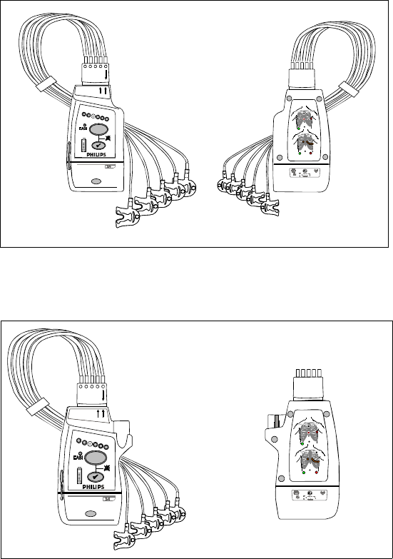
IntelliVue TRx
+
M4841A
IntelliVue TRx
+
M4841A
EASI
FCCID: XXXXXXXX
EASI
IE
A
S
2
3445566
1
back
front
IntelliVue TRx Transceiver - ECG Only
EASI, 3 5,6
IntelliVue TRx
+
M4841A
EASI
FCCID: XXXXXXXX
EASI
IE
A
S
23445566
1
front
IntelliVue TRx+ Transceiver - ECG/SpO2
back

Draft - 1 Aug 08
IntelliVue Telemetry System
1-4 Introducing IntelliVue Telemetry
IntelliVue Telemetry System
The IntelliVue Telemetry System with Smart-Hopping Technology uses cellular
architecture to provide two-way communication between transceivers and the
IntelliVue Information Center. Smart-hopping technology dodges interference
and seeks out the strongest available signal to achieve seamless connections
wherever patients roam on the clinical network. The system connects a number
of individual devices to form a complete method of transporting patient data to a
central repository for subsequent distribution to clinical staff. Full patient
mobility is available within the areas defined by the wireless coverage of the
multiple Access Points.
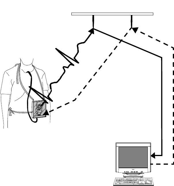
Bi-
directional
Capability
Telemetry transmits the patient’s measurements using radio waves. The signals
obtained from the patient travel from the transceiver to an access point in the
ceiling or wall and then to the Information Center. Bi-directional capability
enables you to remotely control certain transceiver functions from the
Information Center. Physiological data is transported from the transceiver, and a
reverse data channel enables data to be transported to the transceiver. Bi-
directional operations include the following:
• Change SpO2 measurement mode, or turn SpO2 measurement off.
• Enable or disable display of the pleth wave.
• Adjust the transceiver volume, or turn it off.
• Find Device feature for locating a lost transceiver within the coverage
area.
• Suppress SpO2 technical alarms (INOPS) during NBP measurement.
• Return from Standby mode after a patient is away from the unit and not
being monitored by the IntelliVue Telemetry System.
• Configurable Alarm Pause/Suspend time initiated at the transceiver as
well as the Information Center.
• Transceiver location information displayed at the Information Center.
• Transceiver out of area notification at the Information Center.
Draft - 1 Aug 08
IntelliVue Telemetry System
Introducing IntelliVue Telemetry 1-5
Smart-
hopping
Technology
Smart-hoppingTM technology provides dynamic management of the RF
spectrum used by each transceiver. This technology allows a virtually unlimited
number of transceivers to operate simultaneously within the IntelliVue
Telemetry System by creating a frequency-agile system that changes frequency
without user involvement or awareness whenever interference occurs.
Bi-directional Signal Flow in the IntelliVue Telemetry System

Draft - 1 Aug 08
IntelliVue Telemetry System
1-6 Introducing IntelliVue Telemetry
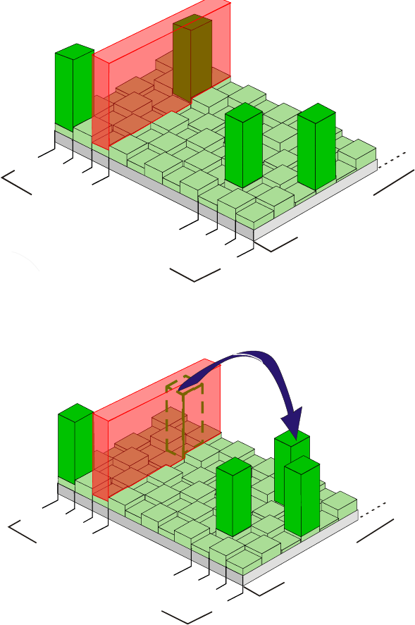
Smart-hopping enables the signal to avoid wireless interference. When baseline
noise is low (see illustrations following), telemetry signals reside in their
frequency/time slot locations. If excessive interference occurs, degrading the
signal, the telemetry signal then “hops” over the interference to a location that
provides optimal signal-to-noise performance.
In cases of excessive intermittent wireless interference, such as machinery
operation or construction activity, you should identify patterns of interference.
This information may assist your service provider in helping you resolve a
problem with interference.
Normal Operation
1395
1400
1427
1432
FREQUENCIES
TIME SLOTS
Desired Signal
Baseline Noise
Interference
Draft - 1 Aug 08
IntelliVue Telemetry System
Introducing IntelliVue Telemetry 1-7
Excessive Interference
’Hop’ to New Frequency/Time Slot
1395
1400
1427
1432
FREQUENCIES
TIME SLOTS
1395
1400
1427
1432
FREQUENCIES
TIME SLOTS

Draft - 1 Aug 08
IntelliVue Clinical Network
1-8 Introducing IntelliVue Telemetry
Spectrum
Sharing The ITS4840A IntelliVue Telemetry System operates in the Wireless Medical
Telemetry Service bands (WMTS - USA only). WMTS uses radio frequency
spectrum which was allocated by the FCC for medical telemetry applications,
with a reduced potential for harmful interference. Although WMTS is managed
by a frequency coordination process, this coordination and licensing does not
grant the user an exclusive right to the spectrum on which their system operates,
and is subject to the terms and conditions of the FCC license. Other WMTS and
non-medical FCC licensees, as well as government agencies, may be legally
authorized to use this licensed spectrum.
The ITS4850A IntelliVue Telemetry System operates in the 2.4 GHz ISM band,
with up to six RF channels using a similar Smart-hopping technology as
described on page 1-5. The system also scans the selected six RF channels to
determine whether the spectrum is sufficiently clear. If the system is too
congested, a system level alert is provided.
IntelliVue Clinical Network
The IntelliVue Clinical Network (ICN) is the communication infrastructure
necessary to tie together all the patient monitoring systems within an
organization. This includes getting information to and from the IntelliVue
Information Center(s).
Patients can be monitored within the defined coverage areas. When a patient
goes out of range, an auditory out-of-range indicator sounds at the transceiver,
and a "No Signal" technical alarm at the Information Center notifies the clinical
staff.
The Network can include both wired and wireless devices. An installation
typically includes the following components:
• IntelliVue Clinical Network infrastructure.
• TRx4841A/TRx4851A Transceivers, bi-directional patient-worn devices.

Draft - 1 Aug 08
Transceiver Use with Other Equipment
Introducing IntelliVue Telemetry 1-9
• ITS4842A/ITS4852A Access Points (AP), placed within the areas with
defined coverage. APs are centers for bidirectional communication
between the transceivers and the Information Center.
• M3150B IntelliVue Information Center for centralized monitoring.
• ITS4843A/ITS4853A Core Access Points (optional) for expanded
coverage.
• M3154A IntelliVue Database Server (optional) for centralized data
management.
• M2636C TeleMon Companion Monitor (optional) for local alarms, NBP
measurement, and bedside display of patient data.
• M8105A MP5, M8102A MP2, and M3002A X2 IntelliVue Patient
Monitors (optional) for bedside display of patient data being sourced from
the transceiver.
Transceiver Use with Other Equipment
IntelliVue
Information
Center
The transceiver’s bi-directional capability enables remote control from the
Information Center for alarm, setup, and general monitoring functions. In
addition, the system supports Telemetry Overview, the pairing of a telemetry
bed with an IntelliVue Patient Monitor for bedside ECG viewing of a single
patient. Telemetry Overview provides the telemetry-monitored waveforms,
numerics, and alarms in an integrated form both on the bedside monitor and at
the IntelliVue Information Center. See “Chapter 10. Pairing Monitoring
Devices” for operating and configuration information.
TeleMon The transceiver can employ the full functionality of the M2636C TeleMon
Companion Monitor, including NBP measurement and local display of alarms.
Connection is made through an interface cable at the Monitor/Service port on
the transceiver. Please refer to “Transceiver Operation when Connected to
TeleMon” on page 9-19 for an operational summary, and the M2636C TeleMon
Instructions for Use for general operating instructions.

Draft - 1 Aug 08
Transceiver Use with Other Equipment
1-10 Introducing IntelliVue Telemetry
Patient
Bedside
Monitors
Remote control of monitoring parameters such as NBP, SpO2, Alarm Suspend,
and Relearn, as well as limited overview of waves and data are supported
through Patient Bedside Monitors equipped with IntelliVue Instrument
Telemetry. Please refer to the Instructions for Use for the specific Patient
Monitor for operating information.
Patient Data can be sourced directly from the transceiver to MP5/MP5T, MP2 or
X2 Patient Monitors. The connection is made through a monitor interface cable
(MP5/MP5T only) or short range radio adapter (SRRA) inserted in the Monitor/
Service port and connected to the monitor. Non-networked MP5/MP5T
monitors can source patient data that includes SpO2, NBP and predictive
temperature measurements to the Information Center. Please refer to the MP5
Instructions for Use for additional information.
M2601B
Transmitters If your hospital uses TRx and/or TRx+ Transceivers and M2601B Transmitters,
you can distinguish between them by:
• Name on the front of the device (TRx or M2601B)
• Label color (light gray for transceivers, dark gray for transmitters)
Draft - 1 Aug 08
Product Safety 2-1
Introduction
2
Product Safety
This chapter consolidates the safety warnings that apply to use of the IntelliVue
Transceivers in a IntelliVue Clinical Network. These warnings are repeated
throughout the book in context where relevant. The chapter includes the
following sections:
• General Safety. . . . . . . . . . . . . . . . . . . . . . . . . . . . . . . . . . . . . . . . . . . . 2-2
• Battery. . . . . . . . . . . . . . . . . . . . . . . . . . . . . . . . . . . . . . . . . . . . . . . . . . 2-5
• ECG . . . . . . . . . . . . . . . . . . . . . . . . . . . . . . . . . . . . . . . . . . . . . . . . . . . 2-6
• ST/AR Arrhythmia . . . . . . . . . . . . . . . . . . . . . . . . . . . . . . . . . . . . . . . . 2-8
• ST/AR ST Segment . . . . . . . . . . . . . . . . . . . . . . . . . . . . . . . . . . . . . . 2-11
•SpO
2 . . . . . . . . . . . . . . . . . . . . . . . . . . . . . . . . . . . . . . . . . . . . . . . . . . 2-12
• Cleaning . . . . . . . . . . . . . . . . . . . . . . . . . . . . . . . . . . . . . . . . . . . . . . . 2-16
• Accessories . . . . . . . . . . . . . . . . . . . . . . . . . . . . . . . . . . . . . . . . . . . . . 2-17

Draft - 1 Aug 08
General Safety
2-2 Product Safety
General Safety
WarningWarning
The IntelliVue Telemetry System should not be used for primary
monitoring in applications where the momentary loss of the ECG is
unacceptable.
WarningWarning
For continued safe use of this equipment, it is necessary that the listed
instructions are followed. Instructions in this manual in no way supersede
established medical procedures.
WarningWarning
Do not touch the patient, or table, or instruments, during defibrillation.
The battery door must be closed during defibrillation. These steps protect
the clinician from high defibrillator voltage.
WarningWarning
This device is not to be used in the vicinity of electrosurgical units because
such use may interrupt or interfere with the transmission of signals from
the transceiver.
WarningWarning
This equipment is not suitable for use in the presence of a flammable
anesthetic mixture with air, or with oxygen or nitrous oxide

Draft - 1 Aug 08
General Safety
Product Safety 2-3
WarningWarning
Do not use patient cables with detachable lead wires that have exposed male
pins. Electrocution could result if these pins are plugged into AC power.
WarningWarning
The system is not completely immune from radio interference although it is
designed to minimize interference through smart hopping. Sources of
interference that may be a problem include failing fluorescent lights and
construction equipment. See “Electromagnetic Compatibility” on page 12-5.
WarningWarning
The product should not be used next to or stacked with other equipment. If
you must stack the product, you must check that normal operation is
possible in the necessary configuration before the product is used on
patients.
WarningWarning
Do not use the transceiver for patient monitoring if it fails the Power On
Self Test.
WarningWarning
When the patient is showering, signal quality and leads off detection may be
compromised due to significant patient movement. Appropriate clinical
precautions must be taken.

Draft - 1 Aug 08
General Safety
2-4 Product Safety
WarningWarning
If the Alarms Suspend indicator on the transceiver remains illuminated
after the button combination to unsuspend alarms is pressed, a transceiver
malfunction may have occurred. (Alarms resume automatically after the
configured alarm suspend duration, or you can resume them manually at
the Information Center.) The transceiver should be replaced, and the
malfunctioning unit should be sent to your service provider.
WarningWarning
If the remote Silence key in the Overview window is enabled for IntelliVue
monitors connected to the Information Center, remote silencing for these
beds may be enabled in other clinical units
WarningWarning
Place the transceiver in a pouch or over clothing, or both, during patient
use. The transceiver should not touch the patient’s skin during use.
WarningWarning
To avoid the risk of strangulation, do not tie a pouch solely around the
patient’s neck.
WarningWarning
Patients should be instructed not to open the battery compartment while
the transceiver is in use.
WarningWarning
Failure on the part of the responsible individual hospital or institution
employing the use of this equipment to implement satisfactory maintenance
as needed may cause undue equipment failure and possible health hazards.

Draft - 1 Aug 08
Battery
Product Safety 2-5
Battery
WarningWarning
The battery door must be closed during defibrillation.
WarningWarning
Use Duracell Alkaline Batteries, size AA, MN 1500, 1.5V, to ensure
specified performance. Outdated, mismatched, or poor-quality batteries
can give unacceptable performance (e.g., insufficient Battery-Low warning
time). The use of fresh high-quality alkaline batteries is strongly
recommended.
WarningWarning
Certain failure conditions, such as short circuits, can cause a battery to
overheat during use. High temperatures can cause burns to the patient and/
or user. If the transceiver becomes hot to the touch, place it aside until it
cools. Then remove the batteries and discard them. Have the transceiver
operation checked by your service provider to identify the cause of
overheating.
WarningWarning
If you receive a BATTERY LOW alarm, the batteries must be promptly
replaced. A “Battery Low” condition that is not corrected will result in a
transceiver shutdown and cessation of monitoring.

Draft - 1 Aug 08
ECG
2-6 Product Safety
WarningWarning
Batteries should be removed from the transceiver at the end of the battery’s
useful life to prevent leakage.
If battery leakage should occur, use caution in removing the battery. The
leaked substance may cause eye or skin irritation. Avoid contact with skin.
Clean the battery compartment according to instructions in “Chapter 11.
Maintenance, Cleaning & Troubleshooting”. Wash hands.
ECG
WarningWarning
Always confirm Information Center observations with clinical observation
of the patient before administering interventions.
WarningWarning
Non-manufacturer supplied accessories and supplies can corrupt the
performance of the equipment. Use only AAMI-EC-12 compliant
electrodes with this device. Use of electrodes that are non-compliant may
provide erroneous results.
WarningWarning
Do not mix and match electrodes of different types. In particular, do not use
electrodes of dissimilar metals. This helps ensure optimal signal quality.

Draft - 1 Aug 08
ECG
Product Safety 2-7
WarningWarning
Every lead must be secured to an electrode on the patient.
Conductive parts of electrodes must not contact earth or other conductive
parts.
Philips recommends that you change the lead label only to reflect the
physical placement of electrodes. This will ensure a match between the
monitored lead and the label, and prevent any possible confusion.
WarningWarning
EASI derived 12-lead ECGs and their measurements are approximations to
conventional 12-lead ECGs. As the 12-lead ECG derived with EASI is not
exactly identical to the 12-lead conventional ECG obtained from an
electrocardiograph, it should not be used for diagnostic interpretations.
EASI lead placement is supported for adult patients only
WarningWarning
When switching between EASI and standard monitoring, there is a loss of
data for 30 seconds.

Draft - 1 Aug 08
ST/AR Arrhythmia
2-8 Product Safety
For Paced
Patients
WarningWarning
The output power of the transceiver and other sources of radio frequency
energy, when used in the proximity of a pacemaker, can be sufficient to
interfere with pacemaker performance. Due to the shielding effects of the
body, internal pacemakers are somewhat less vulnerable than external
pacemakers. However, caution should be exercised when monitoring any
paced patient.
In order to minimize the possibility of interference, position electrodes,
electrode wires, and the transceiver as far away from the pacemaker as
possible.
Consult the pacemaker manufacturer for information on the RF
susceptibility of their products and the use of their products with the
IntelliVue Telemetry System. See the IntelliVue Information Center
Instructions for Use for additional information on monitoring paced
patients.
ST/AR Arrhythmia
WarningWarning
During complete heart block or pacemaker failure (to pace or capture), tall
P-waves (greater than 1/5 of the average R-wave height) can be erroneously
counted by the arrhythmia algorithm, resulting in missed detection of
cardiac arrest.

Draft - 1 Aug 08
ST/AR Arrhythmia
Product Safety 2-9
WarningWarning
Learning
If you initiate learning during ventricular rhythm, the ectopics can be
incorrectly learned as the normal QRS complex. This can result in missed
detection of subsequent events of V-Tach and V-Fib.
WarningWarning
Relearning
Arrhythmia relearning is initiated whenever the transceiver is powered
down for one minute or longer or whenever it is directly connected/
disconnected to an IntelliVue MP5 Patient Monitor. Be sure to check your
patient’s arrhythmia annotation for accuracy whenever relearn has
occurred.
Since Relearn happens automatically, if learning takes place during
ventricular rhythm, the ectopics can be incorrectly learned as the normal
QRS complex. This can result in missed detection of subsequent events of
V-Tach and V-Fib. For this reason, you should:
1. Respond promptly to any technical alarm.
2. Ensure that the arrhythmia algorithm is labeling beats correctly.
When using EASI ECG monitoring, Relearn happens automatically when
there is a LEADS OFF technical alarm. If learning takes place during
ventricular rhythm, the ectopics can be incorrectly learned as the normal
QRS complex. This can result in missed detection of subsequent events of
V-Tach and V-Fib. Be sure to check the beat labels and initiate a relearn to
correct.
1. Respond to the technical alarm [for example, reconnect the electrode(s)].
2. Ensure that the arrhythmia algorithm is labeling beats correctly.

Draft - 1 Aug 08
ST/AR Arrhythmia
2-10 Product Safety
For Paced
Patients
WarningWarning
Some pace pulses can be difficult to reject. When this happens, the pulses
are counted as a QRS complex, and could result in an incorrect HR and
failure to detect cardiac arrest or some arrhythmias. Keep pacemaker
patients under close observation.
WarningWarning
During complete heart block or pacemaker failure (to pace or capture), tall
P-waves (greater than 1/5 of the average R-wave height) can be erroneously
counted by the arrhythmia algorithm, resulting in missed detection of
cardiac arrest.
WarningWarning
For paced patients who exhibit only intrinsic rhythm, the monitor can
erroneously count pace pulses as QRS complexes when the algorithm first
encounters them, resulting in missed detection of cardiac arrest. The risk of
missing cardiac arrest can be reduced by monitoring these patients with the
low heart rate limit at or slightly above the basic/demand pacemaker rate.
A low heart rate alarm alarms you when the patient begins pacing. Proper
detection and classification of the paced rhythm can then be determined.
WarningWarning
When an external pacemaker is being used on a patient, arrhythmia
monitoring is severely compromised due to the high energy level in the
pacer pulse. This can result in the arrhythmia algorithm’s failure to detect
pacemaker non-capture or asystole.

Draft - 1 Aug 08
ST/AR ST Segment
Product Safety 2-11
ST/AR ST Segment
WarningWarning
This device provides ST level change information; the clinical significance
of the ST level change information should be determined by a physician.
ST/AR QT Interval
WarningWarning
The device provides QT and QTc interval change information; the clinical
significance of the QT and QTc interval change information should be
determined by a clinician.

Draft - 1 Aug 08
SpO2
2-12 Product Safety
SpO2
WarningWarning
Always confirm Information Center observations with clinical observation
of the patient before administering interventions.
WarningWarning
Using a sensor during MR imaging can cause severe burns. To minimize
this risk, ensure that the cable is positioned so that no inductive loops are
formed. If the sensor does not appear to be operating properly, remove it
immediately from the patient.
WarningWarning
Do not use disposable sensors on patients who exhibit allergic reactions to
the adhesive.
WarningWarning
Disposable SpO2 sensors can be damaged and lead to patient harm if they
become wet. Wet sensors must be replaced immediately.

Draft - 1 Aug 08
SpO2
Product Safety 2-13
WarningWarning
Prolonged, continuous SpO2 monitoring can increase the risk of changes in
skin characteristics, such as irritation, reddening, blistering or pressure
necrosis, particularly on patients with impaired perfusion and varying or
immature skin morphology. Specific attention must be given to sensor site
inspection for changes in skin quality, proper optical path alignment and
attachment. Check the application site at regular intervals and change the
site if any compromise in skin quality should occur. More frequent
checking can be required due to an individual patient's condition.
WarningWarning
Injected dyes such as methylene blue or intravascular dyshemoglobins such
as methemoglobin and carboxyhemoglobin can lead to inaccurate (over-
estimated) measurements.
WarningWarning
Interference leading to inaccurate measurements can be caused by:
- High levels of ambient light (Hint: cover application site with opaque
material)
- Electromagnetic interference
- Excessive patient movement and vibration.

Draft - 1 Aug 08
SpO2
2-14 Product Safety
WarningWarning
Failure to apply a sensor properly can reduce the accuracy of the SpO2
measurement.
Loose/Tight sensor: If a sensor is too loose, it can compromise the optical
alignment or fall off. If it is too tight, for example because the application
site is too large or becomes too large due to edema, excessive pressure can
be applied. This can result in venous congestion distal from the application
site, leading to interstitial edema, hypoxia and tissue malnutrition. Skin
irritations or ulcerations can occur as a result of the sensor being attached
to one location for too long.
To avoid skin irritations and ulcerations, inspect the sensor application site
every 2-3 hours, and change the application site at least every 4 hours or
according to clinical practice guidelines.
Venous Pulsation: Do not apply sensor too tightly as this results in venous
pulsation and can severely obstruct circulation and lead to inaccurate
measurements.
Ambient Temperature: Never apply an SpO2 sensor at ambient
temperatures above 37 oC (99 oF) because this can cause severe burns after
prolonged application.
Extremities to Avoid: Avoid sites distal to BP cuff or intra-arterial line.
WarningWarning
When the specified Nellcor® sensors are used, the application must be
consistent with the sensor manufacturer's own guidelines.

Draft - 1 Aug 08
SpO2
Product Safety 2-15
WarningWarning
If you measure SpO2 on a limb that has an inflated NBP cuff, a non-
pulsatile SpO2 technical alarm can occur. If the monitor is configured to
suppress this alarm, there can be a delay of up to 60 seconds in indicating
critical patient status, such as sudden pulse loss or hypoxia.
WarningWarning
Removal of the SpO2 sensor during Continuous SpO2 monitoring results in
a "No Sensor" technical alarm. Silencing this technical alarm turns the
SpO2 measurement off. There is no technical alarm for a “No Sensor”
condition in Spot Check mode.
WarningWarning
This equipment is not suitable for use in the presence of a flammable
anesthetic mixture or oxygen concentrations greater than 25% (or partial
pressures greater than 27,5 kPa /206.27 mmHg).

Draft - 1 Aug 08
Cleaning
2-16 Product Safety
Cleaning
WarningWarning
EO is highly explosive, toxic, and a potential occupational carcinogenic and
reproductive hazard. Handle it with extreme care, following U.S.
Occupational Safety and Health Administration (OSHA) standards for EO
(29 CFR 1910.1047)*. Personnel exposure and/or room air must be
monitored per OSHA standards.
Vent sterilizer gas outdoors or to a suitable, evacuated container for
reprocessing, depending upon state, provincial, or country environmental
regulations. Do not vent sterilant indoors.
Vent aerator exhaust only to the outdoors.
* See “References” on page 11-11.
WarningWarning
Comply with OSHA standards*. Do not vent sterilizer gas to the room, but
vent only outdoors or to a suitable, evacuated container, depending upon
state, provincial, or country environmental regulations. (If the mixture is
captured, it can be separated commercially and the component gases re-
used.)
* See “References” on page 11-11.
WarningWarning
To avoid chemical burns and toxic effects, the equipment must be aerated
after sterilization, as described. The aerator must have bacterial filters and
outdoor venting.*
* See “References” on page 11-11

Draft - 1 Aug 08
Accessories
Product Safety 2-17
Accessories
WarningWarning
Use only Philips-approved accessories. Use of product accessories (ECG
leadsets, SpO2 sensors, etc.) other than those specified in this manual may:
- lead to patient injury
- result in increased electromagnetic emissions or decreased immunity of
the product
WarningWarning
Reuse: Never reuse disposable sensors and other accessories that are
intended for single use, or single patient use only.
Packaging: Do not use a sterilized accessory if the packaging is damaged.
WarningWarning
Alignment guides may present a choking hazard. Handle with appropriate
care.
WarningWarning
The SpO2 and Monitor/Service port protective covers may present a
choking hazard. Handle with appropriate care.
Draft - 1 Aug 08
Accessories
2-18 Product Safety
Draft - 1 Aug 08
Transceiver Controls 3-1
Introduction
3
Transceiver Controls
This chapter describes the clinical controls of the transceiver. These controls
include buttons, visual and auditory indicators, ports, and safety labelling
located on the front and back of the device. The chapter includes the following
sections:
• Transceiver Controls - Front. . . . . . . . . . . . . . . . . . . . . . . . . . . . . . . . . 3-2
•Buttons. . . . . . . . . . . . . . . . . . . . . . . . . . . . . . . . . . . . . . . . . . . . . . 3-3
•Power On/Off . . . . . . . . . . . . . . . . . . . . . . . . . . . . . . . . . . . . . . . . 3-4
•Indicators. . . . . . . . . . . . . . . . . . . . . . . . . . . . . . . . . . . . . . . . . . . . 3-4
•Labels . . . . . . . . . . . . . . . . . . . . . . . . . . . . . . . . . . . . . . . . . . . . . . 3-5
•Ports. . . . . . . . . . . . . . . . . . . . . . . . . . . . . . . . . . . . . . . . . . . . . . . . 3-6
• Transceiver Controls - Back. . . . . . . . . . . . . . . . . . . . . . . . . . . . . . . . . 3-7
•Labels . . . . . . . . . . . . . . . . . . . . . . . . . . . . . . . . . . . . . . . . . . . . . . . 3-8
•Safety Symbols & Other Marks . . . . . . . . . . . . . . . . . . . . . . . . . . . 3-8
• Audible Tones. . . . . . . . . . . . . . . . . . . . . . . . . . . . . . . . . . . . . . . . . . . 3-10
•Clinical Use . . . . . . . . . . . . . . . . . . . . . . . . . . . . . . . . . . . . . . . . . 3-11
•Adjustable Sounds . . . . . . . . . . . . . . . . . . . . . . . . . . . . . . . . . . . . 3-12
•Service Sounds . . . . . . . . . . . . . . . . . . . . . . . . . . . . . . . . . . . . . . . 3-13
Note—For the purpose of the following diagrams, the transceiver model shown
is the TRx4851A with SpO2.
Draft - 1 Aug 08
Transceiver Controls - Front
3-2 Transceiver Controls
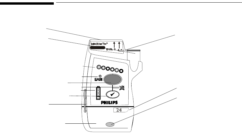
Transceiver Controls - Front
IntelliVue TRx+ Transceiver - Front View
I
3
I
2
I
1
I
4
B
1
B2
O1
L3
P1
P2
P3
L1
L2
The labeled items in the diagram include:
• Buttons (B1-B2)
• Power On/Off (O1)
• Indicators (I1-I4)
• Labels (L1-L3)
• Ports (P1-P3)
TRx4851A
Draft - 1 Aug 08
Transceiver Controls - Front
Transceiver Controls 3-3
Buttons
B1
B2
EASI, 3 5,6
IntelliVue TRx
+
M4841A
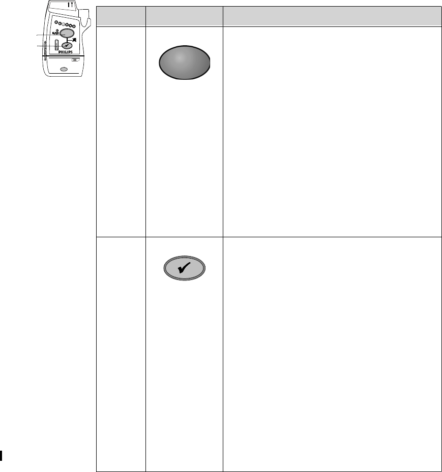
Callout Button Definition
B1 Telemetry Button
• Depending on configuration, directs the
Information Center to generate a Nurse Call
alarm, remote recording, both Nurse Call
alarm and recording, or none. See
“Telemetry Functions at the Information
Center” on page 9-2.
Note—Delayed recordings generated by the
Telemetry button are stored in Alarm
Review at the Information Center.
• When pressed simultaneously with the
Check button, turns Alarm Suspend/Pause
on/off (not when connected to TeleMon or
networked IntelliVue MP5 Patient
Monitor). See “Suspending/Pausing
Alarms” on page 5-2.
B2 Check Button
• Initiates a Status Check of the transceiver.
See “Status Check” on page 4-12.
• Resumes monitoring after Standby. See
“Standby Mode” on page 4-4
• Indicates association with the Information
Center (single beep). See “Audible Tones”
on page 3-10.
• When pressed simultaneously with the
Telemetry button, turns Alarm Suspend/
Pause on/off (if configured and not when
connected to TeleMon or networked
IntelliVue MP5 Patient Monitor). See
“Suspending/Pausing Alarms” on page 5-2.
• Silences the Find Device tone. See
“Locating the Transceiver (Find Device)”
on page 9-3.
• Initiates the Short-Range Radio assignment.
Draft - 1 Aug 08
Transceiver Controls - Front
3-4 Transceiver Controls
Power On/
Off
Indicators
O1
EASI, 3 5,6
IntelliVue TRx
+
M4841A
Callout Battery Door
to Access Definition
O1 Power On/Off Power On/Off
Insertion of batteries turns transceiver power on;
removal of batteries turns power off. See “Turning
the Transceiver On/Off” on page 4-2.
EASI, 3 5,6
IntelliVue TRx
+
M4841A
I 3
I 4
I 2
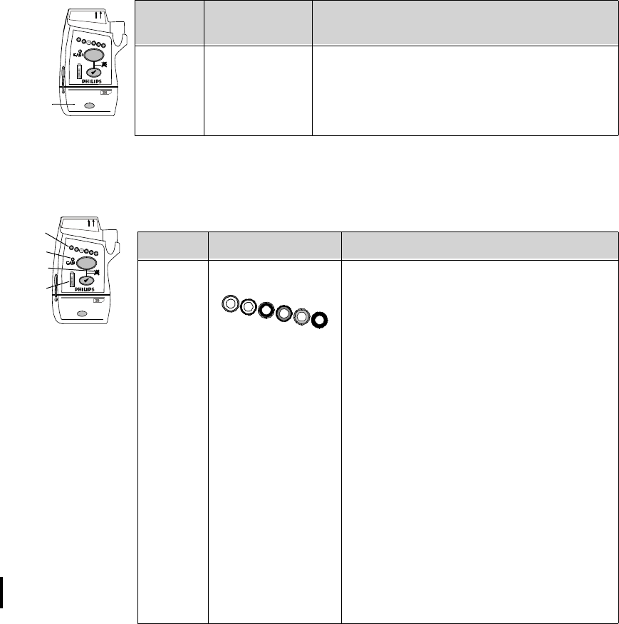
I 1Callout Indicator Definition
I 1Lead Indicator
• Illuminates momentarily during
leadset insertion to indicate attached
leads.
• Illuminates when Check button is
pressed to indicate attached leads.
• During a Leads Off condition,
illuminates to indicate the lead(s) that
need to be reapplied. Reference lead
indicator only on indicates all leads are
off.
• Momentarily illuminates all lead
indicator lights, indicating the
transceiver has no Equipment Label
assigned. Accompanied by “Unlabeled
Device” tone. See “Label Assignment
for Replacement Transceiver” on page
11-2.
• Illuminates after successful Short-
Range Radio assigment.
Draft - 1 Aug 08
Transceiver Controls - Front
Transceiver Controls 3-5
Labels
I 2EASI Indicator
• Illuminates momentarily upon
insertion of leadset in EASI position.
• Illuminates when Check button is
pressed if EASI is in use.
I 3Alarms Suspend/Pause Indicator
Illuminates during alarm pause period
initiated at transceiver, Information Center,
or TeleMon.
I 4Battery Gauge
Illuminates when the Check button is
pressed, indicating the amount of power
remaining in the batteries.
Note—Valid only for recommended battery
type. See “Checking the Battery Power
Level” on page 4-17.
Callout Indicator Definition
EASI
EASI, 3 5,6
IntelliVue TRx
+
M4841A
L1
L2
L3
Callout Label Definition
L1 Leadset Insertion Guide
Assists in aligning the ECG cable for
different leadsets. See “Connecting the ECG
Cable” on page 6-21.
Note—If your unit uses only one monitoring
configuration, the transceiver may have
special alignment guides that allow only one
leadset insertion position.
Warning—Alignment guides may present a
choking hazard. Handle with appropriate
care.
EASI, 3
IntelliVue TRx
5,6
TRx4841A
Draft - 1 Aug 08
Transceiver Controls - Front
3-6 Transceiver Controls
Ports
L2 Device Identification Label
Identifies the device to the IntelliVue
Clinical Network.
L3 Unit Identification Label
Uses one of seven color-coded labels for
visual identification of a clinical unit.
Callout Label Definition
EASI, 3 5,6
IntelliVue TRx
+
M4841A
P1 P2
P3
Callout Definition
P1 ECG Leadset Port
Connection for 3-, 5-, or 6-wire leadset.
P2 SpO2 Sensor Port (IntelliVue TRx+ only)
Connection for SpO2 sensor. See Note.
P3 Monitor/Service Port
Connection for the Short-Range Radio Adapter, the cable to the
TeleMon Companion Monitor and MP5 IntelliVue Patient
Monitor, or to the Service Tool. See Note.
Note—The SpO2 and Monitor/Service ports can be covered with protective
covers when not in use. These are listed in “Appendix A. Accessories”.
Warning—The SpO2 and Monitor/Service port protective covers may present
a choking hazard. Handle with appropriate care.
Draft - 1 Aug 08
Transceiver Controls - Back
Transceiver Controls 3-7
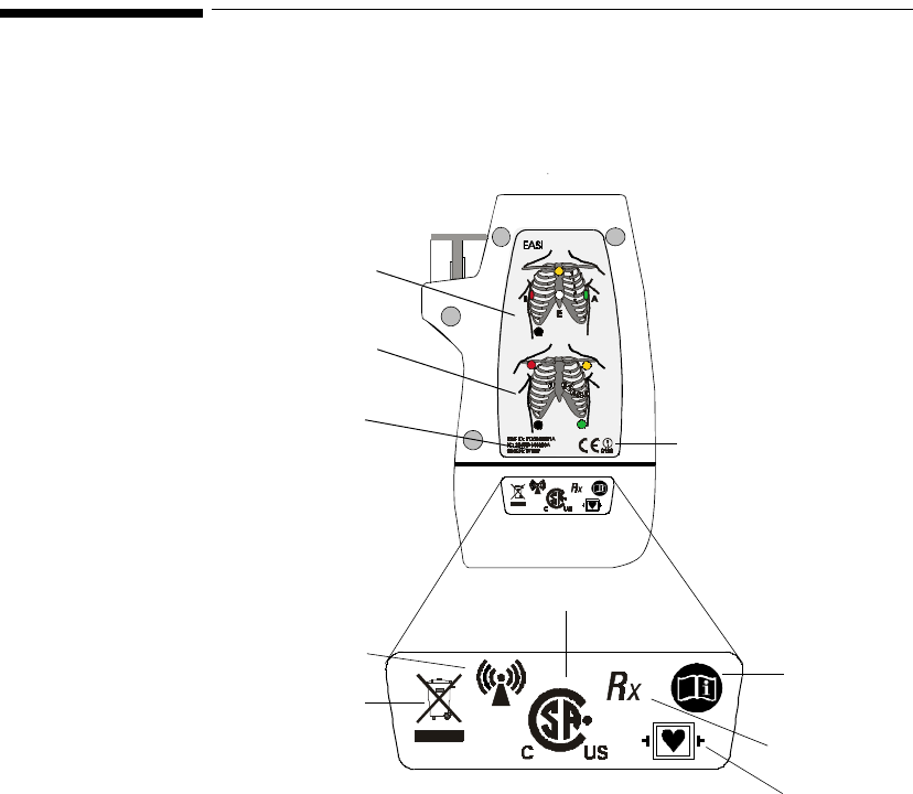
Transceiver Controls - Back
S8-S13 not shown
(inside battery compartment)
IntelliVue TRx+ Transceiver - Back View
EASI
S3
S4 S5
S8
S7
S1
L1
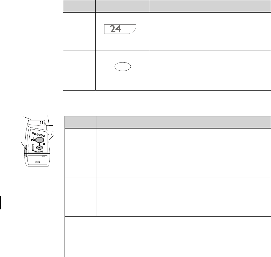
The labeled items in the diagram include:
• Labels (L1-L2)
• Safety symbols and other marks (S1-S14)
L2
EASI
S6
S2
Draft - 1 Aug 08
Transceiver Controls - Back
3-8 Transceiver Controls
Labels
Safety
Symbols &
Other Marks
EASI
EASI
IEA
S
12
3
4
5
6
L1
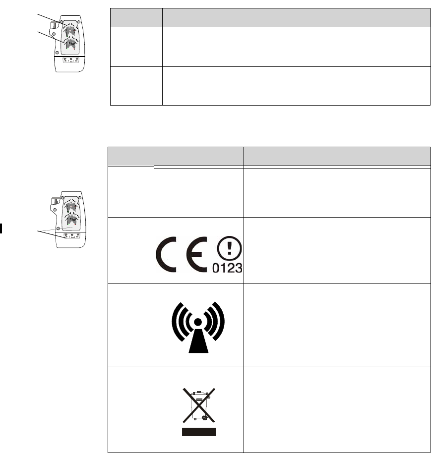
L2 Callout Definition
L1 Electrode Placement Diagram for EASI
See “5-Wire Placement (EASI Mode)” on page 6-16.
L2 Electrode Placement Diagram for Standard ECG
See “5-Wire Placement (Standard Mode)” on page 6-14.
EASI
EASI
IEA
S
12
3
4
5
6
S1-14
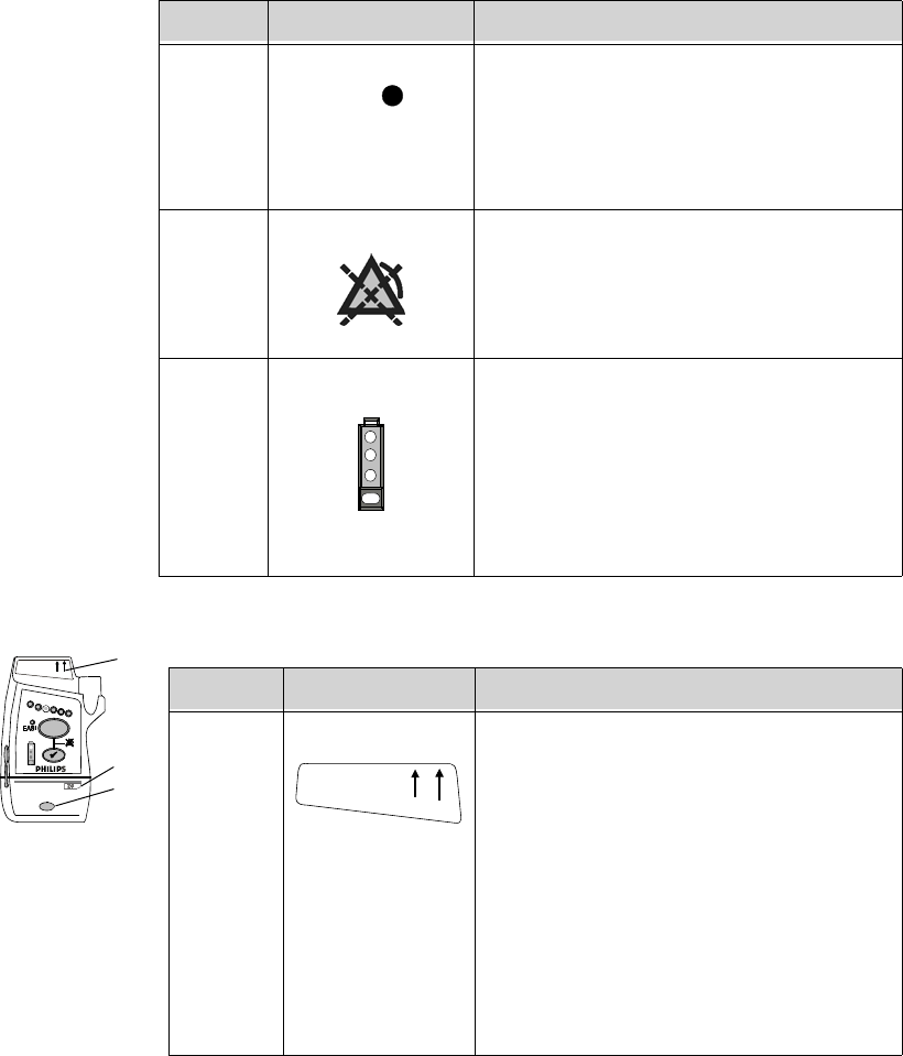
Callout Label Definition
S1 FCC ID: PQCXXXXX
IC: 3549B-XXXX Federal Communications Commission
(FCC) ID
Canadian ID
S2 CE Marking
S3 Non-Ionizing Radiation
Interference to electronic equipment may
occur in the vicinity of devices marked with
this symbol.
S4 Disposal
Dispose of in accordance with the local
country’s requirements.
Draft - 1 Aug 08
Transceiver Controls - Back
Transceiver Controls 3-9
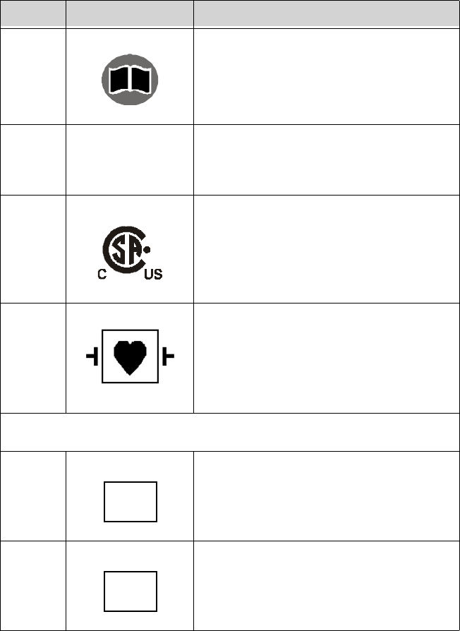
S5 Follow operating instructions.
S6 Prescription Device
S7 Canadian and American standards
compliance
Complies with applicable Canadian and
American standards.
S8 Defibrillation Proof
Patient connections are protected against
defibrillation (DEFIBRILLATION-
PROOF) and are a TYPE CF APPLIED
PART.
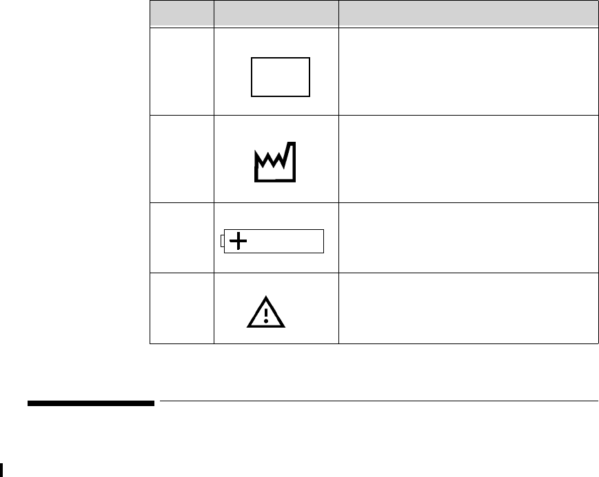
Labels on Inside of Battery Compartment
S9 Catalog Number
Use to identify the equipment during a call
to the Philips Response Center.
S10 Serial Number
Use to identify the equipment during a call
to the Philips Response Center.
Callout Label Definition
i
R
x
REF
SN
Draft - 1 Aug 08
Audible Tones
3-10 Transceiver Controls
Audible Tones
The transceiver produces seven different auditory information signals to inform
you of measurement and transceiver conditions during normal use. Most are
generated automatically.
S11 MAC Address of device
S12 Date of manufacture
S13 Battery Polarity
S14 Attention! See Instructions for Use.
Callout Label Definition
MAC

Draft - 1 Aug 08
Audible Tones
Transceiver Controls 3-11
Clinical Use
Auditory
Information
Signal Sound How Used
Sound 1 beep • Indicates successful Self-Test at power
on.
• Indicates successful SpO2 Spot Check
measurement when measurement is
initiated at the transceiver.
• If the Check button is pressed,
confirms that the transceiver is in
contact with the Information Center
(e.g., when transceiver is brought back
into range).
Sound 2 low-pitch tone Indicates pulse detected during Spot Check
SpO2 measurement.
Note—The pulse tone can be muted from the
Information Center. See “Patient
Configurable Settings in Telemetry Setup” on
page 9-6.
Sound 3 alternating
pitch repeated
tone
Continuous tone to help you locate a missing
transceiver. Initiated by clicking Find
Device in the Telemetry Setup window.
Tone continues until Check button is pressed,
batteries are removed, or batteries completely
discharge.

Draft - 1 Aug 08
Audible Tones
3-12 Transceiver Controls
Adjustable
Sounds Some transceiver sounds can be set to 5 different volume levels (see “Patient
Configurable Settings in Telemetry Setup” on page 9-6). The adjustable sounds
includeSpO2 Spot Check measurement complete/fail, Check/Standby functions,
Sound 4 beep beep • Indicates failed Self-Test at power on.
• Indicates failed SpO2 Spot Check
measurement when measurement is
initiated at the transceiver.
• If it sounds when the Check button is
pressed, it indicates that the transceiver
is not in contact with the Information
Center, or in cases where the
transceiver is not assigned to a sector at
the Information Center but is assigned
to a monitor via short-range radio, the
transceiver is not in contact with the
monitor.
Sound 5 beep beep
every 5 seconds Indicates transceiver is out of range or not
associated with a sector. Sound stops when
contact is re-established with the Information
Center, or it can be silenced by pressing the
Check button for six seconds.
Sound 6 beep every 2
seconds Indicates that the leadset is not inserted
correctly. Accompanied by Invalid Leadset
INOP.
Sound 7 Fast beep beep
and all Leads
Off indicators
briefly flashing
at the same
time
A new assignment has been established
between the transceiver and monitor via
short-range radio connection.
Auditory
Information
Signal Sound How Used

Draft - 1 Aug 08
Audible Tones
Transceiver Controls 3-13
and pulse detection tone. The sounds can be turned off (muted) on a per patient
basis in the Telemetry Setup window.
Service
Sounds Two additional sounds that you may hear occur during the labelling of
transceiver devices within the IntelliVue Clinical Network. The volume of these
sounds is not adjustable, and cannot be turned off. See “Label Assignment for
Replacement Transceiver” on page 11-2.
Auditory
Signal
(sound) Function How Used
Sound 1
(beep) Spot Check Announces a successful SpO2 Spot Check
measurement.
Sound 1
(beep) Check
Button Confirms contact with the Information Center.
Sound 2
(low pitch
tone)
Pulse
Detection
Tone
Indicates pulse during SpO2 Spot Check
measurement.
Service Sound Description
beep beep repeated every
3 seconds, and all visual
indicators flashing
Unlabeled Device.
Equipment Label needs to be assigned at
Information Center. No monitoring.
Fast beep beep and
alternate Leads Off
indicators flashing
Unacknowledged Labeled Device.
Equipment label has been assigned at
Information Center; press the Check button to
complete label assignment. No monitoring.
Draft - 1 Aug 08
Audible Tones
3-14 Transceiver Controls
Draft - 1 Aug 08
Basic Operation 4-1
Introduction
4
Basic Operation
This chapter describes the basic operation of the transceiver. It includes the
following sections:
• Transceiver Safety Information . . . . . . . . . . . . . . . . . . . . . . . . . . . . . . 4-2
• Turning the Transceiver On/Off. . . . . . . . . . . . . . . . . . . . . . . . . . . . . . 4-2
• Briefing the Patient. . . . . . . . . . . . . . . . . . . . . . . . . . . . . . . . . . . . . . . . 4-6
• Testing Transceiver Functionality . . . . . . . . . . . . . . . . . . . . . . . . . . . 4-11
• Battery Information. . . . . . . . . . . . . . . . . . . . . . . . . . . . . . . . . . . . . . . 4-13

Draft - 1 Aug 08
Transceiver Safety Information
4-2 Basic Operation
Transceiver Safety Information
WarningWarning
The system is not completely immune from radio interference although it is
designed to minimize interference through smart hopping. Sources of
interference that may be a problem include failing fluorescent lights and
construction equipment. See “Electromagnetic Compatibility” on page 12-5.
WarningWarning
Place the transceiver in a pouch or over clothing, or both, during patient
use. The transceiver should not touch the patient’s skin during use.
Turning the Transceiver On/Off
WarningWarning
Arrhythmia relearning is initiated whenever the transceiver is powered
down for one minute or longer. Be sure to check your patient’s arrhythmia
annotation for accuracy whenever relearn has occurred.
Draft - 1 Aug 08
Turning the Transceiver On/Off
Basic Operation 4-3
Turning On The transceiver is powered by two AA alkaline batteries. To turn the transceiver
on, insert both batteries. When batteries are inserted:
1. All indicators illuminate briefly.
2. A sequence of sounds indicates the instrument is ready for use.
a. a single beep, indicating that the self test was passed.
b. a series of double beeps, indicating the transceiver is attempting to
establish contact with the Information Center.
c. cessation of sounds, indicating a successful association with the
Information Center.
d. If you hear any other sound sequence, either the device has failed the
automatic Self-Test (in which case you should use a replacement
device), or the device cannot establish contact with the Information
Center (check that a sector has been assigned to the device, and that
the device is within the coverage area).
Turning Off Turn off the transceiver by removing the batteries. A "No Signal" technical
alarm will be in effect at the Information Center until the device is reactivated or
until Standby is initiated.
The configuration data set by the service provider prior to transceiver use is
retained after battery removal.
Sounds at Successful Start-up
Transceiver
connected
with
Information
Center
Transceiver
performs
self-test
One beep
Test passed
Insert batteries Two beeps
every 5 sec-
onds
Beeping stops
Transceiver
searches for
Information
Center

Draft - 1 Aug 08
Turning the Transceiver On/Off
4-4 Basic Operation
RF Auto
Shutoff When RF Auto Shutoff is enabled (default), the transceiver stops broadcasting a
radio signal in order to prevent interference with other transceivers in use. This
condition occurs if there is no ECG signal for 10 minutes and the SpO2 sensor
cable is not inserted in the SpO2 sensor port. The technical alarm, "No Signal",
followed by the "Transmitter Off" INOP will be displayed at the Information
Center. Remove the batteries to conserve battery charge. However, if there is no
ECG signal for 10 minutes but the SpO2 cable is inserted, the transceiver does
not stop broadcasting the signal.
To restart monitoring, insert batteries (if needed), attach leads to the patient,
insert the SpO2 sensor cable in the SpO2 sensor port and press the Check button
to verify association with the Information Center.
Standby
Mode Standby mode is used to temporarily suspend monitoring at the Information
Center, for example, when a patient goes out of access point range or is
discharged.
Standby does not power down the transceiver, so if the standby period is
prolonged, you should remove the batteries.
Initiating
Standby Step Action
1 Do not remove the leads until after the patient is in Standby. This
will avoid an "ECG Leads Off" technical alarm, as well as
reminders, if configured.
2 In the Patient Window, select the Standby button.
3 Select the duration of the standby period (depending on your
system’s configuration: Infinite, 4 Hours, 3 Hours, 2 Hours, 1 Hour,
30 Minutes, 20 Minutes, or 10 Minutes).
Note—If the patient will be discharged, select “Infinite” as the
standby duration.

Draft - 1 Aug 08
Turning the Transceiver On/Off
Basic Operation 4-5
Resuming
Monitoring
4 Select the appropriate location, then select Suspend Monitoring.
The message “Telemetry Standby” and location, if selected, are
displayed in the sector.
Note—If the transceiver is paired with an IntelliVue Patient
Monitor, monitoring will be suspended at both the transceiver and
the IntelliVue Patient Monitor as well as at the Information Center.
The messages "Monitor Standby" and "Telemetry Standby" will be
displayed in the patient sector. If paired directly with an IntelliVue
MP5 Patient Monitor, the message "Monitor Standby" only will be
displayed.
Step Action
Step Action
1 If the standby period has not expired:
•Press the Check button to re-establish contact with the
Information Center. The single beep at the transceiver
verifies that monitoring has resumed.
• If you hear a double beep, click Resume Monitoring at the
Information Center. If there’s still no association, contact the
service provider.
If the standby period has expired:
• Monitoring resumes automatically if the patient is in the
coverage area. Press the Check button to verify the
resumption of monitoring. You should hear a single beep.
If a new patient is connected:
•Press the Check button, or select the Resume Monitoring in
the appropriate patient sector.
Important—When an EASI patient comes out of Standby, the lead
settings are reset to the default EASI leads.

Draft - 1 Aug 08
Briefing the Patient
4-6 Basic Operation
Briefing the Patient
WarningWarning
Patients should be instructed not to open the battery compartment while
the transceiver is in use.
If the Telemetry button has been configured to generate a Nurse Call, recording
at the Information Center, or both, instruct the patient to use the button when
needed.
If desired, you can turn off patient use of the button at the Information Center.
See “Patient Configurable Settings in Telemetry Setup” on page 9-6.
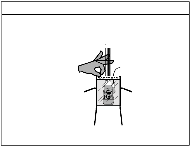
Draft - 1 Aug 08
Briefing the Patient
Basic Operation 4-7
Pouch Use The transceiver is not intended for direct contact with the patient’s skin. During
normal use, the transceiver should be worn over clothing, in a pocket or,
preferably, in a pouch. The carrying pouch with clear front is an appropriate
means for holding the transceiver. See Appendix A, “Accessories” for ordering
information.
Securing
the Pouch Step Action
1 Insert the transceiver into the pouch with lead wires and SpO2
sensor cable, if used, exiting from the top opening of the pouch.
Pinch the velcro enclosures together to close the pouch around the
cables.
Important—Do not coil the cables inside the pouch. They are part of
the wireless system, and need to be freely exposed.
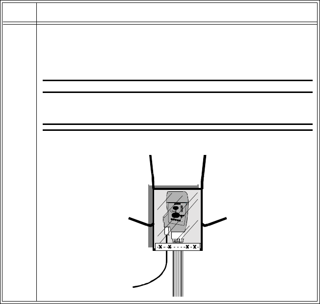
Draft - 1 Aug 08
Briefing the Patient
4-8 Basic Operation
2 Turn the pouch so that the opening is facing downward. This
protects the transceiver from fluid and debris. Secure the pouch on
the patient with the upper ties around the patient’s head and arm and
the lower ties around the patient’s torso.
WarningWarning
To avoid the risk of strangulation, do not tie a pouch solely
around the patient’s neck.
Step Action
Place Tie a under the
arm. Place Tie
b
around the
neck. Tie a and b
together around the neck.
Tie c and d together around
the torso.
cd
ba
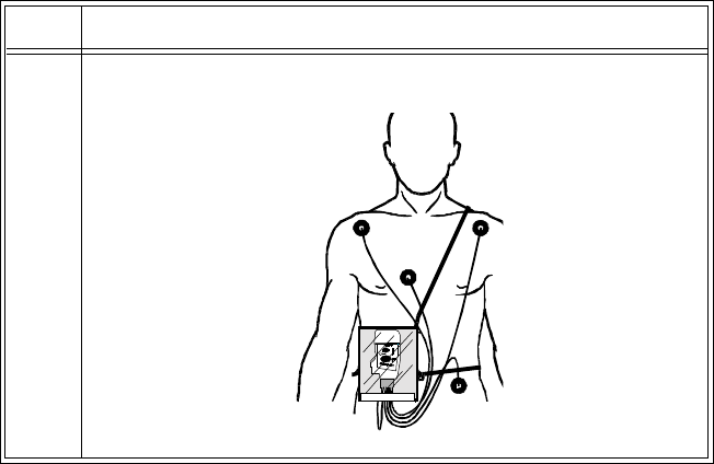
Draft - 1 Aug 08
Briefing the Patient
Basic Operation 4-9
3 Check that the patient is comfortable wearing the pouch with
transceiver.
Step Action

Draft - 1 Aug 08
Briefing the Patient
4-10 Basic Operation
Showering
WarningWarning
When the patient is showering, signal quality and leads off detection may be
compromised due to significant movement. Appropriate clinical
precautions must be taken.
The transceiver can be used to monitor a patient in the shower, but only when
placed inside a Philips carrying pouch and secured on the patient as described
above. The combination of the transceiver and pouch will withstand showering
for up to 10 minutes.
Drying the
Transceiver
after
Showering
After showering, perform the following steps to continue monitoring:
1. Pat dry the leadset connections at the electrodes.
2. Wipe the lead wires with care.
3. If wet, dry the outside of the transceiver with a non-lint producing cloth.
4. If wet, wipe dry the inside of the battery compartment. Dry the batteries.
5. If wet, disconnect the ECG leadset and shake out any water. Dry the
connector pin area with a cotton swab.
6. If wet, allow the SpO2 and Monitor/Service ports to air dry.
Note—The transceiver should not be used for monitoring if the battery
compartment is wet. Remove the batteries and wipe the compartment dry before
continued monitoring use.
Accidental
Wetting If the transceiver is accidentally immersed in liquid for up to 5 minutes, no
damage to the device and no electrical safety issues for the patient will result.
Remove the device, dry it off, and follow the procedure for cleaning/sterilization
under “Cleaning and Sterilization” on page 11-4 as needed.

Draft - 1 Aug 08
Testing Transceiver Functionality
Basic Operation 4-11
Testing Transceiver Functionality
There are two tests of IntelliVue Transceiver functionality:
•Self Test - performed automatically each time the transceiver is turned on.
•Status Check - initiated manually by the clinician.
Self Test
WarningWarning
Do not use the transceiver for patient monitoring if it fails the Power On
Self Test.
Caution
Do not insert a leadset during a self-test. The leadset can be inserted after the
self-test.
A self test of the transceiver functions is automatically performed each time that
the transceiver is turned on (that is, when batteries are inserted). This test should
be performed before ECG leads and/or an SpO2 sensor is attached.
In Case of
Failure If any portion of the self test fails, the transceiver will attempt to report the
failure to the monitoring system. In case of failure, use another transceiver, and
contact your service provider.
Self Test
Status Auditory
Signal Visual Indicators
Passed beep All indicators illuminate for 3 seconds.
Failed beep beep One or more indicators do not light up.

Draft - 1 Aug 08
Testing Transceiver Functionality
4-12 Basic Operation
Status
Check You can check the status of the transceiver indicators at any time.
Initiating a
Status Check Step Action
1Press the
Check button.
The following indicators should illuminate for as long as the Check
button is depressed.
• Battery gauge
• Leads Off indicators
• EASI (if in use)
2 If one or more of the expected indicators do not light up, check the
following:
• Power and position of batteries (see “Checking the Battery
Power Level” on page 4-17).
• Leadset insertion. Make sure the leadset is correctly inserted
in the transceiver and the colored line at the base of the cable
is not visible (see “Connecting the ECG Cable” on page 6-
21).
• Lead positions and connections (see “Verifying Electrode
Connections” on page 6-25).
If there is still a problem, contact your service provider for
assistance.

Draft - 1 Aug 08
Battery Information
Basic Operation 4-13
Battery Information
Battery
Safety
Information WarningWarning
The battery door must be closed during defibrillation.
WarningWarning
Use Duracell Alkalaine batteries, size AA, MN 1500, 1.5V, to ensure
specified performance. Outdated, mismatched, or poor-quality batteries
can give unacceptable performance (e.g., insufficient Battery-Low warning
time). The use of fresh high-quality alkaline batteries is strongly
recommended.
WarningWarning
Certain failure conditions, such as short circuits, can cause a battery to
overheat during use. High temperatures can cause burns to the patient and/
or user. If the transceiver becomes hot to the touch, place it aside until it
cools. Then remove the batteries and discard them. Have the transceiver
operation checked by your service provider to identify the cause of
overheating.
WarningWarning
If you receive a BATTERY LOW alarm, the batteries must be promptly
replaced. A “Battery Low” condition that is not corrected will result in a
transceiver shutdown and cessation of monitoring.

Draft - 1 Aug 08
Battery Information
4-14 Basic Operation
WarningWarning
Batteries should be removed from the transceiver at the end of the battery’s
useful life to prevent leakage.
If battery leakage should occur, use caution in removing the battery. The
leaked substance may cause eye or skin irritation. Avoid contact with skin.
Clean the battery compartment according to instructions in “Chapter 11.
Maintenance, Cleaning & Troubleshooting”. Wash hands.
Inserting/
Removing
Batteries WarningWarning
Arrhythmia relearning is initiated whenever the transceiver is powered
down for one minute or longer. Be sure to check your patient’s arrhythmia
annotation for accuracy whenever relearn has occurred.
Caution
Remove the batteries before storing a transceiver for an extended period of time.
The battery compartment is located at the bottom of the transceiver behind a
swinging door. It accommodates a pair of AA 1.5V Alkaline batteries. Only this
type of disposable battery should be used.
Important—Do not use rechargeable batteries. Use of this type of battery will
adversely affect:
• Battery gauge performance
• Battery low warnings
• Battery life performance
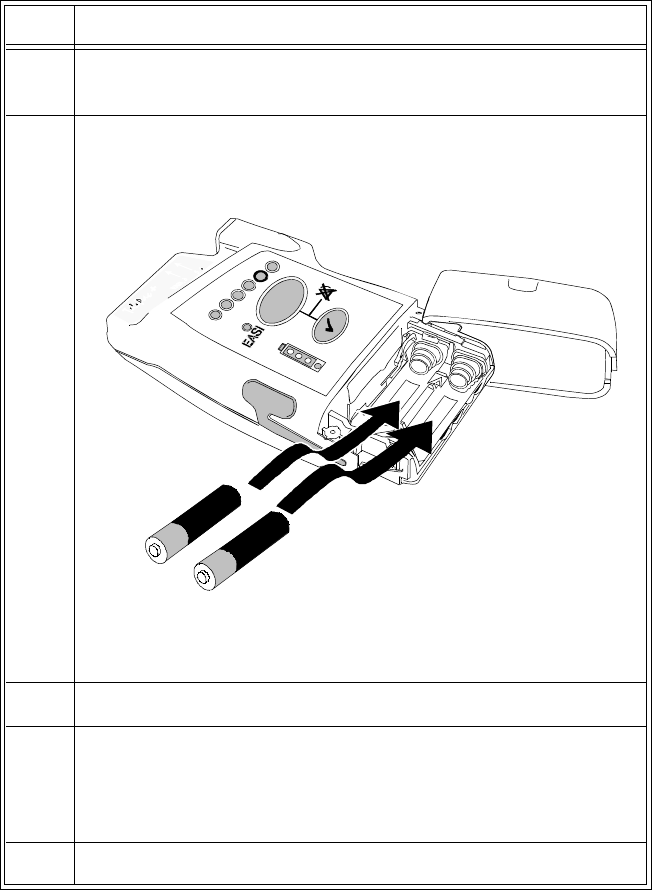
Draft - 1 Aug 08
Battery Information
Basic Operation 4-15
Inserting the
Batteries Insert batteries into the transceiver using the following procedure.
Step Action
1 Open the battery compartment by swinging the compartment door
90o counterclockwise into an open hinged position.
2 Insert two AA 1.5V Alkaline batteries, matching the polarity with
the +/- indications inside the compartment.
Note— Both batteries are inserted with the + polarity in the same
direction.
3 Close the battery compartment door.
4 Listen for the start-up sounds. (See “Turning On” on page 4-3).
Watch for the indicators on the front of the transceiver to illuminate
briefly.
5 Connect the patient cables to the transceiver.
+
+
Draft - 1 Aug 08
Battery Information
4-16 Basic Operation
Removing the
Batteries To remove the batteries, open the battery compartment door and push from the
opening at the back of the compartment to pop the batteries out. Transceiver
settings (ECG leadset type, SpO2 mode, volume, etc.) are retained indefinitely
when the batteries are removed.
If you remove good batteries to turn off the transceiver, keep them together as a
set for later re-use so that both batteries will have the same level of power
remaining.
Batteries should be removed when the transceiver is not in use or is being stored.
Important—DO NOT “STORE” BATTERIES BY LEAVING THEM IN THE
INCORRECT POLARITY POSITION IN THE TRANSCEIVER.
Be careful not to short circuit the batteries. Batteries can get hot when shorted.
Short circuits are caused when a piece of metal touches both the positive and
negative terminals simultaneously. More than a momentary short circuit will
generally reduce the battery life. In case of a short circuit, discard both batteries
in a pair, or just the shorted one if the batteries are new.
Disposal of
Batteries When disposing of batteries, follow local laws for proper disposal. Dispose of
batteries in approved containers. If local regulations require you to recycle
batteries, recycle batteries in accordance with those regulations.

Draft - 1 Aug 08
Battery Information
Basic Operation 4-17
Checking
the Battery
Power Level
When the Check button is pressed, the battery gauge on the transceiver indicates
the battery power level. It is reliable only when specified batteries (i.e., AA 1.5V
Alkaline) are used. The battery gauge is also displayed in the Patient Sector at
the Information Center (if configured) to enable you to closely monitor battery
status, for example, after a change of shift.
To check the power level of the transceiver:
Step Action
1 If connected, disconnect the transceiver from Telemon or MP5.
1Press the Check button to determine the level (see Battery Levels
following).
2If no indicators flash:
1. Check that the batteries are inserted properly.
2. Replace both batteries.
3. If there are still no indicators on the battery gauge, contact
your service provider.
If the indicators illuminate but do not behave as described above,
the transceiver has malfunctioned. Contact your service provider.

Draft - 1 Aug 08
Battery Information
4-18 Basic Operation
Battery Levels
Battery Gauge Approximate
Battery Life*
Remaining
Approximate
Operating
Time*
Remaining
Functionality
4 green indicators > 75% > 34.7 hours Normal operation
3 green indicators > 50% > 23.1 hours Normal operation
2 green indicators > 25% > 11.6 hours Normal operation
1 green indicator 25% to Battery
Low level > 15 minutes Normal operation
1 red indicator Battery Low
level to
Replace
Battery level
< 15 minutes Normal operation
(see note)
no indicator Replace
Battery level
(Check
batteries for
correct
polarity)
none Transceiver
shutdown/RF
shutoff
* Battery life times are based on use of Duracell MN 1500 batteries in a TRx
transceiver. Times for TRx+ are somewhat lower. Life times when other
battery brands are used may be different.
Note—For the TRx+ transceiver, SpO2 functionality is disabled when the red
light (Battery Low) is lit.

Draft - 1 Aug 08
Battery Information
Basic Operation 4-19
Battery Life Battery life is dependent upon:
• Condition of the batteries.
• Parameters being monitored - ECG only, ECG and Spot Check SpO2, or
ECG and Continuous SpO2.
• Use of the Short Range Radio Adapter (SRRA). The transceiver’s
batteries power the SRRA, and under normal operating conditions, battery
life may be reduced by up to 25%. See Cross Ref.
For battery life estimates, see the table on page 12-8.
You can optimize battery life by:
• Removing the batteries when the transceiver is not in use. Keep them
paired for future use.
• Disconnecting the SpO2 adapter cable, if used. When the SpO2 sensor is
disconnected, the SpO2 functionality is automatically powered down, but
if an adapter cable is still connected, it will continue to drain power from
the SpO2 electronics.
Draft - 1 Aug 08
Battery Information
4-20 Basic Operation
Draft - 1 Aug 08
Alarms 5-1
Introduction
5
Alarms
This chapter lists Physiologic (Patient) Alarms and Technical (Inoperative
Condition) Alarms. It also describes how to pause/suspend alarms temporarily.
It includes the following sections:
• Alarm Indicators . . . . . . . . . . . . . . . . . . . . . . . . . . . . . . . . . . . . . . . . . . 5-2
• Suspending/Pausing Alarms. . . . . . . . . . . . . . . . . . . . . . . . . . . . . . . . . 5-2
• Physiologic Alarms. . . . . . . . . . . . . . . . . . . . . . . . . . . . . . . . . . . . . . . . 5-4
• Technical Alarms (INOPs) . . . . . . . . . . . . . . . . . . . . . . . . . . . . . . . . . 5-10

Draft - 1 Aug 08
Alarm Indicators
5-2 Alarms
Alarm Indicators
A description of visual and auditory information signals for patient and technical
alarms on the Information Center is located in the IntelliVue Information Center
Instructions for Use and the Information Center Online Help.The Information
Center documentation also includes the default alarm settings and physiological
alarm limit ranges. Alarm behavior specific to the use of the transceiver paired
with an IntelliVue Patient Monitor is described in “Chapter 10. Pairing
Monitoring Devices”.
Testing
Alarm
Indicators
The visual alarm information signal on the transceiver is the Alarms Suspend
icon. During self test, the Alarm Suspend indicator illuminates briefly, and a
single tone indicates association with the Information Center. These positive test
results indicate that the Alarm Suspend icon on the transceiver is functioning
correctly (see “Self Test” on page 4-11).
Suspending/Pausing Alarms
WarningWarning
If the Alarms Suspend indicator on the transceiver remains illuminated
after the button combination to unsuspend alarms is pressed, a transceiver
malfunction may have occurred. (Alarms resume automatically after the
configured suspend duration time, or you can resume them manually at the
Information Center.) The transceiver should be replaced, and the
malfunctioning unit should be sent to your service provider.
All alarms for a patient can be suspended/paused from the Information Center,
from the TeleMon Companion Monitor, or, depending on transceiver
configuration, from the transceiver itself. The Alarm Suspend/Pause duration is
configurable with a default of two minutes. Alarms automatically resume after
the configured suspend duration time, or can be reactivated manually earlier.

Draft - 1 Aug 08
Suspending/Pausing Alarms
Alarms 5-3
If the transceiver is connected to TeleMon or the MP5 IntelliVue Patient
Monitor, alarms can be suspended only from TeleMon, and not from the
Information Center. The Alarms Suspend icon on the transceiver is lit (see
“Transceiver Controls - Front” on page 3-2), and an "Alarms Suspended"
message appears at TeleMon and the Information Center. Patient monitoring
(display of patient waveforms and numerics) continues for the duration of Alarm
Suspend/Pause.
Step Action
1Press the Telemetry and Check buttons simultaneously to activate
Alarm Suspend/Pause.
While alarms are suspended:
• The transceiver illuminates the Alarms Suspend icon.
• The message "Alarms Suspended" (or "Alarms Paused") is
displayed in the Patient Sector at the Information Center.
Note—For paired bedsides in Telemetry Overview, the
message is "Tele Alarms Suspend".
2 For instructions on how to suspend/pause alarms from the
Information Center, see the IntelliVue Information Center
Instructions for Use and the Information Center Online Help.
For instructions on how to suspend/pause alarms from TeleMon or
the MP5, see their respective Instructions for Use.

Draft - 1 Aug 08
Physiologic Alarms
5-4 Alarms
Unsuspending
& Resuming
Alarms
Alarms will be resumed automatically after the configured suspend duration
time. You can cancel alarm suspend manually before the configured suspend
duration time has expired from the transceiver (see following directions) or from
the Information Center.
Physiologic Alarms
Physiologic alarms indicate a life-threatening situation or a less urgent situation
such as heart rate beyond limits. There are no physiologic alarm signals
generated by the transceiver.
All physiologic alarms are generated at the IntelliVue Information Center,
and all alarm signals must be acknowledged at the Information Center.
Step Action
1Press the Telemetry and Check buttons simultaneously until the
indicator turns off.
• The Alarm Suspend icon is turned off.
• The message "Alarms Suspended" (or "Alarms Paused") is
removed from the Information Center display.
2 Alternately, you can unsuspend alarms at the Information Center.
See IntelliVue Information Center Instructions for Use or Online
Help for directions.
For instructions on how to resume alarms from TeleMon, see the
TeleMon Instructions for Use.

Draft - 1 Aug 08
Physiologic Alarms
Alarms 5-5
WarningWarning
Do not rely exclusively on the audible alarm system for patient monitoring.
Adjustment of alarm volume to a low level during patient monitoring may
result in patient danger. Remember that the most reliable method of patient
monitoring combines close personal surveillance with correct operation of
monitoring equipment.
Arrhythmia alarm chaining and other aspects of alarm behavior, such as alarm
levels, setting alarm limits, customizing arrhythmia alarm settings on a per
patient basis, switching individual measurement alarms on/off, and reviewing
alarm messages, are described in IntelliVue Information Center Instructions for
Use.
There are two levels of arrhythmia analysis available at the Information Center:
Basic and Enhanced. Enhanced analysis includes Basic alarms.
NBP alarms are listed in the TeleMon Instructions for Use and the Information
Center Online Help.
In the following table, Red (***) alarms are listed alphabetically, followed by
the Yellow (**) alarms, and the Yellow (*) arrhythmia alarms.
Physiologic (Patient) Alarms
Alarm Text Priority Condition Source
***ASYSTOLE Red Asystole.
No QRS for 4 consecutive seconds ST/AR
Basic &
Enhanced
Arrhythmia
*** BRADY yyy < xxx Red Extreme Bradycardia.
Heart Rate (yyy) less than Extreme Brady
limit (xxx)
ST/AR
Basic &
Enhanced
Arrhythmia

Draft - 1 Aug 08
Physiologic Alarms
5-6 Alarms
*** DESAT Red Very Low SpO2 Saturation.
SpO2 value below Desaturation limit
Note—Desat limit is set 10 points below
low limit.
SpO2
*** TACHY yyy > xxx Red Extreme Tachycardia.
Heart Rate (yyy) greater than Extreme
Tachy limit
ST/AR
Basic &
Enhanced
Arrhythmia
*** V-FIB/TACH Red Ventricular Fibrillation.
Fibrillatory wave (sinusoidal wave
between 2-10 Hz) for 4 consecutive
seconds
ST/AR
Basic &
Enhanced
Arrhythmia
*** V-TACH Red Ventricular Tachycardia.
Consecutive PVCs greater than or equal to
V-Tach Run limit and Heart Rate greater
than V-Tach limit (xxx)
ST/AR
Basic &
Enhanced
Arrhythmia
** MULTI ST Lx, Ly Yellow Two ST leads (Lx and Ly) exceed alarm
limit elevation or depression for > 60
seconds (EASI mode or when selected).
ST/AR ST
** NURSE CALL Yellow The Telemetry button on the transceiver
has been pressed (and the system is
configured to alarm and the Telemetry
button is on.
Also initiated if the installation includes a
paging system and the Information Center
is configured for paging upon receipt of
Nurse Call signal.
Note—For IntelliVue Information Centers
Release J and later, Nurse Call is a
yellow, one star (*) alarm.
Clinician-
initiated at
transceiver
or by
paging
subsystem
Physiologic (Patient) Alarms
Alarm Text Priority Condition Source

Draft - 1 Aug 08
Physiologic Alarms
Alarms 5-7
** SpO2T yyy > xxx Yellow High SpO2.
SpO2 value (yyy) greater than high SpO2
limit (xxx).
SpO2
** SpO2T yyy < xxxx Yellow Low SpO2.
SpO2 value (yyy) less than low SpO2 limit
(xxx).
SpO2
** ST lead > xxx Yellow STlead is greater than the Elevation limit. ST/AR
** ST lead < xxx Yellow STlead is less than the Depression limit. ST/AR
* HR yyy > xxx Yellow Heart Rate (yyy) greater than the upper
Heart rate limit (xxx). ST/AR
Basic &
Enhanced
Arrhythmia
* HR yyy < xxx Yellow Heart Rate (yyy) lower than the lower
Heart Rate limit (xxx). ST/AR
Basic &
Enhanced
Arrhythmia
* IRREGULAR HR Yellow Consistently irregular rhythm (irregular
R-R intervals). ST/AR
Enhanced
Arrhythmia
* MISSED BEAT Yellow No beat detected for 1.75 x average R-R
interval for Heart Rate greater than 120,
or no beat for 1 second with Heart Rate
greater than 120 (non-paced patient only).
ST/AR
Enhanced
Arrhythmia
* MULTIFORM PVCs Yellow The occurrence of two differently shaped
Vs, each occurring at least twice within
the last 300 beats as well as each
occurring at least once within the last 60
beats.
ST/AR
Enhanced
Arrhythmia
Physiologic (Patient) Alarms
Alarm Text Priority Condition Source

Draft - 1 Aug 08
Physiologic Alarms
5-8 Alarms
* NON-SUSTAIN VT Yellow A run of Vs having a ventricular Heart
Rate greater than V-Tach limit but lasting
for less than the V-Tach Run limit.
ST/AR
Enhanced
Arrhythmia
* PACER NOT CAPT Yellow No QRS for 1.75 x the average R-R
interval with Pace Pulse (paced patient
only).
ST/AR
Basic &
Enhanced
Arrhythmia
* PACER NOT PACE Yellow No QRS and Pace Pulse for 1.75 x the
average R-R interval (paced patient only). ST/AR
Basic &
Enhanced
Arrhythmia
* PAIR PVCs Yellow Two consecutive PVCs between non-
PVCs. ST/AR
Enhanced
Arrhythmia
* PAUSE Yellow No QRS detected for x seconds. Choices
of >1.5 to 2.5 seconds. ST/AR
Enhanced
Arrhythmia
* PVCs >xxx/MIN Yellow PVCs within one minute exceed by the
PVCs/min limit (xxx). ST/AR
Basic &
Enhanced
Arrhythmia
** QTc High Yellow QTc value has exceeded the QTc High
limit for more than 10 minutes ST/AR
Arrhythmia
**dQTc High Yellow dQTc High value has exceeded the dQTc
High Limit for more than 10 minutes. ST/AR
Arrhythmia
Physiologic (Patient) Alarms
Alarm Text Priority Condition Source

Draft - 1 Aug 08
Physiologic Alarms
Alarms 5-9
* R-ON-T PVCs Yellow For Heart Rate less than 100, a PVC with
R-R interval less than 1/3 the average
interval followed by a compensatory
pause of 1.25 x average R-R interval, or 2
such Vs without a compensatory pause
occurring within 5 minutes of each other.
(When Heart Rate is greater than 100, 1/3
R-R interval is too short for detection.)
ST/AR
Enhanced
Arrhythmia
* RUN PVCs Yellow Run of PVCs greater than or equal to 2. ST/AR
Enhanced
Arrhythmia
* SVT Yellow Run of SVPBs greater than or equal to
SVT Run limit and with SVT Heart Rate
greater than the SVT Heart Rate limit.
ST/AR
Enhanced
Arrhythmia
* VENT BIGEMINY Yellow A dominant rhythm of N, V, N, V (where
N= supraventricular beat, V=ventricular
beat).
ST/AR
Enhanced
Arrhythmia
* VENT RHYTHM Yellow A dominant rhythm of adjacent Vs greater
than Vent Rhythm limit and ventricular
Heart Rate less than V-Tach limit.
ST/AR
Enhanced
Arrhythmia
* VENT TRIGEMINY Yellow A dominant rhythm of N, N, V, N, N, V
(where N=supraventricular beat,
V=ventricular beat).
ST/AR
Enhanced
Arrhythmia
Physiologic (Patient) Alarms
Alarm Text Priority Condition Source

Draft - 1 Aug 08
Technical Alarms (INOPs)
5-10 Alarms
Technical Alarms (INOPs)
Technical Alarms, or INOPs (inoperative conditions), are sourced at the
transceiver, the ST/AR algorithm running at the Information Center, or TeleMon
Companion Monitor. They identify inoperative conditions (that is conditions
where the system is not operating properly and therefore cannot measure or
detect alarm conditions reliably). There are four levels of Technical Alarms:
•Severe - Monitoring and alarms disabled. Audible tone at the Information
Center. Must be acknowledged by a clinician.
•Hard - Monitoring and alarms are disabled. Audible tone at the
Information Center.
If the hard INOP is "latched", the sound will be silenced, but the message
will remain on the display until resolution of the offending condition.
•Soft - Monitoring and alarms remain active. No audible tones are
generated.
•Red/Yellow - Replace Battery and ECG Leads Off INOPs may be
configured to display as either Red or Yellow Technical Alarms.

Draft - 1 Aug 08
Technical Alarms (INOPs)
Alarms 5-11
In the following table, technical alarms are listed alphabetically.
Technical Alarms (Inoperative Conditions)
Alarm Text Priority Condition What to do
BATTERY LOW
BATTERY LOW T
Source - Telemetry
Soft Battery power is low. There is less than 15 minutes
of monitoring time
remaining. Replace batteries
promptly to avoid transceiver
shutdown and cessation of
monitoring.
CANNOT ANALYZE
ECG
Source - Information
Center
Hard Arrhythmia algorithm
cannot reliably analyze the
ECG data on any
monitored leads.
Assess the lead selections,
initiate relearn, and validate
analyzed rhythm. Check
other INOPs for possible
source of problem.
CANNOT ANALYZE QT
Source - Information
Center
Soft There have been two
consecutive invalid 5
minute values.
See “Limitations for QT
Monitoring” on page 7-23.
CANNOT ANALYZE ST
Source - Information
Center
Soft ST algorithm cannot
reliably generate any valid
ST values on any
monitored lead.
Review the ECG signal
quality and correct if
necessary. Reposition the
ISO and J points.
Note—If the patient has a
ventricular pacemaker, ST
analysis is not possible.

Draft - 1 Aug 08
Technical Alarms (INOPs)
5-12 Alarms
CENTRAL: TELE ONLY
Source - Patient Monitor
Hard System connectivity via the
transceiver is limited (no
alarms, only local
numerics) when in
companion mode and host
monitor does not have
system connectivity. Only
the transceiver’s
measurements and alarms
can be displayed at the
Information Center.
For more information only.
CHECK ECG SETTINGS
Source - Telemetry
Hard Synchronization of ECG
settings between the
monitor and the
Information Center has
failed.
Check that the ECG settings
in use are appropriate.
Note—When transitioning
between networked and non-
networked monitoring , this
INOP will display. Pressing
the Silence button will
dismiss the INOP.
CHECK ECG SOURCE
Source - Patient Monitor
Yellow
Technical
Alarm
The transceiver and the
monitor both have valid
ECG signals.
Unpair the transceiver and
monitor or remove the
leadset from the device that
is no longer the ECG source.
CHECK PAIRING
Source - Telemetry
Yellow
Technical
Alarm
There is a problem with
device pairing. Check that the bedside
monitor and telemetry device
are correctly paired.
CHECK SpO2T Settings
Source - Telemetry
Hard Synchronization of SpO2T
settings between the
monitor and the
Information Center has
failed.
Check that the SpO2T
settings in use are
appropriate.
Technical Alarms (Inoperative Conditions)
Alarm Text Priority Condition What to do

Draft - 1 Aug 08
Technical Alarms (INOPs)
Alarms 5-13
ECG EQUIP MALF
ECG EQUIP MALF T
Source - Telemetry
Hard Failure of the ECG
equipment or failure to
calibrate ECG.
• Remove leadset.
Remove and re-insert
batteries. Let Self-
Test complete before
reinserting leadset.
• Replace the
transceiver.
• Contact Service.
ECG LEADS OFF
Note—This INOP may also
be configured to display as
a Red or Yellow Technical
Alarm.
Source - Telemetry
Red or
Yellow or
Hard
Technical
Alarm
• Multiple leads are
off.
• The short-range radio
connection between
the transceiver and
the MP5, MP2, or X2
Patient Monitor has
failed.
• Re-attach ECG leads
to patient.
• Identify and remove
the interference source.
• Reduce the number of
devices equipped with
short-range radio
capability.
<electrode> LEAD OFF
Source - Telemetry
Hard Single lead is off.
Note—If primary lead is
MCL, lead will be
identified as V/C in INOP
text.
Re-attach ECG lead to
patient.
INVALID LEADSET
Source - Telemetry
Hard • Wrong leadset.
• Leadset inserted
incorrectly.
• Bad lead selection
switches in the
transceiver.
• Check for appropriate
leadset.
• Check for correct
insertion.
• Contact Service.
LEADSET UNPLUGGED
Source - Telemetry
Hard Leadset has been
unplugged from the
transceiver.
Re-insert the leadset.
Technical Alarms (Inoperative Conditions)
Alarm Text Priority Condition What to do

Draft - 1 Aug 08
Technical Alarms (INOPs)
5-14 Alarms
MORE BED ALARMS
Source - Patient Monitor
Red or
Yellow or
Hard
Technical
Alarm
The monitor is associated
with a transceiver and is
sending data to the
Information Center via the
transceiver. There are
currently more alarms at
the bedside than can be
transmitted to the
Information Center.
For more information only.
Appears at Information
Center only.
NO ARRHYTHMIA
Note—This condition
displays as All ARRH
ALRMS OFF at the IIC.
Source - Information
Center
Soft All basic ST/AR ECG
alarms have been turned
off.
Turn arrhythmia alarms on.
NO ECG AT CENTRAL
Source - Patient Monitor
Hard The ECG measured with
the monitor is not being
sent to the Information
Center via the transceiver.
Check equipment
connections and
configuration settings.
NO ECG SOURCE
Source - Telemetry
Hard The transceiver is paired
with a monitor but the
Information Center is not
detecting a valid ECG
signal from either of them.
Check equipment
connections and
configuration settings.
Technical Alarms (Inoperative Conditions)
Alarm Text Priority Condition What to do

Draft - 1 Aug 08
Technical Alarms (INOPs)
Alarms 5-15
NO SIGNAL
Source - Information
Center
Hard • Transceiver is
outside the coverage
area, or
• No batteries in
transceiver, or
• Transceiver has
failed, or
• Connection to
Database Server has
failed.
• Short-range radio
connection has
failed.
• Make sure that the
transceiver is within
the coverage area and
has good batteries.
• Replace the transceiver
if Power On Self Test
fails.
• Put bed in Standby.
• Contact Service.
OUT OF AREA
Source - Information
Center
Hard The transceiver is
communicating with an
access point designated as a
boundary limit.
For more information only.
REPLACE BATTERY
REPLACE BATTERY T
Note—This INOP may also
be configured to display as
a Red or Yellow Technical
Alarm.
Source - Telemetry
Red or
Yellow or
Hard
Technical
Alarm,
Latched
Dead battery. No
monitoring is occurring. Replace batteries.
SOME ECG ALRMS OFF
Source - Information
Center
Soft Some yellow arrhythmia
alarms have been turned off
for this patient.
For information only.
Technical Alarms (Inoperative Conditions)
Alarm Text Priority Condition What to do

Draft - 1 Aug 08
Technical Alarms (INOPs)
5-16 Alarms
SpO2T EQUIP MALF
Source - Telemetry
Hard Malfunction in the SpO2
equipment Contact Service.
SpO2T ERRATIC
Source - Telemetry
Hard Erratic SpO2
measurements, often due to
a faulty sensor or invalid
SpO2 measurements, or
incorrect transducer
position
Repeat measurement,
reposition sensor on patient,
or finally, replace sensor.
SpO2T EXTD UPDATE
Numeric is replaced by a
-?-.
Source - Telemetry
Soft The update period of
displayed values is
extended due to an NBP
measurement on the same
limb or an excessively
noisy signal.
If NBP is not active, check
the sensor placement.
Reposition the sensor on
patient, or replace sensor.
SpO2T INTERFERENCE
Source - Telemetry
Hard Level of ambient light or
level of electrical
interference are so high that
the SpO2 sensor cannot
measure SpO2 and pulse
rate.
Reduce ambient light to
sensor or electrical noise
sources.
SpO2T LOW PERFUSION
Source - Telemetry
Soft Accuracy may be reduced
due to low perfusion. Data
displayed with ?.
Increase perfusion. Change
sensor site. Avoid site distal
to BP cuff or intra-arterial
line. Warm the site.
SpO2T NO SENSOR
Note—Silencing this
technical alarm turns off
the SpO2 measurement.
Source - Telemetry
Hard No sensor attached to SpO2
device Attach SpO2 sensor.
Technical Alarms (Inoperative Conditions)
Alarm Text Priority Condition What to do

Draft - 1 Aug 08
Technical Alarms (INOPs)
Alarms 5-17
SpO2T NOISY SIGNAL
Source - Telemetry
Hard Excessive patient
movements or electrical
interference are causing
irregular pulse patterns
Reduce movement or
electrical noise sources.
SpO2T NON-PULSATILE
Note—When paired
directly with an IntelliVue
MP5 Patient Monitor, the
INOP will display as
SpO2T SENSOR OFF.
Source - Telemetry
Hard Pulse is too weak or not
detectable Check connection to patient.
Change sensor site. Avoid
site distal to BP cuff or intra-
arterial line.
SpO2T SENSOR MALF
Source - Telemetry
Hard Malfunction of the SpO2
sensor/adapter cable Replace sensor.
SRR INTERFERENCE
Source - Patient Monitor
Hard The short-range radio
connection has interference
from another device.
Move transceiver away from
other interference sources. If
INOP persists, contact
Service.
SRR INVALID CHAN
Source - Patient Monitor
Hard The channel configuration
of the short-range radio is
invalid.
Check channel and channel
mask configuration.
Contact Service.
SRR MALFUNCTION
Source - Patient Monitor
Hard There is a malfunction in
the short-range radio
device.
If the INOP persists, contact
Service.
TAAP DISABLED
Source - Patient Monitor
Hard The monitor’s telemetry
configuration does not
allow connection of the
transceiver to the monitor.
Check configuration settings
at the monitor.
Contact Service.
Technical Alarms (Inoperative Conditions)
Alarm Text Priority Condition What to do

Draft - 1 Aug 08
Technical Alarms (INOPs)
5-18 Alarms
TELE CONFIG
UNSUPPORTED
Source - Patient Monitor
Hard Transceiver not supported
(companion mode). Make sure the transceiver is
the correct revision.
Contact Service.
TELE DISCONNECTED
Sourece - Telemetry
Red,
Yellow or
Hard
Technical
Alarm
• The interface cable is
not connected.
• Short-range radio
connection between
the transceiver and
the patient monitor
has been lost.
If the disconnection is not
intentional:
• Re-connect the
interface cable.
• Identify and remove
interference sources
such as bluetooth
devices, DECT
phones, microwaves,
etc.
• Reduce the number of
devices equipped with
short-range radio
capability.
TELE INCOMPATIBLE
Source - Patient Monitor
Hard Transceivers equipped with
SRRA are not supported
with this revision of the
Information Center.
Check equipment
configuration/compatibility.
Contact Service.
TELEMETRY STANDBY Soft Information Center standby
mode timer is active, or
patient was not returned to
telemetry coverage area.
There is no data from bed.
Cancelled when patient is
removed from Standby.
Technical Alarms (Inoperative Conditions)
Alarm Text Priority Condition What to do

Draft - 1 Aug 08
Technical Alarms (INOPs)
Alarms 5-19
TELE SYNC UNSUPP
Source - Telemetry
Hard Incompatible MMS The MMS in use does not
support synchronization of
ECG and SpO2 settings
between the monitor and
Information Center after a
transceiver has been paired.
The MMS must be revision
E.00 or above.
TELE UNSUPPORTED
Source - Patient Monitor
Hard The transceiver is not
supported for direct
connection to the monitor.
Make sure the transceiver is
the correct revision.
TELE WEAK SIGNAL
Source - Telemetry
Soft • Patient is at outer
range of the radio
coverage area.
• Telemetry pack is
receiving a weak
signal with high data
loss from the AP.
• Condition exists for
multiple devices in a
specific area
• Return patient to the
coverage area.
• If patient is in close
proximity to AP,
replace telemetry pack.
Contact service.
• The AP covering the
specific area is
suspect. Contact
Service.
TRANSMITTER MALF
Source - Telemetry
Hard Transceiver malfunction Replace and contact Service.
TRANSMITTER OFF
Source - Telemetry
Hard RF Auto Shutoff after 10
minutes of all leads off and
no SpO2 sensor connected.
• Reattach ECG leads to
patient.
• Reattach SpO2 sensor.
• Press the Check
button.
Technical Alarms (Inoperative Conditions)
Alarm Text Priority Condition What to do
Draft - 1 Aug 08
Technical Alarms (INOPs)
5-20 Alarms
Draft - 1 Aug 08
ECG Monitoring 6-1
Introduction
6
ECG Monitoring
This chapter covers the specifics of ECG measurement. It includes the
following sections:
• ECG Safety Information. . . . . . . . . . . . . . . . . . . . . . . . . . . . . . . . . . . . 6-2
• Measuring ECG . . . . . . . . . . . . . . . . . . . . . . . . . . . . . . . . . . . . . . . . . . 6-4
• Positioning ECG Electrodes . . . . . . . . . . . . . . . . . . . . . . . . . . . . . . . . 6-10
• Connecting the ECG Cable. . . . . . . . . . . . . . . . . . . . . . . . . . . . . . . . . 6-21
• Verifying Electrode Connections . . . . . . . . . . . . . . . . . . . . . . . . . . . . 6-25
• Monitoring during Leads Off . . . . . . . . . . . . . . . . . . . . . . . . . . . . . . . 6-27
• Optimizing ECG Measurement Performance. . . . . . . . . . . . . . . . . . . 6-29

Draft - 1 Aug 08
ECG Safety Information
6-2 ECG Monitoring
ECG Safety Information
WarningWarning
Always confirm Information Center observations with clinical observation
of the patient before administering interventions.
WarningWarning
Every lead must be secured to an electrode on the patient.
Conductive parts of electrodes must not contact earth or other conductive
parts.
Philips recommends that you change the lead label only to reflect the
physical placement of electrodes. This will ensure a match between the
monitored lead and the label, and prevent any possible confusion.
WarningWarning
When switching from EASI to standard monitoring, there is a loss of data
for 30 seconds.
WarningWarning
EASI derived 12-lead ECGs and their measurements are approximations
to conventional 12-lead ECGs. As the 12-lead ECG derived with EASI is
not exactly identical to the 12-lead conventional ECG obtained from an
electrocardiograph, it should not be used for diagnostic interpretations.
EASI lead placement is supported for adult patients only

Draft - 1 Aug 08
ECG Safety Information
ECG Monitoring 6-3
For Paced
Patients
WarningWarning
The output power of the transceiver and other sources of radio frequency
energy, when used in the proximity of a pacemaker, can be sufficient to
interfere with pacemaker performance. Due to the shielding effects of the
body, internal pacemakers are somewhat less vulnerable than external
pacemakers. However, caution should be exercised when monitoring any
paced patient.
In order to minimize the possibility of interference, position electrodes,
electrode wires, and the transceiver as far away from the pacemaker as
possible.
Consult the pacemaker manufacturer for information on the RF
susceptibility of their products and the use of their products with the
IntelliVue Telemetry System. See the IntelliVue Information Center
Instructions for Use for additional information on monitoring paced
patients.
Caution
During defibrillation, monitoring may be temporarily interrupted or distorted. It
may take several seconds for the ECG trace to reappear on the screen. After
defibrillation, the device will continue to monitor as before; the device settings
will not be affected.

Draft - 1 Aug 08
Measuring ECG
6-4 ECG Monitoring
Measuring ECG
The electrocardiogram (ECG) measures the electrical activity of the heart and
displays it on the Information Center as a waveform and a numeric.
In order to compare measured ECG signals, the electrodes (or leadsets) are
placed in standardized positions, forming so-called “leads”. To obtain ECG
signals optimized for use in diagnosis and patient management in different care
environments, different leadsets in varying lead placements are used. Both
standard lead and EASI lead placements can be used with the transceiver.
ECG
Configuration The IntelliVue Transceiver supports 3-, 5-, and 6-wire leadsets. The 5-wire
leadset can be used for either standard or EASI electrode configurations.
The transceiver leadset configuration choices are as follows:
• Leadset Mode = ALL (default)
This configuration allows you to switch the leadset type and position during
use. The transceiver will automatically reconfigure itself accordingly.
• Leadset Mode = EASI ONLY
In this configuration only the use of the 5-wire leadset in the EASI position is
allowed.
• Leadset Mode = NO EASI
In this configuration the use of 3- and 6-wire leadsets is allowed along with the
use of the 5-wire leadset in the standard position only.
• Leadset Mode = 3 WIRE ONLY
In this configuration, only the use of the 3-wire leadset is allowed.

Draft - 1 Aug 08
Measuring ECG
ECG Monitoring 6-5
The transceiver detects the inserted leadset type and automatically determines
the ECG measurement and transmitted leads. The Leadset Insertion Guide on
the device will assist you in ensuring the correct measurement during transceiver
usage. If the transceiver senses the insertion of a leadset not matching the
current configuration, the transceiver will source the ECG per the leadset
detected and issue and auditory signal to indicate the condition. An INVALID
LEADSET INOP is generated at the Information Center.
Note—The labels and colors of the ECG electrodes differ according to the
standards that apply for your hospital. The electrode placement references and
illustrations in this chapter use the AAMI labels and colors. See the table below
for additional label and color information.
Electrode Labels Electrode Colors
AAMI EASI IEC AAMI IEC
RA I R White Red
LA S L Black Yellow
LL A F Red Green
RL N N Green Black
V/Va E C/Ca Brown White
Vb Cb Brown/White White/Red
V2 C2 Brown/Yellow White/Yellow
V3 C3 Brown/Green White/Green
V4 C4 Brown/Blue White/Brown
V5 C5 Brown/Orange White/Black
V6 C6 Brown/Violet White/Violet

Draft - 1 Aug 08
Measuring ECG
6-6 ECG Monitoring
There is no cardiotach within the transceiver; cardiotach analysis resides in the
arrhythmia algorithm at the Information Center. Therefore, arrhythmia analysis
is always turned on for telemetry patients. Arrhythmia analysis is either Basic or
Enhanced, depending on the product configuration.
ECG Leads
Monitored Depending on the leadset connected to the transceiver, a different set of
viewable leads are available at the Information Center. The transceiver can
source up to four raw ECG waves.
If you are using ... these leads can be selected at the
Information Center
3-wire I, II, III
Sourced (raw) waves are received as:
• Channel 1 = I, II, or III
Default is II.
5-wire (Standard mode) I, II, III, aVR, aVL, aVF, MCL and V
Sourced (raw) waves are received as:
• Channel 1 = II
• Channel 2 = III
• Channel 3 = MCL
Defaults are II, V, III.

Draft - 1 Aug 08
Measuring ECG
ECG Monitoring 6-7
5-wire (EASI mode) I, II, III, aVR, aVL, aVF, V1, V2, V3, V4, V5,
V6
In EASI mode, the sourced (raw) waves are
received as:
• Channel 1 = Vector 1 (A-I)
• Channel 2 = Vector 2 (A-S)
• Channel 3 = Vector 3 (E-S)
Defaults are II, V2, III, V5.
Note—Arrhythmia monitoring is performed only
on the primary and secondary leads selected at
the Information Center, although you can view
and perform ST analysis on all 12 EASI derived
leads.
If you are using ... these leads can be selected at the
Information Center

Draft - 1 Aug 08
Measuring ECG
6-8 ECG Monitoring
6-wire
(Vb is not supported on
TeleMon and is only
supported on MP5 Patient
Monitors with 12-Lead
option)
I, II, III, aVR, aVL, aVF, V1, V2, V3, V4, V5,
V6, V7, V8, V9, V3R, V4R, V5R.
Sourced (raw) waves are received as:
• Channel 1 = II
• Channel 2 = III
• Channel 3 = Va
• Channel 4 = Vb
Defaults are II, Va = V2, III,Vb = V5.
The two chest leads, Va and Vb, can be placed
on the patient in any of the V lead positions (V1
through V9, V3R, V4R, V5R). Lead assignment
is available at the Information Center. When
unassigned, the chest leads use the defaults.
Note—The lead label assigned to Vb cannot be
selected for Va even though Vb does not appear
to be used.
Note—When display of the pleth wave is
enabled at the Information Center, the second
chest lead (Vb) is not available for monitoring.
If you are using ... these leads can be selected at the
Information Center

Draft - 1 Aug 08
Measuring ECG
ECG Monitoring 6-9
Reconstructed
Leads Reconstruction of leads from the sourced wave is defined by the calculations in
the following table. EASI reconstructed leads are a linear combination of all
three raw EASI leads.
ECG Lead
Clinical Calculations
in terms of electrodes
3-Wire 5-Wire
Standard 6-Wire
II ILA-RA
II
(default) II
(default) II
(default) LL-RA
III III
(default) III
(default) LL-LA
-MCL V-LA, where V=C
-aVR aVR RA-(LA+LL)/2
-aVL aVL LA-(RA+LL)/2
-aVF aVF LL-(LA+RA)/2
-V
(default) V-(RA+LA+LL)/3, where V=C
Va Va-(RA+LA+LL)/3, where
Va=V2 (default) position
Vb Vb-(RA+LA+LL)/3, where Vb
=V5 (default) position

Draft - 1 Aug 08
Positioning ECG Electrodes
6-10 ECG Monitoring
Positioning ECG Electrodes
WarningWarning
Do not mix and match electrodes of different types. In particular, do not
use electrodes of dissimilar metals. This helps ensure optimal signal
quality.
WarningWarning
Non-manufacturer supplied accessories and supplies can corrupt the
performance of the equipment. Use only AAMI EC-12 compliant electrodes
with this device. Use of electrodes that are non-compliant may provide
erroneous results.
Caution
To protect the transceiver from damage during defibrillation, to ensure accurate
ECG information, and to provide protection against signal noise and other
interference, use only ECG electrodes and cables specified by Philips.
Correct lead placement is always important for accurate diagnosis. Especially in
the precordial leads, which are close the heart, QRS morphology can be greatly
altered if an electrode is moved away from its correct location. Each electrode is
color-coded. Use the diagrams for 5-lead standard and EASI placement on the
back of the transceiver and in this section for guidance. Additional lead
placement information is available in the Online Help at the IntelliVue
Information Center.
When placing electrodes on the patient, choose a flat, non-muscular site where
the signal will not be impacted by either movement or bones.
Philips recommends that electrodes be changed every 24 hours.

Draft - 1 Aug 08
Positioning ECG Electrodes
ECG Monitoring 6-11
In addition to correct positioning of the electrodes, optimal skin preparation
prior to electrode placement will help ensure a clear signal for diagnosis.
Step Action
1 Prepare the patient’s skin. Good electrode-to-skin contact is
important for a good ECG signal, as the skin is a poor conductor of
electricity.
• Select sites with intact skin, without impairment of any kind.
• Clip or shave hair from the site as necessary.
• Wash site with soap and water, leaving no soap residue.
Note--Philips does not recommend using ether or pure
alcohol, because they dry the skin and increase the resistance.
• Dry thoroughly.
• Use ECG skin preparation paper (abrasive) to remove dead
skin cells and to improve the conductivity of the electrode
site.
2 Check electrodes for moist gel, and attach to the clips. If you are not
using pre-gelled electrodes, apply electrode gel to the electrodes
before placement.
Note—Gel must be moist to provide a good signal.
3 Place the electrodes on the patient according to the lead placement
you have chosen (see the electrode placement diagrams following).
Place the edge down, then “roll down” the rest of the pad. Press
firmly around the adhesive edge toward the center.
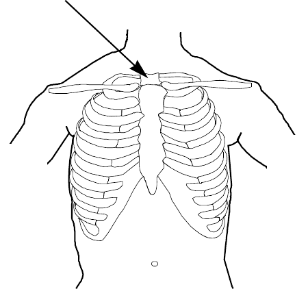
Draft - 1 Aug 08
Positioning ECG Electrodes
6-12 ECG Monitoring
Locating the
Fourth
Intercostal
Space
For accurate chest electrode placement and measurement, it is important to
locate the fourth intercostal space. This can be done using the Angle of Lewis.
1. Locate the second intercostal space by first palpating the Angle of Lewis
(the bony protuberance where the body of the sternum joins the
manubrium). This rise in the sternum is where the second rib is attached,
and the space just below this is the second intercostal space.
2. Palpate and count down the chest until you locate the fourth intercostal
space.
Angle of Lewis
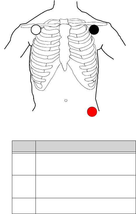
Draft - 1 Aug 08
Positioning ECG Electrodes
ECG Monitoring 6-13
3-Wire
Placement
Lead Placement
RA directly below the clavicle and near the
right shoulder
LA directly below the clavicle and near the
left shoulder
LL on the left lower abdomen
RA LA
LL

Draft - 1 Aug 08
Positioning ECG Electrodes
6-14 ECG Monitoring
5-Wire
Placement
(Standard
Mode)
Lead Placement
RA directly below the clavicle and near the
right shoulder
LA directly below the clavicle and near the
left shoulder
LL on the left lower abdomen
RL on the right lower abdomen
V on the chest, the position depends on your
required lead selection. The typical
position is V1, although this may vary
according based on your hospital’s
protocol.
V2V3 V4 V5 V6
V1
RA LA
RL LL

Draft - 1 Aug 08
Positioning ECG Electrodes
ECG Monitoring 6-15
V1 on the fourth intercostal space at the right
sternal border
V2 on the fourth intercostal space at the left
sternal border
V3 midway between the V2 and V4 electrode
positions
V4 on the fifth intercostal space at the left
midclavicular line
V5 on the left anterior axillary line, horizontal
with the V4 electrode position
V6 on the left midaxillary line, horizontal
with the V4 electrode position
Lead Placement
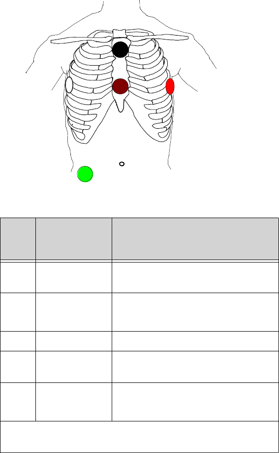
Draft - 1 Aug 08
Positioning ECG Electrodes
6-16 ECG Monitoring
5-Wire
Placement
(EASI Mode)
Lead Corresponds
to Standard
Lead Placement
E V on the lower sternum at the level of the
fifth intercostal space
A LL on the left midaxillary line at the same
level as the E electrode
S LA on the upper sternum
I RA on the right midaxillary line at the
same level as the E electrode
N Reference can be anywhere, usually below the
sixth rib on the right hip
Note—Make sure that the S and E electrodes line up vertically on
the sternum, and that the I, E and A electrodes align horizontally.
E
S
AI
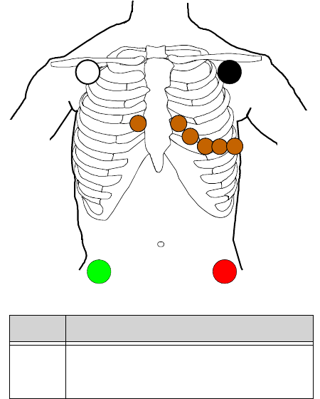
Draft - 1 Aug 08
Positioning ECG Electrodes
ECG Monitoring 6-17
6-Wire
Placement 6-lead placement uses the same four limb leads as 5-lead standard placement,
and two precordial leads - referred to at the Information Center as Va and Vb.
The default position of Va - the brown lead - is at the V2 position.
The default position for Vb - the brown/white lead - is at the V5 position.
The lead placement for the Va and Vb lead labels must be appropriate. If your
unit uses other precordial leads for Va and Vb, they may be assigned in Unit
Settings as defaults for your whole unit, or you may need to assign the new
positions on a per-patient basis in the Patient Window at the Information Center
(see “Telemetry Controls in the Patient Window” on page 9-2).
Lead Placement
RA directly below the clavicle and near the
right shoulder
V2V3 V4 V5 V6
V1
RA LA
RL LL

Draft - 1 Aug 08
Positioning ECG Electrodes
6-18 ECG Monitoring
LA directly below the clavicle and near the
left shoulder
RL on the right lower abdomen
LL on the left lower abdomen
Va on the chest, the position depends on
your required lead selection (see
below). The default position is V2. For
other positions, relabel the lead at the
Information Center.
Vb on the chest, the position depends on
your required lead selection (see
below). The default position is V5. For
other positions, relabel the lead at the
Information Center.
Lead Placement
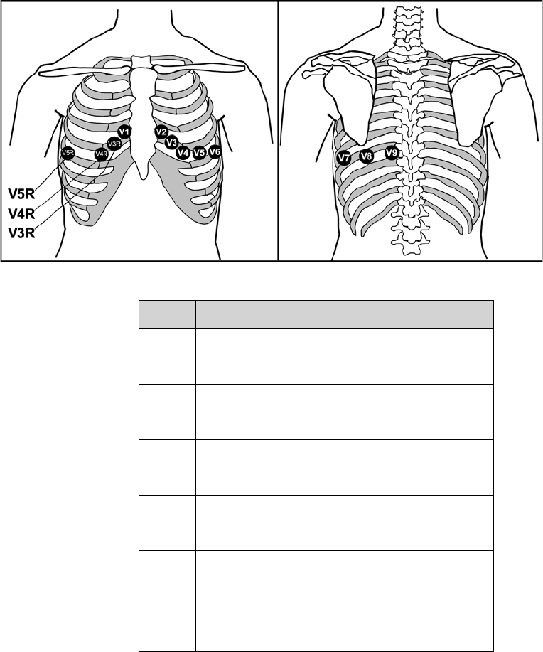
Draft - 1 Aug 08
Positioning ECG Electrodes
ECG Monitoring 6-19
Lead Placement
V1 on the fourth intercostal space at the right sternal
border
V2 on the fourth intercostal space at the left sternal
border
V3 midway between the V2 and V4 electrode
positions
V4 on the fifth intercostal space at the left
midclavicular line
V5 on the left anterior axillary line, horizontal with
the V4 electrode position
V6 on the left anterior axillary line, horizontal with
the V4 electrode position

Draft - 1 Aug 08
Positioning ECG Electrodes
6-20 ECG Monitoring
V7 on the left posterior axillary line, straight line
from V6
V8 on the left midscapular line, straight line from
V7
V9 on the left paraspinal line, straight line from V8
V3R midway between the V1 and V4R electrode
positions
V4R on the fifth intercostal space at the right
midclavicular line
V5R on the right anterior axillary line, straight line
from V4R

Draft - 1 Aug 08
Connecting the ECG Cable
ECG Monitoring 6-21
Connecting the ECG Cable
Caution
Do not insert a leadset in the transceiver during a self-test. The leadset should
be inserted either before the transceiver is powered up, or after the device has
established connection with the Information Center.
Note—When using 3- or 5-wire leadsets, alignment guides should be used to
prevent the build up of debris in open lead ports.
Step Action
1 Match the arrow on the ECG cable with the arrow on the Lead
Insertion Guide according to the lead type you have chosen, and
insert the ECG cable into the transceiver.
Important—Make sure that the cable is pushed completely into
the transceiver, otherwise the device may not detect the proper
leadset type. When correctly inserted, the colored line at the
base of the cable is not visible.
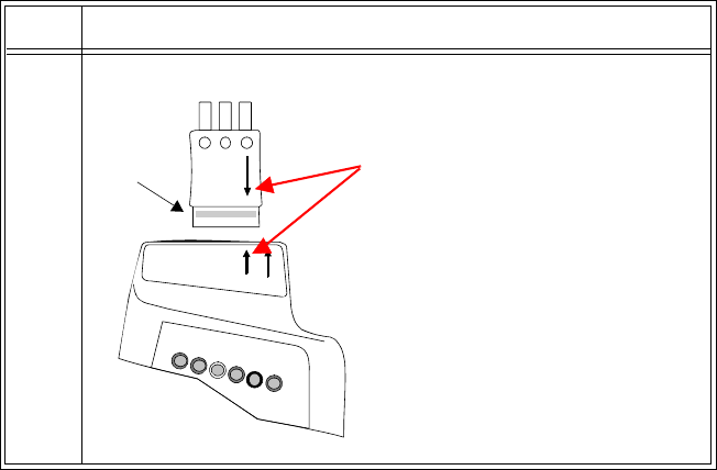
Draft - 1 Aug 08
Connecting the ECG Cable
6-22 ECG Monitoring
23-wire
Step Action
Match the arrow on the cable
with the left arrow (labeled
EASI, 3) on the Leadset In-
sertion Guide.
Note—Leadset is keyed for
only one insertion position.
EASI, 3
5.6
IntelliVue TRx
M4841A
colored
line
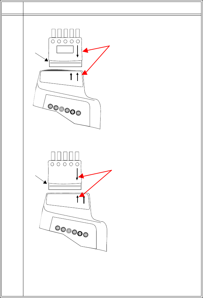
Draft - 1 Aug 08
Connecting the ECG Cable
ECG Monitoring 6-23
35-wire Standard
5-wire EASI
Note—If you are using a 5-wire leadset in both Standard and EASI
modes, insert the alignment guide into the open lead port with the
wide lip facing the leads. Then, press down firmly so that the guide
is securely under the leadset and the colored line is not visible.
Step Action
Match the arrow on the cable
with the right arrow (labeled 5,
6) on the Leadset Insertion
Guide.
EASI, 3
5.6
IntelliVue TRx
M4841A
line
colored
line
Match the arrow on the cable
with the left arrow (labeled
EASI, 3) on the Leadset In-
sertion Guide.
EASI, 3
5.6
IntelliVue TRx
M4841A
colored
line
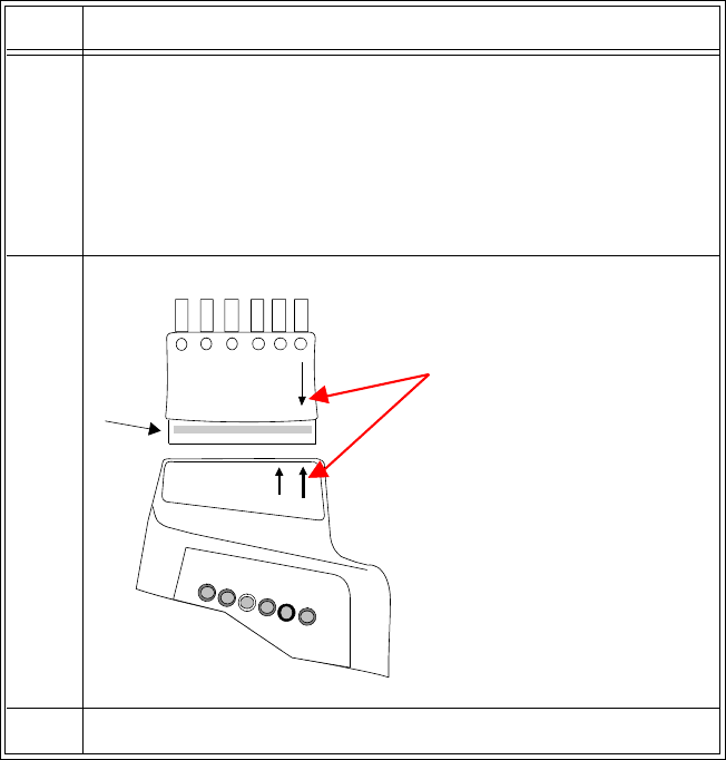
Draft - 1 Aug 08
Connecting the ECG Cable
6-24 ECG Monitoring
Cable
Disconnection When disconnecting the leadset from the transceiver, grasp the leadset block
firmly and pull free. Do not pull on the lead wires.
4 Check that the correct Electrode Indicators are lit for the leadset you
are using, and that the EASI indicator light is illuminated
appropriately. See “Verifying Electrode Connections” on page 6-25.
• When using 5-lead standard, the EASI indicator does not
illuminate.
When using EASI, the EASI indicator illuminates momentarily.
56-wire
6 For 6-lead, select the lead label(s) at the Patient Window.
Step Action
EASI, 3
5.6
IntelliVue TRx
M4841A
Match the arrow on the cable
with the right arrow (labeled
5,6) on the Leadset Insertion
Guide.
colored
line

Draft - 1 Aug 08
Verifying Electrode Connections
ECG Monitoring 6-25
Verifying Electrode Connections
The electrode indicators enable you to verify that the leads are available for the
desired monitoring. Pressing and holding the Check button enables you to view
the leadset status. During routine use of the transceiver for monitoring, all lead
indicators are off.
To verify electrode connections, use the following procedure:
Step Action
1 Press and hold the Check button for 2 seconds

Draft - 1 Aug 08
Verifying Electrode Connections
6-26 ECG Monitoring
2Expected Response:
• If 3-wire cable is attached: Red, White and Black indicators
illuminate, then all turn off.
• If 5-wire cable in Standard mode is attached: Red, White,
Black, Green & Brown indicators illuminate, then all turn off.
• If 5-wire cable in EASI mode is attached: Red, White, Black,
Green & Brown indicators illuminate, then all turn off. The
EASI indicator also illuminates briefly.
• If 6-wire cable is attached: Red, White, Black, Green, Solid
Brown and Brown/White indicators illuminate, then all turn
off.
• If all leads are off, the green indicator will be lit.
3Unexpected Response:
Any other response indicates a problem with the transceiver or lead
set.
• Check the leadset connection. The colored line should not be
visible; otherwise the wrong leadset type may be detected.
• If the INOP, INVALID LEADSET, and the corresponding
audible tone occur, the leadset inserted does not match the
transceiver’s configuration. Insert the correct leadset per the
configuration.
• Use a new leadset.
If the problem is not corrected, contact your service provider.
Step Action

Draft - 1 Aug 08
Monitoring during Leads Off
ECG Monitoring 6-27
During routine monitoring, the electrode indicators also notify you if one or
more leads are not functioning. When a "Leads Off" condition occurs, the
transceiver automatically illuminates the indicator corresponding to the missing
lead.
Note—Should the lead in the reference lead placement position (standard mode
- RL; EASI mode - green) become disconnected, the ECG signal is lost entirely.
After 10 minutes of this leads off condition, without the SpO2 sensor connected,
the transceiver will enter an RF Auto Shutoff state (if enabled). To correct the
condition, re-attach the lead to the electrode.
Monitoring during Leads Off
ECG Fallback and Extended monitoring states are supported for the transceiver
when the primary and/or secondary leads are in a "Leads Off" INOP condition.
Both of these states are entered into after 10 seconds of "Leads Off" in an
attempt to maintain monitoring and arrhythmia analysis.
ECG
Fallback ECG Fallback occurs when the primary lead is in "Leads Off" for 10 seconds
and a secondary lead is available.
Multilead
Analysis If there is a "Leads Off" technical alarm in the primary lead for > 10 seconds,
the active secondary lead becomes the primary lead. The arrhythmia algorithm
switches the leads on the display, but relearn does not occur. When the "Leads
Off" condition is corrected, the leads are switched back to their original state.
Single Lead
Analysis For single lead analysis, if there are two leads available, the secondary lead is
made the primary lead until the "Leads Off" condition is corrected. The
arrhythmia algorithm performs a relearn using the available lead.

Draft - 1 Aug 08
Monitoring during Leads Off
6-28 ECG Monitoring
Fallback for
EASI If one of the derived EASI leads is in a technical alarm condition, a flat line is
displayed. After 10 seconds, the directly acquired EASI AI, AS, or ES lead,
depending on which is available, is displayed with the label “ECG”. Arrhythmia
relearn is performed with transition to or from EASI Fallback monitoring using
the available lead(s).
Relearning Whenever there is a "Leads Off" condition, the arrhythmia algorithm performs a
Relearn using the available leads.
WarningWarning
Since Relearn happens automatically, if learning takes place during
ventricular rhythm, the ectopics can be incorrectly learned as the normal
QRS complex. This can result in missed detection of subsequent events of
V-Tach and V-Fib. For this reason, you should:
1. Respond promptly to any technical alarm.
2. Ensure that the arrhythmia algorithm is labeling beats correctly.
Using EASI Leads to Troubleshoot
If there is artifact in the ECG waves or a "Cannot Analyze ECG" technical
alarm condition is in effect, you can use the three EASI leads to troubleshoot at
the Information Center:
1. Click 12-Lead ECG on the Patient Window, then on 3 EASI Leads.
2. The three directly acquired EASI leads will be displayed so that you can
determine which electrodes are causing the problem and need to be
replaced.

Draft - 1 Aug 08
Optimizing ECG Measurement Performance
ECG Monitoring 6-29
Optimizing ECG Measurement Performance
WarningWarning
Telemetry should not be used for primary monitoring in applications
where the momentary loss of the ECG is unacceptable.
No matter how good a wireless network design is, a telemetry system will
always experience occasional loss of radio communications, resulting in ECG
waveform dropouts. A telemetry system will never be as reliable as a hardwired
bedside monitor that transmits its signal through a wire. If occasional loss of
ECG monitoring is not acceptable for certain patients, they should be connected
to a hardwired bedside monitor.
Smart Hopping technology alleviates most of the problems associated with
legacy telemetry technologies. Reception problems are less frequent, because
Smart Hopping avoids interference and moves to a different access point if the
signal strength is too low. The level of radio frequency activity is always
fluctuating in the environment. If the level becomes high enough to
significantly interfere with transceiver operation, the system responds by
moving to another “cleaner” area where there is less activity.
The effect of interference on the IntelliVue Telemetry System ranges from a
momentary loss of ECG to complete inoperability, and can be caused by many
sources. The strength, frequency, and proximity of the source of interference to
the transceiver or the access point are factors that determine the degree of
severity. In cases where the source of interference can be identified, corrective
action can be taken. For example, removing or moving away from the source of
interference will increase the equipment's dependability.
Draft - 1 Aug 08
Optimizing ECG Measurement Performance
6-30 ECG Monitoring
Clinicians will tend to see more motion related artifact on the ECG of
ambulatory patients than on patients that are restricted to a bed. Proper skin
preparation and electrode application are very important in reducing this
problem.
Problems with the ECG signal stem from two main sources:
1. Frequency-related sources resulting in dropouts from signal disturbances
and loss of signal.
2. Patient-related sources with noise on the waveform caused by clinical
considerations such as poor skin prep, dry electrodes, and poor electrode
adhesion, as well as by patient motion and muscle artifact.
Even in complex situations where problems overlap, most of the time you’ll be
able to greatly enhance performance by taking corrective action.
Monitoring
Considerations • Patient should be restricted to the designated coverage area. Monitoring
performance will degrade if patients go outside the radius of coverage of
the receiving wireless network.
• A patient location strategy is critical to a telemetry system. If a life-
threatening event occurs, the clinician must be able to locate the patient
quickly. The importance of this increases as the coverage area increases.
• Frequency management is the responsibility of the hospital. Philips
Medical System has no control over the RF environment in the hospital.
If interference exists at the operating frequencies of the telemetry
equipment, telemetry performance will be affected. Careful selection of
frequencies for all wireless devices used within a facility (transceivers,
other wireless medical devices, etc.) is important to prevent interference
between them.
Dropouts Because the IntelliVue Telemetry System is a wireless system, under certain
frequency conditions dropouts can occur. Dropouts result from a weak signal or
RF interference, and appear on the waveform when the signal "drops" to the
bottom of the channel for a minimum of 200 ms. If dropouts are frequent
enough to affect the heart rate count, the "Cannot Analyze ECG" or "Cannot
Analyze ST" technical alarm occurs. If there are enough dropouts to cause
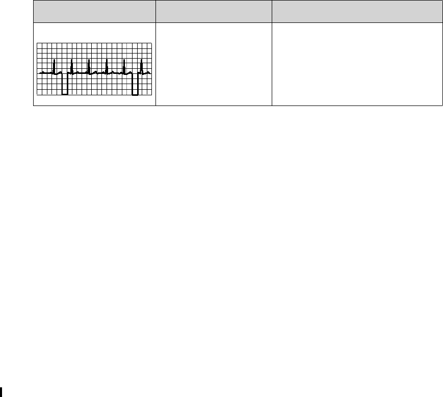
Draft - 1 Aug 08
Optimizing ECG Measurement Performance
ECG Monitoring 6-31
disassociation/reassociation with the Information Center, events in the Clinical
Review application can reflect loss of data for up to 1 minute in the worst case.
Signal Strength The IntelliVue Telemetry System is custom designed for your site, so reliable
signal reception is only possible where there are receiving access points. When
the signal is too low, the following technical alarms can occur:
• "Cannot analyze ECG"
• "Cannot analyze ST
• "Tele Weak signal"
•"No signal"
Corrective Action
1. Check the location of the patient. If the patient is out of range, return the
patient to the specified coverage area.
2. If the patient is intentionally out of the coverage area, put telemetry in
Standby Mode. See “Standby Mode” on page 4-4.
3. If the patient is in the coverage area and is stationary, try moving the
transceiver about 15 cm (6 inches).
4. Check for INOP and information signals at the Information Center.
5. Check for interference activity in other sectors at the Information Center
to see if the problem is occurring with other transceivers.
6. If the problem is persistent, call service.
Radio
Frequency
Interference
Radio frequency (RF) interference is caused by other devices that intrude into
the transmitted electrical signal. You are probably familiar with electrical
interference in our homes and cars when it causes signal loss or static with cell
phones. This same type of interference can occur with the transmitted telemetry
signal even though the IntelliVue Telemetry System is designed to resist these
Problem Cause Remedy
Dropouts Low signal strength
RF interference
See “Signal Strength” below.
See “Radio Frequency Interference”
below.

Draft - 1 Aug 08
Optimizing ECG Measurement Performance
6-32 ECG Monitoring
effects and Smart-hopping enables the system to avoid most instances of
interference.
The 2.4 GHz ISM band used by the ITS4850A IntelliVue Telemetry System is
used by many different radio technologies, (e.g. microwave ovens, wireless
phones, Bluetooth devices). Therefore, there is increased potential for
interference. The system has the ability to detect whether the spectrum is too
congested. When detected, a "Wireless Monitoring Loss - Call Service" alert is
issued at the Information Center.
Corrective Action
1. To improve performance, the source of the interference must be identified
and eliminated. Try moving or removing other wireless devices
transmitting in the Wireless Medical Telemetry Service (WMTS - USA
only). Such devices can be identified by the presence of an antenna and/
or the following symbol:
:
Important—The IntelliVue Telemetry System emits radio frequencies that can
affect the operation of other devices. Contact the manufacturer of other
equipment for possible susceptibility to these frequencies.
Muscle and
Movement
Artifact
Muscle and movement artifact, respiratory variation, as well as poor electrode
contact, inadequate skin preparation, and other patient-related factors can also
affect interference with the ECG signal. Good clinical practice can have a
significant effect on the quality of ECG monitoring.
Corrective Action
Use the following table to help you troubleshoot the most common sources of
physiologically-caused ECG noise.
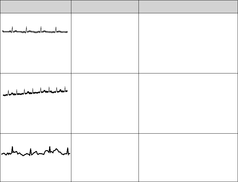
Draft - 1 Aug 08
Optimizing ECG Measurement Performance
ECG Monitoring 6-33
Problem Cause Remedy
60-Cycle (AC) Interference Poor electrode placement.
Possible non-grounded
instrument near patient.
Re-apply electrodes, using good skin
preparation (see “Positioning ECG
Electrodes” on page 6-10).
Disconnect electrical appliances near
patient (one at a time) by pulling wall
plugs, to determine faulty grounding.
Have engineering check grounding.
Muscle Artifact Tense, uncomfortable
patient.
Poor electrode placement.
Tremors.
Diaphoresis.
Make sure patient is comfortable.
Check that electrodes are applied on
flat non-muscular areas of the torso;
apply fresh electrodes if necessary,
using good skin preparation (see
“Positioning ECG Electrodes” on page
6-10).
Irregular Baseline Poor electrical contact.
Respiratory interference.
Faulty electrodes.
Dry electrodes.
Re-apply electrodes, using good skin
preparation (see “Positioning ECG
Electrodes” on page 6-10).
Move electrodes away from areas with
greatest movement during respiration.

Draft - 1 Aug 08
Optimizing ECG Measurement Performance
6-34 ECG Monitoring
Baseline Wander Movement of patient.
Improperly applied
electrodes.
Respiratory interference.
Make sure patient is comfortable.
Re-apply electrodes, using good skin
preparation (see “Positioning ECG
Electrodes” on page 6-10). Check that
patient cable is not pulling electrodes.
Move electrodes away from areas with
greatest movement during respiration.
Poor Electrode Contact Loose electrodes.
Defective cables.
Leadset not firmly
connected.
Change electrodes, using good skin
preparation (see “Positioning ECG
Electrodes” on page 6-10).
Replace cables.
Problem Cause Remedy
Draft - 1 Aug 08
ST/AR Arrhythmia Monitoring 7-1
Introduction
7
ST/AR Arrhythmia
Monitoring
This chapter describes the ST/AR algorithms used for telemetry at the IntelliVue
Information Center. It includes the following sections:
• ST/AR Arrhythmia Algorithm . . . . . . . . . . . . . . . . . . . . . . . . . . . . . . . 7-2
• ST/AR ST Segment Algorithm. . . . . . . . . . . . . . . . . . . . . . . . . . . . . . . 7-7
• ST/AR QT Interval Algorithm . . . . . . . . . . . . . . . . . . . . . . . . . . . . . . 7-14

Draft - 1 Aug 08
ST/AR Arrhythmia Algorithm
7-2 ST/AR Arrhythmia Monitoring
ST/AR Arrhythmia Algorithm
Indications
for Use The ST/AR Arrhythmia Algorithm is indicated for use in instances where the
clinician decides to monitor cardiac arrhythmias of adult and pediatric patients
and/or the ST segment of adult patients to gain information for treatment,
monitor the adequacy of treatment, or to exclude causes of symptoms.
Safety
Information
WarningWarning
During complete heart block or pacemaker failure (to pace or capture), tall
P-waves (greater than 1/5 of the average R-wave height) can be erroneously
counted by the arrhythmia algorithm, resulting in missed detection of
cardiac arrest.
WarningWarning
Learning
If you initiate learning during ventricular rhythm, the ectopics can be
incorrectly learned as the normal QRS complex. This can result in missed
detection of subsequent events of V-Tach and V-Fib.

Draft - 1 Aug 08
ST/AR Arrhythmia Algorithm
ST/AR Arrhythmia Monitoring 7-3
WarningWarning
Relearning
Arrhythmia relearning is initiated whenever the transceiver is powered
down for one minute or longer or whenever it is directly connected/
disconnected to an IntelliVue MP5 Patient Monitor. Be sure to check your
patient’s arrhythmia annotation for accuracy whenever relearn has
occurred.
Since Relearn happens automatically, if learning takes place during
ventricular rhythm, the ectopics can be incorrectly learned as the normal
QRS complex. This can result in missed detection of subsequent events of
V-Tach and V-Fib. For this reason, you should:
1. Respond promptly to any technical alarm.
2. Ensure that the arrhythmia algorithm is labeling beats correctly.
When using EASI ECG monitoring, Relearn happens automatically when
there is a LEADS OFF technical alarm. If learning takes place during
ventricular rhythm, the ectopics can be incorrectly learned as the normal
QRS complex. This can result in missed detection of subsequent events of
V-Tach and V-Fib. Be sure to check the beat labels and initiate a relearn to
correct.
1. Respond to the technical alarm [for example, reconnect the electrode(s)].
2. Ensure that the arrhythmia algorithm is labeling beats correctly.
For Paced
Patients
WarningWarning
Some pace pulses can be difficult to reject. When this happens, the pulses
are counted as a QRS complex, and could result in an incorrect HR and
failure to detect cardiac arrest or some arrhythmias. Keep pacemaker
patients under close observation.

Draft - 1 Aug 08
ST/AR Arrhythmia Algorithm
7-4 ST/AR Arrhythmia Monitoring
WarningWarning
For paced patients who exhibit only intrinsic rhythm, the monitor can
erroneously count pace pulses as QRS complexes when the algorithm first
encounters them, resulting in missed detection of cardiac arrest. The risk of
missing cardiac arrest can be reduced by monitoring these patients with the
low heart rate limit at or slightly above the basic/demand pacemaker rate.
A low heart rate alarm alarms you when the patient begins pacing. Proper
detection and classification of the paced rhythm can then be determined.
WarningWarning
When an external pacemaker is being used on a patient, arrhythmia
monitoring is severely compromised due to the high energy level in the
pacer pulse. This can result in the arrhythmia algorithm’s failure to detect
pacemaker non-capture or asystole.
WarningWarning
It is possible that pacemaker pulses will not be detected when the ECG
analog output of a defibrillator is plugged into a bedside monitor. This can
result in the arrhythmia algorithm’s failure to detect pacemaker non-
capture or asystole.
WarningWarning
Always verify that your patient’s paced setting at the Information Center
accurately reflects the patient’s status.
Intended
Use The intended use of the ST/AR basic arrhythmia analysis algorithm is to monitor
the patient’s ECG for heart rate and ventricular arrhythmias and to produce
events/alarms simultaneously for one or more ECG leads. The arrhythmia
algorithm is effective when monitoring both paced and non-paced patients in a
clinical environment.

Draft - 1 Aug 08
ST/AR Arrhythmia Algorithm
ST/AR Arrhythmia Monitoring 7-5
ST/AR
Arrhythmia
Analysis
For information on arrhythmia detection, refer to the following documentation:
•ST/AR Algorithm - Arrhythmia Monitoring Application Note,
#452298193051
•IntelliVue Information Center Instructions for Use and Online Help
IntelliVue Telemetry does not have a dedicated cardiotach. Instead, the
arrhythmia cardiotach at the Information Center is used. Therefore, the ST/AR
Arrhythmia algorithm is always on for all IntelliVue Telemetry patients, and
cannot be turned off.
ST/AR provides Heart Rate and PVC Rate numerics and alarm detection for the
conditions listed in the following table. There are two detection levels: Basic and
Enhanced. Enhanced includes the Basic alarms.
Basic & Enhanced Arrhythmia Detection
Basic Arrhythmia Detection Enhanced Arrhythmia Detection
Asystole Non-Sustain VT
V-Fib/Tach Vent Rhythm
V-Tach Run PVCs
Brady yyy < xxx Pair PVCs
Tachy yyy > xxx Pause
HR yyy > xxx Missed Beat
HR yyy < xxx SVT
PVCs > xxx/min R-on-T PVCs
Pacer Not Capturing Vent Bigeminy
Pacer Not Pacing Vent Trigeminy
Multiform PVCs
Afib
Irregular HR

Draft - 1 Aug 08
ST/AR Arrhythmia Algorithm
7-6 ST/AR Arrhythmia Monitoring
Beat classification determined by the ST/AR algorithm is shown on the primary
delayed wave in the Arrhythmia Analysis window at the Information Center. To
access this window, select Arrhythmia Analysis from the Patient Window.
The annotation requires clinical validation of the analyzed heart rhythm. If the
analysis is inaccurate, perform a relearn of the rhythm.
When monitoring is initiated, when the Primary Wave is changed, or if Relearn
is selected, a question mark (?) is displayed next to HR and the annotation “L”
appears on the annotated wave until the HR is calculated and the rhythm is
learned.
Annotation Beat Classification Display
Color
AArtifact Blue
IInoperative Red
LLearning Red
MMissed Beat Red
NNormal Blue
PPaced Blue
SSupraventricular Premature Blue
VVentricular Premature Red
?Questionable Red
'Pacer Spike Blue
"Biventricular Pacer Spike Blue

Draft - 1 Aug 08
ST/AR ST Segment Algorithm
ST/AR Arrhythmia Monitoring 7-7
ST/AR ST Segment Algorithm
Intended
Use The intended use of the ST/AR ST Analysis algorithm is to monitor an adult
patient’s ECG for ST segment elevation or depression and produce events/
alarms for all possible ECG leads. The ST Analysis algorithm is capable of
monitoring paced and non-paced adult patients.
Note—The ST Analysis algorithm does not analyze ventricularly paced or
ventricular ectopic beats.
WarningWarning
This device provides ST level change information; the clinical significance
of the ST level change information needs to be determined by a physician.
The ST/AR ST algorithm at the Information Center monitors ST segment
elevation or depression for each available telemetry ECG lead and produces
events/alarms simultaneously. ST values update with every measurement period
and enunciate, depending upon the severity of the change, events and alarms as
they are detected.
The ST/AR ST algorithm is approved for use only with non-paced and atrially-
paced adult telemetry-monitored patients. With EASI monitoring, ST analysis is
performed on up to 12 leads, and an additional value of ST index is calculated
and displayed (see “EASI ST Analysis” on page 7-9). Assessment of EASI-
derived 12-lead ST measurement is recommended for adult patients that meet
the following parameters:
• Ages: 33-82 years
• Heights: 147 to 185 cm (58 to 73 in)
• Weights: 53 to 118 kg (117 to 261 lbs)
• Height to Weight Ratios: 1.41 to 2.99 cm/kg (0.25 to 0.54 in/lb)
All ST analysis and ST alarms for telemetry patients are performed by the
Information Center.
For additional information on ST monitoring, refer to the following
documentation:
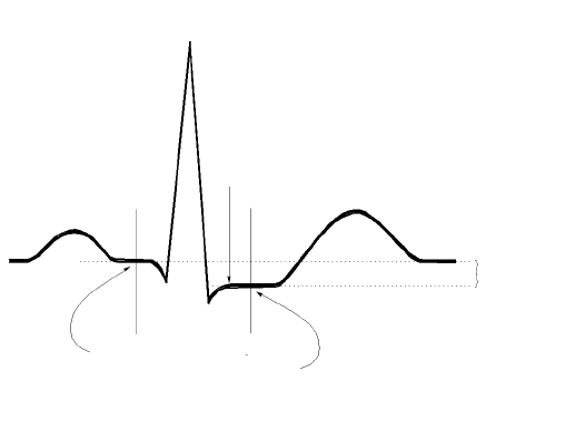
Draft - 1 Aug 08
ST/AR ST Segment Algorithm
7-8 ST/AR Arrhythmia Monitoring
•ST/AR Algorithm - ST Segment Monitoring Application Note,
#452298192851
•IntelliVue Information Center Instructions for Use and Online Help
The
Measurement The ST measurement for each beat complex is the vertical difference between
two measurement points. The isoelectric point provides the baseline for the
measurement and the ST point provides the other measurement point. It is
positioned with reference to the J-point.
Algorithm
Processing ST analysis analyzes ECG signals to classify the heart beats. Only beats
classified as normal or Supraventricular (atrially paced) are used to calculate ST
elevations and depressions.
The ST/AR ST algorithm processing includes special ST filtering, beat selection
and statistical analysis, calculation of ST segment elevations and depressions,
and lead reconstruction and wave generation.
When ST analysis is being performed on two leads, the averaged derived and
reconstructed ST waves and associated ST segment values are given for up to
six leads, depending on the type of patient cable:
• 3-wire: one lead
R-WAVE PEAK
AT 0 MSEC
J POINT
ISO ELECTRIC
POINT
DEFAULT =
-80 MSEC
MEASUREMENT
POINT
DEFAULT =
J+60 MSEC
DIFFERENCE =
ST VALUE
P
Q
S
ST
T

Draft - 1 Aug 08
ST/AR ST Segment Algorithm
ST/AR Arrhythmia Monitoring 7-9
• 5-wire: up to two leads if monitoring a chest and a limb lead
• 5-wire: up to six leads if monitoring two limb leads
• 5-wire: up to 12 leads if monitoring using EASI
• 6-wire: up to 8 leads if monitoring two limb leads and two chest leads
Note—No ST analysis is done on a patient if an electrode falls off.
Displayed
ST Data ST data displays as values in the Patient Sector and Patient Window. A positive
value indicates ST segment elevation; a negative value indicates ST segment
depression. You can view ST data in ST Review, Trend Review, and Event
Review windows.
EASI ST
Analysis The Information Center generated ST values presented in the patient sector and
Patient Window for EASI derived leads is STindx (ST Index). STindx is a
summation of three ST segment measurements, using the leads that can indicate
ST segment changes in the different locations of the heart:
• anterior lead V2
• lateral lead V5
• inferior lead aVF
ST Operation
Turning ST
Monitoring On/
Off
The ST Setup Window allows you to turn ST monitoring on or off for all
available ECG leads.
To turn ST monitoring on at the Information Center, perform the following
steps:
You would turn ST monitoring off if:
Step Action
1From the Patient Window, click the All Controls button.
2From the All Controls Window, click the ST Setup button.
3From the ST Setup Window, click ST On.
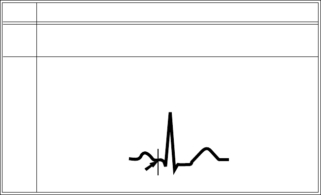
Draft - 1 Aug 08
ST/AR ST Segment Algorithm
7-10 ST/AR Arrhythmia Monitoring
• You are unable to get any lead that is not noisy.
• Arrhythmias such as atrial fib/flutter cause irregular baseline.
• The patient is continuously ventricularly paced.
• The patient has left bundle branch block.
Adjusting ST
Measurement
Points
The ST Setup Window enables you to adjust the ST measurement points to
ensure accurate data.
There are three measurement cursors:
• The ISO measurement cursor positions the isoelectric point in relation to
the R-wave peak.
• The J-point cursor positions the J-point in relation to the R-wave peak.
The purpose of the J-point is to correctly position the ST measurement
point.
• The ST measurement cursor positions the ST point a fixed distance from
the J point.
Note—The ST measurement points may need to be re-adjusted if the patient's
heart rate or ECG morphology changes significantly.
Perform the following steps at the Information Center to adjust the ST
measurement points:
Step Action
1Access the ST Setup window by clicking on the All Controls button
in the Patient Window, then clicking on the ST Setup button.
2If you need to adjust the ISO (isoelectric) point, place the cursor
over the ISO button to access the adjustment arrows. Then use the
arrows to position the bar in the middle of the flattest part of the
baseline (between the P and Q waves or in front of the P wave).
T
R
P
ISO
point QS
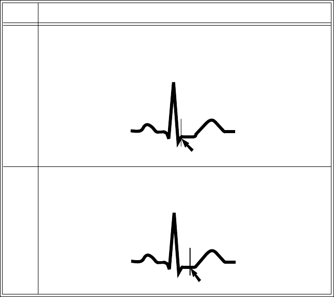
Draft - 1 Aug 08
ST/AR ST Segment Algorithm
ST/AR Arrhythmia Monitoring 7-11
Establishing
ST Reference
Beats
(Baseline)
After adjusting the measurement points, you can establish baseline reference
beats for all available leads in the ST Review window at the IntelliVue
Information Center. Reference beats enable you to compare waveform changes,
for example from admission, or prior to or after treatment. The reference
continues to be saved beyond the 24 hour review window, but you can update it
to any beat within the last 24 hours. Please refer to the IntelliVue Information
Center Instructions for Use or Online Help for directions.
3Adjust the J point, if necessary, by placing the cursor over the J-
point button to access the adjustment arrows. Then use the arrows to
position the bar at the end of the QRS complex and the beginning of
the ST segment.
4Adjust the ST point, if necessary, by using the J point as an
“anchor” and placing the bar at the midpoint of the ST segment.
Choices are J+0, J+20, J+40, J+60, or J+80.
Step Action
T
R
P
S
QJ point
T
R
P
S
QST point
Draft - 1 Aug 08
ST/AR ST Segment Algorithm
7-12 ST/AR Arrhythmia Monitoring
ST Alarm
Settings All IntelliVue Information Center alarm settings (limits and on/off status) have
unit default settings. The IntelliVue Information Center however, lets you set the
high and low ST alarm limits for individual patients based on:
• Your assessment of the patient's clinical condition.
• Unit protocols.
• Physician orders or medication specified limits.
You can make the following adjustments to ST alarm limits to accommodate the
clinical condition of individual patients:
• Turn all alarms off/on.
• Adjust the alarm limits:
– to specific high and low limits
– to Smart Limits (see the IntelliVue Information Center Instructions
for Use for information on Smart Limits)
– back to unit default settings.
You adjust the ST alarm limits in the ST Alarms Window. Each ST parameter
has its own alarm limit. The alarm is triggered when the ST value exceeds its
alarm limit for more than 1 minute. The alarm will be a yellow alarm.
When more than one ST parameter is in alarm, only one alarm message displays.
For multilead alarms when using an EASI transceiver, an alarm is generated if
two or more ST leads exceed the alarm limits. The default setting is +/-1.0. The
alarm message indicates the two leads that are in greatest violation of the limits,
for example, “**MULTI ST AVR, V6”. If another lead becomes deviant, the
message changes but it is considered the same alarm (no new alarm sounds and
it is not listed as a new event).
See “Physiologic Alarms” on page 5-4 for a list of all ST alarms.
See the IntelliVue Information Center Instructions for Use for specifics on alarm
management and behavior.

Draft - 1 Aug 08
ST/AR ST Segment Algorithm
ST/AR Arrhythmia Monitoring 7-13
Adjusting ST
Alarms Make adjustments to ST alarms on the ST Alarms window at the Information
Center.
Step Action
1From the Patient Window, select the All Controls button.
2 From the All Controls window, select the ST Alarms button under
Alarm Management and Setup.
3In the ST Alarms window, adjust alarms as needed. Choices for
setting the ST alarm limits are:
Unit Settings—Click on this button if want to have the specific
limits that are pre-set for your unit.
Smart Limits—Click on this button to set high and low limits around
your patient's current ST value. The difference above and below the
patient's ST value are pre-set for your unit.
Note—Smart Limits can be configured to automatically be activated
when the patient is connected. See the IntelliVue Information Center
Instructions for Use for additional information on using smart limits.
Set the high and low alarm limits based on your assessment of the
patient's clinical condition, unit protocols, or physician orders or
medication specified limits. A good guideline is + 1.0 mm or - 1.0
mm from the patient's ST, or follow your unit protocol.

Draft - 1 Aug 08
ST/AR QT Interval Algorithm
7-14 ST/AR Arrhythmia Monitoring
ST/AR QT Interval Algorithm
Intended
Use The intended use of the ST/AR QT/QTc analysis is for use by the physician in
the risk assessment process indicated for pediatric and adult patients with and
without symptoms of arrhythmia. QT measurement is intended to be used by
qualified health professionals in hospital or clinical environments. Composite
QT (single or multi-lead derived) measures the interval only and is not intended
to produce any interpretation or diagnosis of those measurements.
WarningWarning
The device provides QT and QTc interval change information; the clinical
significance of the QT and QTc interval change information should be
determined by a clinician.
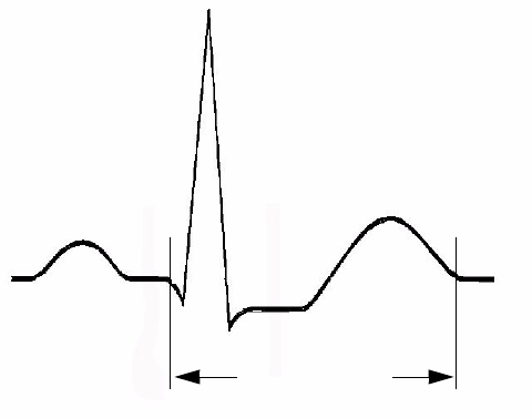
Draft - 1 Aug 08
ST/AR QT Interval Algorithm
ST/AR Arrhythmia Monitoring 7-15
What is QT
Interval
Monitoring
Of special concern for QT monitoring is the administration of QT prolonging
drugs to patients identified with risk factors for Torsade de Pointe. Females,
older patients and patients with bradycardia, impaired left ventricular function
(ischemia, left ventricular hypertrophy), hypokalemia and hypomagnesemia are
in this increased risk category.
QT interval monitoring can assist in the detection of prolonged QT interval
syndrome.The QT interval in an ECG lead is the time interval from the onset of
the earliest deflection in the QRS complex to the end of the T wave. For
patients being monitored by an IntelliVue Telemetry System device, the
Information Center measures the QT values once every minute during startup,
during the learning phase and on lead mode change. After that the Information
Center updates the QT values every five minutes.
The QT interval has an inverse relationship to heart rate. Faster heart rates
shorten the QT interval and slower heart rates prolong the QT interval. To
correct the QT interval for heart rate the Information Center uses the Bazett
correction formula by default. Your system, however, may be set up to use the
Fridericia correction formula as an alternative. The heart rate corrected QT
interval is abbreviated as QTc.
R
P
QS
T
QT Interval

Draft - 1 Aug 08
ST/AR QT Interval Algorithm
7-16 ST/AR Arrhythmia Monitoring
QT
Definitions Measurement Definition
QT QT interval in milliseconds. The QT interval is the
time between the beginning of the Q wave and the
end of the Twave.
QTc QTc represents the heart rate corrected QT interval.
By default, the Information Center uses the Bazett
correction formula to correct the QT interval for
heart rate. Your system, however, may be set up to
use the Fridericia correction formula.
dQTc The difference between the current QTc value and
the QTc baseline value.
QT-HR The heart rate used to calculate QTc

Draft - 1 Aug 08
ST/AR QT Interval Algorithm
ST/AR Arrhythmia Monitoring 7-17
QT Alarms
Alarm Definition
**QTc High The QTc high limit alarm is a long yellow alarm that
occurs when there are two consecutive 5 minute QTc
values above the set alarm limit.
**dQTc High The dQTc alarm is a long yellow alarm that occurs
when the difference between the current value and
the baseline value exceeds the set limit for two
consecutive 5 minute dQTc values. The dQTc alarm
has a lower priority than the QTc High alarm.
Cannot Analyze QT When there are two consecutive invalid 5 minute
values the Information Center generates a Cannot
Analyze QT soft INOP and displays a question mark
(?) for the QT parameter value. The Information
Center displays the Cannot Analyze QT INOP
without the question mark during initial startup and
during the learning phase.

Draft - 1 Aug 08
How the QT Analysis Algorithm Works
7-18 ST/AR Arrhythmia Monitoring
How the QT Analysis Algorithm Works
The Information Center measures the QT values once every minute during
startup. Subsequently, the Information Center updates the QT values every five
minutes. Normal or atrial paced beats and beats with a similar morphology are
averaged to form a representative waveform for further processing. Normal
beats followed by a premature QRS will be excluded from the measurements to
prevent the premature beat from obscuring the end of the T-wave. If the
algorithm cannot form a representative waveform, for example because the
morphology of the beats is too varied, the Information Center generates a
Cannot Analyze QT INOP when it detects two consecutive invalid 5 minute
values. This is also the case if normal beats have been falsely labelled so that the
algorithm does not have enough valid beats to make QT measurements. No QT
value is calculated if the QT-HR is >150 bpm (Adult) or >180 bpm (Pedi/Neo).
Because of the different algorithm approaches, a QT/QTc measurement from a
diagnostic 12-lead program may differ from the realtime measurement.
For QT interval monitoring to be effective, basic or enhanced arrhythmia
monitoring must be on.
Adjusting
QT Settings For patients being monitored by an IntelliVue Telemetry System device you can
adjust QT settings in the QT Setup window at the Information Center. If the
patient is monitored by an IntelliVue Patient Monitor, QT/QTc analysis is
provided by the IntelliVue Patient Monitor. Adjust QT settings at the bedside.
To adjust the settings at the Information Center:
Step Action
1 Access the QT Setup window by selecting the QT Setup button in
the All Controls window.
2 Make the adjustments on the QT Setup window. The table below
describes each of the available adjustments.

Draft - 1 Aug 08
How the QT Analysis Algorithm Works
ST/AR Arrhythmia Monitoring 7-19
Adjustment Description
Turn QT Analysis On/Off Turn QT analysis on by clicking in the QT
Analysis On check box. QT analysis is on
when a checkmark displays in the check box.
When the QT measurement is on, a QT status
message is displayed in the QT Setup window,
along with the current values for QT, QTc, dQTc
and QT-HR. The lead labels indicating the leads
used to calculate the baseline and current values
also appear.
Note—Turning QT analysis off does not clear
the baseline value. This allows you to turn QT
analysis off during prolonged arrhythmias, such
as bigeminy, without losing the baseline.

Draft - 1 Aug 08
How the QT Analysis Algorithm Works
7-20 ST/AR Arrhythmia Monitoring
Select the QT Lead The QT Lead field allows you to select which
leads to analyze when calculating the QT
parameters. To select the desired lead by
clicking on the QT Lead drop down arrow then
highlighting the lead from the list that displays.
Choose:
•All if you want a global QT measurement
based on all available leads. For standard
placement leads I, II, III, V and V1 through
V6 are used. For EASI placement directly
acquired AI, AS, and ES leads are used.
Note—This may include leads that are not being
stored.
•Primary if you want to use the primary
lead for the QT measurement. If the primary
lead becomes unavailable or is changed the
QT measurement continues with the new
primary lead.
• A single lead from the list to use that lead
for QT measurement. If the lead you select
becomes unavailable QT monitoring stops.
Note—The V7, V8, V9, V3R, V4R or V5R
leads are not available for single lead
selection. These leads are processed,
however, when you select Primary in the
QT Lead field.
Adjustment Description

Draft - 1 Aug 08
How the QT Analysis Algorithm Works
ST/AR Arrhythmia Monitoring 7-21
Set the QT Baseline To quantify changes in the QTc value you can
set a QTc baseline. Select the Set QT Baseline
button to replace the baseline QTc value with the
current QTc value. If a baseline has not been set
the Information Center sets the baseline to the
first valid value after measuring QT for five
minutes. Setting a new baseline discards the
previous baseline.
Notes—
• Since the dQTc alarm is based on the
difference between the baseline and the
current value, setting an inappropriate new
baseline may prevent a dQTc alarm from
being generated.
• Turning QT analysis off does not clear the
baseline value. This allows you to turn QT
analysis off during prolonged arrhythmias,
such as bigeminy, without losing the
baseline.
• Discharging a patient clears the baseline.
Adjustment Description

Draft - 1 Aug 08
How the QT Analysis Algorithm Works
7-22 ST/AR Arrhythmia Monitoring
Turning QT Alarm On/Off There are two QT long yellow alarms (**); QTc
High and dQTc High. The QTc High alarm
occurs when two consecutive 5 minute QTc
values are above the set alarm limit. The dQTc
alarm occurs when the difference between the
current value and the baseline value exceeds the
set limit for two consecutive 5 minute dQTc
values.
Turn the QTc or dQTc alarm on by placing a
checkmark in the checkbox next to the QTc
High or dQTc High field. The Alarm is off
when no checkmark displays in the checkbox.
Adjusting QT Alarm
Limits Set the high alarm limits based on your
assessment of the patient's clinical condition,
unit protocols, physician orders or medication
specified limits.
Normal Values for Adults:
• Men: QTc <420 milliseconds.
• Women: QTc <430 milliseconds.
To set the QTc or dQTc alarm limits:
1. Turn the QTc or dQTc alarm on by placing
a checkmark in the checkbox next to the
QTc High or dQTc High field.
2. Use the appropriate up and down arrow to
obtain the desired limit.
Adjustment Description

Draft - 1 Aug 08
How the QT Analysis Algorithm Works
ST/AR Arrhythmia Monitoring 7-23
Limitations
for QT
Monitoring
Some conditions may make it difficult to achieve reliable QT monitoring. When
this occurs the CANNOT ANALYZE QT INOP message displays at the
Information Center, along with a QT STATUS message. Some conditions that
may make reliable QT monitoring difficult include:
• T-Wave Detection Limitations.
Flat T-wave, atrial Fibrillation or atrial Flutter and prominent U-waves
can make QT monitoring difficult. For these cases you should select All
as the QT Lead on the QT window. The Information Center will use the
lead or leads that have a T-wave with sufficient amplitude and can be
detected. Alternatively select a single lead with a good T- wave amplitude
and no visible flutter activity and without a predominant U-wave or P-
wave.
•QRS Changes
QRS changes such as widened QRS can affect QT monitoring. If a long
QTc is observed verify that is not caused by QRS widening.
•Rhythm and Rate Limitations
Rhythm and rate limitations such as high heart rate (> 150 beats/min for
adults patients or > 180 beats/min for pediatric or neonatal patients),
paced rhythm and bigeminy rhythm can make reliable QT monitoring
difficult. If rhythm is sustained you may want to consider turning QT
interval monitoring off.
Draft - 1 Aug 08
How the QT Analysis Algorithm Works
7-24 ST/AR Arrhythmia Monitoring
Draft - 1 Aug 08
SpO2 Monitoring 8-1
Introduction
8
SpO2 Monitoring
This chapter provides an introduction to the SpO2 measurement and its
application. It includes the following sections:
•SpO
2 Safety Information . . . . . . . . . . . . . . . . . . . . . . . . . . . . . . . . . . . 8-2
• Pulse Oximetry Measurement. . . . . . . . . . . . . . . . . . . . . . . . . . . . . . . . 8-5
• Selecting a SpO2 Sensor. . . . . . . . . . . . . . . . . . . . . . . . . . . . . . . . . . . . 8-7
• Applying the Sensor . . . . . . . . . . . . . . . . . . . . . . . . . . . . . . . . . . . . . . 8-11
• Connecting the SpO2 Cable . . . . . . . . . . . . . . . . . . . . . . . . . . . . . . . . 8-15
•Measuring SpO
2 . . . . . . . . . . . . . . . . . . . . . . . . . . . . . . . . . . . . . . . . . 8-16
• Understanding SpO2 Alarms . . . . . . . . . . . . . . . . . . . . . . . . . . . . . . . 8-20
• Optimizing SpO2 Measurement Performance . . . . . . . . . . . . . . . . . . 8-22

Draft - 1 Aug 08
SpO2 Safety Information
8-2 SpO2 Monitoring
SpO2 Safety Information
WarningWarning
Always confirm Information Center observations with clinical observation
of the patient before administering interventions.
WarningWarning
Using a sensor during MR imaging can cause severe burns. To minimize
this risk, ensure that the cable is positioned so that no inductive loops are
formed. If the sensor does not appear to be operating properly, remove it
immediately from the patient.
WarningWarning
Prolonged, continuous monitoring can increase the risk of changes in skin
characteristics, such as irritation, reddening, blistering or pressure
necrosis, particularly on patients with impaired perfusion and varying or
immature skin morphology. Specific attention must be given to sensor site
inspection for changes in skin quality, proper optical path alignment and
attachment. Check the application site at regular intervals and change the
site if any compromise in skin quality should occur. More frequent
checking can be required due to an individual patient's condition.
WarningWarning
Injected dyes such as methylene blue or intravascular dyshemoglobins such
as methemoglobin and carboxyhemoglobin can lead to inaccurate (over-
estimated) measurements.

Draft - 1 Aug 08
SpO2 Safety Information
SpO2 Monitoring 8-3
WarningWarning
Interference leading to inaccurate measurements can be caused by:
- High levels of ambient light (Hint: cover application site with opaque
material)
- Electromagnetic interference
- Excessive patient movement and vibration.
WarningWarning
This equipment is not suitable for use in the presence of a flammable
anesthetic mixture or oxygen concentrations greater than 25% (or partial
pressures greater than 27,5 kPa /206.27 mmHg).
WarningWarning
Disposable SpO2 sensors can be damaged and lead to patient harm if they
become wet. Wet sensors must be replaced immediately.
SpO2
Information
for the User
The pulse oximeter is calibrated to indicate functional oxygen saturation
(fractional oxyhemoglobin), and displayed results can range from 0 to 100%.
A 10 second averaging filter is used in the calculation of the result. Displayed
results are typically updated every second, but the update period can be
automatically delayed by up to 30 seconds in the presence of noise.
Draft - 1 Aug 08
SpO2 Safety Information
8-4 SpO2 Monitoring
Physiological SpO2 alarm signals will be generated at the Information Center.
The SpO2 low limit can be set between 50 and 99% inclusive, in 1%
increments. The SpO2 high alarm limit can be set between 51 and 100%
inclusive, in 1% increments. The maximum delay between the physiological
alarm condition and alarm signal generation at the central station is 10 seconds.
Pulse rate is also derived from the pulsatile SpO2 measurement, and displayed
results can range from 30 to 300 bpm. There is no alarm function for pulse rate.
The pleth wave is auto-scaled to maximum display size. It decreases only when
the signal quality becomes marginal. Pleth wave size is NOT directly
proportional to the pulse volume.

Draft - 1 Aug 08
Pulse Oximetry Measurement
SpO2 Monitoring 8-5
Pulse Oximetry Measurement
The ECG-SpO2 TRx+ Transceiver supports an SpO2 sensor connection using
Fourier Artifact Suppression Technology (FAST). The FAST algorithm
overcomes many of the issues associated with traditional pulse oximetry such as
sensitivity to patient movement and intense ambient light. The algorithm offers
improved motion artifact rejection as well as performance improvements for
patients with low perfusion. SpO2 can be measured continuously, where a value
is sent to the Information Center every second, or as a single, individual
measurement (Spot Check). The Spot Check measurement will be removed
from the Information Center display after 1 hour. If 1-minute or 5-minute
sampling rate is selected at TeleMon, the transceiver will provide Continuous
SpO2 measurement after disconnection (see “Transceiver Operation when
Connected to TeleMon” on page 9-19).
The SpO2 parameter measures the arterial oxygen saturation, that is, the
percentage of oxygenated hemoglobin in relation to the total hemoglobin.
If, for example, a total of 97% of the hemoglobin molecules in the red blood
cells of the arterial blood combine with oxygen, then the blood has an oxygen
saturation of 97%. The SpO2 numeric that appears on the monitor will read
97%. The SpO2 numeric indicates the percentage of hemoglobin molecules
which have combined with oxygen molecules to form oxyhemoglobin.
• The oxygen saturation is measured using the pulse oximetry method. This
is a noninvasive method of measuring the arterial hemoglobin oxygen
saturation. It measures how much light, sent from light sources on one
side of the sensor, travels through patient tissue (such as a finger or an
ear), to a receiver on the other side of the sensor.
Draft - 1 Aug 08
Pulse Oximetry Measurement
8-6 SpO2 Monitoring
• The amount of light passing through depends on many factors, most of
which are constant, such as tissue or venous blood. However one of the
factors, the blood flow in the arterioles, varies with time - because it is
pulsatile.
This measurement principle is used to derive the SpO2 measurement. The
numeric that is displayed at the Information Center is the oxygen
saturation of the arterial blood - the measurement of light absorption
during a pulsation. Correct placement of the sensor is essential for
accurate measurements (see “Applying the Sensor” on page 8-11).
Note—Because pulse oximeter equipment measurements are statistically
distributed, only about two-thirds of pulse oximeter equipment measurements
can be expected to fall with ± Arms of the value measured by a CO-oximeter.
Pulse Tone
Indication During Spot Check measurement initiated at the transceiver, the pulse signal is
detected and communicated to you via an auditory signal at the transceiver. The
indicator is a single low-pitched tone for each pulse detected; it ceases when a
measurement is complete. The tone is controlled by the Volume and Mute
controls at the Information Center.
Since it is possible to have a strong pulse but fail an SpO2 measurement, you
should listen for the successful completion of a measurement (single beep), or a
double beep if the measurement fails.
The pulse indicator is for information only, and should not be used as an
indication for treatment. The indicator is not functional in Continuous
measurement mode, and no tones, for pulse indication or successful/failed
measurement, are generated when Spot Check is initiated remotely from the
Information Center.
Clinical Note: If the transceiver is in Spot Check mode, and the sensor light is
illuminated but you do not hear a low-pitch sound synchronized with the pulse,
readjust the sensor, or move the sensor to another site to provide better
detection. (Adjustable sounds must be on.)

Draft - 1 Aug 08
Selecting a SpO2 Sensor
SpO2 Monitoring 8-7
Selecting a SpO2 Sensor
WarningWarning
Use only Philips-approved accessories. Use of product accessories (ECG
leadsets, SpO2 sensors, etc.) other than those specified in this manual may:
- lead to patient injury
- result in increased electromagnetic emissions or decreased immunity of
the product
WarningWarning
Reuse: Never reuse disposable sensors, accessories and so forth that are
intended for single use, or single patient use only.
Packaging: Do not use a sterilized accessory if the packaging is damaged.
WarningWarning
Do not use disposable sensors on patients who exhibit allergic reactions to
the adhesive.
WarningWarning
When the specified Nellcor® sensors are used, the application must be
consistent with the sensor manufacturer's own guidelines.

Draft - 1 Aug 08
Selecting a SpO2 Sensor
8-8 SpO2 Monitoring
Philips reusable sensors in adult, pediatric and infant models can be used, as
well as Philips and Nellcor® disposable sensors. If you are using Nellcor®
sensors, see the Directions for Use supplied with these sensors.
Caution
Do not use OxiCliq disposable sensors in a high humidity environment, or in
the presence of fluids. These can contaminate sensor and electrical connections,
and thereby cause unreliable or intermittent measurements.

Draft - 1 Aug 08
Selecting a SpO2 Sensor
SpO2 Monitoring 8-9
The following table and chart will help you in selecting the correct sensor type. .
Sensor Type When to Use
Reusable You can use reusable sensors on different
patients after cleaning and disinfecting them.
For care and cleaning instructions, see the
instructions accompanying the sensors. Reusable
sensors should be changed to another site every
2-3 hours or in accordance with your clinical
practice guidelines.
See the Directions for Use supplied by Nellcor®
Incorporated for instructions on preparation and
application of reusable sensors.
Disposable Use disposable sensors only once and then
discard. However, you can relocate them to a
different patient-site if the first location does not
give the desired results. Do not reuse disposable
sensors on different patients.
See the Directions for Use supplied by Nellcor®
Incorporated for instructions on preparation and
application of disposable sensors.
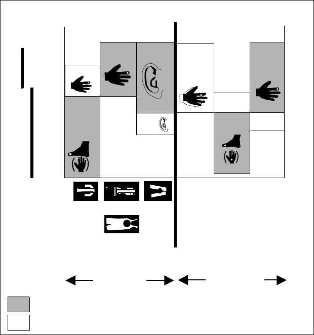
Draft - 1 Aug 08
Selecting a SpO2 Sensor
8-10 SpO2 Monitoring
To use the chart:
Find the patient’s weight on the vertical axes. On the horizontal axis at this
weight, the shaded areas indicate that the sensor is a “best choice” for the
patient. Unshaded areas indicate a “good choice.” For example, the best
reusable sensor for a 50 kg patient is the M1191A, applied to the finger or toe.
Alternatively, you could use M1194A applied to the ear. For a complete listing
of available sensors, see “SpO2 Accessories” on page A-6.
Selecting an SpO2 Sensor
Preferred sensor types
Alternative sensor types
Disposable
sensor
M1192A M1191B M1194A
Philips
M1901B
N-25
N
M1903B
D-20
P
M1904B
D-25
A
110
88
66
44
33
Pedi Adult
Patient
Weight
( kg )
50
40
30
20
15
Pedi
Adult Adult
Pedi
Adult
Patient
Weight
( lb )
Pedi
Pedi
Pedi
Adult
Oxisensor
OxiMax
M1196A
Reusable
sensor

Draft - 1 Aug 08
Applying the Sensor
SpO2 Monitoring 8-11
Applying the Sensor
Sensor
Application
Safety
Information
WarningWarning
Failure to apply a sensor properly can reduce the accuracy of the SpO2
measurement.
Loose/Tight sensor: If a sensor is too loose, it can compromise the optical
alignment or fall off. If it is too tight, for example because the application site is
too large or becomes too large due to edema, excessive pressure can be applied.
This can result in venous congestion distal from the application site, leading to
interstitial edema, hypoxia and tissue malnutrition. Skin irritations or
ulcerations can occur as a result of the sensor being attached to one location for
too long.
To avoid skin irritations and ulcerations, inspect the sensor application site
every 2-3 hours, and change the application site at least every 4 hours or
according to clinical practice guidelines.
Venous Pulsation: Do not apply sensor too tightly as this results in venous
pulsation, which can severely obstruct circulation and lead to inaccurate
measurements.
Ambient Temperature: Never apply an SpO2 sensor at ambient temperatures
above 37 oC (99 oF) because this can cause severe burns after prolonged
application.
Extremities to Avoid: Avoid sites distal to BP cuff, intra-arterial line, or
intravascular venous infusion line.
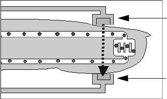
Draft - 1 Aug 08
Applying the Sensor
8-12 SpO2 Monitoring
Site
Selection • Avoid sites with impaired perfusion, skin discoloration, excessive motion
or nail polish.
• Avoid placing the sensor in an environment with bright lights (if
necessary, cover the sensor with opaque material).
• Avoid use of excessive pressure at the application site (e.g., sensor
applied too tightly, excessive adhesive tape to secure the sensor, clothing
or restraints that are too tight). These result in venous pulsations and
inaccurate measurement, and may severely obstruct circulation.
Sensor
Application A minimum pulsatile flow must be present at the application site of your patient
to obtain measurements.
Select an appropriate sensor and apply the sensor properly to avoid incorrect
measurements. Applying a small amount of pressure at the application site can
improve the measurement. Use one of the preferred application sites for your
sensor. Selecting the most suitable sensor and application site will help you to
ensure that:
• The light emitter and the photo detector are directly opposite each other
and that all the light from the emitter passes through the patient's tissues,
• The application site is of the correct thickness for light to pass through. If
the application site is too thick or too thin, an SpO2 NON-PULSATILE
technical alarm will occur. You should then select another site as
appropriate.
Positioning of the Light Emitter and Photo Detector
Light Emitter
Photo Detector
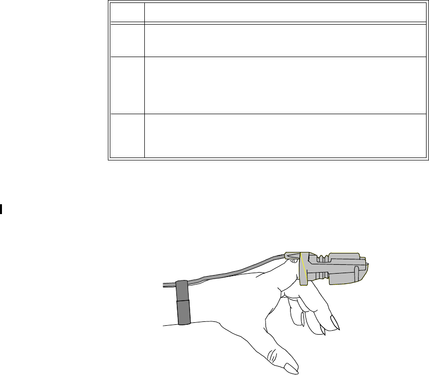
Draft - 1 Aug 08
Applying the Sensor
SpO2 Monitoring 8-13
Inspect the application site every 2 to 3 hours or according to clinical practice
guidelines to ensure skin integrity and correct optical alignment. If skin
integrity changes, move the sensor to another site.
Follow the sensor’s instructions for use, adhering to all warnings and cautions.
To apply the sensor, use the following directions.
Adult Finger
sensor
(M1191A/B)
Push the sensor over the fingertip in such a way that the fingertip touches but
does not protrude from the end of the sensor. The fingertip must be uppermost
and the cable must lie on the back of the hand. This ensures that the light source
cover the base of the fingertip giving the best measurement results. The cable
can be held in place by the accompanying wristband.
Step Action
1 Select the site and appropriate sensor (see “Selecting a SpO2
Sensor” on page 8-7).
2 Apply the sensor to the appropriate part of the patient’s body.
Note—The application site should match the sensor size so that the
sensor can neither fall off nor apply excessive pressure.
3 Check that the light emitter and the photo detector are directly
opposite each other. All light from the emitter must pass through the
patient’s tissue.
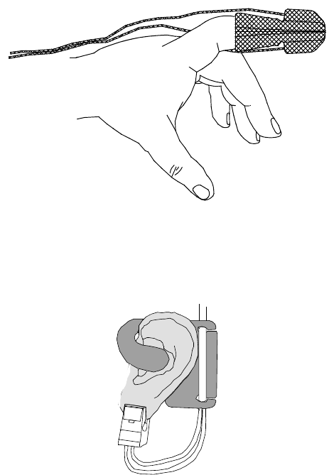
Draft - 1 Aug 08
Applying the Sensor
8-14 SpO2 Monitoring
Small Adult/
Pediatric
Finger sensor
(M1192A)
Push the sensor over the fingertip in such a way that the fingertip touches but
does not protrude from the end of the sensor.
Ear Clip sensor
(M1194A) Clip the probe onto the fleshy part of the ear lobe as shown in the diagram
below. The plastic fixing mechanism helps to minimize artifact generated by
patient motion. Do not position the probe on cartilage or where it presses
against the head.
The clip sensor can be used as an alternative if the adult finger sensor does not
provide satisfactory results. The preferred application site is the ear lobe,
although other application sites with higher perfusion (such as the nostril) can
be used. Due to the physiologically lower perfusion in the ear lobe, you should
be aware of the reduced accuracy of the measurement and more frequent
technical alarms.
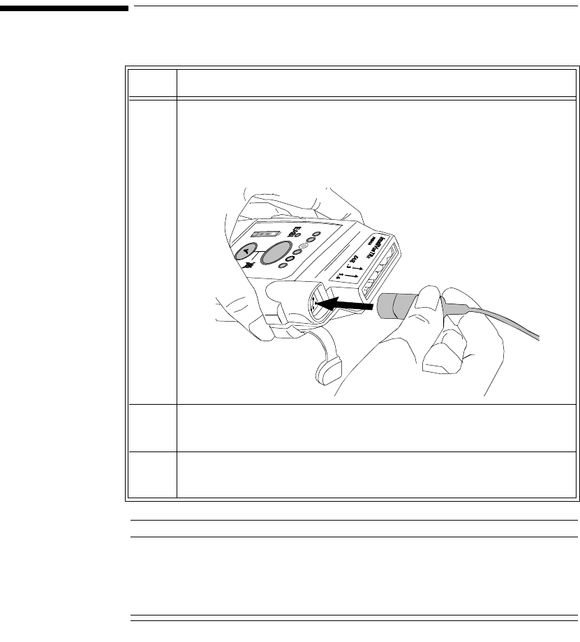
Draft - 1 Aug 08
Connecting the SpO2 Cable
SpO2 Monitoring 8-15
Connecting the SpO2 Cable
Caution
Extension cables: The use of extension cables presents a tripping hazard. Use
appropriate care when they are in use.
Electrical Interference: Position the sensor cable and connector away from
power cables, to avoid electrical interference.
Step Action
1 Connect the sensor cable to IntelliVue TRx+.
• Connect reusable sensors directly into the transceiver.
• Connect disposable sensors into the adapter cable, then
connect the adapter cable to the transceiver. Remove the
protective backing.
2 Adjust SpO2 alarms in the Patient Window (see “Telemetry
Controls in the Patient Window” on page 9-2).
3 Make other adjustments in the Telemetry Setup Window (see
“Patient Configurable Settings in Telemetry Setup” on page 9-6).

Draft - 1 Aug 08
Measuring SpO2
8-16 SpO2 Monitoring
Measuring SpO2
WarningWarning
Removal of the SpO2 sensor during Continuous SpO2 monitoring results in
a "No Sensor" technical alarm. There is no technical alarm for a “No
Sensor” condition in Spot Check mode.
WarningWarning
If you measure SpO2 on a limb that has an inflated NBP cuff, a non-
pulsatile SpO2 technical alarm can occur. If the monitor is configured to
suppress this alarm, there can be a delay of up to 60 seconds in indicating
critical patient status, such as sudden pulse loss or hypoxia.
SpO2 measurements can be made manually on an as-needed basis in Spot
Check mode, or continuously in Continuous mode, depending on the transceiver
configuration. While operating in Continuous mode, you can also measure
pulse, and display the pleth wave at the Information Center. The SpO2
parameter is turned on by inserting/removing the sensor cable into the
transceiver, or by control from the Information Center. SpO2 monitoring
consumes considerable electrical energy. The battery power must be at least
25% full in order to make SpO2 measurements.
Setting the mode to Spot Check or Continuous is done at the Information Center
(see “Patient Configurable Settings in Telemetry Setup” on page 9-6) or at the
monitor.

Draft - 1 Aug 08
Measuring SpO2
SpO2 Monitoring 8-17
Spot Check
Measurement When the transceiver is configured for Spot Check measurement, use the
following instructions to take an individual, manual SpO2 reading from the
transceiver.
Note—You can also initiate a Spot Check measurement in the Patient Window
at the Information Center by selecting the Spot Check SpO2 icon (see
“Patient Configurable Settings in Telemetry Setup” on page 9-6).
Note—Spot Check measurements cannot be made when the transceiver is
connected to TeleMon because only Continuous measurement is available with
this device.
Step Action
1 Attach the sensor to the patient.
2 Connect the SpO2 cable to IntelliVue TRx+, and check that:
•The SpO
2 sensor light turns on.
• A low-pitch tone detecting each pulse is audible (unless
sounds are muted).
3 After approximately 30 seconds, if the measurement was successful,
you’ll hear a single beep from the transceiver. The value, with the
measurement time, will be displayed at the Information Center. The
sensor light will extinguish.
If the measurement was unsuccessful, you’ll hear a double beep.
Remove the sensor cable and reinsert it to retake the measurement.
Note—The SpO2 value and time stamp remain on the Information
Center for 1 hour or until another measurement is taken, with one
exception: If the batteries are removed from the transceiver, the Spot
Check measurement will be erased from the display; however, the
SpO2 measurements will be available in Trend Review.
4To repeat a Spot Check measurement at the bedside, disconnect
then reconnect the SpO2 cable to the transceiver.

Draft - 1 Aug 08
Measuring SpO2
8-18 SpO2 Monitoring
Continuous
Measurement When the transceiver is configured for Continuous SpO2 measurement (see
“Patient Configurable Settings in Telemetry Setup” on page 9-6), use the
following directions to initiate Continuous SpO2 monitoring.
Displaying
Pulse Rate When operating in Continuous mode, you can view the Pulse rate at the
Information Center. See “Patient Configurable Settings in Telemetry Setup” on
page 9-6.
Note—If Pulse rate is turned on, the Patient Sector and Patient Window of the
Information Center display the parameter label with “T” (for example,
"PulseT") to indicate that the measurement was made via telemetry.
Displaying
Pleth Wave The transceiver can be configured to transmit the Pleth wave for display at the
Information Center. See “Patient Configurable Settings in Telemetry Setup” on
page 9-6.
Step Action
1 Insert the SpO2 cable into the IntelliVue TRx+, and check that the
sensor light turns on.
2 Attach the sensor to the patient.
3 After approximately 15 seconds, the value, with the measurement
time, is displayed at the Information Center.
Note—There are no sounds associated with continuous SpO2
measurement.
4 To discontinue SpO2 monitoring, uncheck the Enable SpO2 box at
the Information Center.
Note— If the sensor is removed without discontinuing SpO2
monitoring in the Telemetry Setup Window at the Information
Center, an SpO2T NO SENSOR technical alarm will result.
Silencing this technical alarm will turn the SpO2 measurement off.

Draft - 1 Aug 08
Measuring SpO2
SpO2 Monitoring 8-19
When
Connected
to TeleMon
When the transceiver is connected to TeleMon:
• The SpO2 measurement mode is always Continuous.
• You can change the mode. Changes to the mode take effect when the
transceiver is disconnected from TeleMon. The following settings will be
used:
Turning SpO2 Monitoring Off
To turn SpO2 monitoring off, disconnect the sensor cable from the transceiver.
SpO2 enters a power-down mode after the cable is disconnected from the
transceiver, thereby conserving battery life.
It is important to disconnect the sensor from the transceiver in order to conserve
battery life. Unplugging the sensor from an adapter cable that is connected to
the transceiver does NOT provide SpO2 power-down mode.
SpO2 should also be turned off at the Information Center. If the transceiver is
configured for Continuous SpO2 measurement and the sensor is removed
without turning SpO2 off, a SpO2T NO SENSOR technical alarm will result.
Silencing this technical alarm will turn the SpO2 measurement off.
Mode Set at TeleMon Mode when Transceiver
is Disconnected
Continuous Continuous
5-minute Continuous
1-minute Continuous
Manual Spot Check

Draft - 1 Aug 08
Understanding SpO2 Alarms
8-20 SpO2 Monitoring
SpO2
Enable/
Disable at
Information
Center
You can enable/disable SpO2 monitoring at the Information Center. See
“Patient Configurable Settings in Telemetry Setup” on page 9-6.
When SpO2 is enabled, the Patient Sector and Patient Window of the
Information Center display a “T” next to the SpO2 numeric (for example,
“SpO2T 90%”) to indicate that the measurement was made via telemetry.
SpO2 Auto
ON at
Information
Center
The SpO2 parameter is automatically enabled at the IntelliVue Information
Center if a manual SpO2 measurement is initiated at the transceiver while in
Spot Check mode or if the SpO2 sensor is inserted into the transceiver while the
transceiver is in Continuous SpO2 mode.
When a patient is discharged and the transceiver is in Continuous mode, the
SpO2 parameter is disabled. To reactivate the SpO2 parameter Auto ON feature
from the transceiver, remember to do one of the following when a patient is
discharged:
– remove the SpO2 cable from the transceiver, wait 15 seconds, then
reinsert the cable
or
– if using TeleMon, reset the transceiver to Manual mode.
Note—The SpO2 parameter Auto ON feature only needs to be reactivated when
the transceiver is in Continuous mode at discharge.
Note— SpO2 can always be enabled/disabled at the IntelliVue Information
Center.
Understanding SpO2 Alarms
Physiologic SpO2 alarms are generated and displayed at the Information Center.
SpO2 offers high and low limit alarms, and a high priority (red level) oxygen
desaturation alarm. The SpO2 low limit can be set between 50 and 99%
inclusive, in 1% increments. The desaturation limit is set automatically at 10

Draft - 1 Aug 08
Understanding SpO2 Alarms
SpO2 Monitoring 8-21
below the Low Limit. The SpO2 high alarm limit can be set between 51 and
100% inclusive, in 1% increments.
The delay between the physiologic alarm condition and alarm annunciation at
the Information Center is <16 seconds. This means that the Information Center
will generate an alarm if the averaged numeric value on the display exists
beyond the alarm limit for more than a maximum of 16 seconds.
Setting the high SpO2 alarm limit to 100% is equivalent to switching off the
high alarm. Therefore the upper alarm limit for oxygen saturation must be
carefully selected in accordance with accepted clinical practices.
The default setting for SpO2 yellow alarms is latched. That is, when an SpO2
limit is exceeded, you will need to acknowledge it at the Information Center.
The sound will be silenced but the message will remain on the display until the
condition is resolved.
See Chapter 5, “Alarms” for a list of the SpO2 alarms.

Draft - 1 Aug 08
Optimizing SpO2 Measurement Performance
8-22 SpO2 Monitoring
Optimizing SpO2 Measurement Performance
Refer to this section on problem situations if you have difficulty getting a signal
or obtaining accurate measurements.
Distortion
Ambient light, motion, perfusion or incorrect sensor placement can affect the
accuracy of the derived measurements.
Arterial Blood Flow
The measurement depends on the pulsatile nature of blood flow in the arteries
and arterioles; with the following conditions arterial blood flow can be reduced
to a level at which accurate measurements cannot be made:
•shock
• hypothermia
• use of vasoconstrictive drugs
• anemia
Wavelength Absorption
The measurement also depends on the absorption of particular light wavelengths
by the oxyhemoglobin and reduced hemoglobin. If other substances are present
which absorb the same wavelengths, they will cause a falsely high, or falsely
low SpO2 value to be measured. For example:
• carboxyhemoglobin
• methemoglobin
• methylene blue
• indocyanine green*
• indiocarmine*
*These chemicals are used in dye dilution cardiac output calculations.
Ambient Light
Very high levels of ambient light can also affect the measurement; an "SpO2
Interference" message will appear on the display. The measurement quality can
be improved by covering the sensor with suitable opaque material.
Draft - 1 Aug 08
Optimizing SpO2 Measurement Performance
SpO2 Monitoring 8-23
Care and Cleaning
For care and cleaning instructions, see the instructions accompanying the
sensors.
Sensor Wear
Normal wear and tear associated with patient movement and regular sensor
cleaning typically mean that the sensor will have a limited lifetime. However,
provided you handle the sensor and its cable with care, you can expect useful
service from it for up to two years. Harsh treatment will drastically reduce the
lifetime of the sensor. Moreover, Philips Medical Systems’ warranty agreement
shall not apply to defects arising from improper use.
To get the best results from your SpO2 reusable sensor:
• Always handle the sensor and cable with care. The soft finger sleeve
houses a sensitive electronic device that can be damaged by harsh
treatment. Always protect the cable from sharp-edged objects.
• Use the wristband that is supplied with your M1191A sensor. By keeping
the cable between the finger sensor and the wristband fairly loose, you
will maintain good monitoring conditions.
Draft - 1 Aug 08
Optimizing SpO2 Measurement Performance
8-24 SpO2 Monitoring
Draft - 1 Aug 08
Telemetry Functions at the Information Center & TeleMon 9-1
Introduction
9
Telemetry Functions at the
Information Center & TeleMon
This chapter describes the telemetry functions at the Information Center and
IntelliVue Patient Monitor, as well as the differences in transceiver operation
when connected to TeleMon. It includes the sections listed below. For
additional information, consult the IntelliVue Information Center Instructions
for Use and TeleMon Instructions for Use.
• Telemetry Functions at the Information Center . . . . . . . . . . . . . . . . . . 9-2
•Telemetry Controls in the Patient Window . . . . . . . . . . . . . . . . . . 9-2
•Locating the Transceiver (Find Device). . . . . . . . . . . . . . . . . . . . . 9-3
•Patient Configurable Settings in Telemetry Setup . . . . . . . . . . . . . 9-6
•Unit-Configurable Settings . . . . . . . . . . . . . . . . . . . . . . . . . . . . . . 9-9
• Transceiver Operation when Connected to TeleMon. . . . . . . . . . . . . 9-19

Draft - 1 Aug 08
Telemetry Functions at the Information Center
9-2 Telemetry Functions at the Information Center & TeleMon
Telemetry Functions at the Information Center1
Telemetry
Controls in
the Patient
Window
The Patient Window at the Information Center (accessed from the Patient
Window control in the Patient Sector) includes controls for a number of
telemetry operations. For detailed instructions on these operations, see the
IntelliVue Information Center Instructions for Use or the Online Help.
To View ECG or SpO2 Alarm Limits
Move the cursor over the HR or SpO2 label to display the current high and low
alarm limits.
To Change ECG or SpO2 Alarm Limits
Move the cursor over the High or Low numeric to display up/down arrow
controls for adjusting the limit. After adjusting the limit, move the cursor away
from the area to dismiss the limit controls.
To Change ECG Waveform Size
Move the cursor over the ECG waveform to display the ECG Waveform Size
control. Select the desired size from the list.
To Select Lead
Move the cursor over the ECG waveform to display the Lead Selection control.
Select the desired lead from the list.
Important—Do not set the primary and secondary channels to the same lead.
To Change Va and Vb Default Lead Settings (6-lead only)
Move the cursor over the ECG waveform to display the Lead Selection popup.
Select the label from the label list. For Va or Vb, select Va or Vb, then select the
lead to be assigned. Assignment of the same V lead to both Va and Vb is not
allowed.
Important—Do not set the primary and secondary channels to the same lead.
1. For information on ST functions performed at the Information Center, see “ST/AR ST
Segment Algorithm” on page 7-7.
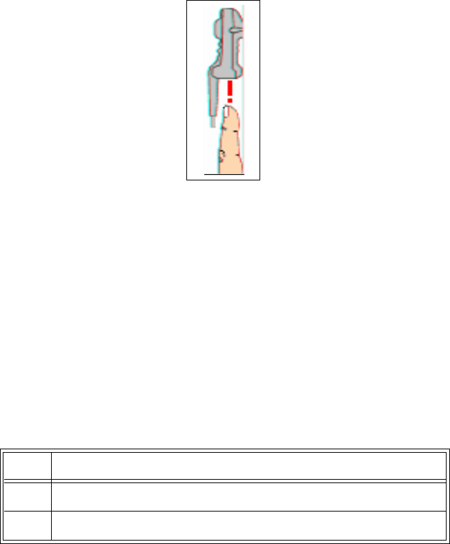
Draft - 1 Aug 08
Telemetry Functions at the Information Center
Telemetry Functions at the Information Center & TeleMon 9-3
To Initiate a Spot Check Measurement
Move the cursor over the SpO2 label. Then click on the Spot Check icon.
.
Note—There is no audio feedback at the transceiver (pulse tone or successful/
failed measurement) when Spot Check is initiated at the Information Center.
To Initiate Standby
See instructions under “Standby Mode” on page 4-4.
Locating the
Transceiver
(Find
Device)
The Find Device feature enables you to generate an alternating pitch repeated
tone at the transceiver to assist in locating a missing device. This function is
initiated in the Telemetry Setup Window. Find Device requires that the
transceiver has good working batteries and is within the coverage area. The
device will not return from out-of-range until association with the Information
Center is re-established.
To locate a
transceiver Step Action
1 From the Patient Window, select Telemetry Setup.
2 Select Find Device to generate a repeated tone at the transceiver.

Draft - 1 Aug 08
Telemetry Functions at the Information Center
9-4 Telemetry Functions at the Information Center & TeleMon
To silence the
sound
Viewing
Device
Location in
the Patient
Window
(optional)
You can see the location of a transceiver in the Patient Window. The Device
Location information is identified in the Patient Window by a compass icon
followed by the location name configured by your hospital for your system. If
the location of the transceiver changes, the Patient Window is updated within 5
seconds of the location change.
Viewing
Device
Location
History
(optional)
You can view the location history for a particular transceiver in the Device
Location History field in the Telemetry Setup window. The field displays the
five most recent Device Location descriptions in ascending order and updates
every time there is a change in location for the device. The total timespan of the
log is 60 minutes.
Note—If there is a change in location while viewing the Telemetry Setup
window, you must re-enter Telemetry Setup to see the change, as it does not
update automatically.
Step Action
1 Press and hold the Check button to turn off the sound.
OR
Remove the batteries.

Draft - 1 Aug 08
Telemetry Functions at the Information Center
Telemetry Functions at the Information Center & TeleMon 9-5
Using the
Device
Location
Client
(optional)
The Device Location Client application is an optional software application that
allows you to display and locate devices visually, using Floor Plans associated
with your hospital’s layout. Device location history is also available. The
application is accessible using a seperate PC’s web browser. For additional
installation information, see the IntelliVue Device Location Installation Guide.
WarningWarning
Because the coverage range of Access Points can sometimes overlap,
including different floor levels, the IntelliVue Device Location feature is not
intended for use when attempting to locate a patient.
Displaying and
Locating
Devices
The left side of the Client display screen contains a list of clinical units
associated with the current Floor Plan. Each unit contains a list of bed labels.
You view the beds listed within a unit by clicking on the plus sign next to the
unit name.
Note—The beds listed are only those equipped with IntelliVue telemetry
devices.
To identify and locate the telemetry device associated with the bed, simply click
on the desired bed label. The floor plan and the status bar above the floor plan
image now display the location of the device. Additionally, the status bar lists
the Access Point the device is currently associated with.
Viewing Device
Location
History
The location history of a particular telemetry device is also available. Select a
device from the Device List box and then click on the down arrow in the status
bar. The last five known locations of the device are displayed.

Draft - 1 Aug 08
Telemetry Functions at the Information Center
9-6 Telemetry Functions at the Information Center & TeleMon
Patient
Configurable
Settings in
Telemetry
Setup
The Telemetry Setup window enables you to configure the transceiver for
patient-specific settings. All patient-specific settings will be reset to the unit
defaults upon patient discharge. To access the window, from the Patient
Window click Telemetry Setup.
The following settings can be adjusted in this window.
Patient-Configurable Settings in Telemetry Setup
Control Function Setting Choices Factory
Default
Telemetry
Button Determine the Information Center
response when Telemetry Button
is pressed.
Nurse Call - generate nurse
call alarm
Record - generate a
recording strip
Nurse Call and Record -
generate nurse call alarm and
recording strip
None
Nurse Call
Telemetry
Device:
Volume
Set the volume level for all
adjustable sounds on the
transceiver.
1 (low), 2, 3, 4, 5 (high) 3
Telemetry
Device:
Mute
Enable/disable Spot Check and
pulse detection tones on the
transceiver.
enable (mute)
disable
enable
Fixed Pacer
Amplitude Sets the appearance of the pacer
spikes to a fixed size as they
appear in the patient window.
enable
disable
disable

Draft - 1 Aug 08
Telemetry Functions at the Information Center
Telemetry Functions at the Information Center & TeleMon 9-7
SpO2
Enabled Enable/disable the SpO2
measurement at the Information
Center or Telemon.
enable
disable
enable
SpO2 Mode Determine the transceiver SpO2
behavior.
Note—Pulse Rate and Pleth Wave
are not available in Spot Check.
Spot Check - Provides
manual measurements so the
clinician can check as
needed. Measurement
initiated by plugging the
SpO2 cable into the
transceiver or by selecting
the Spot Check SpO2 icon in
the Patient Window. No
pulse or successful/failed
measurement tones are
generated when
measurement is initiated at
Information Center.
Continuous - Sends an SpO2
parameter value to the
Information Center every
second. If selected, Pulse
Rate and Pleth Wave may
also be sent.
Spot Check
Patient-Configurable Settings in Telemetry Setup
Control Function Setting Choices Factory
Default

Draft - 1 Aug 08
Telemetry Functions at the Information Center
9-8 Telemetry Functions at the Information Center & TeleMon
Suppress
SpO2 INOPs
with NBP
Enable/disable the SpO2
algorithm to suppress sending
technical alarms from the
transceiver during an NBP
measurement for 60 seconds.
WarningWarning
If you measure SpO2 on a limb
that has an inflated NBP cuff, a
non-pulsatile SpO2 technical
alarm can occur. If the monitor
is configured to suppress this
alarm, there can be a delay of
up to 60 seconds in indicating
critical patient status, such as
sudden pulse loss or hypoxia.
enable
disable
enable
Pleth Wave Enable/disable the transmission
of the Pleth wave (and its
subsequent display) to the
Information Center. For
Continuous SpO2 mode only.
Note—When enabled, the Pleth
wave replaces the Vb wave in the
Patient Window during 6-lead
monitoring.
enable
disable
disable
(Pleth is not
displayed.)
Pulse Enable/disable display of the
Pulse rate at the Information
Center. For Continuous SpO2
mode only.
enable
disable
disable
(Pulse rate is
not
displayed.)
Patient-Configurable Settings in Telemetry Setup
Control Function Setting Choices Factory
Default

Draft - 1 Aug 08
Telemetry Functions at the Information Center
Telemetry Functions at the Information Center & TeleMon 9-9
Unit-
Configurable
Settings
Unit Settings provide access to clinical configuration items that affect all
patients on an Information Center. Changes in unit settings take effect upon
discharge, except for Standby duration and SpO2 mode, which take effect
immediately.
Access to unit settings requires a password, and the displays are in English.
Telemetry specific settings are accessed through All Controls -> Unit Settings
-> Telemetry Setup. The setting for telemetry non-arrhythmia yellow alarms
is located in All Controls -> Unit Settings -> Alarms Unit Settings. For all
other information on unit settings, see IntelliVue Information Center
Instructions for Use.
SpO2 Alarm Turn SpO2 alarms on/off at the
Information Center. enable (on)
disable (off)
enable
Unit Settings Change current settings back to
last saved clinical unit settings. (none)
Patient-Configurable Settings in Telemetry Setup
Control Function Setting Choices Factory
Default
Unit Settings - Telemetry Setup
Control Function Settings Factory
Default
Patient Type Set patient type used for SpO2
and NBP alarm limits. Adult
Pediatric
Adult

Draft - 1 Aug 08
Telemetry Functions at the Information Center
9-10 Telemetry Functions at the Information Center & TeleMon
Telemetry
Button Determine the Information
Center response when Telemetry
Button is pressed.
Nurse Call - generate nurse
call alarm
Record - generate a recording
strip
Both - generate nurse call
alarm and recording strip
None
Nurse Call
Telemetry
Device:
Volume
Set the volume level for all
adjustable sounds on the
transceiver.
1 (low) to 5 (high) 3
Telemetry
Device:
Mute
Enable/disable all adjustable
sounds on the transceiver. enable (unchecked) = sound
disable (checked) = mute
mute
Standby
Duration Sets the standby duration on the
device. Infinite
10 minutes
20 minutes
30 minutes
1 hour
2 hours
3 hours
4 hours
Infinite
Enable
Remote
Suspend
Enable/disable alarm pause/
suspend at the transceiver. enable
disable
disable
Unit Settings - Telemetry Setup
Control Function Settings Factory
Default

Draft - 1 Aug 08
Telemetry Functions at the Information Center
Telemetry Functions at the Information Center & TeleMon 9-11
Suspend
Duration Sets the alarm suspend duration
time for each assigned device on
the Information Center.
1, 2, or 3 minutes 2 minutes
Battery
Gauge on
Information
Center
Display/disable a battery gauge
for each assigned device on the
Information Center.
Note—Set to disable if
rechargeable batteries are being
used.
enable
disable
enable
(battery
gauge is
displayed)
RF Auto
Shutoff Enable/disable RF operation
during an extended situation of
all leads off for more than 10
minutes and the SpO2 sensor is
not connected.
enable
disable
enable
Fixed Pacer
Amplitude Sets the appearance of the pacer
spikes to a fixed size as they
appear in the patient window.
enable
disable
disable
Autopair Enable/disable the autopairing of
the transceiver and the
IntelliVue Patient Monitor at the
Information Center.
enable
disable
enable
Enable SpO2 Enable/disable the SpO2
measurement at the Information
Center or Telemon.
enable
disable
enable
Unit Settings - Telemetry Setup
Control Function Settings Factory
Default

Draft - 1 Aug 08
Telemetry Functions at the Information Center
9-12 Telemetry Functions at the Information Center & TeleMon
SpO2 Mode Determine the transceiver SpO2
behavior.
Note—Pulse Rate and Pleth
Wave are not available in Spot
Check.
Spot Check - Provides
manual measurements so the
clinician can check as
needed. Measurement
initiated by plugging the
SpO2 cable into the
transceiver or by selecting
Spot Check SpO2 icon in the
Patient Window. No pulse or
successful/failed
measurement tones are
generated when measurement
is initiated at Information
Center.
Continuous - Sends an SpO2
parameter value to the
Information Center every
second. If selected, Pulse
Rate and Pleth Wave may
also be sent.
Spot Check
Unit Settings - Telemetry Setup
Control Function Settings Factory
Default

Draft - 1 Aug 08
Telemetry Functions at the Information Center
Telemetry Functions at the Information Center & TeleMon 9-13
Suppress
SpO2 Inops
with NBP
Enable/disable the SpO2
algorithm to detect NBP running
and suppress sending technical
alarms from the transceiver for
60 seconds.
WarningWarning
If you measure SpO2 on a limb
that has an inflated NBP cuff,
a non-pulsatile SpO2 technical
alarm can occur. If the
monitor is configured to
suppress this alarm, there can
be a delay of up to 60 seconds
in indicating critical patient
status, such as sudden pulse
loss or hypoxia.
enable
disable
enable
Pleth Wave Enable/disable the transmission
of the Pleth wave and its
subsequent display to the
Information Center. For
Continuous mode only.
enable
disable
Note—When enabled, during
6-lead monitoring, the Pleth
wave will replace the Vb
wave in the Patient Window.
disable
(Pleth wave
is not
displayed.)
Pulse Enable/disable the transmission
of the Pulse rate and its
subsequent display to the
Information Center. For
Continuous mode only.
enable
disable
disable
(Pulse rate is
not
displayed.)
Unit Settings - Telemetry Setup
Control Function Settings Factory
Default

Draft - 1 Aug 08
Telemetry Functions at the Information Center
9-14 Telemetry Functions at the Information Center & TeleMon
SpO2 Alarm Turn SpO2 alarms on/off at the
Information Center. enable (on)
disable (off)
enable
SpO2 Limits
High Increment/decrement SpO2 high
alarm limit by 1 (in %). Limit maximum is 100. Limit
minimum is 51 (adult) or 31
(pediatric). High and low
limit must be at least 1%
apart.
100 (adult,
pediatric)
SpO2 Limits
Low Increment/decrement SpO2 low
alarm limit by 1 (in %). Limit maximum is 99. Limit
minimum is 50 (adult) or 30
(pediatric). High and low
limit must be at least 1%
apart.
90 (adult,
pediatric)
Unit Settings - Telemetry Setup
Control Function Settings Factory
Default
Unit Settings - Default Leads
Control Function Settings Factory
Default
Leadset
Allowed Set the unit default leadset type. All, EASI, No EASI, 3 wire All
3-wire Set the unit default lead. I, II, III II
5-wire, ECG1 Set the unit default lead. I, II, III, MCL, AVR, AVL,
AVF, VII
5-wire, ECG2 Set the unit default lead. I, II, III, MCL, AVR, AVL,
AVF, VV

Draft - 1 Aug 08
Telemetry Functions at the Information Center
Telemetry Functions at the Information Center & TeleMon 9-15
5-wire, ECG3 Set the unit default lead. I, II, III, MCL, AVR, AVL,
AVF, VIII
5-wire EASI,
ECG1 Set the unit default lead. I, II, III, AVR, AVL, AVF, V1,
V2, V3, V4, V5, V6
II
5-wire EASI,
ECG2 Set the unit default lead. I, II, III, AVR, AVL, AVF, V1,
V2, V3, V4, V5, V6
V2
5-wire EASI,
ECG3 Set the unit default lead. I, II, III, AVR, AVL, AVF, V1,
V2, V3, V4, V5, V6
III
5-wire EASI,
ECG4 Set the unit default lead. I, II, III, AVR, AVL, AVF, V1,
V2, V3, V4, V5, V6
V5
6-wire, ECG1 Set the unit default lead. I, II, III, MCL, AVR, AVL,
AVF, V1, V2, V3, V4, V5, V6,
V7, V8, V9, V3R, V4R, V5R
II
6-wire, ECG2 Set the unit default lead. I, II, III, MCL, AVR, AVL,
AVF, V1, V2, V3, V4, V5, V6,
V7, V8, V9, V3R, V4R, V5R
V2; V lead
choice is
determined
by Va and
Vb settings
6-wire, ECG3 Set the unit default lead. I, II, III, MCL, AVR, AVL,
AVF, V1, V2, V3, V4, V5, V6,
V7, V8, V9, V3R, V4R, V5R
III
Unit Settings - Default Leads
Control Function Settings Factory
Default

Draft - 1 Aug 08
Telemetry Functions at the Information Center
9-16 Telemetry Functions at the Information Center & TeleMon
6-wire, ECG4 Set the unit default lead. I, II, III, MCL, AVR, AVL,
AVF, V1, V2, V3, V4, V5, V6,
V7, V8, V9, V3R, V4R, V5R
V5; V lead
choice is
determined
by Va and
Vb settings
Unit Settings - Default Leads
Control Function Settings Factory
Default
Unit Settings - NBP Setup
Control Function Settings Factory
Default
Patient Type Set patient type used for NBP
alarm limits. Adult
Pediatric
Adult
NBP Alarm Set NBP alarm notification. Systolic or Diastolic
Systolic
Diastolic
Mean
Off
Systolic or
Diastolic
Systolic High Increment/decrement NBP high
alarm limit by 1. Limit Maximum is 260
Limit Minimum is 160 (Adult)
Limit Maximum is 260
Limit Minimum is 75 (Ped.)
160 Adult
120 Pediatric

Draft - 1 Aug 08
Telemetry Functions at the Information Center
Telemetry Functions at the Information Center & TeleMon 9-17
Systolic Low Increment/decrement NBP low
alarm limit by 1. Limit Maximum is 155
Limit Minimum is 28 (Adult)
Limit Maximum is 255
Limit Minimum is 28 (Ped.)
90 Adult
70 Pediatric
Diastolic
High Increment/decrement NBP high
alarm limit by 1. Limit Maximum is 260
Limit Minimum is 90 (Adult)
Limit Maximum is 260
Limit Minimum is 45 (Ped.)
90 Adult
70 Pediatric
Diastolic Low Increment/decrement NBP high
alarm limit by 1. Limit Maximum is 85
Limit Minimum is 28 (Adult)
Limit Maximum is 40
Limit Minimum is 28 (Ped.)
50 Adult
40 Pediatric
Mean High Increment/decrement NBP high
alarm limit by 1. Limit Maximum is 260
Limit Minimum is 65 (Adult)
Limit Maximum is 260
Limit Minimum is 55 (Ped.)
110 Adult
90 Pediatric
Mean Low Increment/decrement NBP high
alarm limit by 1. Limit Maximum is 60
Limit Minimum is 28 (Adult)
Limit Maximum is 50
Limit Minimum is 28 (Ped.)
60 Adult
50 Pediatric
Unit Settings - NBP Setup
Control Function Settings Factory
Default

Draft - 1 Aug 08
Telemetry Functions at the Information Center
9-18 Telemetry Functions at the Information Center & TeleMon
RF Auto
Shutoff When RF Auto Shutoff is enabled (default), the transceiver stops broadcasting a
radio signal in order to prevent interference with other transceivers in use. This
condition occurs if there is no ECG signal for 10 minutes and the SpO2 sensor
cable is not inserted in the SpO2 sensor port. The technical alarm, "No Signal",
followed by the "Transmitter Off" INOP will be displayed at the Information
Center. Remove the batteries to conserve battery charge. However, if there is no
ECG signal for 10 minutes but the SpO2 cable is inserted, the transceiver does
not stop broadcasting the signal. This feature can be disabled in Unit Settings.
Unit Settings - Alarms
Control Function Settings Factory
Default
Non-
arrhythmia
Yellow
Alarms
Set latched/non-latched status
for SpO2, ST, and other non-
arrhythmia yellow alarms.
Latched
Non-latched
Latched
Leads Off Adjust the severity level of this
technical alarm (INOP). Cyan
Yellolw
Red
Cyan
Replace
Battery Adjust the severity level of this
technical alarm (INOP). Cyan
Yellow
Red
Cyan

Draft - 1 Aug 08
Transceiver Operation when Connected to TeleMon
Telemetry Functions at the Information Center & TeleMon 9-19
Transceiver Operation when Connected to TeleMon
When connected to TeleMon, the following differences in transceiver operation
will be in effect.
Important—The transceiver must have good batteries installed before being
connected to TeleMon.
Alarms
• Alarm Suspend/Pause and Standby can be initiated only from TeleMon,
not from the transceiver or the Information Center. The alarm suspend
indicator on the transceiver will accurately reflect the current state of
alarm pause.
Note—If the transceiver is connected to TeleMon, silencing an active alarm at
TeleMon silences the alarm at TeleMon only. It has no effect on the alarms at
the Information Center.
ECG Operation
• Vb, the second V-lead in 6-wire lead-set, is not supported.
• After a change in leadset, the TeleMon returns to the default ECG
settings, and arrhythmia relearn occurs automatically. Be sure to check the
monitoring leads after you switch leadsets. See “Relearning” on page 6-
28.

Draft - 1 Aug 08
Transceiver Operation when Connected to TeleMon
9-20 Telemetry Functions at the Information Center & TeleMon
SpO2 Operation
•SpO
2 is always in continuous mode.
• Changes in SpO2 mode do not take effect until after the transceiver is
disconnected from TeleMon. Mode settings are defined in the following
table:
• If the sensor is disconnected from the transceiver during SpO2 monitoring
at TeleMon, a No Sensor technical alarm will be displayed at the
Information Center. Visual and auditory indicators for the No Sensor
Alarm are not active at Telemon.
Battery
• The transceiver battery status is not available. When the Check button is
pressed, the battery gauge on the transceiver and at the Information Center
indicates full power, regardless of actual battery strength.
Defibrillation
• In the event of patient defibrillation, it may take several seconds for the
ECG trace to reappear on the screen.
Telemetry Overview
• If NBP is being monitored, NBP values will be displayed at the Overview
window.
Mode Selected at TeleMon Mode at Disconnected Transceiver
Continuous Continuous
5-min. Continuous
1-min. Continuous
Manual Spot Check

Draft - 1 Aug 08
Pairing Monitoring Devices 10-1
Introduction
10
Pairing Monitoring Devices
You can display measurement data from IntelliVue TRx and TRx+ Transceivers
on IntelliVue Patient Monitors. The transceiver and the monitor must be
assigned to the same patient; this is called "pairing". Once paired, the ECG
source is automatically detected at the Information Center. Should you
subsequently switch the ECG source between the two devices, the change is also
automatically detected at the Information Center.
Networked devices and non-networked devices can be paired, however, there
are differences in device behavior based on network connection status. Devices
can be connected and/or paired via the methods below:
• The transceiver is paired with the monitor at the Information Center
(networked devices only).
• The transceiver is directly connected to the monitor using an interface
cable (IntelliVue MP5/MP5T Patient Monitor only).
• The transceiver is directly connected to a non-networked monitor using an
interface cable to transmit additional parameters (IntelliVue MP5/MP5T
Patient Monitor only).
• The transceiver and monitor are connected wirelessly via short-range
radio capability (IntelliVue MP5/MP5T, MP2 and X2 Patient Monitors
only).
• The transceiver is connected wirelessly via short-range radio capability to
an MP5 or X2 Patient Monitor which is connected to a larger host
monitor.

Draft - 1 Aug 08
10-2 Pairing Monitoring Devices
This chapter describes how to pair the devices using a direct connection and a
wireless, short-range radio connection, and how the devices operate in paired
mode (networked and non-networked). It includes the sections listed below.
For additional information on monitor operation, consult the IntelliVue Patient
Monitor Instructions for Use. For additional information on pairing other
IntelliVue Patient Monitors at the Information Center, consult the IntelliVue
Information Center Instructions for Use.
• Pairing Networked Devices. . . . . . . . . . . . . . . . . . . . . . . . . . . . . . . . .10-3
• Alarm Behavior (Networked) . . . . . . . . . . . . . . . . . . . . . . . . . . . . . . .10-8
• Alarm Behavior (Networked with Cable or Short-Range Radio
Connection) . . . . . . . . . . . . . . . . . . . . . . . . . . . . . . . . . . . . . . . . . . . .10-12
• Paired Device Synchronized Alarm Settings (Networked). . . . . . . .10-14
• Pairing Non-networked Devices . . . . . . . . . . . . . . . . . . . . . . . . . . . .10-16
• Alarm Behavior (Non-networked) . . . . . . . . . . . . . . . . . . . . . . . . . .10-19
• More Bed Alarms . . . . . . . . . . . . . . . . . . . . . . . . . . . . . . . . . . . . . . .10-21
WarningWarning
Pairing of TRx4841/51A IntelliVue Telemetry Transceivers with IntelliVue
Patient Monitors operating via a short-range radio connection is only
supported when both the transceiver and the patient monitor are equipped
with short-range radio capability.
Note—Pairing of transceivers and IntelliVue Patient Monitors is not available
with IntelliVue Patient Monitors connected to the M3140 Information Center.
Note—The MP5T IntelliVue Patient Monitor is a non- networked device as it
does not support a connection to the Information Center.

Draft - 1 Aug 08
Pairing Networked Devices
Pairing Monitoring Devices 10-3
Device
Revision
Pairing
Functionality
The level of pairing functionality available is dependent on the software
revision of the devices in use. Refer to the following table to identify available
functionality.
Pairing Networked Devices
Pairing at the
Information
Center
You can pair an IntelliVue Patient Monitor with the transceiver at the
Information Center. The telemetry data automatically displays as a permanent
overview session in the Telemetry Data Window on the IntelliVue Patient
Monitor. At the Information Center, the telemetry data and any patient
monitor data (e.g. NBP) are integrated in the patient sector.
See your IntelliVue Information Center Instructions for Use or IntelliVue
Patient Monitor Instructions for Use for information on how to pair/unpair
devices.
Functionality Transceiver
Rev. Patient
Monitor Rev. Information
Center Rev.
Basic Pairing A.00 B.1 F.00
Pairing via Direct
Connection B.00 E.00 J.00
Enhanced Pairing
via Direct
Connection
B.01 F.00 K.00
Pairing via Short-
Range Radio
Connection
C.00 G.00 L.00

Draft - 1 Aug 08
Pairing Networked Devices
10-4 Pairing Monitoring Devices
Pairing with
a Direct
Connection
to the MP5
When the transceiver, assigned to a patient sector at the Information Center, uses
an interface cable to connect to an MP5 Patient Monitor, the Information Center
automatically pairs (if configured to do so) the two devices. Pairing using this
method provides up to 4 ECG waves at the MP5, along with SpO2
measurements and a pleth wave. Lead selection and alarm limits may be
changed either at the Information Center or the MP5 Patient Monitor.
To connect the transceiver to the monitor, perform the following steps:
WarningWarning
When the transceiver is directly connected to the monitor, arrhythmia
relearning is initiated, and again when the transceiver is disconnected from
the monitor. During relearn, a short dropout period may occur. Be sure to
check your patient’s arrhythmia annotation for accuracy whenever relearn
has occurred.
Controls on the transceiver (e.g. nurse call) will be inactive when the device
is directly connected to the monitor except in the case when the monitor has
no network connection and data are transferred via the transceiver.
Step Action
1 Remove the protective cover from the transceiver’s monitor/service
port.
2 Insert the interface cable into the monitor/service port.
3 Attach the interface cable to the monitor using the port labeled with
the icon.

Draft - 1 Aug 08
Pairing Networked Devices
Pairing Monitoring Devices 10-5
Important—When transceivers and MP5 Patient Monitors are paired directly via
an interface cable, your ECG source must be connected before connecting or
disconnecting the interface cable to maintain synchronized alarm settings. The
interface cable must be disconnected prior to unpairing the devices at the
Information Center or the monitor.
Pairing at
the
IntelliVue
Patient
Monitor
At the bedside you can pair a transceiver (including MP5/X2 IntelliVue Patient
Monitors with telemetry labels) with an IntelliVue Patient Monitor by either
directly connecting the devices with an interface cable as described on page
10-3, by pairing the devices through the Setup Telemetry menu on the IntelliVue
Patient Monitor, or if equipped to do so, via short-range radio capability. For
information on the Setup Telementry menu, see your IntelliVue Patient Monitor
Instructions for Use.
When the transceiver and monitor (MP5, MP2 or X2 only) are both equipped
with short-range radio capability, the transceiver can be paired with the monitor
at the monitor. Monitors which have this capability have a short range radio
symbol on the model label.
If your transceiver is not already equipped with the SRRA, follow the
instructions and figures below to install the adapter.

Draft - 1 Aug 08
Pairing Networked Devices
10-6 Pairing Monitoring Devices
Step Action
1 Remove the protective cover from the transceiver’s monitor/service
port.
2 Position the rubber cover over the top of the SRRA. Attach the
connected strap around the transceiver above the Leadset Insertion
Guide.
3 Insert the SRRA connector in the monitor/service port.

Draft - 1 Aug 08
Pairing Networked Devices
Pairing Monitoring Devices 10-7
To pair the transceiver to the monitor:
1. Press the Check Button on the transceiver. The measurement selection key
on the monitor will change to show the "assign telemetry" icon .
2. Select the assing telemetry icon.
3. In the Assign Telemetry Device menu, select the correct equipment label
for the device.
When connected, the icon appears at the Information Center.
The transceiver is assigned to the monitor. A "Tele Device Assigned" message
appears on the monitor, a tone sounds at the transceiver and its Leads Off
indicators light to indicate the successful assignment. If the ECG wave now
appears on the monitor, the signal from the transceiver is successfully
transmitting to the monitor. To confirm that the correct transceiver has been
assigned, open the ECG Setup menu by touching the ECG waveform or HR
numeric. The title of the menu contains the equipment label of the transceiver.
Check that this is the correct label.
If a monitor is already paired to another device, you cannot assign a transceiver
to that monitor.
If the transceiver goes out-of-range or loses the short-range radio connection, it
will switch over to standard telemetry transmission to the Information Center. In
this case, the telemetry data is displayed in the Telemetry Data Window.
If the devices are unpaired, the short-range radio connection is ended.
Unpairing
the Monitor
and
Transceiver
If the patient will no longer be monitored with the transceiver, or only with the
transceiver and no longer with the monitor, you need to end the device pairing.
After unpairing, the Information Center will receive data exclusively from the
monitor or from the transceiver:
• select the Unpair To Mon. SmartKey to end pairing and have
the Information Center receive the measurement data from the monitor
• select the Unpair To Tele SmartKey to end pairing and have
the Information Center receive the measurement data from the transceiver
or
• use the Unpair function at the Information Center.

Draft - 1 Aug 08
Pairing Networked Devices
10-8 Pairing Monitoring Devices
Note—The Unpair SmartKeys and pop-up keys appear only on the monitor
which is directly involved in pairing.
Alarm
Behavior
(Networked)
Both the IntelliVue Telemetry System and the IntelliVue Patient Monitor
source alarms. The following table summarizes alarm behavior when a
transceiver is paired with an IntelliVue bedside monitor without a direct cable
or short-range radio connection. For detailed information, see the IntelliVue
Patient Monitor Instructions for Use and the IntelliVue Information Center
Instructions for Use.
Note—This table assumes the two devices are paired without a cable
connection or short-range radio connection. When paired with a cable
connection or short-range radio connection, controls work in the same manner
as a single bedside monitor.
WarningWarning
For MP5 monitors, all data presented in the telemetry data window is
delayed for several seconds. If you need realtime data, for example, for
defibrillation, always use the monitor ECG. As long as the ECG is being
measured with the transceiver, there will be no ECG signal available at
the ECG analog output or ECG Sync Pulse output.
Note: MP5T bedside monitors do not have an ECG connection.

Draft - 1 Aug 08
Pairing Networked Devices
Pairing Monitoring Devices 10-9
Where Initiated Effect at Bedside Effect at Information Center
Silence
Bedside Silences bedside alarms.
Silences telemetry alarms if Enable
Global Silence for Paired Beds is on at
the Information Center.
Silences bedside alarms.
Silences telemetry alarms if Enable
Global Silence for Paired Beds is on
at the Information Center.
Bedside from
Telemetry Data
Window
Silences bedside and telemetry alarms.
Silence Overview Alarms at Bedside
must be enabled at the Information
Center.
Silences bedside and telemetry
alarms.
Silence Overview Alarms at Bedside
must be enabled at the Information
Center.
Information Center Silences bedside and telemetry alarms. Silences bedside and telemetry
alarms.

Draft - 1 Aug 08
Pairing Networked Devices
10-10 Pairing Monitoring Devices
Suspend/Pause
Bedside Suspends/Pauses bedside alarms. Bed Alarms Suspend/Bed Alarms
Paused INOP displayed.
Information Center Suspends/Pauses bedside and
telemetry alarms. Suspends/Pauses bedside and
telemetry alarms. Alarms Suspend/
Alarms Paused INOP displayed. All
Arrh Alrms OFF displayed.
Note—Suspends bedside alarms for
the minimum of the transceiver
configuration and the bedside
configuration.
Transceiver
(Remote Suspend
enabled at the
Information
Center.)
Suspends/Pauses bedside and
telemetry alarms. Suspends/Pauses bedside and
telemetry alarms. Alarms Suspend/
Alarms Paused INOP displayed. All
Arrh Alrms OFF displayed.
Note—Suspends bedside alarms for
the minimum of the transceiver
configuration and the bedside
configuration.
Standby
Bedside Bedside put into standby state. Monitor Standby INOP displayed.
Information Center Bedside and telemetry put into
standby. Monitor and Telemetry Standby
INOPs displayed. Standby location
displayed.
Resume Monitoring
Bedside Bedside resumes monitoring. Bedside resumes monitoring.
Information Center Bedside and telemetry resumes
monitoring. Bedside and telemetry resumes
monitoring.
Where Initiated Effect at Bedside Effect at Information Center

Draft - 1 Aug 08
Pairing Networked Devices
Pairing Monitoring Devices 10-11
WarningWarning
If the remote Silence key in the Overview window is enabled for
IntelliVue monitors connected to the Information Center, remote
silencing for these beds will be enabled in other clinical units.
Alarm/INOPs at
the Information
Center
The alarms and INOPs that are displayed, recorded, and stored at the
Information Center depend on the type of alarm.
Type of Alarm/INOP Effect at Information Center
All ECG alarms and INOPs
based on ECG source Displayed, recorded (if
configured), and stored
Note—INOPs are only displayed.
Bedside and telemetry non-ECG
alarms and non-ECG INOPs Displayed, recorded (if
configured), and stored
Note—INOPs are only displayed.

Draft - 1 Aug 08
Pairing Networked Devices
10-12 Pairing Monitoring Devices
Alarm
Behavior
(Networked
with Cable or
Short-Range
Radio
Connection)
The following table summarizes alarm behavior when a transceiver is paired
with an IntelliVue MP5, MP2, or X2 bedside monitor with a direct cable or
short-range radio connection.
WarningWarning
As long as the ECG is being measured with the transceiver, there will be
no ECG signal available at the ECG analog output or ECG Sync Pulse
output.
Where Initiated Effect at Bedside Effect at Information Center
Silence
Bedside Silences bedside and telemetry alarms. Silences bedside and telemetry
alarms.
Information Center Silences bedside and telemetry alarms. Silences bedside and telemetry
alarms.

Draft - 1 Aug 08
Pairing Networked Devices
Pairing Monitoring Devices 10-13
Suspend/Pause
Bedside Suspends/Pauses bedside and
telemetry alarms. Alarms Suspend/Alarms Paused
INOP displayed.
Information Center Suspends/Pauses bedside and
telemetry alarms. Alarms Suspend/Alarms Paused
INOP displayed.
Standby
Bedside Bedside and telemetry put into
standby. Monitor Standby and Arrhythmia Off
INOPs displayed. Standby location
displayed.
Information Center Bedside and telemetry put into
standby. Monitor Standby and Arrhythmia Off
INOPs displayed. Standby location
displayed.
Resume Monitoring
Bedside Bedside and telemetry resumes
monitoring. Bedside and telemetry resumes
monitoring.
Information Center Bedside and telemetry resumes
monitoring. Bedside and telemetry resumes
monitoring.
Where Initiated Effect at Bedside Effect at Information Center

Draft - 1 Aug 08
Pairing Networked Devices
10-14 Pairing Monitoring Devices
Paired Device
Synchronized
Alarm
Settings
(Networked)
If the patient’s ECG is initially being measured with a patient monitor, and
then the patient is connected to the transceiver for monitoring, the Information
Center will use the patient monitor settings for the transceiver. When the
initial ECG source is the transceiver, and then the patient is connected to the
monitor, the Information Center uses its Telemetry Setup settings. The
following settings will be synchronized:
Heart Rate HR/Pulse Alarm On/Off, Heart Rate High/Low Limit
ECG Primary Lead, Secondary Lead, Va Lead, Vb Lead
Arrhythmia Analysis Mode, Asystole Threshold, Pause
Threshold, VTach HR, VTach Run, PVCs/min, Vent.
Rhythm, SVT HR, SVT Run, PVCs/min On/Off,
Pacer not Capture On/Off, Pacer not Pace On/Off,
Non-sustain On/Off, Vent. Rhythm On/Off, Run
PVCs On/Off, Pair PVCs On/Off, Missed Beat On/
Off, Pause On/Off, R-on-T On/Off, Vent. Bigeminy
On/Off, Vent. Trigeminy On/Off, Multiform PVCs
On/Off, Irregular HR On/Off, SVT On/Off, Afib On/
Off
ST ST Analysis On/Off, ST Alarm On/Off, ISO point, J
point, ST point, ST Priority List, Single ST Alarm
Limit, Multi ST Alarm Limit
QT QT Analysis On/Off, QTc High On/Off, QTc High
Alarm Limit, dQTc High On/Off, dQTc High Alarm
Limit, QT Lead, QTc Correction Formula, QT
Baseline
SpO2TSpO2 Alarms On/Off, SpO2 Alarm Limits
NBP Alarm Suppression On/Off, Pulse (SpO2) On/
Off

Draft - 1 Aug 08
Pairing Networked Devices
Pairing Monitoring Devices 10-15
Important—When transceivers and MP5 Patient Monitors are paired directly via
an interface cable, your ECG source must be connected before connecting or
disconnecting the interface cable to maintain synchronized alarm settings. The
interface cable must be disconnected prior to unpairing devices at the
Information Center or the monitor.

Draft - 1 Aug 08
Pairing Non-networked Devices
10-16 Pairing Monitoring Devices
Pairing Non-networked Devices
Using the monitor interface cable, you can directly connect the TRx /TRx+
Transceivers to an MP5/MP5T monitor that does not have a network connection
in order to transmit additional measurement data to the IntelliVue Information
Center. You can also connect the monitor (MP5/MP5T, MP2 and X2) and
transceiver if both are equipped with short-range radio capability. Along with
ECG and SpO2T transmitted by the transceiver, you can transmit and display
NBP, Pulse from SpO2, SpO2 numeric and predictive temperature measurements
in the Patient Sector at the Information Center. Associated INOPs and alarms are
also generated.
Depending on the MP5/MP5T’s configuration, disconnecting the monitor
interface cable from the transceiver may discharge the MP5/MP5T. This
discharge does not affect the Information Center. For more information, see the
IntelliVue Patient Monitor Instructions for Use.
Note—When SpO2 is measured at the bedside monitor only, the SpO2 numeric is
transmitted to the Information Center, however, the pleth wave is only visible at
the bedside monitor.
WarningWarning
If your MP5/MP5T monitor interface cable is accidentally disconnected or
the short-range radio connection is terminated or interrupted, bedside
measurements are no longer available at the Information Center.
WarningWarning
As long as the ECG is being measured with the transceiver, there will be no
ECG signal available at the ECG analog output or ECG Sync Pulse output.
Note: MP5T bedside monitors can measure ECG only when connected to
the transceiver via the monitor interface cable or short-range radio
connection.

Draft - 1 Aug 08
Pairing Non-networked Devices
Pairing Monitoring Devices 10-17
Pairing with
a Direct
Connection
to the MP5/
MP5T
To connect the transceiver to the monitor, perform the following steps:
Pairing with
a Short-
Range
Radio
Connection
When the transceiver and monitor (MP5/MP5T, MP2 or X2 only) are both
equipped with short-range radio capability, the transceiver can be paired with
the bedside monitor at the monitor. Monitors which have this capability have a
short range radio symbol on the model label.
If your transceiver is not already equipped with the SRRA, follow the
instructions and figures below to install the adapter.
Step Action
1 Remove the protective cover from the transceiver’s monitor/service
port.
2 Insert the interface cable into the monitor/service port.
3 Attach the interface cable to the monitor using the port labeled with
the icon.
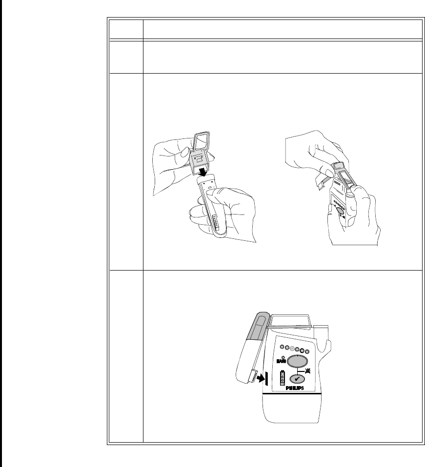
Draft - 1 Aug 08
Pairing Non-networked Devices
10-18 Pairing Monitoring Devices
Step Action
1 Remove the protective cover from the transceiver’s monitor/service
port.
2 Position the rubber cover over the top of the SRRA. Attach the
connected strap around the transceiver above the Leadset Insertion
Guide.
3 Insert the SRRA connector in the monitor/service port.

Draft - 1 Aug 08
Pairing Non-networked Devices
Pairing Monitoring Devices 10-19
To pair the transceiver to the monitor:
1. Press the Check Button on the transceiver. The measurement selection key
on the monitor will change to show the "assign telemetry" icon .
2. Select the assing telemetry icon.
3. In the Assign Telemetry Device menu, select the correct equipment label
for the device.
When connected, the icon appears at the Information Center.
The transceiver is assigned to the monitor. A "Tele Device Assigned" message
appears on the monitor, a tone sounds at the transceiver and its Leads Off
indicators light to indicate the successful assignment. If the ECG wave now
appears on the monitor, the signal from the transceiver is successfully
transmitting to the monitor. To confirm that the correct transceiver has been
assigned, open the ECG Setup menu by touching the ECG waveform or HR
numeric. The title of the menu contains the equipment label of the transceiver.
Check that this is the correct label.
If the transceiver goes out-of-range or loses the short-range radio connection,
monitoring at the Information Center remains, however monitoring at the patient
monitor is no longer possible. ECG Leads Off and Tele Disconnected INOPs are
displayed.
If the devices are unassigned, the short-range radio connection is ended.
Unassigning
Transceiver
with SRRA
at the
Monitor
Because the monitor does not have a connection to the Information Center, you
must manually end the assignment and the short range radio connection.
1. Select the Measurement Selection key.
2. In the Measurement Selection window, select the Tele pop-up key.
3. In the Tele device window select Unassign Tele.
Alarm
Behavior
(Non-
networked)
When the transceiver is paired to a non-networked monitor, alarms are generated
independently at both the Information Center and the bedside monitor. Alarms
are not synchronized. When you adjust alarm settings at the monitor, the
changes do not take effect at the Information Center and vice versa.

Draft - 1 Aug 08
Pairing Non-networked Devices
10-20 Pairing Monitoring Devices
The following table summarizes alarm behavior when a transceiver is paired
with an IntelliVue bedside monitor without network connection. For detailed
information, see the IntelliVue Patient Monitor Instructions for Use and the
IntelliVue Information Center Instructions for Use.
Where Initiated Effect at Bedside Effect at Information Center
Silence
Bedside Silences bedside alarms. No effect.
Information Center No effect Silences telemetry alarms.
Suspend/Pause
Bedside Suspends/Pauses bedside and
telemetry alarms. Suspends/Pauses telemetry alarms.
All Arrhythmia alarms are off.
Information Center No effect
Suspend/Pause not available at the
Information Center
No effect.
Suspend/Pause not available at the
Information Center
Standby
Bedside Bedside put into standby state. Measurements from bedside
disappear. Telemetry monitoring
continues.
Information Center N/A
Standby not available at the
Information Center.
N/A
Standby not available at the
Information Center.
Resume Monitoring
Bedside Bedside resumes monitoring Measurements from the bedside
reappear, for example NBP and/or
Temp, in the Patient Window.
Information Center N/A
Resume Monitoring not available at
the Information Center.
N/A
Resume Monitoring not available at
the Information Center.

Draft - 1 Aug 08
Pairing Non-networked Devices
Pairing Monitoring Devices 10-21
More Bed
Alarms The More Bed Alarms INOP is displayed at the Information Center when a
physiological alarm or INOP is generated by the bedside that is not included in
the group of alarms that is transmitted to the Information Center by the
transceiver. The INOP will display using the corresponding severity color of the
actual alarm. For example, should the bedside monitor generate a "***DESAT
alarm", it will display at the Information Center as a red, !!!More Bed Alarms
INOP.
WarningWarning
***DESAT and ***<Pressure> HIGH alarms from the bedside monitor will
appear as red, !!!More Bed Alarms INOPs at the Information Center.

Draft - 1 Aug 08
Pairing Non-networked Devices
10-22 Pairing Monitoring Devices
Short-
Range
Radio Error
Conditions
The following table describes error conditions that may occur when the
transceiver is paired with the monitor (MP5, MP2 and X2 IntelliVue Patient
Monitors only) via short-range radio capability.
Condition Description Action
Tele Disconnected INOP
displayed at the monitor
and the Information Center.
Short-range radio connection
between the transceiver and
MP5T has been lost due to a
failure of the short-range radio
connection.
There are too many short-range
radios operating in the same
vicinity (maximum of 4 per radio
channel).
If the disconnection is not
intentional:
Identify and remove the
interference sources.
Reduce the number of
devices equipped with
short-range radio capability.
No Signal INOP displayed
at the Information Center. The short-range radio is not
installed correctly.
There is interference from
telemetry or ISM radio sources.
The transceiver is outside the
coverage area.
Note—The typical coverage area
between the monitor and
transceiver is 15 ft.
Contact service personnel.
Identify and remove the
interference source.
Make sure the location of
the transceiver is in the
coverage area.
Battery LowT INOP
displayed at the monitor
and the Information Center.
When operating wirelessly, the
bedside monitor is no longer
providing power to the
transmitter, and battery capacity
is diminished. 15 minutes of
monitoring time remain.
Insert new AA batteries in
the transceiver.

Draft - 1 Aug 08
Pairing Non-networked Devices
Pairing Monitoring Devices 10-23
Replace BatteryT INOP
displayed at the monitor
and the Information Center.
When operating wirelessly, the
bedside monitor is no longer
providing power to the
transmitter, and battery capacity
is now depleted. There is no
monitoring occurring at either
the monitor or the Information
Center.
Insert new AA batteries in
the transceiver.
Absence of successful
association sound/visual
indicator.
The bedside monitor and the
transceiver are not
communicating with each other.
Monitoring at the Information
Center only.
Repeat the device
assignment procedure.
Central: Tele Only INOP When the transceiver is wirelessly
paired with an X2 patient monitor
(no label) docked with a larger
networked MP series monitor,
and the network connection is
lost.
Restore the monitor’s
network connection.
Check Pairing INOP An X2 patient monitor with a
telemetry label is paired with a
larger networked MP series
monitor and subsequently the
transceiver is paired with the
same monitor. Only one
transceiver can pair with the
monitor.
Select the correct device to
be paired.
Condition Description Action

Draft - 1 Aug 08
Pairing Non-networked Devices
10-24 Pairing Monitoring Devices
WarningWarning
When monitoring using short range-radio capability, there are numerous
causes of radio interference, (e.g. microwave ovens, bluetooth devices,
DECT phones, coverage area limitations) that may disrupt monitoring
momentarily or for extended periods. For more information on reducing
interference, see “Optimizing ECG Measurement Performance” on page
6-29.
Draft - 1 Aug 08
Maintenance, Cleaning & Troubleshooting 11-1
Introduction
11
Maintenance, Cleaning &
Troubleshooting
All installation tasks are performed by Service personnel and are described in
detail in the service documentation accompanying the system. This chapter
provides procedures for maintaining the equipment after installation including
assigning labels for replacement transceivers, keeping the transceiver clean, and
troubleshooting common problems. It includes the following sections:
• Maintenance . . . . . . . . . . . . . . . . . . . . . . . . . . . . . . . . . . . . . . . . . . . . 11-2
• Cleaning and Sterilization. . . . . . . . . . . . . . . . . . . . . . . . . . . . . . . . . . 11-4
• Troubleshooting . . . . . . . . . . . . . . . . . . . . . . . . . . . . . . . . . . . . . . . . 11-14

Draft - 1 Aug 08
Maintenance
11-2 Maintenance, Cleaning & Troubleshooting
Maintenance
Basic
Monitoring Before beginning monitoring on a patient:
• Check for any mechanical damage.
• Check all the external leads, plug-ins and accessories.
• Check all the functions of the instrument which are needed to monitor the
patient.
• Ensure that the instrument is in good, working order.
Do not use the IntelliVue transceiver for any monitoring procedure on a patient
if you identify features which demonstrate impaired functioning of the
instrument. Contact the service provider.
WarningWarning
Failure on the part of the responsible individual hospital or institution
employing the use of this equipment to implement satisfactory maintenance
as needed may cause undue equipment failure and possible health hazards.
Testing
Alarms Visual and auditory alarms appear at the Information Center. One method of
verifying visual and auditory alarms at the Information Center is to connect the
transceiver to an ECG or ECG/SpO2 simulator. By varying the ECG rate and
SpO2 value, alarms can be generated and confirmed for proper operation.
Label Assignment for Replacement Transceiver
During installation, an electronic equipment label is assigned to each transceiver
in a clinical unit so that the device can be identified during operation within the
wireless system. If a transceiver is lost, the Assign Label function at the
Information Center enables you to unassign the label from a lost transceiver, and
re-assign its label to a replacement transceiver. Labels are limited to those
available in an individual clinical unit. The Label Assignment function requires
a password for access, and its controls are available in English only.

Draft - 1 Aug 08
Maintenance
Maintenance, Cleaning & Troubleshooting 11-3
Re-assigning
an Equipment
Label
The following instructions enable you to reassign an equipment label from a lost
device to a replacement transceiver.
Note—If the leadset is attached during this procedure, the label assignment will
fail.
Step Action
1 At the Information Center, clear the sector that the original
Equipment Label was assigned to. (Patient Window -> Sector
Setup -> Clear Sector -> OK).
Note— Ensure that no patient is being monitored by the original
(lost) device before clearing the sector.
2 Select All Controls, then Label Assignment.
3 Enter password.
Note—The remaining screens will be in English only.
4Insert batteries into the replacement device, and remove the leadset,
if present.
All transceiver indicators should flash, and you should hear a double
tone repeated every 3 seconds, indicating that the transceiver has no
Equipment Label.
5 Select Refresh.
6 Select the MAC address of the replacement device from the “New
Devices” list. If the MAC address does not appear, remove the
batteries and reinsert them.
Note—The transceiver MAC address is located inside the battery
compartment.
7 Select the Equipment Label that was assigned to the unit’s previous
device from “Equipment Labels” list.

Draft - 1 Aug 08
Cleaning and Sterilization
11-4 Maintenance, Cleaning & Troubleshooting
Cleaning and Sterilization
The procedures in this section keep the transceiver clean and provide protection
against infectious agents and bloodborne pathogens. Both the outside of the
transceiver and the inside of the battery compartment must be kept free of dirt,
dust, and debris. The procedures in this section cover the following activities:
•Cleaning: removing surface contaminants from the device.
•EO Sterilization: using EO gas treatment to decontaminate cleaned
equipment.
Important—After exposure, the transceiver must be cleaned or cleaned and
EO sterilized as per the instructions contained herein.
8 Select Assign Label to initiate programming of the Equipment
Label into the replacement telemetry device
- AND -
within 10 seconds, press the Check button on the telemetry device.
Note—If 10 seconds pass without a button push, then repeat starting
with step 5.
When the label assignment is complete, the assignment will be
verified in the “Status” field.
9 Go back into Sector Setup, and select the Bed Label and
Equipment Label, followed by OK.
The transceiver goes through the normal startup sequence and starts
monitoring. Verify the signal in the appropriate Patient Sector.
Step Action

Draft - 1 Aug 08
Cleaning and Sterilization
Maintenance, Cleaning & Troubleshooting 11-5
Cleaning the Transceiver
Caution
Use of abrasive cleaning materials, or disinfectants or cleaning agents not listed
herein, on any part or component of the IntelliVue TRx or TRx+ transceiver may
damage the components. See the list of unsupported cleaners in the table below.
Caution
When cleaning the Monitor/Service port, do not use any stiff, rigid instruments,
tools, or other devices to clean debris in the port, as such actions will damage the
connector pins. A forceful water stream may be used after soaking for 5 minutes
to flush the port if necessary.
Approved
Cleaners
Cleaner Active Ingredient
Isopropyl Alcohol
based Isopropyl Alcohol (>70%)
Ethyl Alchohol
based Ethyl Alcohol (>70%)
Antibacterial Soap
and Water* Various
Hydrogen
Peroxide Hydrogen Peroxide (3%)
Chlorine Bleach Sodium Hyprochlorite (1:10 concentration, mixed <
24 hours)

Draft - 1 Aug 08
Cleaning and Sterilization
11-6 Maintenance, Cleaning & Troubleshooting
*To prevent damage, avoid the use of antibacterial soap and water and Cidex
inside the battery compartment.
Unsupported
Cleaners
Cidex* Gluteraldehyde (2.4%)
WipesPlus
Disinfecting
Wipes
Phenylphenol (0.28%), Benzyl-p-chlorophenol
(0.03%)
TechSpray
General Purpose
Cleaner
Isopropyl Alcohol
70% Surgical
Spirit Isopropyl Alcohol, Ethyl Alcohol mixed for alcohol >
70%
Virahol Hospital
Surface
Disinfectant
Towelette
Isopropyl Alcohol 70%
Cleaner Active Ingredient
Active
Ingredient Example
Quaternary
Ammonium based Virex Tb, SaniCloth HB, Purell Sanitizing Wipes,
Clorox Disinfecting Wipes
Phenol based
(>1%) 3M Phenolic Disinfectant Cleaner
Ether based Kleenaseptic

Draft - 1 Aug 08
Cleaning and Sterilization
Maintenance, Cleaning & Troubleshooting 11-7
Perform the following steps to clean the transceiver of visible surface
contamination.
Note—The cleaners listed above are also suitable for the optional Short Range
Radio Adapter (SRRA).
EO Sterilization
The transceiver can be subjected to EO sterilization four times per year for 2
years.
Equipment must first be cleaned (see “Cleaning the Transceiver” on page 11-5)
before this procedure is performed.
Note—If there is concern over cross-contamination due to leadsets or sensors,
new leadsets or sensors should be used.
Caution
The Short Range Radio Adapter cannot be sterilized. Remove the adapter before
sterilizing the transceiver.
Step Action
1 Remove the batteries and any cables or accessories.
2 Wipe the transceiver clean by using a cloth dampened modestly
with one of the approved cleaning agents listed in the table above.
3 If any visible residue remains in the Monitor/Service port, flush the
port with a forceful stream of water.
4 Rinse or wipe the transceiver with distilled water.
5 Allow to air-dry, or dry with a non-lint producing cloth.

Draft - 1 Aug 08
Cleaning and Sterilization
11-8 Maintenance, Cleaning & Troubleshooting
Equipment and
Materials
WarningWarning
EO is highly explosive, toxic, and a potential occupational carcinogenic and
reproductive hazard. Handle it with extreme care, following U.S.
Occupational Safety and Health Administration (OSHA) standards for EO
(29 CFR 1910.1047)*. Personnel exposure and/or room air must be
monitored per OSHA standards.
Vent sterilizer gas outdoors or to a suitable, evacuated container for
reprocessing, depending upon state, provincial, or country environmental
regulations. Do not vent sterilant indoors.
Vent aerator exhaust only to the outdoors.
* See “References” on page 11-11.
Use the following equipment and material to process the transceiver:
1. Ethylene Oxide gas (Allied Signal Oxyfume-2002™ or equivalent).
2. Gas sterilizer manufactured by American Sterilizer Company or other
appropriate manufacturer.
EO
Sterilization The following generic procedure can be used to supplement the sterilizer
manufacturer’s instructions, although the processing times, temperatures, and
EO concentrations must be equivalent to those given in this procedure in order
to achieve a sterility level of 10E-6.
Step Action
1Remove any obvious contamination from the equipment to be
processed using approved cleaners.
2Individually package each transceiver in standard central supply
room (CSR) wrapping material secured with EO color-change indi-
cator tape.

Draft - 1 Aug 08
Cleaning and Sterilization
Maintenance, Cleaning & Troubleshooting 11-9
3Apply -26 inHg +/- 1 (-12.77 psig +/- .49) vacuum to the empty
sterilizer chamber two times, to remove any residual EO or mois-
ture. Vent the vacuum pump to the outdoors to avoid toxic hazards
to personnel.
4Insert the equipment to be processed into the gas sterilizer.
5Heat the chamber and its contents to 54.4 +/- 2.8oC (130 +/- 5oF).
6Apply -26 inHg +/- 1 (-12.77 psig +/- .49) vacuum to the sterilizer
chamber.
7Humidify the chamber at 50% +/- 10% relative humidity for 20 to
30 minutes.
8Taking a minimum of five minutes, slowly introduce EO sterilant
until the sterilizer unit pressure gauge reaches 11 +/- 1 psig.
Note—At this pressure, the concentration of sterilant in the chamber
will be 600 +/- 50 mg/liter, regardless of the chamber size.
9Process the equipment to be processed as follows:
Pressure: 11 +/- 1 psig (established in the preceding step).
Time: 2-3 hours
Temperature: 54.4 +/- 2.8oC (130 +/- 5oF)
Step Action

Draft - 1 Aug 08
Cleaning and Sterilization
11-10 Maintenance, Cleaning & Troubleshooting
10 Extract the gas mixture from the sterilizer as follows:
WarningWarning
Comply with OSHA standards*. Do not vent sterilizer gas to the
room, but vent only outdoors or to a suitable, evacuated
container, depending upon state, provincial, or country environ-
mental regulations. (If the mixture is captured, it can be sepa-
rated commercially and the component gases re-used.)
* See “References” on page 11-11.
a. Pump the gas mixture out of the chamber until you ob-
tain a vacuum of -26 inHg +/- 1 (-12.77 psig +/-.49), re-
turning the mixture to a suitable evacuated container.
b. Return the sterilizer chamber to ambient pressure by in-
troducing air that has been bacterially filtered.
11 Air-wash the chamber and material as follows:
a. Apply -26 inHg +/- 1 (-12.77 psig +/- .49) vacuum to the
chamber and processed material again, to remove residu-
al EO. The vacuum pump must be vented to the out-
doors.
b. Return the sterilized chamber to ambient pressure by in-
troducing air that has been bacterially filtered.
12 Continue with the “Aeration Procedure” (following).
Step Action

Draft - 1 Aug 08
Cleaning and Sterilization
Maintenance, Cleaning & Troubleshooting 11-11
Aeration
Procedure
WarningWarning
To avoid chemical burns and toxic effects, the equipment must be aerated
after sterilization, as described. The aerator must have bacterial filters and
outdoor venting.*
See “References” on page 11-11.
Aerate the processed equipment by performing the following steps:
1 These values will produce EO and Ethylene Chlorohydrin residual levels in the
transceiver and patient cable plastic that meet ISO 10993-7 in conjunction with
AAMI Technical Information Report 19, that the FDA currently endorses.
References OSHA: Standard for acceptable levels of personnel exposure to Ethylene Oxide
Gas: 1 ppm on an eight-hour time-weighted average basis.
Reference: U.S.A. Federal Regulations 49 FR 25734/29 CFR Part 1910.1047,
June 22, 1984; final approval 50 FR 9800/2- CFR Part 1910.1047, March 12,
1985.
Step Action
1To dissipate residual EO, aerate the processed equipment with air
that has been bacterially filtered, using a mechanical aerator or
combination sterilizer/aerator as follows:1
Time: 8-9 hours
Temperature: 54.4 +/- 2.8oC (130 +/- 5oF)
Ventilation Frequency: At least 30 air exchanges per hour.
2 Continue with the “Test Procedure” (following).

Draft - 1 Aug 08
Cleaning and Sterilization
11-12 Maintenance, Cleaning & Troubleshooting
Test Procedure
Caution
You must perform this test each time you put a transceiver through the EO
sterilization process.
This test allows you to verify that patient information for both ECG and SpO2 (if
you are monitoring pulse oximetry) appear at the Information Center and at the
bedside. You can use this procedure with a Patient Simulator.
Note—This test assumes that the telemetry system and Information Center are
fully installed, and that you have performed the procedure to learn the
transceiver identity code.
Test the transceiver by performing the following steps. If the test indications do
not appear, refer to your service provider.
Step Action
1Perform a mechanical inspection of the transceiver (connectors,
battery door opening and closing, Telemetry and Check buttons).
2At the Information Center, select the telemetry bedside you are
testing.

Draft - 1 Aug 08
Cleaning and Sterilization
Maintenance, Cleaning & Troubleshooting 11-13
3Test the transceiver:
a. Put fresh batteries in the transceiver (without a leadset
attached) and close the battery door
Result: All six lead lights should flash, and one light
should remain on.
b. Attach a leadset to the ECG port, and attach an SpO2
sensor to the SpO2 port. If an ECG simulator is avail-
able, attach the ECG leads to the simulator and the SpO2
sensor to yourself. At TeleMon, set the SpO2 sample
rate to Continuous.
Result: An ECG trace and SpO2 information should be
visible on the Information Center display. All transceiv-
er lights should be off.
c. Disconnect the Right Arm lead for standard ECG or the
“I” electrode for EASI.
Result: The RA LED or the “I” lead LED should turn
on, and a Leads Off INOP should appear on the display
at the Information Center.
d. Reconnect the electrode.
4a. Connect the transceiver to TeleMon and observe the
ECG waveform and SpO2 numerics on the TeleMon dis-
play.
Result: The ECG waveform and SpO2 numerics should
be displayed on the TeleMon screen.
Step Action

Draft - 1 Aug 08
Troubleshooting
11-14 Maintenance, Cleaning & Troubleshooting
Troubleshooting
Basic Troubleshooting
Important—If changes are made to the Group Settings (how telemetry devices,
such as Access Points and Controllers, are grouped in order to provide coverage
for patients throughout the hospital), there will be a break in monitoring of all
transceivers within the Group(s) being modified. Monitoring will resume when
the new Group Settings are in place. Clinical settings will be unaffected by the
reconfiguration.
For problems with... see...
• ECG measurement “Optimizing ECG Measurement Performance”
on page 6-29.
“Using EASI Leads to Troubleshoot” on page 6-
28.
“Technical Alarms (INOPs)” on page 5-10.
•SpO
2 measurement “Optimizing SpO2 Measurement Performance”
on page 8-22.
“Technical Alarms (INOPs)” on page 5-10.
• Batteries “Battery Information” on page 4-13.
“Self Test” on page 4-11.
• Nurse call Nurse Call may have been turned off for the
patient. See “Telemetry Button” on page 9-6 for
directions on how to turn it on.
• Electromagnetic
Interference “Reducing Electromagnetic Interference” on
page 12-7.
• Short Range Radio
Performance “Short- Range Radio Error Conditions” on page
10-22

Draft - 1 Aug 08
Troubleshooting
Maintenance, Cleaning & Troubleshooting 11-15
Information
Signals If there is a connection failure within the IntelliVue Clinical Network, an
information signal will be generated. This information signal will be displayed
in the system message area on the Information Center where the affected
wireless patient monitoring device(s) (transceiver, access point, access point
controller, sync unit, or router) is assigned, as well as on all other Information
Centers connected to a common Database Server. The condition causing the
failure will be described in the Wireless Status Log, which is available in
Service Mode.
Information Signals
Information
Signal Description What to Do
Wireless
monitoring loss -
Contact Service
Note—This
information signal
appears on ALL
Information Centers
connected to a
common Database
Server.
Problem with wireless
network infrastructure
device(s).
Contact Service.
Note—Details about the
communication disruption
are available in the
Wireless Status Log.
Router failure
Call Service
Note—This
information signal
appears on ALL
Information Centers
connected to a
common Database
Server.
A router used in the
wireless network has
failed.
Contact Service.
Draft - 1 Aug 08
Troubleshooting
11-16 Maintenance, Cleaning & Troubleshooting
Draft - 1 Aug 08
Safety Standards & Specifications 12-1
Introduction
12
Safety Standards & Specifications
This chapter describes the regulatory standards that the product complies with,
along with product and measurement specifications. It includes the following
sections:
• Regulatory Information. . . . . . . . . . . . . . . . . . . . . . . . . . . . . . . . . . . . 12-2
• Electromagnetic Compatibility. . . . . . . . . . . . . . . . . . . . . . . . . . . . . . 12-5
• Battery Specifications. . . . . . . . . . . . . . . . . . . . . . . . . . . . . . . . . . . . . 12-8
• Radio Specifications . . . . . . . . . . . . . . . . . . . . . . . . . . . . . . . . . . . . . . 12-9
• Physical Specifications. . . . . . . . . . . . . . . . . . . . . . . . . . . . . . . . . . . 12-13
• Environmental Specifications. . . . . . . . . . . . . . . . . . . . . . . . . . . . . . 12-15
• Measurement Specifications. . . . . . . . . . . . . . . . . . . . . . . . . . . . . . . 12-16

Draft - 1 Aug 08
Regulatory Information
12-2 Safety Standards & Specifications
Regulatory Information
Intended Use The device is intended to provide ambulatory and bedside monitoring of
ECG and SpO2 parameters of adult and pediatric patients in professional
healthcare facilities. It is intended to be used by trained healthcare
personnel. It is not intended for home use.
Indications for
Use Indicated for use by health care professionals whenever there is a need for
monitoring the physiological parameters of patients. Intended for
monitoring, recording and alarming of multiple physiological parameters of
adult and pediatric patients in transport and hospital environments.
Rx Federal Law restricts this device to sale by or on the order of a physician.
Patient
Population This device is not for use with infant or neonatal patients.
Use of the transceiver is restricted to one patient at a time.
The components/accessories which come into contact with the patient’s skin
are in compliance with the relevant requirements of EN ISO 10993-1 for
Biocompatibility. The transceiver is not designed for direct contact with the
patient’s skin. The accompanying pouch is the appropriate means for
holding the transceiver.
Authorized EU
Representative Philips Medizin Systeme Deutschland
Hewlett-Packard-Strasse 2
D 71034, Boeblingen
Germany

Draft - 1 Aug 08
Regulatory Information
Safety Standards & Specifications 12-3
Safety
Standards The device complies with the following safety requirements for medical
electrical equipment:
• IEC 601-1:1988 + A1:1991 + A2:1995 General Requirements for Safety
(with worldwide deviations, including U.S. deviations)
• IEC 60601-1-1:2000 System Safety
• IEC 60601-1-2:2001 Electromagnetic Compliance
• IEC 60601-1-4:1996 Safety for Programmable Electrical Medical Systems
• ISO 10993-1:2003 Biocompatibility (for lead wires and pouch)
• ISO 9919:2005 Pulse Oximeters
• EN 865:1997 Particular Requirements for Pulse Oximeters
• AAMI EC 13:2002 Performance Standard, Cardiac Monitors
Essential Performance
The IntelliVue Telemetry System provides Essential Performance (EP) under
normal operating conditions (includes EMC exposure) only as a complete
Medical Electrical System, consisting of the TRx4841A or TRx4851A
Transceivers, the IntelliVue Telemetry Network Infrastructure, the M3150
Information Center, the M2636C TeleMon Companion Monitor (optional), and
the M8105A/T MP5/5T, M8102A MP2, and M3002A X2 IntelliVue Patient
Monitors (optional).
The IntelliVue Telemetry System achieves its Essential Performance exclusively
through alarm generation at the M3150 Information Center.
The IntelliVue Telemetry System protects the patient from unacceptable
immediate clinical risk by generating specific Physiological Alarms when
appropriate. If the System cannot generate Physiological Alarms, then relevant
Severe or Hard Technical Alarms (Inoperative Conditions) are created.

Draft - 1 Aug 08
Regulatory Information
12-4 Safety Standards & Specifications
System Classification
The TRx4841A and TRx4851A Transceivers are FDA Class II devices. They
have the following characteristics.
FCC
Compliance
(M4840A/
USA only)
Operation of this equipment requires the prior coordination with a frequency
coordinator designated by the FCC for the Wireless Medical Telemetry Service.
The transceiver and the IntelliVue Telemetry System are subject to radio
frequency interference. In the event of suspected radio frequency interference
with your device, contact your service provider. This device complies with Parts
15 and 95H of the Federal Communications Commission (FCC) Rules.
Operation is subject to the condition that this device does not cause harmful
interference.
Pursuant to Part 15.21 of the FCC Rules, any changes or modifications to this
equipment not expressly approved by Philips Medical Systems may cause
harmful radio frequency interference, and void your authority to operate this
equipment.
Characteristic Definition
Internally Powered
Equipment The TRx4841Aand TRx4851A transceivers are
internally powered devices.
Continuous Operation All equipment is Ordinary Equipment, IPX0, and
provides continuous operation
Type CF
Defibrillation Proof The TRx4841A and TRx4851A transceivers are
Type CF Defibrillation Proof relative to ECG and
SpO2 patient applied parts.
Water Resistance IPX0, Non-Protected
When placed inside a Philips-specified carrying
pouch with the velcro closures secured, the
combination of the transceiver and pouch will
withstand showering for up to 10 minutes.

Draft - 1 Aug 08
Electromagnetic Compatibility
Safety Standards & Specifications 12-5
Industrie
Canada
Compliance
(Canada)
This Class A digital apparatus complies with Canadian ICES-003.
Cet appareil numérique de la classe A est conforme à la norme NMB-003 du
Canada.
AC Power
Source The system is not intended for connection to the public mains as defined in
CISPR11.
Software
Hazard
Prevention
Potential hazards arising from errors in the software program have been
identified. Mitigations applied to reduce the associated risk of such hazards are
included as part of the Risk Management, Clinical Evaluation, and Verification
and Validation phases of the product’s development.
Electromagnetic Compatibility
Medical electrical equipment can either generate or receive electromagnetic
interference. This product has been evaluated for electromagnetic compatibility
(EMC) with the appropriate accessories according to IEC 60601-1-2:2001, the
international standard for EMC for medical electrical equipment. This IEC
standard has been adopted in the European Union as the European Norm, EN
60601-1-2:2001.
Radio frequency (RF) interference from nearby transmitting devices can degrade
performance of the product. Electromagnetic compatibility with surrounding
devices should be assessed prior to using the product.
Fixed, portable, and mobile radio frequency communications equipment can also
affect the performance of medical equipment. See your service provider for
assistance with the minimum recommended separation distance between RF
communications equipment and the product.
The cables, sensors/transducers, and other accessories for which compliance is
claimed are listed in the Service and User documentation accompanying the
product.

Draft - 1 Aug 08
Electromagnetic Compatibility
12-6 Safety Standards & Specifications
WarningWarning
The use of accessories, transducers and cables other than those specified in
the product service and user documentation can result in increased
electromagnetic emissions or decreased immunity of the product.
WarningWarning
Short-range radio connections are subject to interruption due to
interference from other radio sources in the vicinity, including microwaves,
bluetooth devices, and DECT phones. Outside the frequency band and 5%
above and below, i.e. the exclusion band according to IEC 60601-1-2, the
short-range radio connection is immune up to 3V/m in the frequency range
from 80MHz to 2.0 GHz and up to 1V/m in the frequency range from 2.0 to
2.3 GHz. Depending on the strength and duration of the interference, the
interruption may occur for an extended period. Any interruption of the
signal due to interference, moving out of range, or for other reasons is
indicated with a Tele Disconnected INOP message.
WarningWarning
The product should not be used next to or stacked with other equipment. If
you must stack the product, you must check that normal operation is
possible in the necessary configuration before the product is used on
patients.
Draft - 1 Aug 08
Electromagnetic Compatibility
Safety Standards & Specifications 12-7
Reducing Electromagnetic Interference
The transceiver and associated accessories can be susceptible to interference
from other RF energy sources and continuous, repetitive, power line bursts.
Examples of other sources of RF interference are other medical electrical
devices, cellular products, information technology equipment, and radio/
television transmission. If interference is encountered, as demonstrated by
artifact on the ECG or dramatic variations in physiological parameter
measurement values, attempt to locate the source. Assess the following:
• Is the interference due to misplaced or poorly applied electrodes or
sensors? If so, re-apply electrodes and sensors correctly according to
directions in Chapter 6. ECG Monitoring.
• Is the interference intermittent or constant?
• Does the interference occur only in certain locations?
• Does the interference occur only when in close proximity to certain
medical electrical equipment?
Once the source is located, attempt to attenuate the interference by distancing
the transceiver from the source as much as possible. If assistance is needed,
contact your local service representative.
Restrictions
for Use Artifact on ECG and other physiological waveforms caused by electromagnetic
interference should be evaluated by a physician or physician authorized
personnel to determine if it will negatively impact patient diagnosis or treatment.

Draft - 1 Aug 08
Battery Specifications
12-8 Safety Standards & Specifications
Battery Specifications
Battery Type
Battery Life Note—The battery life specifications listed below are based on Duracell MN
1500 batteries. Battery life for other brands may differ.
Equipment Specification
Battery Type 2 fresh AA disposable alkaline batteries
Operating Mode Battery Life
ECG Only 50 hours
ECG/SpO2 Continuous 18 hours
ECG/SpO2 Spot Check between 18 hours and 50 hours, depending on
usage rate
ECG Only w/ SRRA 38 hours
ECG/SpO2 Continuous
w/ SRRA 14 hours
ECG/SpO2 Spot Check w/
SRRA between 14 and 38 hours, depending on usage
rate

Draft - 1 Aug 08
Radio Specifications
Safety Standards & Specifications 12-9
Transceiver
Current
Radio Specifications
TRx4841A
Operating Mode Nominal Current
ECG Only 51.3 mA @ 2.4V (TRx4841A)
51.0 mA @ 2.4V (TRx4851A)
ECG/SpO2 Continuous 116 mA @ 2.4V
Parameter Specification
Frequency Ranges Bands: 1395-1400 MHz and 1427-1432 MHz
Channel Spacing: 1.6 MHz
RF Output Power 8 dBm +2/-3 dB (3.2 mW to 10 mW), into
antenna load @ nominal battery voltage
Transceiver Frequency
Accuracy during normal
operation
+/- 15 KHz relative to channel frequency,
includes temperature compensation and aging
effects
Modulation Type FSK with Root Raised Cosine filtering
(1M60Q7D)

Draft - 1 Aug 08
Radio Specifications
12-10 Safety Standards & Specifications
TRx4851A
Out of Band Spurious
Emission Levels:
• <= 1394 MHz, >=
1401 MHz
• <= 1428 MHz, >=
1433 MHz
<-41 dBm in 1 MHz bandwidth for FCC limit
Occupied bandwidth as
defined by power in 99%
BW
< +/- 800 KHz
Parameter Specification
Parameter Specification
Frequency Range ISM Band: 2400 - 2483.5 MHz
Channel Spacing: 1.728 MHz
RF Output Power FCC: 17 dBm +/- 1 dB (40 mW to 63 mW,
nominal 50 mW), into antenna load @
nominal battery voltage
ETSI: 12 dBm +/- 1 dB (13 mW to 20 mW,
nominal 16 mW), into antenna load @
nominal battery voltage
ARIB: 13.5 dBm +/- 1 dB (18 mW to 28 mW,
nominal 22 mW), into antenna load @
nominal battery voltage
Transceiver Frequency
Accuracy during normal
operation
<+ 60 /- 100 KHz relative to channel
frequency, includes temperature compensation
and aging effects

Draft - 1 Aug 08
Radio Specifications
Safety Standards & Specifications 12-11
Modulation Type GFSK, Gaussian Frequency Shift keying
(1M40Q7D)
Modulation Bandwidth Typically 1.4 MHz (20 dB Bandwidth)
Out of Band Spurious
Emission Levels Meets ETSI, RS210, FCC, ARIB standards
Parameter Specification

Draft - 1 Aug 08
Radio Specifications
12-12 Safety Standards & Specifications
SRRA
Parameter Specification
Frequency Ranges ISM Band: 2400-2483.5MHz
Radio Channel assignment 16 Radio Channel assigned, Fc= 2405 +5*(k-
11)MHz, k=11,12,…,26
Frequency Control Controlled via the bedside monitor, selects clear
channel at time of install
RF Output Power 0 dBm +0/-3dB (0.5 mW to 1 mW), into Antenna
load.
Transceiver Frequency
Accuracy during normal
operation
<+/-40ppm, includes temperature compensation &
aging effects
Modulation Type Direct Sequence Spread Spectrum(DSSS), O-QPSK
with half sine pulse shaping modulation
(1M40Q7D)
Modulation Bandwidth >500KHz, typically +/-950KHz (6dB Bandwidth),
typically +/-1.4MHz (20dB Bandwidth)

Draft - 1 Aug 08
Physical Specifications
Safety Standards & Specifications 12-13
Physical Specifications
ECG-only
Transceiver
ECG/SpO2
Transceiver
Parameter Specification
Height 140 mm (5.6 in)
Width 75 mm (3 in)
Depth 28.5 mm (1.14 in)
Weight
• without batteries or
leadset
• with batteries only
• with batteries and 3-
wire leadset
• <165 g (5.8 oz)
• <210 g (7.4 oz)
• <284 g (10 oz)
Volume 215 cm3
Parameter Specification
Height 140 mm (5.6 in)
Width 88 mm (3.52 in)
Depth 37 mm (1.48 in)

Draft - 1 Aug 08
Physical Specifications
12-14 Safety Standards & Specifications
SRRA
Weight
• without batteries or
leadset
• with batteries only
• with batteries and 5-
wire leadset
• <205 g (7.2 oz)
• <255 g (9.0 oz)
• <324 g (11.5 oz)
Volume 300 cm3
Parameter Specification
Parameter Specification
Height 88 mm (3.5 in)
Width 25 mm (1 in)
Depth 13 mm (.5 in)
Weight 25g (1 oz)

Draft - 1 Aug 08
Environmental Specifications
Safety Standards & Specifications 12-15
Environmental Specifications
Parameter Specification
Temperature
• Operating
•Storage • 0 t 37 oC (32 to 99o F)
•-40
o C to 60o C (-40 to 140o F) without batteries
Humidity
• Operating
•Storage •<
95% RH at 37o C (99o F) non-condensing
•<
90% RH at 60o C (140o F) without batteries
Altitude
• Operating &
Non-operating 0 to 3,048 m (10,000 ft)

Draft - 1 Aug 08
Measurement Specifications
12-16 Safety Standards & Specifications
Measurement Specifications
ECG
Parameter Specification
ECG channel
transmitted Leads
• 3 electrodes
• 5 electrodes
• 5 electrodes,
EASI
• 6 electrodes
• Channel #1 = I, II, or III
• Channel #1 = II
Channel #2 = III
Channel #3 = MCL
• Channel #1 = Va-i
Channel #2 = Va-s
Channel #3 = Ve-s
• Channel #1= II
Channel #2 = III
Channel #3 = Va
Channel #4 = Vb
Resolution 5 μV
ECG Input Differential, defibrillator protected against 360
joules discharge into a 100 ohm load
Input Impedance > 5 megohms (@ 10 Hz
Input Dynamic Range +/- 9 mV
DC Offset Range +/- 320 mV
CMRR > 90 dB @ 50, 60 Hz
Bandwidth +/- 3 dB 0.05 to 40 Hz

Draft - 1 Aug 08
Measurement Specifications
Safety Standards & Specifications 12-17
Gain Accuracy +/- 5% at 25 oC (77 oF)
Noise Referred to ECG
Input (Peak-to-Peak) AAMI: 30 μV (as per AAMI EC 13)
Lead Wires 3, 5 or 6-wire leadset compatible with IntelliVue
Patient Monitor, AAMI/IEC color codes
Time to baseline from
Defibrillator AAMI: 5 s max (until ECG wave is on display
but not yet centered, monitoring bandwidth)
Pacer Rejection
Performance
(Pace pulses with no
tails).
Positive pacers1
Amplitude Width
+2 to +700 mV 0.1, 0.2, 0.5 and 1.0 ms
+2 to +500 mV 1.5 ms
+2 to +400 mV 2 ms
Negative pacers1
Amplitude Width
-2 to -700 mV 0.1, 0.2, 0.5 and 1.0 ms
-2 to -500 mV 1.5 ms
-2 to -400 mV 2 ms
1 Philips does not claim, verify, or validate
support for all available pacemakers.
EMC Performance
Limits, radiated
immunity
Meets Essential Performance, but may observe
some waveform disturbance over 181 to 202 MHz
@ >1.8 V/m and 203 to 213 MHz @ > 1.0 V/m
Parameter Specification

Draft - 1 Aug 08
Measurement Specifications
12-18 Safety Standards & Specifications
SpO2
Parameter Specification
SpO2 Measurement
Range (Calibration and
Display)
0 to 100%
SpO2 Accuracy See table following.
SpO2 Resolution 1%
SpO2 Numerics -
Averaging 10 seconds
Note—The update rate for the SpO2 pulse
oximetry value and pulse rate is typically 1
second. This can be extended to a max. 60 s
when NIBP is measured on the same limb, with a
corresponding INOP message after a max. of 30
s, indicating that the displayed values are not
current values.
The effect of SpO2 pulse oximetry on data
averaging is internally controllable by the
transmitter, with no user controls.
SpO2 & Pulse Numerics
- Update Rate Transmitted once per second.
Pleth Wave- Sampling
Rate 125 sps
Technical Alarms
(INOPs) Triggered if the sensor is disconnected, if a pulse
is not detected, if the signal is noisy, if light
interference is detected, if the sensor is defective,
if the measurement is erratic, or if the module is
malfunctioning

Draft - 1 Aug 08
Measurement Specifications
Safety Standards & Specifications 12-19
Wavelength Range 500 to 1000 nm
Note—Information about wavelength range can
be especially useful to clinicians (e.g., clinicians
performing photodynamic therapy).
Pulse Rate
Measurement
(available only with
Continuous SpO2)
Range: 30 to 300 bpm
Accuracy: +/- 2%
Resolution: 1 bpm
Display of SpO2
numerics SpO2 values are displayed as xxx % SpO2T to
meet ISO/EN standard EN 865.
Maximum Optical
Output Power < 15 mW
Parameter Specification

Draft - 1 Aug 08
Measurement Specifications
12-20 Safety Standards & Specifications
SpO2
Sensor
Accuracy
.
Type Description Model
Number
Accuracy%
Arms (70-100%
Range)
Philips
Reusable
Sensors
Adult Finger M1191A 2.0
Adult Finger M1191AL 2.0
Adult Finger M1191ANL 2.0
Adult Finger* M1191T 3.0
Adult Finger M1196A 3.0
Adult Finger M1196T 3.0
Pediatric Finger M1192A 2.0
Pediatric Finger* M1192T 3.0
Pediatric Finger M1192AN 2.0
Adult/Pediatric Ear M1194A 3.0
Adult/Pediatric Ear M1194AN 3.0
* Requires M1943A or M1943AL adapter cable.

Draft - 1 Aug 08
Measurement Specifications
Safety Standards & Specifications 12-21
Type Description Model
Number
Accuracy%
Arms (70-100%
Range)
Philips
Disposable
Sensors
Adult Finger M1901B 2.0
Adult Finger M1902B 2.0
Pediatric Finger M1903B 2.0
Adult Finger M1904B 2.0
Adult/Pediatric Finger M1131A 3.0

Draft - 1 Aug 08
Measurement Specifications
12-22 Safety Standards & Specifications
Nellcor
Disposable
Sensors
(not
available
from
Philips)
OxiCliq A, Adult N/A 3.0
OxiCliq N, Adult >40 kg
(88 lb) N/A 3.0
OxiCliq P, Pediatric N/A 3.0
OxiMax MAX-A, Adult
>30 kg (66 lb) N/A 3.0
OxiMax MAX-AL,
Adult >30 kg (>66 lb) N/A 3.0
OxiMax MAX-N, Adult
>40 kg (>88 lb) N/A 3.0
OxiMax MAX-P,
Pediatric 10-50 kg (22-
110 lb)
N/A 3.0
Oxisensor II D-20,
Pediatric 10-50 kg (22-
110 lb)
N/A 3.0
Oxisensor II D-25, Adult
>30 kg (>66 lb) N/A 3.0
Oxisensor II N-25, Adult
>40 kg (>88 lb) N/A 3.0
Type Description Model
Number
Accuracy%
Arms (70-100%
Range)

Draft - 1 Aug 08
Accessories A-1
Introduction
A
Accessories
This appendix lists the accessories for use with the Transceiver. Accessories are
subject to change. Some accessories are not supplied by Philips.
To order accessories, visit the Philips Medical Supplies website located at the
following web address: http://shop.medical.philips.com, or contact your local
Philips representative.
Accessory Safety
WarningWarning
Use only Philips-approved accessories. Use of product accessories (ECG
leadsets, SpO2 sensors, etc.) other than those specified in this manual may:
- lead to patient injury
- result in increased electromagnetic emissions or decreased immunity of
the product
WarningWarning
Reuse: Never reuse disposable sensors, accessories and so forth that are
intended for single use, or single patient use only.
Packaging: Do not use a sterilized accessory if the packaging is damaged.

Draft - 1 Aug 08
Transceiver Accessories
A-2 Accessories
Transceiver Accessories
Pouches
Protective
Covers
Monitor
Interface
Cable
Order Number Description
989803137821 Telemetry Pouch, box of 5
989803137831 Telemetry Pouch, box of 50
989803140371 Telemetry Pouch, case of 200
Order Number Description
989803140431 Protective Cover for Monitor/Service port (ECG-only
Transceiver), package of 10
989803140451 Protective Cover for Monitor/Service port (ECG/
SpO2Transceiver), package of 10
989803140441 Protective Cover for SpO2 port (ECG/SpO2
Transceiver), package of 10
Order Number Description
989803143481 Transceiver tether cable
989803143491 Telemon tether cable
989803146911 MP5/MP5T Patient Monitor tether cable

Draft - 1 Aug 08
ECG Accessories
Accessories A-3
A Sales and Support
Short
Range-
Radio
Adapter
ECG Accessories
Electrodes
Skin Prep
Paper
Order Number Description
989803158241 Short-Range Radio Adapter
989803160331 Short Range Radio Adapter Strap (1 package of 10)
Order Number Description
M2202A Radio Translucent Foam Electrodes, 60 packages of 5
(300 per box)
40489E Paper Tape Electrodes, 10 packages of 30 (300 per
box)
40493D Foam Electrodes, 60 packages of 5 (300 per box)
40493E Foam Electrodes, 10 packages of 30 (300 per box)
Order Number Description
989803134771 Skin Preparation Sheets, 10 preps/sheet, package of
10 sheets

Draft - 1 Aug 08
ECG Accessories
A-4 Accessories
Leadsets
Order Number Description
989803151991 AAMI 3-wire Leadset, Snap, 79 cm (30 ”)
989803151971 AAMI 3-wire Leadset, Grabber ,79 cm (30 ”)
989803152071 AAMI 5-wire Color Leadset, Snap, 79 cm (30 ”)
989803152051 AAMI 5-wire Color Leadset, Grabber, 79 cm (30 ”)
989803152151 AAMI 6-wire Color Leadset, Snap, 79 cm (30 ”)
989803152131 AAMI 6-wire Color Leadset, Grabber, 79 cm (30 ”)
989803152001 IEC 3-wire Leadset, Snap, 79 cm (30”)
989803151981 IEC 3-wire Leadset, Grabber, 79 cm (30”)
989803152081 IEC 5-wire Color Leadset, Snap, 79 cm (30”)
989803152061 IEC 5-wire Color Leadset, Grabber, 79 cm (30”)
989803152161 IEC 6-wire Color Leadset, Snap, 79 cm
989803152141 IEC 6-wire Color Leadset, Grabber, 79 cm

Draft - 1 Aug 08
ECG Accessories
Accessories A-5
A Sales and Support
Alignment
Guides
Detachable
Shields
Order Number Description
989803140401 Single ECG Alignment Guide, package of 10
989803140411 Single ECG Alignment Guide, tethered, package of
10
989803140421 Double ECG Alignment Guide, package of 10
Order Number Description
989803153031 3-wire Leadset Detachable Shield, package of 10
989803153041 5-wire Leadset Detachable Shield, package of 10
989803153051 6-wire Leadset Detachable Shield, package of 10

Draft - 1 Aug 08
SpO2 Accessories
A-6 Accessories
SpO2 Accessories
Reusable
Sensors
Order Number Description
M1191A Philips Adult Finger Sensor, 2m (6.6 feet)
M1191AL Philips Adult Finger Sensor, 3m (9.8 feet)
M1191B Philips Adult Finger Sensor, 2 m (6.6 feet)
M1191BL Philips Adult Finger Sensor, 3 m (9.8 feet)
M1191T Philips Adult Finger Sensor, 0.45 m (1.5 feet)
M1192A Philips Pediatric Finger Sensor, 1.5 m (4.9 feet)
M1192T Philips Pediatric Finger Sensor, 0.45 m (1.5 feet)
M1194A Philips Adult & Pediatric Ear Sensor, 1.5 m (4.9 feet)
M1196A Philips Adult Finger Clip Sensor (8-pin), 3 m (9.8 feet)
M1196T Philips Adult Finger Clip Sensor (9-pin), 0.90 m (2.9 feet)
N/A from Phillips Nellcor Dura-Y D-YS Adult and Pediatric
N/A from Phillips Nellcor DS-100A Adult and Pediatric
N/A from Phillips Nellcor Oxiband OXI-A/N Adult and Pediatric
N/A from Phillips Nellcor Oxiband OXI-P/I Adult and Pediatric
N/A from Phillips Nellcor D-YSE Adult
N/A from Phillips Nellcor D-YSPD Pediatric
989803148281 Masimo LNCS DC-I Adult
989803148291 Masimo LNCS DC-IP Pediatric
989803148301 Masimo LNCS TC-I Ear Clip

Draft - 1 Aug 08
SpO2 Accessories
Accessories A-7
A Sales and Support
Disposable
Sensors -
Single Use
Note—OxiCliq, OxiMax and Oxisensor II sensors are not available from Philips
in the USA or Canada. In those countries, contact Nellcor Incorporated directly.
Order Number Description
M1901B *Philips Adult >40 kg (>88 lb)
M1902B *Philips Pediatric 3-20 kg (7-44 lb)
M1903B *Philips Pediatric 10-50 kg (22-110 lb)
M1904B *Philips Adult >30 kg (>66 lb)
M1131A *Philips Adult/Pediatric >20 kg (>44 lb)
N/A from Philips *Nellcor Adhesive OxiCliq A, Adult
N/A from Philips *Nellcor Adhesive OxiCliq N, Adult >40kg (>88 lb)
N/A from Philips *Nellcor Adhesive OxiCliq P, Pediatric
N/A from Phillips *Nellcor Adhesive OxiCliq I, Infant 3-20 kg
N/A from Philips *Nellcor OxiMax MAX-A, Adult >30 kg (>66 lb)
(M1904B equivalent)
N/A from Philips *Nellcor OxiMax MAX-AL, Adult >30 kg (>66 lb)
N/A from Philips *Nellcor OxiMax MAX-N, Adult >40 kg (>88 kg)
(M1901B equivalent)
N/A from Philips *Nellcor OxiMax MAX-P, Pediatric 10-50 kg (22-110 lb)
(M1903B equivalent)
N/A from Philips *Nellcor OxiMax MAX-I, Infant 3-20 kg
(M1902B equivalent)
N/A from Philips *Nellcor Oxisensor II D-20, Pediatric 10-50 kg (22-110 lb)
N/A from Philips *Nellcor Oxisensor II D-25, Adult >30 kg (>66 lb)
N/A from Philips *Nellcor Oxisensor II N-25, Adult >40 kg (>88 lb)
989803140261 Masimo LNOP PDT Pediatric
N/A from Philips Masimo LNOP PDTx Pediatric

Draft - 1 Aug 08
SpO2 Accessories
A-8 Accessories
989803148231 Masimo LNCS ADTx Adult
989803148241 Masimo LNCS PDTx Pediatric
N/A from Philips Masimo LNCS Neo-3 Adult
* Uses Philips M1943A or Nellcor OC-3 Adapter Cable.
Order Number Description

Draft - 1 Aug 08
SpO2 Accessories
Accessories A-9
A Sales and Support
Adapter
Cables Note—Adapter cables are not available from Philips in Canada or Japan. In
those countries, contact Nellcor Incorporated directly.
Wristband
Order Number Description
M1943A Adapter cable for Nellcor SpO2 sensor, 2 m (6.6 ft)
M1943AL Adapter cable for Nellcor SpO2 sensor, 3 m (9.8 ft)
Order Number Description
M1627A Wristband, package of 10
Draft - 1 Aug 08
SpO2 Accessories
A-10 Accessories
Draft - 1 Aug 08
Sales and Support Offices B-1
Introduction
B
Sales and Support Offices
Please call your local Philips Medical Systems sales office listed in your
telephone directory or a Philips Medical Systems regional office listed below for
the location of your nearest sales office.
On the web
www.medical.philips.com
Via email
medical@philips.com
By fax
+31 40 27 64 887
By postal service
Philips Medical Systems
Global Information Center
P.O. Box 1168
5602 BD Eindhoven
The Netherlands
Asia
Tel: +852 2821 5888
Europe, Middle East, Africa
Tel: +31 40 27 63005
Latin America
Tel: +55 11 2125 0764
North America
Tel: +1 800 229 6417
Draft - 1 Aug 08
B-2 Sales and Support Offices

Draft - 1 Aug 08
Index-1
Index
A
alarms
indicators, 5-2
more bed alarms, 10-21
physiologic, 5-5
SpO2, 8-20
technical, 5-11
testing indicators, 5-2
testing, 11-2
turning off, 4-3
audible tones
definitions, 3-10
start-up, 4-3
auditory information signals
see audible tones, 3-10
B
battery
inserting, removing, 4-14
life, 4-18, 12-8
safety, 2-5, 4-13
storing, 4-16
type, 4-14
buttons 3-3
C
configuration
group settings, 11-14
label assignment, 11-2
Telemetry Setup, 9-6
unit settings, 9-9
controls
buttons, 3-3
indicators, 3-4
labels,back, 3-8
labels,front, 3-5
on/off, 4-2
other marks, 3-8
ports, 3-6
D
device location 9-4
dropouts (ECG), 6-30
E
ECG
measuring, 6-4
optimizing performance, 6-29
electrodes
placement, 6-10
skin prep, 6-11
electromagnetic interference, 12-5
essential performance, 12-3
F
fallback, 6-27
find device, 9-3
G
group settings 11-14
group settings, 11-14
I
Information Center
transceiver use with, 1-9
information signals, 11-15
INOPs, see technical alarms, 5-11
intended use
QT interval, 7-14
ST/AR, 7-5
transceiver, 12-2
interference, 6-29, 12-7
L
label assignment, 11-2
lead placement, 6-13
leads off, 6-27
M
MP5/MP5T, 10-1

Draft - 1 Aug 08
Index-2
N
noise
eliminating, 6-32
Nurse Call 5-6
on/off, 9-6
O
on/off, 4-2
operation, 4-3
ordering information
ECG supplies, A-3
SpO2 supplies, A-6
transceiver supplies, A-2
P
pairing at Information Center, 10-3
pairing with MP5, 10-3
patient window, 9-2
pause alarms, 5-2
pleth wave display on/off, 9-8, 9-13
pouch, 4-7
pulse rate display on/off, 9-8, 9-13
pulse tone on/off, 3-13, 9-6
Q
QT, 7-14
R
RF auto shutoff 9-18
RF auto shutoff, 9-11
RF interference, 6-31
S
safety
battery, 2-5, 4-13
ECG, 2-6
general, 2-2
paced, 2-10, 7-3
SpO2 sensor, 8-11
SpO2, 2-12, 8-2
ST/AR, 2-8, 7-2
symbols, 3-8
transceiver, 4-2
self-test
alarm indicators, 5-2
service log, 11-15
shower
transceiver use in, 4-10, 12-4
signal strength, 6-31
skin prep, 6-11
smart hopping, 1-5
sounds
see audible tones, 3-10
specifications
environmental, 12-15
measurement, 12-16
physical, 12-13
SpO2
audible tones, 3-12, 8-17, 8-18
auto on/off, 8-20
Continuous, 8-18
measurement, 8-5
mode selection, 9-7, 9-12
NBP inop suppression, 9-8, 9-13
optimizing use, 8-22
Spot Check, 8-17
turning measurement on/off, 8-19
turning SpO2 parameter on/off, 8-20
SpO2 sensors
applying, 8-11
selecting, 8-9
ST 7-7
adjusting measurement points, 7-10
alarm adjustments, 7-13
smart limits, 7-13
turning on/off, 7-9
ST/AR
arrhythmia analysis, 7-5
intended use, 7-5
ST analysis, 7-7
ST/AR QT analysis, 7-14
ST/AR QT interval algorithm, 7-14

Draft - 1 Aug 08
Index-3
standby mode, 4-4
suspend alarms, 5-2
symbols, 3-6
system messages
see information signals, 11-15
T
Telemetry Setup, 9-6
TeleMon
NBP measurement with, 1-9
SpO2 measurement modes, 8-19, 9-20
transceiver use with, 1-9, 9-19
testing
alarm indicators, 5-2
alarms, 5-2
status check, 4-12
transceiver
controls, 3-2
models, 1-2
troubleshooting 6-32, 11-14
TRx (ECG-only)
see transceiver models, 1-2
TRx+ (ECG + SpO2)
see transceiver models, 1-2
U
unit settings, 9-9
V
volume, 9-6

Draft - 1 Aug 08
Index-4