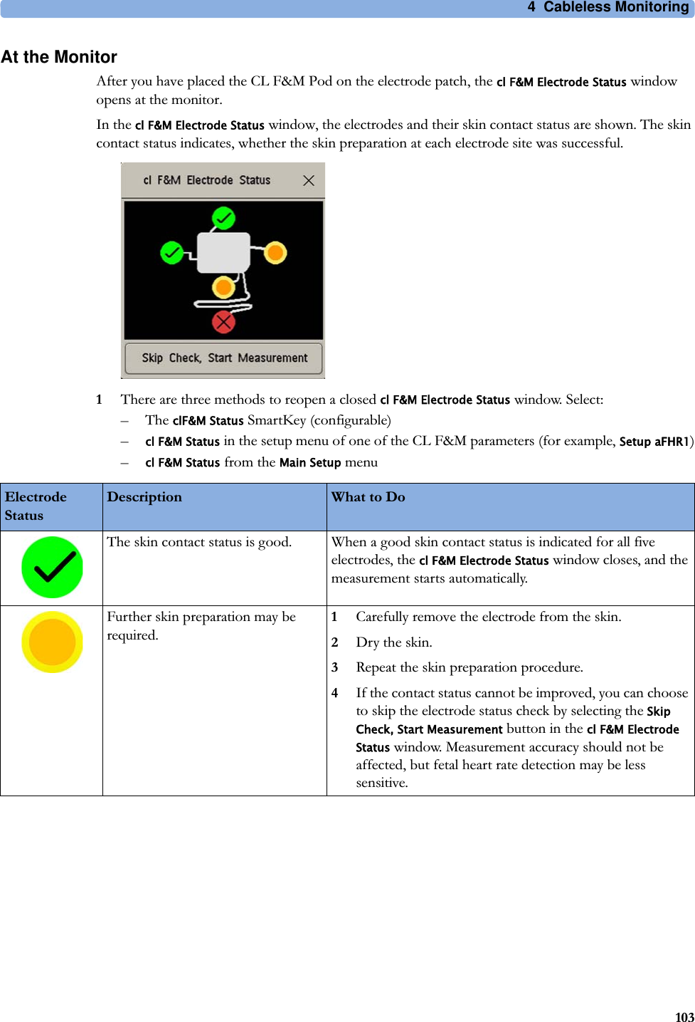
Philips Medical Systems North America SRRFMPBV1 Device for monitoring fetal and maternal heartrate and uterin activity User Manual ait fm manual
Philips Medical Systems North America Co. Device for monitoring fetal and maternal heartrate and uterin activity ait fm manual
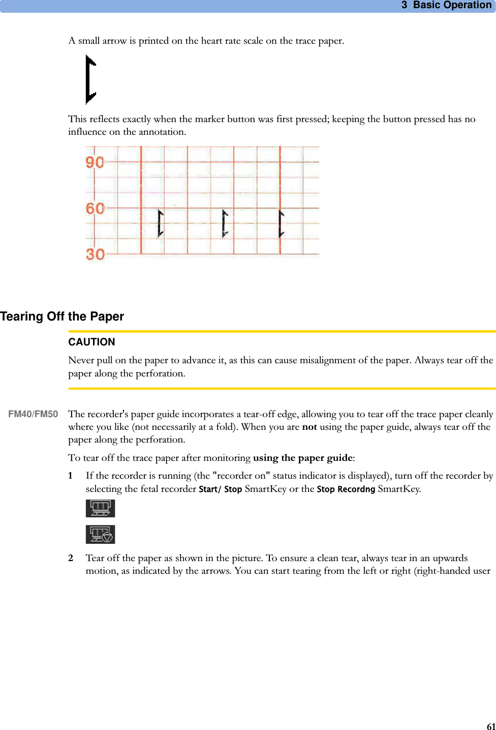
User manual
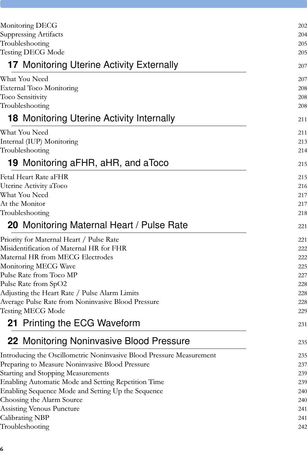
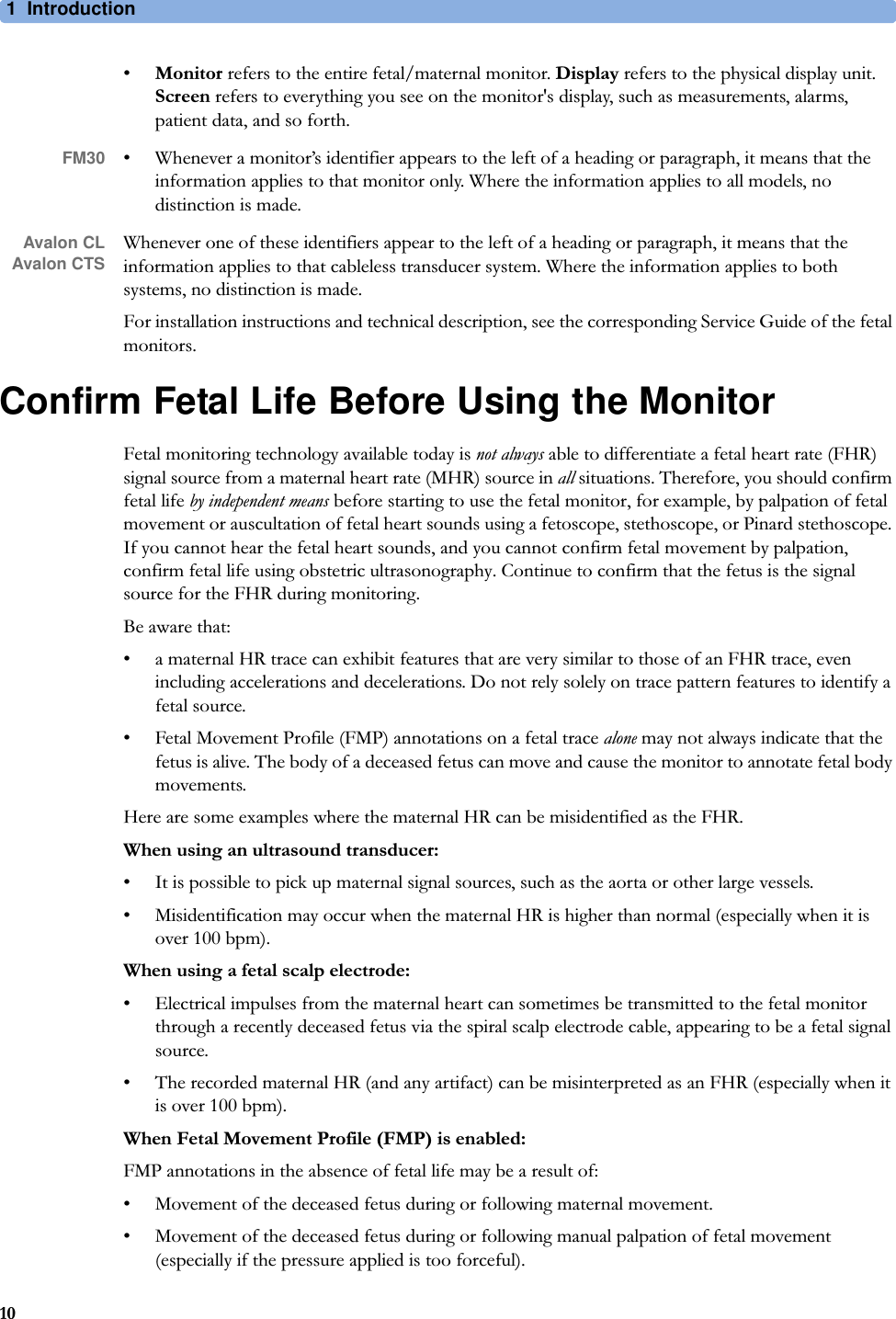
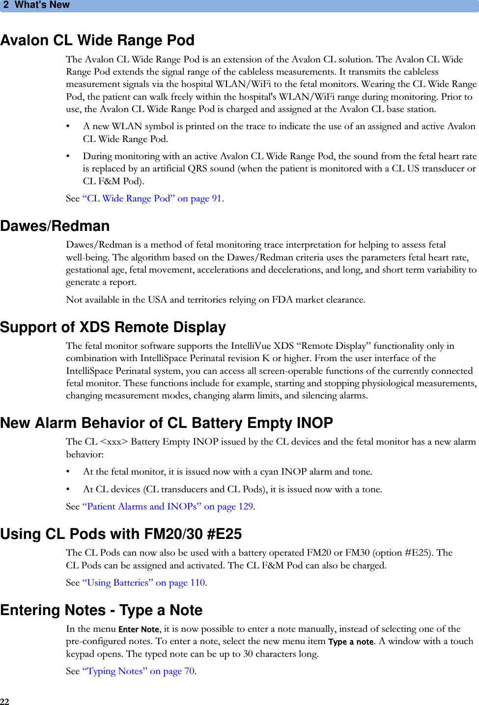
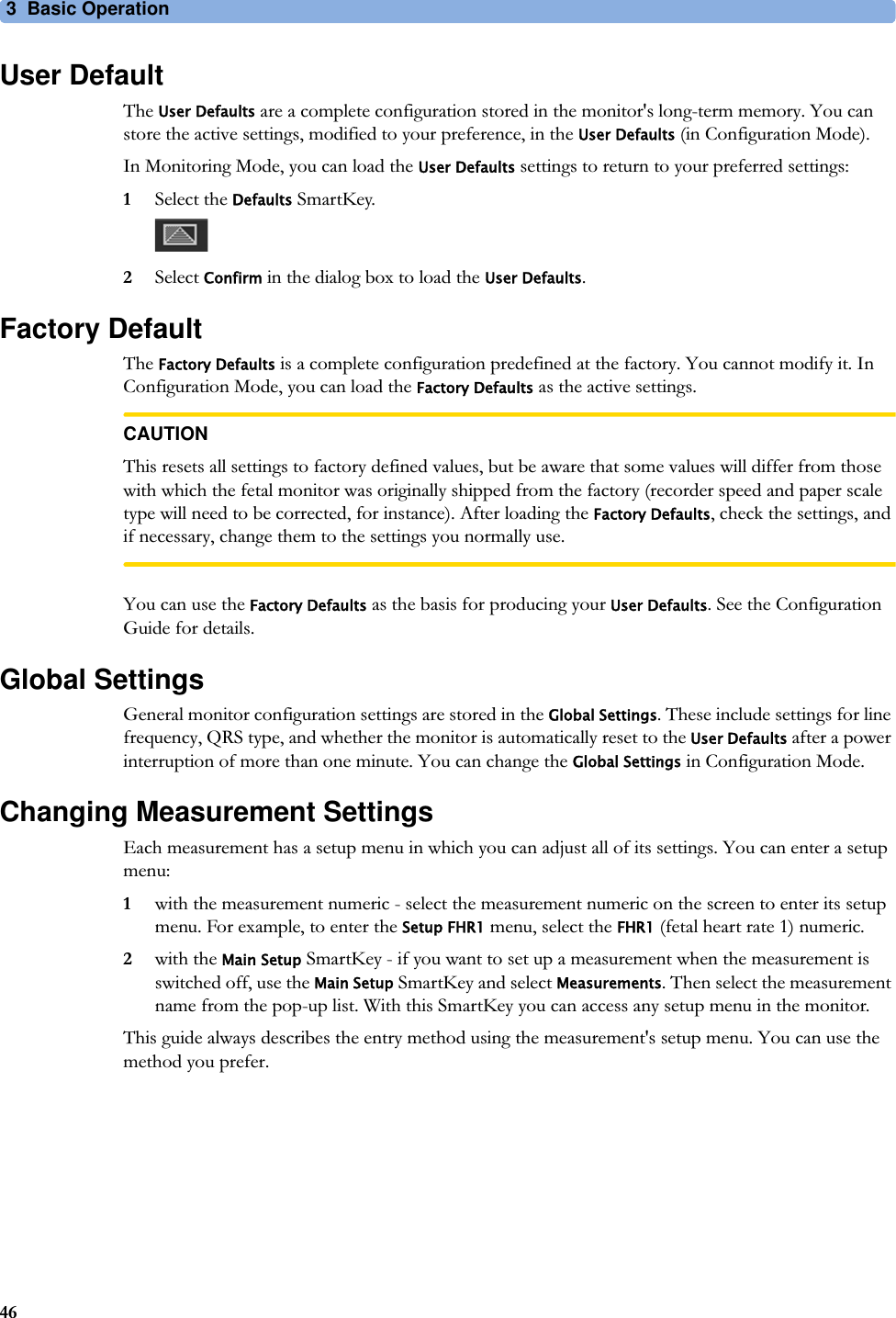
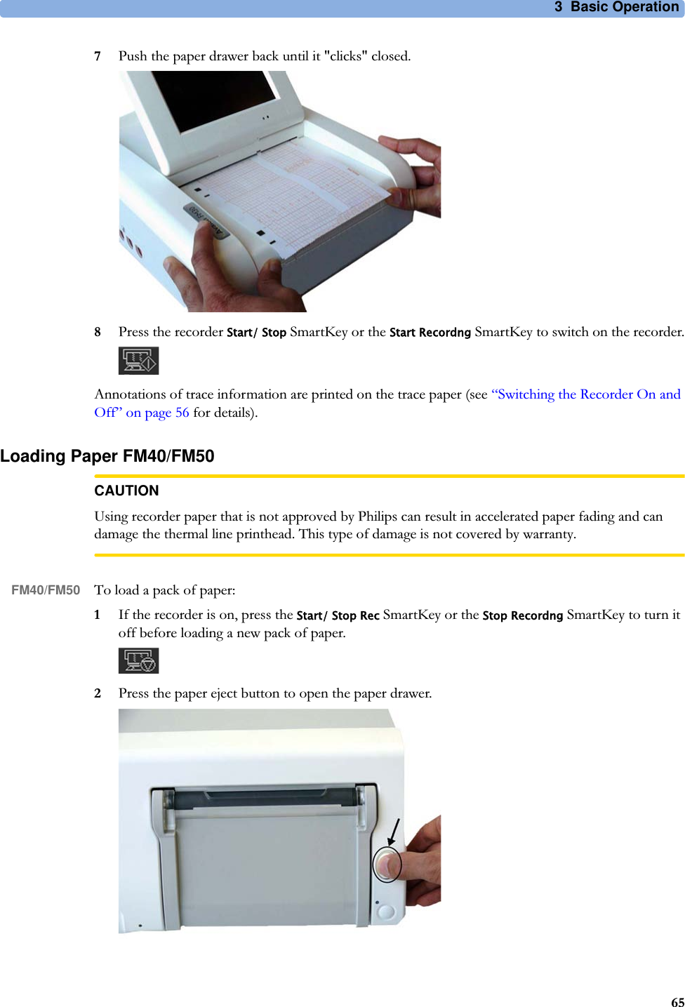
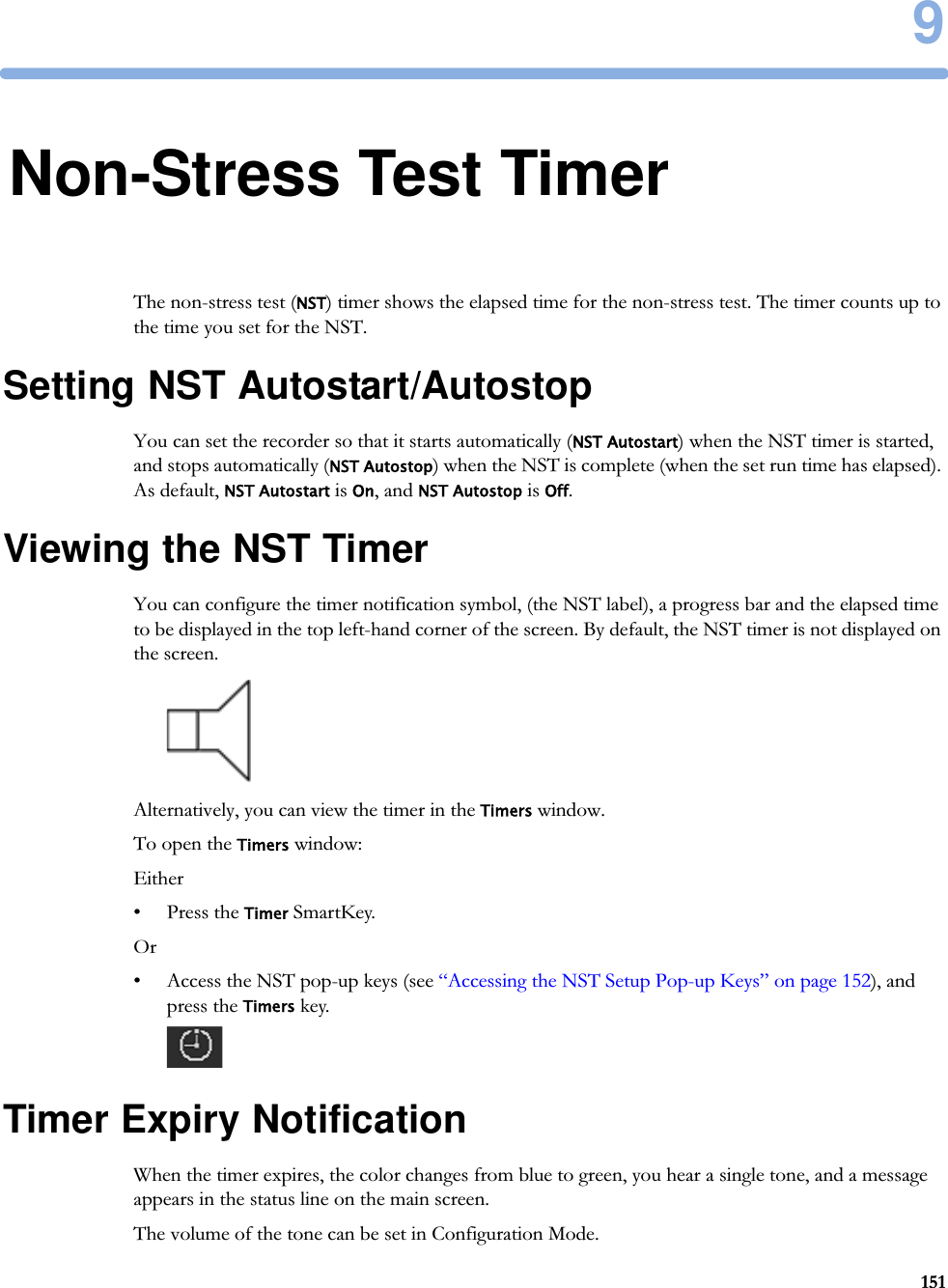
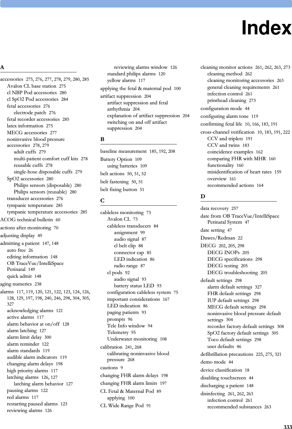
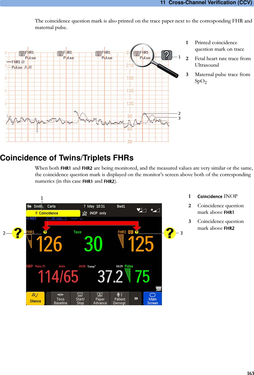
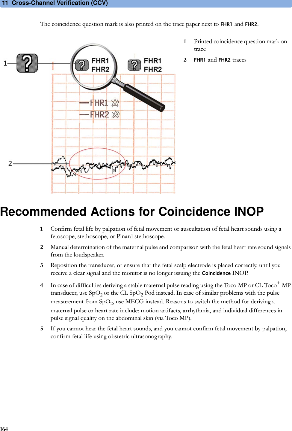
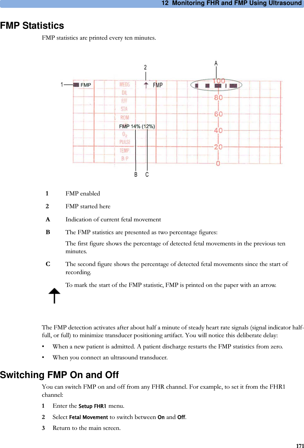
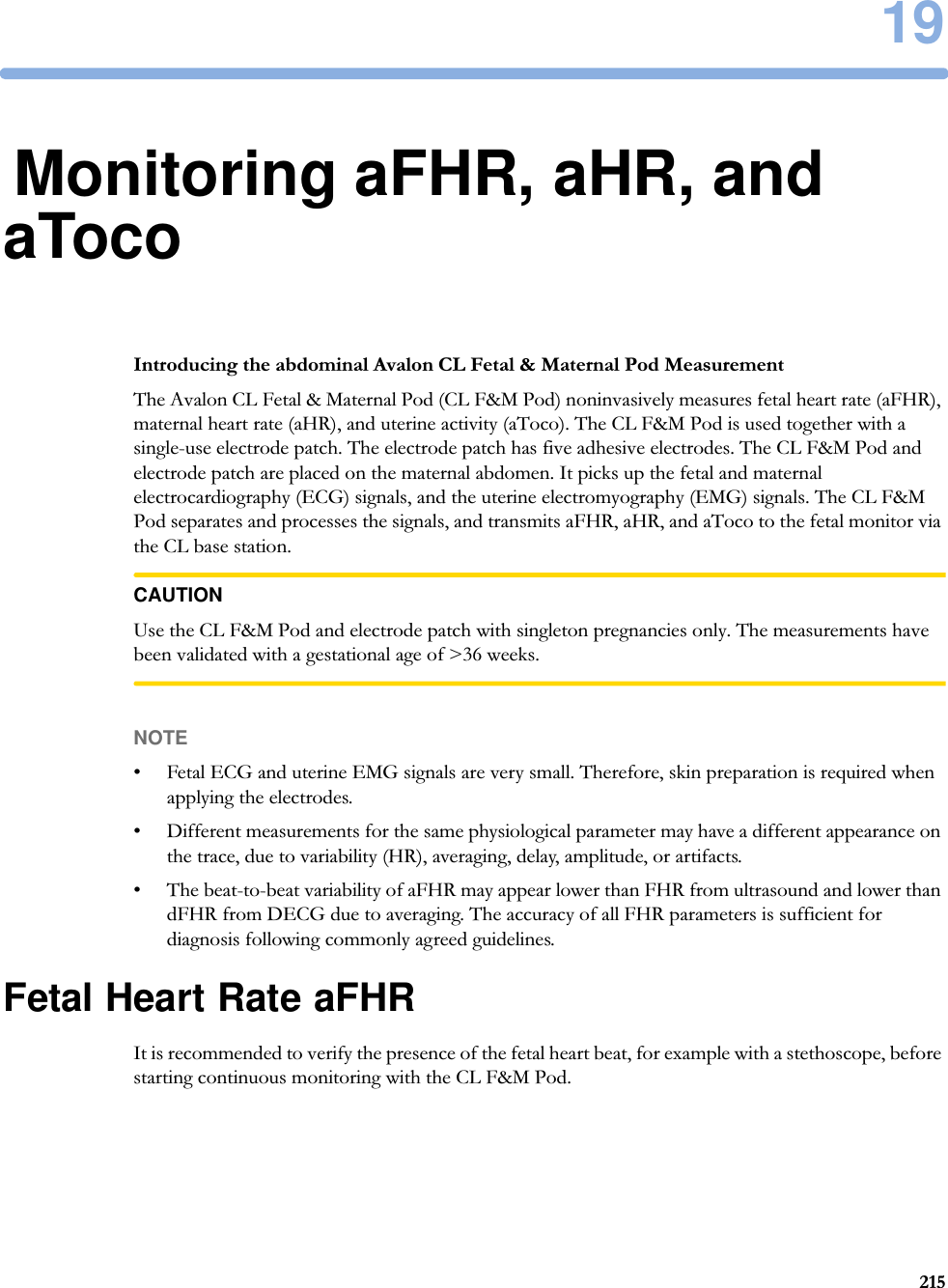
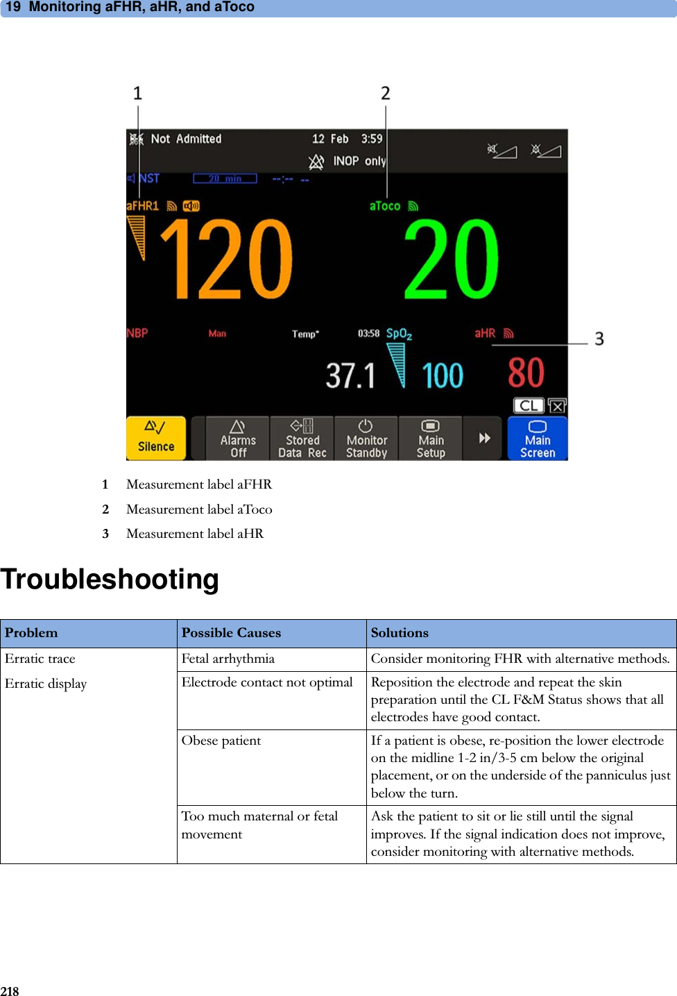
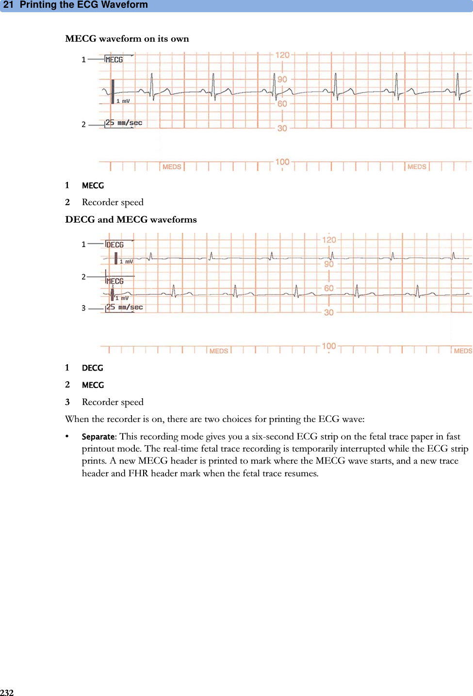
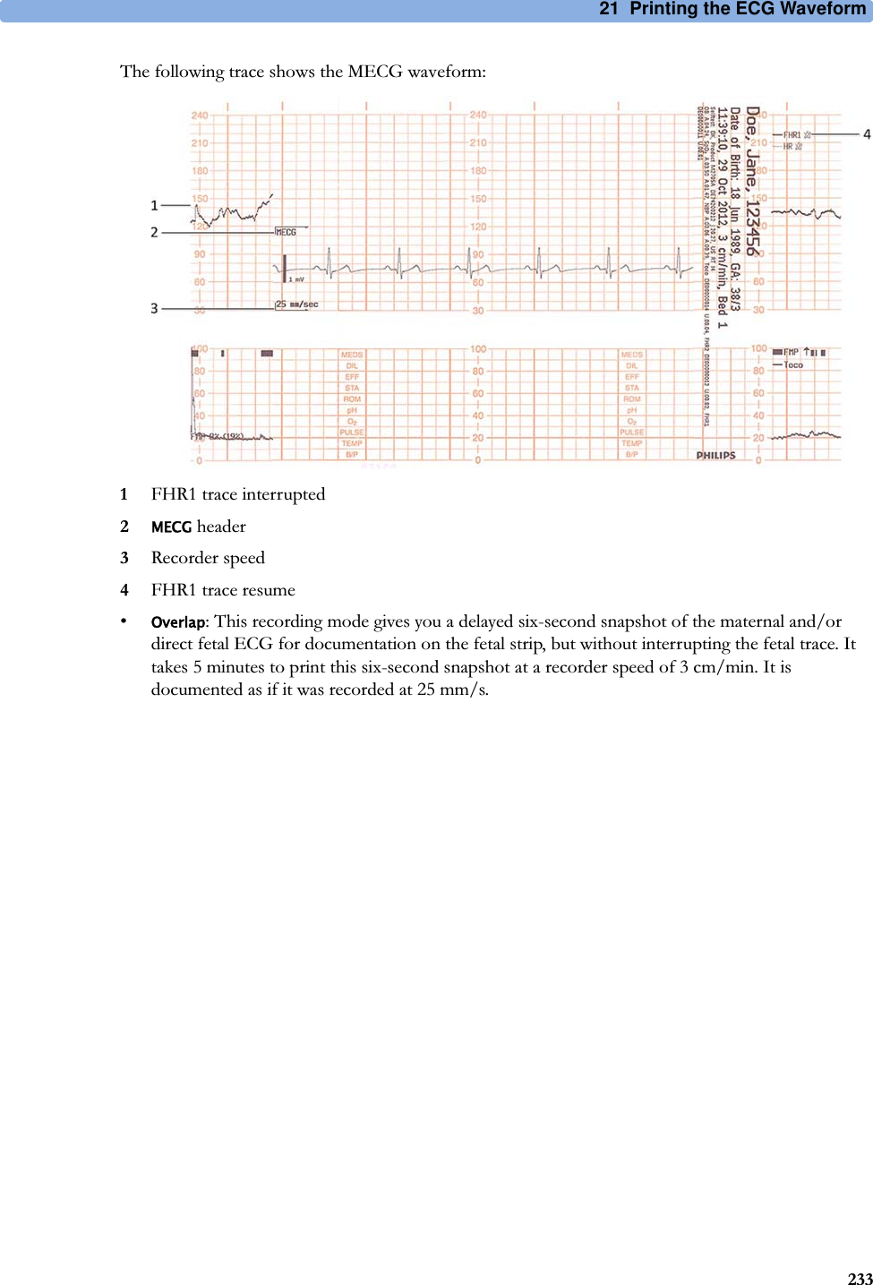
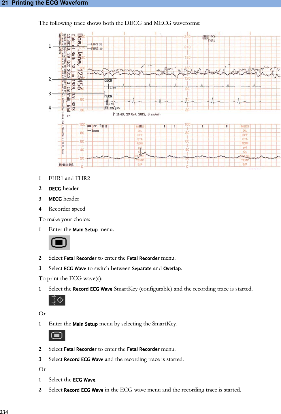
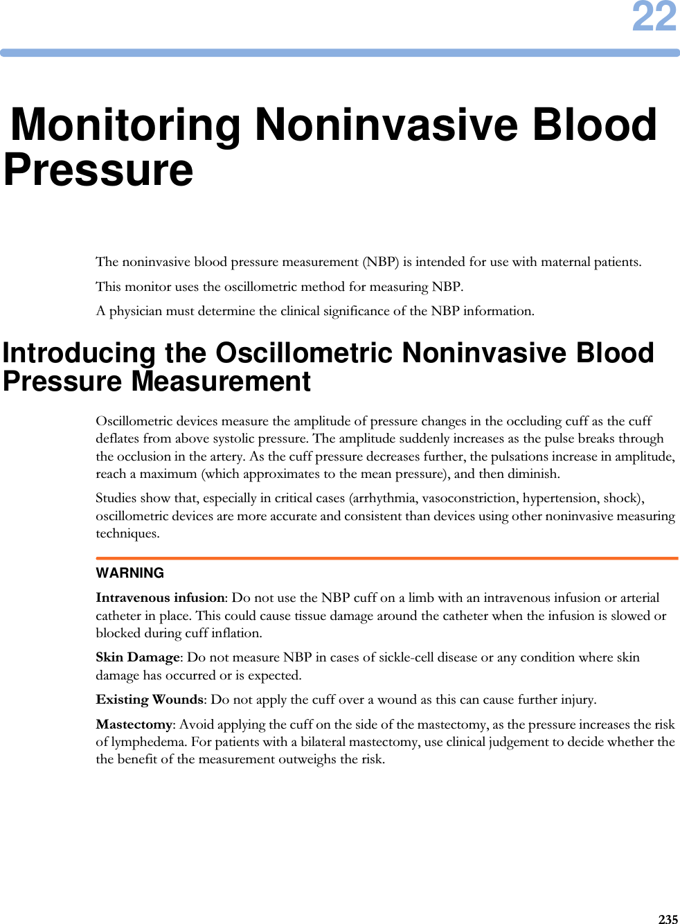
![10 Non-Stress Test Report1544Set your configuration options.Select from:•NST Analysis choose from On or Off.This switches the report feature on or off. This is linked to the NST timer. Both must be set to On for the NST report to function.•Report Recording choose from:–Manual - press the Record Report pop-up key to trigger a manual request.–After Recorder Stop - report is recorded as soon as recorder becomes idle.–Immediately - if a realtime recording is running, the monitor pauses it. The recording is continued after the report has been recorded.Average short term variability (STV) value is documented in [bpm] and [ms] if STV is configured as part of the NST Report. This parameter is not considered as reassuring criteria.NST Report Status WindowThe NST Report window displays a detailed overview of the current NST status for any available ultrasound fetal heart rate measurement. You can see:• NST Status - whether it is ready, ongoing, or the time and date at which it was stopped, or at which it was finished.• Elapsed time - the time that has elapsed since the NST began.• Accelerations - the number of FHR accelerations detected so far.• Baseline - the average baseline value.• Variability - the average variability value.• Short Term Variability - the current short term variability (STV) value.• Decelerations - the number of FHR decelerations detected so far.• FHR Availability - current statistical FHR availability value.• Sinusoidal - the current status of sinusoidal rhythm detection.For criteria not yet met, a white arrow symbol marks the overall status on the top line, and also appears against every criterion not yet met. A yellow symbol indicates detection of severe or prolonged decelerations.The pop-up keys let you perform the following actions:•FHR1, FHR2, FHR3 - switch to the window showing the current NST status for the fetal heart rate.•Record Report - print the NST Report on paper.•Record Trace - record the trace episode that belongs to the current report. Depending on device usage, the trace recording might be incomplete.•Setup - open the Setup NST Report window.](https://usermanual.wiki/Philips-Medical-Systems-North-America/SRRFMPBV1/User-Guide-3554569-Page-154.png)


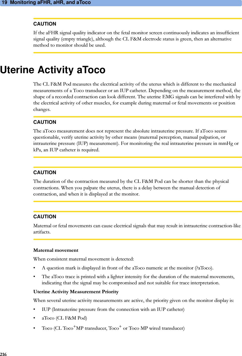
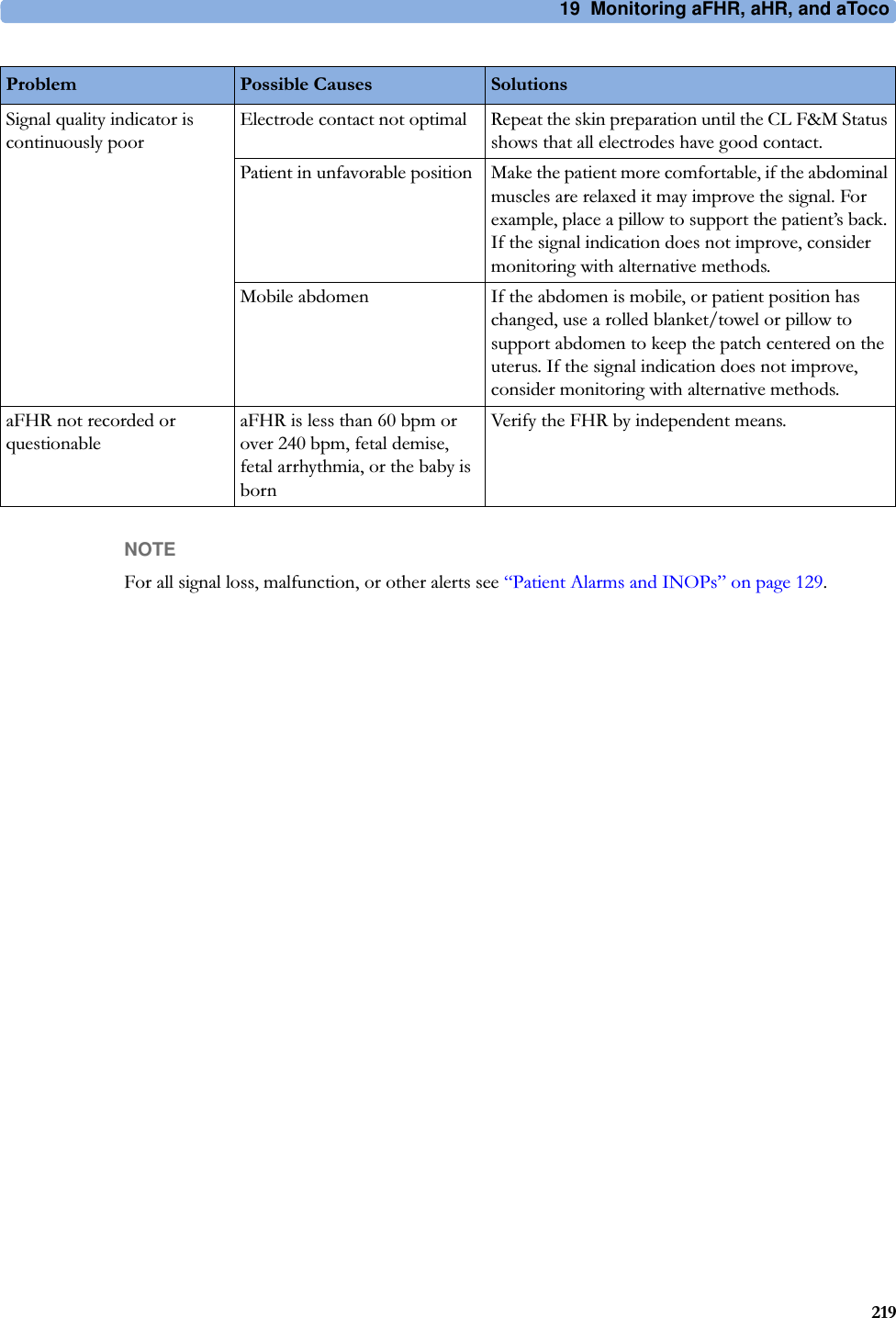


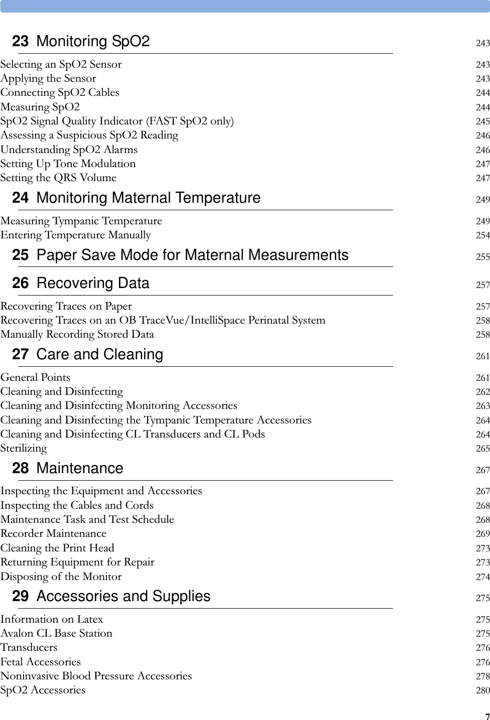
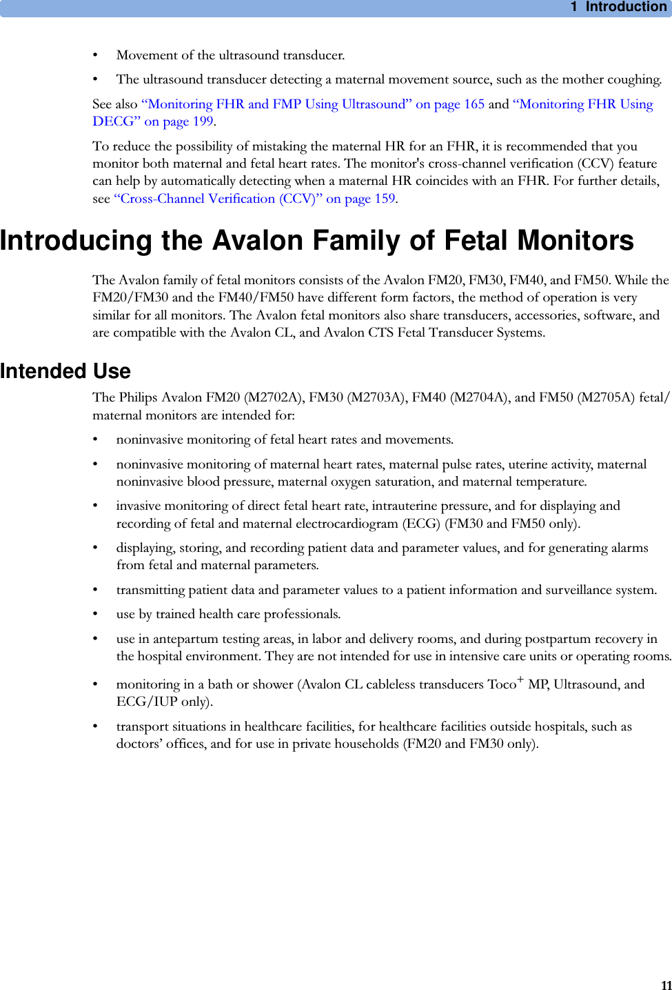
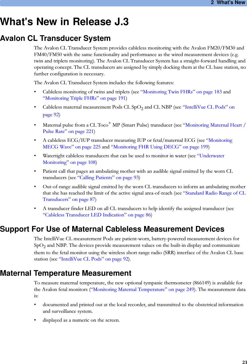
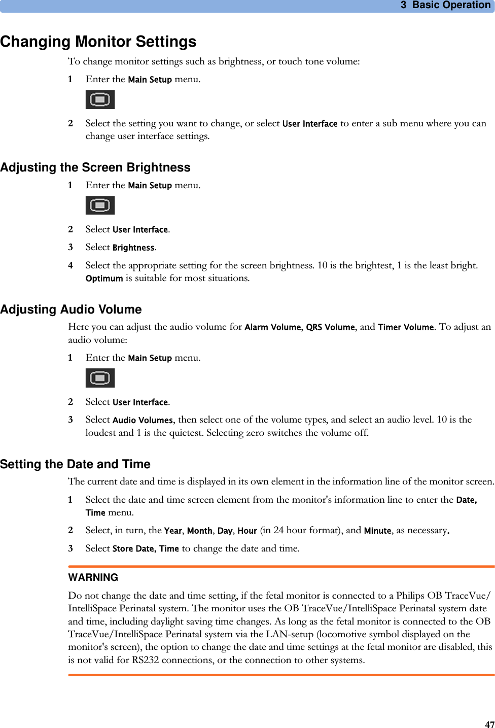
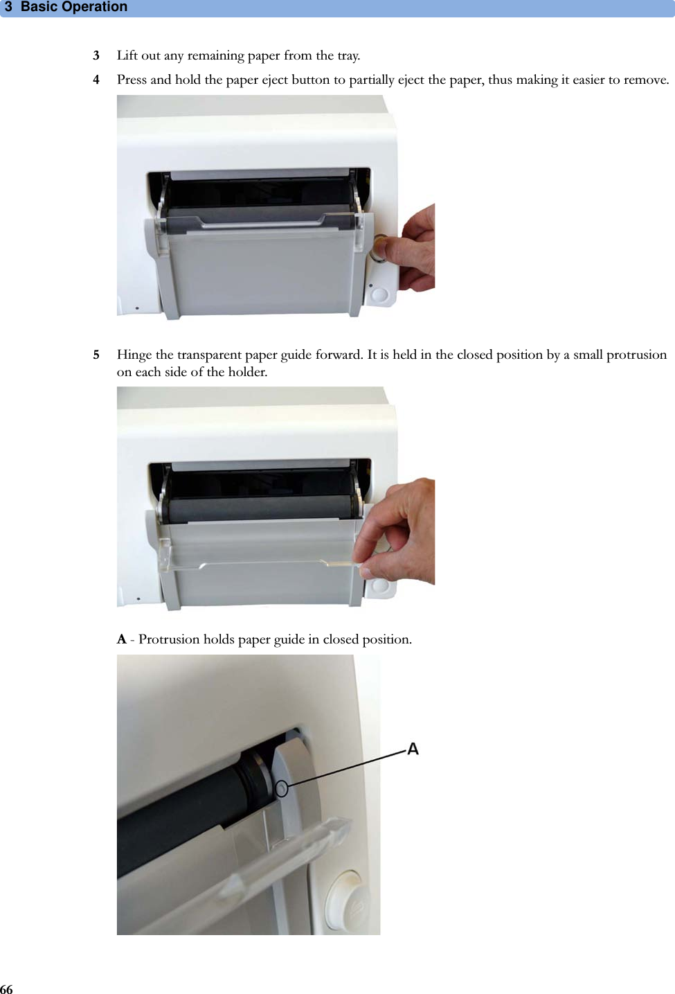
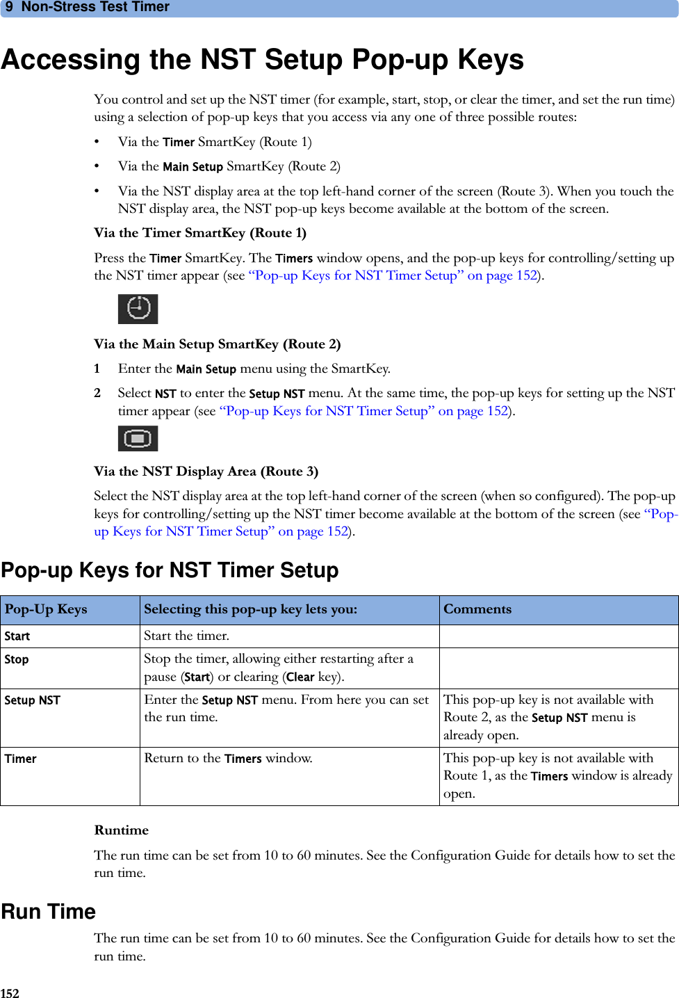
![30 Specifications and Standards Compliance293Interface SpecificationsFetal Monitors1 The power loss indication functionality of the Nurse Call Relay board is not supported with fetal monitors.Interface SpecificationsNetwork Standard 100-Base-TX (IEEE 802.3 Clause 25)Connector RJ45 (8 pin)Isolation Basic isolation (reference voltage: 250 V; test voltage: 1500 V)MIB/RS232 Standard IEEE 1073-3.2-2000Connectors RJ45 (8 pin)Mode Software-controllable BCC (RxD/TxD cross over) or DCC (RxD/TxD straight through)Power 5 V ±5%, 100 mA (max.)Isolation Basic isolation (reference voltage: 250 V; test voltage: 1500 V)USB Interface Standard USB 2.0 full-speed (embedded host)Connectors USB series "Standard A" receptaclePower Low power port 4.4V min; max. load for all ports together 500 mAIsolation noneRS232 (Standard) Connectors RJ45 (8 pin)Power noneIsolation Basic isolation (reference voltage: 250 V; test voltage: 1500 V)RS232 (Independent display interface option)Connectors RJ45 (8 pin)Power noneIsolation noneFlexible Nurse Call Relay1Connectors 20 pin MDR (Mini D-Ribbon), active open and closed contactsContact 100 mA, 24 V DCIsolation Basic isolation (reference voltage: 250 V; test voltage: 1500 V)Delay <[Configured Latency +0.5] sec](https://usermanual.wiki/Philips-Medical-Systems-North-America/SRRFMPBV1/User-Guide-3554569-Page-293.png)
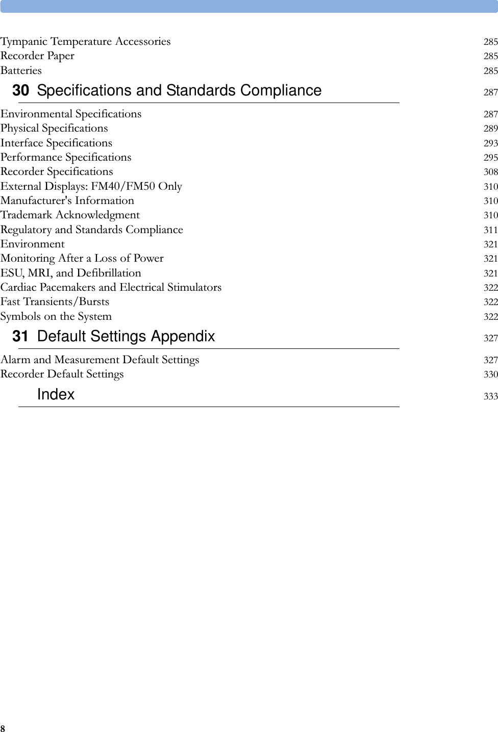
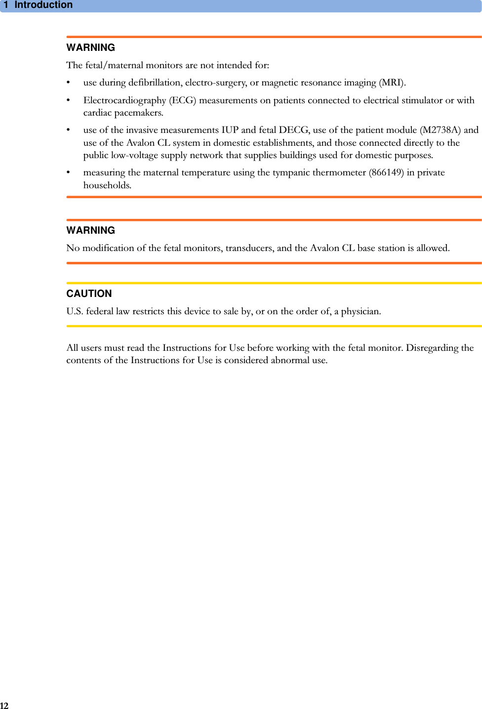
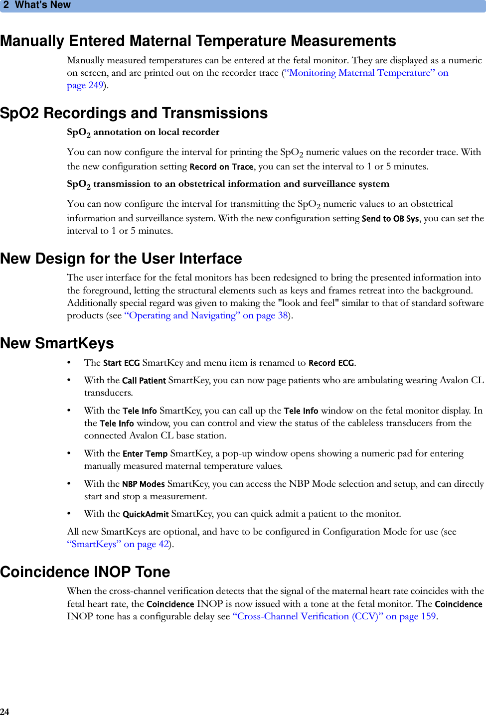
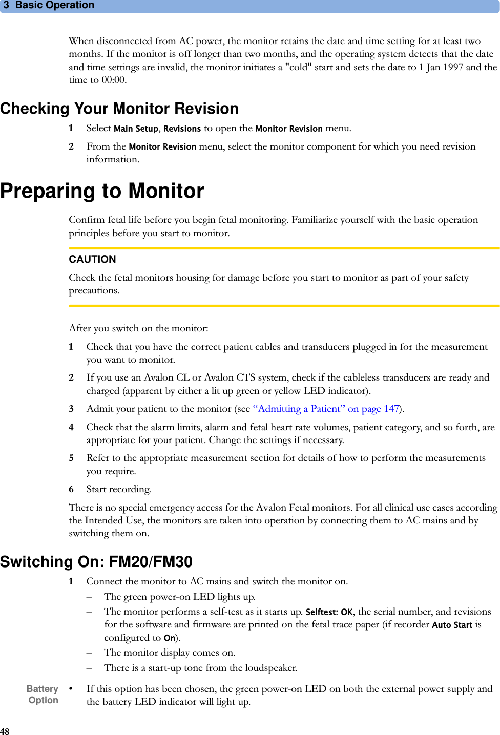
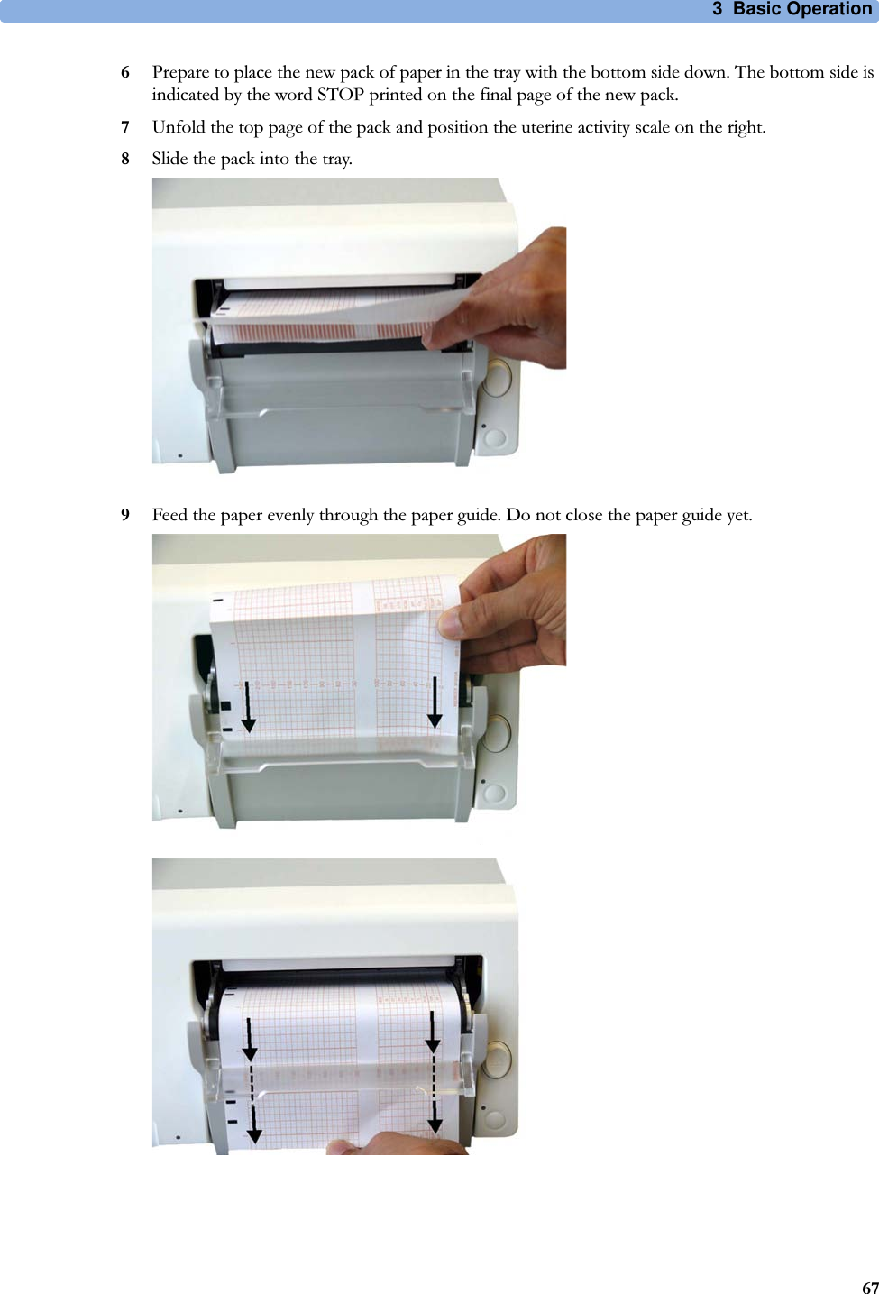
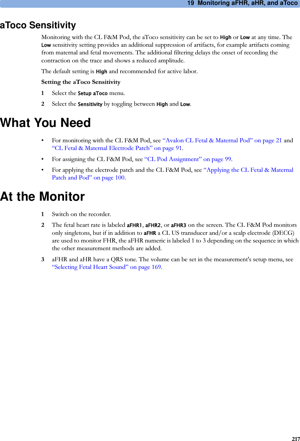
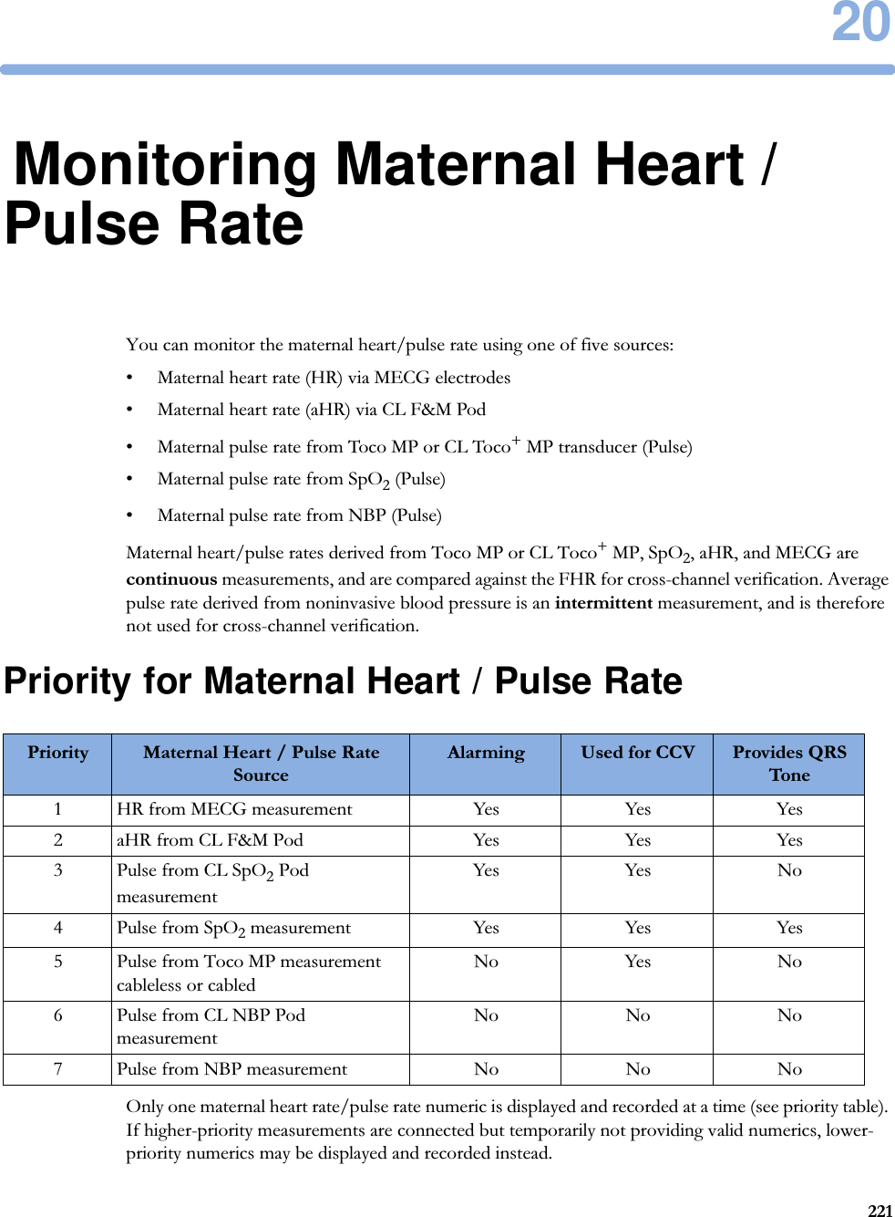
![30 Specifications and Standards Compliance325Association Of Radio Industries And Businesses T108 (Avalon CL frequency band used e.g. in Japan)Wireless Medical Telemetry Service (Avalon CL frequency band used e.g. in North America)Symbol DescriptionIC-ID (Industry Canada ID)One IC-ID labeling for each built in radio: OBR, SRR Japanese Radio marking: Radio mark + [R]-symbol + IDTaiwan Radio Label (NCC Logo) + ID Korea radio mark: KC logo, KCC ID number, and Conformity assessment information](https://usermanual.wiki/Philips-Medical-Systems-North-America/SRRFMPBV1/User-Guide-3554569-Page-325.png)