Philips Medical Systems North America SRRFMPBV1 Device for monitoring fetal and maternal heartrate and uterin activity User Manual ait fm manual
Philips Medical Systems North America Co. Device for monitoring fetal and maternal heartrate and uterin activity ait fm manual
User manual

Instructions for Use
Avalon Fetal Monitor
FM20/30, FM40/50, Avalon CL
Release L.3 with Software Revision L.3x.xx
Patient Monitoring

3
1Table of Contents
1Introduction 9
Who this Book is For 9
Confirm Fetal Life Before Using the Monitor 10
Introducing the Avalon Family of Fetal Monitors 11
2What's New 21
What's New in Release L.3 21
What's New in Release J.3 23
3Basic Operation 27
Supported Measurements 28
Avalon FM20 and FM30 29
Avalon FM40 and FM50 30
Getting to Know Your Avalon FM20/FM30 31
Getting to Know Your Avalon FM40/FM50 34
Connecting the Monitor to AC Mains 36
Wired Transducers 36
Operating and Navigating 38
Operating Modes 44
Automatic Screen Layouts 45
Settings 45
Preparing to Monitor 48
After Monitoring 70
Switching the Monitor to the Standby Screen 71
Disconnecting from Power 71
Power On/Power Off Behavior 71
Monitoring After a Power Failure 72
Troubleshooting 72
4Cableless Monitoring 73
Avalon CL Transducer System 73
Basics of Cableless Systems 74
Twins and Triplets Support 75
Configuration of Cableless Systems 75
Getting to Know Your Avalon CL 76
Cableless Transducers 84
CL Pods 89
Calling Patients 93
Telemetry 94
Preparing to Monitor Cablelessly 100

4
Battery Lifetime Management 106
Patient Transport Within the Hospital 107
Underwater Monitoring 108
5FM20/30 Battery Option 109
External Power Supply M8023A 109
Using Batteries 110
Optimizing Battery Performance 113
Storing the Battery 115
Cableless Monitoring with FM20/30 Battery Option 116
Patient Transport Within the Hospital 116
6Alarms 117
Alarm Mode 118
Nurse Call Systems 118
Visual Alarm Indicators 119
Audible Alarm Indicators 119
Acknowledging Alarms 121
Acknowledging Disconnect INOPs 121
Alarm Reminder 122
Pausing or Switching Off Alarms 122
Alarm Limits 124
Reviewing Alarms 126
Latching Alarms 126
Testing Alarms 128
Alarm Behavior at Power On 128
7Patient Alarms and INOPs 129
Alarm Messages 129
Technical Alarm Messages (INOPs) 132
8Admitting and Discharging 147
Admit/Discharge on the Monitor 147
New Patient Check 149
OB TraceVue/IntelliSpace Perinatal 149
9Non-Stress Test Timer 151
Setting NST Autostart/Autostop 151
Viewing the NST Timer 151
Timer Expiry Notification 151
Accessing the NST Setup Pop-up Keys 152
10 Non-Stress Test Report 153
Setting Up an NST Report 153
NST Report Status Window 154
NST Criteria 157

5
11 Cross-Channel Verification (CCV) 159
Misidentification of Heart Rates 159
Cross-Channel Verification Functionality 160
Overview of Cross-Channel Comparisons 161
Coincidence Examples 162
Recommended Actions for Coincidence INOP 164
12 Monitoring FHR and FMP Using Ultrasound 165
Technical Description 165
Limitations of the Technology 166
Misidentification of Maternal HR as FHR 166
What You Need 166
Cableless Monitoring - Important Considerations 167
Preparing to Monitor 168
Selecting Fetal Heart Sound 169
Changing the Fetal Heart Sound Volume 170
Fetal Movement Profile 170
Troubleshooting 172
Additional Information 173
13 Monitoring Twin FHRs 183
Important Considerations 183
Monitoring Twins Externally 184
Monitoring Twins Internally 185
Separating FHR Traces 185
Troubleshooting 189
14 Monitoring Triple FHRs 191
Important Considerations 191
Monitoring Triplets 192
Separating FHR Traces 192
"Standard" Separation Order 193
"Classic" Separation Order 194
Switching Trace Separation On and Off 195
When Trace Separation is On 195
When Trace Separation is Off 195
Troubleshooting 196
15 Fetal Heart Rate Alarms 197
Changing Alarm Settings 197
Changing Signal Loss Delay 198
16 Monitoring FHR Using DECG 199
Misidentification of Maternal HR as FHR 199
What You Need 200
Making Connections 202

6
Monitoring DECG 202
Suppressing Artifacts 204
Troubleshooting 205
Testing DECG Mode 205
17 Monitoring Uterine Activity Externally 207
What You Need 207
External Toco Monitoring 208
Toco Sensitivity 208
Troubleshooting 208
18 Monitoring Uterine Activity Internally 211
What You Need 211
Internal (IUP) Monitoring 213
Troubleshooting 214
19 Monitoring aFHR, aHR, and aToco 215
Fetal Heart Rate aFHR 215
Uterine Activity aToco 216
What You Need 217
At the Monitor 217
Troubleshooting 218
20 Monitoring Maternal Heart / Pulse Rate 221
Priority for Maternal Heart / Pulse Rate 221
Misidentification of Maternal HR for FHR 222
Maternal HR from MECG Electrodes 222
Monitoring MECG Wave 225
Pulse Rate from Toco MP 227
Pulse Rate from SpO2 228
Adjusting the Heart Rate / Pulse Alarm Limits 228
Average Pulse Rate from Noninvasive Blood Pressure 228
Testing MECG Mode 229
21 Printing the ECG Waveform 231
22 Monitoring Noninvasive Blood Pressure 235
Introducing the Oscillometric Noninvasive Blood Pressure Measurement 235
Preparing to Measure Noninvasive Blood Pressure 237
Starting and Stopping Measurements 239
Enabling Automatic Mode and Setting Repetition Time 239
Enabling Sequence Mode and Setting Up the Sequence 240
Choosing the Alarm Source 240
Assisting Venous Puncture 241
Calibrating NBP 241
Troubleshooting 242

7
23 Monitoring SpO2 243
Selecting an SpO2 Sensor 243
Applying the Sensor 243
Connecting SpO2 Cables 244
Measuring SpO2 244
SpO2 Signal Quality Indicator (FAST SpO2 only) 245
Assessing a Suspicious SpO2 Reading 246
Understanding SpO2 Alarms 246
Setting Up Tone Modulation 247
Setting the QRS Volume 247
24 Monitoring Maternal Temperature 249
Measuring Tympanic Temperature 249
Entering Temperature Manually 254
25 Paper Save Mode for Maternal Measurements 255
26 Recovering Data 257
Recovering Traces on Paper 257
Recovering Traces on an OB TraceVue/IntelliSpace Perinatal System 258
Manually Recording Stored Data 258
27 Care and Cleaning 261
General Points 261
Cleaning and Disinfecting 262
Cleaning and Disinfecting Monitoring Accessories 263
Cleaning and Disinfecting the Tympanic Temperature Accessories 264
Cleaning and Disinfecting CL Transducers and CL Pods 264
Sterilizing 265
28 Maintenance 267
Inspecting the Equipment and Accessories 267
Inspecting the Cables and Cords 268
Maintenance Task and Test Schedule 268
Recorder Maintenance 269
Cleaning the Print Head 273
Returning Equipment for Repair 273
Disposing of the Monitor 274
29 Accessories and Supplies 275
Information on Latex 275
Avalon CL Base Station 275
Transducers 276
Fetal Accessories 276
Noninvasive Blood Pressure Accessories 278
SpO2 Accessories 280

8
Tympanic Temperature Accessories 285
Recorder Paper 285
Batteries 285
30 Specifications and Standards Compliance 287
Environmental Specifications 287
Physical Specifications 289
Interface Specifications 293
Performance Specifications 295
Recorder Specifications 308
External Displays: FM40/FM50 Only 310
Manufacturer's Information 310
Trademark Acknowledgment 310
Regulatory and Standards Compliance 311
Environment 321
Monitoring After a Loss of Power 321
ESU, MRI, and Defibrillation 321
Cardiac Pacemakers and Electrical Stimulators 322
Fast Transients/Bursts 322
Symbols on the System 322
31 Default Settings Appendix 327
Alarm and Measurement Default Settings 327
Recorder Default Settings 330
Index 333

1
9
1Introduction
Who this Book is For
This book is for trained healthcare professionals using the Avalon FM20, FM30, FM40, and FM50
fetal/maternal monitors, and the Avalon CL Transducer System. It describes how to set up and use the
monitor and transducers. Familiarize yourself with all instructions including warnings and cautions
before starting to monitor patients. Read and keep the Instructions for Use that come with any
accessories, as these contain important information about application, care, and cleaning that is not
repeated in this book.
If you have received this Instruction for Use because your fetal monitor has been upgraded to a newer
software version L.3, be aware that the standards compliance information contained in the
Instructions for Use for L.3 does not apply to your fetal monitor. Refer to your original Instructions
for Use for standards compliance information.
You should be:
• Trained in the use of fetal heart rate (FHR) monitors.
• Trained in the interpretation of FHR traces.
• Familiar with using medical devices and with standard fetal monitoring procedures.
For information on how to configure and service the monitor, see the Configuration Guide and the
Service Guides, or contact your authorized service provider.
Your monitor may not have all of the features and options described in this guide. The exact
appearance of the monitor may differ slightly from that shown in the illustrations.
This guide may contain descriptions of functionality and features that are not implemented in the
equipment currently shipped to Japan and/or of products that are not currently sold in Japan due to
limitations and restrictions under the applicable local laws and regulations in Japan. Please contact your
local sales representative and/or Philips Customer Support for details.
In this guide:
•A warning alerts you to a potential serious outcome, adverse event, or safety hazard. Failure to
observe a warning may result in death or serious injury to the user or patient.
•A caution alerts you to where special care is necessary for the safe and effective use of the
product. Failure to observe a caution may result in:
– minor or moderate personal injury,
– damage to the product or other property,
– possibly in a remote risk of more serious injury.

1 Introduction
10
•Monitor refers to the entire fetal/maternal monitor. Display refers to the physical display unit.
Screen refers to everything you see on the monitor's display, such as measurements, alarms,
patient data, and so forth.
FM30 • Whenever a monitor’s identifier appears to the left of a heading or paragraph, it means that the
information applies to that monitor only. Where the information applies to all models, no
distinction is made.
Avalon CL
Avalon CTS Whenever one of these identifiers appear to the left of a heading or paragraph, it means that the
information applies to that cableless transducer system. Where the information applies to both
systems, no distinction is made.
For installation instructions and technical description, see the corresponding Service Guide of the fetal
monitors.
Confirm Fetal Life Before Using the Monitor
Fetal monitoring technology available today is not always able to differentiate a fetal heart rate (FHR)
signal source from a maternal heart rate (MHR) source in all situations. Therefore, you should confirm
fetal life by independent means before starting to use the fetal monitor, for example, by palpation of fetal
movement or auscultation of fetal heart sounds using a fetoscope, stethoscope, or Pinard stethoscope.
If you cannot hear the fetal heart sounds, and you cannot confirm fetal movement by palpation,
confirm fetal life using obstetric ultrasonography. Continue to confirm that the fetus is the signal
source for the FHR during monitoring.
Be aware that:
• a maternal HR trace can exhibit features that are very similar to those of an FHR trace, even
including accelerations and decelerations. Do not rely solely on trace pattern features to identify a
fetal source.
• Fetal Movement Profile (FMP) annotations on a fetal trace alone may not always indicate that the
fetus is alive. The body of a deceased fetus can move and cause the monitor to annotate fetal body
movements.
Here are some examples where the maternal HR can be misidentified as the FHR.
When using an ultrasound transducer:
• It is possible to pick up maternal signal sources, such as the aorta or other large vessels.
• Misidentification may occur when the maternal HR is higher than normal (especially when it is
over 100 bpm).
When using a fetal scalp electrode:
• Electrical impulses from the maternal heart can sometimes be transmitted to the fetal monitor
through a recently deceased fetus via the spiral scalp electrode cable, appearing to be a fetal signal
source.
• The recorded maternal HR (and any artifact) can be misinterpreted as an FHR (especially when it
is over 100 bpm).
When Fetal Movement Profile (FMP) is enabled:
FMP annotations in the absence of fetal life may be a result of:
• Movement of the deceased fetus during or following maternal movement.
• Movement of the deceased fetus during or following manual palpation of fetal movement
(especially if the pressure applied is too forceful).

1 Introduction
11
• Movement of the ultrasound transducer.
• The ultrasound transducer detecting a maternal movement source, such as the mother coughing.
See also “Monitoring FHR and FMP Using Ultrasound” on page 165 and “Monitoring FHR Using
DECG” on page 199.
To reduce the possibility of mistaking the maternal HR for an FHR, it is recommended that you
monitor both maternal and fetal heart rates. The monitor's cross-channel verification (CCV) feature
can help by automatically detecting when a maternal HR coincides with an FHR. For further details,
see “Cross-Channel Verification (CCV)” on page 159.
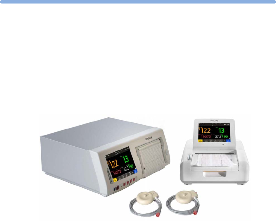
Introducing the Avalon Family of Fetal Monitors
The Avalon family of fetal monitors consists of the Avalon FM20, FM30, FM40, and FM50. While the
FM20/FM30 and the FM40/FM50 have different form factors, the method of operation is very
similar for all monitors. The Avalon fetal monitors also share transducers, accessories, software, and
are compatible with the Avalon CL, and Avalon CTS Fetal Transducer Systems.
Intended Use
The Philips Avalon FM20 (M2702A), FM30 (M2703A), FM40 (M2704A), and FM50 (M2705A) fetal/
maternal monitors are intended for:
• noninvasive monitoring of fetal heart rates and movements.
• noninvasive monitoring of maternal heart rates, maternal pulse rates, uterine activity, maternal
noninvasive blood pressure, maternal oxygen saturation, and maternal temperature.
• invasive monitoring of direct fetal heart rate, intrauterine pressure, and for displaying and
recording of fetal and maternal electrocardiogram (ECG) (FM30 and FM50 only).
• displaying, storing, and recording patient data and parameter values, and for generating alarms
from fetal and maternal parameters.
• transmitting patient data and parameter values to a patient information and surveillance system.
• use by trained health care professionals.
• use in antepartum testing areas, in labor and delivery rooms, and during postpartum recovery in
the hospital environment. They are not intended for use in intensive care units or operating rooms.
• monitoring in a bath or shower (Avalon CL cableless transducers Toco+ MP, Ultrasound, and
ECG/IUP only).
• transport situations in healthcare facilities, for healthcare facilities outside hospitals, such as
doctors’ offices, and for use in private households (FM20 and FM30 only).

1 Introduction
12
WARNING
The fetal/maternal monitors are not intended for:
• use during defibrillation, electro-surgery, or magnetic resonance imaging (MRI).
• Electrocardiography (ECG) measurements on patients connected to electrical stimulator or with
cardiac pacemakers.
• use of the invasive measurements IUP and fetal DECG, use of the patient module (M2738A) and
use of the Avalon CL system in domestic establishments, and those connected directly to the
public low-voltage supply network that supplies buildings used for domestic purposes.
• measuring the maternal temperature using the tympanic thermometer (866149) in private
households.
WARNING
No modification of the fetal monitors, transducers, and the Avalon CL base station is allowed.
CAUTION
U.S. federal law restricts this device to sale by, or on the order of, a physician.
All users must read the Instructions for Use before working with the fetal monitor. Disregarding the
contents of the Instructions for Use is considered abnormal use.

1 Introduction
13
Indications for Use
Avalon Fetal/Maternal Monitor FM20
Indicated for use by trained health care professionals whenever there is a need for monitoring the
physiological parameters uterine activity, heart rate, oxygen saturation, noninvasive blood pressure,
pulse rate, and temperature of pregnant women, and the fetal heart rates of single fetuses, twins, and
triplets in labor and delivery rooms, in antepartum testing areas, in private households and during
transports in healthcare facilities.
Avalon Fetal/Maternal Monitor FM30
Indicated for use by trained health care professionals whenever there is a need for monitoring the
physiological parameters uterine activity, heart rate, electrocardiography (ECG), oxygen saturation,
noninvasive blood pressure, and pulse rate, and temperature of pregnant women, and the fetal heart
rates of single fetuses, twins, and triplets in labor and delivery rooms, in antepartum testing areas, in
private households and during transports in healthcare facilities.
Avalon Fetal/Maternal Monitor FM40
Indicated for use by trained health care professionals whenever there is a need for monitoring the
physiological parameters uterine activity, heart rate, oxygen saturation, noninvasive blood pressure,
and pulse rate, and temperature of pregnant women, and the fetal heart rates of single fetuses, twins,
and triplets in labor and delivery rooms and in antepartum testing areas.
Avalon Fetal/Maternal Monitor FM50
Indicated for use by trained health care professionals whenever there is a need for monitoring the
physiological parameters uterine activity, heart rate, electrocardiography (ECG), oxygen saturation,
noninvasive blood pressure, and pulse rate, and temperature of pregnant women, and the fetal heart
rates of single fetuses, twins, and triplets in labor and delivery rooms and in antepartum testing areas.
Safety Information
In this guide:
• A warning alerts you to a potential serious outcome, adverse event or safety hazard. Failure to
observe a warning may result in death or serious injury to the user or patient.
• A caution alerts you to where special care is necessary for the safe and effective use of the product.
Failure to observe a caution may result in minor or moderate personal injury or damage to the
product or other property, and possibly in a remote risk of more serious injury.

1 Introduction
14
Electrical Hazards
WARNING
Electrical shock hazard: Do not open the monitor housing. Refer all servicing to qualified service
personnel.
• Always use the supplied power cord with the earthed mains plug to connect to an earthed AC
mains socket. Never adapt the mains plug from the fetal monitor to fit an unearthed AC mains
socket.
• Do not use AC mains extension cords or multiple portable socket-outlets.
•FM20/FM30 only: The protective earth conductor is required for EMC purposes. It has no
protective function against electric shock. Double and/or reinforced insulation protects this
device against electric shock.
• Do not connect any devices that are not supported as part of a system.
• Any non-medical device placed and operated in the patient’s vicinity must be powered with an
approved isolation transformer that ensures mechanical fixing of the power cords, and covering of
any unused power outlets.
• The fetal/maternal monitor is NOT intended for use during defibrillation, electro-surgery, or
MRI. Remove all transducers, sensors, and accessories before performing electro-surgery,
defibrillation, or MRI, otherwise harm to the patient or the user can result.
• Do not touch the charging contacts for the cableless transducers at the Avalon CL base station
while you are touching the patient.
Leakage currents: If several items of equipment used to monitor a patient are interconnected, the
resulting leakage current may exceed allowable limits.
Radio Frequency Interference
WARNING
• Short range radio connections are subject to interruption due to interference from other radio
sources in the vicinity, including microwaves, bluetooth devices, WLAN devices (802.11b,g,n), and
cordless phones. Depending on the strength and duration of the interference, the interruption may
occur for an extended period. A loss of connection, due to moving out-of-range, interference, or
for other reasons, is indicated with a
No Host Monitoring
INOP (here the host is the fetal monitor)
on the IntelliVue CL NBP or CL SpO2 Pods, or a
No Host Monitoring
, or
cl NBP Disconnect
, or
cl
SpO Disconnect
INOP at the fetal monitor. Correct channel configuration is important, refer to
the Service Guides and the Configuration Guide for details.
• To avoid magnetic interference affecting the mode of the pacemaker, ensure that the
Avalon CL base station does not come into close contact with implanted pacemakers.
• This equipment generates, uses, and radiates radio-frequency energy, and if it is not installed and
used in accordance with its accompanying documentation, may cause interference to radio
communications. Operation of this equipment in a residential area may cause interference, in
which case the users must take whatever measures may be required to correct the interference.
• Do not use cordless/mobile phones or any other portable RF communication system within the
patient vicinity, or within a 1.0 m radius of any part of the fetal monitoring system.

1 Introduction
15
• For paced patients: The radiated SRR power of the CL SpO2, CL NBP Pods, CL F&M Pod, and
the CL Wide Range Pod, and other sources of radio-frequency energy, when used in very close
proximity of a pacemaker, might be sufficient to interfere with pacemaker performance. Due to
shielding effects of the body, internal pacemakers are somewhat less vulnerable than external
pacemakers. However, caution should be exercised when monitoring paced patients.
• In order to minimize the possibility of interference, avoid positioning and wearing the Cableless
Measurement Devices in very close proximity to a pacemaker. Consult the pacemaker
manufacturer for information on the RF susceptibility of their products.
Use Environment
WARNING
Explosion Hazard:
• Do not use in the presence of flammable anesthetics, such as a flammable anesthetic mixture with
air, oxygen, nitrous oxide, or in oxygen rich environment. Use of the devices in such an
environment may present an explosion hazard.
• Use only Philips batteries part number M4605A with the FM20 or FM30 with battery option. Use
of a different battery may present a risk of fire or explosion.
Environmental Specifications:
• The performance specifications for the monitors, measurements, and accessories apply only for
use within the temperature, humidity, and altitude ranges specified in “Environmental
Specifications” on page 287.
Liquid Ingress:
• Do not operate the monitor if it is wet. If you spill liquid on the monitor, contact your service
personnel, or Philips service engineer.
• Never immerse the fetal monitor or the CL base station in liquid. You must protect them against
water sprays or splashes. Place the fetal monitor and the CL base station where there is no chance
of contact with, or falling into water or other liquids.
• Do not perform underwater monitoring (for example, in a bath or shower) using wired
transducers.
• The CL Fetal & Maternal Pod is not intended for underwater monitoring. The contacts between
the CL Fetal & Maternal Pod and the electrode patch have to be kept dry at all times. The CL Fetal
& Maternal Pod mounted on the electrode patch, can be worn underneath a shower, as long as the
CL Fetal & Maternal Pod stays mounted. Radio transmissions in the shower may be compromised.
Heat Exposure:
• Do not dry equipment using heating devices such as heaters, ovens (including microwave ovens),
hair dryers, and heating lamps.
• Do not put equipment or accessories in autoclave (for sterilization).
Positioning Equipment:
• The device should not be used adjacent to, or stacked with, other equipment unless otherwise
specified.

1 Introduction
16
Prohibited Environments:
• The monitors and their transducers, Pods, and accessories are not intended for use in an MRI
environment or in an oxygen-enriched environment (for example, hyperbaric chambers).
Alarms
WARNING
• Do not rely exclusively on the audible alarm system for fetal monitoring. Adjustment of alarm
volume to a low level or off during monitoring may result in a dangerous situation. Remember that
the most reliable method of fetal monitoring combines close personal surveillance with correct
operation of monitoring equipment.
• Alarm systems of the monitor and those of the connected obstetrical information and surveillance
system are independent and not synchronized.
•In
INOP only
mode, no fetal/maternal patient alarms are enabled or indicated.
Accessories
WARNING
Philips' approval: Use only Philips-approved accessories. Using non-Philips-approved accessories
may compromise device functionality and system performance, and cause a potential hazard.
Reuse: Never reuse disposable transducers, sensors, accessories, and so forth, that are intended for
single use, or single patient use only. Reuse may compromise device functionality and system
performance, and cause a potential hazard.
Electromagnetic compatibility: The use of accessories, transducers, and cables other than those
specified may result in increased electromagnetic emissions or decreased electromagnetic immunity of
the device.
Damage: Do not use a damaged sensor or one with exposed electrical contacts.
Cables and tubing: When connecting devices for acquiring measurements, always position cables and
NBP tubing carefully to avoid entanglement or potential strangulation.

1 Introduction
17
Security Information
Protecting Personal Information
Protecting personal health information is a primary component of a security strategy. Each facility
using the monitors must provide the protective means necessary to safeguard personal information
consistent with country laws and regulations, and consistent with the facility’s policies for managing
this information. Protection can only be realized if you implement a comprehensive, multi-layered
strategy (including policies, processes, and technologies) to protect information and systems from
external and internal threats.
As per its intended use, the patient monitor operates in the patient vicinity and contains personal and
sensitive patient data. This also includes the trace print-outs at the monitor.
The monitor also includes controls to allow you to adapt the monitor to the patient's care model.
To ensure the patient's safety and protect their personal health information, you need a security
concept that includes:
•Physical security access measures - access to the monitor must be limited to authorized users.
It is essential that you consider physical security measures to ensure that unauthorized users
cannot gain access.
•Operational security measures - for example, ensuring that patients are discharged after
monitoring in order to remove their data from the monitor.
•Procedural security measures - for example, assigning only staff with a specific role the right to
use the monitors.
In addition, any security concept must consider the requirements of local country laws and regulations.
Always consider data security aspects of the network topology and configuration when connecting
patient monitors to shared networks. Your medical facility is responsible for the security of the
network, where sensitive patient data from the monitor may be transferred.
When a monitor is returned for repair, disposed of, or removed from your medical facility for other
reasons, always ensure that all patient data is removed from the monitor by ending monitoring for the
last patient (see “Discharging a Patient” on page 148). Also select
Erase All
in the
Stored Data Recording
menu, to erase all stored data.
NOTE
Log files generated by the monitors and measurement modules are used for system troubleshooting
and do not contain protected health data.
About HIPAA Rules
If applicable, your facility’s security strategy should include the standards set forth in the Health
Insurance Portability and Accountability Act of 1996 (HIPAA), introduced by the United States
Department of Health and Human Services. You should consider both the security and the privacy
rules and the HITECH Act when designing policies and procedures. For more information, please
visit:
http://www.hhs.gov/ocr/privacy/
1 Introduction
18
About the EU Directives
If applicable, your facility’s security strategy should include the practices set forth in the Directive on
the protection of individuals with regard to the processing of personal data and on the free movement
of such data (Directive 95/46/EC of the European Parliament and of the Council of
24 October 1995). In addition, your facility should also take into account any additional, more
stringent standards put forward by any individual EU countries; that is, Germany, France, and so on.
Philips Product Security Policy Statement
Additional security and privacy information can be found on the Philips product security web site at:
http://www.healthcare.philips.com/main/support/equipment-performance/product-security/
index.wpd
Manufacturer Disclosure Statement for Medical Device Security – MDS2
You can view the Manufacturer Disclosure Statements for Medical Device Security (MDS2) for
specific devices at:
http://www.healthcare.philips.com/main/support/equipment-performance/product-security/
index.wpd
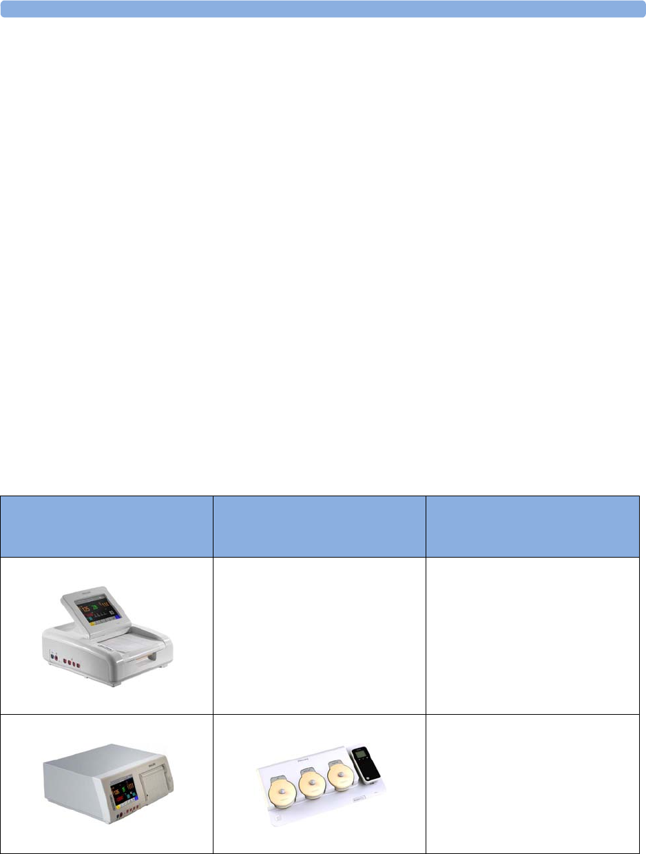
Overview of System Components
The Avalon CL system consists of the Avalon CL base station, the Avalon CL transducers, the
Avalon CL Fetal & Maternal Pod, the CL Wide Range Pod, and the IntelliVue CL Pods.
The IntelliVue CL Pods are only used for maternal measurements within the Avalon CL solution.
The following table provides an overview of all the devices.
Avalon FM20/FM30 and FM40/
FM50
Wired Transducers
Avalon CL Base Station
Avalon CL Transducers
CL Pods
FM20/FM30
M2702A and M2703A
FM40/FM50
M2704A and M2705A
Avalon CL Base Station
866074
1 Introduction
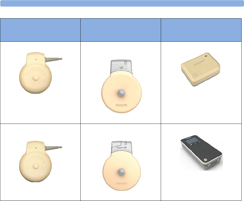
19
US transducer (wired)
M2736A
Avalon CL US Transducer
(cableless)
866076
Avalon CL Fetal & Maternal Pod
866488
Toco/ Toco MP transducer
(wired)
M2734A and M2734B
Avalon CL Toco+ MP Transducer
(cableless)
866075
Avalon CL Wide Range Pod
866487
Avalon FM20/FM30 and FM40/
FM50
Wired Transducers
Avalon CL Base Station
Avalon CL Transducers
CL Pods
1 Introduction
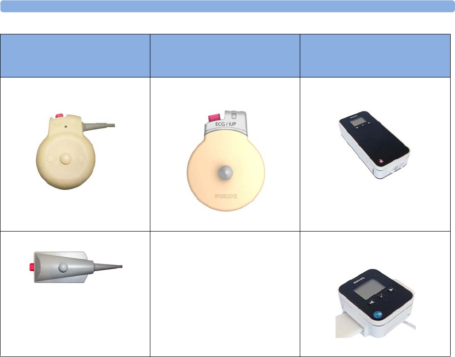
20
Toco+ transducer with ECG/IUP
capability (wired)
M2735A
Avalon CL ECG/IUP Transducer
(cableless)
866077
IntelliVue CL NBP Pod
(cableless)
865216
Patient Module for ECG/IUP
M2738A
IntelliVue CL SpO2 Pod
(cableless)
865215
Avalon FM20/FM30 and FM40/
FM50
Wired Transducers
Avalon CL Base Station
Avalon CL Transducers
CL Pods

2
21
2What's New
This section lists the most important new features and improvements to the fetal monitors and their
user interface introduced with Release L.3.
You may not have all of these features, depending on the fetal monitor configuration purchased.
What's New in Release L.3
Avalon CL Fetal & Maternal Pod
The Avalon CL Fetal & Maternal Pod is an extension of the Avalon CL solution. The Avalon
CL Fetal & Maternal Pod is used together with a single use patch with five abdominal electrodes. Prior
to use, the Avalon CL Fetal & Maternal Pod is charged and assigned at the Avalon CL base station.
The Avalon CL Fetal & Maternal Pod is used with singleton pregnancies. This solution provides
especially benefits to patients with high body mass index (BMI), although it can be used for all patients.
The Avalon CL Fetal & Maternal Pod includes the following features:
• The Avalon CL Fetal & Maternal Pod measures fetal heart rate (
aFHR
), maternal heart rate (
aHR
),
and uterine activity (
aToco
) from electrical signals.
•The
cl F&M Electrode Status
window at the monitor gives an overview of the current electrode
contact status, when the CL Fetal & Maternal Pod is placed on the electrode patch, and the patch,
and the electrodes are applied to the patient's abdominal skin. The window can be opened by
selecting the new SmartKey
cl F&M Status
, or selecting the corresponding function in the main
setup menu.
• The Avalon CL Fetal & Maternal Pod and the CL Wide Range Pod are assigned at the CL base
station in the same easy way as the IntelliVue CL Pods.
• The functions Finder LED and Call Patient work also with the Avalon CL Fetal & Maternal
Pod.
See “Avalon CL Fetal & Maternal Pod” on page 21, “CL Fetal & Maternal Electrode Patch” on
page 91, “Applying the CL Fetal & Maternal Patch and Pod” on page 100, and “CL Pod Assignment”
on page 99.

2 What's New
22
Avalon CL Wide Range Pod
The Avalon CL Wide Range Pod is an extension of the Avalon CL solution. The Avalon CL Wide
Range Pod extends the signal range of the cableless measurements. It transmits the cableless
measurement signals via the hospital WLAN/WiFi to the fetal monitors. Wearing the CL Wide Range
Pod, the patient can walk freely within the hospital's WLAN/WiFi range during monitoring. Prior to
use, the Avalon CL Wide Range Pod is charged and assigned at the Avalon CL base station.
• A new WLAN symbol is printed on the trace to indicate the use of an assigned and active Avalon
CL Wide Range Pod.
• During monitoring with an active Avalon CL Wide Range Pod, the sound from the fetal heart rate
is replaced by an artificial QRS sound (when the patient is monitored with a CL US transducer or
CL F&M Pod).
See “CL Wide Range Pod” on page 91.
Dawes/Redman
Dawes/Redman is a method of fetal monitoring trace interpretation for helping to assess fetal
well-being. The algorithm based on the Dawes/Redman criteria uses the parameters fetal heart rate,
gestational age, fetal movement, accelerations and decelerations, and long, and short term variability to
generate a report.
Not available in the USA and territories relying on FDA market clearance.
Support of XDS Remote Display
The fetal monitor software supports the IntelliVue XDS “Remote Display” functionality only in
combination with IntelliSpace Perinatal revision K or higher. From the user interface of the
IntelliSpace Perinatal system, you can access all screen-operable functions of the currently connected
fetal monitor. These functions include for example, starting and stopping physiological measurements,
changing measurement modes, changing alarm limits, and silencing alarms.
New Alarm Behavior of CL Battery Empty INOP
The CL <xxx> Battery Empty INOP issued by the CL devices and the fetal monitor has a new alarm
behavior:
• At the fetal monitor, it is issued now with a cyan INOP alarm and tone.
• At CL devices (CL transducers and CL Pods), it is issued now with a tone.
See “Patient Alarms and INOPs” on page 129.
Using CL Pods with FM20/30 #E25
The CL Pods can now also be used with a battery operated FM20 or FM30 (option #E25). The
CL Pods can be assigned and activated. The CL F&M Pod can also be charged.
See “Using Batteries” on page 110.
Entering Notes - Type a Note
In the menu
Enter Note
, it is now possible to enter a note manually, instead of selecting one of the
pre-configured notes. To enter a note, select the new menu item
Type a note
. A window with a touch
keypad opens. The typed note can be up to 30 characters long.
See “Typing Notes” on page 70.

2 What's New
23
What's New in Release J.3
Avalon CL Transducer System
The Avalon CL Transducer System provides cableless monitoring with the Avalon FM20/FM30 and
FM40/FM50 with the same functionality and performance as the wired measurement devices (e.g.
twin and triplets monitoring). The Avalon CL Transducer System has a straight-forward handling and
operating concept. The CL transducers are assigned by simply docking them at the CL base station, no
further configuration is necessary.
The Avalon CL Transducer System includes the following features:
• Cableless monitoring of twins and triplets (see “Monitoring Twin FHRs” on page 183 and
“Monitoring Triple FHRs” on page 191)
• Cableless maternal measurement Pods CL SpO2 and CL NBP (see “IntelliVue CL Pods” on
page 92)
• Maternal pulse from a CL Toco+ MP (Smart Pulse) transducer (see “Monitoring Maternal Heart /
Pulse Rate” on page 221)
• A cableless ECG/IUP transducer measuring IUP or fetal/maternal ECG (see “Monitoring
MECG Wave” on page 225 and “Monitoring FHR Using DECG” on page 199)
• Watertight cableless transducers that can be used to monitor in water (see “Underwater
Monitoring” on page 108)
• Patient call that pages an ambulating mother with an audible signal emitted by the worn CL
transducers (see “Calling Patients” on page 93)
• Out-of-range audible signal emitted by the worn CL transducers to inform an ambulating mother
that she has reached the limit of the active signal area-of-reach (see “Standard Radio Range of CL
Transducers” on page 87)
• A transducer finder LED on all CL transducers to help identify the assigned transducer (see
“Cableless Transducer LED Indication” on page 86)
Support For Use of Maternal Cableless Measurement Devices
The IntelliVue CL measurement Pods are patient-worn, battery-powered measurement devices for
SpO2 and NBP. The devices provide measurement values on the built-in display and communicate
them to the fetal monitor using the wireless short range radio (SRR) interface of the Avalon CL base
station (see “IntelliVue CL Pods” on page 92).
Maternal Temperature Measurement
To measure maternal temperature, the new optional tympanic thermometer (866149) is available for
the Avalon fetal monitors (“Monitoring Maternal Temperature” on page 249). The measurement data
is:
• documented and printed out at the local recorder, and transmitted to the obstetrical information
and surveillance system.
• displayed as a numeric on the screen.

2 What's New
24
Manually Entered Maternal Temperature Measurements
Manually measured temperatures can be entered at the fetal monitor. They are displayed as a numeric
on screen, and are printed out on the recorder trace (“Monitoring Maternal Temperature” on
page 249).
SpO2 Recordings and Transmissions
SpO2 annotation on local recorder
You can now configure the interval for printing the SpO2 numeric values on the recorder trace. With
the new configuration setting
Record on Trace
, you can set the interval to 1 or 5 minutes.
SpO2 transmission to an obstetrical information and surveillance system
You can now configure the interval for transmitting the SpO2 numeric values to an obstetrical
information and surveillance system. With the new configuration setting
Send to OB Sys
, you can set the
interval to 1 or 5 minutes.
New Design for the User Interface
The user interface for the fetal monitors has been redesigned to bring the presented information into
the foreground, letting the structural elements such as keys and frames retreat into the background.
Additionally special regard was given to making the "look and feel" similar to that of standard software
products (see “Operating and Navigating” on page 38).
New SmartKeys
•The
Start ECG
SmartKey and menu item is renamed to
Record ECG
.
• With the
Call Patient
SmartKey, you can now page patients who are ambulating wearing Avalon CL
transducers.
• With the
Tele Info
SmartKey, you can call up the
Tele Info
window on the fetal monitor display. In
the
Tele Info
window, you can control and view the status of the cableless transducers from the
connected Avalon CL base station.
• With the
Enter Temp
SmartKey, a pop-up window opens showing a numeric pad for entering
manually measured maternal temperature values.
• With the
NBP Modes
SmartKey, you can access the NBP Mode selection and setup, and can directly
start and stop a measurement.
• With the
QuickAdmit
SmartKey, you can quick admit a patient to the monitor.
All new SmartKeys are optional, and have to be configured in Configuration Mode for use (see
“SmartKeys” on page 42).
Coincidence INOP Tone
When the cross-channel verification detects that the signal of the maternal heart rate coincides with the
fetal heart rate, the
Coincidence
INOP is now issued with a tone at the fetal monitor. The
Coincidence
INOP tone has a configurable delay see “Cross-Channel Verification (CCV)” on page 159.

2 What's New
25
Increased Internal Back-up Memory
The internal back-up memory is now able to store traces and data from at least the last 3.5 hours with
the software revision J.3, and minimum 7 hours with the new mainboard hardware revision A 00.18
(see “Manually Recording Stored Data” on page 258 and “Recovering Data” on page 257).
Dual System Interface Support
If the fetal monitor is connected via a LAN connection to OB TraceVue/IntelliSpace Perinatal, the
RS232 interface can be used independently to connect e.g. an EMR system on read-only basis. The
system connected to the RS232 interface in this case cannot alter any data (such as ADT data, or the
date and time setting), or interfere with functions of the monitor, but is able to read output data. The
obstetrical information and surveillance system connected via LAN has priority.
USB Interface
An optional USB interface allows the use of bar code readers and input devices such as a keyboard, or
mouse (see “Getting to Know Your Avalon FM20/FM30”/“Bottom” on page 32 and “Getting to
Know Your Avalon FM40/FM50”/“Rear” on page 33).
Flexible Nurse Call Interface
An optional Flexible Nurse Call interface allows the connection of a nurse call device to the fetal
monitors (see “Getting to Know Your Avalon FM20/FM30”/“Bottom” on page 32 and “Getting to
Know Your Avalon FM40/FM50”/“Rear” on page 33).
DHCP Support
The DHCP support offers an alternative to BOOTP. DHCP (Dynamic Host Configuration Protocol)
enables the fetal monitors to request an IP address (internet protocol address) from the connected
network (OB TraceVue/IntelliSpace Perinatal) automatically.
Data Export Support
You can now export measurement values from the monitor to other devices via the LAN interface, or
with the optional MIB RS232 interface (see “Getting to Know Your Avalon FM20/FM30”/“Bottom”
on page 32 and “Getting to Know Your Avalon FM40/FM50”/“Rear” on page 33).
NBP Configurable Measurement Sequence
Up to four measurement cycles can be set up which will run consecutively. For each cycle, you can set
the number of measurements and the interval between them. By setting the last cycle to run
continuously, you can have regular measurements continue after the sequence has run (see “Enabling
Sequence Mode and Setting Up the Sequence” on page 240.
Alarms Enhancements
In addition to the standard cyan INOPs, some INOPs can now be configured as red or yellow INOPs
to provide a severity indication (
ECG Leads Off
,
Cuff Overpress
,
Cuff NotDeflated
,
Battery Empty
,
No
Pulse
) (see “Alarms” on page 117).

2 What's New
26
Alarm Reminder
In Configuration Mode, you can set now an
Alarm Reminder
. The
Alarm Reminder
emits an audible
reminder of alarm conditions that remain active after the alarm is acknowledged. This reminder may
take the form of a repetition of the alarm tone for a limited time, or an unlimited repetition of the
alarm tone (this is the same as a new alarm). The interval between silencing the alarm and sounding the
reminder tone can be set to one, two, or three minutes (see “Alarm Reminder” on page 122).
Auto Free
In Configuration Mode, you can now set an
Auto Free
setting which discharges a patient automatically
when the fetal monitor has been powered off, or is in standby mode for a set time. Only the
demographic patient data is deleted, the trace data is not affected.
3
27
3Basic Operation
This chapter gives you an overview of the monitor and its functions. It tells you how to perform tasks
that are common to all measurements (such as entering data, switching on a measurement, changing
some monitor settings, and setting up the recorder). The alarms section gives an overview of alarms.
The remaining sections tell you how to perform individual measurements, and how to care for and
maintain the equipment.

3 Basic Operation
28
Supported Measurements
Different measurements for the same physiological parameter may have a different appearance on the
trace, due to: variability (HR), averaging, delay, amplitude, or artifacts. Before interpreting the trace,
regard the fetal monitor setup and transducers used.
The following Fetal measurements are supported:
The following Maternal measurements are supported:
Measurements FM20 FM30 FM40 FM50
Fetal Heart Rate (FHR) via
US (including Twins)
Standard Standard Standard Standard
Triple FHR via US Optional Optional Optional Optional
dFHR via Direct ECG
(DECG)
- Standard - Standard
aFHR via CL F&M Pod Optional Optional Optional Optional
Toco Standard Standard Standard Standard
aToco via CL F&M Pod Optional Optional Optional Optional
Intrauterine Pressure (IUP) - Standard - Standard
Measurements FM20 FM30 FM40 FM50
Maternal Heart Rate (MHR)
via Maternal ECG Electrodes
Standard Standard Standard Standard
Maternal ECG (MECG wave) - Standard - Standard
aHR via CL F&M Pod Optional Optional Optional Optional
Maternal Pulse from Toco Standard Standard Standard Standard
Noninvasive Blood Pressure
with Pulse Rate
Optional Optional Optional Optional
Pulse Oximetry (Maternal
SpO2) with Pulse Rate
Optional Optional Optional Optional
Maternal Temperature Optional Optional Optional Optional
3 Basic Operation
29
Avalon FM20 and FM30
This section outlines the capabilities of your monitor.
Avalon FM20
The Avalon FM20 fetal/maternal monitor provides a solution for external fetal monitoring
applications, and optional noninvasive maternal vital signs.
You can monitor fetal heart rates (FHRs) externally using ultrasound, uterine activity and maternal
pulse using an external Toco transducer, and the maternal heart rate (MHR) with maternal ECG
electrodes, and optionally, noninvasive blood pressure and maternal oxygen saturation (SpO2).
Measurements are displayed on a 6.5 inch color display as numerics. The display is a touchscreen, and
you operate the monitor using this touchscreen interface. The integrated recorder documents fetal and
maternal measurements as well as the user-defined annotations.
You can connect the monitor to an OB TraceVue/IntelliSpace Perinatal system via the RS232
connection, or over a LAN connection (with OB TraceVue Revision E.00.00 and later, or IntelliSpace
Perinatal Revision H.0 and later).
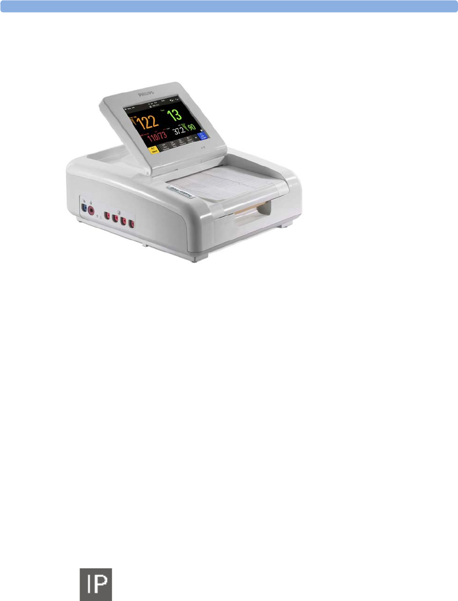
Avalon FM30
The Avalon FM30 fetal/maternal monitor offers a solution for both external and internal fetal
monitoring applications, and optional noninvasive maternal vital signs.
The Avalon FM30 shares all the features and capabilities of the Avalon FM20. In addition, you can
monitor one FHR internally with a direct fetal electrocardiogram (DECG), uterine activity internally
using an intrauterine pressure (IUP) catheter together with a Toco+ transducer or patient module.
The Avalon FM30 carries the IP label, indicating that it is capable of intrapartum monitoring.
3 Basic Operation
30
FM20/30 with
Battery
Option #E25
Only
The battery option for the FM20/30 provides support for the in-transport monitoring of all
measurements when disconnected from a power supply. Existing data storage is automatically
uploaded to OB TraceVue or IntelliSpace Perinatal after reconnecting it to the system. Trace printing
during transport is also possible.
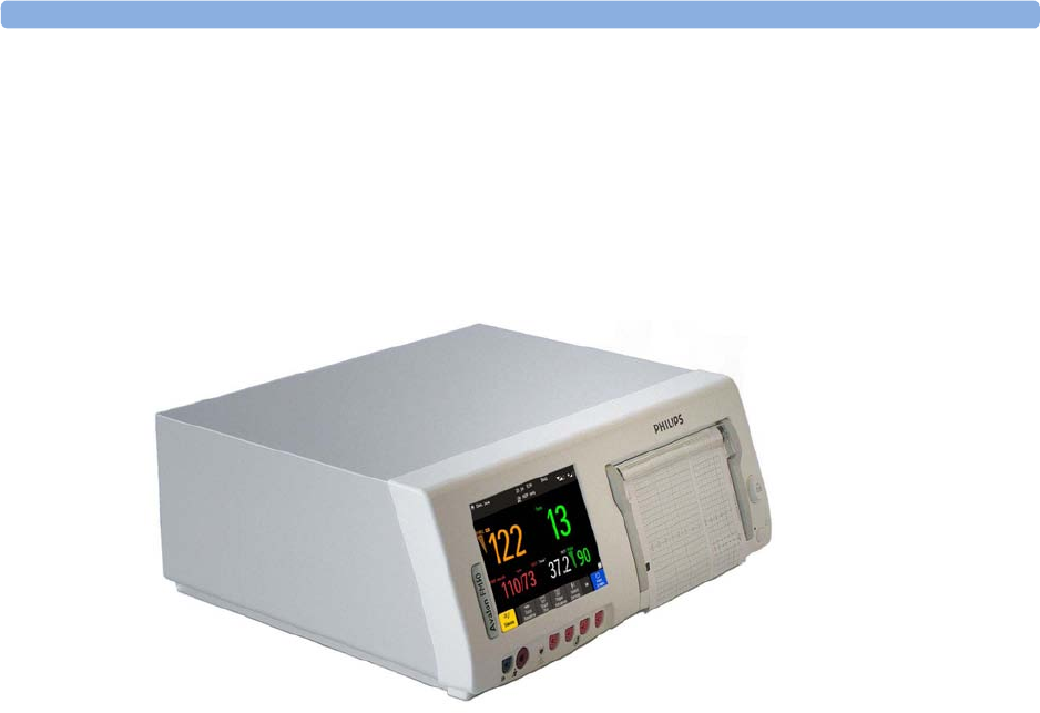
Avalon FM40 and FM50
This section outlines the capabilities of your monitor.
Avalon FM40
The Avalon FM40 fetal/maternal monitor provides a solution for external fetal monitoring
applications, and noninvasive maternal vital signs.
You can monitor fetal heart rates (FHRs) externally using ultrasound, uterine activity using an external
Toco transducer, and the maternal heart rate (MHR) via maternal ECG electrodes, and noninvasive
blood pressure and maternal oxygen saturation (SpO2).
Measurements are displayed on a 6.5 inch color display as numerics. The display is a touchscreen, and
you operate the monitor using this touchscreen interface. The integrated recorder documents fetal and
maternal measurements as well as the user-defined annotations.
You can connect the monitor to an OB TraceVue/IntelliSpace Perinatal system with the RS232
connection, or over a LAN connection (with OB TraceVue Revision E.00.00 and later, or IntelliSpace
Perinatal Revision H.0 and later).
3 Basic Operation
31
Avalon FM50
The Avalon FM50 fetal/maternal monitor offers a solution for both external and internal fetal
monitoring applications, and noninvasive maternal vital signs.
The Avalon FM50 shares all the features and capabilities of the Avalon FM40. In addition, you can
monitor one FHR internally with a direct fetal electrocardiogram (DECG), and uterine activity
internally using an intrauterine pressure (IUP) catheter together with a Toco+ transducer or patient
module.
The Avalon FM50 carries the IP label, indicating that it is capable of intrapartum monitoring.
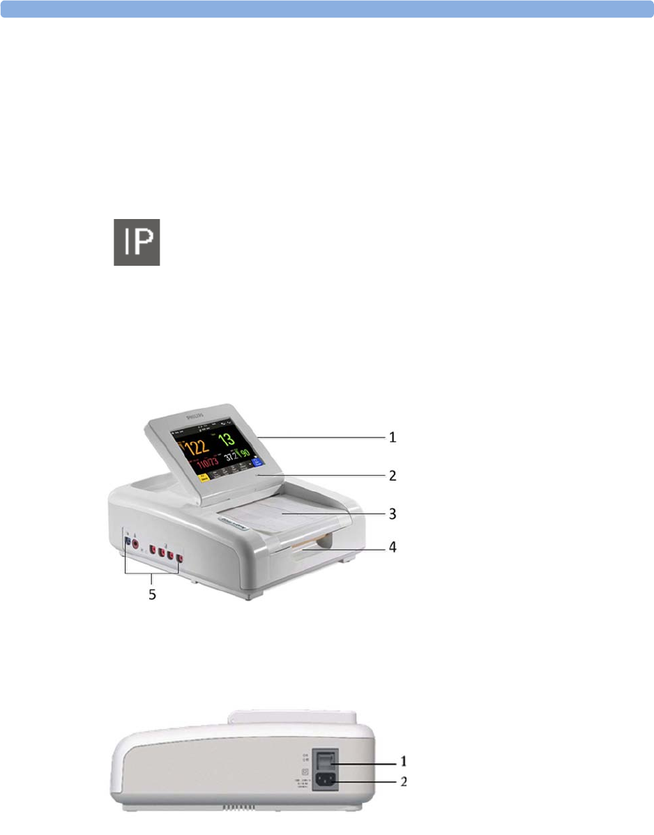
Getting to Know Your Avalon FM20/FM30
Overview
Right Side
1Touchscreen display (tilt and fold)
2Power LED
3Paper drawer
4Paper drawer release
5Connectors
1On/Off switch
2Power connector
3 Basic Operation
32
with Battery
Option
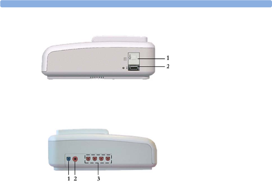
Left Side
Each of the fetal sensor sockets accepts any fetal transducer, one Avalon CL or one Avalon CTS
Cableless Fetal Transducer System base station, or an event marker.
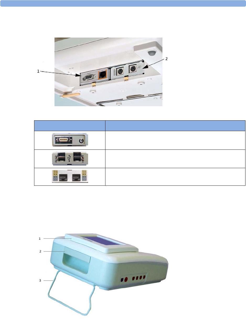
Bottom
There are five optional interfaces available for the Avalon FM20/30 monitor:
• LAN/RS232 system interface
• Dual PS/2 interface
• Dual MIB/RS232 interface
• Flexible Nurse Call interface
• USB ports interface
1On/Standby button with power LED
2MSL connector for external power
supply
1SpO2 socket (optional)
2Noninvasive Blood Pressure
socket (optional)
3Fetal sensor sockets
3 Basic Operation
33
You can use two of the five optional interfaces at the same time.
Rear
1LAN/RS232 system
interface
2Dual PS/2 system
interface
Optional Interfaces Description
Flexible nurse call interface card
Quad. USB ports
Dual MIB/RS232
1Display release
2Carrying handle
3Built-in stand
3 Basic Operation
34
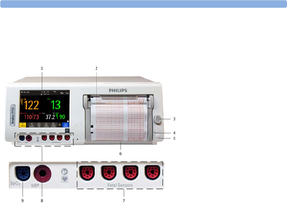
Getting to Know Your Avalon FM40/FM50
Front
Connect any fetal sensor or patient module at the fetal sensor sockets, including an Avalon CL or an
Avalon CTS via interface cable (with red connector).
1Touchscreen color display
2Transparent paper guide with tear-off
edge
3Paper eject button
4Power LED
5On/Standby button
6Recorder paper table
7Fetal sensor sockets
8Noninvasive blood pressure socket
(optional)
9SpO2 socket (optional)
3 Basic Operation
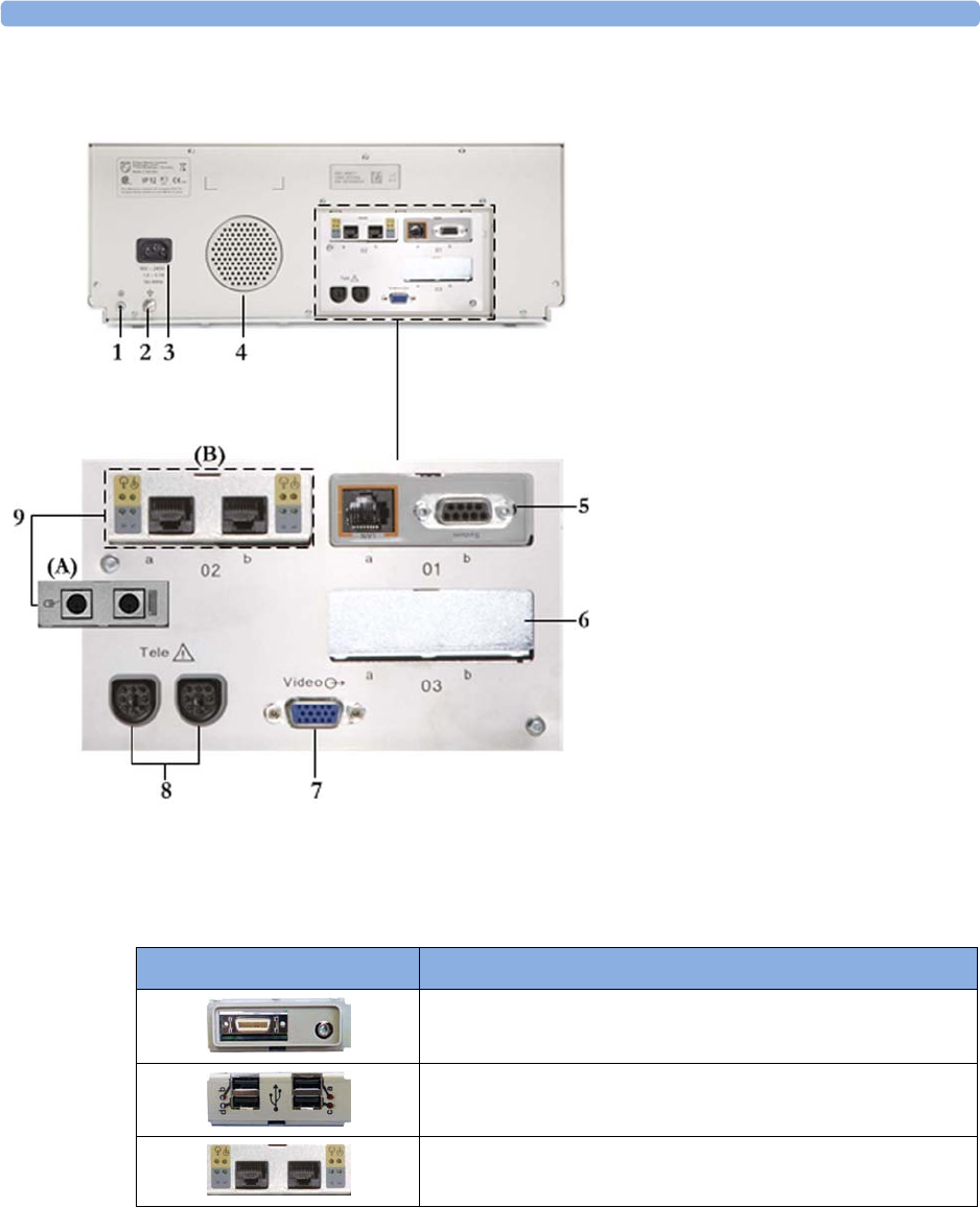
35
Rear
Two Avalon CL base stations, or one Avalon CTS can be also connected to the Telemetry interface
sockets using the interface cable (with black connector).
Additional Optional Interfaces
1Reserved for future use: protective
earth intended for use in system
installations
2Equipotential grounding point
3Power cord connector
4Loudspeaker
5Slot 01 for optional LAN/RS232
system interface (for connection to an
obstetrical information and
surveillance system)
6Slot 03 reserved for future use
7Video output (VGA)
8Telemetry interface
9Slot 02 for optional interfaces: Either
dual PS/2 system interface (A) for
mouse and keyboard connection) Or
MIB interface (B) for external
touchscreen connection, or the
optional interfaces for the flexible
nurse call or USB ports
Optional Interfaces Description
Flexible nurse call interface card
Quad. USB ports
Dual MIB/RS232 interface
3 Basic Operation
36
Connecting the Monitor to AC Mains
WARNING
• Always use the supplied power cord with the earthed mains plug to connect to an earthed AC
mains socket. Never adapt the mains plug from the fetal monitor to fit an unearthed AC mains
socket.
• Check that the line frequency is correctly configured in the
Global Settings
menu.
•FM20/FM30 only: The protective earth conductor is required for EMC purposes. It has no
protective function against electric shock. Double and/or reinforced insulation protects this
device against electric shock.
• Do not use AC mains extension cords or multiple portable socket-outlets.
Always ensure that the monitor is positioned so that the AC mains plug is easily accessible, to allow
disconnection of the monitor from the AC mains.
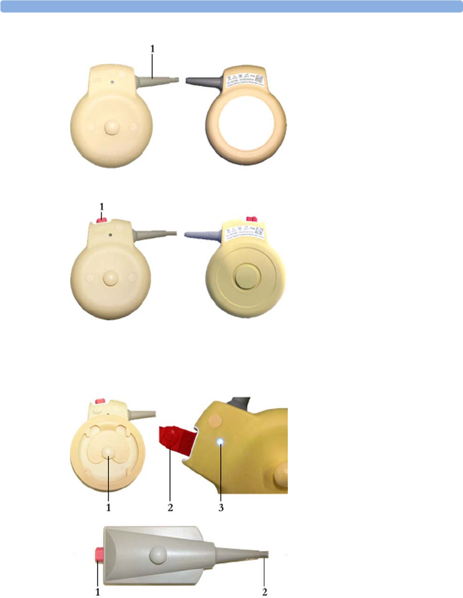
Wired Transducers
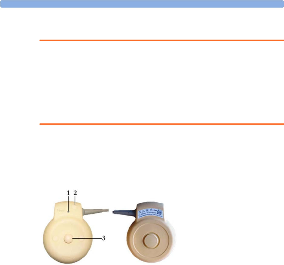
Toco (M2734A) and Toco MP Transducer (M2734B)
1Transducer finder LED - lights up
on the transducer supporting to
identify the measurement source
2"MP" for M2734B "Toco MP"
transducers (additionally capable
of providing the maternal pulse
measurement)
3Belt button
3 Basic Operation
37
Ultrasound Transducer (M2736A)
1Cable - connects to any of the
four fetal sensor sockets on the
monitor
The M2736AA US transducer is
identical to the M2736A US
transducer, including all specifications
Toco+ Transducer with ECG/IUP capability
(M2735A)
1Connector - for connecting
ECG/IUP adapter cables
(M2735A Toco+ transducer only)
1Butterfly belt clip (shown fitted;
for use with belts without button
holes)
2Close-up of MECG adapter cable
connected to Toco+ transducer
3Close-up of active finder LED
Patient Module for ECG/IUP (M2738A)
1Connector - for connecting ECG/
IUP adapter cables (same as for
Toco+ transducer)
2Cable - connects to any of the four
fetal sensor sockets on the monitor
3 Basic Operation
38
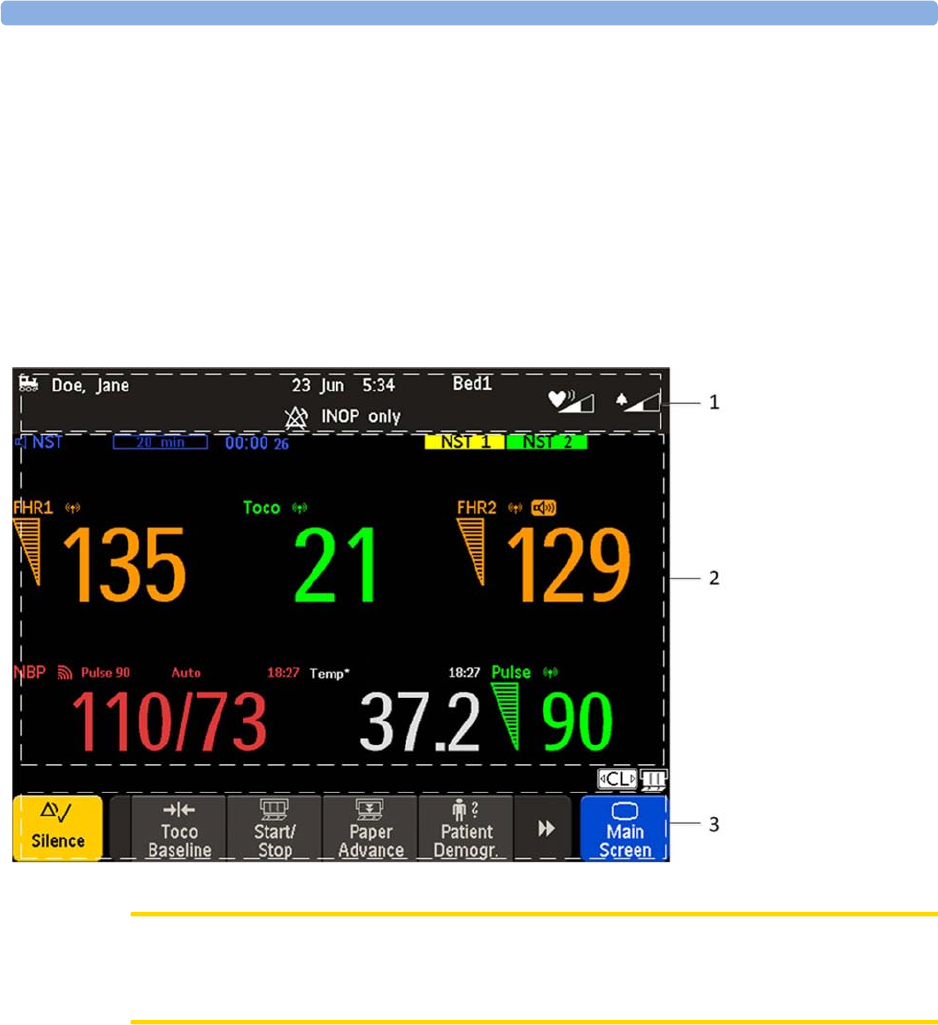
Operating and Navigating
Your monitor has a touchscreen. Everything you need to operate the monitor, except the on and off
switch, is contained on its screen. Most screen elements are interactive. Screen elements include
measurement numerics, screen keys, information fields, status indicators, alarms fields, and menus.
Operator Position
The typical operator's position is in front of the monitor.
FM40/50 If an optional external touch display is connected to the monitor, you can operate the monitor using
the external touch display.
CAUTION
The screen contains sensitive personal data. For information how to protect personal information, see
“Protecting Personal Information” on page 17.
1Monitor
information line
2Measurement area
3Key area
3 Basic Operation
39
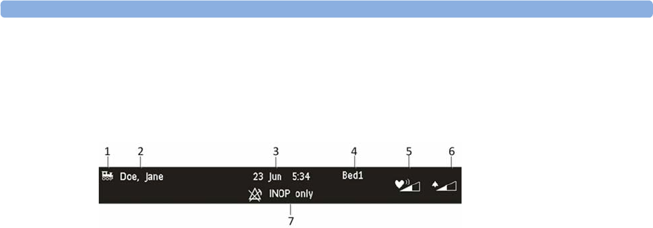
Screen Elements
Monitor Information Line
1LAN connection status indicator only. RS232 system connection is not indicated. The
locomotive icon indicates if the fetal monitor is connected to OB TraceVue/IntelliSpace
Perinatal, via a LAN cable or not.
2Patient identification
3Date and time
4Bed label (when connected to a Philips OB TraceVue/IntelliSpace Perinatal system)
5Fetal heart sound volume adjust/indicator
6Alarm volume adjust/indicator
7INOP and alarm status area - shows active alarm messages
3 Basic Operation
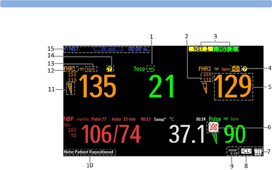
40
Measurement Area
1Antenna symbol (indicates a cableless measurement from a connected Avalon CL or Avalon CTS
system)
2Configurable alarm limits
3NST test
4Audio source symbol
5Measurement numeric
6Alarms off symbol
7Fetal trace recorder - status indicator
8Avalon CL or Avalon CTS system - status indicator
9Battery status indicator
10 Status line - shows status and prompt messages
11 Signal quality indicator: good, acceptable, poor
12 Fetal heart rate measurement label
13 Measurement unit (configurable)
14 Coincidence symbol (see “Cross-Channel Verification (CCV)” on page 159)
15 NST timer, if configured (default is Off)
3 Basic Operation
41
Screen Details
Key Area
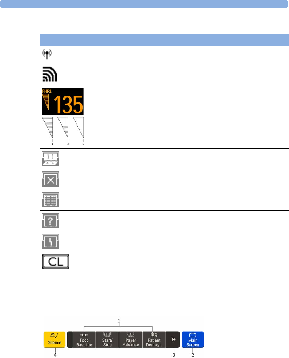
Icon Description
The antenna symbol indicates a cableless measurement
(Avalon CL or Avalon CTS).
Indicates a short range radio measurement (CL Pods).
Signal quality indicator:
1Good
2Acceptable
3Poor
Fetal trace recorder - status indicator
Fetal recorder is on
Fetal recorder is off (when
Paper Save Mode
is off)
Fetal recorder is off (when
Paper Save Mode
is on)
There is a user-solvable recorder error (paper out, paper jam,
wrong paper scale set)
Fetal recorder is defective: call service
When an Avalon CL or Avalon CTS system is connected to the
monitor, a
CL
symbol is shown. It changes with the states of the
connected cableless device see “Cableless Status Indication” on
page 95.
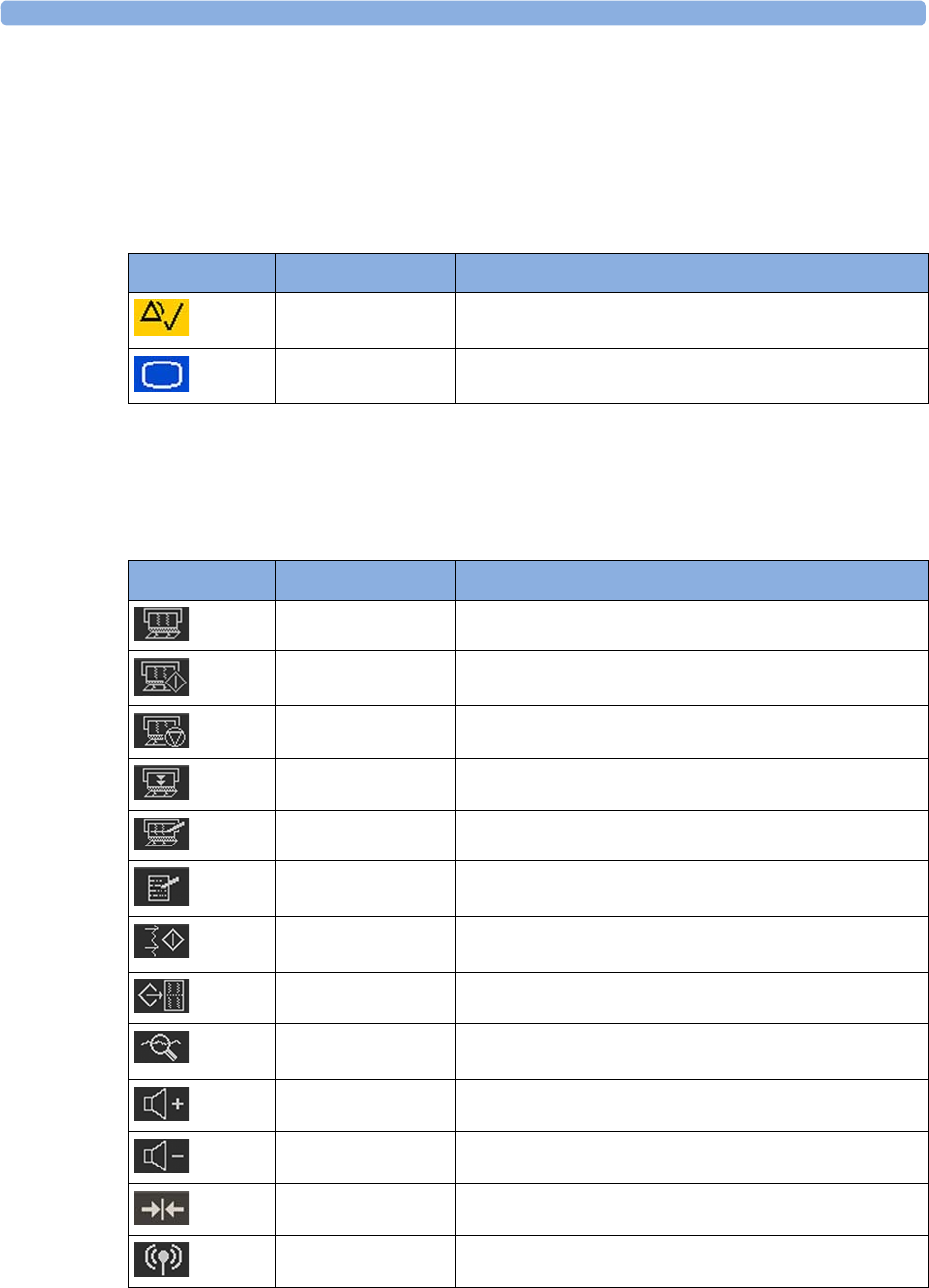
1SmartKeys - these can vary according to your monitor's configuration
2
Main Screen
- closes all open menus and windows and returns to main screen
3Scroll to display more SmartKeys
4
Silence
- acknowledges all active alarms by switching off audible alarm indicators
3 Basic Operation
42
Keys
The monitor has three different types of keys.
Permanent Keys
A permanent key is a graphical key that remains permanently on the screen, giving you fast access to
functions.
SmartKeys
SmartKeys are configurable graphical keys, located at the bottom of the main screen. They give you
fast access to functions. The selection of SmartKeys available on your monitor depends on your
monitor configuration, and on the options purchased.
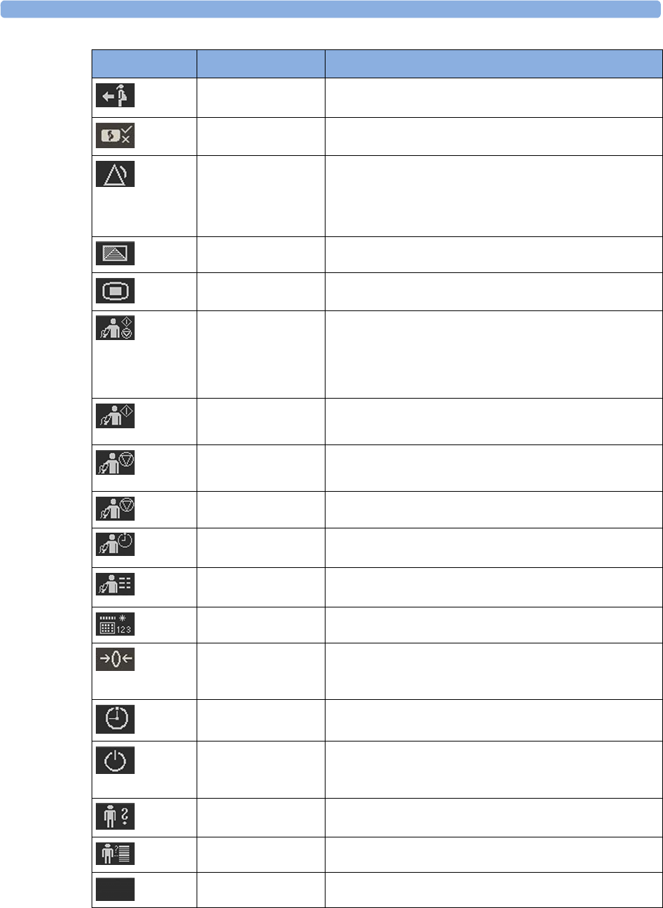
Key Name Function
Silence
Acknowledges all active alarms by switching off audible
alarm indicators.
Main Screen
Closes all open menus and windows and returns to the
main screen.
SmartKey Name Function
FRStart/Stop
Turns the trace recorder on or off
Start Rec
Turns the trace recorder on
Stop Rec
Turns the trace recorder off
Paper Advance
Advances the paper automatically to the next fold
Set Marker
Marks an event
Enter Notes
Enters notes
Record ECG
Starts printing the MECG, DECG, or both waves, when
both are available
Stored Rec
Prints trace data from the monitor's memory
NST Report
Initiates an NST trace interpretation and obtains a Non-
stress test (NST) report
Sound Vol. Up
Increases the fetal heart rate volume
Sound Vol. Down
Decreases the fetal heart rate volume
Toco/IUP Bsl
Resets Toco baseline
Tele Info
Calls up the
Tele Info
window
3 Basic Operation
43
Call Patient
Pages the patient. Only enabled if at least one
CL transducer is currently active
cl F&M Status
Calls up the
cl F&M Electrode Status
window
Pause Alarms
Pauses alarm indicators. Pause duration depends on
monitor configuration. If the pause duration is infinite, this
key is labeled
Alarms Off
Select again to immediately re-enable alarm indicators
Defaults
Loads User Default
Main Setup
Enters main setup menu
Strt/Stp NBP
Starts/stops manual noninvasive blood pressure
measurement
Starts auto series
Stops current automatic measurement within series
Start NBP
Starts manual noninvasive blood pressure measurement
Starts auto series
Stop NBP
Stops manual noninvasive blood pressure measurement
Stops current automatic measurement within series
Stop All NBP
Stops all noninvasive blood pressure measurements
Repeat NBP
Sets the time interval between two noninvasive blood
pressure measurements
NBP Modes
Access NBP mode selection and setup, with direct start/
stop function
Enter Temp
Allows the manual input of the patient's temperature
Zero IUP
Resets the display and trace to 0. If you do not zero the IUP
measurement properly, the pressure trace may exceed the
paper scaling.
Timer
Enters NST timer window
Standby
Switches to standby screen, suspends monitoring. All
numerics and waves disappear from the display. All settings
and patient data information are retained
Patient Demogr.
Enters the patient identification menu to admit/discharge
QuickAdmit
Quick admits the patient for monitoring
Blank Key
Blank key, can be used as divider between a group of keys
SmartKey Name Function

3 Basic Operation
44
Pop-Up Keys
Pop-up keys are context-sensitive graphical keys that appear automatically on the monitor screen when
required. For example, the
Confirm
pop-up key appears when you need to confirm a change.
Using the Touchscreen
Select screen elements by pressing them directly on the monitor's screen.
Disabling Touchscreen Operation
1To temporarily disable the touchscreen operation of the monitor, press and hold the
Main Screen
permanent key for about three seconds. A red padlock will blink on the
Main Screen
permanent
key.
2Press and hold the
Main Screen
permanent key again for about three seconds to re-enable the
touchscreen operation.
Operating Modes
When you switch on the monitor, it starts up in Monitoring Mode. To change to a different mode:
1Select the
Main Setup
menu.
2Select
Operating Modes
and select a mode.
Your monitor has four operating modes. Some are passcode protected.
Mode Description Password
Protected
Monitoring Mode The Monitoring Mode is the normal operating mode to
monitor patients. You can change elements such as alarm
limits. When you discharge the patient, these elements
return to their default values.
You cannot select or change grayed out items. These items
are for your information only. To change these items,
switch to the Configuration Mode.
no
Demo Mode The Demo Mode is used for demonstration and training
purposes. Do not change into Demo Mode during
monitoring. When transducers are connected to the
monitor and the recorder is on, a demo trace is recorded.
But the demo trace is not transmitted when the fetal
monitor is connected via RS232 to an information and
surveillance system such as OB TraceVue/IntelliSpace
Perinatal.
yes

3 Basic Operation
45
A field displayed at the fetal monitor screen indicates if the monitor is in Demonstration Mode,
Configuration Mode, or Service Mode. To change to a different mode, select this field.
Automatic Screen Layouts
Your monitor's preconfigured screen layouts define how measurement information is arranged on the
screen. The monitor automatically applies the correct screen layout for the measurements you are
monitoring. No user action is required.
Connecting or disconnecting transducers, or activating or deactivating a cableless measurement, results
in an automatic adjustment of the screen layout. When a measurement is off, its numerics are removed
from the monitor's screen. The monitor stops acquiring data and generating alarms for this
measurement. If you disconnect a transducer while it is performing a measurement, the monitor issues
a disconnect INOP (and in the case of SpO2, replaces the measurement numeric with a question
mark).
Settings
This section describes the various settings available on the monitor.
Active Settings
What the monitor displays, and the way it operates, is controlled by its settings. They determine sound
volume settings, recorder settings, high and low alarm limits and so forth.
The "active settings" are the current settings the monitor uses, including any adjustments made by the
last user. Active settings are not permanent, but are retained after a loss of mains power.
There are also two preconfigured default settings:
•User Default
• Factory Default
Configuration Mode The Configuration Mode is for personnel trained in
configuration tasks. You can change and store the default
values and patient profiles permanently in the
Configuration Mode. These tasks are described in the
Configuration Guide. During installation, the fetal
monitor is configured for use in your environment. This
configuration defines the default settings you work with
when you switch on the fetal monitor.
yes
Service Mode The Service Mode is for trained and authorized service
personnel only.
yes
Mode Description Password
Protected

3 Basic Operation
46
User Default
The
User Defaults
are a complete configuration stored in the monitor's long-term memory. You can
store the active settings, modified to your preference, in the
User Defaults
(in Configuration Mode).
In Monitoring Mode, you can load the
User Defaults
settings to return to your preferred settings:
1Select the
Defaults
SmartKey.
2Select
Confirm
in the dialog box to load the
User Defaults
.
Factory Default
The
Factory Defaults
is a complete configuration predefined at the factory. You cannot modify it. In
Configuration Mode, you can load the
Factory Defaults
as the active settings.
CAUTION
This resets all settings to factory defined values, but be aware that some values will differ from those
with which the fetal monitor was originally shipped from the factory (recorder speed and paper scale
type will need to be corrected, for instance). After loading the
Factory Defaults
, check the settings, and
if necessary, change them to the settings you normally use.
You can use the
Factory Defaults
as the basis for producing your
User Defaults
. See the Configuration
Guide for details.
Global Settings
General monitor configuration settings are stored in the
Global Settings
. These include settings for line
frequency, QRS type, and whether the monitor is automatically reset to the
User Defaults
after a power
interruption of more than one minute. You can change the
Global Settings
in Configuration Mode.
Changing Measurement Settings
Each measurement has a setup menu in which you can adjust all of its settings. You can enter a setup
menu:
1with the measurement numeric - select the measurement numeric on the screen to enter its setup
menu. For example, to enter the
Setup FHR1
menu, select the
FHR1
(fetal heart rate 1) numeric.
2with the
Main Setup
SmartKey - if you want to set up a measurement when the measurement is
switched off, use the
Main Setup
SmartKey and select
Measurements
. Then select the measurement
name from the pop-up list. With this SmartKey you can access any setup menu in the monitor.
This guide always describes the entry method using the measurement's setup menu. You can use the
method you prefer.

3 Basic Operation
47
Changing Monitor Settings
To change monitor settings such as brightness, or touch tone volume:
1Enter the
Main Setup
menu.
2Select the setting you want to change, or select
User Interface
to enter a sub menu where you can
change user interface settings.
Adjusting the Screen Brightness
1Enter the
Main Setup
menu.
2Select
User Interface
.
3Select
Brightness
.
4Select the appropriate setting for the screen brightness. 10 is the brightest, 1 is the least bright.
Optimum
is suitable for most situations.
Adjusting Audio Volume
Here you can adjust the audio volume for
Alarm Volume
,
QRS Volume
, and
Timer Volume
. To adjust an
audio volume:
1Enter the
Main Setup
menu.
2Select
User Interface
.
3Select
Audio Volumes
, then select one of the volume types, and select an audio level. 10 is the
loudest and 1 is the quietest. Selecting zero switches the volume off.
Setting the Date and Time
The current date and time is displayed in its own element in the information line of the monitor screen.
1Select the date and time screen element from the monitor's information line to enter the
Date,
Time
menu.
2Select, in turn, the
Year
,
Month
,
Day
,
Hour
(in 24 hour format), and
Minute
, as necessary
.
3Select
Store Date, Time
to change the date and time.
WARNING
Do not change the date and time setting, if the fetal monitor is connected to a Philips OB TraceVue/
IntelliSpace Perinatal system. The monitor uses the OB TraceVue/IntelliSpace Perinatal system date
and time, including daylight saving time changes. As long as the fetal monitor is connected to the OB
TraceVue/IntelliSpace Perinatal system via the LAN-setup (locomotive symbol displayed on the
monitor's screen), the option to change the date and time settings at the fetal monitor are disabled, this
is not valid for RS232 connections, or the connection to other systems.

3 Basic Operation
48
When disconnected from AC power, the monitor retains the date and time setting for at least two
months. If the monitor is off longer than two months, and the operating system detects that the date
and time settings are invalid, the monitor initiates a "cold" start and sets the date to 1 Jan 1997 and the
time to 00:00.
Checking Your Monitor Revision
1Select
Main Setup
,
Revisions
to open the
Monitor Revision
menu.
2From the
Monitor Revision
menu, select the monitor component for which you need revision
information.
Preparing to Monitor
Confirm fetal life before you begin fetal monitoring. Familiarize yourself with the basic operation
principles before you start to monitor.
CAUTION
Check the fetal monitors housing for damage before you start to monitor as part of your safety
precautions.
After you switch on the monitor:
1Check that you have the correct patient cables and transducers plugged in for the measurement
you want to monitor.
2If you use an Avalon CL or Avalon CTS system, check if the cableless transducers are ready and
charged (apparent by either a lit up green or yellow LED indicator).
3Admit your patient to the monitor (see “Admitting a Patient” on page 147).
4Check that the alarm limits, alarm and fetal heart rate volumes, patient category, and so forth, are
appropriate for your patient. Change the settings if necessary.
5Refer to the appropriate measurement section for details of how to perform the measurements
you require.
6Start recording.
There is no special emergency access for the Avalon Fetal monitors. For all clinical use cases according
the Intended Use, the monitors are taken into operation by connecting them to AC mains and by
switching them on.
Switching On: FM20/FM30
1Connect the monitor to AC mains and switch the monitor on.
– The green power-on LED lights up.
– The monitor performs a self-test as it starts up.
Selftest: OK
, the serial number, and revisions
for the software and firmware are printed on the fetal trace paper (if recorder
Auto Start
is
configured to
On
).
– The monitor display comes on.
– There is a start-up tone from the loudspeaker.
Battery
Option • If this option has been chosen, the green power-on LED on both the external power supply and
the battery LED indicator will light up.
3 Basic Operation
49
Switching On: FM40/FM50
1Connect the monitor to AC mains.
– The green LED lights up.
2Press the On/Standby switch.
– The monitor performs a self-test as it starts up.
Selftest: OK
, the serial number, and revisions
for the software and firmware are printed on the fetal trace paper (if recorder
Auto Start
is
configured to
On
).
– The monitor display comes on.
– There is a start-up tone from the loudspeaker.
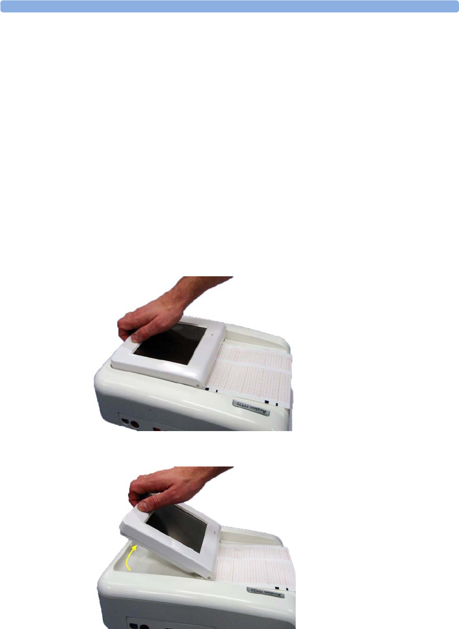
Adjusting the Display Angle (FM20/FM30)
You can tilt the display on the FM20 and FM30 to one of five different positions, or you can fold it
completely down. The tilt/fold mechanism works on a one-way ratchet system. You hear a click as
each of the five positions is reached. The screen can be folded back down only after tilting the display
forwards as far as it will go.
To tilt the display from the folded position:
1Unlock the display by releasing the catch.
2Lift the display forward. You will hear a click as the first position engages. If you want to tilt the
display further, lift the display further forward until you reach the desired angle.
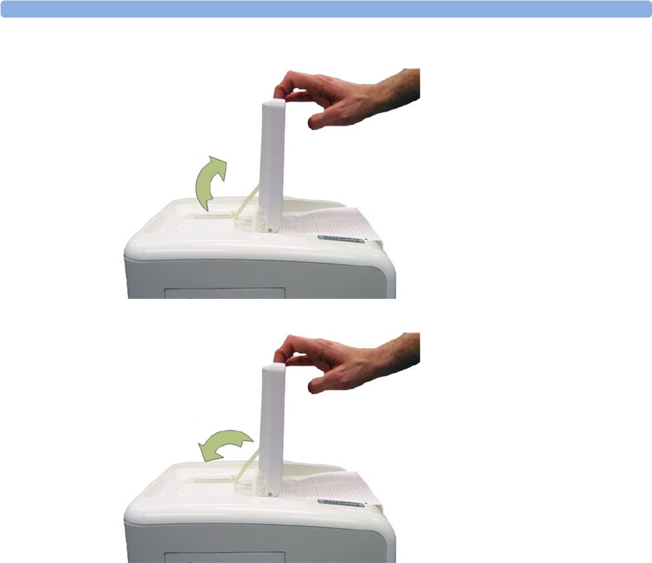
3 Basic Operation
50
3To fold the display, pull the display forwards as far as it will go.
4Then push the display all the way back until it clicks shut.
If your monitor is wall-mounted, the display should be folded flat.
Fastening Belts and Transducers
You can use more than one belt if, for example, you are monitoring uterine activity and FHR
simultaneously. There are two basic ways to fasten belts and transducers:
• Belts with button fixings.
• Velcro belts together with the butterfly belt clip.
What You Need
• Ultrasound transducer
• Toco MP or CL Toco+ MP transducer
• Ultrasound gel
• Transducer belt (and optional butterfly belt clip, if applicable)

3 Basic Operation
51
Using Belts with Button Fixings
1Place the transducer belt across the bed, so that the fixing button will face away from the mother
when it is fastened.
2Lie the patient on the bed and arrange the belt around her until it is tight but still comfortable.
3Fasten the belt by pushing the fixing button through the overlapping section of the belt. Ensure
that the fixing button and the loose ends of the belt are at the patient's side.
4When you have positioned a transducer satisfactorily, you can attach it to the belt by pushing the
belt button on the transducer through one of the holes in the belt.
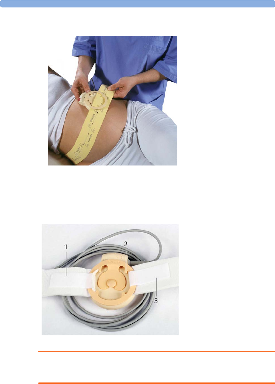
3 Basic Operation
52
5Alternatively, attach the butterfly belt clip to the transducer belt button and use this to attach the
transducer to the belt. The clip allows you to slide the transducer for easy repositioning.
Using Belt with Velcro Fixings
Insert one end of the belt between the belt guides on one side of the butterfly belt clip, and secure with
the velcro fixing. Insert the other end of the belt between the belt guides on the other side of the
butterfly belt clip, adjust for the correct tension, then secure with the velcro fixing.
WARNING
When connecting devices for acquiring measurements, always position cables and NBP tubing
carefully to avoid entanglement or potential strangulation.
1Velcro fixing
2Belt guides
3Velcro fixing
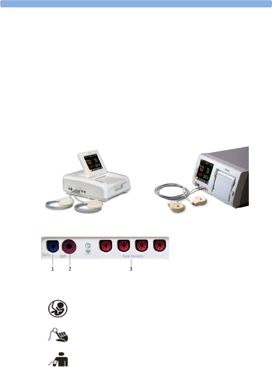
3 Basic Operation
53
Repositioning Transducers
A patient possibly wears transducers for long periods without interruption. In rare cases, skin
irritations may occur if a transducer is attached to one location for a longer period. To ensure there are
no adverse effects on the patient's skin, inspect the transducer application site at least every three
hours. If the skin quality changes, move the transducer to another site.
The ultrasound transducer is often repositioned to follow the fetal heart as part of the normal
monitoring process, but this is not so for the Toco transducer. Therefore, remember to check its
application site (between contractions) at least every three hours.
To reduce the risk of skin irritations, do not allow a cleaning or disinfecting agent to remain on the
transducer. Follow all instructions that accompany the specific cleaning and disinfecting agents you are
using. Remove agent residues with a cloth dampened in water before applying a transducer to a patient.
See “Care and Cleaning” on page 261 for further information, and a list of approved agents.
Connecting a Transducer to the Monitor
1SpO2 socket
2Noninvasive blood pressure socket
3Fetal sensor sockets
You can plug a fetal transducer, an ECG/IUP patient module, an Avalon CL or
Avalon CTS Cableless Fetal Transducer System interface cable (red connector), or
an external event marker into any of the four fetal sensor sockets marked by the
fetal symbol, or "Fetal Sensors" (depending on geography).
For measuring maternal SpO2, connect the sensor to the socket marked with the
SpO2 symbol or "SpO2" (depending on geography).
For maternal noninvasive blood pressure, connect the cuff to the socket marked
with the NBP symbol or "NBP" (depending on geography).
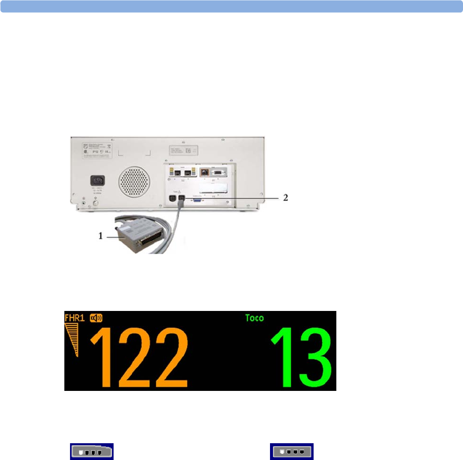
3 Basic Operation
54
For the FM20 and FM30, you can connect an Avalon CL or Avalon CTS Cableless Fetal Transducer
system interface cable (red connector) to one of the fetal sensor sockets at the left side of the monitor.
For the FM40 and FM50, you can connect an Avalon CL or Avalon CTS Cableless Fetal Transducer
System interface cable (black connector) to one of the two dedicated black sockets marked "Tele" at
the rear of the monitor, as an alternative to using one of the fetal sensor sockets (red connector) at the
front.
What You See on the Monitor
When you connect a transducer or sensor, the measurement numeric appears on the screen.
Fetal heart rate measurements are labeled in the order in which you plug in the transducers for those
measurements. It does not matter which fetal sensor socket you use, as the monitor allocates a channel
automatically. For instance, when monitoring triplets, the first transducer you connect is automatically
allocated a channel, and the measurement is labeled
FHR1
, the second
FHR2
, and the third
FHR3
. See
also chapters “Monitoring Twin FHRs” on page 183 and “Monitoring Triple FHRs” on page 191.
When you touch a measurement numeric on the screen, the setup menu for that measurement opens.
The fetal sensor socket to which the transducer for this measurement is connected is identified by the
transducer position indicator in the setup menu header.
1Interface cable to Avalon CL and
Avalon CTS Cableless Fetal
Transducer System.
2Connect the black connector to one
of the two black sockets (marked
"Tele") on the rear of the monitor.
FM20/FM30 FM40/FM50
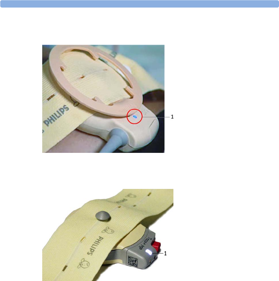
3 Basic Operation
55
The blue finder LED on a wired fetal transducer lights up when you touch the measurement on the
screen, allowing you to identify the corresponding transducer.
The white finder LED on a cableless fetal transducer lights up when you touch the measurement on
the screen, allowing you to identify the corresponding transducer.
The recorder prints an annotation showing the date, time, recorder speed, and Monitoring Mode. It
repeats this every 10 minutes.
Start Recording
Checking/Setting Paper Scale
You can check the paper
Scale Type
(
US
for USA, or
Internat'l
for other geographies) in the
Fetal
Recorder
menu. In Monitoring Mode, you can see these settings (grayed out), but you cannot change
them. They can be changed in Configuration Mode, see the Configuration Guide.
NOTE
Check if the scale type of the paper and the settings in the fetal monitor match.
1finder LED
1finder LED cableless transducer

3 Basic Operation
56
Paper Guide FM40/FM50
The recorder in the FM40 and FM50 features a transparent paper guide which:
• facilitates correct alignment of the paper, both during loading and while the recorder is running.
See “Loading Paper FM40/FM50” on page 65.
• incorporates a tear-off edge, which not only allows you to tear off the trace paper where you like
(not necessarily at a fold), but also helps to avoid paper misalignment while doing so (see “Tearing
Off the Paper” on page 61).
• is removable (see “Removing the Paper Guide: FM40/FM50” on page 269).
Switching the Recorder On and Off
In addition to the normal recording of real-time traces, you will sometimes see a trace recovery
printout from the monitor's internal backup memory at high speed when the recorder is started. For
details, see “Recovering Traces on Paper” on page 257.
For an explanation of the various symbols that can appear on the trace recording, see “Recorder
Specifications” on page 308.
To switch the recorder on, select in
Main Setup
the menu item
Fetal Recorder
, or press one of the
SmartKeys:
Start/ Stop
or
Start Recordng
.
The "recorder on" status indicator is displayed in the bottom right-hand corner of the screen when you
switch on the recorder.
The paper advances quickly for 2 cm and then returns to the set speed. Whenever the recorder is
switched on, a trace header is printed vertically on the trace paper, containing the following:
•
Selftest: OK
: confirmation that the monitor's self-test completed successfully, and that it is ready to
use
• the software revision and firmware revision
• the serial number
• the time
• the date
• patient name and medical record number (if entered)
• the recorder speed
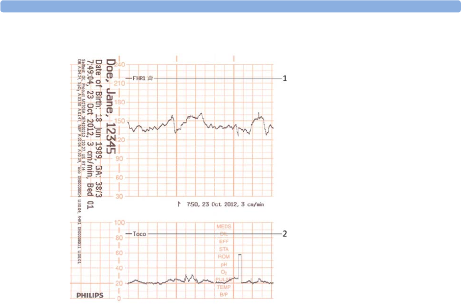
3 Basic Operation
57
The current monitoring modes (if any transducers are connected to the monitor) are printed.
Whenever a transducer's mode is changed, the following are printed:
• the time
• the date
• trace identification symbols
• the recorder speed
The monitor prints the time, date, recorder speed, and monitoring modes in the trace header when
first switched on, in a periodic time stamp every ten minutes after, and if the monitoring modes
change. The time stamp begins with the symbol shown below. The data is reprinted in the header if the
time and date are locally adjusted, or if an obstetrical information and surveillance system is connected
that readjusts the time and date automatically.
1Fetal heart rate label
2Uterine activity label
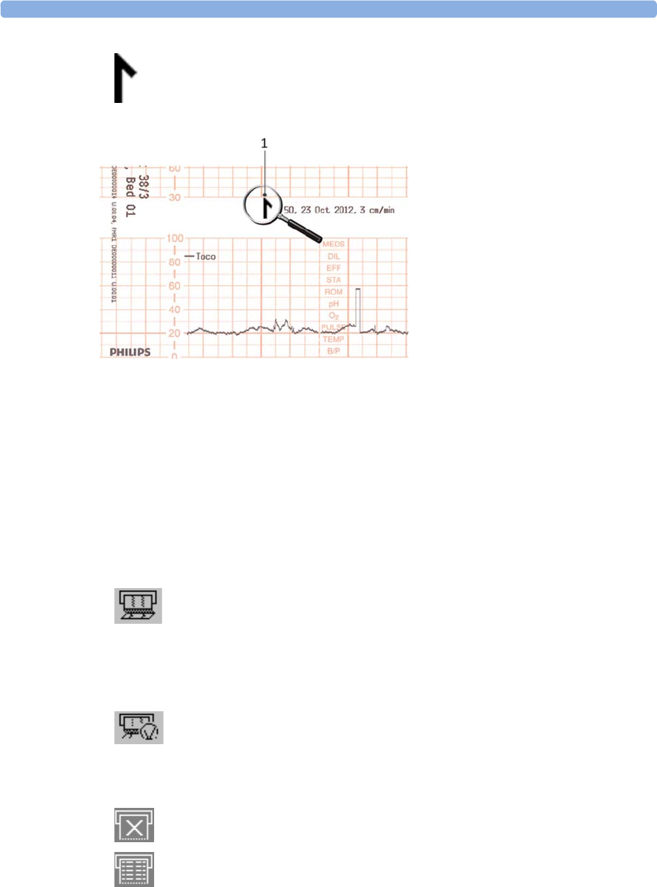
3 Basic Operation
58
The trace records maternal parameters also. When measuring noninvasive blood pressure, the
annotation is made at the end of the measurement. If the noninvasive blood pressure measurement
repetition time is short, the noninvasive blood pressure numeric may not always be printed.
The recording of notes (see “Entering Notes” on page 69) or time/date information may be
interrupted by connecting, or unplugging a transducer, or by a change in measurement-related setting
(for example, artifact suppression, Toco sensitivity, or alarm settings).
A new patient admission or a change to the paper scale setting stops all annotations, and prompts a
new vertical trace header to be printed.
To switch off the recorder:
1Either select
Start/Stop
from the
Fetal Recorder
menu.
2Or press one of the SmartKeys (depending on configuration): fetal recorder
Start/ Stop
or
Stop
Recordng
.
If your recorder is configured with
Confirmed Stop
on (a Configuration Mode setting), you will
need to confirm that you want to stop the recorder, before it will stop.
When the recorder is off, the "recorder off" status indicator is displayed in the bottom right-hand
corner of the screen: When the
Paper Save Mode
is set to
Off
the paper symbol shows an x mark,
and when
Paper Save Mode
is
On
the icon shows a paper trace icon.
1Time stamp printed every ten
minutes
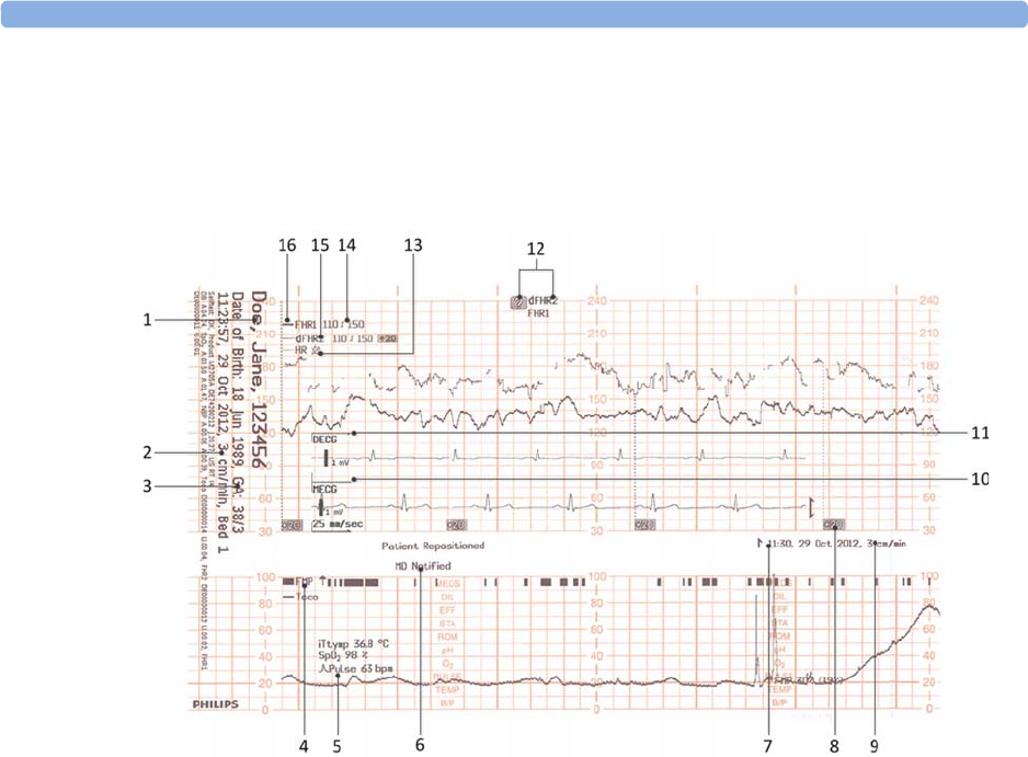
3 Basic Operation
59
Recording Elements
A variety of information can appear on the recorder trace. Here is a sample trace with some of the
most common elements and their meaning. Each trace header contains the last name and first name,
the patient ID, patient date of birth, the current date and time, patient's bed label, and the gestational
age of the pregnancy.
1Name, patient ID, date of birth, current date and time
2Recorder speed
3Gestational age and patient bed label
4FMP - Fetal Movement Profile
5Other measurements for the patient such as temperature, arterial oxygen saturation, and pulse
6Entered notes such as patient repositioned, or MD notified, or others
7Time stamp
8Trace separation
9Recorder speed
10 Maternal ECG
11 Direct ECG
12 Coincidence of heart rate detected
13 HR with Alarms Off symbol
14 Alarm Limits
15 dFHR2 (second fetal heart rate from DECG)
16 FHR1 (first fetal heart rate)

3 Basic Operation
60
Caution
The trace contains sensitive personal data. For information how to protect personal information, see
“Protecting Personal Information” on page 17.
Choosing Recorder Speed
You can choose a recorder speed of 1, 2, or 3 centimeters per minute (cm/min). The default setting is
3 cm/min.
The ACOG technical bulletin on FHR monitoring states that "accurate pattern recognition is difficult if not
impossible at 1 cm/min and that 1 cm/min is only recommended for more economic screening. When FHR
abnormalities arise, the faster recorder speeds will enhance FHR pattern recognition".
Additionally, because a change in recorder speed results in a change in the appearance of an FHR trace,
you are advised to ensure ALL monitors in your institution are set to the same speed.
To set the recorder speed (in Configuration Mode), see the Configuration Guide.
Advancing the Paper
You can advance the paper automatically to the next fold by pressing the
Paper Advance
SmartKey at
any time except during a stored data recording. This is also possible using the
Fetal Recorder
menu.
Marking an Event
You can record significant events on the trace paper (for example, when pain medication is
administered or when the mother changes position). The mother can use the remote event marker to
mark events herself. You connect the remote event marker to any free fetal sensor socket.
To mark an event on the trace paper, you can:
1Either select the
Set Marker
SmartKey.
2Or press the button on the optional remote event marker (989803143411). The remote event
marker is connected to the monitor via any fetal transducer socket.
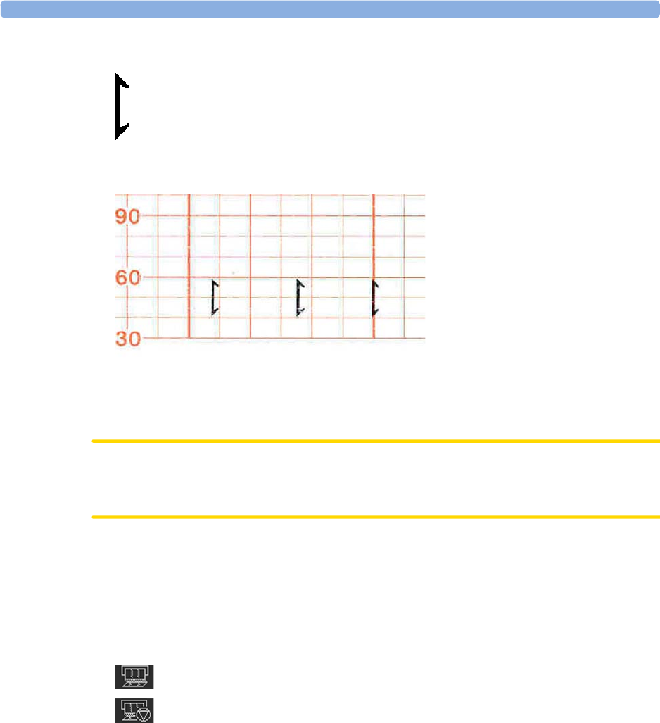
3 Basic Operation
61
A small arrow is printed on the heart rate scale on the trace paper.
This reflects exactly when the marker button was first pressed; keeping the button pressed has no
influence on the annotation.
Tearing Off the Paper
CAUTION
Never pull on the paper to advance it, as this can cause misalignment of the paper. Always tear off the
paper along the perforation.
FM40/FM50 The recorder's paper guide incorporates a tear-off edge, allowing you to tear off the trace paper cleanly
where you like (not necessarily at a fold). When you are not using the paper guide, always tear off the
paper along the perforation.
To tear off the trace paper after monitoring using the paper guide:
1If the recorder is running (the "recorder on" status indicator is displayed), turn off the recorder by
selecting the fetal recorder
Start/ Stop
SmartKey or the
Stop Recordng
SmartKey.
2Tear off the paper as shown in the picture. To ensure a clean tear, always tear in an upwards
motion, as indicated by the arrows. You can start tearing from the left or right (right-handed user

3 Basic Operation
62
shown). You may want to use both hands to guarantee that the paper is not misaligned during the
tear off.
3If you wish to tear off the paper at a fold, select the
Paper Advance
SmartKey, wait for the paper to
stop, then tear it off.
FM20/FM30 The FM20/FM30 does not have a paper guide. The procedure is the same as described for the FM40/
FM50 with the exception that you should advance the paper to a perforation.
If you wish to tear off the paper at a perforation, select the
Paper Advance
SmartKey, wait for the paper
to stop, then tear it off.
Paper-Out Indication
Each pack of paper has 150 pages. The monitor issues a paper-out warning in the status line at the
bottom of the screen, when there are five pages to go. If you switch on the recorder or press the
Paper
Advance
key when there are fewer than five pages remaining, it may take two pages before the alarm is
activated. Load a new pack in time.
If the recorder runs out of paper, an audible paper-out alarm is sounded, if so configured. See
“Loading Paper FM40/FM50” on page 65, and “Loading Paper FM20/FM30” on page 62 to learn
how to reload paper.
Fetal traces continue to be recorded into the monitor's backup memory, and can be retrieved and
printed completely if new paper is loaded within one hour, when the
Bridge Paperout
setting is enabled
in Configuration Mode. See “Recovering Traces on Paper” on page 257 for further information.
Loading Paper FM20/FM30
CAUTION
Using recorder paper that is not approved by Philips can result in accelerated paper fading and can
damage the thermal line printhead. This type of damage is not covered by warranty.
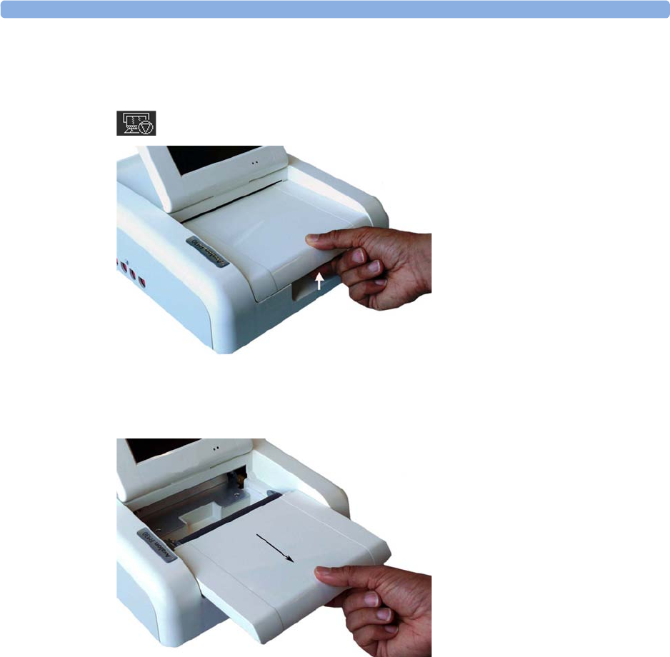
3 Basic Operation
63
FM20/FM30 To load a pack of paper:
1If the recorder is on, press the recorder
Start/ Stop
SmartKey or the
Stop Recordng
SmartKey to
turn it off before loading a new pack of paper.
2Press the paper table release to unlock the paper drawer and then pull the table forward to open it
fully.
3Lift out any remaining paper from the tray.
4Prepare to place the new pack of paper in the tray with the bottom side down. The bottom side is
indicated by the word STOP printed on the final page of the new pack.
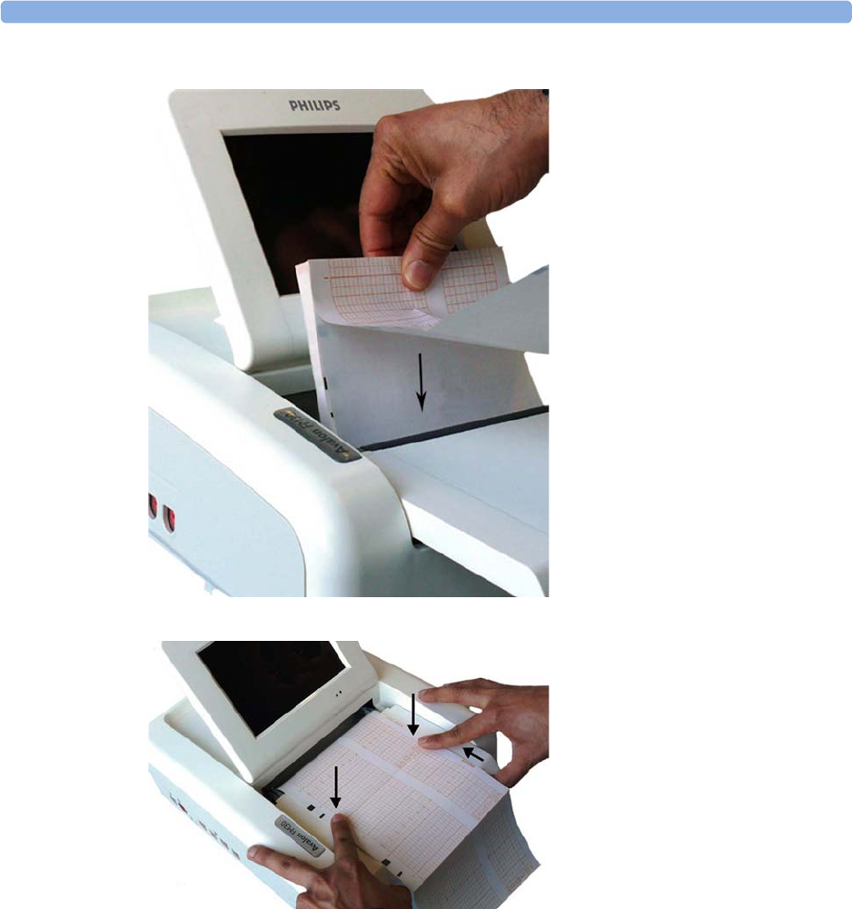
3 Basic Operation
64
5Unfold the top page of the pack and position the uterine activity scale on the right.
6Slide the pack into the tray.
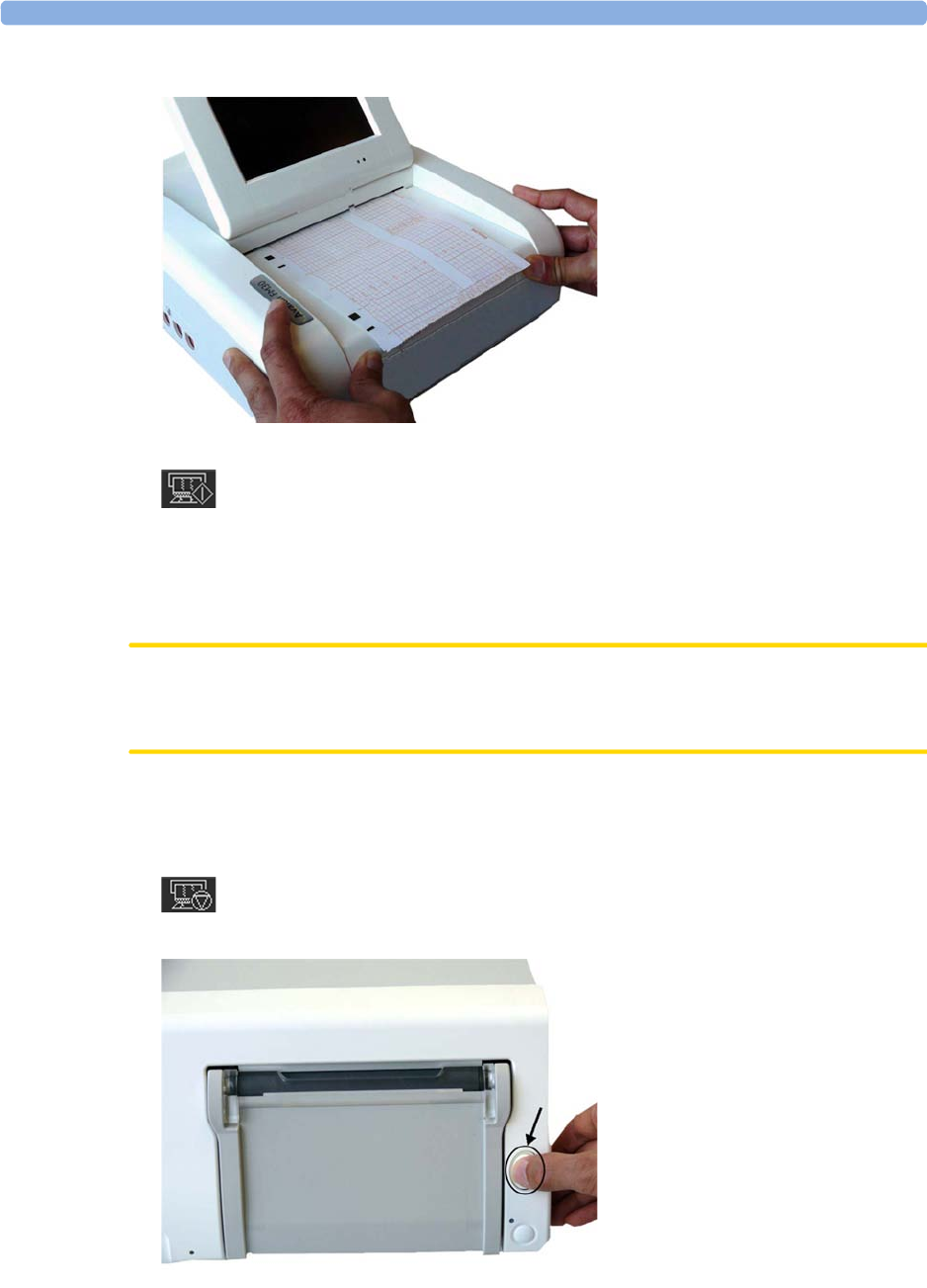
3 Basic Operation
65
7Push the paper drawer back until it "clicks" closed.
8Press the recorder
Start/ Stop
SmartKey or the
Start Recordng
SmartKey to switch on the recorder.
Annotations of trace information are printed on the trace paper (see “Switching the Recorder On and
Off” on page 56 for details).
Loading Paper FM40/FM50
CAUTION
Using recorder paper that is not approved by Philips can result in accelerated paper fading and can
damage the thermal line printhead. This type of damage is not covered by warranty.
FM40/FM50 To load a pack of paper:
1If the recorder is on, press the
Start/ Stop Rec
SmartKey or the
Stop Recordng
SmartKey to turn it
off before loading a new pack of paper.
2Press the paper eject button to open the paper drawer.
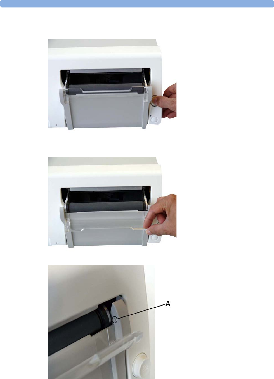
3 Basic Operation
66
3Lift out any remaining paper from the tray.
4Press and hold the paper eject button to partially eject the paper, thus making it easier to remove.
5Hinge the transparent paper guide forward. It is held in the closed position by a small protrusion
on each side of the holder.
A - Protrusion holds paper guide in closed position.
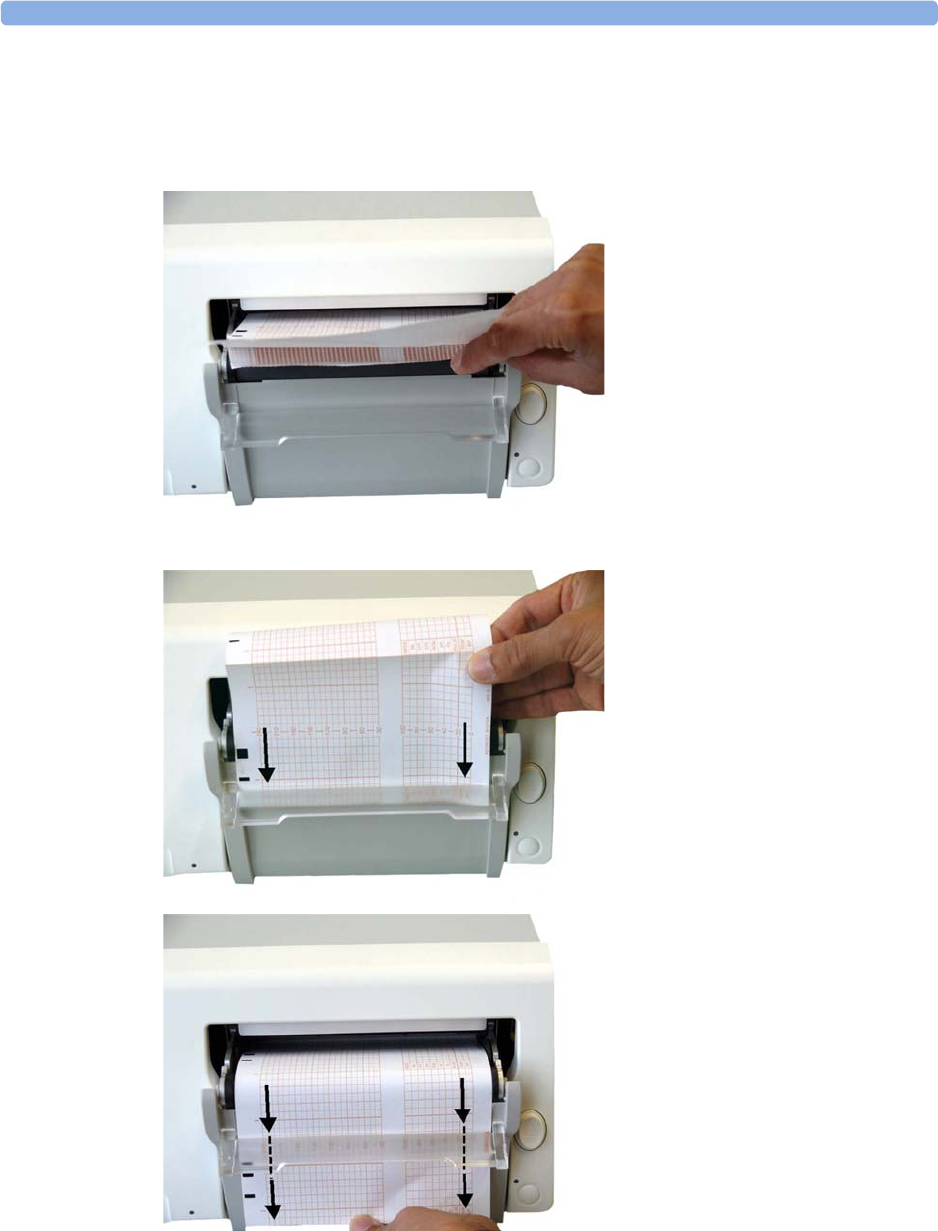
3 Basic Operation
67
6Prepare to place the new pack of paper in the tray with the bottom side down. The bottom side is
indicated by the word STOP printed on the final page of the new pack.
7Unfold the top page of the pack and position the uterine activity scale on the right.
8Slide the pack into the tray.
9Feed the paper evenly through the paper guide. Do not close the paper guide yet.
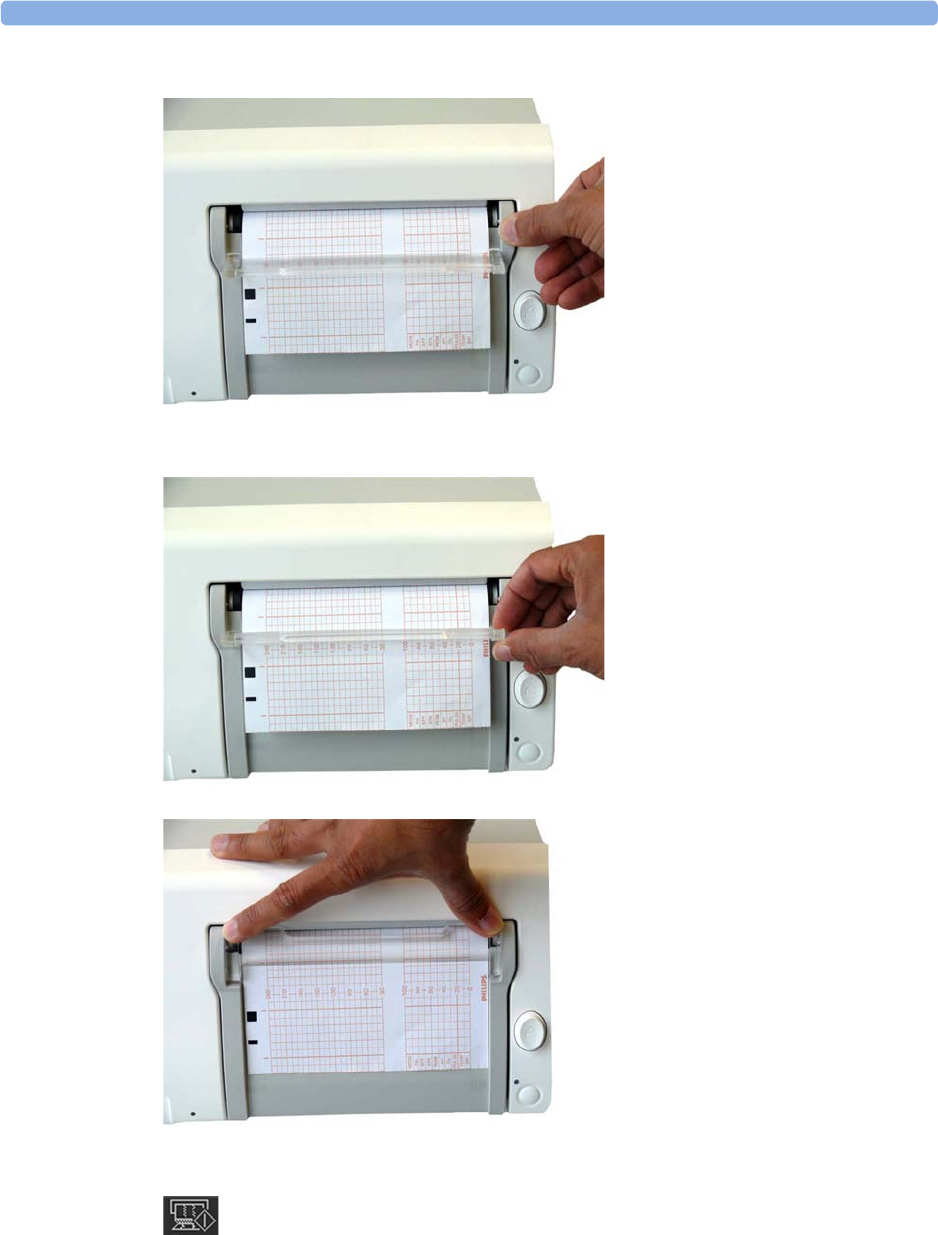
3 Basic Operation
68
10 Close the paper drawer.
11 Now close the paper guide.
12 Press the recorder
Start/ Stop
SmartKey or the
Start Recordng
SmartKey to switch on the recorder.
Annotations of trace information are printed on the trace paper (see “Switching the Recorder On
and Off” on page 56 for details).

3 Basic Operation
69
Entering Notes
Your monitor has a set of 15 factory pre-configured notes (see below). It is possible to edit these notes
in Configuration Mode (see the Configuration Guide). The maximum length of one single note is
30 characters.
To enter a note:
1Select the
Enter Notes
SmartKey to open the
Enter Note
menu.
2Scroll if necessary, then select the note you wish to enter. A confirmation dialog box opens:
3Select
Confirm
to enter the note. The note is then shown in the status line of the display, and is
annotated on the fetal trace if the fetal recorder is on.
4By default, notes are printed lengthwise in the direction of the trace, in the space between the FHR
grid and the uterine activity grid. If you prefer, you can configure the recorder to print across the
trace. You can change this in Configuration Mode.
The following are the pre-configured notes from which to choose:
1
Patient Repositioned
2
Vaginal Examination
3
MD Notified
4
Sitting
5
On Back
6
Left Lateral
7
Ambulating
8
Tocolytic Given
9
Membranes Ruptured
10
Amniotomy
11
Amniotic Fluid Clear
12
Amniotic Fluid Not Clear
13
Oxytocin
14
Urinary Catheter
15
Micro Blood Analysis
Up to two notes can be printed directly, and the monitor can temporarily store up to a further two
notes, and these are printed after the first two have been printed. Any further notes are discarded. For
example, if you enter six notes in quick succession, the first two notes you entered are printed right
away, the next two are stored in memory and then printed when the first two have been printed, and
the last two are discarded.
If the printing of two notes happens to coincide with the regular printing of the time stamp that takes
place once every ten minutes, the time stamp is delayed until the notes have finished printing.

3 Basic Operation
70
Typing Notes
Other than the pre-configured notes selectable in the
Enter Note
menu, a note can be typed in
manually.
To type a note:
1Select the
Enter Notes
SmartKey to open the
Enter Note
menu.
2Select
Type a note
and a window with a touch keypad opens.
3Type the note and select Enter. The typed note can be up to 30 characters long. The note is shown
in the status line of the display, and is annotated on the fetal trace if the fetal recorder is on.
NOTE
The typed note remains in the window until it is deleted by using the backspace button of the
keyboard.
Signal Quality
During monitoring, if the fetal heart rate signal quality fluctuates, and becomes poor, it does not
necessarily mean that the transducer needs repositioning. The fluctuation may be caused by fetal
movement. Allow time for the signal to stabilize before deciding whether to reposition the transducer
(ultrasound), or apply a new electrode (ECG). For the best trace quality, the signal quality indicator
should be full, indicating good signal quality, even though it may be possible to make traces at a lower
signal quality level.
After Monitoring
Wired and cableless transducers
1Discharge the patient.
2Remove the transducer from the patient and, using a soft tissue, remove any gel from it. Then
clean the transducers.
3Dock CL transducers to the base station so they can recharge.
4Tear off the paper at the fold. To avoid misalignment of the recorder mechanism, NEVER pull on
the paper to advance it, or try to tear it other than at a fold (unless using the paper guide with the
FM40/FM50).
5Switch off the monitor.
NOTE
If an Avalon CL base station is connected to your FM20/30 monitor, do not turn off the monitor if
you need to recharge the batteries of the CL transducers. They can only be recharged if the FM20/30
monitor is on. If an Avalon CL base station is connected to an FM40/50 at the Telemetry ports in the
rear, the batteries of the CL transducers can be recharged while the monitor is not switched on. If you
disconnect a base station from a fetal monitor when the CL transducers are not fully charged, the base
station starts beeping. If you want to still disconnect it, confirm your choice by pressing the Standby
key of the base station, and the beeping stops.

3 Basic Operation
71
Switching the Monitor to the Standby Screen
To switch the monitor to the Standby screen:
Either
1Select the
Monitor Standby
SmartKey.
Or
1Enter the
Main Setup
menu using the SmartKey.
2Select
Monitor Standby
.
3Pressing any key or selecting any field on the screen will resume monitoring.
Disconnecting from Power
FM20/30
To disconnect the monitor from AC power, switch the monitor off using the On/Off switch located
on the right side of the device, or unplug the power cord from the AC mains socket.
FM20/FM30 with Battery Option and FM40/FM50
The On/Standby button does not disconnect the monitor from the AC power source. To disconnect,
unplug the power cord from the AC mains socket. Note that if the power cord is unplugged from the
AC mains socket before the monitor is put into Standby, a beeper is activated. The beeper warns you if
the monitor is accidentally disconnected from AC mains.
External Power Supply for the Avalon CL Base Station
To disconnect, unplug the power supply from the AC mains socket. Note that if the power supply is
unplugged from the AC mains socket before all CL devices are fully charged, a beep is issued. To
confirm the disconnection from power, and to silence the beep, press the On/Standby button of the
CL base station.
Power On/Power Off Behavior
The general rules determining the behavior of the fetal monitors when connected to, or disconnected
from power are as follows:
• A fetal monitor that was switched on prior to a temporary power loss, switches on again when
power is restored.
• A fetal monitor that was switched off prior to a temporary power loss, remains off when power is
restored.
• When AC mains power is lost, a battery powered monitor (FM20/30) continues to run without
interruption on battery power.

3 Basic Operation
72
Monitoring After a Power Failure
• A fetal monitor that was switched on prior to a temporary power loss, switches on again when
power is restored.
• A fetal monitor that was switched off prior to a temporary power loss, remains off when power is
restored.
• If the fetal monitor is without power for less than one minute, monitoring will resume with all
active settings unchanged.
• If the fetal monitor is without power for more than one minute, the behavior depends on your
configuration.
–If
Automat. Default
is set to
Yes
, the default profile will be loaded when power is restored.
–If
Automat. Default
is set to
No
, all active settings are retained, if power is restored within
48 hours. The
Automat. Default
setting is made in Configuration Mode.
Troubleshooting
Problem Possible Causes Solutions
Light or no trace Wrong paper Use recommended paper
Dirty printhead Clean printhead, see “Cleaning the
Print Head” on page 273
FM20/30 only: Paper misaligned due
to drawer not being correctly shut
Shut the drawer fully, pushing evenly
with both hands
End of paper noted when pack not
finished
Bad paper feed or wrong paper Check paper feed and use
recommended paper
Check Paper
INOP is displayed INOP messages always indicate
equipment problems
See “Patient Alarms and INOPs” on
page 129
FetRec Equip Malf
INOP is displayed
Paper End
INOP is displayed
Wrong Paper Scale
INOP is displayed

4
73
4Cableless Monitoring
Avalon CL Transducer System
The Avalon CL Fetal Transducer System lets you monitor the patient continuously with cableless
transducers during the antepartum period, labor, and delivery.
You can monitor the fetal heart rate (FHR):
• Using noninvasive CL Ultrasound transducers
• Invasively, using the CL ECG/IUP transducer or CL Toco+ MP transducer with a fetal scalp
electrode
• Noninvasively, with the CL F&M Pod
The uterine activity can be monitored using:
• Externally, using the CL Toco+MP transducer
• Externally, using the CL F&M Pod
• Invasively, using the CL ECG/IUP transducer or CL Toco+MP with an IUP catheter
The fetal and maternal parameters are measured and transmitted via radio frequency from the
CL transducers and CL Pods to the CL base station, eliminating the need for patient cables. With the
Avalon CL Transducer System, you can monitor a single fetus, twins, and triplets.
The Avalon fetal monitor (FM20-FM50) connected to the CL base station displays and records the
parameters. All the CL transducers and the CL F&M Pod are watertight. The IntelliVue CL Pods
should not be immersed in water. You can continuously monitor patients in a bath or shower using the
CL Toco+MP and the CL Ultrasound transducers, the CL F&M Pod should not be used during a bath.
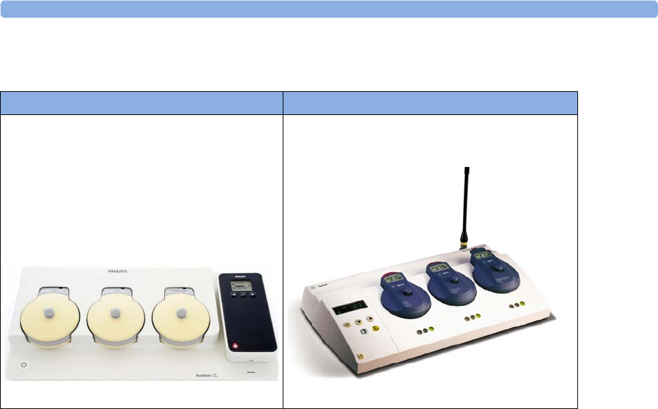
4 Cableless Monitoring
74
Basics of Cableless Systems
Assigning Cableless Devices
The cableless devices of the Avalon CL are assigned by simply docking them at the base station
connected to the patient’s fetal monitor. See the Avalon CTS Instructions for Use for the assignment
of the CTS transducers.
Activating Cableless Devices
The CL devices of the Avalon CL are activated by picking them up from the base station. If the
CL devices are activated, a corresponding symbol is displayed on the fetal monitor screen next to the
numeric of the measurement. See the Avalon CTS Instructions for Use for the activation of the
CTS transducers.
Deactivating Cableless Devices
The CL devices of the Avalon CL are deactivated by redocking them at a base station. To deactivate all
cableless devices at once, press the Standby key of the Avalon CL base station. See the Avalon CTS
Instructions for Use for the deactivation of the CTS transducers.
Unassigning Cableless Devices
The CL devices of the Avalon CL are unassigned by manually removing them in the corresponding
setup menu from the group of assigned cableless devices, or by unassigning them directly in the
Tele
Info
window. See the Avalon CTS Instructions for Use for the unassignment of the CTS transducers.
Avalon CL Transducer System Avalon CTS Transducer System

4 Cableless Monitoring
75
Twins and Triplets Support
Configuration of Cableless Systems
You have to configure the radio channels of the Avalon CL and Avalon CTS transducer system for
communication to work, and not to interfere with any other telemetry devices.
The configuration of a connected Avalon CL system is done in Configuration Mode or Service Mode
of the fetal monitor. Service Mode functions can be used to identify channel assignment conflicts in
the hospital environment. The configuration should be carried out by authorized and qualified service
personnel, either by the hospital's biomedical department, or by Philips Support.
For a detailed description of the configuration see the Avalon CL Service Guide and the Fetal Monitor
Configuration Guide. For details regarding the configuration of a connected Avalon CTS system see
the Avalon CTS Service Guide.
Fetal Movement Profile
When using an Avalon CL or Avalon CTS you should be aware that monitoring FMP is not
recommended when the mother is likely to move, and you should disable Fetal Movement Profile
(FMP) on the fetal monitor (
Fetal Movement
Off
) if the mother is walking. Maternal movements are
likely to create artifact in the FMP output. See also “Switching FMP On and Off” on page 171, the
sections “Cableless Monitoring - Important Considerations” on page 167, and “Fetal Movement
Profile” on page 170.
Twins and Triplets Singletons only
Avalon CL Transducer System and
CL transducers
Avalon CTS System
Avalon CL Transducer System with
CL Fetal & Maternal Pod
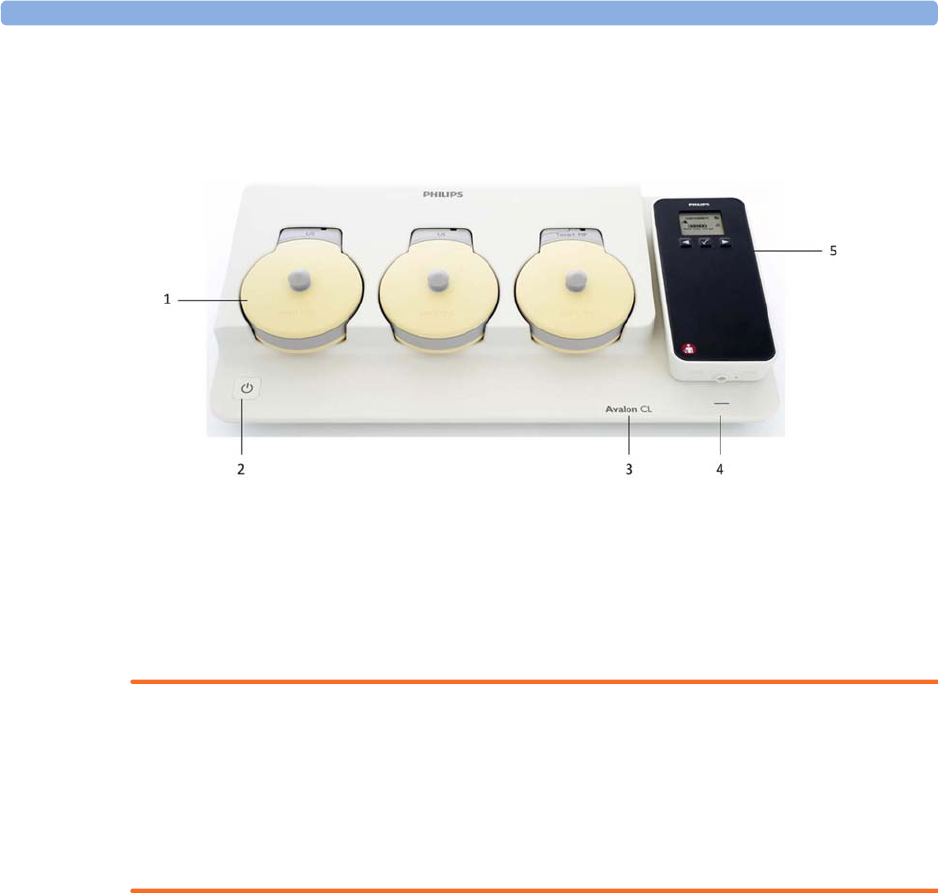
4 Cableless Monitoring
76
Getting to Know Your Avalon CL
Front
1Transducer docking slots
2On/Standby button with LED
3Device label
4LED for optional cableless Pods
5Docking slot for cableless Pods
WARNING
• To avoid magnetic interference affecting the mode of the pacemaker, ensure that the Avalon
CL base station does not come into close contact with implanted pacemakers.
• This equipment generates, uses, and radiates radio-frequency energy, and if it is not installed and
used in accordance with its accompanying documentation, may cause interference to radio
communications. Operation of this equipment in a residential area may cause interference, in
which case you must take whatever measures may be required to correct the interference.
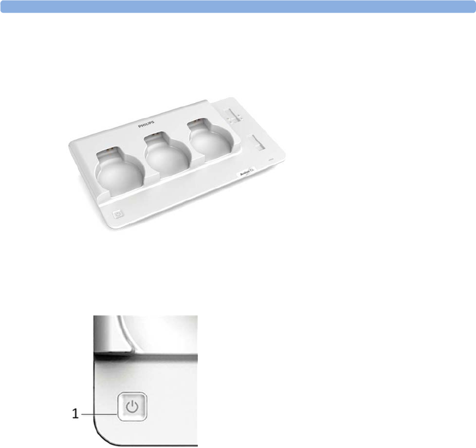
4 Cableless Monitoring
77
Docking Slots for Cableless Transducers
The Avalon CL base station has three docking slots to hold the CL transducers. The transducers are
charged while docked. The base station has a built-in radio interface with an integrated antenna to
communicate with the transducers.
On/Standby Button
Pressing the On/Standby button switches the Avalon CL base station between the two modes On and
Standby.
If you switch the base station to On, the LED button lights up green. The base station is ready for use.
When the transducers are picked up from their docking slot, the base station sets up the radio
communication to the CL transducer automatically. Wired transducers connected to the fetal monitor
are disabled, and the antenna symbol for the CL transducer is displayed on the screen of the fetal
monitor.
If you switch the base station to Standby, the LED button turns off. The base station is now in
Standby mode. No radio communication occurs, any existing radio communication is stopped.
If the LED of the On/Standby button turns red, it indicates a technical problem has occurred that
needs your attention. Check your monitor for a possible related INOP message.
1On/Standby button
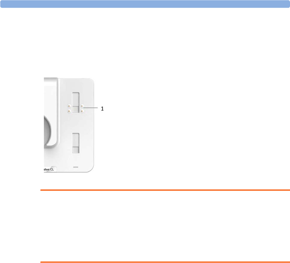
4 Cableless Monitoring
78
Docking Slot for Cableless Measurement Pods
The Avalon CL base station has one docking slot to hold a CL F&M Pod or an IntelliVue CL Pod.
The CL Pod is charged while docked. The LED under the docking slot indicates the battery status of
the CL Pod. The base station has a built-in short range radio interface with an integrated antenna to
communicate with the CL Pod.
WARNING
Short range radio connections are subject to interruption due to interference from other radio sources
in the vicinity, including microwaves, bluetooth devices, WLAN devices (802.11b,g,n), and cordless
phones. Depending on the strength and duration of the interference, the interruption may occur for an
extended period. A loss of connection, due to moving out-of-range, interference, or for other reasons,
is indicated with a
No Host Monitoring
INOP (here the host is the fetal monitor) on the NBP or
SpO2 Pods, or a
cl NBP Disconnect
or
cl SpO Disconnect
INOP at the fetal monitor. Correct channel
configuration is important, see the Configuration Guide for details.
Audio Signal CL Base Station
The Avalon CL base station has two audio signals:
• If the base station issues a descending tone sequence, the attempt to set up radio communication
to a CL transducer or CL Pod has failed.
• The base station issues a permanent beeping tone if it is disconnected from a fetal monitor, or if
the FM20 or FM30 monitor is switched off, and the base station has transducers or a Pod
currently docked that need to be recharged.
Alarming is only available at the Avalon Fetal Monitor, not at the Cableless Measurement Devices, see
the Instructions of Use for the IntelliVue Cableless Measurements.
1Docking slot for CL Pods
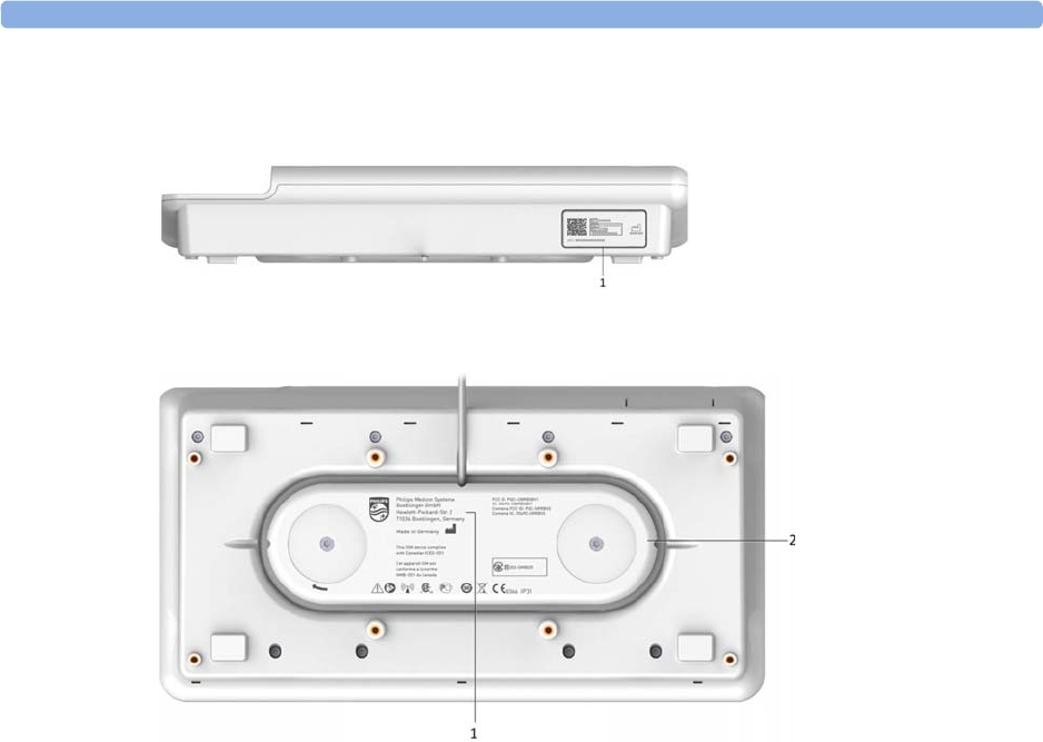
4 Cableless Monitoring
79
Rear and Bottom
1Name plate
1Manufacturer label
2Cable reel
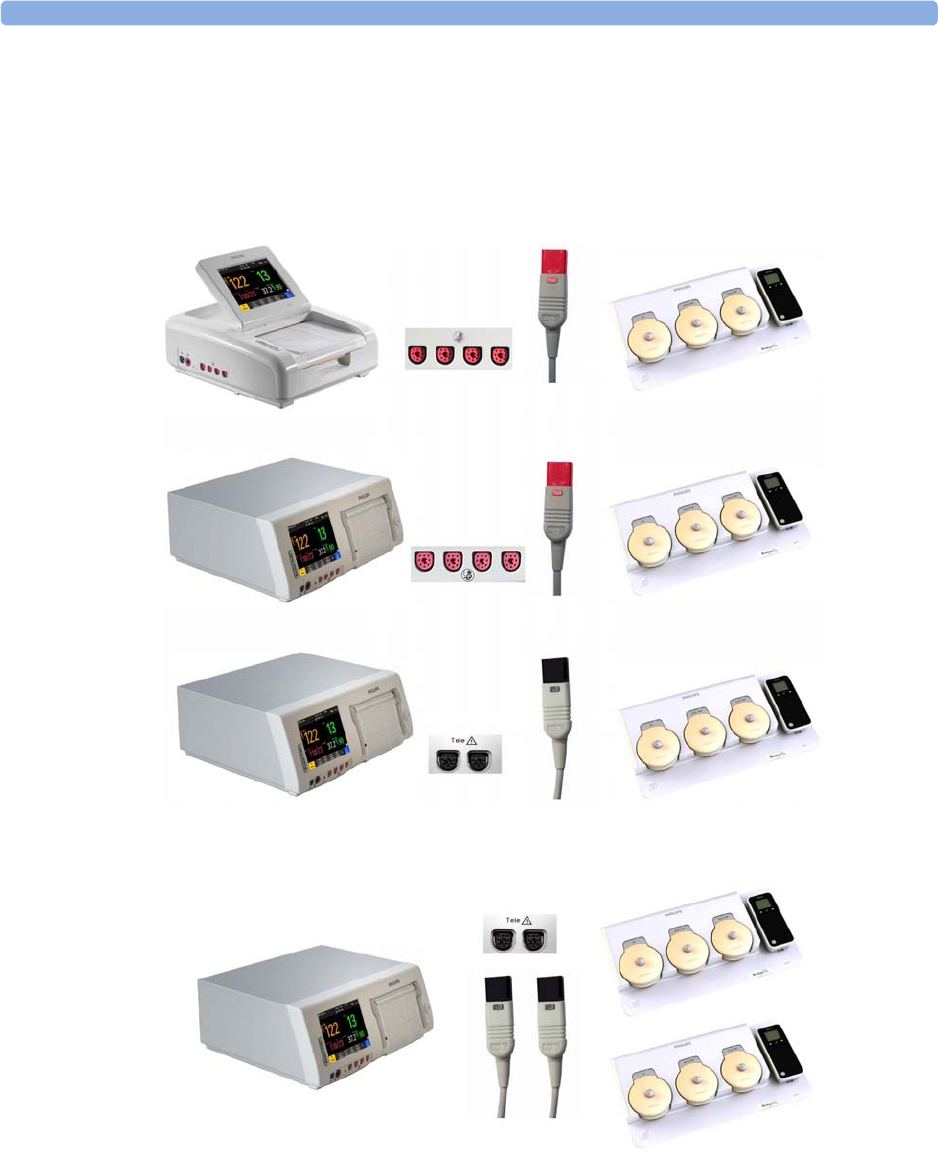
4 Cableless Monitoring
80
Connection Options
The fetal monitors FM20/FM30 and FM40/FM50 are compatible with the Avalon CL and Avalon
CTS Transducer Systems. Regard the following points for cableless monitoring:
• You can connect one Avalon CL base station with a red connector to an FM20/FM30 or an
FM40/FM50 (fetal socket), or one Avalon CL base station with a black connector to an FM40/
FM50 (telemetry socket).
• You can connect two Avalon CL base stations with black connectors to an FM40/FM50
(telemetry sockets)
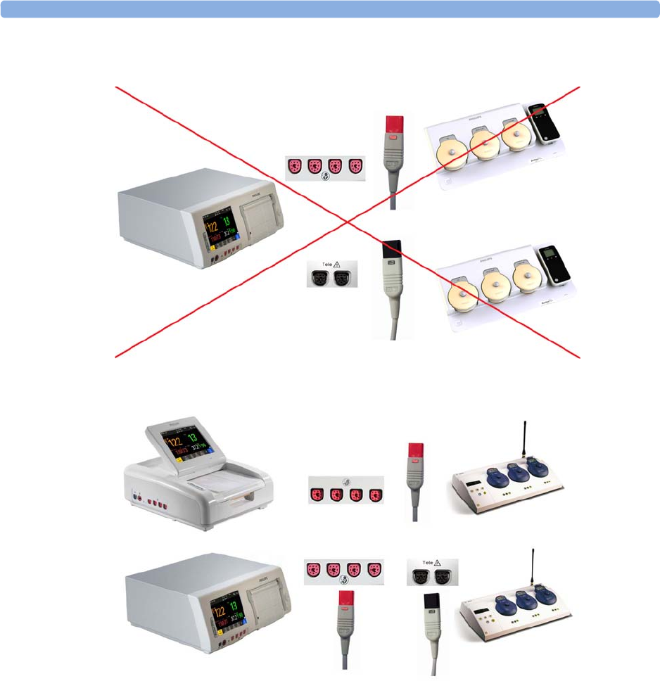
4 Cableless Monitoring
81
•You cannot connect two Avalon CL base stations to an FM40/FM50, if one Avalon CL base
station has a red connector, and the other Avalon CL base station has a black connector.
• You can connect one Avalon CTS system to an FM20/FM30 or FM40/FM50 at a time (either
fetal or telemetry socket).
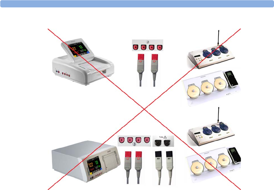
4 Cableless Monitoring
82
•You cannot connect an Avalon CTS and an Avalon CL at the same time to the same fetal monitor.
• Monitoring a multiple pregnancy using cableless transducers is supported by the Avalon CL system
only.
• Using a mixture of wired and cableless fetal transducers is not supported. You can use either wired
or cableless fetal transducers.
• If you cannot get sufficient signal quality using Avalon CTS transducers, switch to wired
transducers.
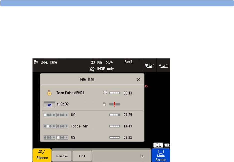
4 Cableless Monitoring
83
Connecting Two CL Base Stations to an FM40/50 Monitor
Two base stations can be connected to an FM 40/50 fetal monitor at the rear black telemetry ports. At
both base stations CL transducers and CL Pods can be assigned, activated, and redocked for charging.
The base stations work as one extended system together. Pressing the Standby key of either base
station, puts both base stations in Standby mode. The
Tele Info
window shows both base stations in
operation.
External Power Supply (Option K60)
In combination with the optional external AC power supply an Avalon CL base station serves only as
a charging station for Avalon CL transducers and IntelliVue CL Pods, and all radio communications
are disabled. The On/Standby button of the base station lights up white in this operation mode. The
charging indication of the LEDs of the docked CL transducers and the IntelliVue CL Pods remain the
same as described in the sections “Cableless Transducer LED Indication” on page 86 and “Battery
Status LED for CL Pods” on page 93.
When a transducer is picked up from the base station after charging, it needs to be activated for
monitoring by docking it on a CL base station connected to the patient's fetal monitor.
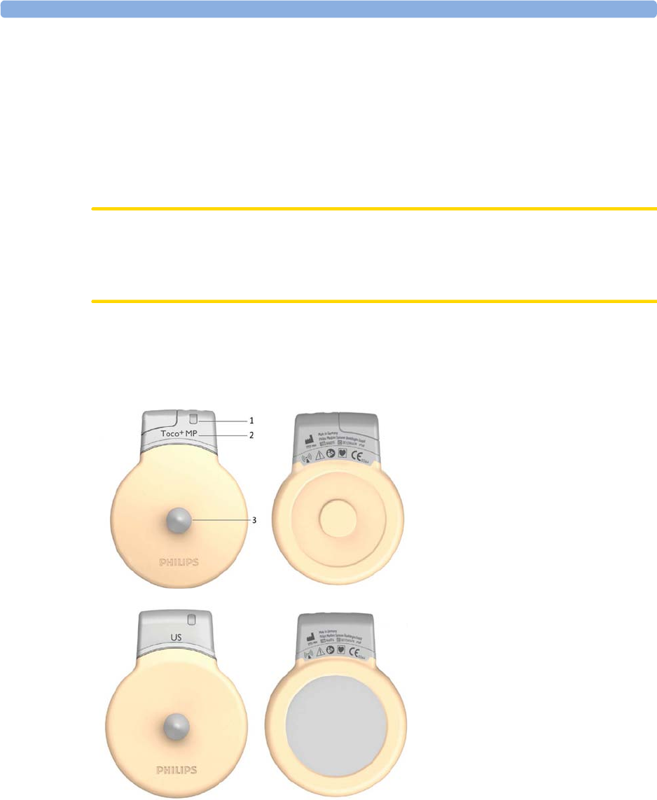
4 Cableless Monitoring
84
Cableless Transducers
The cableless Avalon CL transducers have a built-in radio interface with an on-board, integrated
antenna. The fetal monitor connected to the Avalon CL base station can control the transducer using
radio communication. The CL transducer transmits measured values, alarms, and status information to
the fetal monitor.
The CL transducers are assigned by simply docking them at the Avalon CL base station. If they are
picked up from their docking slot at the base station, they are automatically activated.
CAUTION
To ensure the correct assignment of CL transducers to the fetal monitor in use, always dock them at
the base station connected to that fetal monitor before use. This is particularly important when you
add an additional CL transducer that was previously docked at another base station.
NOTE
Avoid dropping the transducers.
1Transducer finder LED - lights
up on the transducer providing
the measurement source.
2CL Toco+ MP transducers
(capable of providing the
maternal pulse measurement)
3Belt button
CL Ultrasound transducer
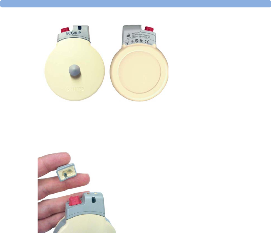
4 Cableless Monitoring
85
Connector Cap for the CL Toco+ MP Transducer
The CL Toco+ MP transducer is delivered with a connector cap covering the MECG/DECG/IUP
connector. The connector cap is designed to cover the connector, not to protect it from water. (The
connector itself is water-proof and may be immersed in water).
CL ECG/IUP transducer
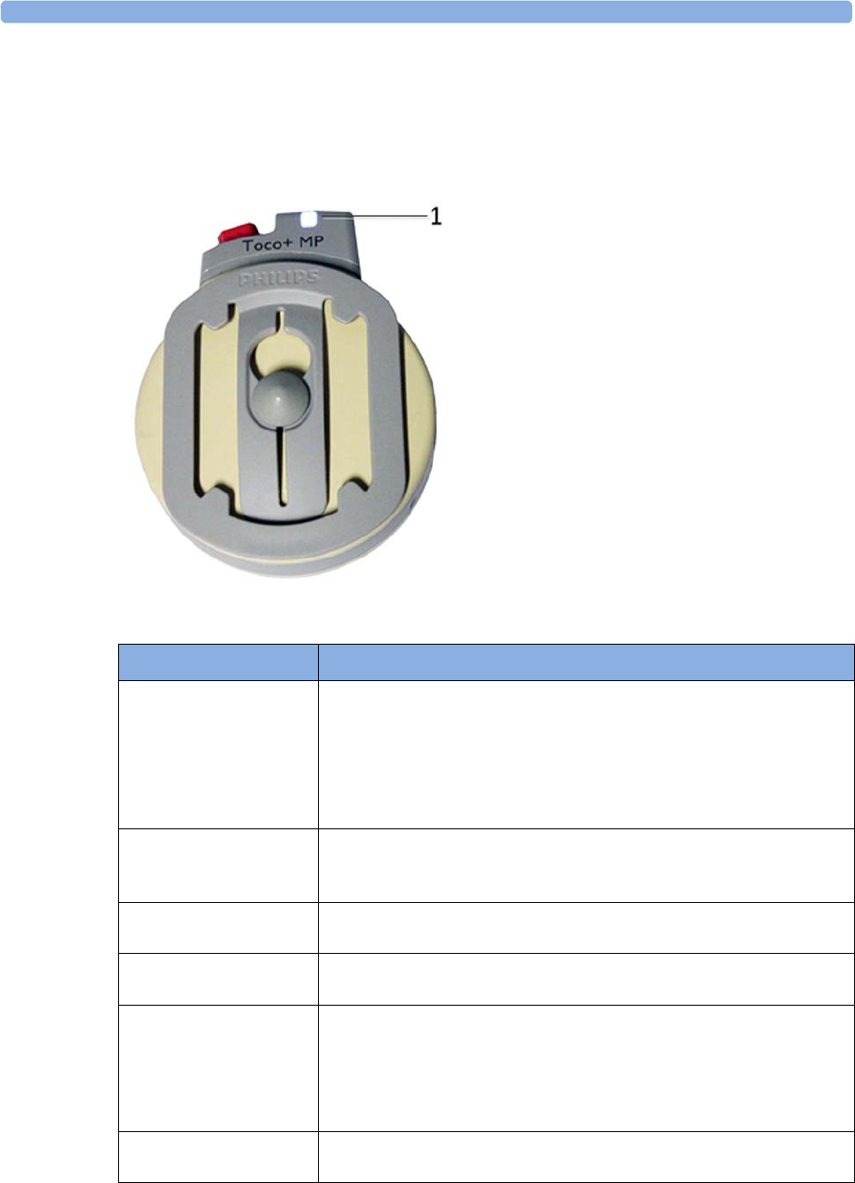
4 Cableless Monitoring
86
Cableless Transducer LED Indication
The cableless transducers have a multi-color LED that indicates the status of the transducer with
specific colors. This LED remains visible when the transducer is correctly attached to the transducer
belt (Philips standard belt).
1LED
LED Status Meaning
White The LED lights up to identify the transducer among other transducers,
and to easily verify the correct transducer assignment (transducer finder).
The transducer finder LED is controlled by the fetal monitor. Press the
numerics to identify the corresponding transducer.
The LED also lights up when the mother is paged with the
Call Patient
SmartKey.
White one short blink The LED shortly lights up to indicate that the transducer successfully
opened a radio communication with the base station and that it is ready to
use.
Green The LED lights up green when the transducer is fully charged and docked
at the base station.
Yellow The LED lights up yellow when the transducer is charging and docked at
the base station.
Red The LED flashes red when the transducer is out of battery and has to be
recharged.
When a docked transducer performs an update, the LED will blink fast
red for about 1 minute. In this case, do not remove the transducer until
the LED lights up green or yellow again.
Cyan The LED lights up cyan to indicate a technical problem that needs your
attention. Check your fetal monitor for a related INOP.

4 Cableless Monitoring
87
Audio Signal CL Transducers
The Avalon CL transducers have three audio signals:
• If an ascending tone sequence is played three times, the transducer was triggered by the fetal
monitor to page the patient wearing it, or to locate a not docked transducer.
• If the CL transducer's battery is empty, the transducer issues three beeps in intervals.
• An INOP tone indicates that the transducer has detected a technical problem (INOP). Check your
fetal monitor for a related INOP message.
Standard Radio Range of CL Transducers
The CL transducers have an operating range around the base station of at least 100 m/300 ft in the
line of sight. Obstructions such as walls, metal doors, elevators, and other environment structures can
lead to signal loss. The CL symbol indicator and the
Tele Info
window on the monitor's display (see
“Screen Elements” on page 39 and “Tele Info Window” on page 94) provide information on the
status of the signal strength.
When a patient is approaching the end of range, the US sound is replaced by an artificial QRS sound
(like DECG), and the DECG and MECG waves are no longer displayed on the monitor.
Out of Range
If the patient walks out-of-range, the CL transducer LED lights up cyan and every 16 seconds a two-
tone audio signal is emitted. At the monitor the INOP e.g.
cl US Disconnect
is issued. Inform the
patient to return to the CL base station, when a CL transducer starts beeping.
Radiated Transmission Power
The Avalon CL transducers provide all the benefits and flexibility of cableless operation, but do so
with an effective radiated transmission power significantly less than that of a typical remote controlled
child’s toy or mobile phone.
Extended Range Radio
Using the optional CL Wide Range Pod extends the radio range of the CL transducers and the
CL Pods to the local WLAN infrastructure. If the CL Wide Range Pod is active, the US sound is
replaced by an artificial QRS sound (like DECG), and the DECG and MECG waves are no longer
displayed on the fetal monitor. Numerics, alarms, and traces are shown at the fetal monitor as usual.
See also “CL Wide Range Pod” on page 91.
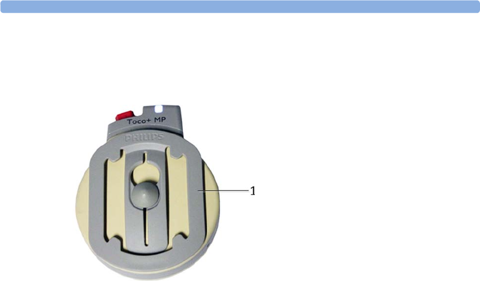
4 Cableless Monitoring
88
Using CL Transducers with a Belt Clip
The Avalon CL transducers can also be used with an optional belt clip to be ordered separately
(989803184851).
1Avalon CL belt clip
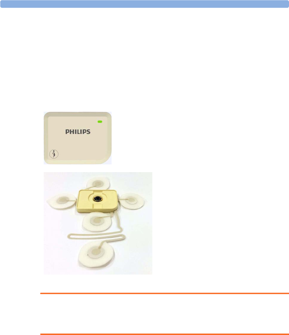
4 Cableless Monitoring
89
CL Pods
CL Fetal & Maternal Pod
The CL F&M Pod provides measurement values for FHR, Toco, and HR. It communicates them to
the fetal monitor using short range radio (SRR). It is controlled via SRR from the Avalon CL base
station and the connected fetal monitor.
The CL F&M Pod is assigned by docking it at the Avalon CL base station. Before monitoring, the
CL F&M Pod is mounted on a single-use electrode patch, and held in place by integrated magnets.
When the CL F&M Pod is active, the wired transducers connected to the fetal monitor are disabled.
WARNING
The CL Fetal & Maternal Pod has been validated with a gestational age of >36 weeks with patients in
labor. It is only intended for singleton pregnancies. If the measurement signals are not good or in any
way suspicious, use other means of monitoring (CL transducers or wired transducers).
CL F&M Pod
CL F&M Patch
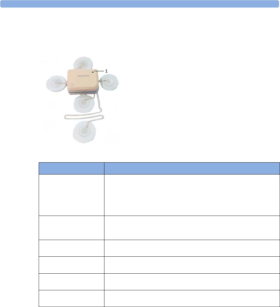
4 Cableless Monitoring
90
CL Fetal & Maternal Pod LED Indication
The CL F&M Pod has a multi-color LED that indicates the status of the CL F&M Pod with specific
colors.
Audio Signal CL Fetal & Maternal Pod
The Avalon CL F&M Pod has three audio signals:
• If an ascending tone sequence is played three times, the CL F&M Pod was triggered by the fetal
monitor to page the patient wearing it, or to locate a not docked CL F&M Pod.
• If three beeps are issued at intervals, the CL F&M Pod's battery is empty.
• An INOP tone indicates that the CL F&M Pod has detected a technical problem (INOP). Check
your fetal monitor for a related INOP message.
1LED
LED Status Meaning
White The LED lights up to identify the CL Pod, and to easily verify the correct
assignment (finder). The finder LED is controlled by the fetal monitor.
Select the numerics to identify the corresponding CL Pod.
The LED also lights up when the mother is paged with the
Call Patient
SmartKey.
White, one short blink The LED briefly lights up to indicate that the CL Pod successfully
opened a radio communication with the base station and that it is ready to
use.
Green The LED lights up green when the CL Pod is fully charged and docked at
the base station.
Yellow The LED lights up yellow when the CL Pod is charging and docked at the
base station.
Red The LED flashes red when the CL Pod's battery is empty, and has to be
recharged.
Cyan The LED lights up cyan to indicate a technical problem that needs your
attention. Check your fetal monitor for a related INOP.
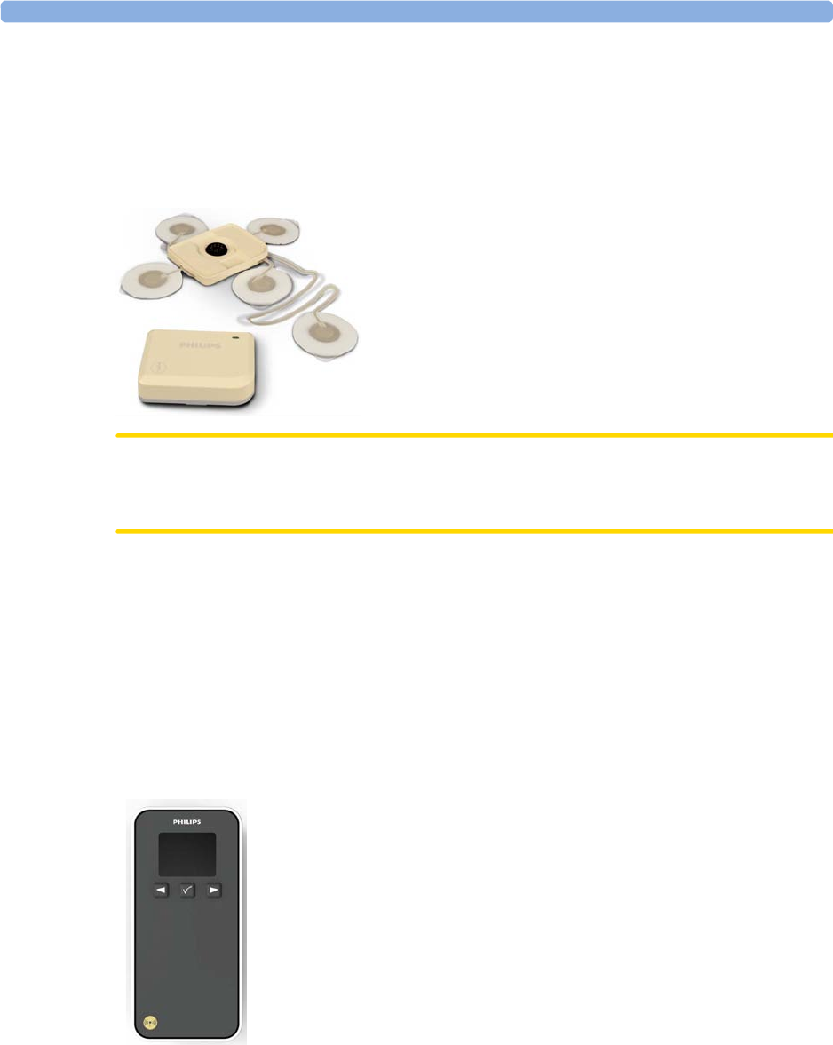
4 Cableless Monitoring
91
CL Fetal & Maternal Electrode Patch
The single-use disposable adhesive electrode patch holds the CL F&M Pod at the intended application
site on the abdomen of the patient. The electrode patch has five adhesive electrodes. The CL F&M
Pod is held in place during monitoring with magnetic contacts, and a connector. The electrode patch
and the CL F&M Pod can only be used together and within the Avalon Cableless Transducer System
solution for monitoring.
CAUTION
The electrode patch is single-patient use only, do not reuse the electrode patch on another patient to
avoid possible cross-infection.
CL Wide Range Pod
The Avalon CL Wide Range Pod is a battery-powered auxiliary network device that converts the SRR
and OB radio technology of Avalon CL transducers and the CL Pods into WLAN technology. This
allows data from the measurement devices to be transmitted to a fetal monitor while the patient is
ambulating.
The Avalon CL Wide Range Pod is a mobile device which can be worn by the patient or by an
attending caregiver. The display on the CL Wide Range Pod shows only technical data that may be
useful for troubleshooting system problems.
CL Wide Range Pod
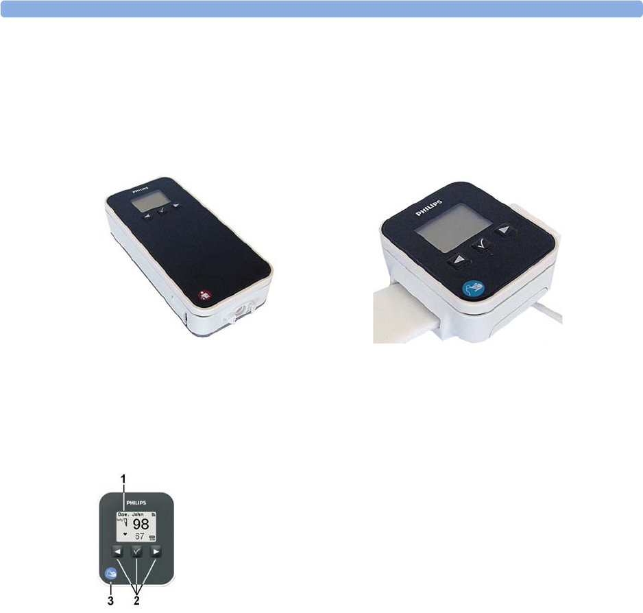
4 Cableless Monitoring
92
IntelliVue CL Pods
The two IntelliVue CL Pods provide measurement values for SpO2 and NBP on the built-in display,
and communicate them to the fetal monitor using short range radio (SRR). They are controlled with
SRR from the Avalon CL base station and the connected fetal monitor.
The maternal measurement pods are assigned by docking them at the Avalon CL base station.
The CL SpO2 Pod and the CL NBP Pod have an LCD display and three keys for basic operation e.g.
to assign the device to a patient:
For further details, see the IntelliVue Cableless Measurements Instructions for Use.
CL NBP Pod CL SpO2 Pod
1Integrated LCD display
2Hardkeys
3Measurement identifier
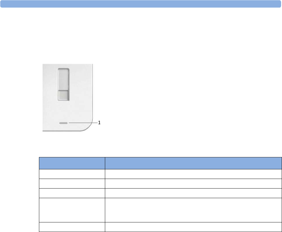
4 Cableless Monitoring
93
Battery Status LED for CL Pods
The CL Pods do not have their own battery status LED, but a small battery gauge on their display. On
the Avalon CL base station, the battery status LED for the CL Pods is located directly under the
docking slot.
The battery status LED shows five different states:
Audio Signal CL Pods
The CL Pods have audio signals to let you know when a battery has to be recharged. If a CL Pod's
battery is empty, the CL Pod issues three beeps at intervals.
Calling Patients
To call a patient currently not near the fetal monitor and base station, select the SmartKey
Call Patient
at the fetal monitor. The base station will then select one transducer, or the CL F&M Pod if it is
assigned and active, to emit the tone sequence to notify the patient. Inform the ambulating patient, if
the cableless device is issuing any beeping sounds, to return to the room with the fetal monitor.
1Battery status LED for CL Pods
Status Meaning
Green The docked CL Pod is fully charged.
Yellow The docked CL Pod is charging.
Yellow blinking The communication is established with the docked CL Pod.
Cyan Indicates that the docked CL Pod or the charging slot has a technical
problem that needs your attention. Check your fetal monitor for a related
INOP message.
Off The battery status LED is off, when no CL Pod is docked.
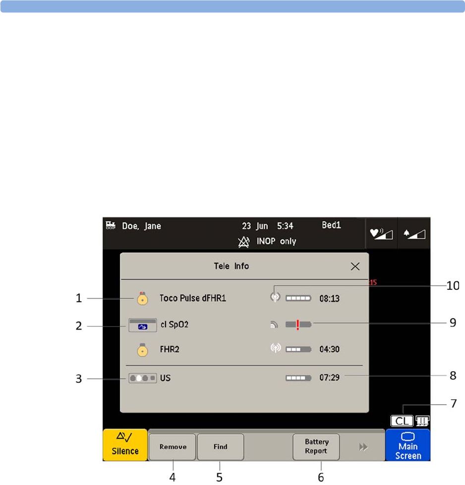
4 Cableless Monitoring
94
Telemetry
Tele Info Window
The
Tele Info
window of the fetal monitors allows you to manage the Avalon CL or CTS system.
Below is an exemplary view of the
Tele Info
window. Your window may differ depending on the status
of the connected system.
To open the
Tele Info
window, you can:
1Configure a
Tele Info
SmartKey to open the window,
2select the CL symbol on the main screen, or
3select the
Main Setup
and then
Tele Info
.
1CL transducer symbol assigned with the parameter labels
2Cableless measurement symbol and equipment ID
3Base station symbol with docking indication (the white slot indicates a charging transducer)
4Key
Remove
5Key
Find
6Key
Battery Report
(in Service Mode)
7CL symbol
8Remaining battery time
9Out of battery symbol
10 Indication of radio signal quality
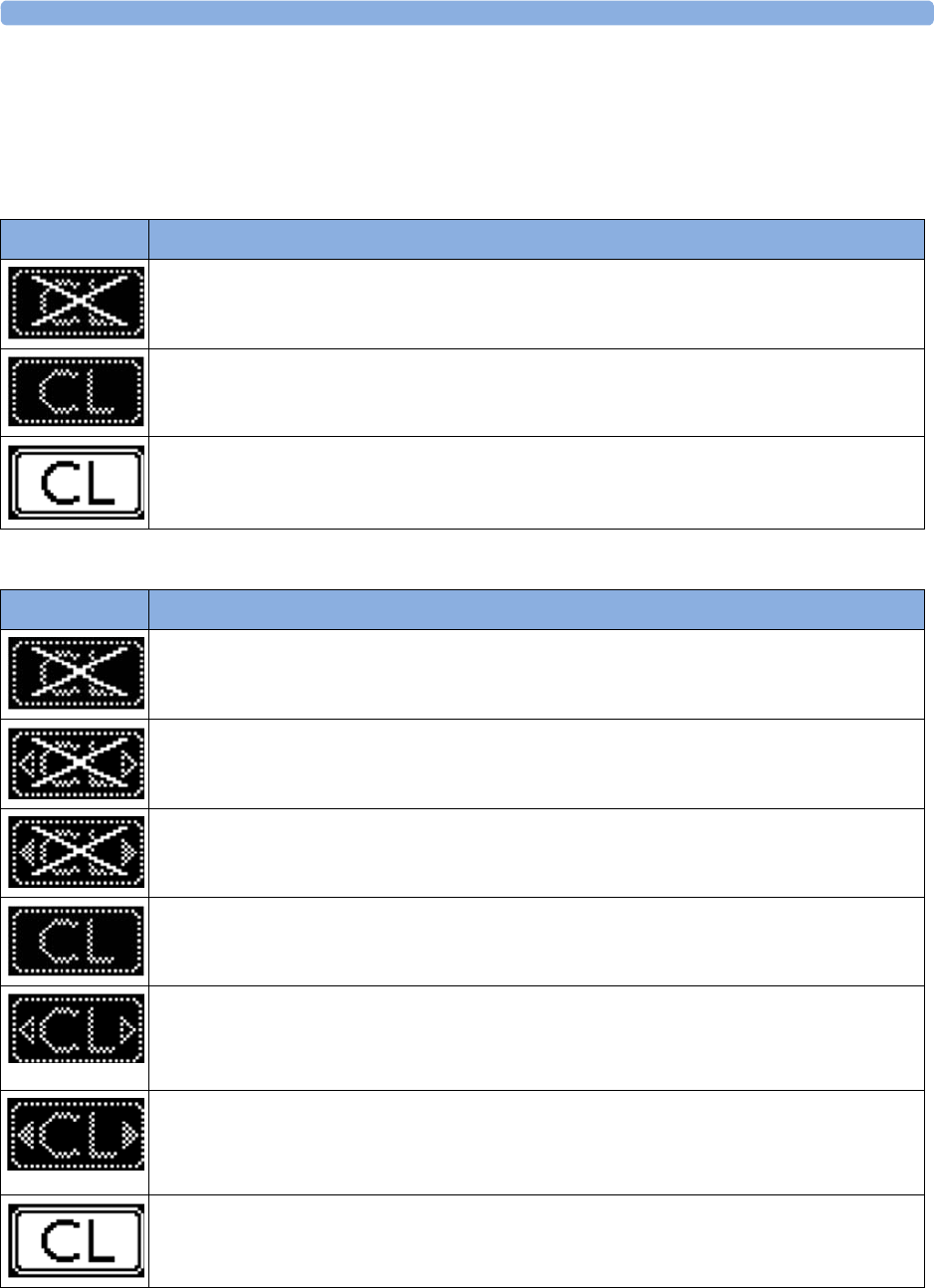
4 Cableless Monitoring
95
Cableless Status Indication
When the monitor recognizes a connected Avalon CL or Avalon CTS interface cable (red or black
connector), it confirms the recognition with the following status indicators displayed in the lower
right-hand corner of the screen:
Avalon CTS
Avalon CL
Indicator Description
Avalon CTS interface cable is connected to the monitor, but the Avalon CTS base station is not
connected to the interface cable, or it is disconnected from AC mains, or is in Standby mode.
Avalon CTS interface cable is connected to the monitor, Avalon CTS base station is connected,
powered on, and cableless transducers are ready to use, but no cableless transducers are currently
active (all are still docked at the base station).
Avalon CTS interface cable is connected to the monitor, Avalon CTS base station is connected,
powered on, and at least one cableless transducer is active and assigned.
Indicator Avalon CL
A base station is connected to the monitor, but the base station is in Standby mode.
A base station is connected to the monitor, but the base station is in Standby mode. The CL Wide
Range Pod is activated and trying to connect to the monitor.
A base station is connected to the monitor, but the base station is in Standby mode. The CL Wide
Range Pod is activated and connected to the monitor.
A base station is connected to the monitor but no cableless transducers and no cableless Pods are
currently active. All are still docked at the base station, or the base station holds no transducers.
A base station is connected to the monitor but no cableless transducers and no cableless Pods
(except the CL Wide Range Pod) are currently active. All are still docked at the base station, or the
base station holds no transducers. The CL Wide Range Pod is activated and trying to connect to
the monitor.
A base station is connected to the monitor but no cableless transducers and no cableless Pods
(except the CL Wide Range Pod) are currently active. All are still docked at the base station, or the
base station holds no transducers. The CL Wide Range Pod is activated and connected to the
monitor.
A base station is connected to the monitor, it is on, and minimum one assigned cableless
transducer or cableless Pod is active.
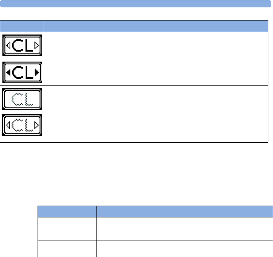
4 Cableless Monitoring
96
NOTE
A CL transducer is considered still active, even if it has an INOP condition (e.g.
cl US Disconnect
), until
it is either deactivated by docking it at the base station, or until it is manually removed from the
Tele
Info
window.
Pop-up Keys
Messages
The fetal monitor issues messages to certain user interactions. For example, if the CL SpO2 Pod is
picked up from the base station to activate it, the monitor displays the message
cl SpO Added
and the
equipment label of the CL Pod.
A base station is connected to the monitor, it is on, and minimum one assigned cableless
transducer or cableless Pod is active. The CL Wide Range Pod is activated and trying to connect
to the monitor.
A base station is connected to the monitor, it is on, and minimum one assigned cableless
transducer or cableless Pod is active. The CL Wide Range Pod is activated and connected to the
monitor.
A CL transducer has moved away from the base station and is approaching the limit of the area of
reach (min. 100 m/300 ft in line of sight). The US sound is replaced by an artificial QRS sound
(like DECG). The DECG and MECG waves are no longer displayed.
A CL transducer has moved away from the base station and is approaching the limit of the area of
reach (ca. min. 100 m/300 ft in line of sight). The US sound is replaced by an artificial QRS sound
(like DECG). The DECG and MECG waves are no longer displayed. The CL Wide Range Pod is
activated and trying to connect to the monitor.
Indicator Avalon CL
Pop-Up key Function
Remove
Selecting the
Remove
key deactivates and unassigns the selected active
transducer or CL Pod and removes it from the list. This key is disabled if no
active device is selected.
Find
Selecting the
Find
key pages the selected active CL transducer. This key is
disabled if no active device is selected.

4 Cableless Monitoring
97
Use Priority When Combining Cableless and Wired Measurements
CL Transducers versus wired transducers
CL transducers have priority over wired transducers. If an Avalon CL or Avalon CTS base station is
connected to the fetal monitor, and both wired and CL transducers are connected to the monitor, all
the wired transducers are disabled whenever one CL transducer is active. To switch back to using
wired transducers, switch the base station to Standby mode, or redock all CL transducers at the base
station, and continue monitoring with the wired transducers.
CL NBP and CL SpO2 versus fetal monitor built-in NBP and SpO2 measurements
CL NBP and CL SpO2 have priority over the built-in NBP and SpO2 measurements. If a CL NBP or
CL SpO2 Pod is activated, the corresponding built-in measurement of the fetal monitor is deactivated.
To switch back to the built-in measurements, switch the base station to Standby mode, or redock the
CL Pods at the base station.
CL F&M Pod versus wired transducers
The CL F&M Pod has priority over wired transducers. If a CL F&M Pod is active, all the wired
transducers are disabled. To switch back to using wired transducers, switch the base station to Standby
mode, or redock the CL F&M Pod at the base station.
About RF Signal Quality
If you cannot get sufficient ultrasound signal quality using the Avalon CTS base station, try
repositioning the transducers, or switch to wired transducers.
Using an Avalon CL base station you should get a better signal by reducing the distance between the
CL transducer and the base station.
Signal transmission can be disturbed if:
• the patient is out of range of the receiving area.
• there is interference from another, possibly stronger, RF signal (a broadcasting station, for
instance).
• the patient is near material that absorbs electromagnetic waves (for example, metal-reinforced
concrete, elevator doors) or the base station is in an enclosed metal rack.

4 Cableless Monitoring
98
CL Transducer Assignment
The CL transducers are assigned by simply docking them at the Avalon CL base station connected to
the patient’s fetal monitor.
Since twins and triplets can be monitored with the Avalon CL base station, it can be delivered with up
to six CL transducers: one CL Toco+ MP, three CL US, and two CL ECG/IUP transducers. Up to
four CL transducer can be assigned at one time to the Avalon CL base station. Four assigned
CL transducers enable monitoring combinations such as 1 CL Toco+ MP transducer + 3 CL US
transducers for monitoring triplets externally, or 1 CL Toco+ MP transducer + 2 CL US transducer +
1 CL ECG/IUP transducer for monitoring twins.
Three CL transducers can be docked and charged at the Avalon CL base station at a time. If a fourth
transducer should be assigned to the Avalon CL base station:
1Remove first the three docked CL transducers from the base station and place them on the patient.
2Then dock the remaining fourth transducer at the base station and wait until the LED of the
fourth transducer signals that it has communication with the base station.
3Place the fourth CL transducer on the patient and check on the fetal monitor in the
Tele Info
window if the base station and the monitor have communication with all four transducers, and if
their numerics are displayed on the screen of the fetal monitor.
CL Transducer Unassignment
The cableless transducer needs to be unassigned:
• before being used with another base station on another patient
• to allow cleaning before docking it back onto the base station (e.g. to replace it with a fully charged
transducer of the same type)
There are three methods to do this:
1Open the setup menu of the measurement e.g.
FHR1
by selecting the numeric on the screen.
2Select
Remove
from the open setup menu.
3A confirmation window opens with the prompt
Please Confirm
and
Device will be removed
.
4Select the
Confirm
pop-up key. A message confirms
cl US has been removed
.
or
1Open the
Tele Info
window.
2Select the symbol of the cableless transducer you want to unassign, and select
Remove
from the
pop-up menu.
3A confirmation window opens with the prompt
Please Confirm
and
Device will be removed
.
4Select
Confirm
the pop-up key. A message confirms
cl US has been removed
.
or
1Redock the CL transducer at the base station.
2Switch the base station to stand-by.
3Remove the CL transducer; it is now unassigned.

4 Cableless Monitoring
99
NOTE
When a CL transducer is unassigned, all the measurements from this transducer are no longer
monitored; e.g. if you unassign a CL Toco+MP transducer, the Toco measurement, maternal Pulse, or
possibly also MECG or DECG are no longer monitored.
CL Pod Assignment
The CL Pods are assigned by simply docking them at the Avalon CL base station connected to the
patient’s fetal monitor.
CL Pod Unassignment
The CL Pods have to be unassigned:
• before assigning them to another base station or to another patient
• to allow cleaning, before docking them back onto the base station
There are three methods to do this:
1Open the setup menu of the measurement e.g. by selecting the numeric on the screen.
2Select
Remove
from the open setup menu.
3A confirmation window opens with the prompt
Confirm
and
Device will be removed
.
4Select the
Confirm
pop-up key. A message confirms
<cl Measurement> has been removed
.
or
1Open the
Tele Info
window.
2Select the symbol of the CL Pod, and select
Remove
from the pop-up menu.
3A confirmation window opens with the prompt
Confirm
and
Device will be removed
.
4Select the
Confirm
pop-up key. A message confirms
<cl Measurement> has been removed
.
or
1Redock the CL Pod at the base station.
2Switch the base station to stand-by.
3Remove the CL Pod; it is now unassigned.
To unassign a IntelliVue CL Pod using its user interface, see the Cableless Measurement
Instructions for Use.
NOTE
If you unassign a CL Pod, all the measurements from it are no longer monitored, or are monitored by
a connected lesser prioritized sensor.

4 Cableless Monitoring
100
Preparing to Monitor Cablelessly
When monitoring cablelessly with the FM20/30/40/40 monitors, most of the same procedures apply
as described in “Preparing to Monitor” on page 48. Additions and deviations applying to cableless
devices and existing procedures are described here.
CL Transducers
1To monitor cablelessly with the CL transducers, assign them at the base station as described in
“CL Transducer Assignment” on page 98.
2Place the CL transducers and the belt on the patient described in “Fastening Belts and
Transducers” on page 50.
3Check the measurements on the monitor, and if necessary, move the CL transducers until you have
a good signal for all measurements.
IntelliVue CL Pods
1To monitor cablelessly with the IntelliVue CL Pods, assign them at the base station as described in
“CL Pod Assignment” on page 99.
2Put the CL Pods in their cradles and place them on the patient as described in the IntelliVue
Cableless Measurements Instructions for Use.
Applying the CL Fetal & Maternal Patch and Pod
WARNING
Do not use the CL Fetal & Maternal Pod and electrode patch for monitoring if:
• The skin on the abdomen of the patient has established erythema, lesions, infection, inflammation,
or any kind of injuries at the applications site
• The patient has a history of skin irritation, allergies, or hypersensitivity to adhesives
• The patient carries multiple fetuses
• The gestational age is less than 36 completed weeks. The measurement method is also only
validated with patients in labor.
CAUTION
During handling, avoid close contact of the CL Fetal & Maternal Pod or the electrode patch to an
implanted pacemaker or defibrillator.

4 Cableless Monitoring
101
At the Mother's Side
1Have a new single-use electrode patch ready, and make sure that the pouch is still intact. Check the
expiration date that is printed on the pouch.
2Clean the application area on the abdomen of the patient. Use mild soap to wash any cream, oil, or
gel from the abdomen. Make sure to thoroughly wipe the area dry afterwards, ideally using paper
towels.
3Take the electrode patch from its pouch.
4Study the electrode patch Instructions for Use showing the correct placement of the electrode
patch on the abdomen of the patient.
5Remove the cover from the adhesive area under the central area of the patch. (Do not remove the
cover from any of the five surrounding electrodes yet).
6Verify the correct orientation of the patch. The “Philips/Monica” printed top electrode must point
to the patient’s chest.
7Place the central adhesive area of the patch over the patient’s umbilicus as shown in the patch
Instructions for Use. Then press it down.
For patients with a displaced umbilicus:
Where the umbilicus has been displaced downwards, position the center of the patch along the
midline, where it intersects the horizontal line passing over the iliac crests. Alternatively, estimate
the mid-point between the fundus and symphysis pubis.
For very obese patients or patients with a large panniculus:
An alternative strategy is to position the patch along the midline such that the edge of the top
electrode is placed 10-12 cm (4-5 in) below the fundus.
8Lift up one of the four electrodes. Identify the small area of the skin where you will place the
center of the electrode.
9Use one piece of abrasive ECG skin preparation paper to prepare the patient's skin. Make three
horizontal and three vertical strokes with the skin preparation paper. Focus the strokes on the
small area of the skin where the conductive center of the electrode will be placed. Make deliberate
but gentle strokes, lifting the finger after each stroke.
CAUTION
Do not use too much pressure with the abrasive skin preparation paper to avoid skin injury.
10 Remove the protective cover from the electrode. Place the electrode on the prepared skin. Press it
down firmly, but avoid pressing the central gel area of electrode.
11 Repeat the steps for the skin preparation and electrode placement for the other three electrodes.
incorrect correct
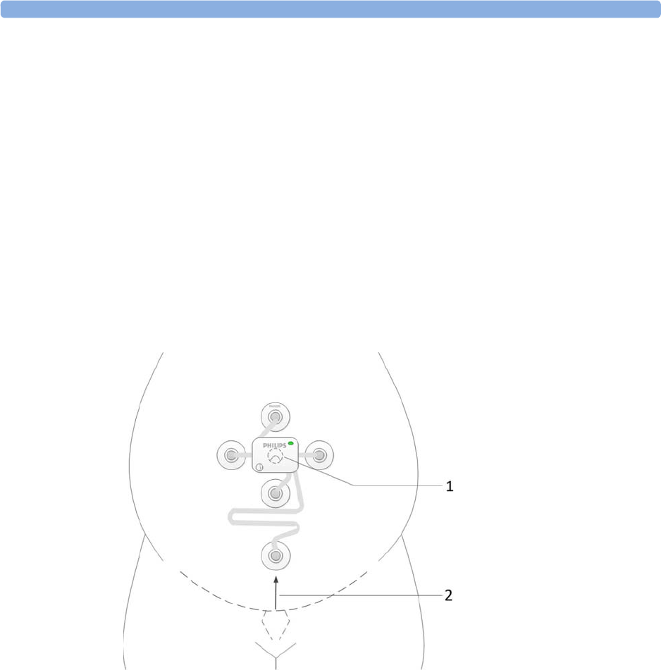
4 Cableless Monitoring
102
12 For the last remaining electrode attached to the long flexible cable, identify the small area of skin
to prepare, so that the center of this reference electrode will be positioned on the midline,
approximately 6 cm (2.4 in) above the rim of the symphysis pubis.
For patients with a displaced umbilicus, very obese patients, or patients with a large
panniculus:
Place the electrode on top of the panniculus approximating to the point 6 cm (2.4 in) vertically
from the symphysis pubis. If during monitoring the aFHR signal quality is poor, reposition the
electrode lower down on the abdomen to maximize the FHR signal, and consider placing the
electrode under the panniculus just below the turn.
13 Prepare the skin like for the first four electrodes.
14 Remove the protective cover from the electrode. Then place the electrode on the prepared skin
and press it down firmly, but avoid pressing the central gel area of electrode.
15 Assign a CL F&M Pod at the base station as described in “CL Pod Assignment” on page 99.
16 Place the CL F&M Pod on the electrode patch.
1CL F&M Pod and
electrode patch
centered on the
umbilicus
2Placement of electrode
6 cm (2.4 in) above the
rim of the symphysis
pubis
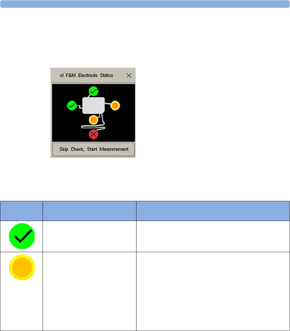
4 Cableless Monitoring
103
At the Monitor
After you have placed the CL F&M Pod on the electrode patch, the
cl F&M Electrode Status
window
opens at the monitor.
In the
cl F&M Electrode Status
window, the electrodes and their skin contact status are shown. The skin
contact status indicates, whether the skin preparation at each electrode site was successful.
1There are three methods to reopen a closed
cl F&M Electrode Status
window. Select:
–The
clF&M Status
SmartKey (configurable)
–
cl F&M Status
in the setup menu of one of the CL F&M parameters (for example,
Setup aFHR1
)
–
cl F&M Status
from the
Main Setup
menu
Electrode
Status
Description What to Do
The skin contact status is good. When a good skin contact status is indicated for all five
electrodes, the
cl F&M Electrode Status
window closes, and the
measurement starts automatically.
Further skin preparation may be
required.
1Carefully remove the electrode from the skin.
2Dry the skin.
3Repeat the skin preparation procedure.
4If the contact status cannot be improved, you can choose
to skip the electrode status check by selecting the
Skip
Check, Start Measurement
button in the
cl F&M Electrode
Status
window. Measurement accuracy should not be
affected, but fetal heart rate detection may be less
sensitive.

4 Cableless Monitoring
104
NOTE
If you have to repeat the skin preparation, or fix a loose electrode, ensure that enough wet gel remains
in the conductive middle of the electrode during the reapplication of the electrode. Add additional
fixation (any type of medical grade tape) to the pad in case the adhesive is compromised.
• If you cannot get a good measurement signal quality, use an alternative monitoring method.
• The electrode patch can remain applied for up to 48 hours. Remove the electrode patch, if there
are signs of skin irritation.
• If you have to replace an electrode patch:
– Gently remove the electrode patch from the abdomen of the patient.
– Wipe the abdomen dry thoroughly.
– Apply a new patch over exactly the same location. In this case, no further skin preparation is
required.
• Monitoring with the CL F&M Pod and electrode patch can continue when the patient takes a
shower. However, ensure that the CL F&M Pod remains on the electrode patch all the time, to
keep the contacts of the electrode patch dry. The achievable maximum wireless operating range
may be compromised when monitoring under a shower.
• The CL Fetal & Maternal Pod is not intended for underwater monitoring, for example in a
bathtub.
CAUTION
Do not reuse a patch on another patient due to the risk of cross contamination.
Further skin preparation is required. 1Carefully remove the electrode from the skin.
2Dry the skin.
3Repeat the skin preparation procedure.
4It is not recommended to skip the electrode status check,
if bad skin contact quality is persistently indicated for one
or more electrodes.
Electrode status is unknown. This status may be shown temporarily, or in case of a patch
malfunction, combined with an INOP message.
Electrode
Status
Description What to Do

4 Cableless Monitoring
105
After Monitoring
1After monitoring is done, remove the CL F&M Pod from the electrode patch.
2Clean and disinfect the CL F&M Pod, see “Care and Cleaning” on page 261.
3Dock the CL F&M Pod back at the base station.
4Gently remove the electrode patch and the electrodes from the abdomen of the patient.
5Dispose of the electrode patch.
6Remove the residuals of the adhesive from the patient's skin.
CL Wide Range Pod
The CL Wide Range Pod extends the signal range for the cableless measurement devices worn by the
ambulating patient.
1Assign the CL Wide Range Pod at the base station as described in “CL Pod Assignment” on
page 99.
2Activate the CL Wide Range Pod by taking it off the base station.
The CL Wide Range Pod connects itself over WLAN and LAN with the fetal monitor. As soon as
the connection to the monitor is established, the CL Wide Range Pod takes over from the base
station, and sends the signals from the cableless devices to the monitor. The connection status of
the CL Wide Range Pod is shown on the monitor, see “Cableless Status Indication” on page 95.
3Hand the CL Wide Range Pod to the patient to carry with her, or optionally wearing it using the
Mobile CL Transmitter Cradle (989803168881). The CL Wide Range Pod should be worn with its
rear side facing the body.
CL Wide Range Pod carried in hand, or CL Wide Range Pod worn with the belt clip (supporting
loop and belt clip part of the optional Mobile CL Transmitter Cradle).
4While the CL Wide Range Pod is active, cableless devices can still be assigned or unassigned at the
base station dynamically to the patient. To hand the signal transfer back from the CL Wide Range
Pod to the base station, redock the CL Wide Range Pod at the base station.

4 Cableless Monitoring
106
Battery Lifetime Management
The lifetime of a Lithium Ion battery depends on the frequency and duration of use.
CL Transducers
Battery replacement is recommended after 500 charge-discharge cycles, or if the battery is older than
4 years whatever is reached first. If the battery of a cableless transducer has aged and an exchange of
the battery is highly recommended, a prompt message is displayed at the fetal monitor for ca.
60 seconds. The prompt is repeated whenever the
Tele Info
window is opened until the battery is
replaced. The CL transducer battery allows for 10 hours of continuous operation.
Depending on the transducer type the following messages are displayed:
cl US battery has aged. Replacement strongly recommended
cl Toco battery has aged. Replacement strongly recommended
cl ECG/IUP batt has aged. Replacement strongly recommended
If you are getting this message, contact your service personnel so they can replace the CL transducer's
battery.
CL F&M Pod
Pod replacement is recommended after 500 charge-discharge cycles, or if the battery is older than
4 years whatever is reached first. If the battery of a CL F&M Pod has aged and an exchange of the Pod
is highly recommended, a prompt message is displayed at the fetal monitor for ca. 60 seconds. The
prompt is repeated whenever the
Tele Info
window is opened. The CL F&M battery allows for 16
hours of continuous operation.
The following message is displayed:
cl F&M battery has aged. Replacement strongly recommended
If you are getting this message, contact your service personnel so they can replace the CL F&M Pod.
CL Wide Range Pod
Battery replacement is recommended after 500 charge-discharge cycles, or if the battery is older than
4 years whatever is reached first. If the battery of a CL Wide Range Pod has aged and an exchange of
the battery is highly recommended, a prompt message is displayed at the fetal monitor for ca.
60 seconds. The prompt is repeated whenever the
Tele Info
window is opened until the battery is
replaced. The CL Wide Range Pod battery allows for 4 hours of continuous operation
The following message is displayed:
cl WRP battery has aged. Replacement strongly recommended
CL NBP and CL SpO2 Pods
For battery charge-discharge cycles specification of the IntelliVue CL Pods (NBP and SpO2), refer to
the Service Guide of the Cableless Measurements.
Charge Cycle
The age of a lithium ion battery begins at the date of manufacture. The lithium batteries are designed
for frequent recharging. A complete charging cycle is only reached and counted, when all recharging
periods equal a 100% charge.

4 Cableless Monitoring
107
The date of manufacture and number of charge-discharge cycles can be printed out in a battery report.
Patient Transport Within the Hospital
During transport, the patient wearing the CL transducers can be transferred from one fetal monitor to
another fetal monitor.
1To stop monitoring, discharge the patient at the fetal monitor. Do not switch the CL base station
to Standby.
Note: If you switch the CL base station to Standby after the discharge, the CL transducers only
hold the assignment to the CL base station for 1 minute.
2Disconnect the CL base station from the fetal monitor.
3The CL transducers hold the assignment to the CL base station for 30 minutes. Transport the
patient wearing the CL transducers with the disconnected CL base station to another fetal
monitor.
4Connect the CL base station to the other fetal monitor. The fetal monitors need to have the same
software revisions, and the correct time and date settings.
5Manually admit the patient to the fetal monitor, unless the patient is transferred to the new fetal
monitor with the OB TraceVue/IntelliSpace Perinatal system.
6Resume monitoring. Once the base station and the transducer are connected and assigned to the
new monitor, the previous monitor can be switched off or to Standby.

4 Cableless Monitoring
108
Underwater Monitoring
Only the battery-operated CL transducers of the Avalon CL and Avalon CTS systems can be used to
monitor under water. You can use them to monitor patients in a bathtub or shower. This does not
apply to the IntelliVue CL SpO2, CL NBP, and the CL Wide Range Pod, do not immerse the CL Pods
into water.
The CL F&M Pod can be worn within the shower, if the Pod is securely placed on the electrode patch,
so that the contacts cannot get wet. Radio transmission range of the CL F&M Pod may be reduced
under a shower.
Cableless transmission distances are shorter when monitoring under water. A metal bathtub is likely to
further reduce the operating range.
WARNING
Never immerse the base station in liquid. You must protect it against water sprays or splashes. Place
the base station where there is no chance of contact with water, or falling into water or other liquids.
CAUTION
Avoid the use of pulsating water jets in the bath or shower while monitoring, as these can be
misinterpreted as an incorrect (or totally artificial) heart rate.
Toco Baseline drift: When using transducers under warm water, the temperature increase causes a
significant baseline change due to internal pressure increase. The depth under water at which the Toco
transducer is used also has an effect on the Toco baseline, as the water pressure increases with depth.
After immersion, allow one to two minutes for the pressure to stabilize, then adjust the Toco baseline
(between contractions), and check it frequently.
When using the transducers underwater, the radio transmission range is reduced, and signal loss may
occur.
Water-proof belts like M1562B are recommended for the cableless transducers when monitoring in
water.
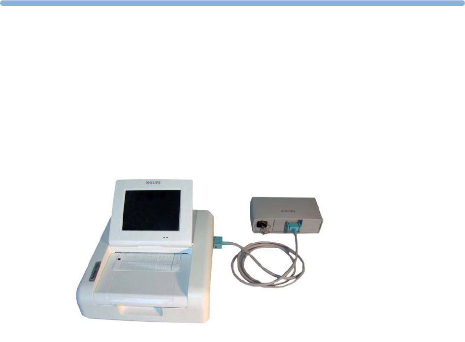
5
109
5FM20/30 Battery Option
You can switch between battery-powered and mains-powered (AC) operation without interrupting
monitoring.
The monitor is connected to the AC mains power via the external power supply.
NOTE
The battery option is not available for the FM40/FM50.
External Power Supply M8023A
The external power supply M8023A (option #E25) allows you to operate the fetal monitor from an
AC (alternating current) power source of 100 V to 240 V (±10%) and 50/60 Hz (±5%). If this option
is used, then the M8023A (option #E25) power supply is included for FM20/30.
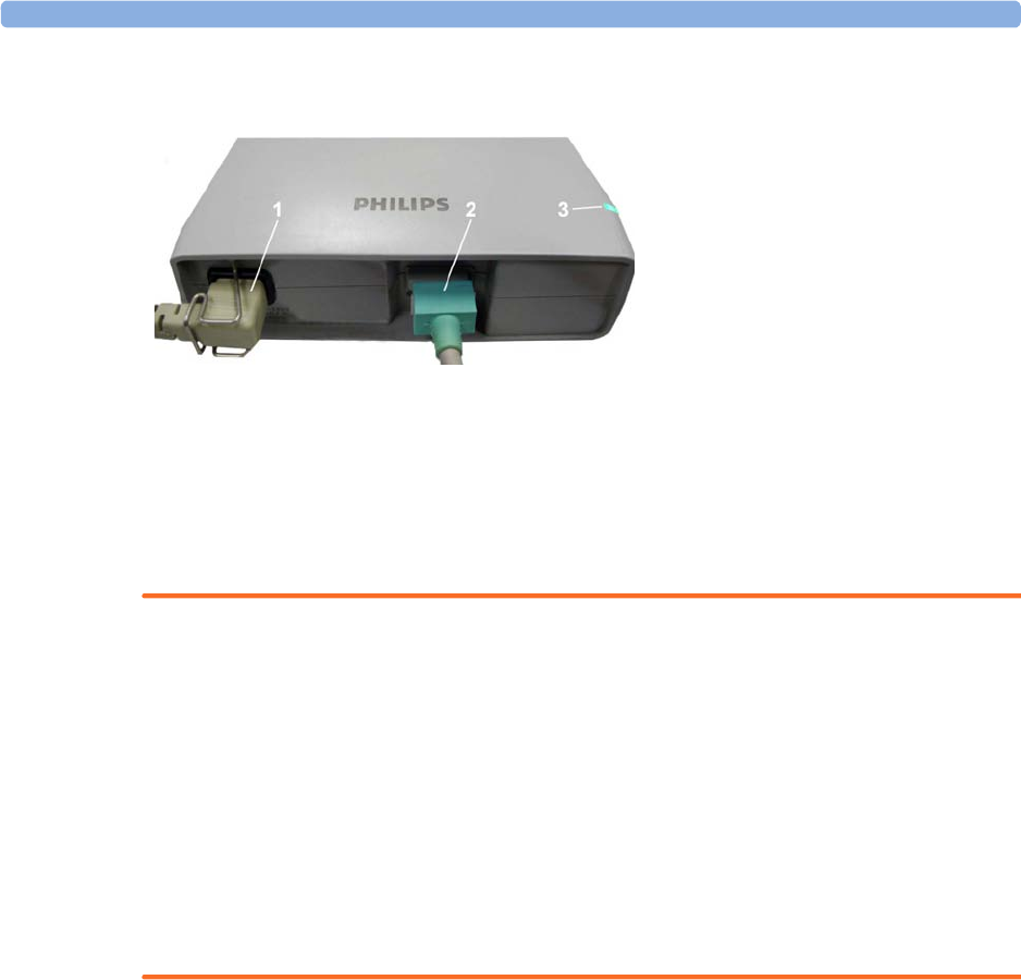
5 FM20/30 Battery Option
110
WARNING
• Always use the supplied power cord with the earthed mains plug to connect the external power
supply M8023A (option #E25) to an earthed AC mains socket. Never adapt the mains plug from
the power supply to fit an unearthed AC mains socket.
• Do not use AC mains extension cords or multiple portable socket-outlets. If a multiple portable
socket-outlet without an approved isolation transformer is used, the interruption of its protective
earthing may result in enclosure leakage currents equal to the sum of the individual earth leakage
currents, so exceeding allowable limits.
• Do not connect any devices that are not supported as part of a system.
• Any non-medical device placed and operated in the patient’s vicinity must be powered with an
approved isolation transformer that ensures mechanical fixing of the power cords and covering of
any unused power outlets.
Using Batteries
The Lithium Ion batteries used in your monitor store a large amount of energy in a small package. This
allows reliable battery-operated monitoring, but also requires care in use and handling of the batteries.
Follow the instructions in this chapter and see the Service Guide for further details.
Battery Power Indicators
The battery LED and battery status information on the main screen, in combination with INOP
messages and prompts, help you keep track of the battery power status. The indicators always show
the remaining capacity in relation to the battery's actual maximum capacity, which may lessen as the
battery ages. You can see the actual capacity in the
Battery Status
window.
1AC power cord, connected to AC mains socket
2Measurement Link (MSL) cable, supplies the power to the monitor for operation and for battery
charging
3Power-on LED, the green light is on when the external power supply is connected to the AC
mains
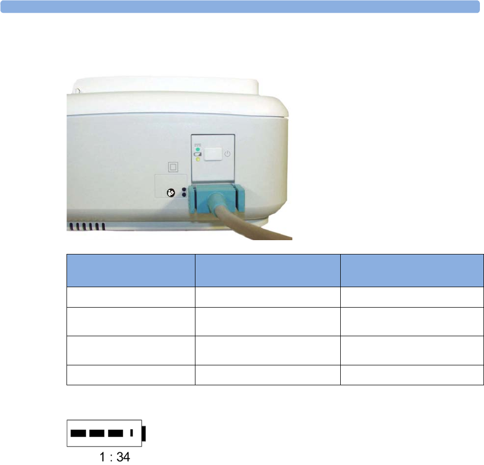
5 FM20/30 Battery Option
111
Battery LED
The possible battery LED status on the right side of the monitor is described in the table below.
Battery Status on the Main Screen
Battery status information is permanently displayed on all screens. It shows the status of the battery,
with the battery power remaining, with an estimate of the monitoring time this represents.
Battery power gauge: This shows the remaining battery power. It is divided into sections, each
representing 20% of the total power. If three sections are filled, as in this example, this indicates that
60% battery power remains. If no data is available from the battery, a question mark is shown in the
gauge.
Monitoring Time Available: Below the battery power gauge a time is displayed. This is the estimated
monitoring time available with the current battery power. Note that this time fluctuates depending on
the system load (the display brightness, the recorder configuration, and how many measurements you
carry out).
Battery LED Colors If the monitor is connected to
mains power, this means
If the monitor is running on
battery power, this means
Green Battery power is >90%
Yellow Battery charging (battery power
< 90%)
Red, flashing Less than 10 minutes power
remaining
Red, flashes intermittently Battery or charger malfunction Battery malfunction

5 FM20/30 Battery Option
112
Battery malfunction symbols: Normal battery function is indicated by the battery power gauge,
together with the remaining operating time, on the main screen. You are informed of problems or
changes in the status of the battery by the battery status/malfunction indicator. This consists of a blank
battery gauge containing a "!" symbol. If the symbol is red, this indicates a critical situation. You can
check the specific cause of the problem by looking at the symbol(s) displayed in the
Battery Status
window.
Battery Status Window
1To access the
Battery Status
window and its associated pop-up keys, select the battery status
information on the screen, or select
Main Setup
,
Battery
.
–
Capacity
,
remaining
tells you how much power is left in the battery.
–
Capacity
,
fullCharge
tells you how much power the battery can hold when fully charged.
–
TimeToEmpty
tells you approximately how long you can continue to use the monitor without
an AC connection. The time span fluctuates depending on the system load (the display
brightness and how many measurements you carry out), and the remaining capacity of the
battery.
–
TimeToFull
is shown in place of
TimeToEmpty
if the monitor is connected to a power supply,
and tells you how much time is left until the battery is charged to 90%. If >10 hr is shown
here, the battery may not charge completely when the monitor is in use.
Battery status/malfunction symbols: If a problem is detected with the battery, an INOP may be
issued, and the following symbols are displayed in the
Battery Status
window, where they may be
accompanied by a status message providing more details.
Battery Status Indicator Battery Malfunction Indicator
Alternates with the battery gauge
on the main screen.
Check in the
Battery Status
window to see which status
symbol is displayed to identify
the cause.
The red exclamation mark
flashes. Critical battery situation
or malfunction. Check in the
Battery Status
window to see
which malfunction indicator is
displayed, or refer to the INOP,
to identify the cause.
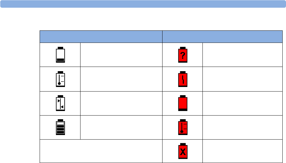
5 FM20/30 Battery Option
113
Symbols indicating critical situations are colored red.
Checking Battery Charge
To check the charge status of a battery, refer to the battery power gauge on the screen, or open the
Battery Status
window.
When Battery Lifetime is Expired
When the battery is aged, either after 3 years from manufacturing date or after 500 charge-discharge
cycles, it is recommended to replace the battery. To remind you of this, a message will appear in the
Battery Status
window. This message will only be displayed at the appropriate time when the date and
time on the monitor is correct.
Optimizing Battery Performance
The performance of rechargeable batteries may deteriorate over time. Battery maintenance as
recommended here can help to slow down this process.
Display Brightness Setting
1In the
Main Setup
menu, select
User Interface
,
Brightness
, then
Optimum
. This selects a level of
brightness suitable for most monitoring locations that uses less battery power than brighter
settings.
2Ensure that the current level of brightness is suitable for your monitoring location.
Battery Status Symbols Battery Malfunction Symbols
Battery is empty (Red) incompatible battery
Battery not charging as the
temperature is above or below
the specified range
(Red) battery malfunction
Battery requires maintenance (Red) battery has no power left
Charging stopped to protect the
battery
(Red) battery temperature too
high
(Red) battery is missing, insert
battery

5 FM20/30 Battery Option
114
Charging the Battery
To charge the battery:
1Connect the monitor to the external power supply (M8023A).
2Charge the battery until it is full, the battery LED is green, and the battery power gauge is filled.
During high load of the monitor (usage of multiple measurements) the battery may not charge. To
remedy this:
• reduce the load by removing measurements
• reduce the screen brightness or stop the recorder
Internal temperature conditions can also cause the battery to not charge. This is necessary to protect
the battery from damage and does not indicate a malfunction. Keep the monitor at room temperature
and move it away from heat sources or out of direct sunlight. The battery will resume charging when
the temperature is within range again. The battery will charge more quickly if the monitor is switched
off.
Conditioning the Battery
You must condition the battery when the "battery requires maintenance" symbol shows on the screen.
Do not interrupt the charge or discharge cycle during conditioning.
CAUTION
Condition the battery with a monitor not currently in use. The monitor switches off automatically
when there is no battery power left.
To condition the battery:
1Charge the battery until it is completely full. Open the
Battery Status
window and check that the
Batt fully charged
message is displayed.
2Disconnect the monitor from mains power, and let the monitor run until there is no battery power
left and the monitor switches itself off.
3Reconnect the monitor to mains power and charge the battery until it is full for use or charge to
50% for storage.

5 FM20/30 Battery Option
115
Battery Safety Information
WARNING
Use only Philips batteries part number M4605A. Use of a different battery may present a risk of fire
or explosion.
Do not open batteries, or dispose of them in fire, or cause them to short circuit. They may ignite,
explode, leak, or heat up, causing personal injury.
If battery leakage should occur, avoid contact with skin. Refer to qualified and authorized service
personnel.
Dispose of used batteries promptly and in an environmentally responsible manner. Do not dispose
of the battery in normal waste containers. Consult your hospital administrator to find out about local
arrangements. Do not expose batteries to liquids.
Do not crush, drop, or puncture batteries - mechanical abuse can lead to internal damage and internal
short circuits which may not be visible externally.
If a battery has been dropped or banged against a hard surface, whether damage is visible externally or
not:
• discontinue use
• dispose of the battery in accordance with the disposal instructions above.
Keep batteries out of the reach of children.
CAUTION
Do not disassemble, heat above 100°C (212°F) or incinerate the batteries, to avoid the risk of fire and
burns. Keep batteries out of the reach of children and in their original package until you are ready to
use them.
If battery leakage should occur, use caution in removing the battery. Avoid contact with skin. Refer to
qualified and authorized service personnel.
Do not install or use pre-damaged batteries.
Storing the Battery
WARNING
Remove the battery from the monitor when it is not used for a longer period of time, to avoid
potential damage caused by battery leakage.
Batteries should be charged to a maximum of 50% for storage.
The battery will discharge over time if it is stored inside the monitor without AC power connection.
The reported values for "remaining capacity" and "runtime" will become less accurate when the battery
is stored in this way for a longer period of time (that is, several weeks).

5 FM20/30 Battery Option
116
Cableless Monitoring with FM20/30 Battery Option
The CL Pods can be used with the FM20/30 with battery option #E25. The CL Pods can be assigned
and activated, but will not be charged. The only exception to this is the CL F&M Pod, which can also
be charged.
The charging time of the CL transducers can take up to 6 hours if they are charged from an FM20/30
with battery option.
If you charge the CL transducers at an FM20/30 with battery option, be sure to remove all wired
transducers from the fetal monitor. Leaving them connected to the fetal monitor can cause the
CL transducers not to charge at all.
Patient Transport Within the Hospital
The FM20 and FM30 fetal monitor with battery option offer the possibility of continuous monitoring
of a patient, while she is transported within the hospital.
1Unplug the MSL connector at the fetal monitor. Or, in case an external power supply is mounted
on a rollstand, unplug it from the AC Mains.
The fetal monitor is now operating on battery power.
2Move the patient with the fetal monitor (on a cart) to the new location.
3Reconnect the MSL connector at the fetal monitor or the external power supply to the AC Mains.

6
117
6Alarms
The alarm information here applies to all measurements. Measurement-specific alarm information is
contained in the sections on individual measurements.
The fetal monitor has two different types of alarm: patient alarms and INOPs.
Patient Alarms
Patient alarms are red and yellow alarms. A red alarm indicates high priority, such as a potentially life
threatening situation (for example, SpO2 below the desaturation alarm limit). A yellow alarm indicates
a lower priority alarm (for example, a fetal heart rate alarm limit violation).
INOPs
INOPs are technical alarms. They indicate that the monitor cannot measure and therefore not detect
critical conditions reliably. If an INOP interrupts monitoring and alarm detection (for example,
MECG
Leads Off
), the monitor places a question mark in place of the measurement numeric and sounds an
audible tone. INOPs without this tone indicate that there may be a problem with the reliability of the
data, but that monitoring is not interrupted.
INOPs are cyan by default. The following INOPs can also be configured as red or yellow INOPs to
provide a severity indication:
•
ECG Leads Off
•
Battery Empty
(FM20/30, CL devices)
•
Cuff Overpress
•
Cuff NotDeflated
•
No Pulse
Alarm Delays
There is a delay between a physiological event at the measurement site and the corresponding alarm
indication at the monitor. This delay has two components:
•The general measurement delay time is the time between the occurrence of the
physiological event and when this event is represented by the displayed numerical values.
This delay depends on the algorithmic processing and on the measurement dependent averaging
time.

6 Alarms
118
•The time between the displayed numerical values exceeding an alarm limit and the alarm
indication on the monitor. This delay is the sum of the alarm delay configured for the specific
measurement plus the system alarm delay. The system alarm delay is the processing time the
system needs for any alarm on the monitor to be indicated after the measurement has triggered the
alarm. See the performance specifications in “Specifications and Standards Compliance” on
page 287 for the system alarm delay specification.
Multiple Alarms
If more than one alarm is active, the alarm messages are shown in the alarm status area in succession.
An arrow symbol next to the alarm message informs you that more than one message is active.
The monitor sounds an audible indicator for the highest priority alarm. If more than one alarm
condition is active in the same measurement, the monitor announces the most severe alarm condition
first.
WARNING
Alarm systems of the monitor and those of the connected obstetrical information and surveillance
system are independent and not synchronized.
Alarming is only available at the Avalon fetal monitor, not at the Cableless Measurement Devices, see
the Instructions for Use for the IntelliVue Cableless Measurements.
If configured so,
SpO No Pulse
will only be displayed in yellow or red (instead of cyan), when no other
Pulse source is valid and is displayed instead of the Pulse from SpO2.
Alarm Mode
You can configure the alarm mode for your fetal monitor. There are two possible modes:
•
All
: alarms and INOPs are enabled, with all audible and visual indicators active.
•
INOP only
: only INOPs are enabled, with audible and visual indication active.
WARNING
In
INOP only
mode, no fetal/maternal patient alarms are enabled or indicated.
The alarm status area for yellow and red alarms shows the
INOP only
indication in conjunction with the
"Alarms Off" symbol. No individual measurement alarm limits or alarm off symbols are displayed. No
fetal/maternal patient alarm settings are available in the setup menus.
Nurse Call Systems
If configured to do so, red, yellow, and cyan alarms are indicated on a nurse call system which is
connected to the optional nurse call relay.

6 Alarms
119
Visual Alarm Indicators
Alarm message: An alarm message appears in the alarm status area on the second line at the top of
the screen indicating the source of the alarm. If more than one measurement is in an alarm condition,
the message changes every two seconds, and has an arrow at the side. The background color of the
alarm message matches the alarm priority: red for red alarms and red INOPs, yellow for yellow alarms
and yellow INOPs, and cyan for INOPs. The asterisk symbols (*) beside the alarm message match the
alarm priority: *** for red alarms, and ** for yellow alarms. INOPs are displayed without asterisks, but
a red INOP has !!! three exclamation marks, and a yellow INOP has !! two exclamation marks before it.
Depending on how your monitor is configured, it may display alarm limit violation messages:
• in text form, for example
** FHR1 Low
or
• in numeric form, for example
**FHR1 94<110
, where the second number shows the currently set
alarm limit, and the first number shows the value at which that alarm limit was violated by the
widest margin.
Flashing numeric: The numeric of the measurement in alarm flashes.
Bright alarm limits: If the alarm was triggered by an alarm limit violation, the corresponding alarm
limit on the monitor screen is shown more brightly.
Audible Alarm Indicators
The audible alarm indicators configured for your fetal monitor depend on which alarm standard
applies in your hospital. Audible alarm indicator patterns are repeated until you acknowledge the alarm
by switching it off or pausing it, or until the alarm condition ceases (if audible alarm indication is set to
non-latching).
WARNING
Do not rely exclusively on the audible alarm system for fetal monitoring. Adjustment of alarm volume
to a low level or off during monitoring may result in a dangerous situation. Remember that the most
reliable method of fetal monitoring combines close personal surveillance with correct operation of
monitoring equipment.
Alarm Tone Configuration
The audible alarm indicators of your monitor are configurable. In the monitor's Configuration Mode,
you can:
• increase the alarm volume of unacknowledged alarms at regular intervals
• change the interval between alarm sounds (ISO/IEC Standard alarms only)
• change the base volume of the red and yellow alarm tones and the INOP tones
• change the alarm sound to suit the different alarm standards valid in different countries
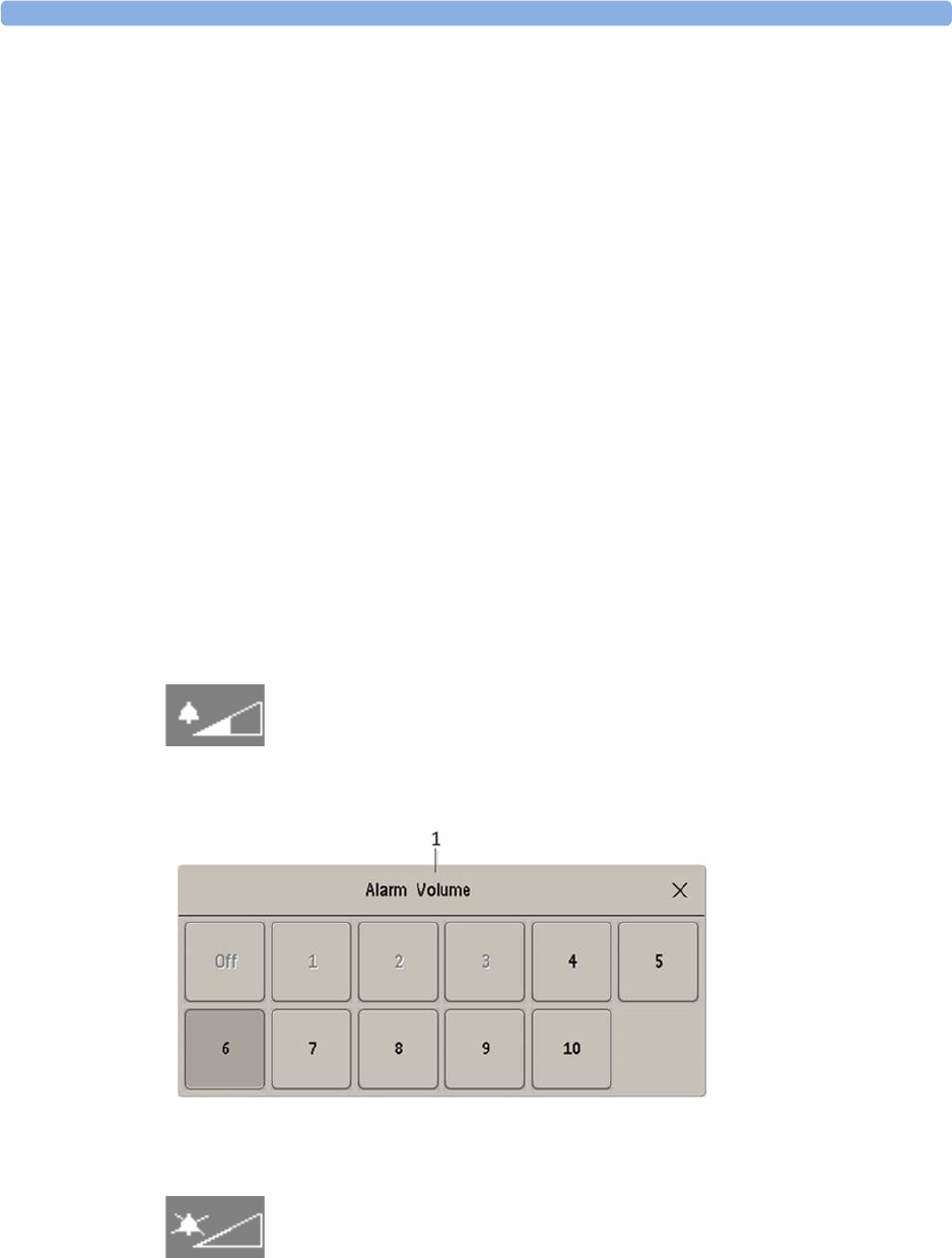
6 Alarms
120
Standard Philips Alarms
• Red alarms and red INOPs: a high pitched sound is repeated once a second.
• Two-star yellow alarms and yellow INOPs: a lower pitched sound is repeated every two seconds.
• One-star yellow alarms (short yellow alarms): the audible indicator is the same as for yellow
alarms, but of shorter duration.
• Standard INOPs: an INOP tone is repeated every two seconds.
ISO/IEC Standard Audible Alarms
• Red alarms and red INOPs: a high pitched tone is repeated five times, followed by a configurable
pause.
• Two-star yellow alarms and yellow INOPs: a lower pitched tone is repeated three times, followed
by a configurable pause.
• One-star yellow alarms (short yellow alarms): the audible indicator is the same as for yellow
alarms, but of shorter duration.
• Standard INOPs: a lower pitched tone is repeated twice, followed by a pause.
Changing the Alarm Tone Volume
The alarm volume symbol at the top right of the monitor screen gives you an indication of the current
volume. To change the volume:
1Select the volume symbol.
2The volume scale pops up.
3Select the required volume from the volume scale.
When the alarm volume is set to zero (
Off
), the alarm volume symbol shows this symbol:
If you switch the alarm volume off, you will not get any audible indication of alarm conditions.
1
Alarm Volume

6 Alarms
121
Minimum Volume for Severe Yellow or Red INOPs
Severe yellow or red INOPs require action to ensure the well-being of the patient. Therefore the
minimum volume for the INOP tone is set to at least alarm volume 8, irrespective of the current alarm
volume setting. The INOP tone will sound even if the monitor alarm volume is set to zero.
The severe INOPs for which this applies are:
Power Loss Tone
FM20/30 with
Battery
Option,
FM40/50
When power is lost - no power is available from the AC power source or from the battery - a beeper
will sound. The tone can be silenced by pressing the On/Standby button.
Acknowledging Alarms
To acknowledge all active alarms and INOPs, select the
Silence
key. This switches off the audible alarm
indicators.
• A checkmark beside the alarm message indicates that the alarm has been acknowledged.
• If the condition that triggered the alarm is still present after the alarm has been acknowledged, the
alarm message stays on the screen with a checkmark symbol beside it.
• If the alarm condition is no longer present, all alarm indicators stop and the alarm is reset.
• Switching off the alarms for the measurement in alarm, or switching off the measurement itself,
also stops alarm indication.
Acknowledging Disconnect INOPs
Acknowledging an INOP that results from a disconnected transducer, switches off the associated
measurement.
INOP Factory Default INOP tone
Battery Empty
cyan severe (fetal monitor with battery
option)
Battery Empty
cyan severe (CL transducers and Pods)
Cuff Overpress
cyan severe
Cuff NotDeflated
cyan severe

6 Alarms
122
Alarm Reminder
If
Alarm Reminder
is configured on for your monitor, you will get an audible reminder of alarm
conditions that remain active after you have acknowledged the alarm. This reminder may take the form
of a repetition of the alarm tone for a limited time, or an unlimited repetition of the alarm tone (this is
the same as a new alarm).
Alarm Reminder
is available only for yellow and red alarms and INOPs and
not for standard cyan INOPs.
In Configuration Mode, you can set the interval between silencing the alarm and sounding the
reminder tone to one, two, or three minutes.
Pausing or Switching Off Alarms
If you want to temporarily prevent alarms from sounding, for example while you are moving a patient,
you can pause alarms. Depending on your fetal monitor configuration, alarms are paused for one, two,
or three minutes, or infinitely.
To view the alarm pause setting chosen for your unit:
1Select
Main Setup
,
Alarms
,
Alarm Settings
.
2Check the
Alarms Off
setting.
This setting can be changed in Configuration Mode.
There are some settings made in Configuration Mode that can affect the availability of the pause
alarms functionality.
•The
Pause Alarms
/
Alarms Off
SmartKey can be removed from the screen to avoid unintentional
switching off of alarms. In this case you can only pause alarms or switch alarms off permanently in
the
Alarms
menu, under
Main Setup
.
•The
Pause Alarms
/
Alarms Off
SmartKey can be configured to pause or switch off red and yellow
alarms, yellow alarms only, or not to function at all. If it is configured not to function, you cannot
pause alarms or switch alarms off permanently at all.
When the alarms off priority is set to
Yellow Only
, the
Pause Alarms
/
Alarms Off
key becomes the
Pause
Yellow
/
Yellow Al. Off
.
To Pause All Alarms
If you have configured alarms to be paused for one, two, or three minutes, the SmartKey is labeled
Pause Alarms
.
Select the
Pause Alarms
SmartKey to pause all alarms.
Or
1Select
Main Setup
.
2Select
Alarms
.
3Select
Pause Alarms
.
6 Alarms
123
To Switch All Alarms Off
You can switch alarms off permanently if your monitor is configured to allow infinite alarms pause,
and the SmartKey is labeled
Alarms Off
.
Select the
Alarms Off
SmartKey.
Or
1Select
Main Setup
.
2Select
Alarms
.
3Select
Alarms Off
.
While Alarms are Paused or Off
When red alarms are paused or off:
In the alarm field, the monitor displays the message
Al. Paused x:yy
or
Alarms Off
, together with the
alarms paused symbol or the alarms off symbol.
When yellow alarms are paused or off:
In the alarm field, the monitor displays the message
YellowPaused x:yy
or
Yellow Alarms Off
, together
with the alarms paused symbol or the alarms off symbol.
For red and yellow alarms:
Alarms Paused
Alarms Off
• No alarms are sounded and no alarm messages are shown.
• INOP messages are shown but no INOP tones are sounded.
The only exceptions are the INOPs
Cuff NotDeflated
,
Cuff Overpress
, and
Battery Empty
from the
FM20/30 monitor with battery option.
These INOPs switch all alarms back on again, so that an INOP tone can be sounded. You must
remove the INOP condition first, before you can switch off or pause the alarms again.
Restarting Paused Alarms
To manually switch on alarm indication again after a pause, select the SmartKey
Pause Alarms
(or
Alarms Off
) again.
Alarm indication starts again automatically after the pause period expires. If the monitor is configured
to stay paused infinitely, you must select
Alarms Off
again to restart alarm indication.

6 Alarms
124
Extending the Alarm Pause Time
If your monitor has the function extended alarm pause enabled, you can extend the alarm pause time.
Use this to prevent alarms being indicated, for example, while you are washing a patient or carrying out
a procedure. Only extend the alarm pause time when you are sure that clinical personnel are available
to monitor the patient's condition closely.
To extend the alarm pause time to five or 10 minutes:
1Select one of the alarm fields. This calls up the
Alarm Messages
window.
2Select either the pop-up key
PauseAl. 5 min
or the pop-up key
PauseAl. 10 min
. Each time you
select one of these pop-up keys, the Alarm Pause Time is reset to five or 10 minutes.
To Switch Individual Measurement Alarms On or Off
This applies to alarm mode
All
.
1Select the measurement numeric to enter its setup menu.
2Select
Alarms
to switch between
On
and
Off
.
The alarms off symbol is shown beside the measurement numeric.
Alarm Limits
The alarm limits you set determine the conditions that trigger yellow and red limit alarms.
WARNING
Be aware that the monitors in your care area may each have different alarm settings, to suit different
scenarios. Always check that the alarm settings are appropriate before you start monitoring.
Viewing Individual Alarm Limits (Alarm Mode "All" Only)
You can usually see the alarm limits set for each measurement next to the measurement numeric on
the main screen.
1Alarm Limits
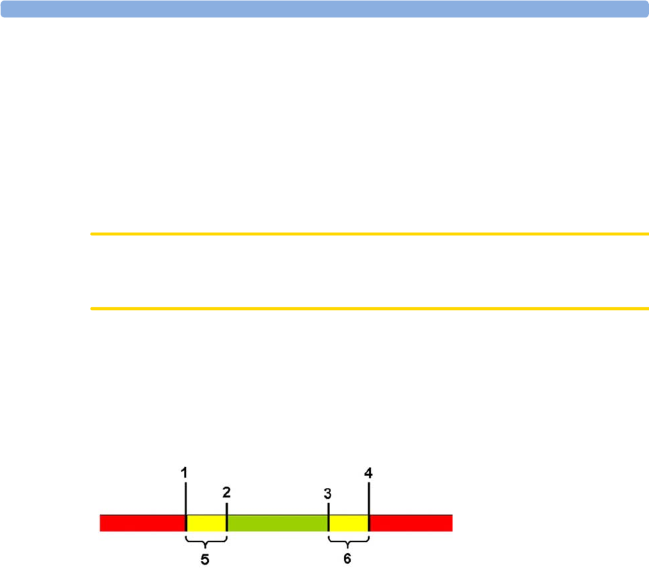
6 Alarms
125
If your monitor is not configured to show the alarm limits next to the numeric, you can see them in the
related measurement setup menu. Select the measurement numeric to enter the menu and check the
limits.
Changing Alarm Limits
To change individual measurement alarm limits using the measurement's setup menu:
1In the measurement's setup menu, select the alarm limit you want to change. This calls up a list of
available values for the alarm limit.
2Select a value from the list to adjust the alarm limit.
CAUTION
Set the alarm limits to a meaningful value for the individual patient. Setting the alarm limits to a too
high or too low value may render the alarm function useless.
Extreme Alarm Limits for Heart Rate and Maternal Pulse
The extreme rate alarms, Extreme Tachy and Extreme Brady, generated by the active alarm source,
either HR or Pulse, are set in Configuration Mode by adding a set value (the Δ value) to the high and
low alarm limits.
You need to know which value has been configured for your monitor. Changing the high and low
alarm limits automatically changes the extreme alarm limits within the allowed range.
To see the extreme rate alarms set for your monitor, in the
Setup ECG
menu, see the menu items
ExtrTachy
and
ExtrBrady
.
1Extreme Brady Limit
2Low Limit
3High Limit
4Extreme Tachy Limit
5Δ Extreme Brady
6Δ Extreme Tachy
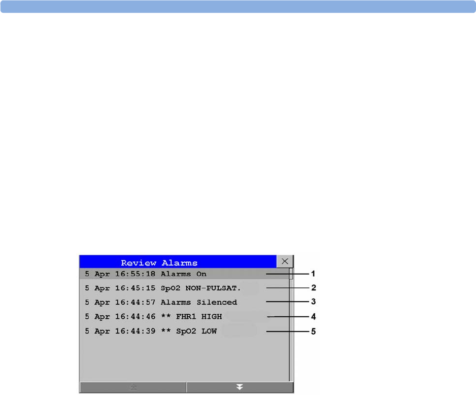
6 Alarms
126
Reviewing Alarms
To review the currently active alarms and INOPs, select any of the alarm status areas on the fetal
monitor screen. The
Alarm Messages
window pops up. All alarms and INOPs are erased from the
monitor's alarm history when you discharge a patient, or if you leave the Demonstration Mode.
Alarm Messages Window
The
Alarm Messages
window shows all the currently active alarms and INOPs in chronological order,
beginning at the top with the most recent. INOPs are shown on the left hand side, and alarms are
shown on the right hand side. Any active red alarms are shown first, followed by yellow alarms.
Acknowledged alarms or INOPs are shown with the checkmark symbol.
The
Alarm Messages
window pop-up keys appear when the window is opened. Selecting the
Review
Alarms
pop-up key opens the
Review Alarms
window.
Review Alarms Window
The
Review Alarms
window contains a list of up to 300 of the most recent alarms and INOPs with date
and time information. If configured to do so, each alarm is shown with the alarm limit active when the
alarm was triggered and the maximum value measured beyond this limit. The
Review Alarms
window
also shows any changes made to the
Alarms On/Off
or
Alarms Silenced
status. Only the main alarms
On/Off transitions are logged in the alarm history, and On/Off alarm transitions for individual
measurements are not logged.
The information in the
Review Alarms
window is deleted when a patient is discharged.
The
Review Alarms
window pop-up keys appear when the window is opened. Selecting the
Active
Alarms
pop-up key opens the
Alarm Messages
window.
Latching Alarms
The alarm latching setting for your monitor defines how the alarm indicators behave when you do not
acknowledge them. When alarms are set to non-latching, their indicators end when the alarm condition
ends. Switching alarm latching on means that visual and/or audible alarm indications are still displayed
or announced by the monitor after the alarm condition ends. The indication lasts until you
acknowledge the alarm.
1
Alarms On
2
SpO No Pulse
3
Alarms Silenced
4
** FHR1 High
5
** SpO Low

6 Alarms
127
Viewing the Alarm Latching Settings
To see the alarm latching setting for your monitor:
1In the monitor's
Main Setup
menu, select
Alarms
.
2Select
Alarm Settings
, and see the
Visual Latching
and
Audible Latching
settings.
This setting can be changed in Configuration Mode. You should be aware of the settings chosen for
your unit. There are three possible choices each for visual and audible latching:
Red & Yellow
,
Red Only
,
and
Off
. The audible latching configuration can never be configured to a higher level than that
configured for the visual latching. In other words, the audible latching setting is always the same level,
or lower, than the visual latching setting. For example, if visual latching is configured to
Red Only
, then
audible latching can only be set to
Red Only
or
Off
. The following table shows the possible
combinations for latching settings:
Alarm Latching Behavior
All INOPs except the "unplugged" INOPs are non-latching.
Possible Combinations for Alarm Latching Settings
Visual Latching Setting Audible Latching Setting
Red & Yellow Red & Yellow
Red & Yellow Red Only
Red & Yellow Off
Red Only Red Only
Red Only Off
Off Off
Alarm Condition Red and Yellow Measurement Alarms
Acknowledgment Presence Non-latching alarms Visual and audible
latching
Visual latching,
audible non-latching
Alarm has not been
acknowledged
Alarm
condition still
present
Alarm tone on
Alarm message
Flashing numerics
Alarm tone on
Alarm message
Flashing numerics
Alarm tone on
Alarm message
Flashing numerics
Alarm
condition no
longer present
All audible and visual
alarm indicators
automatically stop
Alarm tone on
Alarm message
Flashing numerics
Audible alarm
indicators automatically
stop
Alarm message
Flashing numerics
Alarm has been
acknowledged
Alarm
condition still
present
Alarm tone off
Audible alarm
reminder (if
configured)
Alarm message
Flashing numerics
Alarm tone off
Audible alarm reminder
(if configured)
Alarm message
Flashing numerics
Alarm tone off
Audible alarm reminder
(if configured)
Alarm message
Flashing numerics
Alarm
condition no
longer present
Audible and visual
alarm indicators
automatically stop
Audible and visual
alarm indicators
automatically stop
Audible and visual
alarm indicators
automatically stop

6 Alarms
128
Testing Alarms
When you switch the fetal monitor on, a self test is started. You should hear a single tone. This
indicates that the audible alarm indicators are functioning correctly. For further testing of individual
measurement alarms, perform the measurement on yourself (for example SpO2 or NBP) or use a
simulator. Adjust alarm limits and check that appropriate alarm behavior is observed.
To test the functioning of visible and audible alarms, do the following:
1Enable the alarm (Alarm Mode needs to be set to
All
, see the Configuration Guide).
2Set the alarm limits.
3Measure or simulate the parameter that is out of range, or signal loss.
4Verify that the visible and audible alarms are working.
As an example, to test the FHR alarms:
1Connect the US transducer to a fetal sensor socket.
2Enable the FHR alarming (see “Turning Alarms On or Off” on page 197).
Set the high alarm limit and delay to 150 bpm and 60 seconds respectively, and the low alarm limit and
delay to 110 bpm and 60 seconds respectively (see “Changing Alarm Limits” on page 197).
1Generate a fetal heart rate of approximately 180 bpm (3 beats per second) for more than one
minute.
2Verify the functioning of the visible and audible alarms.
Alarm Behavior at Power On
If the monitor is switched off for longer than one minute and then switched on again, or after a loss of
power lasting longer than one minute, the monitor can be configured to restore either the alarm
settings from the monitor's
User Defaults
, or the most recently used alarm settings. When a patient is
discharged, the
User Defaults
of the monitor are always restored independent of the setting. After any
of these situations, ensure that the alarm settings are appropriate for your patient. If power is lost for
less than one minute, the alarm settings prior to the power loss are restored.
•If
AlarmsOffAtStart
is enabled in Configuration Mode alarms will be initially paused or off the next
time the monitor is switched on, depending on a set of related configuration settings, see the
Configuration Guide.

7
129
7Patient Alarms and INOPs
This chapter lists alarms and technical alarms (INOPs) for the fetal monitors irrespective of their
priority.
Alarm Messages
Fetal alarms are identified by either "FHR", "dFHR", or aFHR. All other alarms without these
identifiers refer to maternal parameters. Alarm messages can be configured with the
Enhanced
setting
to give more information. These messages are shown additionally in the table below, with xxx for the
measured value and yyy for the alarm limit concerned.
Alarm Message From Condition Indication
** aFHR1 High
** aFHR2 High
** aFHR3 High
** aFHR1 xxx>yyy
** aFHR2 xxx>yyy
** aFHR3 xxx>yyy
FHR
(CL F&M Pod)
The fetal heart rate obtained from the
CL F&M Pod has risen above the high
alarm limit.
xxx denotes the highest measured value, and
yyy is the high alarm limit.
Numeric flashes and high
limit is highlighted, yellow
alarm message, alarm tone.
** aFHR1 Low
** aFHR2 Low
** aFHR3 Low
** aFHR1 xxx<yyy
** aFHR2 xxx<yyy
** aFHR3 xxx<yyy
FHR
(CL F&M Pod)
The fetal heart rate obtained from the
CL F&M Pod has fallen below the low
alarm limit.
xxx denotes the lowest measured value, and
yyy is the low alarm limit.
Numeric flashes and low limit
is highlighted, yellow alarm
message, alarm tone.
**aHR High
**HR xxx<yyy
HR
(CL F&M Pod)
The maternal heart rate obtained from the
CL F&M Pod has risen above the high
alarm limit.
xxx denotes the highest measured value, and
yyy is the high alarm limit.
Numeric flashes and high
limit is highlighted, yellow
alarm message, alarm tone.
**aHR Low
**HR xxx>yyy
HR
(CL F&M Pod)
The maternal heart rate obtained from the
CL F&M Pod fallen below the low alarm
limit.
xxx denotes the lowest measured value, and
yyy is the low alarm limit.
Numeric flashes and low limit
is highlighted, yellow alarm
message, alarm tone.

7 Patient Alarms and INOPs
130
*** Brady (Pulse)
***Brady/P xxx<yyy
SpO2The heart rate from the Pulse signal has
fallen below the bradycardia limit.
xxx denotes the lowest measured value; yyy
is the bradycardia limit.
Numeric flashes, red alarm
message, alarm tone.
*** Desat
*** Desat xx < yy
SpO2The SpO2 value has fallen below the
desaturation alarm limit. xx denotes the
lowest measured value, and yy is the
desaturation limit.
Numeric flashes, red alarm
message, alarm tone.
** dFHR1 High
** dFHR2 High
** dFHR3 High
**dFHR1 xxx>yyy
**dFHR2 xxx>yyy
**dFHR3 xxx>yyy
FHR (DECG) The fetal heart rate obtained from DECG
has risen above the high alarm limit.
xxx denotes the highest measured value, and
yyy is the high alarm limit.
Numeric flashes and high
limit is highlighted, yellow
alarm message, alarm tone.
** dFHR1 Low
** dFHR2 Low
** dFHR3 Low
**dFHR1 xxx<yyy
**dFHR2 xxx<yyy
**dFHR3 xxx<yyy
FHR (DECG) The fetal heart rate obtained from DECG
has fallen below the low alarm limit.
xxx denotes the lowest measured value, and
yyy is the low alarm limit.
Numeric flashes and low limit
is highlighted, yellow alarm
message, alarm tone.
*** Extreme Brady
***xBrady xxx<yyy
MECG The maternal heart rate obtained from the
maternal ECG has fallen below the extreme
bradycardia limit.
xxx denotes the lowest measured value, and
yyy is the extreme bradycardia limit.
Numeric flashes, red alarm
message, alarm tone.
*** Extreme Tachy
***xTachy xxx>yyy
MECG The maternal heart rate obtained from the
maternal ECG has risen above the extreme
tachycardia limit.
xxx denotes the highest measured value, and
yy is the extreme tachycardia limit.
Numeric flashes, red alarm
message, alarm tone.
** FHR1 High
** FHR2 High
** FHR3 High
**FHR1 xxx>yyy
**FHR2 xxx>yyy
**FHR3 xxx>yyy
FHR
(ultrasound)
The fetal heart rate obtained from
ultrasound has risen above the high alarm
limit.
xxx denotes the highest measured value, and
yyy is the high alarm limit.
Numeric flashes and high
limit is highlighted, yellow
alarm message, alarm tone.
** FHR1 Low
** FHR2 Low
** FHR3 Low
**FHR1 xxx<yyy
**FHR2 xxx<yyy
**FHR3 xxx<yyy
FHR
(ultrasound)
The fetal heart rate obtained from
ultrasound has fallen below the low alarm
limit.
xxx denotes the lowest measured value, and
yyy is the low alarm limit.
Numeric flashes and low limit
is highlighted, yellow alarm
message, alarm tone.
Alarm Message From Condition Indication

7 Patient Alarms and INOPs
131
** HR High
**HR xxx>yyy
MECG The maternal heart rate obtained from the
maternal ECG has risen above the high
alarm limit.
xxx denotes the highest measured value, and
yyy is the high alarm limit.
Numeric flashes and high
limit is highlighted, yellow
alarm message, alarm tone.
** HR Low
**HR xxx<yyy
MECG The maternal heart rate obtained from the
maternal ECG has fallen below the low
alarm limit.
xxx denotes the lowest measured value, and
yyy is the low alarm limit.
Numeric flashes and low limit
is highlighted, yellow alarm
message, alarm tone.
** <iTemp Label> High
iTemp The temperature value has exceeded the
high alarm limit.
Numeric flashes and high
limit is highlighted, alarm
tone.
** <iTemp Label> Low
iTemp The temperature value has dropped below
the alarm limit.
Numeric flashes and low limit
is highlighted, alarm tone.
** NBPs High
** NBPd High
** NBPm High
Noninvasive
blood pressure
The measured noninvasive blood pressure
value is above the high alarm limits
s
,
d
, or
m
after the label indicates whether the
systolic, diastolic, or mean pressure has
crossed the limit.
Numeric flashes and high
limit is highlighted, yellow
alarm message, alarm tone.
** NBPs Low
** NBPd Low
** NBPm Low
Noninvasive
blood pressure
The measured noninvasive blood pressure
value is below the low alarm limits
s
,
d
, or
m
after the label indicates whether the systolic,
diastolic, or mean pressure has crossed the
limit.
Numeric flashes and low limit
is highlighted, yellow alarm
message, alarm tone.
** Pulse High
SpO2The pulse rate has exceeded the high alarm
limit.
Numeric flashes and high
limit is highlighted, yellow
alarm message, alarm tone.
** Pulse Low
SpO2The pulse rate has dropped below the low
alarm limit.
Numeric flashes and low limit
is highlighted, yellow alarm
message, alarm tone.
** SpO High
SpO2The arterial oxygen saturation has exceeded
the high alarm limit.
Numeric flashes and high
limit is highlighted, yellow
alarm message, alarm tone.
** SpO Low
SpO2The arterial oxygen saturation has fallen
below the low alarm limit.
Numeric flashes and low limit
is highlighted, yellow alarm
message, alarm tone.
*** Tachy (Pulse)
***Tachy/P xxx>yyy
SpO2The heart rate from the Pulse signal has
exceeded the tachycardia limit.
xxx denotes the highest measured value, and
yyy is the tachycardia limit.
Numeric flashes, red alarm
message, alarm tone.
Alarm Message From Condition Indication

7 Patient Alarms and INOPs
132
Technical Alarm Messages (INOPs)
Monitor INOPs
INOP Message Indication What to do
2nd Tele Incompatible
Monitor: INOP tone One of the connected base stations is not supported by
the monitor. Check software revisions.
Bus Master Incomp
Monitor: INOP tone The Bus Master board or firmware is incompatible and
cannot be used with this monitor software revision.
Contact your service personnel.
Bus Master Malfunc
Monitor: INOP tone There is a problem with the monitor's hardware. Contact
your service personnel.
Check Flex Texts
Monitor: INOP tone If this INOP appears, check the monitor and patient
settings before you resume monitoring. If the settings are
unexpected, there may be a problem with the monitor
software. Contact your service personnel.
Check Keyboard
Monitor: INOP tone Perform a visual and functional check of the keyboard.
Contact your service personnel.
Check Monitor Func
Monitor: INOP tone A potential internal problem with the monitor has been
detected. Contact your service personnel.
Check Mouse
Monitor: INOP tone Perform a visual and functional check of the mouse input
device. Contact your service personnel.
Check OBR Config
Monitor: INOP tone OBR (OB Radio) channel configuration is invalid or
settings are not present. Check channel configuration and
hardware option.
Check Settings
Monitor: INOP tone If this INOP appears, check the monitor and patient
settings before you resume monitoring. If the settings are
unexpected, there may be a problem with the monitor
software. Contact your service personnel.
Check TI Config
Monitor: INOP tone If this INOP appears, the monitor can be used normally,
except for the Trace Interpretation feature. Contact your
service personnel.
Check Touch Input
Monitor: Display only Perform a visual and functional check of the touch input
device. Contact your service personnel.
Coincidence
!! Coincidence
Monitor: INOP tone The fetal heart rate(s) and maternal heart rate/pulse
persistently coincide with another. (see “Cross-Channel
Verification (CCV)” on page 159). The INOP tone has a
configurable delay. The default setting is an instant INOP
tone.
Internal.Comm.Malf
Monitor: INOP tone There is a problem with I2C Bus communication in the
monitor. Contact your service personnel.
NST Elapsed
Monitor: INOP tone
(Message and tone only if
Setup NST Timer
,
Notification
is set to
Alarm
in
Configuration Mode).
The time has expired for the NST timer. Clearing the
timer clears the INOP.

7 Patient Alarms and INOPs
133
FM20/FM30 Battery INOPs
OBR Interference
Monitor: INOP tone OBR (OB Radio) communication is disturbed by other
devices (not necessarily other wireless measurements).
Contact service personnel.
Paper End
Monitor: INOP tone The end of the paper pack is detected. Insert a new pack
of paper.
Settings Malfunct
Monitor: INOP tone The monitor cannot use the predefined settings for
monitoring. Contact your service personnel.
Speaker Malfunct
Monitor: INOP tone Contact your service personnel to check the speaker and
the connection to the speaker.
SRR Incompatible
Monitor: INOP tone The connected SRR (Short Range Radio) board or
firmware cannot be used with this base station's software
revision. Contact your service personnel.
SRR Interference
Monitor: INOP tone The short range radio connection has interference from
another device. Try using another channel.
SRR Invalid Chan
Monitor: INOP tone The channel configuration of the Short Range Radio is
invalid. Check channel and channel mask configuration.
SRR Malfunction
Monitor: INOP tone Malfunction in the SRR (Short Range Radio) module(s).
If the INOP persists, contact your service personnel.
Tele Incompatible
Monitor: INOP tone The base station is not supported by the monitor. Check
software revisions.
Tele Malfunction
Monitor: INOP tone Malfunction of the connected base station. If the INOP
persists contact your service personnel.
Tele Unplugged
Monitor: INOP tone The base station has been disconnected from the
monitor, while one or more CL devices were active. This
INOP is only issued, if the setting
Sensor Disconnct
is
No
Auto Off
, or the
Alarm Mode
is set to
All
.
Unsupported LAN
Monitor: INOP tone There is a problem with the communication to the
network and central monitoring is currently not possible.
Check the connection. If the INOP persists, switch off
the monitor and contact your service personnel.
User I/F Malfunct
Monitor: INOP tone Perform a visual and functional check of all the monitor
input devices. Contact your service personnel.
INOP Message Indication What to do
INOP Message Indication What to do
Batt Empty
Monitor: INOP tone
Battery LED at the monitor
flashes. During this INOP,
alarms cannot be paused or
switched off.
The estimated remaining battery-powered operating time
is less than 10 minutes. Connect the monitor to AC
immediately.
If the condition persists and the monitor is not connected
to mains power, this INOP is re-issued two minutes after
you acknowledge it.
Batt Incompat
Monitor: INOP tone The battery cannot be used with this monitor. Replace it
with the correct battery.

7 Patient Alarms and INOPs
134
Recorder INOPs
Batt Low
Monitor: INOP tone The estimated battery-powered operating time remaining
is less than 20 minutes.
Batt Malfunction
Monitor: INOP tone
Battery at the monitor
flashes. During this INOP,
alarms cannot be paused or
switched off unless the
monitor is connected to
mains power.
The monitor cannot determine the battery status. If the
INOP persists, replace the faulty battery. If the condition
persists and the monitor is not connected to mains power,
this INOP is reissued two minutes after you acknowledge
it.
Batt Missing
Monitor: INOP tone No battery found in FM20/30. Contact your service
personnel.
Charger Malfunct
Monitor: INOP tone
Battery at the monitor may
flash.
There is a problem with the battery charger in the
monitor. Connect the monitor to mains power and
contact your service personnel.
Check Batt Temp
Monitor: INOP tone The temperature of the battery is too high. Check that the
monitor is not exposed to heat.
INOP Message Indication What to do
INOP Message Indication What to do
Check Paper
Monitor: display only
Recorder: printout
Check that there is no paper jam, that the print drawer is
properly shut, that the paper is loaded with the grid facing
upwards, and that the correct Philips paper is being used.
FetRec Chk Config
Monitor: INOP tone
Recorder Speed
and/or
Scale Type
settings are set to
Unknown
and need to be set to the correct values in
Configuration Mode before the recorder can be operated.
FetRec Equip Malf
Monitor: INOP tone There is a problem with the fetal recorder hardware.
Contact your service personnel.
Printhead Overheat
Monitor: INOP tone The printhead is too hot. The recorder stops, the recorder
Start/ Stop
key is disabled, and remains so until the
printhead cools down sufficiently. Wait for the printhead
to cool down, then press the recorder
Start/ Stop
key or
the
Silence
key to clear the INOP.
Wrong Paper Scale
Monitor: INOP tone
Recorder: printout
The grid scale of the paper in the monitor does not match
the grid scale configured in the monitor. Make sure that
you use the correct paper and scale for your institution:
pre-printed: 30-240 in US and Canada, 50-210 in other
geographies.

7 Patient Alarms and INOPs
135
Wired Transducer INOPs
FHR (Ultrasound)
IUP
Toco
INOP Message Indication What to do
FHR1 Equip Malf
FHR2 Equip Malf
FHR3 Equip Malf
Monitor: INOP tone There is a problem with the FHR hardware. Contact your
service personnel.
FHR1 Signal Loss
FHR2 Signal Loss
FHR3 Signal Loss
Monitor: INOP tone
INOP tone if Alarm Mode is
set to
All
. No tone if Alarm
Mode is set to
INOP only
.
The input signal quality is not sufficient to process the
measurement. Adjust the position of the transducer to
obtain a better signal.
FHR1 Unplugged
FHR2 Unplugged
FHR3 Unplugged
Monitor: INOP tone Reconnect the FHR transducer to the monitor. Check if
all connections are sound.
INOP Message Indication What to do
IUP Equip Malf
Monitor: INOP tone There is a problem with the IUP hardware. Contact your
service personnel.
IUP Unplugged
Monitor: INOP tone Reconnect the IUP transducer to the monitor. Check if all
connections are sound.
INOP Message Indication What to do
Pulse(Toco) Malf
Monitor: INOP tone
Toco MP Maternal Pulse
Measurement
There is a problem with the Toco MP transducer
hardware. Contact your service personnel.
Toco Equip Malf
Monitor: INOP tone There is a problem with the Toco hardware. Contact your
service personnel.
Toco Unplugged
Monitor: INOP tone Reconnect the Toco transducer to the monitor. Check if
all connections are sound.

7 Patient Alarms and INOPs
136
Cableless Transducer INOPs
INOP Message Indication What to do
cl US Batt Empty
!!cl US Batt Empty
!!!cl US BattEmpty
cl Toco Batt Empty
!!clToco BattEmpty
!!!clTocoBattEmpty
cl ECG/IUP Empty
!!cl ECG/IUP Empty
!!!clECG/IUP Empty
Monitor: INOP tone
(configurable cyan, yellow,
red)
CL transducer: yellow tone
and LED flashes red
The remaining monitoring time with this transducer is
below 15 minutes. Charge battery.
cl US Batt Low
cl Toco Batt Low
cl ECG/IUP BattLow
Monitor: Display only
CL transducer: LED flashes
red
The remaining monitoring time with this transducer is
below 30 minutes. Charge battery.
cl US Batt Malf
cl Toco Batt Malf
clECG/IUP BattMalf
Monitor: INOP tone
CL transducer: tone and cyan
LED
Malfunction of the battery system (charger circuit or
battery) detected (e.g. persistent communication error,
overvoltage, overcurrent, battery incompatible). Contact
your service personnel.
cl US Check Temp
cl Toco Chk Temp
clECG/IUP Chk Temp
Monitor: INOP tone
CL transducer: tone and cyan
LED
The temperature of the transducer or its battery is
critically high. If the transducer is docked on the base
station, charging is interrupted. Check that the transducer
is not covered and do not expose it to a heat source. Do
not place the base station in a sunny window in a room
without active air conditioning. The environment
temperature to charge a transducer battery should not
exceed 40°C/104°F. If the INOP persists, remove the
transducer from patient and contact your service
personnel.
cl US Disconnect
cl Toco Disconnect
cl ECG/IUP Disconn
Monitor: INOP tone
CL transducer: tone and cyan
LED
The cableless transducer has lost the connection to the
monitor.
cl US Malfunction
cl Toco Malf
cl ECG/IUP Malf
Monitor: INOP tone
Numeric is replaced by a -?-
CL transducer: tone and cyan
LED
Malfunction of the transducer. Contact your service
personnel.

7 Patient Alarms and INOPs
137
CL Fetal & Maternal Pod INOPs
INOP Message Indication What to do
aFHR1 Signal Loss
aFHR2 Signal Loss
aFHR3 Signal Loss
Monitor: INOP tone
Numeric is replaced by a -?-
INOP tone if Alarm Mode is
set to
All
. No tone if Alarm
Mode is set to
INOP only
.
The input signal quality is not sufficient to process the
measurement. Reapply the electrodes of the electrode
patch.
cl F&M Batt Empty
!!cl F&M BattEmpty
!!!cl F&M BatEmpty
Monitor: INOP tone
(configurable cyan, yellow,
red)
CL F&M Pod: LED flashes
red and yellow tone
The remaining monitoring time with the CL F&M Pod is
below 15 minutes. Charge the battery.
cl F&M Batt Incmp
Monitor: INOP tone
CL F&M Pod: cyan LED and
INOP tone
The battery cannot be used with the CL F&M Pod.
Contact your service personnel.
cl F&M Batt Low
Monitor: Display only
CL F&M Pod: LED flashes
red
The remaining monitoring time with the CL F&M Pod is
below 30 minutes. Charge the battery.
cl F&M Batt Malf
Monitor: INOP tone
CL F&M Pod: cyan LED
Malfunction of the battery system (charger circuit or
battery) detected (for example: persistent communication
error, overvoltage, overcurrent, battery incompatible).
Contact your service personnel.
cl F&M Batt Temp
Monitor: INOP tone
CL F&M Pod: cyan LED
The temperature of the CL F&M Pod or its battery is
critically high. If the Pod is docked on the base station,
charging is interrupted.
Check that device is not covered. Do not expose device
to heat sources. If INOP persists, remove the CL F&M
Pod from patient. Contact your service personnel.
cl F&M Check Batt
Monitor: INOP tone
CL F&M Pod: cyan LED
During charging, the battery's temperature is below 0°C
(32°F), or above 45°C (113°F).
During discharge, the battery's temperature is below -5°C
(23°F), or above 55°C (131°F).
cl F&M Chk Chrg IF
Monitor: INOP tone
CL F&M Pod: cyan LED
There is an over-, or undervoltage at the charger interface.
Contact your service personnel.

7 Patient Alarms and INOPs
138
cl F&M Chk Electr.
Monitor: INOP tone
without tone, if no CL F&M
Pod parameter shows -?-
CL F&M Pod: cyan LED
• Not all electrodes have sufficient skin contact:
Prepare the skin at the application site further with
the abrasive pad.
• One or more leads between the measurement Pod
and the electrode(s) is broken: Replace the electrode
patch.
• Contact problem between the CL F&M Pod and the
electrode patch: Reconnect the CL F&M Pod.
This INOP can only occur in monitoring mode after the
initial electrode impedance check has occurred.
cl F&M ChkSettings
Monitor: INOP tone
CL F&M Pod: cyan LED
The CL F&M Pod settings are incompatible or corrupted.
Check the settings. Contact your service personnel.
cl F&M Disconnect
Monitor: INOP tone
CL F&M Pod: cyan LED
The CL F&M Pod has lost the connection to the monitor.
Call the patient back to the monitor. If the CL F&M Pod
has still no connection, remove it from the monitor, and
reassign it. If it still does not have a connection, contact
your service personnel.
cl F&M License Req
Monitor: INOP tone
CL F&M Pod: cyan LED
There is no valid license registered. Contact your service
personnel.
cl F&M Malfunction
Monitor: INOP tone
CL F&M Pod: cyan LED
The CL F&M Pod malfunctions. Contact your service
personnel.
cl F&M Patch Disc
Monitor: INOP tone
CL F&M Pod: cyan LED
The CL F&M Pod has been disconnected from the
electrode patch during monitoring mode. Reconnect the
CL F&M Pod.
cl F&M Patch Malf
Monitor: INOP tone
CL F&M Pod: cyan LED and
INOP tone
The connected electrode patch cannot be identified.
Either the electrode patch is malfunctioning, or the
connection between the CL F&M Pod and the patch is
defective.
cl F&M Remove
Monitor: INOP tone
CL F&M Pod: cyan LED and
INOP tone
The battery temperature is too high 60°C (140°F).
Remove the CL F&M Pod immediately from the patient.
Contact your service personnel.
INOP Message Indication What to do

7 Patient Alarms and INOPs
139
CL Wide Range Pod INOPs
INOP Message Indication What to do
cl WRP Batt Empty
!!cl WRP BattEmpty
!!!cl WRP BatEmpty
Monitor: INOP tone
(configurable cyan, yellow,
red)
CL Wide Range Pod: Display
only, yellow tone
The remaining time with the CL Wide Range Pod is
below 15 minutes. Charge the battery.
cl WRP Batt Incmp
Monitor: INOP tone
CL Wide Range Pod: Display
and INOP tone
The battery cannot be used with the CL Wide Range Pod.
Contact your service personnel.
cl WRP Batt Low
Monitor: Display only
CL Wide Range Pod: Display
only
The remaining monitoring time with the CL Wide Range
Pod is below 30 minutes. Charge the battery.
cl WRP Batt Malf
Monitor: INOP tone
CL Wide Range Pod: Display
only
Malfunction of the battery system (charger circuit or
battery) detected (for example: persistent communication
error, overvoltage, overcurrent, battery incompatible).
Contact your service personnel.
cl WRP Batt Temp
Monitor: INOP tone
CL Wide Range Pod: Display
only
The temperature of the CL Wide Range Pod or its battery
is critically high. If the Pod is docked on the base station,
charging is interrupted.
Check that device is not covered. Do not expose device
to heat sources. If INOP persists, remove the CL Wide
Range Pod from patient. Contact your service personnel.
cl WRP Chk Chrg IF
Monitor: INOP tone
CL Wide Range Pod: Display
and INOP tone
There is an over-, or undervoltage at the charger interface.
Contact your service personnel.
cl WRP ChkSettings
Monitor: INOP tone
CL Wide Range Pod: Display
and INOP tone
The CL Wide Range Pod settings are incompatible or
corrupted. Check the settings. Contact your service
personnel.
cl WRP Disconnect
Monitor: INOP tone
CL Wide Range Pod: Display
and INOP tone
The CL Wide Range Pod has lost the WLAN/LAN
connection for more than 10 seconds to the monitor.
cl WRP License Req
Monitor: INOP tone
CL Wide Range Pod: Display
and INOP tone
There is no valid license registered. Contact your service
personnel.
cl WRP Malfunction
Monitor: INOP tone
CL Wide Range Pod: Display
and INOP tone
The CL Wide Range Pod is malfunctioning. Contact your
service personnel.
cl WRP Remove
Monitor: INOP tone
CL Wide Range Pod: Display
and INOP tone
The battery temperature is too high 60°C (140°F).
Remove the CL Wide Range Pod immediately from the
patient. Contact your service personnel.

7 Patient Alarms and INOPs
140
DECG and MECG INOPs
INOP Message Indication What to do
dFHR1 Equip Malf
dFHR2 Equip Malf
dFHR3 Equip Malf
Monitor: INOP tone There is a problem with the DECG hardware. Contact
your service personnel.
dFHR1 Leads Off
!! dFHR1 Leads Off
!!!dFHR1 Leads Off
dFHR2 Leads Off
!! dFHR2 Leads Off
!!!dFHR2 Leads Off
dFHR3 Leads Off
!! dFHR3 Leads Off
!!!dFHR3 Leads Off
Monitor: INOP tone
Numeric is replaced by a -?-
One or more DECG lead is not attached. Make sure that
all required leads are attached, and no electrodes have
been displaced. Check all connections are sound, and that
the leg plate attachment electrode is properly attached. If
the INOP persists, try using another adapter cable, or leg
plate attachment electrode. If the INOP persists, contact
your service personnel.
dFHR1 Signal Loss
dFHR2 Signal Loss
dFHR3 Signal Loss
Monitor: INOP tone
Numeric is replaced by a -?-
INOP tone if Alarm Mode is
set to
All
. No tone if Alarm
Mode is set to
INOP only
.
The input signal quality is not sufficient to process the
measurement. Reapply the fetal scalp electrode.
dFHR1 Unplugged
dFHR2 Unplugged
dFHR3 Unplugged
Monitor: INOP tone
Numeric is replaced by a -?-
Reconnect the DECG transducer to the monitor. Check
if all connections are sound.
MECG Equip Malf
Monitor: INOP tone There is a problem with the MECG hardware. Contact
your service personnel.
MECG Leads Off
!! MECG Leads Off
!!! MECG Leads Off
Monitor: INOP tone
Numeric is replaced by a -?-
One or more MECG lead is not attached. Ensure that all
required leads are attached, and no electrodes have been
displaced. Check if all connections are sound. If the
INOP persists, try using another adapter cable. If the
INOP still persists, contact your service personnel.
MECG Unplugged
Monitor: INOP tone
Numeric is replaced by a -?-
Reconnect the MECG transducer to the monitor. Check
if all connections are sound.

7 Patient Alarms and INOPs
141
NBP INOPs
INOP Message Indication What to do
Cuff Not Deflated
!! Cuff Not Deflat
!!!Cuff Not Deflat
Monitor: INOP tone (severe
yellow/red INOP tone)
Numeric is replaced by a -?-
During this INOP, alarms
cannot be paused or switched
off.
Remove the cuff from the patient. Make sure that the
tubing is not kinked or twisted. Try restarting the
measurement. You can silence the INOP, but the INOP
message remains visible until the next measurement is
started, or the
Stop All
SmartKey is selected.
NBP Check Cuff
Monitor: INOP tone
Numeric is replaced by a -?-
Check if cuff is connected to the NBP Pod and cuff is
applied to the patient; check tubing and cuff for leakage.
Try restarting the measurement. If the INOP occurs
repeatedly, contact your service personnel. You can
silence this INOP, but the INOP message remains visible
until the next measurement is started or the
Stop All
SmartKey is selected.
This INOP is issued, when the maximum time for
inflation is exceeded, or when there is a significant change
in inflation time between two successive measurements in
auto and sequence mode.
NBP Cuff Overpress
!! Cuff Overpress
!!!Cuff Overpress
Monitor: INOP tone (severe
yellow/red INOP tone)
Numeric is replaced by a -?-
During this INOP, alarms
cannot be paused or switched
off.
The cuff pressure exceeds the overpressure safety limits.
Remove the cuff from the patient. Ensure that the tubing
is not kinked or twisted, and that the correct patient
category is selected.
Try restarting the measurement. You can silence this
INOP, but the INOP message remains visible until the
next measurement is started, or the
Stop All
SmartKey is
selected.
NBP Equip Malf
Monitor: INOP tone
Numeric is replaced by a -?-
Remove the cuff from the patient. The noninvasive blood
pressure hardware is faulty. Contact your service
personnel.
You can silence this INOP, but the INOP message
remains visible until the next measurement is started, or
the
Stop All
SmartKey is selected.

7 Patient Alarms and INOPs
142
CL NBP Pod INOPs
NBP Interrupted
Monitor: INOP tone
Numeric is replaced by a -?-
Check the tubing and cuff for leakages or kinks. Check
that you are using the correct cuff size and placement,
and that the correct patient category is selected. Try
restarting the measurement. If the INOP occurs
repeatedly, contact your service personnel.
You can silence this INOP, but the INOP message
remains visible until the next measurement is started, or
the
Stop All
SmartKey is selected. This INOP arises when
the measurement needed longer than the maximum time
allowed for inflation, deflation, or the total measurement.
NBP Measure Failed
Monitor: INOP tone
Numeric is replaced by a -?-
Check that you are using the correct cuff size and
placement, and that the correct patient category is
selected. Try restarting the measurement.
You can silence this INOP, but the INOP message
remains visible until the next measurement is started, or
the
Stop All
SmartKey is selected.
Check the condition and suitability of the patient for
noninvasive blood pressure monitoring. Use another cuff
to continue measuring.
INOP Message Indication What to do
INOP Message Indication What to do
Check Charger I/F
Monitor: INOP tone
CL NBP Pod: display
message
Overvoltage or undervoltage detected at the charger
interface. Clean contacts of charger interface at Cableless
Measurement Device and charging station. If the INOP
persists, contact your service personnel.
cl NBP Batt Empty
!!cl NBP BattEmpty
!!!cl NBP BatEmpty
Monitor: INOP tone
(configurable cyan, yellow,
red)
CL NBP Pod: display
message, yellow tone
The remaining battery time of the CL NBP Pod is below
30 minutes. Charge the battery.
cl NBP Batt Incomp
Monitor: INOP tone
CL NBP Pod: display
message
The battery in use with the CL NBP Pod is incompatible.
Replace it with one approved for use with the CL NBP
Pod.
cl NBP Batt Low
Monitor: INOP tone
CL NBP Pod: display
message
The remaining battery time of the CL NBP Pod is below
2 hours.
cl NBP Batt Malf
Monitor: INOP tone
CL NBP Pod: display
message
There is a malfunction in the CL NBP Pod's battery
system. Contact your service personnel.

7 Patient Alarms and INOPs
143
cl NBP Batt Temp
Monitor: INOP tone
CL NBP Pod: display
message
The temperature of the battery in the CL NBP Pod is
critically high. Check that the Pod is not covered or
exposed to a heat source. If the INOP persists, remove
the Pod from the patient, and contact your service
personnel.
cl NBP Check Batt
Monitor: INOP tone
CL NBP Pod: display
message
The battery in the CL NBP Pod is nearing the end of its
useful life. Only 50 charge-discharge cycles remain.
Contact your service personnel to replace the battery.
cl NBP ChkSettings
Monitor: INOP tone
CL NBP Pod: display
message
If this INOP appears and an INOP tone sounds, check
the Cableless Measurement Device and patient settings
before you resume making measurements. If the settings
are unexpected, there may be a problem with the
Cableless Measurement Device software. Contact your
service personnel.
If this INOP is acknowledged at the Cableless
Measurement Device, it is cleared. If it is silenced
remotely, only the tone is cleared.
cl NBP Disconnect
Monitor: INOP tone and
display
CL NBP Pod: display
message
The CL NBP Pod has lost the SRR connection to the
monitor.
cl NBP No Cradle
Monitor: INOP tone
CL NBP Pod: display
message
The CL NBP Pod is not in the cradle. You can silence this
INOP, but the INOP message remains visible until the
CL NBP Pod is inserted into the cradle, and the next
measurement is started, or the
Stop All
SmartKey is
selected.
cl NBP Remove
Monitor: INOP tone
CL NBP Pod: display
message
The temperature of the battery in the CL NBP Pod is too
high. Remove the Cableless Measurement Device from
the patient and contact service personnel.
cl NBP Serv Batt
Monitor: INOP tone
CL NBP Pod: display
message
The battery in the CL NBP Pod has reached the end of its
useful life. It can no longer be charged. Contact your
service personnel to replace the battery.
NBP Check Cuff
Monitor: INOP tone
CL NBP Pod: display
message
Check if cuff is connected to the NBP Pod and cuff is
applied to the patient; check tubing and cuff for leakage.
Try restarting the measurement. If the INOP occurs
repeatedly, contact your service personnel. You can
silence this INOP, but the INOP message remains visible
until the next measurement is started or the
Stop All
SmartKey is selected.
This INOP arises when the maximum time for inflation is
exceeded or when there is a significant change in inflation
time between two successive measurements in auto and
sequence mode.
INOP Message Indication What to do

7 Patient Alarms and INOPs
144
SpO2 INOPs
INOP Message Indication What to do
SpO Equip Malf
Monitor: INOP tone There is a problem with the SpO2 hardware. Contact your
service personnel.
SpO Erratic
Monitor: INOP tone
Numeric is replaced by a -?-
Check the sensor placement. Try another adapter cable
and sensor. If the INOP persists, contact your service
personnel.
SpO Extd.Update
Monitor: display only
Numeric is replaced by a -?-
The update period of displayed values is extended due to
a noninvasive blood pressure measurement on the same
limb, or an excessively noisy signal.
SpO Low Perf
Monitor: display only
Numeric is replaced by a -?-
Accuracy may be compromised due to very low
perfusion. Stimulate circulation at sensor site. If INOP
persists, change the measurement site.
SpO No Pulse
!! <SpO Label> No Pulse
!!!<SpO Label> No Pulse
Monitor: INOP tone
Numeric is replaced by a -?-
Check the perfusion at measurement site. If necessary,
stimulate circulation or change measurement site. If the
INOP is due to noninvasive blood pressure measurement
on the same limb, wait until the measurement is finished.
SpO No Sensor
Monitor: INOP tone
Numeric is replaced by a -?-
Ensure the SpO2 sensor is connected. If the INOP
persists, try another adapter cable and sensor. If you
silence this INOP, the measurement will be switched off.
SpO NoisySignal
Monitor: INOP tone
Numeric is replaced by a -?-
Excessive patient movement or electrical interference is
causing irregular pulse patterns. Try to reduce patient
movement, or to relieve the cable strain on the sensor.
SpO Poor Signal
Monitor: display only
Numeric is replaced by a -?-
The signal condition of the SpO2 measurement is poor
and measurement accuracy may be compromised.
SpO Pulse?
Monitor: INOP tone
Numeric is replaced by a -?-
The detectable pulsations of the SpO2 signal are outside
the specified pulse rate range.
SpO Searching
Monitor: display only
Numeric unavailable
SpO2 is analyzing the patient signal to derive Pulse, and
SpO2 values. Please wait until the search analysis is
complete.
SpO Sensor Malf
Monitor: INOP tone
Numeric unavailable
The SpO2 sensor or adapter cable is faulty. Try another
adapter cable and sensor. If the INOP persists, contact
your service personnel.
SpO Sensor Off
Monitor: INOP tone
Numeric unavailable
The SpO2 sensor is not properly applied to the patient.
Apply the sensor following the instructions supplied by
the manufacturer.
SpO Unkn.Sensor
Monitor: display only
Numeric is replaced by a -?-
The connected sensor or adapter cable is not supported
by the SpO2 measurement. Use only specified sensors
and cables.

7 Patient Alarms and INOPs
145
CL SpO2 Pod INOPs
SpO Upgrade
Monitor: display only
Numeric unavailable
The SpO2 measurement is currently in upgrade mode.
Monitoring is not possible in this mode.
SpOInterference
Monitor: INOP tone
Numeric is replaced by a -?-
There is too much interference caused by a high level of
ambient light, and/or electrical interference. Cover the
sensor to minimize ambient light. If the INOP persists,
ensure that the sensor cable is not damaged, or positioned
too close to power cables.
INOP Message Indication What to do
INOP Message Indication What to do
Check Charger I/F
Monitor: INOP tone
CL SpO2 Pod: display
message
Overvoltage or undervoltage detected at the charger
interface. Clean contacts of charger interface at Cableless
Measurement Device and charging station. If the INOP
persists, contact your service personnel.
cl SpO Batt Empty
!!cl SpO BatEmpty
!!!cl SpO BtEmpty
Monitor: INOP tone
(configurable cyan, yellow,
red)
CL SpO2 Pod: display
message, yellow tone
The remaining battery time of the CL SpO2 Pod is
below 30 minutes. Charge the battery.
cl SpO Batt Incmp
Monitor: INOP tone
CL SpO2 Pod: display
message
The battery in use with the CL SpO2 Pod is incompatible.
Replace it with one approved for use with the CL SpO2
Pod.
cl SpO Batt Low
Monitor: INOP tone
CL SpO2 Pod: display
message
The remaining battery time of the CL SpO2 Pod is below
2 hours.
cl SpO Batt Malf
Monitor: INOP tone
CL SpO2 Pod: display
message
There is a malfunction in the CL SpO2 Pod's battery
system. Contact your service personnel.
cl SpO Batt Temp
Monitor: INOP tone
CL SpO2 Pod: display
message
The temperature of the battery in the CL SpO2 Pod is
critically high. Check that the Pod is not covered or
exposed to a heat source. If the INOP persists, remove
the CL Pod from the patient, and contact your service
personnel.
cl SpO Check Batt
Monitor: INOP tone
CL SpO2 Pod: display
message
The battery in the CL SpO2 Pod is nearing the end of its
useful life. Only 50 charge-discharge cycles remain.
Contact your service personnel to replace the battery.

7 Patient Alarms and INOPs
146
Tympanic Temperature INOPs
cl SpO Chk Sett
Monitor: INOP tone
CL SpO2 Pod: display
message
If this INOP appears and an INOP tone sounds, check
the Cableless Measurement Device and patient settings
before you resume making measurements. If the settings
are unexpected, there may be a problem with the
Cableless Measurement Device software. Contact your
service personnel.
If this INOP is acknowledged at the Cableless
Measurement Device, it is cleared. If it is silenced
remotely, only the tone is cleared.
cl SpO Disconnect
Monitor: INOP tone
CL SpO2 Pod: INOP tone
and display message
The CL SpO2 Pod has lost the SRR connection to the
monitor.
cl SpO No Cradle
Monitor: INOP tone
CL SpO2 Pod: display
message
The CL SpO2 Pod is not in its cradle.
cl SpO Remove
Monitor: INOP tone
CL SpO2 Pod: display
message
The temperature of the battery in the CL SpO2 Pod is too
high. Remove the CL SpO2 Pod from the patient and
contact service personnel.
cl SpO Serv Batt
Monitor: INOP tone
CL SpO2 Pod: display
message
The battery in the CL SpO2 Pod has reached the end of
its useful life. It can no longer be charged. Contact your
service personnel to replace the battery.
INOP Message Indication What to do
INOP Message Indication What to do
<iTemp Label> CalRequired
Monitor: INOP tone The thermometer requires calibration. Contact your
service personnel.
<iTemp Label> Incompat.
Monitor: INOP tone
Numeric is replaced by a -?-
The thermometer firmware is not supported by the
monitor software.
<iTemp Label> Malfunction
Monitor: INOP tone
Numeric is replaced by a -?-
The thermometer or the interface board is defective.
Check the thermometer on another monitor - if the same
INOP occurs, replace the thermometer. If not, connect
another thermometer to this monitor. If the problem
persists, the interface board has a problem. Contact your
service personnel.
<iTemp Label> Meas Failed
Monitor: INOP tone
Numeric is replaced by a -?-
The ambient temperature is out of range. If the ambient
temperature is within the valid range, check the
thermometer. Try picking up a new probe cover. If the
problem persists replace the thermometer and contact
your service personnel.
<iTemp Label> Overrange
Monitor: INOP tone
Numeric is replaced by a -?-
The measured temperature is out of range. If the
temperature is within the valid range, check with another
thermometer.

8
147
8Admitting and Discharging
The fetal monitor can store basic patient demographic information used to identify patients.
Admit/Discharge on the Monitor
This section describes how you admit and discharge patients when using the monitor as a stand-alone
device (that is, when not used with an obstetrical information and surveillance system such as
OB TraceVue/IntelliSpace Perinatal).
Admitting a Patient
The fetal monitor displays physiological data as soon as a patient is connected. This lets you monitor a
patient who is not yet admitted. It is however important to admit patients properly so that you can
identify your patient on recordings.
Use the
Patient Demographics
window and its associated pop-up keys to admit and discharge patients.
To admit a patient:
1Select the patient name field or select the
Patient Demogr.
SmartKey to open the
Patient
Demographics
window
.
2Clear any previous patient data by selecting
Dischrge Patient
and then
Confirm
.
If you do not discharge the previous patient, you will not be able to distinguish data from the
previous and current patients on the recording.
3Select
Admit Patient
.
4Enter the patient information: select each field and use the on-screen keyboard.
If a conventional keyboard is connected to the monitor, you can use this to enter patient
information:
–
Last Name
: Enter the patient's last name (family name), for example
Doe
.
–
First Name
: Enter the patient's first name, for example
Jane
.
–
MRN
: Enter the patient's medical record number (MRN), for example
12345678.
Depending
on your configuration this field may be labeled differently e.g.
Record ID
,
Lifetime ID
,
Account
Number
,
Serial Number
, or
SSN
.
–
Gestational Age
: Enter the gestational age of the pregnancy. Enter one numeric for the week
(0-50) and one numeric for the day (0-6).
–
Date of Birth
: Enter the patient's date of birth.
5Select
Confirm
. The patient status changes to admitted. If the recorder is running, the recorder
stops and immediately restarts to annotate the new patient data.

8 Admitting and Discharging
148
Quick Admitting a Patient
Use
Quick Admit
to quickly admit a patient using only a limited set of demographic data.
1Select the
Quick Admit
SmartKey.
2Enter the required data (ID fields or last name depending on configuration) with the keyboard or a
barcode scanner.
3Select
Enter
.
4In the confirmation window, select
Confirm
to stop monitoring for the previous patient.
Complete the rest of the demographic details as soon as possible to fully identify the patient on the
network, on the monitor, and on printed reports. To complete the details, open the
Patient
Demographics
window and complete all required fields.
Editing Patient Information
To edit the patient information after a patient has been admitted, select the patient name field on the
main screen of the fetal monitor to open the
Patient Demographics
window, and enter the required
changes.
Discharging a Patient
You should always perform a discharge even if your previous patient was not admitted. A discharge:
– clears the information in the
Patient Demographics
window.
– resets all monitor settings to the settings defined in the
User Defaults
.
– advances the paper automatically if the recorder is running.
– stops the fetal recorder.
When a patient is discharged from the monitor, all patient demographic data is deleted (trace data is
not affected).
Depending on your configuration, monitoring for a patient may end automatically when the fetal
monitor has been powered off, or is in Standby mode for a set time.
To discharge a patient:
1Select the patient name field to display the
Patient Demographics
window and associated pop-up
keys.
2Select the pop-up key for
Dischrge Patient
.
3Select
Confirm
to discharge the patient.
CAUTION
In order to ensure that the settings are reset to
User Defaults
for a new patient, always discharge the
previous patient from the fetal monitor.
NOTE
In order to ensure a continuous record, it is recommended to discharge the patient at the monitor
before performing a new patient admission in OB TraceVue/IntelliSpace Perinatal.
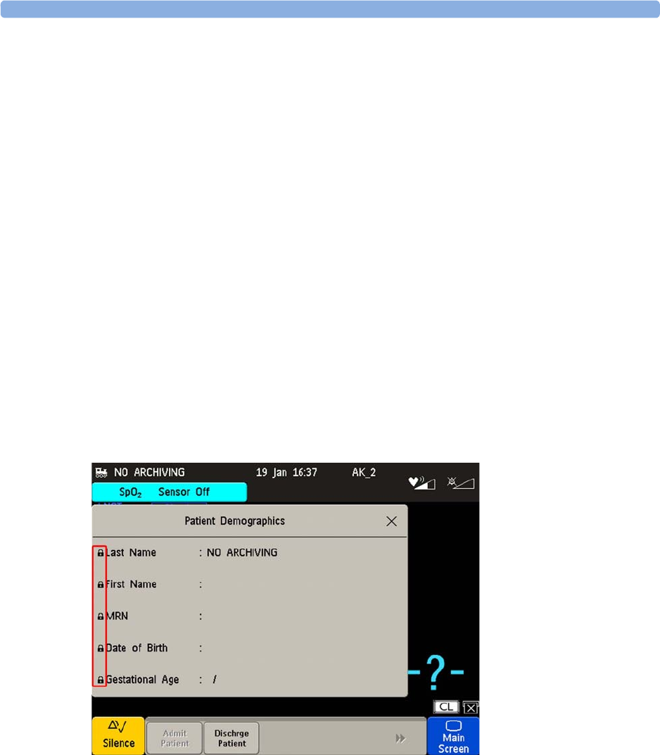
8 Admitting and Discharging
149
New Patient Check
The fetal monitor can be configured to ask you in certain situations:
• after a specified power-off period
• after a specified standby period
whether a new patient is now being monitored. The pop-up window is entitled
Is this a New Patient?
.
The monitor offers a
Yes
key, to discharge the previous patient and begin monitoring a new patient,
and a
No
key, to continue monitoring with the current patient data and settings.
The time periods for the two conditions can be configured independently.
OB TraceVue/IntelliSpace Perinatal
When the monitor is connected to an OB TraceVue/IntelliSpace Perinatal system over a LAN
connection, it has the control over patient demographic data. All patient and location-related data
visible on the monitor is set, overwritten, or updated by the OB TraceVue/IntelliSpace Perinatal
system. In the
Patient Demographics
window, a padlock symbol before the patient identification fields
indicates the locked state. The locked state prevents the reuse of the monitor for another patient, until
the current patient is discharged, and the monitor is freed through the OB TraceVue/IntelliSpace
Perinatal system. Locked fields remain locked when system connectivity is lost, until the monitor is
freed by discharging the patient. See the OB TraceVue/IntelliSpace Perinatal Instructions for Use for
details.
Transferring a Patient
When you are transferring a patient from one bed to another, both the monitor from which you are
transferring her and the monitor to which you are transferring her must be switched on and connected
to the OB TraceVue/IntelliSpace Perinatal network during the patient transfer.

8 Admitting and Discharging
150
OB TraceVue/IntelliSpace Perinatal via RS232
In contrast to a LAN connection, when the monitor is connected to an OB TraceVue/IntelliSpace
Perinatal system over an RS232 connection, the OB TraceVue/IntelliSpace Perinatal system does not
have full control over the monitor's patient admission and discharge functions.
Depending on how OB TraceVue/IntelliSpace Perinatal is configured, either the
Last Name
,
First Name
,
and the bed label, or just the bed label alone, are taken from the OB TraceVue/IntelliSpace Perinatal
system. See the OB TraceVue/IntelliSpace Perinatal Instructions for Use for details.

9
151
9Non-Stress Test Timer
The non-stress test (
NST
) timer shows the elapsed time for the non-stress test. The timer counts up to
the time you set for the NST.
Setting NST Autostart/Autostop
You can set the recorder so that it starts automatically (
NST Autostart
) when the NST timer is started,
and stops automatically (
NST Autostop
) when the NST is complete (when the set run time has elapsed).
As default,
NST Autostart
is
On
, and
NST Autostop
is
Off
.
Viewing the NST Timer
You can configure the timer notification symbol, (the NST label), a progress bar and the elapsed time
to be displayed in the top left-hand corner of the screen. By default, the NST timer is not displayed on
the screen.
Alternatively, you can view the timer in the
Timers
window.
To open the
Timers
window:
Either
• Press the
Timer
SmartKey.
Or
• Access the NST pop-up keys (see “Accessing the NST Setup Pop-up Keys” on page 152), and
press the
Timers
key.
Timer Expiry Notification
When the timer expires, the color changes from blue to green, you hear a single tone, and a message
appears in the status line on the main screen.
The volume of the tone can be set in Configuration Mode.

9 Non-Stress Test Timer
152
Accessing the NST Setup Pop-up Keys
You control and set up the NST timer (for example, start, stop, or clear the timer, and set the run time)
using a selection of pop-up keys that you access via any one of three possible routes:
• Via the
Timer
SmartKey (Route 1)
• Via the
Main Setup
SmartKey (Route 2)
• Via the NST display area at the top left-hand corner of the screen (Route 3). When you touch the
NST display area, the NST pop-up keys become available at the bottom of the screen.
Via the Timer SmartKey (Route 1)
Press the
Timer
SmartKey. The
Timers
window opens, and the pop-up keys for controlling/setting up
the NST timer appear (see “Pop-up Keys for NST Timer Setup” on page 152).
Via the Main Setup SmartKey (Route 2)
1Enter the
Main Setup
menu using the SmartKey.
2Select
NST
to enter the
Setup NST
menu. At the same time, the pop-up keys for setting up the NST
timer appear (see “Pop-up Keys for NST Timer Setup” on page 152).
Via the NST Display Area (Route 3)
Select the NST display area at the top left-hand corner of the screen (when so configured). The pop-up
keys for controlling/setting up the NST timer become available at the bottom of the screen (see “Pop-
up Keys for NST Timer Setup” on page 152).
Pop-up Keys for NST Timer Setup
Runtime
The run time can be set from 10 to 60 minutes. See the Configuration Guide for details how to set the
run time.
Run Time
The run time can be set from 10 to 60 minutes. See the Configuration Guide for details how to set the
run time.
Pop-Up Keys Selecting this pop-up key lets you: Comments
Start
Start the timer.
Stop
Stop the timer, allowing either restarting after a
pause (
Start
) or clearing (
Clear
key).
Setup NST
Enter the
Setup NST
menu. From here you can set
the run time.
This pop-up key is not available with
Route 2, as the
Setup NST
menu is
already open.
Timer
Return to the
Timers
window. This pop-up key is not available with
Route 1, as the
Timers
window is already
open.

10
153
10Non-Stress Test Report
It is generally accepted that a non stress test (
NST
) allows you to assess fetal well-being. The monitor's
NST report process uses fetal ultrasound (but not DECG) heart rate traces and the Maternal Toco
trace to generate a printed report when criteria are met and it is an indication of the fetal well-being.
The American term Non Stress Test (NST) is used for antepartum testing. The interpretation
algorithm and rule set are equivalent to those implemented in OB TraceVue Revision G.xx or
IntelliSpace Perinatal Revision H.xx and higher, and are based on the 2008 NICHD guidelines.
An NST report is a diagnostic aid, but it does not replace the clinician’s judgment. The interpretation
and the appropriate clinical response remain with the clinician.
A fetus normally produces characteristic heart rate patterns. Average baseline variability and
acceleration of the FHR in response to fetal movement are considered reassuring signs. This test does
not take into account any form of external fetal stimulation.
For every active ultrasound fetal heart rate measurement, one NST report can reside in the monitor’s
memory. The reports are cleared when you discharge a patient and when you start a new NST report.
When the NST Report option is available and the
NST Report
feature is "on", the NST status for all
available ultrasound fetal heart rate measurements are displayed on the screen.
The minimum displayed information is:
• NST identification (by FHR number: 1, 2, 3)
• Current NST status (by color: inverse for "not started yet", white for "running", yellow for
"stopped", green for "finished")
Setting Up an NST Report
To set up NST Report functionality:
1Enter the
Main Setup
menu and select the
NST Report
.
2Or select the
NST Report
SmartKey.
3Press the
Setup
pop-up key.

10 Non-Stress Test Report
154
4Set your configuration options.
Select from:
•
NST Analysis
choose from
On
or
Off
.
This switches the report feature on or off. This is linked to the NST timer. Both must be set to
On
for the NST report to function.
•
Report Recording
choose from:
–
Manual
- press the
Record Report
pop-up key to trigger a manual request.
–
After Recorder Stop
- report is recorded as soon as recorder becomes idle.
–
Immediately
- if a realtime recording is running, the monitor pauses it. The recording is
continued after the report has been recorded.
Average short term variability (STV) value is documented in [bpm] and [ms] if STV is configured as
part of the NST Report. This parameter is not considered as reassuring criteria.
NST Report Status Window
The
NST Report
window displays a detailed overview of the current NST status for any available
ultrasound fetal heart rate measurement. You can see:
• NST Status - whether it is ready, ongoing, or the time and date at which it was stopped, or at which
it was finished.
• Elapsed time - the time that has elapsed since the NST began.
• Accelerations - the number of FHR accelerations detected so far.
• Baseline - the average baseline value.
• Variability - the average variability value.
• Short Term Variability - the current short term variability (STV) value.
• Decelerations - the number of FHR decelerations detected so far.
• FHR Availability - current statistical FHR availability value.
• Sinusoidal - the current status of sinusoidal rhythm detection.
For criteria not yet met, a white arrow symbol marks the overall status on the top line, and also appears
against every criterion not yet met. A yellow symbol indicates detection of severe or prolonged
decelerations.
The pop-up keys let you perform the following actions:
•
FHR1
,
FHR2
,
FHR3
- switch to the window showing the current NST status for the fetal heart rate.
•
Record Report
- print the NST Report on paper.
•
Record Trace
- record the trace episode that belongs to the current report. Depending on device
usage, the trace recording might be incomplete.
•
Setup
- open the
Setup NST Report
window.

10 Non-Stress Test Report
155
Example NST Report
Field Field Content
Report Title, with FHR label
and date
NST Report for FHR1 on 12 Oct. 2009
Product Information Product DE53102345 G.01.70, OB A.04.24,
Toco DE52401090, FHR1 DE00002345 A.05.26
Patient Information Rogers, Alice
Age
: 27
Gestational Age:
Week
34,
Day
5
Start time, end time, Elapsed
time, configured runtime
Time: 11:34 – 12:06
Elapsed time: 32
min
Run time: 20
min
Overall one-line NST result
summary
NST Criteria*: not met
Title Trace Interpretation Summary
Result Accelerations Accelerations: 2
at: 11:59 12:02
Result: Contractions Contractions: 3
at: 11:57 12:00 12:04
Result: Baseline and
Variability
Baseline: 125 bpm (Range: 118-129 bpm)
Variability: 23 bpm (Range: 20-24 bpm)
Statistics: FHR availability FHR available: 95%
Result: Decelerations Decelerations: 1
at: 11:58
severe
prolonged
Result:
Sinusoidal Rhythm detected
Sinusoidal: No
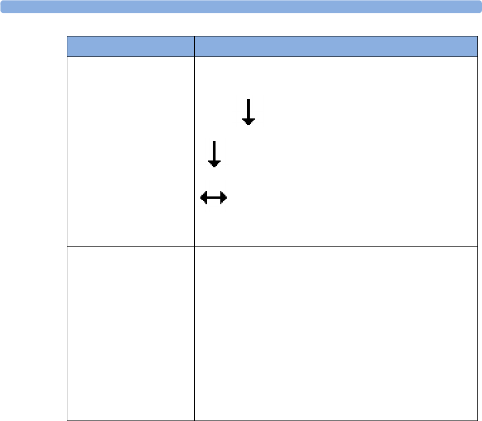
10 Non-Stress Test Report
156
Result: Decelerations before
Reporting Period
Events before Reporting Period:
Decelerations: 1
at: 11:38
severe
prolonged
This field is enabled if there were decelerations between the start of
NST and the start of the reporting period.
Guideline/Criteria
Information
(*) Interpretation criteria based on guideline "NICHD 2008, v01"
User-defined criteria for CTG tracing:
• valid FHR for 90% of reporting period
• baseline heart rate between 120 bpm and 160 bpm
• at least 2 accelerations in 10 min
• not more than 1 decelerations
• moderate baseline variability (6-25 bpm)
Additional criteria:
• no severe or prolonged decelerations
• no sinusoidal pattern in reporting period
Field Field Content

10 Non-Stress Test Report
157
NST Criteria
The patient is monitored for a user-definable period of time (10-60 minutes in steps of 5 minutes). The
test is considered reassuring when the following criteria are met:
• The fetal heart rate is valid at least 90% (this is configurable) of the specified time span.
• The FHR features a user-defined minimum number of accelerations.
• The FHR features a user-defined maximum number of tolerated decelerations, and does not
include severe or prolonged decelerations, which are never tolerated.
• The average baseline fetal heart rate lies within the user-defined limits for low heart rate and high
heart rate over the whole time span.
• The FHR exhibits a moderate variability (user-defined) for the specified time span.
An NST Report is generated when the reassuring criteria are met the first time in the current
monitoring phase. When performing NST with twins or triplets, a separate NST Report is generated
for each fetus.
After the reassurance criteria have been met, the clinician can print the NST Report and then turn the
fetal monitor off, or may continue fetal monitoring and print the report at any time.
Non-Reassuring Report
If the reassurance criteria are not met when the test has run for 90 minutes, or if you stop anytime
during the 90 minute period, then the test is stopped, and a report is generated stating the reassurance
criteria have not been met.
Nonreactive NST Test
If a nonreactive test occurs, and you then use acoustic stimulation, you must exercise caution in
interpreting the resulting traces, as artificial stimulation is not taken into account when calculating test
results.

10 Non-Stress Test Report
158

11
159
11Cross-Channel Verification
(CCV)
The cross-channel verification helps to reduce the possibility of misidentification of the maternal heart
rate for the fetal heart rate. It does this by comparing the measured fetal heart rate to the maternal
heart rate. If there are multiple fetal rates, they are also compared with each other and the maternal
heart rate.
Misidentification of Heart Rates
FHR detection by the monitor may not always indicate that the fetus is alive. Confirm fetal life before
monitoring, and continue to confirm that the fetus is the signal source for the recorded fetal heart rate
(see “Confirm Fetal Life Before Using the Monitor” on page 10).
To reduce the possibility of mistaking the maternal HR or pulse for FHR, or FHR1 for FHR2 or
FHR3, it is recommended that you monitor both maternal HR/pulse and the heart rates of all fetuses
(see “Monitoring FHR and FMP Using Ultrasound” on page 165, “Monitoring Twin FHRs” on
page 183, “Monitoring Triple FHRs” on page 191, and “Monitoring Maternal Heart / Pulse Rate” on
page 221).
Here are some examples where the maternal HR can be misidentified as the FHR, or one FHR for
another FHR (twins/triplets).
When using an ultrasound transducer:
– It is possible to pick up maternal signal sources, such as the maternal heart, aorta, or other
large vessels. Especially if the recorded maternal HR, and any other artifact is over 100 bpm.
– It is possible to pick up the same fetal heart rate simultaneously with multiple transducers.
NOTE
When an ultrasound transducer is connected to the monitor, but not applied to the patient, the
measurement may generate unexpected intermittent FHR readings.

11 Cross-Channel Verification (CCV)
160
When Fetal Movement Profile (FMP) is enabled:
The FMP annotations on a fetal trace alone may not always indicate that the fetus is alive. For
example, FMP annotations in the absence of fetal life may be a result of:
• Movement of the deceased fetus during or following maternal movement.
• Movement of the deceased fetus during or following manual palpation of fetal position (especially
if the pressure applied is too forceful).
• Movement of the ultrasound transducer.
When using a scalp electrode (DECG):
• Electrical impulses from the maternal heart can be transmitted to the fetal monitor through a
recently deceased fetus via the spiral scalp electrode, appearing to be a fetal signal source.
Cross-Channel Verification Functionality
The cross-channel verification functionality (CCV) of the fetal monitors compares all monitored heart
rates (maternal and fetal), and indicates automatically whether any two channels are picking up the
same signal, or monitoring similar values.
If the fetal monitor detects that any channels have the same or similar values, the
Coincidence
INOP is
issued with an INOP tone that can have a configurable delay. In addition, yellow question marks
appear next to the numerics on the touchscreen that have the same or similar values. On the recording
trace there is also a question mark from the point where recorded traces continuously overlap.
Visual Aids for CCV Detection
Coincidence
INOP appears on the screen of the fetal monitor.
Question mark appears on the screen of the fetal monitor next to the
numerics that show the same or similar values.
Question mark recorded on the trace from the point where two
measured values coincide.

11 Cross-Channel Verification (CCV)
161
Overview of Cross-Channel Comparisons
Measurements from Transducers
Measurement Comparison Done by the Fetal Monitor for Cross-Channel Verification
* dFHR and aFHR always replace one of the fetal channels (1,2, or 3) and cannot be compared to the
channel it replaces. If you monitor for example twins with two ultrasound transducers, you see the
numerics FHR1 and FHR2 at the monitor. If you decide to replace the ultrasound transducer for
FHR2 with a fetal scalp electrode, the dFHR numeric is then shown as dFHR2.
Measurement Transducer
FHR (US) From Ultrasound or CL Ultrasound transducer
dFHR (DECG) From a fetal scalp electrode
aFHR (abdom. ECG) From the CL Fetal & Maternal Pod
Pulse (Toco) From Toco MP, or CL Toco+ MP transducer
Pulse (SpO2) From SpO2 or CL SpO2 Pod
HR (MECG) From MECG electrodes
aHR (abdom. ECG) From the CL Fetal & Maternal Pod
FHR1 (US) FHR2 (US) FHR3 (US) dFHR (DECG)* aFHR* (ECG)
FHR1 (US)
FHR2 (US)
FHR3 (US)
dFHR (DECG)*
aFHR (abdom. ECG)
Pulse (Toco)
Pulse (SpO2)
HR (MECG)
aHR (abdom. ECG)
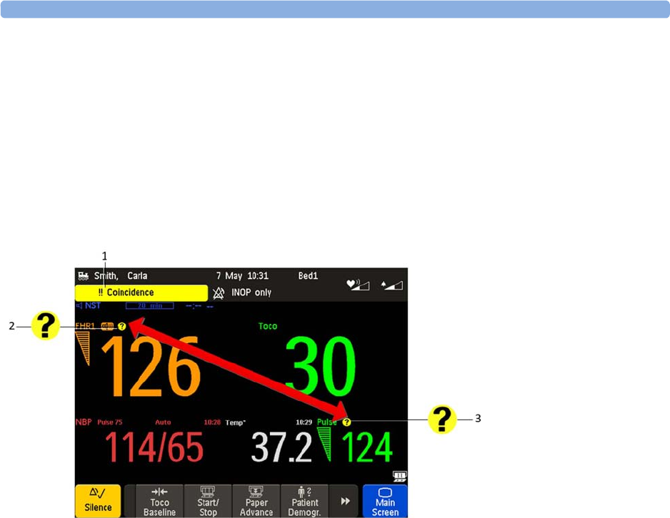
11 Cross-Channel Verification (CCV)
162
Coincidence Examples
Coincidence of Maternal Pulse and FHR
When the maternal pulse and FHR are being monitored, and the measured values are very similar or
the same, the coincidence question mark is displayed on the monitor’s screen above both of the
corresponding numerics (in this case maternal pulse and FHR). Often the signal loss or coincidence
happens because the fetal or maternal movement displaced the ultrasound transducer, and a
repositioning of the transducer is necessary.
Pulse Delay
SpO2 pulse rate traces have an averaging calculation of approximately 10 seconds and an overall delay
of approximately 12 seconds (depending on recorder speed). This differs from a non-averaged beat-to-
beat MECG heart rate trace or an ultrasound heart rate trace calculation (having switched to the
maternal HR) with no significant delay. Note that Maternal Pulse from Toco has an averaging of
4 seconds and an overall delay of between 6 and 8 seconds.
1
Coincidence
INOP
2Coincidence question mark
above
FHR1
3Coincidence question mark
above pulse from Toco MP
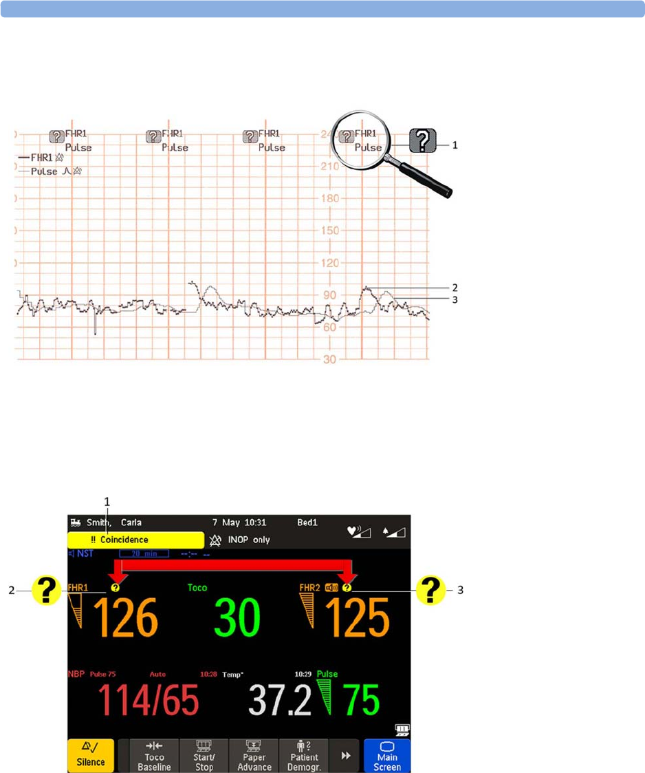
11 Cross-Channel Verification (CCV)
163
The coincidence question mark is also printed on the trace paper next to the corresponding FHR and
maternal pulse.
Coincidence of Twins/Triplets FHRs
When both
FHR1
and
FHR2
are being monitored, and the measured values are very similar or the same,
the coincidence question mark is displayed on the monitor’s screen above both of the corresponding
numerics (in this case
FHR1
and
FHR2
).
1Printed coincidence
question mark on trace
2Fetal heart rate trace from
Ultrasound
3Maternal pulse trace from
SpO2
1
Coincidence
INOP
2Coincidence question
mark above
FHR1
3Coincidence question
mark above
FHR2
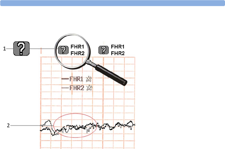
11 Cross-Channel Verification (CCV)
164
The coincidence question mark is also printed on the trace paper next to
FHR1
and
FHR2
.
Recommended Actions for Coincidence INOP
1Confirm fetal life by palpation of fetal movement or auscultation of fetal heart sounds using a
fetoscope, stethoscope, or Pinard stethoscope.
2Manual determination of the maternal pulse and comparison with the fetal heart rate sound signals
from the loudspeaker.
3Reposition the transducer, or ensure that the fetal scalp electrode is placed correctly, until you
receive a clear signal and the monitor is no longer issuing the
Coincidence
INOP.
4In case of difficulties deriving a stable maternal pulse reading using the Toco MP or CL Toco+ MP
transducer, use SpO2 or the CL SpO2 Pod instead. In case of similar problems with the pulse
measurement from SpO2, use MECG instead. Reasons to switch the method for deriving a
maternal pulse or heart rate include: motion artifacts, arrhythmia, and individual differences in
pulse signal quality on the abdominal skin (via Toco MP).
5If you cannot hear the fetal heart sounds, and you cannot confirm fetal movement by palpation,
confirm fetal life using obstetric ultrasonography.
1Printed coincidence question mark on
trace
2
FHR1
and
FHR2
traces

12
165
12Monitoring FHR and FMP
Using Ultrasound
To monitor a single FHR externally, you use an ultrasound transducer attached to a belt around the
mother's abdomen. The ultrasound transducer directs a low-energy ultrasound beam towards the fetal
heart and detects the reflected signal. Your monitor can also detect fetal movements and print the fetal
movement profile (
FMP
) on the trace. Monitoring using ultrasound is recommended from the
25th week of gestation for non-stress testing or routine fetal monitoring.
WARNING
Performing ultrasound imaging or Doppler flow measurements together with ultrasound fetal
monitoring may cause false FHR readings, and the trace recording may deteriorate.
Technical Description
Fetal monitors use the ultrasound Doppler method for externally monitoring the fetal heart rate. Using
the Doppler method, the transducer (in transmitter mode) sends sound waves into the body which are
then reflected by different tissues. These reflections (Doppler echoes) are picked up by the transducer
(in listening mode). These Doppler echoes are amplified and sent to the monitor’s speaker through
which the fetal heart signal can be heard. In parallel the Doppler echoes are processed through an
autocorrelation algorithm to determine the fetal heart rate (FHR). The FHR is displayed on the
monitor’s numeric display and on the recorded trace.
Properly representing the fetal heart rate using a device that derives heartbeats from motion is a
formidable task and the limitations of the technology will be discussed shortly. Basic fetal cardiac
physiology may contribute to difficulties in obtaining a reliable ultrasound signal.
A heart rate pattern of a fetus is capable of extraordinary variation, ranging from a stable pattern with
minimal variation while the fetus is “asleep” to robust accelerations of 40-60 bpm above baseline rate
over a few seconds, or exaggerated variability when the fetus is active. Decelerations of the rate
60-80 bpm below baseline may develop even more abruptly than the accelerations. Beat-to-beat
arrhythmias may further exaggerate the amount of “variability” and can be seen at the bottom of
variable decelerations, or in the presence of fetal breathing movements which also tend to lower the
fetal heart rate. The recognition of these normal variations in fetal heart rate patterns will greatly assist
in the separation of genuine fetal information from the artifact.

12 Monitoring FHR and FMP Using Ultrasound
166
Limitations of the Technology
All tissues moving towards or away from the transducer generate Doppler echoes. Therefore, the
resulting signal that is provided to the monitor’s speaker, and for further fetal heart signal processing,
can contain components of the beating fetal heart wall or valves, fetal movements, fetal breathing or
hiccup, maternal movements such as breathing or position changes, and pulsating maternal arteries.
The fetal heart signal processing uses an autocorrelation algorithm to obtain periodic events such as
heart beats. If the signal is erratic such as from a fetal arrhythmia, the ultrasound device may have
trouble tracking the abrupt changes, and may misrepresent the true FHR pattern. Signals such as those
from moving fetal limbs are usually very strong, thereby masking the fetal heart signal. During
prolonged movements where the fetal heart signal is masked, the FHR appears blank on the numeric
display and as a gap on the recorded trace. Fetal position changes, maternal position changes, or
uterine contractions can move the fetal heart partly or fully out of the ultrasound beam resulting in
signal loss, or even picking up Doppler echoes from pulsating maternal arteries. In these cases a
maternal heart rate or sometimes even a rate resulting from the mixture of fetal and maternal signals
may be displayed on the monitor’s numeric display and on the recorded trace.
In contrast to the timely well-defined R-peak of an ECG signal obtained with a fetal scalp electrode,
the ultrasound Doppler signal from a fetal heart consists of multiple components from atria (diastole),
ventricles (systole), valves, and pulsating arteries. These components vary depending on fetal and
transducer position and angle, and are further modulated by factors such as fetal or maternal breathing.
These effects may produce what is called “artifact”. Optimal transducer positioning therefore is key to
minimizing these effects and thereby minimizing artifact.
Misidentification of Maternal HR as FHR
FHR detection by the monitor may not always indicate that the fetus is alive. Confirm fetal life before
monitoring, and continue to confirm that the fetus is the signal source for the recorded heart rate (see
“Confirm Fetal Life Before Using the Monitor” on page 10 and “Cross-Channel Verification (CCV)”
on page 159).
What You Need
• Ultrasound transducer
• Toco MP or CL Toco+ MP transducer
• Ultrasound gel
• Transducer belt (and optional butterfly belt clip, if applicable)
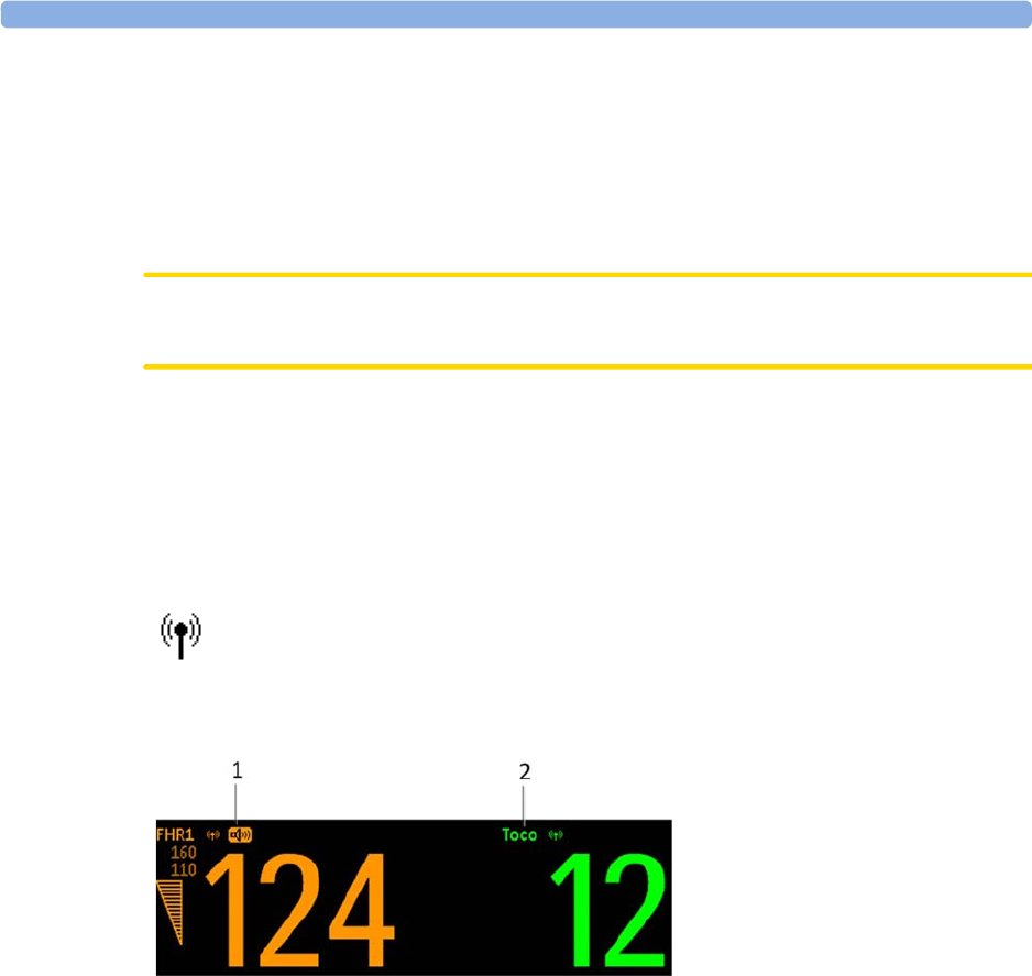
12 Monitoring FHR and FMP Using Ultrasound
167
Cableless Monitoring - Important Considerations
When using an Avalon CL or Avalon CTS Fetal Transducer system with your monitor, note the
following:
Refer to “Cableless Status Indication” on page 95 for general rules regarding the use of cableless
transducers from an Avalon CL or Avalon CTS Cableless Fetal Transducer system.
CAUTION
Never use ultrasound transducers connected to more than one fetal monitor on the same patient.
• When using an Avalon CL or Avalon CTS you should be aware that FMP is not recommended
when the mother is likely to move, and you should disable Fetal Movement Profile (FMP) on the
fetal monitor (
Fetal Movement
Off
) if the mother is walking. See also “Fetal Movement Profile” on
page 170.
• With the Avalon CL Transducer System, you can monitor twins and triplets with cableless
transducers. The Avalon CTS System does not have this option.
The wireless symbol appears next to the measurement label, indicating that the
measurement is being made by a cableless transducer.
1FHR1
2Toco parameter

12 Monitoring FHR and FMP Using Ultrasound
168
WARNING
• During ambulant FHR monitoring, the chance of losing the signal or detecting the maternal heart
rate is higher than during stationary monitoring. The frequency of the patient's walk may be
detected, and mistaken for an FHR signal.
• Check the mother’s pulse periodically during monitoring and compare this with the FHR signal.
Beware of mistaking a “doubled” maternal heart rate for FHR. If a fetus is dead, there is a risk that
the maternal heart rate is monitored and misinterpreted as the fetal heart rate. Therefore, the
simultaneous monitoring of maternal heart rate (preferably, the maternal ECG) and the fetal heart
rate is encouraged.
• Do not interpret maternal movements as fetal movements.
• Artifacts: FMP artifacts are generated during fetal heart rate searching by changing the transducer
position, therefore the fetal monitors enable the FMP only after detecting a valid heart rate signal
for several seconds. FMP is not recommended when the mother is likely to move, and you should
disable Fetal Movement Profile (FMP) at the fetal monitor (
Fetal Movement
Off
) if the mother is
walking.
• Gaps in maternal heart rate detection can occur:
– if the transducer is not correctly positioned.
– due to the pulsation of uterine blood vessels.
– if the fetus moves.
Preparing to Monitor
Prepare for ultrasound monitoring using the list below. The standard procedures in use in your facility
determine the sequence of actions.
1Determine fetal position.
2Fasten the belt around the patient.
3Switch on the monitor and the recorder.
4Connect the transducer to a free socket. The signal quality indicator for the heart rate initially
displays an invalid signal.
5Apply a thin layer of ultrasound gel to the underside of the transducer.
CAUTION
Using ultrasound gel not approved by Philips may reduce signal quality and may damage the
transducer. This type of damage is not covered by warranty.
1Place the transducer on the abdomen, if possible over the fetal back or below the level of the
umbilicus in a full-term pregnancy of cephalic presentation, or above the level of the umbilicus in
a full-term pregnancy of breech presentation. Work the transducer in a circular motion to ensure
the gel layer makes good contact.
2When the transducer is connected correctly and you receive a good signal, the signal quality
indicator should be filled out. If an inadequate signal is produced, the signal quality indicator will
indicate a poor signal, and no numeric will appear on the screen.

12 Monitoring FHR and FMP Using Ultrasound
169
3Adjust the audio volume of the monitor's loudspeaker to a clearly audible level, while moving the
transducer over the abdomen. When you have a good signal, secure the transducer in position
below the belt.
WARNING
Periodically compare the mother's pulse with the signal coming from the monitor's loudspeaker to
ensure that you are monitoring fetal heart rate. Do not mistake a doubled or elevated maternal HR for
FHR.
The ultrasound transducer may warm slightly (less than 1°C/1.8°F above ambient temperature) when
applied to the patient. When not applied, the transducer can reach a maximum temperature of 44°C/
112.2°F at an air temperature of 40°C/104°F.
Selecting Fetal Heart Sound
You can listen to the fetal heart sound from one ultrasound transducer at a time. When the fetal heart
sound is selected for an FHR channel, you see the audio source symbol next to the FHR numeric label
for that channel.
To select the audio source for an FHR channel:
1Enter the
Setup FHR1
menu for the channel you want to hear (FHR1 used as an example).
2Press
Select Audio
. It may take a few seconds for the audio source symbol to appear.
1FHR1
2Audio source symbol
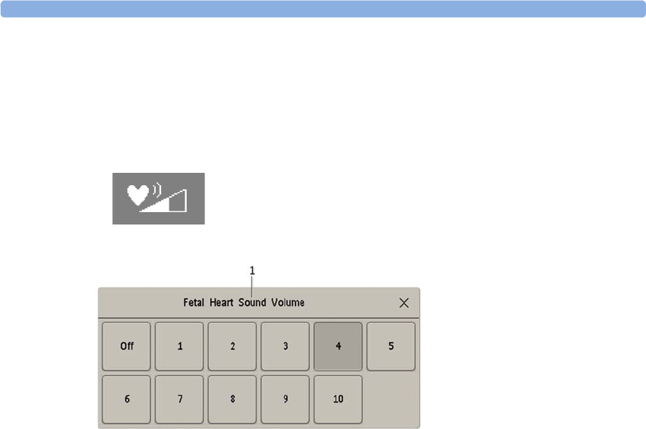
12 Monitoring FHR and FMP Using Ultrasound
170
Changing the Fetal Heart Sound Volume
The FHR volume symbol at the top right of the
Fetal Heart Sound Volume
window gives you an
indication of the current volume. To change the volume:
1Select the volume symbol. The volume scale pops up.
2Select the required volume from the volume scale.
Fetal Movement Profile
The Fetal Movement Profile (FMP) parameter detects fetal movements with an ultrasound transducer
connected to the monitor. Only the fetus monitored on the FHR1 channel is monitored for FMP.
Once you have enabled FMP (see “Switching FMP On and Off” on page 171), it is triggered
automatically whenever:
• You connect an ultrasound transducer.
• A patient is discharged.
When FMP is enabled, the ultrasound transducer detects most fetal body movements. Eye movements
are not detected, and movement of the feet and hands may not be detected. Positioning or
repositioning of the transducer is recorded as fetal movement. Maternal movement, excessive fetal
breathing, or fetal hiccups may also be recorded as fetal movement (also in case of fetal demise or
during the second stage of labor). You can mark these artifacts on the trace paper using either the
remote event marker, or the event marker key as described in “Marking an Event” on page 60. FMP
should be interpreted with care, or disabled when the patient is ambulating or during the second stage
of labor. Ignore these movements when you interpret the FMP. When monitoring twins or triplets,
only the fetus monitored on the FHR1 channel is monitored for movement, but be aware that
movements recorded for FHR1 may also be caused by movement of the second or third fetus.
The fetal movement profile (FMP) appears as "activity blocks" along the top of the Toco scale, the
length of each block showing the duration of the activity.
1
Fetal Heart Sound Volume
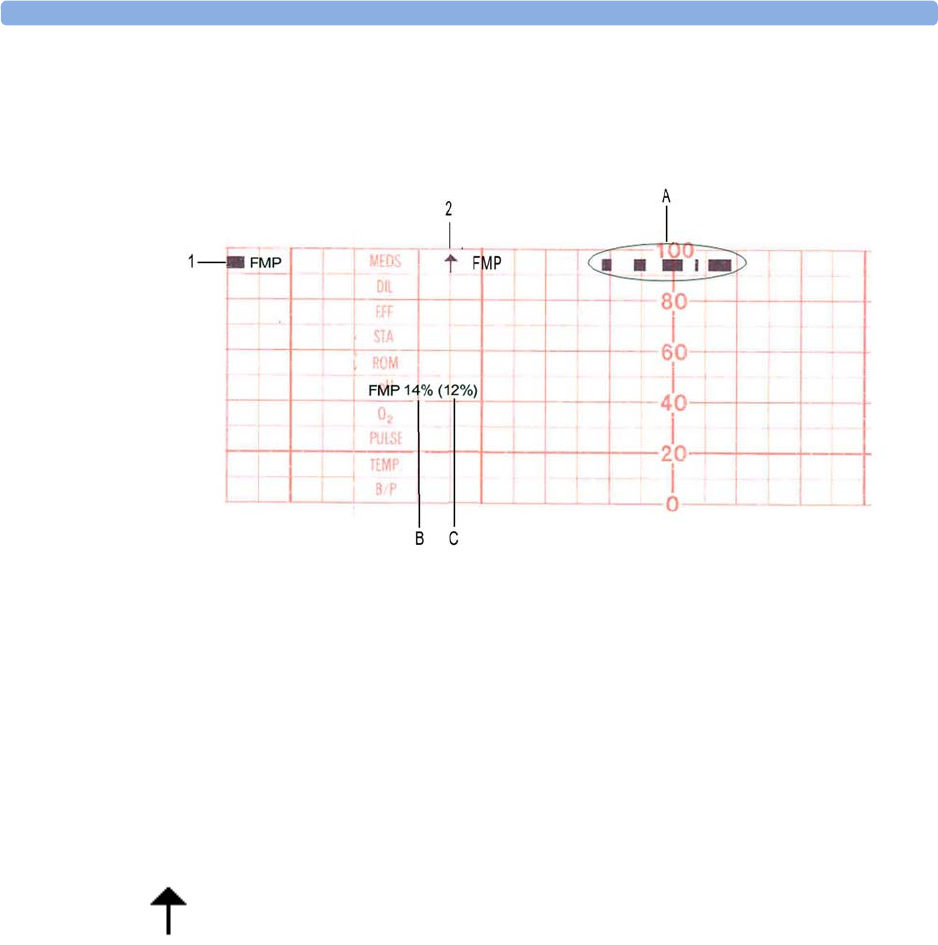
12 Monitoring FHR and FMP Using Ultrasound
171
FMP Statistics
FMP statistics are printed every ten minutes.
The FMP detection activates after about half a minute of steady heart rate signals (signal indicator half-
full, or full) to minimize transducer positioning artifact. You will notice this deliberate delay:
• When a new patient is admitted. A patient discharge restarts the FMP statistics from zero.
• When you connect an ultrasound transducer.
Switching FMP On and Off
You can switch FMP on and off from any FHR channel. For example, to set it from the FHR1
channel:
1Enter the
Setup FHR1
menu.
2Select
Fetal Movement
to switch between
On
and
Off
.
3Return to the main screen.
1FMP enabled
2FMP started here
AIndication of current fetal movement
BThe FMP statistics are presented as two percentage figures:
The first figure shows the percentage of detected fetal movements in the previous ten
minutes.
CThe second figure shows the percentage of detected fetal movements since the start of
recording.
To mark the start of the FMP statistic, FMP is printed on the paper with an arrow.

12 Monitoring FHR and FMP Using Ultrasound
172
Troubleshooting
Problem Possible Causes Solutions
Erratic trace
Erratic display
Fetal arrhythmia Consider monitoring FHR using DECG after
the rupture of membranes.
Obese patient
Transducer position not optimal Reposition transducer until signal quality
indicator shows a good signal (at least
half-full).
Belt loose Tighten belt
Too much gel Remove excess
Very active fetus -
Insufficient gel Use enough gel to ensure the transducer
makes good contact with the mother's skin.
Signal quality indicator is
continuously poor
Transducer position not optimal Reposition transducer until signal quality
indicator shows a good signal (at least
half-full).
FHR less than 50 bpm (and the FHR is
audible)
If membranes are ruptured, using a fetal scalp
electrode (FM30 and FM50 only) allows
measurement of FHR down to 30 bpm.
Questionable FHR Recording maternal HR by mistake Reposition transducer
Confirm fetal life
Recording periodic signals when the
transducer is not applied to the patient
Disconnect all NON-USED ultrasound
transducers, as continuous, regular
mechanical, or electromagnetic influences can
result in an artificial trace.
Recorded FHR appears to be suspiciously
higher, or suspiciously lower, than real FHR.
In very rare cases, half- or double-counting
of the FHR can occur.
If you have reason to question the validity of
the recorded FHR, always verify FHR by
independent means (by auscultation, for
example). Measure maternal pulse by
independent means.
FHR not recorded FHR is less than 50 bpm or over 240 bpm If membranes are ruptured, using a fetal scalp
electrode (FM30 and FM50 only) allows
measurement of FHR down to 30 bpm.
If FHR is outside of the specified range, verify
FHR by independent means.
FHR1 Equip Malf
or
FHR2 Equip Malf
or
FHR3 Equip Malf
INOP displayed. See “Patient Alarms and INOPs” on
page 129.
FHR1 Signal Loss
or
FHR2 Signal Loss
or
FHR3 Signal Loss
INOP
displayed.
FHR1 Unplugged
or
FHR2 Unplugged
or
FHR3 Unplugged
INOP
displayed.
If you suspect the transducer is malfunctioning Test the transducer.
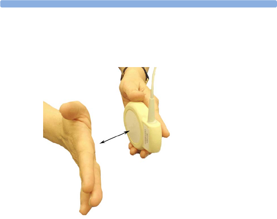
12 Monitoring FHR and FMP Using Ultrasound
173
Testing Ultrasound Transducers
If any of the following tests fail, repeat the test using another transducer. If the second transducer
passes the tests, confirming that the first transducer is defective, contact your service personnel.
If the second transducer also fails the tests, contact your service personnel.
You can test all ultrasound transducers, including the cableless ones, as described above.
Additional Information
Artifact in Fetal Heart Rate Measurement
How to detect it and reduce its occurrence using the Avalon Fetal Monitor
The ultrasound derived FHR measurement technique in Avalon fetal monitors, like all other
ultrasound fetal monitors’ FHR measurement techniques, has limitations that can lead to
misrepresentation of the fetal heart rate pattern and potential misinterpretation of the fetal condition.
An incorrect interpretation of the trace may lead to either unnecessary interventions, or to failure to
detect fetal distress, and the need for intervention. Thus, the on-going evaluation of the recorded trace
requires regular confirmation that the trace represents the true FHR. Specific situations requiring such
confirmation include the following:
• After starting a measurement or changing a transducer
• After maternal position changes, for example during pushing with contractions
• When the tracing shows abrupt changes in baseline rate, variability, or pattern (decelerations to
accelerations) especially in the second stage of labor
• When the baseline maternal heart rate is within about 15 bpm of the FHR
To test an ultrasound transducer:
1Switch on the monitor and the
recorder.
2Connect the transducer to the fetal
monitor.
3Select the fetal heart sound for this
channel.
4Increase the loudspeaker volume
to an audible level.
5Holding the transducer in one
hand, move your other hand
repeatedly towards and then away
from the surface.
6Check that a noise is heard from
the loudspeaker.

12 Monitoring FHR and FMP Using Ultrasound
174
• When you are unable to determine a baseline rate, and variability occurs between consecutive
contractions
There are several ways to verify the source and/or accuracy of the recorded fetal heart rate pattern.
These include:
Verification of the FHR with:
• An obstetric stethoscope
• Ultrasound imaging
• A fetal scalp electrode
Verification of the maternal heart rate:
• Using pulse oximetry - for a maternal heart rate pattern displayed simultaneously with the FHR
(Cross-Channel Verification (CCV) feature)
• Using Maternal ECG - for a maternal heart rate pattern displayed simultaneously with the FHR
(CCV feature)
• Manual determination of the maternal pulse
Whenever possible measure the maternal pulse rate to make use of the monitor’s Cross-Channel
Verification (CCV) feature, especially during the second stage of labor, or when the maternal pulse is
elevated over 100 bpm. The Avalon fetal monitor provides a Toco MP or CL Toco+ MP transducer
for maternal pulse detection and the creation of a maternal heart rate pattern plotted on the same
recorder as the FHR pattern. In case of difficulties deriving a stable maternal pulse reading using the
Toco MP or CL Toco+ MP transducer, use SpO2 or MECG instead.
When either of these parameters is utilized, the monitor will automatically and continuously perform a
CCV of the maternal heart rate pattern against the FHR pattern displayed on the monitor. If the
patterns and rates are similar, the CCV provides an alarm that both rates are probably from the same
source (i.e., they both represent the maternal heart rate pattern and the fetus is not being monitored).
Repositioning the ultrasound transducer will usually correct this, but it may be necessary to apply a
fetal scalp electrode. Advising the mother to temporarily cease pushing during contractions may help
to more rapidly resolve any uncertainty in this situation.
Doubling: The autocorrelation algorithm can display a doubled fetal or maternal heart rate if the
duration of diastole and systole are similar to each other, and if the heart rate is below 120 bpm.
Doubling, usually brief, is accompanied by an abrupt switch of the trace to double the baseline value.
Halving: With fetal tachycardia (above 180 bpm) and some interference from breathing or maternal
arteries the autocorrelation algorithm may only recognize every second beat resulting in a halved rate
for a limited time. If the actual FHR is above the maximum limit of the monitor (240 bpm), the
algorithm will also half-count. Halving is accompanied by an abrupt switch of the trace to exactly half
the prior baseline value. This switch may simulate an FHR deceleration and be referred to by clinicians
as a “false deceleration.”
Switching to maternal heart rate (also referred to as "Maternal Insertion"): The fetal heart can
move partly or fully out of the ultrasound beam and the autocorrelation algorithm may then pick up
and display the maternal heart rate. Depending on the signal mix in the ultrasound signal, switching to
the maternal heart rate may mimic several conditions with the potential for erroneous interpretation
and response as follows:
•The switch to the maternal heart rate may simulate an FHR deceleration (i.e., a decrease of
the fetal heart rate, and be referred to by clinicians as a “false deceleration”).

12 Monitoring FHR and FMP Using Ultrasound
175
•The maternal heart rate may simulate a normal fetal heart rate pattern (i.e., it may mask an
FHR deceleration or fetal demise).
Especially during pushing with contractions in the second stage of labor, the maternal heart rate
may increase to the point where it may equal or exceed the fetal rate. Here the maternal trace may
mimic a normal fetal trace while the fetus may be having decelerations or fetal demise has
occurred. This change from fetal to maternal heart rate pattern may not be at all obvious unless
CCV is used and represents the most dangerous pitfall of all the artifacts because fetal distress may
go unrecognized.
•The maternal heart rate may simulate an FHR acceleration, which is an increase of the fetal
heart rate.
During expulsive efforts, the maternal heart rate normally accelerates and may be at or above the
normal FHR range.
•The FHR may display gradual appearing decelerations. Generally, the “false decelerations”
described above are abrupt. Rarely, combinations of “noisy/erratic signal” associated with changes
in maternal and/or fetal rate or movement will produce more gradual appearing “false
decelerations” but these are usually short-lived with an abrupt return to an obviously stable FHR
baseline.
“Noisy/Erratic” signals: With mixed or weak signals the tracing may reveal very brief episodes of
erratic recorded traces. These represent the autocorrelation algorithm finding brief sequences of
apparent and persistent heartbeats amidst a mixed or weak signal. These erratic recorded traces are
commonplace, especially in association with fetal or maternal movement. During prolonged periods
of such noisy/erratic signals, the fetus is not being adequately monitored.
Drop out: With mixed or weak signals there may be no heart rate tracing at all. These episodes reflect
that if the algorithm does not find an apparent and persistent heartbeat amidst a mixed or weak signal,
it will not print a heart rate on the tracing. Brief episodes of drop out are commonplace, especially in
association with fetal or maternal movement. During prolonged periods of drop out, the fetus is
not being adequately monitored.
Multiple Fetuses
With multiple fetuses, the potential to experience these artifacts is increased. Positioning of the
transducer is even more critical. Ultrasound scanning should be used to help with positioning of
individual transducers. See also “Monitoring Twin FHRs” on page 183 and “Monitoring Triple FHRs”
on page 191.

12 Monitoring FHR and FMP Using Ultrasound
176
Obtaining a Good Heart Signal
To successfully position the ultrasound transducer, first determine the fetal position using palpation.
Position the transducer over the strongest audible fetal heart sound from the monitor’s speaker and
wait at least six seconds after each transducer adjustment to verify a good signal quality displayed
on the Signal Quality Indicator and a consistent FHR numeric display. Having determined the position
that provides a strong fetal signal, fix the transducer on the abdomen with the belt.
If the quality of the signal or the appearance of the heart rate trace from the ultrasound transducer is
questionable, the transducer should be repositioned as described above. Alternatively, the use of an
ultrasound scanner will greatly facilitate the determination of the optimal site for the ultrasound heart
rate transducer. Factors during the second stage of labor that may influence the quality of the FHR
tracing obtained with ultrasound include:
• Uterine contractions
• Changing contour of the maternal abdomen
• Maternal body movement - positioning
• Maternal expulsive efforts - pushing
• Maternal tachycardia/accelerations with contractions
• Fetal decelerations, Fetal tachycardia
• Delayed return of the fetal heart rate from a deceleration
• Descent of the fetus in the birth canal
• Rotation of the fetus in the birth canal
In some cases during the second stage of labor, a good and reliable ultrasound FHR signal may not be
obtainable, and the use of a fetal scalp electrode must be considered (fetal ECG).
Heart Rate Sound
The heart rate sound emitted by the device is a representation of movement that, in most cases,
permits accurate auscultation of the FHR corresponding to the FHR displayed on the monitor and rate
pattern depicted on the trace recording. On occasion, the user may hear an FHR that differs from the
FHR display and the recorded trace. This may occur in situations where the fetal heart moves partly
out of the transducer ultrasound beam. In these cases, the user may hear the FHR emitted from the
monitor’s speaker, even though another periodic signal (usually the maternal heart rate) has become
stronger. The autocorrelation algorithm will display the stronger maternal heart rate, despite the
persistence of a weaker fetal signal. These occurrences are usually very brief and, if persistent, can be
addressed by repositioning the transducer.
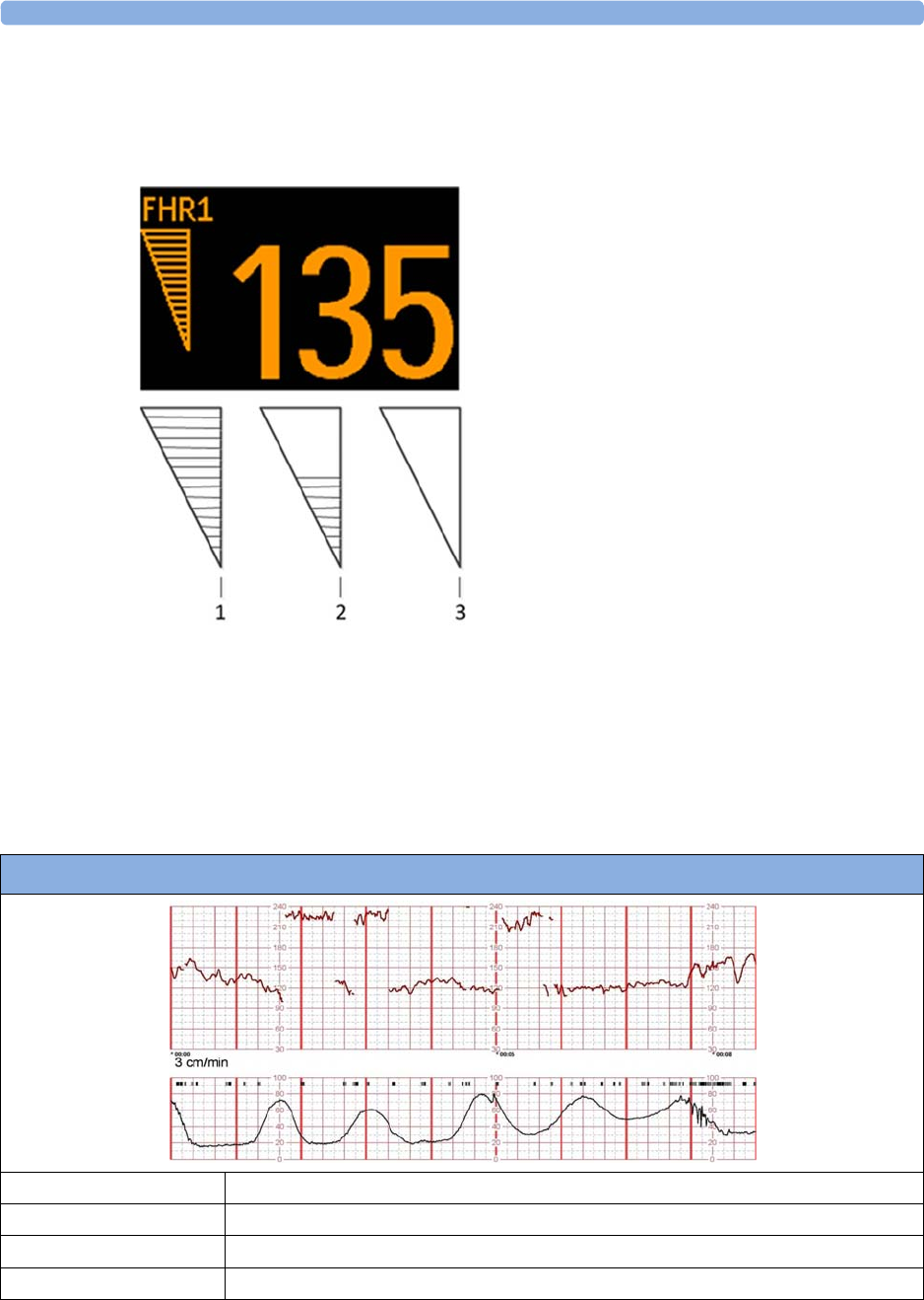
12 Monitoring FHR and FMP Using Ultrasound
177
Signal Quality Indicator
The signal quality on the Avalon fetal monitor is indicated by a triangle on the touchscreen that is
displayed in one of three ways:
Examples of Artifacts
When monitoring the maternal ECG, a beat-to-beat maternal heart rate trace is printed alongside the
FHR recorded trace. When monitoring the maternal SpO2 derived pulse rate, a filtered and averaged
heart rate trace is printed.
Following are recorded trace examples of complaints received regarding inaccurate output from the
Avalon monitors. Scaling is 3 cm/min and 30 bpm/cm.
1Completely filled triangle, indicating good signal
quality (good/full).
2Half-filled triangle, indicating limited signal quality.
This condition may indicate a weak or ambiguous
signal. If this status persists, reposition the
transducer (acceptable/medium).
3Empty triangle, indicating insufficient signal
quality. No FHR is displayed on the monitor’s
numeric display or the recorded trace. If this status
persists, reposition the transducer (poor/no signal).
Double-Counting
Baseline Rate 120
Baseline Variability Moderate
Accelerations Present
Decelerations Not apparent
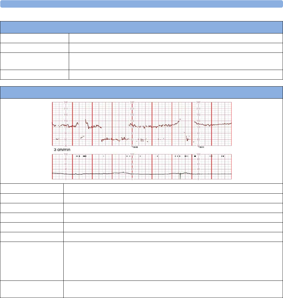
12 Monitoring FHR and FMP Using Ultrasound
178
Contractions Excessive, coupling, hypertonus
Artifact Double-Counting
Comment Reassuring tracing. The excessive uterine activity should prompt discontinuation of any
oxytocic agent.
Remediation The true fetal rate can be confirmed by auscultation or by fetal scalp electrode.
Double-Counting
Half-Counting
Baseline Rate 120
Baseline Variability Moderate
Accelerations Present
Decelerations Not apparent
Contractions Minimal
Artifact Half-counting, noise, drop out
Comment Reassuring tracing. The half-count at 4-5 minutes into the tracing may simulate a fetal
deceleration, but the abruptness and the lack of any compensatory changes when the
normal rate returns suggests that this is half-counting. Insertion of the maternal heart rate
(see below) may produce a similar pattern. Note also very brief episodes of half-counting,
maternal insertion, and signal dropout.
Remediation Auscultation or the application of a direct scalp electrode, if feasible, will reveal the true
fetal heart rate.
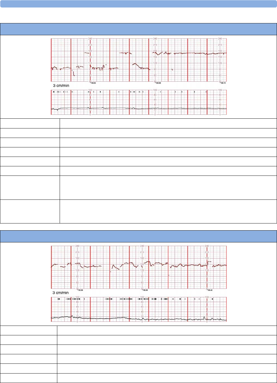
12 Monitoring FHR and FMP Using Ultrasound
179
Maternal-Switching (Maternal Insertion)
Baseline Rate 170 - Tachycardia
Baseline Variability Moderate
Accelerations Unable to determine
Decelerations Absent
Contractions Absent
Artifact Maternal insertion, noise
Comment The fetus has an elevated baseline rate of about 170 bpm with minimal to moderate
variability. The ability to assess fetal status is limited because about half of the tracing
displays the maternal heart rate.
Remediation The application of a maternal transducer (ECG or pulse oximeter) will likely resolve any
possible confusion with the tracing. Repositioning the transducer may produce a more
reliable tracing. Consideration must also be given to applying a fetal scalp electrode.
Noisy/Erratic Signal and Dropout
Baseline Rate 140
Baseline Variability Moderate
Accelerations Present
Decelerations Absent
Contractions Minimal
Artifact Noisy signal, drop-out

12 Monitoring FHR and FMP Using Ultrasound
180
Selection of Literature References on Artifacts
___________________________________________________________
Mosby's Pocket Guide to Fetal Monitoring: A Multidisciplinary Approach (Nursing Pocket
Guides) 8th Edition (May 2016).
Lisa A. Miller, David A. Miller, Rebecca L. Cypher
Elsevier Ltd, Oxford. 2017, ISBN 978-0-323-40157-9
___________________________________________________________
Signal ambiguity resulting in unexpected outcome with external fetal heart rate monitoring
By Duncan R. Neilson Jr, MD; Roger K. Freeman, MD; Shelora Mangan, RNC, MSN, CNS
American Journal of Obstetrics & Gynecology, June 2008
___________________________________________________________
Antepartal and Intrapartal Fetal Monitoring, 3rd Edition (2007)
By Michelle L. Murray, PhD, RNC
Springer Publishing Company, ISBN 0-8261-3262-6
Page 2, Table 2: Limitations of Continuous EFM
Item 15: “The US may detect maternal aortic wall movement and the maternal HR will be printed. A
failure to recognize the lack of an FHR may delay appropriate management.”
Page 38, “Solving Equipment Problems”, Table 3: The Ultrasound Transducer
___________________________________________________________
JOGC (Journal of Obstetrics and Gynecology Canada)
Volume 29, Number 9, September 2007
Chapter 2: Intrapartum Surveillance
Page S35: “Methods of Electronic Fetal Monitoring”
“… Among its disadvantages are the need for readjustment with maternal or fetal movements and the
following: the transducer may record the maternal pulse, it may be difficult to obtain a clear tracing in
obese women or those with polyhydramnios, artifact may be recorded, and there may be doubling or
halving of the fetal heart rate when it is outside of the normal range.”
___________________________________________________________
Comment Reassuring tracing. Note that there is episodic drop out of the signal with discontinuity of the
fetal tracing.
Remediation Either improving the position of the transducer or the application of a fetal scalp electrode
will reduce the amount of artifact in the tracing.
Noisy/Erratic Signal and Dropout

12 Monitoring FHR and FMP Using Ultrasound
181
Maternal or Fetal Heart Rate? Avoiding Intrapartum Misidentification
by Michelle L. Murray
JOGNN Clinical Issues, April 2003, 33, 93-104; 2004. DOI: 10.1177/0884217503261161
Figure 9 "The recording is of the MHR with occasional doubling."
___________________________________________________________
Maternal Heart Rate Pattern – A Confounding Factor In Intrapartum Fetal Surveillance
Schifrin BS, Harwell R, Hamilton-Rubinstein T, Visser G:
Prenat Neonat Med 2001; 6:75-82
___________________________________________________________
Fetal Monitoring in Practice, 2nd Edition 1998
By Donald Gibb, S. Arulkumaran
Butterworth-Heinemann, ISBN 0-7506-3432-2
Page 65, “False or erroneous baseline because of double counting of low baseline FHR”
Page 66, “Bradycardia: fetal or maternal”
___________________________________________________________
Role of Maternal Artifact in Fetal Heart Rate Pattern Interpretation
Klapholz, Henry M, MD; Schifrin, Barry S. MD; Myrick, Richard RS
Obstetrics & Gynecology, September 1974, Volume 44, Issue 3
___________________________________________________________

12 Monitoring FHR and FMP Using Ultrasound
182

13
183
13Monitoring Twin FHRs
The FHRs of twins are externally monitored using two ultrasound transducers. The Avalon CL
Transducer system provides the option to monitor twins with cableless transducers. The Avalon CTS
system and the CL F&M Pod do not have this option.
FM30/50 Twin FHRs are monitored throughout labor and delivery. After rupture of the membranes, you can
monitor one twin externally using ultrasound, and the other internally using DECG.
Refer to the appropriate preceding chapters for contraindications, and more information about the
available measurement methods.
FHR detection by the monitor does not always indicate that the fetuses are alive. Confirm fetal life
before monitoring, and continue to confirm that the fetuses are the signal source for the recorded fetal
heart rates. See “Confirm Fetal Life Before Using the Monitor” on page 10 and “Cross-Channel
Verification (CCV)” on page 159.
Important Considerations
When monitoring:
• Ensure that you are recording two different fetal heart rates. The cross-channel verification feature
alerts you if the two heart rates coincide (if both transducers are recording the same FHR). If this
happens, check the trace and if necessary, reposition an ultrasound transducer to detect the second
FHR correctly.
• Fetal heart rate measurements are labeled in the order in which you plug in the transducers for
those measurements. It does not matter which fetal sensor socket you use, as the monitor allocates
a channel automatically. For instance, the first transducer you connect is automatically allocated a
channel, and the measurement is labeled
FHR1
, the second is labeled
FHR2
, and so on.
If you need to disconnect the transducers measuring the FHR temporarily, with the intention to
continue monitoring after the temporary break (for example, if the mother needs to go to the
bathroom), it is important that you reconnect the transducers in the same order as you originally
connected them to make sure that the measurement labels remain consistent.
Upon discharge of the patient all connected transducers are reset from left to right. Example: Only one
transducer is still connected to the monitor, it was labeled
FHR2
while monitoring the previous
discharged patient; it is now reset to
FHR1
.
• The transducer finder LED lets you identify at a glance which transducer is monitoring which
heart rate channel.

13 Monitoring Twin FHRs
184
• The fetal sensor socket to which a transducer is connected is identified by the transducer position
indicator in the setup menu header:
• The trace recorded for FHR1 is thicker (darker) than that recorded for FHR2. This ensures that
the two heart rates are easily distinguishable. The thickness of the recorded trace can be changed in
Configuration Mode.
• Remember that only one fetal heartbeat can be heard from the loudspeaker at a time.
• The audio source symbol shows you which fetus you are listening to. To hear the other fetal
heartbeat, select the fetal heart rate sound for this channel (see “Selecting Fetal Heart Sound” on
page 169).
• Monitor maternal pulse, especially during later stages of labor, to avoid mistaking maternal heart
rate for FHR.
• Make sure that you are recording the best possible signals by referring to the signal quality
indicators and repositioning the transducers if necessary.
• For the Avalon CL transducer system, see “Cableless Monitoring - Important Considerations” on
page 167.
Monitoring Twins Externally
To monitor twin FHRs externally, you need two ultrasound transducers. Follow the procedures
described in “Monitoring FHR and FMP Using Ultrasound” on page 165. The transducer finder LED
lets you identify at a glance which transducer is monitoring which FHR channel, and lights when you
select the FHR numeric field on the screen.
FM20/FM30 FM40/FM50
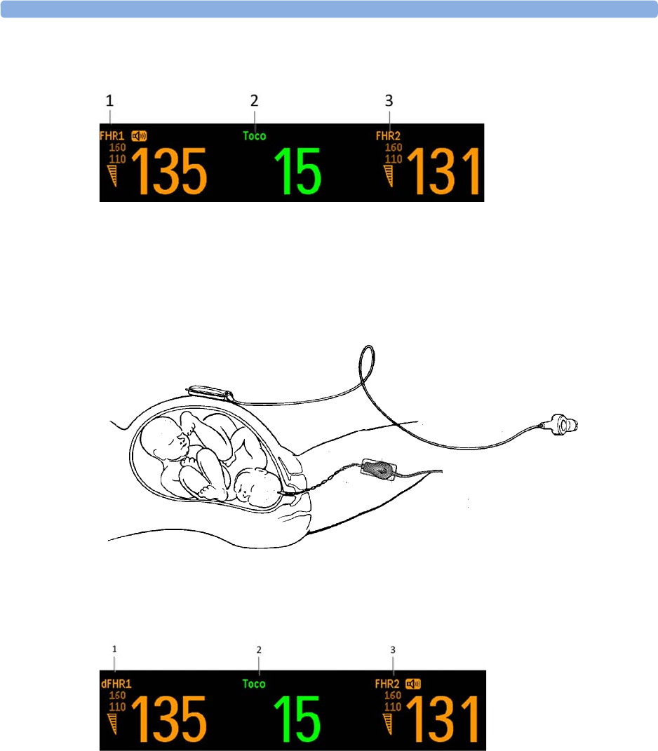
13 Monitoring Twin FHRs
185
Example of the screen showing ultrasound monitoring of twin FHRs:
Monitoring Twins Internally
FM30/50 Monitor one twin using the procedures described in “Monitoring FHR and FMP Using Ultrasound”
on page 165. Monitor the second twin using the procedures described in “Monitoring FHR Using
DECG” on page 199.
Example of a screen showing twin monitoring using a combination of US and DECG (the fetal heart
rate monitored via DECG is labeled "
dFHR1
"/"
dFHR2
"/"
dFHR3
" on the screen):
Separating FHR Traces
To help you to interpret traces with similar baselines, you can separate the baselines by an offset of
20 bpm by switching on trace separation. For details of the offset, see “Separation Order Type” on
page 186.
1FHR 1
2Toco parameter
3FHR 2
1dFHR 1
2Toco parameter
3FHR 2

13 Monitoring Twin FHRs
186
Switching Trace Separation On and Off
Connect transducers to the monitor to measure FHR. Depending on the measurement method, you
need either two ultrasound transducers or, for FM30/FM50, one ultrasound and one Toco+ transducer,
or one CL ECG/IUP transducer (to monitor DECG):
1Enter the
Main Setup
menu by pressing the
Main Setup
.
2Select
Fetal Recorder
.
3Select
Trace Separation
to switch between
On
and
Off
.
4Exit the
Main Setup
menu.
Separation Order Type
In Configuration Mode, you can choose between two methods,
Standard
and
Classic
, for dealing with
the trace offsets on the recording (the order in which they are separated) when
Trace Separation
is
On
.
•
Standard
: the FHR2 trace is shifted up by 20 bpm (it is recorded 20 bpm higher than it really is).
No offset is ever applied to the FHR1 trace - it stays where it is (a third FHR would be shifted
down by 20 bpm).
•
Classic
: the FHR1 trace is shifted up by 20 bpm when there is more than one FHR measurement.
No offset is ever applied to the FHR2 trace - it stays where it is (a third FHR would be shifted
down by 20 bpm).
When Trace Separation is On
When trace separation is turned on, the recorder prints a dotted line labeled with the two FHRs at the
top, and +20 at the bottom.
Examples of the two methods (
Standard
,
Classic
) for determining the trace separation order are
provided here.
"Standard" Separation Order
To make differentiating the traces easier, the trace from the ultrasound transducer connected to the
FHR2 channel is separated from that of FHR1 by 20 bpm. In other words, the trace for FHR2 is
recorded 20 bpm higher than it really is. The trace for FHR1 is never shifted.
The recorder prints a dotted line labeled +20 across the FHR scale, to identify the trace for FHR2. The
FHR trace is labeled +20 every 5 cm:
The label for FHR2 is annotated with a black filled +20:
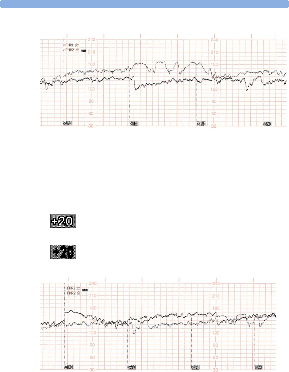
13 Monitoring Twin FHRs
187
The following trace shows trace separation switched on.
Only the FHR2 trace is offset. The numerical FHR value displayed on the monitor remains
unchanged. Subtract 20 from the recorded trace for FHR2 to obtain the true FHR2 value. For
example, if the recorded trace shows 160, then the true FHR is 140.
"Classic" Separation Order
To make differentiating the traces easier, the trace for FHR1 is offset by +20 bpm when FHR2 is
present. The FHR2 trace is never shifted.
The recorder prints a dotted line labeled+20 across the FHR scale, to identify the trace for FHR1. The
FHR trace is labeled +20 every 5 cm:
The label for FHR1 is annotated with a black filled +20:
The following trace shows trace separation switched on.
Only the FHR1 trace is shifted. The numerical FHR value displayed on the monitor remains
unchanged. Subtract 20 from the recorded trace for FHR1 to obtain the true FHR1 value. For
example, if the recorded trace shows 160, then the true FHR is 140.
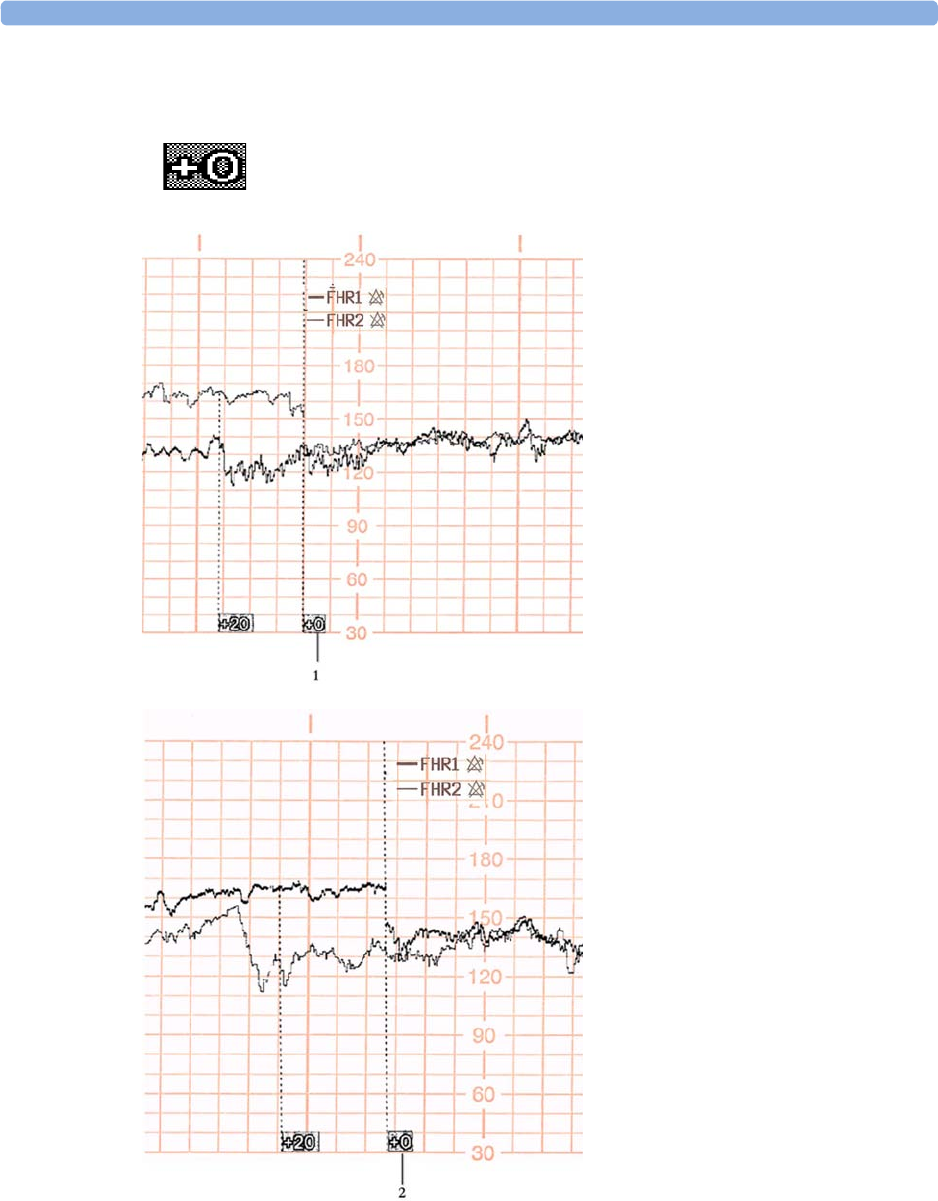
13 Monitoring Twin FHRs
188
When Trace Separation is Off
To indicate that trace separation is switched off, a dotted line labeled +0 prints across the FHR scale.
1
Standard
trace separation switched
off here
2
Classic
trace separation switched
off here

13 Monitoring Twin FHRs
189
Troubleshooting
Common problems that may occur when monitoring FHR using ultrasound are listed in “Monitoring
FHR and FMP Using Ultrasound” on page 165. See also “Monitoring FHR Using DECG” on
page 199 for common problems you might encounter when monitoring FHR directly.
The following problem may occur when monitoring twins.
For more information, see “Additional Information” on page 173.
Problem Possible Cause Solution
The question mark is
printed repeatedly, and
appears on the screen and
the INOP
Coincidence
is
issued.
Both transducers are recording the
same FHR, or one fetal transducer is
recording the maternal HR.
Reposition an ultrasound
transducer. See “Recommended
Actions for Coincidence INOP” on
page 164.

13 Monitoring Twin FHRs
190

14
191
14Monitoring Triple FHRs
If your monitor is equipped with the triplets option, it carries the label:
You can monitor triple FHRs externally using three ultrasound transducers. With the Avalon CL
Transducer system, you can monitor triplets with cableless transducers. The Avalon CTS system and
the CL F&M Pod do not have this option.
Refer to the appropriate preceding chapters for contraindications, and more information about the
available measurement methods.
FHR detection by the monitor may not always indicate that the fetuses are alive. Confirm fetal life
before monitoring, and continue to confirm that the fetuses are the signal source for the recorded fetal
heart rates. See “Confirm Fetal Life Before Using the Monitor” on page 10 and “Cross-Channel
Verification (CCV)” on page 159.
Important Considerations
• The procedures and any contraindications that apply for twins monitoring also apply for
monitoring triplets. In addition, when monitoring triplets: Be aware that monitoring three FHRs is
inherently more difficult than monitoring single or twin FHRs. The nature of the application
increases the likelihood that a fetal heart rate is monitored by more than one transducer.
• Ensure that you are recording three different fetal heart rates. Pay particular attention to any
coincidence of heart rates detected by the monitor's cross-channel verification feature.
• Fetal heart rate measurements are labeled in the order in which you plug in the transducers for
those measurements. It does not matter which fetal sensor socket you use, as the monitor allocates
a channel automatically. For instance, the first transducer you connect is automatically allocated a
channel, and the measurement is labeled
FHR1
, the second is labeled
FHR2
, and the third
FHR3
.
If you need to disconnect the transducers measuring the FHR temporarily, with the intention to
continue monitoring after the temporary break (for example, if the mother needs to go to the
bathroom), it is important that you reconnect the transducers in the same order as you originally
connected them to make sure that the measurement labels remain consistent.
Upon discharge of the patient all connected transducers are reset from left to right. Example: Only
one transducer is still connected to the monitor, it was labeled
FHR2
while monitoring the previous
discharged patient; it is now reset to
FHR1
.
14 Monitoring Triple FHRs
192
• The transducer finder LED lets you identify at a glance which transducer is monitoring which
heart rate channel.
• The fetal sensor socket to which a transducer is connected, is identified by the transducer position
indicator in the setup menu header:
• The trace recorded for the
FHR3
is thicker (darker) than that recorded for
FHR1
, which is thicker
than that for
FHR2
. This ensures that the three heart rates are easily distinguishable. The thickness
of the recorded trace can be changed in Configuration Mode.
• Remember that only one fetal heartbeat can be heard from the loudspeaker at a time. The audio
source symbol shows you which fetus you are listening to. To hear the other fetal heartbeat, select
the fetal heart rate sound for this channel (see “Selecting Fetal Heart Sound” on page 169).
• Monitor maternal pulse to avoid mistaking maternal heart rate for FHR.
• Ensure you are recording the best possible signals by referring to the signal quality indicators and
repositioning the transducers if necessary.
For the Avalon CL transducer system, see “Cableless Monitoring - Important Considerations” on
page 167.
Monitoring Triplets
To monitor triple FHRs, you need three ultrasound transducers. Follow the procedures described in
“Monitoring FHR and FMP Using Ultrasound” on page 165 and in “Monitoring Twin FHRs” on
page 183. The transducer finder LED lets you identify at a glance which transducer is monitoring
which heart rate channel.
Separating FHR Traces
To help you to interpret traces with similar baselines, you can separate the baselines by an offset of
20 bpm by switching on trace separation. For details of the offset, see “Separation Order Type” on
page 186.
FM20/FM30 FM40/FM50
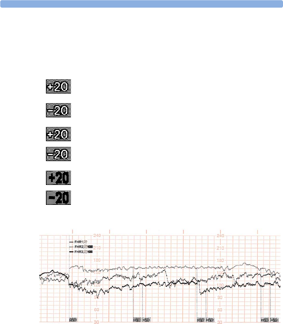
14 Monitoring Triple FHRs
193
"Standard" Separation Order
To make differentiating the traces easier, the trace for FHR2 is offset by +20 bpm, and the trace for
FHR3 is offset by -20 bpm. In other words, the trace for FHR2 is recorded 20 bpm higher than it
really is, while the trace for FHR3 is recorded 20 bpm lower than it really is. The trace for FHR1 is
never shifted.
The following trace shows triplets with
Trace Separation
on, and using
Standard
separation order.
The traces for FHR2 and FHR3 are offset. The numerical FHR values displayed on the monitor
remain unchanged. Subtract 20 from the recorded trace for FHR2 to obtain the true FHR2. For
example, if the recorded trace shows 160 bpm, then the true FHR is 140 bpm. Similarly, add 20 to the
recorded trace for FHR3 to obtain the true FHR3.
The recorder prints a dotted line labeled +20 across the FHR scale, to identify the
trace for FHR2.
The recorder prints a dotted line labeled -20 across the FHR scale, to identify the
trace for FHR3.
The FHR trace is labeled every 5 cm.
The label for FHR2 is annotated with +20 and the FHR3 label is annotated with
-20.
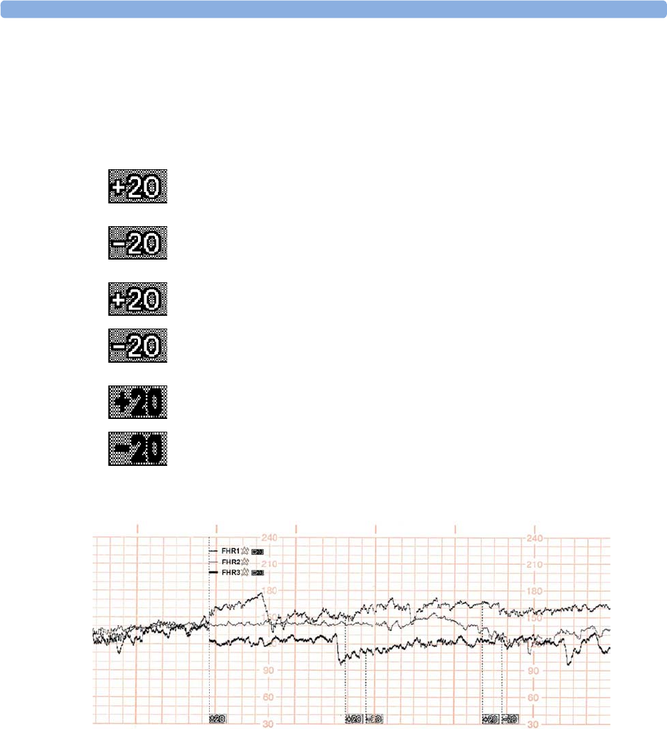
14 Monitoring Triple FHRs
194
"Classic" Separation Order
To make differentiating the traces easier, the trace for FHR1 is offset by +20 bpm when other FHR
measurements are present, and the trace for FHR3 is offset by -20 bpm. The FHR2 trace is never
shifted. In other words, the FHR traces are always sorted in ascending order from top to bottom.
The following trace shows triplets with
Trace Separation
on, and using
Classic
separation order.
The traces for FHR1 and FHR3 are shifted. The numerical FHR values displayed on the monitor
remain unchanged. Subtract 20 from the recorded trace for FHR1 to obtain the true FHR1. For
example, if the recorded trace shows 160 bpm, then the true FHR is 140 bpm. Similarly, add 20 to the
recorded trace for FHR3 to obtain the true FHR3.
The recorder prints a dotted line labeled +20 across the FHR scale, to identify the
trace for FHR1.
The recorder prints a dotted line labeled -20 across the FHR scale, to identify the
trace for FHR3.
The FHR trace is labeled every 5 cm.
The label for FHR1 is annotated with +20 and the FHR3 label is annotated with
-20.
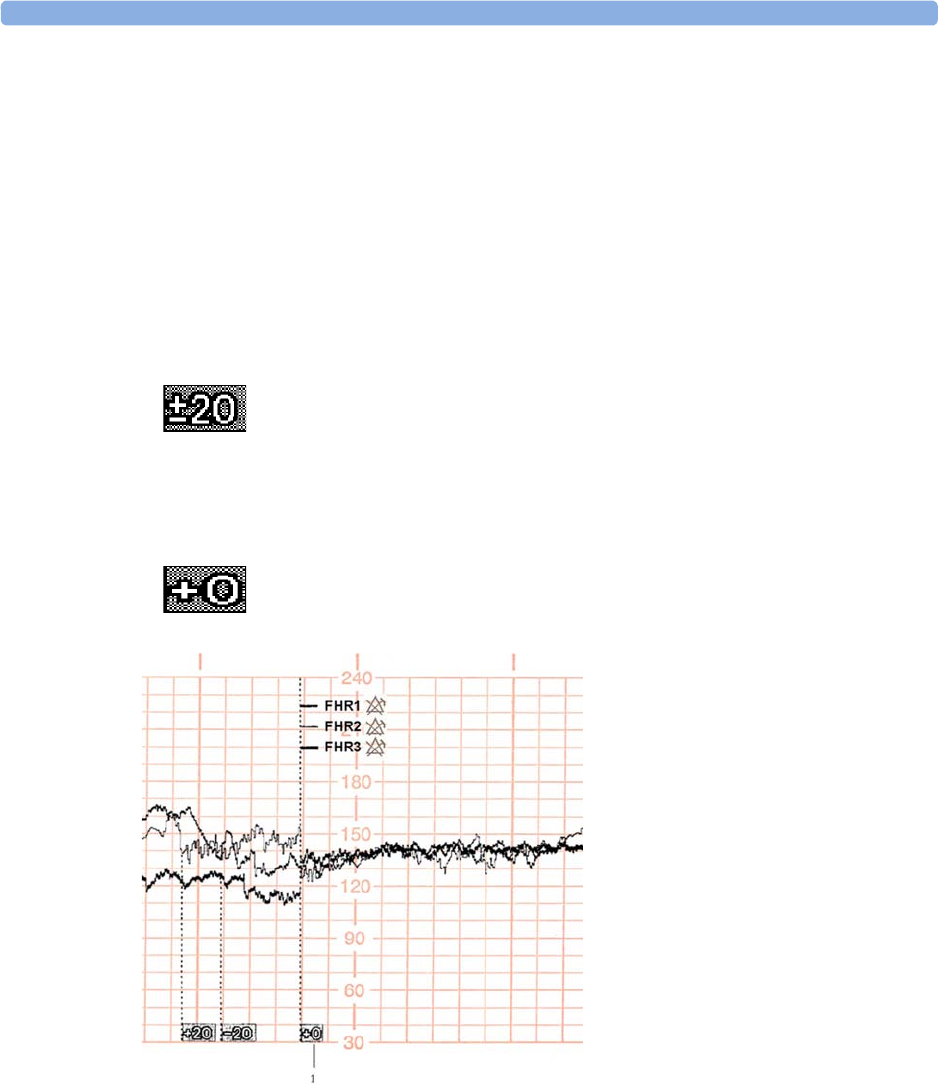
14 Monitoring Triple FHRs
195
Switching Trace Separation On and Off
1Connect three ultrasound transducers to the monitor to measure FHR.
2See “Switching Trace Separation On and Off” on page 186 for details of how to switch trace
separation on or off.
When Trace Separation is On
When trace separation is turned on, the recorder prints a dotted line labeled with the three FHRs at the
top, and ±20 at the bottom. Examples of the two methods (
Standard
,
Classic
) for determining the trace
separation order are provided here.
When Trace Separation is Off
To indicate that trace separation is switched off, a dotted line labeled +0 prints across the FHR scale.
1
Standard
trace separation switched
off here
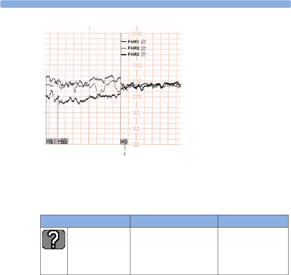
14 Monitoring Triple FHRs
196
Troubleshooting
Common problems that may occur when monitoring FHR using ultrasound are listed in “Monitoring
FHR and FMP Using Ultrasound” on page 165.
The following problem may occur when monitoring triplets.
For more information, see “Additional Information” on page 173.
2
Classic
trace separation switched
off here
Problem Possible Cause Solution
The question mark is
printed repeatedly, and
appears on the screen
and the INOP
Coincidence
is issued.
More than one transducer is
recording the same FHR, or a fetal
transducer records the same heart
rate as the maternal HR.
Reposition one or more
ultrasound transducer, as
appropriate. See
“Recommended Actions
for Coincidence INOP” on
page 164

15
197
15Fetal Heart Rate Alarms
Fetal heart rate (FHR) alarms can give both audible and visual warning of a non-reassuring fetal
condition. Your monitor must be configured to alarm mode
All
to enable the FHR alarms (see
“Alarms” on page 117).
Changing Alarm Settings
When you do any of the following actions for any FHR measurement channel, this applies for all active
FHR measurements, ultrasound, DECG, and aFHR:
• Turning FHR alarms on or off
• Changing alarm limits
• Changing alarm delays
• Changing signal loss delay
The monitor retains these settings, even when switched off. The alarm limits are printed on the trace
every few pages if alarms are on.
Turning Alarms On or Off
1Connect either an ultrasound or a DECG transducer to a free socket on the monitor, or use the
CL F&M Pod.
2Enter the setup menu for a connected FHR measurement.
3Select
Alarms
to switch between
On
and
Off
.
Changing Alarm Limits
1Connect either an ultrasound or a DECG transducer to a free socket on the monitor, or use the
CL F&M Pod.
2Enter the setup menu for a connected FHR measurement.
3To change the high alarm limit, select
High Limit
and select the alarm limit from the pop-up list.
4To change the low alarm limit, select
Low Limit
and select the alarm limit from the pop-up list.

15 Fetal Heart Rate Alarms
198
Changing Alarm Delays
You can change the alarm delays if the
Alarm Mode
is set to
All
.
1Connect either an ultrasound or a DECG transducer to a free socket on the monitor, or use the
CL F&M Pod.
2Enter the setup menu for a connected FHR measurement.
3To change the high alarm limit delay time, select
High Delay
and select the delay time (in seconds)
from the pop-up list.
4To change the low alarm limit delay time in seconds, select
Low Delay
and select the delay time (in
seconds) from the pop-up list.
Changing Signal Loss Delay
The signal loss delay is the configurable delay before a
Signal Loss
INOP is issued. You can change the
delay:
1Connect either an ultrasound or a DECG transducer to a free socket on the monitor, or use the
CL F&M Pod.
2Enter the setup menu for a connected FHR measurement.
3Select
SignalLoss Delay
and select the signal loss INOP delay time (in seconds) from the pop-up
list.

16
199
16Monitoring FHR Using DECG
FM30/50 This chapter describes how to monitor a single fetal heart rate via direct ECG (DECG), using a spiral
fetal scalp electrode in the intrapartum period.
Read and adhere to the instructions that accompany the fetal scalp electrode, the DECG
adapter cable, and the attachment electrode. Pay attention to all the contraindications,
warnings, and for the DECG adapter cable, the cleaning and disinfection procedures.
Before starting to monitor, first define the fetal position, and ensure that it is suitable for DECG
monitoring.
Misidentification of Maternal HR as FHR
Confirm fetal life before monitoring, and continue to confirm that the fetus is the signal source for the
FHR during monitoring. Here are two examples where the maternal HR can be misidentified as the
FHR when using a fetal scalp electrode:
• Electrical impulses from the maternal heart can sometimes be transmitted to the fetal monitor
through a recently deceased fetus via the spiral scalp electrode, appearing to be a fetal signal
source.
• The recorded maternal HR, and any artifact, can be misinterpreted as an FHR especially when it is
over 100 bpm.
To reduce the possibility of mistaking the maternal HR for FHR, monitor both maternal and fetal
heart rates (see “Monitoring Maternal Heart / Pulse Rate” on page 221). The monitor's cross-channel
verification (CCV) facility can help by automatically detecting when the same heart rate is being
recorded by different transducers. See “Confirm Fetal Life Before Using the Monitor” on page 10 and
“Cross-Channel Verification (CCV)” on page 159.
If the
Coincidence
INOP is issued at the fetal monitor if you are measuring FHR with DECG:
1Confirm that the scalp electrode is placed correctly.
2Confirm fetal life by palpation of fetal movement or auscultation of fetal heart sounds using a
fetoscope, stethoscope, or Pinard stethoscope.
3If you cannot hear the fetal heart sounds, and you cannot confirm fetal movement by palpation,
confirm fetal life using obstetric ultrasonography.
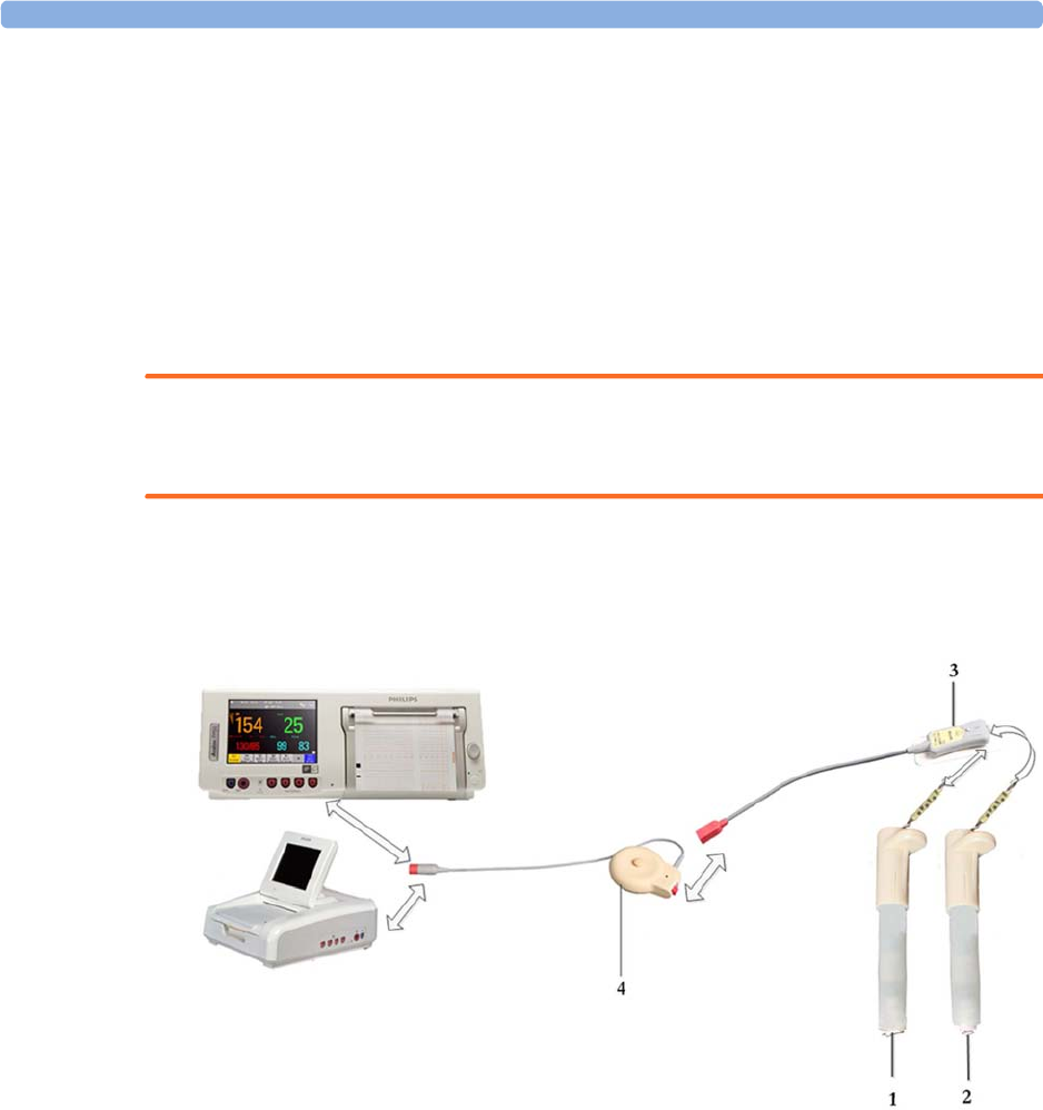
16 Monitoring FHR Using DECG
200
4In case of difficulties deriving a stable maternal pulse reading using the Toco MP or CL Toco+ MP
transducer, use SpO2 instead. In case of similar problems with the pulse measurement from SpO2,
use MECG instead. Reasons to switch the method for deriving a maternal pulse or heart rate
include: motion artifacts, arrhythmia, and individual differences in pulse signal quality on the
abdominal skin (via Toco+ MP).
What You Need
You can measure fetal DECG using the equipment combinations shown in the following figures.
WARNING
Never attempt to connect the fetal scalp electrode to anything other than the correct DECG adapter
cable.
DECG with Toco+
The figure below shows the complete connection chain from the fetal scalp electrode to the fetal
monitor using the Toco+ transducer.
1Fetal Scalp Electrode, single spiral (989803137631)
2Fetal Scalp Electrode, double spiral, Europe only, not for USA (989803137641)
3DECG Adapter Cable (9898 031 37651) with Pre-gelled Attachment Electrode (989803139771)
4Toco+ transducer (M2735A)
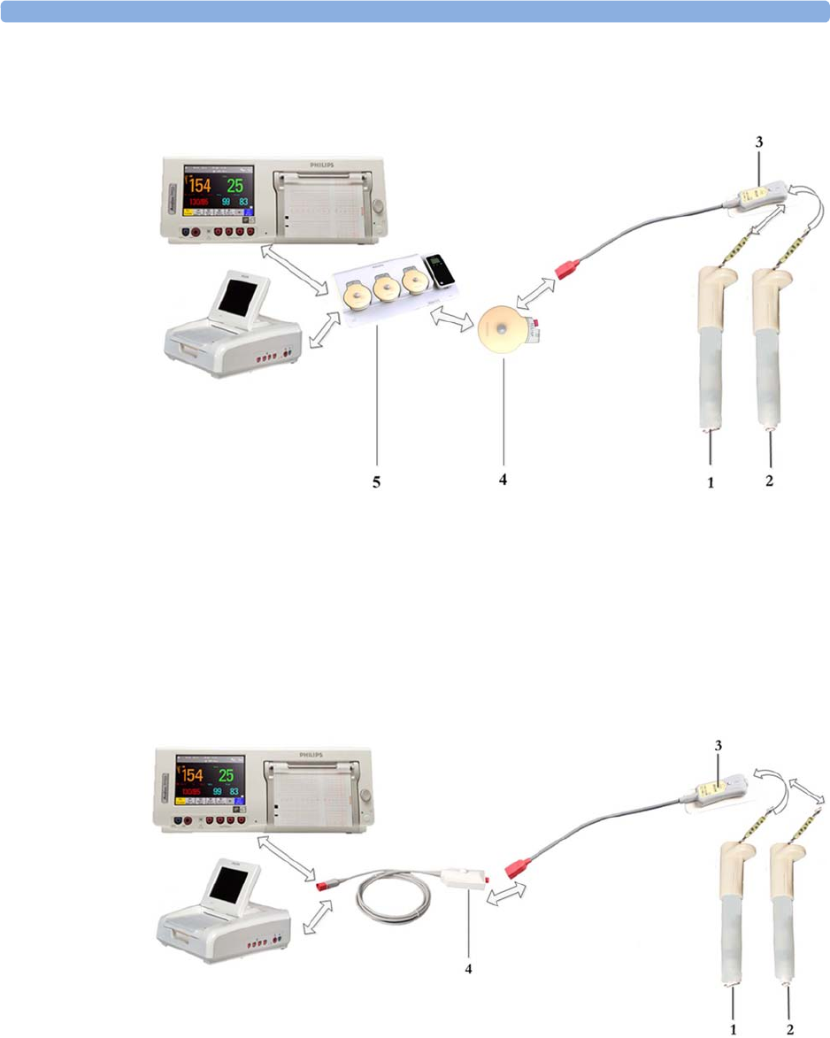
16 Monitoring FHR Using DECG
201
DECG with CL Toco+MP or CL ECG/IUP
The figure below shows the equivalent chain using the CL Toco+ MP or CL ECG/IUP transducer.
1Fetal Scalp Electrode, single spiral (989803137631)
2Fetal Scalp Electrode, double spiral, Europe only, not for USA (989803137641)
3DECG Adapter Cable (9898 031 37651) with Pre-gelled Attachment Electrode (989803139771)
4CL Toco+ MP (866075) or CL ECG/IUP transducer (866077)
5Avalon CL base station (866074)
DECG with Patient Module
The figure below shows the equivalent chain using the patient module.
1Fetal Scalp Electrode, single spiral, (989803137631)
2Fetal Scalp Electrode, double spiral, Europe only, not for USA (989803137641)
3DECG Adapter Cable (9898 031 37651) with Pre-gelled Attachment Electrode (989803139771)
4Patient Module (M2738A)

16 Monitoring FHR Using DECG
202
Making Connections
WARNING
Follow the instructions supplied with each of the monitoring accessories you are using.
Prepare for DECG monitoring using the list below. The standard procedures in use in your facility
determine the sequence of actions.
1If you change the monitoring mode from US to DECG, first disconnect the US transducer.
2Depending on the equipment you are using, ensure that the Toco+ transducer, CL Toco+ MP, the
CL ECG/IUP transducer, or the patient module is connected to the fetal monitor.
3Attach the fetal scalp electrode to the fetus, following the instructions supplied with the fetal scalp
electrode.
4Attach a pre-gelled attachment electrode to the DECG adapter cable, following the instructions
supplied with the DECG adapter cable.
5Fix the attachment electrode to the mother's thigh, following the instructions supplied with the
attachment electrode.
Depending on the equipment you are using, connect the red connector plug on the DECG
adapter cable to the red connector on the Toco+ transducer, CL Toco+ MP, the CL ECG/IUP
transducer, or the patient module.
6Connect the fetal scalp electrode to the DECG adapter cable.
You are now ready to begin monitoring DECG.
WARNING
The fetal/maternal monitor is not a diagnostic ECG device. In particular, the display of fetal/maternal
ECG is intended only for evaluating signal quality for fetal/maternal heart rate as derived from the
ECG waveform.
When in doubt, it can be used to identify sources of compromised signal quality, such as noise or
muscle artifacts. It can subsequently be used to verify the result of measures taken to resolve them (e.g.
checking ECG cable connections or adapting the fetal
ArtifactSuppress
configuration).
The safety and effectiveness of the displayed fetal/maternal ECG waveform (i.e. P, QRS, and T
segments) for evaluation of fetal/maternal cardiac status during labor have not been evaluated.
Monitoring DECG
To simultaneously measure DECG and MECG, you need the CL ECG/IUP transducer or the patient
module for DECG, and a Toco+, CL Toco+ MP, or CL ECG/IUP transducer for MECG (see
“Monitoring Maternal Heart / Pulse Rate” on page 221). Alternatively, you can monitor the maternal
pulse rate via pulse oximetry (see “Pulse Rate from SpO2” on page 228). You can also monitor
maternal pulse with the Toco MP or CL Toco+ MP transducer. In any case where you would use a
Toco+ or Toco MP transducer, you can also monitor with a CL Toco+ MP transducer.
1Switch on the recorder.
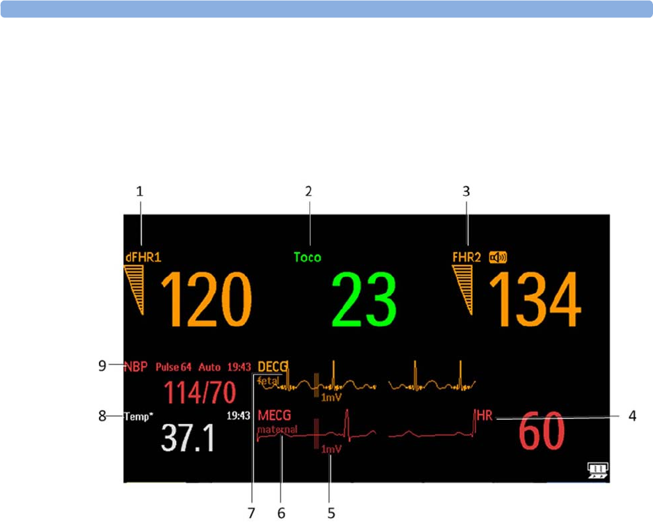
16 Monitoring FHR Using DECG
203
2The heart rate monitored via DECG is labeled
dFHR1
/
dFHR2
/
dFHR3
on the screen. If
configured, the DECG wave is displayed automatically on the screen, labeled
DECG
, and
fetal
. If
MECG is being monitored, both waves are displayed, with the DECG wave above the MECG
wave. The MECG wave is labeled
MECG
and
maternal
.
3Check the artifact suppression setting and change it if necessary (see “Suppressing Artifacts” on
page 204).
NOTE
The 1mV scale bar for the DECG and MECG wave is not displayed on the screen if you monitor
DECG or MECG with an Avalon CTS system. The Avalon CTS system does not provide a scaled
ECG.
1Measurement label (dFHR1)
2Measurement label (Toco)
3Measurement label (FHR2)
4Measurement label (HR)
51mV scale bar
6MECG wave with maternal label
7DECG wave with fetal label
8Measurement label (Temp) maternal temperature
9Measurement label NBP

16 Monitoring FHR Using DECG
204
WARNING
Periodically compare the mother's pulse with the signal coming from the monitor's loudspeaker to
ensure that you are monitoring fetal heart rate. If the maternal HR coincides with the FHR, do not
misinterpret the maternal HR as the FHR (see also “Confirm Fetal Life Before Using the Monitor” on
page 10 and “Cross-Channel Verification (CCV)” on page 159.
Suppressing Artifacts
When the monitor's artifact suppression is on, instantaneous heart rate changes of 28 bpm or more,
however caused, are not recorded. Fetal arrhythmia will also be suppressed. If you suspect fetal
arrhythmia, switch artifact suppression off. When artifact suppression is off, all recorded fetal
heartbeats within the specified range are shown. The default setting is
On
(artifacts are suppressed).
To change the setting:
1Enter the
Setup dFHR1
menu.
2Select
ArtifactSuppress
to switch between artifact suppression
On
(artifacts are suppressed) and
Off
(no artifact suppression, use this setting if you suspect fetal arrhythmia).
When artifact suppression is off,
Artifact Suppression Off
is annotated on the trace recording.
Printing the Waveform
You can print the DECG wave onto the trace paper. Refer to “Printing the ECG Waveform” on
page 231.

16 Monitoring FHR Using DECG
205
Troubleshooting
NOTE
In many cases you need to see the DECG wave to check if the signal quality is good enough to derive
a valid fetal heart rate. In the dFHR setup menu, switch on the display of the DECG wave.
Testing DECG Mode
See the monitor's Service Guide.
Problem Possible Cause Solutions
dFHR1 Equip Malf
dFHR2 Equip Malf
dFHR3 Equip Malf
Malfunctioning equipment See “Patient Alarms and INOPs” on
page 129.
dFHR1 Leads Off
dFHR2 Leads Off
dFHR3 Leads Off
Numeric is displayed with a -?-;
INOP tone
See also “Patient Alarms and
INOPs” on page 129.
Erratic trace
Erratic display
Fetal scalp electrode detached at
connector
Reconnect the fetal scalp electrode
If the wave is configured to be displayed
on the monitor, you can observe if the
ECG signal is clear, or if it shows
interruptions and noise
Poor or no contact between leg
attachment electrode and mother
Check all connections
Disconnect and reconnect the connector
several times
No contact between the DECG adapter
cable and the leg attachment electrode
No contact between the fetal scalp
electrode connector and the DECG
adapter cable
Check all connections
Disconnect and reconnect the connector
several times
If problem persists, use a new fetal scalp
electrode
No ECG signal
Poor contact between the reference
electrode and the mother
Check for fetal demise
Use a new fetal scalp electrode if
necessary
Signal quality indicator
continuously shows a poor signal
Fetal arrhythmia Use a new fetal scalp electrode if
necessary
dFHR1 Signal Loss
dFHR2 Signal Loss
dFHR3 Signal Loss
No signal See “Patient Alarms and INOPs” on
page 129.
dFHR1 Unplugged
dFHR2 Unplugged
dFHR3 Unplugged
No connection See “Patient Alarms and INOPs” on
page 129.

16 Monitoring FHR Using DECG
206
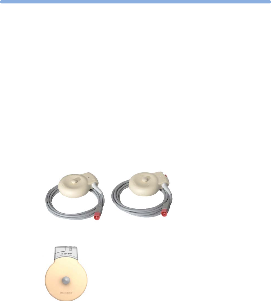
17
207
17Monitoring Uterine Activity
Externally
You can measure uterine activity externally using a Toco transducer. You can also use a Toco+,
Toco MP, or a CL Toco+ MP transducer for the same purpose, although they also have more (ECG/
IUP and Pulse) capabilities.
The external Toco transducer allows to monitor the frequency, duration, and relative strength of
contractions, but not their absolute intensity. Amplitude and sensitivity depend on various factors such
as the position of the transducer, the belt tension, and the size of the patient.
What You Need
Toco, Toco MP, or Toco+ transducer
CL Toco+ MP transducers (additionally capable of providing the
maternal pulse measurement)
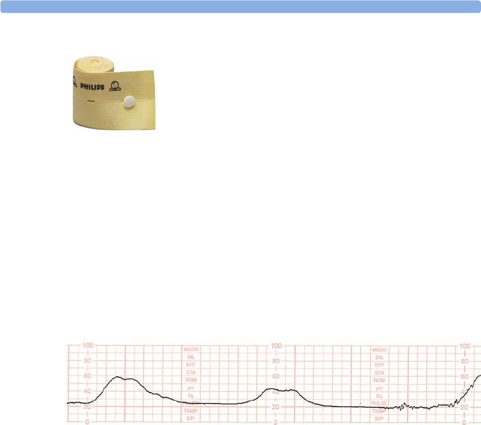
17 Monitoring Uterine Activity Externally
208
External Toco Monitoring
Prepare for Toco monitoring using the list below. The standard procedures in use in your facility
determine the sequence of actions.
1Fasten the abdominal transducer belt around the patient.
2Connect the Toco transducer to a free socket on the monitor. The Toco baseline is automatically
reset. The Toco display shows 20. "
Toco
", indicating external uterine measurement, is printed on
the trace at intervals.
3Place the transducer on the patient's fundus to ensure the optimum recording of uterine activity.
4Reset the Toco baseline as necessary (see “Resetting the Toco Baseline” on page 208), but not
during a contraction.
The following example trace shows two contractions.
Resetting the Toco Baseline
1Press the
Toco Baseline
SmartKey. This resets the Toco baseline to 20 on the display and trace.
2If the Toco value is negative for more that five seconds, the Toco baseline is automatically reset to
0 units.
Toco Sensitivity
If the Toco sensitivity is too high, and the Toco trace exceeds the paper scale, you can reduce the Toco
sensitivity to 50%. The default setting is 100%.
To change the Toco sensitivity:
1Enter the
Setup Toco
menu.
2Select
Gain
to switch between
100%
and
50%
.
Troubleshooting
Abdominal Belt (disposable shown)

17 Monitoring Uterine Activity Externally
209
External Toco Monitoring
Problem Possible Causes Solutions
Quality of the trace deteriorates
or the Toco baseline varies
The belt is incorrectly fastened and is
too slack or too tight, or the belt has lost
its elasticity.
The belt must be tight enough to ensure
good contact between the patient's skin
and the entire surface of the transducer
without causing discomfort. Ensure you
are using the correct belt. Adjust it as
necessary.
Fetal movement Check if the belt is correctly fastened
and adjust it as necessary. Reposition the
transducer and reset the Toco baseline if
necessary.
Maternal respiration superimposed on
trace
Check if belt is not too loose.
Maternal movement/change of position Following maternal movement, reset
Toco baseline
Toco sensitivity is too high
(above 100 units)
Toco trace is exceeding the paper
scale
Physical transmission of pressure from
the uterus to the sensor is much higher
than the average value.
Check if the belt is too tightly fastened.
Select 50% Toco sensitivity.
Toco Equip Malf
is displayed. See “Patient Alarms and INOPs” on
page 129.
Toco Unplugged
is displayed. See “Patient Alarms and INOPs” on
page 129.
If you suspect the signal from the transducer. Test the Transducer (see “Testing Toco
Transducers” on page 210 below).

17 Monitoring Uterine Activity Externally
210
Testing Toco Transducers
If any of the following tests fail, repeat the test using another transducer. If the second transducer
passes the tests, confirming that the first transducer is defective, contact your service personnel.
If the second transducer also fails the tests, contact your service personnel.
You can test all Toco transducers, including the cableless ones, as described above.
To test a Toco transducer:
1Switch on the monitor and the
recorder.
2Connect the transducer to the fetal
monitor.
3Gently apply pressure to the pick-
up button.
4Check if after a few seconds the
values on the display and paper
show this change in pressure.
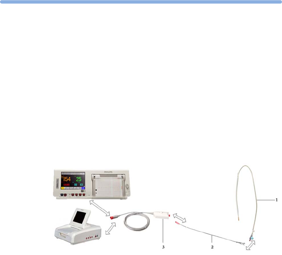
18
211
18Monitoring Uterine Activity
Internally
FM30/50 You can monitor intrauterine pressure (IUP) using an intrauterine catheter together with a patient
module, Toco+, or the CL ECG/IUP or CL Toco+ MP transducer, after rupture of the membranes
and the cervix is sufficiently dilated.
What You Need
IUP with Patient Module
The figure below shows the complete connection chain from the IUP catheter to the fetal monitor
using the patient module:
1Disposable Koala IUP Catheter (M1333A)
2Reusable Koala IUP Adapter Cable (9898 031 43931)
3Patient Module (M2738A)
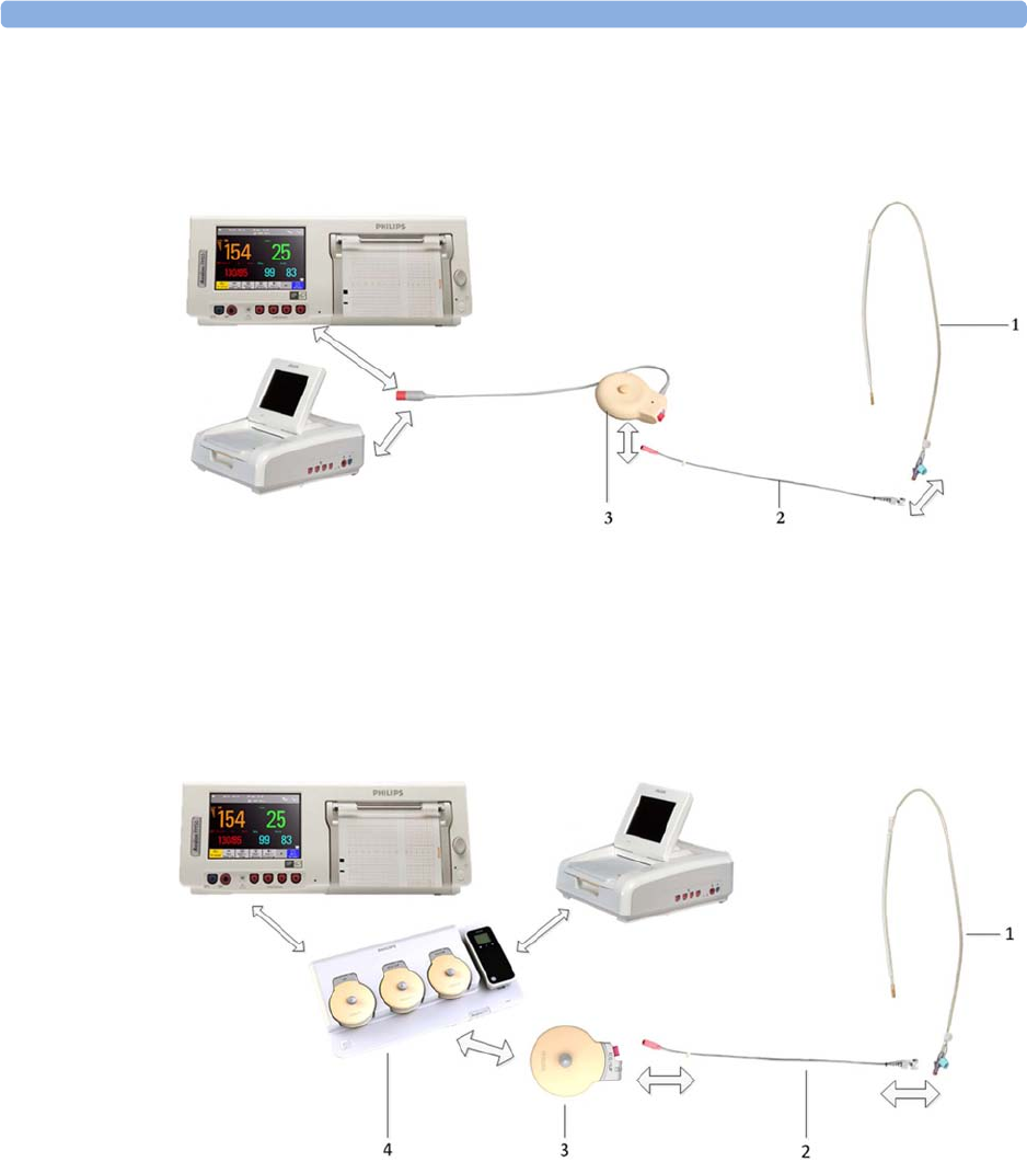
18 Monitoring Uterine Activity Internally
212
IUP with Toco+
The figure below shows the complete connection chain from the IUP catheter to the fetal monitor
using the Toco+ transducer:
1Disposable Koala IUP Catheter (M1333A)
2Reusable Koala IUP Adapter Cable (9898 031 43931)
3Toco+ transducer (M2735A)
IUP with CL ECG/IUP
The figure below shows the complete connection chain from the IUP catheter to the fetal monitor
using the CL ECG/IUP transducer:
1Disposable Koala IUP Catheter (M1333A)
2Reusable Koala IUP Adapter Cable (9898 031 43931)
3CL ECG/IUP or CL Toco+ MP transducer (866077)
4Avalon CL base station (866074)

18 Monitoring Uterine Activity Internally
213
Internal (IUP) Monitoring
Read the instructions that accompany the intrauterine catheter and the adapter cable before you start
monitoring. Zero the IUP measurement when instructed.
WARNING
Do not catheterize if placenta previa is diagnosed, or if uterine bleeding from an undetermined source
is present.
Prepare for IUP monitoring using the list below. The standard procedures in use in your facility
determine the sequence of actions.
1Perform a complete clinical evaluation.
2Catheterize after membrane rupture. Insert the catheter according to its accompanying
instructions.
3Connect the catheter to the socket on the patient module.
4Connect the patient module to a free socket on the monitor. The monitor is automatically zeroed.
The IUP display shows 0.
IUP
, indicating internal measurement is printed at intervals on the trace.
5Zero the IUP measurement (see “Zero The IUP Measurement” on page 213).
6If you suspect the catheter is not responding appropriately, flush as directed in the catheter's
Instructions for Use. A pressure spike appears on the trace if you flush after connecting the
transducer to the monitor.
Zero The IUP Measurement
Zero the IUP measurement by selecting the
Zero IUP
SmartKey, or selecting
Zero IUP
in the
Setup IUP
menu. This resets the display and trace to 0. If you do not zero the monitor properly, the pressure trace
may exceed the paper scaling.
Selecting the IUP Unit
You can select between mmHg (default) and kPa for the IUP unit.
1Enter the
Setup IUP
menu.
2Press
Unit
to switch between
mmHg
and
kPa
.

18 Monitoring Uterine Activity Internally
214
Troubleshooting
Internal (IUP) Monitoring
Problem Possible Causes Solutions
Only pressure peaks can be seen
(baseline not visible).
Zero adjustment is incorrect. Zero the IUP measurement.
No change in pressure during
contraction.
Catheter tip not in contact with
amniotic fluid or possible extra-ovular
placement of the catheter.
Refer to catheter Instructions for
Use.
Trace is a straight line. Connection issue or cable or catheter
defective.
• Unplug/replug catheter
• Unplug/replug or exchange
adapter cable
• Try new catheter
Trace is superimposed with noise. Possible extra-ovular placement of
catheter.
Refer to catheter Instructions for
Use.
IUP Equip Malf
INOP is displayed. See “Patient Alarms and INOPs” on page 129.
IUP Unplugged
INOP is displayed.

19
215
19Monitoring aFHR, aHR, and
aToco
Introducing the abdominal Avalon CL Fetal & Maternal Pod Measurement
The Avalon CL Fetal & Maternal Pod (CL F&M Pod) noninvasively measures fetal heart rate (aFHR),
maternal heart rate (aHR), and uterine activity (aToco). The CL F&M Pod is used together with a
single-use electrode patch. The electrode patch has five adhesive electrodes. The CL F&M Pod and
electrode patch are placed on the maternal abdomen. It picks up the fetal and maternal
electrocardiography (ECG) signals, and the uterine electromyography (EMG) signals. The CL F&M
Pod separates and processes the signals, and transmits aFHR, aHR, and aToco to the fetal monitor via
the CL base station.
CAUTION
Use the CL F&M Pod and electrode patch with singleton pregnancies only. The measurements have
been validated with a gestational age of >36 weeks.
NOTE
• Fetal ECG and uterine EMG signals are very small. Therefore, skin preparation is required when
applying the electrodes.
• Different measurements for the same physiological parameter may have a different appearance on
the trace, due to variability (HR), averaging, delay, amplitude, or artifacts.
• The beat-to-beat variability of aFHR may appear lower than FHR from ultrasound and lower than
dFHR from DECG due to averaging. The accuracy of all FHR parameters is sufficient for
diagnosis following commonly agreed guidelines.
Fetal Heart Rate aFHR
It is recommended to verify the presence of the fetal heart beat, for example with a stethoscope, before
starting continuous monitoring with the CL F&M Pod.

19 Monitoring aFHR, aHR, and aToco
216
CAUTION
If the aFHR signal quality indicator on the fetal monitor screen continuously indicates an insufficient
signal quality (empty triangle), although the CL F&M electrode status is green, then an alternative
method to monitor should be used.
Uterine Activity aToco
The CL F&M Pod measures the electrical activity of the uterus which is different to the mechanical
measurements of a Toco transducer or an IUP catheter. Depending on the measurement method, the
shape of a recorded contraction can look different. The uterine EMG signals can be interfered with by
the electrical activity of other muscles, for example during maternal or fetal movements or position
changes.
CAUTION
The aToco measurement does not represent the absolute intrauterine pressure. If aToco seems
questionable, verify uterine activity by other means (maternal perception, manual palpation, or
intrauterine pressure (IUP) measurement). For monitoring the real intrauterine pressure in mmHg or
kPa, an IUP catheter is required.
CAUTION
The duration of the contraction measured by the CL F&M Pod can be shorter than the physical
contractions. When you palpate the uterus, there is a delay between the manual detection of
contraction, and when it is displayed at the monitor.
CAUTION
Maternal or fetal movements can cause electrical signals that may result in intrauterine contraction-like
artifacts.
Maternal movement
When consistent maternal movement is detected:
• A question mark is displayed in front of the aToco numeric at the monitor (?aToco).
• The aToco trace is printed with a lighter intensity for the duration of the maternal movements,
indicating that the signal may be compromised and not suitable for trace interpretation.
Uterine Activity Measurement Priority
When several uterine activity measurements are active, the priority given on the monitor display is:
• IUP (Intrauterine pressure from the connection with an IUP catheter)
•aToco (CL F&M Pod)
•Toco (CL Toco
+MP transducer, Toco+ or Toco MP wired transducer)

19 Monitoring aFHR, aHR, and aToco
217
aToco Sensitivity
Monitoring with the CL F&M Pod, the aToco sensitivity can be set to
High
or
Low
at any time. The
Low
sensitivity setting provides an additional suppression of artifacts, for example artifacts coming
from maternal and fetal movements. The additional filtering delays the onset of recording the
contraction on the trace and shows a reduced amplitude.
The default setting is
High
and recommended for active labor.
Setting the aToco Sensitivity
1Select the
Setup aToco
menu.
2Select the
Sensitivity
by toggling between
High
and
Low
.
What You Need
• For monitoring with the CL F&M Pod, see “Avalon CL Fetal & Maternal Pod” on page 21 and
“CL Fetal & Maternal Electrode Patch” on page 91.
• For assigning the CL F&M Pod, see “CL Pod Assignment” on page 99.
• For applying the electrode patch and the CL F&M Pod, see “Applying the CL Fetal & Maternal
Patch and Pod” on page 100.
At the Monitor
1Switch on the recorder.
2The fetal heart rate is labeled
aFHR1
,
aFHR2
, or
aFHR3
on the screen. The CL F&M Pod monitors
only singletons, but if in addition to
aFHR
a CL US transducer and/or a scalp electrode (DECG)
are used to monitor FHR, the aFHR numeric is labeled 1 to 3 depending on the sequence in which
the other measurement methods are added.
3aFHR and aHR have a QRS tone. The volume can be set in the measurement's setup menu, see
“Selecting Fetal Heart Sound” on page 169.
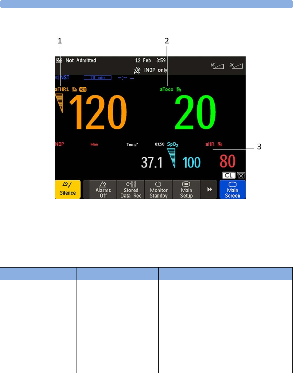
19 Monitoring aFHR, aHR, and aToco
218
Troubleshooting
1Measurement label aFHR
2Measurement label aToco
3Measurement label aHR
Problem Possible Causes Solutions
Erratic trace
Erratic display
Fetal arrhythmia Consider monitoring FHR with alternative methods.
Electrode contact not optimal Reposition the electrode and repeat the skin
preparation until the CL F&M Status shows that all
electrodes have good contact.
Obese patient If a patient is obese, re-position the lower electrode
on the midline 1-2 in/3-5 cm below the original
placement, or on the underside of the panniculus just
below the turn.
Too much maternal or fetal
movement
Ask the patient to sit or lie still until the signal
improves. If the signal indication does not improve,
consider monitoring with alternative methods.

19 Monitoring aFHR, aHR, and aToco
219
NOTE
For all signal loss, malfunction, or other alerts see “Patient Alarms and INOPs” on page 129.
Signal quality indicator is
continuously poor
Electrode contact not optimal Repeat the skin preparation until the CL F&M Status
shows that all electrodes have good contact.
Patient in unfavorable position Make the patient more comfortable, if the abdominal
muscles are relaxed it may improve the signal. For
example, place a pillow to support the patient’s back.
If the signal indication does not improve, consider
monitoring with alternative methods.
Mobile abdomen If the abdomen is mobile, or patient position has
changed, use a rolled blanket/towel or pillow to
support abdomen to keep the patch centered on the
uterus. If the signal indication does not improve,
consider monitoring with alternative methods.
aFHR not recorded or
questionable
aFHR is less than 60 bpm or
over 240 bpm, fetal demise,
fetal arrhythmia, or the baby is
born
Verify the FHR by independent means.
Problem Possible Causes Solutions

19 Monitoring aFHR, aHR, and aToco
220

20
221
20Monitoring Maternal Heart /
Pulse Rate
You can monitor the maternal heart/pulse rate using one of five sources:
• Maternal heart rate (HR) via MECG electrodes
• Maternal heart rate (aHR) via CL F&M Pod
• Maternal pulse rate from Toco MP or CL Toco+ MP transducer (Pulse)
• Maternal pulse rate from SpO2 (Pulse)
• Maternal pulse rate from NBP (Pulse)
Maternal heart/pulse rates derived from Toco MP or CL Toco+ MP, SpO2, aHR, and MECG are
continuous measurements, and are compared against the FHR for cross-channel verification. Average
pulse rate derived from noninvasive blood pressure is an intermittent measurement, and is therefore
not used for cross-channel verification.
Priority for Maternal Heart / Pulse Rate
Only one maternal heart rate/pulse rate numeric is displayed and recorded at a time (see priority table).
If higher-priority measurements are connected but temporarily not providing valid numerics, lower-
priority numerics may be displayed and recorded instead.
Priority Maternal Heart / Pulse Rate
Source
Alarming Used for CCV Provides QRS
Tone
1 HR from MECG measurement Yes Yes Yes
2 aHR from CL F&M Pod Yes Yes Yes
3 Pulse from CL SpO2 Pod
measurement
Yes Yes No
4 Pulse from SpO2 measurement Yes Yes Yes
5 Pulse from Toco MP measurement
cableless or cabled
No Yes No
6 Pulse from CL NBP Pod
measurement
No No No
7 Pulse from NBP measurement No No No
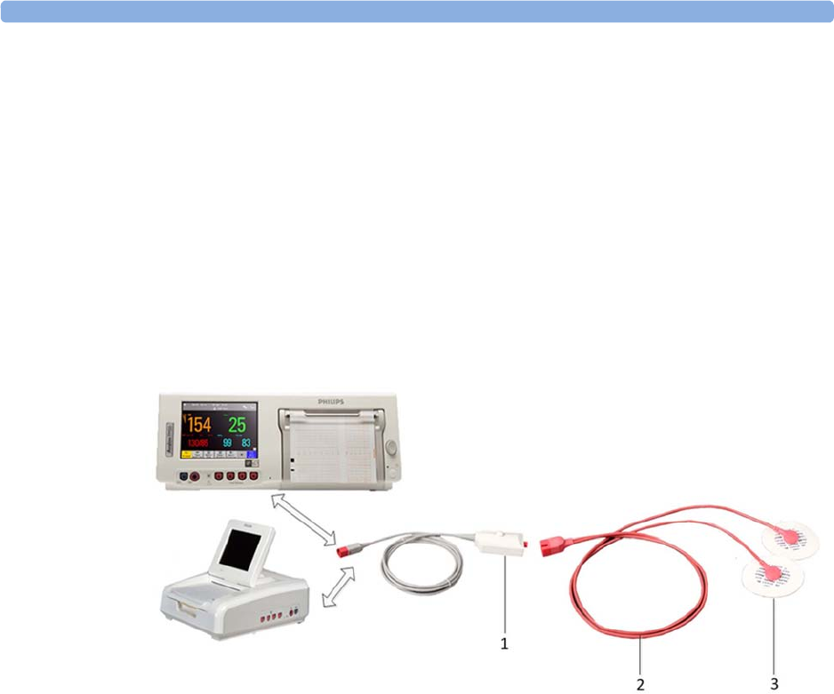
20 Monitoring Maternal Heart / Pulse Rate
222
Misidentification of Maternal HR for FHR
To reduce the possibility of mistaking the maternal HR for FHR, it is recommended that you monitor
both maternal and fetal heart rates (see “Confirm Fetal Life Before Using the Monitor” on page 10 and
“Cross-Channel Verification (CCV)” on page 159).
Maternal HR from MECG Electrodes
You can measure maternal HR using the equipment combinations shown in the following figures.
MECG with Patient Module
The figure below shows the complete connection chain from the foam electrodes applied to the
patient to the fetal monitor using the patient module.
1Patient Module (M2738A)
2MECG Adapter Cable (M1363A)
3Pre-gelled Foam Electrodes (40493A/B/C/D/E)
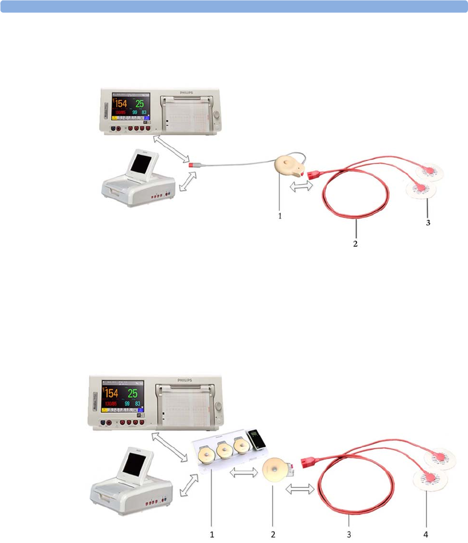
20 Monitoring Maternal Heart / Pulse Rate
223
MECG with Toco+
The figure below shows the equivalent chain using the Toco+ transducer.
1Toco+ Transducer (M2735A)
2MECG Adapter Cable (M1363A)
3Pre-gelled Foam Electrodes (40493A/B/C/D/E)
MECG with CL Toco+MP or CL ECG/IUP
The figure below shows the equivalent chain using a CL Toco+ MP transducer or a CL ECG/
IUP transducer.
1Avalon CL base station (866074)
2CL Toco+ MP (866075) or CL ECG/IUP transducer (866077)
3MECG Adapter Cable (M1363A)
4Pre-gelled Foam Electrodes (40493A/B/C/D/E)
To simultaneously measure DECG and MECG, you can use a Toco+, a CL Toco+ MP, or a
CL ECG/IUP transducer for MECG. For measuring DECG, you need a CL ECG/IUP transducer or
a patient module (see also “Monitoring FHR Using DECG” on page 199).
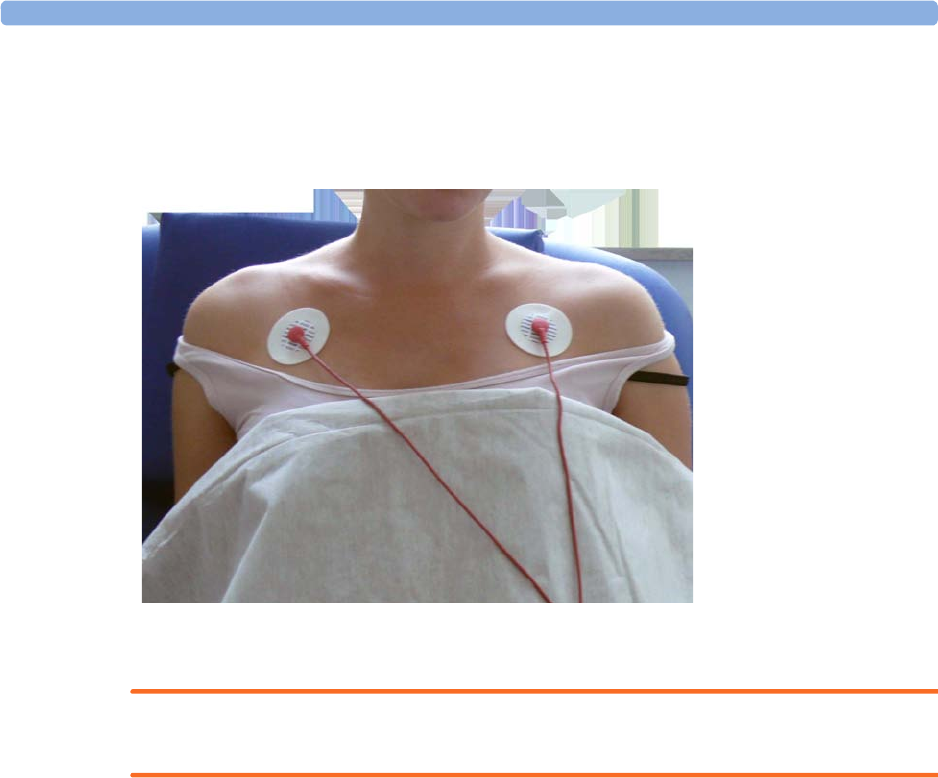
20 Monitoring Maternal Heart / Pulse Rate
224
Applying Electrodes
To derive the maternal HR (when you do not want to view the MECG waveform), you can place the
electrodes just below the outer end of the clavicle near each shoulder.
Making Connections
WARNING
Follow the instructions supplied with each of the monitoring accessories you are using.
Prepare for monitoring maternal HR using the list below. The standard procedures in use in your
facility determine the sequence of actions.
1Depending on the equipment you are using, ensure that either the Patient Module or the Toco+
transducer is connected to the fetal monitor. If you are using cableless monitoring, use the
CL ECG/IUP or the CL Toco+ MP transducer.
2Connect a pre-gelled foam electrode to each of the two leads on the MECG adapter cable.
3Apply the foam electrodes to the patient, following the instructions supplied with the foam
electrodes.
4Depending on the equipment you are using, connect the pink connector plug on the MECG
adapter cable to the pink connector on either the Patient Module or the Toco+ transducer. If you are
using cableless monitoring, connect the MECG Adapter cable to the connectors of the CL ECG/
IUP or the CL Toco+ MP transducer.
You are now ready to monitor maternal HR.
Monitoring Maternal HR
1Switch on the recorder.
2The maternal heart rate is labeled
HR
on the screen.
1MECG Electrodes
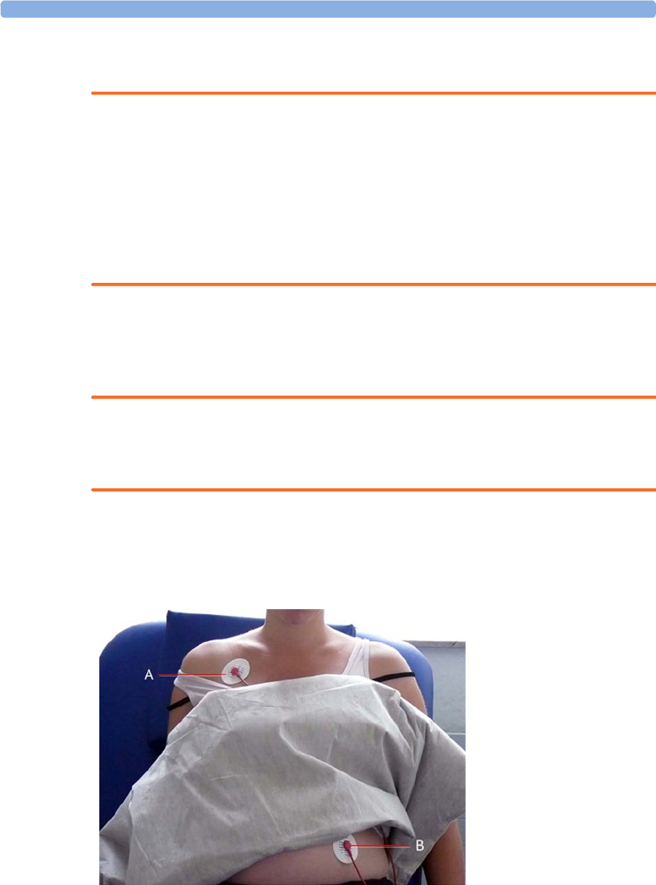
20 Monitoring Maternal Heart / Pulse Rate
225
Monitoring MECG Wave
WARNING
The fetal/maternal monitor is not a diagnostic ECG device. In particular, the display of fetal/maternal
ECG is intended only for evaluating signal quality for fetal/maternal heart rate as derived from the
ECG waveform.
When in doubt, it can be used to identify sources of compromised signal quality, such as noise or
muscle artifacts. It can subsequently be used to verify the result of measures taken to resolve them
(e.g., checking ECG cable connections or adapting the fetal
ArtifactSuppress
configuration).
The safety and effectiveness of the displayed fetal/maternal ECG waveform (i.e., P, QRS, and T
segments) for evaluation of fetal/maternal cardiac status during labor have not been evaluated.
FM30/50 When measuring MECG with the Avalon FM30 or FM50, the MECG waveform, along with the heart
rate numeric, is displayed on the screen when using a Toco+, CL Toco+ MP transducer, a patient
module, or a CL ECG/IUP transducer. If a maternal ECG wave analysis is required, use a patient
monitor.
WARNING
The fetal/maternal monitor is NOT intended for use during defibrillation, electro-surgery, or MRI.
Remove all transducers, sensors, and accessories before performing electro-surgery, defibrillation, or
MRI, otherwise harm to the patient or the user can result.
Applying Electrodes
To obtain a satisfactory maternal ECG waveform, you must use the RA to LL (lead II) position of the
standard 5-lead ECG.
1Place the RA electrode
(A) directly below the
clavicle and near the right
shoulder.
2Place the LL electrode
(B) on the left lower
abdomen.
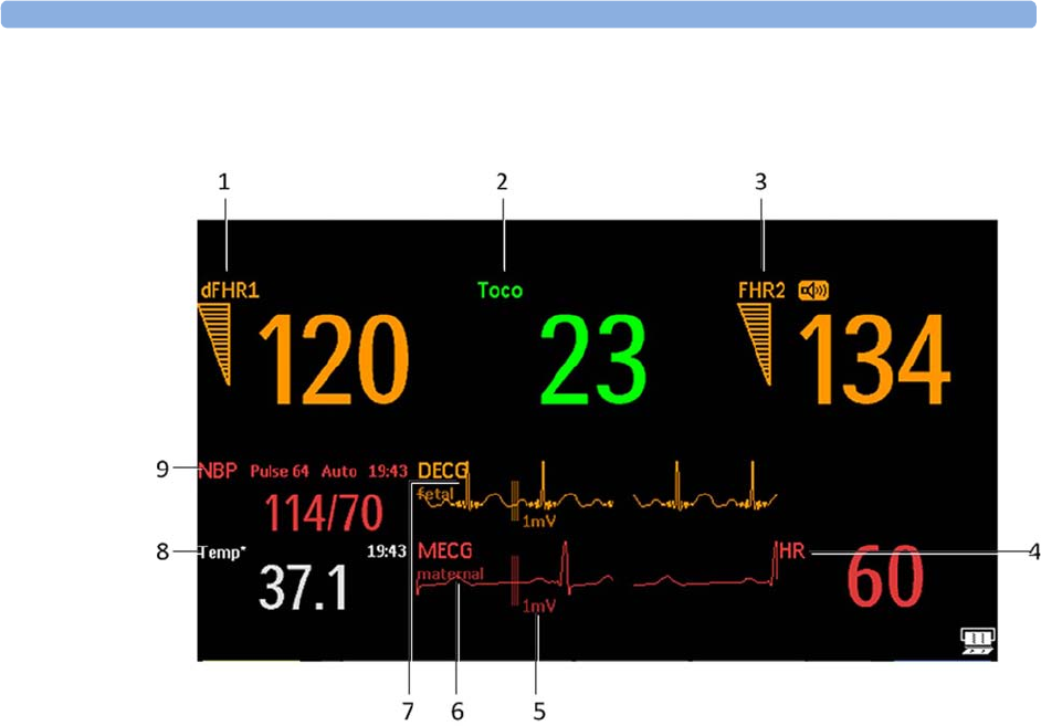
20 Monitoring Maternal Heart / Pulse Rate
226
Viewing the Waveform on the Screen
NOTE
The 1mV scale bar for the DECG and MECG wave is not displayed on the screen if you monitor
DECG or MECG with an Avalon CTS system. The Avalon CTS system does not provide a scaled
ECG.
For the FM30/50, the
MECG
wave is displayed automatically on the screen, labeled
MECG
. If
DECG
is
also being monitored (FM30/50), and the DECG Wave is configured to
On
, both waves are displayed,
with the DECG Wave above the MECG wave. The DECG Wave is labeled
DECG
.
1Measurement label dFHR1
2Measurement label Toco
3Measurement label FHR2
4Measurement label HR
51mV scale bar
6MECG wave with maternal label
7DECG wave with fetal label
8Measurement label Temp maternal temperature
9Measurement label NBP

20 Monitoring Maternal Heart / Pulse Rate
227
Troubleshooting
Printing the Waveform
You can print the MECG wave onto the trace paper. Refer to “Printing the ECG Waveform” on
page 231.
Pulse Rate from Toco MP
The maternal pulse is taken from the Toco MP or CL Toco+ MP transducer when SpO2 or MECG
measurements are not used or have signal loss. When the pulse rate is very low, or strong arrhythmia is
present, the pulse rate measured by the Toco MP or CL Toco+ MP transducer may differ from the
heart rate calculated from MECG. If the mother is moving about, or began pressing during the second
stage of labor, this can cause longer gaps in the recording of the maternal pulse signal. In this case, use
the SpO2 or MECG measurement to derive the maternal heart rate.
WARNING
• No alarm is possible when Toco MP or CL Toco+ MP transducer is the source of the pulse rate.
• No QRS tone is audible when Toco MP or CL Toco+ MP transducer is the source of the pulse
rate.
• The Toco MP or CL Toco+ MP transducer signal is significantly less reliable, if the patient is up
and moving about, or is pushing during the second stage of labor.
NOTE
In rare cases, it is possible to pick up a fetal signal source. When a Toco MP or CL Toco+ MP
transducer is connected to the monitor, but not applied to the patient, the measurement may generate
unexpected intermittent pulse readings.
Problem Possible Causes Solutions
MECG Leads Off
displayed
.
Numeric is displayed with
a -?- for 10 seconds;
INOP tone
See also “Patient Alarms
and INOPs” on page 129
One or more MECG leads is not
attached.
Make sure that all required leads are attached
If the wave is configured to be displayed on the
monitor, you can observe if the ECG signal is
clear, or if it shows interruptions and noise
Bad electrical contact Check positioning of the electrode, ensuring that
none are displaced
Check electrodes and replace if necessary
Electrodes defective
prints repeatedly
The ultrasound transducer is
measuring maternal pulse
Reposition the ultrasound transducer. See
“Recommended Actions for Coincidence
INOP” on page 164
MECG Equip Malf
displayed Equipment malfunctions See “Patient Alarms and INOPs” on page 129
MECG Unplugged
Equipment not connected

20 Monitoring Maternal Heart / Pulse Rate
228
Pulse Rate from SpO2
If you are not monitoring maternal HR via MECG electrodes, but you are monitoring SpO2, the
maternal pulse rate is derived from the SpO2 measurement. The pulse numeric is labeled
Pulse
on the
screen.
WARNING
• No QRS tone is audible when the CL SpO2 Pod is the source of the pulse rate.
Adjusting the Heart Rate / Pulse Alarm Limits
To adjust the pulse alarm limits for SpO2:
1In the
Setup SpO
menu, select
Pulse (SpO)
. This opens the
Setup Pulse (SpO)
menu.
2Ensure
Pulse (SpO)
is
On
. Select
Pulse (SpO)
to switch between
On
and
Off
.
3Set the pulse alarm limit:
– Select
High Limit
then choose the upper alarm limit for tachycardia from the pop-up list.
– Select
Low Limit
then choose the lower alarm limit for bradycardia from the pop-up list.
To adjust the pulse alarm limits for MECG:
1In the
Setup MECG
menu, select
MECG/Pulse Alarms
. This opens the
Setup Pulse
(MECG)
menu.
2Ensure
Pulse
MECG
is
On
. Select
Pulse
MECG
to switch between
On
and
Off
.
3Set the pulse alarm limit.
– Select
High Limit
then choose the upper alarm limit for tachycardia from the pop-up list.
– Select
Low Limit
then choose the lower alarm limit for bradycardia from the pop-up list.
Average Pulse Rate from Noninvasive Blood
Pressure
WARNING
No alarm is possible when noninvasive blood pressure is the source of the pulse rate.
When you are measuring noninvasive blood pressure, the monitor can also calculate the average pulse
rate. This occurs in either manual or automatic mode, when neither MECG, SpO2 nor pulse from
Toco MP or CL Toco+ MP transducer are measured. The value is displayed on the screen, and printed
on the trace. It is not the actual pulse value, but an average pulse rate, taken during the most recent
noninvasive blood pressure measurement. The value is updated after each successive measurement. If
you need a continuous measurement, you should monitor using MECG, SpO2, or pulse from
Toco MP or CL Toco+ MP transducer.

20 Monitoring Maternal Heart / Pulse Rate
229
Testing MECG Mode
See the monitor's Service Guide.

20 Monitoring Maternal Heart / Pulse Rate
230

21
231
21Printing the ECG Waveform
FM30/50 You can print the ECG wave onto the trace paper. If you are monitoring both DECG and MECG,
both waves will be printed. The start of the wave recording is annotated above the wave with
MECG
for
Maternal ECG, with
DECG
for Direct fetal ECG, and with
25 mm/sec
below the wave. When only
MECG and/or DECG are measured without any real-time recording, the
25 mm/sec
recorder speed is
printed in the trace header.
WARNING
1The fetal/maternal monitor is not a diagnostic ECG device. In particular, the display of fetal/
maternal ECG is intended only for evaluating signal quality for fetal/maternal heart rate as derived
from the ECG waveform.
When in doubt, it can be used to identify sources of compromised signal quality, such as noise or
muscle artifacts. It can subsequently be used to verify the result of measures taken to resolve them
(e.g., checking ECG cable connections or adapting the fetal
ArtifactSuppress
configuration).
The safety and effectiveness of the displayed fetal/maternal ECG waveform (i.e., P, QRS, and T
segments) for evaluation of fetal/maternal cardiac status during labor have not been evaluated.
The ECG waveform is printed along the bottom of the heart rate grid, and the three different
possibilities look like this:
DECG waveform on its own
1
DECG
2Recorder speed
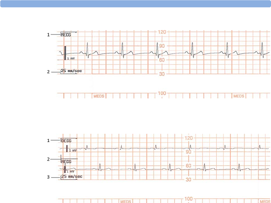
21 Printing the ECG Waveform
232
MECG waveform on its own
1
MECG
2Recorder speed
DECG and MECG waveforms
1
DECG
2
MECG
3Recorder speed
When the recorder is on, there are two choices for printing the ECG wave:
•
Separate
: This recording mode gives you a six-second ECG strip on the fetal trace paper in fast
printout mode. The real-time fetal trace recording is temporarily interrupted while the ECG strip
prints. A new MECG header is printed to mark where the MECG wave starts, and a new trace
header and FHR header mark when the fetal trace resumes.
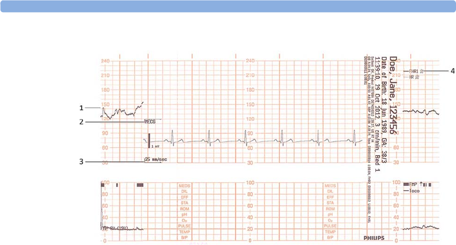
21 Printing the ECG Waveform
233
The following trace shows the MECG waveform:
1FHR1 trace interrupted
2
MECG
header
3Recorder speed
4FHR1 trace resume
•
Overlap
: This recording mode gives you a delayed six-second snapshot of the maternal and/or
direct fetal ECG for documentation on the fetal strip, but without interrupting the fetal trace. It
takes 5 minutes to print this six-second snapshot at a recorder speed of 3 cm/min. It is
documented as if it was recorded at 25 mm/s.
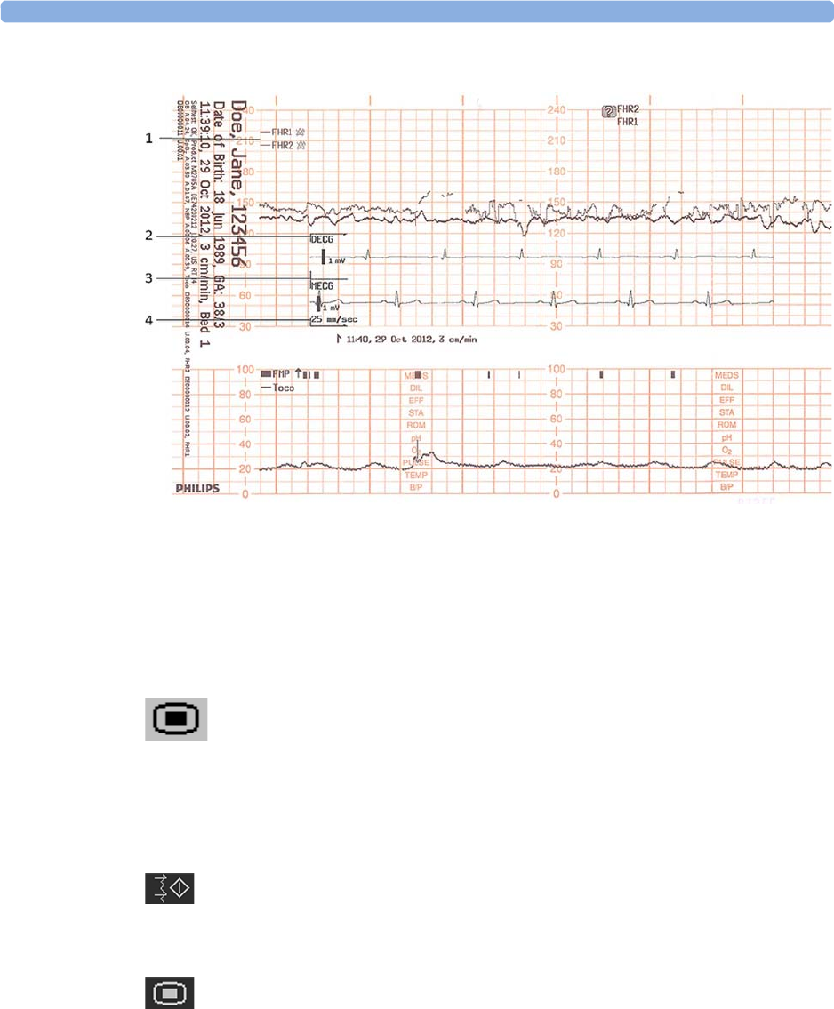
21 Printing the ECG Waveform
234
The following trace shows both the DECG and MECG waveforms:
1FHR1 and FHR2
2
DECG
header
3
MECG
header
4Recorder speed
To make your choice:
1Enter the
Main Setup
menu.
2Select
Fetal Recorder
to enter the
Fetal Recorder
menu.
3Select
ECG Wave
to switch between
Separate
and
Overlap
.
To print the ECG wave(s):
1Select the
Record ECG Wave
SmartKey (configurable) and the recording trace is started.
Or
1Enter the
Main Setup
menu by selecting the SmartKey.
2Select
Fetal Recorder
to enter the
Fetal Recorder
menu.
3Select
Record ECG Wave
and the recording trace is started.
Or
1Select the
ECG Wave
.
2Select
Record ECG Wave
in the ECG wave menu and the recording trace is started.

22
235
22Monitoring Noninvasive Blood
Pressure
The noninvasive blood pressure measurement (NBP) is intended for use with maternal patients.
This monitor uses the oscillometric method for measuring NBP.
A physician must determine the clinical significance of the NBP information.
Introducing the Oscillometric Noninvasive Blood
Pressure Measurement
Oscillometric devices measure the amplitude of pressure changes in the occluding cuff as the cuff
deflates from above systolic pressure. The amplitude suddenly increases as the pulse breaks through
the occlusion in the artery. As the cuff pressure decreases further, the pulsations increase in amplitude,
reach a maximum (which approximates to the mean pressure), and then diminish.
Studies show that, especially in critical cases (arrhythmia, vasoconstriction, hypertension, shock),
oscillometric devices are more accurate and consistent than devices using other noninvasive measuring
techniques.
WARNING
Intravenous infusion: Do not use the NBP cuff on a limb with an intravenous infusion or arterial
catheter in place. This could cause tissue damage around the catheter when the infusion is slowed or
blocked during cuff inflation.
Skin Damage: Do not measure NBP in cases of sickle-cell disease or any condition where skin
damage has occurred or is expected.
Existing Wounds: Do not apply the cuff over a wound as this can cause further injury.
Mastectomy: Avoid applying the cuff on the side of the mastectomy, as the pressure increases the risk
of lymphedema. For patients with a bilateral mastectomy, use clinical judgement to decide whether the
the benefit of the measurement outweighs the risk.

22 Monitoring Noninvasive Blood Pressure
236
Unattended Measurement: Use clinical judgement to decide whether to perform frequent
unattended blood pressure measurements. Too frequent measurements can cause blood flow
interference potentially resulting in injury to the patient. In cases of severe blood clotting disorders
frequent measurements increase the risk of hematoma in the limb fitted with the cuff.
Temporary Loss of Function: The pressurization of the cuff can temporarily cause loss of function
of monitoring equipment used simultaneously on the same limb.
Measurement Limitations
NBP readings can be affected by the position of the subject, their physiological condition, the
measurement site, and physical exercise. Thus a physician must determine the clinical significance of
the NBP information.
The measurement may be inaccurate or impossible:
• with excessive and continuous patient movement such as during contractions
• if a regular arterial pressure pulse is hard to detect
• with cardiac arrhythmias
• with rapid blood pressure changes
• with severe shock or hypothermia that reduces blood flow to the peripheries
• with obesity, where a thick layer of fat surrounding a limb dampens the oscillations coming from
the artery
• on an edematous extremity
Measurement Methods
There are three measurement methods:
•
Manual
- measurement on demand. Results are displayed for up to one hour.
•
Auto
- continually repeated measurements (between one and 120 minute adjustable interval). You
can make a manual measurement between two measurements in Auto Mode.
•
Sequence
- up to four measurement cycles which run consecutively, with a number of
measurements and intervals between them configurable for each cycle.
Reference Method
The measurement reference method can be Auscultatory (manual cuff) or Invasive (intra-arterial). For
further information, see the Application Note supplied on the monitor documentation DVD.
To check the current setting, select
Main Setup
,
Measurements
,
NBP
, and check whether the
Reference
setting is set to
Auscultatory
or
Invasive
. This setting can be changed in Configuration Mode.

22 Monitoring Noninvasive Blood Pressure
237
Preparing to Measure Noninvasive Blood Pressure
If possible, avoid taking measurements during contractions, because the measurement may be
unreliable, and may cause additional stress for the patient.
1Connect the cuff to the air tubing.
2Plug the air tubing into the red NBP connector. Avoid compression or restriction of pressure
tubes. Air must pass unrestricted through the tubing.
WARNING
Kinked or otherwise restricted tubing can lead to a continuous cuff pressure, causing blood flow
interference, and potentially resulting in injury to the patient.
3Make sure that you are using a Philips-approved correct sized cuff, and that the bladder inside the
cover is not folded or twisted.
A wrong cuff size, and a folded or twisted bladder, can cause inaccurate measurements. The width
of the cuff should be in the range from 37% to 47% of the limb circumference. The inflatable part
of the cuff should be long enough to encircle at least 80% of the limb.
4Apply the cuff to a limb at the same level as the heart. If it is not, you must use the measurement
correction formula to correct the measurement.
The marking on the cuff must match the artery location. Do not wrap the cuff too tightly around
the limb. It may cause discoloration, and ischemia of the extremities.
WARNING
Inspect the application site regularly to ensure skin quality and inspect the extremity of the cuffed
limb for normal color, warmth, and sensitivity. If the skin quality changes, or if the extremity
circulation is being affected, move the cuff to another site, or stop the blood pressure
measurements immediately. Check more frequently when making automatic measurements.
Correcting the Measurement if Limb is not at Heart Level
To correct the measurement if the limb is not at heart level, to the displayed value:
Recommendations For Measurements Used in Diagnosis of
Hypertension
To make a measurement for use in the diagnosis of hypertension, follow the steps below:
1Ensure the patient is comfortably seated, with their legs uncrossed, feet flat on the floor, and back
and arm supported.
2Ask the patient to relax and not talk before and during the measurement.
3If possible, wait 5 minutes before making the first measurement.
Add 0.75 mmHg (0.10 kPa) for each centimeter
higher or
Deduct 0.75 mmHg (0.10 kPa) for each
centimeter lower or
Add 1.9 mmHg (0.25 kPa) for each inch higher. Deduct 1.9 mmHg (0.25 kPa) for each inch
lower.

22 Monitoring Noninvasive Blood Pressure
238
Understanding the Numerics
Depending on the numeric size, not all elements may be visible. Your monitor may be configured to
display only the systolic and diastolic values. If configured to do so, the pulse from NBP is displayed
with the NBP numeric.
Aging Numerics
The measured NBP value, together with the corresponding pulse rate, if this is switched on, are
displayed for one hour. After that the values are regarded as invalid and are no longer displayed.
During this time, measurement values may be grayed out, or disappear from the screen after a set time,
if configured to do so. This avoids older numerics being misinterpreted as current data. The time can
be set in Configuration Mode. In
Auto
Mode, the measurement values may disappear more quickly (to
be replaced by new measurement values), if the repeat time is set to less than one hour.
Alarm Sources
If you have parallel alarm sources, the sources are displayed instead of the alarm limits.
NBP Measurement Timestamp
Depending on your configuration, the time shown beside the NBP numeric can be:
– the time of the most recent NBP measurement, also known as the "timestamp", or
– the time until the next measurement in an automatic series, displayed with a graphic
representation of the remaining time, as shown here.
• The NBP timestamp will normally show the completion time of the NBP measurement.
NBP Measurement Start Time
In
Auto
or
Sequence
mode, the monitor is configured to synchronize the measurements in a
measurement series to an "easy-to-document" time. For example, if you start the first measurement at
08:23, and the
Repeat Time
is set to
10 min
, the monitor automatically performs the next measurement
at 8:30, then 8:40, and so on, unless it has been configured to
NotSynchron.
.
During Measurements
The cuff pressure is displayed instead of the units and the repeat time. An early systolic value gives you
a preliminary indication of the systolic blood pressure during measurement.
1Alarm source
2Measurement Mode
3Timestamp/Timer
4Mean pressure
5Diastolic
6Systolic
7Alarm limits

22 Monitoring Noninvasive Blood Pressure
239
Starting and Stopping Measurements
Use the setup menu or the SmartKeys to start and stop measurements.
Enabling Automatic Mode and Setting Repetition
Time
1In the
Setup NBP
menu, select
Mode
.
2Switch between
Auto
and
Manual
, if necessary, to pick the measurement method.
3If making an automatic measurement, select
Repeat Time
, or press the
Repeat Time
SmartKey and
set the time interval between two measurements.
NOTE
Be aware that a combination of a recorder speed of less than 3 cm/min and a repetition time of less
than five minutes can result in not all noninvasive blood pressure measurements being recorded on the
fetal trace. For example, if the recorder speed is set to 1 cm/min and the repetition time is set to
two minutes, due to the low speed setting, the recorder will only be able to record every other
noninvasive blood pressure measurement. This affects only the local fetal trace recording, and all
measurements are displayed as normal on the monitor's screen.
Action to be performed Setup menu SmartKeys
Start/Stop manual measurement
Start Auto series
Stop current automatic measurement
Start/Stop
Start/ Stop
Start manual measurement
Start Auto series
-
Start NBP
Stop manual measurement
Stop current automatic measurement
-
Stop NBP
Stop automatic, or manual measurement AND series
Stop All NBP
Stop All

22 Monitoring Noninvasive Blood Pressure
240
Enabling Sequence Mode and Setting Up the
Sequence
1In the
Setup NBP
menu, select
Mode
and select
Sequence
from the pop-up menu.
2Select
Setup Sequence
to open the
Setup Sequence
window.
Up to four measurement cycles can be set up which run consecutively. For each cycle, you can set
the number of measurements and the intervals between them. If you want to run fewer than four
cycles in a sequence, you can set the number of measurements for one or more cycles to
Off
.
3Select each sequence in turn, and select the number of measurements and the time interval
between the measurements.
4To have measurements continue after the sequence, set the number of measurements for your last
cycle to
Continuous
and this cycle will run indefinitely.
CAUTION
Be aware that, if none of the cycles are set to
Continuous
, NBP monitoring will end after the last
measurement of the cycle.
When the NBP measurement mode is set to
Sequence
, the repetition time for
Auto
Mode cannot be
changed.
Choosing the Alarm Source
You can monitor for alarm conditions in systolic, diastolic, and mean pressure, either singly or in
parallel. Only one alarm is given, with the priority of mean, systolic, diastolic.
If mean is not selected as alarm source (
Sys.
,
Dia.
, or
Sys & Dia
selected), but the fetal monitor can only
derive a mean value, mean alarms will nevertheless be announced using the most recent mean alarm
limits. Check that the mean alarm limits are appropriate for the patient, even when not using mean as
the alarm source. When no value can be derived, an
NBP Measure Failed
INOP is displayed.
Menu option Pressure value monitored
Sys.
systolic
Dia.
diastolic
Mean
mean
Sys & Dia
systolic and diastolic in parallel
Dia & Mean
diastolic and mean in parallel
Sys & Mean
systolic and mean in parallel
Sys&Dia&Mean
all three pressures in parallel

22 Monitoring Noninvasive Blood Pressure
241
Assisting Venous Puncture
You can use the cuff to cause subdiastolic pressure. The cuff deflates automatically after a set time if
you do not deflate it.
1In the
Setup NBP
menu, select
VeniPuncture
.
2Puncture vein and draw blood sample.
3Reselect
VeniPuncture
to deflate the cuff.
During measurement, the display shows the inflation pressure of the cuff and the remaining time in
venous puncture mode.
Calibrating NBP
NBP is not user-calibrated. NBP pressure transducers must be verified at least once every two years by
a qualified service professional, and calibrated, if necessary. See the Service Guide for details.
1Cuff pressure
2Venous puncture measurement mode
3Time left in venous puncture mode

22 Monitoring Noninvasive Blood Pressure
242
Troubleshooting
Problem Possible Causes Solutions
Cuff will not inflate Monitor is in Service or Configuration
Mode
Technical defect Call service
Cuff tubing not connected Connect cuff tubing
High or low values
measured (against clinical
expectations)
Contraction occurring Wait until contraction has finished
Patient talking before or during
measurement
Allow patient to rest quietly, then try again
after three to five minutes
Incorrect cuff size or cuff not at heart
level
Check cuff size, level, and position
Noninvasive blood pressure reference
method set incorrectly
Check the reference method configured
(auscultation or intra-arterial) and correct if
necessary in Configuration Mode
Measurement limitations have not been
taken into account
Check the list in “Measurement Limitations”
on page 236
Displays zeros for systolic
and diastolic values.
Measurement automatically
repeats
Severe vasoconstriction at cuff site Move cuff to another limb, check for shock,
or verify blood pressure using another
method
Erratic blood pressure fluctuations due
to arrhythmias or rapid-acting drugs or
contractions
Try again, if unsuccessful, verify blood
pressure using another method
Wait until contraction has finished
Excessive patient movement or
convulsions
Restrain movement or verify blood pressure
using another method
NBP Cuff Overpress
INOP is
displayed
See “Patient Alarms and INOPs” on page 129.
NBP Equip Malf
INOP is
displayed
NBP Interrupted
INOP is
displayed
NBP Measure Failed

23
243
23Monitoring SpO2
FM30/40/50 The pulse oximetry measurement (SpO2) is intended for use with maternal patients.
Philips pulse oximetry uses a motion-tolerant signal processing algorithm, based on Fourier Artifact
Suppression Technology (FAST). It provides two measurements:
• Oxygen saturation of arterial blood (SpO2) - percentage of oxygenated hemoglobin in relation to
the sum of oxyhemoglobin and deoxyhemoglobin (functional arterial oxygen saturation).
• Pulse rate - detected arterial pulsations per minute. This is derived from the SpO2 value, and is one
of four sources of the maternal heart/pulse rate used for cross-channel verification (see
“Monitoring Maternal Heart / Pulse Rate” on page 221 and “Cross-Channel Verification (CCV)”
on page 159).
Selecting an SpO2 Sensor
See “Accessories and Supplies” on page 275 for a list of sensors, and the patient population and
application sites for which they are appropriate.
Familiarize yourself with the Instructions for Use supplied with your sensor before using it.
CAUTION
Do not use OxiCliq disposable sensors in a high humidity environment, or in the presence of fluids,
which may contaminate sensor and electrical connections causing unreliable or intermittent
measurements. Do not use disposable sensors when there is a known allergic reaction to the adhesive.
Applying the Sensor
1Follow the SpO2 sensor's Instructions for Use, adhering to all warnings and cautions.
2Remove colored nail polish from the application site.
3Apply the sensor to the patient. The application site should match the sensor size so that the
sensor can neither fall off, nor apply excessive pressure.
4Check that the light emitter and the photodetector are directly opposite each other. All light from
the emitter must pass through the patient's tissue.

23 Monitoring SpO2
244
WARNING
Compatibility: Use only the accessories that are specified for use with this fetal monitor, otherwise
patient injury can result.
Proper Sensor Fit: If a sensor is too loose, it might compromise the optical alignment or fall off. If it
is too tight, for example because the application site is too large or becomes too large due to edema,
excessive pressure may be applied. This can result in venous congestion distal from the application site,
leading to interstitial edema, hypoxemia, and tissue malnutrition. Skin irritations or lacerations may
occur as a result of the sensor being attached to one location for too long. To avoid skin irritations and
lacerations, periodically inspect the sensor application site and change the application site regularly.
Venous Pulsation: Do not apply sensor too tightly as this results in venous pulsation which may
severely obstruct circulation and lead to inaccurate measurements.
Ambient Temperature: At elevated ambient temperatures, be careful with measurement sites that are
not well perfused, because this can cause severe burns after prolonged application. All listed sensors
operate without risk of exceeding 41°C on the skin if the initial skin temperature does not exceed
35°C.
Extremities to Avoid: Avoid placing the sensor on extremities with an arterial catheter, an NBP cuff,
or an intravascular venous infusion line.
Connecting SpO2 Cables
Connect the sensor cable to the color-coded socket on the monitor. If you are using a disposable
sensor, plug the sensor into the adapter cable and connect this to the monitor. Connect reusable
sensors directly to the monitor.
CAUTION
Extension cables: Do not use more than one extension cable (M1941A). Do not use an extension
cable with Philips reusable sensors or adapter cables with part numbers ending in -L (indicates "long"
cable version).
Electrical Interference: Position the sensor cable and connector away from power cables, to avoid
electrical interference.
Measuring SpO2
During measurement, ensure that the application site:
– has a pulsatile flow, ideally with a signal quality indicator of at least medium.
– has not changed in its thickness (for example, due to edema), causing an improper fit of the
sensor.

23 Monitoring SpO2
245
WARNING
• For fully conscious maternal patients, who have a normal function of perfusion and sensory
perception at the measurement site:
To ensure skin quality and correct optical alignment of the sensor, inspect the application site
when the measurement results are suspicious, or when the patient complains about pressure at
the application site, but at least every 24 hours. Correct the sensor alignment if necessary.
Move the sensor to another site, if the skin quality changes.
• For all other patients:
Inspect the application site every two to three hours to ensure skin quality and correct optical
alignment. Correct the sensor alignment if necessary. If the skin quality changes, move the
sensor to another site. Change the application site at least every four hours.
• Injected dyes such as methylene blue, or intravascular dyshemoglobins such as methemoglobin
and carboxyhemoglobin may lead to inaccurate measurements.
• Inaccurate measurements may result when the application site for the sensor is deeply pigmented
or deeply colored, for example, with nail polish, artificial nails, dye, or pigmented cream.
• Interference can be caused by:
– High levels of ambient light (including IR warmers), or strobe lights or flashing lights (such as
fire alarm lamps). (Hint: cover application site with opaque material).
– Another SpO2 sensor in close proximity (e.g. when more than one SpO2 measurement is
performed on the same patient). Always cover both sensors with opaque material to reduce
cross-interference.
– Electromagnetic interference, especially when the signal quality indicator is below medium.
– Excessive patient movement and vibration.
SpO2 Signal Quality Indicator (FAST SpO2 only)
The SpO2 numeric is displayed together with a signal quality indicator (if configured and enough space
is available) which gives an indication of the reliability of the displayed values.
The level to which the triangle is filled shows the quality of the signal; the indicator below shows a
medium signal quality. The signal quality is at a maximum when the triangle is completely filled.

23 Monitoring SpO2
246
Assessing a Suspicious SpO2 Reading
Traditionally, pulse rate from SpO2 was compared with heart rate from ECG to confirm the validity of
the SpO2 reading. With newer algorithms, such as FAST-SpO2, this is no longer a valid criteria because
the correct calculation of SpO2 is not directly linked to the correct detection of each pulse.
When the pulse rate is very low, or strong arrhythmia is present, the SpO2 pulse rate may differ from
the heart rate calculated from ECG, but this does not indicate an inaccurate SpO2 value.
WARNING
With pulse oximetry, sensor movement, ambient light (especially strobe lights, or flashing lights), or
electromagnetic interference can give unexpected intermittent readings when the sensor is not
attached. Especially bandage-type sensor designs are sensitive to minimal sensor movement that might
occur when the sensor is dangling.
Understanding SpO2 Alarms
This refers to SpO2 specific alarms. See the “Alarms” on page 117 chapter for general alarm
information. SpO2 offers high and low limit alarms, and a high priority desat alarm. You cannot set the
low alarm limit below the desat alarm limit.
CAUTION
If you measure SpO2 on a limb that has an inflated noninvasive blood pressure cuff, a non-pulsatile
SpO2 INOP can occur. If the fetal monitor is configured to suppress this alarm, there may be a delay
of up to 60 seconds in indicating a critical status, such as sudden pulse loss or hypoxia.
Alarm Delays
There is a delay between a physiological event at the measurement site and the corresponding alarm at
the monitor. This delay has two components:
• The general system delay time is the time between the occurrence of the physiological event and
when this event is represented by the displayed numerical values. This delay depends on the
algorithmic processing and the averaging time.
• The time between the displayed numerical values crossing an alarm limit and the alarm indication
on the monitor. This delay is the combination of the configured alarm delay time plus the general
system alarm signal delay time.
Adjusting the SpO2 Alarm Limits
In the
Setup SpO
menu:
•Select
High Limit
then choose the upper alarm limit.
•Select
Low Limit
then choose the lower alarm limit.

23 Monitoring SpO2
247
Adjusting the Desat Limit Alarm
The Desat alarm is a high priority (red) alarm notifying you of potentially life threatening drops in
oxygen saturation.
1In the
Setup SpO
menu, select
Desat Limit
.
2Adjust the limit.
Adjusting the Pulse Alarm Limits
See “Adjusting the Heart Rate / Pulse Alarm Limits” on page 228.
Setting Up Tone Modulation
If tone modulation is on, the QRS tone pitch lowers when the SpO2 level drops. Remember, the QRS
tone is derived from either heart rate (from MECG or the CL F&M Pod) or pulse (from built-in SpO2)
depending on which is currently displayed (see “Priority for Maternal Heart / Pulse Rate” on
page 221).
NOTE
Pulse from CL SpO2 and Toco MP does not provide a QRS tone.
Setting the QRS Volume
In the
Setup SpO
menu, select
QRS Volume
and set the appropriate QRS tone volume.

23 Monitoring SpO2
248

24
249
24Monitoring Maternal
Temperature
Measuring Tympanic Temperature
The tympanic thermometer (866149) measures the patient's temperature in the ear using infrared
technology.
The result of this measurement can be automatically adjusted to correspond to a different body
reference site. The result is displayed on the screen of the thermometer and transmitted to the
monitor.
The thermometer is used with single-use probe covers for infection control during measurement.
WARNING
Do not use in the presence of flammable anesthetics, such as a flammable anesthetic mixture with air,
oxygen, or nitrous oxide.
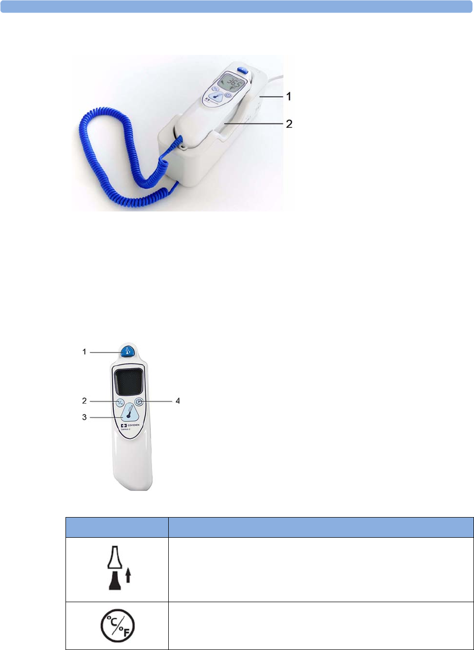
24 Monitoring Maternal Temperature
250
Place the thermometer into its base station, when it is not in use. The base station allows flexible
mounting of the thermometer at the point of care. The base station is connected to the monitor's
MIB/RS232 interface (optional) with a cable. It has storage space for up to 32 probe covers.
Thermometer Display and Controls
The tympanic thermometer has a liquid crystal display. The display shows the patient's temperature in
numerics and guides you with symbols through the measurement process.
1Base station
2Thermometer
1Eject key
2Change unit key: °Celsius/°Fahrenheit
3Start measurement key
4Pulse timer key
Functional Keys Description of Use
Press the eject key to eject the probe cover. The eject key symbol is shown
on the display when a measurement has been taken and transmitted.
Press the change unit key after a measurement to switch between °C and °F
(only affects the handheld device and not the monitor numerics).
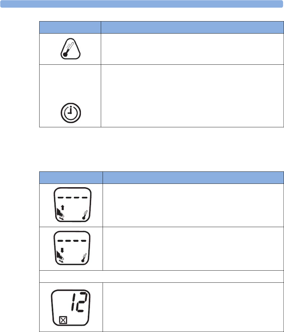
24 Monitoring Maternal Temperature
251
Status Screens
The thermometer performs an internal test at every start-up to verify that the system components are
functioning properly. It measures the ambient temperature. During start-up and measurement, the
thermometer screens communicate the current status.
Press the start measurement key when you are ready to take a patient's
temperature.
The pulse timer key can be used to time vital signs you take manually.
The pulse timer only functions after you have taken a temperature
measurement.
Press and hold the pulse timer key to enter timer mode. Press the pulse
timer key again to start the timer.
The thermometer will issue a one beep at 15 seconds, two beeps at
30 seconds, three beeps at 45 seconds, and four beeps at 60 seconds.
Functional Keys Description of Use
Images Description
Ambient temperature above specified range
Ambient temperature below specified range
System errors
System error 12 - there is a problem with the settings. Contact your
service personnel to have them check the settings and reset them, if
necessary.
If the display shows any other system error, then reset the thermometer by
picking up a probe cover. If the system error does not clear, contact your
service personnel.

24 Monitoring Maternal Temperature
252
Making a Temperature Measurement
WARNING
Inaccurate measurement results can be caused by:
• incorrect application of the thermometer
• anatomical variations in the ear
• build up of earwax in the ear
• excessive patient movement during the measurement
• absent, defective, or soiled probe covers
• probe covers other than the specified probe covers
• external environment temperature outside the range of 16ºC-33ºC (60.8ºF-91.4ºF)
1Ensure that the base station is connected with the appropriate cable to the connector on the
monitor.
2Remove the thermometer from the base station.
The thermometer is latched to the base station to avoid an accidental fall when the base station is
moved. To pick up the thermometer from the base station move it slightly up, and then lift it from
the base station to release the latch.
3Press the eject key on the thermometer to discard any probe that may have been left on the
thermometer from a previous use.
4Pick up a new probe cover from the container on the base station.
5Inspect the probe cover to make sure that it is fully seated (no space between cover and tip base)
and that there are no holes, tears, or wrinkles in the plastic film.
6Place the thermometer with the probe in the ear canal, sealing the opening with the probe tip. For
consistent results, ensure that the probe shaft is aligned with the ear canal.
7Press and release the start-up key gently.
8Wait until you hear the three beeps.
9Remove the probe from the ear.
The temperature values are displayed both on the thermometer itself, and on the connected
monitor.
10 Check that the correct temperature label for the measurement site is displayed:
iTrect
,
iToral
,
iTcore
, or
iTtymp
.
11 Press the eject key to eject the probe cover into a suitable waste receptacle.
12 Return the thermometer to the base station.
The thermometer switches to stand-by mode after 30 seconds when it is not used.
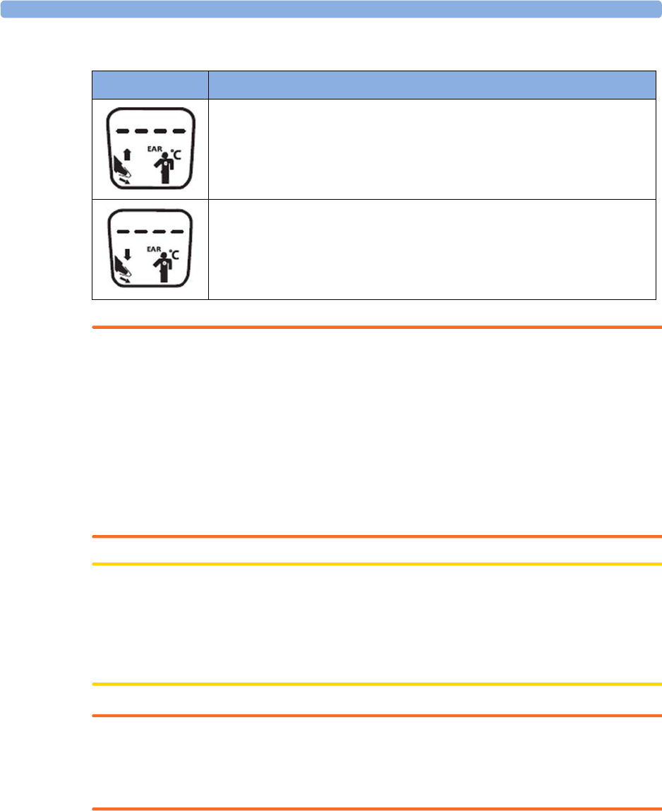
24 Monitoring Maternal Temperature
253
Possible INOPs
WARNING
• Never apply the probe to the patient when the thermometer is not connected to the base station.
• Always use a single-use probe cover to limit patient cross-contamination.
• Measurement errors or inaccurate readings may result when probe covers other than the specified
probe covers are used (see “Tympanic Temperature Accessories” on page 285).
• Insert the probe slowly and carefully to avoid damage to the ear canal and the tympanic
membrane.
• Inspect the probe cover for damage, holes, tears, or sharp edges to avoid injuring the skin.
• Always ensure that the used probe cover is removed before attaching a new probe cover.
CAUTION
• Do not immerse the probe in fluids, or drop fluids on the probe.
• Do not use a probe cover that has been dropped or is damaged.
• Do not autoclave. To prevent damage to the base station, thermometer and accessories, refer to
the cleaning procedures in the “Care and Cleaning” on page 261 chapter.
WARNING
If you have dropped the base station or thermometer, or if the unit has been stored below -25°C or
above 55°C, have service personnel test the unit for proper functions, and calibrate the unit before
further use.
The
Value Lifetime
(length of time the entered value is shown on the screen) can be configured in
Configuration Mode.
Images Description
Patient temperature above measurement range.
Patient temperature below measurement range.

24 Monitoring Maternal Temperature
254
Body Reference Sites and Monitor Labels
The tympanic thermometer measures the patient's temperature in the ear. The thermometer can be
configured to adjust the result of the measurement to correspond to a different body reference site.
The measurement label displayed on the monitor corresponds to the body reference site that is
configured. The following body reference sites are available:
The body reference site can be selected in the Biomed mode of the tympanic thermometer. Refer to
the Service Guide for more information.
The measured maternal temperature is only transmitted to a connected OB TraceVue/IntelliSpace
Perinatal system, when the tympanic thermometer is configured to the
iTtymp
body reference site, and
the
iTtymp
label is displayed on the fetal monitor screen, and printed on the trace.
Entering Temperature Manually
A temperature measurement can be entered manually.
1Press the SmartKey
Enter Temp
(configurable)
or select the SmartKey
Main Setup
, then select
Measurements
,
Enter Temp
. A numeric pad opens.
2Enter the temperature values.
3Select the
Enter
key.
Interval
Use the
Interval
setting to define the time after which a manually entered temperature value becomes
invalid (no value is then displayed).
NOTE
A manually entered temperature has to be 25ºC or higher to be transmitted to a connected obstetrical
information and surveillance system.
Body Reference Site Label on Monitor
Ear temperature (no adjustment)
iTtymp
Oral temperature
iToral
Core temperature
iTcore
Rectal temperature
iTrect

25
255
25Paper Save Mode for Maternal
Measurements
Your monitor's recorder features a Paper Save Mode, where maternal vital signs are recorded using less
paper than during a normal trace recording.
When Paper Save Mode is enabled, and if the recorder is stopped, it will start automatically to print
data from maternal measurements as they occur, and then stops again to save paper. You enable Paper
Save Mode in Configuration Mode (default is off).
• A header is printed first before the measurements are recorded. A new header is also printed when
there is a date change at midnight.
• Each NBP measurement is recorded. The time when the measurement ended is recorded.
• Each Temperature measurement is recorded. The time when the measurement ended is recorded.
• Other maternal parameters (SpO2, maternal heart rate, or Pulse) are recorded every five minutes.
The rules described in the section “Priority for Maternal Heart / Pulse Rate” on page 221 apply.
• Paper Save Mode recording stops if there are no valid maternal measurements for more than one
hour, and a message will notify you that there are no active parameters. Paper Save Mode recording
will restart automatically when another valid measurement is made.
Event Paper Save Mode
Reactivation
One of the maternal measurements (see above) is valid again. yes
The recorder is turned off and on again or a report has been recorded
(e.g. NST Report).
yes
The Paper Advance function is used. yes
The Paper Save Mode setting is set off and on again. yes
ADT information has changed (e.g. because patient information has
been completed or updated).
no
The monitor is restarted (e.g. by switching it off and on again). yes
The date has changed (e.g. at midnight). no

25 Paper Save Mode for Maternal Measurements
256

26
257
26Recovering Data
The monitor stores trace data, including annotations, for a minimum of 3.5 hours with the software
revision J.3 or higher, and for a minimum of 7 hours with the new mainboard hardware revision
A 00.18, in its internal backup memory. This allows the monitor to recover trace data that would
otherwise be lost under certain circumstances. In the event of the paper running out, this trace
recovery data can be automatically retrieved and printed, or automatically transmitted to an
OB TraceVue/IntelliSpace Perinatal system (LAN connection only), allowing continuity of data.
The fetal trace printed from the trace recovery data contains all data from the real-time trace.
Note that the data in the memory is cleared when a software upgrade is performed.
CAUTION
Only use Philips paper. Using paper other than Philips paper may result in the failure to recover traces.
Recovering Traces on Paper
The monitor is able to recover traces by printing them out at a high speed from the monitor's backup
memory. If the monitor runs out of paper, or if the paper drawer is open, the exact time when this
happens is stored in the backup memory. If the
Bridge Paperout
setting is set to
On
(default), when new
paper is loaded and the recorder is started, a trace recovery printout of the data recovered from the
backup memory is automatically printed out at high speed (up to 20 mm/s), starting from the time
noted in the backup memory. This ensures that no data is lost. A minimum of one hour of trace
recovery data is available for printing out from the backup memory. When the trace recovery printout
has finished, the recorder automatically switches back to continue recording the current trace at the
normal speed.
Note the following:
• If you press the fetal recorder
Start/ Stop
SmartKey during a trace recovery printout, the recording
stops, and the next recording following a recorder restart will be a normal, real-time trace.
After switching off the monitor, and then back on again, or following a power failure, the time of
the last
Check Paper
INOP or paper-out detection is lost, and therefore any trace recovery data in
the backup memory is no longer available to print. The next recording made following a restart of
the recorder is a normal, real-time trace.

26 Recovering Data
258
• The change back to a real-time recording from a trace recovery printout prompts the recording to
restart. A new vertical trace header annotation consisting of the time, date, and recorder speed is
printed, letting you see where the trace recovery printout ends, and where the real-time trace
continues.
• There can be a gap of up to 30 seconds between the trace recovery printout, and the beginning of
the real-time trace.
Recovering Traces on an OB TraceVue/IntelliSpace
Perinatal System
The trace recovery data stored in the monitor's backup memory can also be uploaded at high speed to
an OB TraceVue/IntelliSpace Perinatal system connected over the LAN interface (OB TraceVue
Revision E.00.00 or later, and IntelliSpace Perinatal H.0 or later).
When the OB TraceVue/IntelliSpace Perinatal system reconnects to the fetal monitor and detects that
there is trace recovery data in the monitor's backup memory that has not yet been transmitted to the
system, this data is transferred at high speed to the system. No user action is required.
The exact length of the recovered trace will vary depending on the amount of trace information, but it
will cover at least 3.5 hours of trace data with the software revision J.3 or higher, and 7 hours with
the new mainboard hardware revision A 00.18, depending on the number of active parameters.
To recover traces on an OB TraceVue/IntelliSpace Perinatal system, the following applies:
• The trace data in the monitor's internal memory must relate to a specific patient in the
OB TraceVue/IntelliSpace Perinatal system. In other words, there were no discharge events made
on the monitor that would change the patient context.
• The patient must have an open episode. No data will be uploaded if the patient is not admitted to
OB TraceVue/IntelliSpace Perinatal. For further details see the OB TraceVue/IntelliSpace
Perinatal Instructions for Use.
• Current online trace data is held back until the fast upload is complete.
Manually Recording Stored Data
If the recorder is not running, you can choose to print trace data from the monitor's memory at any
time. You can see a list of all stored traces, showing patient identification and trace period, in the
Stored Data Recording
window, from which you can choose one of the entries at a time.
CAUTION
Ensure that you admit each patient by name, including other patient identification information, and
discharge the patient when you have finished monitoring, so that you can identify which trace period
(entry in the patient list) refers to which patient.
Trace storage can be triggered by:
• Discharging a patient
• Powering on the monitor
• Entering Standby
• Entering Service Mode

26 Recovering Data
259
Traces are not available for periods the monitor was switched off, in Service Mode, in Standby, or if
the trace period was shorter than one minute.
The speed of the printout depends on the configured recorder speed and on the amount of trace data
available. The fetal trace printed from the trace data contains all data from the real-time trace, with the
exception of the maternal heart rate, the pulse numeric, and the ECG wave.
Information for scale type, trace separation, and recorder speed are not stored in the trace memory,
but is applied when the stored recording starts. While the stored recording is printing, all functions are
disabled, except that for stopping the recorder.
To start a stored data recording:
Either
1Select the
Stored Data Rec
SmartKey.
2Select
All
to print all stored trace data for the selected entry, or select one of the choices on the
other pop-up keys to print only a specified portion of the entry (for example,
Last 15 min
for the
last 15 minutes of trace data).
Or
1Enter the
Main Setup
menu using the SmartKey.
2Select
Fetal Recorder
to open the
Fetal Recorder
menu.
3Select
Stored Data Rec
to open the
Stored Data Recording
window.
4Select an entry for a patient.
5Select
All
to print all stored trace data for the selected entry, or select one of the choices on the
other pop-up keys to print only a specified portion of the entry (for example,
Last 15 min
for the
last 15 minutes of trace data).
To delete all stored trace periods:
Either
1Select the
Stored Data Rec
SmartKey.
2Select the
Erase All
key to delete all stored trace periods listed.
3Select the
Confirm
key.
Or
1Enter the
Main Setup
menu using the SmartKey.
2Select
Fetal Recorder
to open the
Fetal Recorder
menu.
3Select
Stored Data Rec
to open the
Stored Data Recording
window.
4Select the
Erase All
key to delete all stored trace periods listed.
5Select the
Confirm
key.

26 Recovering Data
260
The current patient’s entry is at the top of the list. The oldest entry at the bottom of the list has no start
time specified, as part of the data originally stored may have been over-written by the current patient’s
data.
It may be that you only see one entry (the current patient’s data) in the
Stored Data Recording
window if
that patient was monitored for a period long enough to erase any earlier entries.
If you make a stored data recording for an old entry (that is, not for the current patient), the recorder
performs a fast trace printout of the stored data, advances the paper to the next paper fold, then stops.
If you make a stored data recording for the current patient, the recorder performs a fast trace printout
of the stored data, and then reverts automatically to recording the real-time trace.

27
261
27Care and Cleaning
Use only the Philips-approved substances and methods listed in this chapter to clean or disinfect your
equipment. Warranty does not cover damage caused by using unapproved substances or methods.
Philips makes no claims regarding the efficacy of the listed chemicals, or methods as a means for
controlling infection. Consult your hospital’s Infection Control Officer or Epidemiologist. For
comprehensive details on cleaning agents and their efficacy refer to “Guideline for Disinfection and
Sterilization in Healthcare Facilities” issued by the U.S. Department of Health and Human Services,
Public Health Service, Centers for Disease Control, Atlanta, Georgia, 2008. See also any local policies
that apply within your hospital, and country.
General Points
The transducers and patient modules are sensitive instruments. Handle them with care.
Keep your monitor, transducers, patient modules, cables, and accessories free of dust and dirt. After
cleaning and disinfection, check the equipment carefully. Do not use if you see signs of deterioration
or damage. If you need to return any equipment to Philips, always decontaminate it first before
sending it back in appropriate packaging.
Observe the following general precautions:
• Always follow carefully and retain the instructions that accompany the specific cleaning and
disinfecting substances you are using.
• Always dilute cleaning agents according to the manufacturer's instructions or use lowest possible
concentration.
• Do not allow liquid to enter the case.
• Do not immerse the monitor in liquid. Protect it against water sprays or splashes.
• Do not pour liquid onto the system.
• Never use abrasive material (such as steel wool or silver polish).
• Never use bleach.

27 Care and Cleaning
262
WARNING
• Do not operate the monitor if it is wet. If you spill liquid on the monitor, contact your service
personnel or Philips service engineer.
• Do not perform underwater monitoring (for example, in a bath or shower) using wired
transducers.
• Place the monitor where there is no chance of contact with, or falling into water or other liquid.
• Do not dry equipment using heating devices such as heaters, ovens (including microwave ovens),
hair dryers, and heating lamps.
• Do not put equipment or accessories in autoclave (for sterilization).
Cleaning and Disinfecting
Clean and disinfect the Avalon FM20, FM30, FM40, and FM50 fetal monitors and the transducers
M2734A, M2734B, M2735A, M2736A, and M2738A (including ECG adapter cables) and the
Avalon CL base station and the cableless transducers after each use. Clean equipment before
disinfecting. For other accessories, see “Cleaning and Disinfecting Monitoring Accessories” on
page 263.
Clean with a lint-free cloth, moistened with warm water (40°C/104°F maximum) and soap, a diluted
non-caustic detergent, tenside, or phosphate-based cleaning agent. Do not use strong solvents such as
acetone or trichloroethylene. After cleaning, disinfect using only the approved disinfecting agents listed
(see “Recommended Disinfectants” on page 263).
CAUTION
Solutions: Do not mix disinfecting solutions (such as bleach and ammonia) as hazardous gases may
result.
Hospital policy: Disinfect the product as determined by your hospital's policy, to avoid long-term
damage to the product.
Local requirements: Observe local laws governing the use of disinfecting agents.
Touch display: To clean and disinfect the touch-enabled display, disable the touch operation by
switching off the monitor during the cleaning procedure, or by selecting and holding the
Main Screen
key until the padlock symbol appears on it, indicating that touch operation is disabled. Select and hold
again to re-enable touch operation.
WARNING
Skin contact: To reduce the risk of skin irritations, do not allow a cleaning or disinfecting agent to
leave residues on any of the equipment surfaces - wipe it off with a cloth dampened with water, after
allowing the appropriate time for the agent to work. Follow the safety instructions of the used cleaning
or disinfection agent, especially regarding skin contact.

27 Care and Cleaning
263
Take extra care when cleaning the screen of the monitor, because it is more sensitive to rough cleaning
methods than the housing. Do not permit any liquid to enter the monitor case and avoid pouring it on
the monitor while cleaning. Do not allow water or cleaning solution to enter the measurement
connectors. Wipe around and not over connector sockets, or those of the Toco+, CL Toco+ MP
transducer, ECG and IUP Patient Modules, CL ECG/IUP transducer and adapter cables.
Wash soiled reusable belts with soap and water. Water temperature must not exceed 60°C/140°F.
Recommended Disinfectants
We recommend that you use one of the following disinfectants:
Cleaning and Disinfecting Monitoring Accessories
To clean, disinfect and sterilize reusable transducers, sensors, cables, leads, and so forth, refer to the
instructions delivered with the accessory.
Do not allow a cleaning or disinfecting agent to leave residues on any of the equipment surfaces. Wipe
residues off, after allowing the appropriate time to for the agent to work, with a cloth.
Product Name Product Type Ingredients
Isopropanol liquid Isopropanol 80%
Bacillol® AF liquid, spray 100 g concentrate contains:
Propan-1-ol 45.0 g
Propan-2-ol 25.0 g
Ethanol 4.7 g
Bacillol®25 liquid Ethanol 100 mg/g
Propan-2-ol (= 2-Propanol) 90 mg/g
Propan-1-ol (= 1-Propanol) 60 mg/g
Meliseptol® spray 50% 1-Propanol
Accel TB RTU liquid 0.5% accelerated hydrogen peroxide
Oxivir® Tb Cleaner Disinfectant spray 0.5% accelerated hydrogen peroxide
Oxivir® Tb Wipes wipes 0.5% accelerated hydrogen peroxide
Carpe DiemTM/MC Tb
Ready-to-Use General Virucide,
Bactericide, Tuberculocide,
Fungicide, Sanitizer
spray 0.5% accelerated hydrogen peroxide
Carpe DiemTM/MC Tb Wipes wipes 0.5% accelerated hydrogen peroxide
Super Sani-Cloth
Germicidal Disposable Wipes
wipes Isopropanol 55%
quaternary ammonium chlorides 0.5%
SANI-CLOTH® PLUS
Germicidal Disposable Wipes
wipes Isopropanol 15%
quaternary ammonium chlorides 0.25%
SANI-CLOTH® HB Germicidal
Germicidal Disposable Wipes
wipes Isopropanol < 0.15%
quaternary ammonium chlorides 0.14%

27 Care and Cleaning
264
Cleaning and Disinfecting the Tympanic
Temperature Accessories
Probe and Thermometer Body
1Wipe the thermometer body clean with a damp cloth. The water temperature should not exceed
55°C (130°F). Do not soak, rinse, or submerge the thermometer under water.
You may add a mild detergent to the water.
2Clean the probe tip with a lint free swab. If the probe tip is soiled, clean it with a dampened swab.
3After you have removed all foreign matter, clean the thermometer lens at the end of the probe tip
with a lint free swab or lens wipe. The thermometer lens must be free from fingerprints and/or
smudges for proper operation.
4Thoroughly dry all surfaces before using the equipment.
CAUTION
Do not use cleaners and disinfectants such as Spray-Nine™, Phisohex™, Hibiclens™, or
Vesta-Syde™ as they may result in damage to the thermometer case.
Occasional use of a 10:1 water and hypochlorite mixture or a damp isopropyl alcohol wipe or Cidex™
or ManuKlenz™ or VIROX™ or CaviWipes™ cleansing agents is acceptable, however, prolonged or
repeated use of these chemicals may result in damage to the thermometer case and display area.
Use of a cloth or sponge is recommended for cleaning. Never use an abrasive pad or an abrasive
cleaner on the thermometer.
The thermometer is non-sterile. Do not use ethylene oxide gas, heat, autoclave, or any other harsh
method to sterilize this thermometer.
Cleaning and Disinfecting CL Transducers and CL
Pods
To clean, disinfect and sterilize reusable CL transducers and CL Pods refer to the instructions
delivered with the accessory.
Do not allow a cleaning or disinfecting agent to leave residues on any of the equipment surfaces. Wipe
residues off, after allowing the appropriate time to for the agent to work, with a cloth damp with water.
NOTE
Pay especially close attention to cleaning and wiping down the gold connection contacts.

27 Care and Cleaning
265
Sterilizing
Sterilization is not allowed for this monitor, related products, accessories, or supplies unless otherwise
indicated in the Instructions for Use that accompany the accessories and supplies.
WARNING
Do not put device and accessories in autoclave (for sterilization).

27 Care and Cleaning
266

28
267
28Maintenance
WARNING
Schedule: Failure on the part of the responsible individual hospital or institution employing the use of
this equipment to implement a satisfactory maintenance schedule may cause undue equipment failure
and possible health hazards.
In case of problems: If you discover a problem with any of the equipment, contact your service
personnel, Philips, or your authorized supplier.
Electric shock hazard: Do not open the monitor housing. Refer all servicing to qualified service
personnel.
Inspecting the Equipment and Accessories
You should perform a visual inspection before each use, and in accordance with your hospital's
policy. With the monitor switched off:
1Examine unit exteriors for cleanliness and general physical condition. Make sure that the housings
are not cracked or broken, that everything is present, that there are no spilled liquids that may have
entered the housing, and that there are no signs of abuse.
2Inspect all accessories (transducers, sensors and cables, and so forth). Do not use a damaged
accessory.
3Switch the monitor on, and make sure the display is bright enough. If the brightness is not
adequate, contact your service personnel or your supplier.
Batteries Preventive Maintenance
For the FM20/30 with a battery option, see “Using Batteries” on page 110.

28 Maintenance
268
Inspecting the Cables and Cords
1Examine all system cables, the power plug, and cord for damage. Make sure that the prongs of the
plug do not move in the casing. If damaged, replace it with an appropriate power cord.
2Inspect the cables, leads, and their strain reliefs for general condition. Make sure there are no
breaks in the insulation. Make sure that the connectors are properly engaged at each end to
prevent rotation or other strain.
3Carry out performance assurance checks as described in the monitor's Service Guide.
Maintenance Task and Test Schedule
The following tasks are for Philips-qualified service professionals. All maintenance tasks and
performance tests are documented in detail in the service documentation supplied on the monitor's
documentation DVD.
Ensure that these tasks are carried out as indicated by the monitor's maintenance schedule, or as
specified by local laws, whichever comes sooner. Contact a Philips-qualified service professional, if
your monitor needs a safety or performance test. Clean and disinfect equipment to decontaminate it
before testing or maintaining it.
Maintenance and Test Schedule Frequency
Visual Inspection Before each use.
Clean and disinfect the equipment After each use.
Safety checks according to IEC 60601-1,
and where applicable, to national
standards
At least once every two years, or as specified by local
laws.
After any repairs where the power supply has been
replaced (by an authorized service professional).
If the monitor has been dropped, it must be repaired/
checked by an authorized service agent.
Performance assurance for all
measurements
At least once every two years, or if you suspect the
measurement values are incorrect.
Noninvasive blood pressure calibration At least once every two years, or as specified by local
laws.
Tympanic Thermometer Calibration Once a year. If the unit is dropped or damaged, or if the
unit was stored at less than -25ºC or above 55ºC, check it
and calibrate it before further use.
Clean the thermal printhead At each paper pack change, or every 500 m of paper run.

28 Maintenance
269
Recorder Maintenance
Removing the Paper Guide: FM40/FM50
FM40/50 The paper guide is removable, and you can use the recorder without it. When not using the paper
guide, ALWAYS tear off the paper along the perforation to avoid possible paper misalignment (see
“Tearing Off the Paper” on page 61).
To remove the paper guide:
1Press the paper eject button to open the paper drawer.
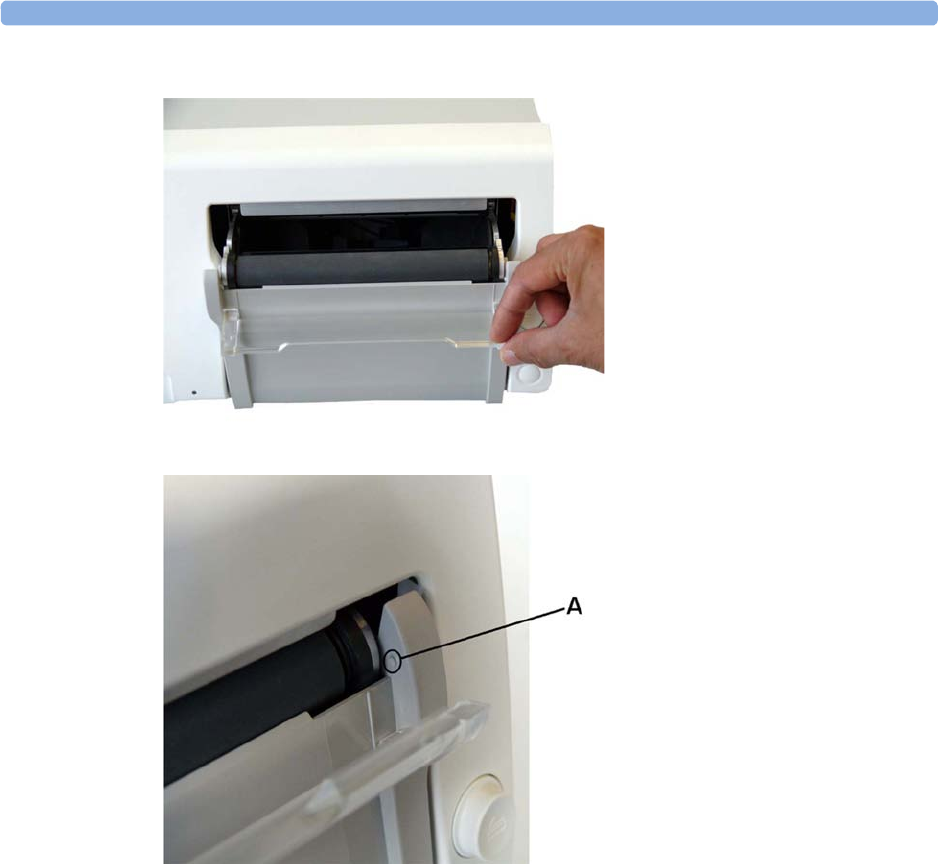
28 Maintenance
270
2Hinge the transparent paper guide forward.
3A protrusion (A) holds paper guide in closed position.
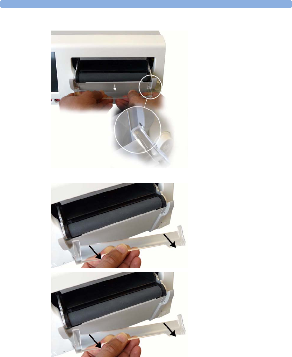
28 Maintenance
271
4Release the paper guide from one side of the holder.
5Then remove the paper guide.

28 Maintenance
272
6Refitting is a reversal of the removal procedure.
Storing Recorder Paper
Recorder paper is not intended for long-term archival storage. Another medium should be considered
if this is required.
Dyes contained in thermal papers tend to react with solvents and other chemical compounds that are
being used in adhesives. If these compounds come into contact with the thermal print, the print may
be destroyed over time. You can take the following precautionary measures to help avoid this effect:
• Store the paper in a cool, dry, and dark place.
• Do not store the paper at temperatures over 40°C (104°F).
• Do not store the paper where the relative humidity exceeds 60%.
• Avoid intensive light (UV light), as this may cause the paper to turn gray, or the thermal print to
fade.
• Avoid storing the thermal paper in combination with the following conditions:
– Papers that contain organic solvents. This includes papers with tributyl and/or dibutyl
phosphates, for example recycled paper.
– Carbon paper and carbonless copy paper.
– Products containing polyvinyl chlorides, or other vinyl chlorides for example (but not
exclusively) document holders, envelopes, letter files, divider sheets.
– Detergents and solvents, such as alcohol, ketone, ester, and others, including cleaning and
disinfecting agents.
– Products containing solvent-based adhesives such as (but not exclusively) laminating film,
transparent film, or labels sensitive to pressure.
To ensure long lasting legibility and durability of thermal printouts, store your documents separately in
an air-conditioned place and use:
• only plasticizer-free envelopes or divider sheets for protection.
• laminating films and systems with water-based adhesives.
Using such protective envelopes cannot prevent the fading effect caused by other, external agents.

28 Maintenance
273
Cleaning the Print Head
To clean the recorder's thermal print-head:
1Switch off the monitor.
2Open the paper drawer, and remove the paper if necessary, to gain access to the thermal print
head.
3Gently clean the thermal print head with a cotton swab, or soft cloth soaked in isopropyl alcohol.
NOTE
If the print head is heavily coated with dust or dirt, contact your service personnel to clean it.
Returning Equipment for Repair
Before returning equipment for repair:
• disinfect and decontaminate the equipment appropriately.
• ensure that all patient data has been removed (i.e. that no patient is admitted).
FM20/30
FM40/50

28 Maintenance
274
Disposing of the Monitor
WARNING
To avoid contaminating or infecting personnel, the environment, or other equipment, make sure that
you disinfect and decontaminate the monitor appropriately before disposing of it in accordance with
your country's laws for equipment containing electrical and electronic parts. For disposal of parts and
accessories such as thermometers, where not otherwise specified, follow local regulations regarding
disposal of hospital waste.
You can disassemble the monitor and the transducers as described in the Service Guide. You will find
detailed disposal information on the following web page:
http://www.healthcare.philips.com/main/about/Sustainability/Recycling/pm.wpd
The Recycling Passports located on the Philips web page contain information on the material content
of the equipment, including potentially dangerous materials which must be removed before recycling
(for example, batteries and parts containing mercury or magnesium).
Do not dispose of waste electrical and electronic equipment as unsorted
municipal waste. Collect it separately, so that it can be safely and properly reused,
treated, recycled, or recovered.

29
275
29Accessories and Supplies
All accessories listed for the fetal monitor may not be available in all geographies. To order parts,
accessories, and supplies, consult your local Philips representative for details. For customers in the
United States, Australia, and Great Britain you can order at www.philips.com/healthcarestore. All
accessories and supplies listed here are reusable, unless indicated otherwise.
WARNING
Reuse: Disposable accessories and supplies intended for single use, or single patient use only, are
indicated as such on their packaging. Never reuse disposable accessories and supplies, such as
transducers, sensors, electrodes, and so forth, that are intended for single use, or single patient use
only.
Approved accessories: Use only Philips-approved accessories.
Packaging: Do not use a sterilized accessory if its packaging is damaged.
Protection against electric shocks: The transducers and accessories listed in this chapter are
not defibrillator proof.
Electro-Surgery, Defibrillation and MRI: The fetal/maternal monitors are not intended for use
during defibrillation, electro-surgery, or MRI. Remove all transducers, sensors, and accessories before
performing electro-surgery, defibrillation, or MRI, otherwise harm can result.
Information on Latex
All Philips transducers and accessories are latex-free, unless indicated otherwise in the following tables.
Avalon CL Base Station
CL Base Station Part Number
Avalon CL Base Station can either be ordered with the option K30 (red connector), or
K40 (black connector), or K60 (charging station)
866074

29 Accessories and Supplies
276
Transducers
Fetal Accessories
Transducer Part Number
Avalon Toco Transducer M2734A
Avalon Toco+ Transducer for Toco, DECG, MECG, or IUP monitoring M2735A
Avalon Toco MP Transducer for Toco and Maternal Pulse M2734B
Avalon Ultrasound Transducer M2736A
Avalon Ultrasound Transducer USA M2736AA
ECG/IUP Patient Module (for DECG, MECG or IUP) M2738A
Avalon CL Toco+ MP Transducer
for use with the Avalon CL base station
866075
Avalon CL Ultrasound Transducer
for use with the Avalon CL base station
866076
Avalon CL ECG/IUP Transducer
for use with the Avalon CL base station
866077
Avalon CL Fetal & Maternal Pod
for use with the Avalon CL base station
866488
Avalon CL Wide Range Pod
for use with the Avalon CL base station
866487
CL SpO2 Pod
for use with the Avalon CL base station
865215
CL NBP Pod
for use with the Avalon CL base station
865216
Remote Event Marker 989803143411
Accessory Description Part Number
Belt (reusable, gray, water resistant) 32 mm wide, 15 m roll M4601A
60 mm wide, 5 belts M4602A
60 mm wide, 15 m roll M4603A
50 mm wide, 5 belts M1562B
Belt (disposable, yellow, water resistant) 60 mm wide, pack of 100 M2208A
Ultrasound gel 12 Bottles 40483A
5 liter refill (with dispenser) for
40483A
Shelf life: 24 months max.
40483B
Belt buttons (kit of 10) for wired transducers M273xA M1569A
Belt Clips for wired Smart Transducers (kit of 6) 989803143401

29 Accessories and Supplies
277
MECG Accessories
Avalon CL Connector Caps Connector Caps for Avalon CL
Cableless Smart Transducers (kit
of 10)
989803184841
Avalon CL Belt Clip Belt Clip for Avalon CL Cableless
Smart Transducers (kit of 10)
989803184851
Avalon CL Battery Replacement Kit 989803184861
Cable Management Kit 989803148841
Avalon CL Wide Range Battery Kit 989803196421
Kit of 20 Mobile CL Transmitter Cradles
for use with 866487 Avalon CL Wide Range Pod
989803168881
Avalon CL Fetal & Maternal Patch (case with 10 each) 989803196341
ECG Skin Preparation Paper
for use with the 989803196341 Avalon CL F&M patch
10 sheets, with 10 finger-tip sized
skin prep pieces per sheet (100
preps per bag)
M4606A
DECG Accessories: Philips DECG Solution
(NOT compatible with QwikConnect
Plus Solution accessories)
DECG reusable leg plate adapter
cable (with flushing port)
989803137651
DECG leg attachment electrode
for DECG leg plate adapter cable
989803139771
DECG fetal scalp electrode:
single spiral, worldwide
availability
989803137631
DECG fetal scalp electrode:
double spiral, Europe only. Not
for USA
989803137641
Disposable Koala IUP catheter M1333A
Reusable Koala IUP adapter cable 989803143931
Accessory Description Part Number
Accessory Part Number
MECG reusable adapter cable M1363A
Foam ECG electrodes, snap-fit, for MECG Adapter Cable (disposable) 40493D/E

29 Accessories and Supplies
278
Noninvasive Blood Pressure Accessories
The following accessories are approved for use with the fetal monitor:
Adult Multi Patient Reusable Comfort Cuffs
The tubing required for all cuffs is M1598B (1.5 m) or M1599B (3.0 m).
Adult Multi Care Reusable Cuffs
The tubing required for all cuffs is M1598B (1.5 m) or M1599B (3.0 m).
Adult EasyCare Reusable Cuffs
Maternal Patient Category Limb Circumference Part Number
Adult (Thigh) 42.0-54.0 cm M1576A
Large Adult 34.0-43.0 cm M1575A
Large Adult XL 34.0-43.0 cm M1575XL
Adult 27.0-35.0 cm M1574A
Adult XL 27.0-35.0 cm M1574XL
Small Adult 20.5-28.0 cm M1573A
Small Adult XL 20.5-28.0 cm M1573XL
Cuff kit of 4 adult sizes M1578A
Cuff kit of 4 adult XL sizes M1579XL
Maternal Patient Category Limb Circumference Part Number
Adult (Thigh) 42.0-54.0 cm 989803183371
Large Adult 34.0-43.0 cm 989803183361
Adult 27.0-35.0 cm 989803183341
Adult X-Long 27.0-35.0 cm 989803183351
Small Adult 20.5-28.0 cm 989803183331
Maternal Patient Category (color) Limb Circumference Part Number
Adult Thigh (gray) 45.0-56.5 cm M4559B
Adult Thigh (gray) pack of 5 cuffs 45.0-56.5 cm M4559B5
Large Adult X-Long (burgundy) 35.5-46.0 cm M4558B
Large Adult X-Long (burgundy) pack of 5 cuffs 35.5-46.0 cm M4558B5
Large Adult (burgundy) 35.5-46.0 cm M4557B
Large Adult (burgundy) pack of 5 cuffs 35.5-46.0 cm M4557B5
Adult X-Long (navy blue) 27.5-36.5 cm M4556B
Adult X-Long (navy blue) pack of 5 cuffs 27.5-36.5 cm M4556B5
Adult (navy blue) 27.5-36.5 cm M4555B

29 Accessories and Supplies
279
The tubing required for all cuffs is M1598B (1.5 m) or M1599B (3.0 m).
Adult Single Patient Soft Cuffs
The tubing required for all cuffs is M1598B (1.5 m) or M1599B (3.0 m).
Adult Single Care Cuffs
The tubing required for all cuffs is M1598B (1.5 m) or M1599B (3.0 m).
Adult Value Care Cuffs
The tubing required for all cuffs is M1598B (1.5 m) or M1599B (3.0 m).
Adult (navy blue) pack of 5 cuffs 27.5-36.5 cm M4555B5
Small Adult (royal blue) 20.5-28.5 cm M4554B
Small Adult (royal blue) pack of 5 cuffs 20.5-28.5 cm M4554B5
Cuff kits containing one small adult, one adult, one
large adult and one thigh cuff
864288
Cuff kits containing one small adult, one adult, one
adult X-long, one large adult, one large adult X-long
and one thigh cuff
864291
Maternal Patient Category (color) Limb Circumference Part Number
Maternal Patient Category Limb Circumference Part Number
Adult (Thigh) 45.0-56.5 cm M4579B
Large Adult X-Long 35.5-46.0 cm M4578B
Large Adult 35.5-46.0 cm M4577B
Adult X-Long 27.5-36.5 cm M4576B
Adult 27.5-36.5 cm M4575B
Small Adult 20.5-28.5 cm M4574B
Maternal Patient Category Limb Circumference Part Number
Large Adult 35.0-45.0 cm 989803182321
Adult X-Long 27.5-36.0 cm 989803182311
Adult 27.5-36.0 cm 989803182301
Small Adult 20.5-28.5 cm 989803182291
Maternal Patient Category Limb Circumference Part Number
Large Adult 34.0-43.0 cm 989803160861
Adult XL 27.0-35.0 cm 989803160851
Adult 27.0-35.0 cm 989803160841
Small Adult 20.5-28.0 cm 989803160831

29 Accessories and Supplies
280
IntelliVue CL NBP Pod Accessories
SpO2 Accessories
Some Nellcor sensors contain natural rubber latex which may cause allergic reactions. See the
Instructions for Use supplied with the sensors for more information. M1901B, M1903B, and M1904B
are not available in USA from Philips. Purchase Nellcor OxiCliq sensors and adapter cables directly
from Tyco Healthcare. Some sensors may not be available in all countries.
Do not use more than one extension cable with any sensors or adapter cables. Do not use an extension
cable with Philips reusable sensors or adapter cables with part numbers ending in -L (indicates "Long"
version).
All listed sensors operate without risk of exceeding 41°C/105.8°F on the skin if ambient temperature
is below 37°C/98.6°F.
Make sure that you use only the accessories that are specified for use with this device, otherwise patient
injury can result.
Description Limb Circumference
Range
Contents Part Number
Mobile CL Reusable Small Adult
Cuff
21-27 cm 1 cuff 989803163171
Mobile CL Reusable Adult Cuff 26.0-34.5 cm 1 cuff 989803163191
Mobile CL Reusable Large Adult
Cuff
33.5-45.0 cm 1 cuff 989803163211
Mobile CL Single-Patient Small
Adult Cuff
21-27 cm 20 cuffs 989803163181
Mobile CL Single-Patient Adult
Cuff
26.0-34.5 cm 20 cuffs 989803163201
Mobile CL Single-Patient Large
Adult Cuff
33.5-45.0 cm 20 cuffs 989803163221
Mobile CL NBP Cradle Kit - 20 cradles 989803163251
Mobile CL Extension Air Hose,
1.0 m
- 1 extension air hose 989803163131
Mobile CL NBP Battery Kit - 1 Battery
1 disassembly tool
1 front housing
989803163261
Telemetry Pouch with window - 50 pouches 989803137831
Telemetry Pouch with window - 4 boxes of 50 pouches 989803140371
White Telemetry Pouch with
Snaps
- 50 pouches 989803101971
(9300-0768-050)
White Telemetry Pouch with
Snaps
- 4 boxes of 50 pouches 989803101981
(9300-0768-200)

29 Accessories and Supplies
281
Philips Reusable Sensors
No adapter cable required.
Requires M1943A (1.0 m) or M1943AL (3.0 m) adapter cable.
No adapter cable required. SE sensors work with FM30/40/50, as well as with OxiMax-compatible
SpO2 versions of other Philips monitors.
Philips Disposable Sensors
Not available in the USA:
Requires M1943A (1.0 m) or M1943AL (3.0 m) adapter cable
Description Part Number
Adult sensor (2.0 m cable), for patients over 50 kg. Any finger, except thumb. M1191B
M1191A with longer cable (3.0 m) M1191BL
Small adult, pediatric sensor (1.5 m cable) for patients between 15 kg and 50 kg. Any
finger except thumb. Use only on adult patients with FM30/40/50.
M1192A
Ear sensor (1.5 m cable) for patients more than 40 kg. Use only on adult patients with
FM30/40/50.
M1194A
Adult clip sensor (3 m cable) for patients over 40 kg. Any finger except thumb. M1196A
Adult clip sensor (2 m cable) for patients over 40 kg. Any finger except thumb. M1196S
Description Part Number
Adult sensor (0.45 m cable), for patients over 50 kg. Any finger except thumb. M1191T
Small adult, pediatric sensor (0.45 m cable) for patients between 15 kg and 50 kg. Any
finger except thumb. Use only on adult patients with FM30/40/50.
M1192T
Adult clip sensor (0.9 m cable) for patients over 40 kg. Any finger except thumb. M1196T
Description Part Number
Special Edition (SE). Adult sensor (3 m cable), for patients over 50 kg. Any finger except
thumb.
M1191ANL
Special Edition (SE). Small adult, pediatric sensor (1.5 m cable) for patients between 15 kg
and 50 kg. Any finger except thumb. Use only on adult patients with FM30/40/50.
M1192AN
Special Edition (SE). Ear sensor (1.5 m cable) for patients more than 40 kg. M1194AN
Description Part Number
Identical to OxiMax MAX-A M1904B
Identical to OxiMax MAX-P M1903B
Identical to OxiMax MAX-N M1901B

29 Accessories and Supplies
282
Available worldwide:
Requires M1943A (1.0 m) or M1943AL (3.0 m) adapter cable
Nellcor Sensors
Nellcor sensors must be ordered from Nellcor/Covidien.
OxiMax Sensors
Require M1943A (1.0 m) or M1943AL (3.0 m) adapter cable.
Oxisensor II Sensors
Requires M1943A (1.0 m) or M1943AL (3.0 m) adapter cable.
OxiCliq Sensors
Requires M1943A (1.0 m) or M1943AL (3.0 m) adapter cable together with OC-3 adapter cable.
Description Part Number
Adult/Pediatric finger sensor (0.45 m cable). Use only on adult patients with FM30/40/
50.
M1131A
Adult/Pediatric finger sensor (0.9 m cable) for patients >40 kg. Any finger except thumb.
Use only on adult patients with FM30/40/50.
M1133A
Adult/Pediatric finger sensor (0.9 m cable) for patients >40 kg. Any finger except thumb.
Adhesive-free, use only on adult patients with FM30/40/50.
M1134A
Description Part Number
Adult finger sensor (patient size >30 kg) OxiMax MAX-A
OxiMax MAX-A with long cable OxiMax MAX-AL
Pediatric foot/hand sensor (patient size 10-50 kg). Use only on adult patients with FM30/
40/50.
OxiMax MAX-P
Adult finger or neonatal foot/hand sensor (patient size >40 kg or <3 kg). Use only on
adult patients with FM30/40/50.
OxiMax MAX-N
Description Part Number
Adult sensor (patient size >30 kg) Oxisensor II D-25
Pediatric sensor (patient size 10-50 kg). Use only on adult patients with FM30/40/50. Oxisensor II D-20
Neonatal/Adult sensor (patient size <3 kg or >40 kg). Use only on adult patients with
FM30/40/50.
Oxisensor II N-25
Description Part Number
See OxiMax MAX-A OxiCliq A
See OxiMax MAX-P. Use only on adult patients with FM30/40/50. OxiCliq P
See OxiMax MAX-N. Use only on adult patients with FM30/40/50. OxiCliq N

29 Accessories and Supplies
283
Masimo LNOP Reusable Sensors
For use with this sensor the adapter cable LNOP MP12 (M1020-61102) is needed.
Masimo LNCS Reusable Sensors
For use with this sensor the adapter cable LNC MP10 (989803148221) is needed.
Masimo LNOP Disposable Adhesive Sensors
Appropriate LNOP/LNCS adapter cable required.
Description Product Number Part Number
Adult Finger Sensor (>30 kg) LNOP DC-I 989803140321
Pediatric Finger Sensor (10-50 kg). Use only on adult
patients with FM30/40/50.
LNOP DC-IP 989803140331
Multi-Site Sensor (>1 kg). Use only on adult patients
with FM30/40/50.
LNOP YI n/a
Ear Sensor (>30 kg). Use only on adult patients with
FM30/40/50.
LNOP TC-I 989803140341
Description Product Number Part Number
Adult Finger Sensor (>30 kg) LNCS DC-I 989803148281
Pediatric Finger Sensor (10-50 kg). Use only on adult
patients with FM30/40/50.
LNCS DC-IP 989803148291
Ear Sensor (>30 kg). Use only on adult patients with
FM30/40/50.
LNCS TC-I 989803148301
Description Product Number Part Number
Adult Sensor (>30 kg) LNOP Adt 989803140231
Adult Sensor (>30 kg) LNOP Adtx n/a
Pediatric Sensor (10-50 kg). Use only on adult patients
with FM30/40/50.
LNOP Pdt 989803140261
Pediatric Sensor (10-50 kg). Use only on adult patients
with FM30/40/50.
LNOP Pdtx n/a
Neonatal (<3 kg) or Adult adhesive Sensor (>40 kg).
Use only on adult patients with FM30/40/50.
LNOP Neo-L 989803140291

29 Accessories and Supplies
284
Masimo LNCS Disposable Adhesive Sensors
Appropriate LNOP/LNCS adapter cable required.
IntelliVue CL SpO2 Pod Accessories
All listed sensors operate without risk of exceeding 41°C on the skin, if the initial skin temperature
does not exceed 35°C.
Ensure that you use only the accessories that are specified for use with this device, otherwise patient
injury can result.
1 May not be available in all geographies
Extension / Adapter Cables
Description Product Name Part Number
Adult Sensor (>30 kg) LNCS Adtx 989803148231
Pediatric Finger Sensor (10-50 kg). Use only on adult
patients with FM30/40/50.
LNCS Pdtx 989803148241
Neonatal Foot Sensor (<3 kg) or Adult Finger Sensor
(>40 kg). Use only on adult patients with FM30/40/
50.
LNCS Neo-L 989803148271
Description Contents Part Number
Mobile CL 20 single patient SpO2 Sensors
and Cradles for use on patients >10 kg
20 Single-Patient Mobile CL DSpO2-1A
Sensors
20 Single-Patient Wristbands
20 Single-Patient Cradles pre-assembled
989803165941
Mobile CL 20 single patient SpO2 Sensors
for use on patients >10 kg
20 Single-Patient Mobile CL DSpO2-1A
Sensors
989803165921
Mobile CL reusable SpO2 sensor and
Cradles for use on patients >15 kg
1 Reusable Mobile CL RSpO2-1A Sensor
20 Single-Patient Cradles with pre-attached
Wristbands
9898031659311
Mobile CL 20 SpO2 Cradles (single patient) 20 Single-Patient Cradles with pre-attached
Wristbands
989803165951
Mobile CL 50 SpO2 Wristbands (single
patient)
50 Single-Patient Wristbands 989803165961
Mobile CL SpO2 Battery Kit 1 Battery
1 disassembly tool
1 front housing
989803168861
Description Comments Part Number
Extension cable (2 m) For use with Philips reusable sensors and
adapter cables
M1941A
Adapter cable (1.1 m cable) Adapter cable for Philips/Nellcor
disposable sensors
M1943A
Adapter cable (3 m cable) M1943AL

29 Accessories and Supplies
285
Tympanic Temperature Accessories
Recorder Paper
Supplied in cases of 40 packs. Each pack has 150 numbered pages. Single use. Use the paper specified
here.
*Bradycardia and tachycardia alarm ranges are shaded.
Batteries
Adapter Cable for OxiCliq sensors Available from Nellcor OC-3
Masimo MP 12 LNOP MP Series Patient Cable (3.6 m)
Adapter Cable for Masimo LNOP sensors
M1020-61100
LNC MP10 LNCS MP Series Patient Cable (3.0 m)
Adapter Cable for Masimo LNCS sensors
989803148221
Description Comments Part Number
Description Part Number
Temperature probe 989803180831
Disposable probe cover with CE marking (22 boxes each containing 96 covers) 989803179611
Disposable probe cover (22 boxes each containing 96 covers) 989803179381
Geography FHR Scale Grid Color Scale Units Highlighted
3 cm Lines?
Part Number
USA/Canada/Asia 30-240 Red/Orange mmHg Yes M1910A
Europe 50-210 Green mmHg and kPa No M1911A
Japan 50-210 Green mmHg Yes M1913A
Japan 50-210 Green*mmHg Yes M1913J
Description Comment Part Number.
Smart Battery 10.8 V, 6000 mAh, Lithium
Ion
For Avalon FM20 or Avalon FM30 with
battery option #E25
M4605A
Avalon CL Cableless Smart transducer
Battery Replacement Kit
Consists of one Philips Lithium Ion Battery
(Part No. 453564107871), a tool to open
and close the cableless transducer for
battery replacement and two replacement
O-ring seals.
989803184861

29 Accessories and Supplies
286

30
287
30Specifications and Standards
Compliance
The monitors are intended to monitor a mother and her fetus(es), which from an electrical safety point
of view, are one person.
Environmental Specifications
The monitor may not meet the given performance specifications, if stored and used outside the
specified temperature and humidity ranges.
Avalon CL Base station 866074 with Option K30 and K40
Temperature Range Operating 0°C-45°C (32°F-113°F)
Storage/Transportation -20°C-60°C (-4°F-140°F)
Humidity Range Operating <95% relative humidity @ 45°C (113°F)
Storage/Transportation <90% relative humidity @ 60°C (140°F)
Altitude Range Operating -500-3000 m (-1640-9840 ft)
Storage/Transportation -500-13100 m (-1640-43000 ft)
Avalon CL Base station 866074 with Option K60
Temperature Range Operating 0°C-40°C (32°F-104°F)
Storage/Transportation -20°C-60°C (-4°F-140°F)
Humidity Range Operating <90% relative humidity @ 45°C (113°F)
Storage/Transportation <90% relative humidity @ 60°C (140°F)
Altitude Range Operating 0-2000 m (0-6562 ft)
Storage/Transportation -500-13100 m (-1640-43000 ft)

30 Specifications and Standards Compliance
288
NOTE
Do not locate the M2738A ECG/IUP Module directly on the patient’s skin when operated at an
environmental temperature above 37°C (98.6°F). When operated at an environmental temperature of
40°C (104°F), the transducers can reach a temperature of 41-43°C (106-110°F).
Monitor (M2702A/M2703A/M2704A/M2705A); Interface Cable for Avalon CTS (M2731-60001 and
M2732-60001)
Temperature Range Operating Without battery option: 0°C-45°C (32°F-113°F)
With battery option/charging: 0°C-35°C (32°F-95°F)
With battery option/fully charged: 0°C-40°C (32°F-
104°F)
Storage/Transportation -20°C—60°C (-4°F—140°F)
Humidity Range Operating <95% relative humidity @ 40°C (104°F)
Storage/Transportation <90% relative humidity @ 60°C (140°F)
Altitude Range Operating -500-3000 m (-1640-9840 ft)
Storage/Transportation -500-13100 m (-1640-43000 ft)
Transducers (M2734A/M2734B/M2735A/M2736A/M2738A)
Temperature Range Operating 0°C-40°C (32°F-104°F)
Storage/Transportation -20°C-60°C (-4°F-140°F)
Humidity Range Operating <95% relative humidity @ 40°C (104°F)
Storage/Transportation <90% relative humidity @ 60°C (140°F)
Altitude Range Operating -500-3000 m (-1640-9840 ft)
Storage/Transportation -500-13100 m (-1640-43000 ft)
Avalon CL Transducers (866075/866076/866077)
Temperature Range Operating 0°C-40°C (32°F-104°F)
Charging 0°C-35°C (32°F-95°F)
Storage/Transportation -20°C-60°C (-4°F-140°F)
Humidity Range Operating <95% relative humidity @ 40°C (104°F)
Storage/Transportation <90% relative humidity @ 60°C (140°F)
Altitude Range Operating -500-3000 m (-1640-9840 ft)
Storage/Transportation -500-13100 m (-1640-43000 ft)
Avalon CL Fetal and Maternal Pod (866488)
Temperature Range Operating 10°C-40°C (50°F-104°F)
Charging 10°C-35°C (50°F-95°F)
Storage/Transportation -20°C-60°C (-4°F-140°F)
Humidity Range Operating <95% relative humidity @ 40°C (104°F)
Storage/Transportation <90% relative humidity @ 60°C (140°F)

30 Specifications and Standards Compliance
289
WARNING
Explosion Hazard: Do not use in the presence of flammable anesthetics, such as a flammable
anesthetic mixture with air, oxygen, nitrous oxide, or in oxygen rich environment. Use of the devices in
such an environment may present an explosion hazard.
Physical Specifications
Fetal Monitors
Altitude Range Operating -500-3000 m (-1640-9840 ft)
Storage/Transportation -500-13100 m (-1640-43000 ft)
Avalon CL Fetal and Maternal Pod (866488)
Avalon CL Wide Range Pod (866487)
Temperature Range Operating 0°C-40°C (32°F-104°F)
Charging 0°C-35°C (32°F-95°F)
Storage/Transportation -20°C-60°C (-4°F-140°F)
Humidity Range Operating <95% relative humidity @ 40°C (104°F)
Storage/Transportation <90% relative humidity @ 60°C (140°F)
Altitude Range Operating -500-3000 m (-1640-9840 ft)
Storage/Transportation -500-4600 m (-1640-15092 ft)
SpO2 Sensors
Operating Temperature Range 0°C-37°C (32°F-98.6°F)
Tympanic Temperature
Operating Temperature Range 16ºC-33ºC (60.8ºF-91.4ºF)
Monitor Physical Specifications M2702A/M2703A M2704A/M2705A
Power Supply Voltages 100 VAC-240 VAC ±10%
Supply Frequency Range 50 Hz-60 Hz
Power Consumption
(current)
0.7-0.4 A (M2702A/M2703A)
1.3-0.7 A (M8023A#E25)
1.3-0.7 A
Dimensions and
Weight
Size (without options) mm/
(in):
width x height x depth
286 x 134 x 335 mm
(11.3 x 5.3 x 13.2 in)
425 x 174 x 365 mm
(16.6 x 6.9 x 14.4 in)
Weight <5.1 kg (11.2 lbs) <8.8 kg (19.5 lbs)
Degree of Protection Against Electrical Shock Type CF
Electrical Class Class II equipment Class I equipment

30 Specifications and Standards Compliance
290
Fetal Monitor Sounds
Avalon CL Base Station
Electrical Power Source External (AC) without battery
option #E25
Internal (Lithium Ion battery)
if with battery option #E25
External (AC)
Mode of Operation Continuous operation
Water Ingress Protection Code IP X1 (provided recorder drawer is shut)
Global Speed (DECG and MECG wave on the
screen)
6.25 mm/sec, 12.5 mm/sec, 25 mm/sec, 50 mm/sec
Startup Time Time taken from switching
on the monitor to seeing the
first parameter labels
<30 seconds
Monitor Physical Specifications M2702A/M2703A M2704A/M2705A
Source Description
Patient alarms and INOPs See the sections on “Patient Alarms and INOPs” on page 129, “Standard
Philips Alarms” on page 120, and “ISO/IEC Standard Audible Alarms” on
page 120.
Ultrasound Doppler Direct transmission of Doppler echoes to the speaker of the fetal monitor.
Pulse from SpO2, MECG, DECG QRS tone
SpO2Optional modulation of the QRS tone for changes in the SpO2 level.
NST Timer Tone for Timer expired.
Status/Prompt tone Configurable volume tone sounded when status or prompt messages are
issued by the fetal monitor.
Touch feed back tone Anytime the user touches the display a low beep is issued in response.
Avalon CL Base Station
Dimension and Weight
Size mm/(in)
W x H x D 349 x 74 x 183 mm (13.8 x 2.9 x 7.2 in)
Weight 1 kg (2.3 lbs)
Electrical Class When the base station is connected to the monitors M2702A/M2703A/M2704A/
M2705A it is a Class II equipment.
Electrical Power Source External (powered by fetal monitor)
Mode of Operation Continuous operation
Interface cable connector type Connector color Red for FM20/30 left side or FM40/50 front fetal
connector socket
Black for FM40/50 rear telemetry connector
socket
Interface cable length 1.5 m (4.11 ft)
Ingress Protection IP 31

30 Specifications and Standards Compliance
291
Wired Transducers
Avalon CL Transducers
External Power Supply (Option K60 for the Avalon CL Base Station)
Maximum Weight (with cable) 140 g (4.94 oz) (incl. cable, without country-dependent AC adapter)
Size (W x H x D) 52.0 x 39.5 x 85.0 mm (2.0 x 1.6 x 3.4 in)
Charging cable length 1.6 m (5.2 ft) (incl. power supply)
Supply Voltages 100 VAC-240 VAC
Supply Frequency Range 50 Hz/60 Hz
Power Consumption (current) 0.4-0.2A
Electrical Class Class II
Electrical Power Source AC Mains
Mode of Operation Continuous
Water Ingress Protection Code IP40
Transducers (M2734A/M2734B/M2735A/M2736A/M2738A)
Shock Resistance Withstands a 1 m drop to concrete surface with possible cosmetic
damage only
Water Ingress
Protection Code
M2734A&B/35/36A IP 68 (immersion up to 1 m water depth for 5 hours)
M2738A IP 67 (immersion up to 0.5 m water depth for 30 minutes)
Dimensions and
Weight
M2734A&B/35/36A Size (diameter) 83 mm (3.27 in)
Weight (without cable) 0.2 kg (0.5 lb)
M2738A Maximum size mm/(in):
width x height x depth
42 x 30 x 123 mm
(1.7 x 1.2 x 4.8 in)
Cable length 2.5 m
Weight 0.2 kg (0.5 lb)
Degree of Protection Against Electrical Shock Type CF
Transducer Identification Optical Signal Element (Finder LED), not M2738A
Avalon CL Transducers (866075/866076/866077)
Shock Resistance Withstands a 1.5 m drop to concrete surface with possible
cosmetic damage only.
Water Ingress Protection Code IP 68 (immersion up to 1 m water depth for 5 hours)
Dimensions
and Weight
Avalon CL Toco+ MP Transducer
866075
Size (diameter/height) 76 mm/37 mm (3 in/1.5 in)
Weight 0.2 kg (0.5 lb)
Avalon CL US Transducer 866076 Size (diameter/height) 76 mm/37 mm (3 in/1.5 in)
Weight 0.2 kg (0.5 lb)
Avalon CL ECG/IUP Transducer
866077
Size (diameter/height) 76 mm/37 mm (3 in/1.5 in)
Weight 0.2 kg (0.5 lb)

30 Specifications and Standards Compliance
292
Avalon CL Fetal & Maternal Pod
Avalon CL Wide Range Pod
Interface Cable Avalon CTS
External Power Supply Option E25
Degree of Protection Against Electrical Shock Type CF
Transducer Identification Optical Signal Element (Finder LED)
Avalon CL Transducers (866075/866076/866077)
Avalon CL Fetal & Maternal Pod (866488)
Shock Resistance Withstands a 1.5 m drop to concrete surface with possible
cosmetic damage only.
Water Ingress Protection Code IP 67 (immersion up to 1 m water depth for 30 minutes)
Dimensions and Weight W x H x D 63 x 20 x 49 mm
(2.5 x 0.8 x 1.9 in)
Weight 0.07 kg (0.15 lb)
Degree of Protection Against Electrical Shock Type CF
Pod Identification Optical Signal Element (Finder LED)
Avalon CL Wide Range Pod (866487)
Shock Resistance Withstands a 1 m drop to concrete surface with possible
cosmetic damage only.
Water Ingress Protection Code IP 32 (protection from dripping water)
Dimensions and Weight W x H x D 55 x 26.5 x 122 mm
(2.1 x 1 x 4.8 in)
Weight 0.14 kg (0.3 lb)
Interface Cable for Avalon CTS (M2731-60001 and M2732-60001)
Shock Resistance Withstands a 1 m drop to concrete surface with possible cosmetic damage only
Water Ingress Protection Code IP X1
Dimensions and Weight Maximum size mm/(in):
width x height x depth
55 x 28 x 50 mm (2.2 x 1.1 x 2.0 in)
Cable length 2.5 m
Weight 0.2 kg (0.5 lb)
M8023A (Option #E25) External Power Supply Weight and Dimensions
Maximum Weight 0.6 kg (1.4 lb)
Size (W x H x D) 208 x 105 x 89 mm (8.2 x 4.1 x 5.3 in)

30 Specifications and Standards Compliance
293
Interface Specifications
Fetal Monitors
1 The power loss indication functionality of the Nurse Call Relay board is not supported with fetal
monitors.
Interface Specifications
Network Standard 100-Base-TX (IEEE 802.3 Clause 25)
Connector RJ45 (8 pin)
Isolation Basic isolation (reference voltage: 250 V; test voltage:
1500 V)
MIB/RS232 Standard IEEE 1073-3.2-2000
Connectors RJ45 (8 pin)
Mode Software-controllable
BCC (RxD/TxD cross over) or
DCC (RxD/TxD straight through)
Power 5 V ±5%, 100 mA (max.)
Isolation Basic isolation (reference voltage: 250 V; test voltage:
1500 V)
USB Interface Standard USB 2.0 full-speed (embedded host)
Connectors USB series "Standard A" receptacle
Power Low power port 4.4V min; max. load for all ports
together 500 mA
Isolation none
RS232 (Standard) Connectors RJ45 (8 pin)
Power none
Isolation Basic isolation (reference voltage: 250 V; test voltage:
1500 V)
RS232 (Independent display
interface option)
Connectors RJ45 (8 pin)
Power none
Isolation none
Flexible Nurse Call Relay1Connectors 20 pin MDR (Mini D-Ribbon), active open and
closed contacts
Contact 100 mA, 24 V DC
Isolation Basic isolation (reference voltage: 250 V; test voltage:
1500 V)
Delay <[Configured Latency +0.5] sec

30 Specifications and Standards Compliance
294
Avalon CL Radio
*Wireless transmissions are encrypted for security.
CL Wide Range Pod Radio
Avalon CL Radio Interface Specifications
Electronic Article Surveillance (EAS) EAS tag inside the housing (58 kHz)
Short Range Radio Interface* Type Internal SRR interface
Technology IEEE 802.15.4
Frequency Band 2.4 GHz ISM (2.400-2.483 GHz)
Modulation Technique DSSS (O-QPSK)
Effective radiated power max. 0 dBm (1 mW)
Range ca. 5 m without any physical obstructions as walls
and doors
OBR (WMTS)* Frequency Band 608-614 MHz
Effective radiated power <10 mW (base station)
<1 mW (CL transducers)
Range min. 100 m/300 ft (in line of sight)
OBR (ISM)* Frequency Band 433.05-434.79 MHz
Effective radiated power <10 mW (base station)
<1 mW (CL transducers)
Range min. 100 m/300 ft (in line of sight)
OBR (T108)* Frequency Band 920.6-923.4 MHz
Effective radiated power <40 mW (base station)
<10 mW (CL transducers)
Range min. 100 m/300 ft (in line of sight)
OBR (OB Radio)
OBR (WMTS) Frequency Band 608-614 MHz
Effective radiated power <1 mW
Range 5 m/16 ft
OBR (ISM) Frequency Band 433.05-434.79 MHz
Effective radiated power <1 mW
Range 5 m/16 ft
OBR (T108) Frequency Band 920.6-923.4 MHz
Effective radiated power <5 mW
Range 5 m/16 ft
Short Range Radio Specifications
Type Built-in interface with integrated antenna
Technology IEEE 802.15.4

30 Specifications and Standards Compliance
295
Performance Specifications
Essential Performance
This section defines the essential performance for Avalon fetal monitors in combination with the
specified wired transducers and sensors, and also with the cableless measurements (Avalon CL,
Avalon CTS).
Under normal and single fault conditions either at least the performance/functionality listed in the
tables below is provided, or failure to provide this performance/functionality is readily identifiable by
the user (e.g. technical alarm, no waves and/or numeric values, complete failure of the monitor, readily
identifiable distorted signals, etc.).
Frequency Band 2.4 GHz ISM (2400-2483 GHz)
MBAN (2360-2400 GHz, for US / FCC regulated countries only)1
Modulation DSSS (O-QPSK)
Bandwidth 5 MHz
Effective Radiated Power (ERP) max. 0 dBm (1 mW)
Short Range Radio Specifications
WLAN Specifications
Type Internal wireless adapter
Technology IEEE 802.11a/b/g/n
Frequency Band USA: 2.400-2.483 GHz, 5.15-5.35 GHz, 5.725-5.825 GHz
Europe: 2.400-2.483 GHz, 5.15-5.35 GHz, 5.47-5.725 GHz
Japan: 2.400-2.483 GHz, 5.150-5.250 GHz, 5.25-5.35 GHz, 5.470-5.725 GHz
China: 2.400-2.483 GHz, 5.725-5.85 GHz
Modulation Technique 802.11b/g
DSSS (DBPSK, DQPSK, CCK)
OFDM (BPSK, QPSK, 16-QAM, 64-QAM)
802.11a
OFDM (BPSK, QPSK, 16-QAM, 64-QAM)
Effective Radiated Power (ERP) 2.400-2.483 GHz: max. 18 dBm (63 mW)
5.150-5.725 GHz: max. 19 dBm (79 mW)
5.745-5.825 GHz: max. 14 dBm (25 mW)
Measurement Essential Performance
General No interruption or cessation of current operating mode (e.g. no
reboot, display OK).
No spontaneous operation of controls (e.g. no activation of
touchscreen without user interaction).

30 Specifications and Standards Compliance
296
The table above also represents the minimum performance when operating under non-transient
electromagnetic phenomena according to IEC 60601-1-2:
• Radiated electromagnetic fields
• Conducted disturbances induced by RF fields
• Conducted disturbances induced by magnetic fields
• Voltage dips/voltage variations
The following table identifies minimum performance for transient electromagnetic phenomena
according to IEC 60601-1-2:
• Electrostatic Discharge (ESD)
• Electrical Fast Transients/Bursts
•Surges
• Voltage interruptions
ECG (Monitoring) Measurement of the fetal and maternal heart rate over the
specified measurement range and with an accuracy of ± 5 bpm.
Alarming on heart rate limit violation within specified delay time.
Maternal Pulse from Toco (MP) Measurement of the maternal pulse rate within the specified limits.
MP is susceptible to movement artifact potentially resulting in
signal loss. It is not intended for continuous maternal HR
monitoring. Limit alarms are not provided.
NBP Measurement of noninvasive systolic, diastolic, and mean blood
pressure and pulse rate within specified accuracy and error limits.
Automatic cycling
Alarming on limit violations of systolic, diastolic, and mean blood
pressure, and pulse rate.
SpO2Measurement of oxygen saturation and pulse rate within the
specified accuracy/error limits.
Alarming on oxygen saturation and pulse rate limit violation.
Temperature (tympanic) Measurement of temperature within specified accuracy/error
limits.
Alarming on temperature limit violation.
Toco extern Measurement of the external Toco ± 5 units on display and
recorder (with paper adjusted).
Toco intern (IUP) Measurement of the internal Toco within specified accuracy limits
on display and recorder (with paper adjusted).
Ultrasound Measurement of the fetal heart rate ± 5 bpm on display and
recorder (with paper adjusted).
Ultrasound energy within safe limits for continuous operation:
p_ < 1 MPa, Iob < 20 mW/cm2, Ispta < 100 mW/cm2.
Measurement Essential Performance

30 Specifications and Standards Compliance
297
Fetal Monitors
Battery Specifications
Measurement Essential Performance
All After electrostatic discharge, fast transients/bursts, surges and electro surgery
interference, the equipment will return to previous operation mode within
10 seconds (SpO2 30 seconds) without loss of any stored data.
After voltage interruptions the equipment returns to previous state without
operator intervention and loss of data.
Fetal Monitor Performance Specifications
Alarm Signal System alarm delay.
The system alarm delay is the processing
time the system needs for any alarm to be
indicated on the fetal monitor, after the
measurement has triggered the alarm.
less than 4 seconds
Pause duration 1, 2, 3 minutes or infinite, depending on the
configuration
Extended alarm pause 5 to 10 minutes
Sound pressure range min. 0 dB(A) max. 45-85 dB(A)
Review Alarms Information all alarms/INOPs, main alarms on/off, alarm
silence and time of occurrence
Capacity 300 items
Real time Clock Range from: January 1, 1997, 00:00 to:
December 31, 2080, 23:59
Accuracy better than ±1 min. per month
Hold Time infinite if powered by AC; otherwise at least
48 hours
Buffered Memory Hold Time if powered by AC infinite
without power: at least 8 hours
Contents active settings, review alarms, stored trace data
Performance Specifications
Avalon FM20/30 Battery
Option #E25
Operating Time (with new,
fully charged battery)
Basic monitoring configuration: >2 hours
(Display Brightness: 70%, Recorder: "On" at 3 cm/min,
NBP: Auto Mode at 15 min, 2 US Transducers, 1 Toco+
with MECG, 1 Patient Module with DECG)
Charge Time When monitor is off: approx. 6 hours
When monitor is in use: more than 10 hours (depending
on monitor configuration)

30 Specifications and Standards Compliance
298
Fetal / Maternal Specifications
Ultrasound
Complies with IEC 60601-2-37:2007 / EN 60601-2-37:2008
Performance Specification
Avalon CL Transducer
Battery
Operating time With a new and fully charged battery min.
10 hours
Charge time From a "low battery" indication to a "fully
charged" indication <3 hours
Charge time with Avalon FM20/30
Battery Option #E25
From a "low battery" indication to a "fully
charged" indication >6 hours.
Performance Specification
Avalon CL F&M Battery Operating time With a new and fully charged battery min.
16 hours
Charge time From a "low battery" indication to a "fully
charged" indication <3 hours
Charge time with Avalon FM20/30
Battery Option #E25
From a "low battery" indication to a "fully
charged" indication >6 hours.
Performance Specification
Avalon CL Wide Range
Pod Battery
Operating time With a new and fully charged battery min. 4 hours
Charge time From a "low battery" indication to a "fully
charged" indication <3 hours
Performance Specifications
Ultrasound
Measurement Method Ultrasound Pulse Doppler
Measurement Range US 50-240 bpm
Resolution Display 1 bpm
Printer 1/4 bpm
Jitter @ 200 bpm 3 bpm
Display Update Rate 1 per second

30 Specifications and Standards Compliance
299
Toco
US Intensity (M2736A/AA) Average output power P = (7.4 ± 0.4) mW
Peak-negative acoustic pressure p_ = (40.4 ± 4.3) kPa
Output beam intensity (Iob)
(= spatial average - temporal average
intensity)
Isata = (2.38 ± 0.59) mW/cm2
Spatial-peak temporal average intensity Ispta = (15.0 ± 3.2) mW/cm2
Effective radiating area @ -12 dB (3.11 ± 0.74) cm2
Thermal index (TI) and mechanical index (MI) are always below 1.0.
US Intensity CL (866076) Average output power P = (12.4 ± 0.4) mW
Peak-negative acoustic pressure p_ = (49.1 ± 5.2) kPa
Output beam intensity (Iob)
(= spatial average - temporal average
intensity)
Isata = (2.77 ± 0.56) mW/cm2
Spatial-peak temporal average intensity Ispta = (21.1 ± 5.1) mW/cm2
Effective radiating area @ -12 dB A-12dB = (4.47 ± 0.89) cm2
Thermal index (TI) and mechanical index (MI) are always below 1.0.
Signal Quality Indication Poor Quality empty
Acceptable Quality half-full
Good Quality full
Beat-to-Beat change (max.) for Ultrasound 28 bpm
US Frequency 1 MHz ± 100 Hz
US Signal range 3.5 μVpp-350 μVpp @ 200 Hz
US Burst Repetition Rate 3.0 kHz
Duration 100 μs
FMP Signal Range @ 33 Hz 200 μVpp-40 mVpp
Performance Specifications
Performance Specifications
Toco
Measurement Method Strain Gauge Sensor Element
Sensitivity 1 unit = 2.5 g
Resolution Display 1 unit
Printer 1/4 unit
Measurement Range 400 units
Signal Range 0-127 units
Maximum Offset Range -300 units
Baseline Setting 20 units

30 Specifications and Standards Compliance
300
IUP
ECG
Complies with IEC 60601-2-27:2011 / EN 60601-2-27:2014 except clauses listed below:
• 201.6.2, 201.8.5.5
• 201.12.1.101
• 202.6.2.101
Update Rate Display 1 per second
Printer ~4 per second
Auto Offset Correction 3 seconds after connecting the transducer, the Toco value is set
to 20 units
Auto Zero Adjust Toco value is set to zero following a negative measurement
value for 5 seconds
Performance Specifications
Performance Specifications
Maternal Pulse from Toco
Emitted Light Energy 15 mW
Wavelength Range 780-1100 nm
Range 40-240 bpm
Resolution 1 bpm
Display Update Rate 1 per second
Accuracy ± 2% or 1 bpm, whichever is greater
Update Rate every 4 seconds
Performance Specifications
IUP
Measurement Method Passive Resistive Strain Gauge Elements
Measurement Range -100-+300 mmHg
Signal Range -99-127 mmHg or (-13.2-16.9 kPa)
Resolution Display 1 mmHg
Printer 1/4 mmHg
Sensitivity 5 μV/V/mmHg
Offset Compensation +100- -200 mmHg
Accuracy (not including sensor accuracy) ±0.5% per 100 mmHg
Update Rate Display 1 per second
Printer ~4 per second
Auto Offset Correction 3 seconds after connecting the transducer, the IUP value is
set to 0 mmHg

30 Specifications and Standards Compliance
301
WARNING
The fetal/maternal monitor is not a diagnostic ECG device. In particular, the display of fetal/maternal
ECG is intended only for evaluating signal quality for fetal/maternal heart rate as derived from the
ECG waveform.
When in doubt, it can be used to identify sources of compromised signal quality, such as noise or
muscle artifacts. It can subsequently be used to verify the result of measures taken to resolve them
(e.g., checking ECG cable connections or adapting the fetal
ArtifactSuppress
configuration).
The safety and effectiveness of the displayed fetal/maternal ECG waveform (i.e., P, QRS, and T
segments) for evaluation of fetal/maternal cardiac status during labor have not been evaluated.
Performance Specifications
ECG
Performance Specifications Type DECG Single Lead ECG (derived from Fetal Scalp
Electrode)
MECG Single Lead ECG (derived from RA and LA
electrodes)
Measurement Range 30-240 bpm
Resolution Display 1 bpm (display update rate 1 per second)
Recorder 1/4 bpm
Wave Speed (Global Speed) 6.25 mm/sec, 12.5 mm/sec, 25 mm/sec, 50 mm/
sec
Accuracy ±1 bpm or 1%, whichever is greater (non-
averaging)
Beat-to-Beat change (max.) MECG: 28 bpm
DECG: 28 bpm (with Artifact Suppression On)
Differential Input Impedance >15MΩ
Electrode Offset Potential Tolerance ±400 mV
INOP Auxiliary Current (Leads Off Detection) <100 μA
Input Signal Range DECG 20 μVpp-6 mVpp
MECG 150 μVpp-6 mVpp
Dielectric Strength 1500 Vrms
Defibrillator Protection None
ESU Protection None
Paced pulse detection None

30 Specifications and Standards Compliance
302
Fetal Heart Rate (Ultrasound/DECG) Alarm Specifications
FHR Alarm Limits Range Bradycardia (low limit) 60-200 bpm adjustable in 10 bpm
steps
Default: 110 bpm
Tachycardia (high limit) 70-210 bpm adjustable in 10 bpm
steps
Default: 170 bpm
FHR Alarm Delay Range Bradycardia (low limit) Delay 10-300 seconds in steps of 10
seconds + system alarm delay
Default: 240 seconds
Tachycardia (high limit) Delay 10-300 seconds in steps of
10 seconds + system alarm delay
Default: 300 seconds
Signal Loss Delay 10-30 seconds in steps of
10 seconds + system alarm delay
MECG Alarm
Specifications
Range Adjustment Alarm Delay
MECG Alarm Limits High Range: 31-240 bpm
Default: 120 bpm
1 bpm steps (30-40 bpm)
5 bpm steps (40-240 bpm)
System alarm delay (see
“Fetal Monitors” on
page 297).
Low Range: 30-235 bpm
Default: 50 bpm
Extreme Tachycardia Difference to high limit: 0-
50 bpm
Default: 20 bpm
5 bpm steps
Clamping at: 150-240 bpm
Default: 200 bpm
5 bpm steps
Extreme Bradycardia Difference to low limit: 0-
50 bpm
Default: 20 bpm
5 bpm steps
Clamping at: 30-100 bpm
Default: 40 bpm
5 bpm steps
Maternal ECG Supplemental Information as required by IEC 60601-2-27
Heart Rate Averaging Method The maternal heart rate is computed by averaging the 12 most recent R-R
intervals. If each of three consecutive R-R intervals is greater than 1200 ms (i.e.
rate less than 50 bpm), then the four most recent R-R intervals are averaged to
compute the HR.
Display Update Rate 2 seconds
Ventricular tachycardia alarm for
waveforms B1 and B2
No heart rate is detected for waveforms B1 and B2, resulting in
*** Extreme Brady
alarm

30 Specifications and Standards Compliance
303
aFHR, aHR, aToco
Response Time of Heart Rate
Meter to Change in Heart Rate
HR change from 80-120 bpm: 10 seconds
HR change from 80-40 bpm: 14 seconds
Tall T-Wave Rejection Capability M2735A 1.2 mV T-Wave amplitude
M2738A 1.4 mV T-Wave amplitude
CL Toco+ MP,
CL ECG/IUP
1.2 mV T-Wave amplitude
Response Time of Heart Rate
meter to Change in Heart Rate
M2735A, M2738A HR change from 80-120 bpm Average: 12 seconds
HR change from 80-40 bpm Average: 15 seconds
CL Toco+ MP,
CL ECG/IUP
HR change from 80-120 bpm Average: 10 seconds
HR change from 80-40 bpm Average: 12 seconds
Heart Rate Meter Accuracy and
Response to Irregular Rhythm
M2735A, M2738A Ventricular bigeminy 40-60 bpm
Slow alternating ventricular bigeminy 45 bpm
Rapid alternating ventricular bigeminy 163 bpm
Bidirectional systoles 63-73 bpm
CL Toco+ MP,
CL ECG/IUP
Ventricular bigeminy 40-60 bpm
Slow alternating ventricular bigeminy 30 bpm
Rapid alternating ventricular bigeminy 70-163 bpm
Bidirectional systoles 63-73 bpm
Maternal ECG Supplemental Information as required by IEC 60601-2-27
aFHR
Measurement Method electrocardiography
Measurement Range 60-240 bpm
Resolution Display 1 bpm
Printer 1/4 bpm
Accuracy ±1 bpm
aHR
Measurement Method electrocardiography
Measurement Range 40-240 bpm
Resolution Display 1 bpm
Printer 1/4 bpm
Accuracy ±1 bpm
aToco
Measurement Method uterine electromyography
Measurement Range 0-500 μV

30 Specifications and Standards Compliance
304
Noninvasive Blood Pressure
Complies with IEC 80601-2-30:2009 / EN 80601-2-30:2010.
*1: Clinical investigation with the auscultatory reference method
• The 5th Korotkoff sound (K5) was used to determine the diastolic reference pressures.
• The approximation MAP = (2*DIA + SYS) / 3 was used to calculate reference MAP (mean
arterial pressure) values from the systolic and diastolic reference pressures.
Resolution 0-255 levels representing 100% of
the full scale
Accuracy ±5%
aToco
Performance Specifications
Measurement
Ranges
Systolic 30-270 mmHg (4-36 kPa)
Diastolic 10-245 mmHg (1.5-32 kPa)
Mean 20-255 mmHg (2.5-34 kPa)
Accuracy1Max. Std. Deviation: 8 mmHg (1.1 kPa)
Max. Mean Error: ±5 mmHg (±0.7 kPa)
Pulse Rate Range 40-300 bpm
Accuracy (average over
noninvasive blood
pressure measurement
cycle)
40-100 bpm: ±5 bpm
101-200 bpm: ±5% of reading
201-300 bpm: ±10% of reading
Measurement Time Typical at HR >60 bpm
Auto/manual: 30 seconds (adult)
Maximum time: 180 seconds (adult)
Cuff Inflation Time Typical for normal adult cuff: Less than 10 seconds
Initial Cuff Inflation Pressure 165 ±15 mmHg
Auto Mode Repetition Times 1, 2, 2.5, 3, 5, 10, 15, 20, 30, 45, 60, or 120 minutes
Venipuncture Mode Inflation
Inflation Pressure 20-120 mmHg (3-16 kPa)
Automatic deflation after 170 seconds
Alarm
Specifications
Range Adjustment Alarm Delay
Systolic Adult: 30-270 mmHg (4-
36 kPa)
10-30 mmHg: 2 mmHg (0.5 kPa)
>30 mmHg: 5 mmHg (1 kPa)
System alarm delay (see
“Fetal Monitors” on
page 297).
Diastolic Adult: 10-245 mmHg (1.5-
32 kPa)
Mean Adult: 20-255 mmHg (2.5-
34 kPa)

30 Specifications and Standards Compliance
305
SpO2
Complies with ISO 80601-2-61:2011 / EN 80601-2-61:2011.
Measurement Validation: The SpO2 accuracy has been validated in human studies against arterial
blood sample reference measured with a CO-oximeter. Pulse oximeter measurements are statistically
distributed, only about two-thirds of the measurements can be expected to fall within the specified
accuracy compared to CO-oximeter measurements.
Display Update Period: Typical: 2 seconds, maximum: 30 seconds. Maximum with noninvasive blood
pressure INOP suppression on: 60 seconds.
Overpressure Settings Adjustment
> 300 mmHg (40 kPa) > 2 sec not user adjustable
SpO2 Performance Specifications
SpO2
The specified accuracy is
the root-mean-square
(RMS) difference
between the measured
values and the reference
values
Range 0-100%
Accuracy Philips Reusable Sensors:
M1191A/B, M1191AL/BL, M1191ANL, M1192A, M1192AN = 2%
(70%-100%)
M1191T, M1192T, M1194A, M1194AN, M1196A, M1196T = 3%
(70%-100%)
Philips Disposable Sensors with M1943A(L):
M1131A, M1901B, M1903B, M1904B = 3% (70%-100%)
M1133A, M1134A = ±2% (70%-100%)
Nellcor® Sensors with M1943A(L):
MAX-A, MAX-AL, MAX-P, MAX-N, D-25, D-20, N-25, OxiCliq A,
P, N = 3% (70%-100%)
Masimo Reusable Sensors® with LNOP MP12 or LNC MP10:
LNOP DC-I, LNOP DC-IP, LNOP YI, LNCS DC-I, LNCS DC-IP:
2% (70%-100%)
LNOP TC-I, LNCS TC-I: 3.5% (70%-100%)
Masimo Disposable Sensors® with LNOP MP12 or LNC
MP10:
LNOP Adt, LNOP Adtx, LNOP Pdt, LNOP Pdtx, LNCS Adtx,
LNCS Pdtx: 2% (70%-100%)
LNOP Neo-L, LNCS Neo-L: 3% (70%-100%)
Resolution 1%
Pulse Range 30-300 bpm
Accuracy ±2% or 1 bpm, whichever is greater
Resolution 1 bpm

30 Specifications and Standards Compliance
306
Tympanic Temperature
Complies with:
• EN 12470-5 (Clinical thermometers - Part 5:2003: Performance of infra-red thermometers)
• ASTM E1965-98 (Infrared Thermometers for Intermittent Determination of Patient
Temperature)
with minor exceptions as noted below.
The fetal monitor additionally complies with ISO 80601-2-56:2009 / EN ISO 80601-2-56:2012.
Sensors Wavelength range 500-1000 nm.
Information about the wavelength range can be especially useful to
clinicians (for instance, when photodynamic therapy is performed).
Emitted Light
Energy
15mW
Pulse Oximeter Calibration Range 70%-100%
SpO2 Performance Specifications
SpO2 Alarm Specifications Range Adjustment Delay
SpO250-100% 1% steps (0, 1, 2, 3,... 30) +
4 seconds
Desat 50-Low alarm limit 1% steps
Pulse 30-300 bpm 1 bpm steps (30-40 bpm)
5 bpm steps (40-300 bpm)
max. 14 seconds
Tachycardia Difference to high limit 0-50 bpm 5 bpm steps max. 14 seconds
Clamping at 150-300 bpm 5 bpm steps
Bradycardia Difference to low limit 0-50 bpm 5 bpm steps max. 14 seconds
Clamping at 30-100 bpm 5 bpm steps
Performance Specifications
Temperature Resolution 0.1°C or 0.1°F
Response Time less than 2 seconds
Temperature Calibrated Accuracy Specifications (out of the Factory)
Ambient Temperature Target Temperature Accuracy
25.0°C (77.0°F) 37.7°C-38.9°C (98.4°F-102.0°F) ±0.1°C (±0.2°F)
16.0°C-33.0°C (60.8°F-91.4°F) 33.0°C-42.0°C (91.4°F-107.6°F) ±0.2°C (±0.4°F)
Temperature Calibrated Accuracy Specifications (after recalibration using Genius 2 Checker/Calibrator)
Ambient Temperature Target Temperature Accuracy
16.0°C-33.0°C (60.8°F-91.4°F) 36.0°C-39.0°C (96.8°F-102.2°F) ±0.2°C (±0.4°F)

30 Specifications and Standards Compliance
307
16.0°C-33.0°C (60.8°F-91.4°F) <36.0°C or >39.0°C
(<96.8°F or >102.2°F)
±0.3°C (±0.5°F)
ASTM laboratory requirement for IR thermometers in the display range 37.0°C-39.0°C (98.0°F-102.0°F) is ±0.2°C
(±0.4°F), whereas for mercury-in-glass and electronic thermometers, the requirement per ASTM standards E667-86
and E1112-86 is ±0.1°C (±0.2°F).
Clinical accuracy characteristics and procedures are available from Covidien llc on request. To verify the accuracy, use
a certified black body as specified in EN ISO 80601-2-56, Annex C, or use a Genius 2 Checker/Calibrator - available
from Covidien llc under part number 303097.
Clinical repeatability: meets section A.5 of EN ISO 80601-2-56(E) per Covidien llc technical report. Data is available
from Covidien llc on request.
Performance Specifications
Displayed Temperature Measurement Range
Mode Range °C Range °F
Ear 33.0-42.0°C 91.4-107.6°F
Oral (ear + 0.6°C) 33.6-42.0°C 92.5-107.6°F
Core (ear + 1.04°C) 34.0-42.0°C 93.2-107.6°F
Rectal (ear + 1.16°C) 34.2-42.0°C 93.6-107.6°F
Caution: ASTM E1965-98 specifies 34.4°C-42.2°C (94°F-108°F)
Ambient Temperature Range
Mode Range °C Range °F
Operating 10%-95% RH, non-
condensing
16.0-33.0°C 60.8-91.4°F
Storage up to 95% RH, non-
condensing
-25.0-55.0°C -13.0-131.0°F
Caution: EN ISO 80601-2-56 specifies 16.0°C-35.0°C (60.8°F-95.0°F), 10%-95% RH, non-condensing
ASTM E1965-98 specifies 16.0°C-40.0°C (60.8°F-104.0°F), up to 95% RH, non-condensing
Storing the thermometer outside the specified temperature/humidity range might adversely affect measurement
accuracy. Check the calibration after storage in uncertain conditions.
Tympanic Temperature Alarm Specifications
Range 33.0°C-42.0°C (91.0°F-108.0°F)
Adjustment 0.5°C steps (33.0°C-35.0°C)
0.1°C steps (35.0°C-42.0°C)
1.0°F steps (91.0°F-95.0°F)
0.2°F steps (95.0°F-108.0°F)
Alarm delay System alarm delay (see “Fetal Monitors” on page 297).

30 Specifications and Standards Compliance
308
Physical Specifications
Recorder Specifications
Thermometer
Dimensions 190 mm x 43 mm x 55 mm (±3 mm)
Cable length 60 ±5 cm (spiral cable relaxed)
250 ±15 cm (spiral cable extended)
Weight (including cable) 180 ±10 g
Ingress protection classification IP 21
Base Station
Dimensions 205 mm x 65 mm x 75 mm (±3 mm)
Weight (excluding cable) 400 g ±10 g
Built-in Thermal Array Fetal Trace Recorder
Mechanism Thermal Array Recorder
Paper & Printing Type Standard Z-fold paper
Standard Speeds (real-time traces) 3 cm/min, 2 cm/min, 1 cm/min
Fast Print Speed (stored traces) Max. 20 mm/s
Print speed is variable and depends on
the print load
ECG Wave Print Speed
(not real-time)
Emulated 25 mm/s
Print speed is variable and depends on
the print load
Paper Advance 20 mm/s
Sensing Optical Reflex Sensor for black page
marks
Accuracy @ 3 cm/min, 2 cm/min,
1 cm/min
±5 mm/page
Usable Print Width 128 mm
Resolution 8 dots/mm (200 dpi)
Time Delay to see trace on paper <30s @ 1 cm/min
Trace Separation Offset for FHR
(Ultrasound and DECG)
Twin Standard FHR2 +20 bpm
Classic FHR1 +20 bpm
FHR2
Triplet Standard FHR2 +20 bpm
FHR3 -20 bpm
Classic FHR1 +20 bpm
FHR3 -20 bpm
and/or FHR3
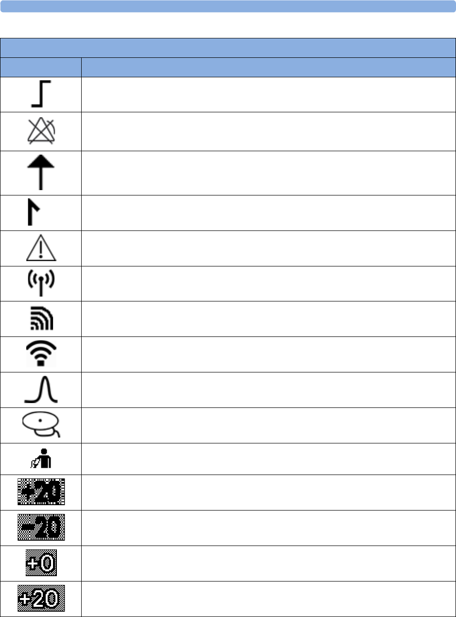
30 Specifications and Standards Compliance
309
Recorder Symbols
Symbol Description
Parameter is capable of alarming and alarms were enabled at the time of printing the annotation.
The low limit is printed before the symbol, and the high limit after it.
Parameter is capable of alarming, but alarms were disabled at the time of printing the annotation.
(Note: There is no alarm related annotation at all if a parameter does not have alarming
capability.)
FMP detection is on
Beginning of the date/time annotation
Warning (INOP)
Measurement from a cableless transducer (printed next to measurement label)
Measurement from a cableless measurement Pods
Measurement from cableless devices connected with WLAN (CL Wide Range Pod)
Pulse from SpO2
Pulse from Toco MP
Pulse from NBP
Trace separation +20 bpm (in label)
Trace separation -20 bpm (in label)
Trace separation Off (in trace)
Trace separation +20 bpm (in trace)

30 Specifications and Standards Compliance
310
External Displays: FM40/FM50 Only
External displays can be connected with a maximum cable run of 10 m. External displays must be
approved for medical use (IEC 60601-1). The video output of the Avalon FM40/FM50 has VGA
resolution.
Manufacturer's Information
You can write to Philips at this address:
Philips Medizin Systeme Boeblingen GmbH
Hewlett-Packard-Str. 2
71034 Boeblingen
Germany
Visit our website for local contact information at: www.healthcare.philips.com
© Copyright 2016. Koninklijke Philips N.V. All Rights Reserved.
Trademark Acknowledgment
OxisensorTM II, Oxi-CliqTM, and OxiMaxTM are trademarks of Tyco Healthcare Group LP, Nellcor
Puritan Bennett Division.
Trace separation -20 bpm (in trace)
Trace separation +20 bpm and -20 bpm (in trace)
Coincidence of heart rates is detected
Marker
Special wave, with different speed and scale (for example, fast printout of MECG wave on
FM30)
Recorder Symbols
Symbol Description

30 Specifications and Standards Compliance
311
Regulatory and Standards Compliance
The fetal monitors are in conformity with the requirements of the European Medical Devices
Directive 93/42/EEC and bear the CE marking:
The fetal monitors are classified into Class IIb according to Annex IX rule 10.
The Avalon CL Transducer System is in conformity with the requirements of the European Radio
Equipment and Telecommunications Terminal Equipment Directive 99/5/EC. The Avalon CL base
station used in this system is class 1 and the Avalon CL transducers of this system are class 1 under the
scope of the R&TTE Directive.
To obtain a copy of the original Declaration of Conformity, please contact Philips at the address given
in the “Manufacturer's Information” on page 310 section of this manual.
Safety and Performance
The fetal monitors comply with the following major international safety and performance standards:
• IEC 60601-1:2005+A1:2012 / EN 60601-1:2006+AC:2013
• IEC 60601-1-6:2010 / EN 60601-1-6:2013
• IEC 60601-1-8:2006+A1:2012 / EN 60601-1-8:2007+AC:2013
• IEC 60601-2-49:2011 / EN 60601-2-49:2015
• ANSI/AAMI ES60601-1:2005+A1:2012+C1:2009+A2:2010
• CAN/CSA C22.2#60601-1-08
• JIS T 1303 2005
• AS/NZS 3200.1.0-1998
The possibility of hazards arising from hardware and software errors was minimized in compliance
with ISO 14971:2012, IEC 60601-1:2005+A1:2012 / EN 60601-1:2006+AC:2013.
Alarm sounds are compliant with Standard IEC 60601-1-8:2006+A1:2012 / EN 60601-1-
8:2007+A1:2013+AC:2014.
Compatibility
When your fetal monitor is compliant with IEC 60601-1:1988+A1:1991+A2:1995 / EN 60601-
1:1990+A1:1993+A2:1995 (Edition 2) and related standards, it can still be used with the Avalon
CL Transducer System and the software upgrade J.3 or higher, and all measurement accessories that
are compliant with IEC 60601-1:2005+A1:2012 / EN 60601-1:2006+AC:2013 (Edition 3) and related
standards.
When your fetal monitor is compliant with IEC 60601-1:2005+A1:2012 / EN 60601-
1:2006+AC:2013 (Edition 3) and related standards, it can still be used with the Avalon CTS
Transducer System, and all measurement accessories that are compliant with
IEC 60601-1:1988+A1:1991+A2:1995 / EN 60601-1:1990+A1:1993+A2:1995 (Edition 2) and
related standards.

30 Specifications and Standards Compliance
312
Radio
The Avalon CL Transducer System complies with the following major international radio standards:
• ETSI EN 300 220-1:2012
• ETSI EN 300 220-2:2012
• ETSI EN 301 489-1:2011
• ETSI EN 301 489-3:2013
• FCC 47 CFR Part 95
• IC RSS-210 Issue 8
• ARIB STD-T108
• ETSI EN 300 328:2012
• ETSI EN 301 489-17:2012
• FCC 47 CFR Part 2 & 15
• AS/NSZ 4268
•ARIB STD-T66
Safety Tests Fetal Monitor
All the safety tests and procedures required after an installation, or an exchange of system components
are described in your monitor's Service Guide. These safety tests are derived from international
standards, but may not be sufficient to meet local requirements.
WARNING
• Do not use additional AC mains extension cords or multiple portable socket-outlets. If a multiple
portable socket-outlet is used, the resulting system must be compliant with IEC 60601-
1:2005+A1:2012 / EN 60601-1:2006+AC:2013
• Do not connect any devices that are not supported as part of a system.
• Do not use a device in the patient vicinity if it does not comply with IEC 60601-
1:2005+A1:2012 / EN 60601-1:2006+AC:2013. The whole installation, including devices outside
of the patient vicinity, must comply with IEC 60601-1:2005+A1:2012 /
EN 60601-1:2006+AC:2013. Any non-medical device, including a PC running an OB TraceVue/
IntelliSpace Perinatal system, placed and operated in the patient's vicinity must be powered via a
separating transformer (compliant with IEC 60601-1:2005+A1:2012 /
EN 60601-1:2006+AC:2013) that ensures mechanical fixing of the power cords and covering of
any unused power outlets.
• Do not use USB devices with own power supplies, unless an appropriate separation device is used,
(either between USB interface and device or between device and power).
During the installation the fetal monitor is configured for your environment. This configuration
defines your custom default settings you work with when you switch on your fetal monitor. See the
fetal monitor's Service Guide and the Configuration Guide for details on how to configure your fetal
monitor.

30 Specifications and Standards Compliance
313
Electromagnetic Compatibility (EMC)
The device and its accessories, listed in the accessories section, comply with the following EMC
standards:
• IEC 60601-1-2:2007 / EN 60601-1-2:2007+AC:2010
Take special precautions regarding electromagnetic compatibility (EMC) when using medical electrical
equipment. You must operate your monitoring equipment according to the EMC information
provided in this book. Before using the device, assess the electromagnetic compatibility of the device
with surrounding equipment.
This ISM device complies with Canadian ICES-003:2012. Cet appareil ISM est conforme à la norme
NMB-003 du Canada.
CAUTION
•FM20/FM30 only: Although this is an electrical Class II device, it has a protective earth
conductor which is needed for EMC purposes.
• Always use the supplied power cord with the three-prong plug to connect the monitor to AC
mains. Never adapt the three-prong plug from the power supply to fit a two-slot outlet.
WARNING
The use of accessories, transducers, and cables other than those specified, may result in increased
electromagnetic emissions, or decreased electromagnetic immunity of the device.
WARNING
Do not use cordless/mobile phones, or any other portable RF communication system within the
patient vicinity, or within a 1.0 m radius of any part of the fetal monitoring system.
WARNING
For paced patients: The radiated SRR power of the CL SpO2 and CL NBP Maternal Cableless
Measurement Devices, and other sources of radio-frequency energy, when used in very close proximity
of a pacemaker, might be sufficient to interfere with pacemaker performance. Due to shielding effects
of the body, internal pacemakers are somewhat less vulnerable than external pacemakers. However,
caution should be exercised when monitoring paced patients.
In order to minimize the possibility of interference, avoid positioning and wearing the Cableless
Measurement Devices in very close proximity to a pacemaker. Consult the pacemaker manufacturer
for information on the RF susceptibility of their products.

30 Specifications and Standards Compliance
314
EMC Testing
CAUTION
Fetal parameters, especially ultrasound and ECG, are sensitive measurements involving small signals,
and the monitoring equipment contains very sensitive high gain front-end amplifiers. Immunity levels
for radiated RF electromagnetic fields and conducted disturbances induced by RF fields are subject to
technological limitations. To ensure that external electromagnetic fields do not cause erroneous
measurements, it is recommended to avoid the use of electrically radiating equipment in close
proximity to these measurements.
Reducing Electromagnetic Interference
WARNING
The device should not be used adjacent to, or stacked with, other equipment unless otherwise
specified.
The product and associated accessories can be susceptible to interference from continuous, repetitive,
power line bursts, and other RF energy sources, even if the other equipment is compliant with
EN 60601-1-2 emission requirements. Examples of other sources of RF interference are other medical
electrical devices, cellular products, information technology equipment, and radio/television
transmissions.
When electromagnetic interference (EMI) is encountered, for example, if you can hear spurious noises
on the fetal monitor's loudspeaker, attempt to locate the source. Assess the following:
• Is the interference due to misplaced or poorly applied transducers? If so, re-apply transducers
correctly according to directions in this book, or in the Instructions for Use accompanying the
accessory.
• Is the interference intermittent or constant?
• Does the interference occur only in certain locations?
• Does the interference occur only when in close proximity to certain medical electrical equipment?
Once the source is located, there are a number of things that can be done to mitigate the problem:
1Eliminating the source. Turn off or move possible sources of EMI to reduce their strength.
2Attenuating the coupling. If the coupling path is through the patient leads, the interference may be
reduced by moving and/or rearranging the leads. If the coupling is through the power cord,
connecting the system to a different circuit may help.
3Adding external attenuators. If EMI becomes an unusually difficult problem, external devices such
as an isolation transformer or a transient suppressor may be of help. Your service provider can be
of help in determining the need for external devices.
Where it has been established that electromagnetic interference is affecting physiological parameter
measurement values, a physician, or a suitably qualified person authorized by a physician, should
determine if it will negatively impact patient diagnosis or treatment.

30 Specifications and Standards Compliance
315
System Characteristics
The phenomena discussed above are not unique to this system, but are characteristic of fetal patient
monitoring equipment in use today. This performance is due to very sensitive high gain front end
amplifiers required to process the small physiological signals from the patient. Among the various
monitoring systems already in clinical use, interference from electromagnetic sources is rarely a
problem.
Electromagnetic Emissions and Immunity
The EMC standards state that manufacturers of patient-coupled equipment must specify immunity
levels for their systems. See Tables 1 to 4 for this detailed immunity information. See Table 5 for
recommended minimum separation distances between portable and mobile communications
equipment and the product.
Immunity is defined in the standard as the ability of a system to perform without degradation in the
presence of an electromagnetic disturbance.
Caution should be exercised in comparing immunity levels between different devices. The criteria used
for degradation are not always specified by the standard, and can therefore vary with the manufacturer.
In the table below, the term "device" refers to the Avalon FM20/30/40/50 fetal monitor together with
its accessories. The table gives details of the electromagnetic emissions, and how these are classified,
for the device, and the electromagnetic environments in which the device is specified to technically
function.
Table 1 - Guidance and Manufacturer's Declaration: Electromagnetic Emissions
Emissions Test Compliance Avoiding Electromagnetic Interference
Radiofrequency (RF) emissions Group 1 The device uses RF energy only for its internal
function. Therefore, its RF emissions are very
low and are not likely to cause any interference
in nearby electronic equipment.
Harmonic emissions IEC 61000-3-2 Class A
Voltage fluctuations and flicker IEC 61000-3-3 complies

30 Specifications and Standards Compliance
316
1 Note that the device is not intended for home use.
Electromagnetic Immunity
The monitor is suitable for use in the specified electromagnetic environment. The user must ensure
that it is used in the appropriate environment as described below.
RF emissions CISPR 11
For the Avalon FM20/30 fetal monitor with all
accessories except the IUP/ECG patient
module M2738A.
Class B The device is suitable for use in all
establishments, including domestic
establishments and those directly connected to
the public low-voltage supply network that
supplies buildings used for domestic purposes1.
RF emissions CISPR 11
For the Avalon FM40/FM50 with all
accessories.
For the Avalon FM20/30 fetal monitor
whenever used with the IUP/ECG patient
module M2738A.
For the Avalon CTS Interface Cable (M2731-
60001/M2732-60001) whenever used with the
Avalon CTS Cableless Fetal Transducer System.
For the Avalon CL Base Station with cableless
transducers whenever used with the fetal
monitors.
Class A The device is suitable for use in all
establishments other than domestic
establishments and those directly connected to
the public low-voltage supply network that
supplies buildings used for domestic purposes.
Table 1 - Guidance and Manufacturer's Declaration: Electromagnetic Emissions
Emissions Test Compliance Avoiding Electromagnetic Interference
Table 2 - Guidance and Manufacturer's Declaration: Electromagnetic Immunity
Immunity Test IEC 60601-1-2 Test
Level
Compliance Level Electromagnetic Environment
Guidance
Electrostatic discharge
(ESD)
IEC 61000-4-2
±6 kV contact
±8 kV air
±6 kV contact
±8 kV air
Floors should be wood, concrete, or
ceramic tile. If floors are covered with
synthetic material, the relative humidity
should be at least 30%.
Electrical fast transient/
burst
IEC 61000-4-4
±2 kV for power
supply lines
±1 kV for input/
output lines
±2 kV for power supply
lines
±1 kV for input/output
lines
Mains power quality should be that of a
typical commercial and/or hospital
environment
Surge
IEC 61000-4-5
±1 kV differential
mode
±2 kV common mode
±1 kV differential mode
±2 kV common mode
Mains power quality should be that of a
typical commercial and/or hospital
environment

30 Specifications and Standards Compliance
317
Radio Compliance Notice
Avalon CL with WMTS
Operation of this equipment requires the prior coordination with a frequency coordinator designated
by the FCC for the Wireless Medical Telemetry Service.
This device complies with Part 15 of the FCC Rules and RSS-210 of Industry Canada. Operation is
subject to the following two conditions: (1) this device may not cause harmful interference, and (2) this
device must accept any interference received, including interference that may cause undesired
operation. Any changes or modifications to this equipment not expressly approved by Philips Medical
Systems may cause harmful radio frequency interference and void your authority to operate this
equipment.
Radio Information Canada
Installation of this telemetry device is permitted in hospitals and health care facilities only. This device
shall not be operated in mobile vehicles (including ambulances and other vehicles associated with
health care facilities). The installer/user of this device shall ensure that it is at least 80 km from the
Dominion Radio Astrophysical Observatory (DRAO) near Penticton, British Columbia. The
coordinates of DRAO are: latitude N 49E 19' 15", longitude W 119° 37 12. For medical telemetry
systems not meeting this 80 km separation (e.g. the Okanagan Valley, British Columbia) the installer/
user must coordinate with, and obtain the written concurrence of, the Director of DRAO before the
equipment can be installed or operated. The Director of DRAO may be contacted at 250-497-2300
(telephone) or 250-497-2355 (fax). (Alternatively, the Manager, Regulatory Standards, Industry Canada,
may be contacted.)
Voltage dips, short
interruptions and voltage
variations on power
supply input lines
IEC 61000-4-11
<5% UT (>95% dip in
UT) for 0.5 cycles
<5% UT (>95% dip in
UT) for 0.5 cycles
Mains power quality should be that of a
typical commercial and/or hospital
environment. If the user of the device
requires continued operation during
power mains interruptions, it is
recommended that the device is
powered from an uninterruptible power
supply.
40% UT (60% dip
in UT) for 5 cycles
40% UT (60% dip in UT)
for 5 cycles
70% UT
(30% dip in UT) for
25 cycles
70% UT (30% dip in UT)
for 25 cycles
< 5% UT
(>95% dip in UT) for
5 sec
< 5%UT (>95% dip in
UT) for 5 sec
Power frequency (50/
60 Hz) magnetic field
IEC 61000-4-8
3 A/m 3 A/m Power frequency magnetic fields should
be at levels characteristic of a typical
location in a typical commercial and/or
hospital environment
Key: UT is the AC mains voltage prior to application of the test level.
Table 2 - Guidance and Manufacturer's Declaration: Electromagnetic Immunity
Immunity Test IEC 60601-1-2 Test
Level
Compliance Level Electromagnetic Environment
Guidance

30 Specifications and Standards Compliance
318
Le présent appareil est conforme aux CNR d'Industrie Canada applicables aux appareils radio exempts
de licence. L'exploitation est autorisée aux deux conditions suivantes: (1) l'appareil ne doit pas produire
de brouillage, et (2) l'utilisateur de l'appareil doit accepter tout brouillage radioélectrique subi, même si
le brouillage est susceptible d'en compromettre le fonctionnement.
L'utilisation de cet appareil de télémesure est permise seulement dans les hôpitaux et établissements de
soins de santé. Cet appareil ne doit pas être mis en marche dans des véhicules (y compris les
ambulances et autres véhicules associés aux établissements de santé). La personne qui installe/utilise
cet appareil doit s’assurer qu’il se trouve à au moins 80 km de l’Observatoire fédéral de
radioastrophysique (OFR) de Penticton en Colombie-Britannique. Les coordonnées de l’OFR sont:
latitude N 49° 19’ 15», longitude O 119° 37 12 . La personne qui installe/utilise un système de
télémesure médicale ne pouvant respecter cette distance de 80 km (p. ex. dans la vallée de l’Okanagan
(Colombie-Britannique), doit se concerter avec le directeur de l’OFR et obtenir de sa part une
autorisation écrite avant que l’équipement ne puisse être installé ou mis en marche. Le directeur de l’
OFR peut être contacté au 250-497-2300 (tél.) ou au 250-497-2355 (télécopieur). (Le Directeur des
Norm es réglementaires d’Industrie Canada peut également être contacté).
Avalon CL with T108
Japanese Radio Law and Japanese Telecommunications Business Law Compliance.
This device should not be modified (otherwise the granted designation number will become invalid).
Finding Recommended Separation Distances
In the following table, P is the maximum output power rating of the transmitter in watts (W) according
to the transmitter manufacturer, and d is the recommended separation distance in meters (m).
Portable and mobile RF communications equipment should be used no closer to any part of the
device, including cables, than the recommended separation distance calculated from the equation
appropriate for the frequency of the transmitter.
Field strengths from fixed transmitters, such as land mobile radios, base stations for radio telephones
(e.g. cellular, cordless), amateur radio, AM and FM radio broadcast, and TV broadcast cannot be
predicted theoretically with accuracy. To assess the electromagnetic environment due to fixed RF
transmitters, an electromagnetic site survey should be considered.
Interference may occur in the vicinity of equipment marked with this symbol:

30 Specifications and Standards Compliance
319
Field strengths from fixed transmitters, such as base stations, or radio, (cellular, cordless) telephones,
and land mobile radios, amateur radio, AM and FM radio broadcast, and TV broadcast cannot be
predicted theoretically with accuracy. To assess the electromagnetic environment due to fixed RF
transmitters, an electromagnetic site survey should be considered. If the measured field strength in the
Table 3 - Guidance and Manufacturer's Declaration: Electromagnetic Immunity
Conducted RF Immunity Test EN/IEC 61000-4-6
IEC 60601-1-2 Test Level
over 150 kHz to 80 MHz Compliance Level
Electromagnetic Environment Guidance:
Recommended Separation Distance (d)
(in Meters, at Frequency Range Tested)
for Ultrasound and ECG Measurements
3.0 VRMS 3.0 VRMS d = 1, 2P
Key: d = Recommended separation distance in meters (m)
P = maximum output power rating of the transmitter in watts (W) according to the transmitter manufacturer
V1 = Tested compliance level (in Volts) for the Conducted RF Immunity test IEC 61000-4-6
The device meets the compliance level of 3.0 VRMS according to IEC 60601-1-2 over the specified test frequency
range. Over the frequency range 150 kHz—80 MHz, the recommended separation distance in meters (d) is found by
the following equation:
For a compliance level of 3.0 VRMS: d = 1, 2P
Table 4 - Guidance and Manufacturer's Declaration: Electromagnetic Immunity
Radiated RF Immunity Test EN/IEC 61000-4-3
IEC 60601-1-2 Test Level
over 80 MHz to 2.5 GHz Compliance Level
Electromagnetic Environment Guidance:
Recommended Separation Distance (d)
(in Meters, at Frequency Range Tested)
for Ultrasound and ECG Measurements
3.0 V/m 3.0 V/m Over 80 MHz—800 MHz:d = 1, 2P
Over 800 MHz—2.5 GHz:d = 2, 3P
Key: d = Recommended separation distance in meters (m)
P = maximum output power rating of the transmitter in watts (W) according to the transmitter manufacturer
E1 = Tested compliance level (in Volts/meter) for the Radiated RF Immunity test IEC 61000-4-3
The device meets the compliance level of 3.0 VRMS according to IEC 60601-1-2 over the specified test frequency
range.
Over the frequency range 80 MHz—800 MHz, the recommended separation distance in meters (d) is found by the
following equation:
For a compliance level of 3.0 VRMS: d = 1, 2P
Over the frequency range 800 MHz—2.5 GHz, the recommended separation distance in meters (d) is found by the
following equation:
For a compliance level of 3.0 VRMS: d = 2, 3P

30 Specifications and Standards Compliance
320
location in which the device is used exceeds the applicable RF compliance level above, it should be
observed to verify normal operation. If abnormal performance is observed, additional measures may
be necessary, such as reorienting or relocating the device.
These guidelines may not apply in all situations. Electromagnetic propagation is affected by absorption
and reflection from structures, objects, and people.
If you require further information or assistance, please contact Philips Support.
Recommended Separation Distances from Other RF Equipment
The device is intended for use in an electromagnetic environment in which radiated RF disturbances
are controlled. The customer or user of the device can help prevent electromagnetic interference by
maintaining a minimum distance between portable and mobile RF communications equipment and the
device as recommended below, according to the maximum output power of the communications
equipment.
Radio Frequency Radiation Exposure Information
The radiated output power of the Avalon CL Transducer System is far below the FCC radio frequency
exposure limits.
CL Wide Range Pod
For body worn operation, this device has been tested and meets FCC RF exposure guidelines when
used in the standard configuration with the rear side towards the body, without a gap. Alternatively, it
can be used with any accessory that positions the front side of the device a minimum of 10 mm from
the body. The accessory itself must not contain any metal parts. Use of other accessories may not
ensure compliance with FCC RF exposure guidelines.
Nevertheless it is strongly recommended to operate the CL Wide Range Pod with the rear side towards
the body to achieve best possible radio performance.
Table 5 - Separation Distance (d) in Meters According to Frequency of Transmitter at IEC 60601-1-2 Test
Compliance Level
Rated Maximum Output
Power (P) of Transmitter (in
Watts)
150 kHz to 80 MHz 80 MHz to 800 MHz 800 MHz to 2.5 GHz
0.01 W d= 0.1 m d= 0.1 m d= 0.23 m
0.1 W d= 0.4 m d= 0.4 m d= 0.7 m
1 W d= 1.2 m d= 1.2 m d= 2.3 m
10 W d= 3.8 m d= 3.8 m d= 7.3 m
100 W d= 12.0 m d= 12.0 m d= 23.0 m

30 Specifications and Standards Compliance
321
Environment
Before operation, make sure that the fetal monitor is free from condensation. This can form when
equipment is moved from one building to another, and is exposed to moisture and differences in
temperature.
Use the monitor in an environment which is reasonably free from vibration, dust, corrosive or
explosive gasses, extremes of temperature, humidity, and so forth. It operates within specifications at
ambient temperatures between 0-+45°C (32°F-113°F). Ambient temperatures that exceed these limits
can affect the accuracy of the system, and can damage the components and circuits.
Ambient temperature ranges for storage are -20°C-+60°C (-4°F-140°F) for the monitor, and -40°C-
+60°C (-40°F-140°F) for transducers.
The transducers are watertight to a depth of 1.0 m for at least five hours (rated IP 68).
WARNING
•Leakage currents: If several items of equipment used to monitor a patient are interconnected,
the resulting leakage current may exceed allowable limits.
•ECG electrodes: NEVER allow ECG electrodes to contact other electrical conductive parts,
including earth.
Monitoring After a Loss of Power
If the monitor is without power for less than one minute, monitoring will resume with all active
settings unchanged. If the monitor is without power for more than one minute, the behavior depends
on your configuration. If
Automat. Default
is set to
Yes
, the
User Defaults
will be loaded when power is
restored. If
Automat. Default
is set to
No
, all active settings are retained, if power is restored within
48 hours. The
Automat. Default
setting is made in Configuration Mode.
FM20/30 with
Battery
Option,
FM40/50
When power is lost - no power is available from the AC power source, or from the battery - a beeper
will sound. The tone can be silenced by pressing the On/Standby button.
ESU, MRI, and Defibrillation
WARNING
The fetal/maternal monitors are NOT intended for use during defibrillation, electro-surgery, or MRI.
Remove all transducers, sensors, and accessories before performing electro-surgery, defibrillation, or
MRI, otherwise harm to the patient or the user can result.
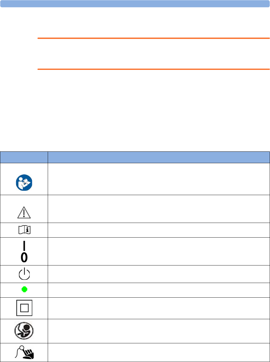
30 Specifications and Standards Compliance
322
Cardiac Pacemakers and Electrical Stimulators
WARNING
The fetal/maternal monitors are not intended for use for ECG measurements on patients connected
to external electrical stimulator, or with cardiac pacemakers.
Fast Transients/Bursts
The equipment will return to the previous operating mode within 10 seconds without loss of any
stored data.
Symbols on the System
These symbols can appear on the monitor and its associated equipment and packaging.
Symbol Description
This safety symbol indicates that you have to consult the Instructions for Use (this document),
and particularly any warning messages. The symbol can be also printed out black and white.
This symbol indicates that you have to consult the Instructions for Use (this document).
This symbol indicates that you should consult the Instructions for Use (this document).
Power-On/Off Switch - FM20/FM30 without Battery Option
Power-On/StandBy button - FM40/FM50 and FM20/30 with Battery Option
Power-On LED
Electrical Class II equipment, in which the protection against electric shock relies on double or
reinforced insulation (FM20/FM30)
Fetal Sensor Socket symbol
SpO2 Socket symbol
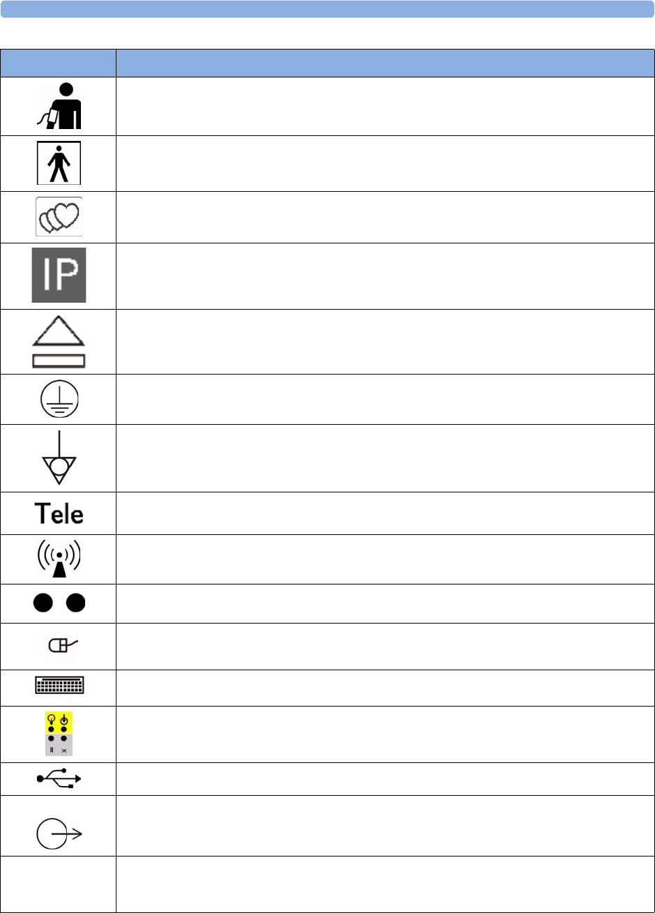
30 Specifications and Standards Compliance
323
Noninvasive Blood Pressure Socket symbol
Type BF
Symbol indicating the monitor has the triplets option
Symbol indicating the monitor is capable of intrapartum monitoring
Button to open paper drawer/paper eject. (FM40/FM50)
Protective earth terminal (FM40/FM50)
Equipotential grounding point (FM40/FM50)
Socket for connecting Avalon CTS interface cable M2732-60001 or Avalon CL interface cable
(with black connector, FM40/FM50)
Symbol indication for non-ionizing radiation
Connection direction indicator FM20/FM30 with battery option
Mouse connection indicator (optional)
Keyboard connection indicator (optional)
Serial/MIB connector (optional)
USB interface (optional)
Video Analog interface indicator for connection to any analog video display (VGA resolution) FM40/
FM50
IP 67 Ingress Protection code according to IEC 60529. The IUP/ECG patient module (M2738A) is
rated IP 67 (protection against dust, access to hazardous parts, and the effects of continuous
immersion in water to a depth of 0.5 meter for 30 minutes)
Symbol Description
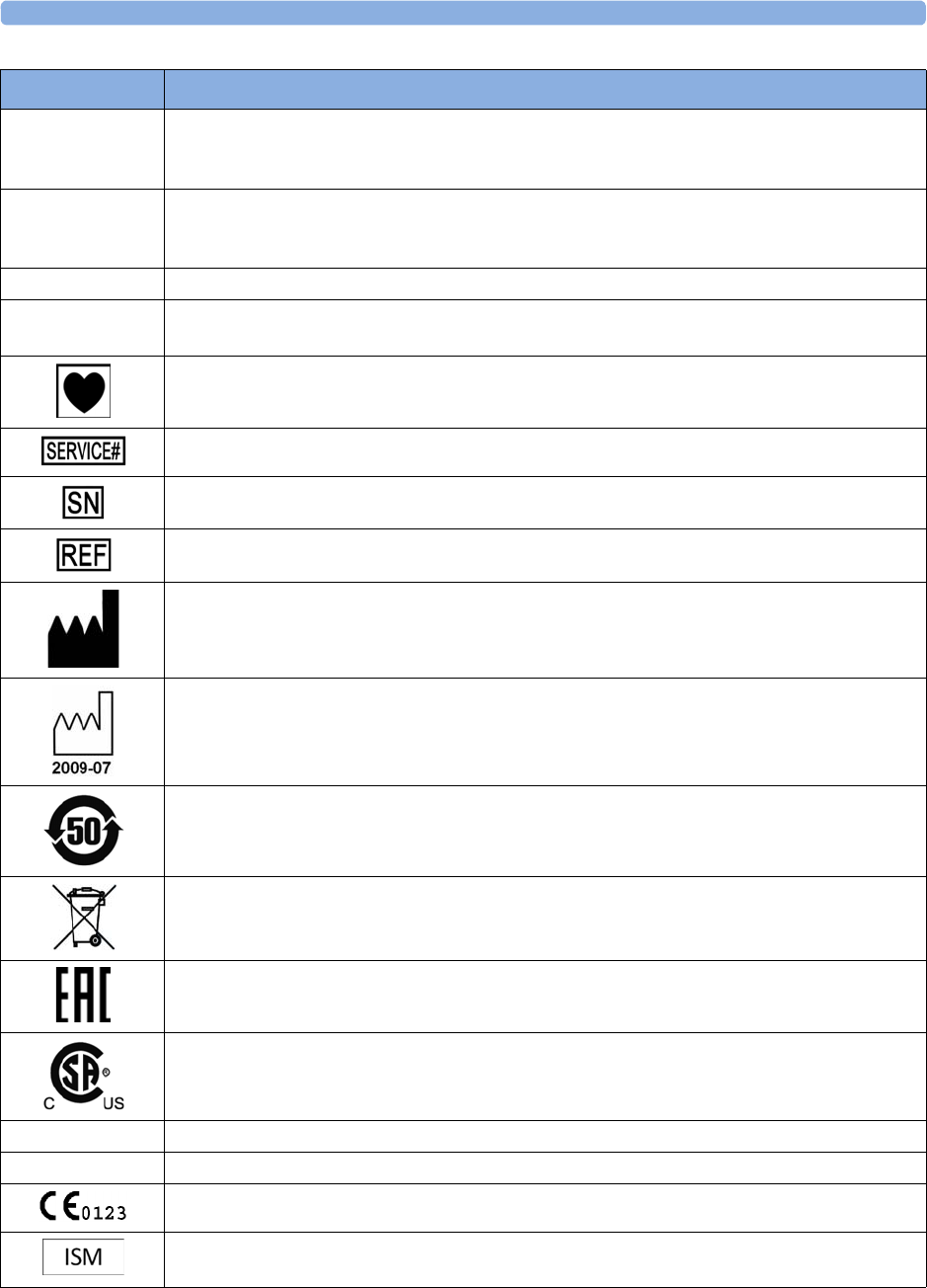
30 Specifications and Standards Compliance
324
IP 68 Ingress Protection code according to IEC 60529. All transducers (excluding M2738A) are rated
IP 68 (protection against dust, access to hazardous parts, and the effects of continuous
immersion in water to a depth of 1.0 meter for five hours)
IP X1 Ingress Protection code according to IEC 60529. The monitors and interface cable for the
Avalon CTS (M2731-60001/M2732-60001) are rated IP X1 (protection against water dripping
vertically only)
IP 31 Ingress Protection code according to IEC 60529 (protection against condensation only)
IP 21 Ingress Protection code according to IEC 60529 (protection against ingress of water when the
water is dripping vertically)
Type CF equipment, not defibrillation proof
Indicates location of service number
Indicates location of serial number
Indicates location of catalog number
Indicates location of the date of manufacture and/or name and address of manufacturer
Identifies year and month of manufacture
China RoHS
Symbol indicating separate collection for waste electrical and electronic equipment
EAC mark
CSA US mark
FCC ID Federal Communications Commission: FCC ID xxxx
CMIIT ID Chinese Radio marking: CMIIT ID (China Ministry of Industry and Information Technology)
CE marking accompanied by the Notified Body number 0123
Industrial, Scientific, & Medical radio frequency band (Avalon CL frequency band used e.g. in the
EU)
Symbol Description
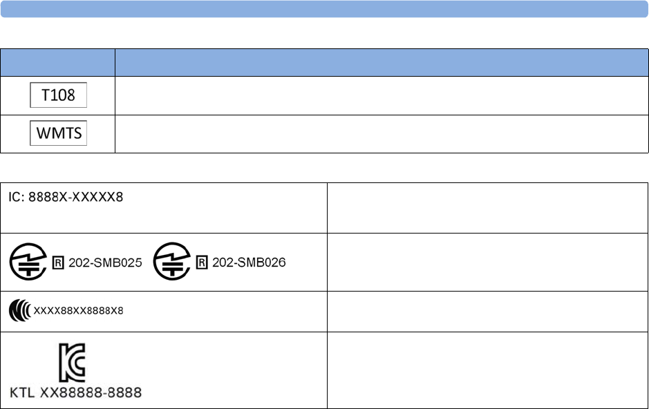
30 Specifications and Standards Compliance
325
Association Of Radio Industries And Businesses T108 (Avalon CL frequency band used e.g. in
Japan)
Wireless Medical Telemetry Service (Avalon CL frequency band used e.g. in North America)
Symbol Description
IC-ID (Industry Canada ID)
One IC-ID labeling for each built in radio: OBR, SRR
Japanese Radio marking: Radio mark + [R]-symbol +
ID
Taiwan Radio Label (NCC Logo) + ID
Korea radio mark: KC logo, KCC ID number, and
Conformity assessment information

30 Specifications and Standards Compliance
326

31
327
31Default Settings Appendix
This appendix documents the most important default settings of your fetal monitor and the Avalon CL
Base Station with the cableless transducers as they are delivered from the factory. For a comprehensive
list and explanation of default settings see the Configuration Guide supplied with your fetal monitor.
The monitor's default settings can be permanently changed in Configuration Mode.
Alarm and Measurement Default Settings
Alarm Defaults Settings
Alarm Settings Choice Default
Alarm Mode INOP only
,
All INOP only
(international)
All
(USA/CAN)
Alarm Volume
0..10 5
Alarms Off 1 min
,
2 min
,
3 min
,
Infinite 2 min
Alarm Text Standard
/
Enhanced Standard
Visual Latching Red & Yellow
/
Red Only
/
Off Red & Yellow
Audible Latching Red & Yellow
/
Red Only
/
Off Red & Yellow
Alarm Sounds Traditional
/
ISO Traditional
Alarm Low
0..10 4
Fetal / Maternal Defaults Settings (International)
FHR
,
dFHR
,
aFHR
Alarms On/Off Default
On
Default Color for FHR Numeric (for all
FHR numerics)
Orange
Toco
,
aToco
Default color for Toco numeric
Green
IUP
Default IUP Scale Unit
mmHg
Default color for IUP numeric
Green
HR
,
aHR
Measurement Default Color for MECG Numeric
Red

31 Default Settings Appendix
328
Coincidence Default Settings
NBP Default Settings
Fetal / Maternal Defaults Settings (US/CAN)
FHR
,
dFHR
,
aFHR
Alarms On/Off Default
On
Default Color for FHR Numeric:
FHR1
,
dFHR1
,
aFHR1
FHR2
,
dFHR2
,
aFHR2
FHR3
,
dFHR3
,
aFHR3
Red
Blue
Green
Toco
,
aToco
Default color for Toco numeric
Green
(Toco)
Yellow
(aToco)
IUP
Default IUP Scale Unit
mmHg
Default color for IUP numeric
White
HR
,
aHR
Measurement Default Color for MECG Numeric
Red
Coincidence Default Settings
Coincidence Tone immediately
Factory Default Settings
Mode Manual
Repeat Time 15 min
Alarms from Sys.
(International)
Sys&Dia&Mean
(USA/CAN)
NBP Sys/Dia only Yes
(International)
No
(USA/CAN)
Low Limit
90/50 (60)
High Limit
160/90 (110)
VP Pressure
60 mmHg
Done Tone Off
Veni Puncture
n/a
Start Time Synchronized
NBP On
Alarms On
Color Red
Reference Auscultatory

31 Default Settings Appendix
329
CL NBP Default Settings
SpO2 Default Settings
NBP Settings Factory Defaults
Mode Auto
Repeat Time 10 min
NBP On
VP Pressure 60 mmHg
Reference Auscultatory
Unit mmHg
Done Tone Off
Start Time Synchronized
Aging Time 10 min
Color Red
SpO2 Factory Default Settings
Desat Limit
80
Low Limit
90
High Limit
100
Desat Delay
20 seconds
Low Alarm Delay
10 seconds
High Alarm Delay
10 seconds
Average
10 seconds
NBP Alarm Suppr. On
Alarms On
Color Cyan
Pulse Default Settings
Pulse (SpO) On
High Limit
120 bpm
Low Limit
50 bpm
ExtrBrady
Bradycardia: Difference to Low Limit 20 bpm
Brady Clamp
40 bpm
ExtrTachy
Tachycardia: Difference to High Limit 20 bpm
Tachy Clamp
200 bpm

31 Default Settings Appendix
330
CL SpO2 Default Settings
Tympanic Temperature Default Settings
Manually Entered Values Default Settings
Recorder Default Settings
SpO2 Settings Factory Defaults
Repeat Time 15 min
Signal Quality On
NBP Alarm Suppr. On
Color Cyan
pTemp Settings Factory defaults
Adult
Low Limit
36°C (96.8°F)
High Limit
39°C (102.2°F)
Unit °C
Alarms On
Color White
Manual Entered Values Default Settings
Label Temp
(fixed)
Unit °C
Color White
Interval 1 h
Msmnt Off
Setting Choice Default
Recorder Speed
1, 2, or 3 cm/min 3 cm/min
Scale Type US
,
Internat'l US
Trace Style FHR1 Thin
,
Medium
,
Thick
,
Extra Thick Thick
Trace Style FHR2 Medium
Trace Style FHR3 Extra Thick
Trace Style Toco Thick
Trace Style HR Thin
Wave Style ECG Thin
ECG Wave
printing choice
Separate
,
Overlap Separate

31 Default Settings Appendix
331
Notes Recording Along
,
Across Along
(International)
Across
(USA/CAN)
Change Rec Speed Monitoring
,
Config Config
Auto Start Off
,
On Off
Confirmed Stop Off
Bridge Paperout On
Paper Save Mode Off
(International)
On
(USA/CAN)
NST Autostart On
NST Autostop Off
Trace Separation Off
Separation Order Standard
,
Classic Standard
(International)
Classic
(USA/CAN)
Intensity
4 (medium) n/a
Cal. Offset
5 n/a
Setting Choice Default

31 Default Settings Appendix
332

333
1Index
A
accessories 275, 276, 277, 278, 279, 280, 285
Avalon CL base station 275
cl NBP Pod accessories 280
cl SpO2 Pod accessories 284
fetal accessories 276
electrode patch 276
fetal recorder accessories 285
latex information 275
MECG accessories 277
noninvasive blood pressure
accessories 278, 279
adult cuffs 279
multi-patient comfort cuff kits 278
reusable cuffs 278
single-hose disposable cuffs 279
SpO2 accessories 280
Philips sensors (disposable) 280
Philips sensors (reusable) 280
transducer accessories 276
tympanic temperature 285
tympanic temperature accessories 285
ACOG technical bulletin 60
actions after monitoring 70
adjusting display 49
admitting a patient 147, 148
auto free 26
editing information 148
OB TraceVue/IntelliSpace
Perinatal 149
quick admit 148
aging numerics 238
alarms 117, 119, 120, 121, 122, 123, 124, 126,
128, 129, 197, 198, 240, 246, 298, 304, 305,
327
acknowledging alarms 121
active alarms 117
alarm behavior at on/off 128
alarm latching 127
alarm limit delay 300
alarm reminder 122
alarm standards 119
audible alarm indicators 119
changing alarm delays 198
high priority alarms 117
latching alarms 126, 127
latching alarm behavior 127
pausing alarms 122
red alarms 117
restarting paused alarms 123
reviewing alarms 126
reviewing alarms window 126
standard philips alarms 120
yellow alarms 117
applying the fetal & maternal pod 100
artifact suppression 204
artifact suppression and fetal
arrhythmia 204
explanation of artifact suppression 204
switching on and off artifact
suppression 204
B
baseline measurement 185, 192, 208
Battery Option 109
using batteries 109
belt actions 50, 51, 52
belt fastening 50, 51
belt fixing button 51
C
cableless monitoring 73
Avalon CL 73
cableless transducers 84
assignment 99
audio signal 87
cl belt clip 88
connector cap 85
LED indication 86
radio range 87
cl pods 92
audio signal 93
battery status LED 93
configuration cableless system 75
important considerations 167
LED indication 86
paging patients 93
prompts 96
Tele Info window 94
Telemetry 95
Underwater monitoring 108
calibration 241, 268
calibrating noninvasive blood
pressure 268
cautions 9
changing FHR alarm delays 198
changing FHR alarm limits 197
CL Fetal & Maternal Pod 89
applying 100
CL Wide Range Pod 91
cleaning monitor actions 261, 262, 263, 273
cleaning method 262
cleaning monitoring accessories 263
general cleaning requirements 261
infection control 261
printhead cleaning 273
configuration mode 44
configuring alarm tone 119
confirming fetal life 10, 166, 183, 191
cross-channel verification 10, 183, 191, 222
CCV and triplets 191
CCV and twins 183
coincidence examples 162
comparing FHR with MHR 160
functionality 160
misidentification of heart rates 159
overview 161
recommended actions 164
D
data recovery 257
date from OB TraceVue/IntelliSpace
Perinatal System 47
date setting 47
Dawes/Redman 22
DECG 202, 205, 298
DECG INOPs 205
DECG specifications 298
DECG testing 205
DECG troubleshooting 205
default settings 298
alarm default settings 327
FHR default settings 298
IUP default settings 298
MECG default settings 298
noninvasive blood pressure default
settings 304
recorder factory default settings 308
SpO2 factory default settings 305
Toco default settings 298
user defaults 46
defibrillation precautions 225, 275, 321
demo mode 44
device classification 18
disabling touchscreen 44
discharging a patient 148
disinfecting 261, 262, 263
infection control 261
recommended substances 263

334
display 49, 238, 298
adjusting display 49
adjusting screen brightness 47
display noninvasive blood pressure 238
fetal display specifications 298
disposal of electronic waste 274
disposal of monitor 274
dyshemoglobins 244
intravascular dyshemoglobins 244
E
early systolic blood pressure 238
ECG 202, 222, 298
ECG specifications 298
electrical safety tests 312
electrical surgery precautions. See ESU 225,
244, 275, 321
electrodes 224
applying electrodes 224
EMC 313
electromagnetic compatibility 313
electromagnetic emissions 315
electromagnetic interference 314
how to reduce electromagnetic
interference 314
EMC and compliant accessories 313
EMC precautions 313
EMC standards 313
entering notes 42
ESU precautions 225, 275, 321
extension cable for SpO2 244
external monitoring 165, 184, 192, 208
external monitoring - Toco 208
external monitoring - triplets 192
external monitoring - twins 184
external monitoring - ultrasound 165
F
FAST 243
Fourier Artifact Suppression
Technology 243
fetal accessories 276
fetal arrhythmia 204
fetal demise 10
fetal display specifications 298
IUP - fetal display specifications 298
Toco - fetal display specifications 298
US - fetal display specifications 298
fetal heart rate alerting. See FHR 197
fetal heart rate. See FHR 165
fetal movement 170
fetal movement profile. See FMP 165
FHR 10, 166, 172, 183, 185, 191, 192, 197, 198,
222, 298
alerting 197
cross-channel verification 222
misidentification 10
trace separation 185, 192
FHR alarms 298
finder LED 36, 53, 183, 191
finding monitor revision 48
flexible nurse call 25, 32, 35
FMP 170, 171
FMP and twins 170
FMP statistics 171
functional arterial oxygen saturation 243
G
global settings 46
I
infection control 261
infection and sterilizing 261
INOPs 117, 121
CCV INOP
coincidence tone 24
disconnect INOPs 121
INOP alarms 117
red or yellow INOPs 24, 25
INOPs indicators 117
silencing INOPs 121
interference 313, 314
how to reduce interference 314
interference from RF equipment 313
internal monitoring 185, 199, 213
intrauterine pressure. See IUP 211
intravascular dyshemoglobins 244
intravascular dyshemoglobins effects on
(SpO2) 244
IUP 211, 213, 298
IUP specifications 298
M
mains power (AC) 71
disconnecting from mains power 71
maintenance 267, 268
maintenance schedule 267, 268
visual inspection 267
manual data entry 254
maternal ECG 204, 225, 227
electrode position 225
printing waveform 204, 227
viewing waveforms 225
maternal heart rate 221, 222
maternal heart rate and cross-channel
verification 222
maternal heart rate and priorities 221
maternal heart rate from MECG 222
sources of maternal heart rate 221
maternal HR 166, 221, 222, 224
Maternal HR from MECG 222
Maternal HR priorities 221
Maternal HR sources 221
maternal temperature 23
measurement settings 46
changing measurement settings 46
entering setup menu 46
measurements 45, 46, 295
setting up measurements 46
switching on and off measurements 45
MECG 204, 222, 224, 225, 227, 229, 231, 277,
298
accessories 277
alarm limits 300
connection illustration 222
default settings 298
electrodes 224
specifications 298
waveform printing 204, 227
MECG alarm limits 298
methemoglobin (SpO2) 244
monitor settings 10, 31, 47, 48, 49, 71, 257
changing monitor settings 47
major parts and keys 31
power on/off behavior 71
Standby 71
starting monitoring 168
switching on 48, 49
monitoring mode 44
monitoring triplets and FHR 191
monitoring twins and FHR 183
MR imaging and the SpO2 transducer 244
MRI precautions 225, 275, 321
N
NBP. See noninvasive blood pressure 235
NIBP. See noninvasive blood pressure 235
Noninvasive Blood Pressure (NBP) 228,
235, 236, 237, 238, 239, 240, 241, 242, 268,
278, 279, 304
automatic noninvasive blood pressure
repeat time 239
calibration interval 268
comfort cuff kits 278
factory defaults 304
how the measurement works 235
measurement 236, 239
limitations 236
methods 236
starting 239
stopping 239
NBP accessories 278
NBP adult cuffs 279
NBP automatic mode 239
NBP configurable measurement

335
sequence 25
NBP numerics 238
NBP pediatric cuffs 279
NBP performance specifications 304
NBP reusable cuffs 278
NBP single-hose disposable cuffs 279
NBP site inspection 237
NBP troubleshooting 242
NBP venous puncture 241
preparing to measure NBP 237
non-medical devices 312
non-medical devices in patient
vicinity 312
Non-Stress Test timer. See NST timer 152
NST Report
Trace Interpretation 153, 157
NST timer 151, 152
O
OB TraceVue 29, 30, 258
connection to OB TraceVue/
IntelliSpace Perinatal System 29, 30
LAN connection 258
operating modes 44
configuration mode 44
demo mode 44
monitoring mode 44
service mode 44
operating temperatures 321
oscillometric measurement method 235
P
Paging Patient 93
paper 60, 61, 62, 65, 272, 285
default recorder speed 60
loading paper 62, 65
paper out INOP 62
paper speed 60
changing 60
default 60
defaults 60
setting 60
paper, when to reload 62
recorder paper 285
removing paper 62, 65
storing paper 272
tearing off a trace 61
Paper Advance key 42
Paper-Out indication 62
passcode protection 44
patient alarms 129
Patient Demographics window 147
patient module 202, 222
paused alarms 122, 123
restarting paused alarms 123
performance specifications 295, 304, 305
noninvasive blood pressure
specifications 304
SpO2 specifications 305
physiological alarms 117
pop-up keys 96
power 71
disconnecting from 71
power failure 72
power on/ power off behavior 71
pulse 228
pulse from noninvasive blood
pressure 228
pulse rate 221
Q
QRS tone pitch 247
R
recorder 56, 72, 272, 273, 285, 308
factory defaults 308
paper storage 272
printhead cleaning 273
recorder paper 285
recorder specifications 308
recorder troubleshooting 72
recording elements 59
recording stored data 42
recovering traces 257
trace recovery printout 257
recycling 274
regulatory compliance 311
remote event marker 60
S
safety 268, 311
maintenance interval 268
safety information 13
safety standards 311
screen layouts 45
selftest 48, 49, 56, 128
sensor 243
disposable SpO2 sensors 243
selecting SpO2 sensors 243
separating FHR traces 185, 192
separating triplet traces 192
separating twin traces 185
service mode 44
settings 45, 46, 47
active settings 45
changing settings 47
factory default settings 46
global settings 46
monitor settings 47
user default settings 46
short range radio 92, 317, 320
signal loss delay 198
signal quality 70, 246
signal quality during monitoring 70
signal quality of SpO2 246
silencing alarms 121
specifications 289, 295, 298, 308
built-in recorder specifications 308
DECG specifications 298
ECG specifications 298
IUP specifications 298
measurement specifications 295
MECG specifications 298
performance specifications 295, 298
Toco specifications 298
transducer specifications 289
US specifications 298
SpO2 243, 244, 246, 280, 305
accessories 280
alarm specifications 305
connecting the cables 244
disposable sensors 243
factory defaults 305
FAST technology 243
performance specifications 305
Philips sensors (disposable) 280
Philips sensors (reusable) 280
signal quality 246
tone modulation 247
SpO2 alarms 246, 305
standards 311, 313
EMC standards 313
safety standards 311
standards compliance 311
Standby 42
starting monitoring 48
sterilizing 261, 265
infection control 261
storage temperatures 321
stored data recording 42
suppressing artifacts 204
suspended alarm 123
suspicious SpO2 reading 246
switching on and off 171
switching on and off alarms 124
switching on monitor 48, 49
switching on recorder 56
symbols on the system 322
T
technical alarm messages. See INOPs 132
temperatures 321
operating temperatures 321
storage temperatures 321

336
testing 128, 205, 229, 312
DECG testing 205
MECG testing 229
safety testing 312
testing alarms 128
time 47
setting time 47
time from OB TraceVue/IntelliSpace
Perinatal System 47
Toco 202, 207, 208, 210, 224, 298
default Toco settings 298
testing a Toco transducer 210
Toco baseline 208
Toco display specifications 298
Toco monitoring 207
Toco sensitivity 208
Toco specifications 298
Toco MP transducer 207, 221
Toco+ transducer 207
tone modulation (SpO2) 247
touch tone volume 47
touchscreen operation 38, 44
trace actions 61, 257, 258
tearing off traces 61
trace recovery on OB TraceVue/
IntelliSpace Perinatal System 258
trace recovery on paper 257
transducer 36, 51, 53, 173, 183, 191, 207, 210,
289
connecting transducer to monitor 53
fixing transducer to belt 51
repositioning transducers 53
Toco transducer 207
Toco+ transducer 207
transducer belt clip 51
transducer specifications 289
transducer testing 173, 210
Toco 210
ultrasound 173
triplets 191, 192, 193, 194, 196
cross-channel verification 191
external monitoring 192
importance of monitoring MHR 191
monitoring triplets 191
offsetting baselines 192
troubleshooting 72, 172, 189, 196, 205, 208,
214, 227, 242
DECG 205
FHR 172
IUP 214
MECG 227
twins 170, 183, 184, 185, 186, 187, 189
cross-channel verification 183
external monitoring 184
importance of monitoring MHR 183
invasive monitoring 185
monitoring FHR 183
monitoring twins 183
offsetting baselines 185
twins and FMP 170
Tympanic Temperature 249
body reference sites 254
display and controls 250
manual data entry 254
status screens 251
taking temperature 252
tympanic temperature accessories 285
U
ultrasound 165, 168, 173, 298
applying gel 168
testing a transducer 173
ultrasound display specifications 298
ultrasound monitoring 165
ultrasound specifications 298
understanding screens 45
USB 25
using the adapter cable 202
uterine activity 202, 207, 208, 211, 213, 214,
224
external monitoring 207
internal monitoring 211
monitoring uterine activity 202, 208, 211,
213, 224
troubleshooting uterine activity 208, 214
V
velcro belt 52
venous puncture 241
visual alarm indicators 119
volume 47, 120
alarm volume 120
IUP, zeroing 213
touch tone volume 47
W
warnings 9

Part Number 453564659391
Published in Germany 09/16
*453564659391*