Philips Medical Systems North America ST80IAIM Advanced Interface Module User Manual
Philips Medical Systems North America Co. Advanced Interface Module
UserManual.wiki
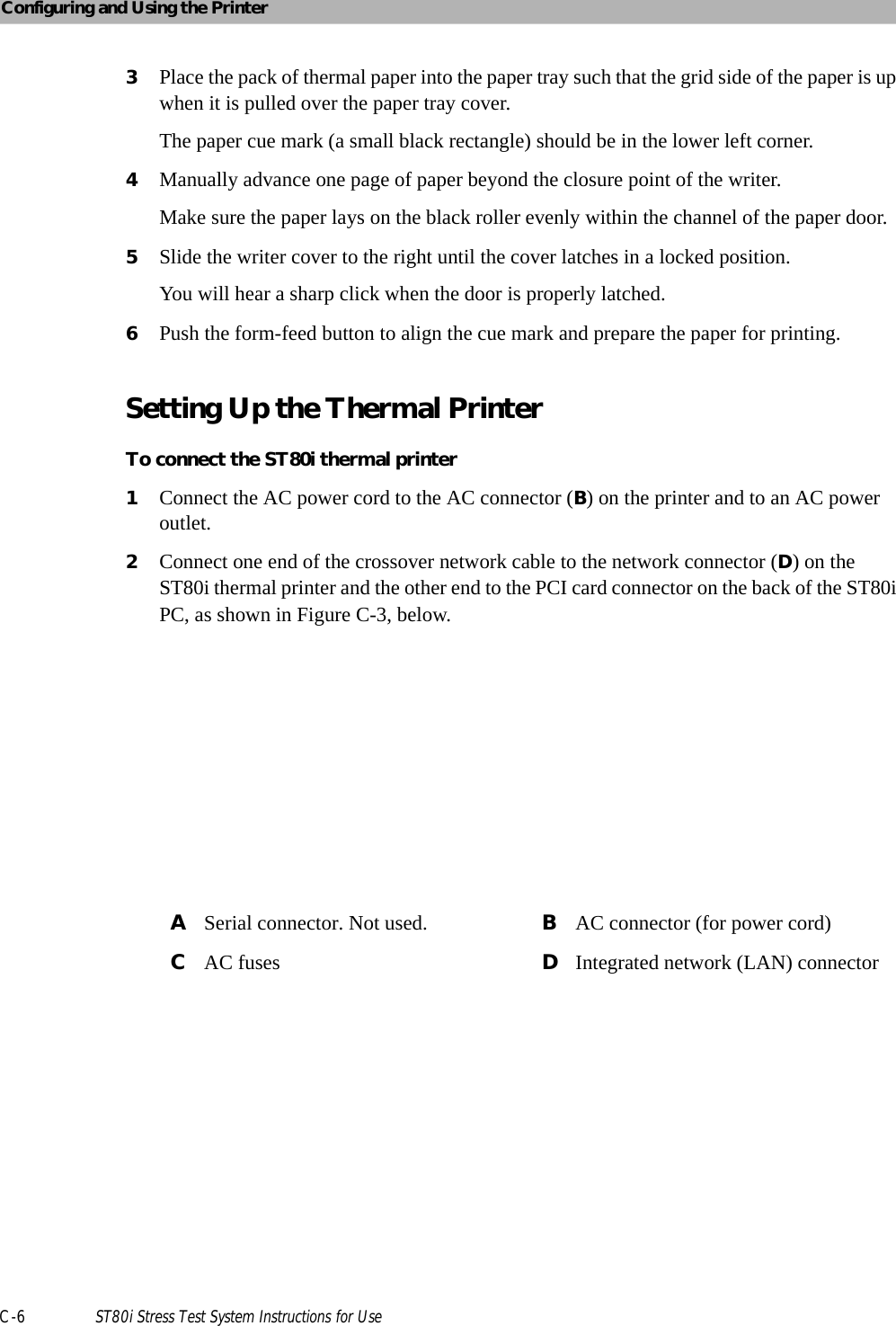
>
Philips Medical Systems North America
>
ST80IAIM User Manual
PQC-ST80iAIM_User manual_Rev1
Navigation menu
Upload a User Manual
Namespaces
Wiki Guide
HTML
PDF
Info
Views
User Manual
Discussion / Help
Navigation
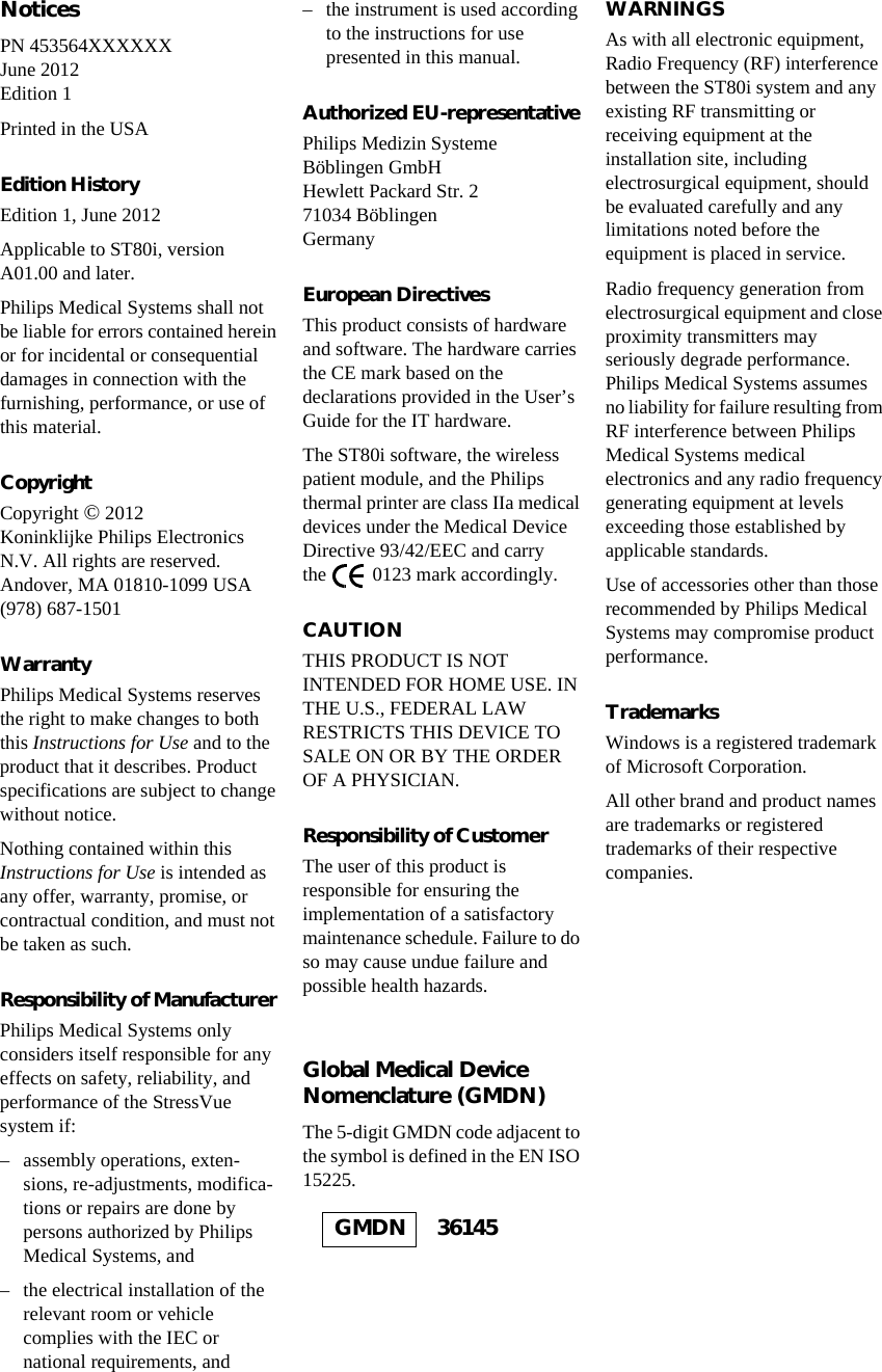

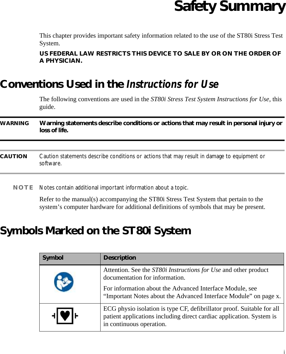
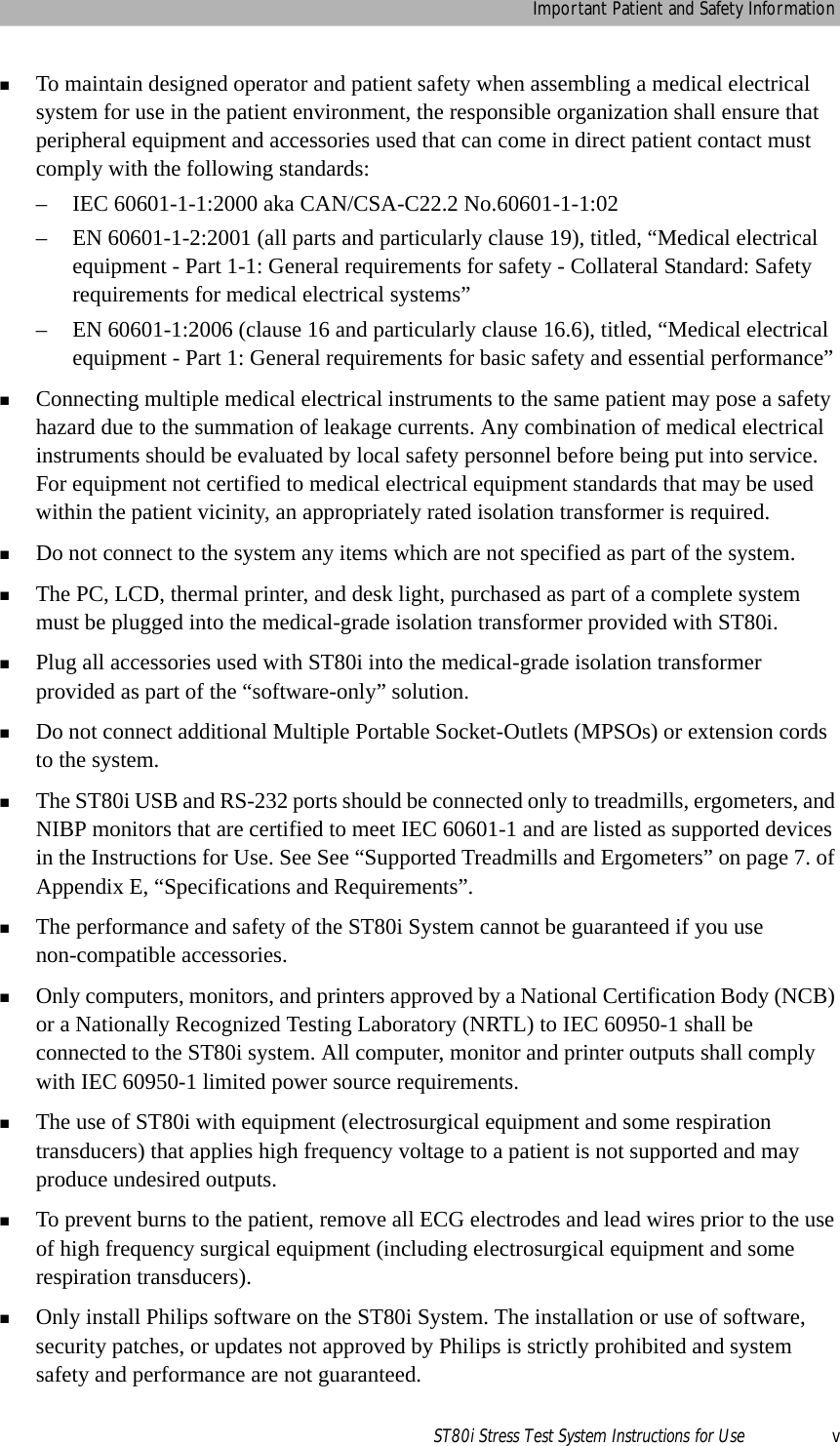
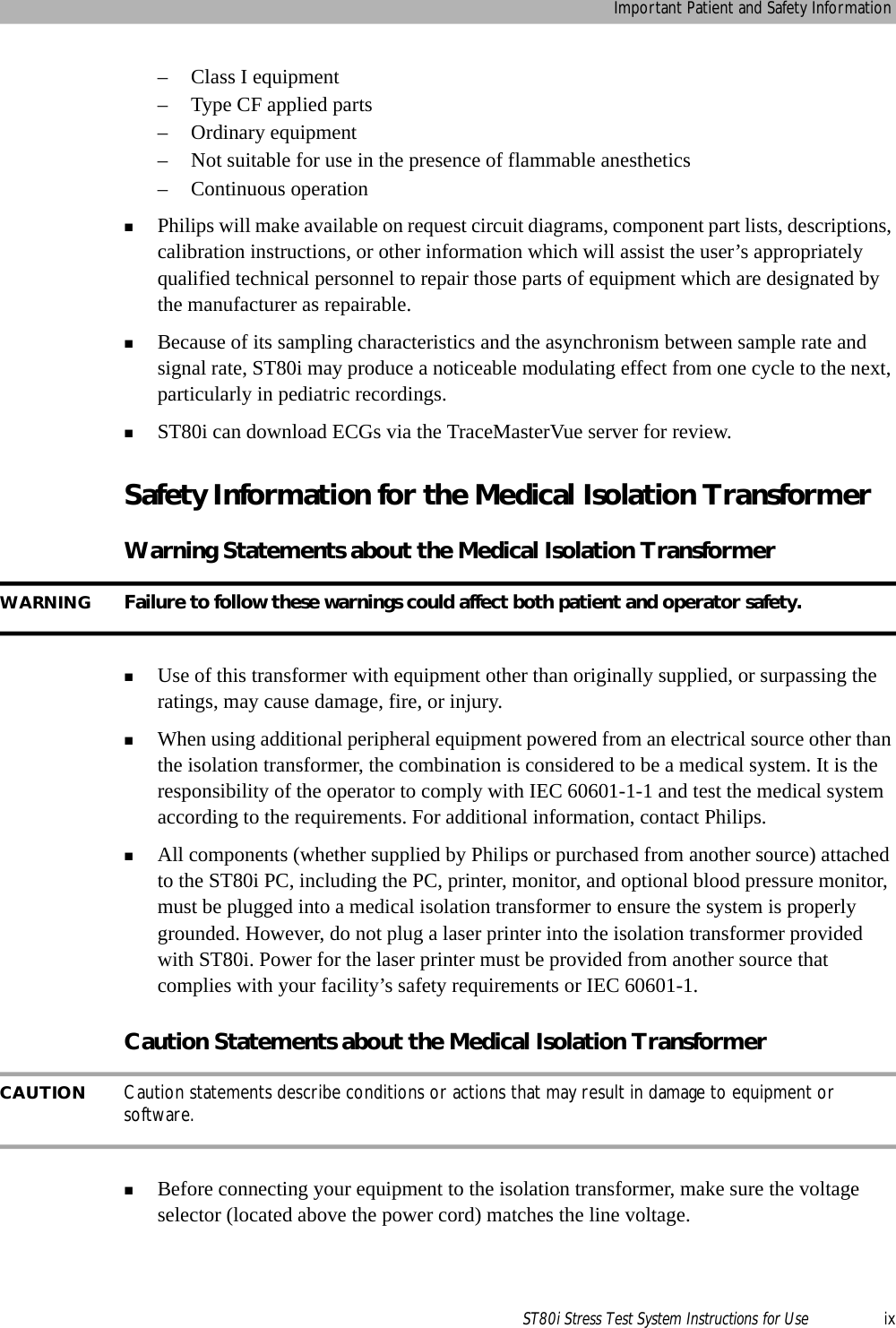
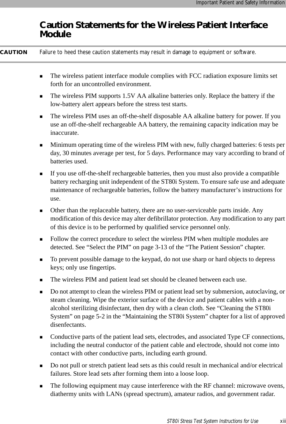
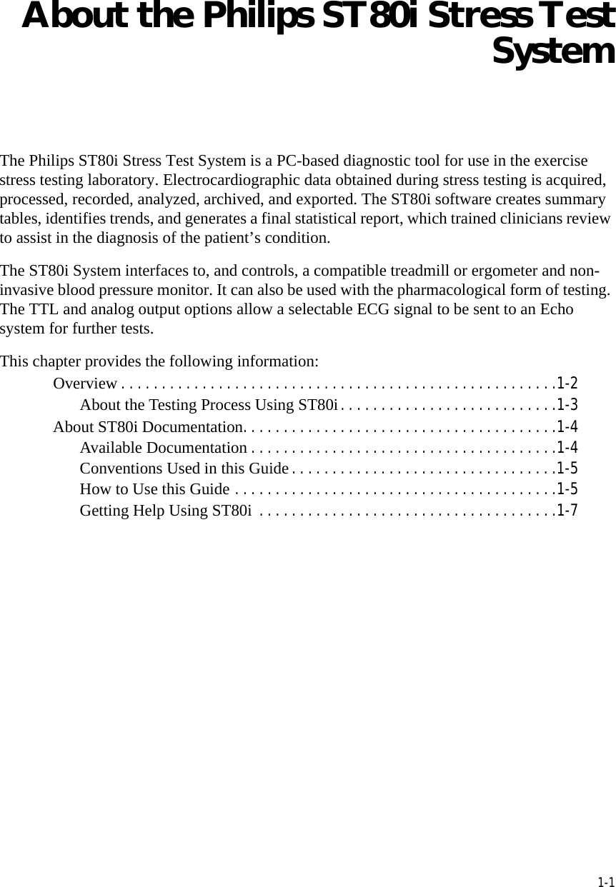
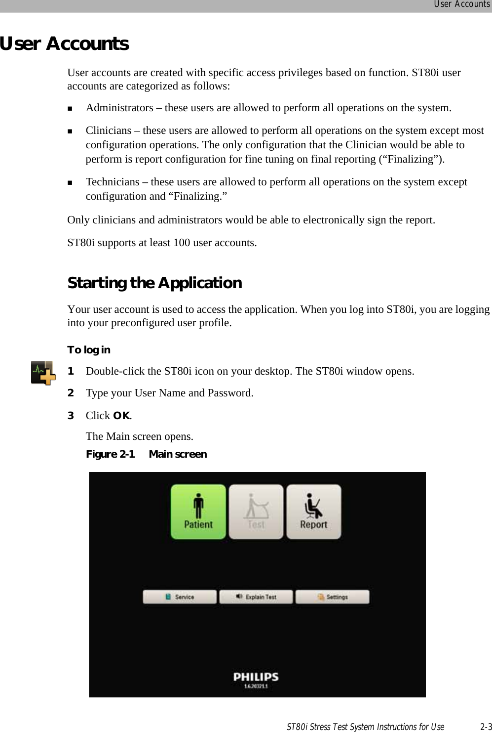
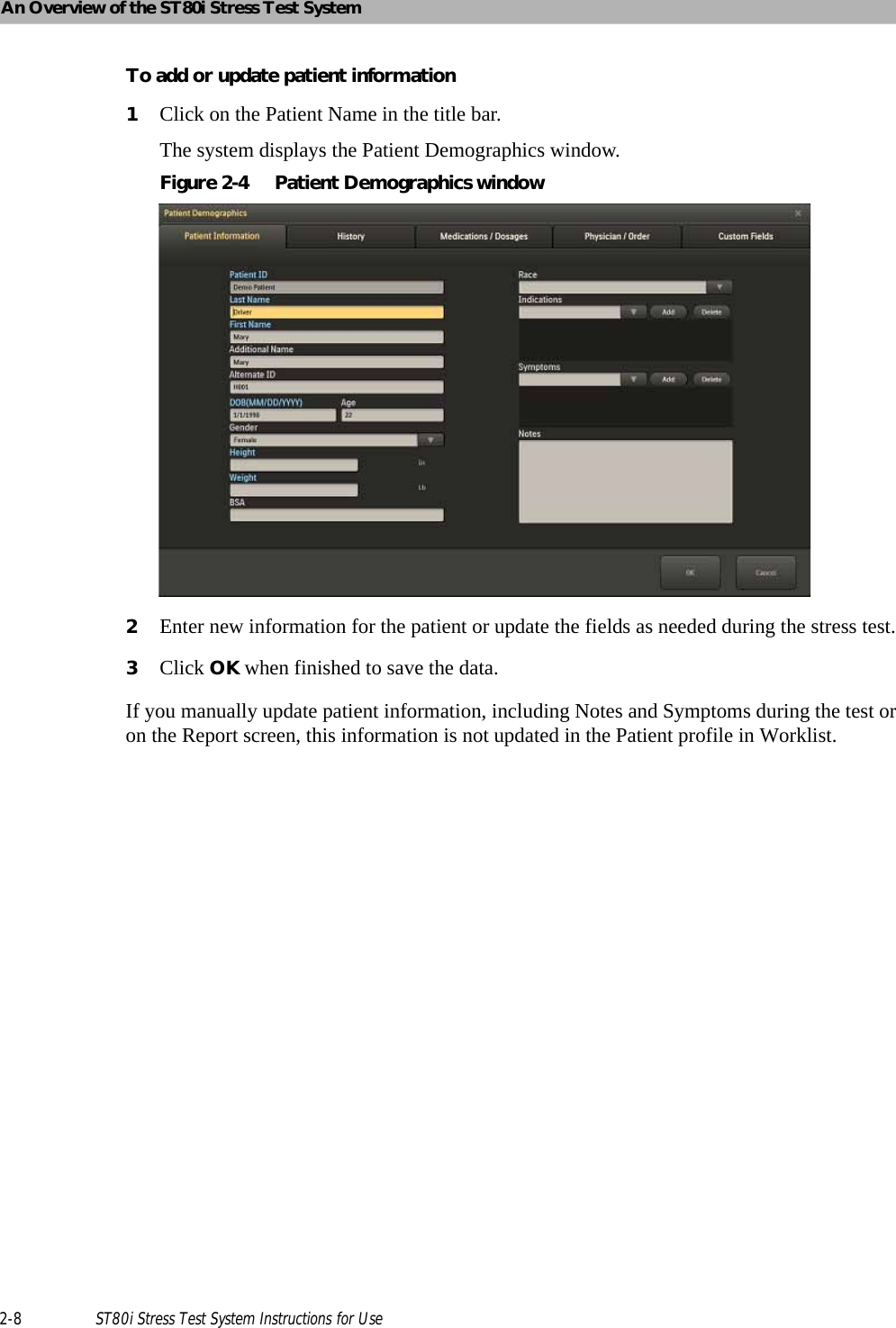
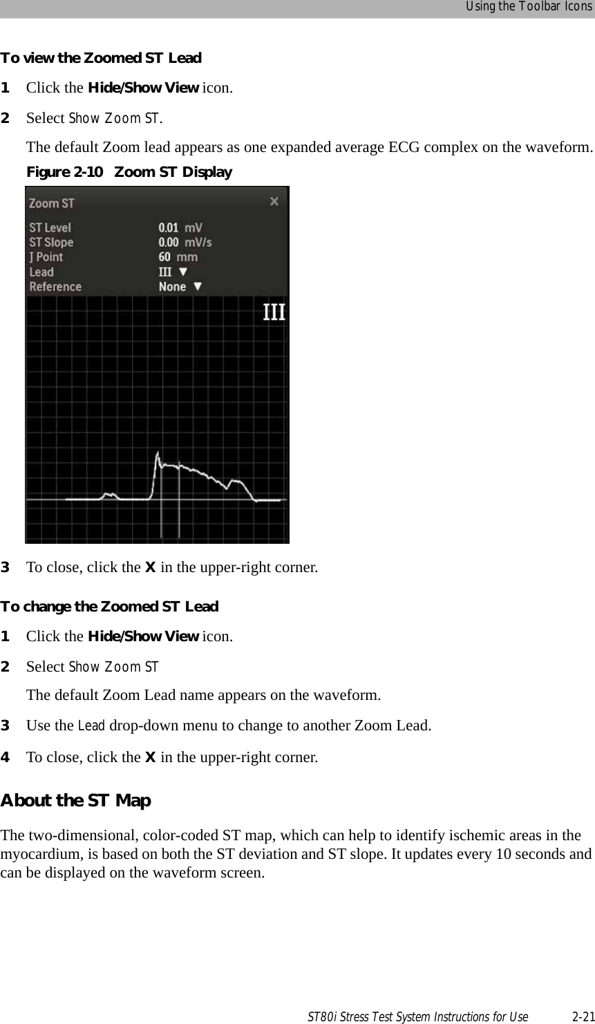
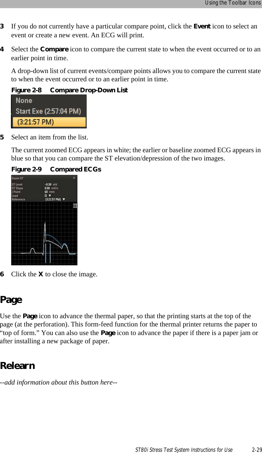
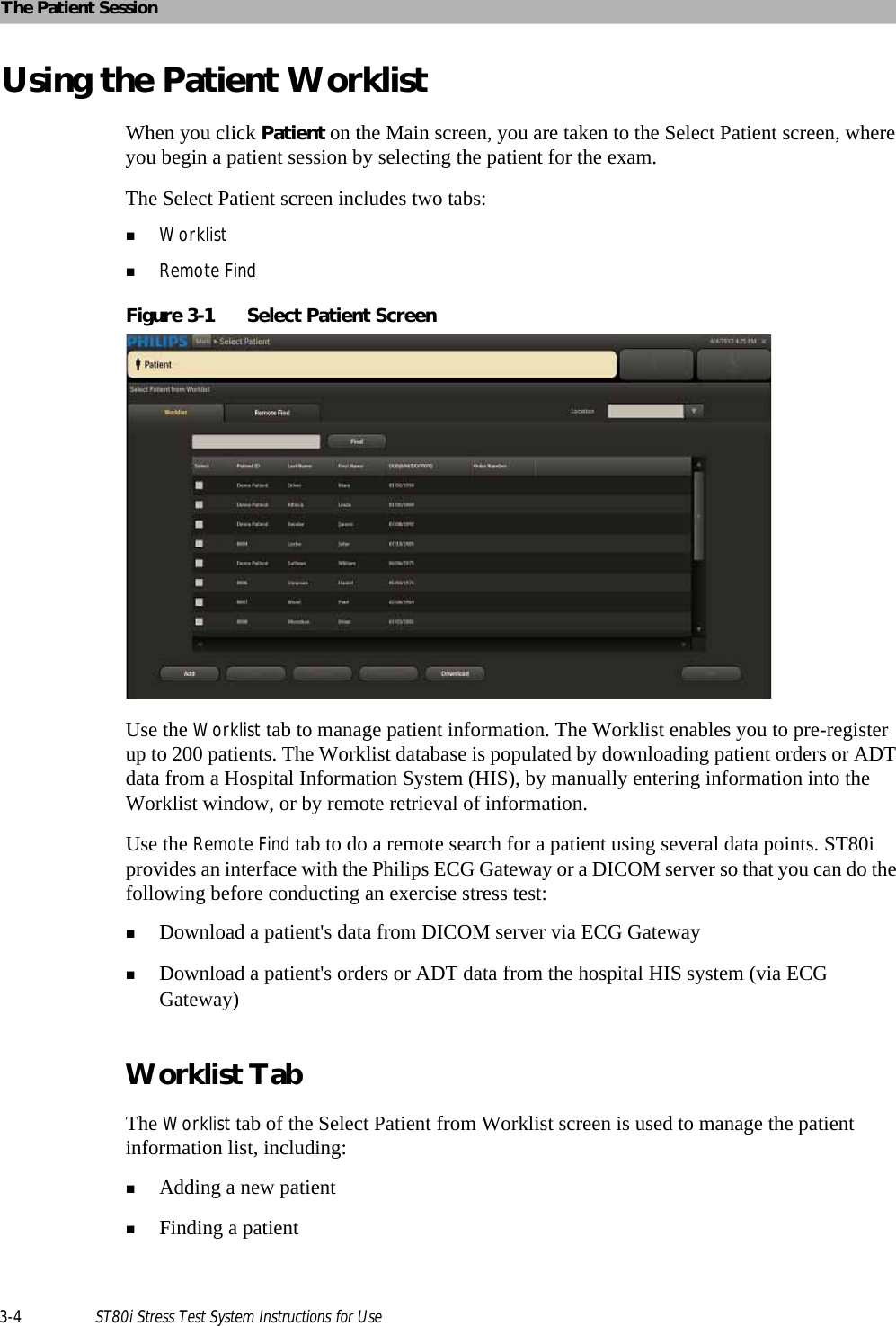
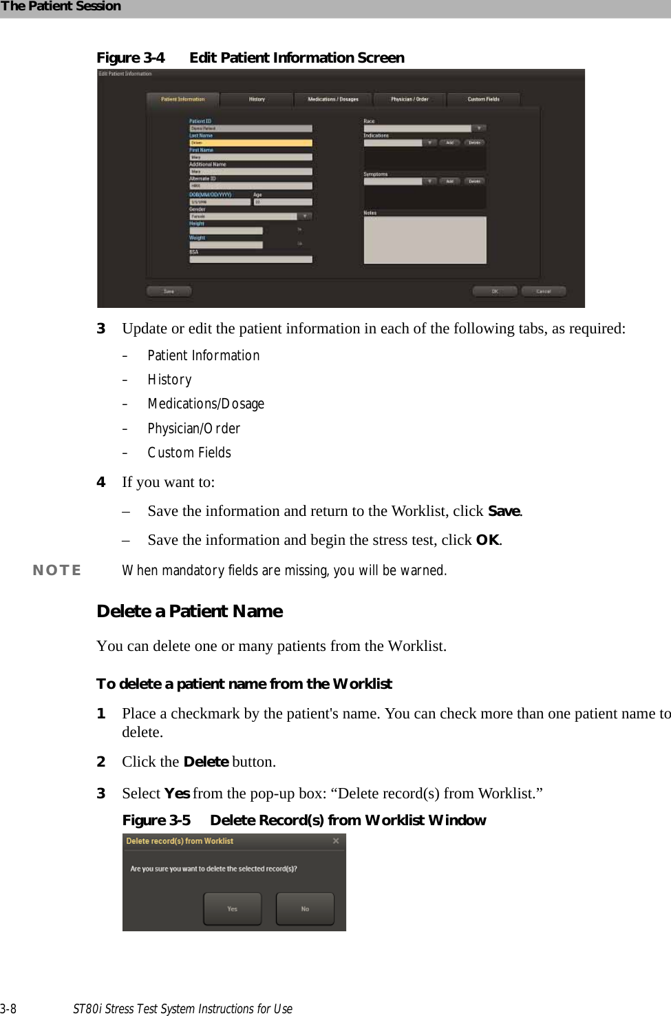
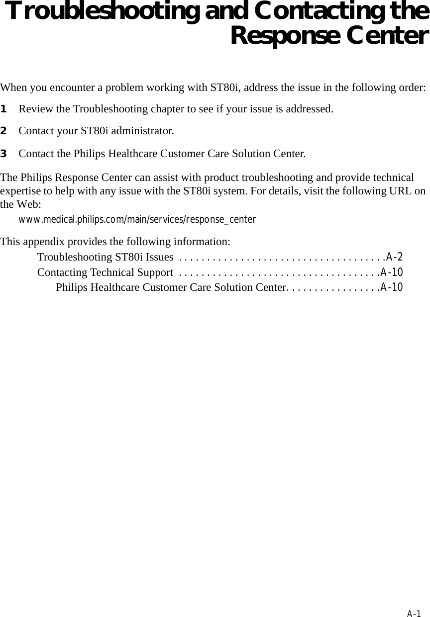
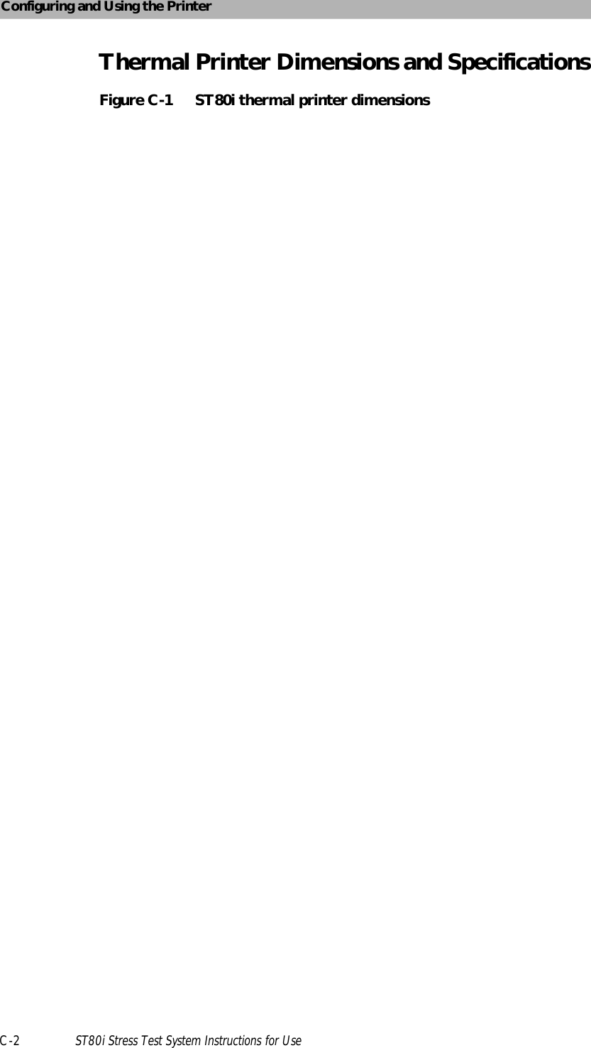
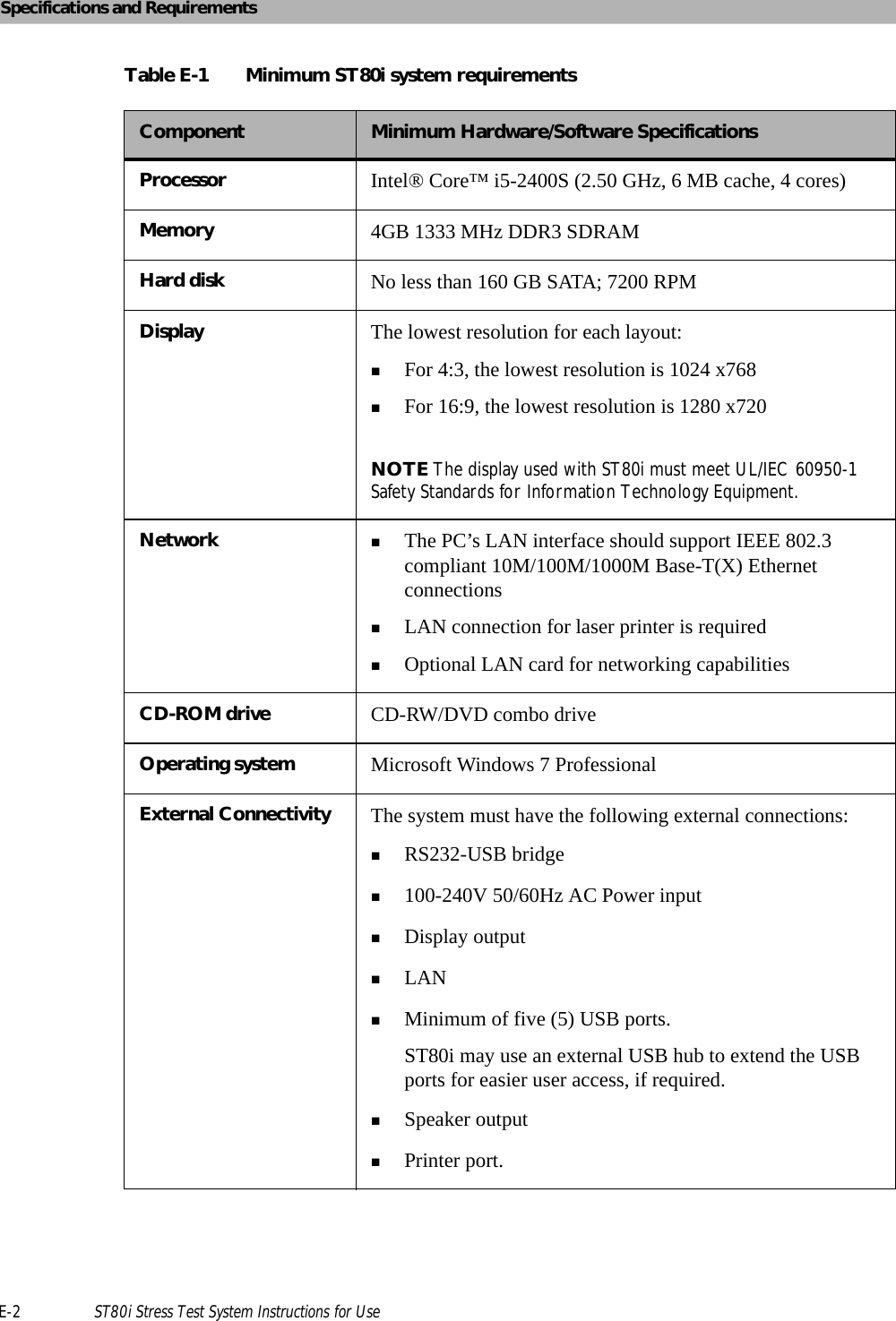
![ST80i Test ScreenST80i Stress Test System Instructions for Use 2-7Title BarAt any time during the Pre Exercise or Report phases of the patient session, you can use the title bar to manually input and edit patient information with data that will be centrally stored in the stress database. The Title Bar includes the features shown and described below.Figure 2-3 TitleBarTable 2-2 Title Bar FeaturesBProcedure Bar - used to control the exercise stress test process; shows exercise stage; selected patient interface device; protocol; BP, ECG Print and Rhythm Print buttons; and stage timeCToolbar - displays the Toolbar icons that provide quick access to frequently used commands throughout the exercise stress testDWaveform Screen - provides real-time ECG waveforms during the exercise stress testESide Panel - provides real-time updates during the stress test as well as target heart rate, NIBP and SpO2, and exercise equipment data (speed, grade, stop & start)Feature DescriptionANavigation Keys [Main Test] - Click Main to leave exercise test and return to Main screenBPatient Name - Click the patient name to update patient information and add notes on the Patient Information tab of the Patient Demographics screenCPatient's Date of BirthDPatient IDELED indicators for the RF Transmitter and PIM battery statusFCurrent Date and TimeFeature DescriptionAB C DEF](https://usermanual.wiki/Philips-Medical-Systems-North-America/ST80IAIM/User-Guide-1723687-Page-45.png)
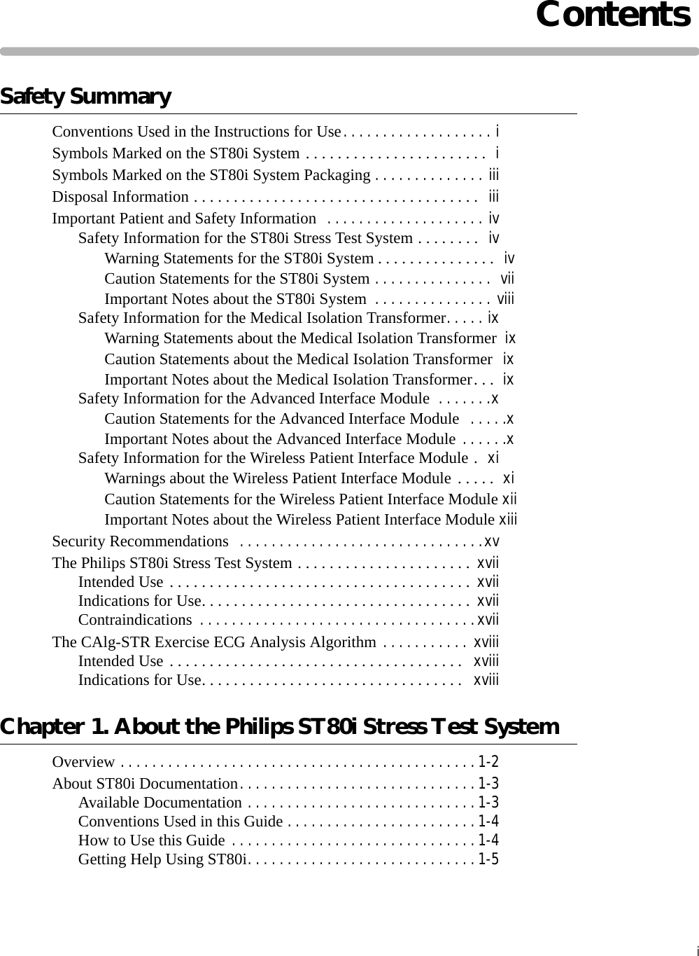
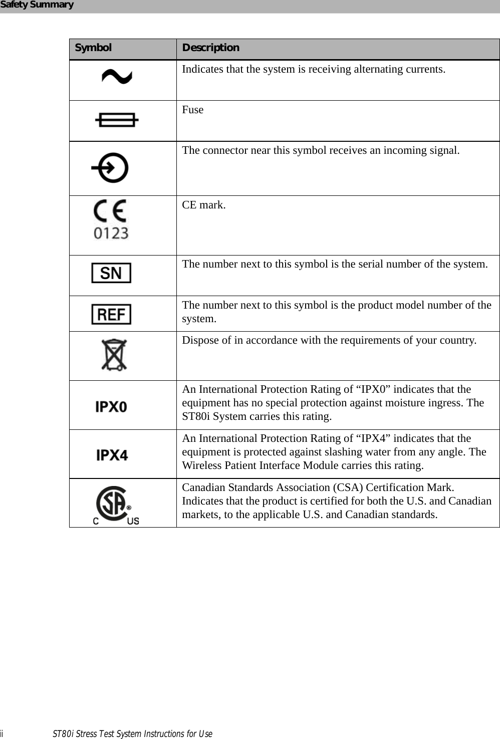
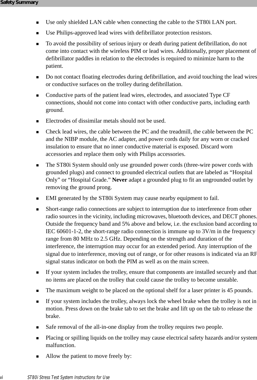
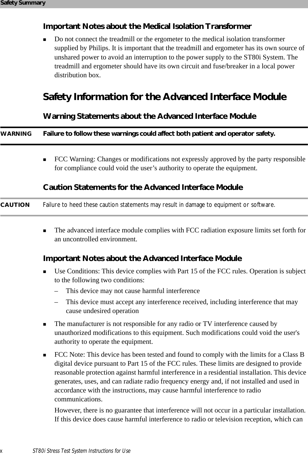
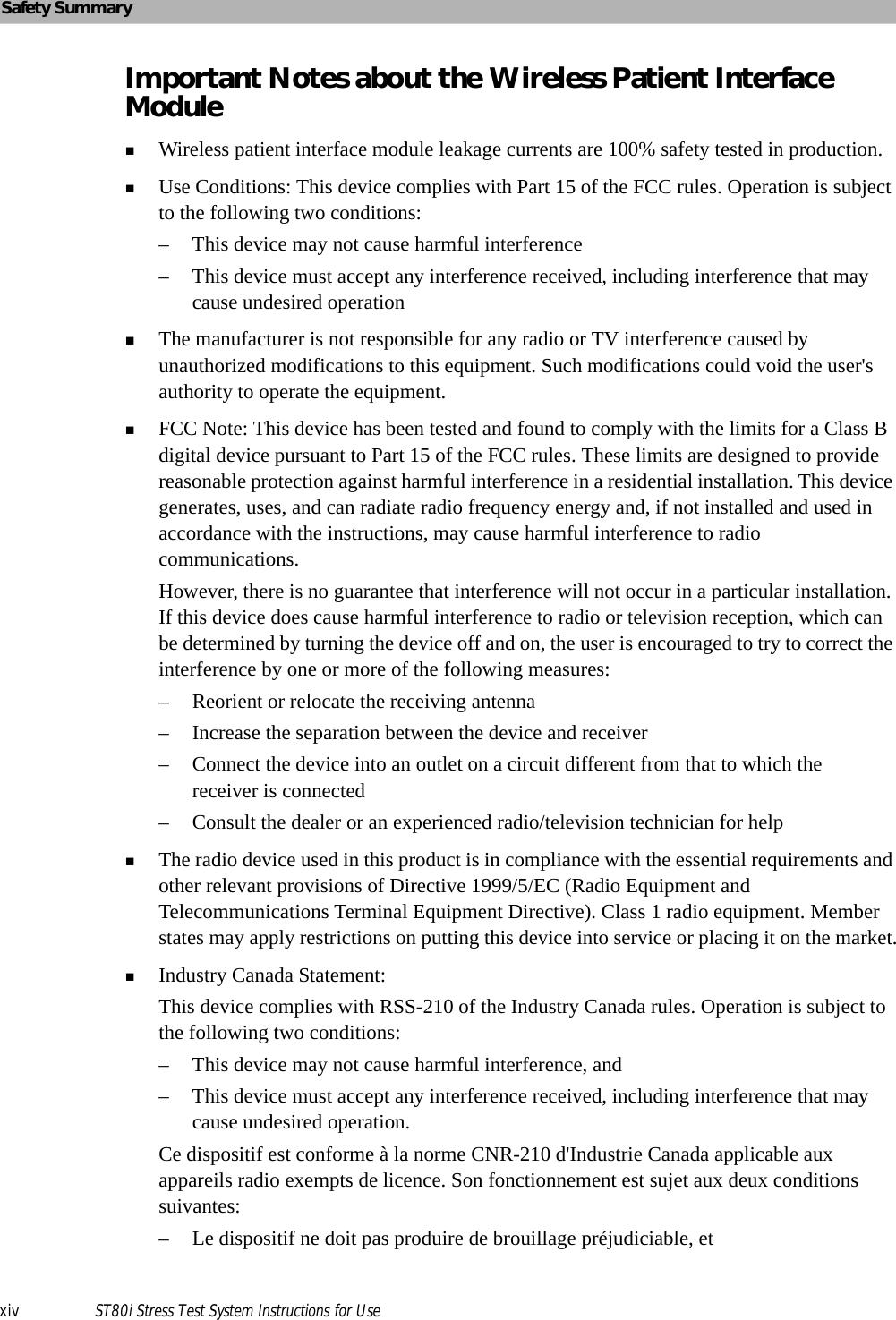
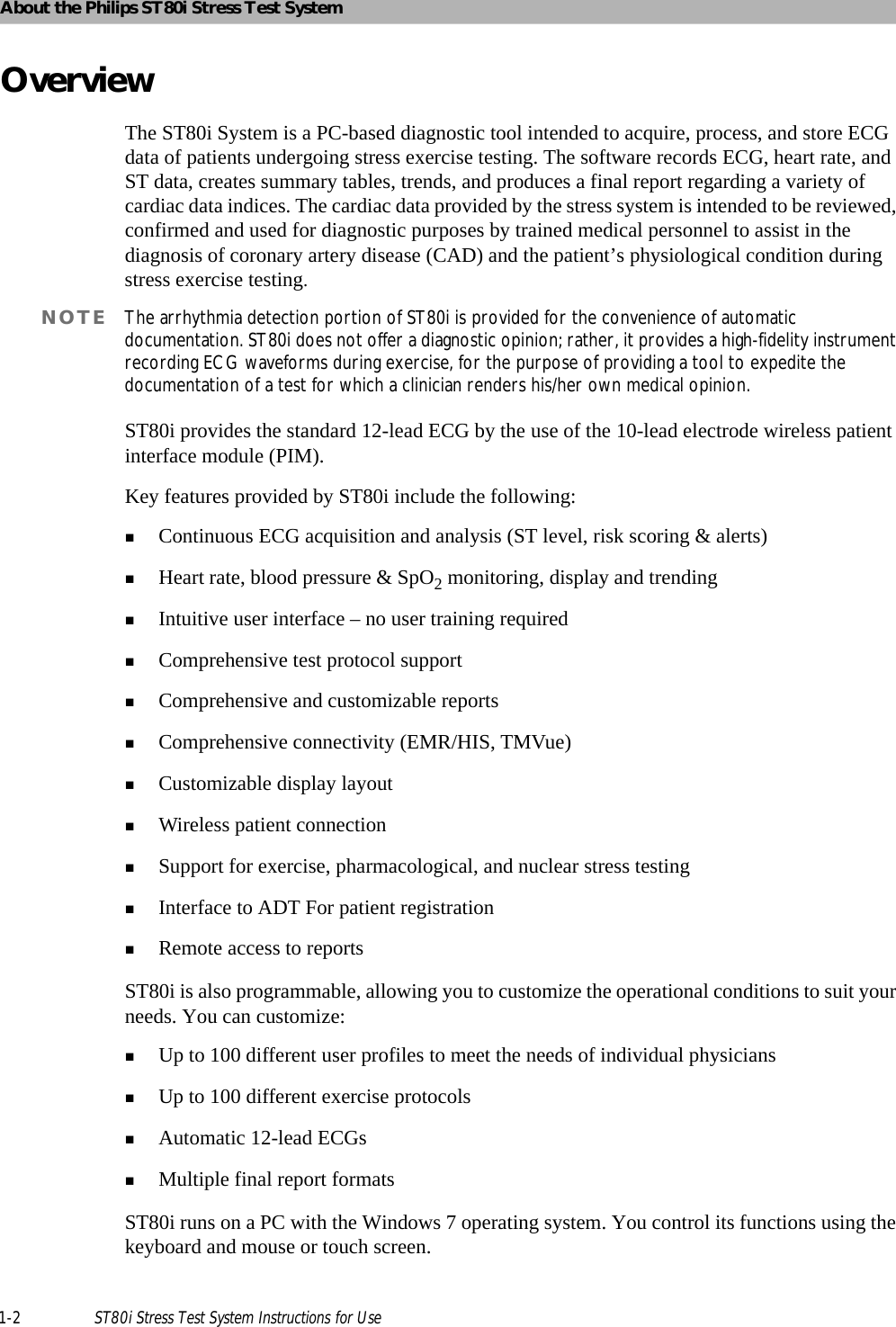
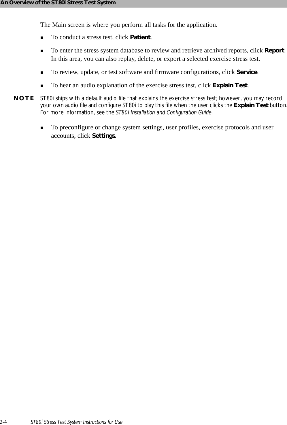
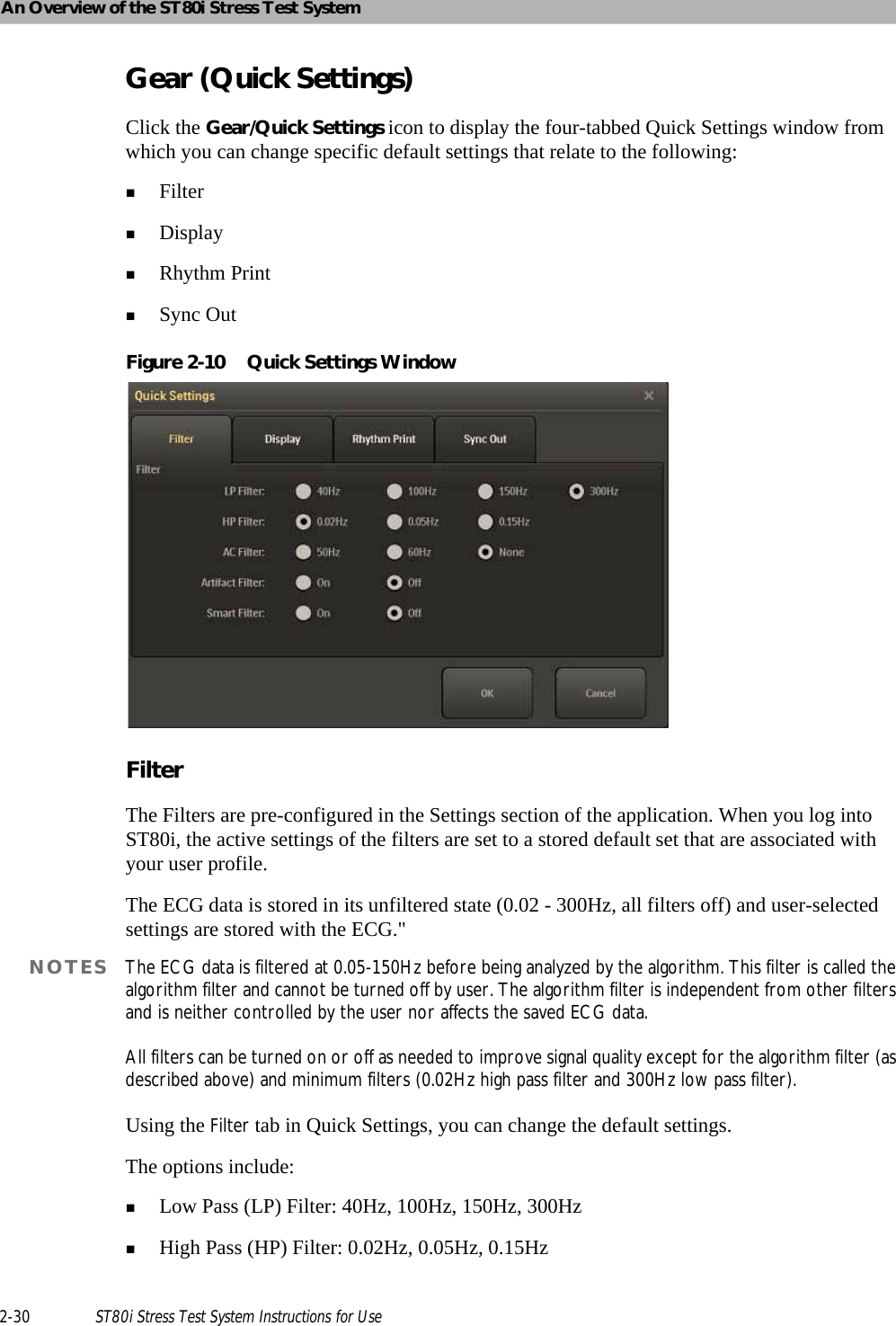
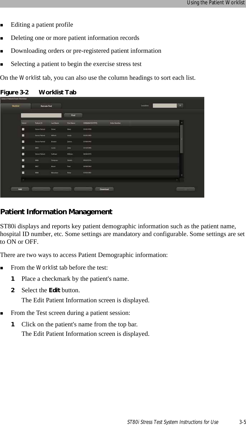
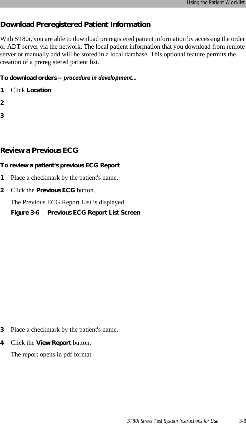
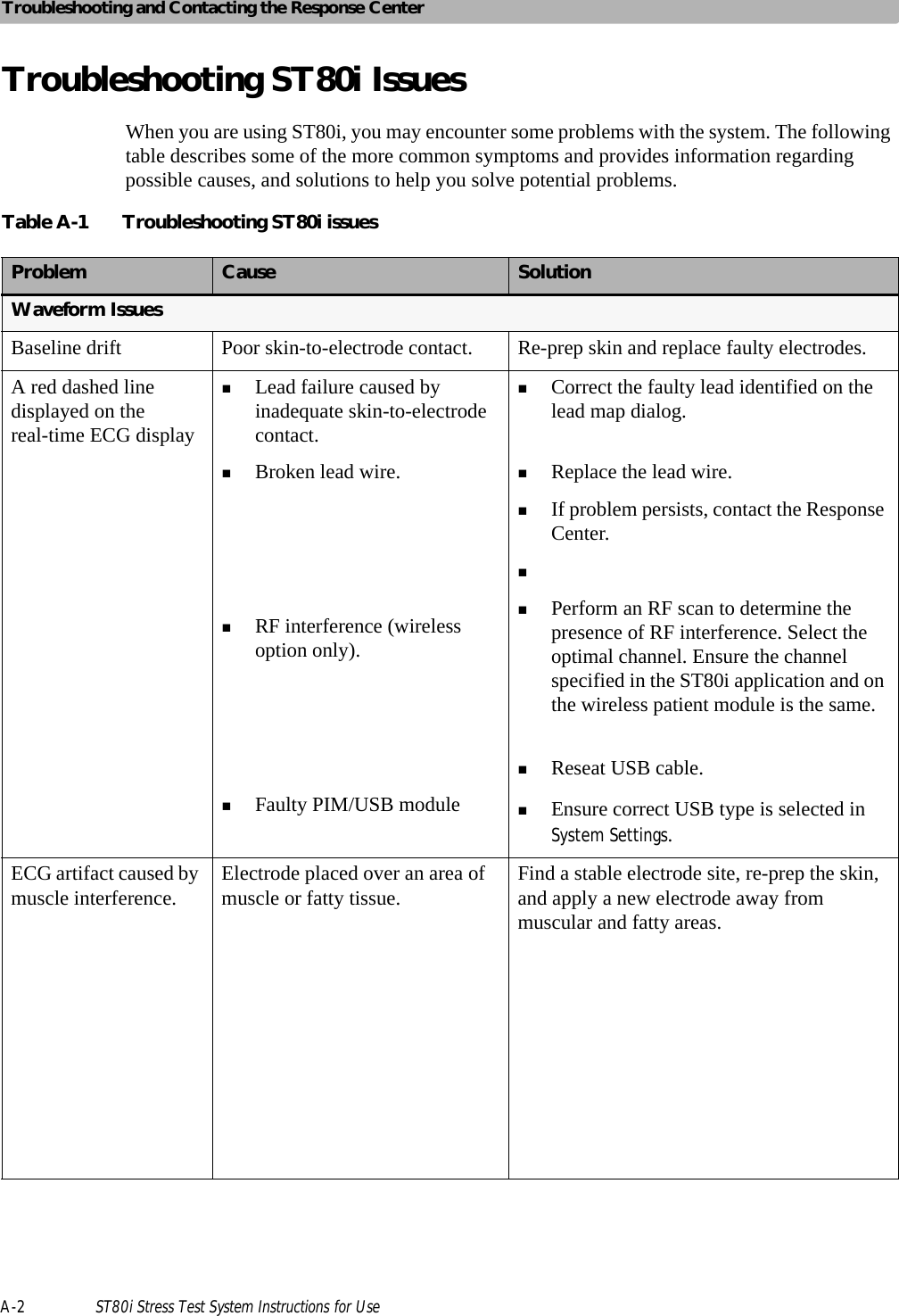
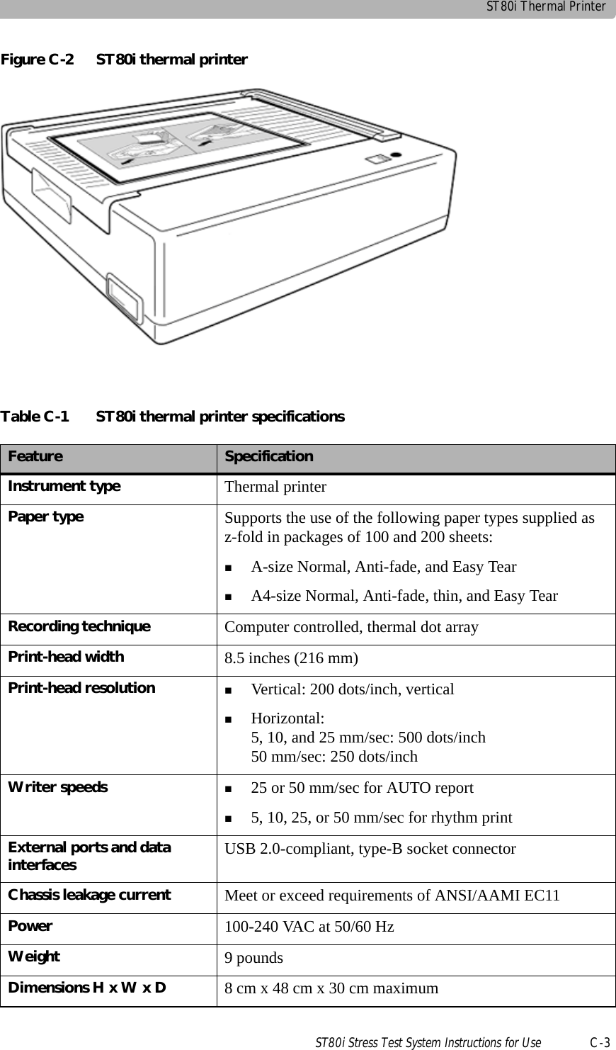
![ST80i Test ScreenST80i Stress Test System Instructions for Use 2-9Procedure BarBy default, the Procedure Bar is at the top of the screen. You can change the location of the Procedure Bar to the bottom of the screen. See the ST80i Installation and Configuration Guide to change the default setting [Settings User Profile Display].Figure 2-5 Procedure BarTable 2-3 Procedure Bar FeaturesFeature DescriptionACurrent exercise phase (Pre Exercise, Exercise, Recovery, Report)BPIM device (only in the Pre Exercise stage)CProtocol (Protocol drop-down list)DBP button - used to manually command the optional automatic blood pressure (NIBP) device to take an unscheduled blood pressure measurementEPrint ECG buttonFRhythm print buttonGAdvance (to the next stage) or Stop buttonsHExercise stage and timeIPhase buttons (Pre Exercise, Exercise, Recovery, Report) - next phase is illuminated in greenABCDEFGHI](https://usermanual.wiki/Philips-Medical-Systems-North-America/ST80IAIM/User-Guide-1723687-Page-47.png)
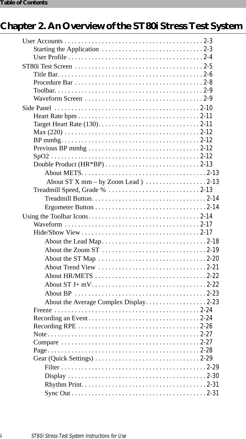
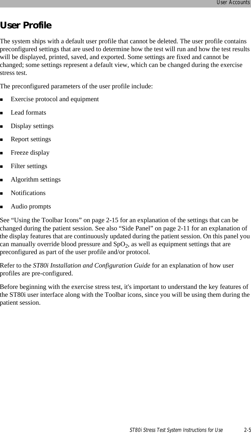
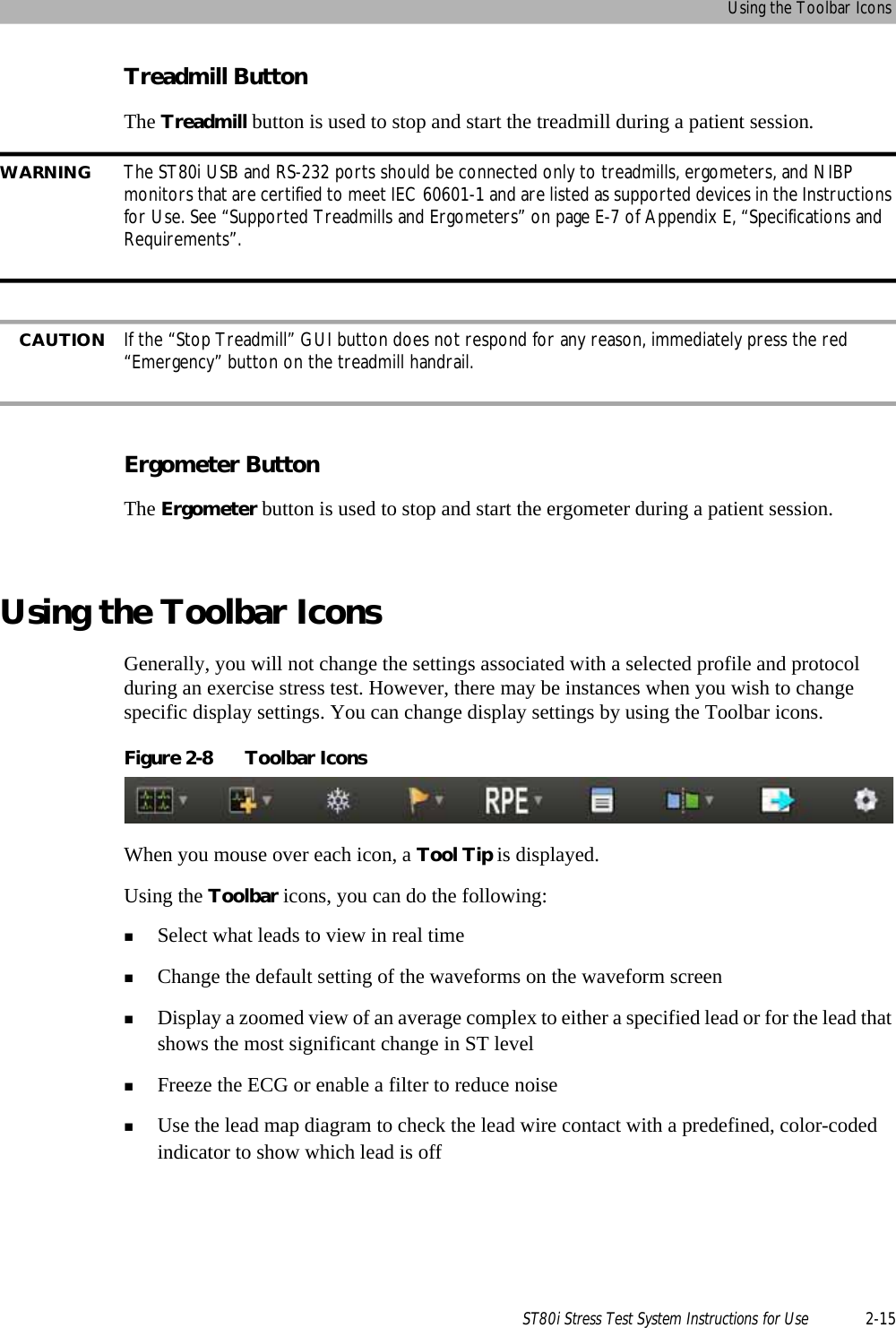
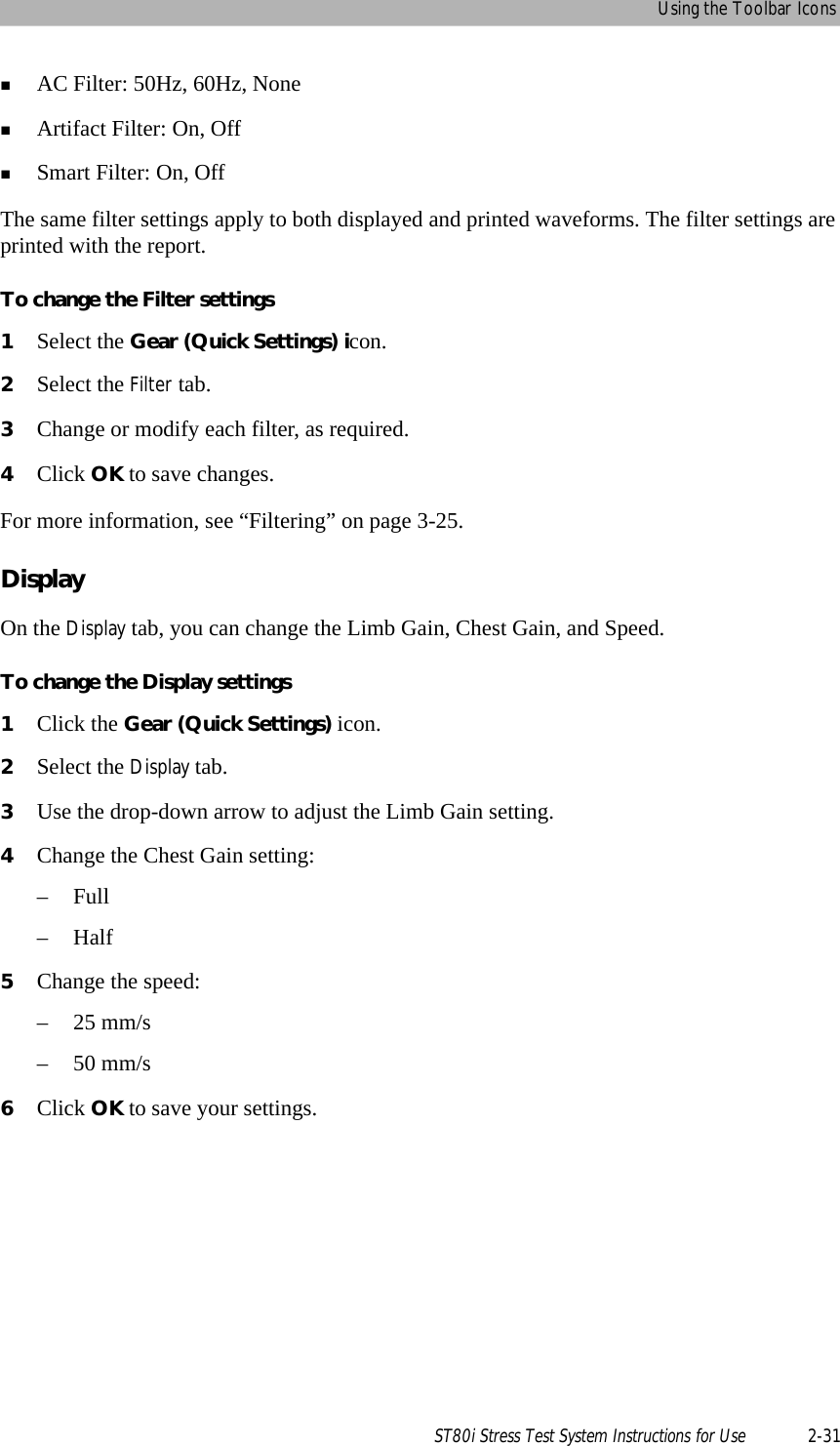
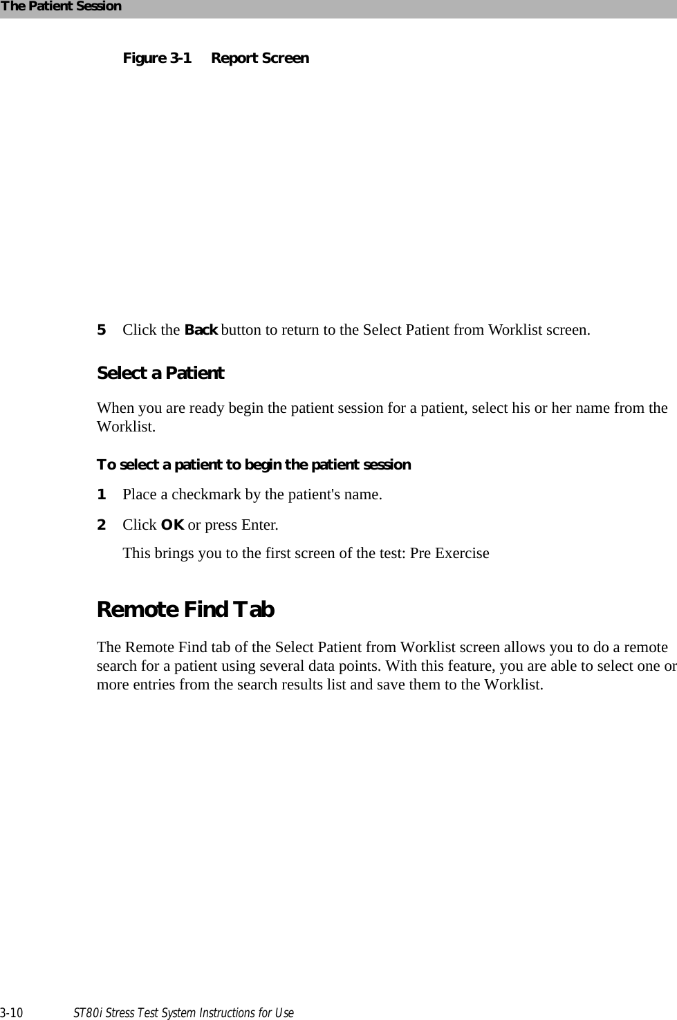
![An Overview of the ST80i Stress Test System2-10 ST80i Stress Test System Instructions for UseToolbarThe Toolbar contains the Toolbar icons that are used during the patient session. The icons provide quick access to frequently used commands.During the patient session, the waveform screen is displayed. You can use the Toolbar icons during the patient session to view or hide specific exercise stress test data - which appear as an overlay on the waveform screen.Some of the icons allow you to change specific default settings as you proceed through each phase of the patient session, while others give you a magnified view of various data in relation to the ECG.When you mouse over each icon, a Tool Tip is displayed.See “Using the Toolbar Icons” on page 2-15 for a complete description of the icons and their functionality.The default setting for the Toolbar is at the top of the screen. You can change the location of the Toolbar to the bottom of the screen. See the ST80i Installation and Configuration Guide to change the default setting [Settings User Profile Display].Waveform Screen Real-time ECG waveforms appear on the Waveform screen. The default setting is 12-Lead. With the customizable options of ST80i, you can use the Toolbar icons do the following:Change the default lead you want to view (12, 6x2, 6, 3)Display the magnified beatDisplay and/or print the average complexesShow or remove magnified beat, trends, anatomical representations and average complexes from the ECG print strip On the bottom of the screen, the current settings appear for the following:Limb Lead amplitudeChest Lead amplitudeSpeed of trace displayFilter – low and high passFigure 2-6 Limb Lead, Chest Lead, Speed, and Filter SettingsWhen you change these default settings using the Toolbar icons, they appear in this location.](https://usermanual.wiki/Philips-Medical-Systems-North-America/ST80IAIM/User-Guide-1723687-Page-48.png)
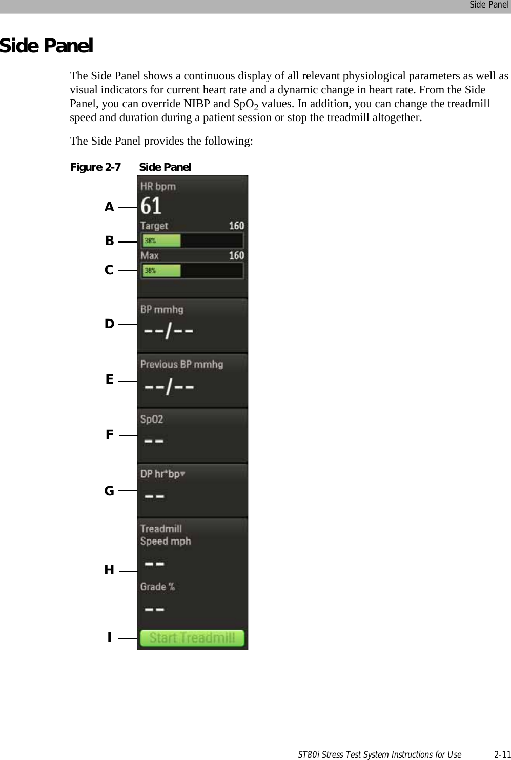
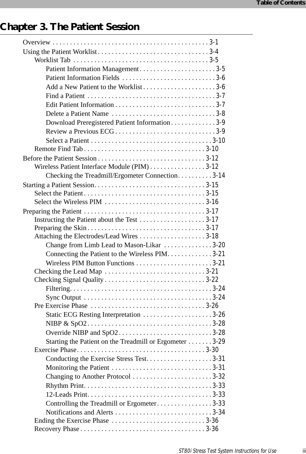
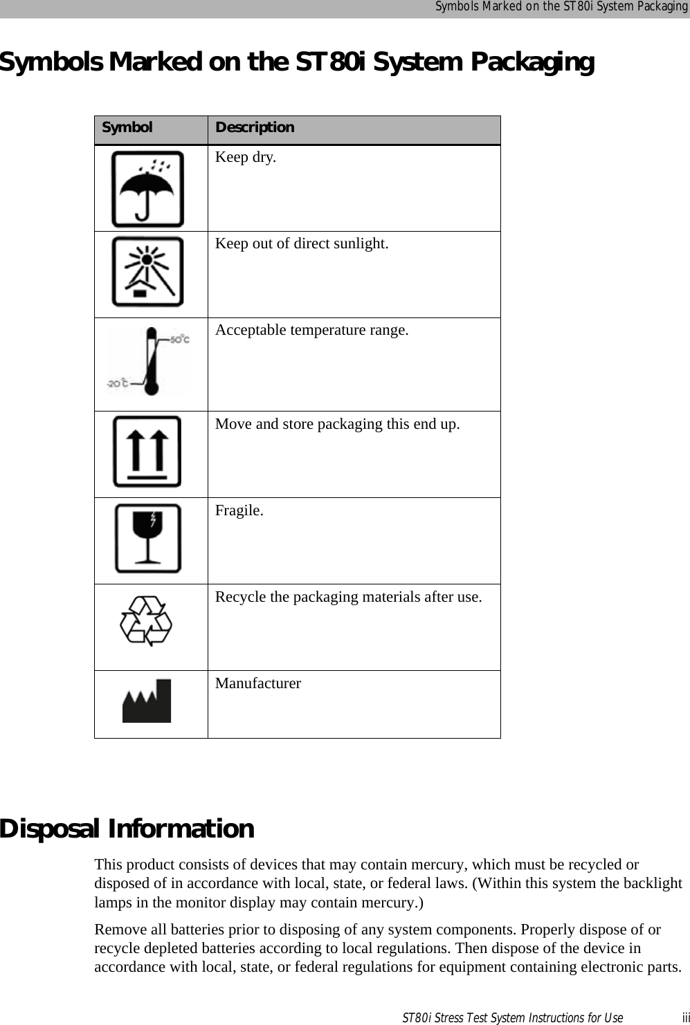
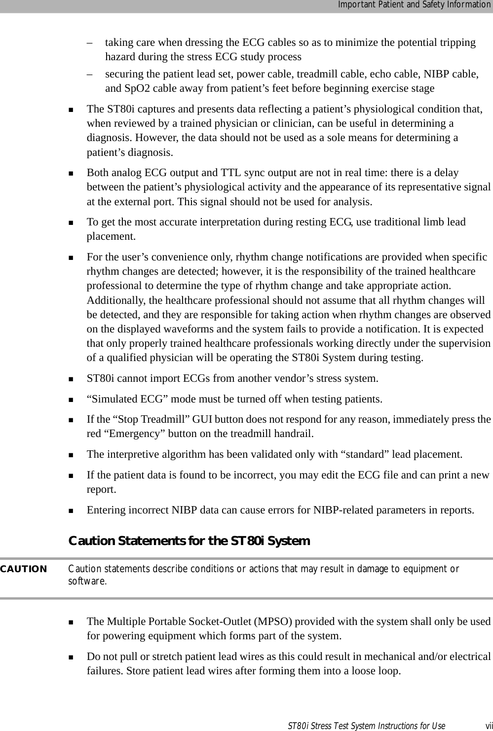
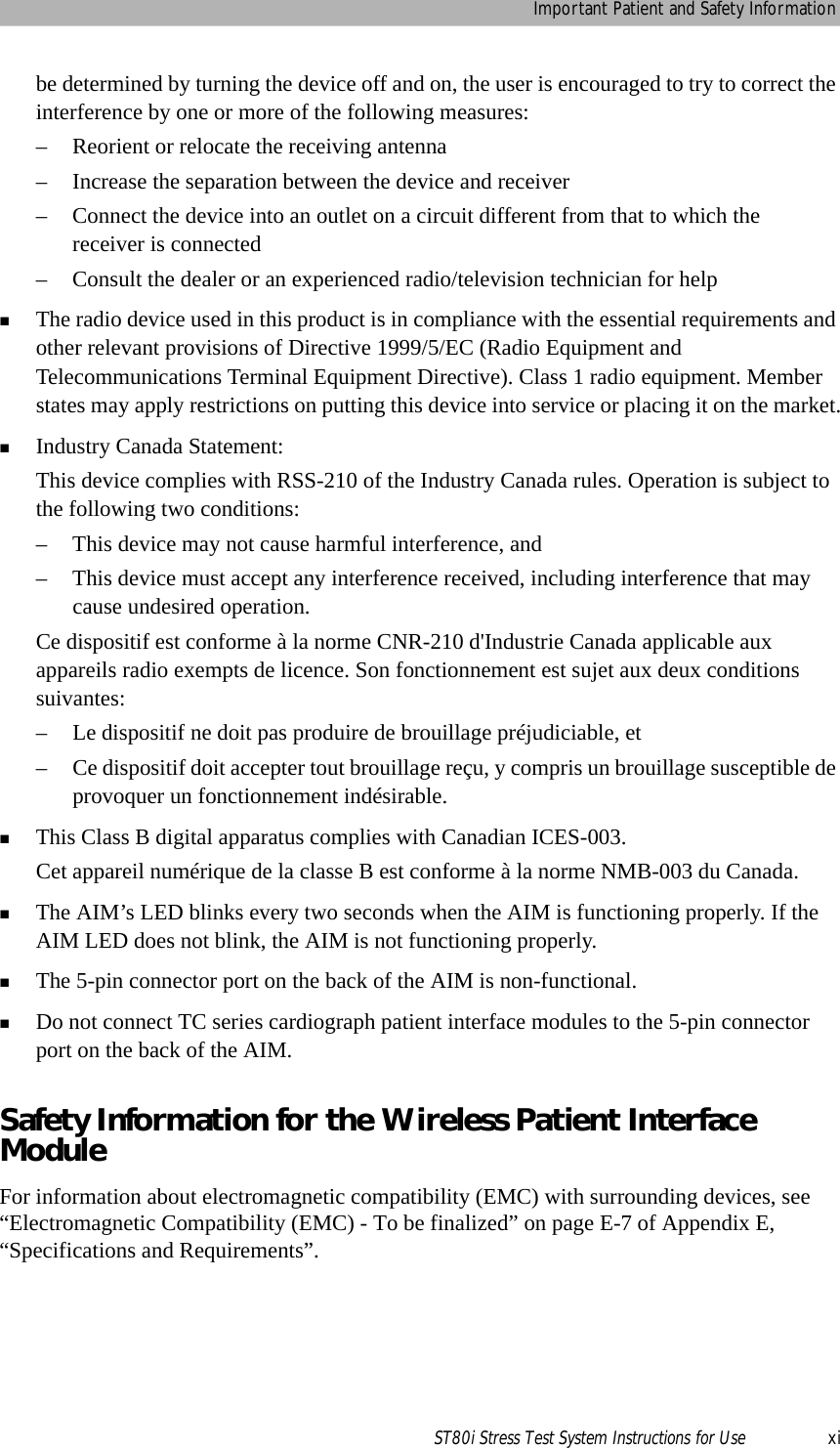
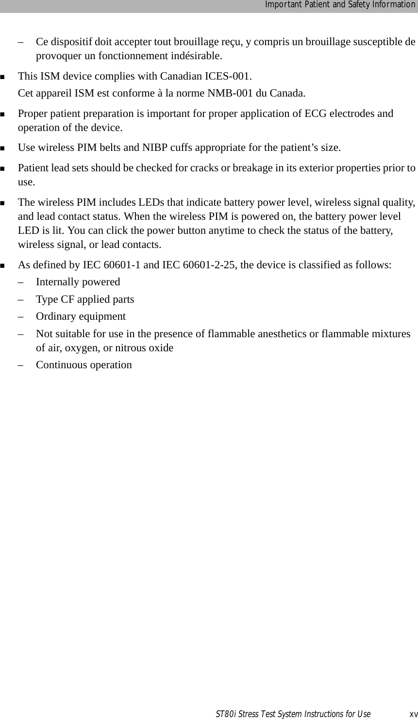
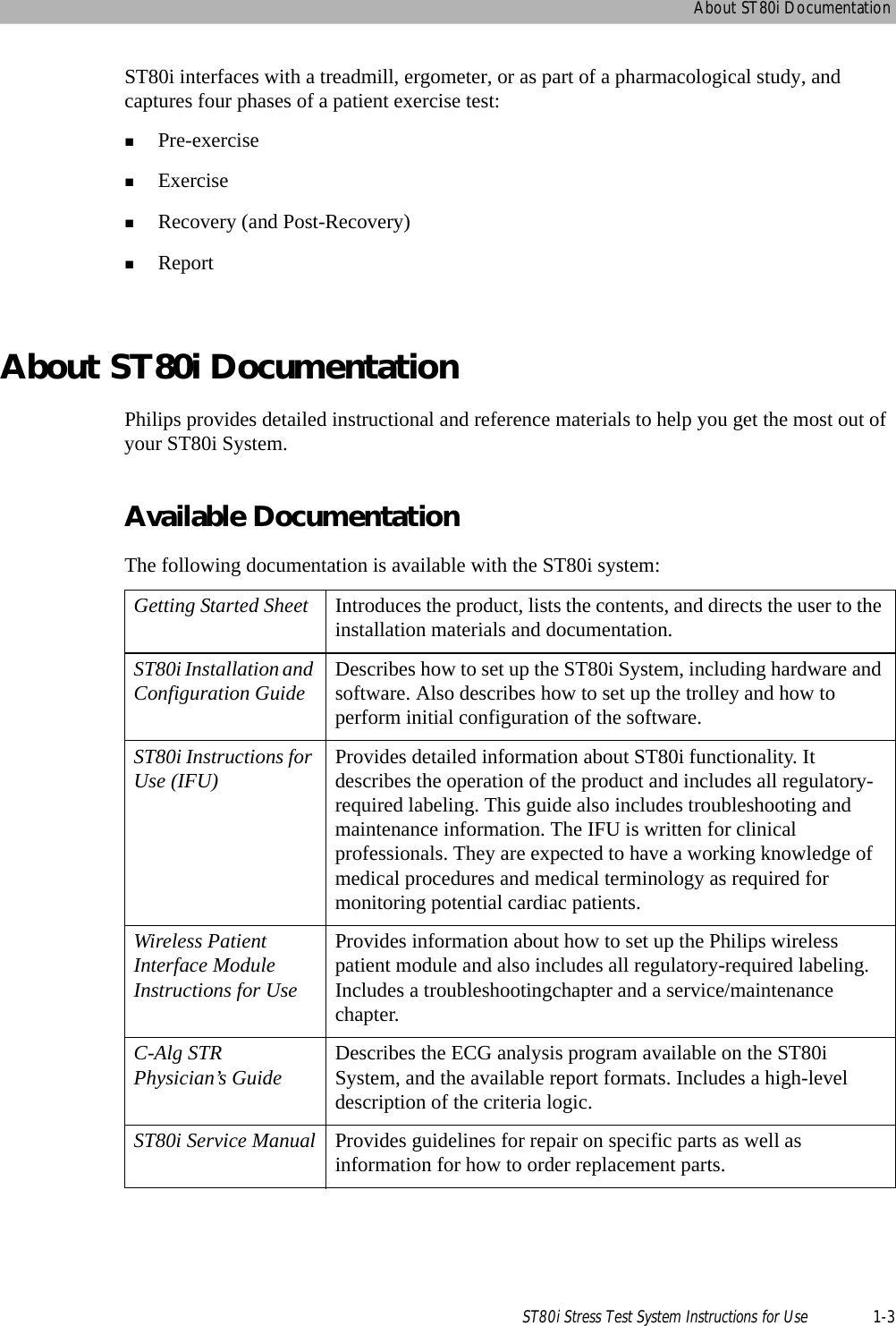
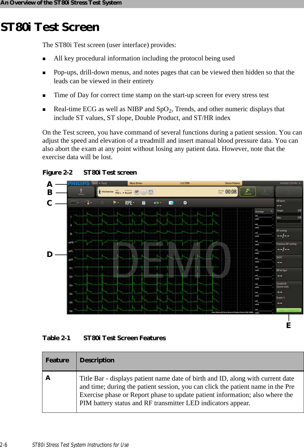
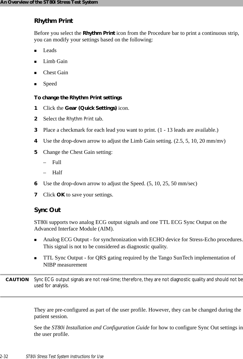
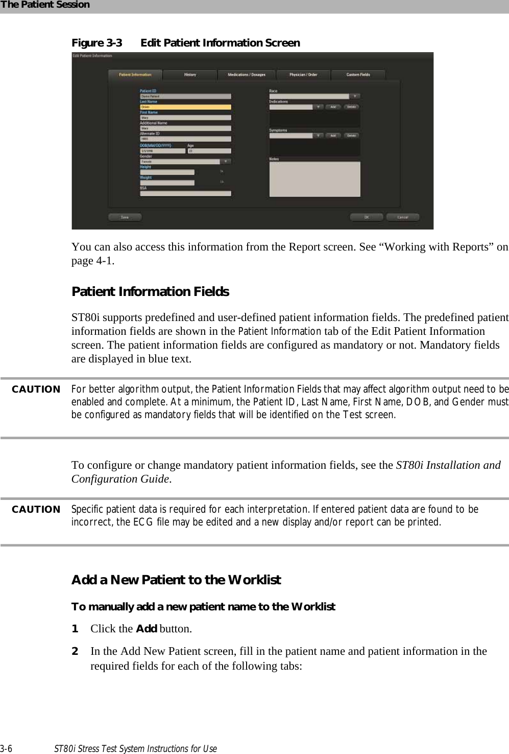
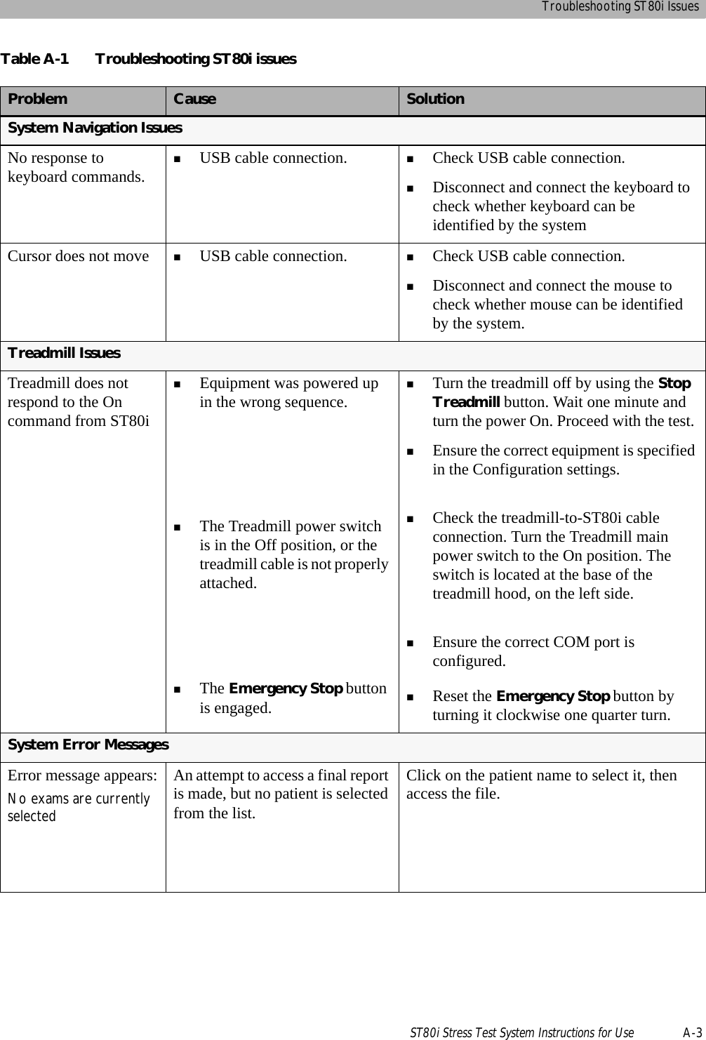
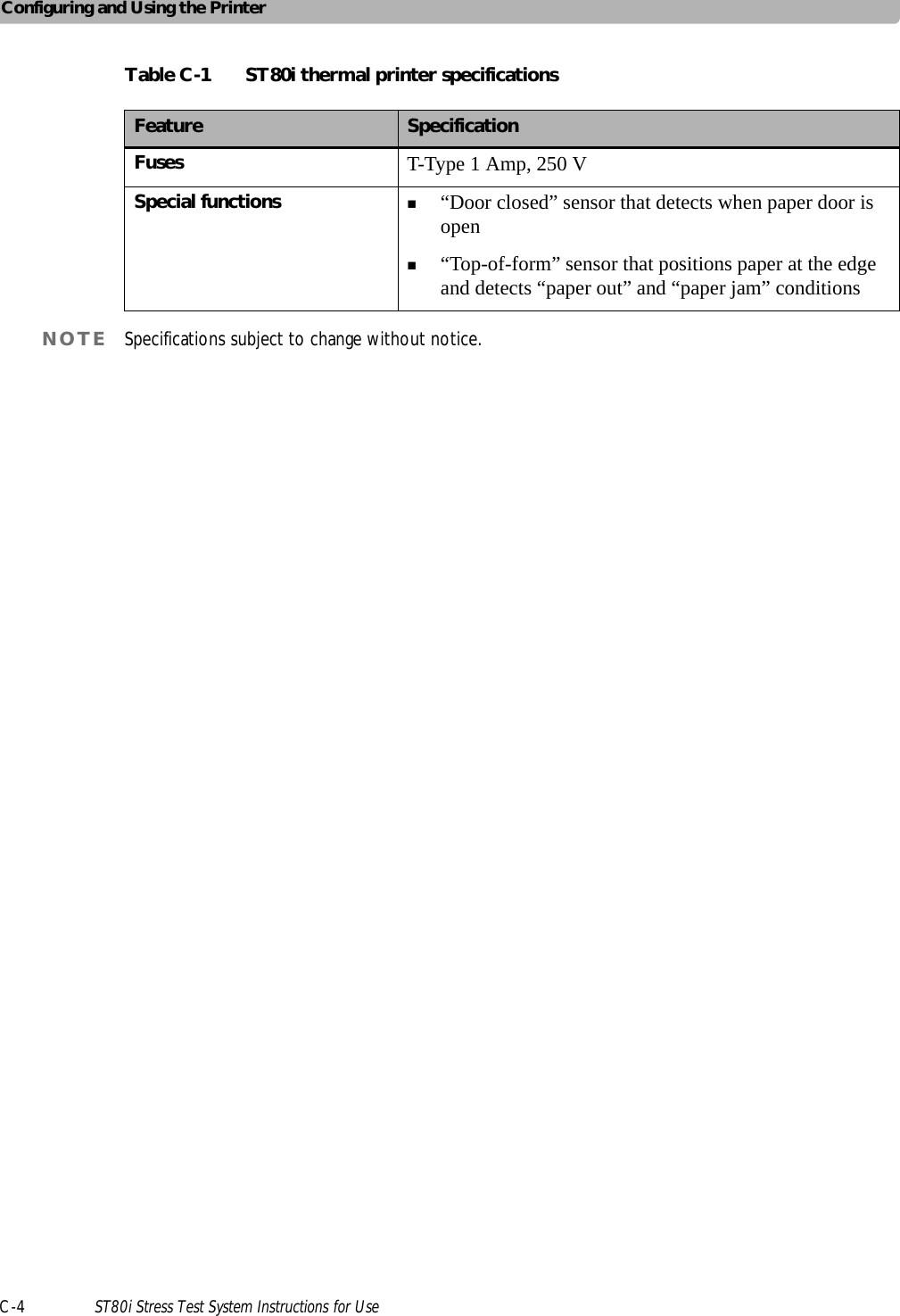
![An Overview of the ST80i Stress Test System2-12 ST80i Stress Test System Instructions for UseTable 2-4 Side Panel FeaturesHeart Rate bpmThis field shows the current heart rate of the patient.Target Heart Rate (130)There are visual and audible indicators when the target heart rate is achieved.This field shows the % of Target Heart Rate achieved.Target Heart Rate is X% of maximum heart rate – as established in User ProfileTarget Heart Rate % is pre-set (typically 85%)See the information regarding Target Heart Rate in the ST80i Installation and Configuration Guide.Feature DescriptionAHeart rate beats per minuteBTarget heart rate – visual and audible indicators when target heart rage is achievedCMaximum heart rateDBP mmhg – current blood pressure; used also to manually insert current BP measurementEPrevious BP mmhg – when BP is taken as pre-configured by stage, previous BP is shown; previous BP is also shown when you manually insert current BP measurementFSpO2 numeric data with appropriate stage; you can manually insert SpO2 dataGDP hr*bp (Double-Product – default); drop-down includes:METS – establishes metabolic equivalent [Algorithm calculation of HR, speed of Treadmill, etc.]ST mm – ST IndexHTreadmill speed (mph), grade %, or ergometer wattsITreadmill or Ergometer button (Start/Stop). The button displays “Unavailable” when the treadmill or ergometer is unavailable.](https://usermanual.wiki/Philips-Medical-Systems-North-America/ST80IAIM/User-Guide-1723687-Page-50.png)
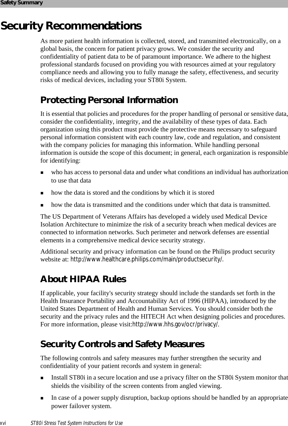
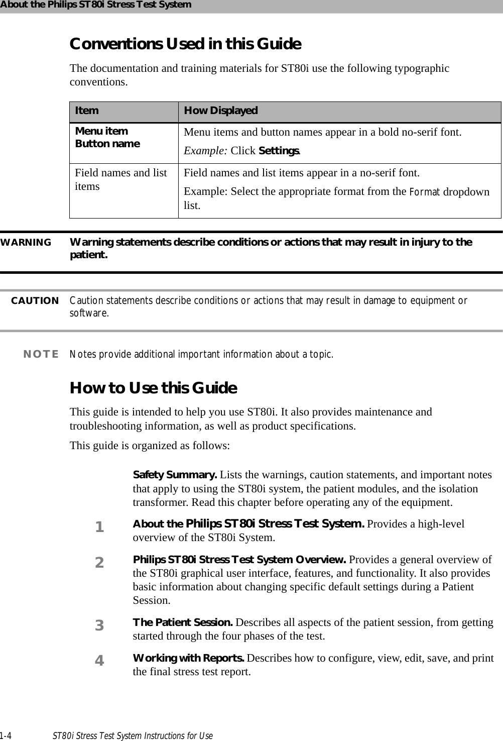
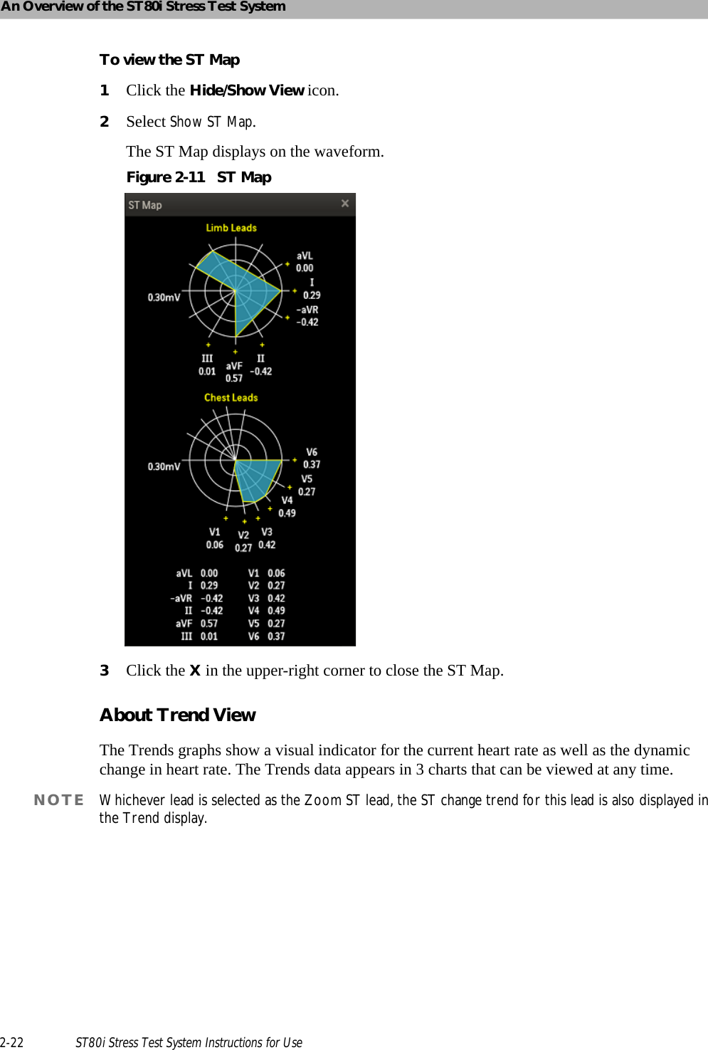
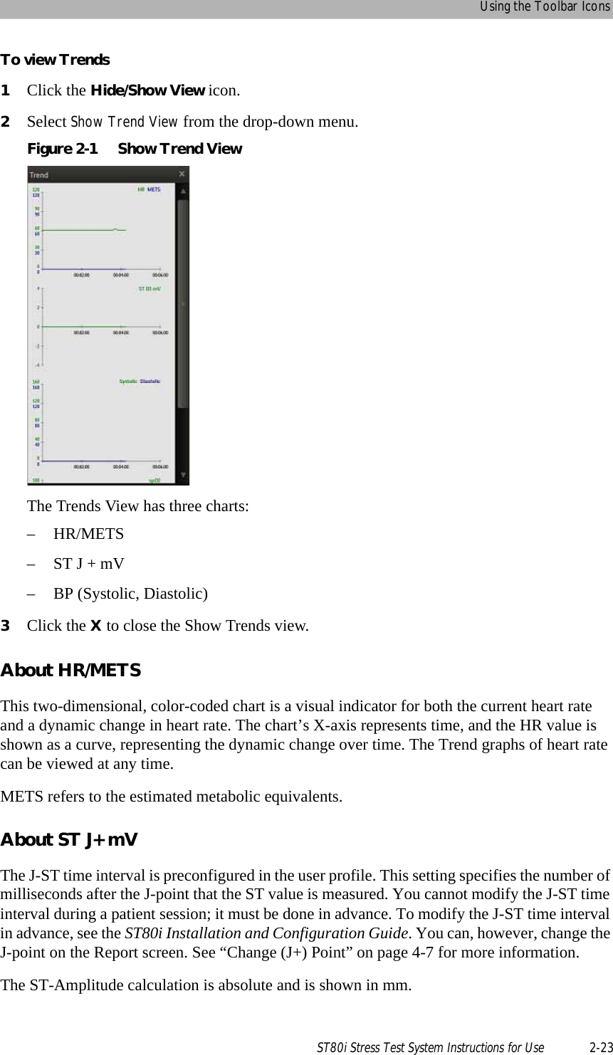
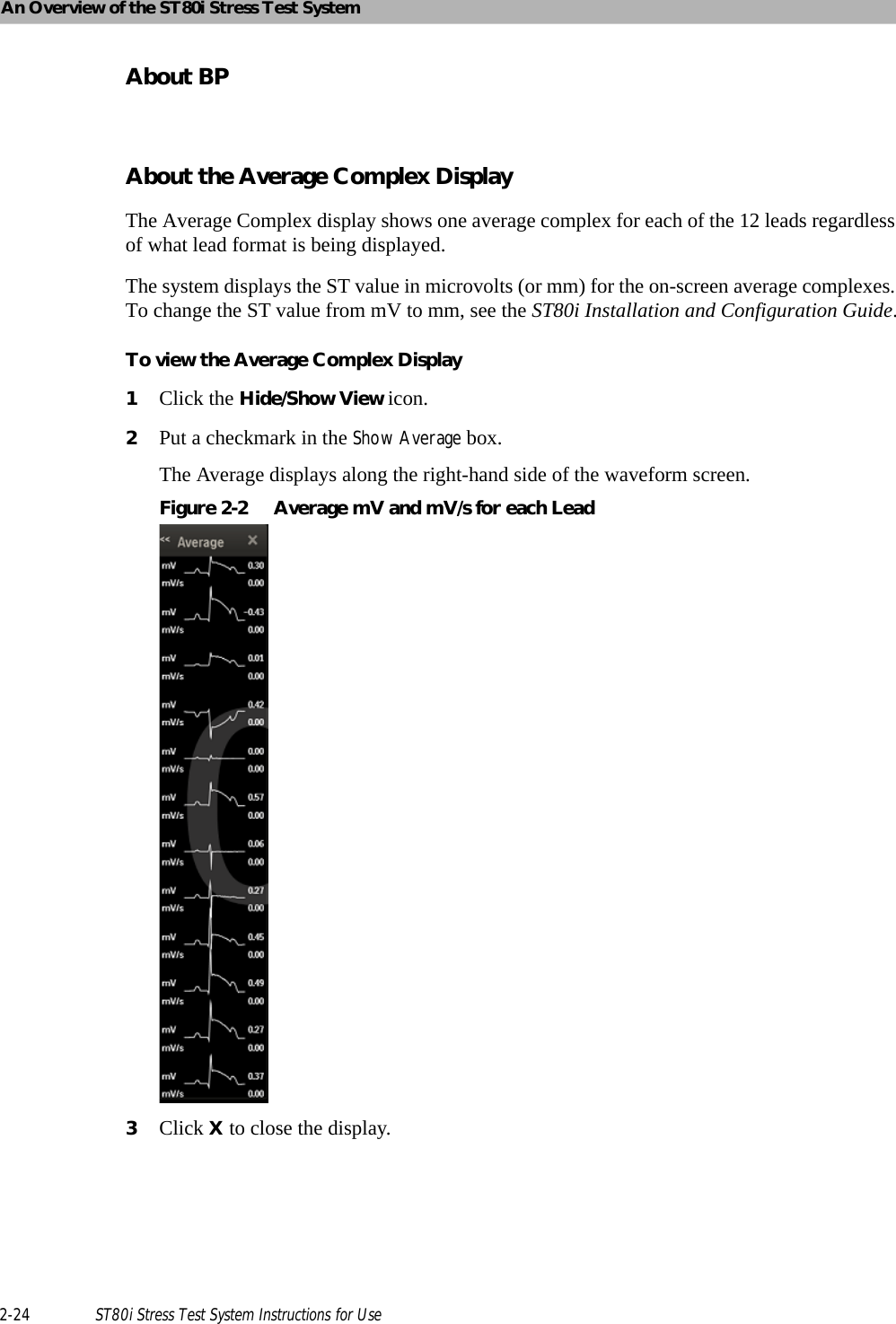
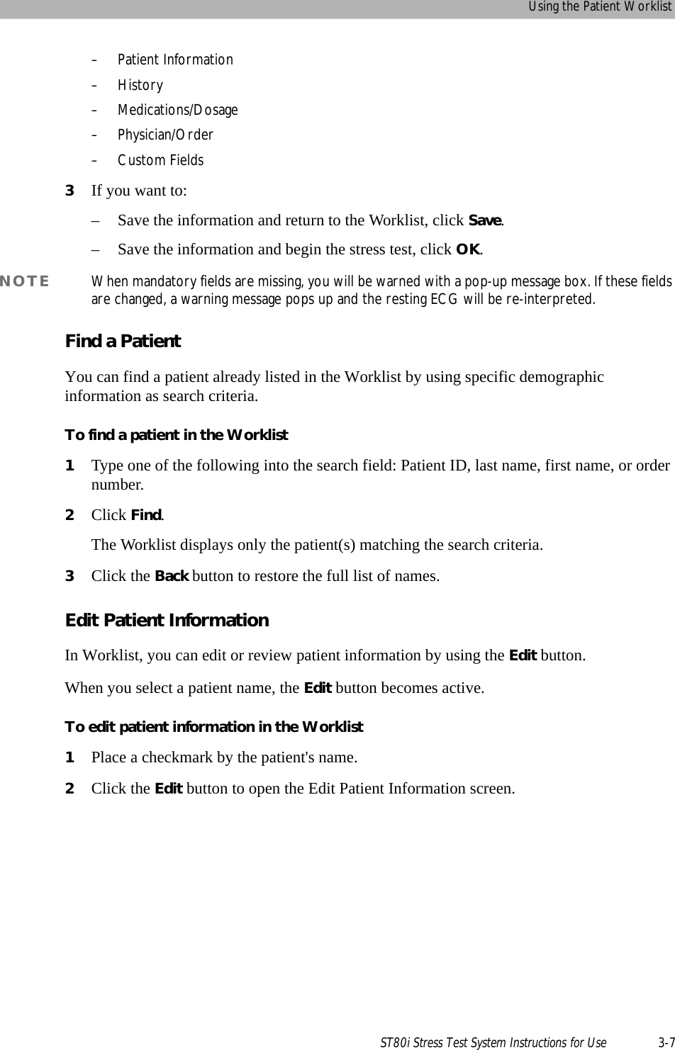
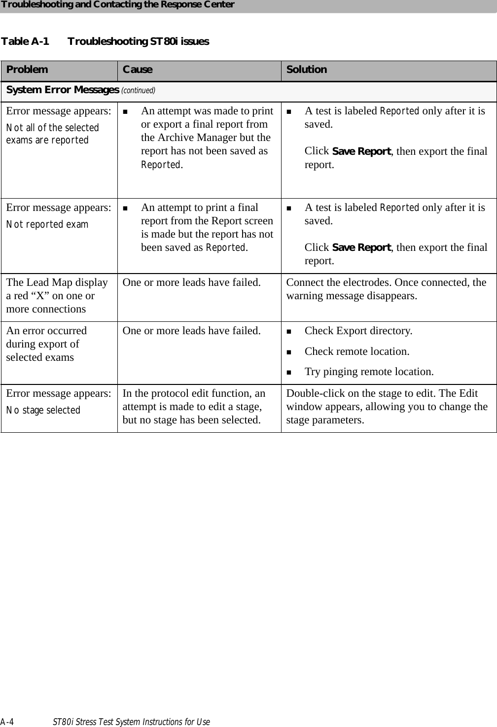
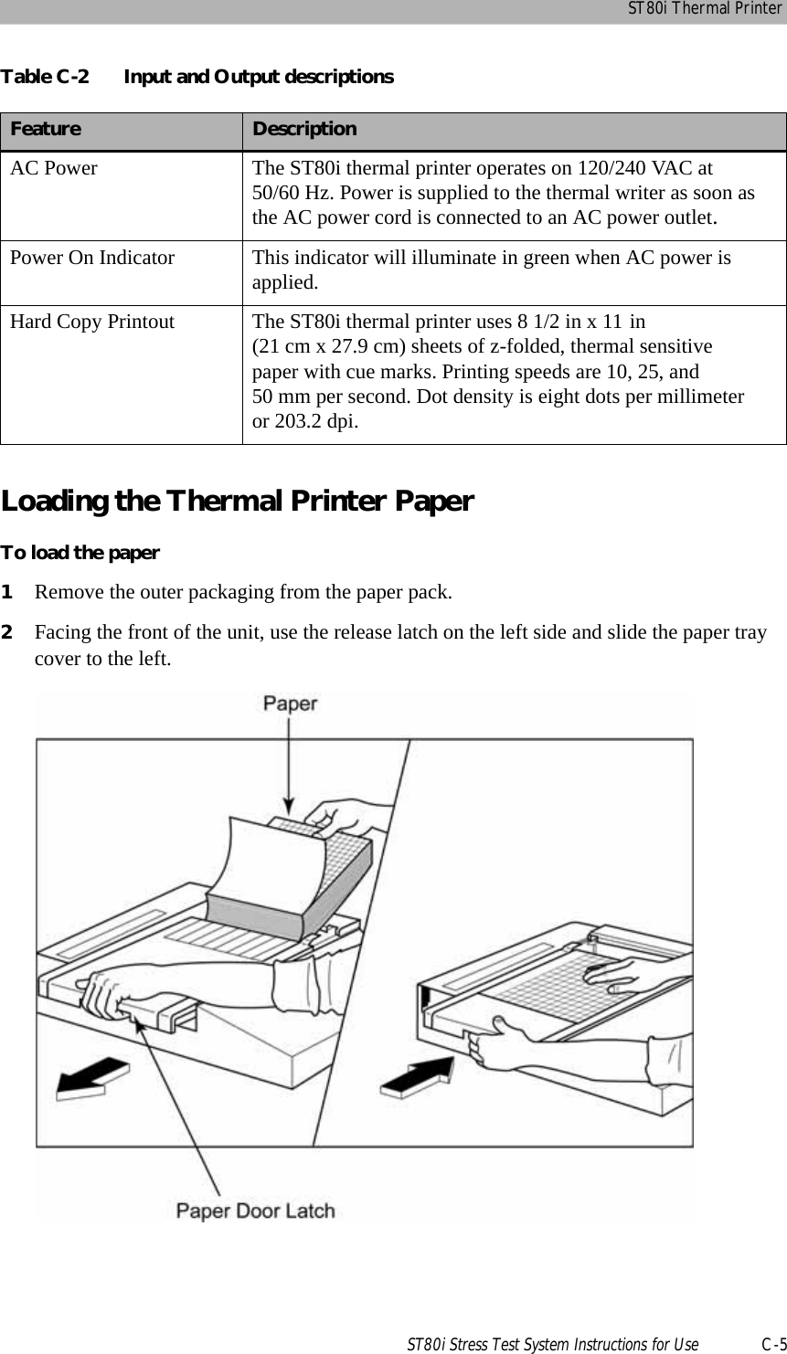
![An Overview of the ST80i Stress Test System2-16 ST80i Stress Test System Instructions for UseCompare the current averages with reference ECG (resting, supine, hyperventilation averages) and worst case for all 12 leads. ST80i is able to select a new ECG complex or 10s strip as the new reference. This can be done on the screen and is available at any point during the test. Hide or show the magnified beat, trends, anatomical representations (ST Map) and average complexes that appear over the real-time waveform displayView a two-dimensional, color-coded anatomical representation of ischemic area/segments (ST Map); 2D real-time updates anatomical representation (ST Map) every 10 seconds Create events during the test with associated notesView trend graphs for Heart Rate, METS, BP, SpO2, and ST values at any timeView magnified ST and morphological changes (including ST morphology changes, T wave morphology changes, QRS morphology changes) in the various leads.The following table provides an overview of each icon.Table 2-5 Toolbar IconsIcon DescriptionWaveform The default is 12 leads; you can select from the following:12 Leads6x2 Leads6 Leads3 LeadsHide/Show View Select from the following: Show Lead MapShow Zoom LeadShow ST MapShow Trend View [HR/METS; BP; ST Level]Show AverageNote that these settings are “sticky” – once selected they will remain until deselected.Freeze Freezes the ECG in a moment in time so that you can print the event](https://usermanual.wiki/Philips-Medical-Systems-North-America/ST80IAIM/User-Guide-1723687-Page-54.png)
![Using the Toolbar IconsST80i Stress Test System Instructions for Use 2-17Event Select the Event from the drop-down list and do X. The Events include:SupineStandMason-LikarHyperventilationChest PainShortness of BreathAdd New EventRPERate of Perceived Exertion; from preconfigured setting Note Insert comments about patient and/or testCompare Compare the current zoomed ECG with a previous moment in time to compare [the delta]PageForm-feed adjustment for thermal paper RELEARNTable 2-5 Toolbar IconsIcon Description](https://usermanual.wiki/Philips-Medical-Systems-North-America/ST80IAIM/User-Guide-1723687-Page-55.png)
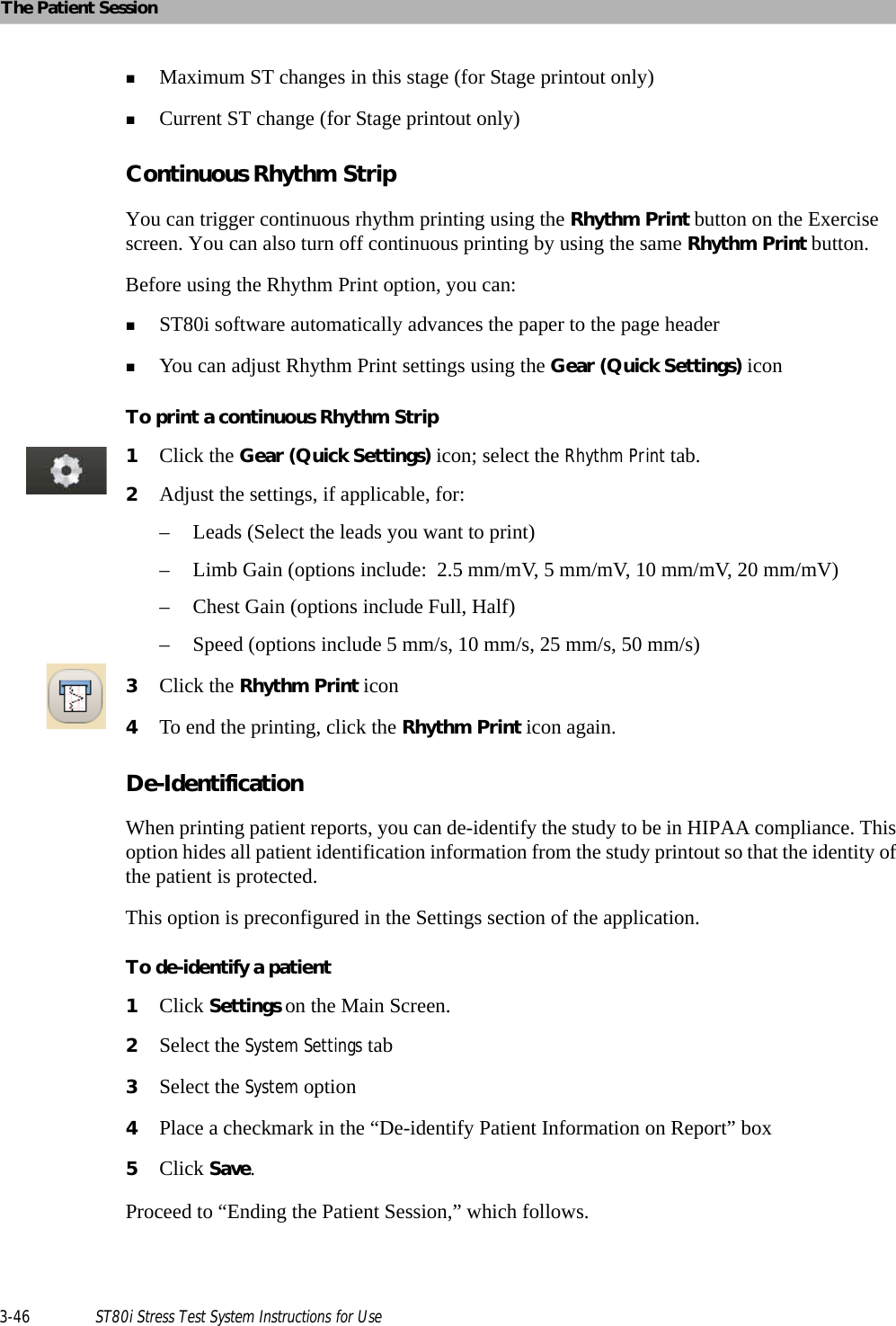
![Using the Toolbar IconsST80i Stress Test System Instructions for Use 2-33To change Sync Out settings1Select the Gear (Quick Settings) icon.2Select the Sync Out tab.3Use the drop-down menu to modify the following:– Analog Out 1 Amplify Ratio [drop-down] – [Example: Analog Out: I; Amplify Ratio: 3 mV/V]– Options: None; Leads I - V6– Analog Out 2 Amplify Ratio [drop-down] – [Example: Analog Out 2: None; Amplify Ratio: 1 mV/V– Options: None; Leads I - V6– TTL Out Polarity/Duration (ms) [drop-down] – [Example: TTL Out: None; Polarity: Positive; Duration: 50 ms]– Options: None; Leads I - V6– Polarity (Positive/Negative)– Duration: default is 100 ms.4Click OK.](https://usermanual.wiki/Philips-Medical-Systems-North-America/ST80IAIM/User-Guide-1723687-Page-71.png)
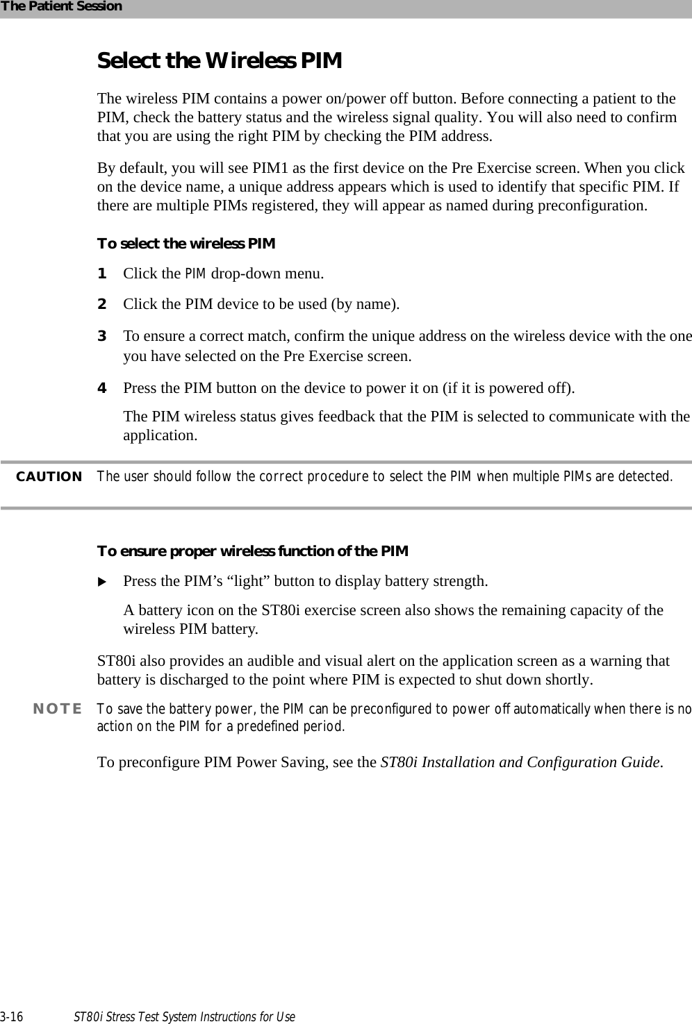
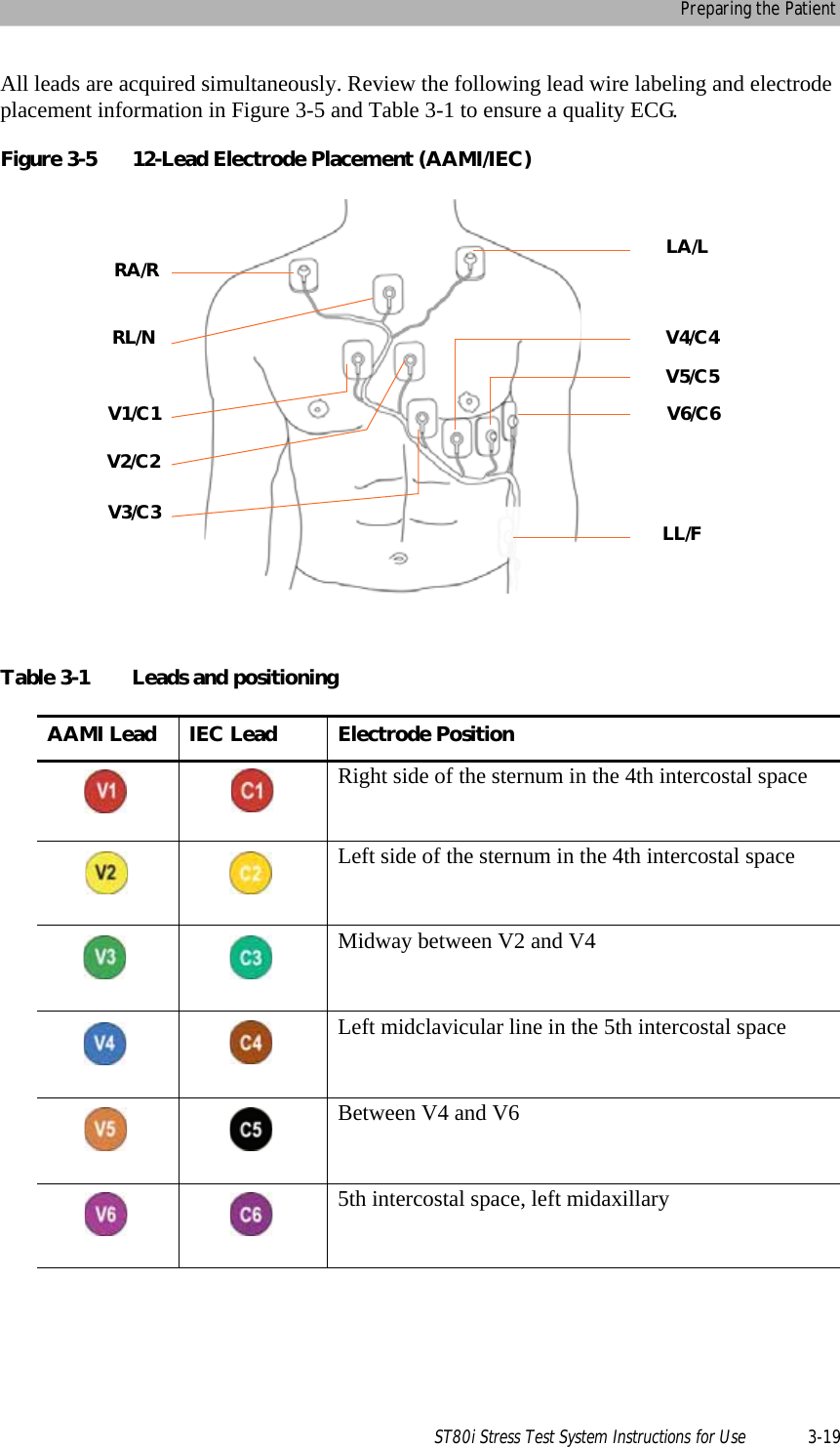
![The Patient Session3-18 ST80i Stress Test System Instructions for UsePreparing the SkinThorough skin preparation is very important. The skin is a poor conductor of electricity and frequently creates artifact that distorts the ECG signal. By performing methodical skin preparation, you greatly reduce the potential for myographic noise and baseline wander, ensuring high-quality printouts and displayed data. There is a natural resistance on the skin surface due to dry, dead epidermal cells, oils, and dirt. To prepare the skin1Shave hair from electrode sites, if necessary. Excessive hair prevents a good connection.2Wash the area thoroughly with soap and water.NOTE Do not use alcohol to clean the skin.3Dry the skin vigorously with a gauze pad to increase capillary blood flow to the tissues and to remove the dead, dry skin cells and oil.4Use an abrading pad to lightly scratch an “X” pattern into the skin, taking care to avoid excessive abrading. Attaching the Electrodes/Lead WiresPlacement of the electrodes changes depending on the stage:Supine for a resting or baseline ECGStanding for Exercise PhaseST80i supports the use of 12-lead wireless PIMs. The 12-lead wireless PIMs connect to the AIM and support 10 electrodes. Using AAMI/IEC labeling, these electrodes are: Right Leg [RL/N]Left Leg [LL/F]Right Arm [RA/R]Left Arm [LA/L]Chest leads [V1/C1, V2/C2, V3/C3, V4/C4, V5/C5, and V6/C6]](https://usermanual.wiki/Philips-Medical-Systems-North-America/ST80IAIM/User-Guide-1723687-Page-90.png)
![The Patient Session3-34 ST80i Stress Test System Instructions for UseRhythm PrintYou can print a continuous rhythm strip directly from the ST80i screen at any point during the test. The system generates a continuous report (configurable from 1 to 12 leads) of the leads specified in the configuration for the particular profile. For details, see the ST80i Installation and Configuration Guide. The continuous rhythm strip contains the patient's name and the current date and time. You can generate continuous rhythm strips during all phases of a test.Any scheduled automatic 12-lead or manually generated events that occur during continuous rhythm printing are saved for later review or printing and are included in the final report. To change the settings for Rhythm Printing before printing the Rhythm Strip1Use the Page icon to set the top of the page2Use the Gear/Quick Settings icon [Gear/Quick Settings Rhythm Print] to set the Leads, Limb Gain, Chest Gain, and Speed.To print a continuous strip1Click the Rhythm Print icon.A continuous Rhythm Strip will print.2Click the Rhythm Print icon again to stop the strip from printing.12-Leads PrintThe timed printing of the 12-Lead ECG is based on the Exercise Protocol settings that are preconfigured on the Config screen’s Exercise Protocol tab. For details, see the ST80i Installation and Configuration Guide.In addition to the timed printing of an ECG, you can also generate 12-lead ECGs during all phases of the test. Select this icon if you want to print a 12-lead ECG in real time.NOTE 12-Lead ECG also prints when an Event or RPE is recorded. The ECG also includes pacemaker detection as well as arrhythmia notification, if enabled.To print a real-time 12-Lead ECGClick the 12-Leads Print icon.A 12-Lead ECG will print.](https://usermanual.wiki/Philips-Medical-Systems-North-America/ST80IAIM/User-Guide-1723687-Page-106.png)
![The Patient Session3-36 ST80i Stress Test System Instructions for UseTo stop the treadmill during the Exercise phaseClick the Stop Treadmill button.The Treadmill stops.Consult “Maintaining the ST80i System” on page 5-1 with regard to the inspection of cables and attachments between the PC and the Treadmill.Notifications and AlertsST80i provides visual indications or alerts in case of dramatic morphology or rhythm changes. All notifications are preconfigured in the user profile. They include the fields to be displayed or printed as well as specific audio alerts.As part of the user profile, you can select to display and/or print the following Arrhythmia fields:Asystole [SRS 3.2.14.3.14]Absolute Pause1 missing beat2 missing beatsVentricular FibrillationVTSVTPremature Ventricular Contractions (PVC)Extreme HRSudden drop in BPVrun(>=3PVs)Vcouplet(2 PVCs)Ventricular BigeminyVentricular Escape BeatsAfib The preconfigured audio alerts consist of the following:NIBPSpO2DoseNotifications](https://usermanual.wiki/Philips-Medical-Systems-North-America/ST80IAIM/User-Guide-1723687-Page-108.png)
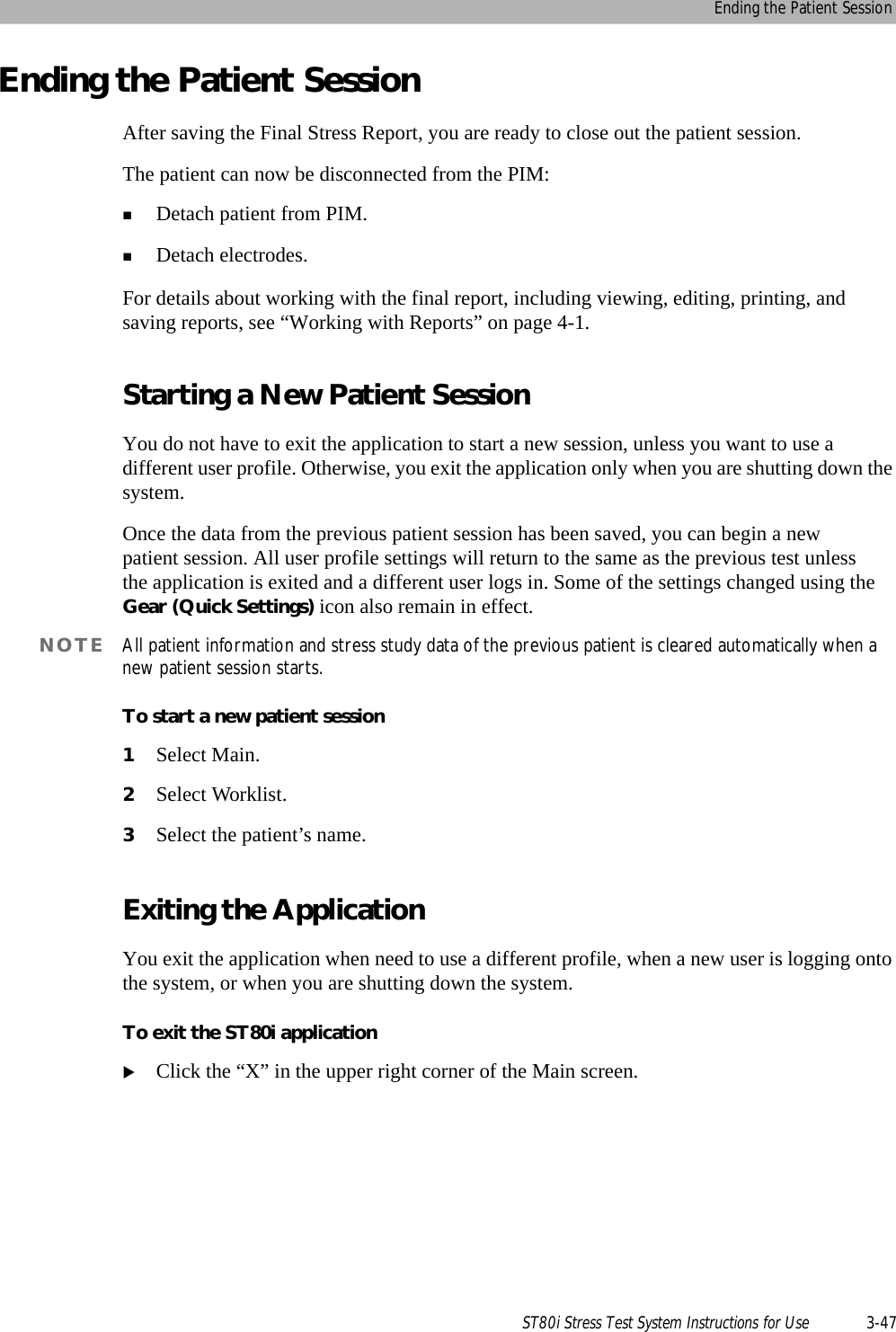
![The Patient Session3-42 ST80i Stress Test System Instructions for UsePrinting During the Stress TestAt any time during the stress test, you can trigger real-time ECG (a real-time ECG is defined as 10 seconds of ECG data) and continuous Rhythm printing using the icons displayed on the Exercise screen. The time latency should be less than 7 seconds. You can also capture and store events for later review and reporting. The events can be saved with notes and can be printed with the context ECG data.Arrhythmia events can trigger automatic printing with the context ECG, if configured. In addition, you can also turn off the continuous printing both on the configuration and during the test.Printer ConfigurationDuring the patient session, you have two print options: ECG PrintRhythm PrintSome print settings are preconfigured in advance while some can be changed during an exercise stress test. The settings include:Printer selectionTiming of Print– ECG Print - by stage– ECG manual - using the ECG Print button– Rhythm Print manual - using the Rhythm Print buttonPrint layoutOn the Config screen [System Settings System], you can preconfigure the printer for each type of report:Select ECG Report Printer:–Off– PDF Complete– Microsoft XPS Document Writer– Local Thermal PrinterSelect Event Report Printer:–Off– PDF Complete– Microsoft XPS Document Writer](https://usermanual.wiki/Philips-Medical-Systems-North-America/ST80IAIM/User-Guide-1723687-Page-114.png)
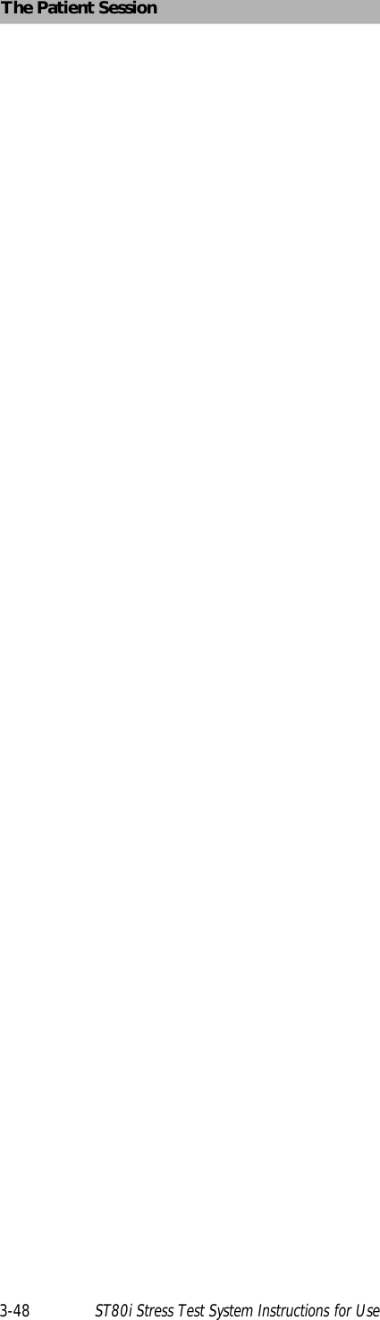
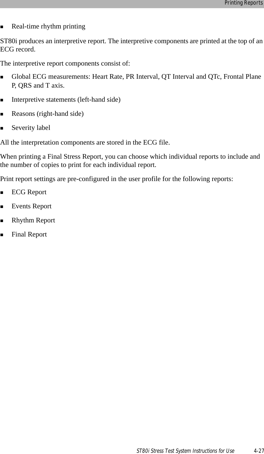
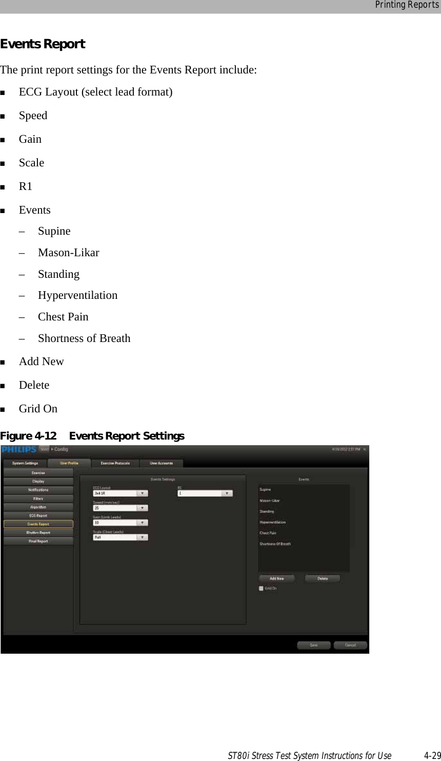
![Printing During the Stress TestST80i Stress Test System Instructions for Use 3-43– Local Thermal PrinterSelect Rhythm Report Printer:–Off– Local Thermal PrinterSelect Final Report Printer:–Off– PDF Complete– Microsoft XPS Document Writer– Local Thermal PrinterOn the Config screen [User Profile ECG Report], ECG Print is preconfigured with the following:ECG LayoutSpeed (mm/sec)Gain (Limb Leads)Scale (Chest Leads)On the Config screen, the timing of the ECG Print is configured on the Exercise Protocols tab. The print interval options include:OffBeginEndEveryLeadsYou can also print an ECG at any time by clicking the 12 Leads Print button. On the Config screen [User Profile Rhythm Report], you can configure Rhythm Print settings for the Rhythm Report. They include:ECG Layout - select LeadsRhythm Settings – Speed mm/sec - 5, 10, 25, 50– Gain (Limb Leads) - 2.5, 5, 10, 20– Scale (Chest Leads) - Full, HalfDuring the patient session, you can change the Rhythm Print settings using the Gear (Quick Settings) icon. See “Using the Toolbar Icons” on page 2-15 for an explanation.](https://usermanual.wiki/Philips-Medical-Systems-North-America/ST80IAIM/User-Guide-1723687-Page-115.png)
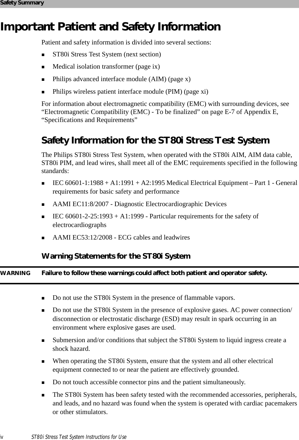
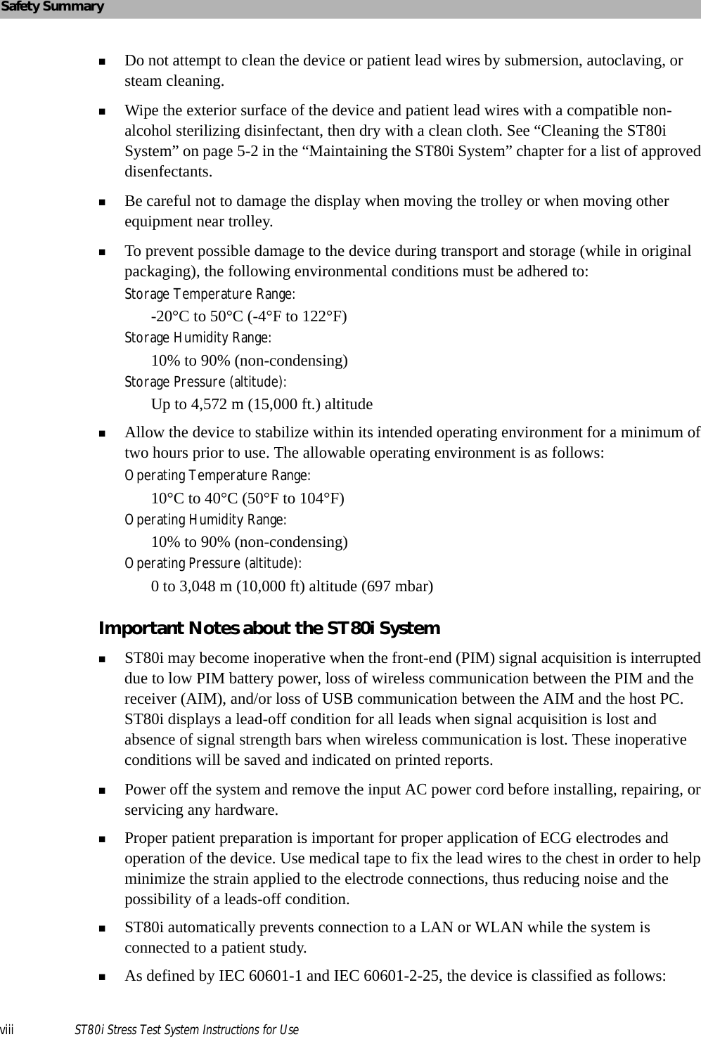
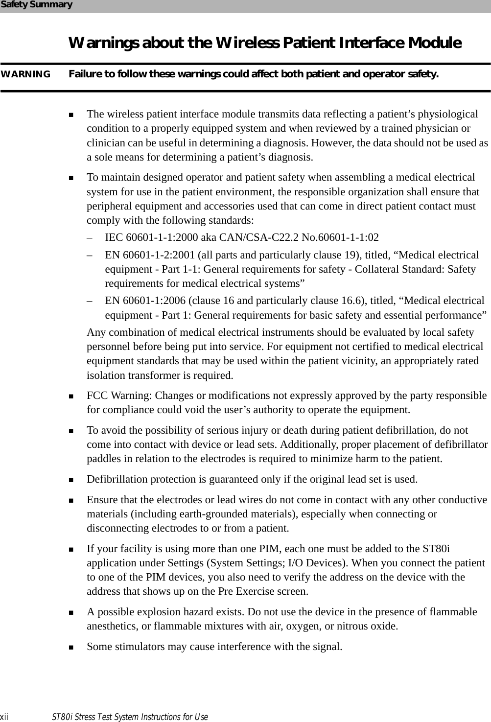
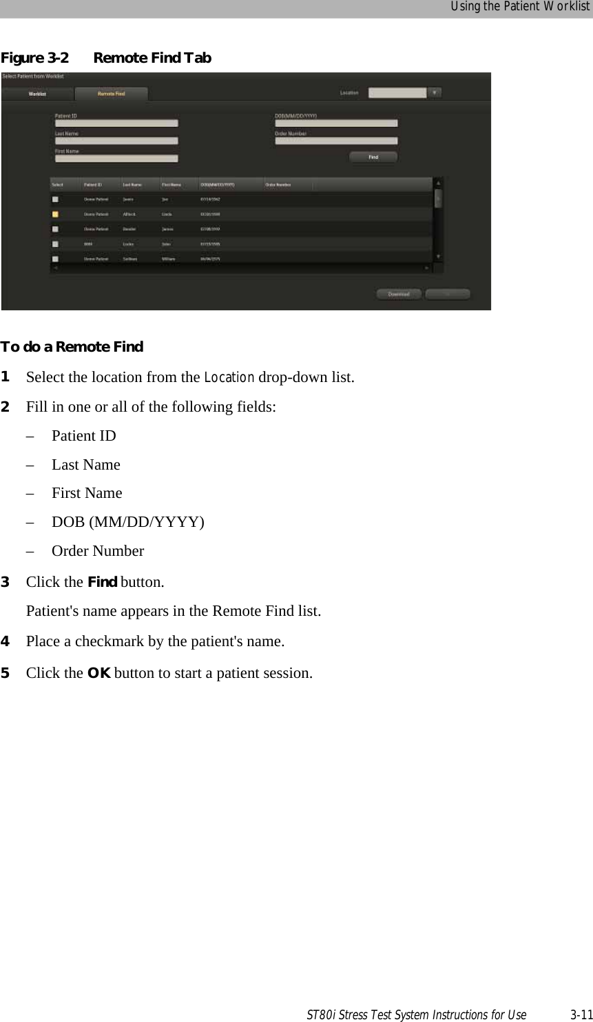
![Report ScreenST80i Stress Test System Instructions for Use 4-5Figure 4-1 ST80i Report ScreenTable 4-1 ST80i Report Screen FeaturesFeature DescriptionATitle Bar - where you enter or update patient information in the Patient Demographics window.BProcedure Bar - [Report, Status: Complete or Incomplete] and buttons: Change J+ , Save, Export, Print, Confirm, ReplayCReport Tabs Summary, Tabular, Trend Graph, Averages, Events, Resting ECG, Full DiscloseDReal-time 7.5-second ECG by selected lead (ECG for one lead is displayed in the lower left section of the screen; use the Change Lead drop-down arrow to change selected lead)ETwo print options for the current ECG lead: Print 12-Lead ECG Report; Start Rhythm PrintingFCurrent Blood Pressure – shows current blood pressure of the patientABCDEF](https://usermanual.wiki/Philips-Medical-Systems-North-America/ST80IAIM/User-Guide-1723687-Page-125.png)
![Report ScreenST80i Stress Test System Instructions for Use 4-7Procedure BarFigure 4-2 Procedure BarOn the Procedure bar, you can:Adjust the J+ PointSave the reportExport the reportPrint the reportConfirm the reportReplay the ECGChange (J+) PointThe ST Measurement (J+) Point is preconfigured in the user profile. [Settings User Profile: Algorithm J-ST (msec)]You can adjust the J+ Point value on the Report screen to re-analyze the stress test using a different measurement point. Once the J+ms value is modified, ST80i recalculates all related values and updates the corresponding displays on the Report screen. NOTE The new ST value does not automatically replace the old one until the report is saved.To modify the ST measurement pointOn the Procedure bar, click the plus (+) or minus (-) to change the value in milliseconds for J-ST. To recalculate all the ST values based on the new J+ settingClick the Change J+ button.SaveUse this button to save the report to the stress system database after you have finished updating and reviewing the report data.When a Final Stress Report is saved, it may then be exported to the central server. The report can be finalized and signed on both device side and server side. The stress study raw data will be saved in the local stress study database. The export status and date/time of last export are also maintained.](https://usermanual.wiki/Philips-Medical-Systems-North-America/ST80IAIM/User-Guide-1723687-Page-127.png)
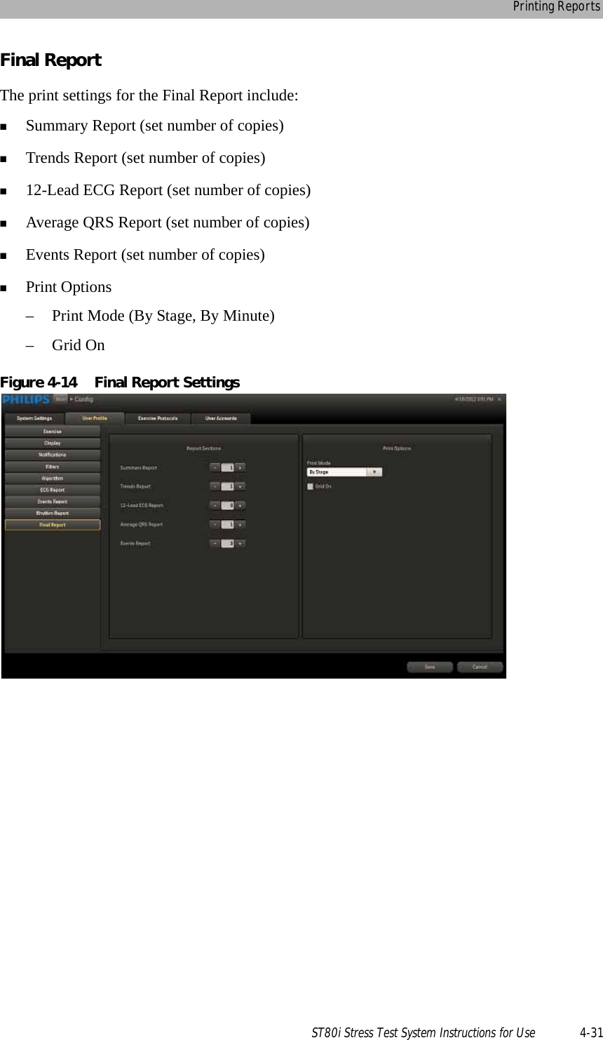
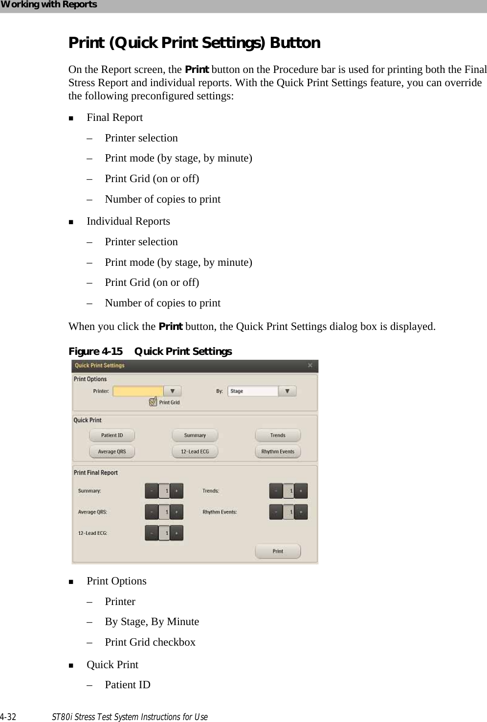
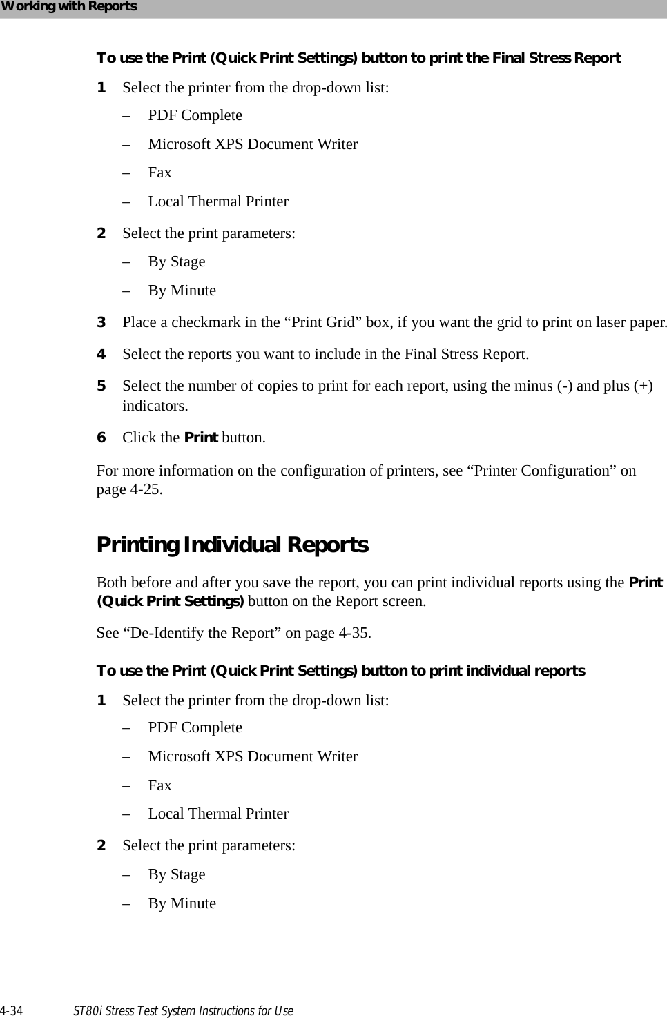
![Printing ReportsST80i Stress Test System Instructions for Use 4-33– Average QRS–Summary– 12-Lead ECG–Trends– Rhythm EventsPrint Final Report– Summary [number of copies]– Average QRS [number of copies]– 12-Lead ECG [number of copies]– Trends [number of copies]– Rhythm Events [number of copies]Print buttonNOTE Regardless of which option you choose, a Summary Report will always be printed on the first page of a final report. You have the option to de-identify or hide a patient's name on individual to final reports before printing. See “De-Identify the Report” on page 4-35 for how to protect a patient's confidential information when printing individual and final patient reports.Printing the Final ReportThe Final Stress Report includes:Summary ReportNOTE The Summary Report cannot be printed without patient demographics. Trends Report12-Lead ECG ReportAverage QRS ReportRhythm Events ReportWhen you log into ST80i, the active settings of the filters are from a stored default set associated with your log-in credentials. The same filter settings apply to both displayed and printed waveforms. The filter settings are printed with the report. NOTE A Patient ID Report is printed at the beginning of each stress test and also in the Final Stress Report.To de-identify the report, see See “De-Identification” on page 3-46.](https://usermanual.wiki/Philips-Medical-Systems-North-America/ST80IAIM/User-Guide-1723687-Page-153.png)
![Exporting Reports (Export Exam)ST80i Stress Test System Instructions for Use 4-47ST80i file names are of the form: --- procedure in development--SV_PatientID[Date+Time]FirstName_MiddleInitial_LastName.pdfwhereSV - required AppName formatPatientID - required Patient identification number or MRN (if provided) [Date+Time] - requiredThe date and time shown is the date and time that the study was acquired. Date format: YYYYMMDDTime format: HHMM FirstName - optionalPatient first name MiddleInitial - optionalPatient middle initial LastName- optionalPatient last name To export a report for TraceMasterVue1Save the final report as described in “Saving the Final Stress Report” on page 4-23.2Click Export to save it as a file. If the file is named correctly, it will be exported to the directory specified in the Miscellaneous tab of the User Profile Configuration window for import into TraceMasterVue.3To automatically remove the report from ST80i after export, check Delete exam after export. IMPORTANT! You cannot recover deleted exams! Use this option, if at all, with great caution. ST80i prompts you to confirm this selection. ST80i places a Y next to this report in the Exp column on the Archive screen.](https://usermanual.wiki/Philips-Medical-Systems-North-America/ST80IAIM/User-Guide-1723687-Page-167.png)

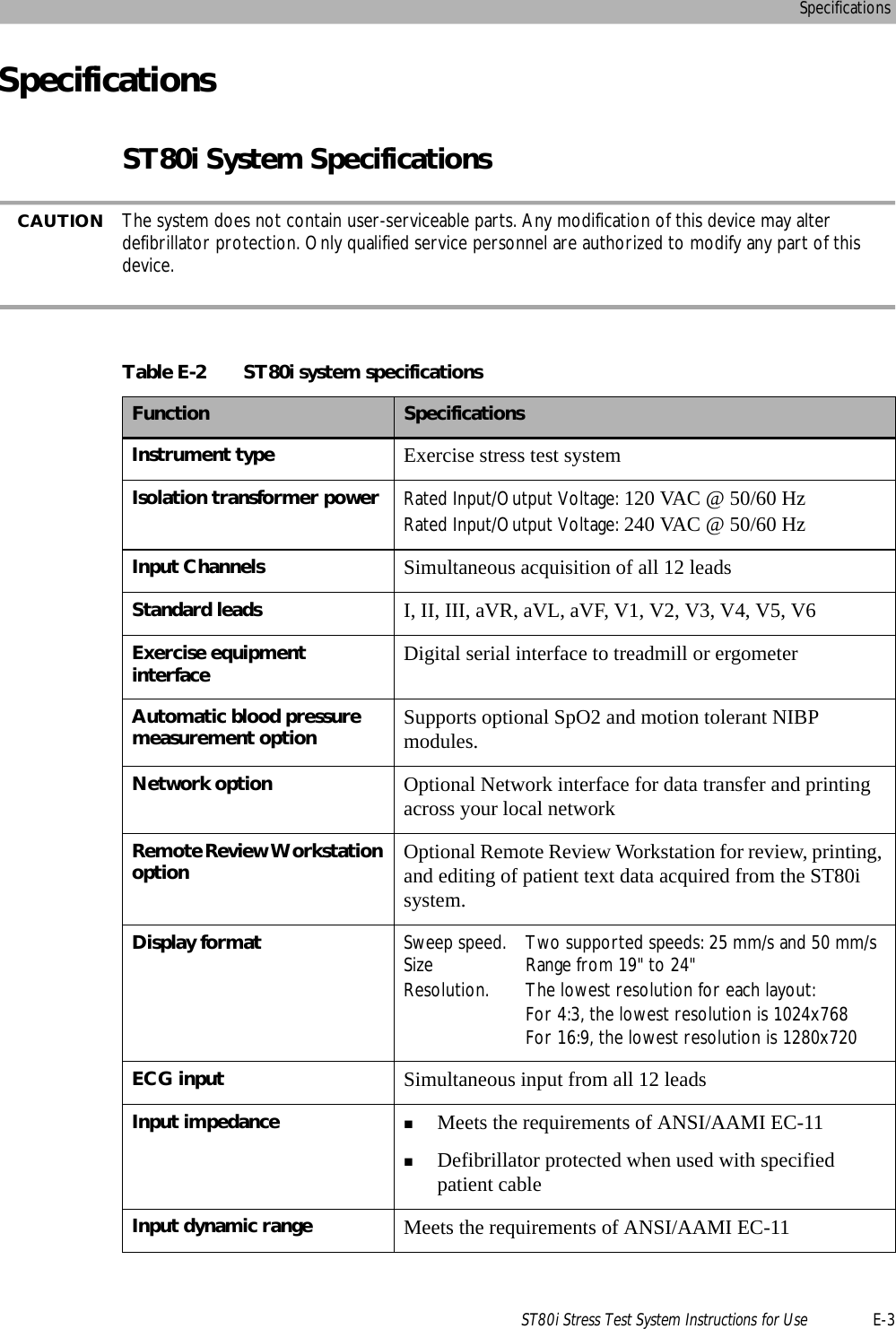
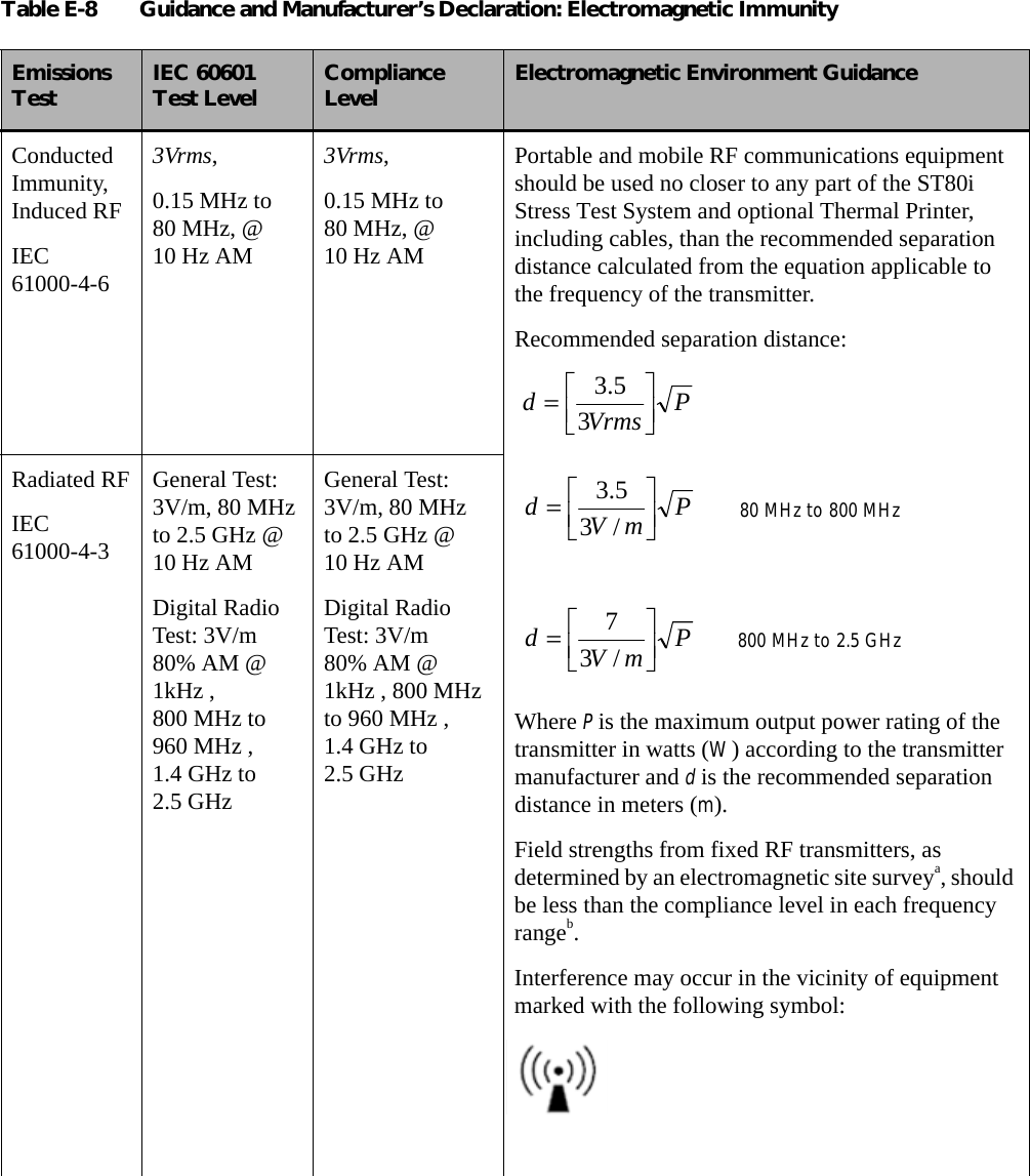
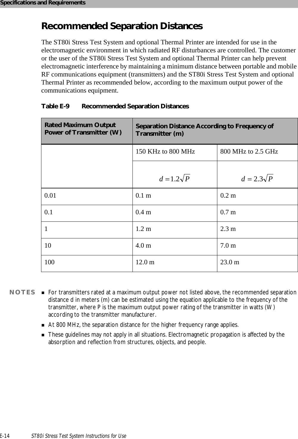
![Electromagnetic Compatibility (EMC)ST80i Stress Test System Instructions for Use E-13a. Field strengths from fixed transmitters, such as base stations for radio (cellular/cordless) telephones and land mobile radios, amateur radios, AM and FM radio broadcast and TV broadcast cannot be predicted theoretically with accuracy. To assess the electromagnetic environment due to fixed RF transmitters, an electromagnetic site survey should be considered. If the measured field strength in the location in which the ST80i Stress Test System and optional Thermal Printer are used exceeds the applicable RF compliance level above, the ST80i Stress Test System and optional Thermal Printer should be observed to verify normal operation. If abnormal performance is observed, additional measures may be necessary, such as reorienting or relocating the ST80i Stress Test System and optional Thermal Printer.b. Over the frequency range 150 kHz to 80 MHz, field strengths should be less than [3] V/m.Electro-surgery InterferenceIEC60601-2-25100W & 300W Cut/Coag, at 450 kHz ± 100 kHz.100W & 300W Cut/Coag, at 450 kHz ± 100 kHz.Table E-8 Guidance and Manufacturer’s Declaration: Electromagnetic ImmunityEmissions Test IEC 60601 Test Level Compliance Level Electromagnetic Environment Guidance](https://usermanual.wiki/Philips-Medical-Systems-North-America/ST80IAIM/User-Guide-1723687-Page-227.png)