Philips Medical Systems North America ST80IAIM Advanced Interface Module User Manual
Philips Medical Systems North America Co. Advanced Interface Module
PQC-ST80iAIM_User manual_Rev1
Instructions for Use
ST80i Stress Test System
ST80i Stress Test System
INSTRUCTIONS FOR USE
Edition 1
June 2012

Notices
PN 453564XXXXXX
June 2012
Edition 1
Printed in the USA
Edition History
Edition 1, June 2012
Applicable to ST80i, version
A01.00 and later.
Philips Medical Systems shall not
be liable for errors contained herein
or for incidental or consequential
damages in connection with the
furnishing, performance, or use of
this material.
Copyright
Copyright © 2012
Koninklijke Philips Electronics
N.V. All rights are reserved.
Andover, MA 01810-1099 USA
(978) 687-1501
Warranty
Philips Medical Systems reserves
the right to make changes to both
this Instructions for Use and to the
product that it describes. Product
specifications are subject to change
without notice.
Nothing contained within this
Instructions for Use is intended as
any offer, warranty, promise, or
contractual condition, and must not
be taken as such.
Responsibility of Manufacturer
Philips Medical Systems only
considers itself responsible for any
effects on safety, reliability, and
performance of the StressVue
system if:
– assembly operations, exten-
sions, re-adjustments, modifica-
tions or repairs are done by
persons authorized by Philips
Medical Systems, and
– the electrical installation of the
relevant room or vehicle
complies with the IEC or
national requirements, and
– the instrument is used according
to the instructions for use
presented in this manual.
Authorized EU-representative
Philips Medizin Systeme
Böblingen GmbH
Hewlett Packard Str. 2
71034 Böblingen
Germany
European Directives
This product consists of hardware
and software. The hardware carries
the CE mark based on the
declarations provided in the User’s
Guide for the IT hardware.
The ST80i software, the wireless
patient module, and the Philips
thermal printer are class IIa medical
devices under the Medical Device
Directive 93/42/EEC and carry
the 0123 mark accordingly.
CAUTION
THIS PRODUCT IS NOT
INTENDED FOR HOME USE. IN
THE U.S., FEDERAL LAW
RESTRICTS THIS DEVICE TO
SALE ON OR BY THE ORDER
OF A PHYSICIAN.
Responsibility of Customer
The user of this product is
responsible for ensuring the
implementation of a satisfactory
maintenance schedule. Failure to do
so may cause undue failure and
possible health hazards.
Global Medical Device
Nomenclature (GMDN)
The 5-digit GMDN code adjacent to
the symbol is defined in the EN ISO
15225.
WARNINGS
As with all electronic equipment,
Radio Frequency (RF) interference
between the ST80i system and any
existing RF transmitting or
receiving equipment at the
installation site, including
electrosurgical equipment, should
be evaluated carefully and any
limitations noted before the
equipment is placed in service.
Radio frequency generation from
electrosurgical equipment and close
proximity transmitters may
seriously degrade performance.
Philips Medical Systems assumes
no liability for failure resulting from
RF interference between Philips
Medical Systems medical
electronics and any radio frequency
generating equipment at levels
exceeding those established by
applicable standards.
Use of accessories other than those
recommended by Philips Medical
Systems may compromise product
performance.
Trademarks
Windows is a registered trademark
of Microsoft Corporation.
All other brand and product names
are trademarks or registered
trademarks of their respective
companies.
GMDN 36145

Chapter 1Contents
i
Safety Summary
Conventions Used in the Instructions for Use. . . . . . . . . . . . . . . . . . . i
Symbols Marked on the ST80i System . . . . . . . . . . . . . . . . . . . . . . . i
Symbols Marked on the ST80i System Packaging . . . . . . . . . . . . . . iii
Disposal Information . . . . . . . . . . . . . . . . . . . . . . . . . . . . . . . . . . . . iii
Important Patient and Safety Information . . . . . . . . . . . . . . . . . . . . iv
Safety Information for the ST80i Stress Test System . . . . . . . . iv
Warning Statements for the ST80i System . . . . . . . . . . . . . . . iv
Caution Statements for the ST80i System . . . . . . . . . . . . . . . vii
Important Notes about the ST80i System . . . . . . . . . . . . . . . viii
Safety Information for the Medical Isolation Transformer. . . . . ix
Warning Statements about the Medical Isolation Transformer ix
Caution Statements about the Medical Isolation Transformer ix
Important Notes about the Medical Isolation Transformer. . . ix
Safety Information for the Advanced Interface Module . . . . . . .x
Caution Statements for the Advanced Interface Module . . . . .x
Important Notes about the Advanced Interface Module . . . . . .x
Safety Information for the Wireless Patient Interface Module . xi
Warnings about the Wireless Patient Interface Module . . . . . xi
Caution Statements for the Wireless Patient Interface Module xii
Important Notes about the Wireless Patient Interface Module xiii
Security Recommendations . . . . . . . . . . . . . . . . . . . . . . . . . . . . . . .xv
The Philips ST80i Stress Test System . . . . . . . . . . . . . . . . . . . . . . xvii
Intended Use . . . . . . . . . . . . . . . . . . . . . . . . . . . . . . . . . . . . . . xvii
Indications for Use. . . . . . . . . . . . . . . . . . . . . . . . . . . . . . . . . . xvii
Contraindications . . . . . . . . . . . . . . . . . . . . . . . . . . . . . . . . . . .xvii
The CAlg-STR Exercise ECG Analysis Algorithm . . . . . . . . . . . xviii
Intended Use . . . . . . . . . . . . . . . . . . . . . . . . . . . . . . . . . . . . . xviii
Indications for Use. . . . . . . . . . . . . . . . . . . . . . . . . . . . . . . . . xviii
Chapter 1. About the Philips ST80i Stress Test System
Overview . . . . . . . . . . . . . . . . . . . . . . . . . . . . . . . . . . . . . . . . . . . . . 1-2
About ST80i Documentation. . . . . . . . . . . . . . . . . . . . . . . . . . . . . . 1-3
Available Documentation . . . . . . . . . . . . . . . . . . . . . . . . . . . . . 1-3
Conventions Used in this Guide . . . . . . . . . . . . . . . . . . . . . . . . 1-4
How to Use this Guide . . . . . . . . . . . . . . . . . . . . . . . . . . . . . . . 1-4
Getting Help Using ST80i. . . . . . . . . . . . . . . . . . . . . . . . . . . . . 1-5

Table of Contents
ii ST80i Stress Test System Instructions for Use
Chapter 2. An Overview of the ST80i Stress Test System
User Accounts . . . . . . . . . . . . . . . . . . . . . . . . . . . . . . . . . . . . . . . . . 2-3
Starting the Application . . . . . . . . . . . . . . . . . . . . . . . . . . . . . . 2-3
User Profile . . . . . . . . . . . . . . . . . . . . . . . . . . . . . . . . . . . . . . . . 2-4
ST80i Test Screen . . . . . . . . . . . . . . . . . . . . . . . . . . . . . . . . . . . . . . 2-5
Title Bar. . . . . . . . . . . . . . . . . . . . . . . . . . . . . . . . . . . . . . . . . . . 2-6
Procedure Bar . . . . . . . . . . . . . . . . . . . . . . . . . . . . . . . . . . . . . . 2-8
Toolbar. . . . . . . . . . . . . . . . . . . . . . . . . . . . . . . . . . . . . . . . . . . . 2-9
Waveform Screen . . . . . . . . . . . . . . . . . . . . . . . . . . . . . . . . . . . 2-9
Side Panel . . . . . . . . . . . . . . . . . . . . . . . . . . . . . . . . . . . . . . . . . . . 2-10
Heart Rate bpm . . . . . . . . . . . . . . . . . . . . . . . . . . . . . . . . . . . . 2-11
Target Heart Rate (130). . . . . . . . . . . . . . . . . . . . . . . . . . . . . . 2-11
Max (220) . . . . . . . . . . . . . . . . . . . . . . . . . . . . . . . . . . . . . . . . 2-12
BP mmhg. . . . . . . . . . . . . . . . . . . . . . . . . . . . . . . . . . . . . . . . . 2-12
Previous BP mmhg . . . . . . . . . . . . . . . . . . . . . . . . . . . . . . . . . 2-12
SpO2 . . . . . . . . . . . . . . . . . . . . . . . . . . . . . . . . . . . . . . . . . . . . 2-12
Double Product (HR*BP) . . . . . . . . . . . . . . . . . . . . . . . . . . . . 2-13
About METS. . . . . . . . . . . . . . . . . . . . . . . . . . . . . . . . . . . . . 2-13
About ST X mm – by Zoom Lead ) . . . . . . . . . . . . . . . . . . 2-13
Treadmill Speed, Grade % . . . . . . . . . . . . . . . . . . . . . . . . . . . 2-13
Treadmill Button. . . . . . . . . . . . . . . . . . . . . . . . . . . . . . . . . . 2-14
Ergometer Button . . . . . . . . . . . . . . . . . . . . . . . . . . . . . . . . . 2-14
Using the Toolbar Icons. . . . . . . . . . . . . . . . . . . . . . . . . . . . . . . . . 2-14
Waveform . . . . . . . . . . . . . . . . . . . . . . . . . . . . . . . . . . . . . . . . 2-17
Hide/Show View . . . . . . . . . . . . . . . . . . . . . . . . . . . . . . . . . . . 2-17
About the Lead Map. . . . . . . . . . . . . . . . . . . . . . . . . . . . . . . 2-18
About the Zoom ST . . . . . . . . . . . . . . . . . . . . . . . . . . . . . . . 2-19
About the ST Map . . . . . . . . . . . . . . . . . . . . . . . . . . . . . . . . 2-20
About Trend View . . . . . . . . . . . . . . . . . . . . . . . . . . . . . . . . 2-21
About HR/METS . . . . . . . . . . . . . . . . . . . . . . . . . . . . . . . . . 2-22
About ST J+ mV. . . . . . . . . . . . . . . . . . . . . . . . . . . . . . . . . . 2-22
About BP . . . . . . . . . . . . . . . . . . . . . . . . . . . . . . . . . . . . . . . 2-23
About the Average Complex Display. . . . . . . . . . . . . . . . . . 2-23
Freeze . . . . . . . . . . . . . . . . . . . . . . . . . . . . . . . . . . . . . . . . . . . 2-24
Recording an Event. . . . . . . . . . . . . . . . . . . . . . . . . . . . . . . . . 2-24
Recording RPE . . . . . . . . . . . . . . . . . . . . . . . . . . . . . . . . . . . . 2-26
Note . . . . . . . . . . . . . . . . . . . . . . . . . . . . . . . . . . . . . . . . . . . . . 2-27
Compare . . . . . . . . . . . . . . . . . . . . . . . . . . . . . . . . . . . . . . . . . 2-27
Page . . . . . . . . . . . . . . . . . . . . . . . . . . . . . . . . . . . . . . . . . . . . . 2-28
Gear (Quick Settings) . . . . . . . . . . . . . . . . . . . . . . . . . . . . . . . 2-29
Filter . . . . . . . . . . . . . . . . . . . . . . . . . . . . . . . . . . . . . . . . . . . 2-29
Display . . . . . . . . . . . . . . . . . . . . . . . . . . . . . . . . . . . . . . . . . 2-30
Rhythm Print. . . . . . . . . . . . . . . . . . . . . . . . . . . . . . . . . . . . . 2-31
Sync Out . . . . . . . . . . . . . . . . . . . . . . . . . . . . . . . . . . . . . . . . 2-31

Table of Contents
ST80i Stress Test System Instructions for Use iii
Chapter 3. The Patient Session
Overview . . . . . . . . . . . . . . . . . . . . . . . . . . . . . . . . . . . . . . . . . . . . . 3-1
Using the Patient Worklist . . . . . . . . . . . . . . . . . . . . . . . . . . . . . . . . 3-4
Worklist Tab . . . . . . . . . . . . . . . . . . . . . . . . . . . . . . . . . . . . . . . 3-5
Patient Information Management. . . . . . . . . . . . . . . . . . . . . . 3-5
Patient Information Fields . . . . . . . . . . . . . . . . . . . . . . . . . . . 3-6
Add a New Patient to the Worklist. . . . . . . . . . . . . . . . . . . . . 3-6
Find a Patient . . . . . . . . . . . . . . . . . . . . . . . . . . . . . . . . . . . . . 3-7
Edit Patient Information . . . . . . . . . . . . . . . . . . . . . . . . . . . . . 3-7
Delete a Patient Name . . . . . . . . . . . . . . . . . . . . . . . . . . . . . . 3-8
Download Preregistered Patient Information. . . . . . . . . . . . . 3-9
Review a Previous ECG . . . . . . . . . . . . . . . . . . . . . . . . . . . . . 3-9
Select a Patient . . . . . . . . . . . . . . . . . . . . . . . . . . . . . . . . . . .3-10
Remote Find Tab . . . . . . . . . . . . . . . . . . . . . . . . . . . . . . . . . . . 3-10
Before the Patient Session . . . . . . . . . . . . . . . . . . . . . . . . . . . . . . . 3-12
Wireless Patient Interface Module (PIM) . . . . . . . . . . . . . . . . 3-12
Checking the Treadmill/Ergometer Connection. . . . . . . . . . 3-14
Starting a Patient Session. . . . . . . . . . . . . . . . . . . . . . . . . . . . . . . . 3-15
Select the Patient. . . . . . . . . . . . . . . . . . . . . . . . . . . . . . . . . . . 3-15
Select the Wireless PIM . . . . . . . . . . . . . . . . . . . . . . . . . . . . . 3-16
Preparing the Patient . . . . . . . . . . . . . . . . . . . . . . . . . . . . . . . . . . . 3-17
Instructing the Patient about the Test . . . . . . . . . . . . . . . . . . . 3-17
Preparing the Skin. . . . . . . . . . . . . . . . . . . . . . . . . . . . . . . . . . 3-17
Attaching the Electrodes/Lead Wires . . . . . . . . . . . . . . . . . . . 3-18
Change from Limb Lead to Mason-Likar . . . . . . . . . . . . . .3-20
Connecting the Patient to the Wireless PIM. . . . . . . . . . . . . 3-21
Wireless PIM Button Functions . . . . . . . . . . . . . . . . . . . . . .3-21
Checking the Lead Map . . . . . . . . . . . . . . . . . . . . . . . . . . . . . 3-21
Checking Signal Quality . . . . . . . . . . . . . . . . . . . . . . . . . . . . . 3-22
Filtering. . . . . . . . . . . . . . . . . . . . . . . . . . . . . . . . . . . . . . . . .3-24
Sync Output . . . . . . . . . . . . . . . . . . . . . . . . . . . . . . . . . . . . . 3-24
Pre Exercise Phase . . . . . . . . . . . . . . . . . . . . . . . . . . . . . . . . . 3-26
Static ECG Resting Interpretation . . . . . . . . . . . . . . . . . . . .3-26
NIBP & SpO2. . . . . . . . . . . . . . . . . . . . . . . . . . . . . . . . . . . . 3-28
Override NIBP and SpO2. . . . . . . . . . . . . . . . . . . . . . . . . . . 3-28
Starting the Patient on the Treadmill or Ergometer . . . . . . . 3-29
Exercise Phase. . . . . . . . . . . . . . . . . . . . . . . . . . . . . . . . . . . . . 3-30
Conducting the Exercise Stress Test. . . . . . . . . . . . . . . . . . .3-31
Monitoring the Patient . . . . . . . . . . . . . . . . . . . . . . . . . . . . .3-31
Changing to Another Protocol . . . . . . . . . . . . . . . . . . . . . . . 3-32
Rhythm Print. . . . . . . . . . . . . . . . . . . . . . . . . . . . . . . . . . . . . 3-33
12-Leads Print. . . . . . . . . . . . . . . . . . . . . . . . . . . . . . . . . . . . 3-33
Controlling the Treadmill or Ergometer. . . . . . . . . . . . . . . .3-33
Notifications and Alerts . . . . . . . . . . . . . . . . . . . . . . . . . . . . 3-34
Ending the Exercise Phase . . . . . . . . . . . . . . . . . . . . . . . . . . . 3-36
Recovery Phase . . . . . . . . . . . . . . . . . . . . . . . . . . . . . . . . . . . . 3-36

Table of Contents
iv ST80i Stress Test System Instructions for Use
Report Phase . . . . . . . . . . . . . . . . . . . . . . . . . . . . . . . . . . . . . . 3-38
Post-Recovery. . . . . . . . . . . . . . . . . . . . . . . . . . . . . . . . . . . . 3-38
Final Report Manager. . . . . . . . . . . . . . . . . . . . . . . . . . . . . . 3-38
Global Interpretive Settings . . . . . . . . . . . . . . . . . . . . . . . . . . 3-39
DXL Algorithm . . . . . . . . . . . . . . . . . . . . . . . . . . . . . . . . . . 3-39
CALg Templates. . . . . . . . . . . . . . . . . . . . . . . . . . . . . . . . . . 3-39
Pace-Pulse Detection . . . . . . . . . . . . . . . . . . . . . . . . . . . . . . 3-39
Printing During the Stress Test . . . . . . . . . . . . . . . . . . . . . . . . . . . 3-41
Printer Configuration . . . . . . . . . . . . . . . . . . . . . . . . . . . . . . . 3-41
Print Options . . . . . . . . . . . . . . . . . . . . . . . . . . . . . . . . . . . . . . 3-43
Real-Time ECG . . . . . . . . . . . . . . . . . . . . . . . . . . . . . . . . . . 3-43
12-Lead Resting ECG Report. . . . . . . . . . . . . . . . . . . . . . . . 3-43
Stage Printout and Event Printout . . . . . . . . . . . . . . . . . . . . 3-44
Continuous Rhythm Strip. . . . . . . . . . . . . . . . . . . . . . . . . . . 3-45
De-Identification . . . . . . . . . . . . . . . . . . . . . . . . . . . . . . . . . 3-45
Ending the Patient Session. . . . . . . . . . . . . . . . . . . . . . . . . . . . . . . 3-47
Starting a New Patient Session . . . . . . . . . . . . . . . . . . . . . . . . 3-47
Exiting the Application . . . . . . . . . . . . . . . . . . . . . . . . . . . . . . 3-47
Chapter 4. Working with Reports
Overview . . . . . . . . . . . . . . . . . . . . . . . . . . . . . . . . . . . . . . . . . . . . . 4-1
Report Phase . . . . . . . . . . . . . . . . . . . . . . . . . . . . . . . . . . . . . . . . . . 4-3
Post-Recovery Phase. . . . . . . . . . . . . . . . . . . . . . . . . . . . . . . . . 4-3
Report Screen. . . . . . . . . . . . . . . . . . . . . . . . . . . . . . . . . . . . . . . . . . 4-4
Title Bar. . . . . . . . . . . . . . . . . . . . . . . . . . . . . . . . . . . . . . . . . . . 4-6
Procedure Bar . . . . . . . . . . . . . . . . . . . . . . . . . . . . . . . . . . . . . . 4-7
Change (J+) Point. . . . . . . . . . . . . . . . . . . . . . . . . . . . . . . . . . 4-7
Save. . . . . . . . . . . . . . . . . . . . . . . . . . . . . . . . . . . . . . . . . . . . . 4-7
Export . . . . . . . . . . . . . . . . . . . . . . . . . . . . . . . . . . . . . . . . . . 4-8
Print. . . . . . . . . . . . . . . . . . . . . . . . . . . . . . . . . . . . . . . . . . . . . 4-9
Confirm. . . . . . . . . . . . . . . . . . . . . . . . . . . . . . . . . . . . . . . . . . 4-9
Replay. . . . . . . . . . . . . . . . . . . . . . . . . . . . . . . . . . . . . . . . . . 4-10
Real-Time ECG for One Lead . . . . . . . . . . . . . . . . . . . . . . . . 4-12
Print Options. . . . . . . . . . . . . . . . . . . . . . . . . . . . . . . . . . . . . 4-12
Current Blood Pressure. . . . . . . . . . . . . . . . . . . . . . . . . . . . . 4-12
Final Stress Report Overview . . . . . . . . . . . . . . . . . . . . . . . . . . . . 4-13
Report Screen Tabs . . . . . . . . . . . . . . . . . . . . . . . . . . . . . . . . . . . . 4-15
Summary Report . . . . . . . . . . . . . . . . . . . . . . . . . . . . . . . . . . . 4-15
Tabular Report. . . . . . . . . . . . . . . . . . . . . . . . . . . . . . . . . . . . . 4-17
Trend Graph Report . . . . . . . . . . . . . . . . . . . . . . . . . . . . . . . . 4-18
Averages Report . . . . . . . . . . . . . . . . . . . . . . . . . . . . . . . . . . . 4-19
Events Report . . . . . . . . . . . . . . . . . . . . . . . . . . . . . . . . . . . . . 4-20
Resting ECG Report . . . . . . . . . . . . . . . . . . . . . . . . . . . . . . . . 4-23
Full Disclose Report . . . . . . . . . . . . . . . . . . . . . . . . . . . . . . . . 4-24
Saving the Final Stress Report. . . . . . . . . . . . . . . . . . . . . . . . . . . . 4-24
Printing Reports. . . . . . . . . . . . . . . . . . . . . . . . . . . . . . . . . . . . . . . 4-26

Table of Contents
ST80i Stress Test System Instructions for Use v
Printer Configuration. . . . . . . . . . . . . . . . . . . . . . . . . . . . . . . . 4-26
Print Report Settings . . . . . . . . . . . . . . . . . . . . . . . . . . . . . . . . 4-28
ECG Report . . . . . . . . . . . . . . . . . . . . . . . . . . . . . . . . . . . . .4-29
Events Report . . . . . . . . . . . . . . . . . . . . . . . . . . . . . . . . . . . . 4-30
Rhythm Report . . . . . . . . . . . . . . . . . . . . . . . . . . . . . . . . . . .4-31
Final Report . . . . . . . . . . . . . . . . . . . . . . . . . . . . . . . . . . . . . 4-32
Print (Quick Print Settings) Button. . . . . . . . . . . . . . . . . . . . . 4-33
Printing the Final Report. . . . . . . . . . . . . . . . . . . . . . . . . . . . . 4-34
Printing Individual Reports. . . . . . . . . . . . . . . . . . . . . . . . . . . 4-35
Post-Recovery ECG Printing . . . . . . . . . . . . . . . . . . . . . . . . . 4-37
De-Identify the Report . . . . . . . . . . . . . . . . . . . . . . . . . . . . . . 4-37
Working with Archived Reports . . . . . . . . . . . . . . . . . . . . . . . . . . 4-38
Report (Stress Study) Database. . . . . . . . . . . . . . . . . . . . . . . . 4-38
Database Configuration . . . . . . . . . . . . . . . . . . . . . . . . . . . .4-39
Patient Reports . . . . . . . . . . . . . . . . . . . . . . . . . . . . . . . . . . . . 4-40
Search for Reports . . . . . . . . . . . . . . . . . . . . . . . . . . . . . . . .4-42
Confirm a Report . . . . . . . . . . . . . . . . . . . . . . . . . . . . . . . . . 4-42
Transfer Reports . . . . . . . . . . . . . . . . . . . . . . . . . . . . . . . . . . 4-42
Delete Reports . . . . . . . . . . . . . . . . . . . . . . . . . . . . . . . . . . .4-43
View a Report . . . . . . . . . . . . . . . . . . . . . . . . . . . . . . . . . . . . 4-44
Replay a Report . . . . . . . . . . . . . . . . . . . . . . . . . . . . . . . . . . 4-44
Viewing Reports Saved as PDF Files . . . . . . . . . . . . . . . . . . . 4-45
Exporting Reports (Export Exam) . . . . . . . . . . . . . . . . . . . . . . . . 4-45
External Storage of Stress Study data . . . . . . . . . . . . . . . . . . . 4-46
ECG Export Destination Sites. . . . . . . . . . . . . . . . . . . . . . . . . 4-46
Exporting Reports to an ECG Management System. . . . . . . . 4-47
File Naming Conventions. . . . . . . . . . . . . . . . . . . . . . . . . . . 4-47
Exporting Reports for Use with the ECG Connect Option - .4-49
Importing ECGs . . . . . . . . . . . . . . . . . . . . . . . . . . . . . . . . . . . 4-49
Working with Batch Reports . . . . . . . . . . . . . . . . . . . . . . . . . . . . . 4-49
Reviewing and Saving Multiple Reports . . . . . . . . . . . . . . . . 4-50
Deleting Multiple Reports (Delete Exam) . . . . . . . . . . . . . . . 4-50
Printing Multiple Reports (Print Reports). . . . . . . . . . . . . . . . 4-51
. . . . . . . . . . . . . . . . . . . . . . . . . . . . . . . . . . . . . . . . . . . . . . . . . 4-51
Chapter 5. Maintaining the ST80i System
Precautions. . . . . . . . . . . . . . . . . . . . . . . . . . . . . . . . . . . . . . . . . . . . 5-1
Cleaning the ST80i System . . . . . . . . . . . . . . . . . . . . . . . . . . . . . . . 5-2
Cleaning the Printer . . . . . . . . . . . . . . . . . . . . . . . . . . . . . . . . . . . . . 5-4
Cleaning the Equipment. . . . . . . . . . . . . . . . . . . . . . . . . . . . . . . . . . 5-4
Appendix A. Troubleshooting and Contacting the
Response Center
Troubleshooting ST80i Issues . . . . . . . . . . . . . . . . . . . . . . . . . . . . .A-2

Table of Contents
vi ST80i Stress Test System Instructions for Use
Contacting Technical Support . . . . . . . . . . . . . . . . . . . . . . . . . . . .A-10
Philips Healthcare Customer Care Solution Center . . . . . . . .A-10
North America . . . . . . . . . . . . . . . . . . . . . . . . . . . . . . . . . . .A-10
South America . . . . . . . . . . . . . . . . . . . . . . . . . . . . . . . . . . .A-10
Europe. . . . . . . . . . . . . . . . . . . . . . . . . . . . . . . . . . . . . . . . . .A-10
Asia Pacific. . . . . . . . . . . . . . . . . . . . . . . . . . . . . . . . . . . . . .A-12
Appendix B. Protocol Reference
Bruce Protocol . . . . . . . . . . . . . . . . . . . . . . . . . . . . . . . . . . . . . . . . .B-2
Modified Bruce . . . . . . . . . . . . . . . . . . . . . . . . . . . . . . . . . . . . . . . .B-3
Balke Protocol . . . . . . . . . . . . . . . . . . . . . . . . . . . . . . . . . . . . . . . . .B-4
Ellestad Protocol . . . . . . . . . . . . . . . . . . . . . . . . . . . . . . . . . . . . . . . B-5
Naughton Protocol. . . . . . . . . . . . . . . . . . . . . . . . . . . . . . . . . . . . . . B-6
Pharmacological Protocol . . . . . . . . . . . . . . . . . . . . . . . . . . . . . . . . B-7
Low Ramp Protocol. . . . . . . . . . . . . . . . . . . . . . . . . . . . . . . . . . . . . B-8
Medium Ramp Protocol. . . . . . . . . . . . . . . . . . . . . . . . . . . . . . . . . . B-9
High Ramp Protocol . . . . . . . . . . . . . . . . . . . . . . . . . . . . . . . . . . . B-10
USAF/SAM 2.0 Protocol. . . . . . . . . . . . . . . . . . . . . . . . . . . . . . . .B-11
USAF/SAM 3.3 Protocol. . . . . . . . . . . . . . . . . . . . . . . . . . . . . . . .B-11
Cycle (Ergometer) Protocol. . . . . . . . . . . . . . . . . . . . . . . . . . . . . .B-12
Astrand Protocol . . . . . . . . . . . . . . . . . . . . . . . . . . . . . . . . . . . . . . B-13
Appendix C. Configuring and Using the Printer
ST80i Thermal Printer. . . . . . . . . . . . . . . . . . . . . . . . . . . . . . . . . . .C-1
Thermal Printer Dimensions and Specifications. . . . . . . . . . . .C-2
Loading the Thermal Printer Paper. . . . . . . . . . . . . . . . . . . . . .C-6
Setting Up the Thermal Printer. . . . . . . . . . . . . . . . . . . . . . . . .C-7
Maintaining the Thermal Printer . . . . . . . . . . . . . . . . . . . . . . .C-9
Inspecting the ST80i Thermal Printer . . . . . . . . . . . . . . . . . .C-9
Cleaning the ST80i Thermal Printer . . . . . . . . . . . . . . . . . . .C-9
Testing Printer Operation . . . . . . . . . . . . . . . . . . . . . . . . . . .C-10
About the Supported LaserJet Printers . . . . . . . . . . . . . . . . . . . . .C-11
Appendix D. Ordering Options and Parts
Supplies and Ordering Information. . . . . . . . . . . . . . . . . . . . . . . . .D-1
Optional Parts and Accessories. . . . . . . . . . . . . . . . . . . . . . . . .D-1
Support Parts. . . . . . . . . . . . . . . . . . . . . . . . . . . . . . . . . . . . . . .D-3
Appendix E. Specifications and Requirements
ST80i System Requirements . . . . . . . . . . . . . . . . . . . . . . . . . . . . . . E-1
Specifications. . . . . . . . . . . . . . . . . . . . . . . . . . . . . . . . . . . . . . . . . . E-4
ST80i System Specifications . . . . . . . . . . . . . . . . . . . . . . . . . . E-4

Table of Contents
ST80i Stress Test System Instructions for Use vii
Medical Isolation Transformer Specifications . . . . . . . . . . . . . E-6
ST80i Thermal Printer Specifications. . . . . . . . . . . . . . . . . . . . E-7
Supported Treadmills and Ergometers . . . . . . . . . . . . . . . . . . . . . . E-8
Electromagnetic Compatibility (EMC) . . . . . . . . . . . . . . . . . . . . . . E-8
Accessories and Cables Warning . . . . . . . . . . . . . . . . . . . . . . . E-9
Guidance and Manufacturer’s Declaration: Electromagnetic Emissions E-10
Guidance and Manufacturer’s Declaration: Electromagnetic Immunity E-11
Recommended Separation Distances . . . . . . . . . . . . . . . . . . . E-15

Table of Contents
viii ST80i Stress Test System Instructions for Use
i
Safety Summary
This chapter provides important safety information related to the use of the ST80i Stress Test
System.
US FEDERAL LAW RESTRICTS THIS DEVICE TO SALE BY OR ON THE ORDER OF
A PHYSICIAN.
Conventions Used in the Instructions for Use
The following conventions are used in the ST80i Stress Test System Instructions for Use, this
guide.
WARNING Warning statements describe conditions or actions that may result in personal injury or
loss of life.
CAUTION Caution statements describe conditions or actions that may result in damage to equipment or
software.
NOTE Notes contain additional important information about a topic.
Refer to the manual(s) accompanying the ST80i Stress Test System that pertain to the
system’s computer hardware for additional definitions of symbols that may be present.
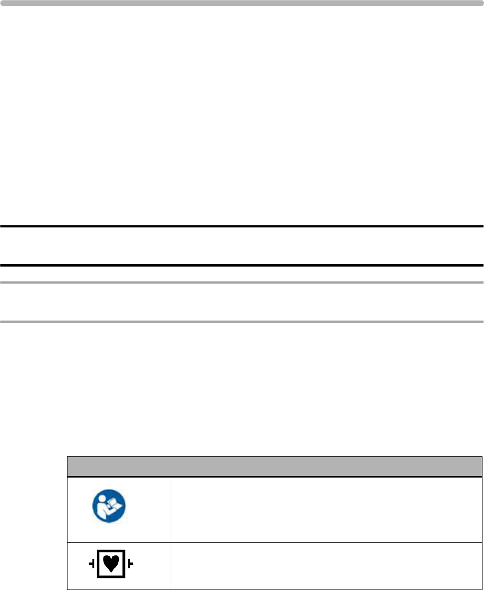
Symbols Marked on the ST80i System
Symbol Description
Attention. See the ST80i Instructions for Use and other product
documentation for information.
For information about the Advanced Interface Module, see
“Important Notes about the Advanced Interface Module” on page x.
ECG physio isolation is type CF, defibrillator proof. Suitable for all
patient applications including direct cardiac application. System is
in continuous operation.
Safety Summary
ii ST80i Stress Test System Instructions for Use
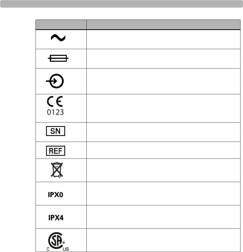
Indicates that the system is receiving alternating currents.
Fuse
The connector near this symbol receives an incoming signal.
CE mark.
The number next to this symbol is the serial number of the system.
The number next to this symbol is the product model number of the
system.
Dispose of in accordance with the requirements of your country.
An International Protection Rating of “IPX0” indicates that the
equipment has no special protection against moisture ingress. The
ST80i System carries this rating.
An International Protection Rating of “IPX4” indicates that the
equipment is protected against slashing water from any angle. The
Wireless Patient Interface Module carries this rating.
Canadian Standards Association (CSA) Certification Mark.
Indicates that the product is certified for both the U.S. and Canadian
markets, to the applicable U.S. and Canadian standards.
Symbol Description
Symbols Marked on the ST80i System Packaging
ST80i Stress Test System Instructions for Use iii
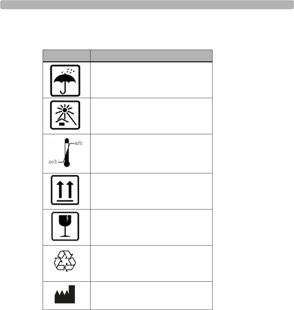
Symbols Marked on the ST80i System Packaging
Disposal Information
This product consists of devices that may contain mercury, which must be recycled or
disposed of in accordance with local, state, or federal laws. (Within this system the backlight
lamps in the monitor display may contain mercury.)
Remove all batteries prior to disposing of any system components. Properly dispose of or
recycle depleted batteries according to local regulations. Then dispose of the device in
accordance with local, state, or federal regulations for equipment containing electronic parts.
Symbol Description
Keep dry.
Keep out of direct sunlight.
Acceptable temperature range.
Move and store packaging this end up.
Fragile.
Recycle the packaging materials after use.
Manufacturer

Safety Summary
iv ST80i Stress Test System Instructions for Use
Important Patient and Safety Information
Patient and safety information is divided into several sections:
ST80i Stress Test System (next section)
Medical isolation transformer (page ix)
Philips advanced interface module (AIM) (page x)
Philips wireless patient interface module (PIM) (page xi)
For information about electromagnetic compatibility (EMC) with surrounding devices, see
“Electromagnetic Compatibility (EMC) - To be finalized” on page E-7 of Appendix E,
“Specifications and Requirements”
Safety Information for the ST80i Stress Test System
The Philips ST80i Stress Test System, when operated with the ST80i AIM, AIM data cable,
ST80i PIM, and lead wires, shall meet all of the EMC requirements specified in the following
standards:
IEC 60601-1:1988 + A1:1991 + A2:1995 Medical Electrical Equipment – Part 1 - General
requirements for basic safety and performance
AAMI EC11:8/2007 - Diagnostic Electrocardiographic Devices
IEC 60601-2-25:1993 + A1:1999 - Particular requirements for the safety of
electrocardiographs
AAMI EC53:12/2008 - ECG cables and leadwires
Warning Statements for the ST80i System
WARNING Failure to follow these warnings could affect both patient and operator safety.
Do not use the ST80i System in the presence of flammable vapors.
Do not use the ST80i System in the presence of explosive gases. AC power connection/
disconnection or electrostatic discharge (ESD) may result in spark occurring in an
environment where explosive gases are used.
Submersion and/or conditions that subject the ST80i System to liquid ingress create a
shock hazard.
When operating the ST80i System, ensure that the system and all other electrical
equipment connected to or near the patient are effectively grounded.
Do not touch accessible connector pins and the patient simultaneously.
The ST80i System has been safety tested with the recommended accessories, peripherals,
and leads, and no hazard was found when the system is operated with cardiac pacemakers
or other stimulators.

Important Patient and Safety Information
ST80i Stress Test System Instructions for Use v
To maintain designed operator and patient safety when assembling a medical electrical
system for use in the patient environment, the responsible organization shall ensure that
peripheral equipment and accessories used that can come in direct patient contact must
comply with the following standards:
– IEC 60601-1-1:2000 aka CAN/CSA-C22.2 No.60601-1-1:02
– EN 60601-1-2:2001 (all parts and particularly clause 19), titled, “Medical electrical
equipment - Part 1-1: General requirements for safety - Collateral Standard: Safety
requirements for medical electrical systems”
– EN 60601-1:2006 (clause 16 and particularly clause 16.6), titled, “Medical electrical
equipment - Part 1: General requirements for basic safety and essential performance”
Connecting multiple medical electrical instruments to the same patient may pose a safety
hazard due to the summation of leakage currents. Any combination of medical electrical
instruments should be evaluated by local safety personnel before being put into service.
For equipment not certified to medical electrical equipment standards that may be used
within the patient vicinity, an appropriately rated isolation transformer is required.
Do not connect to the system any items which are not specified as part of the system.
The PC, LCD, thermal printer, and desk light, purchased as part of a complete system
must be plugged into the medical-grade isolation transformer provided with ST80i.
Plug all accessories used with ST80i into the medical-grade isolation transformer
provided as part of the “software-only” solution.
Do not connect additional Multiple Portable Socket-Outlets (MPSOs) or extension cords
to the system.
The ST80i USB and RS-232 ports should be connected only to treadmills, ergometers, and
NIBP monitors that are certified to meet IEC 60601-1 and are listed as supported devices
in the Instructions for Use. See See “Supported Treadmills and Ergometers” on page 7. of
Appendix E, “Specifications and Requirements”.
The performance and safety of the ST80i System cannot be guaranteed if you use
non-compatible accessories.
Only computers, monitors, and printers approved by a National Certification Body (NCB)
or a Nationally Recognized Testing Laboratory (NRTL) to IEC 60950-1 shall be
connected to the ST80i system. All computer, monitor and printer outputs shall comply
with IEC 60950-1 limited power source requirements.
The use of ST80i with equipment (electrosurgical equipment and some respiration
transducers) that applies high frequency voltage to a patient is not supported and may
produce undesired outputs.
To prevent burns to the patient, remove all ECG electrodes and lead wires prior to the use
of high frequency surgical equipment (including electrosurgical equipment and some
respiration transducers).
Only install Philips software on the ST80i System. The installation or use of software,
security patches, or updates not approved by Philips is strictly prohibited and system
safety and performance are not guaranteed.

Safety Summary
vi ST80i Stress Test System Instructions for Use
Use only shielded LAN cable when connecting the cable to the ST80i LAN port.
Use Philips-approved lead wires with defibrillator protection resistors.
To avoid the possibility of serious injury or death during patient defibrillation, do not
come into contact with the wireless PIM or lead wires. Additionally, proper placement of
defibrillator paddles in relation to the electrodes is required to minimize harm to the
patient.
Do not contact floating electrodes during defibrillation, and avoid touching the lead wires
or conductive surfaces on the trolley during defibrillation.
Conductive parts of the patient lead wires, electrodes, and associated Type CF
connections, should not come into contact with other conductive parts, including earth
ground.
Electrodes of dissimilar metals should not be used.
Check lead wires, the cable between the PC and the treadmill, the cable between the PC
and the NIBP module, the AC adapter, and power cords daily for any worn or cracked
insulation to ensure that no inner conductive material is exposed. Discard worn
accessories and replace them only with Philips accessories.
The ST80i System should only use grounded power cords (three-wire power cords with
grounded plugs) and connect to grounded electrical outlets that are labeled as “Hospital
Only” or “Hospital Grade.” Never adapt a grounded plug to fit an ungrounded outlet by
removing the ground prong.
EMI generated by the ST80i System may cause nearby equipment to fail.
Short-range radio connections are subject to interruption due to interference from other
radio sources in the vicinity, including microwaves, bluetooth devices, and DECT phones.
Outside the frequency band and 5% above and below, i.e. the exclusion band according to
IEC 60601-1-2, the short-range radio connection is immune up to 3V/m in the frequency
range from 80 MHz to 2.5 GHz. Depending on the strength and duration of the
interference, the interruption may occur for an extended period. Any interruption of the
signal due to interference, moving out of range, or for other reasons is indicated via an RF
signal status indicator on both the PIM as well as on the main screen.
If your system includes the trolley, ensure that components are installed securely and that
no items are placed on the trolley that could cause the trolley to become unstable.
The maximum weight to be placed on the optional shelf for a laser printer is 45 pounds.
If your system includes the trolley, always lock the wheel brake when the trolley is not in
motion. Press down on the brake tab to set the brake and lift up on the tab to release the
brake.
Safe removal of the all-in-one display from the trolley requires two people.
Placing or spilling liquids on the trolley may cause electrical safety hazards and/or system
malfunction.
Allow the patient to move freely by:

Important Patient and Safety Information
ST80i Stress Test System Instructions for Use vii
– taking care when dressing the ECG cables so as to minimize the potential tripping
hazard during the stress ECG study process
– securing the patient lead set, power cable, treadmill cable, echo cable, NIBP cable,
and SpO2 cable away from patient’s feet before beginning exercise stage
The ST80i captures and presents data reflecting a patient’s physiological condition that,
when reviewed by a trained physician or clinician, can be useful in determining a
diagnosis. However, the data should not be used as a sole means for determining a
patient’s diagnosis.
Both analog ECG output and TTL sync output are not in real time: there is a delay
between the patient’s physiological activity and the appearance of its representative signal
at the external port. This signal should not be used for analysis.
To get the most accurate interpretation during resting ECG, use traditional limb lead
placement.
For the user’s convenience only, rhythm change notifications are provided when specific
rhythm changes are detected; however, it is the responsibility of the trained healthcare
professional to determine the type of rhythm change and take appropriate action.
Additionally, the healthcare professional should not assume that all rhythm changes will
be detected, and they are responsible for taking action when rhythm changes are observed
on the displayed waveforms and the system fails to provide a notification. It is expected
that only properly trained healthcare professionals working directly under the supervision
of a qualified physician will be operating the ST80i System during testing.
ST80i cannot import ECGs from another vendor’s stress system.
“Simulated ECG” mode must be turned off when testing patients.
If the “Stop Treadmill” GUI button does not respond for any reason, immediately press the
red “Emergency” button on the treadmill handrail.
The interpretive algorithm has been validated only with “standard” lead placement.
If the patient data is found to be incorrect, you may edit the ECG file and can print a new
report.
Entering incorrect NIBP data can cause errors for NIBP-related parameters in reports.
Caution Statements for the ST80i System
CAUTION Caution statements describe conditions or actions that may result in damage to equipment or
software.
The Multiple Portable Socket-Outlet (MPSO) provided with the system shall only be used
for powering equipment which forms part of the system.
Do not pull or stretch patient lead wires as this could result in mechanical and/or electrical
failures. Store patient lead wires after forming them into a loose loop.

Safety Summary
viii ST80i Stress Test System Instructions for Use
Do not attempt to clean the device or patient lead wires by submersion, autoclaving, or
steam cleaning.
Wipe the exterior surface of the device and patient lead wires with a compatible non-
alcohol sterilizing disinfectant, then dry with a clean cloth. See “Cleaning the ST80i
System” on page 5-2 in the “Maintaining the ST80i System” chapter for a list of approved
disenfectants.
Be careful not to damage the display when moving the trolley or when moving other
equipment near trolley.
To prevent possible damage to the device during transport and storage (while in original
packaging), the following environmental conditions must be adhered to:
Storage Temperature Range:
-20°C to 50°C (-4°F to 122°F)
Storage Humidity Range:
10% to 90% (non-condensing)
Storage Pressure (altitude):
Up to 4,572 m (15,000 ft.) altitude
Allow the device to stabilize within its intended operating environment for a minimum of
two hours prior to use. The allowable operating environment is as follows:
Operating Temperature Range:
10°C to 40°C (50°F to 104°F)
Operating Humidity Range:
10% to 90% (non-condensing)
Operating Pressure (altitude):
0 to 3,048 m (10,000 ft) altitude (697 mbar)
Important Notes about the ST80i System
ST80i may become inoperative when the front-end (PIM) signal acquisition is interrupted
due to low PIM battery power, loss of wireless communication between the PIM and the
receiver (AIM), and/or loss of USB communication between the AIM and the host PC.
ST80i displays a lead-off condition for all leads when signal acquisition is lost and
absence of signal strength bars when wireless communication is lost. These inoperative
conditions will be saved and indicated on printed reports.
Power off the system and remove the input AC power cord before installing, repairing, or
servicing any hardware.
Proper patient preparation is important for proper application of ECG electrodes and
operation of the device. Use medical tape to fix the lead wires to the chest in order to help
minimize the strain applied to the electrode connections, thus reducing noise and the
possibility of a leads-off condition.
ST80i automatically prevents connection to a LAN or WLAN while the system is
connected to a patient study.
As defined by IEC 60601-1 and IEC 60601-2-25, the device is classified as follows:

Important Patient and Safety Information
ST80i Stress Test System Instructions for Use ix
– Class I equipment
– Type CF applied parts
– Ordinary equipment
– Not suitable for use in the presence of flammable anesthetics
– Continuous operation
Philips will make available on request circuit diagrams, component part lists, descriptions,
calibration instructions, or other information which will assist the user’s appropriately
qualified technical personnel to repair those parts of equipment which are designated by
the manufacturer as repairable.
Because of its sampling characteristics and the asynchronism between sample rate and
signal rate, ST80i may produce a noticeable modulating effect from one cycle to the next,
particularly in pediatric recordings.
ST80i can download ECGs via the TraceMasterVue server for review.
Safety Information for the Medical Isolation Transformer
Warning Statements about the Medical Isolation Transformer
WARNING Failure to follow these warnings could affect both patient and operator safety.
Use of this transformer with equipment other than originally supplied, or surpassing the
ratings, may cause damage, fire, or injury.
When using additional peripheral equipment powered from an electrical source other than
the isolation transformer, the combination is considered to be a medical system. It is the
responsibility of the operator to comply with IEC 60601-1-1 and test the medical system
according to the requirements. For additional information, contact Philips.
All components (whether supplied by Philips or purchased from another source) attached
to the ST80i PC, including the PC, printer, monitor, and optional blood pressure monitor,
must be plugged into a medical isolation transformer to ensure the system is properly
grounded. However, do not plug a laser printer into the isolation transformer provided
with ST80i. Power for the laser printer must be provided from another source that
complies with your facility’s safety requirements or IEC 60601-1.
Caution Statements about the Medical Isolation Transformer
CAUTION Caution statements describe conditions or actions that may result in damage to equipment or
software.
Before connecting your equipment to the isolation transformer, make sure the voltage
selector (located above the power cord) matches the line voltage.
Safety Summary
xST80i Stress Test System Instructions for Use
Important Notes about the Medical Isolation Transformer
Do not connect the treadmill or the ergometer to the medical isolation transformer
supplied by Philips. It is important that the treadmill and ergometer has its own source of
unshared power to avoid an interruption to the power supply to the ST80i System. The
treadmill and ergometer should have its own circuit and fuse/breaker in a local power
distribution box.
Safety Information for the Advanced Interface Module
Warning Statements about the Advanced Interface Module
WARNING Failure to follow these warnings could affect both patient and operator safety.
FCC Warning: Changes or modifications not expressly approved by the party responsible
for compliance could void the user’s authority to operate the equipment.
Caution Statements for the Advanced Interface Module
CAUTION Failure to heed these caution statements may result in damage to equipment or software.
The advanced interface module complies with FCC radiation exposure limits set forth for
an uncontrolled environment.
Important Notes about the Advanced Interface Module
Use Conditions: This device complies with Part 15 of the FCC rules. Operation is subject
to the following two conditions:
– This device may not cause harmful interference
– This device must accept any interference received, including interference that may
cause undesired operation
The manufacturer is not responsible for any radio or TV interference caused by
unauthorized modifications to this equipment. Such modifications could void the user's
authority to operate the equipment.
FCC Note: This device has been tested and found to comply with the limits for a Class B
digital device pursuant to Part 15 of the FCC rules. These limits are designed to provide
reasonable protection against harmful interference in a residential installation. This device
generates, uses, and can radiate radio frequency energy and, if not installed and used in
accordance with the instructions, may cause harmful interference to radio
communications.
However, there is no guarantee that interference will not occur in a particular installation.
If this device does cause harmful interference to radio or television reception, which can

Important Patient and Safety Information
ST80i Stress Test System Instructions for Use xi
be determined by turning the device off and on, the user is encouraged to try to correct the
interference by one or more of the following measures:
– Reorient or relocate the receiving antenna
– Increase the separation between the device and receiver
– Connect the device into an outlet on a circuit different from that to which the
receiver is connected
– Consult the dealer or an experienced radio/television technician for help
The radio device used in this product is in compliance with the essential requirements and
other relevant provisions of Directive 1999/5/EC (Radio Equipment and
Telecommunications Terminal Equipment Directive). Class 1 radio equipment. Member
states may apply restrictions on putting this device into service or placing it on the market.
Industry Canada Statement:
This device complies with RSS-210 of the Industry Canada rules. Operation is subject to
the following two conditions:
– This device may not cause harmful interference, and
– This device must accept any interference received, including interference that may
cause undesired operation.
Ce dispositif est conforme à la norme CNR-210 d'Industrie Canada applicable aux
appareils radio exempts de licence. Son fonctionnement est sujet aux deux conditions
suivantes:
– Le dispositif ne doit pas produire de brouillage préjudiciable, et
– Ce dispositif doit accepter tout brouillage reçu, y compris un brouillage susceptible de
provoquer un fonctionnement indésirable.
This Class B digital apparatus complies with Canadian ICES-003.
Cet appareil numérique de la classe B est conforme à la norme NMB-003 du Canada.
The AIM’s LED blinks every two seconds when the AIM is functioning properly. If the
AIM LED does not blink, the AIM is not functioning properly.
The 5-pin connector port on the back of the AIM is non-functional.
Do not connect TC series cardiograph patient interface modules to the 5-pin connector
port on the back of the AIM.
Safety Information for the Wireless Patient Interface
Module
For information about electromagnetic compatibility (EMC) with surrounding devices, see
“Electromagnetic Compatibility (EMC) - To be finalized” on page E-7 of Appendix E,
“Specifications and Requirements”.

Safety Summary
xii ST80i Stress Test System Instructions for Use
Warnings about the Wireless Patient Interface Module
WARNING Failure to follow these warnings could affect both patient and operator safety.
The wireless patient interface module transmits data reflecting a patient’s physiological
condition to a properly equipped system and when reviewed by a trained physician or
clinician can be useful in determining a diagnosis. However, the data should not be used as
a sole means for determining a patient’s diagnosis.
To maintain designed operator and patient safety when assembling a medical electrical
system for use in the patient environment, the responsible organization shall ensure that
peripheral equipment and accessories used that can come in direct patient contact must
comply with the following standards:
– IEC 60601-1-1:2000 aka CAN/CSA-C22.2 No.60601-1-1:02
– EN 60601-1-2:2001 (all parts and particularly clause 19), titled, “Medical electrical
equipment - Part 1-1: General requirements for safety - Collateral Standard: Safety
requirements for medical electrical systems”
– EN 60601-1:2006 (clause 16 and particularly clause 16.6), titled, “Medical electrical
equipment - Part 1: General requirements for basic safety and essential performance”
Any combination of medical electrical instruments should be evaluated by local safety
personnel before being put into service. For equipment not certified to medical electrical
equipment standards that may be used within the patient vicinity, an appropriately rated
isolation transformer is required.
FCC Warning: Changes or modifications not expressly approved by the party responsible
for compliance could void the user’s authority to operate the equipment.
To avoid the possibility of serious injury or death during patient defibrillation, do not
come into contact with device or lead sets. Additionally, proper placement of defibrillator
paddles in relation to the electrodes is required to minimize harm to the patient.
Defibrillation protection is guaranteed only if the original lead set is used.
Ensure that the electrodes or lead wires do not come in contact with any other conductive
materials (including earth-grounded materials), especially when connecting or
disconnecting electrodes to or from a patient.
If your facility is using more than one PIM, each one must be added to the ST80i
application under Settings (System Settings; I/O Devices). When you connect the patient
to one of the PIM devices, you also need to verify the address on the device with the
address that shows up on the Pre Exercise screen.
A possible explosion hazard exists. Do not use the device in the presence of flammable
anesthetics, or flammable mixtures with air, oxygen, or nitrous oxide.
Some stimulators may cause interference with the signal.

Important Patient and Safety Information
ST80i Stress Test System Instructions for Use xiii
Caution Statements for the Wireless Patient Interface
Module
CAUTION Failure to heed these caution statements may result in damage to equipment or software.
The wireless patient interface module complies with FCC radiation exposure limits set
forth for an uncontrolled environment.
The wireless PIM supports 1.5V AA alkaline batteries only. Replace the battery if the
low-battery alert appears before the stress test starts.
The wireless PIM uses an off-the-shelf disposable AA alkaline battery for power. If you
use an off-the-shelf rechargeable AA battery, the remaining capacity indication may be
inaccurate.
Minimum operating time of the wireless PIM with new, fully charged batteries: 6 tests per
day, 30 minutes average per test, for 5 days. Performance may vary according to brand of
batteries used.
If you use off-the-shelf rechargeable batteries, then you must also provide a compatible
battery recharging unit independent of the ST80i System. To ensure safe use and adequate
maintenance of rechargeable batteries, follow the battery manufacturer’s instructions for
use.
Other than the replaceable battery, there are no user-serviceable parts inside. Any
modification of this device may alter defibrillator protection. Any modification to any part
of this device is to be performed by qualified service personnel only.
Follow the correct procedure to select the wireless PIM when multiple modules are
detected. See “Select the PIM” on page 3-13 of the “The Patient Session” chapter.
To prevent possible damage to the keypad, do not use sharp or hard objects to depress
keys; only use fingertips.
The wireless PIM and patient lead set should be cleaned between each use.
Do not attempt to clean the wireless PIM or patient lead set by submersion, autoclaving, or
steam cleaning. Wipe the exterior surface of the device and patient cables with a non-
alcohol sterilizing disinfectant, then dry with a clean cloth. See “Cleaning the ST80i
System” on page 5-2 in the “Maintaining the ST80i System” chapter for a list of approved
disenfectants.
Conductive parts of the patient lead sets, electrodes, and associated Type CF connections,
including the neutral conductor of the patient cable and electrode, should not come into
contact with other conductive parts, including earth ground.
Do not pull or stretch patient lead sets as this could result in mechanical and/or electrical
failures. Store lead sets after forming them into a loose loop.
The following equipment may cause interference with the RF channel: microwave ovens,
diathermy units with LANs (spread spectrum), amateur radios, and government radar.

Safety Summary
xiv ST80i Stress Test System Instructions for Use
Important Notes about the Wireless Patient Interface
Module
Wireless patient interface module leakage currents are 100% safety tested in production.
Use Conditions: This device complies with Part 15 of the FCC rules. Operation is subject
to the following two conditions:
– This device may not cause harmful interference
– This device must accept any interference received, including interference that may
cause undesired operation
The manufacturer is not responsible for any radio or TV interference caused by
unauthorized modifications to this equipment. Such modifications could void the user's
authority to operate the equipment.
FCC Note: This device has been tested and found to comply with the limits for a Class B
digital device pursuant to Part 15 of the FCC rules. These limits are designed to provide
reasonable protection against harmful interference in a residential installation. This device
generates, uses, and can radiate radio frequency energy and, if not installed and used in
accordance with the instructions, may cause harmful interference to radio
communications.
However, there is no guarantee that interference will not occur in a particular installation.
If this device does cause harmful interference to radio or television reception, which can
be determined by turning the device off and on, the user is encouraged to try to correct the
interference by one or more of the following measures:
– Reorient or relocate the receiving antenna
– Increase the separation between the device and receiver
– Connect the device into an outlet on a circuit different from that to which the
receiver is connected
– Consult the dealer or an experienced radio/television technician for help
The radio device used in this product is in compliance with the essential requirements and
other relevant provisions of Directive 1999/5/EC (Radio Equipment and
Telecommunications Terminal Equipment Directive). Class 1 radio equipment. Member
states may apply restrictions on putting this device into service or placing it on the market.
Industry Canada Statement:
This device complies with RSS-210 of the Industry Canada rules. Operation is subject to
the following two conditions:
– This device may not cause harmful interference, and
– This device must accept any interference received, including interference that may
cause undesired operation.
Ce dispositif est conforme à la norme CNR-210 d'Industrie Canada applicable aux
appareils radio exempts de licence. Son fonctionnement est sujet aux deux conditions
suivantes:
– Le dispositif ne doit pas produire de brouillage préjudiciable, et

Important Patient and Safety Information
ST80i Stress Test System Instructions for Use xv
– Ce dispositif doit accepter tout brouillage reçu, y compris un brouillage susceptible de
provoquer un fonctionnement indésirable.
This ISM device complies with Canadian ICES-001.
Cet appareil ISM est conforme à la norme NMB-001 du Canada.
Proper patient preparation is important for proper application of ECG electrodes and
operation of the device.
Use wireless PIM belts and NIBP cuffs appropriate for the patient’s size.
Patient lead sets should be checked for cracks or breakage in its exterior properties prior to
use.
The wireless PIM includes LEDs that indicate battery power level, wireless signal quality,
and lead contact status. When the wireless PIM is powered on, the battery power level
LED is lit. You can click the power button anytime to check the status of the battery,
wireless signal, or lead contacts.
As defined by IEC 60601-1 and IEC 60601-2-25, the device is classified as follows:
– Internally powered
– Type CF applied parts
– Ordinary equipment
– Not suitable for use in the presence of flammable anesthetics or flammable mixtures
of air, oxygen, or nitrous oxide
– Continuous operation

Safety Summary
xvi ST80i Stress Test System Instructions for Use
Security Recommendations
As more patient health information is collected, stored, and transmitted electronically, on a
global basis, the concern for patient privacy grows. We consider the security and
confidentiality of patient data to be of paramount importance. We adhere to the highest
professional standards focused on providing you with resources aimed at your regulatory
compliance needs and allowing you to fully manage the safety, effectiveness, and security
risks of medical devices, including your ST80i System.
Protecting Personal Information
It is essential that policies and procedures for the proper handling of personal or sensitive data,
consider the confidentiality, integrity, and the availability of these types of data. Each
organization using this product must provide the protective means necessary to safeguard
personal information consistent with each country law, code and regulation, and consistent
with the company policies for managing this information. While handling personal
information is outside the scope of this document; in general, each organization is responsible
for identifying:
who has access to personal data and under what conditions an individual has authorization
to use that data
how the data is stored and the conditions by which it is stored
how the data is transmitted and the conditions under which that data is transmitted.
The US Department of Veterans Affairs has developed a widely used Medical Device
Isolation Architecture to minimize the risk of a security breach when medical devices are
connected to information networks. Such perimeter and network defenses are essential
elements in a comprehensive medical device security strategy.
Additional security and privacy information can be found on the Philips product security
website at: http://www.healthcare.philips.com/main/productsecurity/.
About HIPAA Rules
If applicable, your facility's security strategy should include the standards set forth in the
Health Insurance Portability and Accountability Act of 1996 (HIPAA), introduced by the
United States Department of Health and Human Services. You should consider both the
security and the privacy rules and the HITECH Act when designing policies and procedures.
For more information, please visit:http://www.hhs.gov/ocr/privacy/.
Security Controls and Safety Measures
The following controls and safety measures may further strengthen the security and
confidentiality of your patient records and system in general:
Install ST80i in a secure location and use a privacy filter on the ST80i System monitor that
shields the visibility of the screen contents from angled viewing.
In case of a power supply disruption, backup options should be handled by an appropriate
power failover system.

Security Recommendations
ST80i Stress Test System Instructions for Use xvii
Implement “best practices” Windows security measures to minimize unauthorized system
access. These measures include making passwords complex, regular changing of
passwords, short screen saver intervals, short auto logout intervals when the system is idle,
and training your users to lock the desktop when they leave the computer.
Install McAfee anti-virus software.
Apply Windows-recommended network security and user privilege policies to prevent:
– the installation of any software other than Philips-approved software intended for
installation on ST80i
– the transmission of viruses via removable storage devices (e.g., USB sticks)
Do not load or download to the computer any software, security patches, or updates not
authorized by Philips. Unathorized software may compromise the operation of the system
and is strictly prohibited.
Remember that the ST80i System contains confidential patient health information (PHI)
that should be safeguarded. Avoid copying patient health information to removable media.
If you do, maintain physical security of the media at all times. Deleting data from
rewritable/erasable media does not make the data inaccessible to a determined individual.
Dispose of removable media containing patient health information in accordance with
your institution’s policies.
Upon returning the equipment to Philips, eliminate all patient health information or other
confidential data, unless otherwise directed by Philips for problem investigation. Retain
only the information necessary for the investigation with full agreement from both parties.
Configure the system to not run executables (.exe files) automatically when connecting
external drives. See the ST80i Installation and Configuration Guide for more information.
Shut down remote desktop services as a best practice.
Rename the built-in Windows Administrator account.
Disable the Guest account. Every user should have his or her own identity.
Set up a BIOS password to prevent unauthorized access to the computer setting.
Although security safeguards to protect the system against the intrusion of malware
(viruses, trojans, worms, and so on) are recommended, a possibility remains that a system
can become infected. In all circumstances, the system safety mechanisms are designed to
remain intact, even when you might notice unfamiliar system behavior and performance.
If this happens repeatedly, such as after the system has been switched off and on again,
contact Philips customer support to have the system checked and, if needed, cleansed of
malware.
Malware prevention software should be configured to receive automatic updates. If the
virus scanning software has detected infection by malware, do not use automatic repair
utilities because the integrity of the repaired software cannot be guaranteed. Contact
Philips service to assess and repair the system. Additionally, please be sure to adhere to
local procedures regarding malware infection, which may include disconnecting from the
network until the situation is resolved.

Safety Summary
xviii ST80i Stress Test System Instructions for Use
Perform regular backups of system data and store in a secure location. ST80i allows you to
back up the stored ECG report and the configuration setting. Users with adminstrator
accounts can backup and restore ECG reports from the “Archive” screen; administrators
can also backup the configuration setting on the “Settings” screen.
The exported configuration setting can be imported on the “Settings” screen to restore the
ST80i software.
User must maintain physical security of the media that stores the backup files at all times.
You risk losing ePHI if you transfer it to unsupported and/or obsolete backup media
(e.g., floppy disks).
Limit Web browsing to the downloading of Philips-authorized security patches or updates.
Web as browsing dramatically increases the chance of the system being infected by
malicious software.
ST80i is not generally used in situations where emergency access is required. If this is
important to your organization, it is recommended that you establish administrative
procedures to permit emergency access to the device when normal logon and
authentication credentials are not available.
Visit the Philips security website at http://www.healthcare.philips.com/main/
productsecurity/ for the latest security updates from Philips.

The Philips ST80i Stress Test System
ST80i Stress Test System Instructions for Use xix
The Philips ST80i Stress Test System
Intended Use
The Philips ST80i Stress Test System is a PC-based diagnostic tool intended to acquire,
process, and store ECG data of patients undergoing stress exercise testing. The software
records ECG, heart rate, and ST data, creates summary tables, trends, and produces a final
report regarding a variety of cardiac data indices. The cardiac data provided by the Stress
system is intended to be reviewed, confirmed, and used for diagnostic purposes by trained
medical personnel to assist in the diagnosis of CAD and the patient's physiological condition
during stress exercise testing. The arrhythmia detection portion of the ST80i Stress Test
System is provided to the user for the convenience of automatic detection of arrhythmias but
does not provide alarms.
Indications for Use
The Philips ST80i Stress Test System is indicated for use in exercise ECG testing where the
clinician decides to evaluate the electrocardiogram of patients at 10 years or older, as part of
decisions regarding possible diagnosis, potential treatment, effectiveness of treatment, or to
rule out causes for symptoms of CAD. The Philips ST80i Stress Test System is not intended to
be used as a physiological monitor.
The CAlg-STR Exercise ECG Analysis Algorithm
Intended Use
The intended use of the CAlg-STR Exercise ECG analysis algorithm is to analyze multi-
channel ECG waveforms acquired from a patient and produce measurements such as heart
rate, detect ventricular arrhythmias, form representative beats, and calculate ST segment
deviation (elevation or depression) and ST slope for review by a trained physician or clinician
in determining a diagnosis. The measurements should not be used as a sole means for
determining a patient’s diagnosis.
Indications for Use
The analysis algorithm is indicated for use in those situations where the clinician decides to
evaluate the electrocardiogram of patients at 10 years old and older, as part of decisions
regarding possible diagnosis, potential treatment, effectiveness of treatment or to rule out
causes for symptoms. The analysis algorithm is not intended to be used as a physiological
monitor.

Safety Summary
xx ST80i Stress Test System Instructions for Use

1
1-1
1About the Philips ST80i Stress Test
System
The Philips ST80i Stress Test System is a PC-based diagnostic tool for use in the exercise
stress testing laboratory. Electrocardiographic data obtained during stress testing is acquired,
processed, recorded, analyzed, archived, and exported. The ST80i software creates summary
tables, identifies trends, and generates a final statistical report, which trained clinicians review
to assist in the diagnosis of the patient’s condition.
The ST80i System interfaces to, and controls, a compatible treadmill or ergometer and non-
invasive blood pressure monitor. It can also be used with the pharmacological form of testing.
The TTL and analog output options allow a selectable ECG signal to be sent to an Echo
system for further tests.
This chapter provides the following information:
Overview . . . . . . . . . . . . . . . . . . . . . . . . . . . . . . . . . . . . . . . . . . . . . . . . . . . . . .1-2
About the Testing Process Using ST80i. . . . . . . . . . . . . . . . . . . . . . . . . . .1-3
About ST80i Documentation. . . . . . . . . . . . . . . . . . . . . . . . . . . . . . . . . . . . . . .1-4
Available Documentation . . . . . . . . . . . . . . . . . . . . . . . . . . . . . . . . . . . . . .1-4
Conventions Used in this Guide. . . . . . . . . . . . . . . . . . . . . . . . . . . . . . . . .1-5
How to Use this Guide . . . . . . . . . . . . . . . . . . . . . . . . . . . . . . . . . . . . . . . .1-5
Getting Help Using ST80i . . . . . . . . . . . . . . . . . . . . . . . . . . . . . . . . . . . . .1-7

About the Philips ST80i Stress Test System
1-2 ST80i Stress Test System Instructions for Use
Overview
The ST80i System is a PC-based diagnostic tool intended to acquire, process, and store ECG
data of patients undergoing stress exercise testing. The software records ECG, heart rate, and
ST data, creates summary tables, trends, and produces a final report regarding a variety of
cardiac data indices. The cardiac data provided by the stress system is intended to be reviewed,
confirmed and used for diagnostic purposes by trained medical personnel to assist in the
diagnosis of coronary artery disease (CAD) and the patient’s physiological condition during
stress exercise testing.
NOTE The arrhythmia detection portion of ST80i is provided for the convenience of automatic
documentation. ST80i does not offer a diagnostic opinion; rather, it provides a high-fidelity instrument
recording ECG waveforms during exercise, for the purpose of providing a tool to expedite the
documentation of a test for which a clinician renders his/her own medical opinion.
ST80i provides the standard 12-lead ECG by the use of the 10-lead electrode wireless patient
interface module (PIM).
Key features provided by ST80i include the following:
Continuous ECG acquisition and analysis (ST level, risk scoring & alerts)
Heart rate, blood pressure & SpO2 monitoring, display and trending
Intuitive user interface – no user training required
Comprehensive test protocol support
Comprehensive and customizable reports
Comprehensive connectivity (EMR/HIS, TMVue)
Customizable display layout
Wireless patient connection
Support for exercise, pharmacological, and nuclear stress testing
Interface to ADT For patient registration
Remote access to reports
ST80i is also programmable, allowing you to customize the operational conditions to suit your
needs. You can customize:
Up to 100 different user profiles to meet the needs of individual physicians
Up to 100 different exercise protocols
Automatic 12-lead ECGs
Multiple final report formats
ST80i runs on a PC with the Windows 7 operating system. You control its functions using the
keyboard and mouse or touch screen.
About ST80i Documentation
ST80i Stress Test System Instructions for Use 1-3
ST80i interfaces with a treadmill, ergometer, or as part of a pharmacological study, and
captures four phases of a patient exercise test:
Pre-exercise
Exercise
Recovery (and Post-Recovery)
Report
About ST80i Documentation
Philips provides detailed instructional and reference materials to help you get the most out of
your ST80i System.
Available Documentation
The following documentation is available with the ST80i system:
Getting Started Sheet Introduces the product, lists the contents, and directs the user to the
installation materials and documentation.
ST80i Installation and
Configuration Guide Describes how to set up the ST80i System, including hardware and
software. Also describes how to set up the trolley and how to
perform initial configuration of the software.
ST80i Instructions for
Use (IFU) Provides detailed information about ST80i functionality. It
describes the operation of the product and includes all regulatory-
required labeling. This guide also includes troubleshooting and
maintenance information. The IFU is written for clinical
professionals. They are expected to have a working knowledge of
medical procedures and medical terminology as required for
monitoring potential cardiac patients.
Wireless Patient
Interface Module
Instructions for Use
Provides information about how to set up the Philips wireless
patient module and also includes all regulatory-required labeling.
Includes a troubleshootingchapter and a service/maintenance
chapter.
C-Alg STR
Physician’s Guide Describes the ECG analysis program available on the ST80i
System, and the available report formats. Includes a high-level
description of the criteria logic.
ST80i Service Manual Provides guidelines for repair on specific parts as well as
information for how to order replacement parts.
About the Philips ST80i Stress Test System
1-4 ST80i Stress Test System Instructions for Use
Conventions Used in this Guide
The documentation and training materials for ST80i use the following typographic
conventions.
WARNING Warning statements describe conditions or actions that may result in injury to the
patient.
CAUTION Caution statements describe conditions or actions that may result in damage to equipment or
software.
NOTE Notes provide additional important information about a topic.
How to Use this Guide
This guide is intended to help you use ST80i. It also provides maintenance and
troubleshooting information, as well as product specifications.
This guide is organized as follows:
Item How Displayed
Menu item
Button name Menu items and button names appear in a bold no-serif font.
Example: Click Settings.
Field names and list
items Field names and list items appear in a no-serif font.
Example: Select the appropriate format from the Format dropdown
list.
Safety Summary. Lists the warnings, caution statements, and important notes
that apply to using the ST80i system, the patient modules, and the isolation
transformer. Read this chapter before operating any of the equipment.
1About the Philips ST80i Stress Test System. Provides a high-level
overview of the ST80i System.
2Philips ST80i Stress Test System Overview. Provides a general overview of
the ST80i graphical user interface, features, and functionality. It also provides
basic information about changing specific default settings during a Patient
Session.
3The Patient Session. Describes all aspects of the patient session, from getting
started through the four phases of the test.
4Working with Reports. Describes how to configure, view, edit, save, and print
the final stress test report.

About ST80i Documentation
ST80i Stress Test System Instructions for Use 1-5
Getting Help Using ST80i
For detailed troubleshooting information, as well as details about contacting the Philips
Response Center, see Appendix A, “Troubleshooting and Contacting the Response Center.”
5Maintaining the Philips ST80i Stress Test System. Describes how to clean
and maintain the system.
ATroubleshooting and Contacting the Response Center. Describes some
issues you might encounter and what to do about them. Also describes how to
contact the Philips Response Center.
BProtocol Reference. Provides an example of the settings for each of the
protocols provided with ST80i.
DOrdering Options and Parts. Provides a list of parts (including support parts)
) and options you can order.
ESpecifications and Requirements. Lists the product specifications.
Glossary. Defines common terms used with the ST80i System.

About the Philips ST80i Stress Test System
1-6 ST80i Stress Test System Instructions for Use

2
2-1
1An Overview of the ST80i Stress Test
System
The ST80i Stress Test System is used for the acquisition, analysis, and presentation of stress
test data during the patient session. The application also controls the peripheral devices such
as the treadmill, ergometer, and blood pressure equipment.
A patient session is the period of time when the exercise stress test is performed and
waveforms are acquired and processed for a single patient. Patient information is linked with
all waveform data acquired during the patient session. The session starts when you begin to
gather exercise data for a new exam and lasts through the generation and review of the final
report.
During the patient session, you can change certain default settings as you proceed through
each phase using the Toolbar icons - so that you can view or gather more specific ECG data.
Other changes can be made directly on the screen as you proceed through the various stages of
the exam. This may involve changing the default protocol, manually inserting a blood pressure
measurement, or manually taking control of the exercise device. In addition, you can select
from various print options during the patient session.
This chapter provides the following information:
User Accounts . . . . . . . . . . . . . . . . . . . . . . . . . . . . . . . . . . . . . . . . . . . . . . . . . .2-3
Starting the Application . . . . . . . . . . . . . . . . . . . . . . . . . . . . . . . . . . . . . . .2-3
User Profile. . . . . . . . . . . . . . . . . . . . . . . . . . . . . . . . . . . . . . . . . . . . . . . . .2-4
ST80i Test Screen . . . . . . . . . . . . . . . . . . . . . . . . . . . . . . . . . . . . . . . . . . . . . . .2-5
Title Bar . . . . . . . . . . . . . . . . . . . . . . . . . . . . . . . . . . . . . . . . . . . . . . . . . . .2-6
Procedure Bar . . . . . . . . . . . . . . . . . . . . . . . . . . . . . . . . . . . . . . . . . . . . . . .2-7
Toolbar . . . . . . . . . . . . . . . . . . . . . . . . . . . . . . . . . . . . . . . . . . . . . . . . . . . .2-8
Waveform Screen . . . . . . . . . . . . . . . . . . . . . . . . . . . . . . . . . . . . . . . . . . . .2-9
Side Panel . . . . . . . . . . . . . . . . . . . . . . . . . . . . . . . . . . . . . . . . . . . . . . . . . . . .2-10
Heart Rate bpm . . . . . . . . . . . . . . . . . . . . . . . . . . . . . . . . . . . . . . . . . . . . .2-11
Target Heart Rate (130) . . . . . . . . . . . . . . . . . . . . . . . . . . . . . . . . . . . . . .2-11
Max (220) . . . . . . . . . . . . . . . . . . . . . . . . . . . . . . . . . . . . . . . . . . . . . . . . .2-12
BP mmhg . . . . . . . . . . . . . . . . . . . . . . . . . . . . . . . . . . . . . . . . . . . . . . . . .2-12
Previous BP mmhg . . . . . . . . . . . . . . . . . . . . . . . . . . . . . . . . . . . . . . . . . .2-12
SpO2 . . . . . . . . . . . . . . . . . . . . . . . . . . . . . . . . . . . . . . . . . . . . . . . . . . . . .2-12
Double Product (HR*BP). . . . . . . . . . . . . . . . . . . . . . . . . . . . . . . . . . . . .2-13
About METS . . . . . . . . . . . . . . . . . . . . . . . . . . . . . . . . . . . . . . . . . . .2-13
About ST X mm – by Zoom Lead . . . . . . . . . . . . . . . . . . . . . . . . . .2-13
Treadmill Speed, Grade % . . . . . . . . . . . . . . . . . . . . . . . . . . . . . . . . . . . .2-13

An Overview of the ST80i Stress Test System
2-2 ST80i Stress Test System Instructions for Use
Treadmill Button . . . . . . . . . . . . . . . . . . . . . . . . . . . . . . . . . . . . . . . .2-14
Ergometer Button . . . . . . . . . . . . . . . . . . . . . . . . . . . . . . . . . . . . . . . .2-14
Using the Toolbar Icons . . . . . . . . . . . . . . . . . . . . . . . . . . . . . . . . . . . . . . . . .2-14
Waveform . . . . . . . . . . . . . . . . . . . . . . . . . . . . . . . . . . . . . . . . . . . . . . . . .2-17
Hide/Show View. . . . . . . . . . . . . . . . . . . . . . . . . . . . . . . . . . . . . . . . . . . .2-17
About the Lead Map. . . . . . . . . . . . . . . . . . . . . . . . . . . . . . . . . . . . . .2-18
About the Zoom ST . . . . . . . . . . . . . . . . . . . . . . . . . . . . . . . . . . . . . .2-19
About the ST Map . . . . . . . . . . . . . . . . . . . . . . . . . . . . . . . . . . . . . . .2-20
About Trend View . . . . . . . . . . . . . . . . . . . . . . . . . . . . . . . . . . . . . . .2-21
About HR/METS . . . . . . . . . . . . . . . . . . . . . . . . . . . . . . . . . . . . . . . .2-22
About ST J+ mV . . . . . . . . . . . . . . . . . . . . . . . . . . . . . . . . . . . . . . . .2-22
About BP . . . . . . . . . . . . . . . . . . . . . . . . . . . . . . . . . . . . . . . . . . . . . .2-23
About the Average Complex Display . . . . . . . . . . . . . . . . . . . . . . . .2-23
Freeze . . . . . . . . . . . . . . . . . . . . . . . . . . . . . . . . . . . . . . . . . . . . . . . . . . . .2-24
Recording an Event. . . . . . . . . . . . . . . . . . . . . . . . . . . . . . . . . . . . . . . . . .2-24
Recording RPE . . . . . . . . . . . . . . . . . . . . . . . . . . . . . . . . . . . . . . . . . . . . .2-26
Note. . . . . . . . . . . . . . . . . . . . . . . . . . . . . . . . . . . . . . . . . . . . . . . . . . . . . .2-27
Compare . . . . . . . . . . . . . . . . . . . . . . . . . . . . . . . . . . . . . . . . . . . . . . . . . .2-27
Page. . . . . . . . . . . . . . . . . . . . . . . . . . . . . . . . . . . . . . . . . . . . . . . . . . . . . .2-28
Gear (Quick Settings) . . . . . . . . . . . . . . . . . . . . . . . . . . . . . . . . . . . . . . . .2-29
Filter . . . . . . . . . . . . . . . . . . . . . . . . . . . . . . . . . . . . . . . . . . . . . . . . . .2-29
Display . . . . . . . . . . . . . . . . . . . . . . . . . . . . . . . . . . . . . . . . . . . . . . . .2-30
Rhythm Print . . . . . . . . . . . . . . . . . . . . . . . . . . . . . . . . . . . . . . . . . . .2-31
Sync Out. . . . . . . . . . . . . . . . . . . . . . . . . . . . . . . . . . . . . . . . . . . . . . .2-31
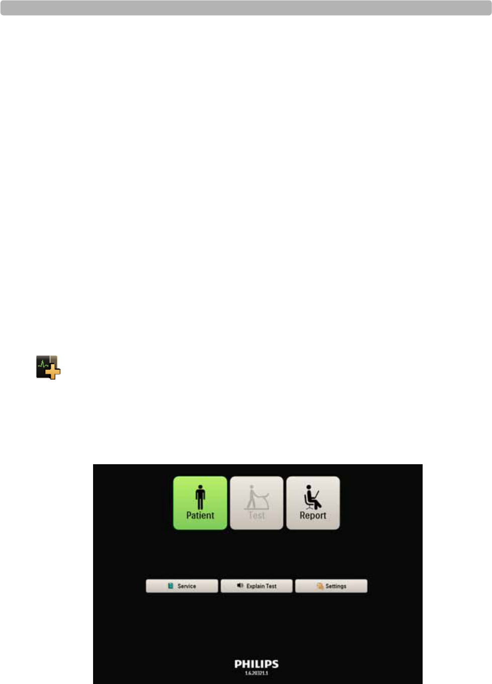
User Accounts
ST80i Stress Test System Instructions for Use 2-3
User Accounts
User accounts are created with specific access privileges based on function. ST80i user
accounts are categorized as follows:
Administrators – these users are allowed to perform all operations on the system.
Clinicians – these users are allowed to perform all operations on the system except most
configuration operations. The only configuration that the Clinician would be able to
perform is report configuration for fine tuning on final reporting (“Finalizing”).
Technicians – these users are allowed to perform all operations on the system except
configuration and “Finalizing.”
Only clinicians and administrators would be able to electronically sign the report.
ST80i supports at least 100 user accounts.
Starting the Application
Your user account is used to access the application. When you log into ST80i, you are logging
into your preconfigured user profile.
To log in
1Double-click the ST80i icon on your desktop. The ST80i window opens.
2Type your User Name and Password.
3Click OK.
The Main screen opens.
Figure 2-1 Main screen

An Overview of the ST80i Stress Test System
2-4 ST80i Stress Test System Instructions for Use
The Main screen is where you perform all tasks for the application.
To conduct a stress test, click Patient.
To enter the stress system database to review and retrieve archived reports, click Report.
In this area, you can also replay, delete, or export a selected exercise stress test.
To review, update, or test software and firmware configurations, click Service.
To hear an audio explanation of the exercise stress test, click Explain Test.
NOTE ST80i ships with a default audio file that explains the exercise stress test; however, you may record
your own audio file and configure ST80i to play this file when the user clicks the Explain Test button.
For more information, see the ST80i Installation and Configuration Guide.
To preconfigure or change system settings, user profiles, exercise protocols and user
accounts, click Settings.

User Accounts
ST80i Stress Test System Instructions for Use 2-5
User Profile
The system ships with a default user profile that cannot be deleted. The user profile contains
preconfigured settings that are used to determine how the test will run and how the test results
will be displayed, printed, saved, and exported. Some settings are fixed and cannot be
changed; some settings represent a default view, which can be changed during the exercise
stress test.
The preconfigured parameters of the user profile include:
Exercise protocol and equipment
Lead formats
Display settings
Report settings
Freeze display
Filter settings
Algorithm settings
Notifications
Audio prompts
See “Using the Toolbar Icons” on page 2-15 for an explanation of the settings that can be
changed during the patient session. See also “Side Panel” on page 2-11 for an explanation of
the display features that are continuously updated during the patient session. On this panel you
can manually override blood pressure and SpO2, as well as equipment settings that are
preconfigured as part of the user profile and/or protocol.
Refer to the ST80i Installation and Configuration Guide for an explanation of how user
profiles are pre-configured.
Before beginning with the exercise stress test, it's important to understand the key features of
the ST80i user interface along with the Toolbar icons, since you will be using them during the
patient session.
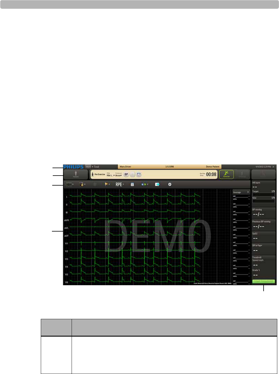
An Overview of the ST80i Stress Test System
2-6 ST80i Stress Test System Instructions for Use
ST80i Test Screen
The ST80i Test screen (user interface) provides:
All key procedural information including the protocol being used
Pop-ups, drill-down menus, and notes pages that can be viewed then hidden so that the
leads can be viewed in their entirety
Time of Day for correct time stamp on the start-up screen for every stress test
Real-time ECG as well as NIBP and SpO2, Trends, and other numeric displays that
include ST values, ST slope, Double Product, and ST/HR index
On the Test screen, you have command of several functions during a patient session. You can
adjust the speed and elevation of a treadmill and insert manual blood pressure data. You can
also abort the exam at any point without losing any patient data. However, note that the
exercise data will be lost.
Figure 2-2 ST80i Test screen
Table 2-1 ST80i Test Screen Features
Feature Description
ATitle Bar - displays patient name date of birth and ID, along with current date
and time; during the patient session, you can click the patient name in the Pre
Exercise phase or Report phase to update patient information; also where the
PIM battery status and RF transmitter LED indicators appear.
A
B
C
D
E
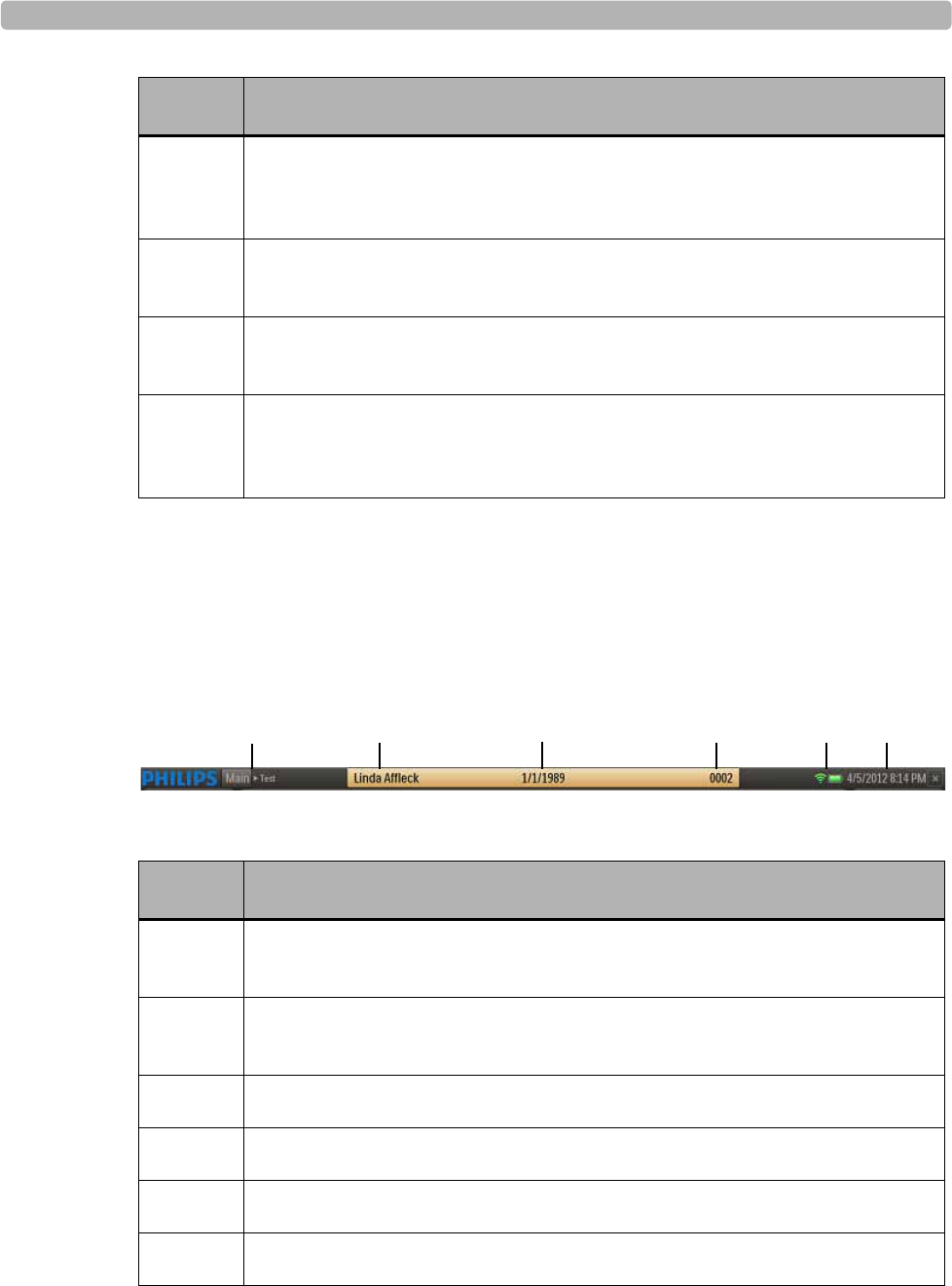
ST80i Test Screen
ST80i Stress Test System Instructions for Use 2-7
Title Bar
At any time during the Pre Exercise or Report phases of the patient session, you can use the
title bar to manually input and edit patient information with data that will be centrally stored in
the stress database. The Title Bar includes the features shown and described below.
Figure 2-3 TitleBar
Table 2-2 Title Bar Features
BProcedure Bar - used to control the exercise stress test process; shows exercise
stage; selected patient interface device; protocol; BP, ECG Print and Rhythm
Print buttons; and stage time
CToolbar - displays the Toolbar icons that provide quick access to frequently
used commands throughout the exercise stress test
DWaveform Screen - provides real-time ECG waveforms during the exercise
stress test
ESide Panel - provides real-time updates during the stress test as well as target
heart rate, NIBP and SpO2, and exercise equipment data (speed, grade, stop &
start)
Feature Description
ANavigation Keys [Main Test] - Click Main to leave exercise test and return to
Main screen
BPatient Name - Click the patient name to update patient information and add
notes on the Patient Information tab of the Patient Demographics screen
CPatient's Date of Birth
DPatient ID
ELED indicators for the RF Transmitter and PIM battery status
FCurrent Date and Time
Feature Description
AB C DEF
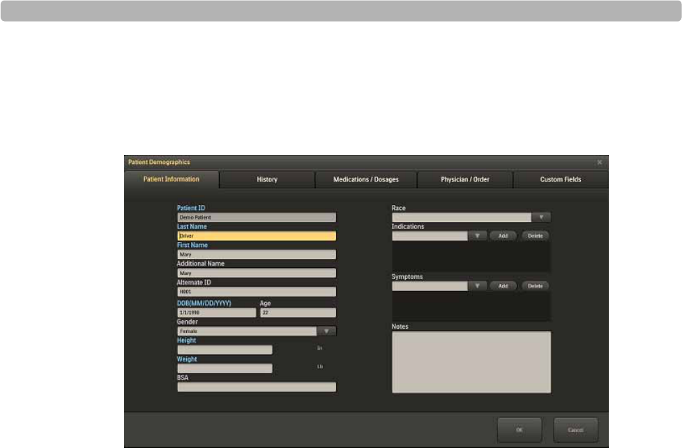
An Overview of the ST80i Stress Test System
2-8 ST80i Stress Test System Instructions for Use
To add or update patient information
1Click on the Patient Name in the title bar.
The system displays the Patient Demographics window.
Figure 2-4 Patient Demographics window
2Enter new information for the patient or update the fields as needed during the stress test.
3Click OK when finished to save the data.
If you manually update patient information, including Notes and Symptoms during the test or
on the Report screen, this information is not updated in the Patient profile in Worklist.
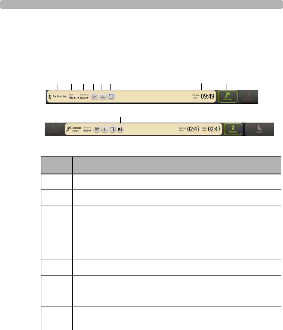
ST80i Test Screen
ST80i Stress Test System Instructions for Use 2-9
Procedure Bar
By default, the Procedure Bar is at the top of the screen. You can change the location of the
Procedure Bar to the bottom of the screen. See the ST80i Installation and Configuration Guide
to change the default setting [Settings User Profile Display].
Figure 2-5 Procedure Bar
Table 2-3 Procedure Bar Features
Feature Description
ACurrent exercise phase (Pre Exercise, Exercise, Recovery, Report)
BPIM device (only in the Pre Exercise stage)
CProtocol (Protocol drop-down list)
DBP button - used to manually command the optional automatic blood pressure
(NIBP) device to take an unscheduled blood pressure measurement
EPrint ECG button
FRhythm print button
GAdvance (to the next stage) or Stop buttons
HExercise stage and time
IPhase buttons (Pre Exercise, Exercise, Recovery, Report) - next phase is
illuminated in green
ABCDEF
G
HI

An Overview of the ST80i Stress Test System
2-10 ST80i Stress Test System Instructions for Use
Toolbar
The Toolbar contains the Toolbar icons that are used during the patient session. The icons
provide quick access to frequently used commands.
During the patient session, the waveform screen is displayed. You can use the Toolbar icons
during the patient session to view or hide specific exercise stress test data - which appear as an
overlay on the waveform screen.
Some of the icons allow you to change specific default settings as you proceed through each
phase of the patient session, while others give you a magnified view of various data in relation
to the ECG.
When you mouse over each icon, a Tool Tip is displayed.
See “Using the Toolbar Icons” on page 2-15 for a complete description of the icons and their
functionality.
The default setting for the Toolbar is at the top of the screen. You can change the location of
the Toolbar to the bottom of the screen. See the ST80i Installation and Configuration Guide to
change the default setting [Settings User Profile Display].
Waveform Screen
Real-time ECG waveforms appear on the Waveform screen. The default setting is 12-Lead.
With the customizable options of ST80i, you can use the Toolbar icons do the following:
Change the default lead you want to view (12, 6x2, 6, 3)
Display the magnified beat
Display and/or print the average complexes
Show or remove magnified beat, trends, anatomical representations and average
complexes from the ECG print strip
On the bottom of the screen, the current settings appear for the following:
Limb Lead amplitude
Chest Lead amplitude
Speed of trace display
Filter – low and high pass
Figure 2-6 Limb Lead, Chest Lead, Speed, and Filter Settings
When you change these default settings using the Toolbar icons, they appear in this location.
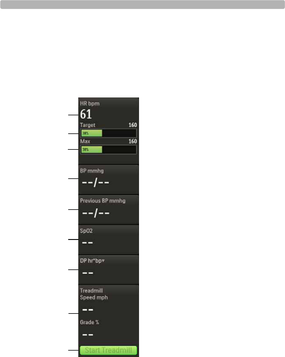
Side Panel
ST80i Stress Test System Instructions for Use 2-11
Side Panel
The Side Panel shows a continuous display of all relevant physiological parameters as well as
visual indicators for current heart rate and a dynamic change in heart rate. From the Side
Panel, you can override NIBP and SpO2 values. In addition, you can change the treadmill
speed and duration during a patient session or stop the treadmill altogether.
The Side Panel provides the following:
Figure 2-7 Side Panel
A
B
C
D
E
F
G
H
I
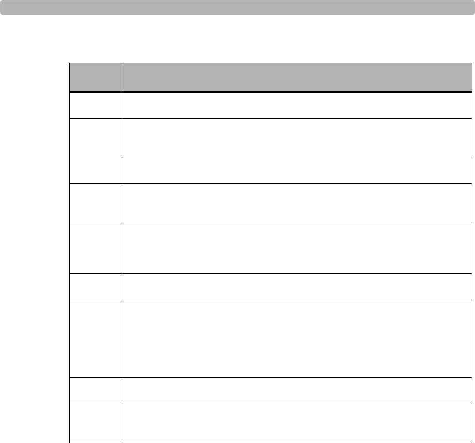
An Overview of the ST80i Stress Test System
2-12 ST80i Stress Test System Instructions for Use
Table 2-4 Side Panel Features
Heart Rate bpm
This field shows the current heart rate of the patient.
Target Heart Rate (130)
There are visual and audible indicators when the target heart rate is achieved.
This field shows the % of Target Heart Rate achieved.
Target Heart Rate is X% of maximum heart rate – as established in User Profile
Target Heart Rate % is pre-set (typically 85%)
See the information regarding Target Heart Rate in the ST80i Installation and Configuration
Guide.
Feature Description
AHeart rate beats per minute
BTarget heart rate – visual and audible indicators when target heart rage is
achieved
CMaximum heart rate
DBP mmhg – current blood pressure; used also to manually insert current BP
measurement
EPrevious BP mmhg – when BP is taken as pre-configured by stage, previous
BP is shown; previous BP is also shown when you manually insert current BP
measurement
FSpO2 numeric data with appropriate stage; you can manually insert SpO2 data
GDP hr*bp (Double-Product – default); drop-down includes:
METS – establishes metabolic equivalent [Algorithm calculation of HR,
speed of Treadmill, etc.]
ST mm – ST Index
HTreadmill speed (mph), grade %, or ergometer watts
ITreadmill or Ergometer button (Start/Stop). The button displays “Unavailable”
when the treadmill or ergometer is unavailable.

Side Panel
ST80i Stress Test System Instructions for Use 2-13
Max (220)
Shows the maximum heart rate for patient, male or female.
BP mmhg
When the patient's NIBP is collected during the exercise stress test based on the defined
interval in the Exercise Protocol (Off, Begin, End, Every), the BP mmgh field displays the
measurement. If you click the BP button during the patient session, the current blood pressure
measurement also displays in this field.
With this interface, there are visual and audio prompts (if enabled) for NIBP acquisition.
To enable audio alerts, see the ST80i Installation and Configuration Guide.
This field is also used to manually enter a blood pressure measurement, if an NIBP monitor is
not being used.
To override NIBP or manually insert the blood pressure measurement
NOTE Once the NIBP or BP is manually overwritten, ST80i no longer updates the real-time value from the
NIBP monitor.
1Click the dashed lines or current BP value in the BP mmhg field.
2Type in the blood pressure measurement.
3Click OK.
Previous BP mmhg
When the blood pressure monitor records the current blood pressure measurement, the
Previous BP mmgh field displays the previous measurement. It will also display the previous
blood pressure measurement when you click the BP button on the Procedure bar.
If you are using a blood pressure cuff, when you manually enter the blood pressure
measurement, this field records the previous blood pressure measurement.
SpO2
The patient’s SpO2 is collected in real time through a sensor. During the stress test, SpO2 is
measured automatically and is continuously displayed on the screen. With this interface, there
are also visual and audio prompts (if enabled) for SpO2 acquisition.
To enable audio alerts, see the ST80i Installation and Configuration Guide.
You can override the NIBP and SpO2 values. Depending on the NIBP monitor used, you may
need to manually enter the SpO2 data.

An Overview of the ST80i Stress Test System
2-14 ST80i Stress Test System Instructions for Use
To override or manually enter the Sp02
1Click the dashed lines or value.
2Type in the latest SpO2
3Click OK.
Double Product (HR*BP)
Double Product is the current heart rate times the current blood pressure measurement.
Use the drop-down arrow to change from Double Product display to the following:
About METS
About ST X mm (or mV) – X is the selected Zoom Lead
About METS
The METS calculation establishes a metabolic equivalent based on the Algorithm calculation
of HR, speed of treadmill, etc.
About ST X mm – by Zoom Lead
You have the option to change the lead in view using the drop-down menu to view the ST
Index (ST level).
To change the lead in view
1Click the Hide/Show View icon.
2Select Show Zoom ST.
3Click the Lead drop-down arrow in the Zoom ST lead display.
4Select the lead to view.
Treadmill Speed, Grade %
These two fields capture the treadmill speed and elevation by stage.
You can also use these fields to manually change the treadmill speed and elevation. To do
this, see “Controlling the Treadmill or Ergometer” on page 3-35.
During the entire stress test, the host-side application validates the response between the
treadmill (or ergometer) and the PC to ensure that the communication is successful.
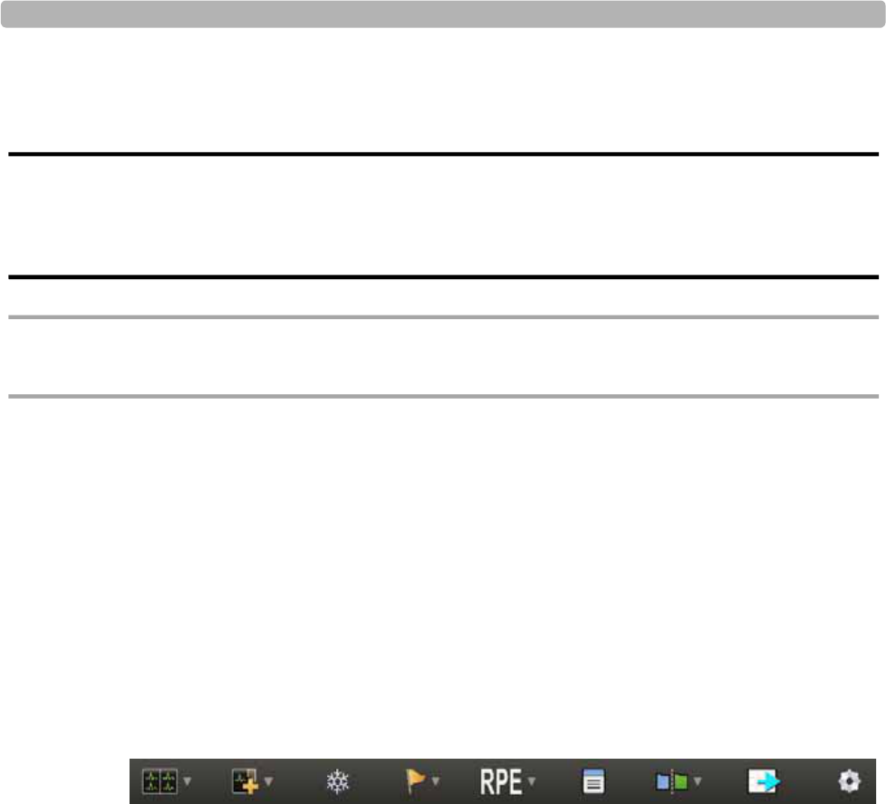
Using the Toolbar Icons
ST80i Stress Test System Instructions for Use 2-15
Treadmill Button
The Treadmill button is used to stop and start the treadmill during a patient session.
WARNING The ST80i USB and RS-232 ports should be connected only to treadmills, ergometers, and NIBP
monitors that are certified to meet IEC 60601-1 and are listed as supported devices in the Instructions
for Use. See “Supported Treadmills and Ergometers” on page E-7 of Appendix E, “Specifications and
Requirements”.
CAUTION If the “Stop Treadmill” GUI button does not respond for any reason, immediately press the red
“Emergency” button on the treadmill handrail.
Ergometer Button
The Ergometer button is used to stop and start the ergometer during a patient session.
Using the Toolbar Icons
Generally, you will not change the settings associated with a selected profile and protocol
during an exercise stress test. However, there may be instances when you wish to change
specific display settings. You can change display settings by using the Toolbar icons.
Figure 2-8 Toolbar Icons
When you mouse over each icon, a Tool Tip is displayed.
Using the Toolbar icons, you can do the following:
Select what leads to view in real time
Change the default setting of the waveforms on the waveform screen
Display a zoomed view of an average complex to either a specified lead or for the lead that
shows the most significant change in ST level
Freeze the ECG or enable a filter to reduce noise
Use the lead map diagram to check the lead wire contact with a predefined, color-coded
indicator to show which lead is off
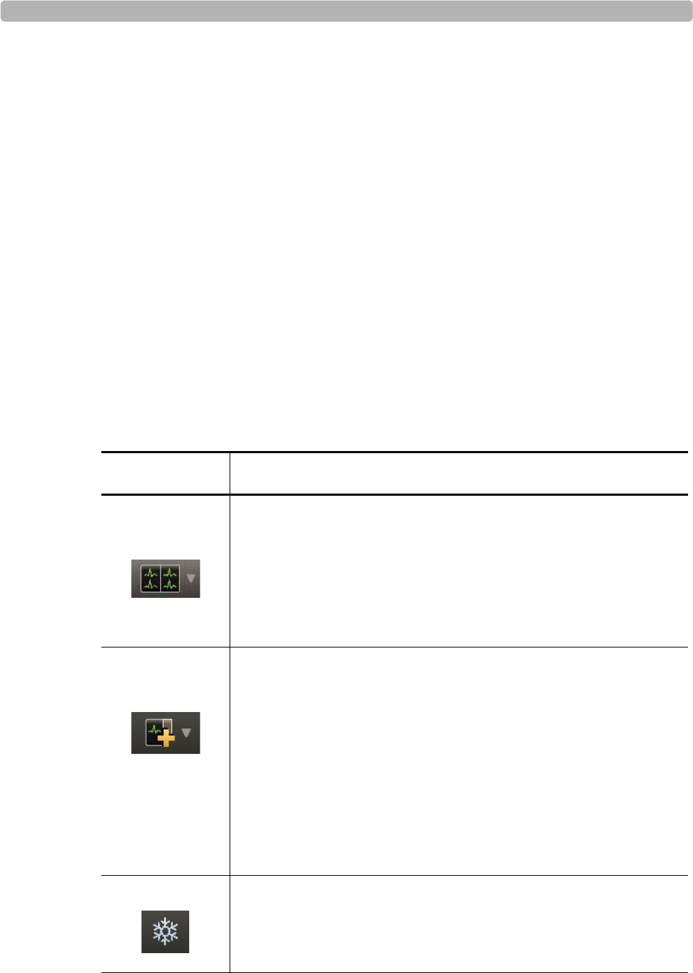
An Overview of the ST80i Stress Test System
2-16 ST80i Stress Test System Instructions for Use
Compare the current averages with reference ECG (resting, supine, hyperventilation
averages) and worst case for all 12 leads. ST80i is able to select a new ECG complex or
10s strip as the new reference. This can be done on the screen and is available at any point
during the test.
Hide or show the magnified beat, trends, anatomical representations (ST Map) and
average complexes that appear over the real-time waveform display
View a two-dimensional, color-coded anatomical representation of ischemic area/
segments (ST Map); 2D real-time updates anatomical representation (ST Map) every 10
seconds
Create events during the test with associated notes
View trend graphs for Heart Rate, METS, BP, SpO2, and ST values at any time
View magnified ST and morphological changes (including ST morphology changes, T
wave morphology changes, QRS morphology changes) in the various leads.
The following table provides an overview of each icon.
Table 2-5 Toolbar Icons
Icon Description
Waveform The default is 12 leads; you can select from the following:
12 Leads
6x2 Leads
6 Leads
3 Leads
Hide/Show View Select from the following:
Show Lead Map
Show Zoom Lead
Show ST Map
Show Trend View [HR/METS; BP; ST Level]
Show Average
Note that these settings are “sticky” – once selected they will remain
until deselected.
Freeze Freezes the ECG in a moment in time so that you can print the event

Using the Toolbar Icons
ST80i Stress Test System Instructions for Use 2-17
Event Select the Event from the drop-down list and do X. The Events include:
Supine
Stand
Mason-Likar
Hyperventilation
Chest Pain
Shortness of Breath
Add New Event
RPE
Rate of Perceived Exertion; from preconfigured setting
Note
Insert comments about patient and/or test
Compare
Compare the current zoomed ECG with a previous moment in time to
compare [the delta]
Page
Form-feed adjustment for thermal paper
RELEARN
Table 2-5 Toolbar Icons
Icon Description
An Overview of the ST80i Stress Test System
2-18 ST80i Stress Test System Instructions for Use
Waveform
Real-time ECG analysis employs the latest C-Alg analysis to calculate an adult patient's ECG
for ST segment (elevation or depression) and to produce events and notifications
simultaneously for all supported ECG leads.
The real-time waveform default is the 12-Lead. You can choose from four display formats for
the real-time ECG:
12 Leads
6 x 2 Leads
6 Leads
3 Leads
To change the real-time ECG format
1Click the Waveform icon.
2Select which lead configuration you want to display from the drop-down menu:
– 12 Leads
– 6 x 2 Leads
–6 Leads
–3 Leads
The Waveform screen display changes to the new setting.
Hide/Show View
To allow maximum viewing of the waveforms, some views are hidden. Use the Hide/Show
View icon to display the following:
Gear Quick Settings:
Filter (LP, HP, AC, Artifact, Smart)
Display (Limb Gain, Chest Gain, Speed)
Rhythm Print (Leads, Limb Gain, Chest Gain, Speed)
Sync Out (Analog Out 1 – Amplify Ratio; Analog Out 2 – Amplify
Ratio; TTL Out – Polarity, Duration)
Table 2-5 Toolbar Icons
Icon Description
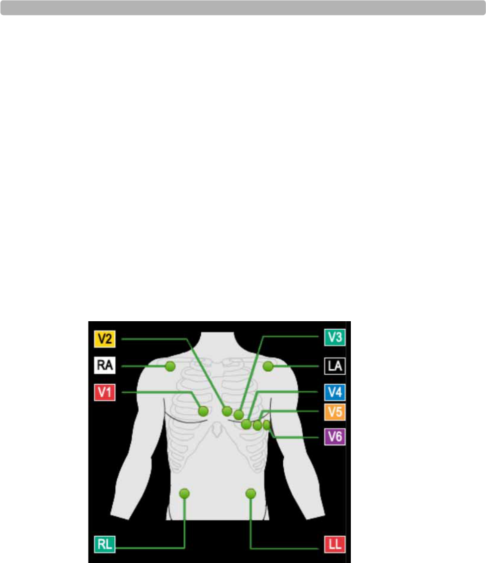
Using the Toolbar Icons
ST80i Stress Test System Instructions for Use 2-19
Show Lead Map
Show Zoom ST
Show ST Map
Show Trend View (HR/METS; BP; ST Level)
Show Average
About the Lead Map
The Lead Map diagram shows the status of each lead. Yellow indicates lead-off, and green
indicates good contact.
To view the Lead Map
1Click the Hide/Show View icon.
2Select Show Lead Map.
The Lead Map appears in the top-right corner of the waveform.
All connections need to be green.
Figure 2-9 Lead Map Display
If a lead is off, a red “X” is displayed on the lead map and red, dashed flat line is displayed
in the real-time ECG view. On the PIM, this condition is verified by a yellow LED light.
3To close the Lead Map, click the X in the upper-right corner.
NOTE When a leads-off condition is detected, the leads-off indicator string will be printed as a dashed line on
the report and the indicator will be saved when saving the report.

An Overview of the ST80i Stress Test System
2-20 ST80i Stress Test System Instructions for Use
About the Zoom ST
The Zoom ST lead display shows one expanded average ECG complex, which is an averaged
ECG enlarged to four times the normal size.
The absolute ST segment values and slope values are displayed for the expanded lead. This
function allows you to better visualize the ST segment changes during the test.
The default ST lead is shown in the zoomed QRS window during the exercise stress test.
When you begin a test, the default ST lead that is shown in the zoomed display is
preconfigured in the user profile. You can select any lead as the zoomed lead from the
Lead drop-down arrow.
You can also select a lead for the default setting. For default settings, see the ST80i
Installation and Configuration Guide.
NOTE Whichever lead is selected as the Zoom ST lead, the ST change trend for this lead is also displayed in
the Trend display. See “About Trend View” on page 2-22.
On the Zoom ST display, the following are displayed:
ST Level (mm or mV)
ST Slope (mV/s or mm/s)
J-Point – default is 60 mm
Default Lead – drop-down
Reference – drop-down
NOTES ST80i can display the lead with the maximum absolute value of the ST level if you select “Max ST
Level” using the drop-down arrow by the default lead.
When using the Compare icon, the averaged ECG is superimposed on the blue reference ECG so that
you can compare current and reference data.
The viewing options for zoomed lead are:
Table 2-6 Zoom Lead Options
Zoom Lead Option Description
Any individual lead - Any of the
twelve leads. This selection remains in force until you change it.
Dynamic The system monitors all twelve leads and displays the
one with the most significant ST change. The lead that
appears will change automatically during the stress
test; the changes are reflected on printed reports, as
well.
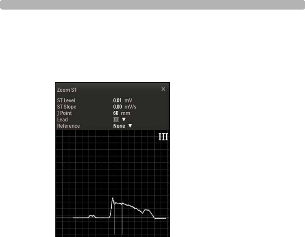
Using the Toolbar Icons
ST80i Stress Test System Instructions for Use 2-21
To view the Zoomed ST Lead
1Click the Hide/Show View icon.
2Select Show Zoom ST.
The default Zoom lead appears as one expanded average ECG complex on the waveform.
Figure 2-10 Zoom ST Display
3To close, click the X in the upper-right corner.
To change the Zoomed ST Lead
1Click the Hide/Show View icon.
2Select Show Zoom ST
The default Zoom Lead name appears on the waveform.
3Use the Lead drop-down menu to change to another Zoom Lead.
4To close, click the X in the upper-right corner.
About the ST Map
The two-dimensional, color-coded ST map, which can help to identify ischemic areas in the
myocardium, is based on both the ST deviation and ST slope. It updates every 10 seconds and
can be displayed on the waveform screen.
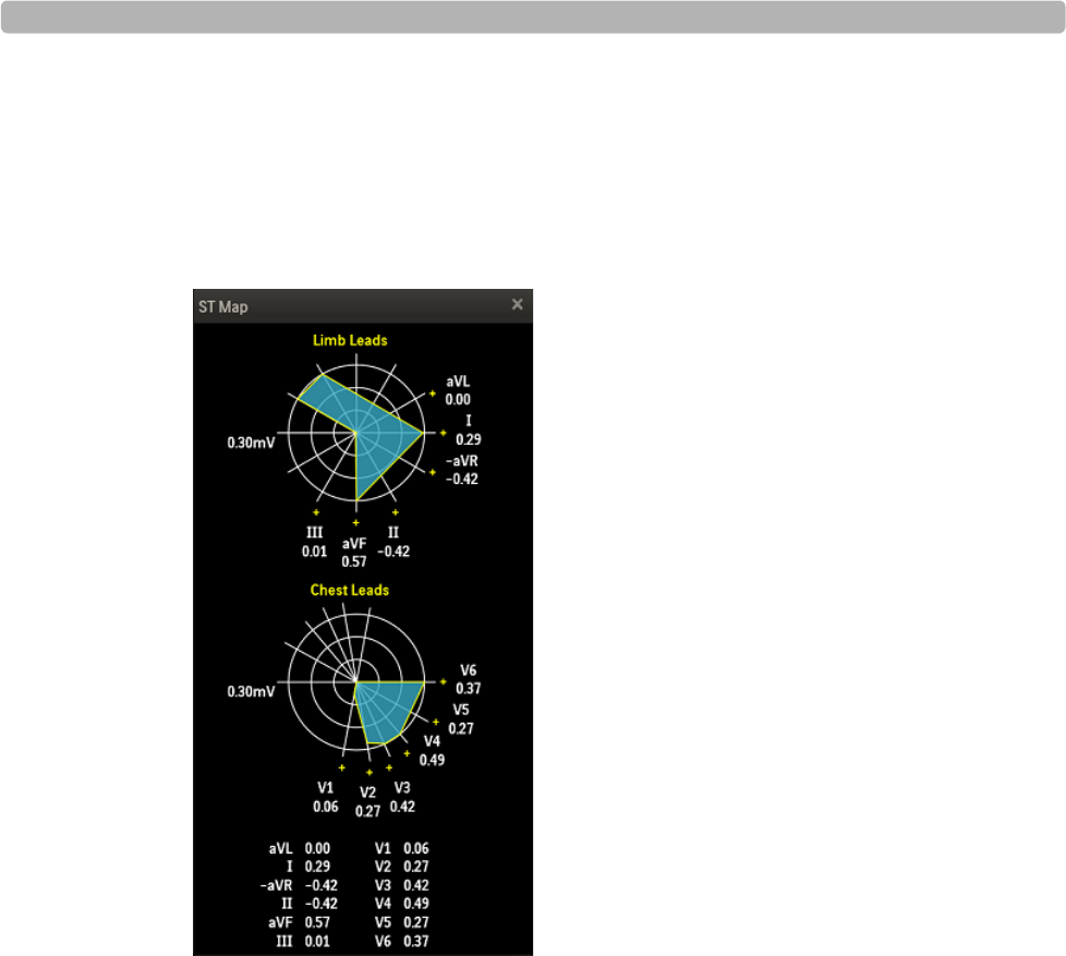
An Overview of the ST80i Stress Test System
2-22 ST80i Stress Test System Instructions for Use
To view the ST Map
1Click the Hide/Show View icon.
2Select Show ST Map.
The ST Map displays on the waveform.
Figure 2-11 ST Map
3Click the X in the upper-right corner to close the ST Map.
About Trend View
The Trends graphs show a visual indicator for the current heart rate as well as the dynamic
change in heart rate. The Trends data appears in 3 charts that can be viewed at any time.
NOTE Whichever lead is selected as the Zoom ST lead, the ST change trend for this lead is also displayed in
the Trend display.
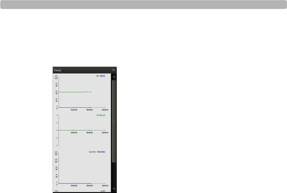
Using the Toolbar Icons
ST80i Stress Test System Instructions for Use 2-23
To view Trends
1Click the Hide/Show View icon.
2Select Show Trend View from the drop-down menu.
Figure 2-1 Show Trend View
The Trends View has three charts:
– HR/METS
– ST J + mV
– BP (Systolic, Diastolic)
3Click the X to close the Show Trends view.
About HR/METS
This two-dimensional, color-coded chart is a visual indicator for both the current heart rate
and a dynamic change in heart rate. The chart’s X-axis represents time, and the HR value is
shown as a curve, representing the dynamic change over time. The Trend graphs of heart rate
can be viewed at any time.
METS refers to the estimated metabolic equivalents.
About ST J+ mV
The J-ST time interval is preconfigured in the user profile. This setting specifies the number of
milliseconds after the J-point that the ST value is measured. You cannot modify the J-ST time
interval during a patient session; it must be done in advance. To modify the J-ST time interval
in advance, see the ST80i Installation and Configuration Guide. You can, however, change the
J-point on the Report screen. See “Change (J+) Point” on page 4-7 for more information.
The ST-Amplitude calculation is absolute and is shown in mm.
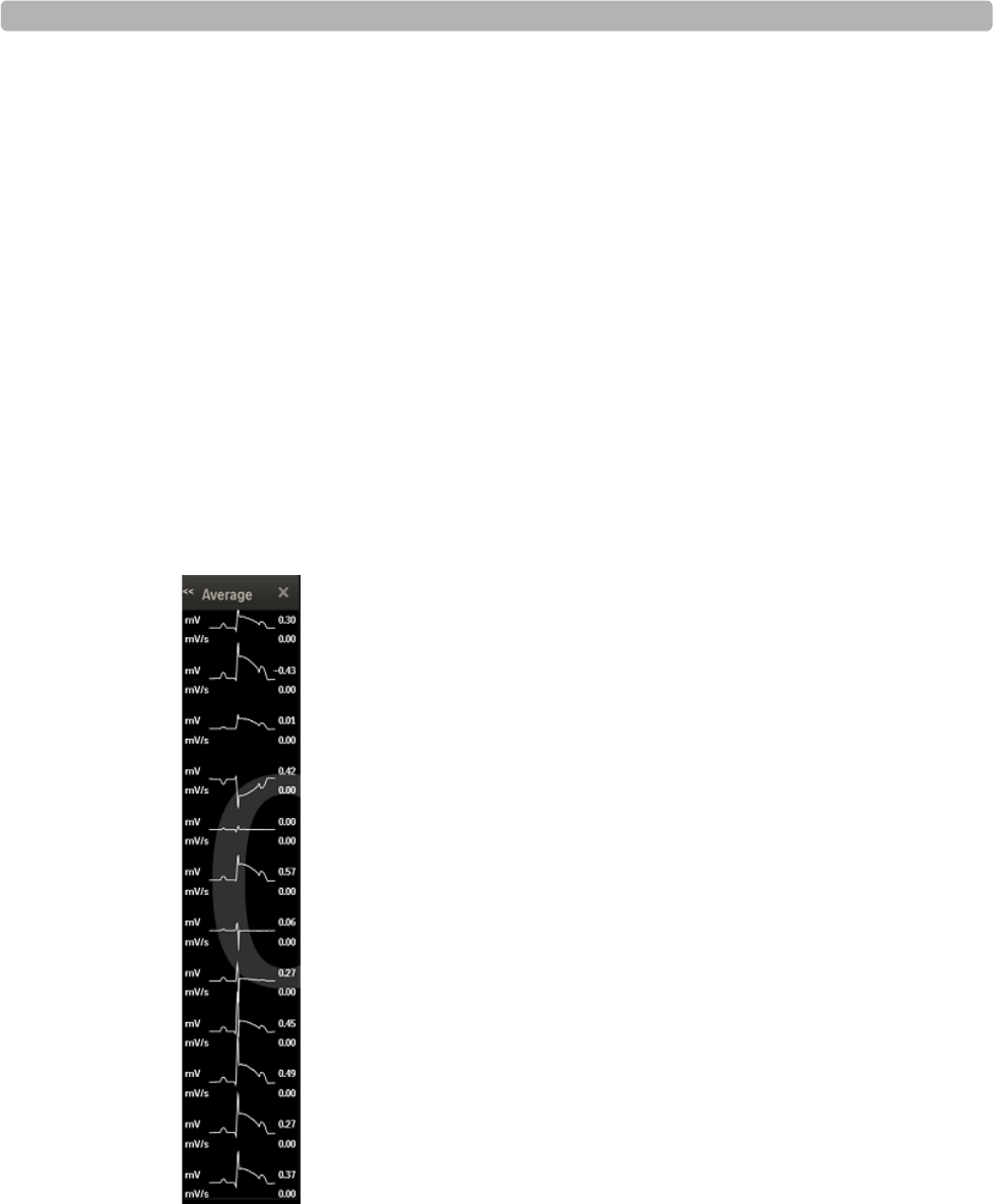
An Overview of the ST80i Stress Test System
2-24 ST80i Stress Test System Instructions for Use
About BP
About the Average Complex Display
The Average Complex display shows one average complex for each of the 12 leads regardless
of what lead format is being displayed.
The system displays the ST value in microvolts (or mm) for the on-screen average complexes.
To change the ST value from mV to mm, see the ST80i Installation and Configuration Guide.
To view the Average Complex Display
1Click the Hide/Show View icon.
2Put a checkmark in the Show Average box.
The Average displays along the right-hand side of the waveform screen.
Figure 2-2 Average mV and mV/s for each Lead
3Click X to close the display.
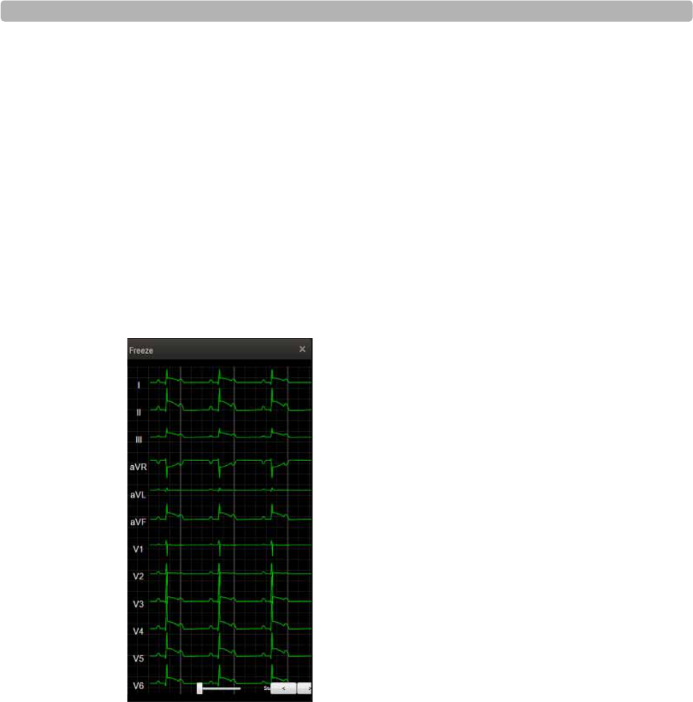
Using the Toolbar Icons
ST80i Stress Test System Instructions for Use 2-25
Freeze
You can print a 12-Lead ECG at any time by clicking the Print button. During the Exercise
phase, when you select the Freeze icon, it freezes the most recent 10 seconds of ECG data so
that you can view a specific event. A dialog box displays a Freeze image of all leads captured
at the moment you clicked the Freeze icon.
A scroll bar at the base of the Freeze image allows you to scroll to view any part of the frozen
ECG.
To freeze the ECG
1Select the Freeze icon.
The Freeze display appears on the right-hand side of the waveform screen.
Figure 2-3 Freeze Display
2Use the slide bar or right/left arrows to scroll through the ECG.
3Click X to close the display.
Recording an Event
Events are associated with the user profile. You can add and delete events when you create a
user profile. As the test progresses, you can record events, if and when they occur. You can
also add events to the drop-down list that appears by clicking the down arrow by the icon in
the Toolbar.
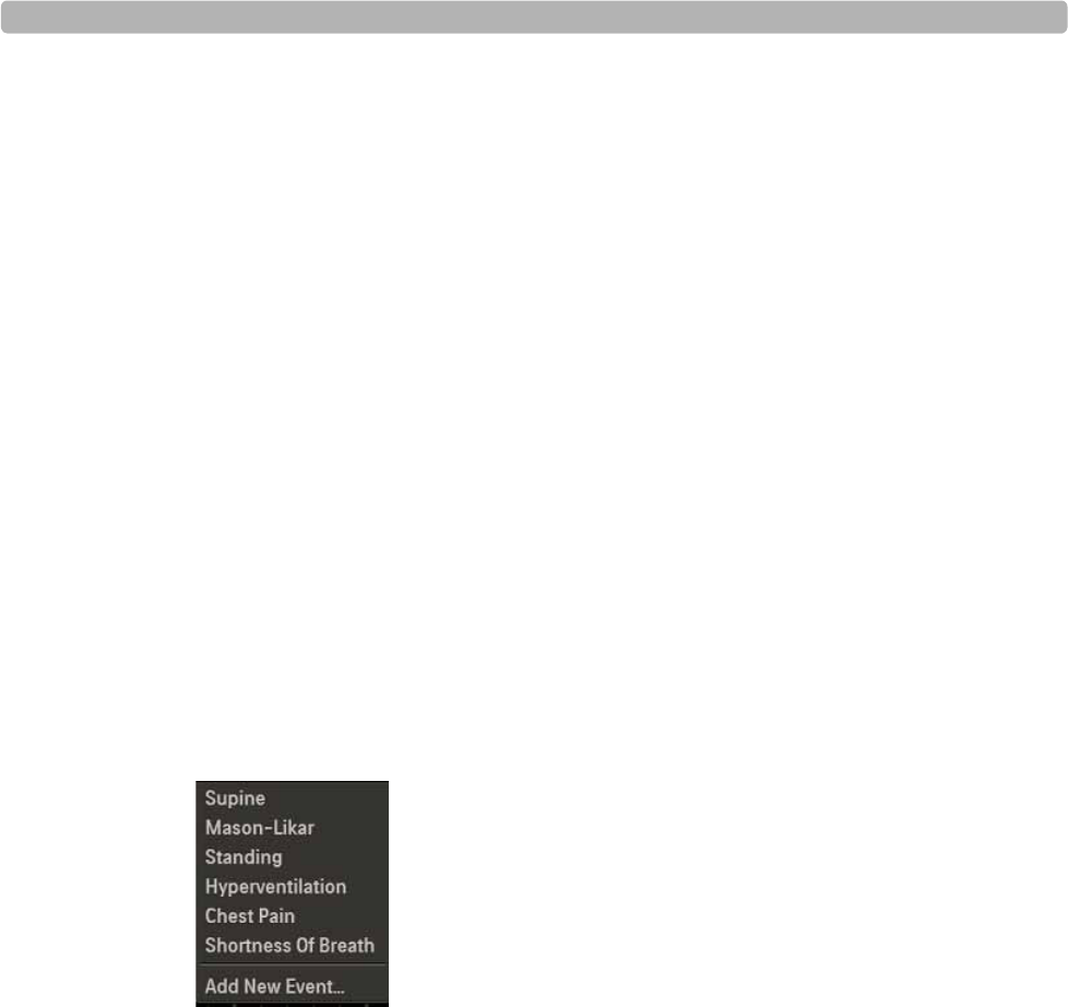
An Overview of the ST80i Stress Test System
2-26 ST80i Stress Test System Instructions for Use
When you record an event, ST80i generates a 12-lead ECG and documents the event name on
the ECG. The system also stores the event in memory and will print it in the Rhythm Events
portion of the final report. User Notes are also associated with the Event, if created. See
“Note” on page 2-28 regarding the Note icon.
In addition, ST80i automatically detects an arrhythmia event–if this is enabled. To enable
Arrhythmias, see the ST80i Installation and Configuration Guide. See also “Notifications and
Alerts” on page 3-36.
The default events include:
Supine
Mason-Likar
Standing
Hyperventilation
Chest Pain
Short of breath
To record an event
1Click the Event button to display the Event drop-down list’
Figure 2-4 Event Drop-Down List
2Select the event to record from the drop-down list.
The system prints an ECG and records the event for the final report.
To add an event
1Click the Event button
2Click Add New Event from the drop-down list to display the Add New Event pop-up box.
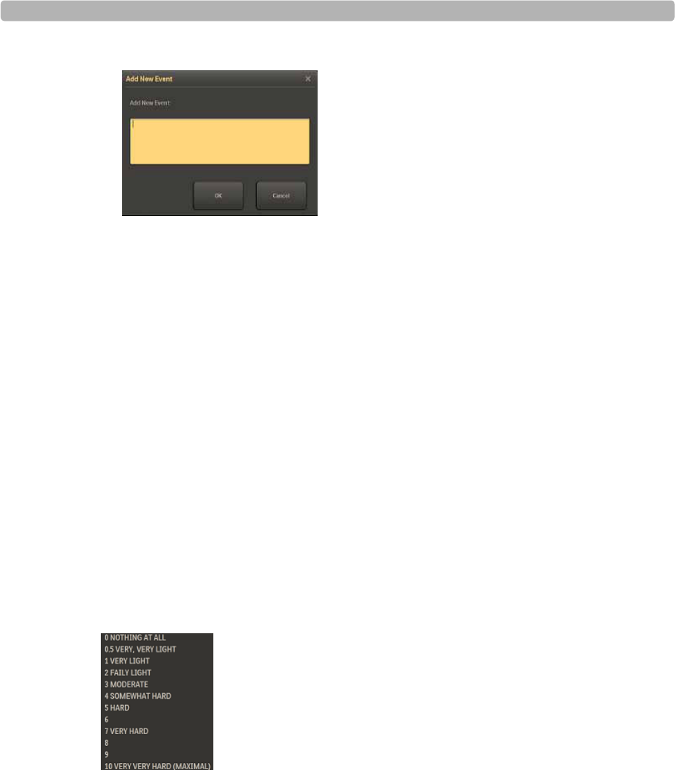
Using the Toolbar Icons
ST80i Stress Test System Instructions for Use 2-27
Figure 2-5 Add New Event Window
3Type in a name for the new event.
4Click OK.
The system prints an ECG with the new event label and records the new event for the final
report.
Recording RPE
The Rate of Perceived Exertion (RPE) scale provides an indication of the percentage of
maximum work being done by a patient. The RPE scale subjectively rates work (physical
exertion) as stated by the exercising patient. It provides a means to quantify a patient's level of
exertion.
RPE scales can be expressed in two ways, 1 to 10 or 6 to 20. The scale used is associated with
the selected user profile. To set the RPE scale, see the ST80i Installation and Configuration
Guide.
When you want to record an RPE score, ask the patient to state which number or statement
represents their perceived level of work. Then select the corresponding number from the drop-
down list. Once the number is selected, the system prints an ECG report, noting the RPE.
Figure 2-6 RPE Drop-down List
To record the patient's RPE
1Display the RPE drop-down list by clicking the RPE down arrow.
2Select the RPE statement that matches what the patient reports, and click OK.
The system prints an ECG with the RPE statement.
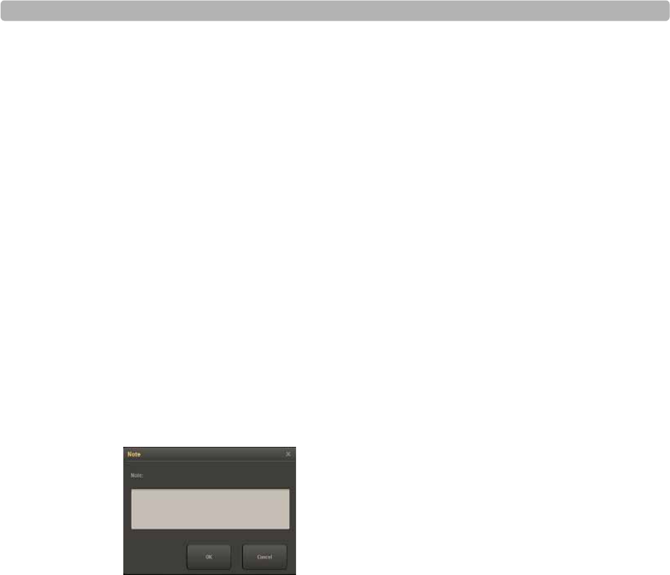
An Overview of the ST80i Stress Test System
2-28 ST80i Stress Test System Instructions for Use
3Continue this process throughout the Exercise phase.
The RPE ECG is also held in memory, and is printed in the Rhythm Events section of the final
report.
For an explanation of how this appears in the final report, see “Working with Reports” on
page 4-1.
Note
During the patient session, you can add notes about the patient's progress as well as important
information regarding the exercise stress test. These comments will be stored in the Notes
section of Patient Demographics database and they will also appear as part of the Final Stress
Report.
For an explanation of how the notes appear in the final report, see “Working with Reports” on
page 4-1.
To add a Note
1Select the Note icon to display a pop-up box in which you can add notes.
Figure 2-7 Note Window
2Click OK to save the note.
Compare
ST80i is able to compare the current averages with reference ECG (resting, supine,
hyperventilation averages) and worst case for all 12 leads.
As the heart rate increases and/or morphological changes occur, the Compare function is used
to view the QRS morphology between a reference zoomed lead and a current event such as
Chest Pain or Hyperventilation to compare the delta between the two.
When the zoomed lead is displayed, the averaged ECG is superimposed on the reference ECG.
The white line represents current data; the reference data is blue.
To use the Compare icon
1Select the Hide/Show View icon.
2Select Show Zoom ST to display the zoomed QRS window. Change the default Zoomed
lead, if applicable.

Using the Toolbar Icons
ST80i Stress Test System Instructions for Use 2-29
3If you do not currently have a particular compare point, click the Event icon to select an
event or create a new event. An ECG will print.
4Select the Compare icon to compare the current state to when the event occurred or to an
earlier point in time.
A drop-down list of current events/compare points allows you to compare the current state
to when the event occurred or to an earlier point in time.
Figure 2-8 Compare Drop-Down List
5Select an item from the list.
The current zoomed ECG appears in white; the earlier or baseline zoomed ECG appears in
blue so that you can compare the ST elevation/depression of the two images.
Figure 2-9 Compared ECGs
6Click the X to close the image.
Page
Use the Page icon to advance the thermal paper, so that the printing starts at the top of the
page (at the perforation). This form-feed function for the thermal printer returns the paper to
“top of form.” You can also use the Page icon to advance the paper if there is a paper jam or
after installing a new package of paper.
Relearn
--add information about this button here--
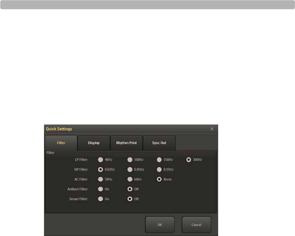
An Overview of the ST80i Stress Test System
2-30 ST80i Stress Test System Instructions for Use
Gear (Quick Settings)
Click the Gear/Quick Settings icon to display the four-tabbed Quick Settings window from
which you can change specific default settings that relate to the following:
Filter
Display
Rhythm Print
Sync Out
Figure 2-10 Quick Settings Window
Filter
The Filters are pre-configured in the Settings section of the application. When you log into
ST80i, the active settings of the filters are set to a stored default set that are associated with
your user profile.
The ECG data is stored in its unfiltered state (0.02 - 300Hz, all filters off) and user-selected
settings are stored with the ECG."
NOTES The ECG data is filtered at 0.05-150Hz before being analyzed by the algorithm. This filter is called the
algorithm filter and cannot be turned off by user. The algorithm filter is independent from other filters
and is neither controlled by the user nor affects the saved ECG data.
All filters can be turned on or off as needed to improve signal quality except for the algorithm filter (as
described above) and minimum filters (0.02Hz high pass filter and 300Hz low pass filter).
Using the Filter tab in Quick Settings, you can change the default settings.
The options include:
Low Pass (LP) Filter: 40Hz, 100Hz, 150Hz, 300Hz
High Pass (HP) Filter: 0.02Hz, 0.05Hz, 0.15Hz

Using the Toolbar Icons
ST80i Stress Test System Instructions for Use 2-31
AC Filter: 50Hz, 60Hz, None
Artifact Filter: On, Off
Smart Filter: On, Off
The same filter settings apply to both displayed and printed waveforms. The filter settings are
printed with the report.
To change the Filter settings
1Select the Gear (Quick Settings) icon.
2Select the Filter tab.
3Change or modify each filter, as required.
4Click OK to save changes.
For more information, see “Filtering” on page 3-25.
Display
On the Display tab, you can change the Limb Gain, Chest Gain, and Speed.
To change the Display settings
1Click the Gear (Quick Settings) icon.
2Select the Display tab.
3Use the drop-down arrow to adjust the Limb Gain setting.
4Change the Chest Gain setting:
–Full
–Half
5Change the speed:
–25 mm/s
–50 mm/s
6Click OK to save your settings.

An Overview of the ST80i Stress Test System
2-32 ST80i Stress Test System Instructions for Use
Rhythm Print
Before you select the Rhythm Print icon from the Procedure bar to print a continuous strip,
you can modify your settings based on the following:
Leads
Limb Gain
Chest Gain
Speed
To change the Rhythm Print settings
1Click the Gear (Quick Settings) icon.
2Select the Rhythm Print tab.
3Place a checkmark for each lead you want to print. (1 - 13 leads are available.)
4Use the drop-down arrow to adjust the Limb Gain setting. (2.5, 5, 10, 20 mm/mv)
5Change the Chest Gain setting:
–Full
–Half
6Use the drop-down arrow to adjust the Speed. (5, 10, 25, 50 mm/sec)
7Click OK to save your settings.
Sync Out
ST80i supports two analog ECG output signals and one TTL ECG Sync Output on the
Advanced Interface Module (AIM).
Analog ECG Output - for synchronization with ECHO device for Stress-Echo procedures.
This signal is not to be considered as diagnostic quality.
TTL Sync Output - for QRS gating required by the Tango SunTech implementation of
NIBP measurement
CAUTION Sync ECG output signals are not real-time; therefore, they are not diagnostic quality and should not be
used for analysis.
They are pre-configured as part of the user profile. However, they can be changed during the
patient session.
See the ST80i Installation and Configuration Guide for how to configure Sync Out settings in
the user profile.

Using the Toolbar Icons
ST80i Stress Test System Instructions for Use 2-33
To change Sync Out settings
1Select the Gear (Quick Settings) icon.
2Select the Sync Out tab.
3Use the drop-down menu to modify the following:
– Analog Out 1 Amplify Ratio [drop-down]
– [Example: Analog Out: I; Amplify Ratio: 3 mV/V]
– Options: None; Leads I - V6
– Analog Out 2 Amplify Ratio [drop-down]
– [Example: Analog Out 2: None; Amplify Ratio: 1 mV/V
– Options: None; Leads I - V6
– TTL Out Polarity/Duration (ms) [drop-down]
– [Example: TTL Out: None; Polarity: Positive; Duration: 50 ms]
– Options: None; Leads I - V6
– Polarity (Positive/Negative)
– Duration: default is 100 ms.
4Click OK.

An Overview of the ST80i Stress Test System
2-34 ST80i Stress Test System Instructions for Use

3
3-1
1The Patient Session
Overview
A patient session is the period of time when the exercise stress test is performed, and
waveforms are acquired and processed for a single patient. Patient information is linked with
all waveform data acquired during the patient session. The session starts when you begin a
new exam and gather pre-exercise data, and lasts through generation of the final report.
In ST80i, the exercise stress test begins with the Pre Exercise phase and ends with the Report
phase.
Pre Exercise
Exercise
Recovery (and Post-Recovery)
Report
CAUTION Do not run any other applications, including screen savers, when performing an exercise stress test.
Once the test has begun, the ST80i application does not allow you to access other system functions.
This chapter provides the following information:
Overview . . . . . . . . . . . . . . . . . . . . . . . . . . . . . . . . . . . . . . . . . . . . . . . . . . . . . .3-1
Using the Patient Worklist. . . . . . . . . . . . . . . . . . . . . . . . . . . . . . . . . . . . . . . . .3-4
Worklist Tab . . . . . . . . . . . . . . . . . . . . . . . . . . . . . . . . . . . . . . . . . . . . . . . .3-5
Patient Information Management. . . . . . . . . . . . . . . . . . . . . . . . . . . . .3-5
Patient Information Fields . . . . . . . . . . . . . . . . . . . . . . . . . . . . . . . . . .3-6
Add a New Patient to the Worklist. . . . . . . . . . . . . . . . . . . . . . . . . . . .3-6
Find a Patient . . . . . . . . . . . . . . . . . . . . . . . . . . . . . . . . . . . . . . . . . . . .3-7
Edit Patient Information. . . . . . . . . . . . . . . . . . . . . . . . . . . . . . . . . . . .3-7
Delete a Patient Name . . . . . . . . . . . . . . . . . . . . . . . . . . . . . . . . . . . . .3-8
Download Preregistered Patient Information. . . . . . . . . . . . . . . . . . . .3-9
Review a Previous ECG. . . . . . . . . . . . . . . . . . . . . . . . . . . . . . . . . . . .3-9
Select a Patient . . . . . . . . . . . . . . . . . . . . . . . . . . . . . . . . . . . . . . . . . .3-10
Remote Find Tab. . . . . . . . . . . . . . . . . . . . . . . . . . . . . . . . . . . . . . . . . . . .3-10
Before the Patient Session. . . . . . . . . . . . . . . . . . . . . . . . . . . . . . . . . . . . . . . .3-12
Wireless Patient Interface Module (PIM). . . . . . . . . . . . . . . . . . . . . . . . .3-12

The Patient Session
3-2 ST80i Stress Test System Instructions for Use
Checking the Treadmill/Ergometer Connection . . . . . . . . . . . . . . . .3-14
Starting a Patient Session . . . . . . . . . . . . . . . . . . . . . . . . . . . . . . . . . . . . . . . .3-15
Select the Patient. . . . . . . . . . . . . . . . . . . . . . . . . . . . . . . . . . . . . . . . . . . .3-15
Select the Wireless PIM . . . . . . . . . . . . . . . . . . . . . . . . . . . . . . . . . . . . . .3-16
Preparing the Patient . . . . . . . . . . . . . . . . . . . . . . . . . . . . . . . . . . . . . . . . . . . .3-17
Instructing the Patient about the Test . . . . . . . . . . . . . . . . . . . . . . . . . . . .3-17
Preparing the Skin. . . . . . . . . . . . . . . . . . . . . . . . . . . . . . . . . . . . . . . . . . .3-17
Attaching the Electrodes/Lead Wires. . . . . . . . . . . . . . . . . . . . . . . . . . . .3-18
Change from Limb Lead to Mason-Likar . . . . . . . . . . . . . . . . . . . . .3-20
Connecting the Patient to the Wireless PIM . . . . . . . . . . . . . . . . . . .3-21
Wireless PIM Button Functions. . . . . . . . . . . . . . . . . . . . . . . . . . . . .3-21
Checking the Lead Map . . . . . . . . . . . . . . . . . . . . . . . . . . . . . . . . . . . . . .3-21
Checking Signal Quality. . . . . . . . . . . . . . . . . . . . . . . . . . . . . . . . . . . . . .3-22
Filtering . . . . . . . . . . . . . . . . . . . . . . . . . . . . . . . . . . . . . . . . . . . . . . .3-24
Sync Output . . . . . . . . . . . . . . . . . . . . . . . . . . . . . . . . . . . . . . . . . . . .3-24
Pre Exercise Phase . . . . . . . . . . . . . . . . . . . . . . . . . . . . . . . . . . . . . . . . . .3-26
Static ECG Resting Interpretation . . . . . . . . . . . . . . . . . . . . . . . . . . .3-26
NIBP & SpO2 . . . . . . . . . . . . . . . . . . . . . . . . . . . . . . . . . . . . . . . . . .3-28
Override NIBP and SpO2. . . . . . . . . . . . . . . . . . . . . . . . . . . . . . . . . .3-28
Starting the Patient on the Treadmill or Ergometer . . . . . . . . . . . . . .3-29
Exercise Phase . . . . . . . . . . . . . . . . . . . . . . . . . . . . . . . . . . . . . . . . . . . . .3-30
Conducting the Exercise Stress Test . . . . . . . . . . . . . . . . . . . . . . . . .3-31
Monitoring the Patient . . . . . . . . . . . . . . . . . . . . . . . . . . . . . . . . . . . .3-31
Changing to Another Protocol . . . . . . . . . . . . . . . . . . . . . . . . . . . . . .3-32
Rhythm Print . . . . . . . . . . . . . . . . . . . . . . . . . . . . . . . . . . . . . . . . . . .3-33
12-Leads Print . . . . . . . . . . . . . . . . . . . . . . . . . . . . . . . . . . . . . . . . . .3-33
Controlling the Treadmill or Ergometer . . . . . . . . . . . . . . . . . . . . . .3-33
Notifications and Alerts . . . . . . . . . . . . . . . . . . . . . . . . . . . . . . . . . . .3-34
Ending the Exercise Phase . . . . . . . . . . . . . . . . . . . . . . . . . . . . . . . . . . . .3-36
Recovery Phase. . . . . . . . . . . . . . . . . . . . . . . . . . . . . . . . . . . . . . . . . . . . .3-36
Report Phase . . . . . . . . . . . . . . . . . . . . . . . . . . . . . . . . . . . . . . . . . . . . . . .3-38
Post-Recovery . . . . . . . . . . . . . . . . . . . . . . . . . . . . . . . . . . . . . . . . . .3-38
Report Screen. . . . . . . . . . . . . . . . . . . . . . . . . . . . . . . . . . . . . . . . . . .3-38
Global Interpretive Settings . . . . . . . . . . . . . . . . . . . . . . . . . . . . . . . . . . .3-39
DXL Algorithm . . . . . . . . . . . . . . . . . . . . . . . . . . . . . . . . . . . . . . . . .3-39
CALg Templates . . . . . . . . . . . . . . . . . . . . . . . . . . . . . . . . . . . . . . . .3-39
Pace-Pulse Detection . . . . . . . . . . . . . . . . . . . . . . . . . . . . . . . . . . . . .3-39
Printing During the Stress Test . . . . . . . . . . . . . . . . . . . . . . . . . . . . . . . . . . . .3-41
Printer Configuration . . . . . . . . . . . . . . . . . . . . . . . . . . . . . . . . . . . . . . . .3-41
Print Options. . . . . . . . . . . . . . . . . . . . . . . . . . . . . . . . . . . . . . . . . . . . . . .3-43
Real-Time ECG . . . . . . . . . . . . . . . . . . . . . . . . . . . . . . . . . . . . . . . . .3-43
12-Lead Resting ECG Report . . . . . . . . . . . . . . . . . . . . . . . . . . . . . .3-43
Stage Printout and Event Printout . . . . . . . . . . . . . . . . . . . . . . . . . . .3-44
Continuous Rhythm Strip. . . . . . . . . . . . . . . . . . . . . . . . . . . . . . . . . .3-45
De-Identification . . . . . . . . . . . . . . . . . . . . . . . . . . . . . . . . . . . . . . . .3-45
Ending the Patient Session . . . . . . . . . . . . . . . . . . . . . . . . . . . . . . . . . . . . . . .3-47

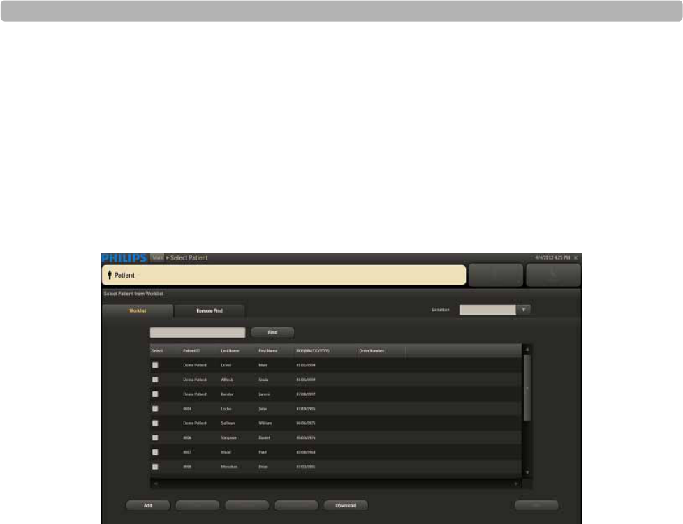
The Patient Session
3-4 ST80i Stress Test System Instructions for Use
Using the Patient Worklist
When you click Patient on the Main screen, you are taken to the Select Patient screen, where
you begin a patient session by selecting the patient for the exam.
The Select Patient screen includes two tabs:
Worklist
Remote Find
Figure 3-1 Select Patient Screen
Use the Worklist tab to manage patient information. The Worklist enables you to pre-register
up to 200 patients. The Worklist database is populated by downloading patient orders or ADT
data from a Hospital Information System (HIS), by manually entering information into the
Worklist window, or by remote retrieval of information.
Use the Remote Find tab to do a remote search for a patient using several data points. ST80i
provides an interface with the Philips ECG Gateway or a DICOM server so that you can do the
following before conducting an exercise stress test:
Download a patient's data from DICOM server via ECG Gateway
Download a patient's orders or ADT data from the hospital HIS system (via ECG
Gateway)
Worklist Tab
The Worklist tab of the Select Patient from Worklist screen is used to manage the patient
information list, including:
Adding a new patient
Finding a patient
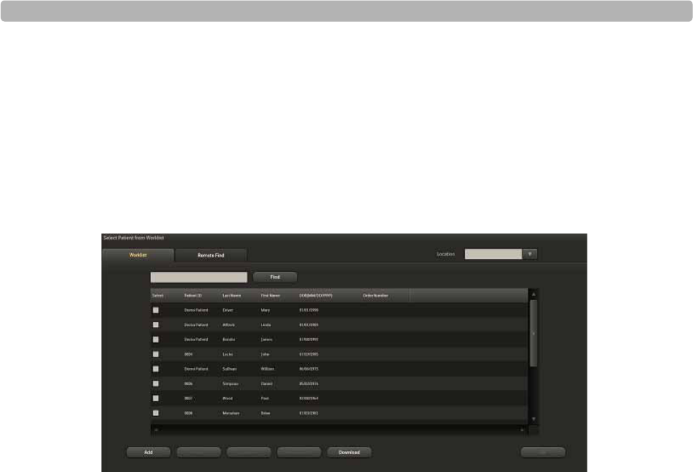
Using the Patient Worklist
ST80i Stress Test System Instructions for Use 3-5
Editing a patient profile
Deleting one or more patient information records
Downloading orders or pre-registered patient information
Selecting a patient to begin the exercise stress test
On the Worklist tab, you can also use the column headings to sort each list.
Figure 3-2 Worklist Tab
Patient Information Management
ST80i displays and reports key patient demographic information such as the patient name,
hospital ID number, etc. Some settings are mandatory and configurable. Some settings are set
to ON or OFF.
There are two ways to access Patient Demographic information:
From the Worklist tab before the test:
1Place a checkmark by the patient's name.
2Select the Edit button.
The Edit Patient Information screen is displayed.
From the Test screen during a patient session:
1Click on the patient's name from the top bar.
The Edit Patient Information screen is displayed.
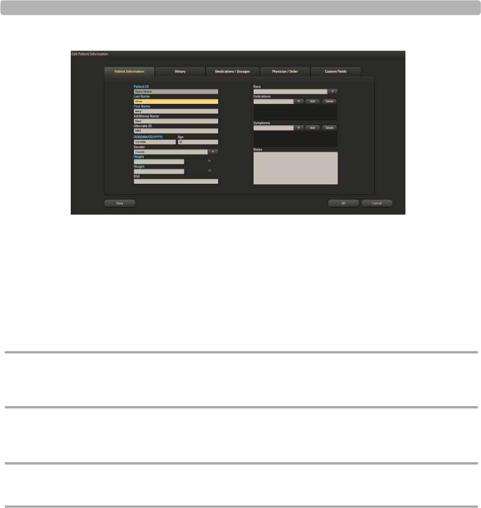
The Patient Session
3-6 ST80i Stress Test System Instructions for Use
Figure 3-3 Edit Patient Information Screen
You can also access this information from the Report screen. See “Working with Reports” on
page 4-1.
Patient Information Fields
ST80i supports predefined and user-defined patient information fields. The predefined patient
information fields are shown in the Patient Information tab of the Edit Patient Information
screen. The patient information fields are configured as mandatory or not. Mandatory fields
are displayed in blue text.
CAUTION For better algorithm output, the Patient Information Fields that may affect algorithm output need to be
enabled and complete. At a minimum, the Patient ID, Last Name, First Name, DOB, and Gender must
be configured as mandatory fields that will be identified on the Test screen.
To configure or change mandatory patient information fields, see the ST80i Installation and
Configuration Guide.
CAUTION Specific patient data is required for each interpretation. If entered patient data are found to be
incorrect, the ECG file may be edited and a new display and/or report can be printed.
Add a New Patient to the Worklist
To manually add a new patient name to the Worklist
1Click the Add button.
2In the Add New Patient screen, fill in the patient name and patient information in the
required fields for each of the following tabs:

Using the Patient Worklist
ST80i Stress Test System Instructions for Use 3-7
– Patient Information
–History
– Medications/Dosage
–Physician/Order
–Custom Fields
3If you want to:
– Save the information and return to the Worklist, click Save.
– Save the information and begin the stress test, click OK.
NOTE When mandatory fields are missing, you will be warned with a pop-up message box. If these fields
are changed, a warning message pops up and the resting ECG will be re-interpreted.
Find a Patient
You can find a patient already listed in the Worklist by using specific demographic
information as search criteria.
To find a patient in the Worklist
1Type one of the following into the search field: Patient ID, last name, first name, or order
number.
2Click Find.
The Worklist displays only the patient(s) matching the search criteria.
3Click the Back button to restore the full list of names.
Edit Patient Information
In Worklist, you can edit or review patient information by using the Edit button.
When you select a patient name, the Edit button becomes active.
To edit patient information in the Worklist
1Place a checkmark by the patient's name.
2Click the Edit button to open the Edit Patient Information screen.
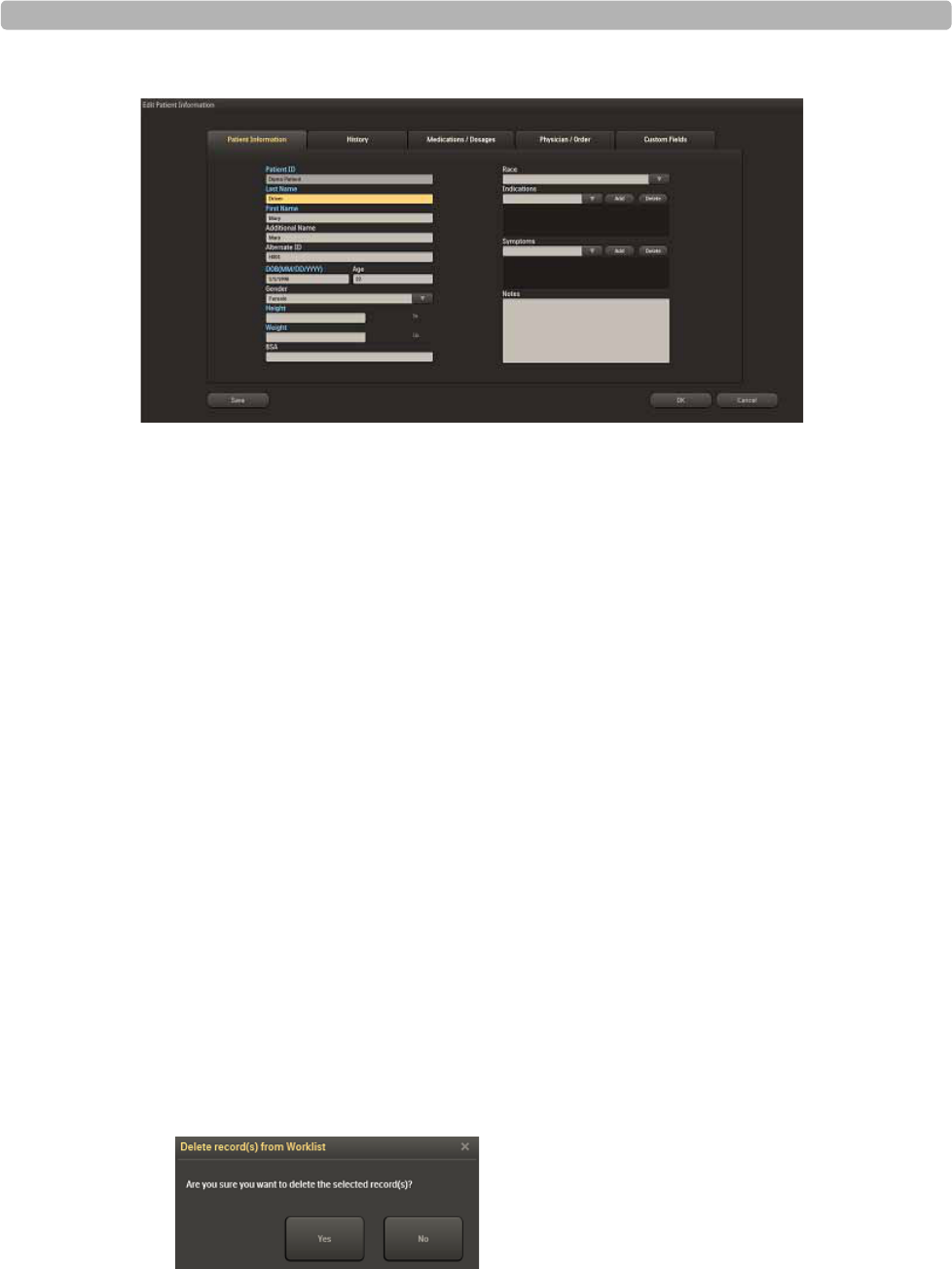
The Patient Session
3-8 ST80i Stress Test System Instructions for Use
Figure 3-4 Edit Patient Information Screen
3Update or edit the patient information in each of the following tabs, as required:
– Patient Information
–History
– Medications/Dosage
–Physician/Order
–Custom Fields
4If you want to:
– Save the information and return to the Worklist, click Save.
– Save the information and begin the stress test, click OK.
NOTE When mandatory fields are missing, you will be warned.
Delete a Patient Name
You can delete one or many patients from the Worklist.
To delete a patient name from the Worklist
1Place a checkmark by the patient's name. You can check more than one patient name to
delete.
2Click the Delete button.
3Select Yes from the pop-up box: “Delete record(s) from Worklist.”
Figure 3-5 Delete Record(s) from Worklist Window

Using the Patient Worklist
ST80i Stress Test System Instructions for Use 3-9
Download Preregistered Patient Information
With ST80i, you are able to download preregistered patient information by accessing the order
or ADT server via the network. The local patient information that you download from remote
server or manually add will be stored in a local database. This optional feature permits the
creation of a preregistered patient list.
To download orders -- procedure in development...
1Click Location
2
3
Review a Previous ECG
To review a patient's previous ECG Report
1Place a checkmark by the patient's name.
2Click the Previous ECG button.
The Previous ECG Report List is displayed.
Figure 3-6 Previous ECG Report List Screen
3Place a checkmark by the patient's name.
4Click the View Report button.
The report opens in pdf format.

The Patient Session
3-10 ST80i Stress Test System Instructions for Use
Figure 3-1 Report Screen
5Click the Back button to return to the Select Patient from Worklist screen.
Select a Patient
When you are ready begin the patient session for a patient, select his or her name from the
Worklist.
To select a patient to begin the patient session
1Place a checkmark by the patient's name.
2Click OK or press Enter.
This brings you to the first screen of the test: Pre Exercise
Remote Find Tab
The Remote Find tab of the Select Patient from Worklist screen allows you to do a remote
search for a patient using several data points. With this feature, you are able to select one or
more entries from the search results list and save them to the Worklist.
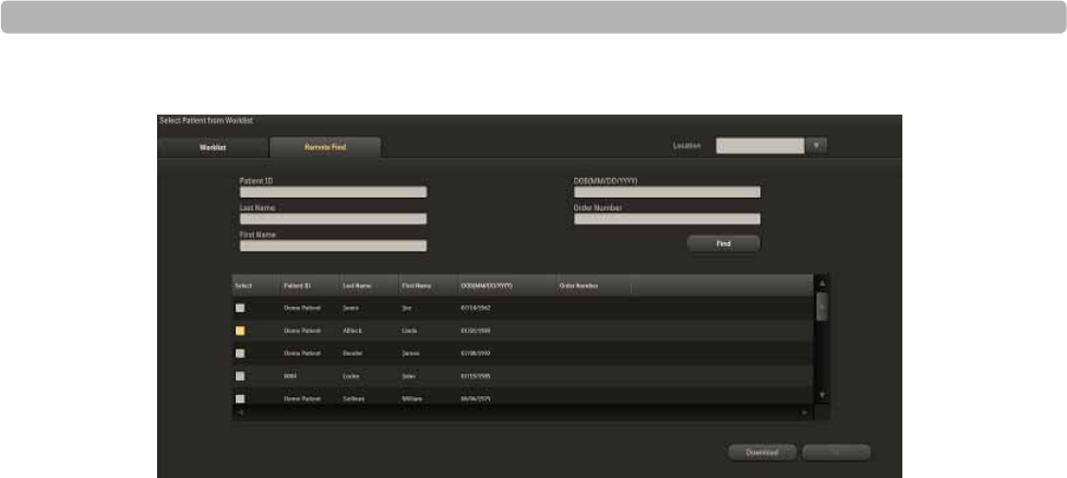
Using the Patient Worklist
ST80i Stress Test System Instructions for Use 3-11
Figure 3-2 Remote Find Tab
To do a Remote Find
1Select the location from the Location drop-down list.
2Fill in one or all of the following fields:
– Patient ID
–Last Name
–First Name
– DOB (MM/DD/YYYY)
– Order Number
3Click the Find button.
Patient's name appears in the Remote Find list.
4Place a checkmark by the patient's name.
5Click the OK button to start a patient session.

The Patient Session
3-12 ST80i Stress Test System Instructions for Use
Before the Patient Session
The exercise stress test process requires some advance preparation before running the patient
session. Advance preparation includes the following:
Checking the Wireless Patient Interface Module (PIM)
Checking the equipment connection (treadmill/ergometer), if used
Setting up the Pharma test
Once advance preparation is complete, the patient session follows a series of typical steps -
from preparing the patient to the final review of the exam.
Wireless Patient Interface Module (PIM)
The wireless PIM is a small data acquisition device that samples patient ECG signals and
sends the processed signals to ST80i. The wireless PIM assembly contains the signal
acquisition electronics, patient isolation circuits, and system interface circuits. The patient lead
set connects to the patient electrodes on one end and plugs into the wireless PIM on the other.
Figure 3-3 Wireless PIM
The wireless PIM digitizes the ECG signal and down-samples the ECG data before
transmitting ECG data to ST80i. The wireless PIM uses high and low pass filters to produce
filtered ECG data within certain band.
The wireless PIM performs lead signal quality detection to determine if a lead is not connected
to patient or electrode/patient contact impedance is excessively high.

Before the Patient Session
ST80i Stress Test System Instructions for Use 3-13
The wireless PIM can also be commanded by the host application to transmit on a
user-selected channel to manually override the automatic system driven settings to avoid
wireless interference. See the ST80i Installation and Configuration Guide for information on
configuring a wireless channel for communication.
The wireless PIM shows the following information:
Wireless signal quality indicator:
Wireless performance and signal strength are monitored on the currently used RF channel.
The wireless PIM’s signal quality icon indicates the connection status. If a channel has
excessive interference, the wireless PIM will automatically determine a clearer channel
with higher signal strength and coordinate with the Advanced Interface Module (AIM) to
switch to the new channel.
Lead-off indication for every lead:
ST80i recognizes when an electrode is not connected and displays that information on the
graphic of a human torso on both the wireless PIM and ST80i interface.
Power indication for battery:
The wireless PIM is battery-powered and the battery voltage is monitored to ensure that
the battery is not overly discharged. The remaining battery capacity is displayed in the
wireless PIM’s power indicator lights within the battery icon. These lights blink every 5
seconds when the PIM is in use.
In addition, when all patient leads are being connected prior to a test, a low-battery alert
warns if there is not enough capacity in the battery to complete test.
ST80i also provides an audible and visual alert on the application screen as a warning that
the battery is discharged to the point where PIM is expected to shut down shortly.
The wireless PIM uses off-the-shelf (OTS) disposable AA alkaline batteries for its power
source. For the disposable AA battery, the system has been designed to provide approximately
one week of battery service life for a “typical” user environment. .
CAUTION ST80i only supports 1.5V AA alkaline batteries for the PIM. Replace the battery if a low-battery alert
appears before the stress test starts.
CAUTION If you use off-the-shelf rechargeable AA-size batteries, the remaining capacity indication may be
inaccurate.
CAUTION If you use OTS rechargeable batteries, you will need to provide a compatible recharger unit for their
batteries that is independent of the ST80i. To ensure safe use and adequate maintenance of
rechargeable batteries, follow the battery manufacturer’s instructions for use.

The Patient Session
3-14 ST80i Stress Test System Instructions for Use
When using the wireless PIM, refer to the ST80i Wireless Patient Interface Module
Instructions for Use for details on its preparation, configuration, and use.
If your facility is using more than one PIM, each one must be added to the ST80i application
under Settings (System Settings; I/O Devices). When you connect the patient to one of the
PIM devices, you also need to verify the address on the device with the address that shows up
on the Pre Exercise screen.
To preconfigure multiple PIM addresses, see the ST80i Installation and Configuration Guide.
Checking the Treadmill/Ergometer Connection
During the entire stress test, the host-side application validates the response from treadmill/
ergometer to ensure the communication between PC and treadmill/ergometer is successful.
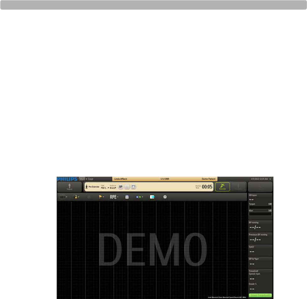
Starting a Patient Session
ST80i Stress Test System Instructions for Use 3-15
Starting a Patient Session
When you select a patient from the Worklist for the stress test, you are immediately brought to
the Pre Exercise screen. Based on your user account settings at log-in, a preconfigured profile
is loaded for the stress test protocol.
Select the Patient
To select a patient from the Worklist
1Click Patient on the Main screen.
2Place a checkmark in the patient name line and click OK, or double-click the patient’s
name.
The Pre Exercise screen is displayed. The patient’s name and date of birth appear on the
Title Bar along with the patient ID. The selected protocol is shown on the Procedure Bar.
Figure 3-4 Pre Exercise Screen
By default, the application displays the real-time ECG waveforms in the format specified in
the selected user profile.
To change the real-time ECG display, see “Using the Toolbar Icons” on page 2-15.
When Bruce is selected as the protocol, the Start Treadmill button appears in the Side Panel.
If you select Cycle as the protocol for the patient, the Load Ergometer button appears instead.

The Patient Session
3-16 ST80i Stress Test System Instructions for Use
Select the Wireless PIM
The wireless PIM contains a power on/power off button. Before connecting a patient to the
PIM, check the battery status and the wireless signal quality. You will also need to confirm
that you are using the right PIM by checking the PIM address.
By default, you will see PIM1 as the first device on the Pre Exercise screen. When you click
on the device name, a unique address appears which is used to identify that specific PIM. If
there are multiple PIMs registered, they will appear as named during preconfiguration.
To select the wireless PIM
1Click the PIM drop-down menu.
2Click the PIM device to be used (by name).
3To ensure a correct match, confirm the unique address on the wireless device with the one
you have selected on the Pre Exercise screen.
4Press the PIM button on the device to power it on (if it is powered off).
The PIM wireless status gives feedback that the PIM is selected to communicate with the
application.
CAUTION The user should follow the correct procedure to select the PIM when multiple PIMs are detected.
To ensure proper wireless function of the PIM
Press the PIM’s “light” button to display battery strength.
A battery icon on the ST80i exercise screen also shows the remaining capacity of the
wireless PIM battery.
ST80i also provides an audible and visual alert on the application screen as a warning that
battery is discharged to the point where PIM is expected to shut down shortly.
NOTE To save the battery power, the PIM can be preconfigured to power off automatically when there is no
action on the PIM for a predefined period.
To preconfigure PIM Power Saving, see the ST80i Installation and Configuration Guide.
Preparing the Patient
ST80i Stress Test System Instructions for Use 3-17
Preparing the Patient
Good ECG technique is very important to achieve the best quality results.
Instructing the Patient about the Test
Before attaching the electrodes, greet the patient and explain the procedure. Explaining the
procedure decreases anxiety and informs the patient about what to expect. You may also click
the Explain Test button on the Main screen to play an audio file that explains the test to the
patient.
NOTE ST80i ships with a default audio file that explains the exercise stress test; however, you may record
your own audio file and configure ST80i to play this file when the user clicks the Explain Test button.
For more information, see the ST80i Installation and Configuration Guide.
Privacy is important to relaxation. When possible, prepare the patient in a quiet room or
area where others cannot see the patient.
Reassure the patient that the procedure is painless.
Make sure the patient is comfortable. The patient’s arms and hands must be relaxed.
Instruct the patient to rest their hands on the handrails and not grasp the handrails tightly.
The more relaxed the patient is, the less the ECG will be affected by noise.

The Patient Session
3-18 ST80i Stress Test System Instructions for Use
Preparing the Skin
Thorough skin preparation is very important. The skin is a poor conductor of electricity and
frequently creates artifact that distorts the ECG signal. By performing methodical skin
preparation, you greatly reduce the potential for myographic noise and baseline wander,
ensuring high-quality printouts and displayed data. There is a natural resistance on the skin
surface due to dry, dead epidermal cells, oils, and dirt.
To prepare the skin
1Shave hair from electrode sites, if necessary. Excessive hair prevents a good connection.
2Wash the area thoroughly with soap and water.
NOTE Do not use alcohol to clean the skin.
3Dry the skin vigorously with a gauze pad to increase capillary blood flow to the tissues
and to remove the dead, dry skin cells and oil.
4Use an abrading pad to lightly scratch an “X” pattern into the skin, taking care to avoid
excessive abrading.
Attaching the Electrodes/Lead Wires
Placement of the electrodes changes depending on the stage:
Supine for a resting or baseline ECG
Standing for Exercise Phase
ST80i supports the use of 12-lead wireless PIMs. The 12-lead wireless PIMs connect to the
AIM and support 10 electrodes. Using AAMI/IEC labeling, these electrodes are:
Right Leg [RL/N]
Left Leg [LL/F]
Right Arm [RA/R]
Left Arm [LA/L]
Chest leads [V1/C1, V2/C2, V3/C3, V4/C4, V5/C5, and V6/C6]
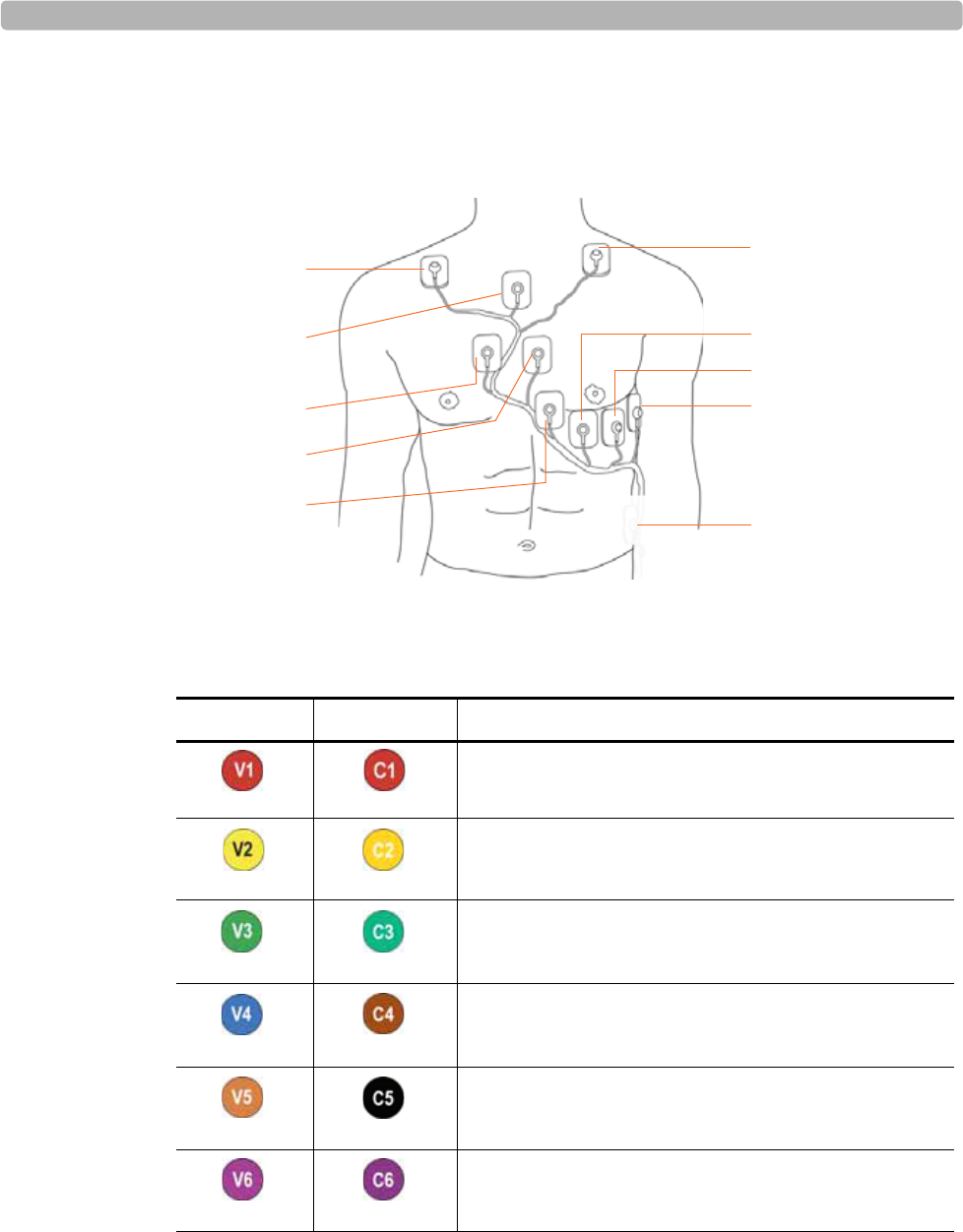
Preparing the Patient
ST80i Stress Test System Instructions for Use 3-19
All leads are acquired simultaneously. Review the following lead wire labeling and electrode
placement information in Figure 3-5 and Table 3-1 to ensure a quality ECG.
Figure 3-5 12-Lead Electrode Placement (AAMI/IEC)
Table 3-1 Leads and positioning
AAMI Lead IEC Lead Electrode Position
Right side of the sternum in the 4th intercostal space
Left side of the sternum in the 4th intercostal space
Midway between V2 and V4
Left midclavicular line in the 5th intercostal space
Between V4 and V6
5th intercostal space, left midaxillary
V3/C3
RL/N
RA/R
V1/C1
V2/C2
V4/C4
V5/C5
V6/C6
LA/L
LL/F
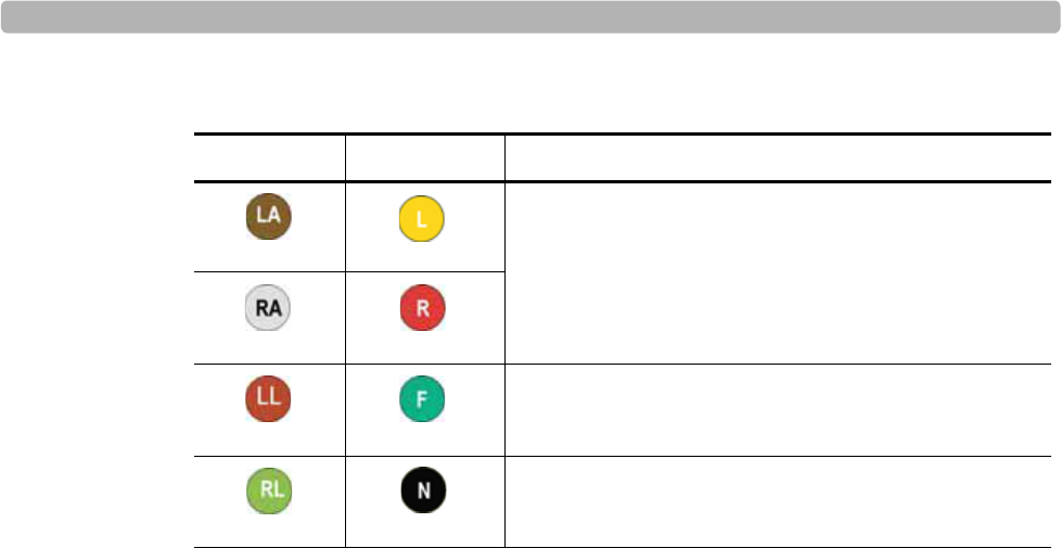
The Patient Session
3-20 ST80i Stress Test System Instructions for Use
To attach the electrodes to the patient
1Place the gel area of the electrode over the center of the prepared area, using the
positioning described in Table 3-1 and illustrated in Figure 3-5; then press the adhesive
ring into place.
– Avoid pressing the center of the gel area; this might hinder conduction.
– Place the electrodes on the soft tissue of the arms, avoiding muscle. See limb lead
placements notes next.
Lead placement is similar to standard 12-Lead ECG placement; however, limb leads are
modified, as follows:
– Right Arm and Left Arm leads should be placed close to the shoulders on the clavicle
bone, away from the muscular areas to avoid muscle interference.
– The Right Leg lead is typically placed on the sternum midway between the arm leads
and V1 and V2 leads.
– The Left Leg lead should be placed on a rib, below V6 by about 2 fingers, in the lower
left area of the patient’s chest (avoiding flabby areas and the belt). This may need
adjustment depending on body habits.
2Ensure the electrodes are firmly attached.
A good test for firm electrode contact is to try to move it. If it moves easily, the electrode
connection is too loose. Do not allow electrodes to move in any way.
3Have the patient raise their arms over their head. This will help verify good lead
placement and no strain on the electrodes.
Place the limb electrodes for the arm directly on the
clavicle bones (away from major muscles)
Below V6 on the ribcage
On the sternum, midway between the clavicle and the
4th intercostal space
Table 3-1 Leads and positioning
AAMI Lead IEC Lead Electrode Position

Preparing the Patient
ST80i Stress Test System Instructions for Use 3-21
Change from Limb Lead to Mason-Likar
To attach the electrodes for the Supine (Resting) phase
1Place the upper body electrodes on the patient.
2Have the patient lie down.
3Attach the leg electrodes.
4Take the BP measurement.
5Record the ECG.
6Label the ECG “Supine.”
To attach the electrodes for the Exercise Phase (Standing)
1Disconnect the limb leads from the patient.
2Remove the leg electrodes.
3Hold the PIM as the patient stands.
4Place the limb electrodes on the torso.
5Attach the limb leads.
6Put on the belt and PIM.
7With the patient standing, record the ECG and label “Standing.”
8The patient is now ready to move to the exercise device.
9Explain the test.
Connecting the Patient to the Wireless PIM
All of the ST80i lead sets are designed to share the same connector that will plug into the
mating connector on the wireless PIM. Refer to the ST80i Wireless Patient Module
Instructions for Use for details on its preparation, configuration, and use.
To connect the patient to the wireless PIM
1Plug the lead set connector into the mating connector on the wireless PIM.
Ensure that lead wires do not bump or rub against anything.
2Place the wireless PIM into the PIM holder. The PIM holder is designed to keep the PIM
steady, thereby minimizing movement of the lead wires and ECG signal artifacts. The
PIM holder is adjustable up to a patient waist size of 57".
Wireless PIM Button Functions
The wireless PIM has one button that you can use to:

The Patient Session
3-22 ST80i Stress Test System Instructions for Use
Power on/off the PIM
Check PIM battery status, wireless link quality, and lead contact quality
When requested to check battery status, the wireless PIM will provide indication of estimated
battery power remaining.
When requested to check status of connection to the host system, the wireless PIM will
indicate relative signal strength based on the measured signal quality for the link to the host
receiver.
When requested to check lead/electrode connections, the wireless PIM will indicate “Poor
Lead Signal Quality” condition for any patient electrode connection where the measured
impedance is considered excessively high for good quality, low noise ECG measurements.
You are able to check the lead signal quality of lead connections while hooking up and
preparing patient in an area outside of the range of the system’s radio connection.
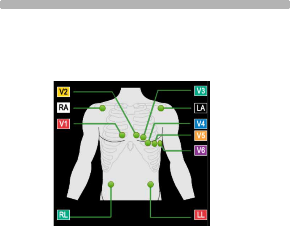
Preparing the Patient
ST80i Stress Test System Instructions for Use 3-23
Checking the Lead Map
To check the Lead Map
Select Show Lead Map from the Hide/Show View icon on the Pre Exercise or Exercise
screen. A color-coded anatomical diagram displays the lead connections.
Figure 3-6 Lead Connections
If a lead is off, a red “X” is displayed on the lead map and red, dashed flat line is displayed
in the real-time ECG view. On the PIM, this condition is verified by a yellow LED light.
For more details on checking the lead quality connection, see “About the Lead Map” on
page 2-19.
For more details about adjusting the filter, see “Gear (Quick Settings)” on page 2-30.
NOTE Using medical tape to fix the lead wires to the chest may help to minimize strain applied to electrode
connections, thus reducing noise and possibility of leads-off condition occurring.
Checking Signal Quality
ST80i can recognize when an electrode is not connected, and display that information on both
the wireless PIM and the Exercise screen. As you adjust the electrodes, the display is updated
to reflect changes in the connectivity of the signal. The lead-off condition will be saved with
the data and will be indicated on any printed reports which contain that data.
The waveform appears on the real-time display as green. When a lead-off condition is
detected, the corresponding lead(s) will be indicated on the real-time display as a red dashed
line; when printed, this will also appear as a dashed line.
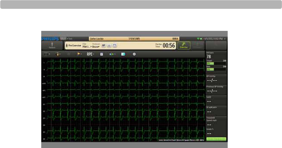
The Patient Session
3-24 ST80i Stress Test System Instructions for Use
Figure 3-7 Red Dashed Line Showing Leads-Off Condition for V4
ST80i will also provide an indication to the operator when the front-end is inoperative and
cannot acquire signal. The indications are lead-off on all leads and the wireless signal quality
indicator lights. This condition will be saved with the data and will be indicated on any printed
reports which contain that data.
Figure 3-8 Faulty Lead Display Example (V1)
If the screen shows one or more faulty lead connections, re-prep the patient (page 3-17) and
replace the electrodes (page 3-18), as necessary, until the display shows satisfactory tracings.

Preparing the Patient
ST80i Stress Test System Instructions for Use 3-25
Filtering
When you open the ST80i application, the active settings of the filters are associated with your
user profile. The same filter settings apply to both displayed and printed waveforms. The filter
settings are printed with the report.
The smart filter can be enabled or disabled through the Config screen User Profile tab’s Filters
button. The same filter settings apply to both displayed and printed waveforms. The filter
settings are printed with the report.
The filtering techniques developed for ST80i permit the user to identify any clinically
significant ST deviation and will not degrade the integrity of the relevant ECG signal content,
specifically the ST segment (deviation and slope). This capability is especially important
during stages of exercise (stage three and later) where more motion and muscle artifact is
present, which could otherwise obscure the ST deviation.
The ECG data is stored in its unfiltered state (0.02 – 300Hz, all filters off) and user-selected
settings are stored with the ECG.
NOTES The ECG data is filtered at 0.05-150Hz before being analyzed by the algorithm. This filter is called the
algorithm filter and cannot be turned off by user. The algorithm filter is independent from other filters
and is neither controlled by the user nor affects the saved ECG data.
All filters can be turned on or off as needed to improve signal quality except for the algorithm filter (as
described above) and minimum filters (0.02Hz high pass filter and 300Hz low pass filter).
If needed, you can change the default filter settings. For details on filter settings, see “Gear
(Quick Settings)” on page 2-30.
Sync Output
ST80i supports two analog ECG output signals and one TTL ECG Sync output on the AIM.
The AIM accepts real-time ECG data from the wireless PIM and dispatches the data to the PC
and output channels. This signal serves as a synchronization signal for coordination of timing
between ST80i and another device, such as imaging devices.
ST80i also supports the TTL and Analog output options, which allow selectable ECG signals
to be sent to Echo system, NIBP and/or SpO2 for further clinical analysis.
The analog-out signals are amplified.
TTL/Analog Output Option:
Specifying the Sync Lead
– User can select the ECG lead used for the TTL/Analog Output.

The Patient Session
3-26 ST80i Stress Test System Instructions for Use
The source signal of the analog ECG and TTL Sync for each output channel can be selected by
software from any of the available ECG leads separately. The amplify ratio for the Analog
ECG Output can also be configured independently.
To change Analog and/or TTL Output settings during a patient session, see “Gear (Quick
Settings)” on page 2-30.
To configure Analog and TTL Output, see the ST80i Installation and Configuration Guide.
WARNING Both analog ECG output and TTL sync output are not in real time: there is a delay between the
patient’s physiological activity and the appearance of its representative signal at the external port.
This signal should not be used for analysis.
NOTES ST80i monitors interference and signal strength and automatically selects a clearer frequency band
when excessive interference exists.
Software design also ensures that the waveform or lead label can be correctly displayed, stored, and
printed, to avoid data conversion or lead combination errors.

Preparing the Patient
ST80i Stress Test System Instructions for Use 3-27
Pre Exercise Phase
The Pre Exercise phase is used to start the patient on the treadmill or the ergometer. The phase
is preset to run for 3 minutes with the speed setting on 01:00 and the elevation is set at 0%.
Figure 3-9 Treadmill Speed and Grade
Note that the Pre Exercise time is separate from the Exercise time.
Before the Pre Exercise phase begins with the patient on the treadmill, the following steps are
recommended:
Baseline ECG (resting or standing)
Baseline Blood Pressure - manual or NIBP
Baseline Sp02
Static ECG Resting Interpretation
Once the waveforms are satisfactory, you are ready to acquire a baseline (resting or standing)
ECG. ST80i allows you to acquire and print a 12-lead resting ECG with or without
interpretation when the patient is supine or when using the Mason-Likar lead placement. This
data will appear as part of the Final ECG Report.
ST80i will provide resting ECG interpretation for all available lead configurations, using the
latest Philips DXL algorithm at resting ECG for traditional limb lead placement as well as
Mason Likar.
WARNING To get the most accurate interpretation during resting ECG, use traditional limb lead
placement.
When the algorithm finds excessive artifact or AC noise, it will give a related warning/error
string. The string will be printed on the report and be saved when saving the report. The
algorithm also reports wrong lead placement.
See “Filtering” on page 3-25 regarding artifact or AC noise.
The Patient Session
3-28 ST80i Stress Test System Instructions for Use
To acquire a resting ECG without interpretation
1Have the patient in a supine position.
2Click 12 Leads Print button on the Toolbar to obtain a 12-lead resting ECG without
interpretation.
To obtain a 12-lead resting ECG without interpretation:
1Click the Event button.
2From the drop-down menu, select Supine.
To acquire a 12-lead standing ECG without interpretation
1Have the patient in a standing position.
2Change the lead position to Mason-Likar.
3Click the Event button.
4From the drop-down menu, select Standing.
5Click the 12 Leads Print button on the Toolbar to obtain a 12-lead resting ECG without
interpretation.
After a few seconds, the ST80i system prints a full 12-lead resting ECG with
measurements.
To obtain a 12-lead resting ECG with interpretation
Select an event while in Pre Exercise.
After a few seconds, the ST80i system prints a full 12-lead resting ECG with
measurements and interpretation text.
The next step is to connect the patient to the blood pressure monitor and record a baseline
blood pressure.

Preparing the Patient
ST80i Stress Test System Instructions for Use 3-29
NIBP & SpO2
ST80i supports optional SpO2 and motion-tolerant Non-Invasive Blood Pressure (NIBP)
devices. ST80i automatically collects the NIBP through a cuff. The patient’s SpO2 is collected
in real-time through a sensor.
NIBP and SpO2 are real-time numeric displays for the NIBP and SpO2 values for an entire
study or for a single instance. They can be manually measured and the values can be
overridden.
During the stress test, NIBP and SpO2 are measured according to the intervals defined in the
exercise protocol and are continually displayed on the screen. This will be recorded in the
BPmmhg field in the Side Panel and also on the ECG. The SpO2 measurement will also be
recorded in the Side Panel in the SpO2 field.
If enabled, there are also audible prompts for NIBP and SpO2. To enable audio prompts, see
the ST80i Installation and Configuration Guide.
To connect the patient to the NIBP device
1Place the cuff on the patient.
2Take a pre-stress NIBP connection test to determine if the cuff is correctly placed on the
patient and to ensure NIBP measurements throughout the stress test.
To connect the patient to an SpO2 sensor
Place the SpO2 sensor on the patient’s finger. connection test. The screen should display
an SpO2 value.
Override NIBP and SpO2
When you enter or acquire blood pressure values according to the pre-programmed automatic
prompts or at any other times during the test, for each recording, the blood pressure value,
phase, and total time of the phase at the time of the acquisition are captured.
The automatic timing of blood pressure measurements is established in the exercise protocol.
You can, however, take blood pressure measurements at any time during each stage by using
the BP button. Or you can enter the measurement manually, after taking the patient's blood
pressure.
When you override the values of NIBP and SpO2, they will be displayed in the Stage Report
and the Final Stress Report.
NOTE Once the NIBP or SpO2 is manually overwritten, ST80i no longer updates the real-time NIBP or SpO2
values from the NIBP monitor.

The Patient Session
3-30 ST80i Stress Test System Instructions for Use
To take a blood pressure measurement (if the patient is connected to a blood pressure
monitor) other than a timed BP
Click the BP button.
The current blood pressure measurement displays in the BP mmhg field.
The previous blood pressure measurement displays in the Previous BP mmhg field.
To manually enter the blood pressure measurement when no NIBP device is connected
1After you take the patient's blood pressure, click the BP mmhg field.
2In this field, insert the latest blood pressure measurements.
3Click OK.
The display shows the manually entered measurements.
The previous blood pressure measurement displays in the Previous BP mmhg field.
To override the SpO2 -- procedure in developement---
NOTE ST80i software validates the input values of NIBP and SpO2 before they take effect to ensure that the
numbers fall within an expected physiological range.
For how this information will be displayed in the Final Report, see “Working with Reports” on
page 4-1.
After taking the baseline measurements, you are now ready to instruct the patient in the proper
use of the equipment.
Starting the Patient on the Treadmill or Ergometer
The start and stop control for the treadmill or ergometer appears in the side panel. There is also
a start and stop button on the treadmill.
You can also manually control the speed and grade of the treadmill during any stage in the
Exercise test. See “Controlling the Treadmill or Ergometer” on page 3-35.
To start the patient on the treadmill
1Show the patient the location of the emergency stop button.
2Have the patient straddle the belt.
3In the ST80i application, click Start Treadmill.
This button changes to Stop Treadmill.
The treadmill starts at the preselected speed and elevation set for the protocol.

Preparing the Patient
ST80i Stress Test System Instructions for Use 3-31
4Allow the patient to get acclimated to the movement of the belt, and then provide the
patient with the following instructions:
– Keep your body straight and head up.
– Walk in a normal walking position with arms at your sides, or place your hands lightly
on the handrails for stability but do not bear down with too much gripping force.
– Use as little upper-body motion as possible and stay near the front of the treadmill.
You are now ready to begin the Exercise phase.
To begin the Exercise phase
Click the Exercise button on the Procedure bar.
The Exercise screen is displayed.
Exercise Phase
At the start of an exercise stress test, CAlg has a “Learning Phase” where it automatically
selects the initial 12-lead dominant QRS complex. CAlg removes baseline wander and aligns
successive non-noisy complexes of similar shape and then averages them together to form a
noise-reduced representative beat. As new, similar complexes arrive, they are added to the
representative beat, and old complexes are removed from it. When CAlg stops finding good
matches for the representative beat and all old complexes have been removed, it will
automatically detect a new dominant morphology and build a new representative beat.
CAlg makes ST measurements on the noise-reduced representative beat.
During the test, you can print 12-lead ECGs automatically or manually. You can choose any of
the following display choices:
12 leads
6x2 leads
6 leads
3 leads
You can start the Exercise phase of the test at any time; however, a warning message will be
popped up if not all 12 leads ST value is gotten from the algorithm.
Conducting the Exercise Stress Test
When you move into the Exercise phase of the test, the treadmill loads the settings associated
with the first stage of the test, and the stage and phase clocks start counting.
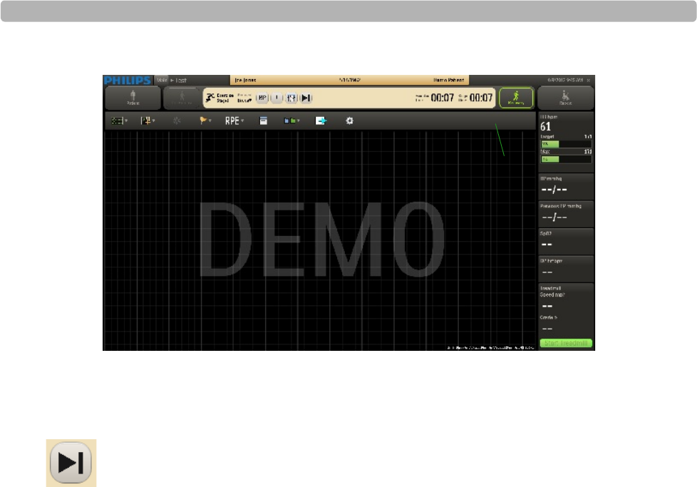
The Patient Session
3-32 ST80i Stress Test System Instructions for Use
Figure 3-10 Exercise Screen
The exercise time builds cumulatively as the patient completes each stage. However, with each
new stage, the stage clock restarts at 00:00. The stage time, speed, and elevation for each stage
are defined by the protocol.
If you want to move to the next stage, without waiting for the system to automatically change,
you can click the Advance button on the Procedure bar. This starts a new stage and a new
stage time, but the exercise time continues to build.
If the patient can no longer continue exercising, you can end the Exercise phase of the stress
test by selecting Recovery (or by pressing the Stop Treadmill button if necessary). The
Recovery phase is preset to slow down the treadmill and lower the elevation.
Monitoring the Patient
During the Exercise phase:
The patient walks on the treadmill or peddles the ergometer, unless the patient is unable to
exercise or is not using an exercise device.
You record blood pressure, observe events, and record RPE, while closely monitoring the
patient.
You can switch from an automated protocol to manual operation, giving you full control
over the treadmill. To switch to manual control, see “Controlling the Treadmill or
Ergometer” on page 3-35.
You can change the display parameters, as needed during the Exercise phase. For details,
see “Using the Toolbar Icons” on page 2-15.
The Exercise phase comprises several stages, which are defined by the selected protocol.
For a breakdown, see Appendix B, “Protocol Reference”.
Ask Corey what this means...
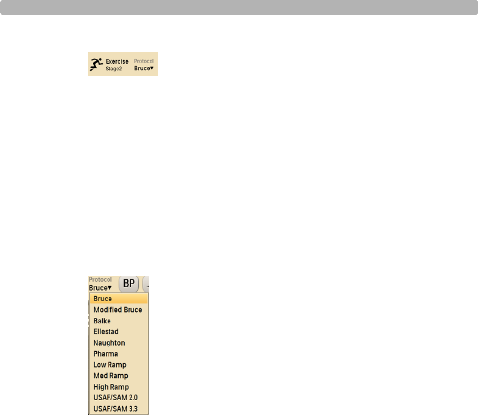
Preparing the Patient
ST80i Stress Test System Instructions for Use 3-33
Figure 3-11 Exercise Stage and Protocol
In general, you will most likely use the standard settings as specified by the profile and
protocol selected.
Changing to Another Protocol
If you need to switch to a different protocol at any time during the Exercise phase of the test,
use the drop-down arrow by the current protocol to select a new protocol. The phases and
stage settings associated with the newly selected protocol are loaded into ST80i.
See the ST80i Installation and Configuration Guide for setting default protocols.
To change to another protocol
1Click the drop-down arrow by the current protocol shown in the Procedure Bar.
Figure 3-12 Protocol Drop-Down List
2Select the new protocol from the list
The time on the clock resets to 00:00 for the next stage.
When you change the protocol, the test advances to the selected protocol, starting at the
beginning of the next stage. Both the speed and grade settings change to reflect the new
protocol.
NOTE You can also switch back to the previous protocol. When you do this, a new stage appears in the
Procedure Bar and the time clock adjusts back to 00:00.
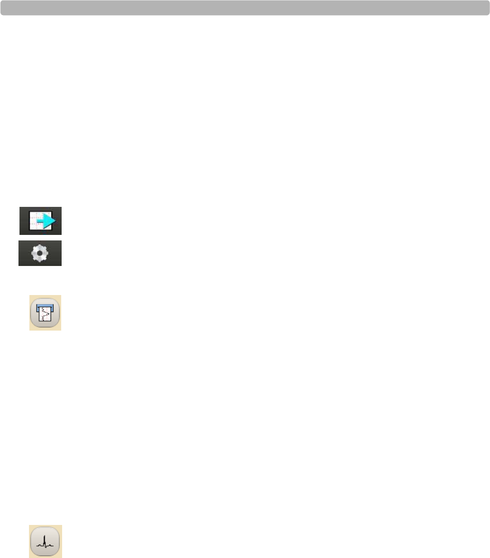
The Patient Session
3-34 ST80i Stress Test System Instructions for Use
Rhythm Print
You can print a continuous rhythm strip directly from the ST80i screen at any point during the
test. The system generates a continuous report (configurable from 1 to 12 leads) of the leads
specified in the configuration for the particular profile. For details, see the ST80i Installation
and Configuration Guide.
The continuous rhythm strip contains the patient's name and the current date and time. You
can generate continuous rhythm strips during all phases of a test.
Any scheduled automatic 12-lead or manually generated events that occur during continuous
rhythm printing are saved for later review or printing and are included in the final report.
To change the settings for Rhythm Printing before printing the Rhythm Strip
1Use the Page icon to set the top of the page
2Use the Gear/Quick Settings icon [Gear/Quick Settings Rhythm Print] to set the
Leads, Limb Gain, Chest Gain, and Speed.
To print a continuous strip
1Click the Rhythm Print icon.
A continuous Rhythm Strip will print.
2Click the Rhythm Print icon again to stop the strip from printing.
12-Leads Print
The timed printing of the 12-Lead ECG is based on the Exercise Protocol settings that are
preconfigured on the Config screen’s Exercise Protocol tab. For details, see the ST80i
Installation and Configuration Guide.
In addition to the timed printing of an ECG, you can also generate 12-lead ECGs during all
phases of the test. Select this icon if you want to print a 12-lead ECG in real time.
NOTE 12-Lead ECG also prints when an Event or RPE is recorded. The ECG also includes pacemaker
detection as well as arrhythmia notification, if enabled.
To print a real-time 12-Lead ECG
Click the 12-Leads Print icon.
A 12-Lead ECG will print.
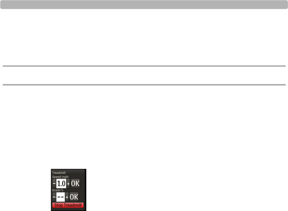
Preparing the Patient
ST80i Stress Test System Instructions for Use 3-35
Controlling the Treadmill or Ergometer
At any point during the stress test, you can switch to “Manual Mode” and change the speed
and elevation grade of the treadmill. This overrides the protocol settings for the current stage.
Once you enter manual mode, there is no next stage.
CAUTION Be sure to inform the patient of the changes.
If the treadmill is unavailable, ST80i displays “Unavailable” where the Start Treadmill
button would be.
To change the speed and elevation of the treadmill
1Place the pointer in the field that shows the current speed and click.
A box with a minus (-) sign to the left and a plus (+) sign to the right of the current setting
is displayed.
Figure 3-13 Treadmill Spped and Grade Adjustment
2Make the appropriate adjustment, down or up, and click OK.
3Place your pointer in the field that shows the current elevation and click.
A box with a minus (-) sign to the left and a plus (+) sign to the right of the current setting
is displayed.
4Make the appropriate adjustments, down or up, and click OK.
Figure 3-14 “Manual Mode” pop-up warning

The Patient Session
3-36 ST80i Stress Test System Instructions for Use
To stop the treadmill during the Exercise phase
Click the Stop Treadmill button.
The Treadmill stops.
Consult “Maintaining the ST80i System” on page 5-1 with regard to the inspection of cables
and attachments between the PC and the Treadmill.
Notifications and Alerts
ST80i provides visual indications or alerts in case of dramatic morphology or rhythm changes.
All notifications are preconfigured in the user profile. They include the fields to be displayed
or printed as well as specific audio alerts.
As part of the user profile, you can select to display and/or print the following Arrhythmia
fields:
Asystole [SRS 3.2.14.3.14]
Absolute Pause
1 missing beat
2 missing beats
Ventricular Fibrillation
VT
SVT
Premature Ventricular Contractions (PVC)
Extreme HR
Sudden drop in BP
Vrun(>=3PVs)
Vcouplet(2 PVCs)
Ventricular Bigeminy
Ventricular Escape Beats
Afib
The preconfigured audio alerts consist of the following:
NIBP
SpO2
Dose
Notifications
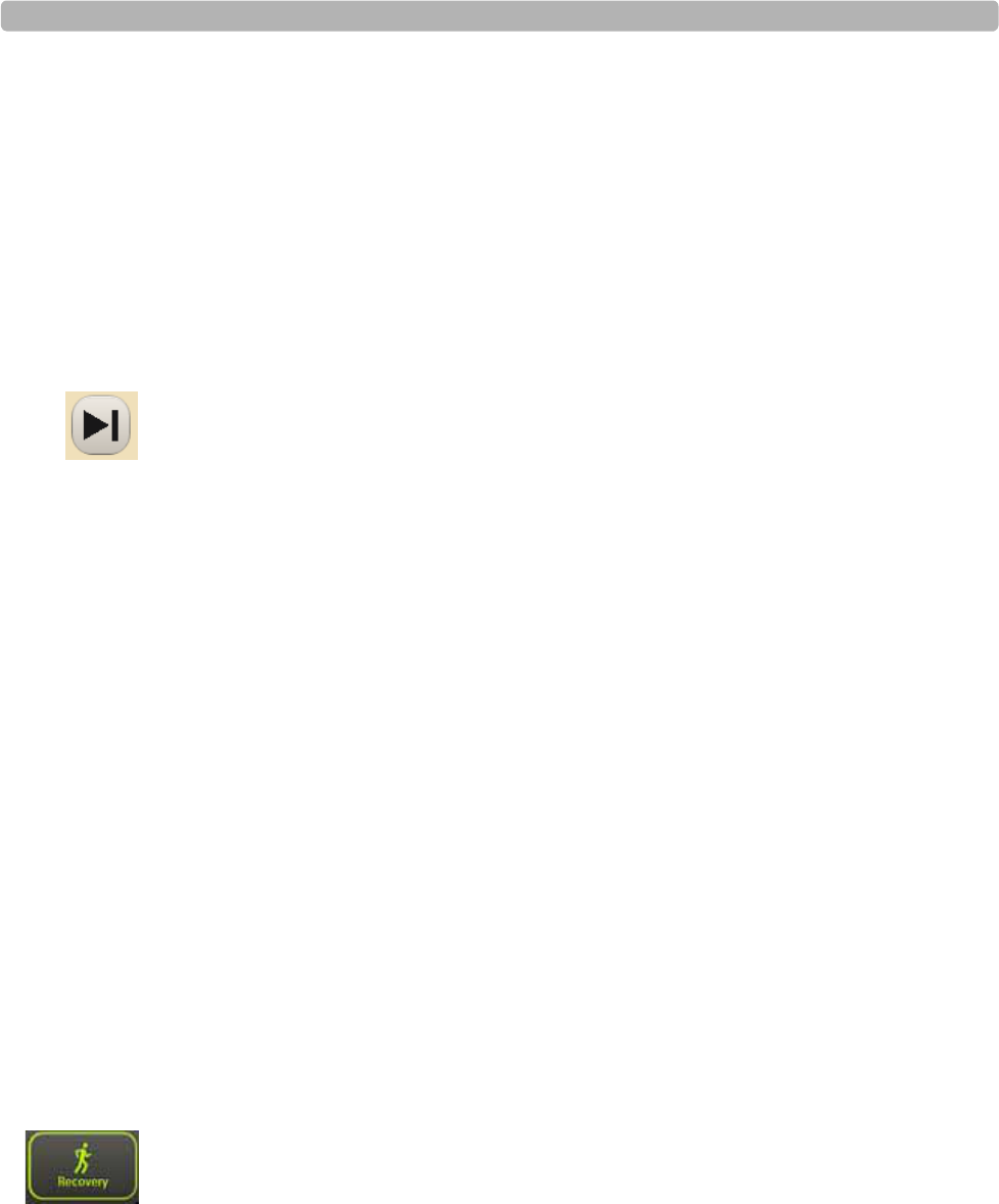
Preparing the Patient
ST80i Stress Test System Instructions for Use 3-37
Stage Change
See the ST80i Installation and Configuration Guide for more information regarding the setting
of notifications.
See also “Global Interpretive Settings” on page 3-40.
Ending the Exercise Phase
The protocol determines the number of exercise stages as well as their duration. Once the final
stage is complete, the application automatically moves into the Recovery phase.
During the final stage, you can end the exercise stress test and move directly to Recovery by
clicking the Advance button on the Procedure bar.
Generally, you terminate the Exercise phase when the patient reaches a percentage of their
target heart rate. The clinician determines the end point according to patient's status and many
patients never reach 100%. The target heart rate is pre-configured in the user profile.
If the reading reaches 100% of the target heart rate, the graph indicator color changes from
aqua to red.
Recovery Phase
When the last stage of the Exercise phase is complete, ST80i automatically moves into the
Recovery phase. The Recovery phase is preset under Exercise Protocols to run for 3 minutes at
a maximum speed of 1.5 mph with an elevation of 0%.
See the ST80i Installation and Configuration Guide for Exercise Protocol settings.
When the patient has completed the Exercise phase or the test has been discontinued (as
documented in “Reason to End” in the Summary), the exercise stress test enters the Recovery
phase.
To automatically enter the Recovery phase
If the last exercise stage of the protocol is completed, ST80i automatically enters the
Recovery phase.
To manually enter the Recovery phase
Click Recovery.
The system moves into the Recovery phase of the test.
You can now acquire a resting ECG and blood pressure and proceed with the Recovery phase
of the test.

The Patient Session
3-38 ST80i Stress Test System Instructions for Use
During the Recovery phase:
The system automatically prints a 12-lead ECG. The 12-lead ECG is printed at this stage
transition regardless of system settings.
The total exercise time clock freezes.
ST80i advances the treadmill or ergometer to the recovery workloads specified in the
protocol.
Select Stop Treadmill to stop the Treadmill. (You can also select the End button)
Using the Notes icon, you can enter comments describing why the patient ended the
Exercise phase of the test, the patient’s symptoms, and conclusions.
Figure 3-15 Recovery Phase Screen
To end the Recovery phase
1Click the Report button.
A message displays: “Confirm End of Study. The data will be saved.”
2Click OK. You also have the option to cancel.
The message “Loading” is displayed.
The Report screen is displayed.

Preparing the Patient
ST80i Stress Test System Instructions for Use 3-39
Report Phase
When you have determined that the patient has completed the Recovery phase of the stress
test, you can manually move to the Report phase where the Report screen is visible.
Data from the Recovery Phase is saved as part of the Final Stress Report. When you save the
stress test, the patient enters the Post-Recovery phase. This phase appears as part of the Report
phase in the Final Stress Report.
Post-Recovery
The Post-Recovery phase begins when the Recovery phase ends, and it stops when the
Report screen is opened. The Post-Recovery phase lasts from 5 to 60 minutes. During the
Post-Recovery phase, ST80i continues to monitor the ECG, arrhythmia alerts, as well as
sudden HR and BP changes. Data will not be saved unless an event is triggered. If events are
triggered, the event data is saved as part of the final report.
See “Notifications and Alerts” on page 3-36
NOTE ST80i will stop stream-test data after the 60-minute Post-Recovery phase. From the Report screen,
you can review and modify the content of the final test report. You can print the individual reports
that are also included in the final report, save the final report, and print it. After you save the report,
you can export it to a PDF file for distribution or storage.
Report Screen
On the Report screen, you can review and edit the stress test results to prepare the Final Stress
Report. The final report includes the Patient Information, Summary, Trends, Average QRS,
Resting ECG results, Events, and Tabular Report. The report is then confirmed, saved,
exported, archived, and/or printed on pre-configured printers. You have the option to print the
whole report or specify which page(s) to be printed.
From the Report screen, you can also review or replay the stress test and finalize (or confirm)
the final report before export.
See “Working with Reports” on page 4-1 for information on the Report Phase and Report
screen.

The Patient Session
3-40 ST80i Stress Test System Instructions for Use
Global Interpretive Settings
In the Settings section of the ST80i application, you can configure the Global Interpretive
Settings for DXL Algorithm and CALg templates, include the following:
DXL Algorithm
Adult Bradycardia
Borderline Statement Sensitivity
Pacer Detection
Report Confirmation Label
CALg Templates
Arrhythmia Analysis
ST Segment Analysis
J-ST Settings
Global Interpretive Settings also include:
Arrhythmia Event Notification
ST Amplitude Calculation
To configure the Global Interpretive Settings, see the ST80i Installation and Configuration
Guide.
Pace-Pulse Detection
The Pace-Pulse detection algorithm detects both atrial and ventricular pacing. Pacemaker
detection is preset in the user profile. The options include:
Paced
Paced (Magnet)
Non-Paced
Not Known if Paced
“Not known if paced” is the default mode, in which the detector uses its default sensitivity
setting to determine if pacemaker pulses are present.
The pace-pulse detection setting in effect at the time a snapshot is taken is used for the analysis
of that snapshot. If the pace-pulse program is enabled and it detects the presence of pace-
pulses, it will provide output in textual and graphical formats:
The interpretive report will contain textual statements about the findings for the pace-
pulse program.

Preparing the Patient
ST80i Stress Test System Instructions for Use 3-41
Tick marks appear on the waveform (both printed and displayed) at locations where pulses
are detected. The interpretive report contains textual statements about findings.
Only one set of tick marks will be printed for any given period of acquisition, regardless of
the number of channels presented.
The pace-pulse detection setting, in effect at the time a snapshot is taken, is used for the
analysis of that snapshot.
To configure Pace Detection, see the ST80i Installation and Configuration Guide.

The Patient Session
3-42 ST80i Stress Test System Instructions for Use
Printing During the Stress Test
At any time during the stress test, you can trigger real-time ECG (a real-time ECG is defined
as 10 seconds of ECG data) and continuous Rhythm printing using the icons displayed on the
Exercise screen. The time latency should be less than 7 seconds. You can also capture and
store events for later review and reporting. The events can be saved with notes and can be
printed with the context ECG data.
Arrhythmia events can trigger automatic printing with the context ECG, if configured. In
addition, you can also turn off the continuous printing both on the configuration and during the
test.
Printer Configuration
During the patient session, you have two print options:
ECG Print
Rhythm Print
Some print settings are preconfigured in advance while some can be changed during an
exercise stress test. The settings include:
Printer selection
Timing of Print
– ECG Print - by stage
– ECG manual - using the ECG Print button
– Rhythm Print manual - using the Rhythm Print button
Print layout
On the Config screen [System Settings System], you can preconfigure the printer for each
type of report:
Select ECG Report Printer:
–Off
– PDF Complete
– Microsoft XPS Document Writer
– Local Thermal Printer
Select Event Report Printer:
–Off
– PDF Complete
– Microsoft XPS Document Writer

Printing During the Stress Test
ST80i Stress Test System Instructions for Use 3-43
– Local Thermal Printer
Select Rhythm Report Printer:
–Off
– Local Thermal Printer
Select Final Report Printer:
–Off
– PDF Complete
– Microsoft XPS Document Writer
– Local Thermal Printer
On the Config screen [User Profile ECG Report], ECG Print is preconfigured with the
following:
ECG Layout
Speed (mm/sec)
Gain (Limb Leads)
Scale (Chest Leads)
On the Config screen, the timing of the ECG Print is configured on the Exercise Protocols tab.
The print interval options include:
Off
Begin
End
EveryLeads
You can also print an ECG at any time by clicking the 12 Leads Print button.
On the Config screen [User Profile Rhythm Report], you can configure Rhythm Print
settings for the Rhythm Report. They include:
ECG Layout - select Leads
Rhythm Settings
– Speed mm/sec - 5, 10, 25, 50
– Gain (Limb Leads) - 2.5, 5, 10, 20
– Scale (Chest Leads) - Full, Half
During the patient session, you can change the Rhythm Print settings using the Gear (Quick
Settings) icon. See “Using the Toolbar Icons” on page 2-15 for an explanation.
The Patient Session
3-44 ST80i Stress Test System Instructions for Use
Print Options
ST80i supports several print options during the stress test, including:
Real-time ECG
Resting 12-Lead ECG report (with interpretation) – interpretion is printed only during Pre
Exercise phase when an event is selected
Stage printout (without interpretation)
Event printout (without interpretation)
Real-time rhythm printing
Real-Time ECG
Any time during the testing, you can print a real-time 12-Lead ECG from the Exercise screen.
You can trigger a real-time ECG using the 12 Lead Print button on the screen. The time
latency should be less than 7 seconds.
To print a real-time ECG
Click the 12 Lead Print button on the Procedure bar.
12-Lead Resting ECG Report
Before the formal stress testing starts, or after the stress testing completes, you can print a
12-Lead resting ECG report.
The 12-Lead Resting ECG is printed according to the user profile settings. Resting ECG
measurement and interpretation is included as part of a 12-Lead ECG Report.
Report Title
Patient Demographic
Study Information
Interpretation of 12-Lead ECG statement
12x1, 6x2, 3x4, 3x4 3R display
To print a 12-Lead Resting ECG Report
Click the 12 Leads Print button on the Procedure bar.
For more information on printing reports, see “Working with Reports” on page 4-1.

Printing During the Stress Test
ST80i Stress Test System Instructions for Use 3-45
Stage Printout and Event Printout
Stage printout and Event printout are 12-Lead ECG reports without any measurement or
interpretation during the stress testing. Stage printout is configured in the Protocol. Event
printout is printed if the printer type is configured.
The Stage printout is automatically generated if preconfigured. It prints out an average
report of the stage, which shows the average beat maximum ST changes in this stage as
well as the current ST change. This is defined for each stage of the exercise protocol when
an ECG is automatically generated for the stage.
The Event printout is triggered when you document patient symptoms using the Event
icon.
– Event symptoms include: Supine, Chest Pain, Shortness of Breath, Mason-Likar,
Standing, and Hyperventilation.
– You can also document a new event using this icon.
NOTE If enabled, Arrhythmia events can trigger automatic printing with the context ECG – which are
configurable to the user.
See the ST80i Installation and Configuration Guide for how to enable Arrhythmia events.
At the end of each stage, ST80i automatically prints an average report of this stage. This report
shows the average beat, maximum ST changes in this stage, as well as the current ST change.
You can also print at any time during the test from the Exercise screen to capture and store
events or snapshots for later review and reporting. The followingevents and snapshots can be
saved with notes:
Hyperventilation
Chest Pain
Shortness of Breath
User-defined urgent case
To record and print an Event, see “Recording an Event” on page 2-25.
The Stage/Event printout includes the following:
Report title
Protocol name, phase, stage number, etc.
Patient demographic
Heart rate, blood pressure, MPH, etc.
ECG Waveform
Average beat
Event name (for Event printout only)
The Patient Session
3-46 ST80i Stress Test System Instructions for Use
Maximum ST changes in this stage (for Stage printout only)
Current ST change (for Stage printout only)
Continuous Rhythm Strip
You can trigger continuous rhythm printing using the Rhythm Print button on the Exercise
screen. You can also turn off continuous printing by using the same Rhythm Print button.
Before using the Rhythm Print option, you can:
ST80i software automatically advances the paper to the page header
You can adjust Rhythm Print settings using the Gear (Quick Settings) icon
To print a continuous Rhythm Strip
1Click the Gear (Quick Settings) icon; select the Rhythm Print tab.
2Adjust the settings, if applicable, for:
– Leads (Select the leads you want to print)
– Limb Gain (options include: 2.5 mm/mV, 5 mm/mV, 10 mm/mV, 20 mm/mV)
– Chest Gain (options include Full, Half)
– Speed (options include 5 mm/s, 10 mm/s, 25 mm/s, 50 mm/s)
3Click the Rhythm Print icon
4To end the printing, click the Rhythm Print icon again.
De-Identification
When printing patient reports, you can de-identify the study to be in HIPAA compliance. This
option hides all patient identification information from the study printout so that the identity of
the patient is protected.
This option is preconfigured in the Settings section of the application.
To de-identify a patient
1Click Settings on the Main Screen.
2Select the System Settings tab
3Select the System option
4Place a checkmark in the “De-identify Patient Information on Report” box
5Click Save.
Proceed to “Ending the Patient Session,” which follows.

Ending the Patient Session
ST80i Stress Test System Instructions for Use 3-47
Ending the Patient Session
After saving the Final Stress Report, you are ready to close out the patient session.
The patient can now be disconnected from the PIM:
Detach patient from PIM.
Detach electrodes.
For details about working with the final report, including viewing, editing, printing, and
saving reports, see “Working with Reports” on page 4-1.
Starting a New Patient Session
You do not have to exit the application to start a new session, unless you want to use a
different user profile. Otherwise, you exit the application only when you are shutting down the
system.
Once the data from the previous patient session has been saved, you can begin a new
patient session. All user profile settings will return to the same as the previous test unless
the application is exited and a different user logs in. Some of the settings changed using the
Gear (Quick Settings) icon also remain in effect.
NOTE All patient information and stress study data of the previous patient is cleared automatically when a
new patient session starts.
To start a new patient session
1Select Main.
2Select Worklist.
3Select the patient’s name.
Exiting the Application
You exit the application when need to use a different profile, when a new user is logging onto
the system, or when you are shutting down the system.
To exit the ST80i application
Click the “X” in the upper right corner of the Main screen.

The Patient Session
3-48 ST80i Stress Test System Instructions for Use

4
4-1
1Working with Reports
Overview
When you enter the Report phase, data from all phases of the test are saved as part of the final
stress report that is viewed on the Report screen.
From the Report screen, you can review and modify the contents of the Final Stress Report,
which is displayed in tab format. This includes report summary information, trends, average
QRS, events and resting ECG. You can save the final report, and then print it. In addition, you
can print the individual reports that are part of the final report. After you save the report, you
can export it as a PDF file for distribution or storage.
This chapter provides the following information:
Overview . . . . . . . . . . . . . . . . . . . . . . . . . . . . . . . . . . . . . . . . . . . . . . . . . . . . . .4-1
Report Phase . . . . . . . . . . . . . . . . . . . . . . . . . . . . . . . . . . . . . . . . . . . . . . . . . . .4-3
Post-Recovery Phase. . . . . . . . . . . . . . . . . . . . . . . . . . . . . . . . . . . . . . . . . .4-3
Report Screen . . . . . . . . . . . . . . . . . . . . . . . . . . . . . . . . . . . . . . . . . . . . . . . . . .4-4
Title Bar . . . . . . . . . . . . . . . . . . . . . . . . . . . . . . . . . . . . . . . . . . . . . . . . . . .4-6
Procedure Bar . . . . . . . . . . . . . . . . . . . . . . . . . . . . . . . . . . . . . . . . . . . . . . .4-7
Change (J+) Point. . . . . . . . . . . . . . . . . . . . . . . . . . . . . . . . . . . . . . . . .4-7
Save . . . . . . . . . . . . . . . . . . . . . . . . . . . . . . . . . . . . . . . . . . . . . . . . . . .4-7
Export . . . . . . . . . . . . . . . . . . . . . . . . . . . . . . . . . . . . . . . . . . . . . . . . .4-8
Print . . . . . . . . . . . . . . . . . . . . . . . . . . . . . . . . . . . . . . . . . . . . . . . . . . .4-9
Confirm . . . . . . . . . . . . . . . . . . . . . . . . . . . . . . . . . . . . . . . . . . . . . . . .4-9
Replay. . . . . . . . . . . . . . . . . . . . . . . . . . . . . . . . . . . . . . . . . . . . . . . . .4-10
Real-Time ECG for One Lead . . . . . . . . . . . . . . . . . . . . . . . . . . . . . . . . .4-12
Print Options . . . . . . . . . . . . . . . . . . . . . . . . . . . . . . . . . . . . . . . . . . .4-12
Current Blood Pressure . . . . . . . . . . . . . . . . . . . . . . . . . . . . . . . . . . .4-12
Final Stress Report Overview . . . . . . . . . . . . . . . . . . . . . . . . . . . . . . . . . . . . .4-13
Report Screen Tabs . . . . . . . . . . . . . . . . . . . . . . . . . . . . . . . . . . . . . . . . . . . . .4-15
Summary Report. . . . . . . . . . . . . . . . . . . . . . . . . . . . . . . . . . . . . . . . . . . .4-15
Tabular Report . . . . . . . . . . . . . . . . . . . . . . . . . . . . . . . . . . . . . . . . . . . . .4-17
Trend Graph Report . . . . . . . . . . . . . . . . . . . . . . . . . . . . . . . . . . . . . . . . .4-18
Averages Report . . . . . . . . . . . . . . . . . . . . . . . . . . . . . . . . . . . . . . . . . . . .4-19
Events Report . . . . . . . . . . . . . . . . . . . . . . . . . . . . . . . . . . . . . . . . . . . . . .4-20
Resting ECG Report . . . . . . . . . . . . . . . . . . . . . . . . . . . . . . . . . . . . . . . . .4-23
Full Disclose Report . . . . . . . . . . . . . . . . . . . . . . . . . . . . . . . . . . . . . . . . .4-24
Saving the Final Stress Report . . . . . . . . . . . . . . . . . . . . . . . . . . . . . . . . . . . .4-24

Working with Reports
4-2 ST80i Stress Test System Instructions for Use
Printing Reports. . . . . . . . . . . . . . . . . . . . . . . . . . . . . . . . . . . . . . . . . . . . . . . .4-26
Printer Configuration . . . . . . . . . . . . . . . . . . . . . . . . . . . . . . . . . . . . . . . .4-26
Print Report Settings. . . . . . . . . . . . . . . . . . . . . . . . . . . . . . . . . . . . . . . . .4-28
ECG Report . . . . . . . . . . . . . . . . . . . . . . . . . . . . . . . . . . . . . . . . . . . .4-29
Events Report. . . . . . . . . . . . . . . . . . . . . . . . . . . . . . . . . . . . . . . . . . .4-30
Rhythm Report. . . . . . . . . . . . . . . . . . . . . . . . . . . . . . . . . . . . . . . . . .4-31
Final Report . . . . . . . . . . . . . . . . . . . . . . . . . . . . . . . . . . . . . . . . . . . .4-32
Print (Quick Print Settings) Button . . . . . . . . . . . . . . . . . . . . . . . . . . . . .4-33
Printing the Final Report . . . . . . . . . . . . . . . . . . . . . . . . . . . . . . . . . . . . .4-34
Printing Individual Reports. . . . . . . . . . . . . . . . . . . . . . . . . . . . . . . . . . . .4-35
Post-Recovery ECG Printing . . . . . . . . . . . . . . . . . . . . . . . . . . . . . . . . . .4-37
De-Identify the Report . . . . . . . . . . . . . . . . . . . . . . . . . . . . . . . . . . . . . . .4-37
Working with Archived Reports . . . . . . . . . . . . . . . . . . . . . . . . . . . . . . . . . . .4-38
Report (Stress Study) Database . . . . . . . . . . . . . . . . . . . . . . . . . . . . . . . .4-38
Database Configuration . . . . . . . . . . . . . . . . . . . . . . . . . . . . . . . . . . .4-39
Patient Reports . . . . . . . . . . . . . . . . . . . . . . . . . . . . . . . . . . . . . . . . . . . . .4-40
Search for Reports . . . . . . . . . . . . . . . . . . . . . . . . . . . . . . . . . . . . . . .4-42
Confirm a Report . . . . . . . . . . . . . . . . . . . . . . . . . . . . . . . . . . . . . . . .4-42
Transfer Reports. . . . . . . . . . . . . . . . . . . . . . . . . . . . . . . . . . . . . . . . .4-42
Delete Reports . . . . . . . . . . . . . . . . . . . . . . . . . . . . . . . . . . . . . . . . . .4-43
Backup Reports . . . . . . . . . . . . . . . . . . . . . . . . . . . . . . . . . . . . . . . . .4-44
Restore Reports . . . . . . . . . . . . . . . . . . . . . . . . . . . . . . . . . . . . . . . . .4-44
View a Report. . . . . . . . . . . . . . . . . . . . . . . . . . . . . . . . . . . . . . . . . . .4-45
Replay a Report . . . . . . . . . . . . . . . . . . . . . . . . . . . . . . . . . . . . . . . . .4-45
Viewing Reports Saved as PDF Files. . . . . . . . . . . . . . . . . . . . . . . . . . . .4-45
Exporting Reports (Export Exam) . . . . . . . . . . . . . . . . . . . . . . . . . . . . . . . . .4-46
External Storage of Stress Study data. . . . . . . . . . . . . . . . . . . . . . . . . . . .4-46
ECG Export (Transfer?) Destination Sites . . . . . . . . . . . . . . . . . . . . . . . .4-47
Exporting Reports to an ECG Management System . . . . . . . . . . . . . . . .4-48
File Naming Conventions . . . . . . . . . . . . . . . . . . . . . . . . . . . . . . . . .4-48
Importing Reports . . . . . . . . . . . . . . . . . . . . . . . . . . . . . . . . . . . . . . . . . . . . . .4-50
Download Pdfs from a TraceMasterVue Remote Site . . . . . . . . . . . . . . .4-50
Import Data From a Synapse Remote Site . . . . . . . . . . . . . . . . . . . . . . . .4-51

Report Phase
ST80i Stress Test System Instructions for Use 4-3
Report Phase
When stress testing enters the Report phase, you can edit the report with the algorithm output
to generate a Final Stress Report. The final report is divided into several pages that include, for
example, the report summary, trends, average QRS, events, and resting ECG.
During the Report phase:
ST80i freezes the Recovery display while the test information is transferred to system
storage.
ST80i loads the Report screen, so you can specify the parameters and format of the final
report.
A real-time 7.5-second ECG is displayed in the lower-left section of the screen for the
Post-Recovery phase
Post-Recovery Phase
A Post-Recovery phase lasts from 5 to 60 minutes. During the Post-Recovery phase, ST80i
will continue to monitor the ECG, arrhythmia alerts, as well as sudden HR changes. Data will
not be saved unless an event is triggered. If events are triggered, the event data is saved as part
of the Final Stress Report.
NOTE ST80i will stop streaming test data after the 60-minutes Post-Recovery phase.

Working with Reports
4-4 ST80i Stress Test System Instructions for Use
Report Screen
During the Report phase of the test, you work from the Report screen to review, update, and
save the data for the Final Stress Report, which you can then save, confirm, export, archive
and/or print on pre-configured printers. You have the option to print the whole report or
specify which individual reports to print and to change default printer settings.
From the Report screen, you can also review or replay the exercise stress test and finalize (or
confirm) the final report before export.
As you prepare the final report on the Report screen, you can do the following:
Review the ECG and make any adjustments to the waveforms (for example, to the J-point,
if needed)
Add or update patient information
Print the individual ECGs and delete extraneous ECGs
Review and edit final test data
Review events
Review the exam
Prepare the patient’s final stress report
Save the report and export it, if appropriate
Archive the patient’s stress report
The Archive screen is used to store the exercise stress test results. All reports and test records
are stored in ST80i and are exported to servers based on settings.
Changes made to the Final Stress Report through ECGVue are saved into the database where
the ECGVue is connected.
NOTE The Final Stress Report is also stored in the stress system’s Report database, which you can access on
the Main screen. When you click the Report button, the “Select Archive from List” screen is
displayed. Each report is labeled according to its status:
Complete: all required fields are filled
Incomplete: any required field is not filled
Confirmed/Signed
Exported
For more information regarding archived reports, see “Working with Archived Reports” on
page 4-36.
Report Screen
ST80i Stress Test System Instructions for Use 4-5
Figure 4-1 ST80i Report Screen
Table 4-1 ST80i Report Screen Features
Feature Description
ATitle Bar - where you enter or update patient information in the Patient
Demographics window.
BProcedure Bar - [Report, Status: Complete or Incomplete] and buttons:
Change J+ , Save, Export, Print, Confirm, Replay
CReport Tabs Summary, Tabular, Trend Graph, Averages, Events, Resting ECG,
Full Disclose
DReal-time 7.5-second ECG by selected lead (ECG for one lead is displayed in
the lower left section of the screen; use the Change Lead drop-down arrow to
change selected lead)
ETwo print options for the current ECG lead: Print 12-Lead ECG Report;
Start Rhythm Printing
FCurrent Blood Pressure – shows current blood pressure of the patient
A
B
C
D
EF

Working with Reports
4-6 ST80i Stress Test System Instructions for Use
Title Bar
From the Report screen, you can enter or update information about the patient before or during
the test. If you did not fill in or update this information during the Exercise phase, you can
open the Patient Demographics screen to update this information as necessary. For an
explanation of the features of the title bar, see “Title Bar” on page 2-7.
When you click the patient’s name on the Title Bar, you can update or amend the following
information:
Patient Information
History
Medications/Dosage
Physician/Order
Custom Fields
To add or update patient information
1Click on the Patient Name in the Report screen title bar.
The system displays the Patient Demographics window.
2Enter new information for the patient or update the fields as needed.
For details on the fields in the window, see “Patient Information Management” on
page 3-5.
3Click OK when finished to save the data.
If you manually update patient information, including Notes and Symptoms during the test or
on the Report screen, this information is updated in the archived report in the Report stress
system database.
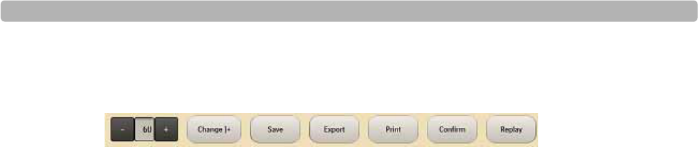
Report Screen
ST80i Stress Test System Instructions for Use 4-7
Procedure Bar
Figure 4-2 Procedure Bar
On the Procedure bar, you can:
Adjust the J+ Point
Save the report
Export the report
Print the report
Confirm the report
Replay the ECG
Change (J+) Point
The ST Measurement (J+) Point is preconfigured in the user profile.
[Settings User Profile: Algorithm J-ST (msec)]
You can adjust the J+ Point value on the Report screen to re-analyze the stress test using a
different measurement point. Once the J+ms value is modified, ST80i recalculates all related
values and updates the corresponding displays on the Report screen.
NOTE The new ST value does not automatically replace the old one until the report is saved.
To modify the ST measurement point
On the Procedure bar, click the plus (+) or minus (-) to change the value in milliseconds
for J-ST.
To recalculate all the ST values based on the new J+ setting
Click the Change J+ button.
Save
Use this button to save the report to the stress system database after you have finished
updating and reviewing the report data.
When a Final Stress Report is saved, it may then be exported to the central server. The report
can be finalized and signed on both device side and server side. The stress study raw data will
be saved in the local stress study database. The export status and date/time of last export are
also maintained.

Working with Reports
4-8 ST80i Stress Test System Instructions for Use
It is also possible to export a report [directly to external media such as a USB flash stick in
PDF format. The Final Stress Report may also be exported in PDF format which can be
reviewed on any PC. The Final Stress Report in PDF format can then be emailed to referring
physician. See also “Exporting Reports (Export Exam)” on page 4-44.
Export
You can export your reports to Remote Sites that have been preconfigured in the Settings
section of the application.
If you have not configured Remote Sites, you will get the following error message: “Error. No
default remote site is set. Please set default remote site in System Settings!”
To create Remote Sites, see the ST80i Installation and Configuration Guide.
See also the section regarding the export of archived reports entitled “Exporting Reports
(Export Exam)” on page 4-44.
To export a report using the Export button -- procedure in development--

Report Screen
ST80i Stress Test System Instructions for Use 4-9
Print
You can use the Procedure bar’s Print button to print individual reports or the Final Stress
Report.
Before printing individual reports, you need to select a printer type. When using a laser
printer, the grid can be set to print a grid on standard paper. Individual reports can be printed
both before and after you save the report.
The type of individual reports that can be printed include:
Patient ID
Summary
Trend Graphs
Average QRS
12-Lead Resting ECGs
Rhythm Events
When printing a Final Stress Report, you can choose which individual reports to include and
the number of copies to print for each individual report. You can also print a complete Final
Stress Report. Regardless of settings, a summary report will always be printed on the first page
of a Final Stress Report.
See the section entitled “De-Identify the Report” on page 4-35 regarding how to print
individual reports as well as the Final Stress Report.
Confirm
Once you review and edit the results, you can then confirm the report before exporting. You
will, however, need the appropriate permission level to export the report.
In the Select Archive from List window, the test status is listed as follows:
Complete: all required fields are filled
Incomplete: any required field is not filled
Confirmed/Signed
Exported
NOTE A stress study report cannot be confirmed or exported to TMVue if the required patient fields are not
complete.

Working with Reports
4-10 ST80i Stress Test System Instructions for Use
For more information regarding patient fields, see the section entitled “Patient Information
Management” on page 3-5.
When you click the Confirm button, a dialog box is displayed.
Figure 4-3
To confirm the report
1Enter your User ID.
2Enter your password.
3Click OK.
Replay
When you click the Replay button on the Report screen, you can review the real-time ECG
waveforms. This button provides you with the ability to review a back-completed stress report
that is either finalized or non-finalized.
You can also print a 12-Lead ECG or print a rhythm strip during the review of the study. This
feature is beneficial if you wish to review a specific segment of the test. When reviewing a
test, you can:
Change the ECG waveform speed from real-time speed to four times faster or slower
Pause the ECG stream
Print or reprint a 12-lead ECG or rhythm strip for significant episodes
Move the trend cursor to any location to skip forward or back in time
To replay the exercise stress test
1Click the Replay button on the Procedure bar.
This brings you to ECG results that were recorded at the start of the Exercise phase. You
can then view the exercise stress test by using the “floating status bar” that appears at the
bottom of the ECG. This bar may be hidden.
2To view the bar, sweep your pointer over image.
A gray circle moves across the status bar (blue). As it moves, the time is displayed to the
right showing both current and end time.

Report Screen
ST80i Stress Test System Instructions for Use 4-11
Figure 4-4
Figure 4-5
3To hide the bar, sweep your pointer over the image.
At any time during the Replay of the exercise stress test, you can print an ECG or Rhythm
Strip.
Click the ECG button for a 12-Lead ECG.
Click the Rhythm Print button for a rhythm strip.
Once you have replayed the ECG, you can return to the Report screen.
To return to the Report phase screen -- procedure in development--
NOTE Once the patient session is over, you can also review a patient test, after you have saved the results,
by going to the Main screen. Click the Report button to open the Select Archive from List screen.
See the section entitled “Working with Archived Reports” on page 4-36.

Working with Reports
4-12 ST80i Stress Test System Instructions for Use
Real-Time ECG for One Lead
On the bottom of the Report screen, patient data is still captured for one lead. You can change
the lead by using the drop-down menu to the right.
Figure 4-6
Print Options
On the bottom of the screen, to the right of the real-time ECG, are two print options for the
current lead in view:
Print 12-Lead ECG Report
Start Rhythm Printing
When you click the Print 12-Lead ECG Report button, you will get a printout of that segment
of the ECG.
When you click the Start Rhythm Printing button, a rhythm strip begins printing. To turn off
Rhythm Printing, click this button again.
Current Heart Rate
The current heart rateof the patient is displayed on the bottom right section of the screen.

Final Stress Report Overview
ST80i Stress Test System Instructions for Use 4-13
Final Stress Report Overview
The Final Stress Report is based on data gathering during the 5 phases of an exercise stress
test. They include:
Pre Exercise Phase
Exercise Phase
Recovery (and Post-Recovery) Phase
Report Phase
The Final Stress Report includes the patient information summary, trends, average QRS,
resting ECG results and events. ST80i allows you to choose several individual reports to
include in the Final Stress Report.
The composition of a stress report may or may not include the following:
Patient ID Report
Summary Report
Trends Report
Average QRS Report
12-Lead ECG Report
Rhythm Events Report
ST Analysis
Interpretation
Measurements
After finishing the data acquisition, stress testing enters the report-generating phase. Once
signed by a cardiologist or clinician, the report is finalized.
After a stress test procedure, you work from the Report screen to review, update, and save the
data for the Final Stress Report. When the report is satisfactory, you can print the individual
reports on a laser printer or directly to a thermal printer when printing from ST80i.
Data from the Recovery phase is included as part of the final report. In the Post-Recovery
phase, the data will not be saved unless an event is triggered. If so, only the event data is saved
as part of the final report.
WARNING ECG signals printed on a laser report should not be used to make time-sensitive measurements
directly from the printed page.
NOTE The Final Stress Report cannot be saved without patient demographics.

Working with Reports
4-14 ST80i Stress Test System Instructions for Use
A Final Stress Report includes the following:
Patient ID
Summary
Tabular Summary
Trends Graph
Average Beat Complexes
Rhythm Events
12-Lead Interpretative Resting ECG Report
Each report is configured to print or not to print in a Final Stress Report except thePatient ID
Report, which is the minimum printed page in a Final Stress Report. It is printed as the first
page of the Final Stress Report.
You can configure which reports are included in the Final Stress Report. This setting can be
changed from the Report screen.
Patient ID Report
Summary Report
Trends Report
Average QRS Report
Rhythm Events Report
12-Lead ECG Report
You can reprint each report manually. You can also specify the number of final report copies
to print. In addition, you can specify the printer to send the final report copies and whether or
not to have the grid visible.
CAUTION If you input incorrect NIBP data, it can cause errors for NIBP-related parameters in reports.

Report Screen Tabs
ST80i Stress Test System Instructions for Use 4-15
Report Screen Tabs
The sections of the final report are displayed as tabs on the Report screen. The tabs contain the
patient's ECG data in a variety of formats:
Summary
Tabular
Trend Graphs
Averages
Events
Resting ECG
Full Disclosure
Figure 4-7 Report Screen
The following sections describe each report tab:
Summary Report
The Summary Report includes:
Report title and patient demographics
Study information including, for example, study date and time, test type, protocol,
referring physician, attending physician, and technician
Clinical information including, for example, the reason for the test and the reason to end
test, PVCs, Risk scores, test summary for all phases, free-text entry of narrative summary
notes, and signatures

Working with Reports
4-16 ST80i Stress Test System Instructions for Use
On this screen, the gender specific parameters, measurements and risk scores that are
displayed can be printed. In addition, you can override the algorithm and select Max ST
deviation for the risk-score calculation. When you change the parameters, they appear in dark
red and italic.
NOTE The Summary Report cannot be printed without patient demographics.
On the Summary tab of the Report screen, you can include your comments about the test, along
with the Reason to End and Symptoms. All values included are based on data captured during
each stage of the exercise stress test. The screen is divided into four sections:
Summary – The Summary region shows total exercise time, maximum treadmill speed,
and maximum grade or watts (for Ergometers), as well as leads displaying greater than
100 microvolts of ST change. Duke and FAI score also appear, if applicable. FAI %
statistics only appears for the Bruce protocol.
Max Values – Max values are presented as HR and time-achieved percentage of target HR
achieved, and maximum METS obtained as well as Double Product and maximum
systolic BP/maximum diastolic BP.
Max ST – Maximum ST measurements, based on J+60ms, are presented with elevation,
depression, total change, and ST/HR Index.
Comments – In the Comments section, you can:
– Update the Comment fields:
– Narrative
– Technician
– Reviewing Physician
– Reason for End – Update the Reason for End using the up and down arrows, as
well as the Del and Add buttons.
The ComboBoxItem 1 below Reason for End is used for X.
– Symptoms – Update the Symptoms using the up and down arrows, as well as the
Del and Add buttons.
The ComboBoxItem 1 below Symptoms is used for Y.
The Summary Report includes the following information on page 1:
Summary data displayed on the Report screen:
– Total exercise time
– Maximum treadmill (or ergometer) speed and grade achieved during test
– Max grade
– ECG leads that presented more than 100 uV (or 1 mm) of ST elevation or depression
during test
– Functional Aerobic Impairment (FAI%). Only for Bruce protocol
–PVCs

Report Screen Tabs
ST80i Stress Test System Instructions for Use 4-17
– Duke Score (treadmill only)
Max Values data displayed on the Report screen:
– Maximum heart rate
– Percentage of target heart rate attained
– Estimated maximum metabolic equivalents (METS)
– Double Product (Sys HR * BP)
– Maximum systolic and diastolic blood pressure
NOTE These values are not necessarily taken from the same blood pressure reading. They are simply the
highest measurements recorded of each of these values at any time during the test.
Max ST data displayed on the Report screen:
– Absolute ST Elevation and ST Depression times and leads
– Amount of ST Elevation and ST Depression change
– ST/HR Index
NOTE Patients may already have ST elevation or depression before exercise begins. It is important for the
clinician to see how much change occurs during exercise.
To print the Summary Report -- procedure in development--
Tabular Report
The Tabular Report includes:
Report title and patient demographic data
Study information including study date and time, ST measurement, test type, protocol,
referring physician, attending physician, and technician
Table items configurable per stage, phase name, stage name, relevant stress-related data,
and a time stamp of events
The Tabular tab displays the following tabular data by Exercise stage or by minute:
Time
Speed
Grade
HR

Working with Reports
4-18 ST80i Stress Test System Instructions for Use
BP
METS
HR*BP (Double Product)
12 Leads
Figure 4-8 Tabular Data Displayed by Stage
To print the Tabular Report -- procedure in development--
Trend Graph Report
The Trend Graph Report includes the following:
Report title and patient demographic data
Study information including data and time, test type, and protocol
4-Graph Trends (measurements vs. minutes)
ST Level Trends (mms vs. minute)
Test protocol
The following graphs are displayed:
Heart Rate
Blood Pressure (Systolic and Diastolic)
Speed/Grade of the Treadmill (or data from the Ergometer)

Report Screen Tabs
ST80i Stress Test System Instructions for Use 4-19
METS/Double Product (HR*BP)
Trends by lead for ST Level and ST Slope (use the right and left arrows to scroll)
To review the leads to the right, use the scroll bar.
Figure 4-9 Trend Graphs
To print the Trends Report -- procedure in development--
Averages Report
The Average Beat Complexes Report is an overview of median morphologies by stage or by
minute that are configurable at pre- and/or post-test stages.
This report includes:
Report title and patient demographic data
Study information
Default median morphologies for 12-lead at baseline, Max ST Depression, Peak Exercise
and End Test
User-defined median morphologies for 3, 6, and 12 leads at user-defined intervals as well
as ST Level and ST Slope for each lead
You can use the Print (Quick Print Settings) button to print the report by stage or by minute.

Working with Reports
4-20 ST80i Stress Test System Instructions for Use
Events Report
You can review Rhythm Events at any time after you enter the Report screen by clicking the
Events tab. You can also delete events that you do not want to include in the Final Stress
Report, and re-label events more appropriately.
The Rhythm Events Report includes prints of snapshots of all events, captured arrhythmias,
and RPE scale selections acquired during the Stress test. In addition, an Event Report is
configured to print each time during the exercise stress test if a specific event (e.g. Shortness
of Breath, Chest Pain, etc) was selected from the drop-down menu using the Event icon.
12-Lead ECGs that are printed during the Exercise and Recovery phases are included with the
Rhythm Events Report.
The Rhythm Events Report includes:
Report Title
Protocol Information
Patient Demographic Data
Heart Rate, Blood Pressure, MPH, etc.
ECG Waveform
Average Beat
Event Name (for Event printout only)
Figure 4-10 Events Tab
On this tab, you can:
Review Rhythm Events for all captured events (e.g. Chest Pain, Hyper Ventilation,
Shortness of Breath, Ventricular Tachycardia, Bigeminy, Trigeminy, etc.), arrhythmias,
and RPE scale selections acquired during the entire stress test.
Review 12-Lead ECGs printed during the Exercise and Recovery phases that are included

Report Screen Tabs
ST80i Stress Test System Instructions for Use 4-21
with the Rhythm Events.
Print and delete Rhythm Events as well as re-label them, as appropriate. Use the Print
(Quick Print Settings) button to print the events.
You can also review all the events captured during the test. In addition, you can also create
new events during the review. The newly captured events are added to the final report and then
saved back to the database.
To review Rhythm Events
1Click the Events tab.
The Rhythm Events window appears, displaying up to six events. Use the right and left
arrows to scroll.
2To select an Event, click anywhere in the Event snapshot to highlight it.
3Review the Event. You can perform any of the following actions:
– Click Print on the Procedure bar screen to print the Event.
– Click ReLabel to re-label an event.
– Click the “X” in the upper right corner of each Event to delete the Event. The word
Deleted appears across the Event in red. All deleted events are removed from the list.
– Click OK when finished to save your changes.
To re-label Events -- procedure in development--
1Click the Events tab.
The Rhythm Events window displays up to six events. Use the right and left arrows to
scroll.
2To select an Event to re-label, click anywhere in the Event snapshot to highlight it.
To delete Events -- procedure in development--
1Click the Events tab.
The Rhythm Events window displays up to six events. Use the right and left arrows to
scroll.
2To select an Event to delete, click anywhere in the Event snapshot to highlight it.
To print Events -- procedure in development--
1Click the Events tab.
The Rhythm Events window displays up to six events. Use the right and left arrows to
scroll.

Working with Reports
4-22 ST80i Stress Test System Instructions for Use
2To select an Event, click anywhere in the Event snapshot to highlight it.
IMPORTANT! Rhythm change notifications are provided when specific rhythm changes are detected; however, it is
the responsibility of the trained healthcare professional to determine the type of rhythm change and
appropriate action.
Additionally, the healthcare professional should not assume that all rhythm changes will be detected
and they are responsible for taking action when rhythm changes are observed on the displayed
waveforms and system fails to provide a notification. It is expected that only properly trained health
care professionals working directly under the supervision of a qualified physician will be operating the
ST80i Stress Test System during testing.
Resting ECG Report
Resting ECG measurement and interpretation are included as part of a 12-Lead ECG Report.
The 12-Lead ECG is printed according to the user profile settings. A Resting ECG is printed at
the beginning of each exercise stress test and is then printed in the Final Stress Report.
The Resting ECG tab shows a report of the resting ECG. At the top part of the report, patient
data as well as ECG data appears with interpretation. Before the formal stress testing starts, or
after the stress testing is complete, you can print a 12-Lead Resting ECG report.
The waveform area captures the ECG during the resting or supine stage during the Pre-
Exercise phase. The report is labeled “Supine” or “Mason-Likar.”
The report includes:
Patient Demographic Data
Study Information
Interpretation of 12-Lead ECG Report
12x1, 6x2, 3x4, 3x4 3R display
CAUTION Specific patient data is required for each interpretation. If entered data are found to be incorrect, the
ECG file may be edited and a new display/report can be printed.
You can configure mandatory patient information fields in system configuration. When these
mandatory fields are missing, you will be warned with a pop-up message box. If these fields
are changed, a warning message pops up and the resting ECG will be re-interpreted.
On this screen, you can scroll through the images on the screen using the right and left arrows.
You can also print a Resting ECG using the Print button on the Resting ECG screen.

Saving the Final Stress Report
ST80i Stress Test System Instructions for Use 4-23
Full Disclose Report
On this screen, the entire ECG waveform results of the stored stress tests are loaded for full
disclosure review.
To view an ECG for the whole exam or a moment in time, use the start feature at the bottom of
the screen.
The start time is noted in the bottom right corner of the waveform screen.
To print the Full Disclosure data --- procedure in development--
Saving the Final Stress Report
Typically, the Final Stress Report comprises a summary and/or narrative summary page that
includes patient name and ID, date of exam, exercise time, maximum HR/ST/BP values, duke
score, FAI%, reasons for ending the test, symptoms, conclusions, diagnosis, reviewing
physician, and real-time ECG.
The Final Stress Report is created by the reporting application as unsigned or signed
(finalized) by a cardiologist or clinician.
When an exercise stress test is complete or the stress test ended for some reason, the raw data
and metadata with the accompanying stress report is automatically saved into the local
database. Once a stress report is modified and saved, it overwrites the raw data and metadata
in the system database. However, the raw data will always be saved into the database as
HIPPA compliant.
A stress test is listed on the Archive screen in the stress system database as soon as the test is
completed, even if you have not yet saved it. You will see that status listed as “Incomplete” in
the Select Archive from List screen by clicking Report on the Main screen.
You will also see the status as “Incomplete” on the Procedure bar.
When you finish updating and reviewing the report data, you can save the Final Stress Report
to the stress system database.
NOTE The Final Report cannot be saved without patient demographics.
To save the Final Stress Report
Click the Save button (next to the J+ Point modification) on the Procedure bar.
The stress test contains the pdf report and can be exported. The Report screen is still
displayed.

Working with Reports
4-24 ST80i Stress Test System Instructions for Use
You can now print the final report from the Report screen.

Printing Reports
ST80i Stress Test System Instructions for Use 4-25
Printing Reports
On the Report screen, there are three options for printing reports:
Print (Quick Print Settings) button - on the Procedure bar
Print button on the Resting ECG tab and Event tab.
Post Recovery ECG (two print buttons below Change Lead at bottom of screen)
The printers, for printing individual reports or the Final Stress Report, are preconfigured in the
Settings section of the application. However, the printer default settings and the “Print Grid”
on/off setting (if you are using a laser printer) can be changed on the Report screen.
You can also preconfigure the print settings to add your facility logo and site information to
the Final Stress Report. See the ST80i Installation and Configuration Guide for how to add
your facility logo.
The four main reports that comprise the Final Stress Report are preconfigured with specific
settings as part of the user profile. This is also done in the Settings section of the application.
ECG Report
Event Report
Rhythm Report
Final Report
Printer Configuration
ST80i supports the following printer options:
Thermal printer - you can only print on the device. The optional thermal printer supports
all printing formats, including resting ECG auto/rhythm printing, and stress ECG report
printing.
Laser printer - you can print locally on the device where a laser printer is attached or
through the network to a remote laser printer. The laser printer supports all formats except
for the continuous/real-time printing.
Remote printers - if ST80i is set up to connect remotely to a default laser printer, this
printer path needs to be setup first. The remote printers support all formats except for the
continuous/real-time printing.
The default printer is configurable in the Settings section of the application. However, you can
manually change the settings on the Report screen using the Print (Quick Print Settings)
button.
You can print on either the thermal printer or a laser printer using standard paper. If you print
to a laser printer, you can preconfigure the grid to print on standard paper. This setting option
for each report is in the user profile (Settings User Profile ECG Report, Events Report,

Working with Reports
4-26 ST80i Stress Test System Instructions for Use
Rhythm Report, Final Report).
Printed reports provide a calibration pulse on printed waveform reports for added check on
print speed and amplitude accuracy.
In the Settings section of the application (Settings System Settings System), you can
preconfigure the printer for each type of report:
Select ECG Report Printer:
–Off
– Local Thermal Printer
Select Event Report Printer:
–Off
– Local Thermal Printer
Select Rhythm Report Printer:
–Off
– Local Thermal Printer
Select Final Report Printer:
–Off
– Local Thermal Printer
WARNING ECG signals printed on a laser report should not be used to make time-sensitive or amplitude-sensitive
measurements directly from printed page.
WARNING You are expected to provide power for the laser printer from a source other than the ST80i isolation
transformer in order to be in compliance with your facility's safety requirements or IEC 60601-1.
WARNING The PC, LCD display, thermal printer, desk light, and NIBP/SpO2 module must be plugged into medical
isolation transformer provided with the stress system.
Print Report Settings
During the exercise stress test, ST80i supports several kinds of printing including:
Resting 12- Lead ECG report (with interpretation)
Stage printout (without interpretation)
Event printout (without interpretation)

Printing Reports
ST80i Stress Test System Instructions for Use 4-27
Real-time rhythm printing
ST80i produces an interpretive report. The interpretive components are printed at the top of an
ECG record.
The interpretive report components consist of:
Global ECG measurements: Heart Rate, PR Interval, QT Interval and QTc, Frontal Plane
P, QRS and T axis.
Interpretive statements (left-hand side)
Reasons (right-hand side)
Severity label
All the interpretation components are stored in the ECG file.
When printing a Final Stress Report, you can choose which individual reports to include and
the number of copies to print for each individual report.
Print report settings are pre-configured in the user profile for the following reports:
ECG Report
Events Report
Rhythm Report
Final Report
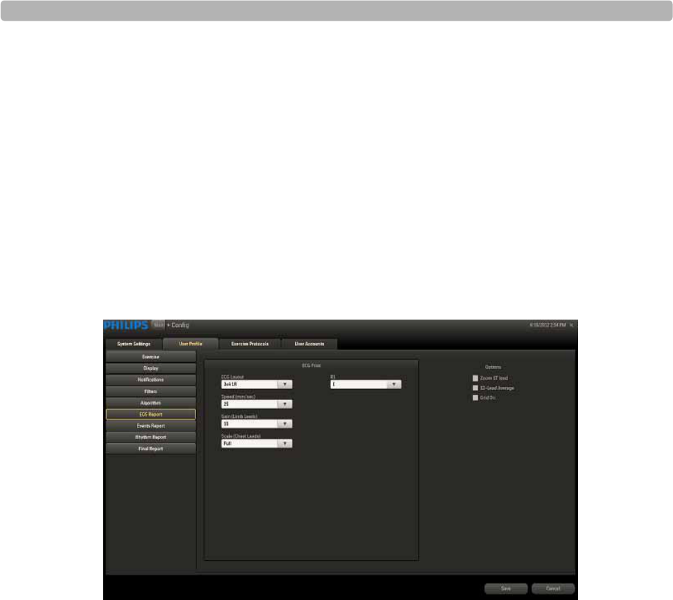
Working with Reports
4-28 ST80i Stress Test System Instructions for Use
ECG Report
The print report settings for the ECG Report include:
ECG Layout (select lead format)
Speed
Gain
Scale
R1
Options (Zoom ST Map, 12-Lead Average, Grid On)
Figure 4-11 ECG Report Settings
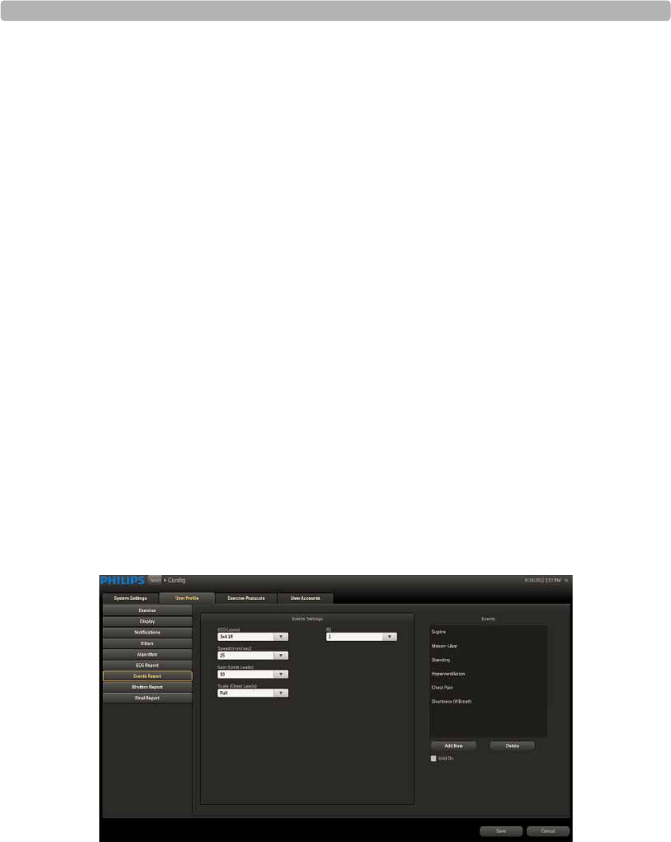
Printing Reports
ST80i Stress Test System Instructions for Use 4-29
Events Report
The print report settings for the Events Report include:
ECG Layout (select lead format)
Speed
Gain
Scale
R1
Events
–Supine
– Mason-Likar
– Standing
– Hyperventilation
–Chest Pain
– Shortness of Breath
Add New
Delete
Grid On
Figure 4-12 Events Report Settings
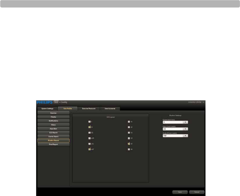
Working with Reports
4-30 ST80i Stress Test System Instructions for Use
Rhythm Report
The print report settings for the Rhythm Report include:
ECG Layout (select leads)
Rhythm Settings
–Speed
–Gain
– Scale
Figure 4-13 Rhythm Report Settings
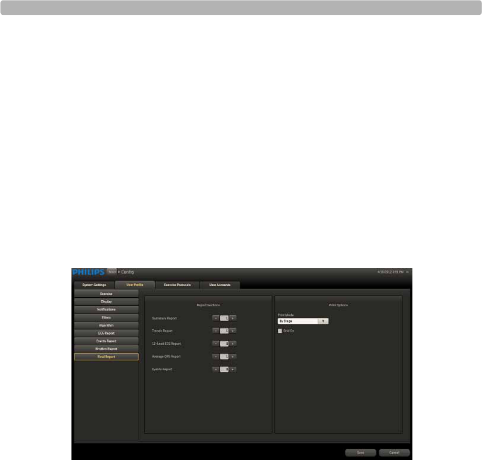
Printing Reports
ST80i Stress Test System Instructions for Use 4-31
Final Report
The print settings for the Final Report include:
Summary Report (set number of copies)
Trends Report (set number of copies)
12-Lead ECG Report (set number of copies)
Average QRS Report (set number of copies)
Events Report (set number of copies)
Print Options
– Print Mode (By Stage, By Minute)
–Grid On
Figure 4-14 Final Report Settings
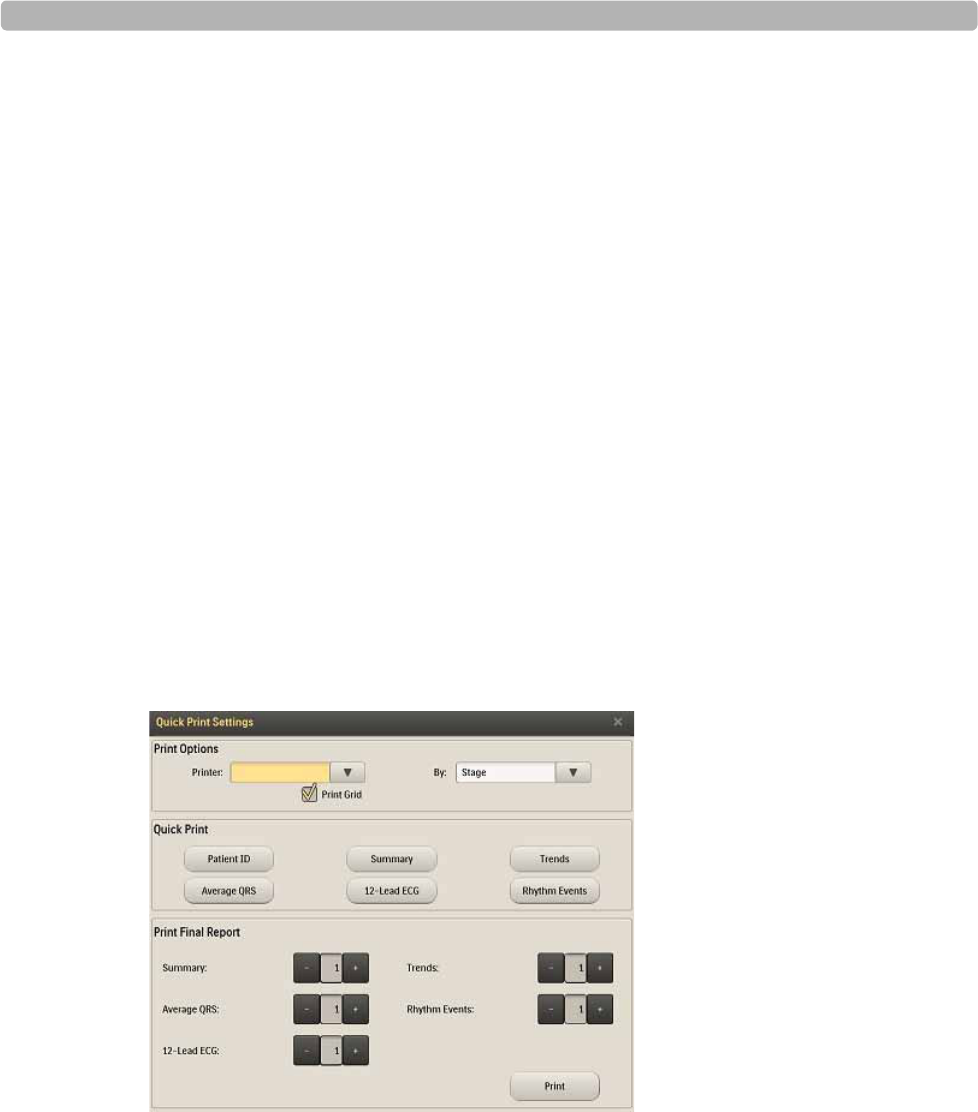
Working with Reports
4-32 ST80i Stress Test System Instructions for Use
Print (Quick Print Settings) Button
On the Report screen, the Print button on the Procedure bar is used for printing both the Final
Stress Report and individual reports. With the Quick Print Settings feature, you can override
the following preconfigured settings:
Final Report
– Printer selection
– Print mode (by stage, by minute)
– Print Grid (on or off)
– Number of copies to print
Individual Reports
– Printer selection
– Print mode (by stage, by minute)
– Print Grid (on or off)
– Number of copies to print
When you click the Print button, the Quick Print Settings dialog box is displayed.
Figure 4-15 Quick Print Settings
Print Options
–Printer
– By Stage, By Minute
– Print Grid checkbox
Quick Print
– Patient ID

Printing Reports
ST80i Stress Test System Instructions for Use 4-33
– Average QRS
–Summary
– 12-Lead ECG
–Trends
– Rhythm Events
Print Final Report
– Summary [number of copies]
– Average QRS [number of copies]
– 12-Lead ECG [number of copies]
– Trends [number of copies]
– Rhythm Events [number of copies]
Print button
NOTE Regardless of which option you choose, a Summary Report will always be printed on the first page of a
final report.
You have the option to de-identify or hide a patient's name on individual to final reports before
printing. See “De-Identify the Report” on page 4-35 for how to protect a patient's confidential
information when printing individual and final patient reports.
Printing the Final Report
The Final Stress Report includes:
Summary Report
NOTE The Summary Report cannot be printed without patient demographics.
Trends Report
12-Lead ECG Report
Average QRS Report
Rhythm Events Report
When you log into ST80i, the active settings of the filters are from a stored default set
associated with your log-in credentials. The same filter settings apply to both displayed and
printed waveforms. The filter settings are printed with the report.
NOTE A Patient ID Report is printed at the beginning of each stress test and also in the Final Stress Report.
To de-identify the report, see See “De-Identification” on page 3-46.

Working with Reports
4-34 ST80i Stress Test System Instructions for Use
To use the Print (Quick Print Settings) button to print the Final Stress Report
1Select the printer from the drop-down list:
– PDF Complete
– Microsoft XPS Document Writer
–Fax
– Local Thermal Printer
2Select the print parameters:
–By Stage
– By Minute
3Place a checkmark in the “Print Grid” box, if you want the grid to print on laser paper.
4Select the reports you want to include in the Final Stress Report.
5Select the number of copies to print for each report, using the minus (-) and plus (+)
indicators.
6Click the Print button.
For more information on the configuration of printers, see “Printer Configuration” on
page 4-25.
Printing Individual Reports
Both before and after you save the report, you can print individual reports using the Print
(Quick Print Settings) button on the Report screen.
See “De-Identify the Report” on page 4-35.
To use the Print (Quick Print Settings) button to print individual reports
1Select the printer from the drop-down list:
– PDF Complete
– Microsoft XPS Document Writer
–Fax
– Local Thermal Printer
2Select the print parameters:
–By Stage
– By Minute
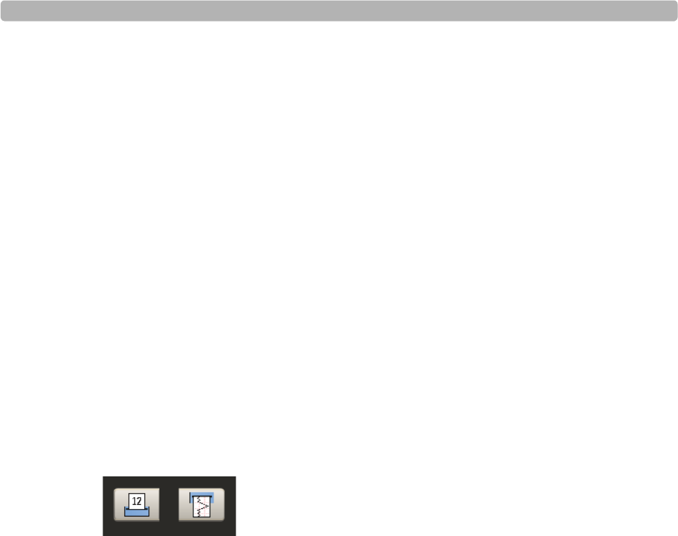
Printing Reports
ST80i Stress Test System Instructions for Use 4-35
3Place a checkmark in the “Print Grid” box, if you want the grid to print on laser paper.
4Select which report (or reports) you would like to print from the Quick Print section:
– Patient ID
– Average QRS
–Summary
– 12-Lead ECG (Full Disclosure)
–Trends
– Rhythm Events
Post-Recovery ECG Printing
The two print options at the bottom of the Report screen are used to print the current lead (or
any lead you select) during Post-Recovery.
Print 12-Lead ECG Report
Start Rhythm Printing
Figure 4-16 Print Options
When you click the Print 12-Lead ECG Report, you will get a printout of that segment of the
ECG.
When you click the Start Rhythm Printing button, a rhythm strip begins printing. To turn off
Rhythm Printing, click this button again.
De-Identify the Report
You have the option to hide the patient's name when printing individual reports or the Final
Stress Report. This feature allows you to hide patient identification information to protect the
patient's identity. To de-identify the report, see “De-Identification” on page 3-46.

Working with Reports
4-36 ST80i Stress Test System Instructions for Use
Working with Archived Reports
The Report database (also referred to as stress study database or stress study archive) is a long-
term repository for on-line storage and access of stress study data. It may be located in either
of the following:
on a stress device for stand-alone stress device configuration, or
on a central server, shared by one or more stress devices, in a “central system”
configuration
All the stored stress tests can be loaded for full disclosure review. Once a test is loaded from
the stress database, you can print the full data directly or print it after the final report from the
Report screen.
For each stress study, a database is generated to archive patient demographics, reports, and full
disclosure data. Together with the stress study data, patient information, the events captured
during the testing, protocol settings and the algorithm output are also saved into this database.
The final report raw data and metadata is archived to the system database hosted locally on the
device. he final report in PDF format can be exported to and stored on a central system.
Report (Stress Study) Database
Access to the Report database is determined by role and permission level, which are associated
with your log-in credentials. Functions that you are not authorized to perform are disabled on
the screen. Only users with proper credentials are allowed access to the stored tests.
To display the Archive screen
Click Report on the Main screen.
The Archive screen appears, listing all stored reports. A vertical scroll bar appears on the right
side when the list is longer than the available space on the screen.
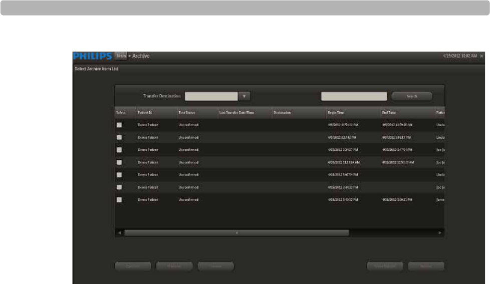
Working with Archived Reports
ST80i Stress Test System Instructions for Use 4-37
Figure 4-17 Select Archive From List Screen
Database Configuration
ST80i consists of two major components:
Client side – provides the clinical interface to the patient and user interface to the
technician. It handles the patient's data acquisition, stress procedure workflow, data
analysis, stress report presentation and raw data storage.
Server side – provides data storage and retrieval for the stress final reports in PDF format.
The server side also provides support for workflow, audit/tracking, and user
authentication / authorization (deferred).
The Client and Server components may be co-located on the same physical PC, or may be
installed on separate PC platforms.
In each mode, the data store limit is determined by the storage capacity of the hard disk.
See the ST80i Installation and Configuration Guide regarding database storage on networked
devices.
Depending on your facility's network configuration, ST80i can either work as a single,
stand-alone device or as a set of multiple, connected devices. As a stand-alone device, ST80i
provides basic server functions to perform a stress test, such as user security, configuration
management, and ECG data storage.
NOTE All reports (including unconfirmed/non-finalized reports) should be maintained in the Archive.
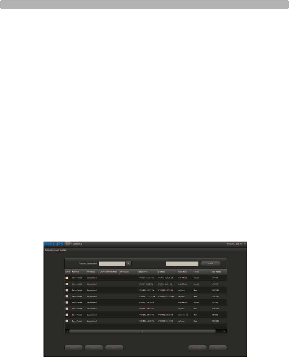
Working with Reports
4-38 ST80i Stress Test System Instructions for Use
STAND-ALONE DEVICE
If you are using a stand-alone device with built-in stress study database deployment, all
exercise stress test reports will be permanently stored in the device database archive.
Using a stand-alone device, you can review, edit, save and sign the stress report from the
Report screen.
The locally stored stress test is viewable and printable from the Report screen.
CENTRAL SERVER
In addition to local storage, you can configure archived stress tests in multiple networked
locations.
When several ST80i devices are connected, a backend system server is used to provide the
data storage service. In this mode, each ST80i device must maintain the raw data of the stress
studies and the final stress study report in PDF format that can be transferred to the central
database when network connection is available.
The stress test on the central server is stored in PDF format that is viewable on the client side.
The PDF filename is a 128-bit GUID.
Patient Reports
The Archive screen provides a list of archived stress tests that are stored locally or on the
server.
Figure 4-18 Select Archive from List Screen
The Select Archive from List screen includes the following information:
Patient ID
Test Status

Working with Archived Reports
ST80i Stress Test System Instructions for Use 4-39
Last Transfer Date/Time
Destination
Begin Time
End Time
Patient Name
Gender
Date of Birth
The test status is listed as follows:
Confirmed
Unconfirmed
Exported
From the Select Archive from List screen, you can:
Search for reports
Confirm reports
Transfer reports
Delete one or more stored reports (administrative users only)
Backup reports to another location (administrative users only)
Restore reports from another location (administrative users only)
View reports
Replay reports
NOTE A stress study report cannot be confirmed or exported to TMVue if its required patient fields are not
complete.

Working with Reports
4-40 ST80i Stress Test System Instructions for Use
Search for Reports
The Archive screen allows you to search for reports to confirm, transfer, delete, backup,
restore, view, or replay. You may search for reports by using the Search textbox and button or
by using the column headings to sort the reports.
To search for reports using the Search textbox and button
1Type the search criteria into the textbox to the left of the Search button. You may use
Patient ID, Patient Last Name, or Patient First Name as search criteria.
Figure 4-19 Search Textbox and Button
2Click Search.
The Select Archive from List screen displays only the results that match the search
criteria.
To search for reports using column headings to sort the reports
Click a column heading (e.g., “Patient ID,” “Patient Name”) to sort archived patient
reports.
The Archive screen sorts the contents of that column in ascending or descending order.
Click the column heading again to reverse the sorting order
Confirm a Report
To confirm a patient report -- procedure in development--
1Select the patient by putting a checkmark in the box by the patient ID.
2Click the Confirm button.
3
4
A stress study report cannot be confirmed or exported to TraceMasterVue if the required patient
fields are not complete.
Transfer Reports
To transfer a patient report -- procedure in development--
You can select single or multiple reports to export to a remote server. When exporting multiple
reports, you can cancel the exporting command. Any error during the operation should be
clearly prompt and will not block the whole operation.
1Select the patient report(s) to transfer by putting a checkmark in the box(es) in the Select
column to the left of the Patient ID.
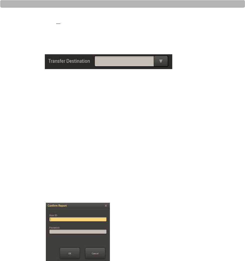
Working with Archived Reports
ST80i Stress Test System Instructions for Use 4-41
NOTE To select all of the reports, click the Select column heading; to deselect all of the reports, click the
Select column heading again.
2Select the destination for the transfer from the Transfer Destination drop-down list.
Figure 4-20 Transfer Destination Drop-Down List
3Click the Transfer button.
Delete Reports
If you have administrative privileges, you can select single or multiple stress studies to delete.
When doing this, you will be warned about the potential data lost. When deleting multiple
studies, you can also cancel the operation to stop the delete process.
To delete reports
1Select the patient report(s) to delete by putting a checkmark in the box(es) in the Select
column to the left of the Patient ID.
2Click the Delete button.
The Confirm Report window is displayed
Figure 4-21 Confirm Report Window
3Type your User ID and password, and click OK.
The Delete Selected Reports window is displayed.
Working with Reports
4-42 ST80i Stress Test System Instructions for Use
Figure 4-22 Delete Selected Report Window
WARNING This procedure will permanently delete the reports (raw data and metadata) from the local database
or the PDF reports from the central server.
4Click OK to delete the report(s); click Cancel to exit.
Backup Reports
If you have administrative privileges, you can select single or multiple stress studies to backup
to another location.
To backup reports -- procedure in development--
1
2
3
4
5
Restore Reports
If you have administrative privileges, you can select single or multiple stress studies to restore
from another location.
To restore reports -- procedure in development--
1
2
3
4
5

Working with Archived Reports
ST80i Stress Test System Instructions for Use 4-43
View a Report
To view a saved patient report
1Select the patient report by putting a checkmark in the box by the patient ID.
2Select the View Report button.
The Report screen opens.
NOTE Double-clicking on the study record also brings up the report
Replay a Report
To replay the patient ECG from the Archive screen
1Select the patient report by putting a checkmark in the box by the patient ID.
2Click the Replay button.
The Patient Session is loaded, beginning with Exercise.
This option provides you with the ability to scan the entire ECG from start to end.
When reviewing the stored stress test, you can change the J+ms value and change the
reference ECG. The stress study data and configuration settings are saved in database.
Viewing Reports Saved as PDF Files
To view a PDF file
1Exit the ST80i application.
2From Windows Explorer, locate and select the directory where the file was exported.
3Locate the file you want to review and double-click it.
Adobe Acrobat Reader automatically opens and displays the file.
4Press Page Down and Page Up to navigate through the file.
If ST80i is connected to a printer, you can print the file by selecting File, then Print.

Working with Reports
4-44 ST80i Stress Test System Instructions for Use
Exporting Reports (Export Exam)
When a final stress report is saved, it may then be exported to the central server. The report
can be finalized and signed on both device side and server side. The stress study raw data will
be saved in local stress study database. The export status and date/time of last export are also
maintained.
The final stress report may also be exported into a PDF file format. The PDF format can be
used on any PC for review and then emailed to the referring physician. It is also possible to
export a report directly to external media such as a USB flash stick in PDF format.
NOTE To export a report, you need the appropriate permission level.
Additionally, you can export PDF files for import into the Philips IntelliSpace Enterprise ECG
Manager (version C.04 and later) or the Philips TraceMasterVue ECG Management System
(version C.01 through C.03) for storage and archiving. See “Exporting Reports to an ECG
Management System” on page 4-46 for more information.
You can still print the report from ST80i at any time. You can also print the PDF file through
Adobe Acrobat. The exported report follows all the settings for the final stress report. See
“Printing the Final Report” on page 4-33.
On the Report screen, you can select ECGs from a storage location and copy/export them to a
remote system using the Copy/Transmit function. The format of the exported study record is
PDF.
ST80i’s Trinity Support allows for export of ECG data in ST80i format for inclusion in
a combined Stress/Echo image report. The folders used for raw data sharing with Trinity for
Q-Station, need to be locked down by appropriate folder permissions on the shared drive.
See the ST80i Installation and Configuration Guide for how to create folder permissions to
protect data.
To export a final stress report
1Click the Confirm button.
2Fill in your User Name and Password
3Click OK.
NOTE A stress study report cannot be confirmed or exported to TMVue if its required patient fields are not
complete.
External Storage of Stress Study data
If you have administrator access, you can copy stress study data from the Report database and
move the information to an external storage location (such as removable hard disk and USB
stick).

Exporting Reports (Export Exam)
ST80i Stress Test System Instructions for Use 4-45
ST80i provides an indication that the stress data has been copied to an external location. Once
the Stress study data has been copied/moved to an external location, it may be deleted if
desired. If deleted, a pointer will remain in the stress study database indicating that the data
had been moved to external storage.
An alert indicates the exporting status, i.e. success or failure. If failure, the error code should
be also provided.
In addition to local storage, you can configure archived stress tests in multiple networked
locations. On a stand-alone single device with built-in stress study database deployment, all
stress test reports are permanently stored in the device database archive.
ECG Export Destination Sites
You may select the destination site from a list of preconfigured sites. Each preconfigured site
includes the following information:
Site label (user-defined)
If the site is on a network, address and other connection details (URL, node number, etc.)
The following remote system types are supported:
– TraceMasterVue
–ECG Gateway
Once the connection is established, all selected ECGs are transferred to the remote site. After
each ECG has been successfully transmitted, the information is logged.
If the connection fails, the operator is given an alert. No attempt is made to automatically retry
the operation.
A maximum of 100 Remote Sites profiles can be created without noticeable performance
degradation when switching screens.
To create remote sites, see the ST80i Installation and Configuration Guide.

Working with Reports
4-46 ST80i Stress Test System Instructions for Use
Exporting Reports to an ECG Management System
You can export PDF files for import into the Philips IntelliSpace Enterprise ECG Manager
(version C.04 and later) or the Philips TraceMasterVue ECG Management System (version
C.01 through C.03). You can review the ECG, as well as store it in the database. You cannot,
however, edit the imported PDF file. For details about working with the imported PDF report,
refer to the ECG management system documentation.
If you are exporting to an ECG manager, shared folders with the appropriate permissions must
be set up on the server. You can specify a separate profile for each type of exported file and
also to export to different directories. Check with your system administrator to see which
profile you should use to export to the IntelliSpace or TraceMasterVue systems.
File Naming Conventions
ST80i saves files in a particular naming convention. It is very important that you do not
change this convention and that you enter all required information in the Patient Information
screen. Files that are not named properly will get sent to the TraceMasterVue Error directory.
CAUTION The underscore, square brackets, and lack of spaces are always present in the file name and are not
removable. They are required for proper parsing of the PDF files during import into the
TraceMasterVue database. Stress files must conform to the naming conventions specified here to be
able to be imported into the TraceMasterVue database.

Exporting Reports (Export Exam)
ST80i Stress Test System Instructions for Use 4-47
ST80i file names are of the form: --- procedure in development--
SV_PatientID[Date+Time]FirstName_MiddleInitial_LastName.pdf
where
SV - required AppName format
PatientID - required
Patient identification number or MRN (if provided)
[Date+Time] - required
The date and time shown is the date and time that the study was acquired.
Date format: YYYYMMDD
Time format: HHMM
FirstName - optional
Patient first name
MiddleInitial - optional
Patient middle initial
LastName- optional
Patient last name
To export a report for TraceMasterVue
1Save the final report as described in “Saving the Final Stress Report” on page 4-23.
2Click Export to save it as a file.
If the file is named correctly, it will be exported to the directory specified in the Miscellaneous
tab of the User Profile Configuration window for import into TraceMasterVue.
3To automatically remove the report from ST80i after export, check Delete exam after
export.
IMPORTANT! You cannot recover deleted exams! Use this option, if at all, with great caution.
ST80i prompts you to confirm this selection.
ST80i places a Y next to this report in the Exp column on the Archive screen.

Working with Reports
4-48 ST80i Stress Test System Instructions for Use
Importing Reports
You can download pdfs from a TraceMasterVue remote site or import data from a Synapse
remote site.
Download Pdfs from a TraceMasterVue Remote Site
To download pdfs from a TraceMasterVue Remote Site -- procedure in development--
1On the Worklist tab of the Select Patient screen, select “TraceMaster” from the Location
drop-down list.
Figure 4-23 Location Drop-Down List
2From the Worklist, place a checkmark by the name of the patient for whom you want to
view a previous ECG.
3Click the Previous ECG button.
A list of the patient’s previous ECGs is displayed.
4.........Need steps to open the pdf....

Importing Reports
ST80i Stress Test System Instructions for Use 4-49
Import Data From a Synapse Remote Site
How to import data from a Synapse Remote Site -- procedure in development--
1On the Worklist tab of the Select Patient screen, select “Synapse” from the Location
drop-down list.
Figure 4-24 Location Drop-Down List
2Click the Download button.
The worklist is downloaded to the table.
3.....................Next steps???

Working with Reports
4-50 ST80i Stress Test System Instructions for Use

5
5-1
1Maintaining the ST80i System
This chapter describes routine maintenance and cleaning of your ST80i system. It provides the
following information:
Precautions . . . . . . . . . . . . . . . . . . . . . . . . . . . . . . . . . . . . . . . . . . . . . . . . . . . .5-1
Cleaning the ST80i System. . . . . . . . . . . . . . . . . . . . . . . . . . . . . . . . . . . . . . . .5-2
Maintaining the ST80i Thermal Printer . . . . . . . . . . . . . . . . . . . . . . . . . . . . . .5-4
Inspecting the ST80i Thermal Printer. . . . . . . . . . . . . . . . . . . . . . . . . . . . .5-4
Cleaning the ST80i Thermal Printer. . . . . . . . . . . . . . . . . . . . . . . . . . . . . .5-4
Testing Printer Operation . . . . . . . . . . . . . . . . . . . . . . . . . . . . . . . . . . . . . .5-5
Replacing the ST80i Thermal Printer Fuse . . . . . . . . . . . . . . . . . . . . . . . .5-5
Cleaning the Equipment . . . . . . . . . . . . . . . . . . . . . . . . . . . . . . . . . . . . . . . . . .5-7
Precautions
Before cleaning any equipment, unplug the AC power cord connecting the equipment to
the power source.
Do not attempt to clean the device or patient cables by submersing into a liquid,
autoclaving, or steam cleaning.
Wipe the exterior surface of the device and patient cables with a non-alcohol sterilizing
disinfectant, and then dry with a clean cloth.
Conductive parts of the patient cable, electrodes, and associated Type CF connections,
including the neutral conductor of the patient cable and electrode, should not come into
contact with other conductive parts, including earth ground.
Do not pull or stretch patient cables as this could result in mechanical and/or electrical
failures. Patient cables should be stored after use by forming them into a loose loop.
Proper patient preparation is important for proper application of ECG electrodes and
operation of the device.
Patient cable exteriors should be checked for cracks or breakage prior to use.
As defined by IEC 60601-1 and IEC 60601-2-25, the device is classified as follows:
– Class I equipment
– Type CF applied parts
Are these correct???

Maintaining the ST80i System
5-2 ST80i Stress Test System Instructions for Use
– Ordinary equipment
– Not suitable for use in the presence of flammable anesthetics
– Continuous operation
CAUTION Dispose of waste material according to local regulations and laws regarding medical and battery waste.
Cleaning the ST80i System
To clean the system, including PC, monitor, and transport cart
Clean the mouse every month, as follows:
aRemove the ball from the mouse base.
bWipe the ball with a dry cloth.
cReassemble the mouse.
Clean the keyboard with a damp cloth, as necessary.
Clean the outside of the computer with a soft cloth lightly moistened with a mild detergent
solution. Do not use solvents or abrasive cleaners.
Clean the display with a soft cloth lightly moistened with a mild detergent approved for
use on the display. Do not use solvents or abrasive cleaners.
Clean the cart with a damp cloth, as necessary.
ST80i components should withstand cleaning using a cloth dampened with the following solutions.
IMPORTANT! This applies only to "Philips Healthcare custom-designed components". For all COTS components,
including laser printers, LCD displays, keyboards, and mice, customers must follow the manufacturers'
cleaning specifications.
Isopropyl alcohol, 70% solution
Mild soap and water
Chlorine bleach (5.25% sodium hypochlorite content), 3% solution in water
Steris Coverage Plus NPD, 1/2 fluid ounce per gallon water (one part Coverage Plus NPD
to 256 parts water)
Labels and graphics are to remain intact and legible. There is to be no damage, discoloration,
stress cracking or crazing of parts, cracking or elastomeric swelling. Parts shall not be attacked
to the degree that they lose their gloss or become sticky or gummy.

Maintaining the ST80i Thermal Printer
ST80i Stress Test System Instructions for Use 5-3
Maintaining the ST80i Thermal Printer
You should implement a satisfactory cleaning and inspection schedule for this equipment for
proper equipment operation and to reduce the possibility of equipment failure.
NOTE There are no serviceable parts for this printer. Should you experience problems with the printer, it is
replaced as a whole.
Inspecting the ST80i Thermal Printer
Inspect the equipment for the following conditions on a regular basis:
Examine power cable and the network cable for obvious damage (for example, torn
insulation, broken connectors, and so on). Replace cables as necessary.
All cords and connectors are securely seated in their corresponding connections.
Examine the equipment for missing screws, cracks or broken areas that might allow
unintended access to internal electronics areas
Cleaning the ST80i Thermal Printer
NOTE If the system is configured with a laser printer, refer to the User Guide provided
with the printer for maintenance and cleaning instructions.
To clean the printer
1Disconnect the power source.
2Clean the exterior surface of the unit with a damp cloth using a solution of mild
dishwashing detergent diluted in water.
3After washing, thoroughly dry off the unit with a clean, soft cloth or paper towel.
Clean the print head monthly, as described next.
To clean the print head
NOTE Do not let soap or water come into contact with the writer, plugs, jacks or vents.
1Open the writer door.
2Lightly rub the print head with an alcohol pad.
3Wipe with a clean cloth to remove alcohol residue.
4Allow the print head to air dry.
5Clean the platen by using adhesive tape. Apply the tape and pull it off. Rotate roller and
repeat until entire roller is clean.
6Clean the paper sensor.

Maintaining the ST80i System
5-4 ST80i Stress Test System Instructions for Use
Testing Printer Operation
After inspecting and cleaning the thermal printer, confirm that the printer is working properly.
To test printer operation
Using an ECG simulator with the stress testing system, acquire and print ECGs of known
amplitude.
A successfully printed ECG report has the following characteristics:
Printing should be dark and even across the page.
There should be no evidence of print-head dot failure (for example, breaks in printing
forming horizontal streaks).
Paper motion should be smooth and consistent during printing.
Waveforms should appear normal, with proper amplitude, and without distortion or
excessive noise.
Paper should stop with perforations near the tear-bar (indicating proper cue sensor
operation).
Replacing the ST80i Thermal Printer Fuse
The AC fuse needs to be replaced when the AC power on indicator light does not illuminate
when the printer is plugged into AC power.
Figure 5-1 AC power on indicator light on ST80i thermal printer
AAC power on indicator light

Maintaining the ST80i Thermal Printer
ST80i Stress Test System Instructions for Use 5-5
Only use replacement AC fuses with Philips part number 453564131221, or use a 1.6 amp
(250V) time-delay fuse the same size and configuration as the original fuse.
Figure 5-2 Replacing the AC Fuse
To replace the AC fuse
1Unplug the thermal printer from AC power. Pull out the AC power cord from the AC
power connector on the rear of the printer.
2Locate the AC fuse, which is directly below the AC power connector.
3Push on both ends of the fuse and pull out the fuse from the fuse holder slot.
4Insert the new fuse using the same orientation.
5Push the fuse all the way into the fuse holder slot. The fuse snaps into place.
AAC Fuse

Maintaining the ST80i System
5-6 ST80i Stress Test System Instructions for Use
Cleaning the Equipment
The wireless patient module (PIM), PIM holder, and lead wires must be cleaned after each use.
To clean the PIM, PIM holder, USB interface, and lead wires
1Dampen a soft cloth with one of the disinfectants or cleaning agents listed below.
Clean the lead wires with any of the following:
– Cidex Ortho Phthaladehyde
– Cetylcide
– Vesphene 2 Aqueous Phenolic Germicidal Agent
CAUTION Do not:
Use isopropyl alcohol
Autoclave the patient module, patient cable/lead wires, or use ultrasonic cleaners
Immerse
Use abrasive materials
Wet the connectors
2Wring excess moisture from the cloth before cleaning.
3Simply wipe off the exterior of the PIM, PIM holder, and the USB interface connector.

A
A-1
Appendix ATroubleshooting and Contacting the
Response Center
When you encounter a problem working with ST80i, address the issue in the following order:
1Review the Troubleshooting chapter to see if your issue is addressed.
2Contact your ST80i administrator.
3Contact the Philips Healthcare Customer Care Solution Center.
The Philips Response Center can assist with product troubleshooting and provide technical
expertise to help with any issue with the ST80i system. For details, visit the following URL on
the Web:
www.medical.philips.com/main/services/response_center
This appendix provides the following information:
Troubleshooting ST80i Issues . . . . . . . . . . . . . . . . . . . . . . . . . . . . . . . . . . . . .A-2
Contacting Technical Support . . . . . . . . . . . . . . . . . . . . . . . . . . . . . . . . . . . .A-10
Philips Healthcare Customer Care Solution Center. . . . . . . . . . . . . . . . .A-10
Troubleshooting and Contacting the Response Center
A-2 ST80i Stress Test System Instructions for Use
Troubleshooting ST80i Issues
When you are using ST80i, you may encounter some problems with the system. The following
table describes some of the more common symptoms and provides information regarding
possible causes, and solutions to help you solve potential problems.
Table A-1 Troubleshooting ST80i issues
Problem Cause Solution
Waveform Issues
Baseline drift Poor skin-to-electrode contact. Re-prep skin and replace faulty electrodes.
A red dashed line
displayed on the
real-time ECG display
Lead failure caused by
inadequate skin-to-electrode
contact.
Broken lead wire.
RF interference (wireless
option only).
Faulty PIM/USB module
Correct the faulty lead identified on the
lead map dialog.
Replace the lead wire.
If problem persists, contact the Response
Center.
Perform an RF scan to determine the
presence of RF interference. Select the
optimal channel. Ensure the channel
specified in the ST80i application and on
the wireless patient module is the same.
Reseat USB cable.
Ensure correct USB type is selected in
System Settings.
ECG artifact caused by
muscle interference. Electrode placed over an area of
muscle or fatty tissue. Find a stable electrode site, re-prep the skin,
and apply a new electrode away from
muscular and fatty areas.
Troubleshooting ST80i Issues
ST80i Stress Test System Instructions for Use A-3
System Navigation Issues
No response to
keyboard commands.
USB cable connection. Check USB cable connection.
Disconnect and connect the keyboard to
check whether keyboard can be
identified by the system
Cursor does not move USB cable connection. Check USB cable connection.
Disconnect and connect the mouse to
check whether mouse can be identified
by the system.
Treadmill Issues
Treadmill does not
respond to the On
command from ST80i
Equipment was powered up
in the wrong sequence.
The Treadmill power switch
is in the Off position, or the
treadmill cable is not properly
attached.
The Emergency Stop button
is engaged.
Turn the treadmill off by using the Stop
Treadmill button. Wait one minute and
turn the power On. Proceed with the test.
Ensure the correct equipment is specified
in the Configuration settings.
Check the treadmill-to-ST80i cable
connection. Turn the Treadmill main
power switch to the On position. The
switch is located at the base of the
treadmill hood, on the left side.
Ensure the correct COM port is
configured.
Reset the Emergency Stop button by
turning it clockwise one quarter turn.
System Error Messages
Error message appears:
No exams are currently
selected
An attempt to access a final report
is made, but no patient is selected
from the list.
Click on the patient name to select it, then
access the file.
Table A-1 Troubleshooting ST80i issues
Problem Cause Solution
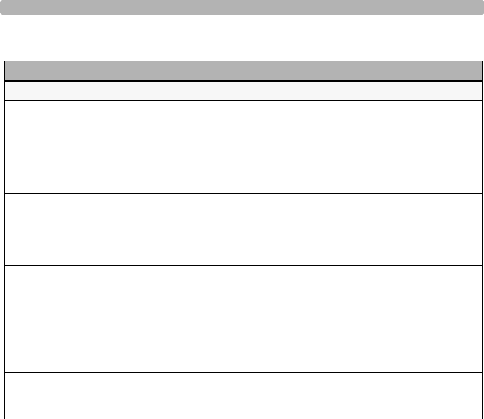
Troubleshooting and Contacting the Response Center
A-4 ST80i Stress Test System Instructions for Use
System Error Messages (continued)
Error message appears:
Not all of the selected
exams are reported
An attempt was made to print
or export a final report from
the Archive Manager but the
report has not been saved as
Reported.
A test is labeled Reported only after it is
saved.
Click Save Report, then export the final
report.
Error message appears:
Not reported exam
An attempt to print a final
report from the Report screen
is made but the report has not
been saved as Reported.
A test is labeled Reported only after it is
saved.
Click Save Report, then export the final
report.
The Lead Map display
a red “X” on one or
more connections
One or more leads have failed. Connect the electrodes. Once connected, the
warning message disappears.
An error occurred
during export of
selected exams
One or more leads have failed. Check Export directory.
Check remote location.
Try pinging remote location.
Error message appears:
No stage selected
In the protocol edit function, an
attempt is made to edit a stage,
but no stage has been selected.
Double-click on the stage to edit. The Edit
window appears, allowing you to change the
stage parameters.
Table A-1 Troubleshooting ST80i issues
Problem Cause Solution

Troubleshooting ST80i Issues
ST80i Stress Test System Instructions for Use A-5
Printer Issues
Thermal printer
paper out light is
on
Thermal printer is
not printing
Uneven printing of
ECGs or reports
Paper jammed.
No paper in tray.
Open writer door.
Printer head needs cleaning.
Paper door not closed
completely.
Open writer cover and remove jammed
paper.
Insert new pack of paper in tray.
See if writer door is latched.
Verify that the correct printer is specified
in the configuration settings. See “Printer
Configuration” on page 3-42.
Refer to cleaning instructions in
Chapter 5, “Maintaining the ST80i
System.”
See if paper door is closed completely.
Uneven printing Possible causes of uneven
printing:
Print head itself
Platen
Poor or damaged paper
Mechanical misalignment of
the print head
Have a technician:
Check the platen for uneven wear.
Verify that the print head shoulder screws
are secure before replacing the print
head.
The shoulder screws that secure the print
head should be properly centered in their
holes, allowing the print head slight
vertical movement.
Gaps in printing Print head and signal cables
may have a short or damaged
connectors
Defective print head
Faulty circuit board
Defective paper
Dirty print head
Have a technician:
Check the print head and signal cables
for shorts, opens, or damaged connectors.
These cables plug in between the circuit
board and the thermal print head.
Check the print head and circuit board
and replace as needed.
Replace the paper, using a fresh pack of
properly stored paper.
Clean the print head.
Table A-1 Troubleshooting ST80i issues
Problem Cause Solution

Troubleshooting and Contacting the Response Center
A-6 ST80i Stress Test System Instructions for Use
Printer Issues (continued)
No printing LAN settings may be
incorrect.
Network cable may be loose.
Power cord may be
disconnected.
Printer might not have paper
loaded.
Printer error.
Check to see that the Local Area
Network Connection Properties settings
on the PC are defined correctly
Ensure that a crossover network cable is
used and check connections.
Make sure both printer LAN LEDs
(Amber and green) are lit
Ensure the printer port is enabled.
Check AC power cord connections and
confirm that the Power On indicator is
illuminated.
Check to see that paper has been loaded
and that it has been loaded correctly.
Paper sensor mark is at the bottom right.
No motor drive Insufficient paper tension
Faulty writer assembly
Faulty circuit board
Check and replace as needed.
Defective paper Thermal paper that is old or that
was improperly stored can cause
light or uneven printing.
Exposure to heat or chemical
vapors can damage the paper.
Test printer using a fresh pack of properly
stored paper.
Blood pressure printout
and report discrepancy Use of NIBP field to enter new
blood pressure values. You must enter blood pressure values using
the BP mmhg field in the Side Panel.
For details on entering blood pressure values,
see “NIBP & SpO2” on page 3-29.
Table A-1 Troubleshooting ST80i issues
Problem Cause Solution
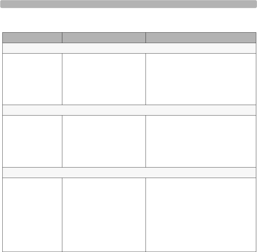
Troubleshooting ST80i Issues
ST80i Stress Test System Instructions for Use A-7
Data-Entry Issues
Cannot manually enter
patient data It is possible that the Export HL7
check box has been inadvertently
selected on the Miscellaneous tab
in the Configuration settings.
For the affected profile(s), do the following:
1Click Settings, then click the
Miscellaneous tab.
2Ensure the Export: HL7 check box is clear.
3Click Save Profile and Exit.
Wireless Patient Module Issues
Packet errors/ signal
drop Signal on the screen shows a red
dashed line. Configure the system to automatically hop
the RF channel, or perform an RF Scan to
locate the source of the interference and to
change to the optimal channel for the
wireless patient module. For details about the
wireless settings, see the ST80i Wireless
Patient Module Instructions for Use.
Wireless Patient Module Issues (continued)
No waveform signal on
the screen With the patient (or simulator)
connected, no waveforms are
displayed; only the red dashed
line and lead-fail indicator appear.
NOTE If neither the signal nor the
red dashed line is present, click the
“X” in the upper right corner of the
screen, and then click OK in the
“Abort Test” dialog box.
Check the ST80i System settings, as well as
the wireless patient module to ensure that the
two units are set to the same channel.
For details about setting the receiving
channel settings, see the ST80i Installation
and Configuration Guide.
For details about the wireless settings, see the
ST80i Wireless Patient Module Instructions
for Use for instructions.
Table A-1 Troubleshooting ST80i issues
Problem Cause Solution
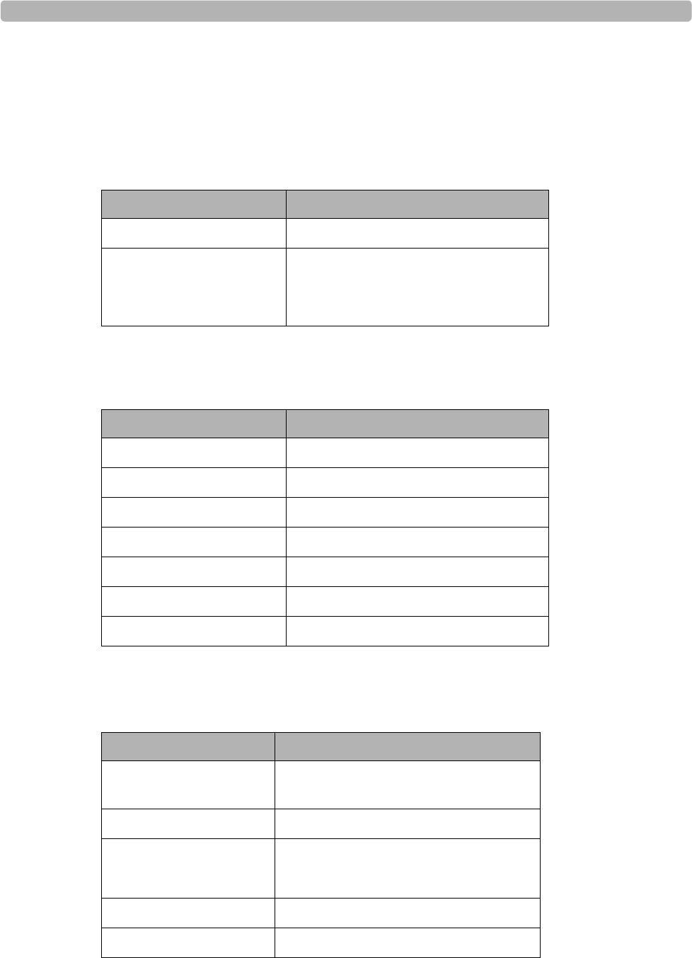
Troubleshooting and Contacting the Response Center
A-8 ST80i Stress Test System Instructions for Use
Contacting Technical Support
Philips Healthcare Customer Care Solution Center
North America
Country Telephone Number
Canada (800) 323 2280
United States
Miami
(Spanish speaking)
(800) 722-9377, press option 3
954 835 2650
South America
Country Telephone Number
Argentina 54 11 4546 7698
Brazil 0800 701 7789
Chile 0800 22 3003
Mexico 01 800 710 8128
Columbia 01 8000 11 10 10
Peru 51 1620 6440
Puerto Rico 787 754 6811
Europe
Country Telephone Number
United Kingdom 07 002 432 58 472 or
07 002 HEALTHRC
Austria 01 25125 333
Belgium 32 2 525 7102 (French)
32 2 525 7103 (Flemish)
Finland 010 855 2455
France 0803 35 34 33
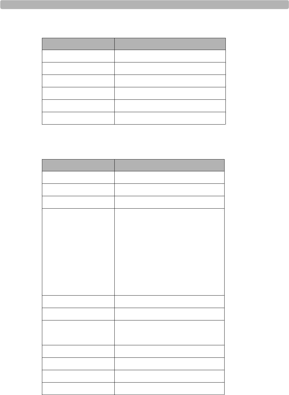
Contacting Technical Support
ST80i Stress Test System Instructions for Use A-9
Germany 0180 5 47 5000
Italy 0800 8256087
Netherlands 31 4 027 87630
Spain 34 90 230 4050
Sweden 08 5064 8830
Switzerland 0800 80 10 23
Asia Pacific
Country Telephone Number
Australia 1800 251 400
China 800 810 0038
Hong Kong 852 2876 7578
India
New Delhi
Mumbai
Calcutta
Chennai
Bangalore
Hyderabad
011 2695 9734
022 5691 2643/2431
2485 3718
044 555 01000
080 5091 911
040 5578 7974
Indonesia 021 794 7542
Japan 0120 381 557
Korea
Seoul
080 372 7777 (toll free)
02 3445 9010
Macau 0800 923
Malaysia 1800 886 188
New Zealand 0800 251 400
Philippines 02 845 7875
Europe
Country Telephone Number
Singapore 1 800 Philips
Taiwan 0800 005 616
Thailand 02 614 3569
Asia Pacific
Country Telephone Number

B
B-1
Appendix BProtocol Reference
This appendix provides an example of each of the included protocols. You can define and edit
protocols. For details, see ST80i Installation and Configuration Guide.
The following protocols are delivered with every ST80i system:
Bruce (page B-2)
Modified Bruce (page B-3)
Balke (page B-4)
Ellestad (page B-5)
Naughton (page B-6)
Pharmacological (page B-7)
Low Ramp (page B-8)
Medium Ramp (page B-9)
High Ramp (page B-10)
USAF/SAM 2.0 (page B-11)
USAF/SAM 3.3 (page B-11)
Cycle (Ergometer) (page B-12)
Astrand (page B-13)
The following sections provide an example of each of these protocols.
Protocol Reference
B-2 ST80i Stress Test System Instructions for Use
Bruce Protocol
This sample Bruce protocol produces the following operations and conditions:
A stage change occurs every 3 minutes with an increase in treadmill speed and grade.
Blood pressure is automatically measured at the end of each stage.
A 12-lead ECG report is automatically printed at the end of each stage. ECG acquisition
begins 10 seconds prior to the end of a stage.
In the Recovery phase, the treadmill slows to 1.5 mph and the following reports are
automatically printed:
–The
Peak Exercise ECG report prints immediately.
– A Recovery ECG prints in one minute.
– A Recovery ECG prints every two minutes until the end of the Recovery phase.
Blood pressure measurement is set to every 2 minutes (2, 4, 6, 8…) until the end of the
Recovery phase.
Table B-2 Bruce Protocol Settings
Bruce
Stage # Time
Duration
(mm:ss)
Speed
(mph) Grade
(%) ECG Print BP
Measurement
Pre-Exercise
1 Unlimited 1.0 0.0 Off Off
Exercise
1 3.00 1.7 10.0 End End
2 3.00 2.5 12.0 End End
3 3.00 3.4 14.0 End End
4 3.00 4.2 16.0 End End
5 3.00 5.0 18.0 End End
6 3.00 5.5 20.0 End End
7 3.00 6.0 22.0 End End
Recovery
1 3.00 1.5 0.0 Every
02:00
Every 02:00
Modified Bruce
ST80i Stress Test System Instructions for Use B-3
Modified Bruce
Table B-3 Modified Bruce Protocol Settings
Modified Bruce
Stage # Time
Duration
(mm:ss)
Speed
(mph) Grade
(%) ECG Print BP
Measurement
Pre-Exercise
1 Unlimited 0.5 0.0 Off Off
Exercise
1 3.00 1.7 0.0 End Begin
2 3.00 1.7 5.0 End Begin
3 3.00 1.7 10.0 End Begin
4 3.00 2.5 12.0 End Begin
5 3.00 3.4 14.0 End Begin
6 3.00 4.2 16.0 End Begin
7 3.00 5.0 18.0 End Begin
8 3.00 5.5 20.0 End Begin
9 3.00 6.0 22.0 End Begin
Recovery
1 3.00 1.0 0.0 Every
02:00
Every 02:00
Protocol Reference
B-4 ST80i Stress Test System Instructions for Use
Balke Protocol
The Pre-Exercise and Recovery phase settings are the same as for the Bruce protocol. See
Figure X-1, above.
Table B-4 Balke Protocol Settings
Balke
Stage # Time
Duration
(mm:ss)
Speed
(mph) Grade
(%) ECG Print BP
Measurement
Pre-Exercise
1 Unlimited 1.0 0.0 Of
f
Off
Exercise
1 1.0 3.3 1.0 End Off
2 1.0 3.3 2.0 End Off
3 1.0 3.3 3.0 End End
4 1.0 3.3 4.0 End Off
5 1.0 3.3 5.0 End Off
6 1.0 3.3 6.0 End End
7 1.0 3.3 7.0 End Off
8 1.0 3.3 8.0 End Off
9 1.0 3.3 9.0 End End
10 1.0 3.3 10.0 End Off
11 1.0 3.3 11.0 End Off
12 1.0 3.3 12.0 End End
13 1.0 3.3 13.0 End Off
14 1.0 3.3 14.0 End Off
15 1.0 3.3 15.0 End End
16 1.0 3.3 16.0 End Off
17 1.0 3.3 18.0 End Off
18 1.0 3.3 20.0 End End
19 1.0 3.3 21.0 End Off
20 1.0 3.3 22.0 End Off
21 1.0 3.3 23.0 End End
22 1.0 3.3 24.0 End Off
Recovery
1 3:00 1.0 0.0 Every
02:00
Every 02:00

Ellestad Protocol
ST80i Stress Test System Instructions for Use B-5
Ellestad Protocol
The Pre-Exercise and Recovery phase settings are the same as for the Bruce protocol. See
Figure X-1, above.
Table B-5 Ellestad Protocol Settings
Ellestad
Stage # Time
Duration
(mm:ss)
Speed
(mph) Grade
(%) ECG Print BP
Measurement
Pre-Exercise
1 Unlimited 1.0 0.0 Off Off
Exercise
1 3.00 1.7 10.0 End End
2 2.00 3.0 10.0 End End
3 2.00 4.0 10.0 End End
4 3.00 5.0 10.0 End End
5 2.00 6.0 15.0 End End
6 2.00 7.0 15.0 End End
7 2.00 8.0 15.0 End End
Recovery
1 3.00 1.5 0.0 Every
02:00
Every 02:00
Protocol Reference
B-6 ST80i Stress Test System Instructions for Use
Naughton Protocol
The Pre-Exercise and Recovery phase settings are the same as for the Bruce protocol. See
Figure X-1, above.
Table B-6 Naughton Protocol Settings
Naughton
Stage # Time
Duration
(mm:ss)
Speed
(mph) Grade
(%) ECG Print BP
Measurement
Pre-Exercise
1 Unlimited 0.5 0.0 Off Off
Exercise
1 2.00 1.0 0.0 End Off
2 2.00 2.0 2.0 End End
3 2.00 2.0 3.5 End Off
4 2.00 2.0 7.0 End End
5 2.00 2.0 10.5 End Off
6 2.00 2.0 14.0 End End
7 2.00 2.0 17.5 End Off
Recovery
1 3.00 1.0 0.0 Every
02:00
Every 02:00
Pharmacological Protocol
ST80i Stress Test System Instructions for Use B-7
Pharmacological Protocol
Table B-7 Pharmacological Protocol Settings
Pharmacological
Stage
# Time
Duration
(mm:ss)
Speed
(mph) Grade
(%) ECG
Print BP
Measurement Dose
Pre-Infusion
1 Unlimited 0.0 0.0 Off Of
f
Of
f
Infusion
1 3.00 0.0 0.0 End End Off
2 3.00 0.0 0.0 End End Off
3 3.00 0.0 0.0 End End Of
f
4 3.00 0.0 0.0 End End Off
5 3.00 0.0 0.0 End End Off
6 3.00 0.0 0.0 End End Of
f
7 3.00 0.0 0.0 End End Off
Pos
t
-Infusion
1 3.00 0.0 0.0 Every
01:00
Every 02:00 Off
Protocol Reference
B-8 ST80i Stress Test System Instructions for Use
Low Ramp Protocol
The Pre-Exercise and Recovery phase settings are the same as for the Bruce protocol. See
Figure X-1, above.
Table B-8 Low Ramp Protocol Settings
Low Ramp
Stage # Time
Duration
(mm:ss)
Speed
(mph) Grade
(%) ECG Print BP
Measurement
Pre-Exercise
1 Unlimited 1.0 0.0 Of
f
Off
Exercise
1 0:30 1.0 0.0 End End
2 0:30 1.1 1.0 End End
3 0:30 1.2 1.0 End End
4 0:30 1.3 2.0 End End
5 1:00 1.4 3.0 End End
6 0:30 1.5 4.0 End End
7 0:30 1.6 4.0 End End
8 0:30 1.7 5.0 End End
9 0:30 1.8 6.0 End End
10 1:00 1.9 7.0 End End
11 0:30 2.0 8.0 End End
12 0:30 2.1 8.5 End End
13 0:30 2.2 9.0 End End
14 0:30 2.3 9.5 End End
15 1:00 2.4 10.0 End End
16 0:30 2.5 10.5 End End
17 0:30 2.6 11.0 End End
18 1.00 2.7 12.0 End End
19 0:30 2.8 13.0 End End
20 0:30 2.9 14.0 End End
21 1.00 3.0 15.0 End End
22 0:30 3.1 16.0 End End
23 0:30 3.2 17.0 End End
24 1.00 3.4 18.0 End End
25 1:00 3.6 19.0 End End
Recovery
1 3:00 1.5 0.0 Every
02:00
Every 02:00
Medium Ramp Protocol
ST80i Stress Test System Instructions for Use B-9
Medium Ramp Protocol
The Pre-Exercise phase settings are the same as for the Bruce protocol. See Figure X-1, above.
Table B-9 Medium Ramp Protocol Settings
Medium Ramp
Stage # Time
Duration
(mm:ss)
Speed
(mph) Grade
(%) ECG Print BP
Measurement
Pre-Exercise
1 Unlimited1.0
Exercise
1 0:30 1.5 3.0 End End
2 0:30 1.6 4.0 End End
3 0:30 1.7 5.0 End End
4 0:30 1.7 6.0 End End
5 1.00 1.8 7.0 End End
6 0:30 1.9 8.0 End End
7 0:30 2.0 8.5 End End
8 0:30 2.1 9.0 End End
9 0:30 2.2 9.5 End End
10 1.00 2.3 10.0 End End
11 0:30 2.4 11.0 End End
12 0:30 2.5 11.5 End End
13 0:30 2.6 12.0 End End
14 0:30 2.7 12.5 End End
15 1.00 2.8 13.0 End End
16 0:40 3.0 13.5 End End
17 0:40 3.2 14.0 End End
18 0:40 3.4 14.5 End End
19 0:40 3.6 15.0 End End
20 0:40 3.8 15.5 End End
21 0:40 4.0 16.0 End End
22 0:40 4.2 17.0 End End
23 0:40 4.5 18.0 End End
24 0:40 4.8 19.0 End End
25 0:40 5.2 20.0 End End
Recovery
1 3:00 1.0 0.0 Every
02:00
Every 02:00
Protocol Reference
B-10 ST80i Stress Test System Instructions for Use
High Ramp Protocol
The Pre-Exercise phase settings are the same as for the Bruce protocol. See Figure X-1 on
page X. The Recovery phase settings are the same as for the Medium Ramp protocol. See
Figure X-8 on page Y.
Table B-10 High Ramp Protocol Settings
High Ramp
Stage # Time
Duration
(mm:ss)
Speed
(mph) Grade
(%) ECG Print BP
Measurement
Pre-Exercise
1 Unlimited 1.0 0.0 Of
f
Off
Exercise
1 0:30 1.6 5.0 End End
2 0:30 1.7 10.0 End End
3 0:30 1.7 10.0 End End
4 0:30 2.0 10.0 End End
5 1.00 2.2 11.0 End End
6 0:30 2.4 11.5 End End
7 0:30 2.5 12.0 End End
8 0:30 2.6 12.5 End End
9 0:30 2.8 13.0 End End
10 1.00 3.0 13.5 End End
11 0:30 3.2 14.0 End End
12 0:30 3.4 14.0 End End
13 0:30 3.5 14.5 End End
14 0:30 3.6 15.0 End End
15 1.00 3.7 15.5 End End
16 0:40 4.0 16.0 End End
17 0:40 4.2 16.0 End End
18 0:40 4.4 16.5 End End
19 0:40 4.6 17.0 End End
20 0:40 4.8 17.5 End End
21 0:40 5.0 18.0 End End
22 0:40 5.2 19.0 End End
23 0:40 5.5 20.0 End End
24 0:40 5.8 21.0 End End
25 0:40 6.0 22.0 End End
Recovery
1 3:00 1.0 0.0 Every
02:00
Every 02:00
USAF/SAM 2.0 Protocol
ST80i Stress Test System Instructions for Use B-11
USAF/SAM 2.0 Protocol
Table B-11 USAF/SAM 2.0 Protocol Settings
USAF/SAM 3.3 Protocol
Table B-12 USAF/SAM 3.3 Protocol Settings
USAF/SAM 2.0
Stage # Time
Duration
(mm:ss)
Speed
(mph)
Grade
(%)
ECG Print BP
Measurement
Pre-Exercise
1 Unlimited 0.5 0.0 Off Off
Exercise
1 3.00 2.0 0.0 End Off
2 3.00 2.0 5.0 End End
3 3.00 2.0 10.0 End Off
4 3.00 2.0 15.0 End End
5 3.00 2.0 20.0 End Off
6 3:00 2.0 25.0 End End
Recovery
1 3.00 1.0 0.0 Every
02:00
Every 02:00
USAF/SAM 3.3
Stage # Time
Duration
(mm:ss)
Speed
(mph)
Grade
(%)
ECG Print BP
Measurement
Pre-Exercise
1 Unlimited 1.2 0.0 Of
f
Off
Exercise
1 3.00 3.3 0.0 End Off
2 3.00 3.3 5.0 End End
3 3.00 3.3 10.0 End Off
4 3.00 3.3 15.0 End End
5 3.00 3.3 20.0 End Off
6 3:00 3.3 25.0 End End
Recovery
1 3.00 1.2 0.0 Every
02:00
Every 02:00
Protocol Reference
B-12 ST80i Stress Test System Instructions for Use
Cycle (Ergometer) Protocol
Table B-13 Cycle (Ergometer) Protocol Settings
Cycle (Ergometer)
Stage # Time
Duration
(mm:ss)
Powe
r
(Watts)
ECG
Print
BP
Measurement
Pre-Exercise
1 Unlimited 10 Of
f
Of
f
Exercise
1 3.00 25 Begin End
2 3.00 50 Begin End
3 3.00 75 Begin End
4 3.00 100 Begin End
5 3.00 125 Begin End
6 3.00 150 Begin End
7 3.00 175 Begin End
8 3.00 200 Begin End
9 3.00 225 Begin End
10 3:00 250 Begin End
Recovery
1 3.00 25 Every
01:00
Every 02:00
Astrand Protocol
ST80i Stress Test System Instructions for Use B-13
Astrand Protocol
Table B-14 Astrand Protocol Settings
Astrand
Stage # Time
Duration
(mm:ss)
Powe
r
(Watts)
ECG
Print
BP
Measurement
Pre-Exercise
1 Unlimited 50 Of
f
Of
f
Exercise
1 6.00 50 End End
2 6.00 100 End End
3 6.00 150 End End
4 6.00 200 End End
5 6.00 250 End End
6 6.00 300 End End
Recovery
1 3.00 50 Every
01:00
Every 02:00

Protocol Reference
B-14 ST80i Stress Test System Instructions for Use

C
C-1
Appendix AConfiguring and Using the Printer
The ST80i StressTest System supports the following different printers:
ST80i thermal printer
Network printer and local printer with Windows 7 drivers.
This appendix provides the following information:
ST80i Thermal Printer. . . . . . . . . . . . . . . . . . . . . . . . . . . . . . . . . . . . . . . . . . . C-1
Thermal Printer Dimensions and Specifications . . . . . . . . . . . . . . . . . . . C-2
Loading the Thermal Printer Paper. . . . . . . . . . . . . . . . . . . . . . . . . . . . . . C-5
Setting Up the Thermal Printer. . . . . . . . . . . . . . . . . . . . . . . . . . . . . . . . . C-6
Maintaining the Thermal Printer . . . . . . . . . . . . . . . . . . . . . . . . . . . . . . . C-8
Inspecting the ST80i Thermal Printer . . . . . . . . . . . . . . . . . . . . . . . . C-8
Cleaning the ST80i Thermal Printer . . . . . . . . . . . . . . . . . . . . . . . . . C-8
Testing Printer Operation . . . . . . . . . . . . . . . . . . . . . . . . . . . . . . . . . . C-9
About the Supported LaserJet Printers . . . . . . . . . . . . . . . . . . . . . . . . . . . . . C-10
For printer troubleshooting, see Appendix A, “Troubleshooting and Contacting the Response
Center.”
ST80i Thermal Printer
The ST80i thermal printer uses an eight-dot-per-millimeter (dpm) print head to print ECG
tracings and report data. Multiple print formats are supported.
The ST80i thermal printer includes:
Hospital-grade power cord for connection to the isolation transformer
USB cable for connection to the PC

Configuring and Using the Printer
C-2 ST80i Stress Test System Instructions for Use
Thermal Printer Dimensions and Specifications
Figure C-1 ST80i thermal printer dimensions
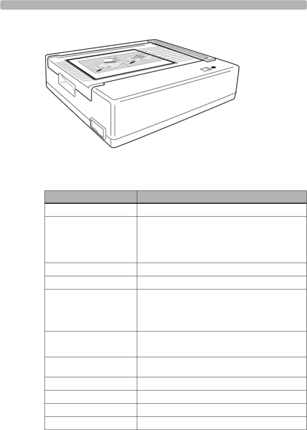
ST80i Thermal Printer
ST80i Stress Test System Instructions for Use C-3
Figure C-2 ST80i thermal printer
Table C-1 ST80i thermal printer specifications
Feature Specification
Instrument type Thermal printer
Paper type Supports the use of the following paper types supplied as
z-fold in packages of 100 and 200 sheets:
A-size Normal, Anti-fade, and Easy Tear
A4-size Normal, Anti-fade, thin, and Easy Tear
Recording technique Computer controlled, thermal dot array
Print-head width 8.5 inches (216 mm)
Print-head resolution Vertical: 200 dots/inch, vertical
Horizontal:
5, 10, and 25 mm/sec: 500 dots/inch
50 mm/sec: 250 dots/inch
Writer speeds 25 or 50 mm/sec for AUTO report
5, 10, 25, or 50 mm/sec for rhythm print
External ports and data
interfaces USB 2.0-compliant, type-B socket connector
Chassis leakage current Meet or exceed requirements of ANSI/AAMI EC11
Power 100-240 VAC at 50/60 Hz
Weight 9 pounds
Dimensions H x W x D 8 cm x 48 cm x 30 cm maximum
Configuring and Using the Printer
C-4 ST80i Stress Test System Instructions for Use
NOTE Specifications subject to change without notice.
Fuses T-Type 1 Amp, 250 V
Special functions “Door closed” sensor that detects when paper door is
open
“Top-of-form” sensor that positions paper at the edge
and detects “paper out” and “paper jam” conditions
Table C-1 ST80i thermal printer specifications
Feature Specification
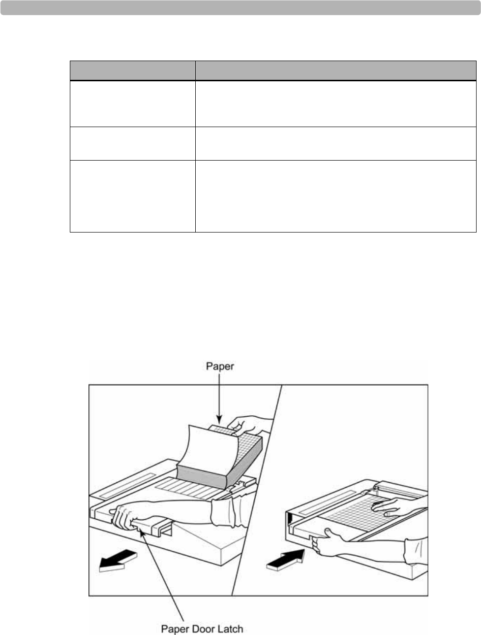
ST80i Thermal Printer
ST80i Stress Test System Instructions for Use C-5
Loading the Thermal Printer Paper
To load the paper
1Remove the outer packaging from the paper pack.
2Facing the front of the unit, use the release latch on the left side and slide the paper tray
cover to the left.
Table C-2 Input and Output descriptions
Feature Description
AC Power The ST80i thermal printer operates on 120/240 VAC at
50/60 Hz. Power is supplied to the thermal writer as soon as
the AC power cord is connected to an AC power outlet.
Power On Indicator This indicator will illuminate in green when AC power is
applied.
Hard Copy Printout The ST80i thermal printer uses 8 1/2 in x 11 in
(21 cm x 27.9 cm) sheets of z-folded, thermal sensitive
paper with cue marks. Printing speeds are 10, 25, and
50 mm per second. Dot density is eight dots per millimeter
or 203.2 dpi.

Configuring and Using the Printer
C-6 ST80i Stress Test System Instructions for Use
3Place the pack of thermal paper into the paper tray such that the grid side of the paper is up
when it is pulled over the paper tray cover.
The paper cue mark (a small black rectangle) should be in the lower left corner.
4Manually advance one page of paper beyond the closure point of the writer.
Make sure the paper lays on the black roller evenly within the channel of the paper door.
5Slide the writer cover to the right until the cover latches in a locked position.
You will hear a sharp click when the door is properly latched.
6Push the form-feed button to align the cue mark and prepare the paper for printing.
Setting Up the Thermal Printer
To connect the ST80i thermal printer
1Connect the AC power cord to the AC connector (B) on the printer and to an AC power
outlet.
2Connect one end of the crossover network cable to the network connector (D) on the
ST80i thermal printer and the other end to the PCI card connector on the back of the ST80i
PC, as shown in Figure C-3, below.
ASerial connector. Not used. BAC connector (for power cord)
CAC fuses DIntegrated network (LAN) connector

About the Supported LaserJet Printers
ST80i Stress Test System Instructions for Use C-7
Figure C-3 Connecting the thermal printer to the ST80i PC
About the Supported LaserJet Printers
ST80i also supports the use of the HP 4250 LaserJet, HP P2055, and HP P4014 PCL5 printers
using drivers for the Windows 7 operating system.
It is capable of printing reports, without a grid, at 35 ppm. It prints with a grid at
approximately 2 ppm.
NOTE The LaserJet printer must be a local printer, connected directly to the ST80i test system if it will be
used during testing. It cannot be a network printer, as connection to the network is disabled during a
test.
For details about the printers, refer to the HP website (www.hp.com) or to the printer
documentation.

Configuring and Using the Printer
C-8 ST80i Stress Test System Instructions for Use

D
D-1
Appendix AOrdering Options and Parts
This appendix describes the parts and options available for the ST80i Stress Test System.
This appendix provides the following information:
Supplies and Ordering Information. . . . . . . . . . . . . . . . . . . . . . . . . . . . . . . . . D-1
Optional Parts and Accessories . . . . . . . . . . . . . . . . . . . . . . . . . . . . . . . . D-1
Support Parts. . . . . . . . . . . . . . . . . . . . . . . . . . . . . . . . . . . . . . . . . . . . . . . D-3
Supplies and Ordering Information
The part numbers for all supplies for the ST80i system are listed in this section.
All supplies may be ordered on the web at:
http://shop.medical.philips.com
Ordering Options and Parts
D-2 ST80i Stess Test System Instructions for Use
Use the part numbers listed in the following tables for reference to ensure that the correct
supplies are ordered.
Optional Parts and Accessories
For more information on accessories or to place an order, contact the nearest Philips Response
Center. See “Philips Healthcare Customer Care Solution Center” on page A-8.
For available support parts (which can only be ordered by Philips personnel), see “Support
Parts” on page D-3.
Support Parts
For more information on accessories or to place an order, contact the nearest Philips Response
Center. See “Philips Healthcare Customer Care Solution Center” on page A-8.
The parts listed in the following tables can only be ordered by Philips personnel.
Part Number Description
Lead Set Supplies
989803180121 Leadset, 12L AAMI, Grabbers
989803180131 Leadset, 12L IEC, Grabbers
989803180141 Leadset, 12L AAMI, Snaps
989803180151 Leadset, 12L IEC, Snaps
989803180161 Leadset Long, 12L AAMI, Grabbers
989803180171 Leadset Long, 12L IEC, Grabbers
989803180181 Leadset Long, 12L AAMI, Snaps
40493E Adult Foam ECG Electrode, Disposable
Exchange Part
Number New Assembly Part
Number Item
453564350261 453564277261 STRS ST80i Wireless PIM - AAMI
453564350251 453564277271 STRS ST80i Wireless PIM - IEC
453564350271 453564305221 STRS ST80i Advanced Input
Module - AIM
453564032511 453564236991 STRS, ANT, AIM Antenna
453564350281 453564305231 STRS ST80i Thermal Printer
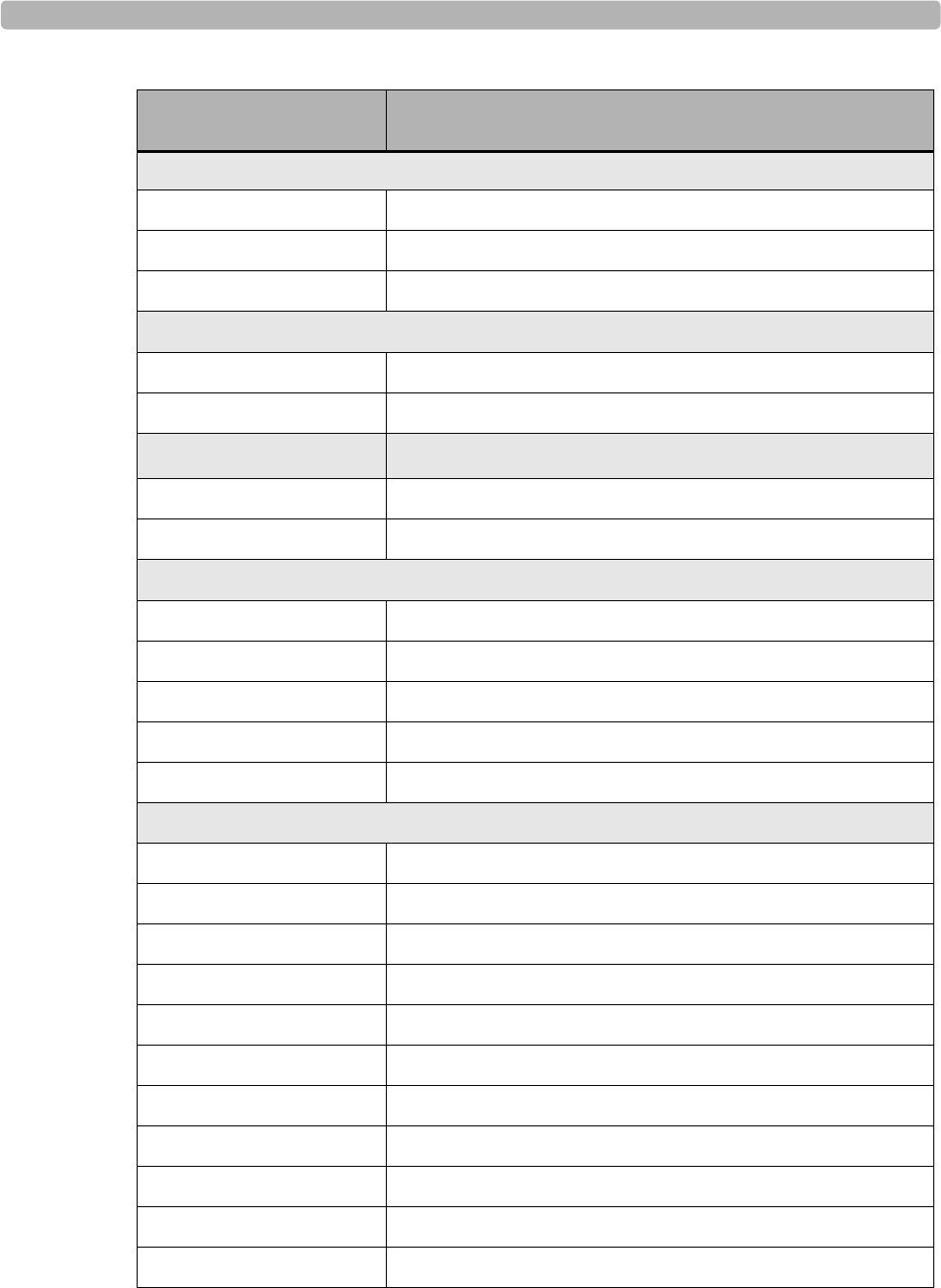
Supplies and Ordering Information
ST80i Stess Test System Instructions for Use D-3
New Assembly Part
Number Item
PIM
453564237251 STRS MECHASY Battery Door Assy
453564236601 PIM holder
453564236591 STRS, PIM Belt
AIM
453564312961 STRS, AIM Box Mounting Bracket
453564236761 STRS, CBL, AIM Analog Out
USB
453564096291 USB Cable AIM to PC 1m
453564336341 USB Cable Printer to PC 1.8m
Printer Accessories and Thermal Printer Paper
453564048431 PW, PL, Metric Spacer, A4 paper
Thermal PrinterPaper
Power Cords
8120-1351 CBL AC POWER CORD 2 METER OPTION 900
8120-1689 CBL AC POWER CORD 2 METER OPTION 902
8120-2961 CMS CBL EXT GND ASSY(Crocodile clip)
8120-4211 CBL AC POWER CORD 2 METER OPTION 917
8120-4475 CBL AC POWER CORD 2 METER OPTION 901
8120-4933 CBL OPT-912 16-AWG 3-COND
8120-5182 CBL AC POWER CORD 2 METER OPTION 919
8120-6869 CBL AC POWER CORD 2 METER OPTION 920
8120-6978 CBL PWR-CORD-921 18-AWG 3-COND
8120-8376 CBL AC POWER CORD 2.2 METER OPTION 922
8120-5429 CBL AC 3 WIRE POWER CORD

Ordering Options and Parts
D-4 ST80i Stess Test System Instructions for Use
Trolley Parts
453564237601 ST80i isolation transformer. - 240V
453564237591 ST80i isolation transformer. - 120V
453564334341 FUSE 6.30A 250V IEC
453564334331 FUSE 3.15A 250V IEC
453564315971 LAMP Trolley 220V
453564315961 STRS LAMP Trolley 120V
453564334151 STRS CASTER Roll Stand 4" TENTE
453564334161 STRS CASTER Roll Stand 4" TENTE Locking
453564334901 STRS PLAST Trolley Base Cover
453564334981 STRS PLAST Trolley Column Rear Cover
453564335001 STRS PLAST Trolley Wall Channel Cover
453564334881 STRS MET Basket Paper Catch
453564336361 Desk Light Power cord
453564336311 USB to RS232 Serial Adapter
453564334931 STRS PLAST Trolley Drawer Carriage
453564334941 STRS PLAST Trolley Basket Holder
453564334951 STRS PLAST Trolley Mushroom Mount
453564334961 STRS PLAST Trolley Cable Cover
453564334791 STRS MET Trolley Storage Shelf
453564334801 STRS MET Trolley Paper Basket
453564335281 STRS Utility Basket
453564335261 STRS MET Laser Printer Shelf W/Bracket
453564335261 STRS MET Top Shelf Utility Hook
453564335271 STRS 1/2 work surface cover
453564334881 STRS Basket Paper Catch
453564337261 STRS Full cover work surface
New Assembly Part
Number Item
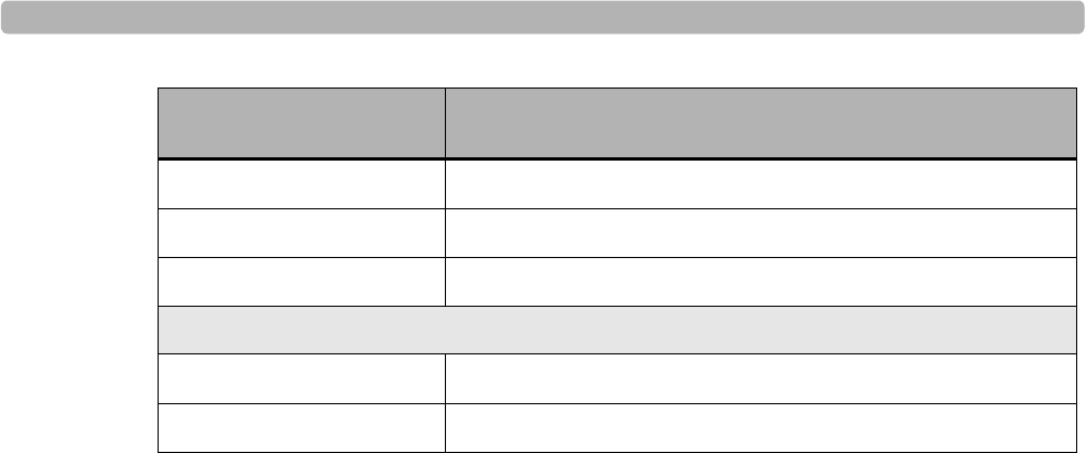
Supplies and Ordering Information
ST80i Stess Test System Instructions for Use D-5
453564312961 STRS, AIM Box Mounting Bracket
453564335301 STRS Tango Arm Kit
453564335271 STRS Utility Hook
Software and Documentation
453564xxxxxx ST80i software CD
453564xxxxxx ST80i Documentation and Training CD
New Assembly Part
Number Item

Ordering Options and Parts
D-6 ST80i Stess Test System Instructions for Use

E
E-1
Appendix ASpecifications and Requirements
For details about setting up the system, see the ST80i Installation and Configuration Guide.
NOTE No user serviceable parts are inside. ANY modification of this device may alter defibrillator
protection. Any modification to any part of this device is to be performed only by qualified service
personnel. See also Chapter 5, “Maintaining the ST80i System”
This appendix provides the following information:
ST80i System Requirements . . . . . . . . . . . . . . . . . . . . . . . . . . . . . . . . . . . . . . .E-1
Specifications . . . . . . . . . . . . . . . . . . . . . . . . . . . . . . . . . . . . . . . . . . . . . . . . . .E-4
ST80i System Specifications . . . . . . . . . . . . . . . . . . . . . . . . . . . . . . . . . . .E-4
Medical Isolation Transformer Specifications . . . . . . . . . . . . . . . . . . . . . .E-6
ST80i Thermal Printer Specifications . . . . . . . . . . . . . . . . . . . . . . . . . . . .E-7
Supported Treadmills and Ergometers . . . . . . . . . . . . . . . . . . . . . . . . . . . . . . .E-8
Electromagnetic Compatibility (EMC) - To be finalized . . . . . . . . . . . . . . . . .E-8
Accessories and Cables Warning . . . . . . . . . . . . . . . . . . . . . . . . . . . . . . . .E-9
Guidance and Manufacturer’s Declaration: Electromagnetic Emissions.E-10
Guidance and Manufacturer’s Declaration: Electromagnetic Immunity .E-11
Recommended Separation Distances . . . . . . . . . . . . . . . . . . . . . . . . . . . .E-15
ST80i System Requirements
For the ST80i System to function properly, the following minimum specified system
requirements must be met.
TIP For the latest information on supported systems and requirements, visit the Philips website listed
below and select the Cardiology product line. The ST80i documentation and Technical Data Sheet
containing the latest specifications are available online.
www.medical.philips.com/goto/productdocumentation
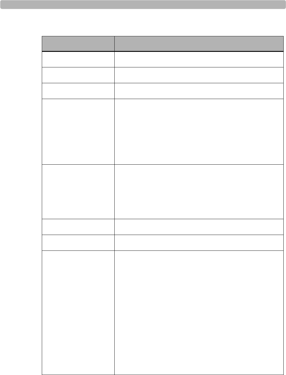
Specifications and Requirements
E-2 ST80i Stress Test System Instructions for Use
Table E-1 Minimum ST80i system requirements
Component Minimum Hardware/Software Specifications
Processor Intel® Core™ i5-2400S (2.50 GHz, 6 MB cache, 4 cores)
Memory 4GB 1333 MHz DDR3 SDRAM
Hard disk No less than 160 GB SATA; 7200 RPM
Display The lowest resolution for each layout:
For 4:3, the lowest resolution is 1024 x768
For 16:9, the lowest resolution is 1280 x720
NOTE The display used with ST80i must meet UL/IEC 60950-1
Safety Standards for Information Technology Equipment.
Network The PC’s LAN interface should support IEEE 802.3
compliant 10M/100M/1000M Base-T(X) Ethernet
connections
LAN connection for laser printer is required
Optional LAN card for networking capabilities
CD-ROM drive CD-RW/DVD combo drive
Operating system Microsoft Windows 7 Professional
External Connectivity The system must have the following external connections:
RS232-USB bridge
100-240V 50/60Hz AC Power input
Display output
LAN
Minimum of five (5) USB ports.
ST80i may use an external USB hub to extend the USB
ports for easier user access, if required.
Speaker output
Printer port.
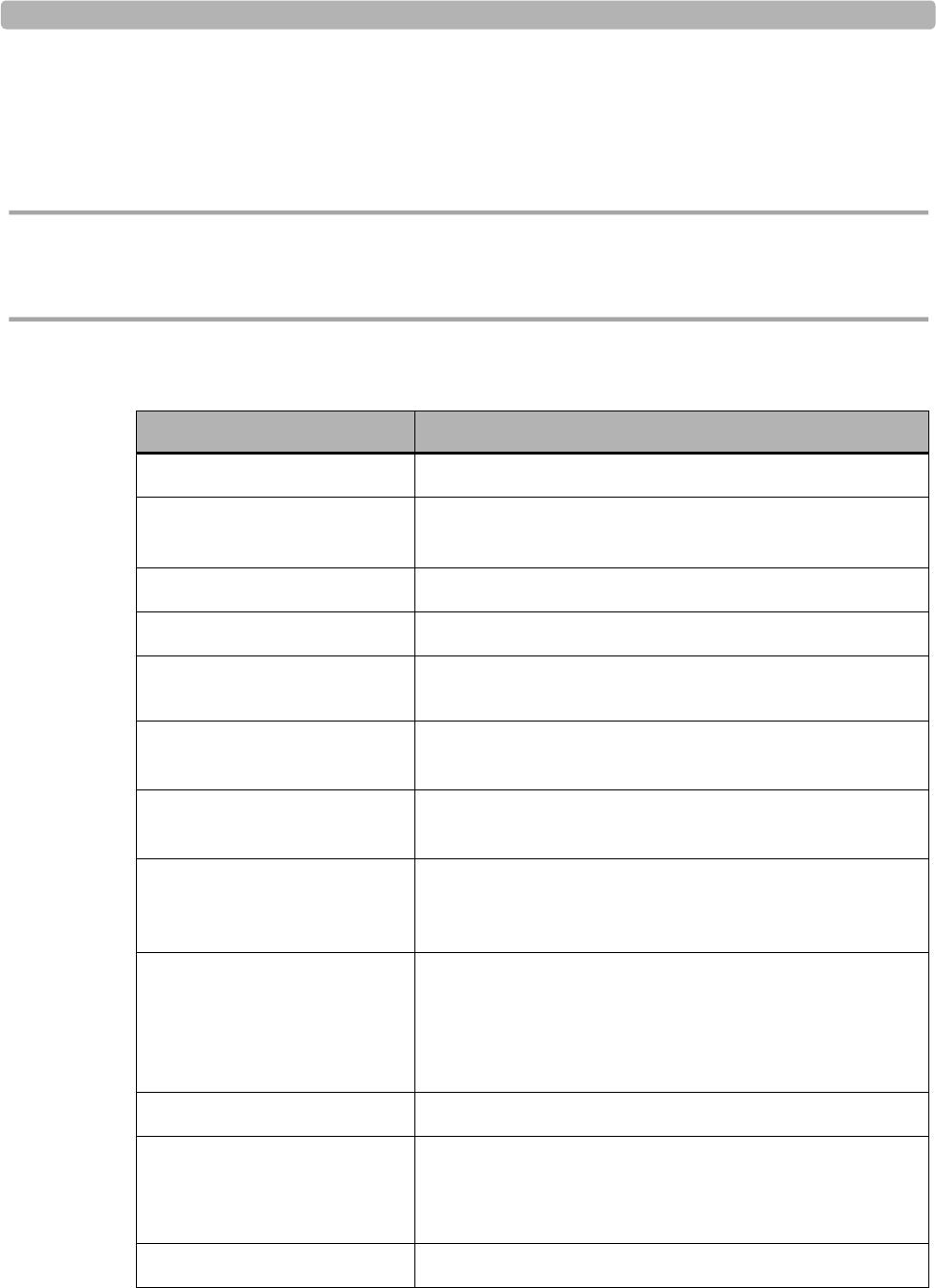
Specifications
ST80i Stress Test System Instructions for Use E-3
Specifications
ST80i System Specifications
CAUTION The system does not contain user-serviceable parts. Any modification of this device may alter
defibrillator protection. Only qualified service personnel are authorized to modify any part of this
device.
Table E-2 ST80i system specifications
Function Specifications
Instrument type Exercise stress test system
Isolation transformer power Rated Input/Output Voltage: 120 VAC @ 50/60 Hz
Rated Input/Output Voltage: 240 VAC @ 50/60 Hz
Input Channels Simultaneous acquisition of all 12 leads
Standard leads I, II, III, aVR, aVL, aVF, V1, V2, V3, V4, V5, V6
Exercise equipment
interface Digital serial interface to treadmill or ergometer
Automatic blood pressure
measurement option Supports optional SpO2 and motion tolerant NIBP
modules.
Network option Optional Network interface for data transfer and printing
across your local network
Remote Review Workstation
option Optional Remote Review Workstation for review, printing,
and editing of patient text data acquired from the ST80i
system.
Display format Sweep speed. Two supported speeds: 25 mm/s and 50 mm/s
Size Range from 19" to 24"
Resolution. The lowest resolution for each layout:
For 4:3, the lowest resolution is 1024x768
For 16:9, the lowest resolution is 1280x720
ECG input Simultaneous input from all 12 leads
Input impedance Meets the requirements of ANSI/AAMI EC-11
Defibrillator protected when used with specified
patient cable
Input dynamic range Meets the requirements of ANSI/AAMI EC-11
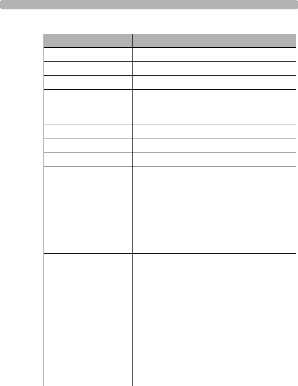
Specifications and Requirements
E-4 ST80i Stress Test System Instructions for Use
Common mode rejection Meets the requirements of ANSI/AAMI EC-11
Patient leakage current Meets the requirements of ANSI/AAMI ES-1
Overall system error Meets the requirements of ANSI/AAMI EC-11
Frequency response Meets the requirements of ANSI/AAMI EC-11
Methods A and D were used to establish frequency
response.
Digital sampling rate 1,000 sample/sec/channel, used for recording and analysis
Recording technique Thermal array printer, 200 dots per inch (dpi)
Paper type Thermal, perforated, 8.5 in x 11 in Z-fold
Recorder Recording speeds. 5mm/sec, 10mm/sec, 25mm/sec,
50mm/sec
Channels. User can select any channels to print on
thermal printer
Sensitivity. 2.5mm/mV, 5mm/mV, 10mm/mV,
20mm/mV
Gain 2.5mm/mV, 5mm/mV, 10mm/mV,
20mm/mV
Data acquisition Direct connect or wireless connection
using ST80i wireless patient interface
module
Max Power Rate
Consumption Computer. 180 W
Monitor. 50 W
Thermal printer. 60 W
NIBP/SPO2 module 45 W
19"/24" Display 50 W
Desk light 5.5 W
USB Hub TBD
Isolation Transformer. 600 Volt Amps
Treadmill TBD
Device Classification Class 1, Type CF defibrillator-proof applied parts
Data acquisition Direct connect or wireless connection using ST80i digital
transmitter
External output TTL and analog output
Table E-2 ST80i system specifications
Function Specifications
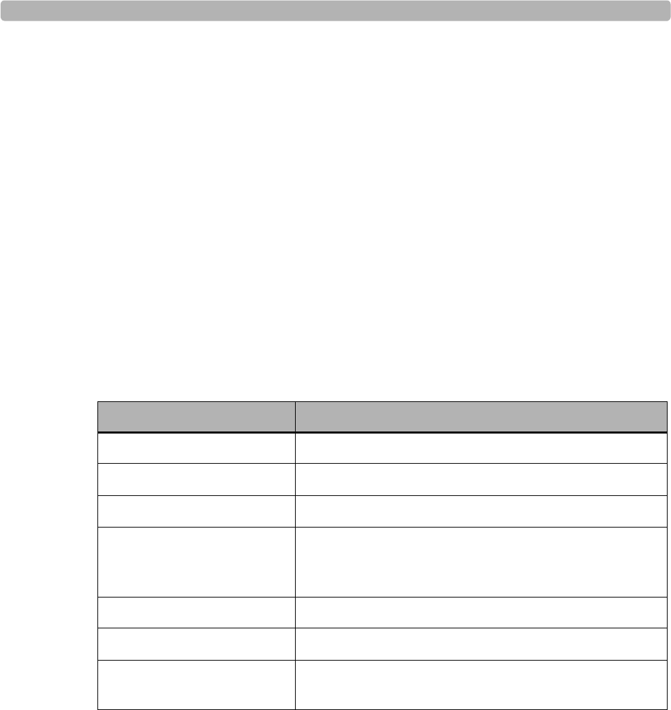
Specifications
ST80i Stress Test System Instructions for Use E-5
Medical Isolation Transformer Specifications
The medical isolation transformers used with the ST80i system meet the following
specifications: UL 60601-1, CSA C22.2 601.1, EN60601.1, CE (LVD), ROHS compliant.
Figure E-1 Medical isolation transformer provided with ST80i
Table E-3 Medical isolation transformer specifications
Function Specifications
Frequency 50/60 Hz
Output ratings 120V 600VA or 240V 600VA
Weight 26.5 lb (12 Kg)
Dimensions Height. 4.08" (103.5mm)
Width. 6.55" (166.4mm)
Depth. 10.5" (266.7mm)
REF: 1404-102 Input 120VAC – 6.3AT
REF: 1404-003 Input 230VAC – 3.15AT.
Fuses Use agency-approved fuses only, 250V.
The transformer has an internal thermal resettable fuse.
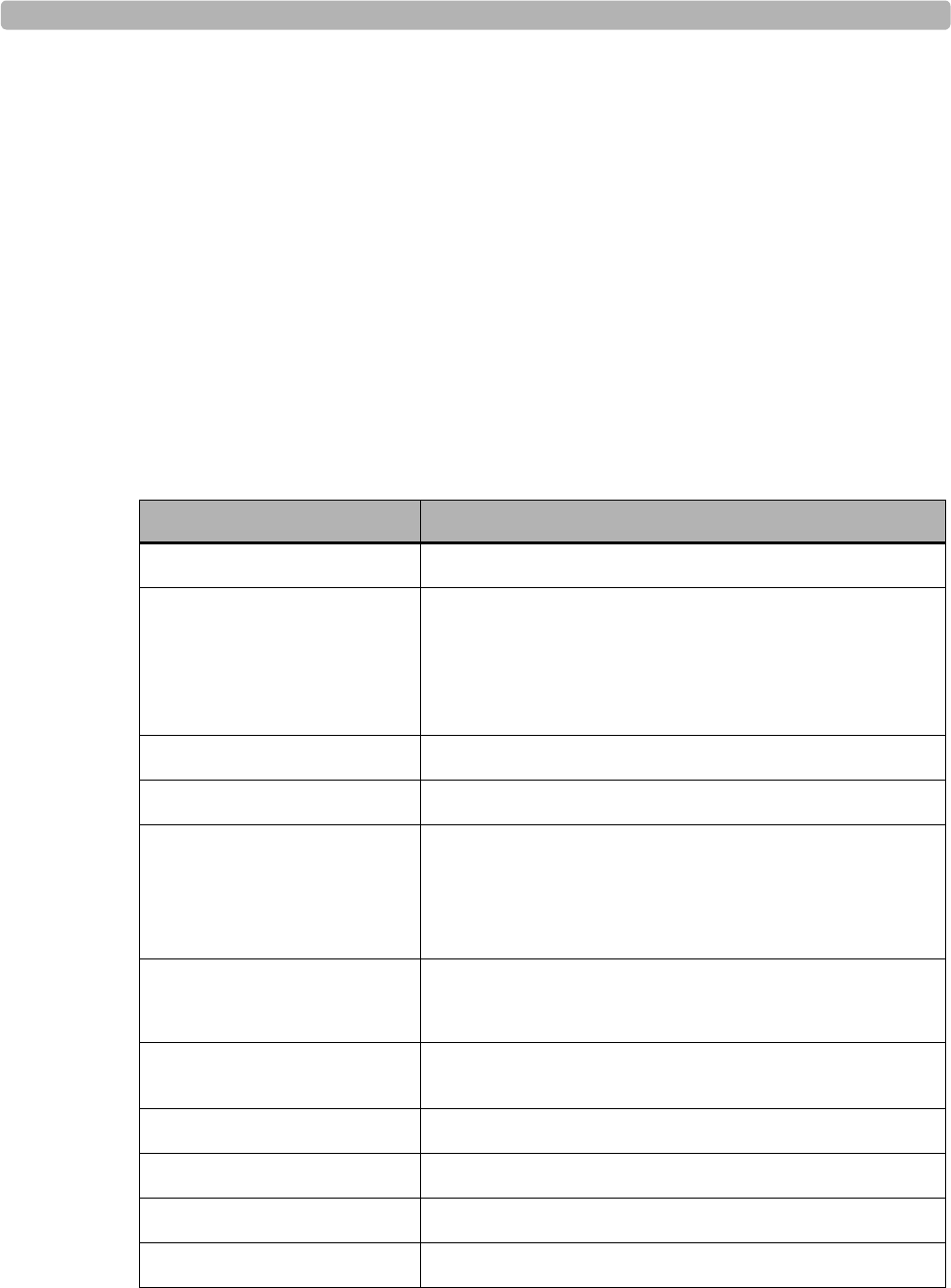
Specifications and Requirements
E-6 ST80i Stress Test System Instructions for Use
ST80i Thermal Printer Specifications
Table E-4 ST80i thermal printer specification
Feature Specification
Instrument type Thermal printer
Paper type Supports the use of the following paper types supplied as
z-fold in packages of 100 and 200 sheets:
A-size Normal, Anti-fade, and Easy Tear
A4-size Normal, Anti-fade, thin, and Easy Tear
Recording technique Computer controlled, thermal dot array
Print-head width 8.5 inches (216 mm)
Print-head resolution Vertical: 200 dots/inch, vertical
Horizontal:
5, 10, and 25 mm/sec: 500 dots/inch
50 mm/sec: 250 dots/inch
Printer speeds 25 or 50 mm/sec for AUTO report
5, 10, 25, or 50 mm/sec for rhythm print
External ports and data
interfaces USB 2.0-compliant, type-B socket connector
Chassis leakage current Meet or exceed requirements of ANSI/AAMI EC11
Power 100-240 VAC at 50/60 Hz
Weight 9 pounds
Dimensions H x W x D 8 cm x 48 cm x 30 cm maximum
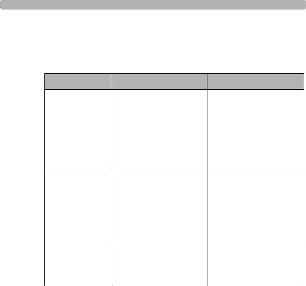
Supported Treadmills and Ergometers
ST80i Stress Test System Instructions for Use E-7
Supported Treadmills and Ergometers
The ST80i Stress Test System supports the following treadmills and ergometers.
Electromagnetic Compatibility (EMC)
Electromagnetic compatibility with surrounding devices should be assessed when using the
ST80i Stress Test System and optional Thermal Printer.
An electronic device can either generate or receive electromagnetic interference. Testing for
electromagnetic compatibility (EMC) has been performed on the ST80i Stress Test System
and optional Thermal Printer according to the international standard for EMC for medical
devices (IEC 60601-1-2 Edition 2). This IEC standard has been adopted in Europe as the
European Norm (EN 60601-1-2 Edition 2).
The ST80i Stress Test System and optional Thermal Printer should not be used adjacent to, or
stacked on top of, other equipment. If the ST80i Stress Exercise Testing System and optional
Thermal Printer must be used adjacent to or stacked on top of other equipment, verify that the
Table E-5 Supported Treadmills and Ergometers
Equipment Manufacturer Models
Treadmills Trackmaster Treadmills
by Full Vision
FVX328
FVX328C
FVX328CP
TMX425
TMX425C
TMX425CP
Ergometers Ergoline Ergometer Type er800S
Ergometer Type er900
Ergometer Type er900EL
Ergoselect Reha
Ergoselect 600
(recumbentbike, ergometer)
Lode Angio
Corival
Excalibur Sport

Specifications and Requirements
E-8 ST80i Stress Test System Instructions for Use
ST80i Stress Test System and optional Thermal Printer operates in an acceptable manner in
the configuration in which it will be used.
Fixed, portable, and mobile radio frequency communications equipment can affect the
performance of medical equipment. See Table E-9, “Recommended Separation Distances,” on
page E-14 for recommended separation distances between the radio equipment and the ST80i
Stress Exercise Testing System and optional Thermal Printer.
Accessories and Cables Warning
The use of accessories and cables other than those specified in Appendix F, “Ordering Options
and Parts” may result in increased emissions or decreased immunity of the ST80i Stress Test
System and optional Thermal Printer.
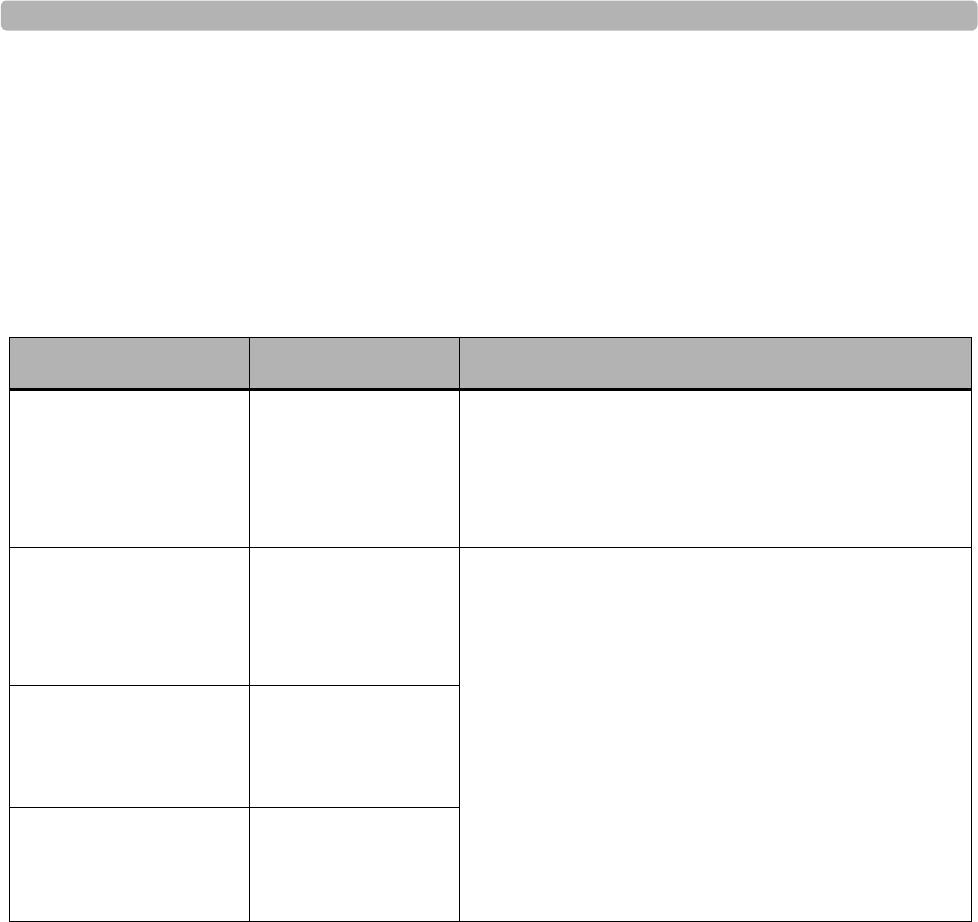
Electromagnetic Compatibility (EMC)
ST80i Stress Test System Instructions for Use E-9
Guidance and Manufacturer’s Declaration:
Electromagnetic Emissions
The ST80i Stress Test System and optional Thermal Printer are intended for use in the
electromagnetic environment specified in the table below. The customer or the user of the
ST80i Stress Test System and optional Thermal Printer should assure that it is used in such an
environment.
Table E-6 Guidance and Manufacturer’s Declaration: Electromagnetic Emissions
Emissions Test Compliance Electromagnetic Environment Guidance
RF Emissions CISPR 11 Group 1
30 MHz to
1000 MHz
The ST80i Stress Test System and optional Thermal
Printer use RF energy only for its internal function.
Therefore, its RF emissions are very low and not likely
to cause any interference in nearby electronic
equipment.
RF Emissions CISPR 11 Class B
150 kHz to 30 MHz
The ST80i Stress Test System and optional Thermal
Printer are suitable for use in all establishments other
than domestic and those directly connected to the public
low-voltage power supply network that supplies
buildings used for domestic purposes.
Note ST80i PIM and AIM are designed and certified to meet
CFR 47 FCC Part 15 and EN 301 489 for devices with
intentional transmitters.
Harmonic Emissions
IEC 61000-3-2 Complies
Voltage fluctuations/
flicker emissions
IEC 61000-3-3
Complies

Specifications and Requirements
E-10 ST80i Stress Test System Instructions for Use
Guidance and Manufacturer’s Declaration:
Electromagnetic Immunity
The ST80i Stress Test System and optional Thermal Printer are intended for use in the
electromagnetic environment specified in the following tables. The customer or the user of the
ST80i Stress Test System and optional Thermal Printer should assure that it is used in such an
environment.
Table E-7 Guidance and Manufacturer’s Declaration: Electromagnetic Immunity
Emissions Test Compliance Compliance Level Electromagnetic Environment
Guidance
Electrostatic
Discharge (ESD)
IEC 61000-4-2
+/- 6 kV contact
discharge
+/- 8 kV air
discharge
+/- 6 kV contact
discharge
+/- 8 kV air
discharge
Floors should be wood, concrete, or
ceramic tile. If floors are covered
with synthetic material, the relative
humidity should be at least 30%.
Electrical Fast
transient/burst
IEC 61000-4-4
+/- 2 kV for
power supply line
+/- 1 kV for input/
output
+/- 2 kV for power
supply line
+/- 1 kV for input/
output lines
Mains power quality should be that
of a typical commercial or hospital
environment.
Surge
IEC 61000-4-5
+/- 1 kV
differential mode
+/- 2 kV common
mode
+/- 1 kV differential
mode
+/- 2 kV common
mode
Mains power quality should be that
of a typical commercial or hospital
environment.
Voltage dips, short
interruptions and
voltage variations on
power supply input
lines
IEC 61000-4-11
<5% UT
(>95% dip in UT)
for 0.5 cycle
40% UT
(60% dip in UT)
for 5 cycles
70% UT
(30% dip in UT)
for 25 cycles
<5% UT
(>95% dip in UT)
for 5 sec
<5% UT
(>95% dip in UT)
for 0.5 cycle
40% UT
(60% dip in UT)
for 5 cycles
70% UT
(30% dip in UT)
for 25 cycles
Mains power quality should be that
of a typical commercial or hospital
environment. If the user of the ST80i
Stress Test System and optional
Thermal Printer requires continued
operation during power mains
interruptions, it is recommended that
the ST80i Stress Test System and
optional Thermal Printer be powered
from an uninterruptible power
supply or a battery.
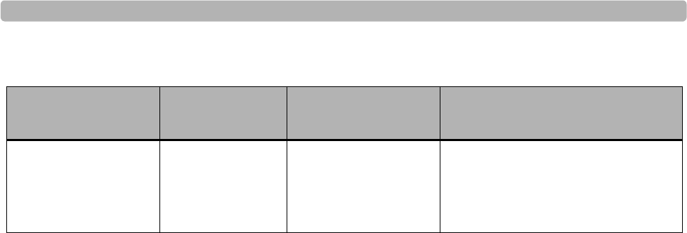
Electromagnetic Compatibility (EMC)
ST80i Stress Test System Instructions for Use E-11
NOTE UT is the AC mains voltage prior to application of the test level.
Power frequency
(50/60 Hz) magnetic
field immunity
3 A/m,
50 & 60 Hz 3 A/m
50 & 60 Hz Power frequency magnetic fields
should be at levels characteristic of a
typical location in a typical
commercial or hospital environment.
Table E-7 Guidance and Manufacturer’s Declaration: Electromagnetic Immunity
Emissions Test Compliance Compliance Level Electromagnetic Environment
Guidance
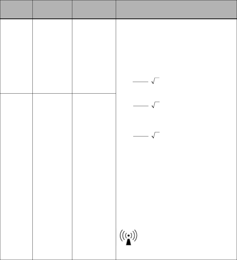
Table E-8 Guidance and Manufacturer’s Declaration: Electromagnetic Immunity
Emissions
Test IEC 60601
Test Level Compliance
Level Electromagnetic Environment Guidance
Conducted
Immunity,
Induced RF
IEC
61000-4-6
3Vrms,
0.15 MHz to
80 MHz, @
10 Hz AM
3Vrms,
0.15 MHz to
80 MHz, @
10 Hz AM
Portable and mobile RF communications equipment
should be used no closer to any part of the ST80i
Stress Test System and optional Thermal Printer,
including cables, than the recommended separation
distance calculated from the equation applicable to
the frequency of the transmitter.
Recommended separation distance:
Where P is the maximum output power rating of the
transmitter in watts (W) according to the transmitter
manufacturer and d is the recommended separation
distance in meters (m).
Field strengths from fixed RF transmitters, as
determined by an electromagnetic site surveya, should
be less than the compliance level in each frequency
rangeb.
Interference may occur in the vicinity of equipment
marked with the following symbol:
Radiated RF
IEC
61000-4-3
General Test:
3V/m, 80 MHz
to 2.5 GHz @
10 Hz AM
Digital Radio
Test: 3V/m
80% AM @
1kHz ,
800 MHz to
960 MHz ,
1.4 GHz to
2.5 GHz
General Test:
3V/m, 80 MHz
to 2.5 GHz @
10 Hz AM
Digital Radio
Test: 3V/m
80% AM @
1kHz , 800 MHz
to 960 MHz ,
1.4 GHz to
2.5 GHz
P
Vrms
d
=3
5.3
P
mV
d
=/3
5.3
80 MHz to 800 MHz
P
mV
d
=/3
7
800 MHz to 2.5 GHz
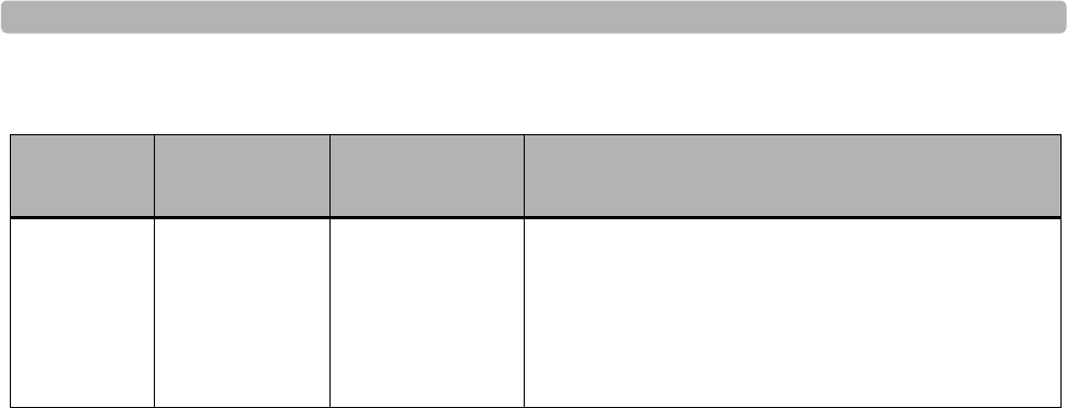
Electromagnetic Compatibility (EMC)
ST80i Stress Test System Instructions for Use E-13
a. Field strengths from fixed transmitters, such as base stations for radio (cellular/cordless) telephones and land
mobile radios, amateur radios, AM and FM radio broadcast and TV broadcast cannot be predicted
theoretically with accuracy. To assess the electromagnetic environment due to fixed RF transmitters, an
electromagnetic site survey should be considered. If the measured field strength in the location in which the
ST80i Stress Test System and optional Thermal Printer are used exceeds the applicable RF compliance level
above, the ST80i Stress Test System and optional Thermal Printer should be observed to verify normal
operation. If abnormal performance is observed, additional measures may be necessary, such as reorienting
or relocating the ST80i Stress Test System and optional Thermal Printer.
b. Over the frequency range 150 kHz to 80 MHz, field strengths should be less than [3] V/m.
Electro-
surgery
Interference
IEC
60601-2-25
100W & 300W
Cut/Coag, at
450 kHz ±
100 kHz.
100W & 300W
Cut/Coag, at
450 kHz ±
100 kHz.
Table E-8 Guidance and Manufacturer’s Declaration: Electromagnetic Immunity
Emissions
Test IEC 60601
Test Level Compliance
Level Electromagnetic Environment Guidance
Specifications and Requirements
E-14 ST80i Stress Test System Instructions for Use
Recommended Separation Distances
The ST80i Stress Test System and optional Thermal Printer are intended for use in the
electromagnetic environment in which radiated RF disturbances are controlled. The customer
or the user of the ST80i Stress Test System and optional Thermal Printer can help prevent
electromagnetic interference by maintaining a minimum distance between portable and mobile
RF communications equipment (transmitters) and the ST80i Stress Test System and optional
Thermal Printer as recommended below, according to the maximum output power of the
communications equipment.
NOTES For transmitters rated at a maximum output power not listed above, the recommended separation
distance d in meters (m) can be estimated using the equation applicable to the frequency of the
transmitter, where P is the maximum output power rating of the transmitter in watts (W)
according to the transmitter manufacturer.
At 800 MHz, the separation distance for the higher frequency range applies.
These guidelines may not apply in all situations. Electromagnetic propagation is affected by the
absorption and reflection from structures, objects, and people.
Table E-9 Recommended Separation Distances
Rated Maximum Output
Power of Transmitter (W) Separation Distance According to Frequency of
Transmitter (m)
150 KHz to 800 MHz 800 MHz to 2.5 GHz
0.01 0.1 m 0.2 m
0.1 0.4 m 0.7 m
1 1.2 m 2.3 m
10 4.0 m 7.0 m
100 12.0 m 23.0 m
Pd 2.1=
Pd 3.2=

Philips Medical Systems
3000 Minuteman Road
Andover, MA 01810 USA
Copyright © 2012
Koninklijke Philips Electronics N.V.
All rights are reserved.
ST80i Stress Test System
Instructions for Use
Printed in USA
453564XXXXXX
Edition 1
June 2012
*453564214311*
Authorized EU-representative:
Philips Medizin Systeme
Böblingen GmbH
Hewlett Packard Str. 2
71034 Böblingen
Germany