Philips Medical Systems North America WLANBV2 WLAN Module IEEE 802.11 a/b/g/n User Manual ait fm manual en 2012 03 02
Philips Medical Systems North America Co. WLAN Module IEEE 802.11 a/b/g/n ait fm manual en 2012 03 02
Contents
- 1. Installation Instructions
- 2. User Manual IntelliVue MP2
- 3. User Manual IntelliVue CL
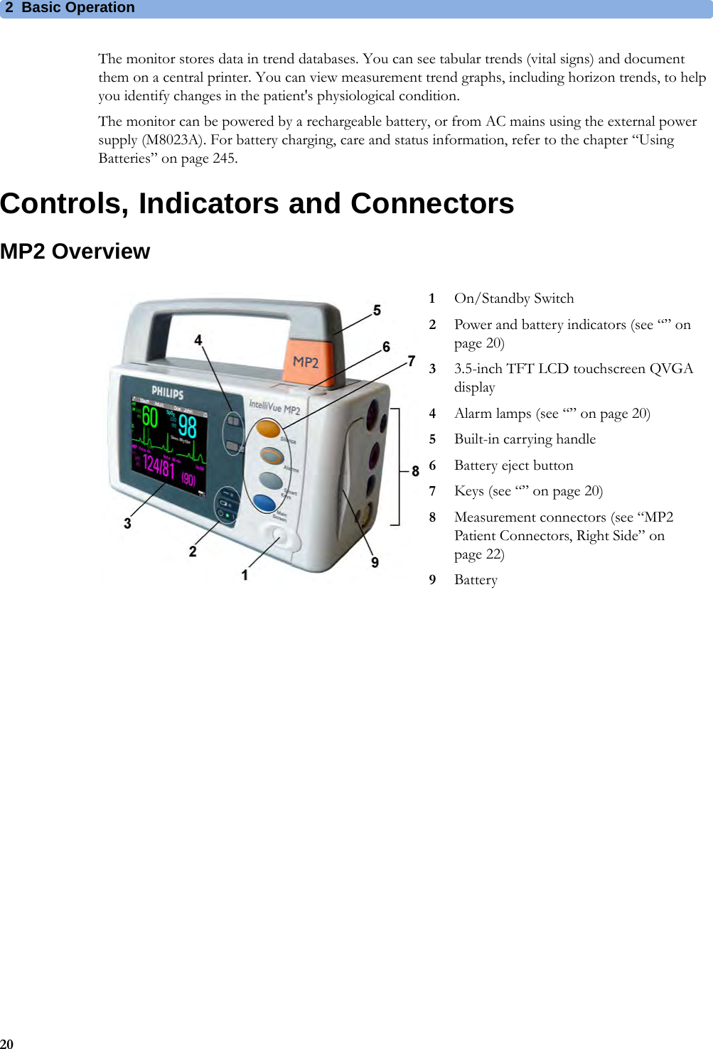
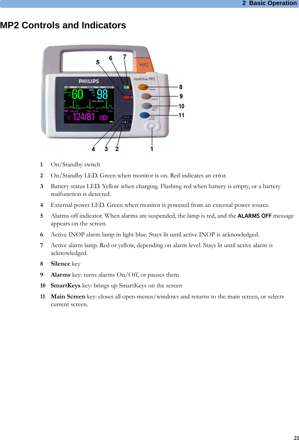
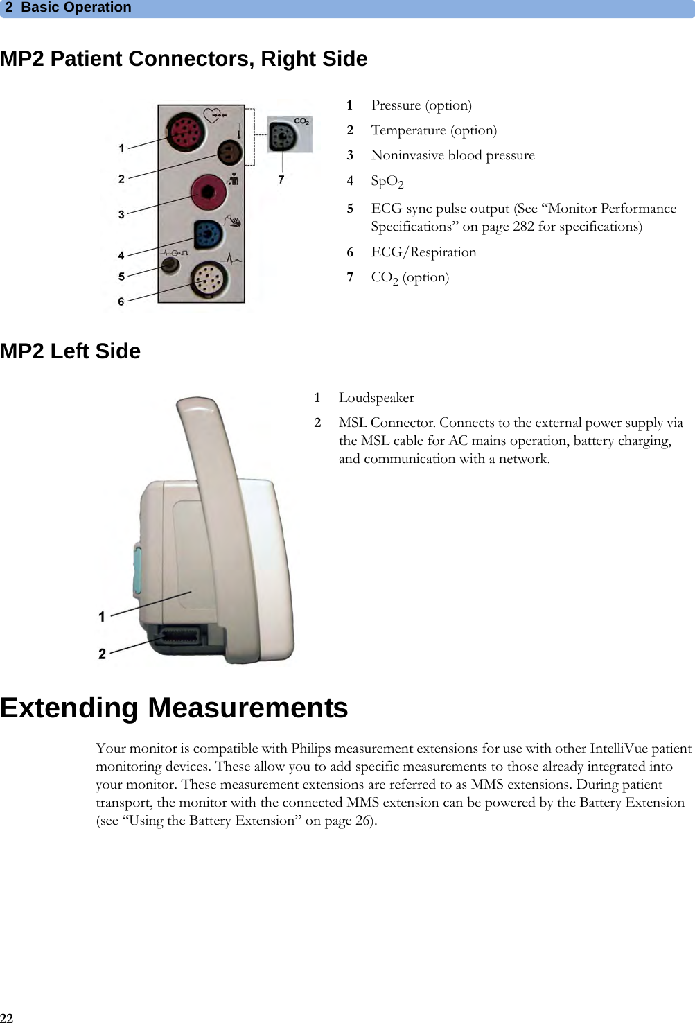
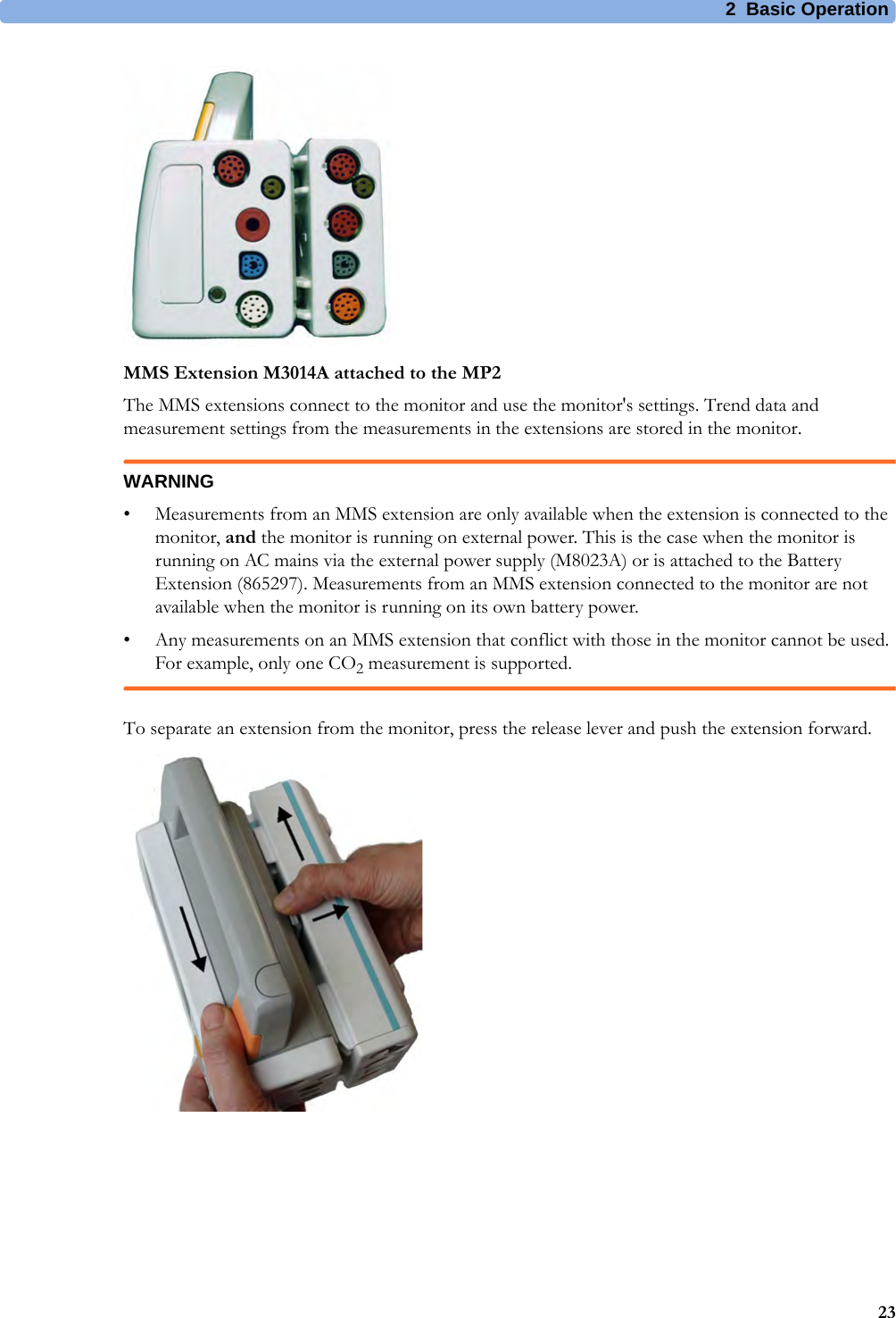
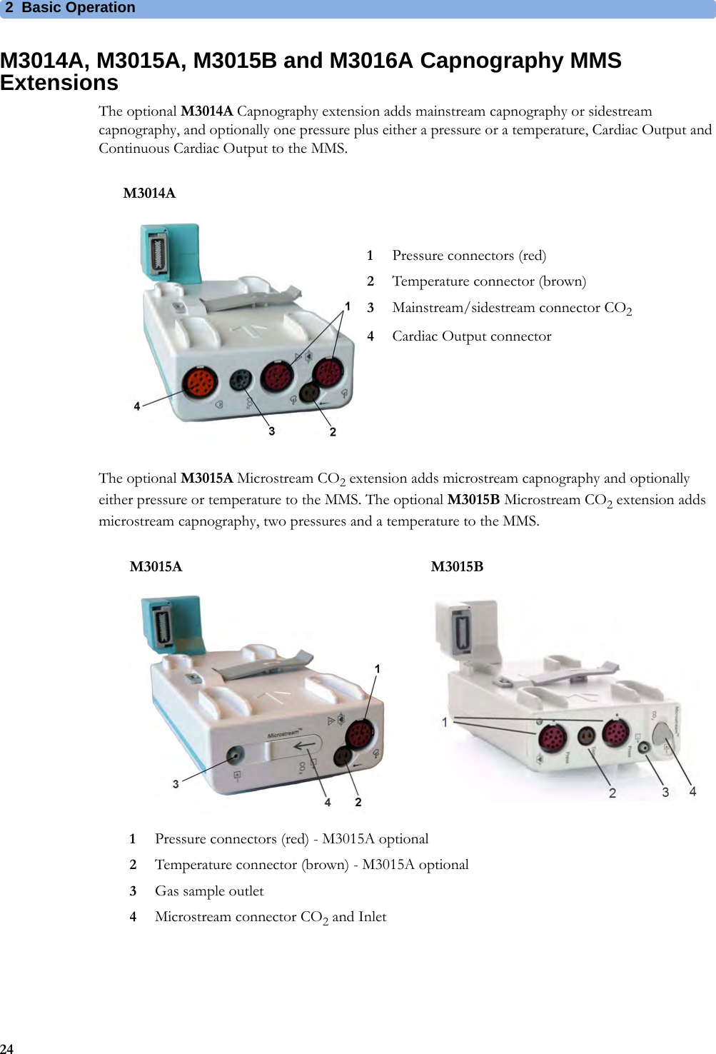
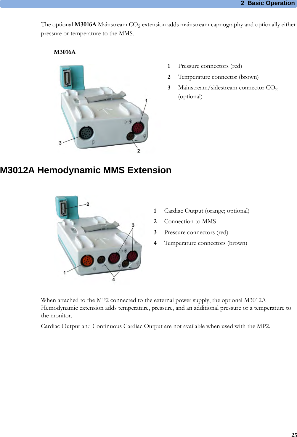
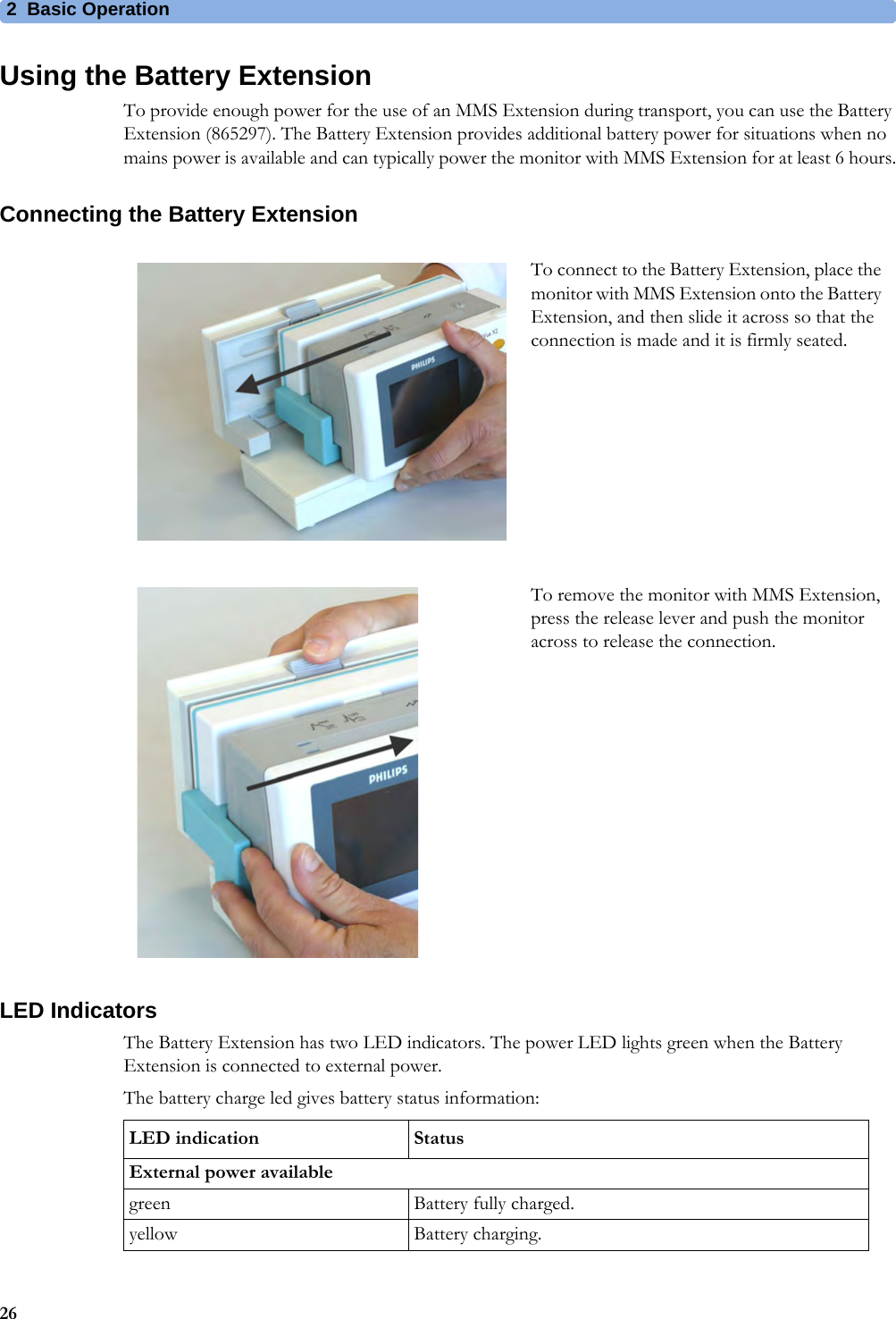
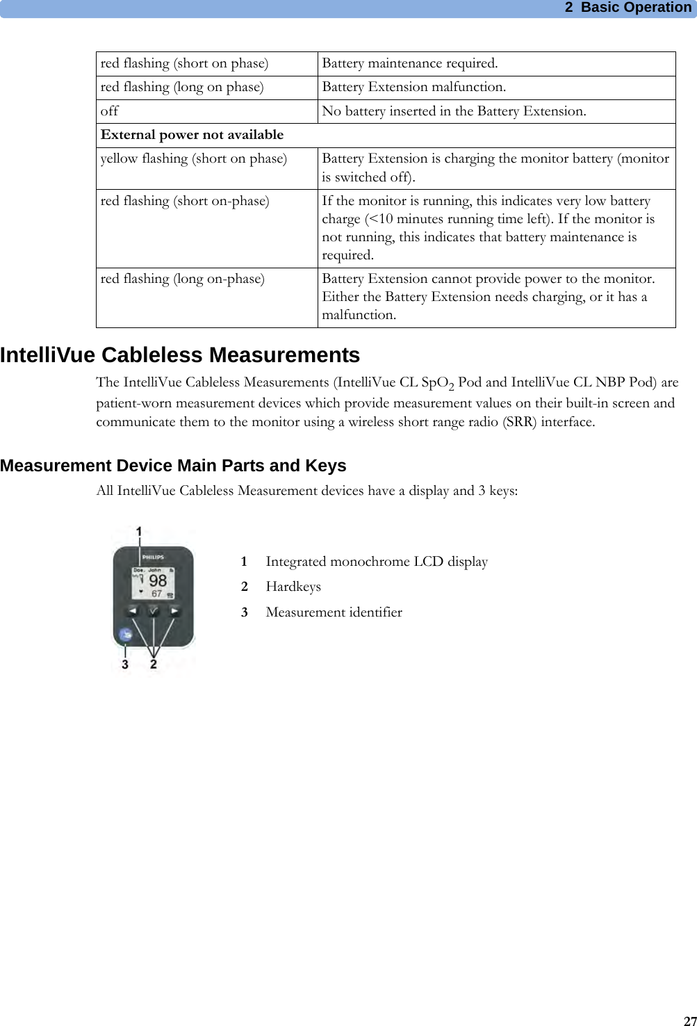
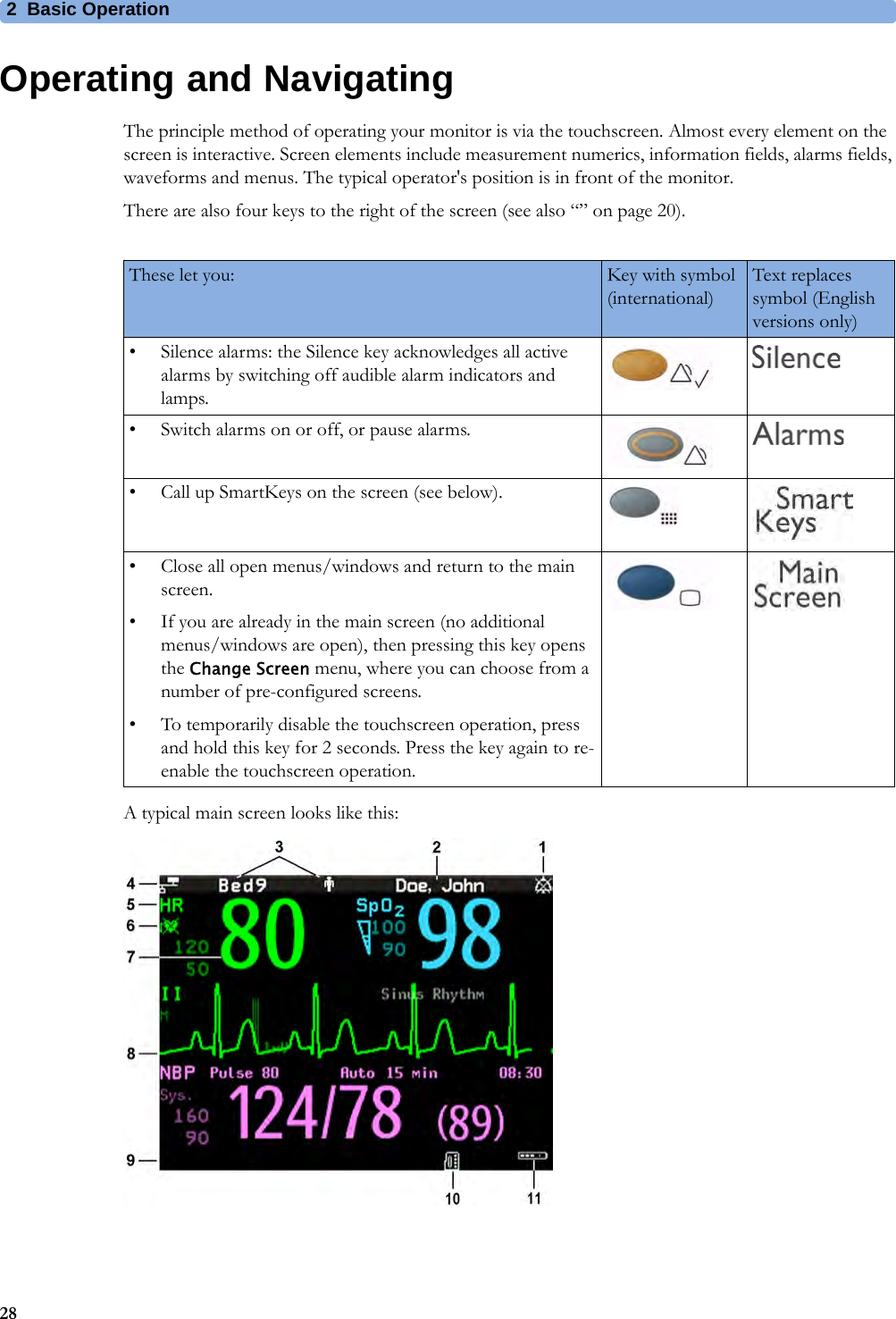
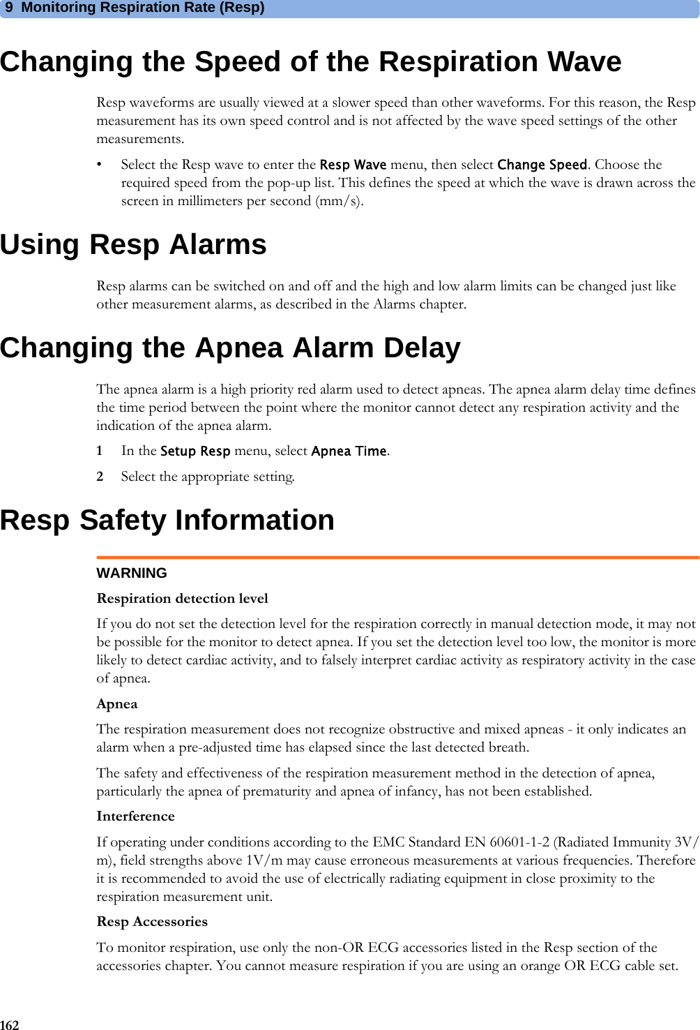
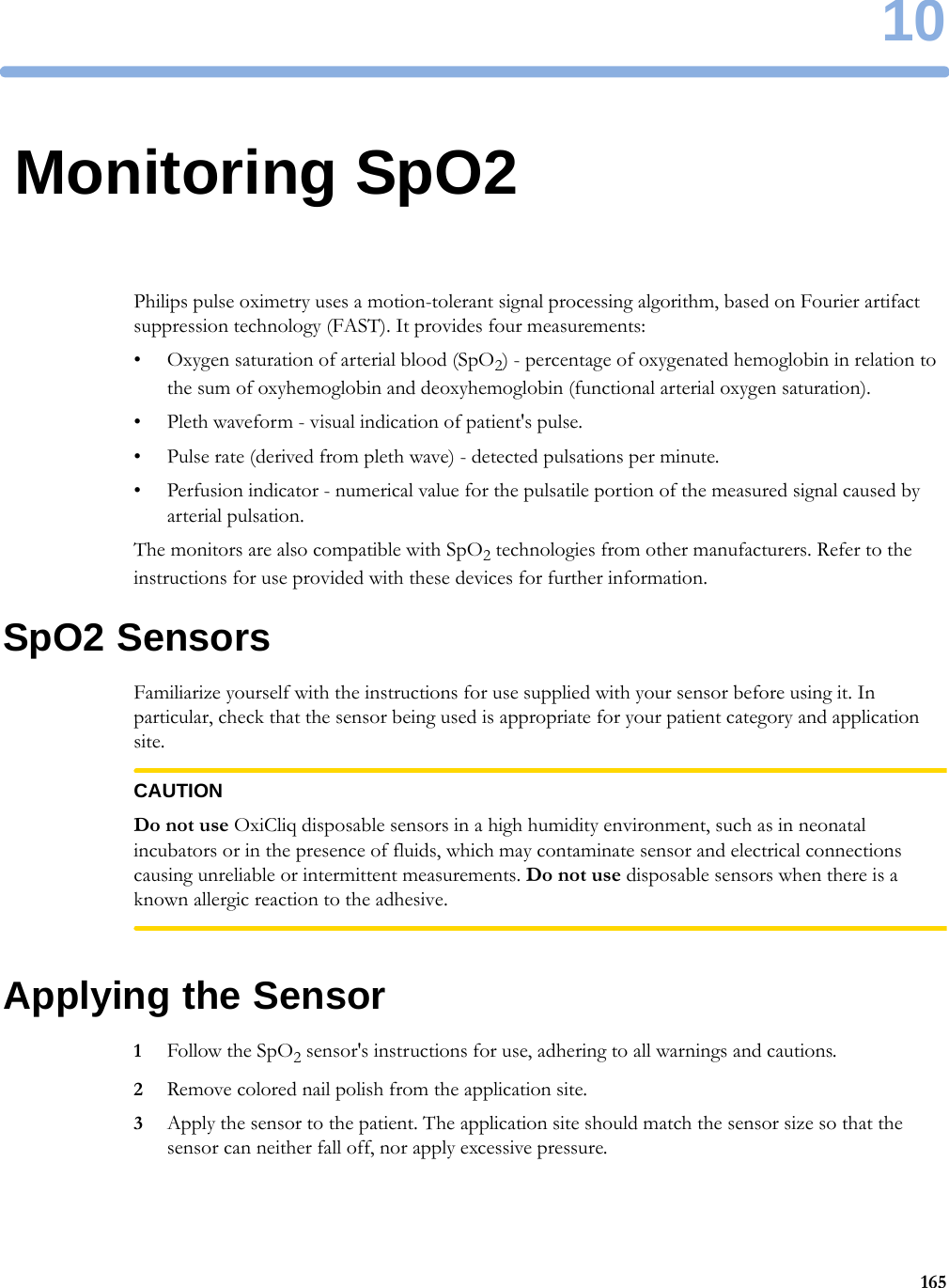
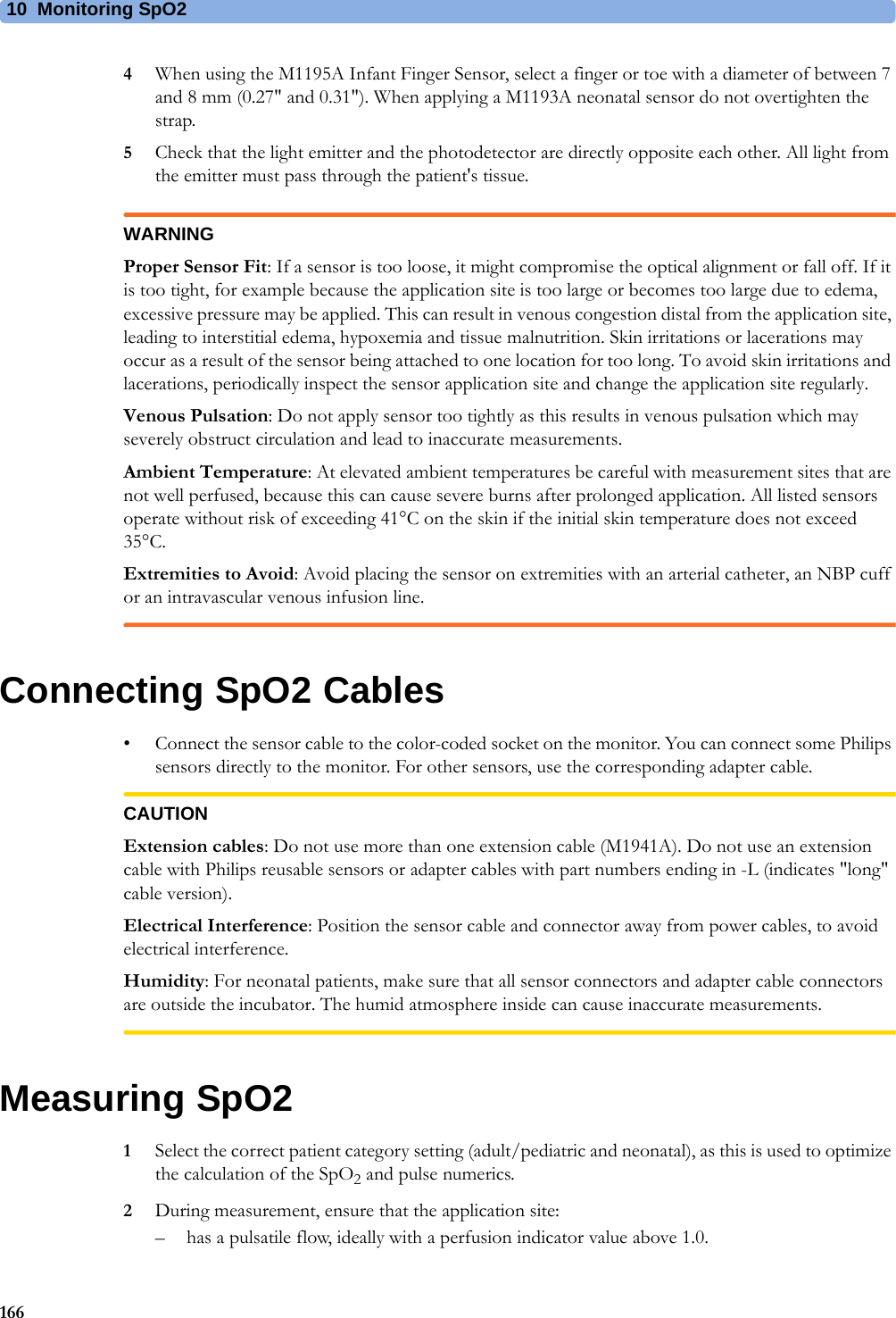
User Manual IntelliVue MP2
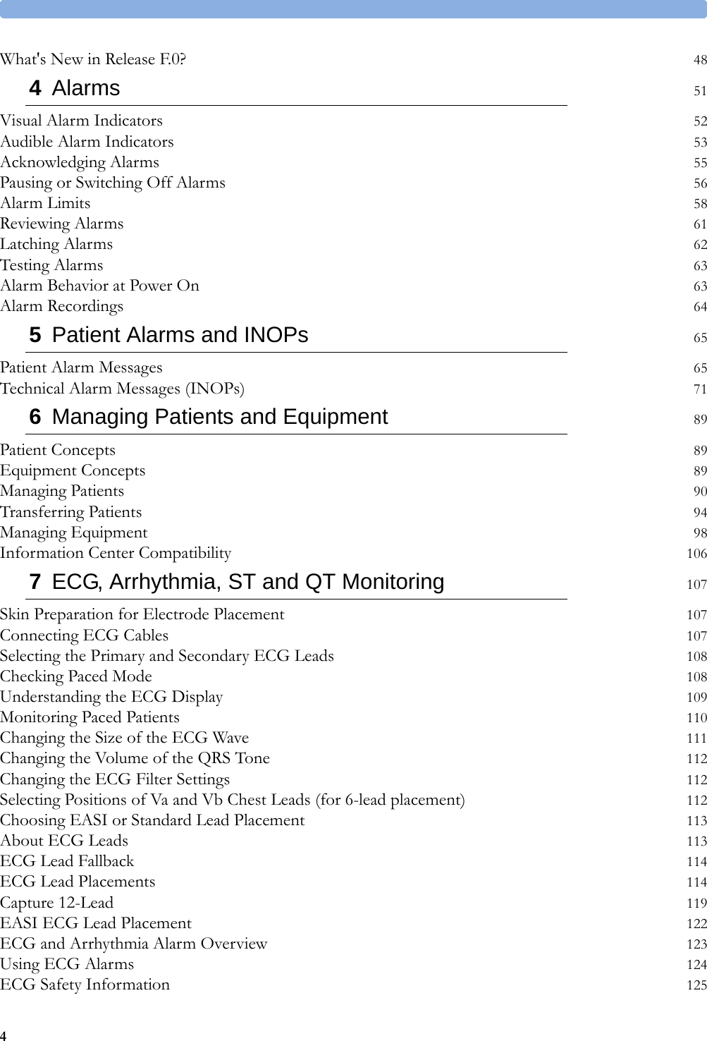
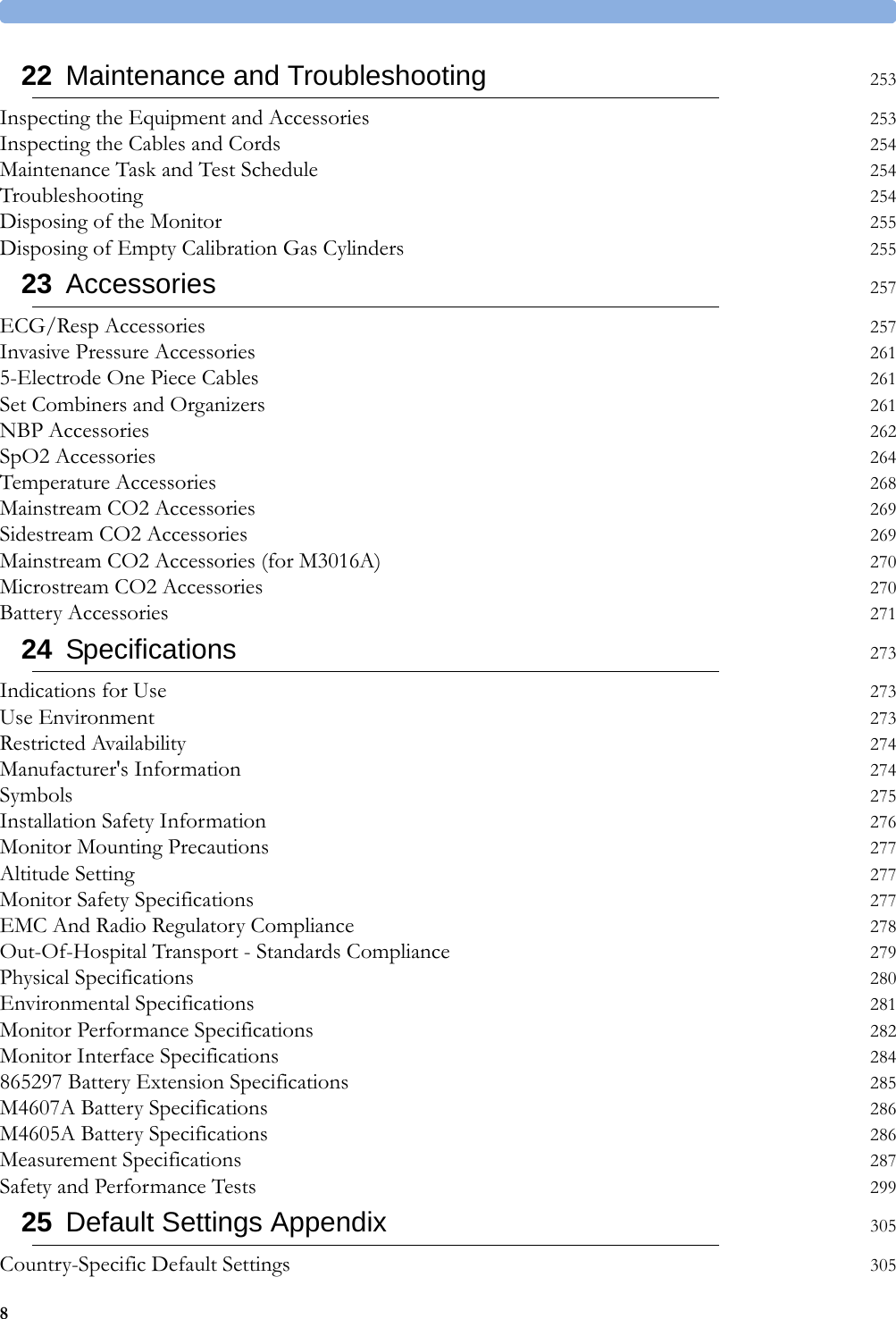

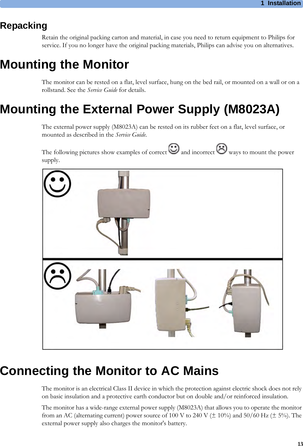
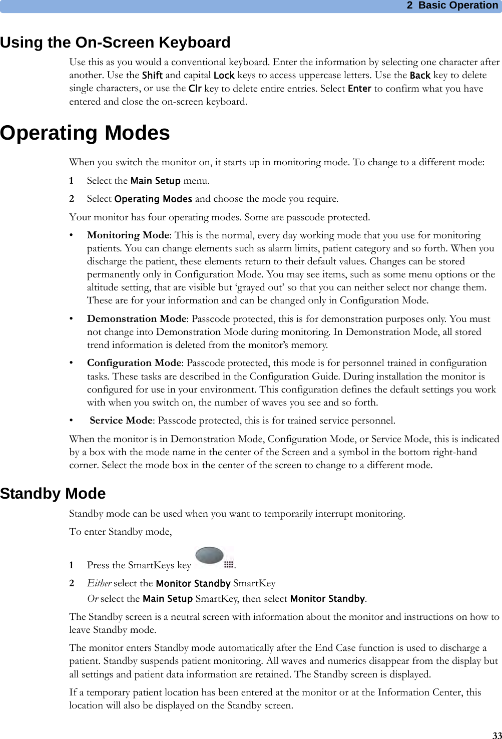
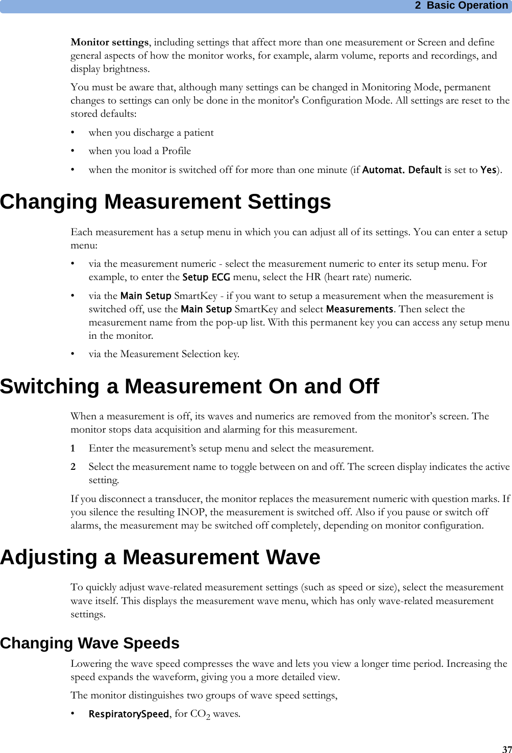
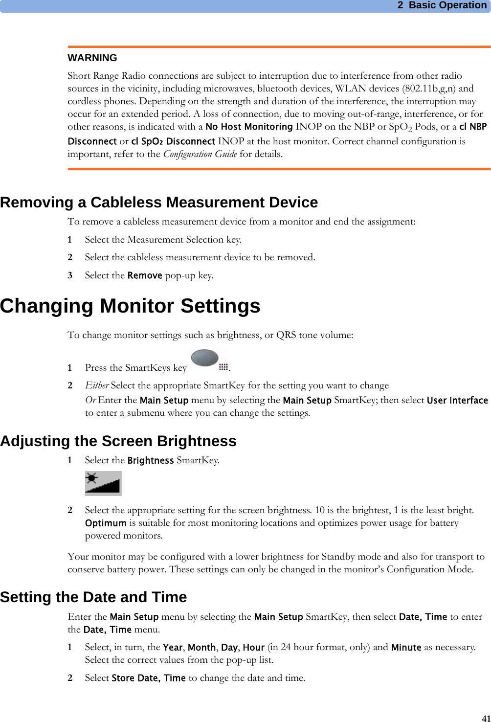
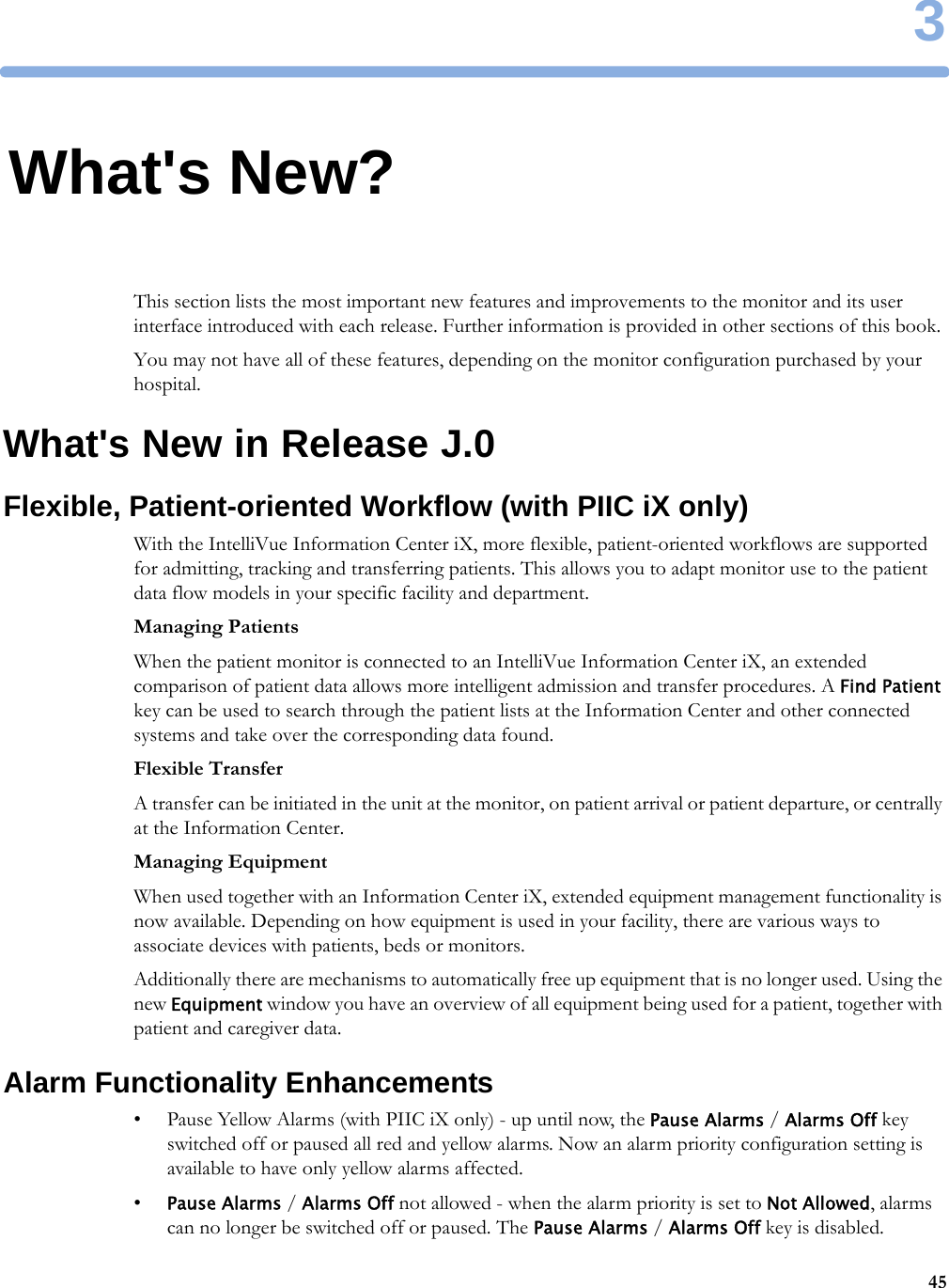


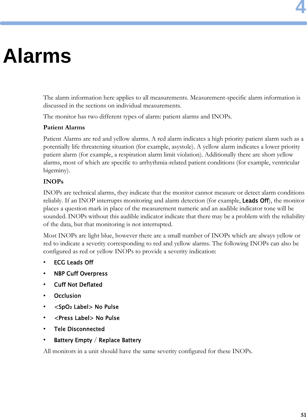
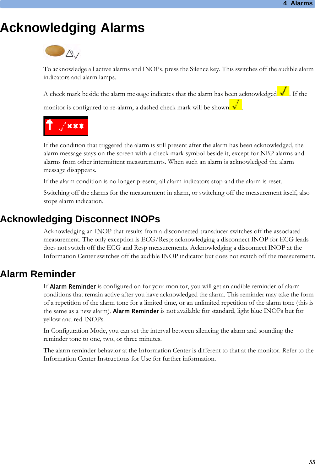
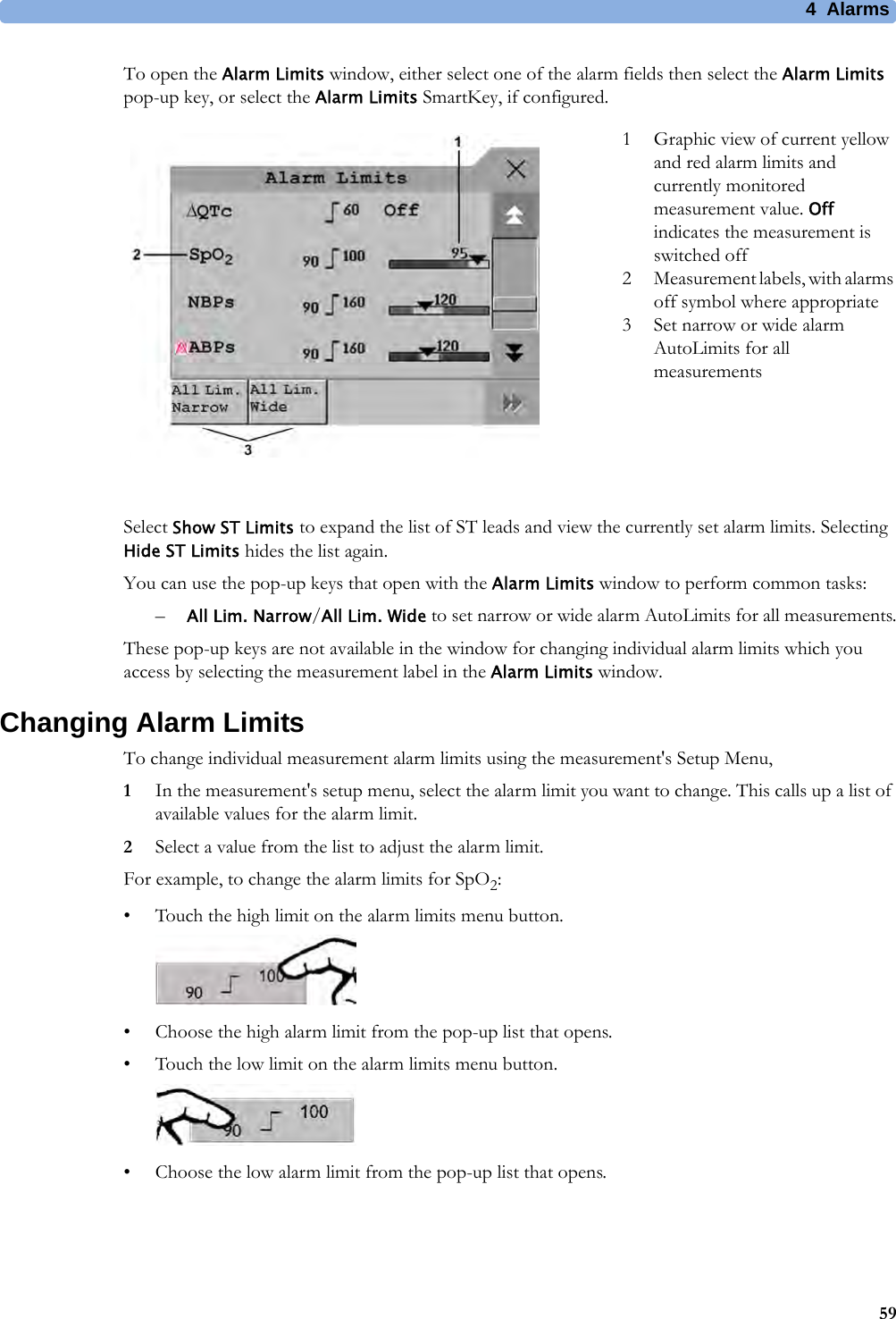
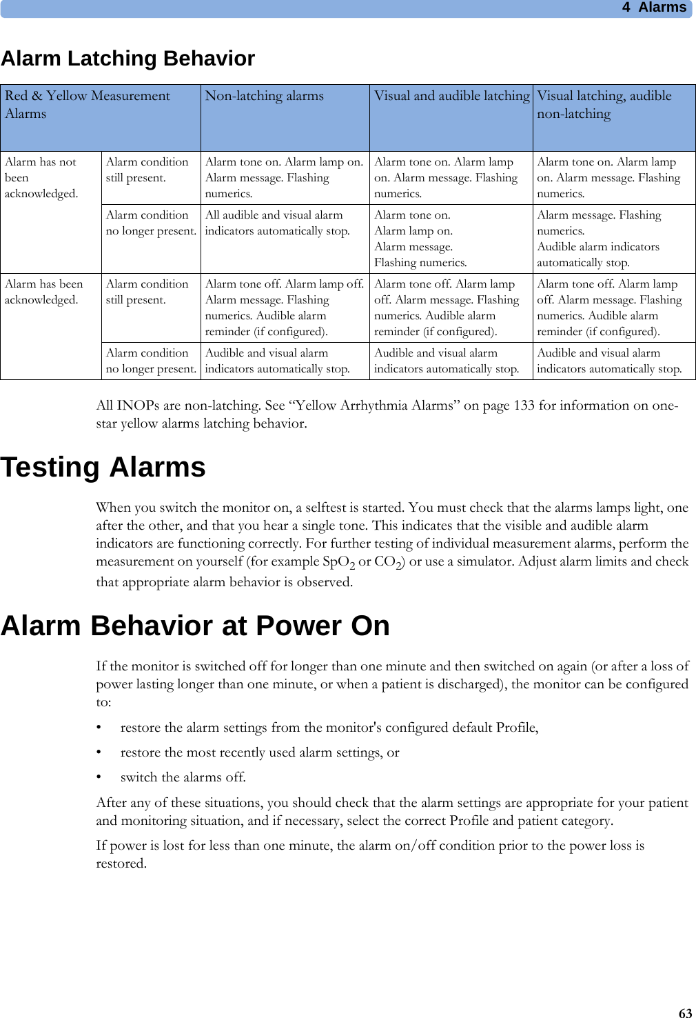
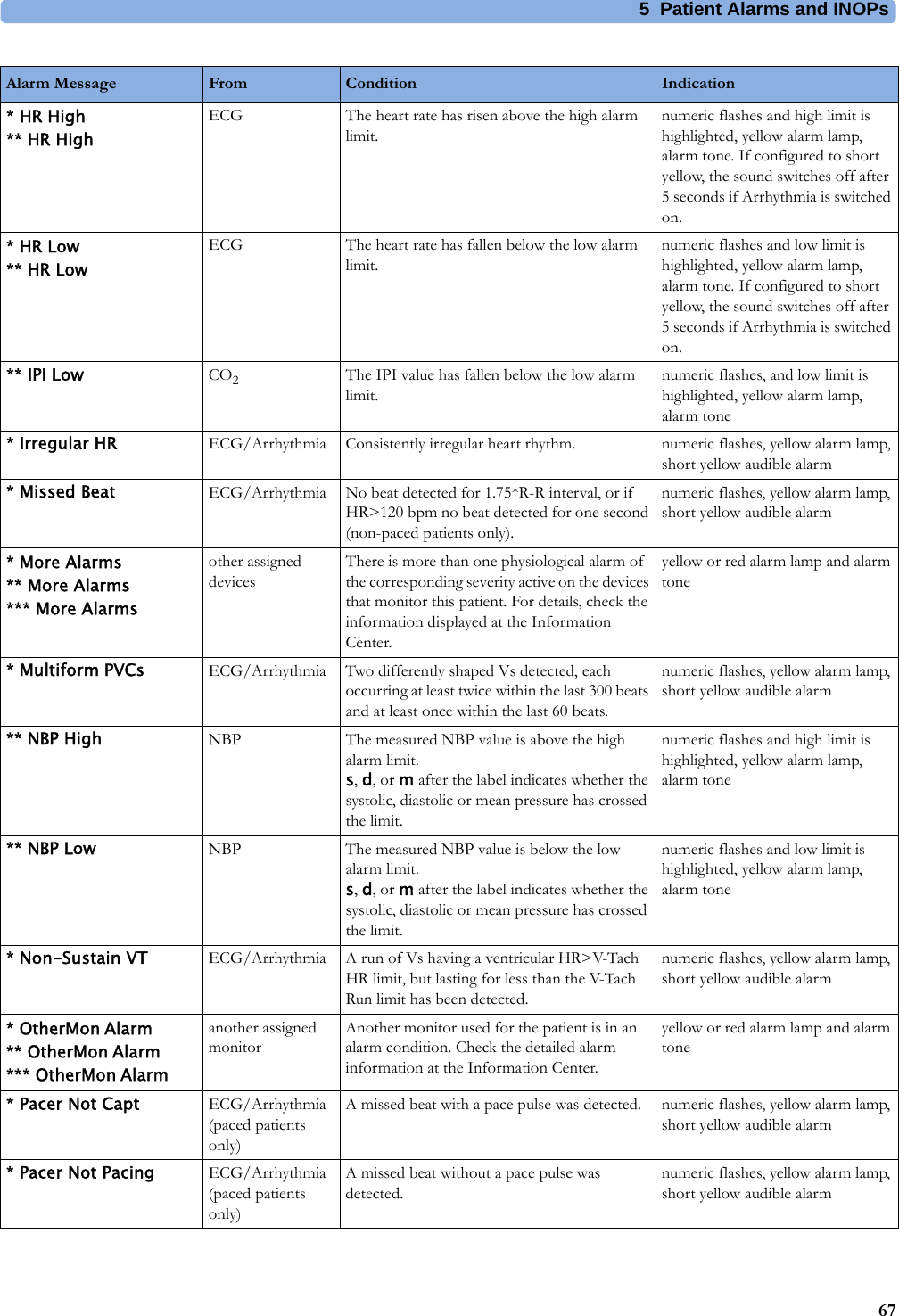
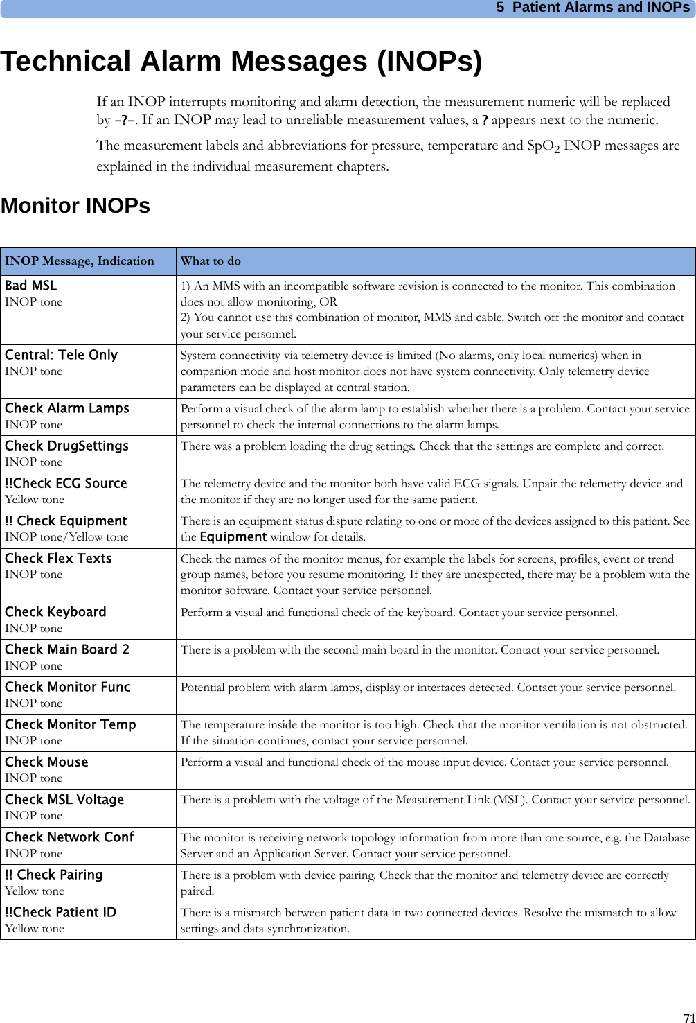
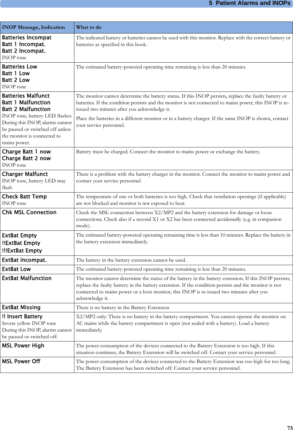
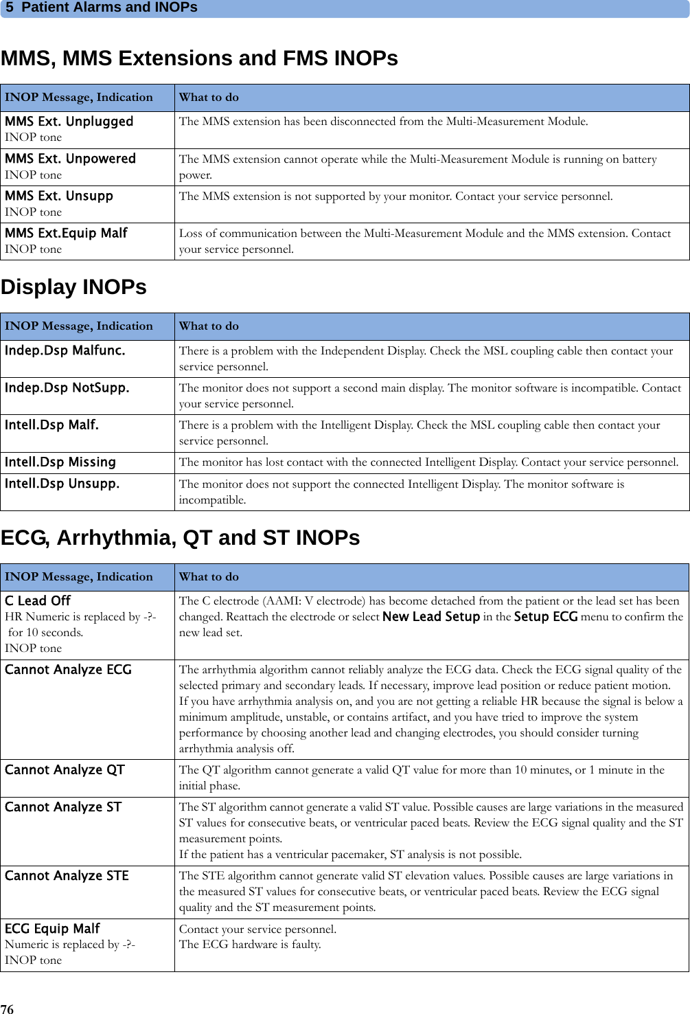
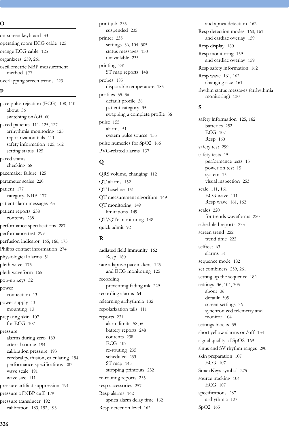
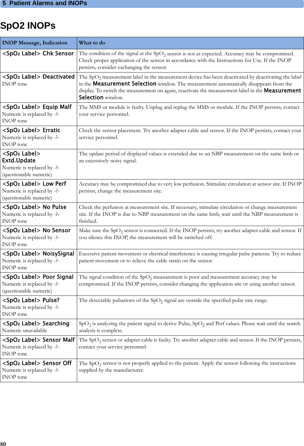
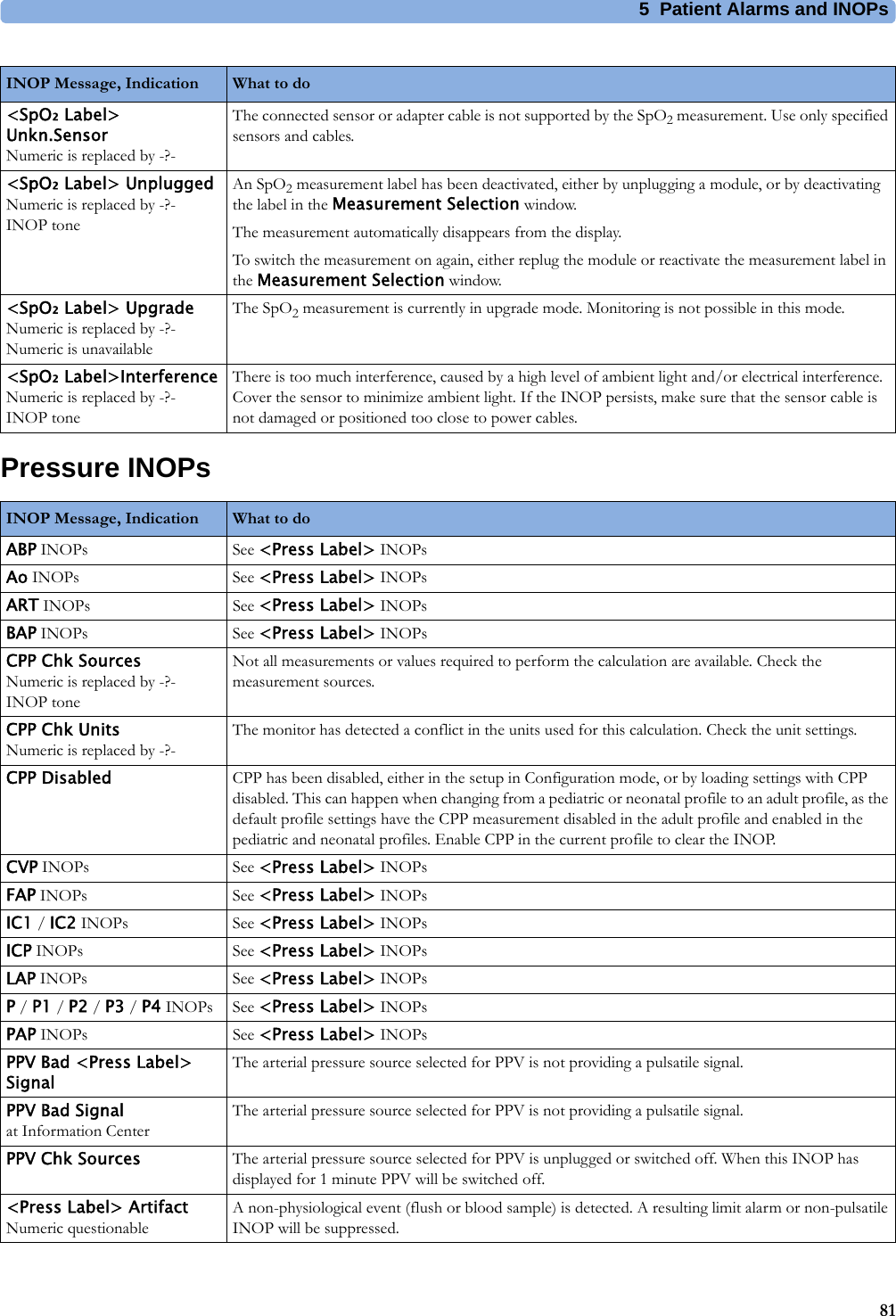
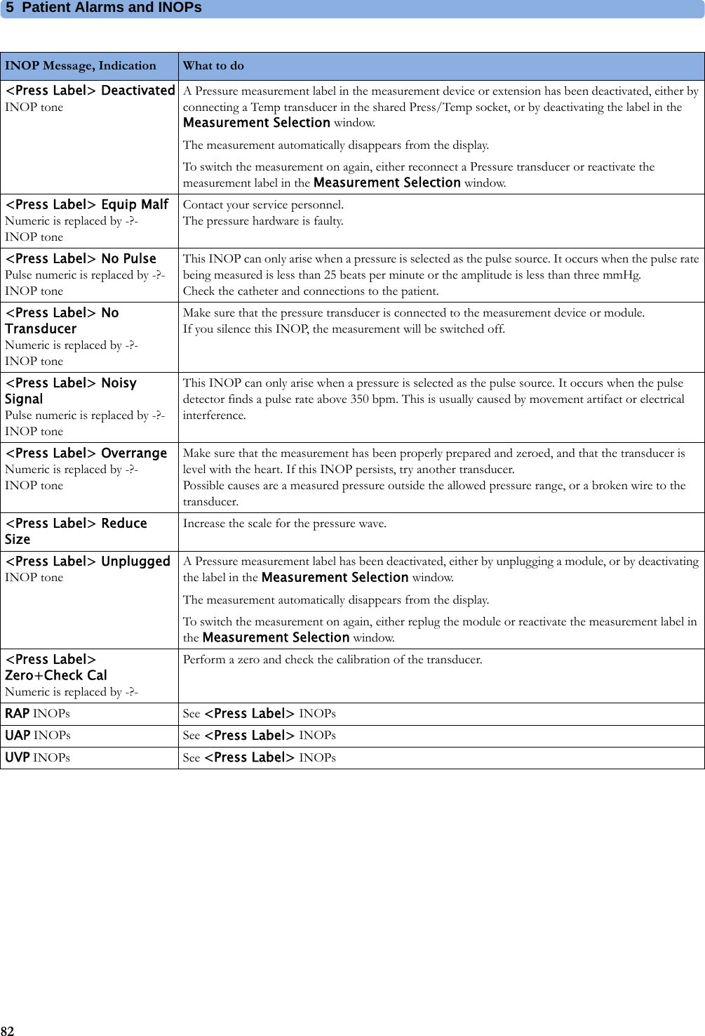
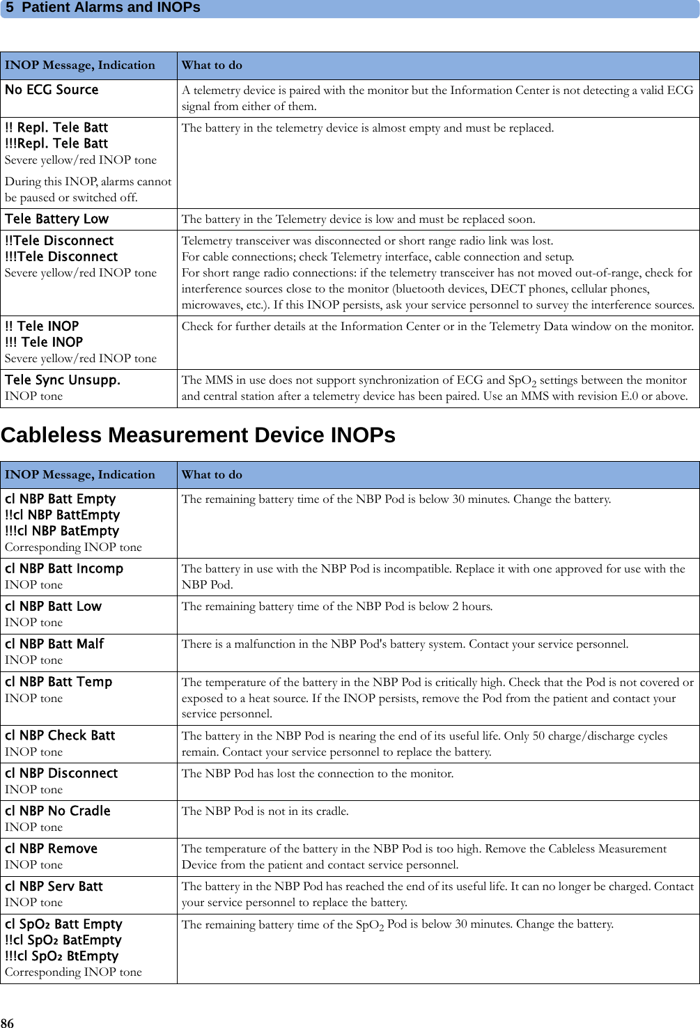
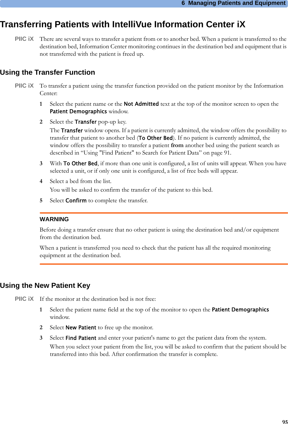
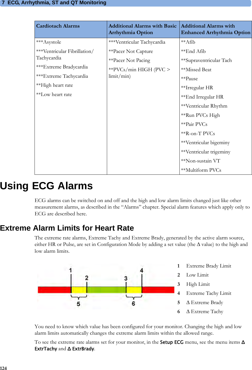
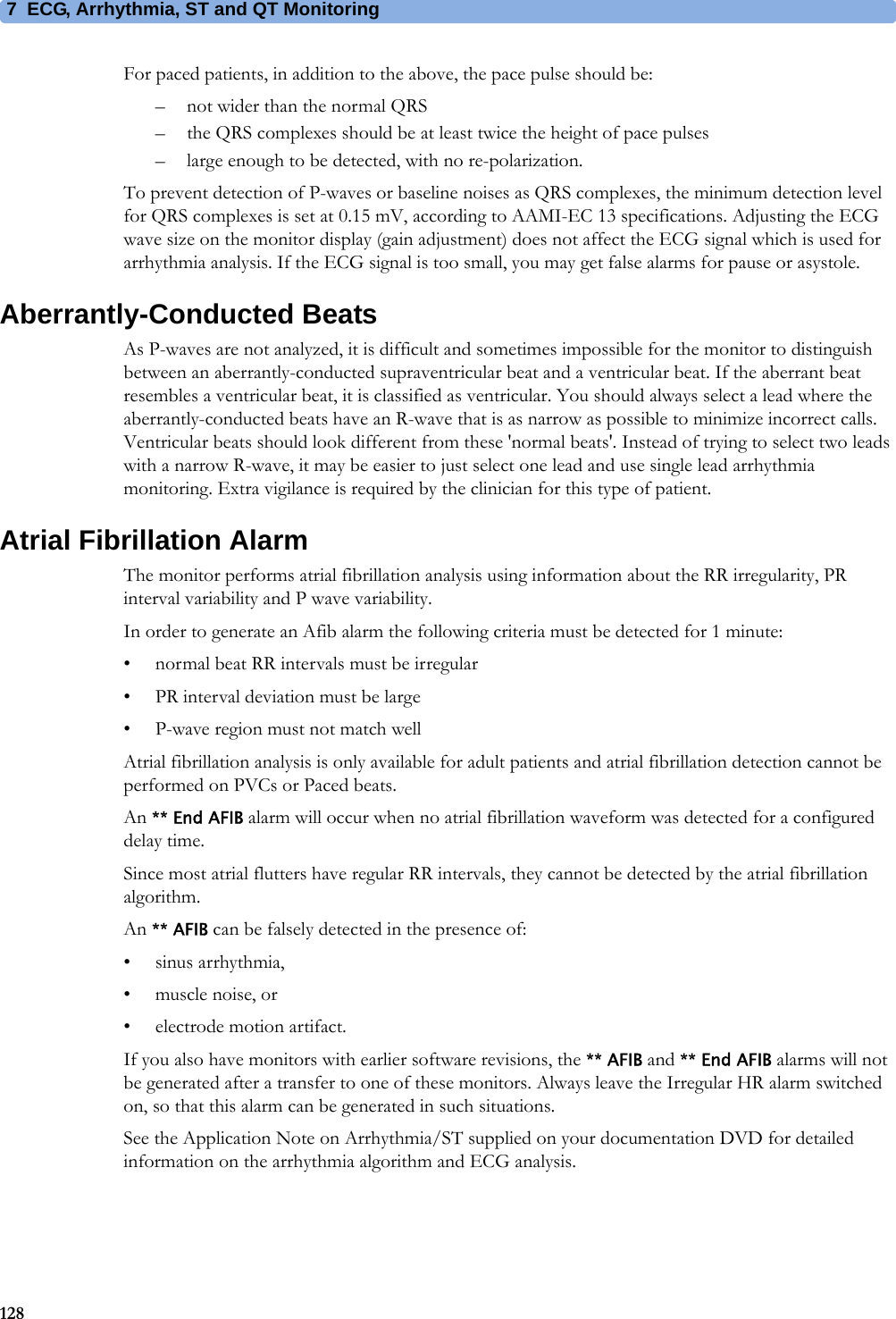
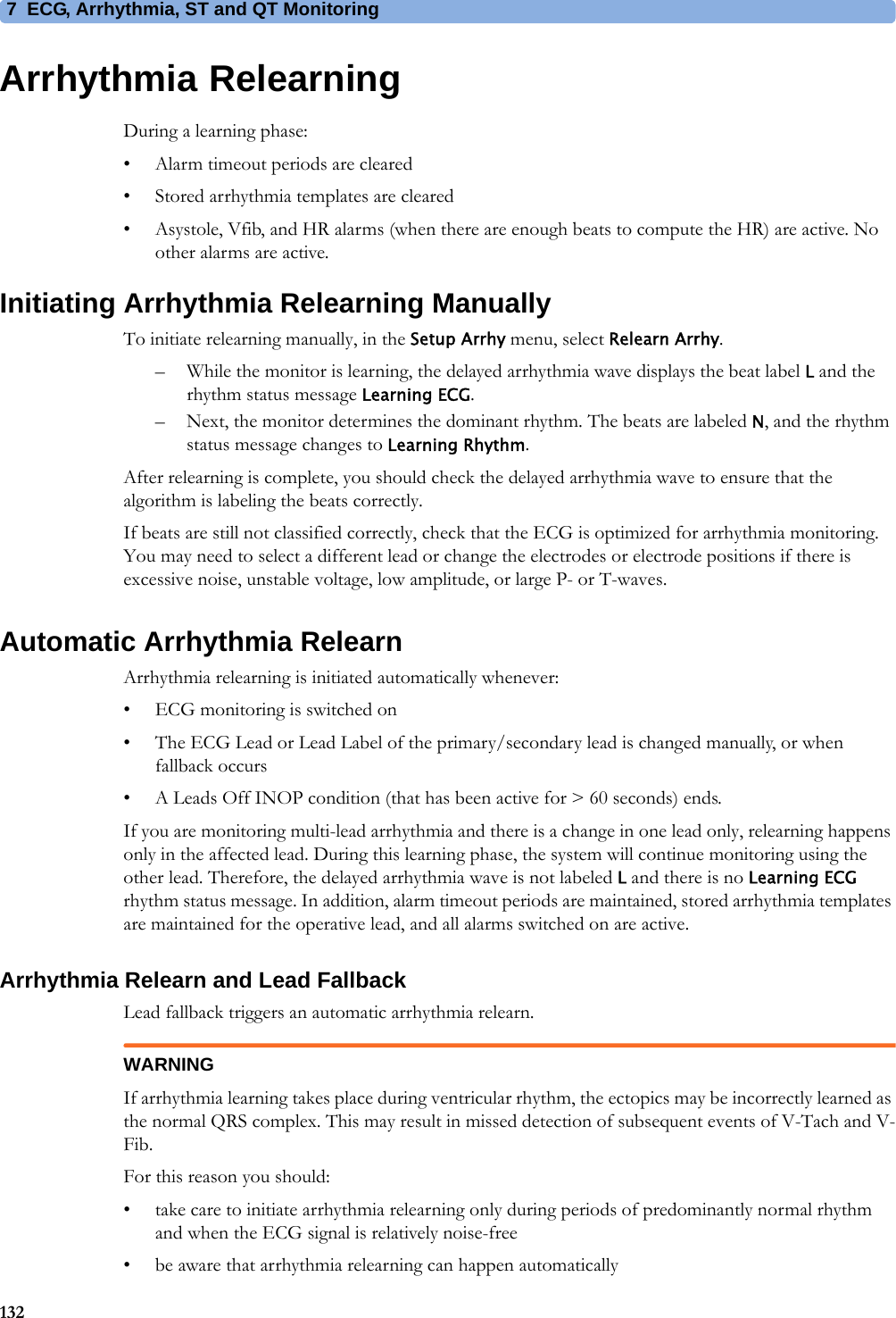
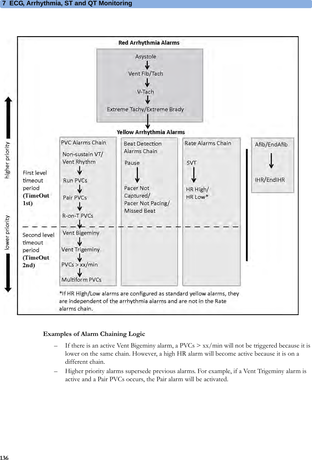
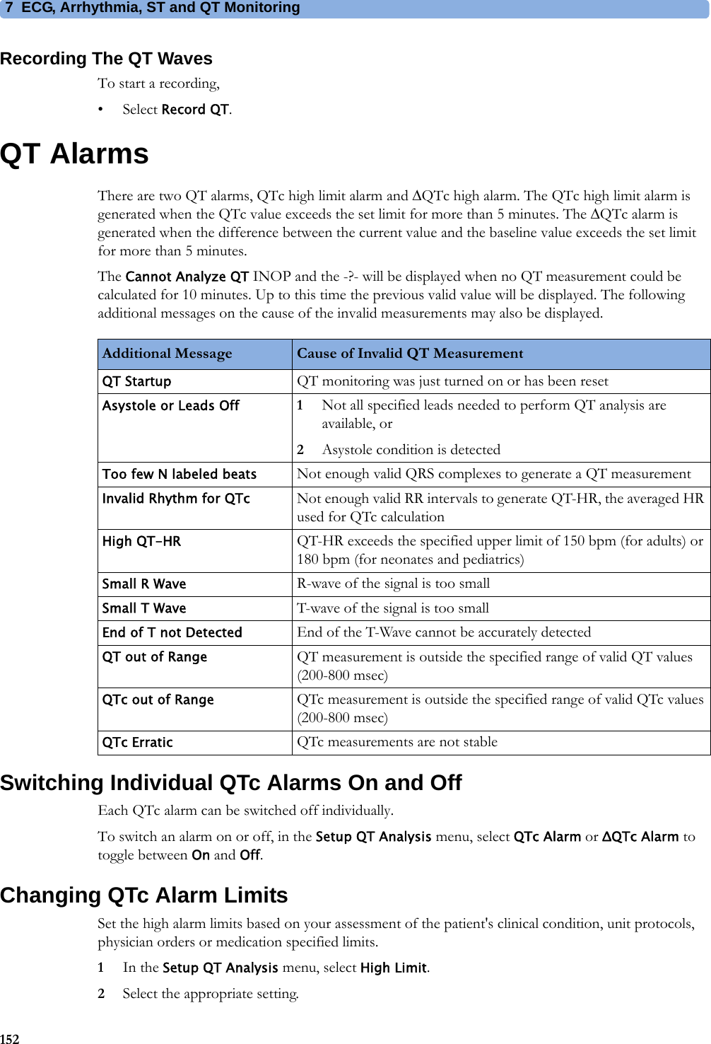
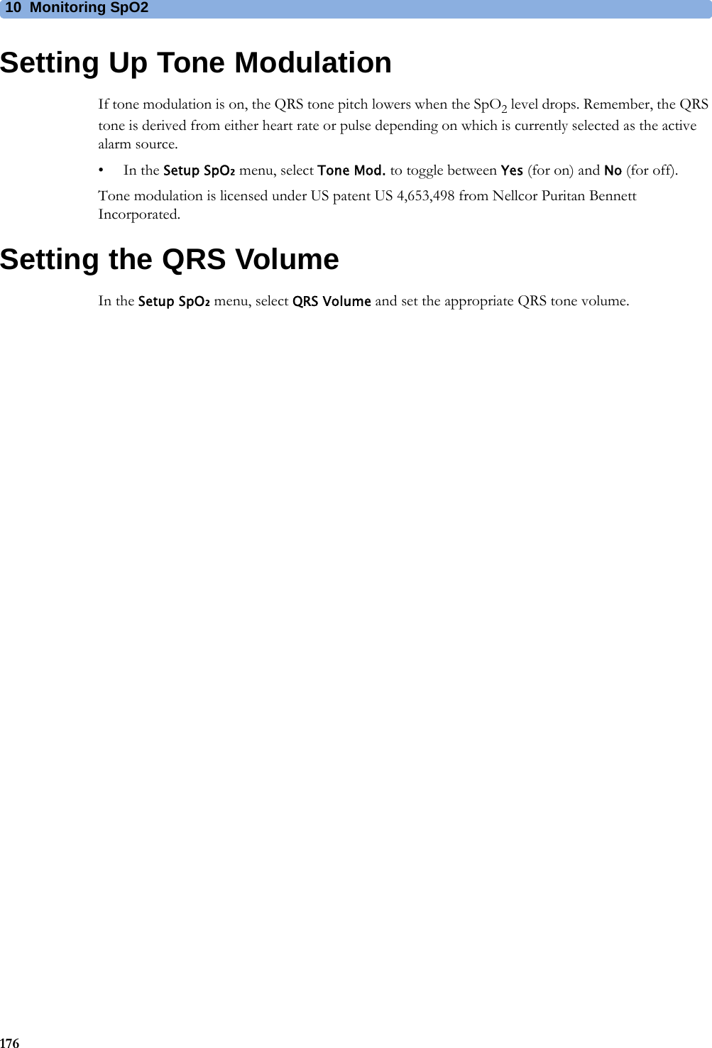
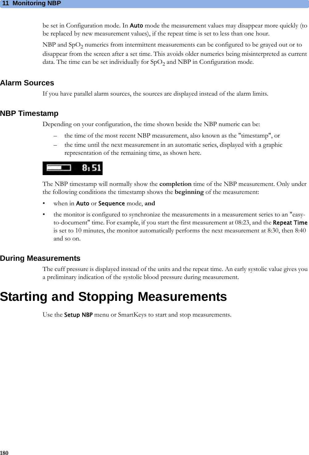
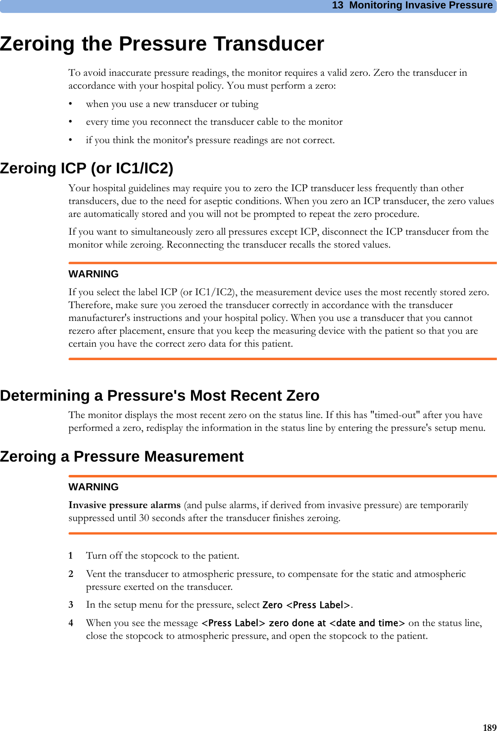
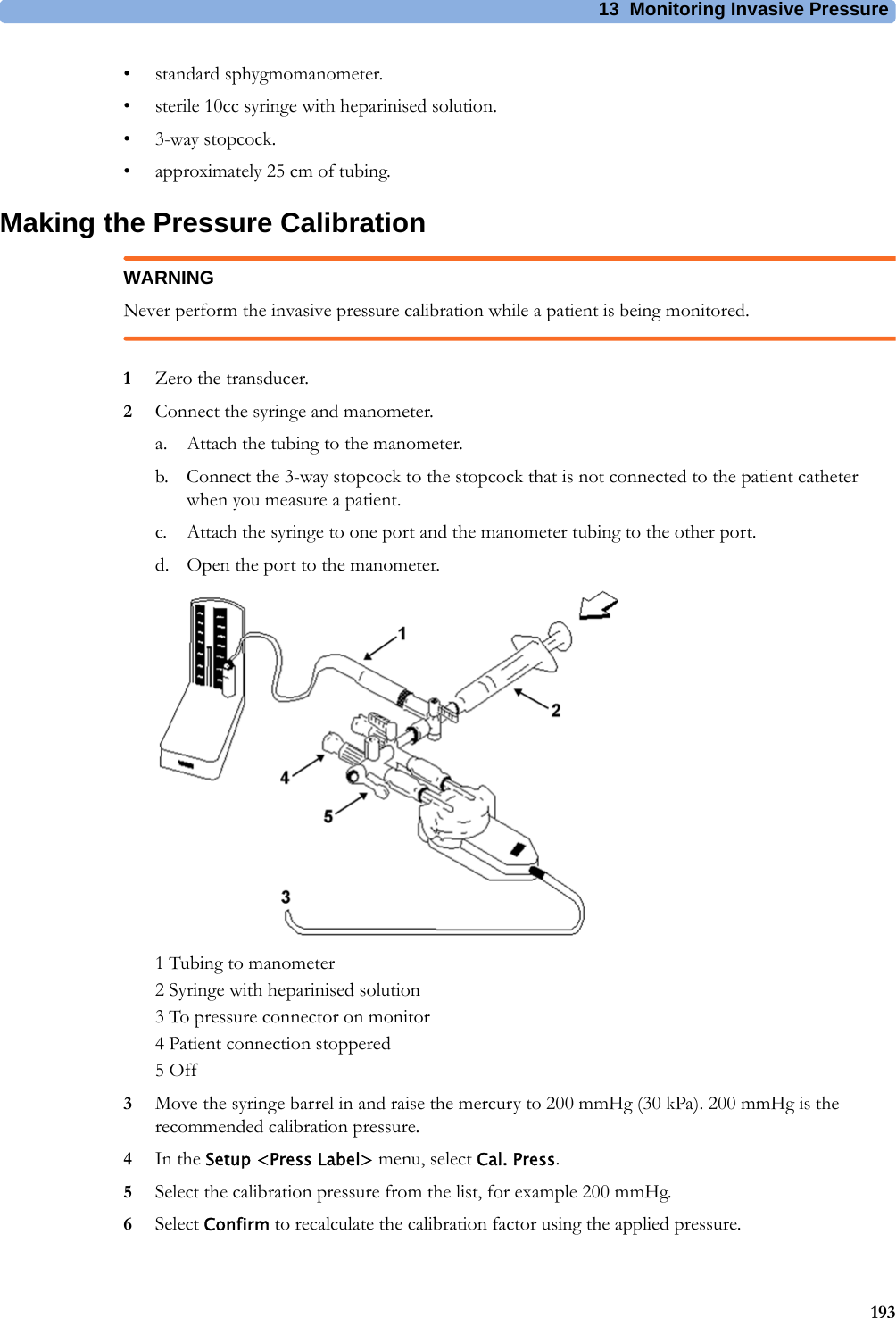
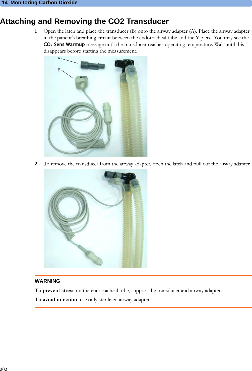
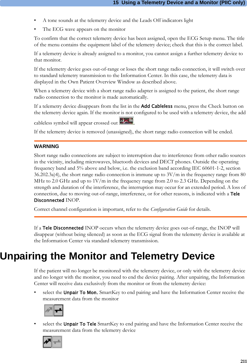
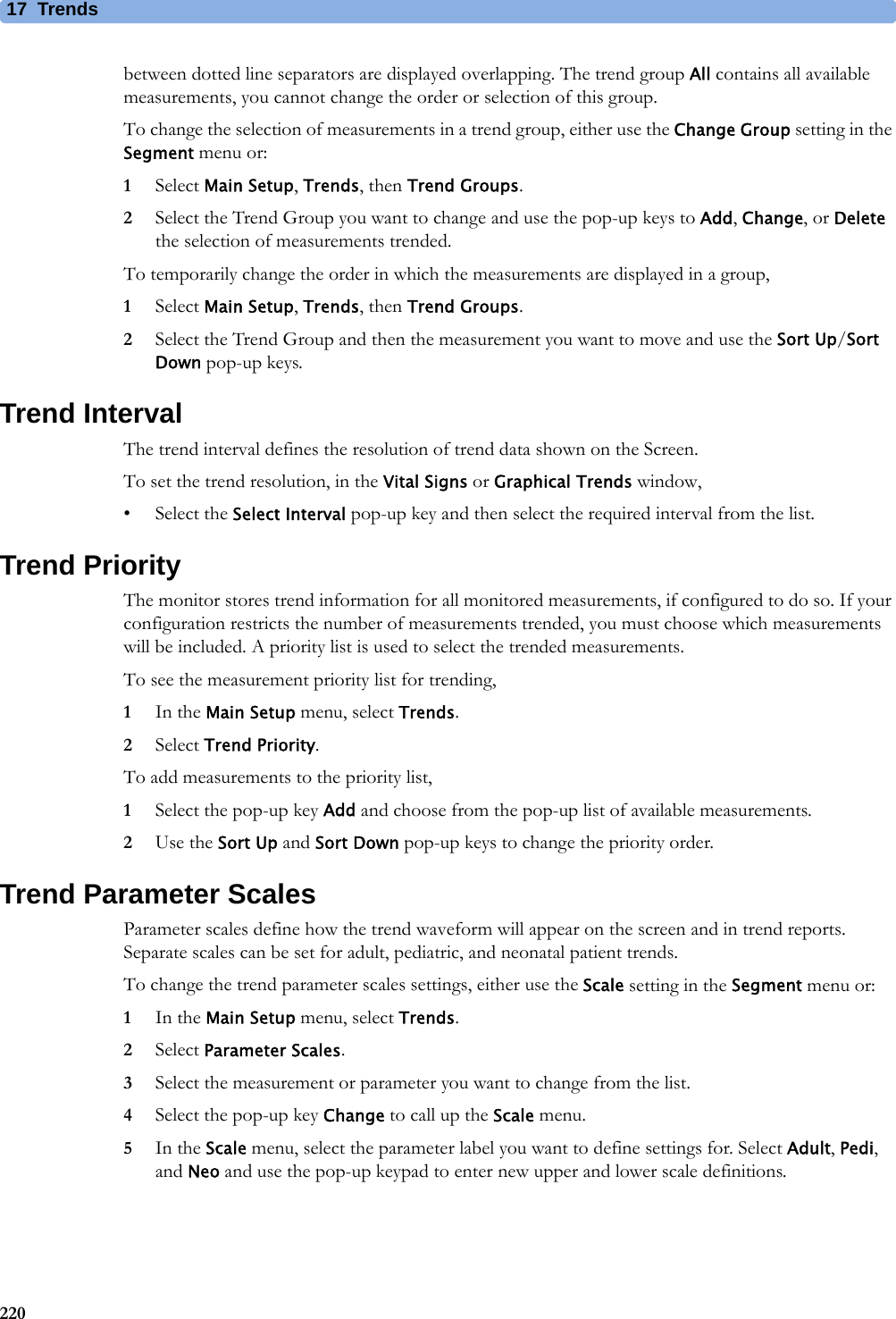
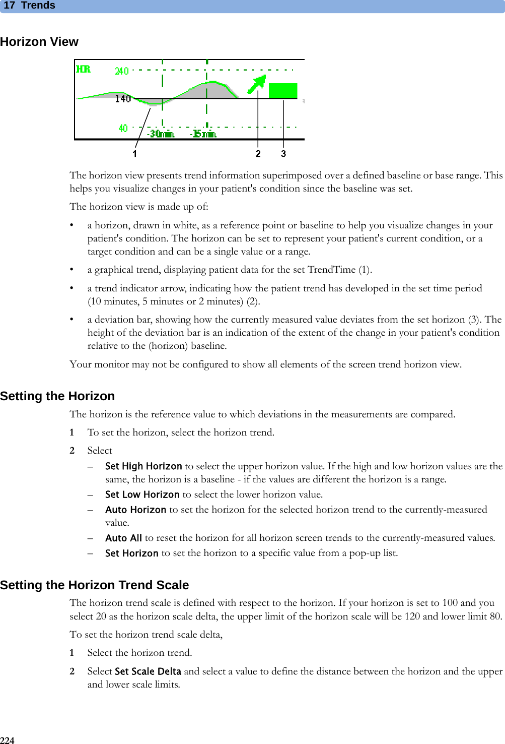
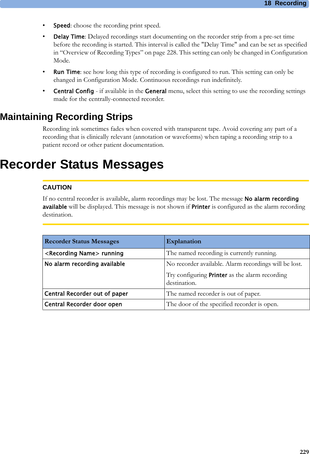
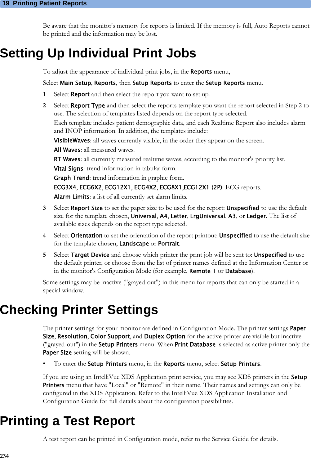
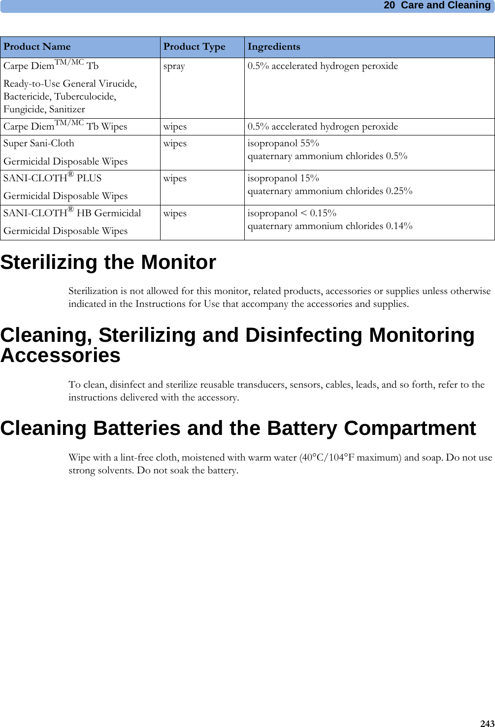
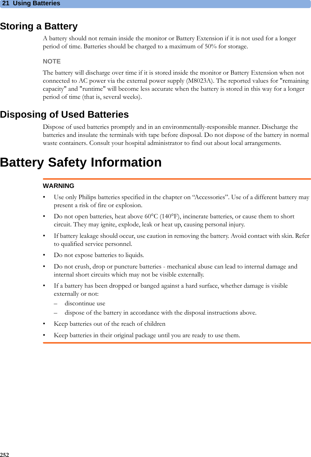
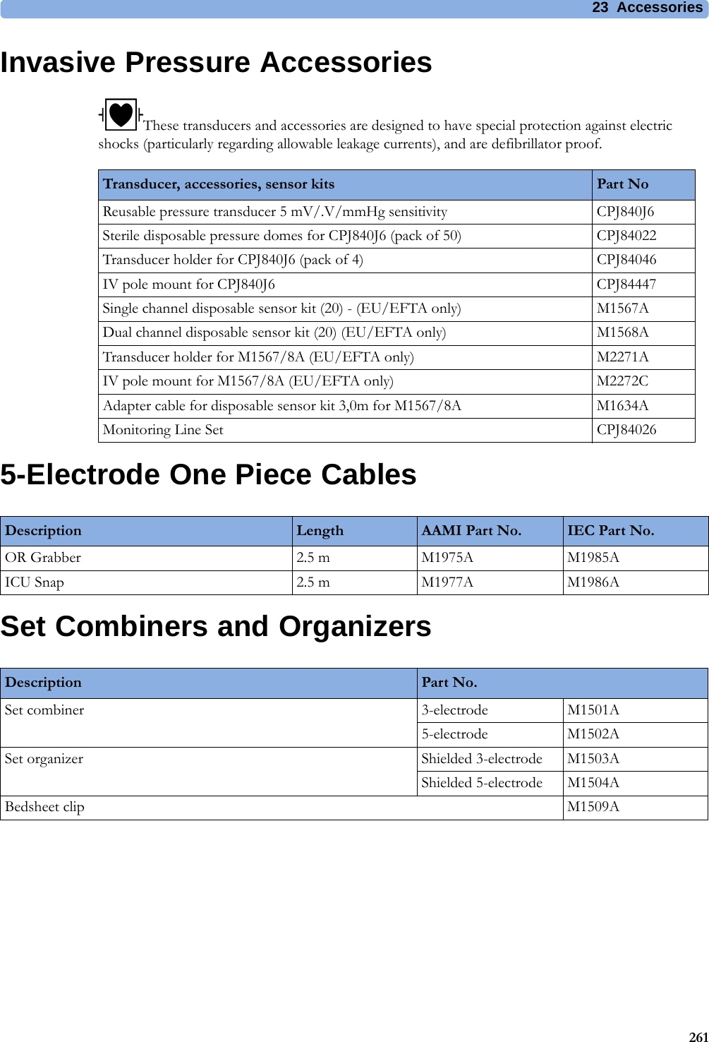
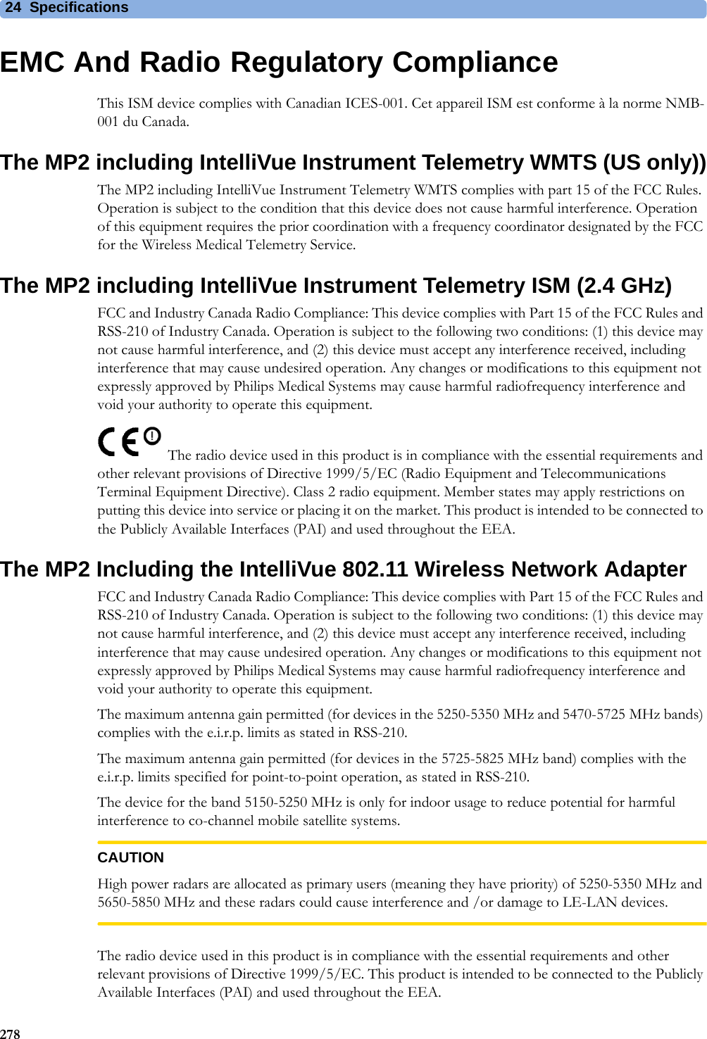
![5 Patient Alarms and INOPs77<ECG Lead> Lead Off!! <ECG Lead> Lead Off!!! <ECG Lead> Lead OffNumeric is replaced by -?-INOP toneNot all the required leads for ECG monitoring are connected. Check the ECG connections and make sure that the electrode indicated by <ECG lead> [RA, LA, LL, RL, V or C] electrodes is attached. In EASI mode, all 5 electrodes must be connected.ECG Leads Off!! ECG Leads Off!!!ECG Leads OffNumeric is replaced by -?-INOP toneCheck that all of the required ECG leads are attached, and that none of the electrodes have been displaced. The INOP may also be caused by a saturated or overloaded ECG amplifier.ECG Noisy Elec <ECG Lead>The ECG signal from the named ECG electrodes [RA, LA, LL, RL, V (or C)] is noisy. Check the ECG connections and make sure that the electrode indicated is attached.ECG Noisy SignalINOP toneThe ECG signal is too noisy. Check that the electrodes are properly placed and have not dried out. Remove any possible sources of signal noise (such as power cords) from the area around the cable and the patient.The ECG signal may be saturated or overloaded.!!ECG/AR AlarmsOff All ECG alarms have been switched off, or the HR alarm source is not ECG. To resume ECG alarm generation, switch ECG alarms on or select ECG as the alarm source.ECG/Arrh AlarmsOff!!ECG/AR AlarmsOffAll ECG alarms have been switched off, or the HR alarm source is not ECG. To resume ECG alarm generation, switch ECG alarms on or select ECG as the alarm source.EcgOut Equip MalfINOP toneThere is a problem with the device connected to the ECG Out connector. Contact your service personnel.LA Lead OffNumeric is replaced by -?- for 10 seconds.INOP toneThe LA electrode has become detached from the patient or the lead set has been changed. Reattach the electrode or select New Lead Setup in the Setup ECG menu to confirm the new lead set.LL Lead OffNumeric is replaced by -?- for 10 seconds.INOP toneThe LL electrode has become detached from the patient or the lead set has been changed. Reattach the electrode or select New Lead Setup in the Setup ECG menu to confirm the new lead set.RA Lead OffNumeric is replaced by -?-INOP toneThe RA electrode has become detached from the patient or the lead set has been changed. Reattach the electrode or select New Lead Setup in the Setup ECG menu to confirm the new lead set.RL Lead OffNumeric is replaced by -?- for 10 seconds.INOP toneThe RL electrode has become detached from the patient or the lead set has been changed. Reattach the electrode or select New Lead Setup in the Setup ECG menu to confirm the new lead set.Some ECG AlarmsOff This message appears (if configured to do so) when the on/off settings of the yellow arrhythmia alarms differ from the current Profile.V Lead OffNumeric is replaced by -?- for 10 seconds.INOP toneThe V electrode (IEC: C electrode) has become detached from the patient or the lead set has been changed. Reattach the electrode or select New Lead Setup in the Setup ECG menu to confirm the new lead set.INOP Message, Indication What to do](https://usermanual.wiki/Philips-Medical-Systems-North-America/WLANBV2.User-Manual-IntelliVue-MP2/User-Guide-2137734-Page-77.png)
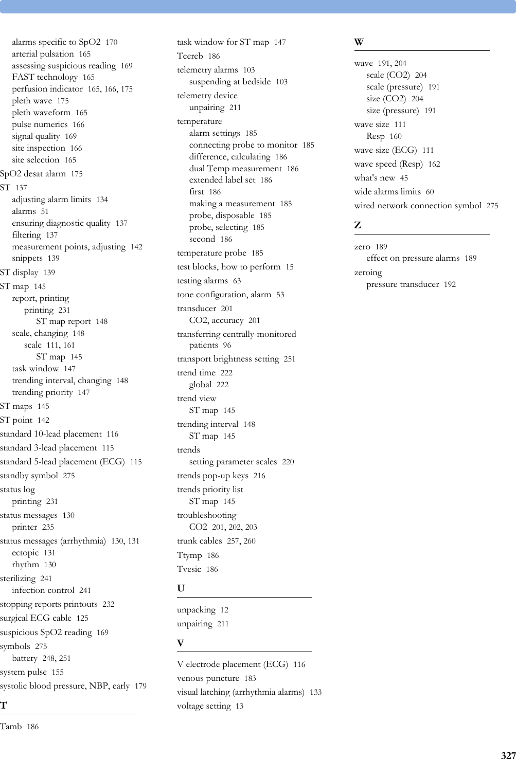
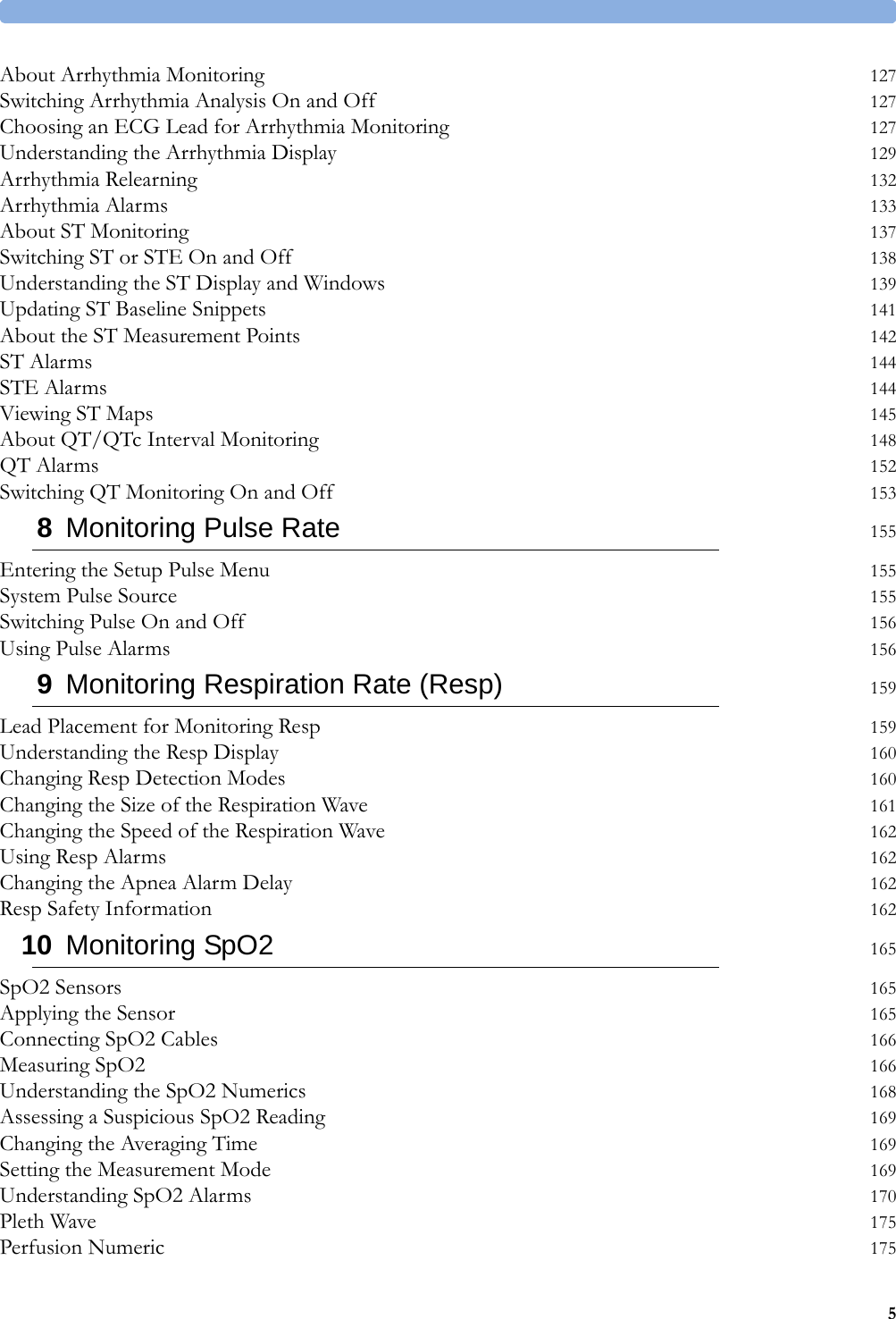
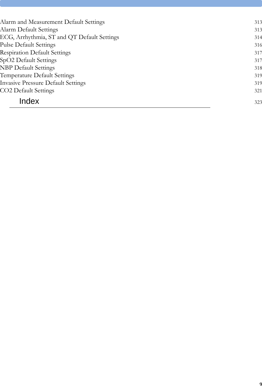
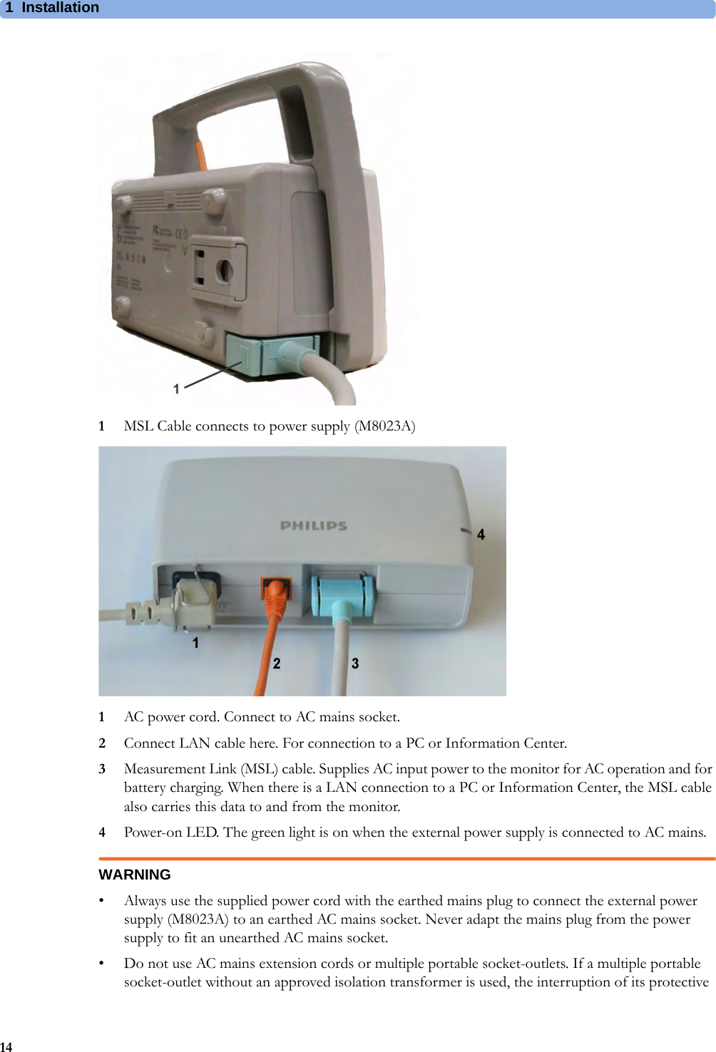
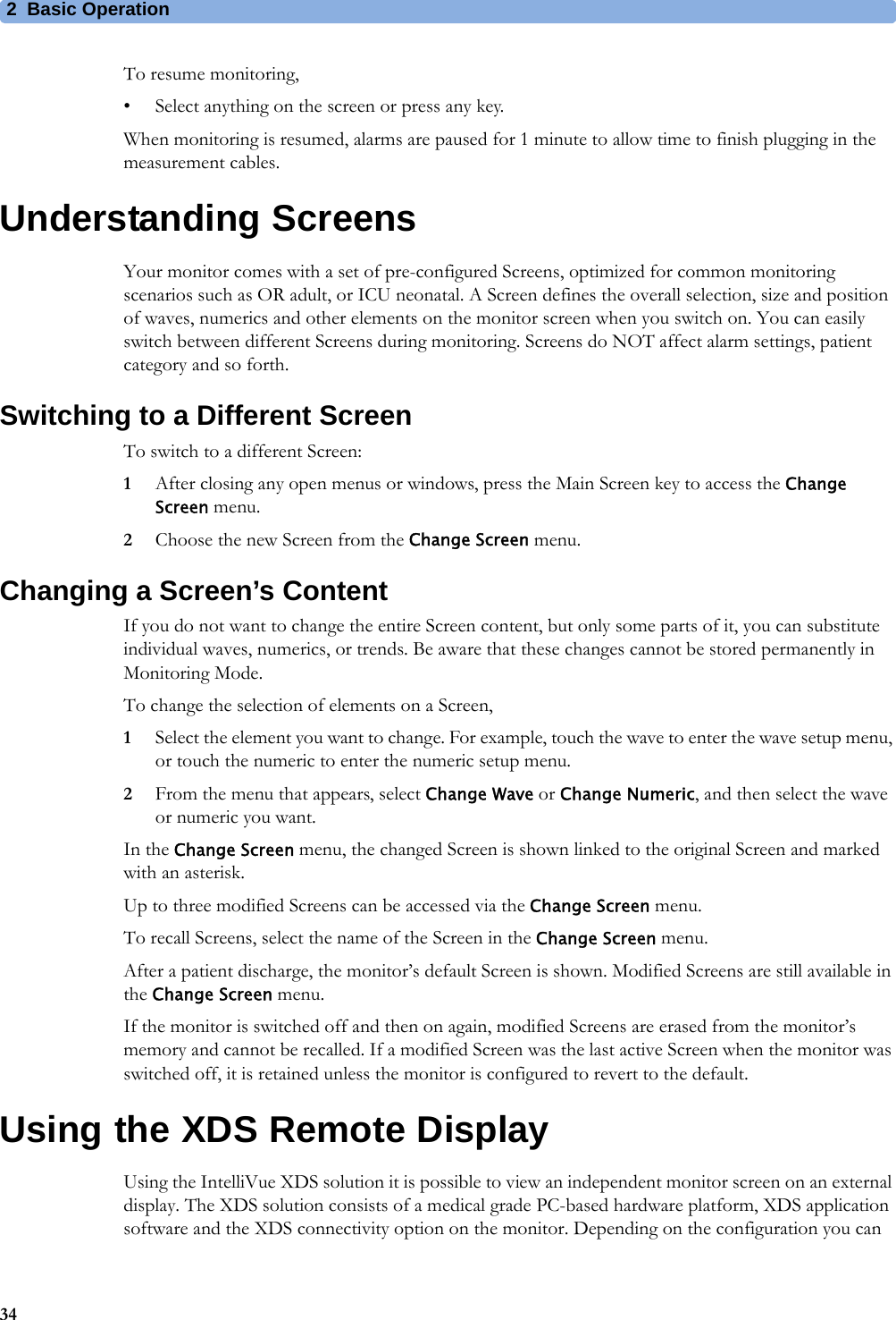
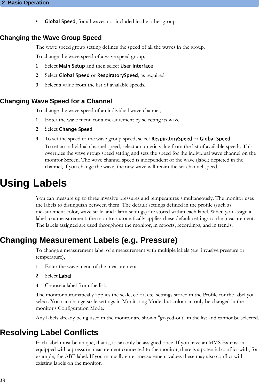
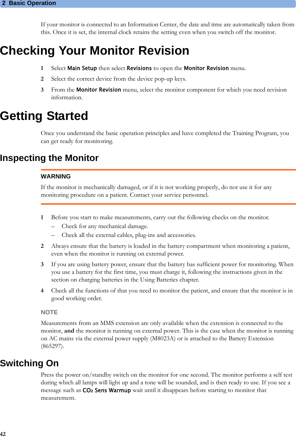
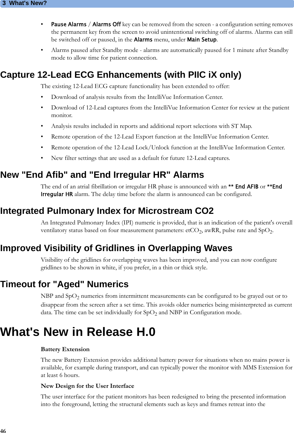
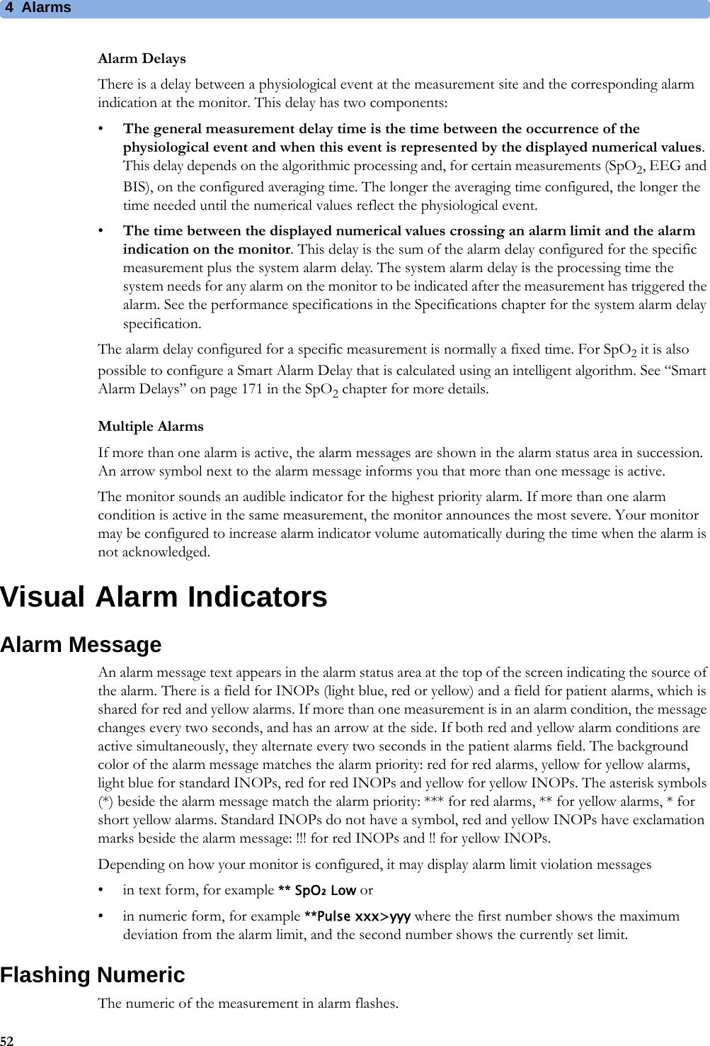
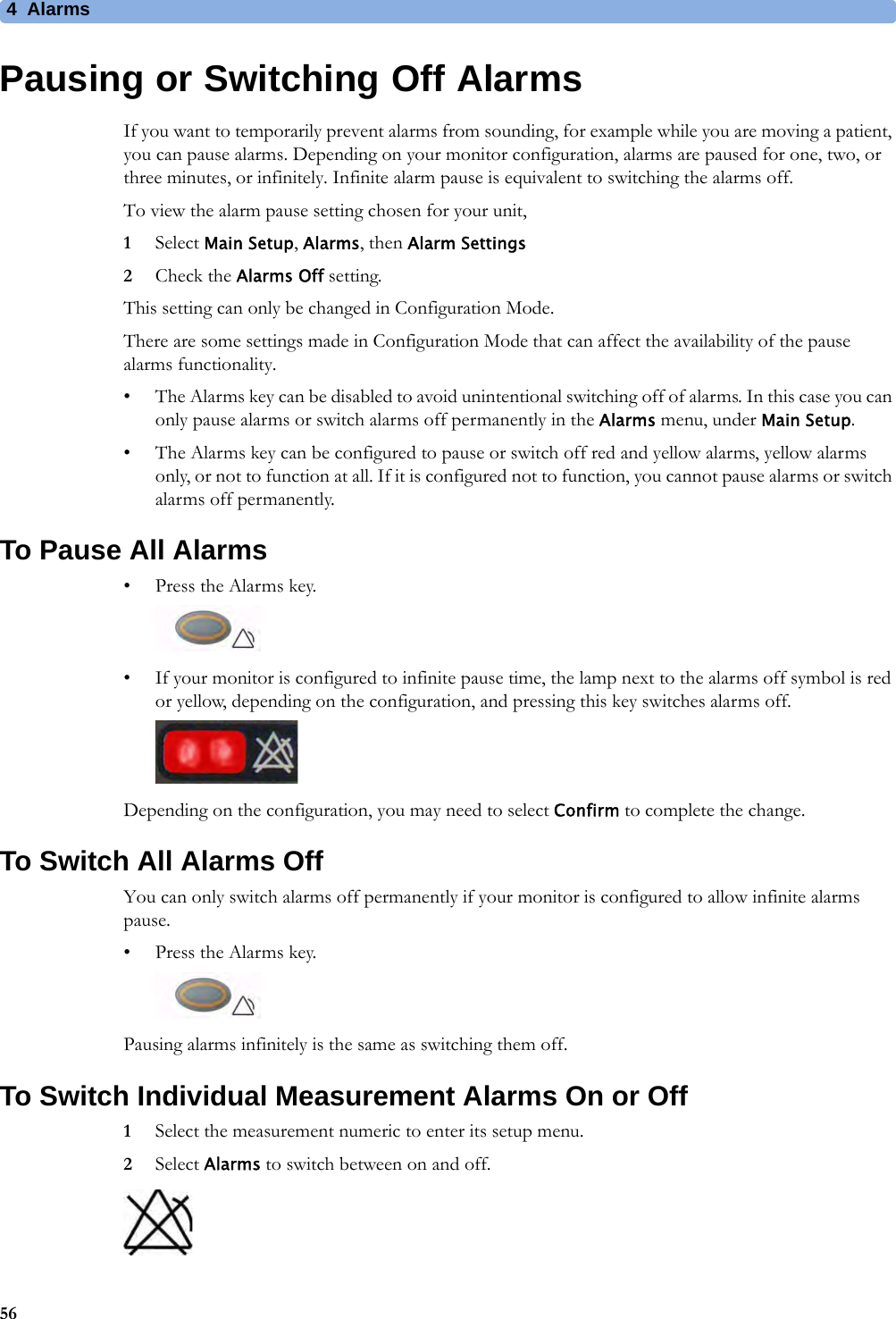
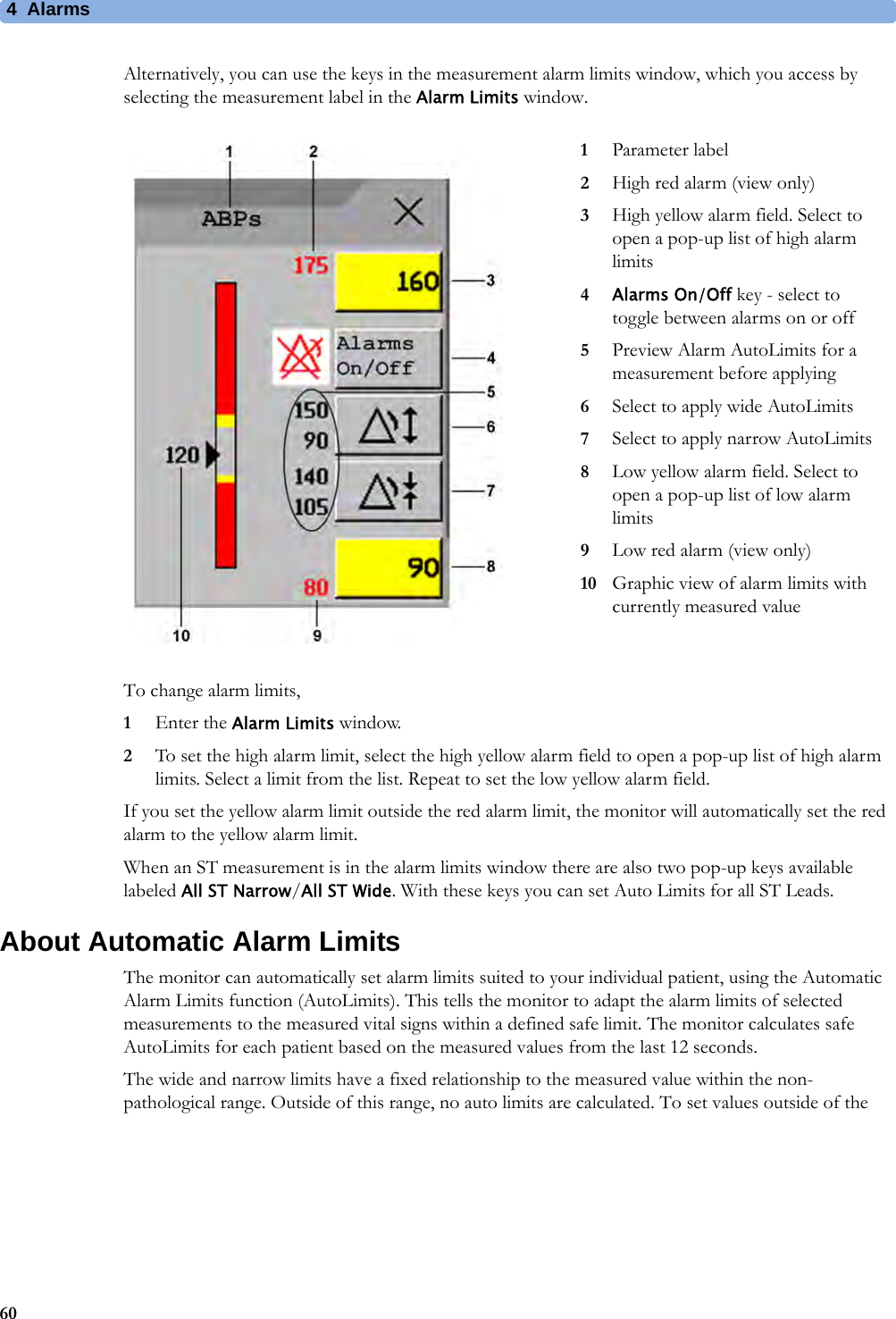
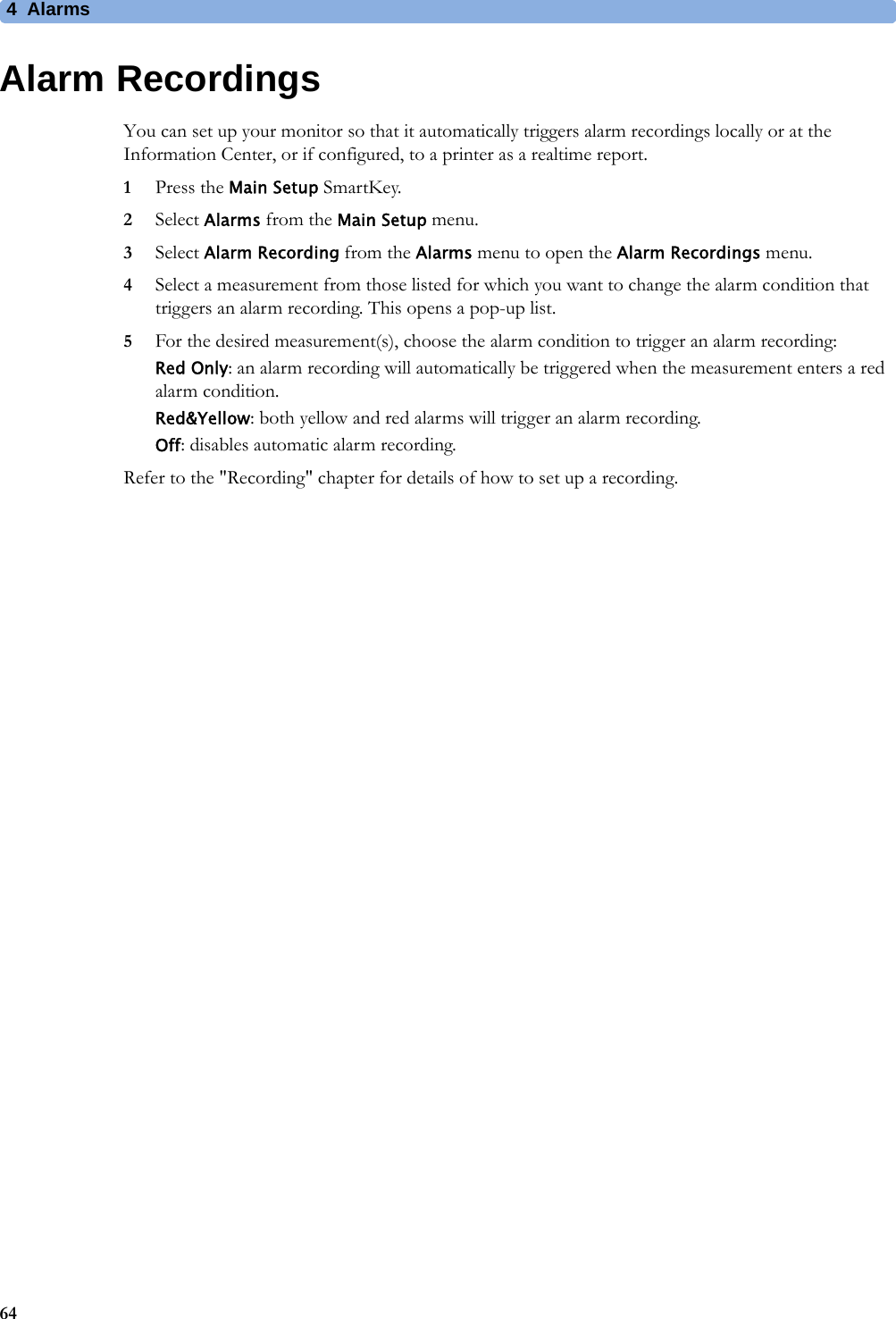
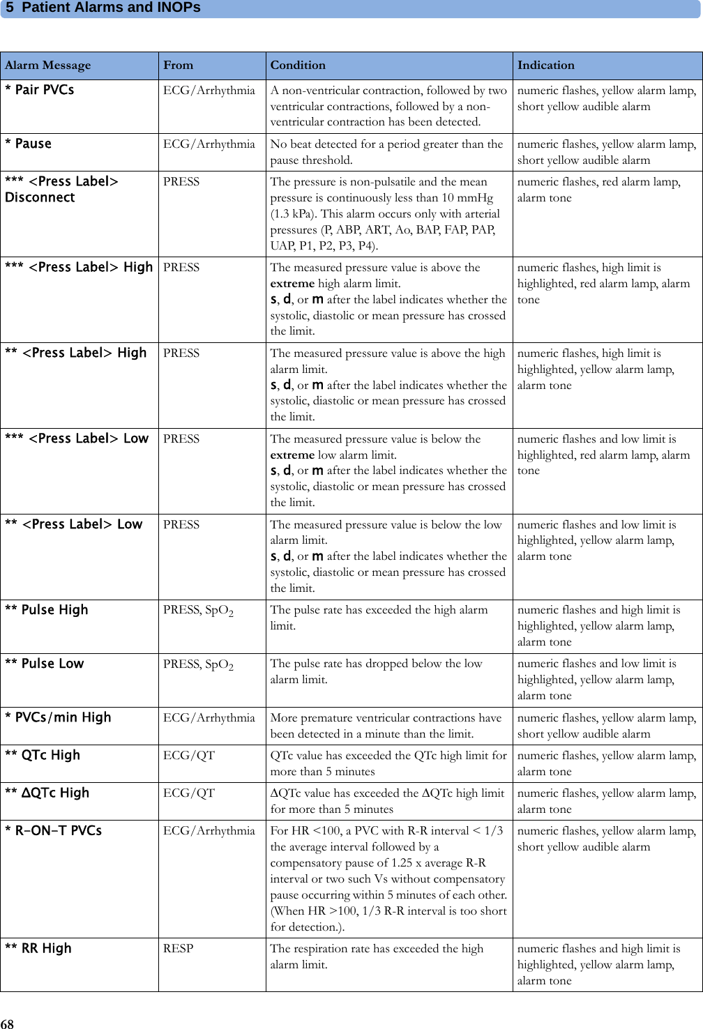
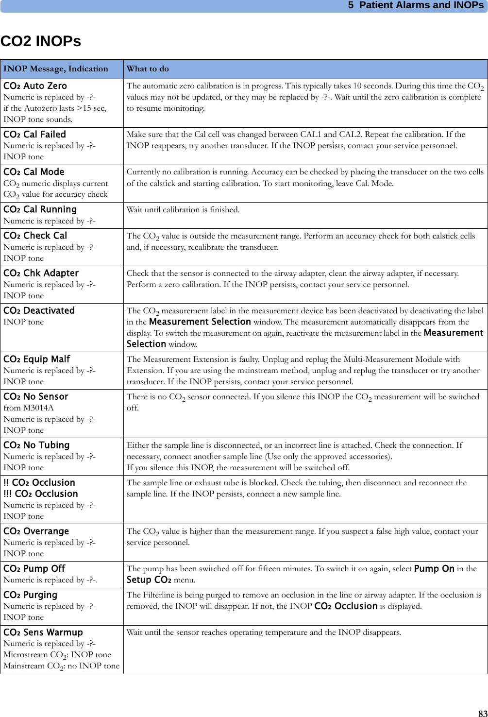
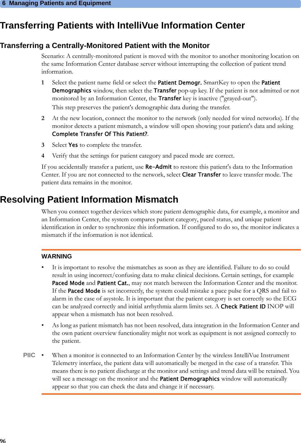
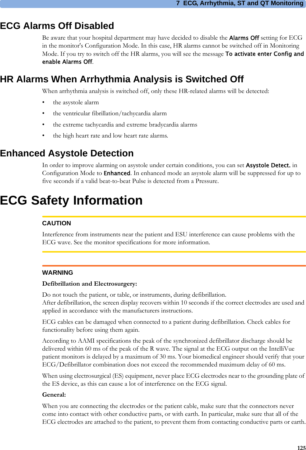
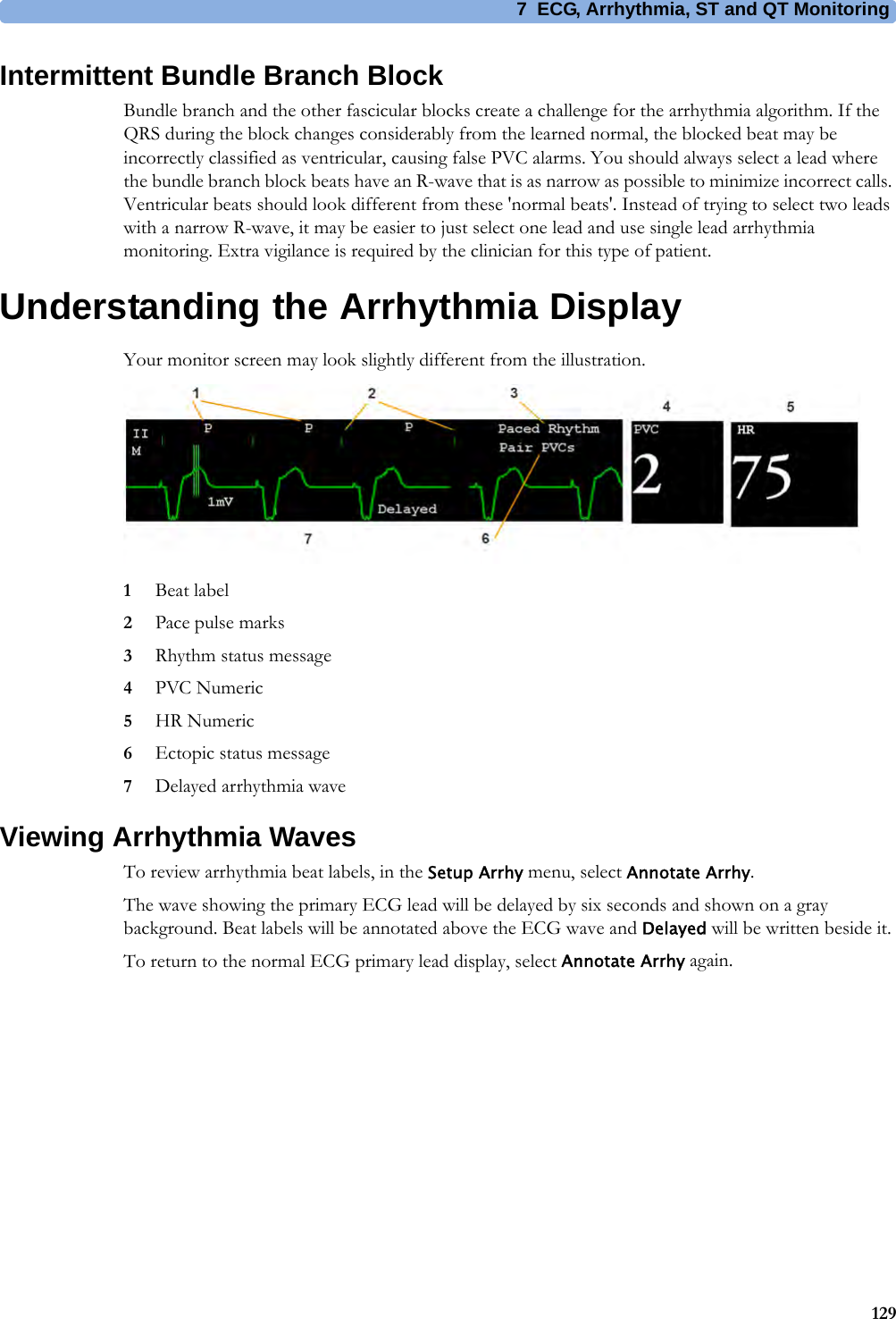
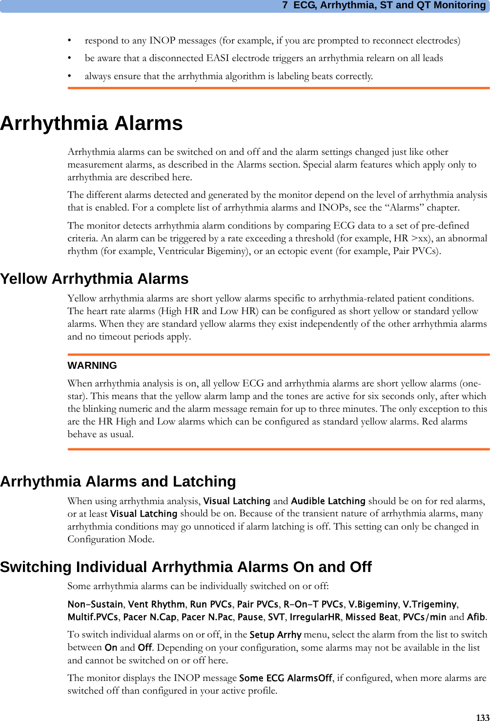
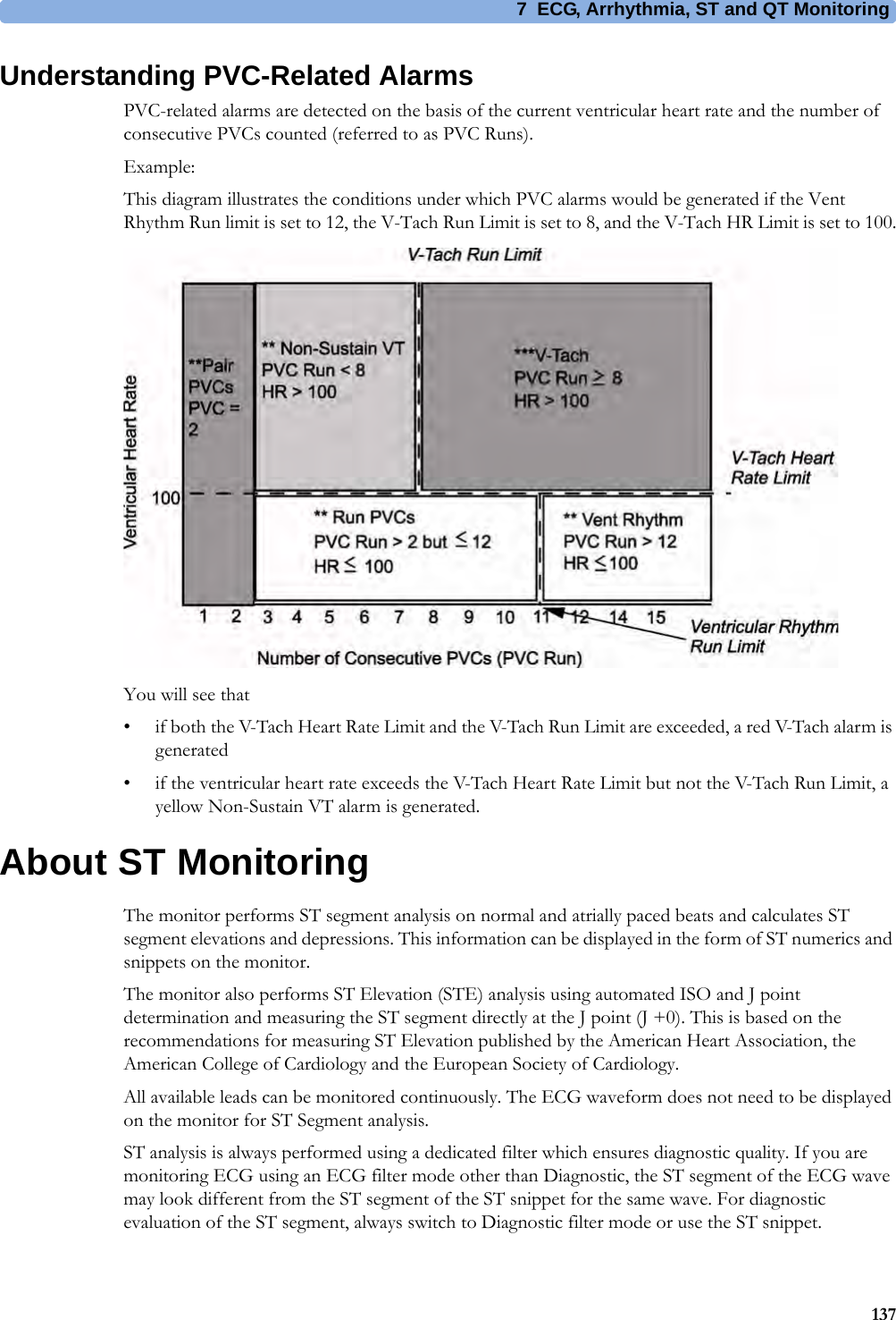
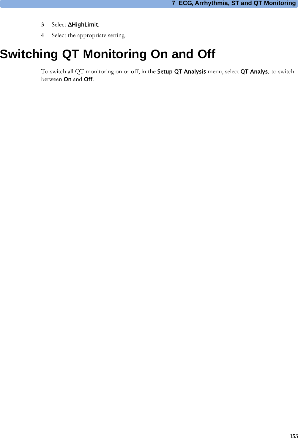
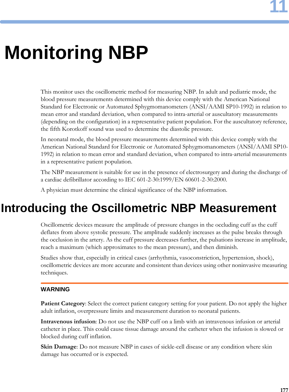
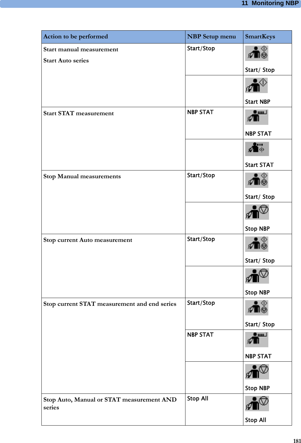
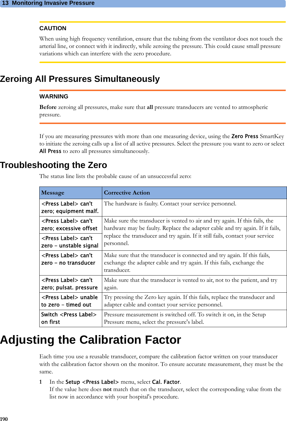
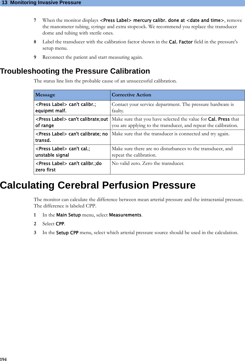
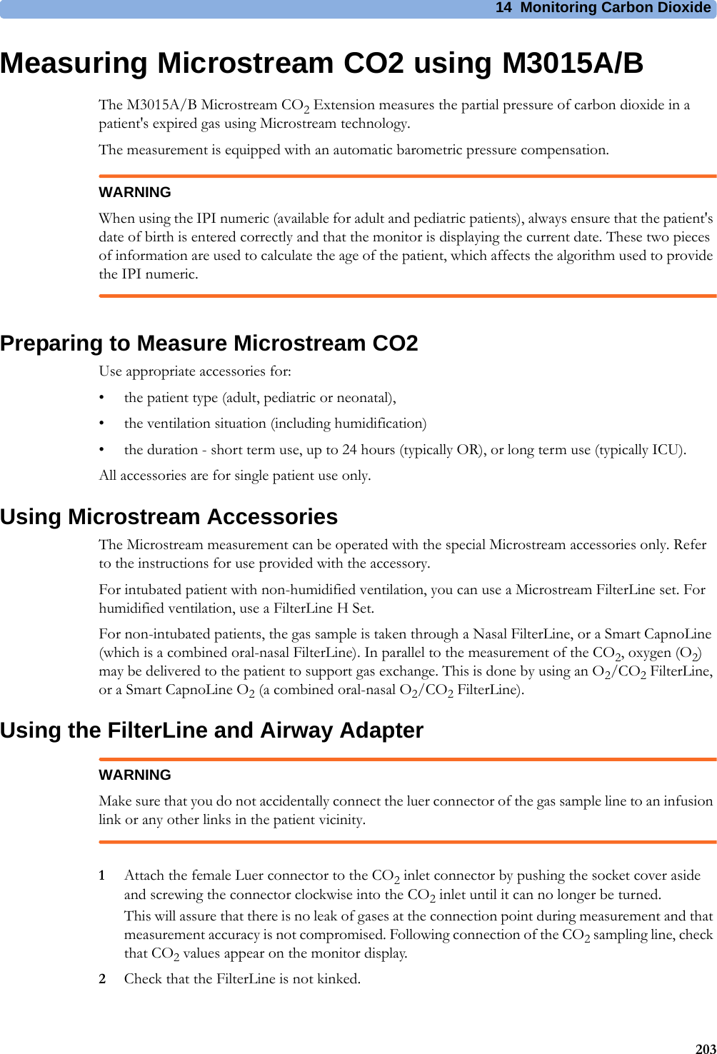
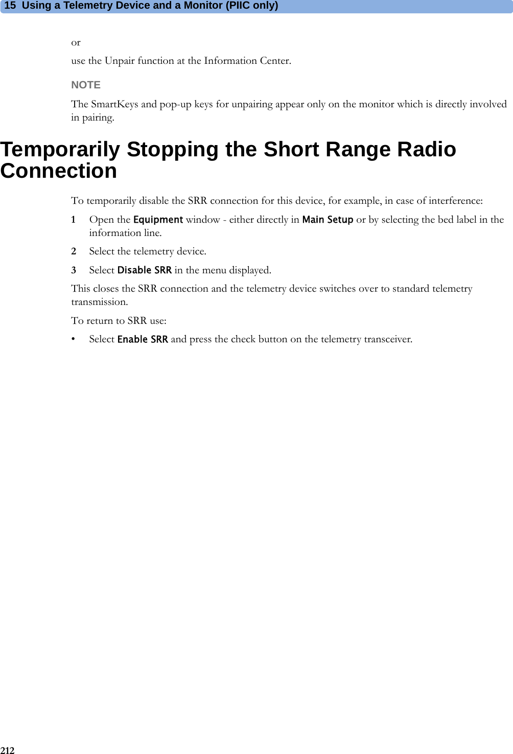
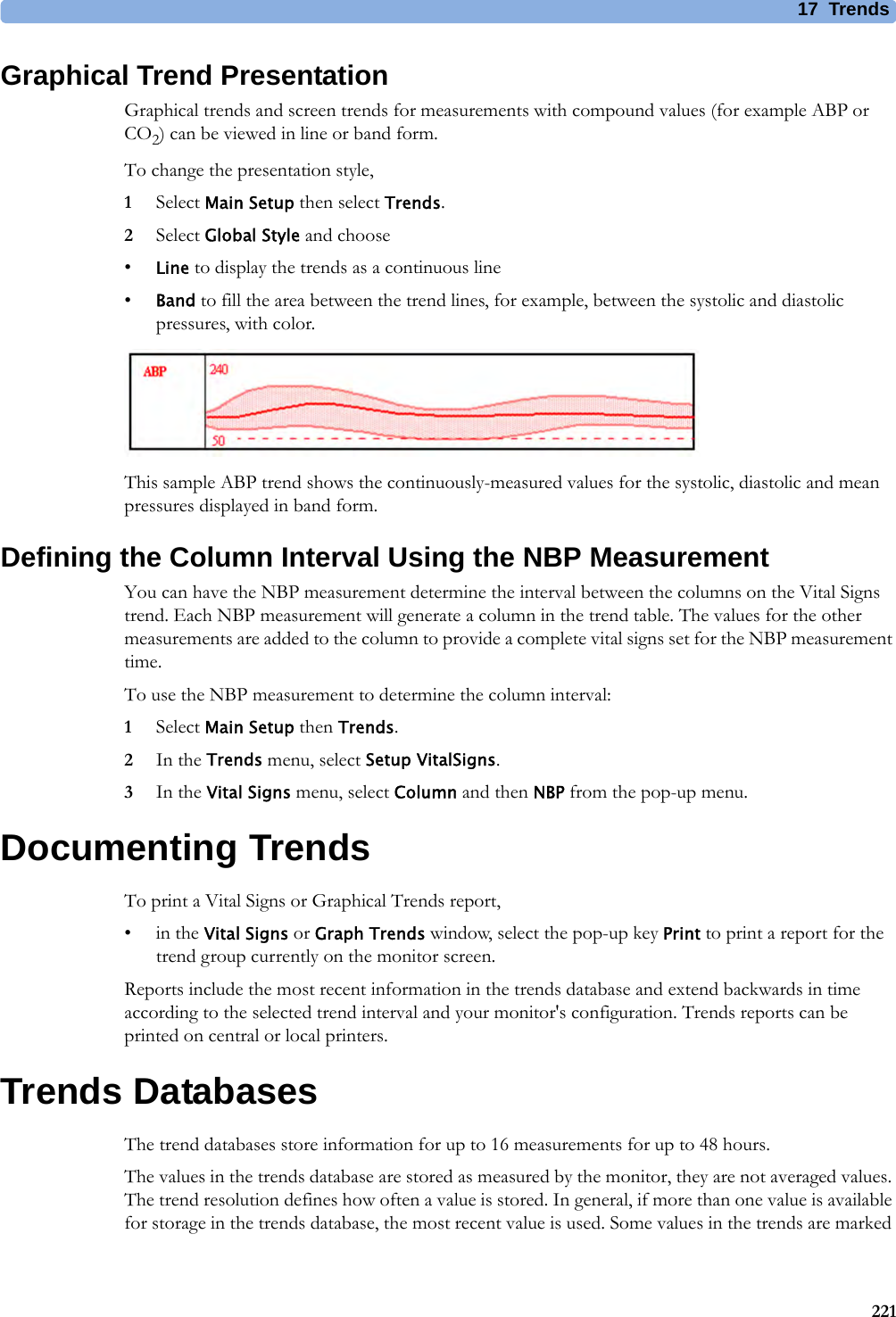
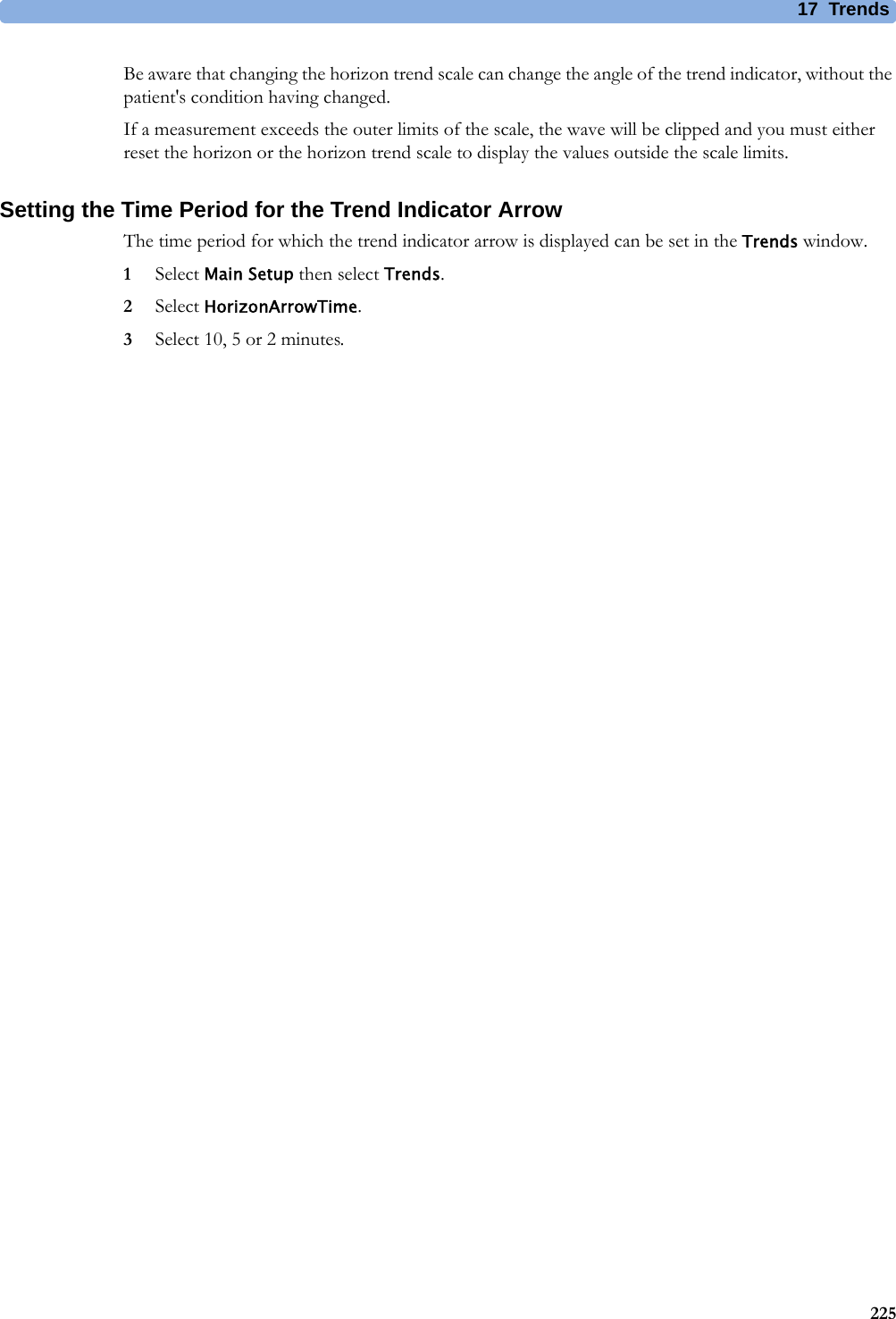
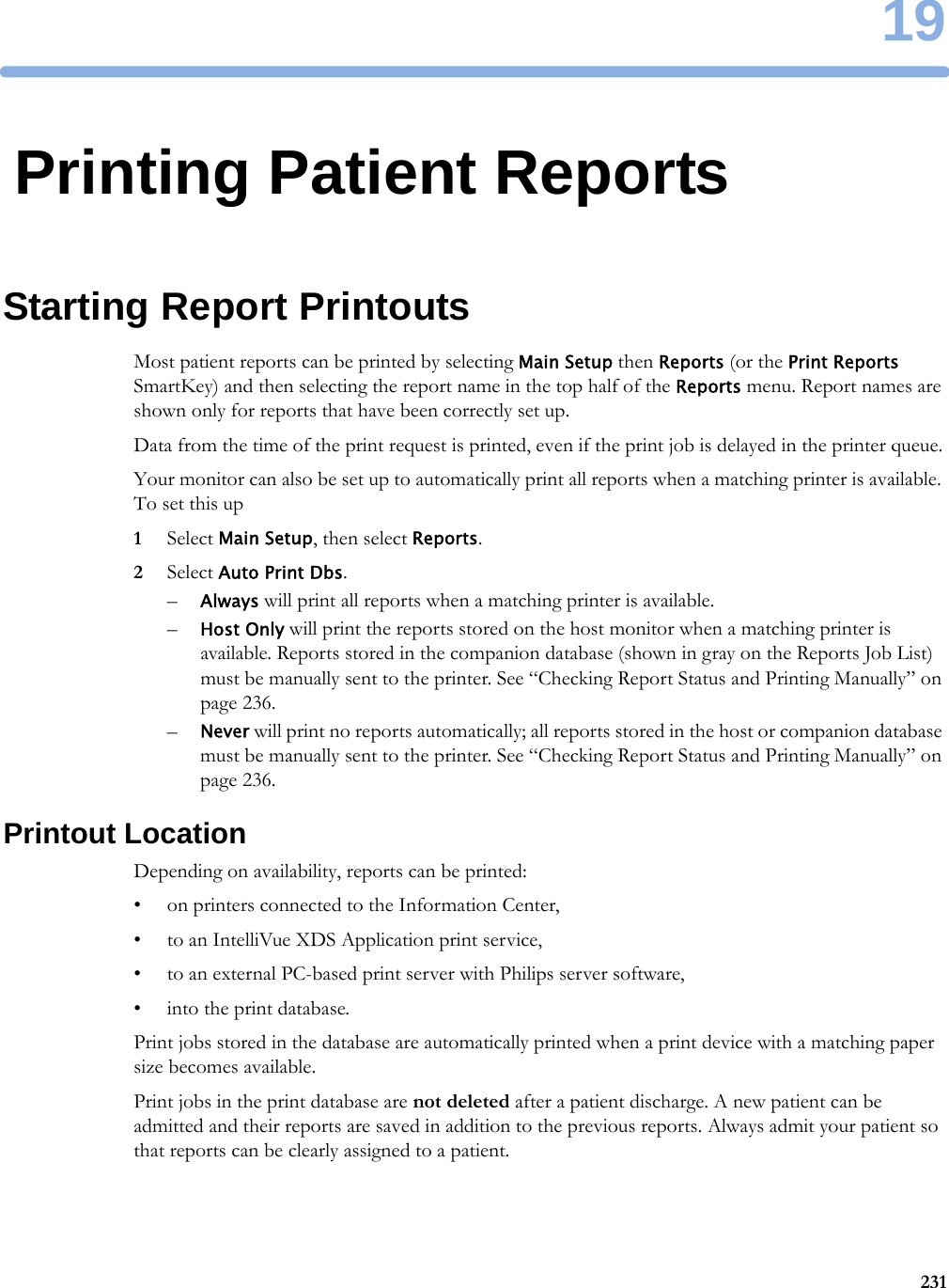
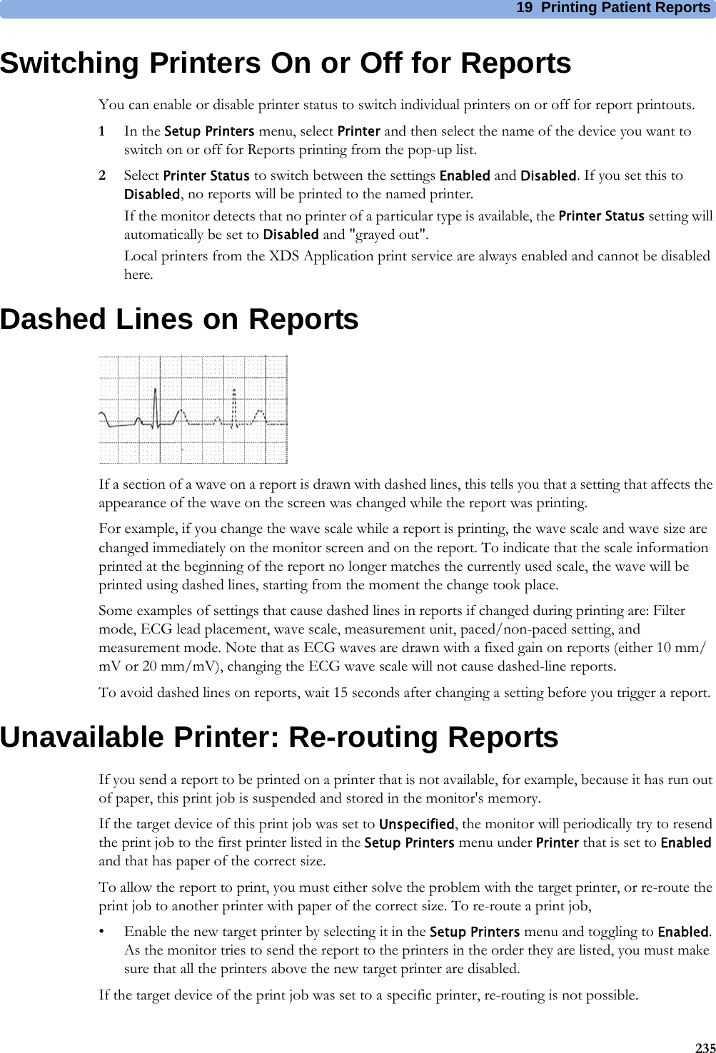
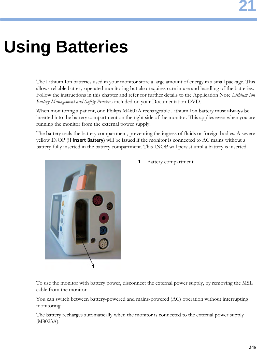
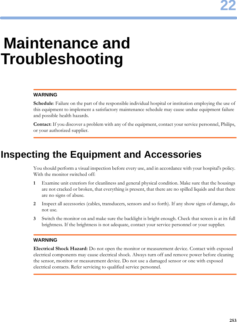
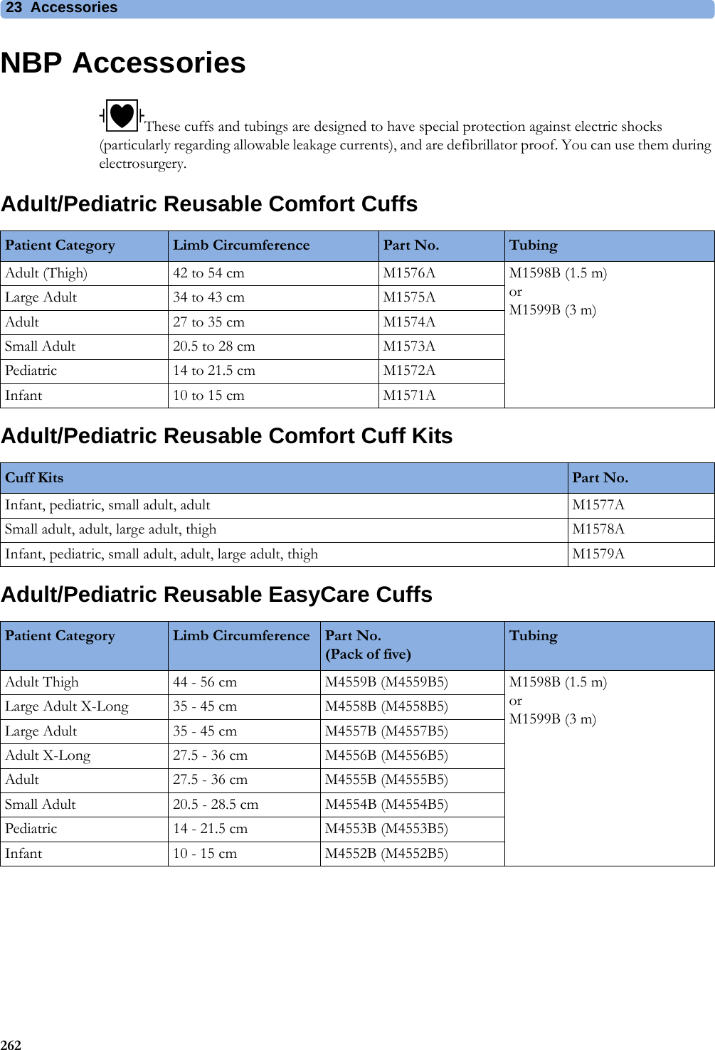
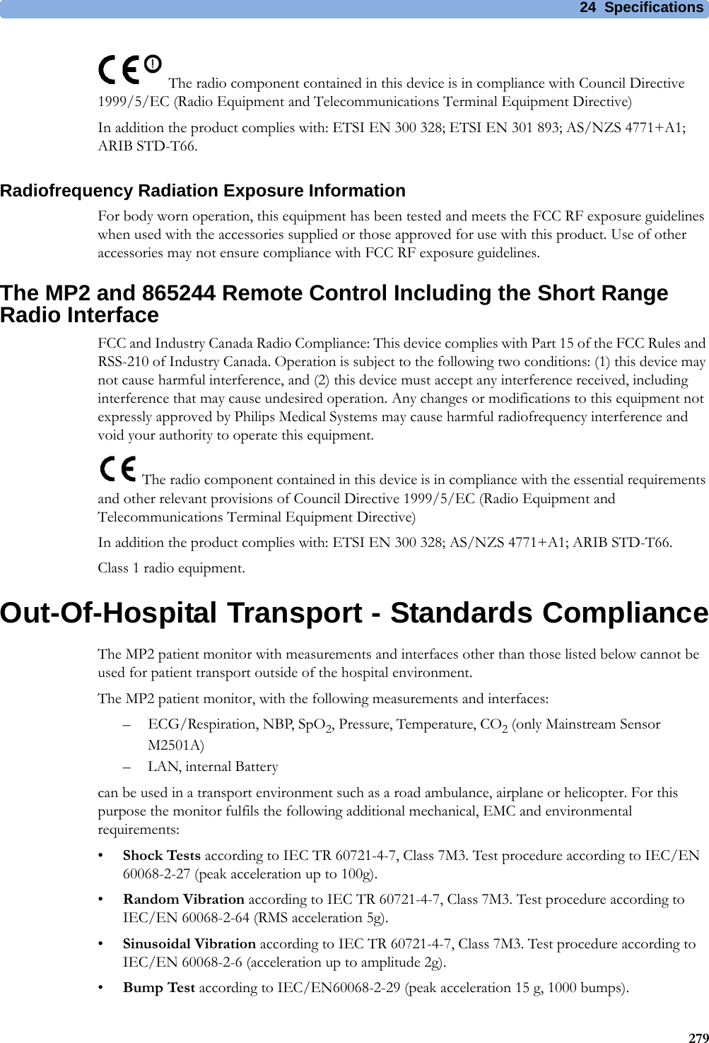
![5 Patient Alarms and INOPs78Resp INOPsNBP INOPsINOP Message, Indication What to do Resp Equip MalfNumeric is replaced by -?-INOP toneContact your service personnel. The RESP hardware is faulty.Resp ErraticNumeric is replaced by -?-The monitor has detected too many artifacts in the measured Resp signal. Check that the RA and LL electrodes are correctly attached and have not dried out.Resp Leads OffNumeric is replaced by -?-INOP toneNot all the required leads for Resp monitoring are attached. Make sure that the RA and LL leads are attached.INOP Message, Indication What to do !! Cuff Not Deflat!!!Cuff Not DeflatNumeric is displayed with a -?-Severe yellow/red INOP toneDuring this INOP, alarms cannot be paused or switched off.Remove the cuff from the patient. Make sure that the tubing is not kinked or twisted and that the correct patient category is selected. Try repeating the measurement. You can silence the INOP, but the INOP message remains visible until the next NBP measurement is started or the Stop All SmartKey is selected.[Adult or pediatric patients: The NBP cuff pressure has exceeded 15 mmHg (2 kPa) for more than 3minutes. Neonatal patients: The NBP cuff pressure has exceeded 5 mmHg (0.7 kPa) for more than 90 seconds.]!! Cuff Overpress!!!Cuff OverpressNumeric displayed with a -?-Severe yellow/red INOP toneDuring this INOP, alarms cannot be paused or switched off.The NBP cuff pressure exceeds the overpressure safety limits. Remove the cuff from the patient. Make sure that the tubing is not kinked or twisted and that the correct patient category is selected. Try restarting the measurement. You can silence this INOP, but the INOP message remains visible until the next measurement is started or the Stop All SmartKey is selected.NBP DeactivatedINOP toneThe NBP measurement label in the measurement device has been deactivated by deactivating the label in the Measurement Selection window. The measurement automatically disappears from the display. To switch the measurement on again, reactivate the measurement label in the Measurement Selection window.NBP Equip MalfNumeric is replaced by -?- INOP toneRemove the cuff from the patient. The NBP hardware is faulty. Contact your service personnel. You can silence this INOP, but the INOP message remains visible until the next measurement is started or the Stop All SmartKey is selected.NBP InterruptedNumeric is replaced by -?- INOP toneCheck the tubing and cuff for leakages or kinks. Check that you are using the correct cuff size and placement, and that the correct patient category is selected. Try restarting the measurement. If the INOP occurs repeatedly, contact your service personnel.You can silence this INOP, but the INOP message remains visible until the next measurement is started or the Stop All SmartKey is selected.This INOP arises when the measurement needed longer than the maximum time for inflation, deflation or the total measurement.NBP Measure FailedNumeric may be displayed with a-?- INOP toneCheck that you are using the correct cuff size and placement, and that the correct patient category is selected. Try restarting the measurement.You can silence this INOP, but the INOP message remains visible until the next measurement is started or the Stop All SmartKey is selected.Check the condition and suitability of the patient for NBP monitoring. Use another cuff to continue measuring.](https://usermanual.wiki/Philips-Medical-Systems-North-America/WLANBV2.User-Manual-IntelliVue-MP2/User-Guide-2137734-Page-78.png)
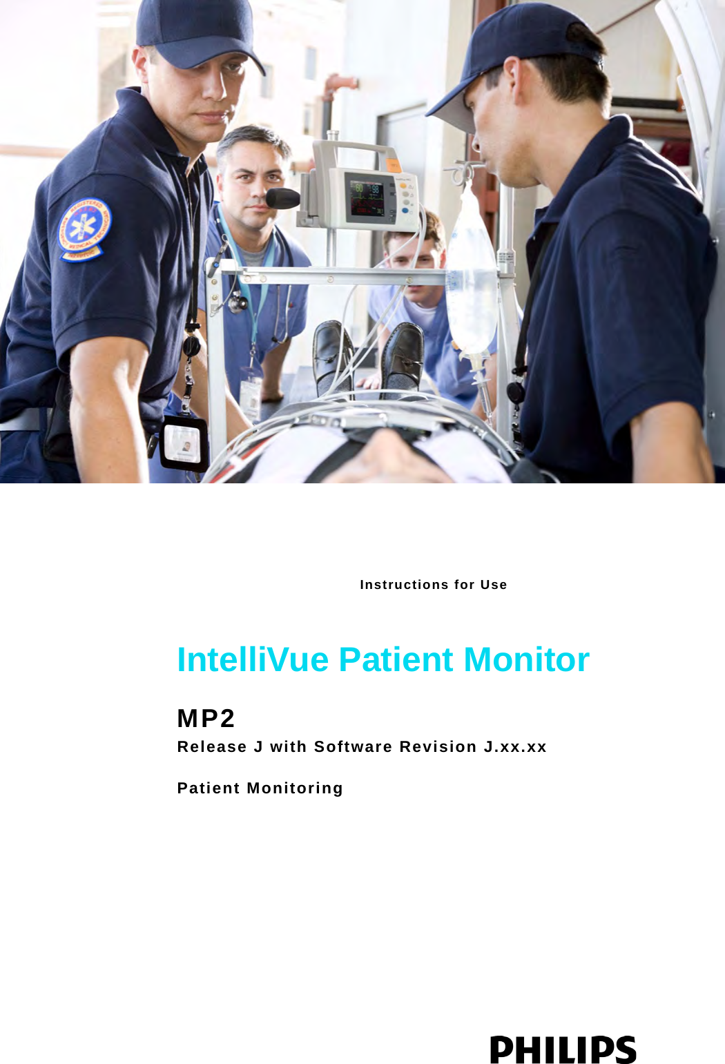
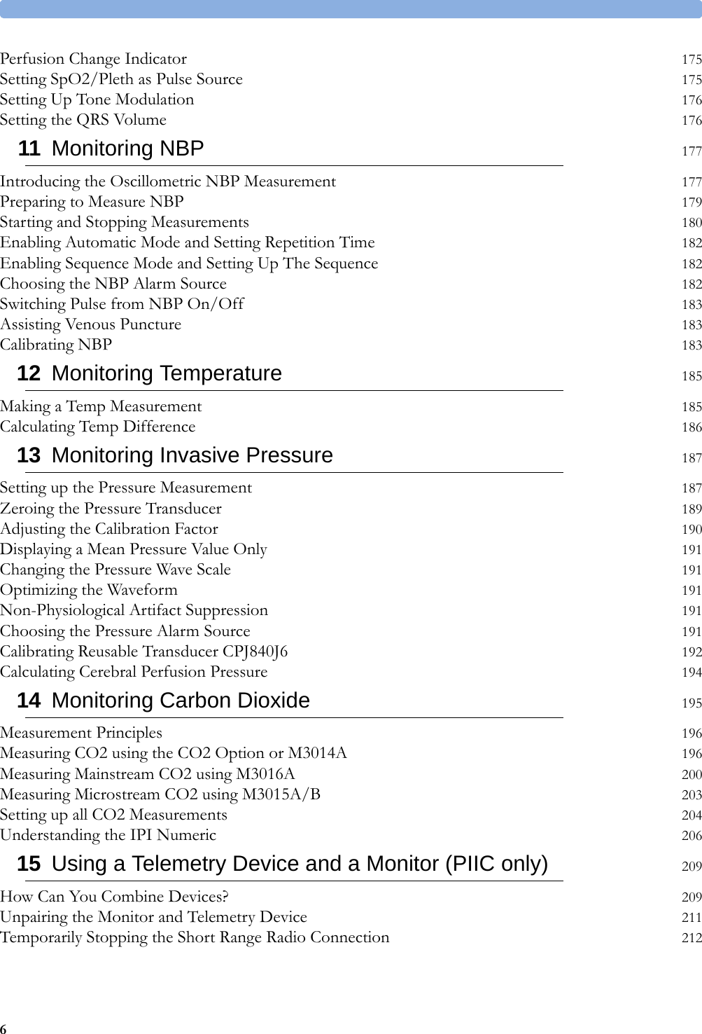
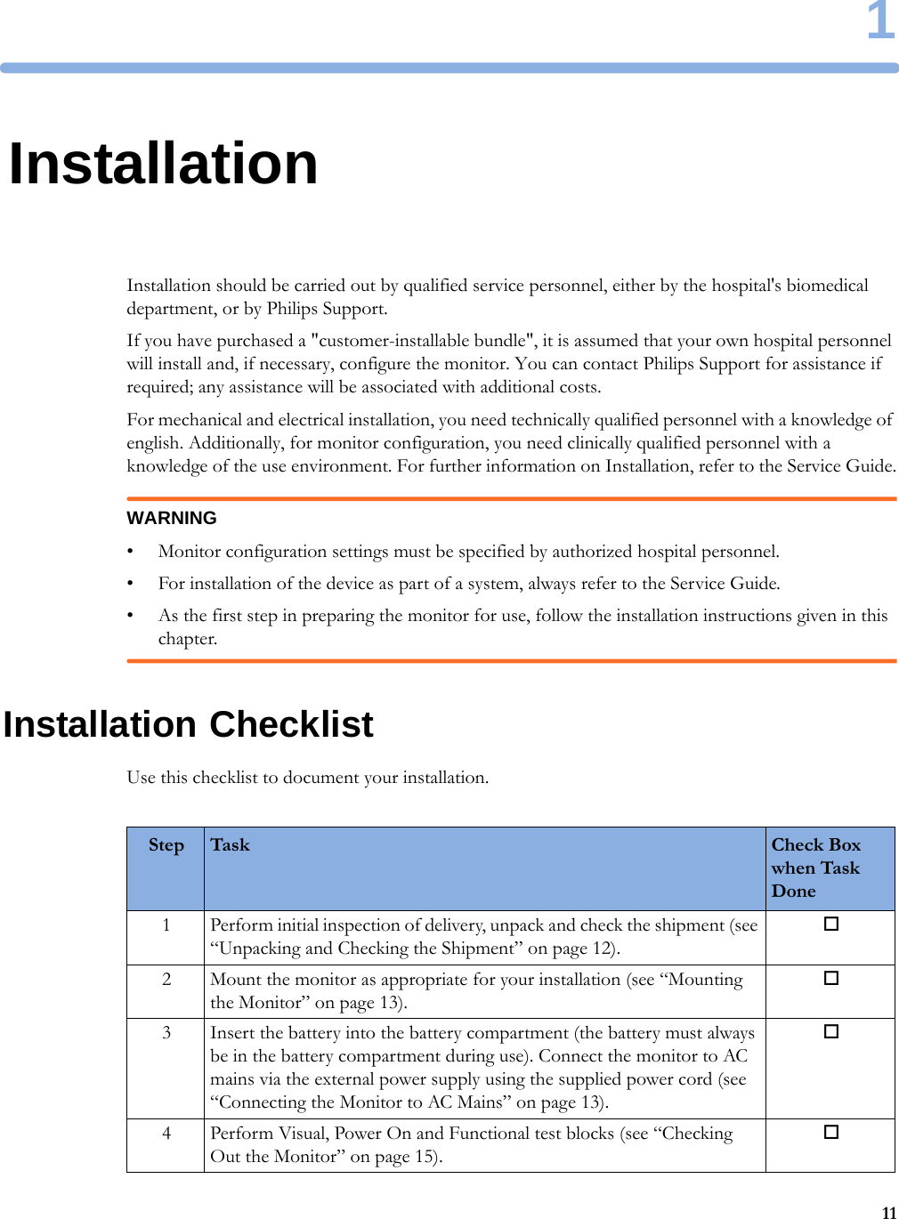
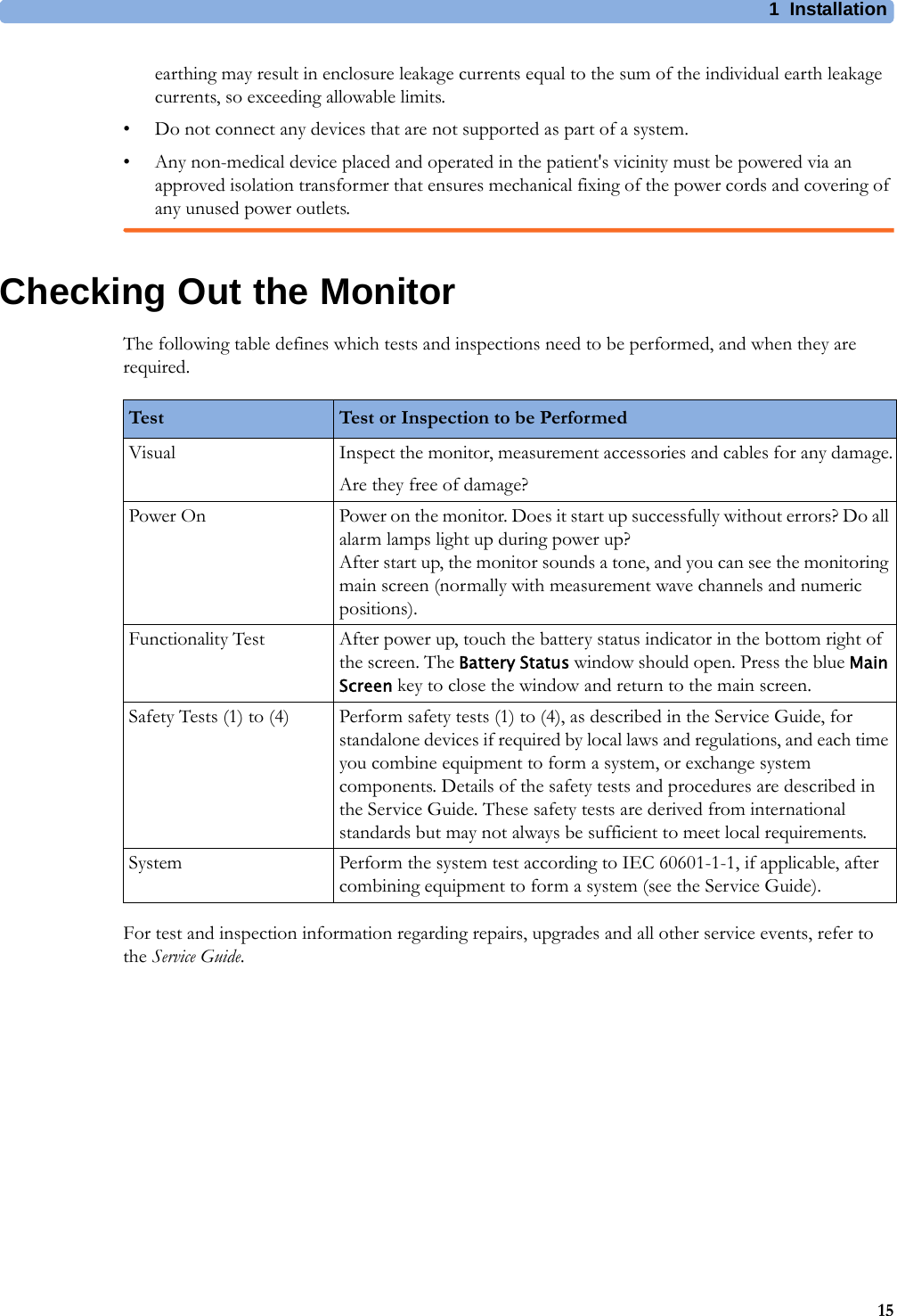
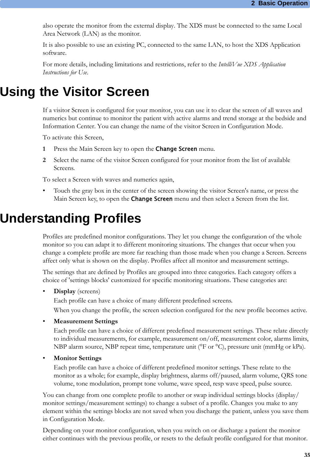
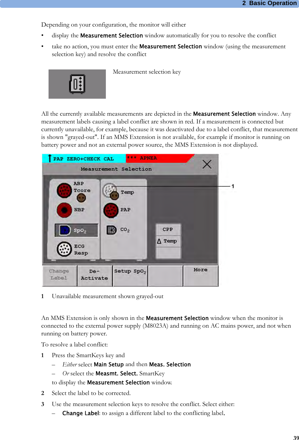
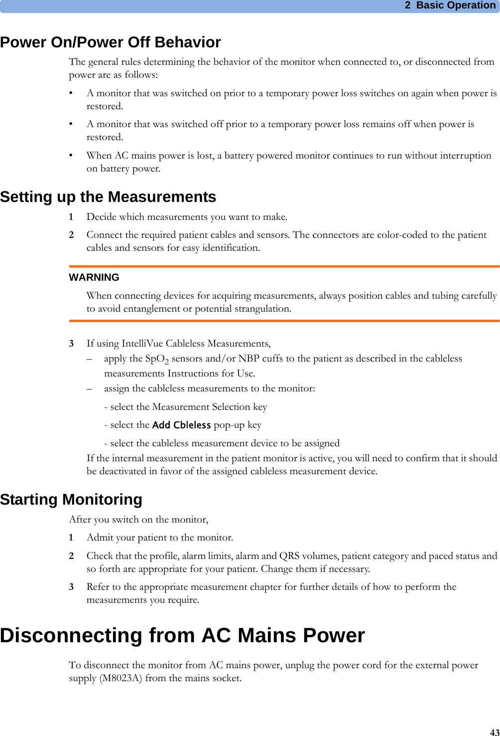
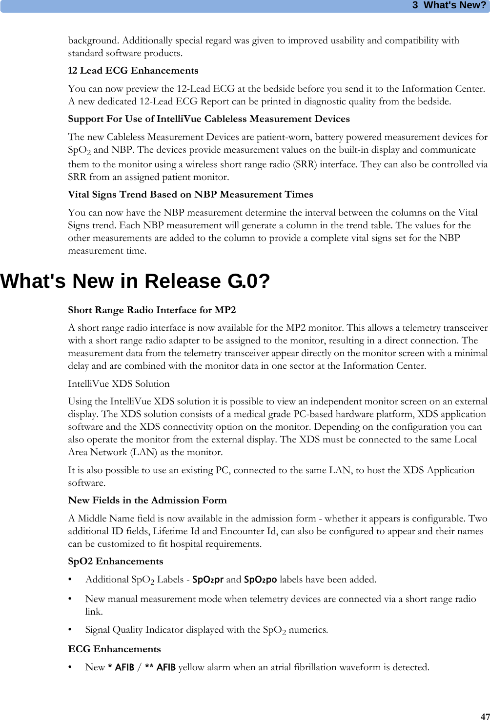
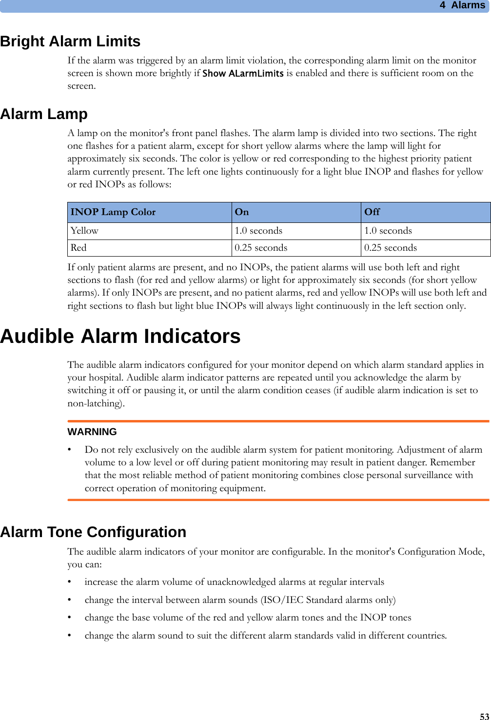
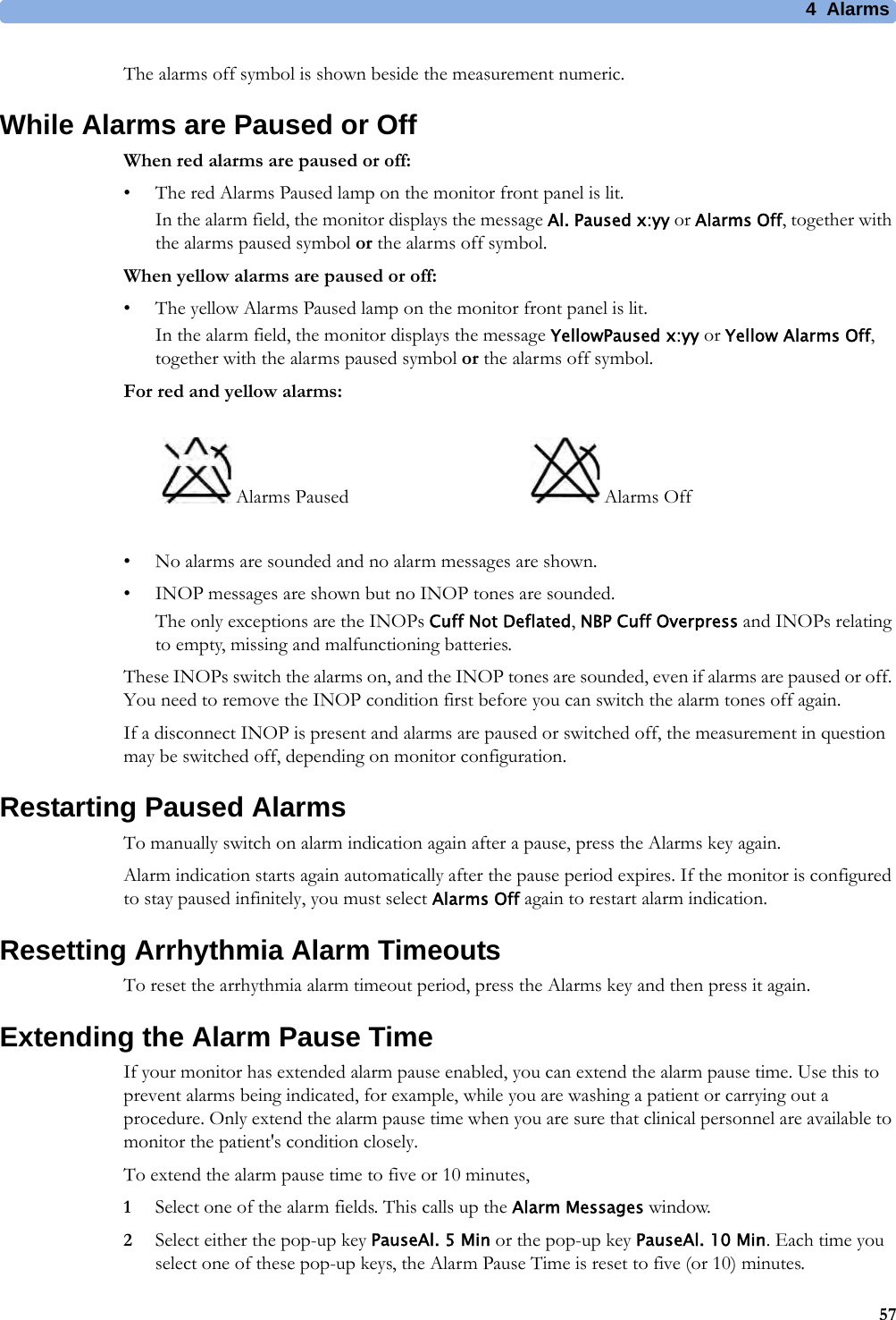
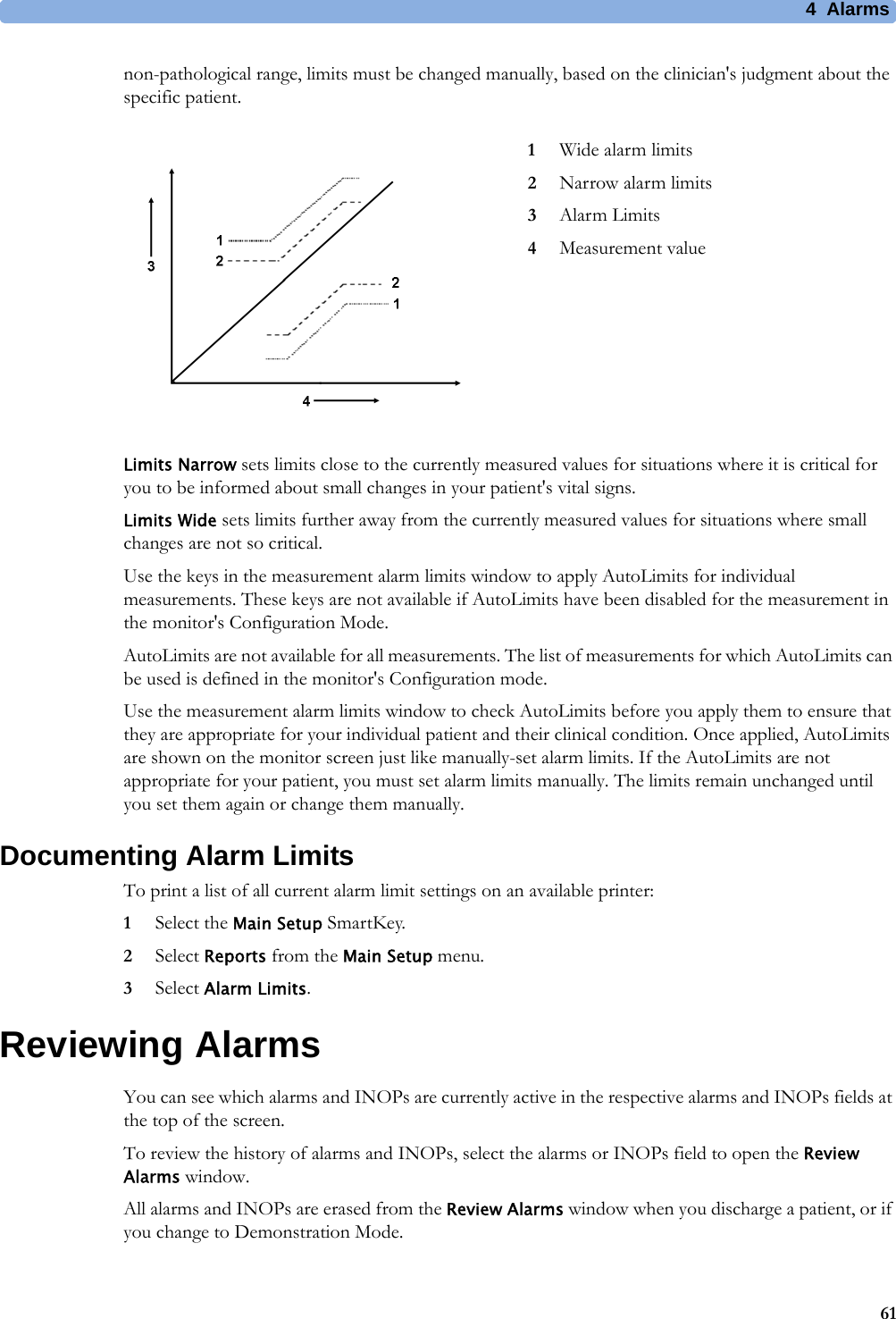
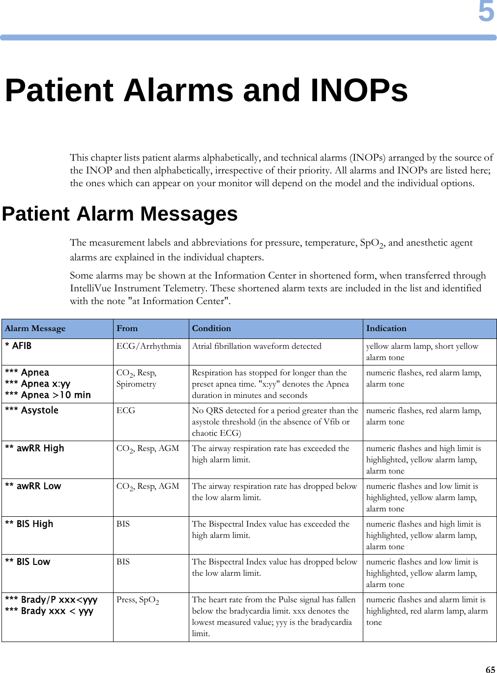
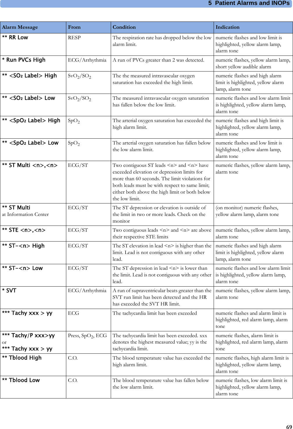
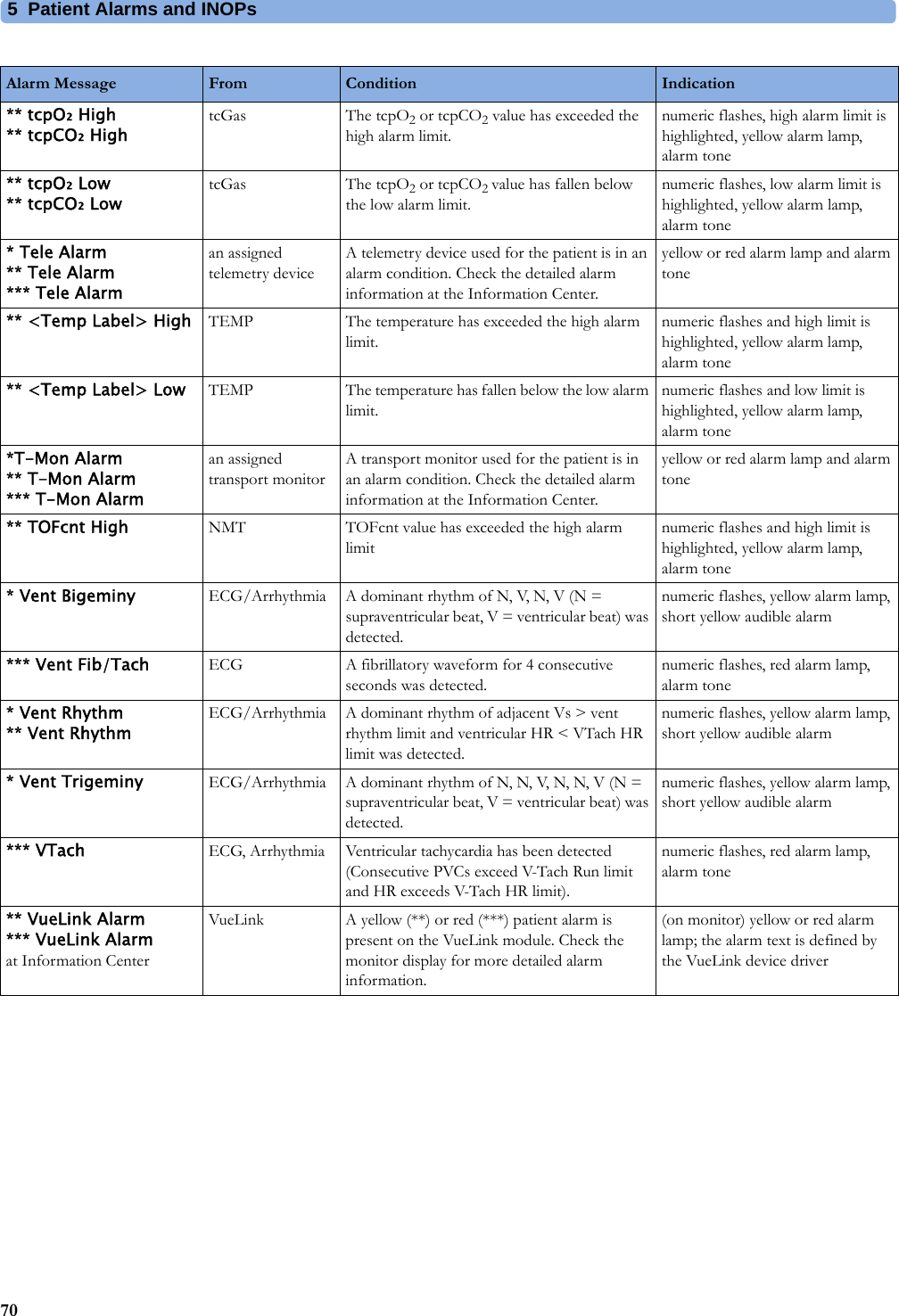
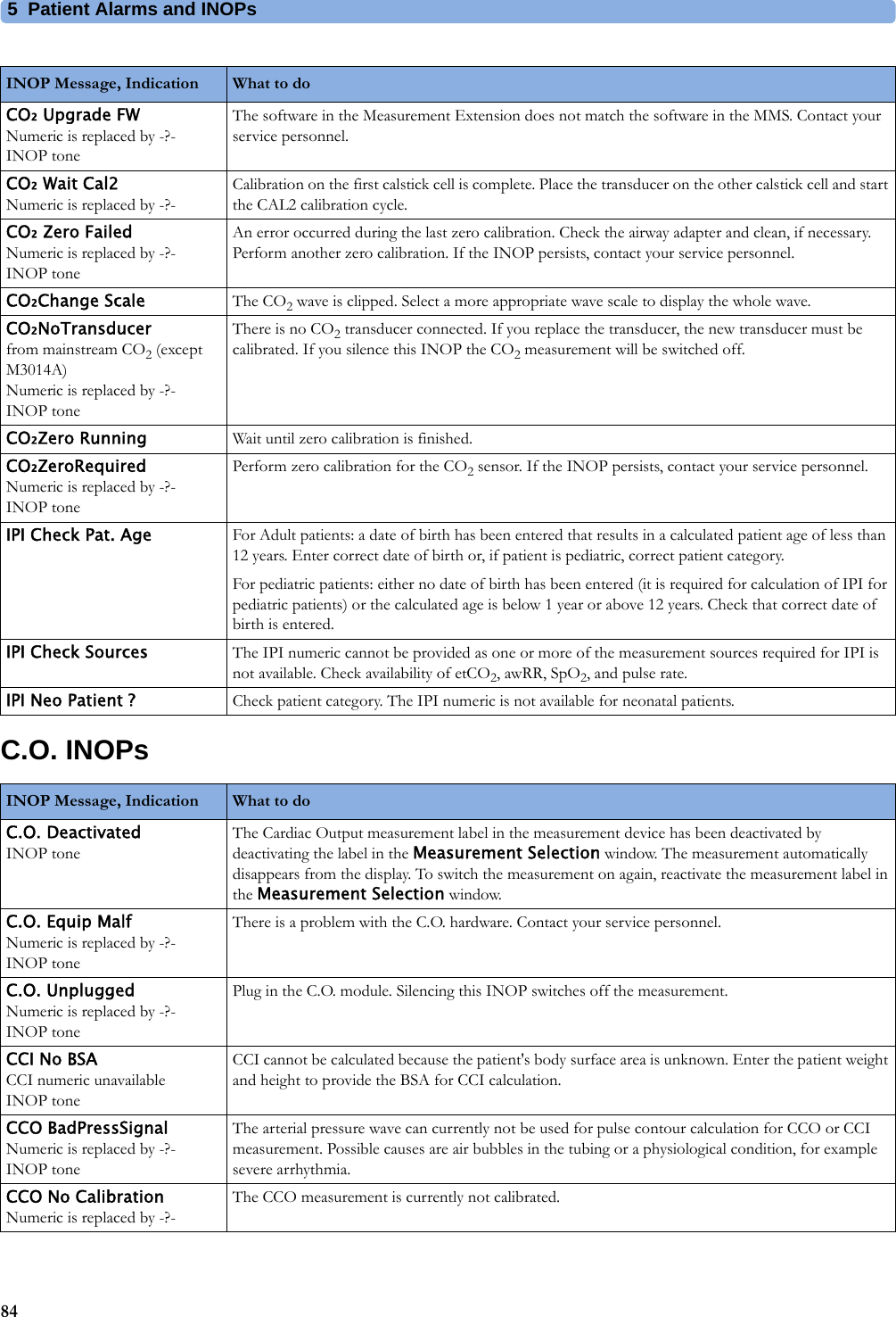
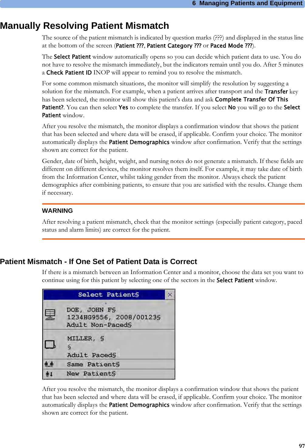
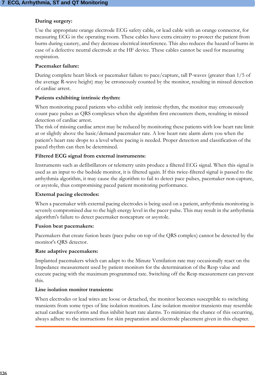
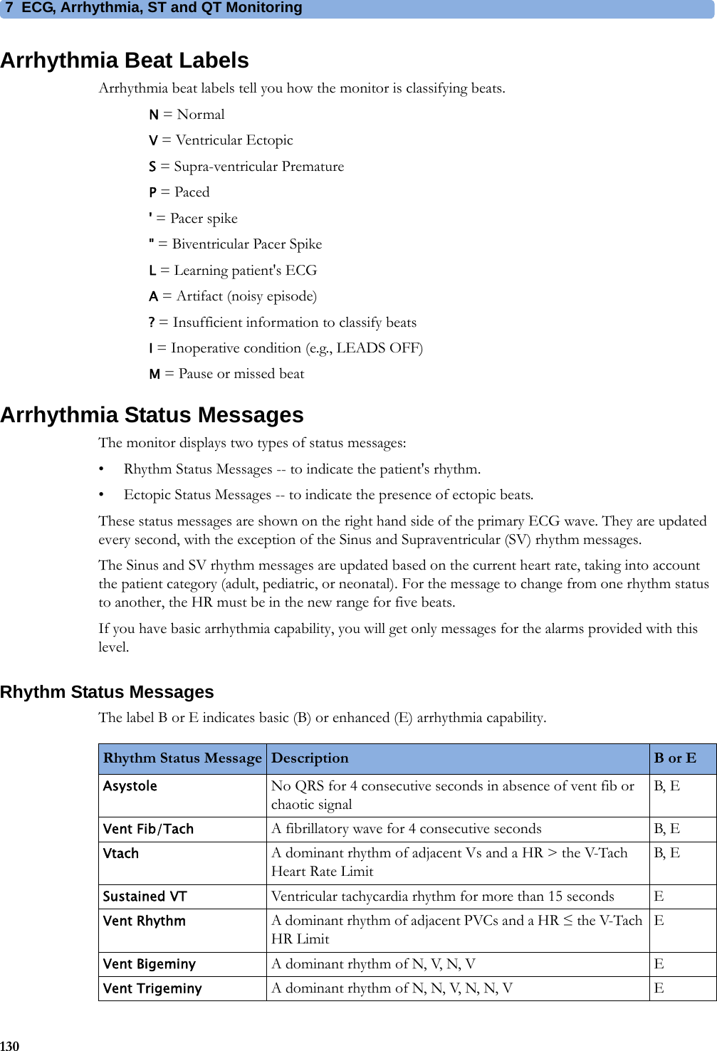
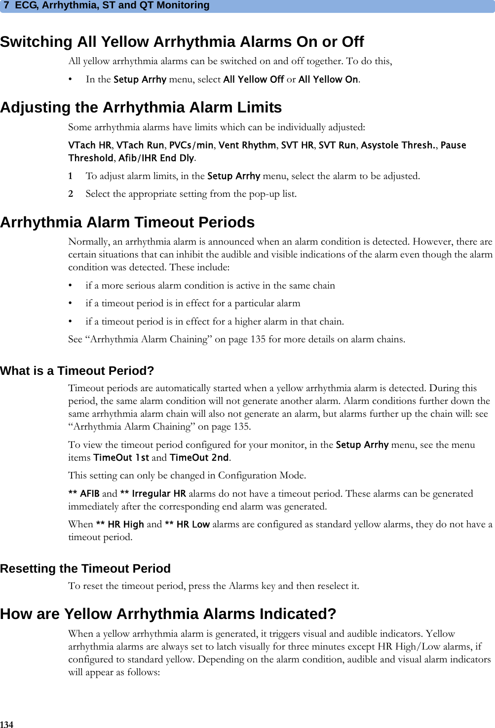
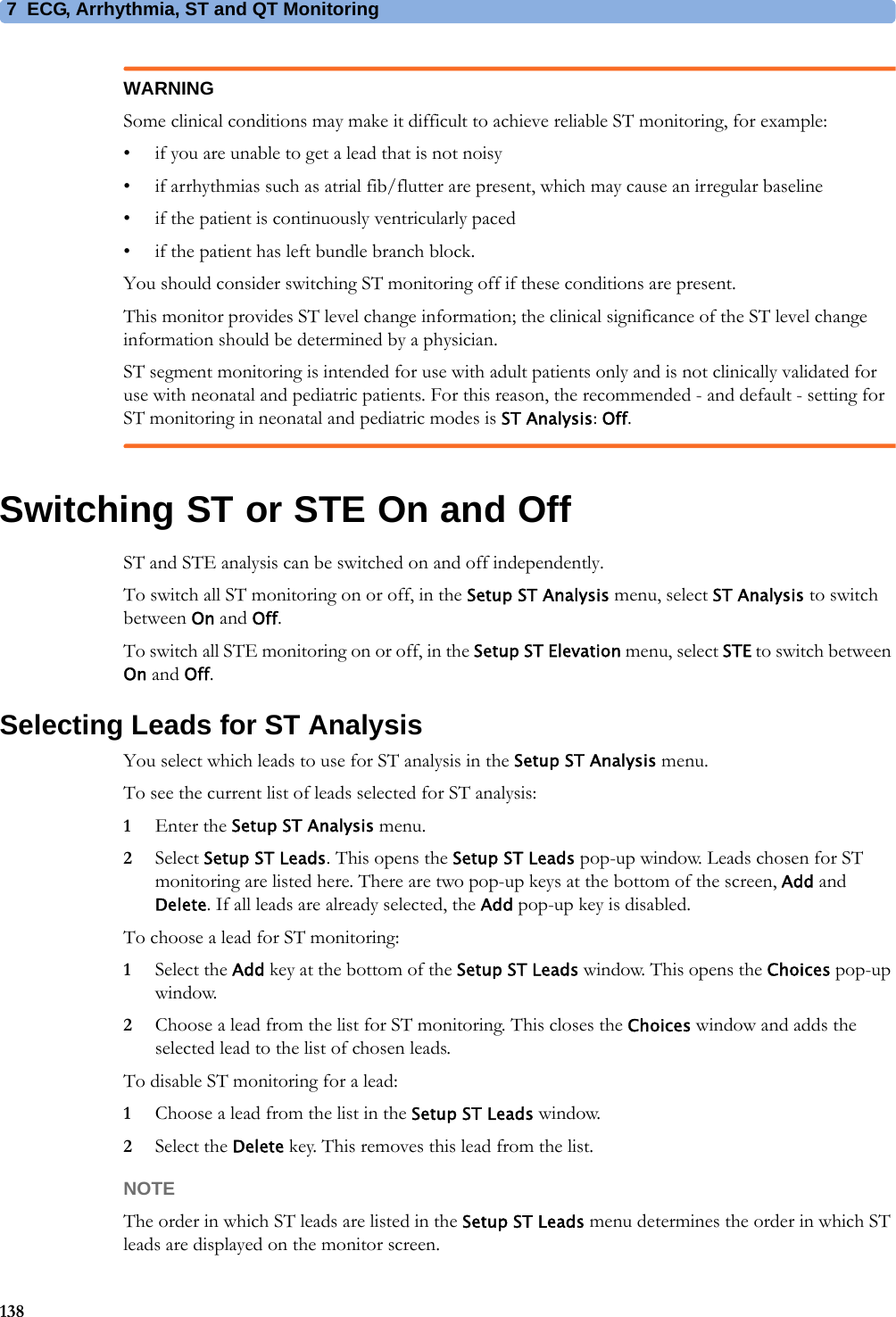
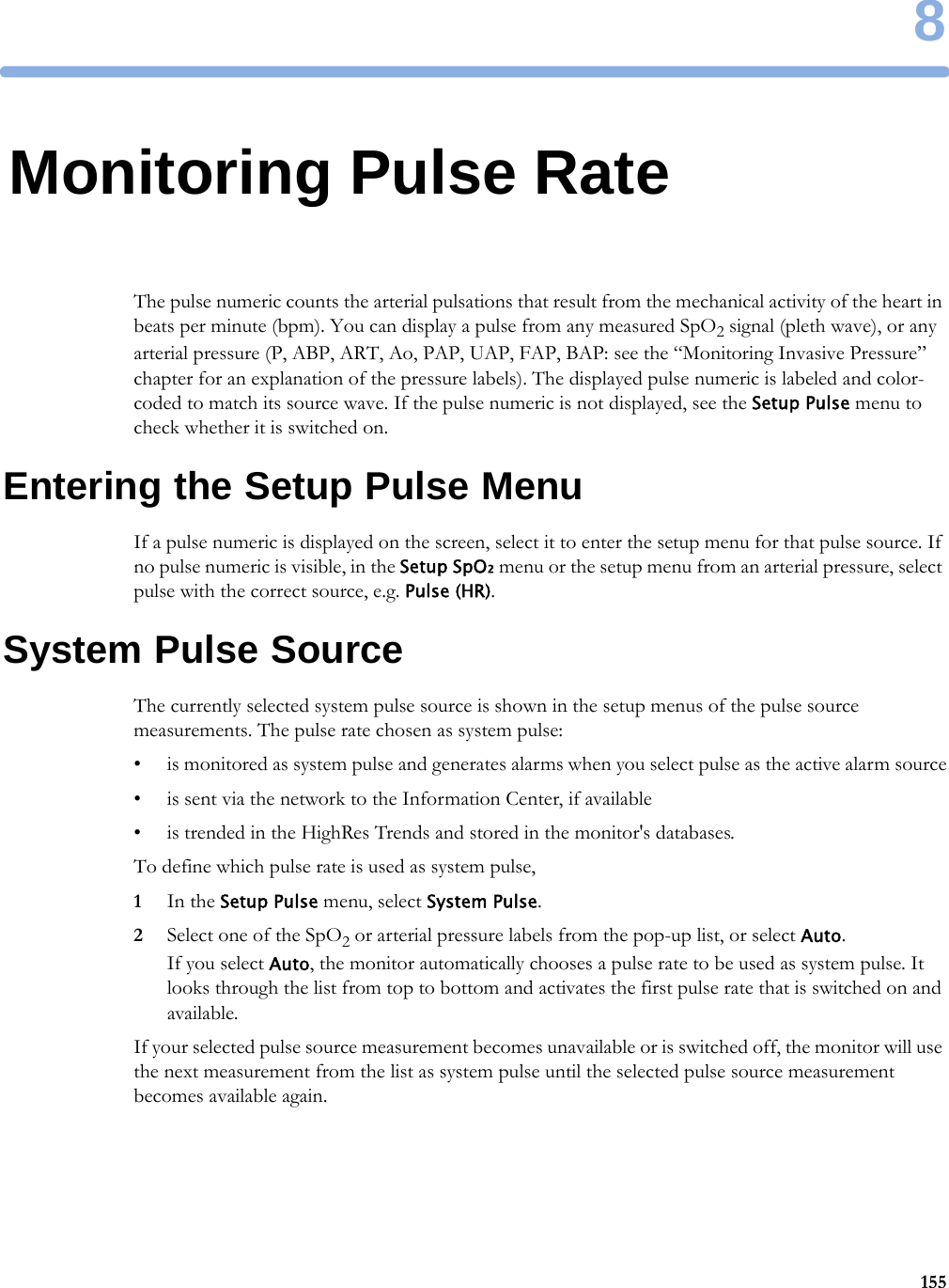
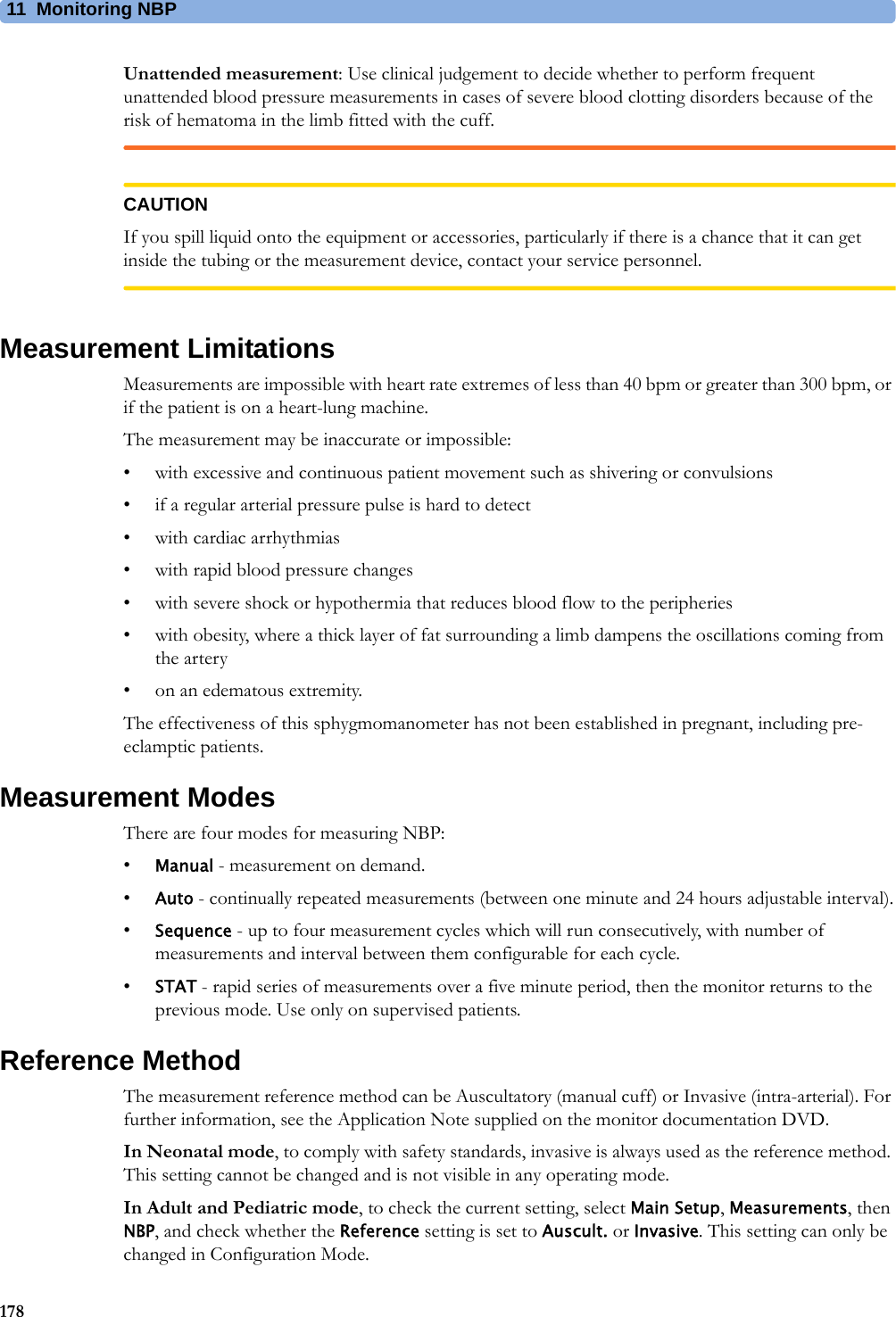
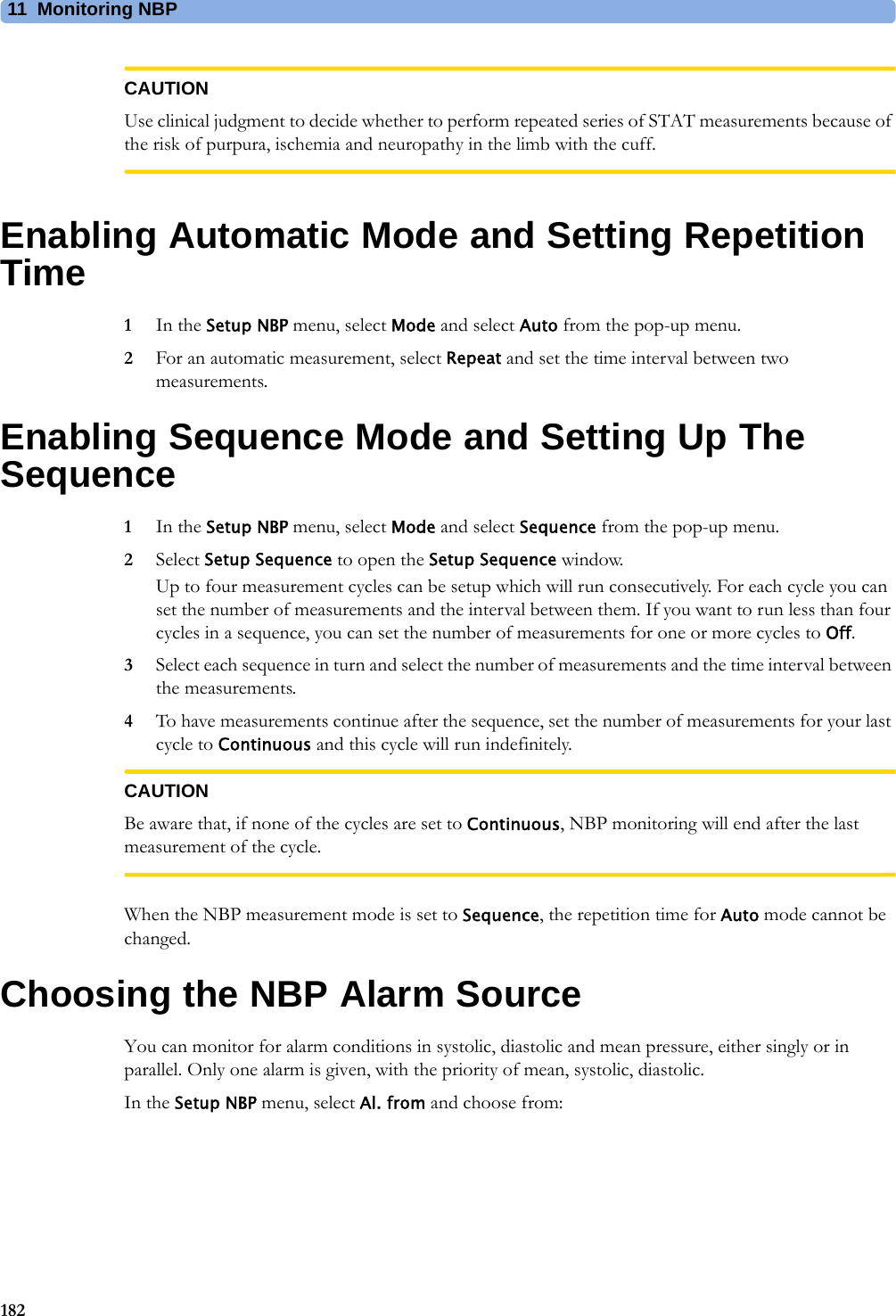
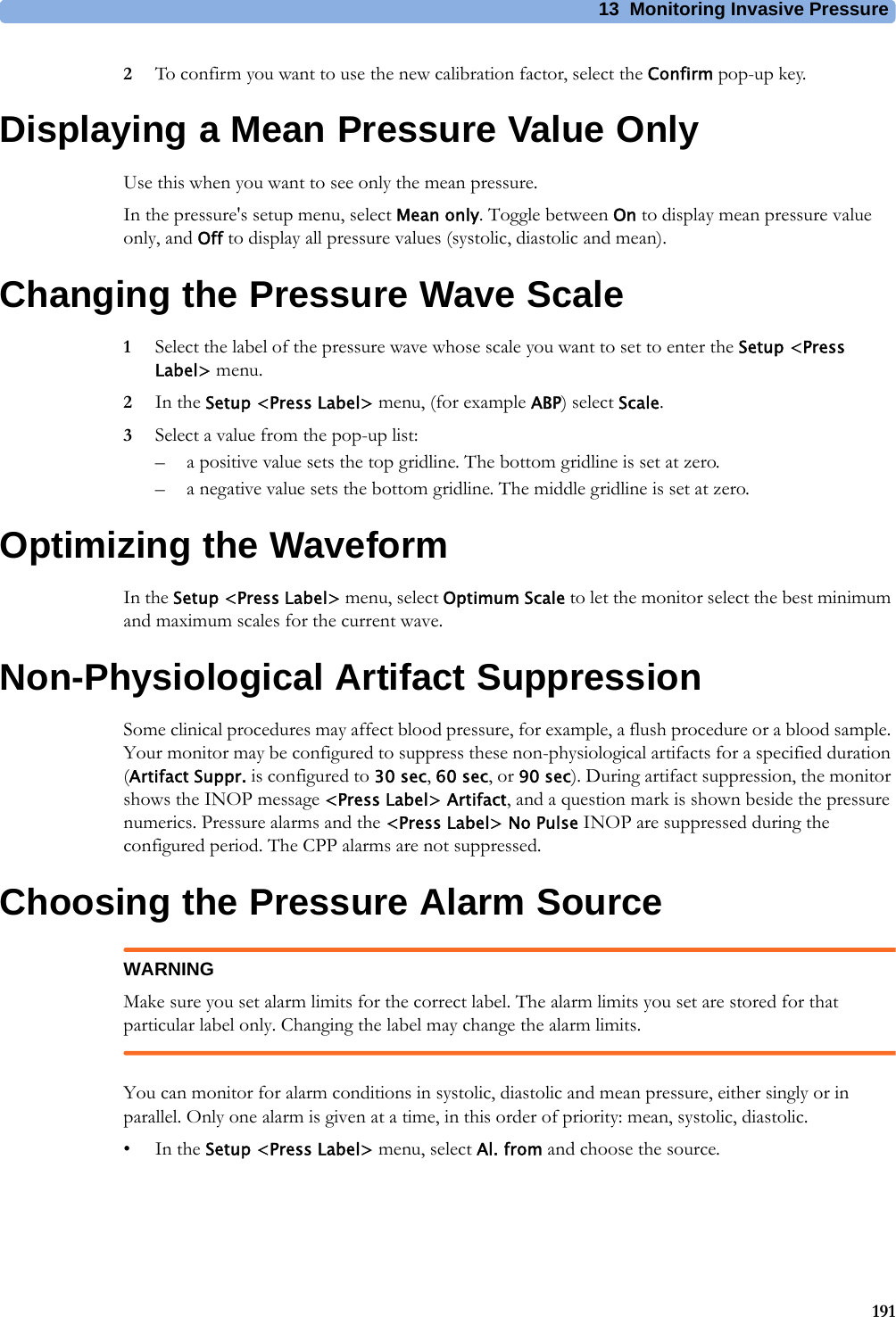
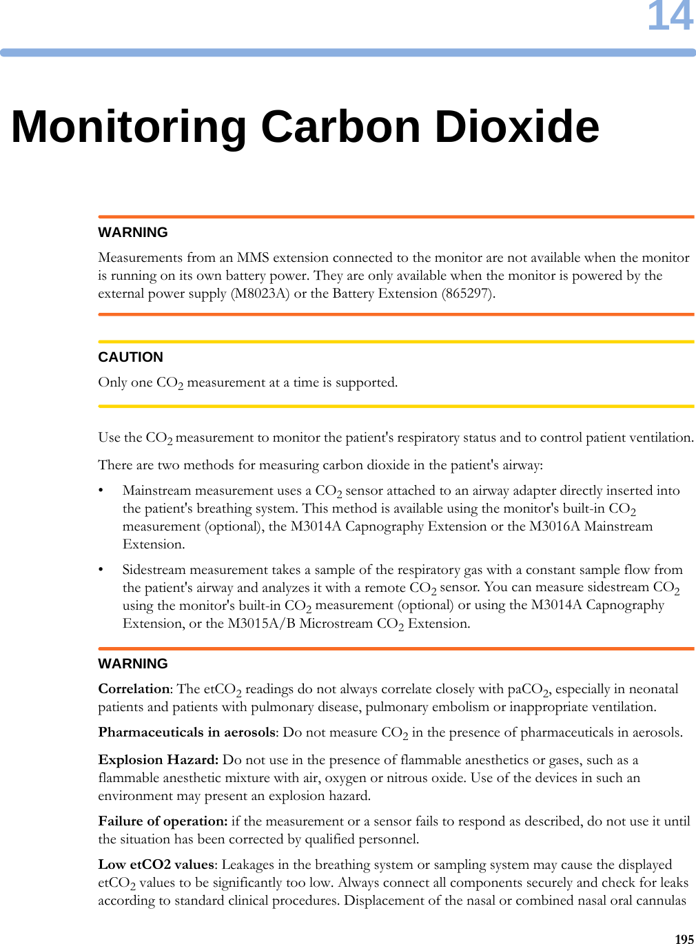
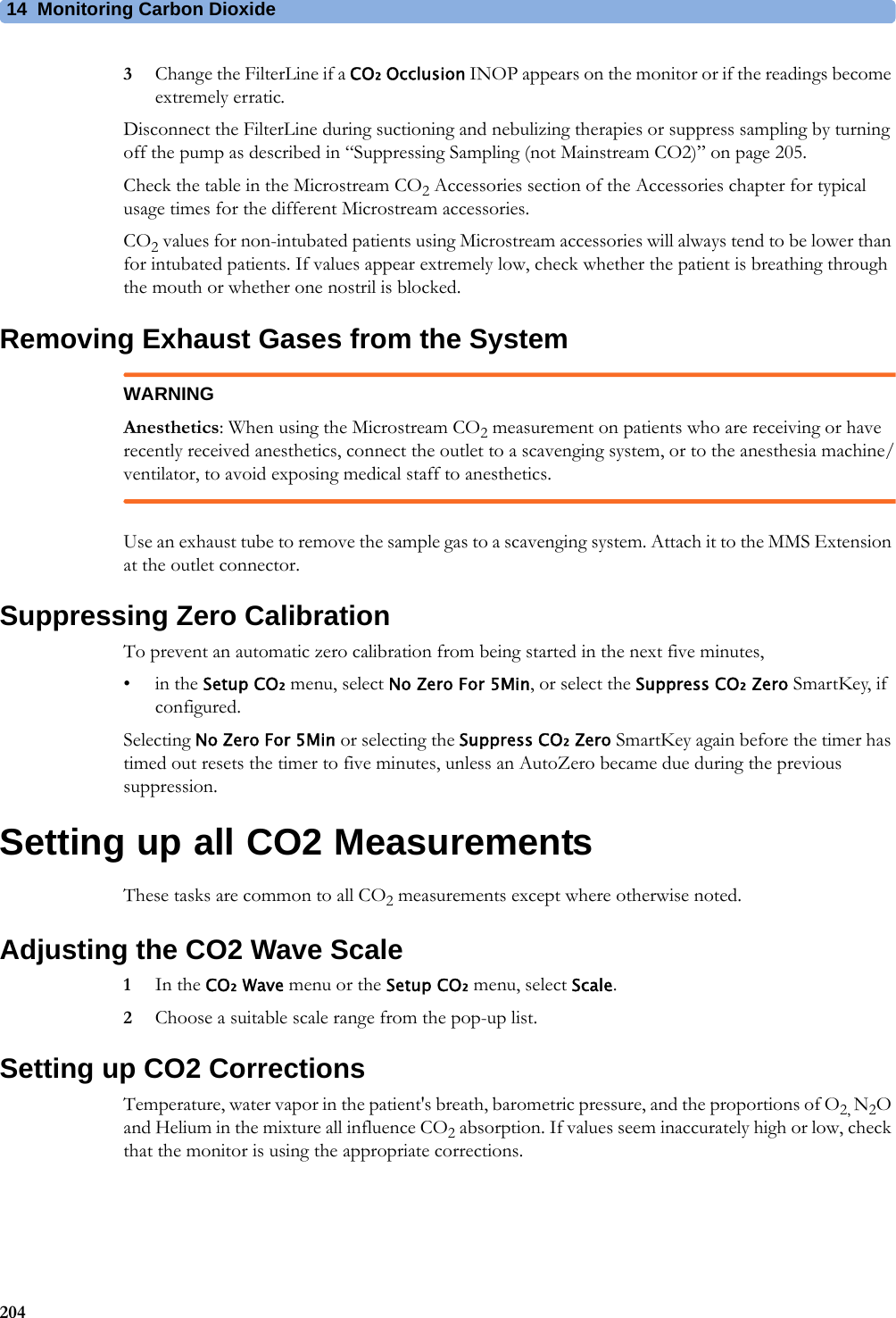
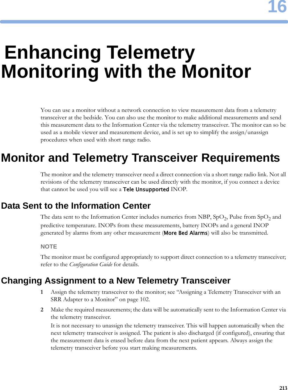
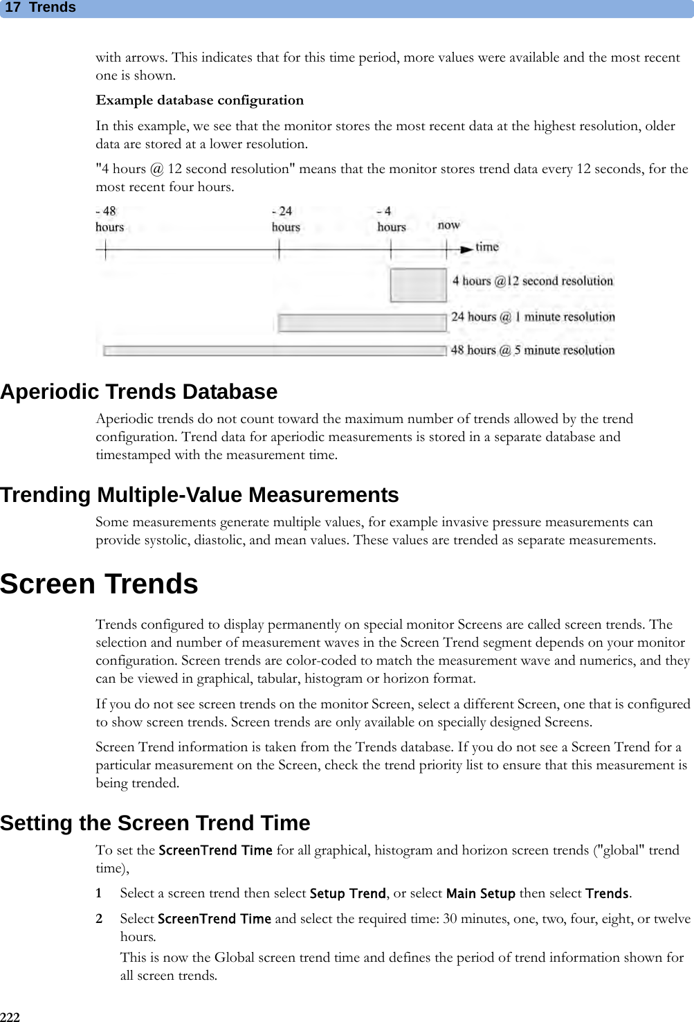
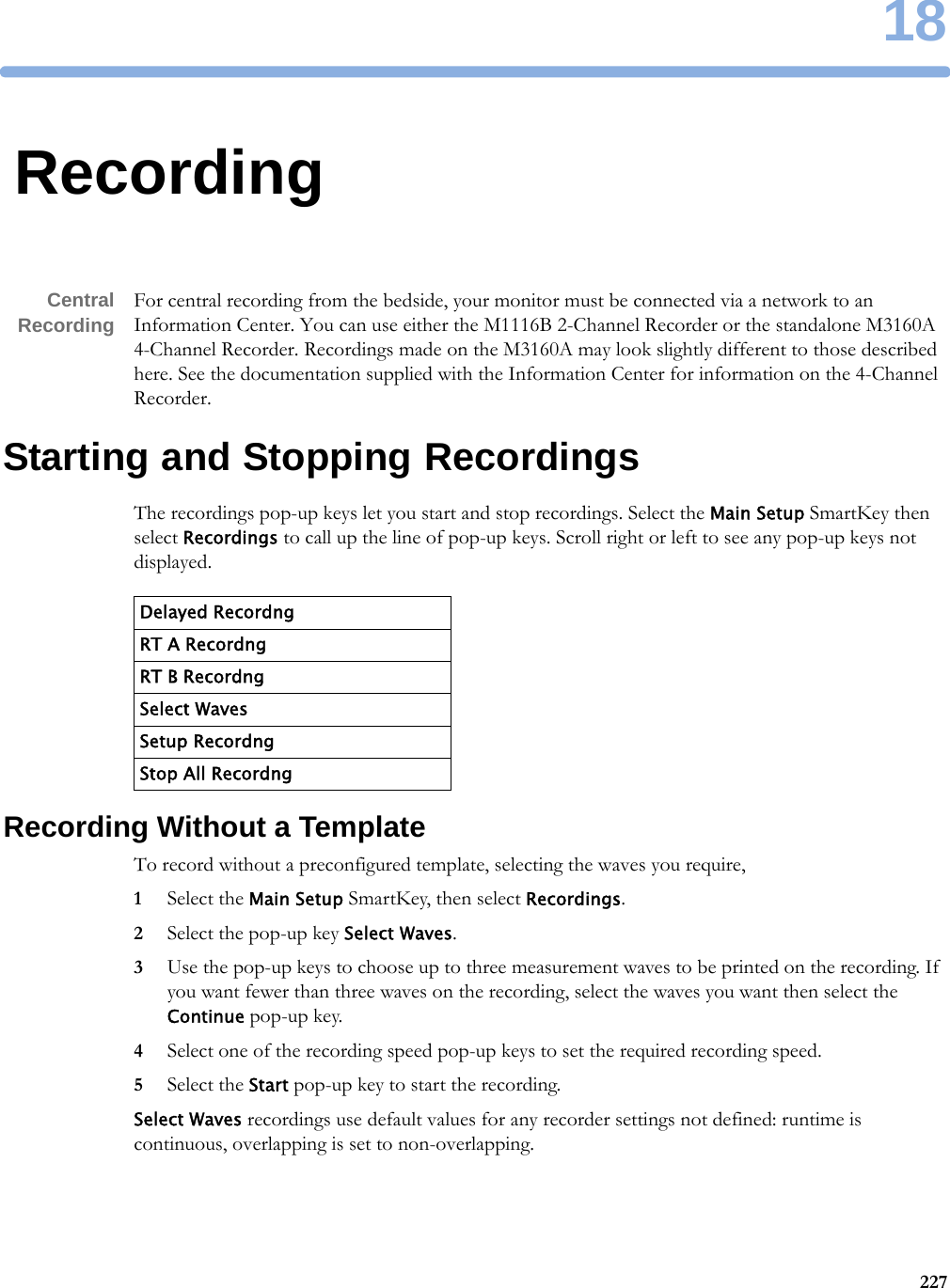
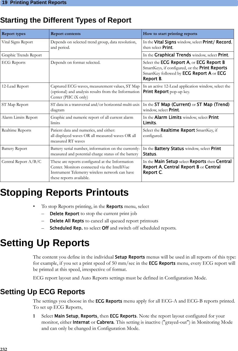
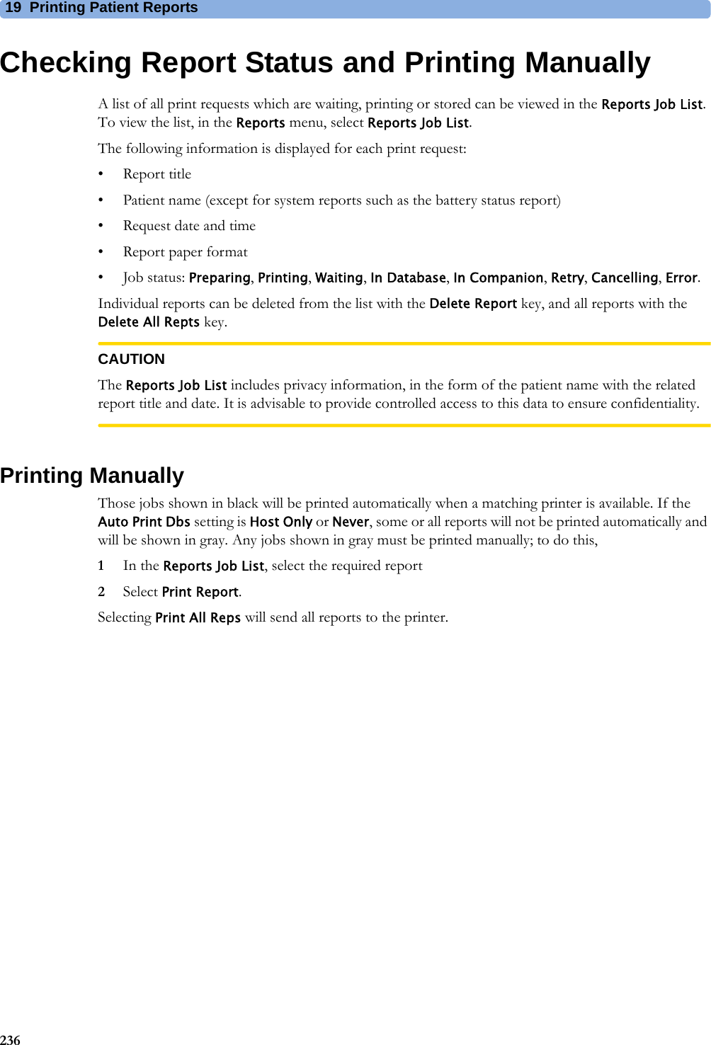
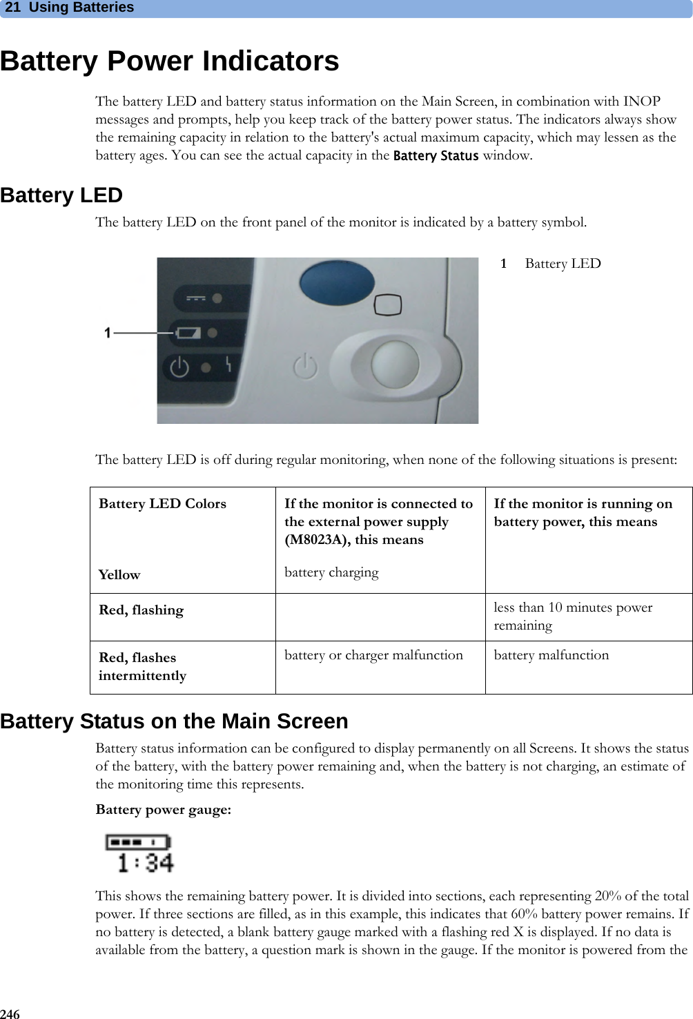
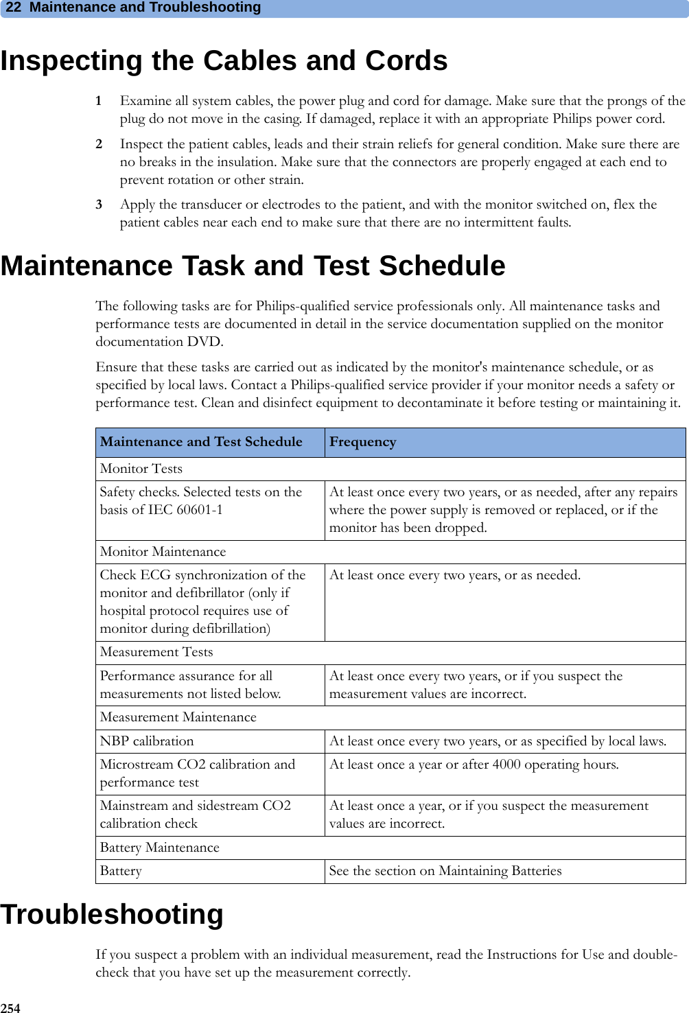
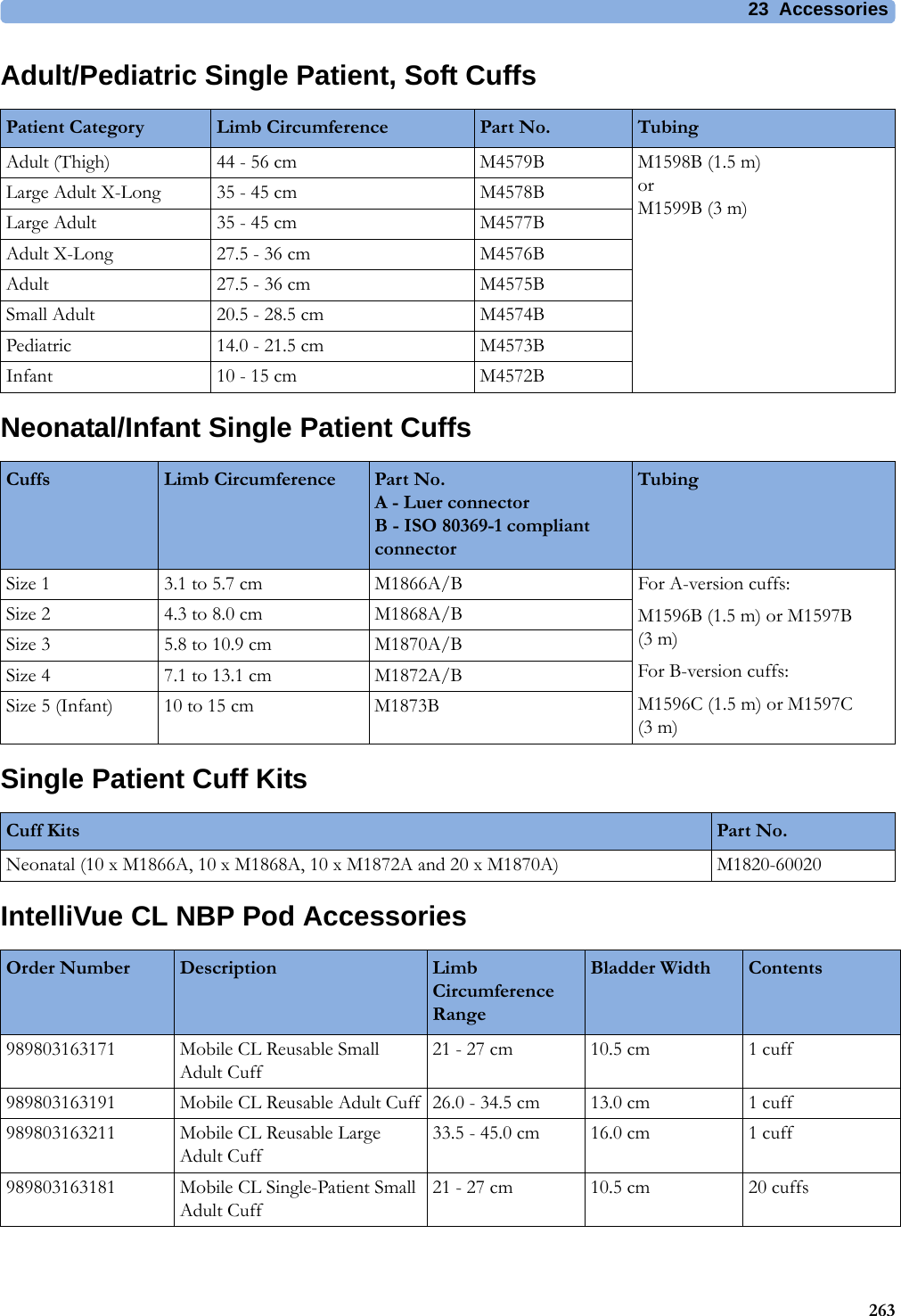
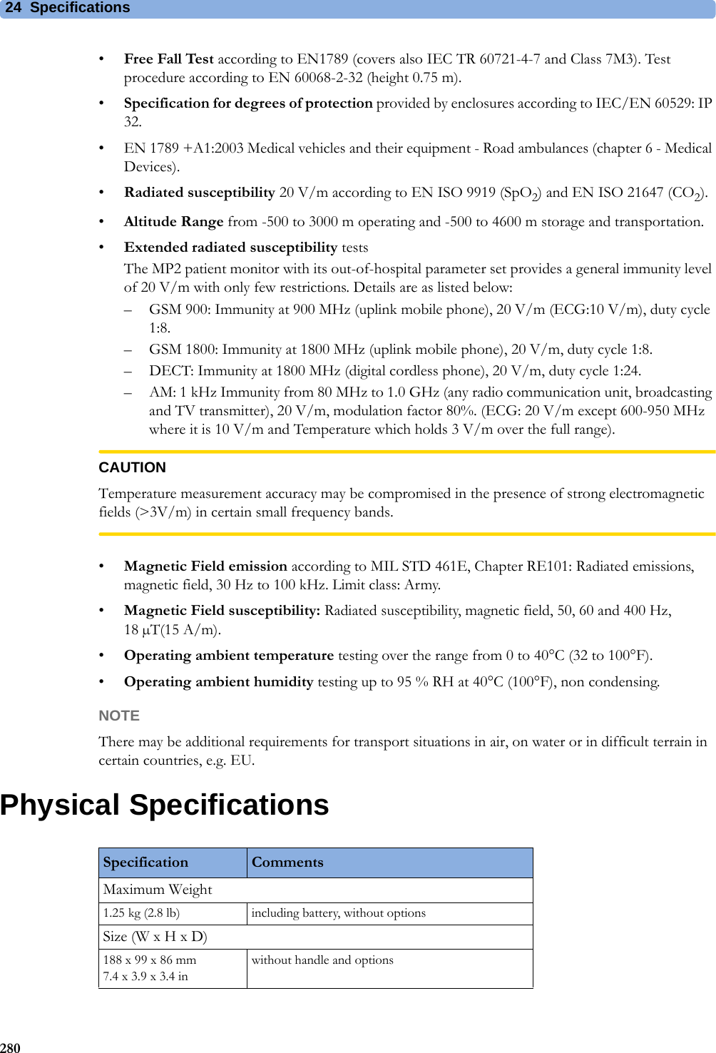
![5 Patient Alarms and INOPs79Temperature INOPsINOP Message, Indication What to do T1, T2, T3, T4 INOPs See <Temp Label> INOPsTamb INOPs See <Temp Label> INOPsTart INOPs See <Temp Label> INOPsTcereb INOPs See <Temp Label> INOPsTcore INOPs See <Temp Label> INOPs<Temp Label> DeactivatedINOP toneA Temp measurement label in the measurement device has been deactivated, either by connecting a Pressure transducer in the shared Press/Temp socket, or by deactivating the label in the Measurement Selection window.The measurement automatically disappears from the display.To switch the measurement on again, either reconnect a Temp transducer or reactivate the measurement label in the Measurement Selection window.<Temp Label> Equip MalfNumeric is replaced by -?-INOP toneContact your service personnel.The temperature hardware is faulty.<Temp Label> OverrangeNumeric is replaced by -?-INOP toneTry changing the application site of the transducer.[The temperature is less than -1°C, or greater than 45°C.]<Temp Label> UnpluggedINOP toneA Temp measurement label has been deactivated, either by unplugging a module, or by deactivating the label in the Measurement Selection window.The measurement automatically disappears from the display.To switch the measurement on again, either replug the module or reactivate the measurement label in the Measurement Selection window.<Temp Label>NoTransducerNumeric is replaced by -?-INOP toneMake sure the TEMP probe is connected to the MMS or module.If you silence this INOP, the measurement will be switched off.Tesoph INOPs See <Temp Label> INOPsTnaso INOPs See <Temp Label> INOPsTrect INOPs See <Temp Label> INOPsTskin INOPs See <Temp Label> INOPsTtymp INOPs See <Temp Label> INOPsTven INOPs See <Temp Label> INOPsTvesic INOPs See <Temp Label> INOPs](https://usermanual.wiki/Philips-Medical-Systems-North-America/WLANBV2.User-Manual-IntelliVue-MP2/User-Guide-2137734-Page-79.png)
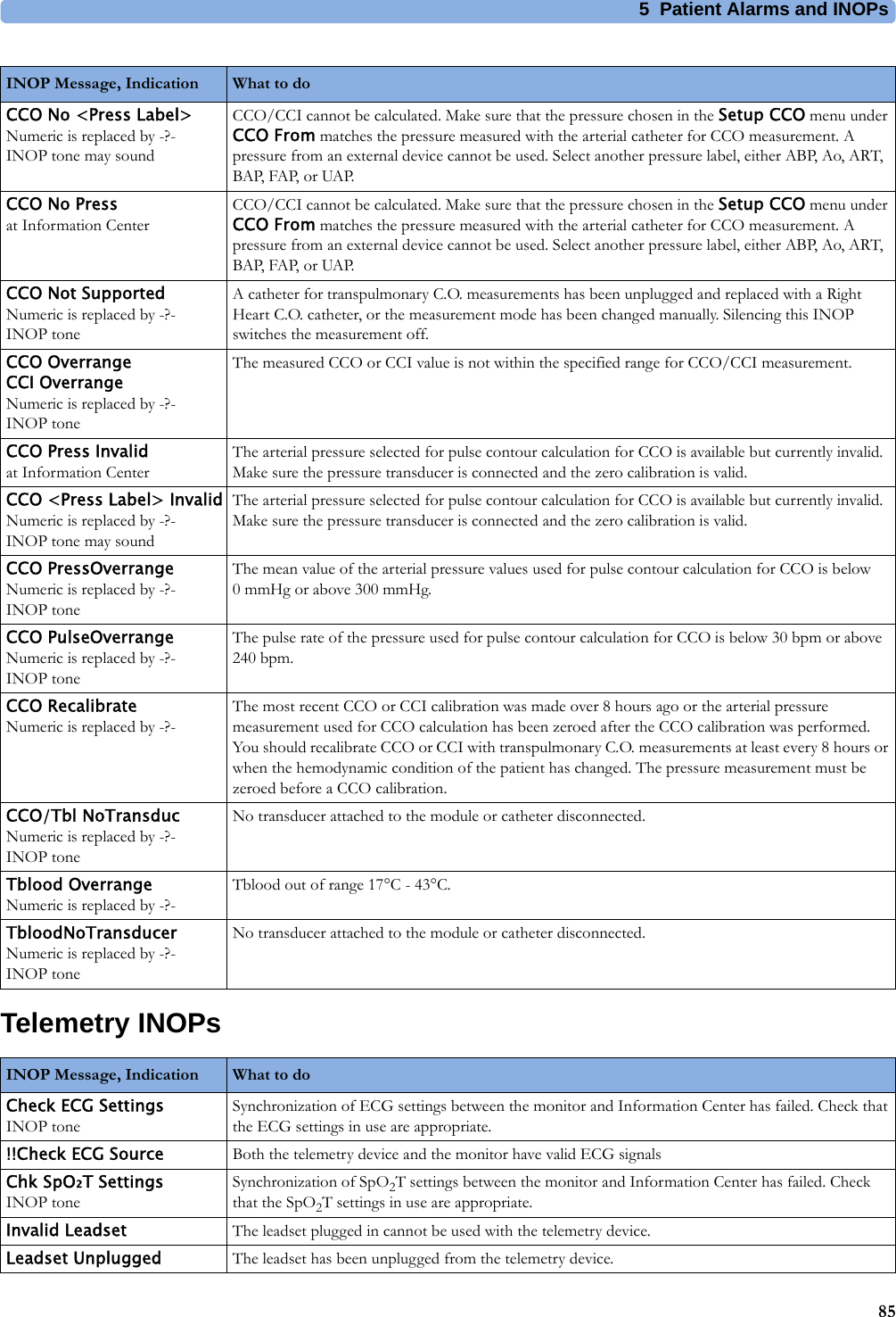

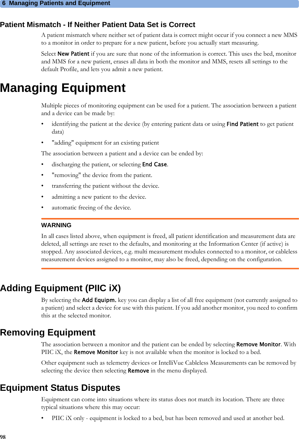
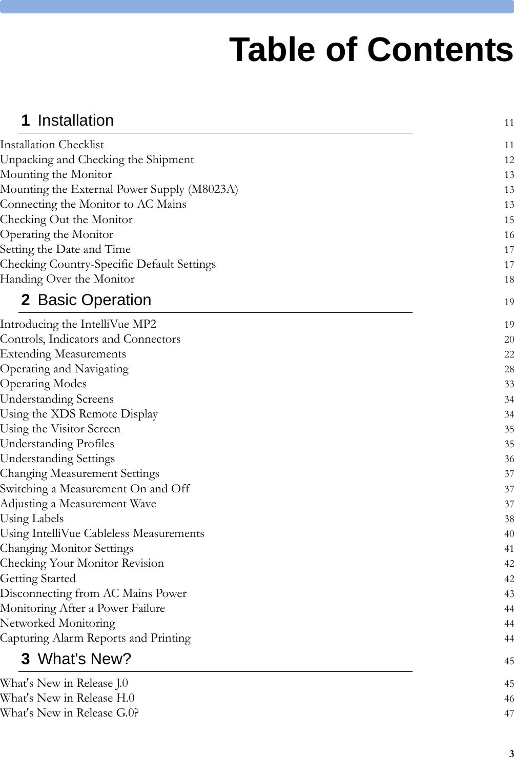
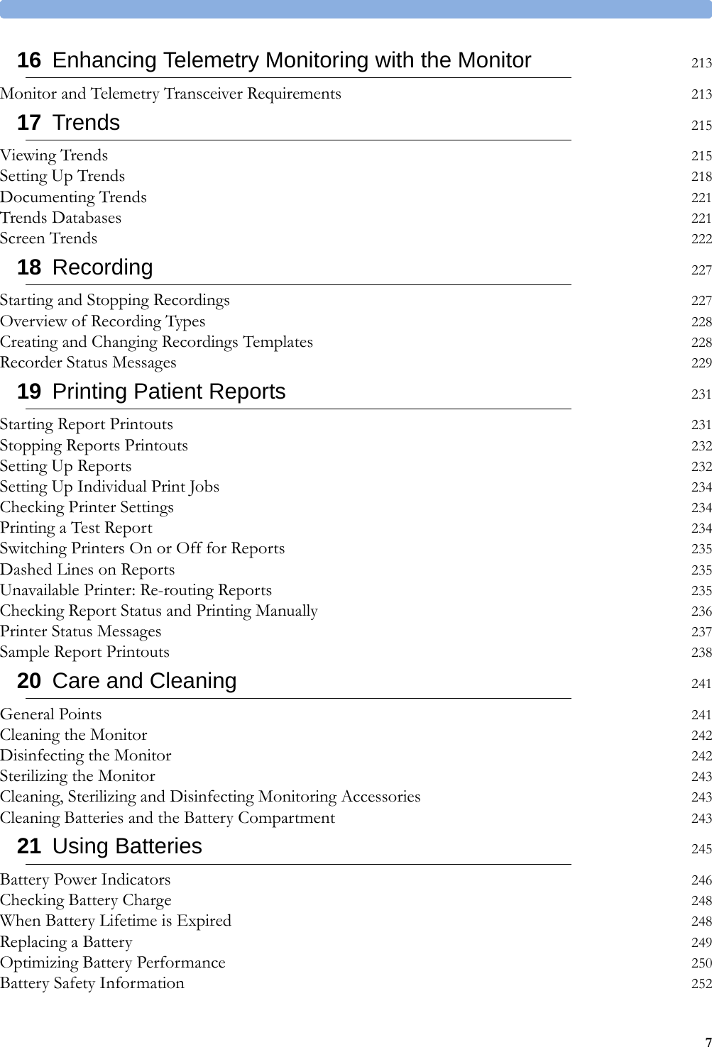
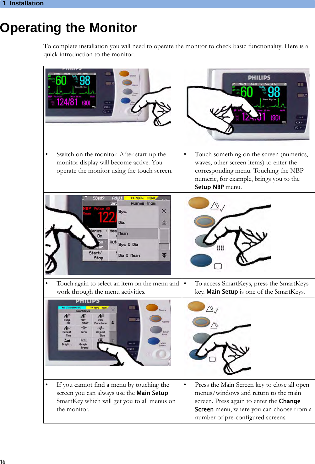
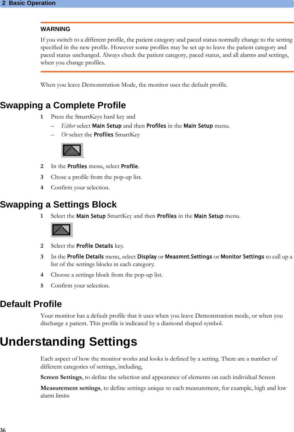
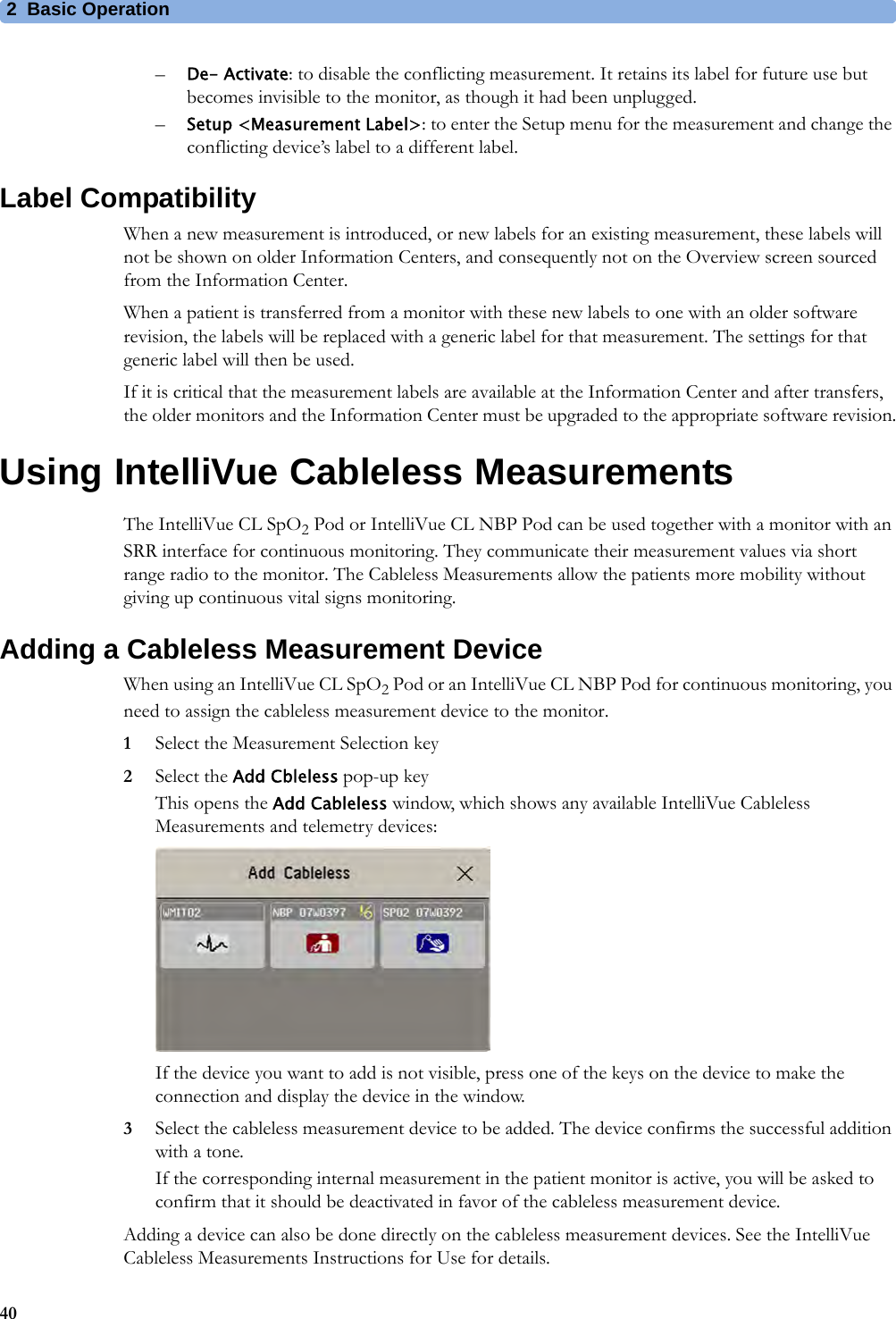
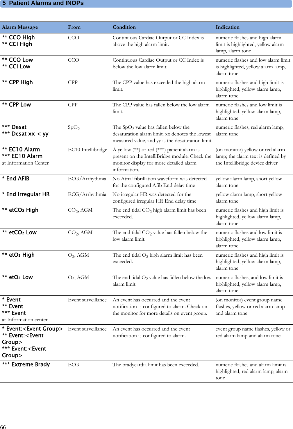
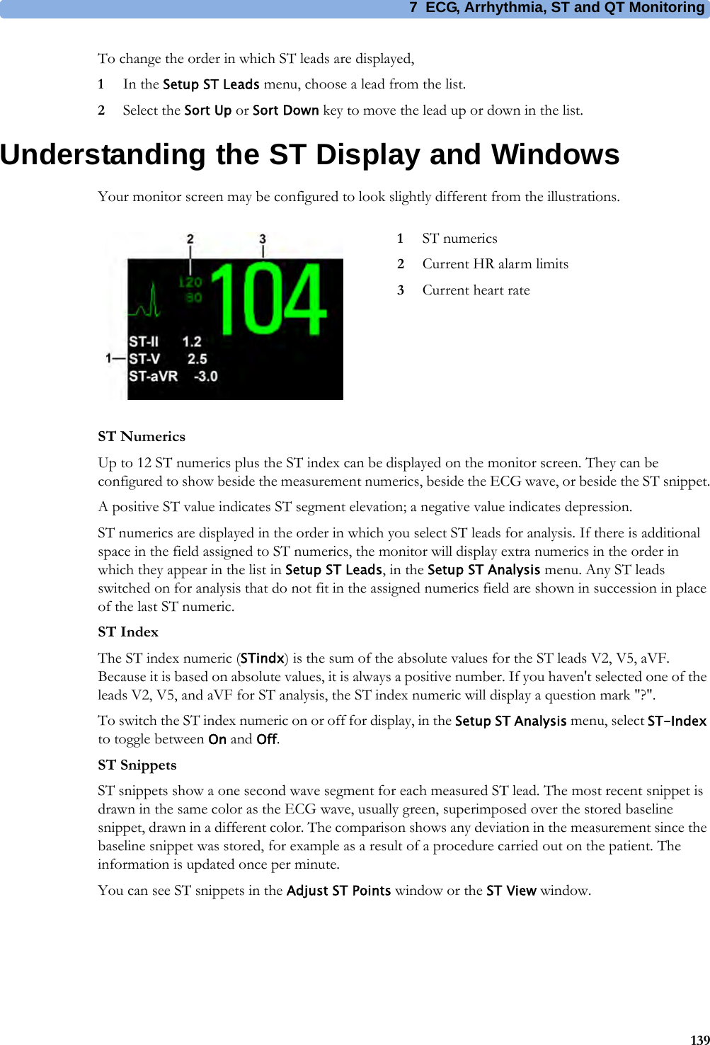
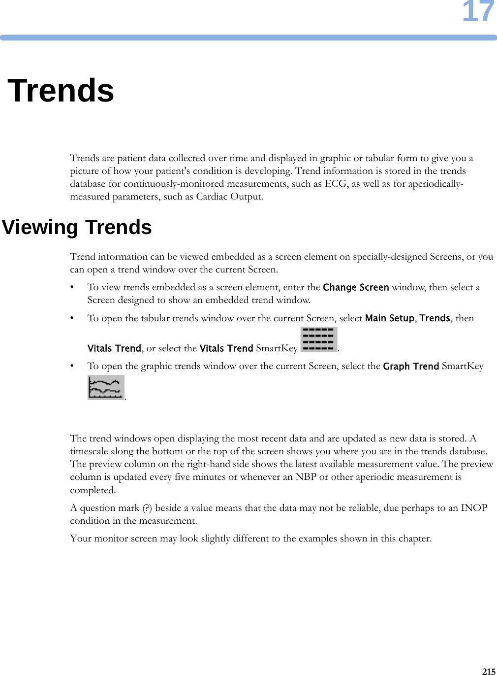
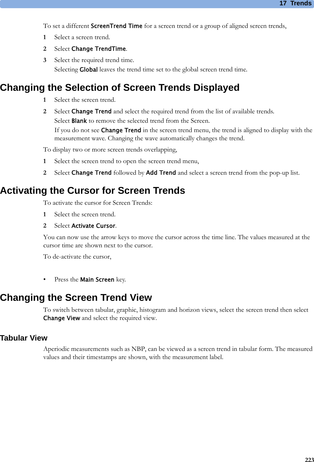
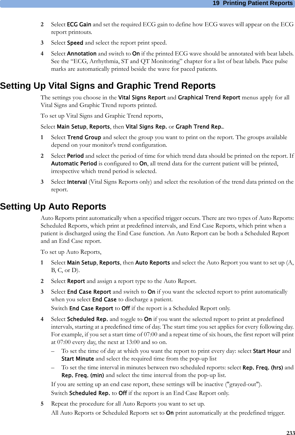
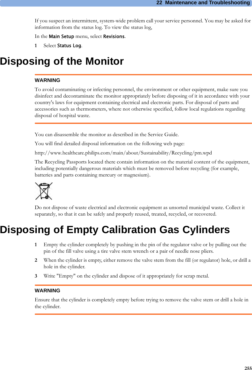
![6 Managing Patients and Equipment104ECG Source Tracking at the Information CenterThe Information Center continuously checks whether a valid ECG signal is coming from the monitor or from another assigned device. If you unplug the ECG patient cable from the monitor and plug it into another device, the Information Center will automatically switch to monitoring the ECG from the other device. At the monitor, its own ECG measurement will be deactivated and the Setup ECG menu will no longer be accessible.When you unplug the patient cable from the other device and plug it back into the monitor again, the Information Center will switch back to monitoring the ECG from the monitor. The ECG measurement will be activated again at the monitor. [Note that in this case, as the screen switches back to the monitor's own measurements, the SpO2T measurement (if present) will no longer be displayed].In the same way the source is tracked when a telemetry device is directly connected to a monitor, then disconnected and vice versa.In case of ambiguity, a yellow INOP message !!Check ECG Source indicates that more than one valid ECG source is active.Synchronized SettingsFor some measurements, settings can be synchronized between the monitor and another measurement device. For example, if ECG is measured at the monitor, and then the patient is connected to a telemetry device for monitoring, the Information Center will use the monitor settings for the telemetry device. In general, the following settings will be synchronized:Heart Rate HR/Pulse Alarm On/Off, Heart Rate High/Low Limit,ECG ECG On/Off, Primary Lead, Secondary Lead, Va Lead1, Vb Lead1, Lead PlacementArrhythmia Analysis Mode, Arrhythmia On/Off, Asystole Threshold, Pause Threshold, VTach HR, VTach Run, PVCs/min, Vent. Rhythm, SVT HR, SVT Run, PVCs/min On/Off, Pacer not capture On/Off, Pacer not pace On/Off, Non-Sustain On/Off, Vent. Rhythm On/Off, Run PVCs On/Off, Pair PVCs On/Off, Missed Beat On/Off, Pause On/Off, R-on-T PVCs On/Off, Vent. Bigeminy On/Off, Vent. Trigeminy On/Off, Multiform PVCs On/Off, Irregular HR On/Off, SVT On/Off, Afib On/Off, Afib/IrrHR Timeout, Afib/IrrHR End ThresholdST ST Analysis On/Off, ST Alarm On/Off, ISO Point, J point, ST point, ST Priority List, Single ST Alarm Limit, Multi ST Alarm Limit, ST-Index On/Off, ST Alarm Mode, ISO/J-Point Detection, ST Lead On/Off, ST BaselineQT QT analysis On/Off, QT Lead, QTc High Alarm On/Off, QTc Alarm On/Off, QTc High Limit, QTc High Limit, QTc Formula2, QT Baseline3SpO2TSpO2 Alarms on/off, SpO2 Alarm limits, SpO2 Low Alarm Delay, SpO2 High Alarm Limit, Desat Alarm LimitNBP Alarm Suppression On/Off, Pulse(SpO2) On/Off1Va and Vb leads are reset to default (V2, V5) if the configured Va or Vb lead for the telemetry device is not one of V1 through V6.2This setting will only be synchronized when the Information Center supports QT Analysis for Telemetry3With PIIC, QT baseline is synchronized, but not QT snippets.](https://usermanual.wiki/Philips-Medical-Systems-North-America/WLANBV2.User-Manual-IntelliVue-MP2/User-Guide-2137734-Page-104.png)
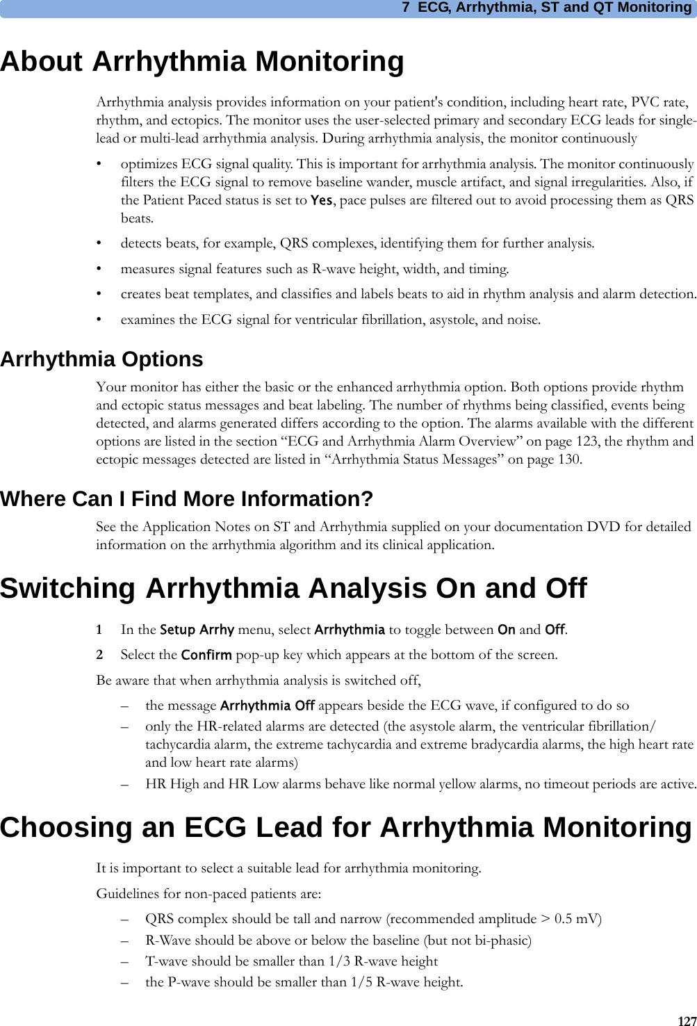
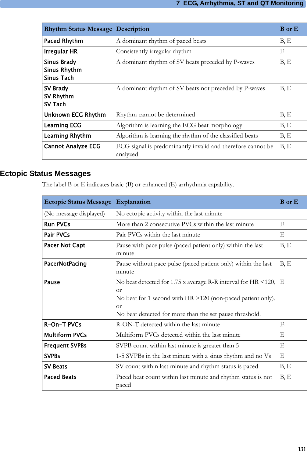


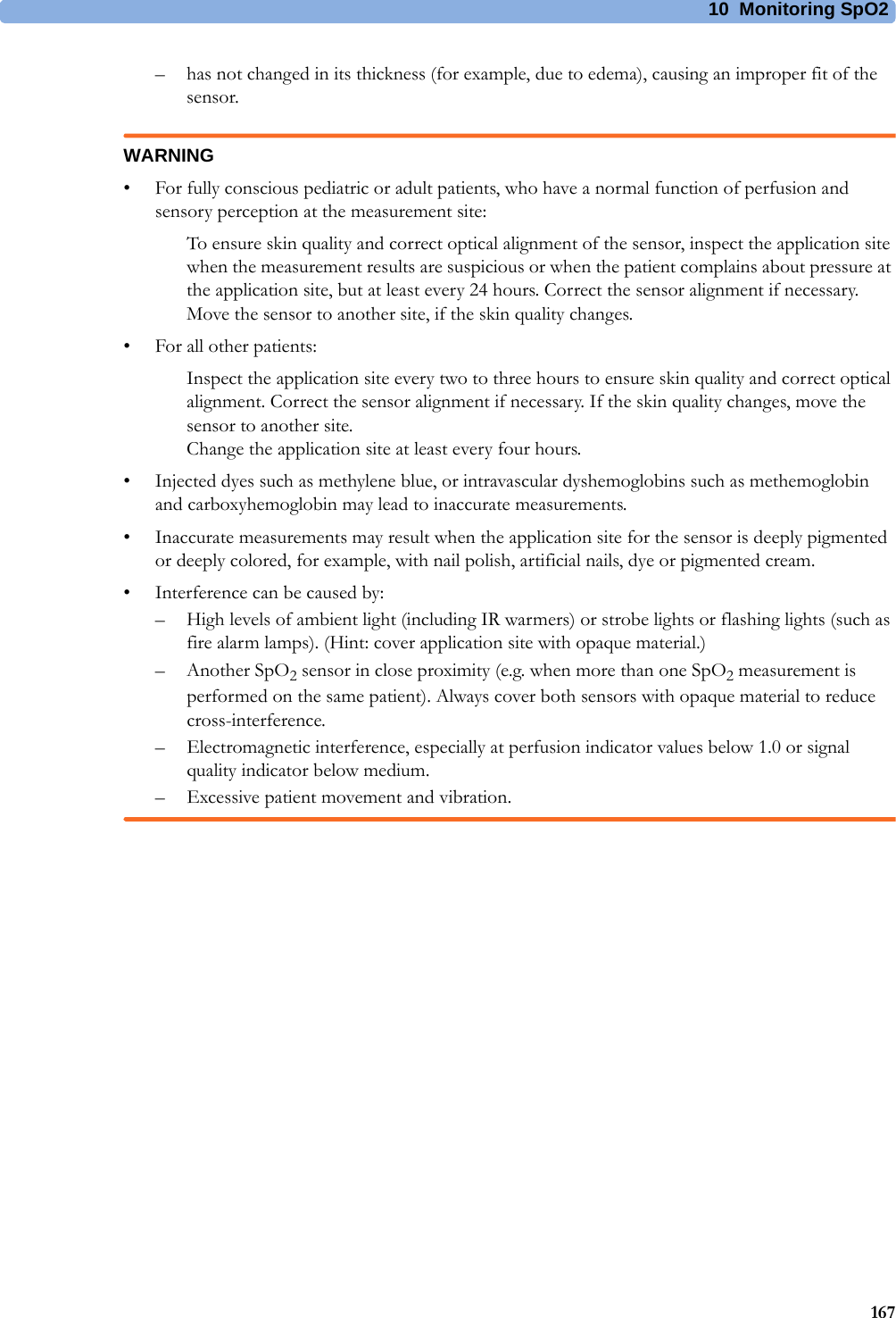
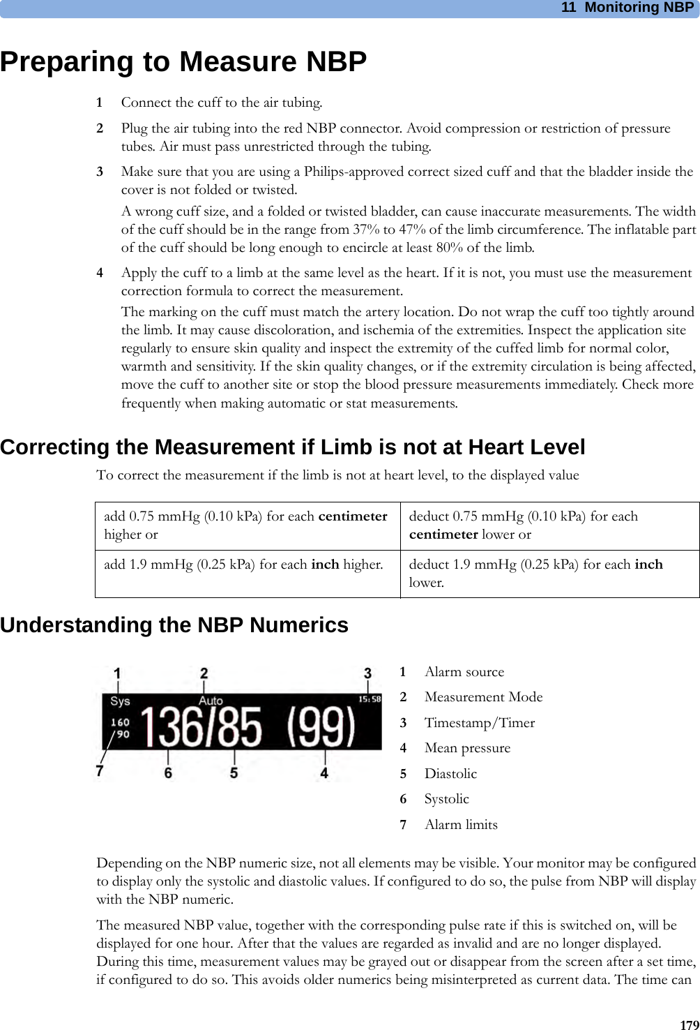
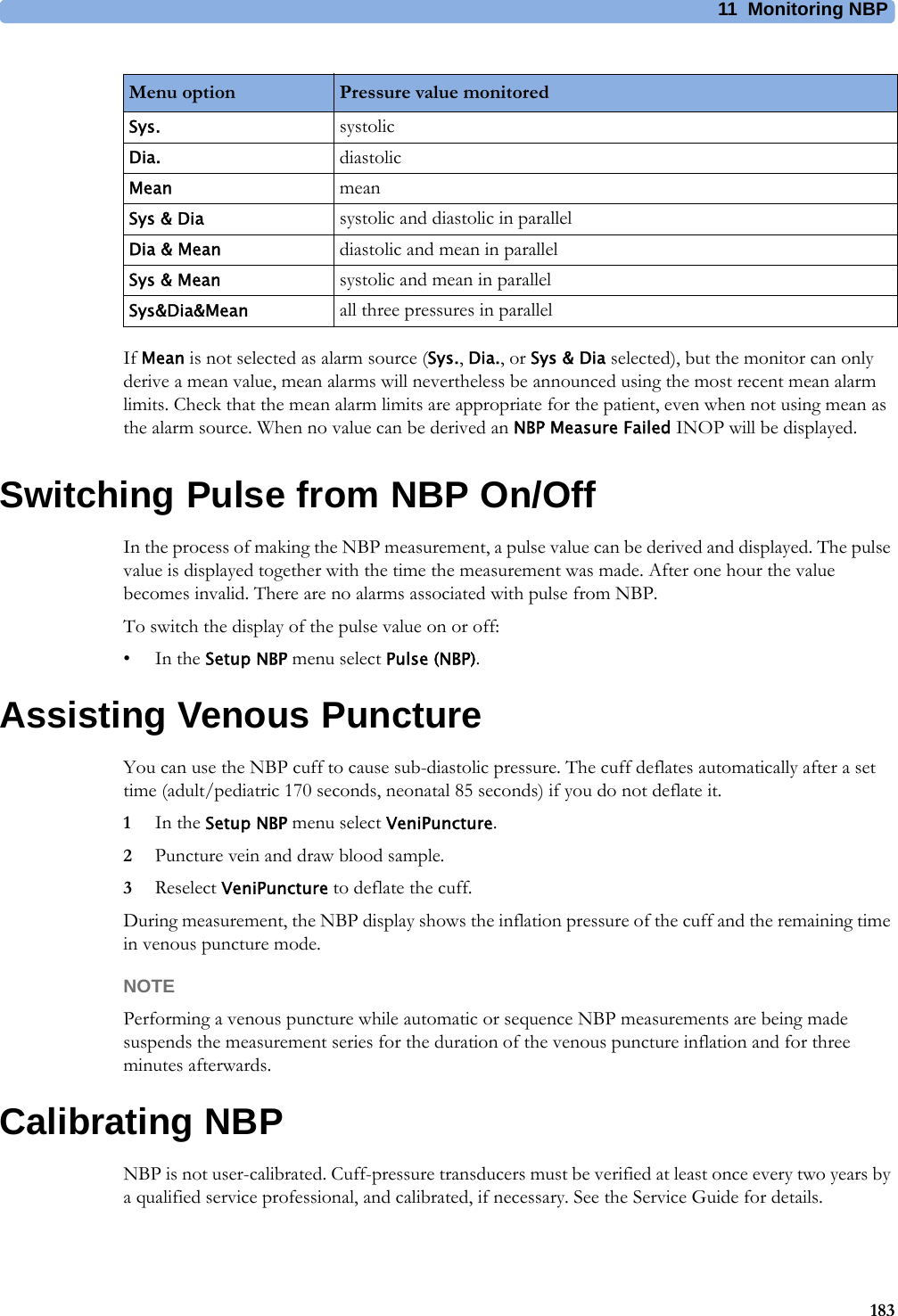


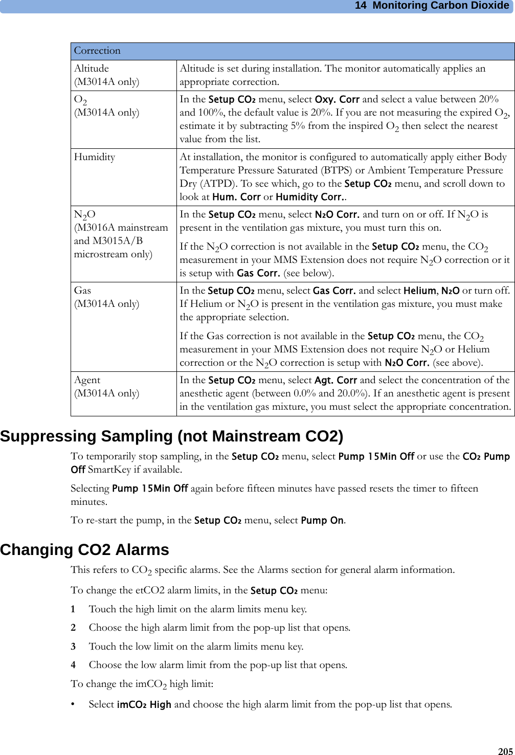


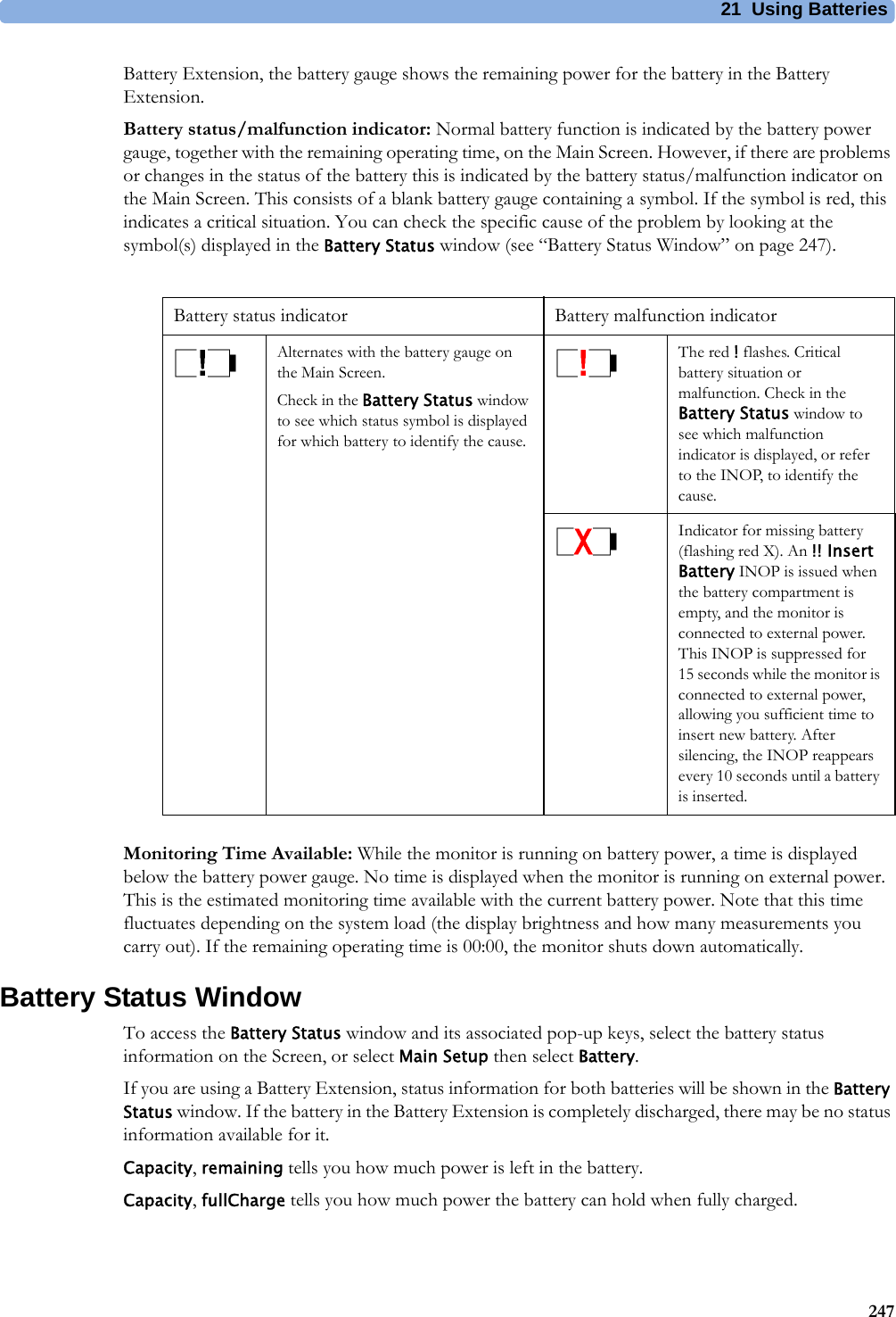

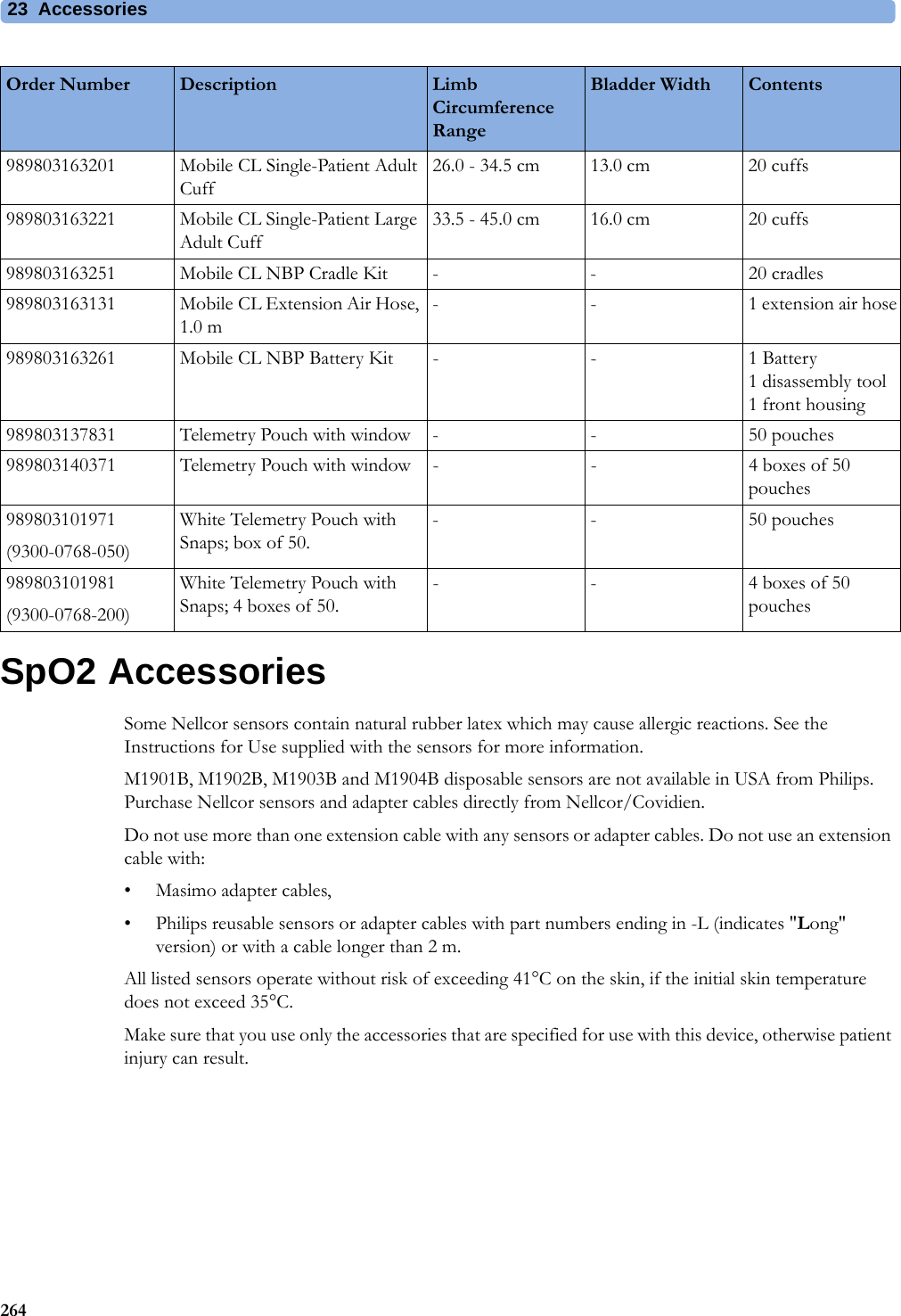

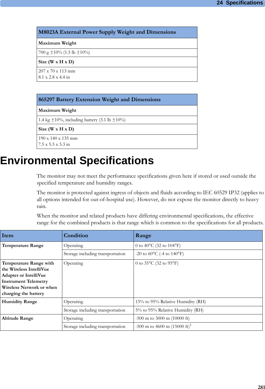
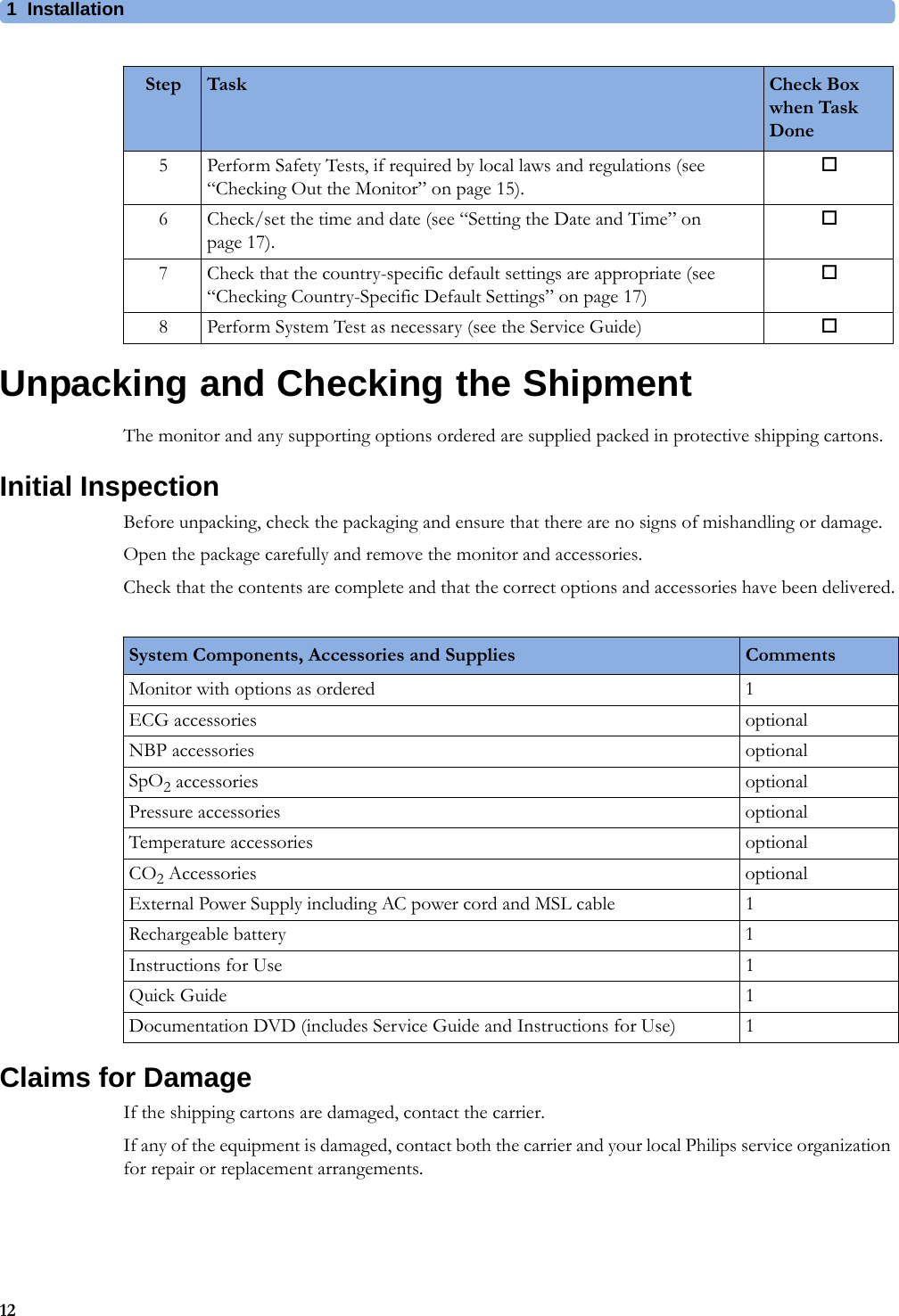
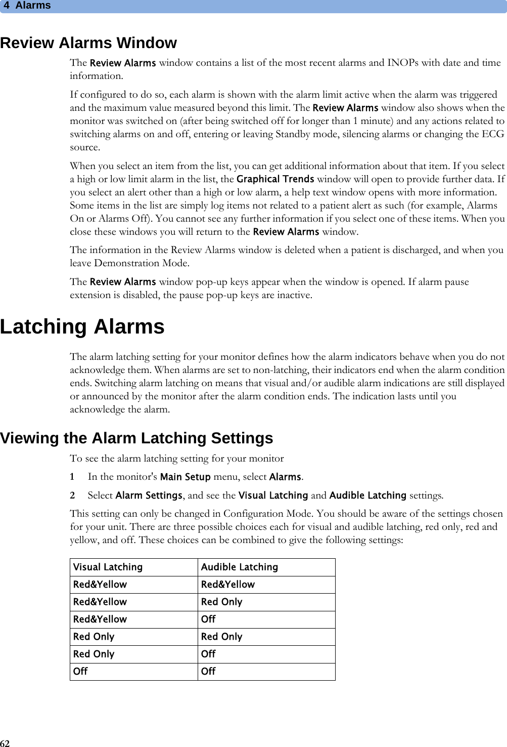
![24 Specifications289SVT Run 3 to 99 SV beats 1 SV beatST High -19.8 to +20 mm 0.2 mmST Low -20 to +19.8 mm 0.2 mmSTE Limit -20 to +20 mm 0.2 mmQTc High 200 ms to 800 ms 10 ms stepsQTc High 30 ms to 200 ms 10 ms stepsECG/Arrhythmia/ST/QT Alarm Specifications Range AdjustmentECG/Arrhythmia/ST Supplemental Information as required by AAMI EC11/13, IEC 60601-2-27Respiration Excitation Waveform Sinusoidal signal, 260 A, 40.5 kHzNoise Suppression RL drive gain 44 dB max., max. voltage 1.8 VrmsTime to Alarm for Tachycardia Vent Tachycardia1mVpp,206 bpmGain 0.5, Range 6.5 to 8.4 seconds, Average 7.2 secondsGain 1.0 Range 6.1 to 6.9 seconds, Average 6.5 secondsGain 2.0, Range 5.9 to 6.7 seconds, Average 6.3 secondsVent Tachycardia2mVpp,195 bpmGain 0.5, Range 5.4 to 6.2 seconds, Average 5.8 secondsGain 1.0, Range 5.7 to 6.5 seconds, Average 6.1 secondsGain 2.0, Range 5.3 to 6.1 seconds, Average 5.7 secondsTall T-Wave Rejection Capability Exceeds ANSI/AAMI EC 13 Sect. 3.1.2.1(c) minimum recommended 1.2 mV T-Wave amplitudeHeart Rate Averaging Method Three different methods are used:Normally, heart rate is computed by averaging the 12 most recent RR intervals.For runs of PVCs, up to 8 RR intervals are averaged to compute the HR.If each of 3 consecutive RR intervals is greater than 1200 ms (that is, rate less than 50 bpm), then the 4 most recent RR intervals are aver\-aged to compute the HR.Response Time of Heart Rate Meter to Change in Heart Rate HR change from 80 to 120 bpm:Range: [6.4 to 7.2 seconds] Average: 6.8 secondsHR change from 80 to 40 bpm:Range: [5.6 to 6.4 sec] Average: 6.0 secondsHeart Rate Meter Accuracy and Response to Irregular Rhythm Ventricular bigeminy: 80 bpmSlow alternating ventricular bigeminy: 60 bpmRapid alternating ventricular bigeminy: 120 bpmBidirectional systoles: 90 bpmAccuracy of Input Signal Reproduction Methods A and D were used to establish overall system error and frequency response.Pacemaker Pulse Rejection Performance Rejection of pacemaker pulses with amplitudes from ±2 mV to ±700 mV and widths from 0.1 ms to 2.0 ms (Method A)Pacemaker Pulse Rejection of fast ECG signals 2.2 V/s RTI (Paced Mode)Minimum input slew rate 2.2 V/s RTI](https://usermanual.wiki/Philips-Medical-Systems-North-America/WLANBV2.User-Manual-IntelliVue-MP2/User-Guide-2137734-Page-289.png)

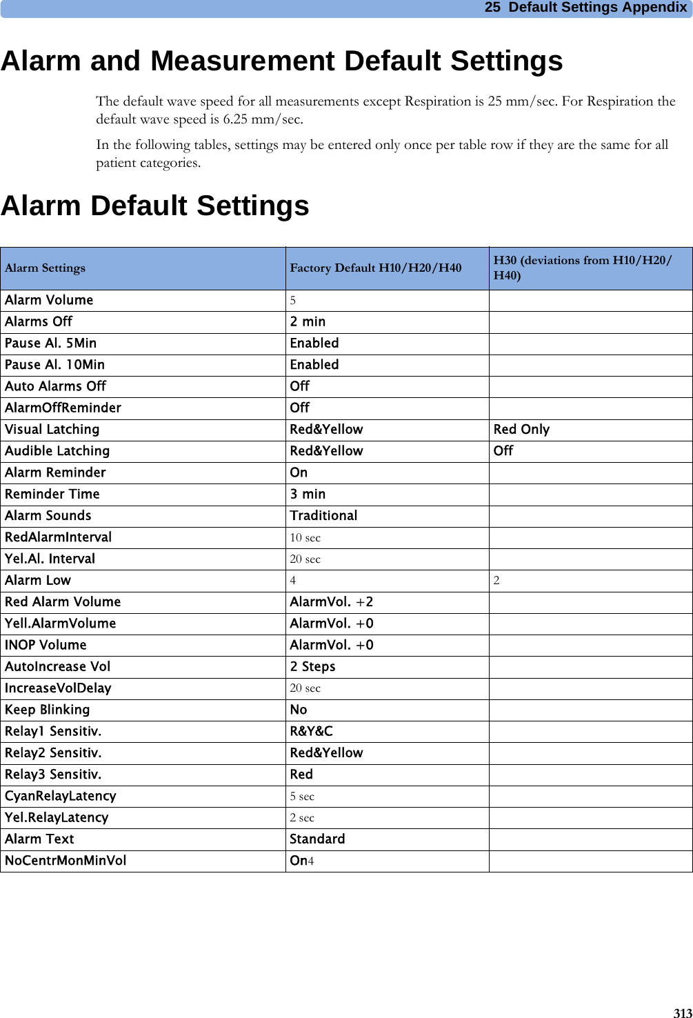
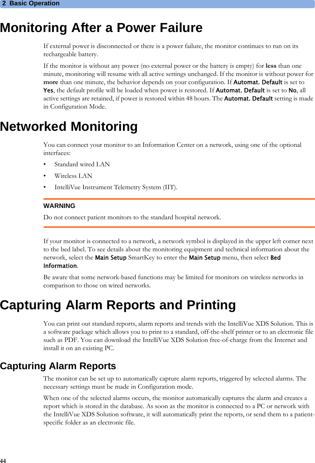
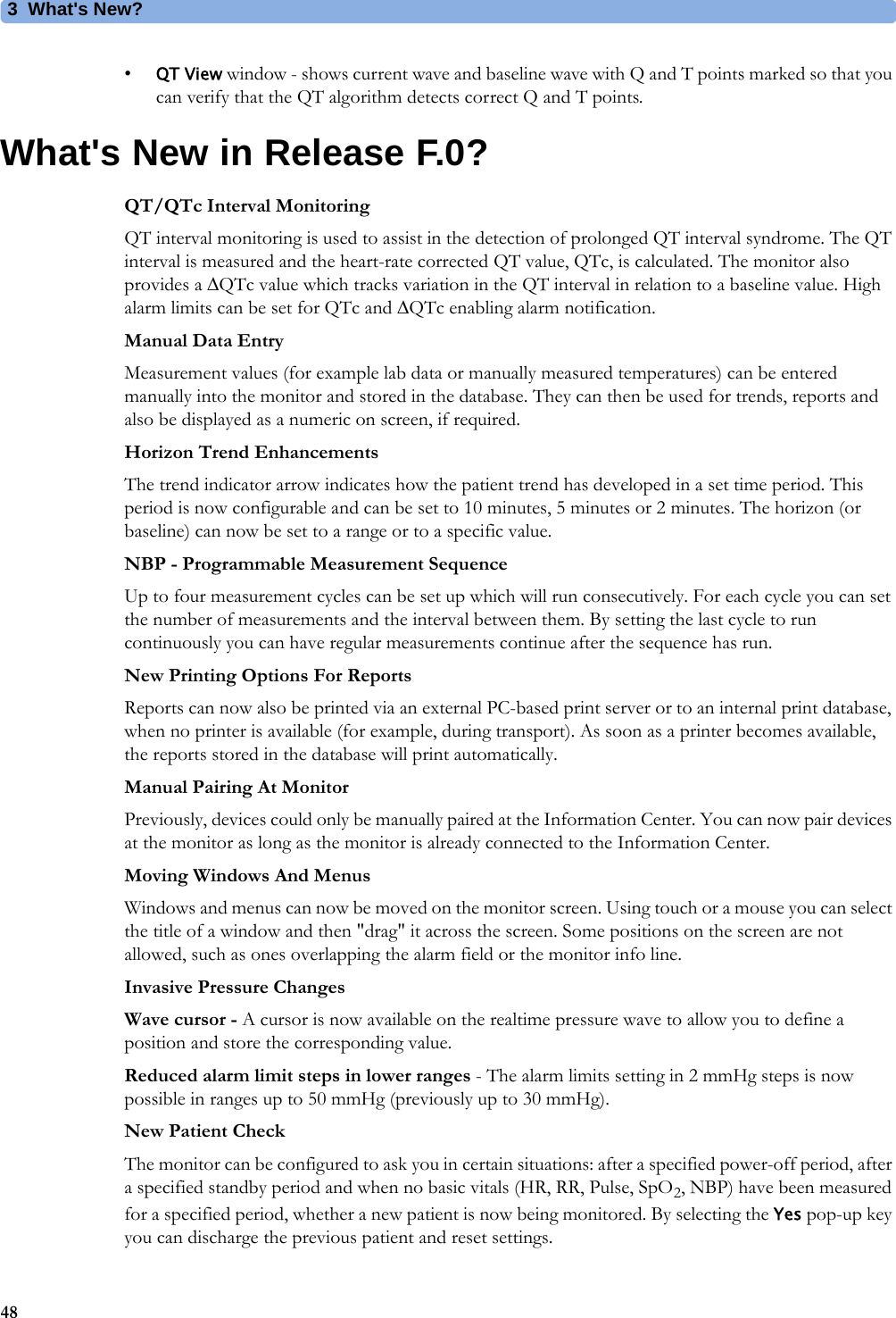
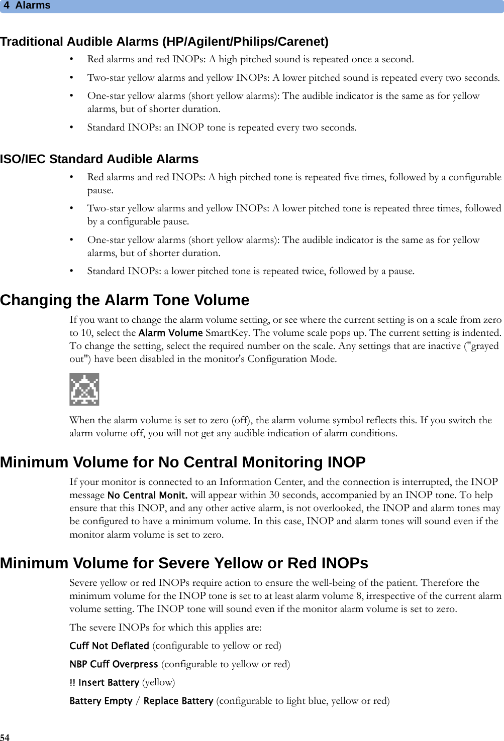
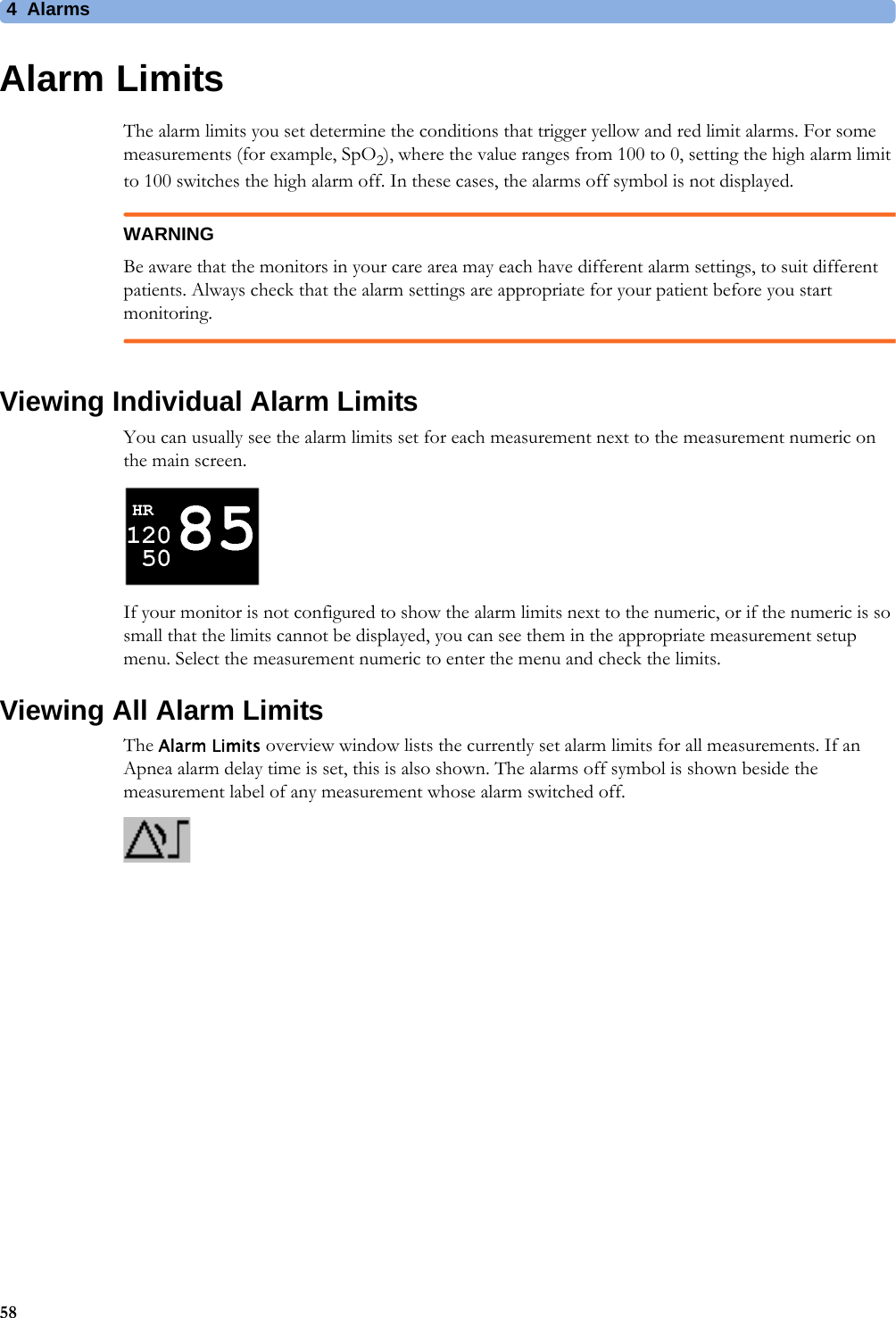
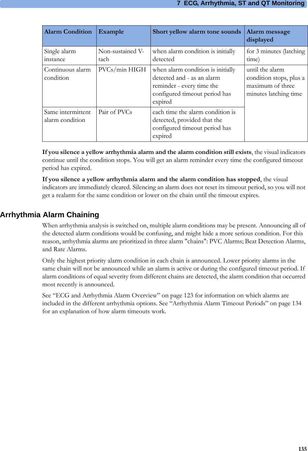
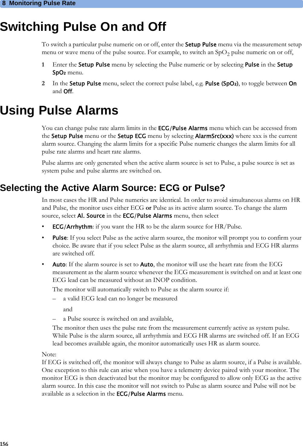
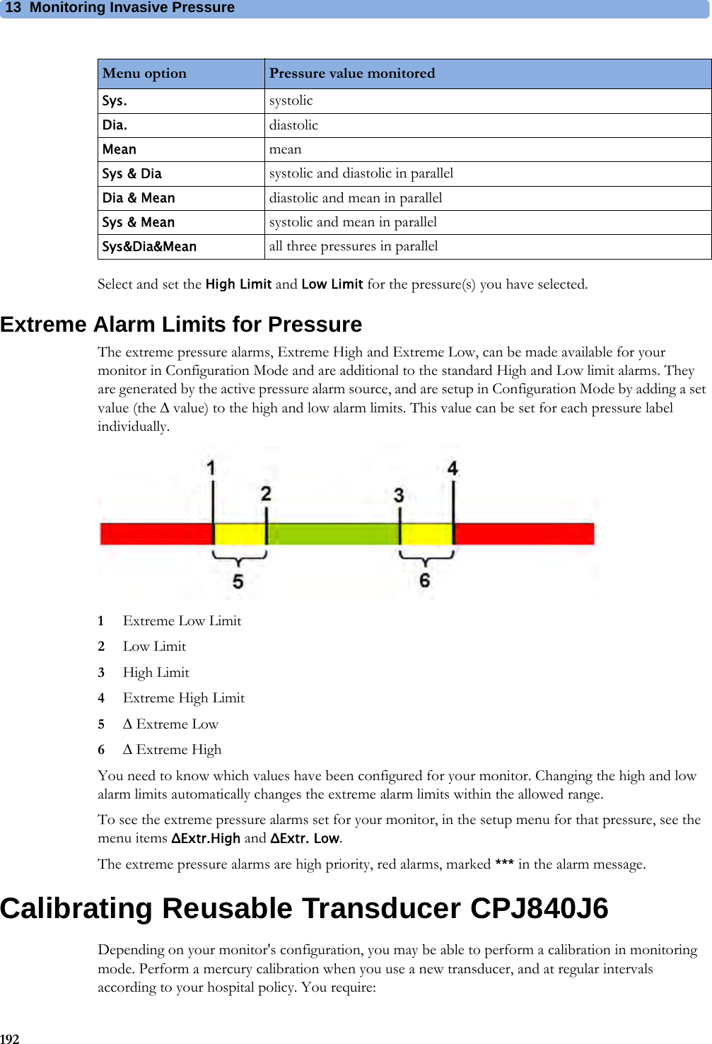
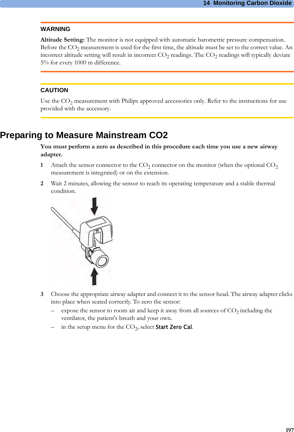
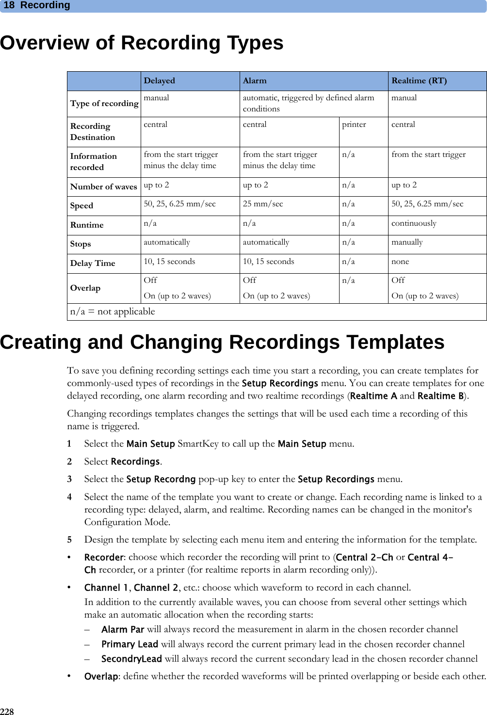
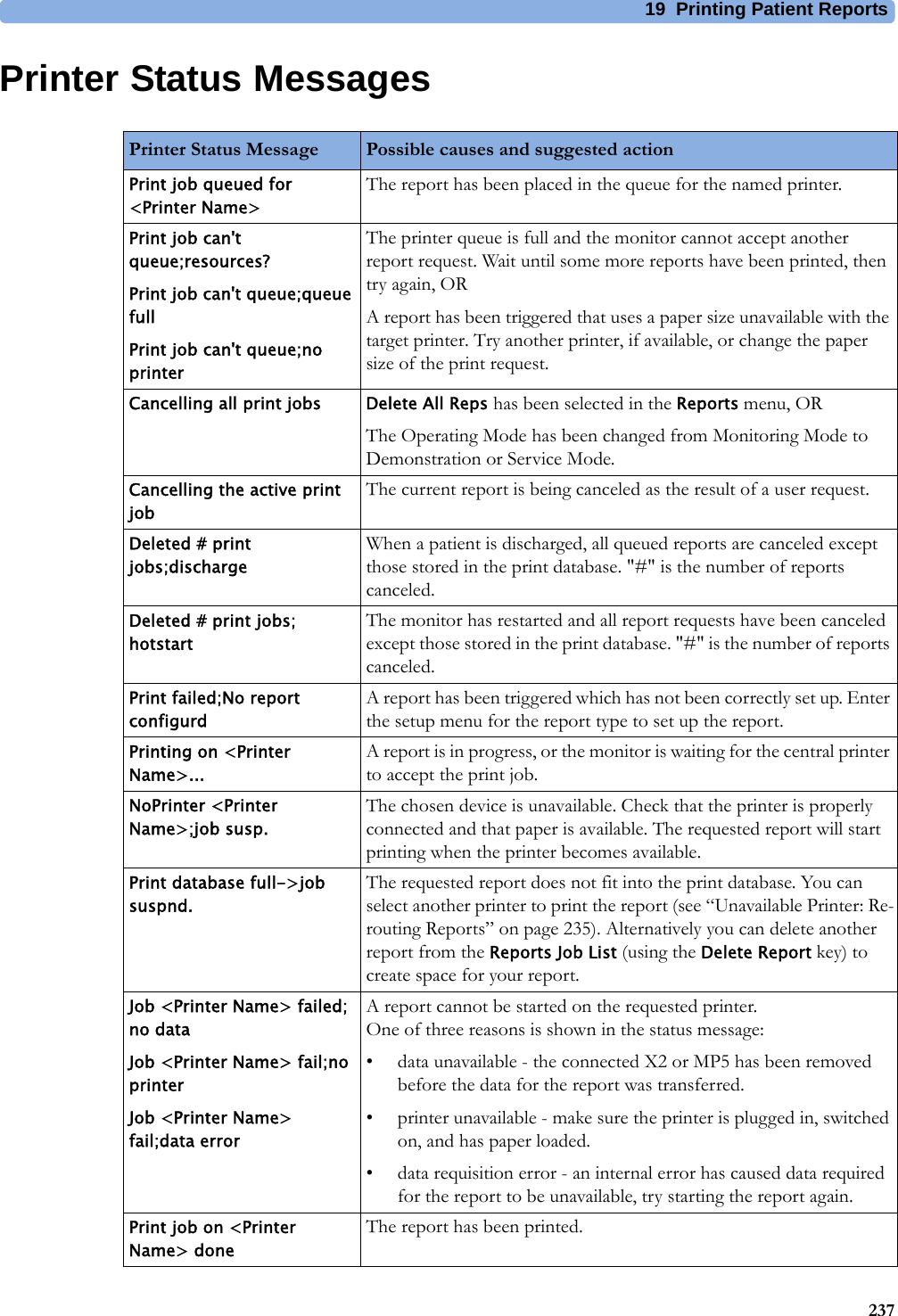
![2530525Default Settings AppendixThis appendix documents the most important default settings of your monitor as it is delivered from the factory. For a comprehensive list and explanation of default settings, see the Configuration Guide supplied with your monitor. The monitor's default settings can be permanently changed in Configuration Mode.Note: If your monitor has been ordered pre-configured to your requirements, the settings at delivery will be different from those listed here.Country-Specific Default SettingsCertain default settings are specific to a particular country. These are listed here for all countries alphabetically.Country-Description Line Frequency50/60 [Hz]UnitsWeightkg, lbUnitsHeightin, cmECG Cable ColorIEC, AAMIAfghanistan 50 kg cm AAMIÅland Islands 50 kg cm IECAlbania 50 kg cm IECAlgeria 50 kg cm IECAmerican Samoa 60 lb in AAMIAndorra 60 lb in AAMIAngola 50 kg cm IECAnguilla 60 lb in AAMIAntarctica 60 lb in AAMIAntigua and Barbuda 50 kg cm AAMIArgentina 50 kg cm AAMIArmenia 50 kg cm IECAruba 60 kg cm AAMIAustralia 50 kg cm AAMIAustria 50 kg cm IECAzerbaijan 50 kg cm IEC](https://usermanual.wiki/Philips-Medical-Systems-North-America/WLANBV2.User-Manual-IntelliVue-MP2/User-Guide-2137734-Page-305.png)
![25 Default Settings Appendix306Bahamas 60 kg cm AAMIBahrain 50 kg cm AAMIBangladesh 50 kg cm IECBarbados 50 kg cm AAMIBelarus 50 kg cm IECBelgium 50 kg cm IECBelize 60 lb in AAMIBenin 60 lb in AAMIBermuda 60 kg cm AAMIBhutan 60 lb in AAMIBolivia 60 kg cm AAMIBosnia and Herzegovina 50 kg cm IECBotswana 50 kg cm IECBouvet Island 60 lb in AAMIBrazil 60 kg cm AAMIBritish Indian Ocean Territory 60 lb in AAMIBrunei Darussalam 50 kg cm IECBulgaria 50 kg cm IECBurkina Faso 50 kg cm IECBurundi 50 kg cm IECCambodia 50 kg cm IECCameroon 50 kg cm IECCanada 60 kg cm AAMICape Verde 60 lb in AAMICayman Islands 60 kg cm AAMICentral African Republic 50 kg cm IECChad 60 lb in AAMIChile 50 kg cm AAMIChina 50 kg cm AAMIChristmas Islands 60 lb in AAMICocos Keeling Islands 60 lb in AAMIColombia 60 kg cm AAMIComoros 60 lb in AAMICongo 50 kg cm IECCongo, The Democratic Republic of the50 kg cm IECCountry-Description Line Frequency50/60 [Hz]UnitsWeightkg, lbUnitsHeightin, cmECG Cable ColorIEC, AAMI](https://usermanual.wiki/Philips-Medical-Systems-North-America/WLANBV2.User-Manual-IntelliVue-MP2/User-Guide-2137734-Page-306.png)
![25 Default Settings Appendix307Cook Islands 60 lb in AAMICosta Rica 60 kg cm AAMICôte d'Ivoire 50 kg cm IECCroatia 50 kg cm IECCuba 60 kg cm IECCyprus 50 kg cm IECCzech Republic 50 kg cm IECDenmark 50 kg cm IECDjibouti 50 kg cm IECDominica 50 kg cm AAMIDominican Republic 60 kg cm AAMIEcuador 60 kg cm AAMIEgypt 50 kg cm IECEl Salvador 60 kg cm AAMIEquatorial Guinea 50 kg cm IECEritrea 50 kg cm IECEstonia 50 kg cm IECEthiopia 50 kg cm IECFalkland Islands, Malvinas 60 lb in AAMIFaroe Islands 60 lb in AAMIFiji 60 lb in AAMIFinland 50 kg cm IECFrance 50 kg cm IECFrench Guiana 50 kg cm IECFrench Polynesia 60 lb in AAMIFrench Southern Territories 60 lb in AAMIGabon 50 kg cm IECGambia 50 kg cm IECGeorgia 60 lb in AAMIGermany 50 kg cm IECGhana 50 kg cm IECGibraltar 60 lb in AAMIGreece 50 kg cm IECGreenland 60 lb in AAMIGrenada 50 kg cm AAMIGuadeloupe 50 kg cm IECCountry-Description Line Frequency50/60 [Hz]UnitsWeightkg, lbUnitsHeightin, cmECG Cable ColorIEC, AAMI](https://usermanual.wiki/Philips-Medical-Systems-North-America/WLANBV2.User-Manual-IntelliVue-MP2/User-Guide-2137734-Page-307.png)
![25 Default Settings Appendix308Guam 60 lb in AAMIGuatemala 60 kg cm AAMIGuernsey 50 kg cm IECGuinea 60 lb in AAMIGuinea-Bissau 60 lb in AAMIGuyana 60 kg cm AAMIHaiti 60 kg cm AAMIHeard Island and McDonald Islands60 lb in AAMIHoly See, Vatican City State 60 lb in AAMIHonduras 60 kg cm AAMIHong Kong 50 kg cm IECHungary 50 kg cm IECIceland 50 kg cm IECIndia 50 kg cm IECIndonesia 50 kg cm IECIran, Islamic Republic of 50 kg cm AAMIIraq 50 kg cm AAMIIreland 50 kg cm IECIsle of Man 50 kg cm IECIsrael 50 kg cm IECItaly 50 kg cm IECJamaica 50 kg cm AAMIJapan 50 kg cm IECJersey 50 kg cm IECJordan 50 kg cm AAMIKazakhstan 50 kg cm IECKenya 50 kg cm IECKiribati 60 lb in AAMIKorea, Democratic People's Republic of60 lb in AAMIKorea, Republic of 60 kg cm AAMIKuwait 50 kg cm AAMIKyrgyzstan 60 lb in AAMILao People's Democratic Republic50 kg cm IECLatvia 50 kg cm IECCountry-Description Line Frequency50/60 [Hz]UnitsWeightkg, lbUnitsHeightin, cmECG Cable ColorIEC, AAMI](https://usermanual.wiki/Philips-Medical-Systems-North-America/WLANBV2.User-Manual-IntelliVue-MP2/User-Guide-2137734-Page-308.png)
![25 Default Settings Appendix309Lebanon 50 kg cm AAMILesotho 50 kg cm IECLiberia 50 kg cm IECLibyan Arab Jamahiriya 60 lb in AAMILiechtenstein 60 lb in AAMILithuania 50 kg cm IECLuxembourg 50 kg cm IECMacao 50 kg cm IECMacedonia, The former Yugoslavian Republic of50 kg cm IECMadagascar 50 kg cm IECMalawi 50 kg cm IECMalaysia 50 kg cm IECMaldives 60 lb in AAMIMali 50 kg cm IECMalta 50 kg cm IECMarshall Islands 60 lb in AAMIMartinique 60 kg cm IECMauritania 50 kg cm IECMauritius 60 lb in AAMIMayotte 60 lb in AAMIMexico 60 kg cm AAMIMicronesia, Federal States of 60 lb in AAMIMoldova, Republic of 60 lb in AAMIMonaco 60 lb in AAMIMongolia 60 lb in AAMIMontenegro 50 kg cm IECMontserrat 50 kg cm AAMIMorocco 50 kg cm IECMozambique 50 kg cm IECMyanmar 60 lb in AAMINamibia 50 kg cm IECNauru 60 lb in AAMINepal 50 kg cm IECNetherlands 50 kg cm IECNetherlands Antilles 50 kg cm AAMICountry-Description Line Frequency50/60 [Hz]UnitsWeightkg, lbUnitsHeightin, cmECG Cable ColorIEC, AAMI](https://usermanual.wiki/Philips-Medical-Systems-North-America/WLANBV2.User-Manual-IntelliVue-MP2/User-Guide-2137734-Page-309.png)
![25 Default Settings Appendix310New Caledonia 60 lb in AAMINew Zealand 50 kg cm AAMINicaragua 60 kg in AAMINiger 50 kg cm IECNigeria 50 kg cm IECNiue 60 lb in AAMINorfolk Islands 60 lb in AAMINorthern Mariana Islands 60 lb in AAMINorway 50 kg cm IECOman 50 kg cm AAMIPakistan 50 kg cm IECPalau 60 lb in AAMIPalestinian Territory 50 kg cm AAMIPanama 60 lb in AAMIPapua New Guinea 60 lb in AAMIParaguay 50 kg cm AAMIPeru 60 kg cm AAMIPhilippines 60 kg cm AAMIPitcairn 60 lb in AAMIPoland 50 kg cm IECPortugal 50 kg cm IECPuerto Rico 60 lb in AAMIQatar 50 kg cm AAMIReunion 60 lb in AAMIRomania 50 kg cm IECRussian Federation 50 kg cm IECRwanda 50 kg cm IECSaint Helena 60 lb in AAMISaint Kitts and Nevis 60 kg cm AAMISaint Lucia 50 kg cm AAMISaint Pierre and Miquelon 60 lb in AAMISaint Vincent & the Grenadines 50 kg cm AAMISamoa 60 lb in AAMISan Marino 60 lb in AAMISao Tome and Principe 60 lb in AAMISaudi Arabia 50 kg cm AAMICountry-Description Line Frequency50/60 [Hz]UnitsWeightkg, lbUnitsHeightin, cmECG Cable ColorIEC, AAMI](https://usermanual.wiki/Philips-Medical-Systems-North-America/WLANBV2.User-Manual-IntelliVue-MP2/User-Guide-2137734-Page-310.png)
![25 Default Settings Appendix311Senegal 50 kg cm IECSerbia 50 kg cm IECSerbia & Montenegro 50 kg cm IECSeychelles 60 lb in AAMISierra Leone 50 kg cm IECSingapore 50 kg cm IECSlovakia 50 kg cm IECSlovenia 50 kg cm IECSolomon Islands 60 lb in AAMISomalia 50 kg cm IECSouth Africa 60 lb in AAMISouth Georgia and the South Sandwich Islands60 lb in AAMISpain 50 kg cm IECSri Lanka 50 kg cm IECSudan 50 kg cm IECSuriname 60 kg cm AAMISvalbard and Jan Mayen 60 lb in AAMISwaziland 60 lb in AAMISweden 50 kg cm IECSwitzerland 50 kg cm IECSyrian Arab Rep 50 kg cm AAMITaiwan, Province of China 60 kg cm AAMITajikistan 60 lb in AAMITanzania, United Republic of 60 lb in AAMIThailand 50 kg cm AAMITimor-Leste 60 lb in AAMITogo 60 lb in AAMITokelau 60 lb in AAMITonga 60 lb in AAMITrinidad and Tobago 60 kg cm AAMITunisia 50 kg cm IECTurkey 50 kg cm IECTurkmenistan 60 lb in AAMITurks and Caicos Islands 60 kg cm AAMITuvalu 60 lb in AAMICountry-Description Line Frequency50/60 [Hz]UnitsWeightkg, lbUnitsHeightin, cmECG Cable ColorIEC, AAMI](https://usermanual.wiki/Philips-Medical-Systems-North-America/WLANBV2.User-Manual-IntelliVue-MP2/User-Guide-2137734-Page-311.png)
![25 Default Settings Appendix312Uganda 60 lb in AAMIUkraine 60 lb in AAMIUnited Arab Emirates 50 kg cm AAMIUnited Kingdom 50 kg cm IECUnited States 60 lb in AAMIUnited States Minor Outlying Islands60 lb in AAMIUruguay 50 kg cm AAMIUzbekistan 60 lb in AAMIVanuatu 60 lb in AAMIVenezuela 60 lb in AAMIViet Nam 50 kg cm IECVirgin Islands, British 50 kg cm AAMIVirgin Islands, United States 60 lb in AAMIWallis and Futuna Islands 60 lb in AAMIWestern Sahara 50 kg cm IECYemen 50 kg cm AAMIZambia 60 lb in AAMIZimbabwe 60 lb in AAMICountry-Description Line Frequency50/60 [Hz]UnitsWeightkg, lbUnitsHeightin, cmECG Cable ColorIEC, AAMI](https://usermanual.wiki/Philips-Medical-Systems-North-America/WLANBV2.User-Manual-IntelliVue-MP2/User-Guide-2137734-Page-312.png)