Phonex Broand ReadyNet SG5 10/100/1000Mbps Fast Ethernet Switch User Manual
Phonex Broadband Corporation 10/100/1000Mbps Fast Ethernet Switch
User manual
Quick Installation Guide
SG5 5 Port Gigabit
Ethernet Switch
•HubtoSwitch–Ahubcanbeconnectedviaatwo-pairCategory3,
4,or5UTP/STPStraight-ThroughorCrossovercable.For1000Mbps
operationaCategory5cablemustbeused.Theconnectionis
accomplishedfromanyportofthehubtoanyportoftheSG5.
•SG5toOtherDevices–TheSG5canbeconnectedtoanotherswitch
orotherdevices(routers,bridges,etc.)viaatwo-pairCategory3,4,5
UTP/STPStraight-ThroughorCrossovercable.ACategory5cable
mustbeusedfor1000Mbpsoperation.Theconnectioncanbe
accomplishedfromanyportontheSG5toanyofthe10Mbps,
100Mbpsor1000Mbpsportsonanotherswitchorotherdevices.
•PortSpeed&DuplexMode–Afterpluggingtheselectedcableto
aspecicport,thesystemusesauto-negotiationtodeterminethe
transmissionmode,auto-detectingthenetworkspeedforanynew
twisted-pairconnection.
Iftheattacheddevicedoesnotsupportauto-negotiationorhasauto-
negotiationdisabled,anauto-sensingprocessisinitiatedtoselectthe
speedandhalf-duplexmodeisselected.
The SG5 is very easy to set up; no network management is
required. Just power it up and connect the cables. Keep in mind the
length of an Ethernet cable from one device to another
cannot exceed 100 meters.
Auto MDI/MDI-X Ports
AllportssupportautomaticMDI/MDI-Xcrossoverdetection.TheAuto
MDI/MDI-Xfunctionmakesitsimpletoconnecttotheswitch–justplug
eitheraCrossoverorStraight-ThroughCAT5cableintoanyport.
LED Indicators
Cable Quality
ForconnectionstotheSG5,usetheserulestodeterminewhich
cabletouse.
•Forconnectionsto10BASE-Tand100BASE-TXdevicesuseCategory
5or5eUTP/STPcable.
•Forconnectionsto1000BASE-Tand100BASE-TXdevicesuse
Category5eorUTP/STPcable.All1000BASE-Tconnectionsoperate
infullduplexmode.
•PCtoSwitch–Acomputercanbeconnectedviaatwo-pairCategory
3,4,5UTP/STPStraight-ThroughorCrossovercabletoanyoftheve
ports.LEDindicatorsforthePCconnectiondependonthecapability
ofthecomputer’sEthernetcard.IftheLEDindicatorsarenotlitafter
makingaproperconnection,checkthecomputer’sEthernetcard,the
cable,andtheSG5’sconditionsandconnections.
Continued
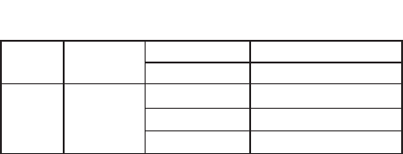
LED Panel
signature Status Description
Power
Indicator Power
GreenON SwitchispoweredON
OFF SwitchispoweredOFF
Status
Indicator
1,2,3,4,
and5
GreenON Link
GreenBlinking Activity
OFF Nolinkpath

FCC Information and Copyright
This equipment has been tested and found to comply with the limits for a Class B digital device,
pursuant to part 15 of the FCC Rules.
These limits are designed to provide reasonable protection against harmful interference in a residential
installation. This equipment generates,
uses and can radiate radio frequency energy and, if not installed and used in accordance with the
instructions, may cause harmful interference
to radio communications. However, there is no guarantee that interference will not occur in a particular
installation. If this equipment does
cause harmful interference to radio or television reception, which can be determined by turning the
equipment off and on, the user is
encouraged to try to correct the interference by one or more of the following measures:
—Reorient or relocate the receiving antenna.
—Increase the separation between the equipment and receiver.
—Connect the equipment into an outlet on a circuit different from that to which the receiver is
connected.
—Consult the dealer or an experienced radio/TV technician for help.
15.19 Labelling requirements.
This device complies with part 15 of the FCC Rules. Operation is subject to the
following two conditions:
(1)This device may not cause harmful interference, and
(2) this device must accept any interference received, including interference that may
cause undesired operation.
changes or modifications not expressly approved by the party responsible for compliance could
void the user's authority to operate the equipment.