Phychips PRM92K20CE UHF RFID MODULE User Manual
Phychips Inc. UHF RFID MODULE
UserManual.wiki
>
Phychips
>
PRM92K20CE User Manual
User Manual
Navigation menu
Upload a User Manual
Namespaces
Wiki Guide
HTML
PDF
Info
Views
User Manual
Discussion / Help
Navigation
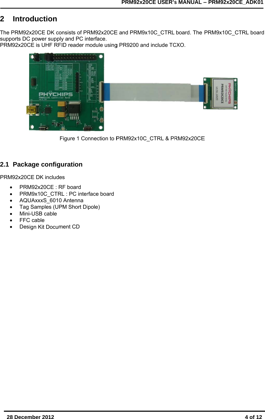
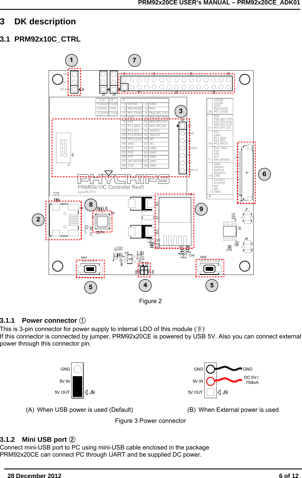
![28 December 2012 7 of 12 PRM92x20CE USER’s MANUAL – PRM92x20CE_ADK01 3.1.3 SWD port ③ In order to debug or firmware download, this SWD port is connected to H/W debugger such as ULINK2 and X-LINK (A) X-LINK port (B) ULINK2 port Figure 4 SWD port [Notice] SWD port power (3.3V) is provided by ULINK2 or X-LINK adapter. Please check jumper setting of adapter (refer to ULINK2 user’s guide, http://www.keil.com/support/man/docs/ulink2/ulink2_hw_jumpers.htm) 3.1.4 LED part ④ PRM9x10C_CTRL has two LED. One indicate POWER, the other indicate ACTIVE. When DC power is normally supplied, “POWER” LED is ON. When RFID reader is ready, “ACTIVE” LED is ON. “ACTIVE” LED is connected to GPIO(P07) of PRM92x20CE and change that function in Firmware Figure 5 PRM92x20CE_CTRL LED 3.1.5 RESETb button ⑤ This button is used when user want to reset PRM92x20CE and CP2102. (C) USB Reset (D) Module Reset Figure 6 Reset button 3.1.6 FFC connector ⑥ 30pin FFC connector has used for interconnection with PRM92x20CE](https://usermanual.wiki/Phychips/PRM92K20CE/User-Guide-1878138-Page-7.png)
![28 December 2012 11 of 12 PRM92x20CE USER’s MANUAL – PRM92x20CE_ADK01 [Appendix1] Channel Number Table 1. US band Channel Channel Frequency Channel Channel Frequency 1 917.10 MHz 26 922.10 MHz 2 917.30 MHz 27 922.30 MHz 3 917.50 MHz 28 922.50 MHz 4 917.70 MHz 29 922.70 MHz 5 917.90 MHz 30 922.90 MHz 6 918.10 MHz 31 923.10 MHz 7 918.30 MHz 32 923.30 MHz 8 918.50 MHz 33 923.50 MHz 9 918.70 MHz 34 923.70 MHz 10 918.90 MHz 35 923.90 MHz 11 919.10 MHz 36 924.10 MHz 12 919.30 MHz 37 924.30 MHz 13 919.50 MHz 38 924.50 MHz 14 919.70 MHz 39 924.70 MHz 15 919.90 MHz 40 924.90 MHz 16 920.10 MHz 41 925.10 MHz 17 920.30 MHz 42 925.30 MHz 18 920.50 MHz 43 925.50 MHz 19 920.70 MHz 44 925.70 MHz 20 920.90 MHz 45 925.90 MHz 21 921.10 MHz 46 926.10 MHz 22 921.30 MHz 47 926.30 MHz 23 921.50 MHz 48 926.50 MHz 24 921.70 MHz 49 926.70 MHz 25 921.90 MHz 50 926.90 MHz](https://usermanual.wiki/Phychips/PRM92K20CE/User-Guide-1878138-Page-11.png)
![28 December 2012 12 of 12 PRM92x20CE USER’s MANUAL – PRM92x20CE_ADK01 [Appendix2] FCC Certification Requirements 1. Caution Any changed or modifications not expressly approved by the party responsible for compliance could void the user`s authority to operate this equipment. 2. OEM installation guide I. OEM integrators must be instructed to ensure that the end-user has no manual instructions to remove or install the module. II. This module is to be installed only in mobile of fixed devices. ▪ Mobile device: The devices is to be generally used in such a way that a separation distance of at least 20cm is normally maintained between the transmitter`s radiating structures and the body of the user or nearby persons. ▪ Fixed devices: The device is physically secured at one location and is not able to be easily moved to another location. III. To ensure compliance with all non-transmitter functions the host manufacturer is responsible for ensuring compliance with the module(s) installed and fully operational. IV. To satisfy FCC exterior labeling requirements, the following text must be placed on exterior of the end product. V. An additional permanent label referring to the enclosed module: “Contains Transmitter Module FCC ID: XYZMODEL1” or “Contains FCC ID: XYZMODEL1” must be used. The host OEM user manual must also contain clear instructions on how end users can find and/or access the module and the FCC ID. 3. FCC RF exposure requirements The antenna used with this module must be installed to provide a separation distance of at least 20cm from all persons, and must not transmit simultaneously with any other antenna or transmitter except in accordance with FCC multi-transmitter product procedures. 4. FCC authorization for this module If this module is installed in portable devices or the different antenna configurations are used, the FCC authorizations are no longer considered valid and FCCID for module cannot be used on the final product. And the OEM installer will be responsible for re-evaluating the final product including this module and obtaining separate FCC authorization. 5. Information for importation of radio frequency devices in to the United States To ensure compliance with all non-transmitter functions the host manufacturer is responsible for ensuring compliance with the module(s) installed and fully operational. For example, if a host was previously authorized as an unintentional radiator under the Declaration of Conformity procedure without a transmitter certified module and a module is added, the host manufacturer is responsible for ensuring that the after the module is installed and operational the host continues to be compliant with the Part 15B unintentional radiator requirements. Please see CFR47 Part 2 Subpart J Equipment Authorization Procedures, KDB784748 D01 v07, and KDB 997198. 6. User Information This device complies with Part 15 of the FCC`s Rule. Operation is subject to the following to conditions; 1. This device may not cause harmful interference, and 2. This device must accept any interference received, including interference that may cause undesirable operation. This equipment has been tested and found to comply with the limits for a Class B digital device, pursuant to part 15 of the FCC Rules. These limits are designed to provide reasonable protection against harmful interference in a residential installation. This equipment generates, uses and can radiate radio frequency energy and, if not installed and used in accordance with the instructions, may cause harmful interference to radio communications. However, there is no guarantee that interference will not occur in a particular installation. If this equipment does cause harmful interference to radio or television reception, which can be determined by turning the equipment off and on, the user is encouraged to try to correct the interference by one or more of the following measures: - Reorient or relocate the receiving antenna. - Increase the separation between the equipment and receiver. - Connect the equipment into an outlet on a circuit different from that to which the receiver is connected. - Consult the dealer or an experienced radio/ TV technician for help.](https://usermanual.wiki/Phychips/PRM92K20CE/User-Guide-1878138-Page-12.png)