User Manual
PRM92K20CE
UHF RFID Module
User’s Manual

28 December 2012 2 of 12
PRM92x20CE USER’s MANUAL – PRM92x20CE_ADK01
Contents
1 Revision History ................................................................................................................................ 3
2 Introduction ....................................................................................................................................... 4
2.1 Package configuration ......................................................................................................................... 4
2.2 Features .............................................................................................................................................. 5
3 DK description ................................................................................................................................... 6
3.1 PRM92x10C_CTRL ............................................................................................................................. 6
4 Specifications .................................................................................................................................... 9
5 Address Information ....................................................................................................................... 10

28 December 2012 3 of 12
PRM92x20CE USER’s MANUAL – PRM92x20CE_ADK01
1 Revision History
Version Date Description
ADK01 2012.10. 09 Initial Release
28 Dece
m
2 Intr
o
The PRM92
x
supports D
C
PRM92x20
C
2.1 Pack
a
PRM92x20
C
PR
M
PR
M
A
Q
U
Tag
Mini
FF
C
Des
m
ber 2012
o
duction
x20CE DK
c
C
power sup
p
C
E is UHF R
a
ge confi
g
C
E DK inclu
d
M
92x20CE :
M
9x10C
_
CT
R
U
AxxxS_601
Samples (
U
i
-USB cable
C
cable
ign Kit Docu
c
onsists of P
R
p
ly and PC i
n
FID reader
m
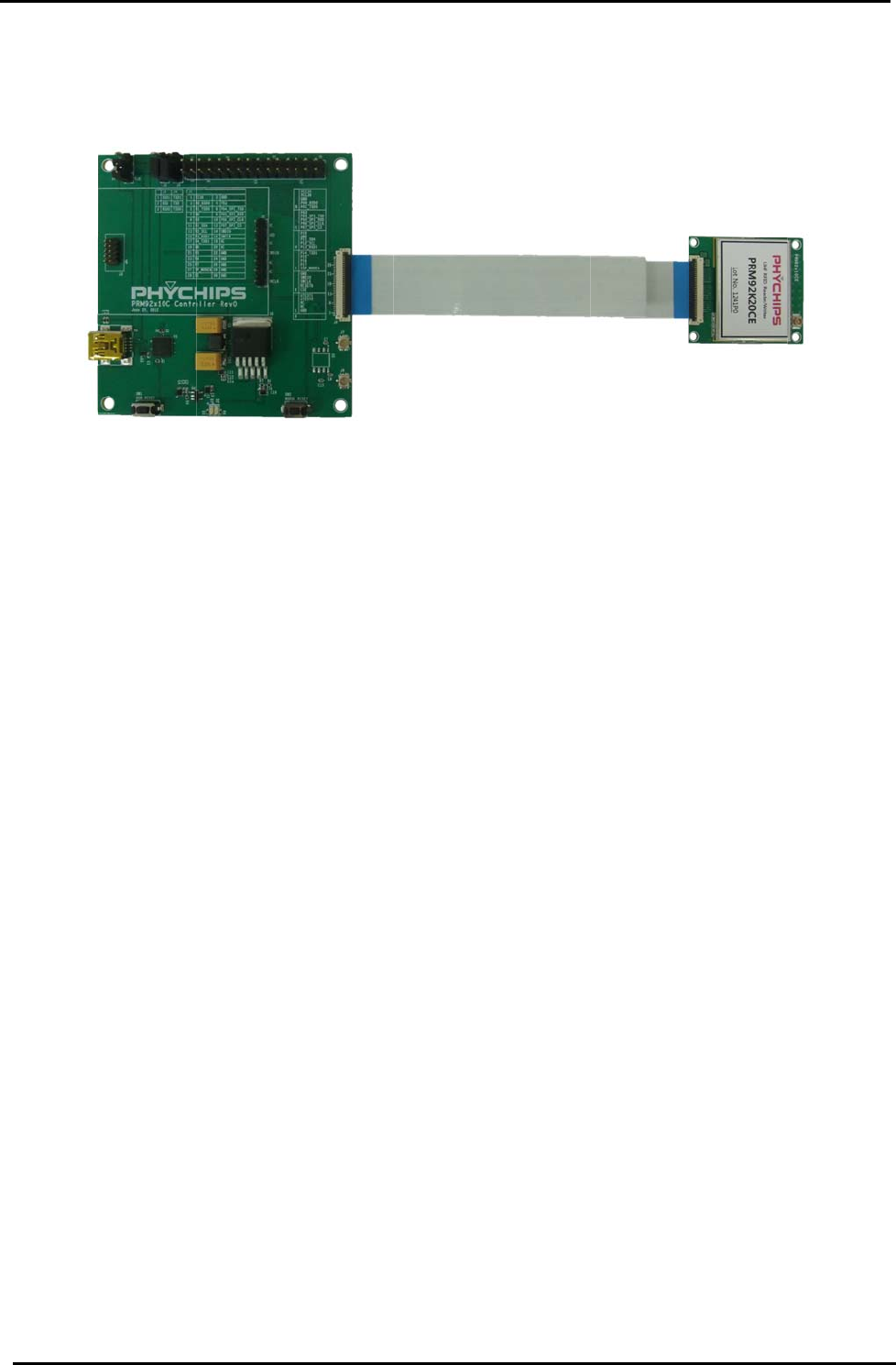
Figure 1 C
o
g
uration
d
es
RF board
R
L : PC inte
r
0 Antenna
U
PM Short D
i
ment CD
R
M92x20C
E
n
terface.
m
odule usin
g
o
nnection to
P
r
face board
i
pole)
PRM92x2
E
and PRM9
x
g
PR9200 a
n
P
RM92x10
C
0CE USER’
s
x
10C_CTRL
n
d include T
C
C
_CTRL & P
R
s
MANUAL
–
board. The
C
XO.
R
M92x20C
E
–
PRM92x2
0
PRM9x10C
_
E
4 of 12
0
CE_ADK0
1
_
CTRL boar
d
1
d

28 December 2012 5 of 12
PRM92x20CE USER’s MANUAL – PRM92x20CE_ADK01
2.2 Features
PRM92x20CE is reference designed module of PR9200 and low cost components.
PRM9x10C_CTRL is control board that connects Reader Module to PC, supporting USB-to-UART interface
and DC power management for reader module.
PRM92x20CE
- EPC Gen2 support
- RCP protocol with CRC
- FCC,EN certified
- PR9200, TCXO, Coupler, Antenna port
- Module size : 30mm x 35mm
- U.FL connector for Antenna port (50ohm)
- 30pin FFC connector (PR9200 full IO including I2C, GPIO)
PRM92x10C_CTRL
- Board size: 70mm x 70mm
- DC power supply to USB
- UART based PC interface
- Mini USB connector
- FFC connector for DC supplement & data interface
- 2.54mm pitch application connector (ALL GPIO)
- SWD support
Firmware & GUI
- RCP protocol with CRC
- Read, Write, access, lock, kill operation
- Bi-directional transfer to host microcontroller
- Bi-directional transfer via I2C interface
- Modular and easy to customize to final use case
- Easy to access to GPIOs
28 December 2012 6 of 12
PRM92x20CE USER’s MANUAL – PRM92x20CE_ADK01
3 DK description
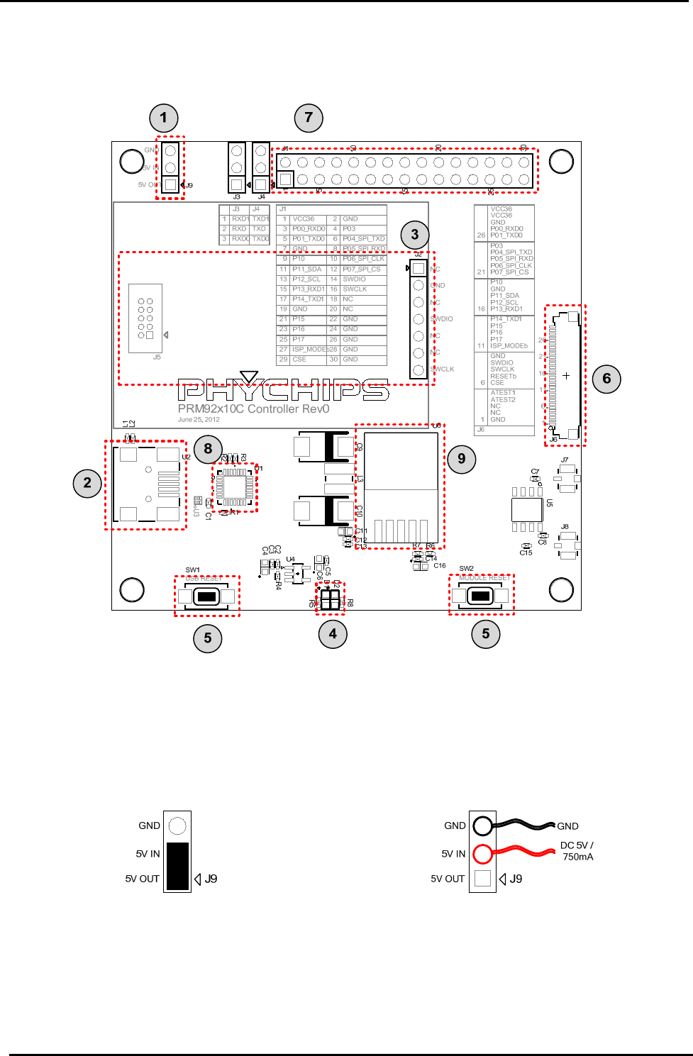
3.1 PRM92x10C_CTRL
Figure 2
3.1.1 Power connector ①
This is 3-pin connector for power supply to internal LDO of this module (⑨)
If this connector is connected by jumper, PRM92x20CE is powered by USB 5V. Also you can connect external
power through this connector pin.
(A) When USB power is used (Default) (B) When External power is used
Figure 3 Power connector
3.1.2 Mini USB port ②
Connect mini-USB port to PC using mini-USB cable enclosed in the package
PRM92x20CE can connect PC through UART and be supplied DC power.
28 December 2012 7 of 12
PRM92x20CE USER’s MANUAL – PRM92x20CE_ADK01
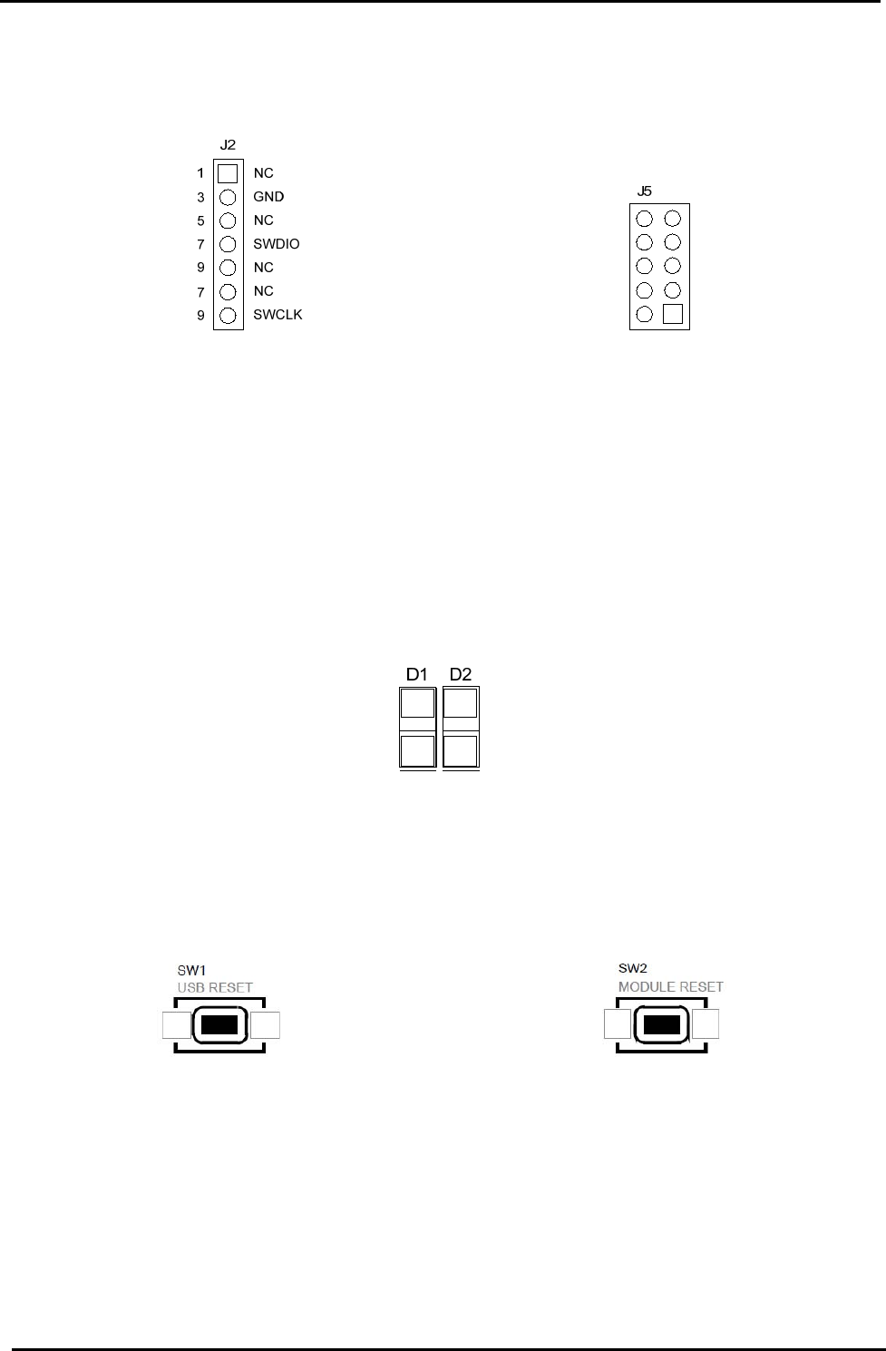
3.1.3 SWD port ③
In order to debug or firmware download, this SWD port is connected to H/W debugger such as ULINK2 and X-
LINK
(A) X-LINK port (B) ULINK2 port
Figure 4 SWD port
[Notice] SWD port power (3.3V) is provided by ULINK2 or X-LINK adapter. Please check jumper setting of
adapter (refer to ULINK2 user’s guide, http://www.keil.com/support/man/docs/ulink2/ulink2_hw_jumpers.htm)
3.1.4 LED part ④
PRM9x10C_CTRL has two LED. One indicate POWER, the other indicate ACTIVE.
When DC power is normally supplied, “POWER” LED is ON. When RFID reader is ready, “ACTIVE” LED is
ON. “ACTIVE” LED is connected to GPIO(P07) of PRM92x20CE and change that function in Firmware
Figure 5 PRM92x20CE_CTRL LED
3.1.5 RESETb button ⑤
This button is used when user want to reset PRM92x20CE and CP2102.
(C) USB Reset (D) Module Reset
Figure 6 Reset button
3.1.6 FFC connector ⑥
30pin FFC connector has used for interconnection with PRM92x20CE

28 December 2012 8 of 12
PRM92x20CE USER’s MANUAL – PRM92x20CE_ADK01
3.1.7 Application connector ⑦
User can connect GPIO, SPI, I2C through application connector and use PRM92x20CE MCU all IO function.
This connector has 2.54mm pitch. Each pin location help user connect IO in many way.
28
26
24
22
20
18
16
14
12
10
8
6
4
2
27
25
23
21
19
17
15
13
11
9
7
5
3
1
ISP_MODEb
P17
P16
P15
GND
P14_TXD1
P13_RXD1
P12_SCL
P11_SDA
P10
GND
P01_TXD0
P00_RXD0
VCC36
GND
GND
GND
GND
NC
NC
SWCLK
SWDIO
P07_SPI_CS
P06_SPI_CLK
P05_SPI_RXD
P04_SPI_TXD
P03
GND
29CSE 30 GND
Figure 7 Application connector
3.1.8 USB-to-UART ⑧
PRM92x10C_CTRL use CP2102 (Silicon Labs) as USB-to-UART bridge. In order to connect PRM92x20CE to
PC, user must install driver at first time.
3.1.9 LDO ⑨
This LDO make 3.6V power supply voltage for PR9200 and TCXO.

28 December 2012 9 of 12
PRM92x20CE USER’s MANUAL – PRM92x20CE_ADK01
4 Specifications
Parameter Symbol Min Typ Max Unit
PRM92x10C_CTRL supply voltage 5 V
PRM92x10C_CTRL output voltage VDD_36 3.6 V
PRM92x10C Current consumption in active
mode IOP 550 mA
TX output maximum power
1
P
OUT 25 dBm
Frequency range fC 917.1 926.9 MHz
1. Current board max power is about 25dBm.

28 December 2012 10 of 12
PRM92x20CE USER’s MANUAL – PRM92x20CE_ADK01
5 Address Information
PHYCHIPS Inc.
#204 Migun Techno world 1, 533 Yongsan-dong, Yuseong-gu, Daejeon, Korea, 305-500
http://www.phychips.com
sales@phychips.com
Tel: +82-42-864-2402
Fax: +82-42-864-2403
Disclaimer: PHYCHIPS reserves the right to make changes to the information in this document without
prior notice. The purchase of PHYCHIPS products does not convey any license under patent rights owned
by PHYCHIPS or others. PHYCHIPS does not assume any responsibility for the use of this product. It is the
customer’s responsibility to make sure that the system complies with regulations.
© 2012 PHYCHIPS Inc. All rights reserved. The reproduction of this document is NOT allowed without
approval of PHYCHIPS Inc.

28 December 2012 11 of 12
PRM92x20CE USER’s MANUAL – PRM92x20CE_ADK01
[Appendix1] Channel Number Table
1. US band
Channel Channel Frequency Channel Channel Frequency
1 917.10 MHz 26 922.10 MHz
2 917.30 MHz 27 922.30 MHz
3 917.50 MHz 28 922.50 MHz
4 917.70 MHz 29 922.70 MHz
5 917.90 MHz 30 922.90 MHz
6 918.10 MHz 31 923.10 MHz
7 918.30 MHz 32 923.30 MHz
8 918.50 MHz 33 923.50 MHz
9 918.70 MHz 34 923.70 MHz
10 918.90 MHz 35 923.90 MHz
11 919.10 MHz 36 924.10 MHz
12 919.30 MHz 37 924.30 MHz
13 919.50 MHz 38 924.50 MHz
14 919.70 MHz 39 924.70 MHz
15 919.90 MHz 40 924.90 MHz
16 920.10 MHz 41 925.10 MHz
17 920.30 MHz 42 925.30 MHz
18 920.50 MHz 43 925.50 MHz
19 920.70 MHz 44 925.70 MHz
20 920.90 MHz 45 925.90 MHz
21 921.10 MHz 46 926.10 MHz
22 921.30 MHz 47 926.30 MHz
23 921.50 MHz 48 926.50 MHz
24 921.70 MHz 49 926.70 MHz
25 921.90 MHz 50 926.90 MHz

28 December 2012 12 of 12
PRM92x20CE USER’s MANUAL – PRM92x20CE_ADK01
[Appendix2] FCC Certification Requirements
1. Caution
Any changed or modifications not expressly approved by the party responsible for compliance could
void the user`s authority to operate this equipment.
2. OEM installation guide
I. OEM integrators must be instructed to ensure that the end-user has no manual instructions to
remove or install the module.
II. This module is to be installed only in mobile of fixed devices. ▪ Mobile device: The devices is
to be generally used in such a way that a separation distance of at least 20cm is normally
maintained between the transmitter`s radiating structures and the body of the user or nearby
persons. ▪ Fixed devices: The device is physically secured at one location and is not able to
be easily moved to another location.
III. To ensure compliance with all non-transmitter functions the host manufacturer is responsible
for ensuring compliance with the module(s) installed and fully operational.
IV. To satisfy FCC exterior labeling requirements, the following text must be placed on exterior of
the end product.
V. An additional permanent label referring to the enclosed module: “Contains Transmitter
Module FCC ID: XYZMODEL1” or “Contains FCC ID: XYZMODEL1” must be used. The host
OEM user manual must also contain clear instructions on how end users can find and/or
access the module and the FCC ID.
3. FCC RF exposure requirements
The antenna used with this module must be installed to provide a separation distance of at least
20cm from all persons, and must not transmit simultaneously with any other antenna or transmitter
except in accordance with FCC multi-transmitter product procedures.
4. FCC authorization for this module
If this module is installed in portable devices or the different antenna configurations are used, the
FCC authorizations are no longer considered valid and FCCID for module cannot be used on the final
product. And the OEM installer will be responsible for re-evaluating the final product including this
module and obtaining separate FCC authorization.
5. Information for importation of radio frequency devices in to the United States
To ensure compliance with all non-transmitter functions the host manufacturer is responsible for
ensuring compliance with the module(s) installed and fully operational. For example, if a host was
previously authorized as an unintentional radiator under the Declaration of Conformity procedure
without a transmitter certified module and a module is added, the host manufacturer is responsible for
ensuring that the after the module is installed and operational the host continues to be compliant with
the Part 15B unintentional radiator requirements. Please see CFR47 Part 2 Subpart J Equipment
Authorization Procedures, KDB784748 D01 v07, and KDB 997198.
6. User Information
This device complies with Part 15 of the FCC`s Rule. Operation is subject to the following to
conditions;
1. This device may not cause harmful interference, and
2. This device must accept any interference received, including interference that may cause
undesirable operation.
This equipment has been tested and found to comply with the limits for a Class B digital device,
pursuant to part 15 of the FCC Rules. These limits are designed to provide reasonable protection
against harmful interference in a residential installation. This equipment generates, uses and can
radiate radio frequency energy and, if not installed and used in accordance with the instructions, may
cause harmful interference to radio communications. However, there is no guarantee that
interference will not occur in a particular installation. If this equipment does cause harmful
interference to radio or television reception, which can be determined by turning the equipment off
and on, the user is encouraged to try to correct the interference by one or more of the following
measures:
- Reorient or relocate the receiving antenna.
- Increase the separation between the equipment and receiver.
- Connect the equipment into an outlet on a circuit different from that to which the receiver is
connected.
- Consult the dealer or an experienced radio/ TV technician for help.