Phychips RED5 RFID Module User Manual Phychips
Phychips Inc. RFID Module Phychips
UserManual.wiki
>
Phychips
>
RED5 User Manual
User Manual
Navigation menu
Upload a User Manual
Namespaces
Wiki Guide
HTML
PDF
Info
Views
User Manual
Discussion / Help
Navigation

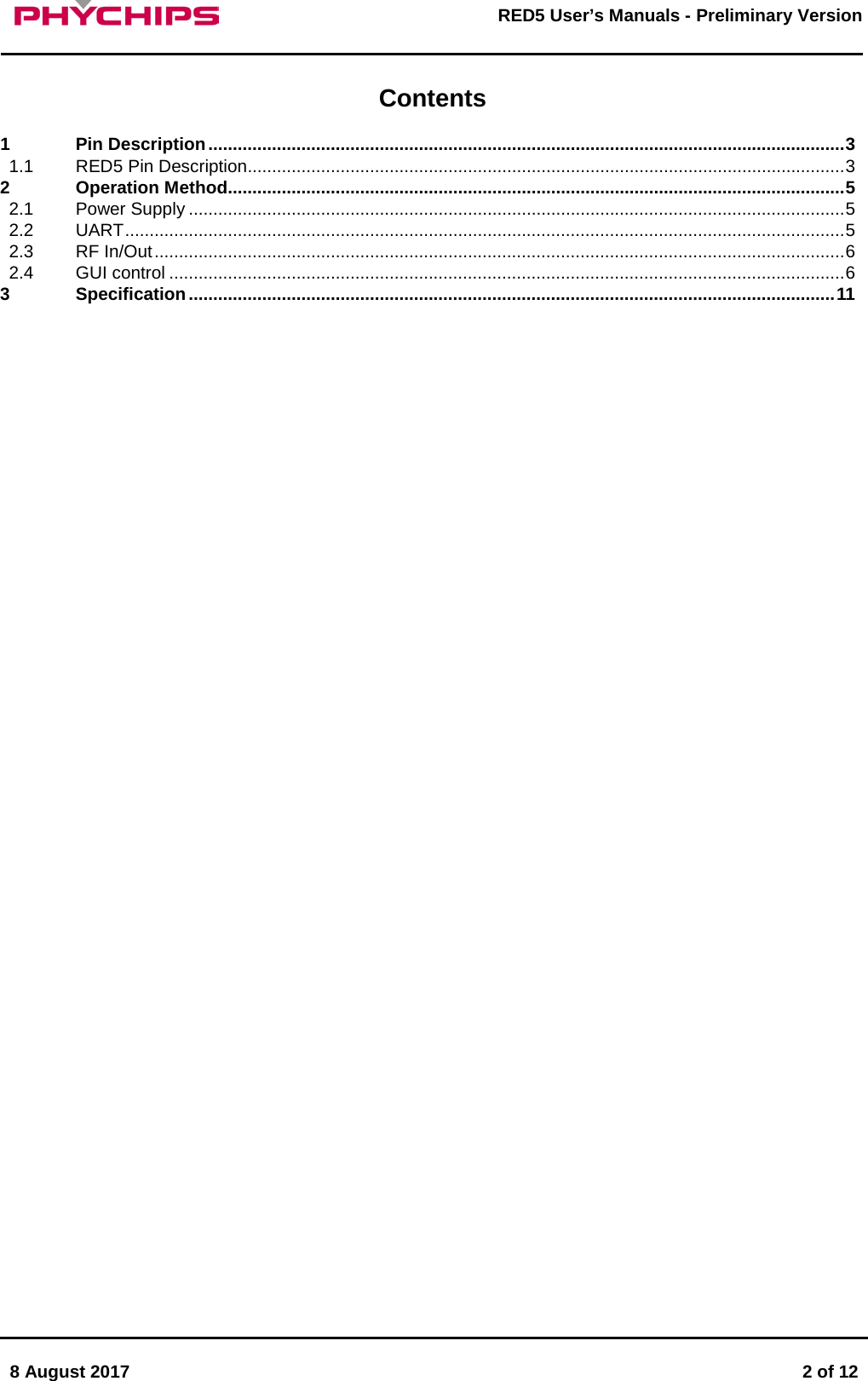
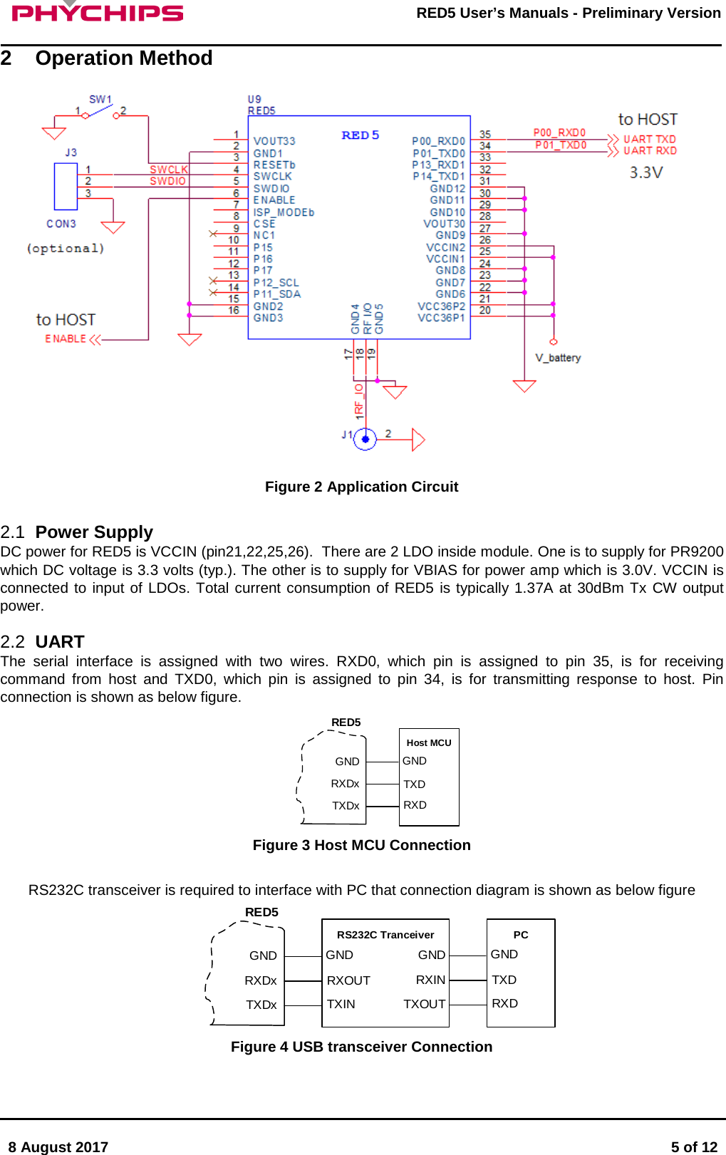
![8 August 2017 3 of 12 RED5 User’s Manuals - Preliminary Version 1 Pin Description GNDRF IOGND1234567891011121314151617181920212223242526272829303132333435VO UT3 3GNDP13_RXD1P01_TXD0RESETbSWCLKSWDIOENABLEISP_MODEbCSENCP15P16P17P12_SCLP11_SDAP00_RXD0P14_TXD1GNDGNDGNDVO UT3 0GNDVCCINVCCINGNDGNDGNDVCCINVCCINGNDRF IOGND1234567891011121314151617181920212223242526272829303132333435VO UT3 3GNDP13_RXD1P01_TXD0RESETbSWCLKSWDIOENABLEISP_MODEbCSENCP15P16P17P12_SCLP11_SDAP00_RXD0P14_TXD1GNDGNDGNDVO UT3 0GNDVCCINVCCINGNDGNDGNDVCCINVCCIN Figure 1 Pin Description 1.1 RED5 Pin Description No. Pin Name Description 1 VOUT33 Internal LDO 3.3V output for PR9200 SOC 2 GND Ground 3 RESETb Reader SOC Reset signal 0: reset 4 SWDIO Serial Wire Debug data in out 5 SWCLK Serial Wire Debug Clock 6 ENABLE Enable pin for RED5. It turns on/off internal LDOs Logic high : enable, Logic low : disable (POWER DOWN) 7 ISP_MODEb When ISP_MODEb is Logic ‘L’, ISP mode is set as shown below table Pin No. 7 12 11 10 Pin Name ISP_MODEb P17 P16 P15 Normal 1 GPIO/INT GPIO/INT GPIO/INT FLASH UART ISP 0 0 0 0 [CAUTION] Except ISP mode, ISP_MODEb should be set “high” for robust stability for FLASH memory 8 CSE Chip Select Enable. Internally connected to VCC33. For the power control of RED5, use ENABLE pin 9 NC Not Connection 10 P15 User configurable general purpose I/O port 11 P16 User configurable general purpose I/O port or External Interrupt 4 12 P17 User configurable general purpose I/O port or External Interrupt 5 13 P12_SCL User configurable general purpose I/O port or I2C Clock The pull-up resistor is always switched on.](https://usermanual.wiki/Phychips/RED5/User-Guide-3501364-Page-3.png)