Physik Instrumente . E821T0002
E821T0002_ E-821 Electronic Module for Energy Harvesting
User Manual: Physik Instrumente E-821 Electronic Module for Energy Harvesting
Open the PDF directly: View PDF ![]() .
.
Page Count: 18
- WP_pi1068_EN.pdf
- Introduction
- Energy Generation with the Piezo Effect
- A Complex System
- Typical Applications for Piezo Energy Harvesting
- Highly Versatile and Durable Patch Transducers
- Power Output as a Function of Load Resistance
- Power Output as a Function of the Excitation Conditions
- Matching Electronics
- Conclusion
- Author
- Company Profile
- Contact
Technical Note
Not authorized for use in the USA and not available in the USA. BRo, 2012-05-21
E821T0002, valid for E-821.EHD
PI Ceramic GmbH Keramische Technologien und Bauelemente, Lindenstraße, 07589 Lederhose, Germany
Telefon +49 36604 882-0, Fax +49 36604 882-4109, E-mail info@piceramic.de, www.piceramic.de
E-821.EHD Piezoelectric Energy Harvesting Evaluation Kit
Documentation
• Technical Note E821T0002 (this document)
• Datasheets for E-876.A12 DuraAct patch transducers and E-821.00 modules for energy harvesting
• Whitepaper “Energy Harvesting Uses The Piezo Effect”
For the motivation and possible applications of energy harvesting with piezoelectric transducers see the
whitepaper in the appendix of this Technical Note.
To ease a first integration of DuraAct transducers PI Ceramic offers the E-821.EHD evaluation kit. With this, you
may try to integrate the PI Ceramic solution in your application, and see if it may work for you.
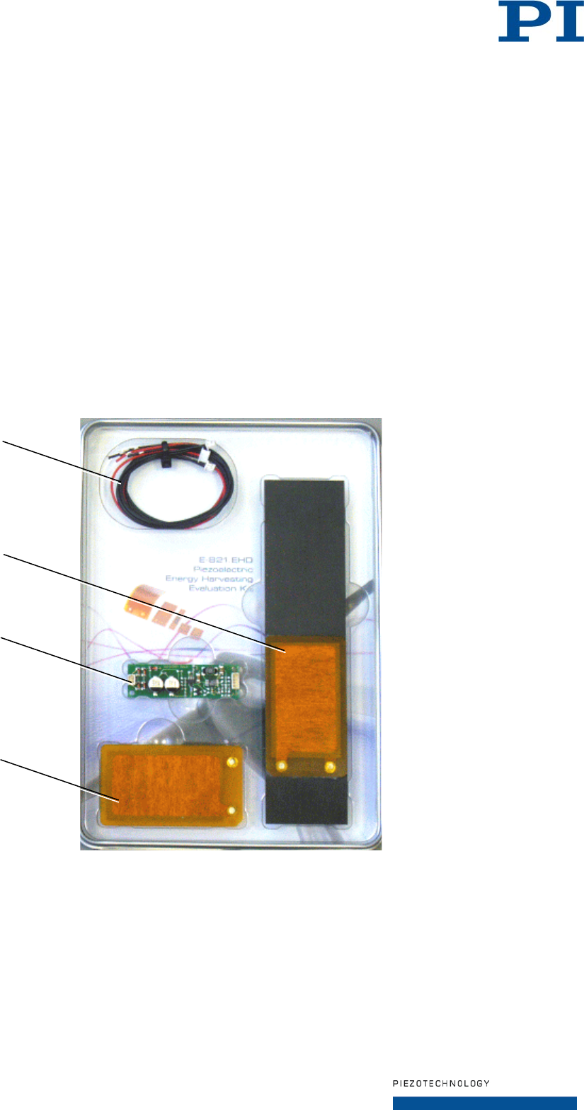
Scope of Delivery
1 Cable set:
• 2 x K040B0428 for connection of P-876.A12 to E-821.00
• 1 x K040B0429 for connection of the electrical load to E-821.00
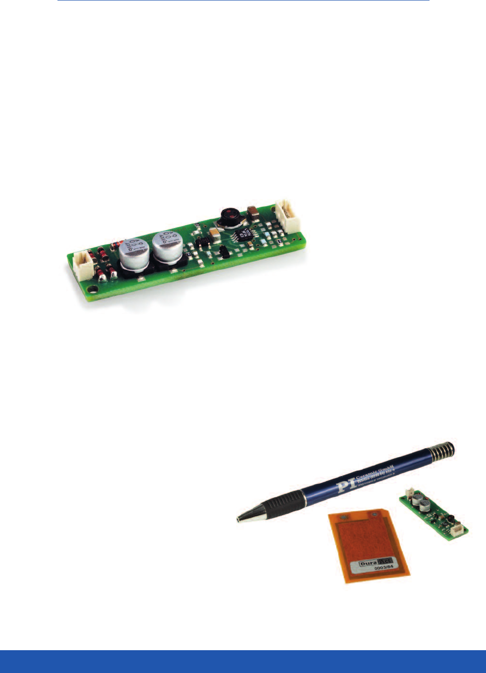
2 P-876KEHD consisting of a P-876.A12 DuraAct patch transducer glued to a plate made of
carbon fiber reinforced plastic
3 E-821.00 module for energy harvesting
4 P-876.A12 DuraAct patch transducer
1
2
3
4
Page 2 / 5
2012-05-21
E821T0002, valid for E-821.EHD
PI Ceramic GmbH Keramische Technologien und Bauelemente, Lindenstraße, 07589 Lederhose, Germany
Telefon +49 36604 882-0, Fax +49 36604 882-4109, E-mail info@piceramic.de, www.piceramic.de
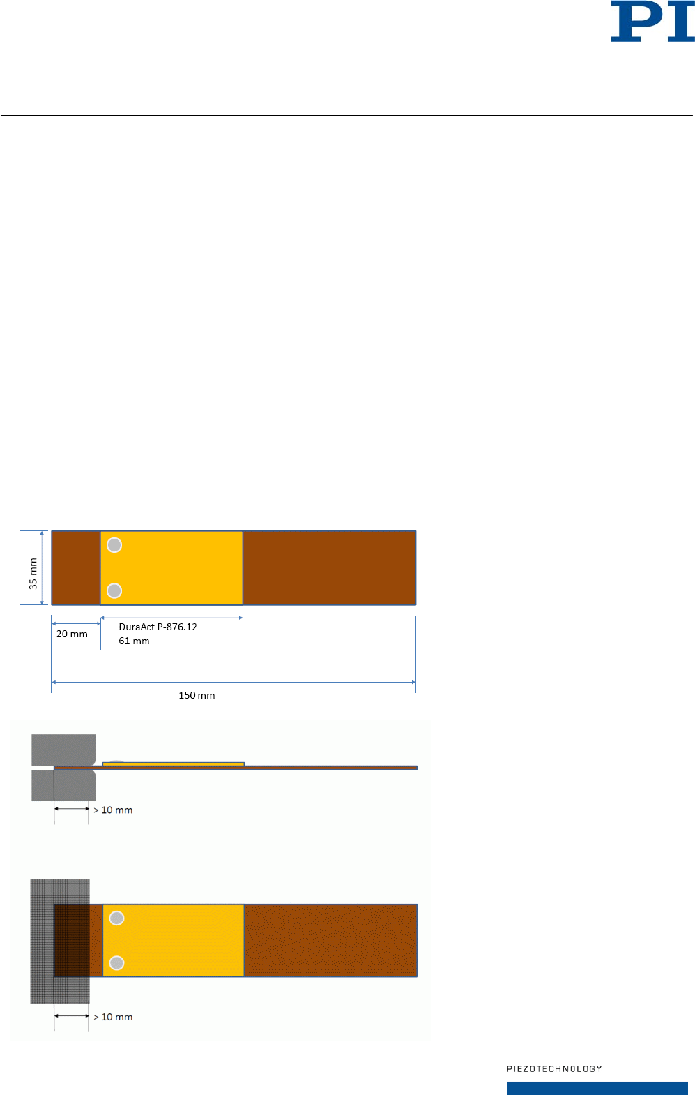
Mounting the DuraAct Patch Transducer
The E-821.EHD kit contains two P-876 DuraAct patch transducers in different integration states to offer you
greatest flexibility for mounting:
• One single patch transducer for gluing on a surface (P-876.A12)
• One patch transducer glued on a plate which must be clamped (P-876KEHD)
Irrespective of the kind of mounting, the bending radius must not be less than 20 mm for the P-876.A12
DuraAct patch transducers.
Gluing a P-876.A12 Patch Transducer on a Surface
Recommended adhesive: two-component epoxy
Roughen the surfaces before gluing.
Make sure to glue the complete surface.
Clamping the P-876KEHD Plate
Chamfer the ends of the clamping bar which point to the plate to avoid a notch effect, see figure below.
Clamp the plate at the short end as near as possible to the DuraAct patch transducer, see figure below.
• Clamping depth: minimum 10 mm
• Clamping width: 35 mm (i.e. clamping over the complete width of the plate)

Page 3 / 5
2012-05-21
E821T0002, valid for E-821.EHD
PI Ceramic GmbH Keramische Technologien und Bauelemente, Lindenstraße, 07589 Lederhose, Germany
Telefon +49 36604 882-0, Fax +49 36604 882-4109, E-mail info@piceramic.de, www.piceramic.de
Connecting DuraAct Patch Transducer and Electrical Load to the E-821.00 Module
Fig. 1: E-821.00 module; location of the soldering points for output voltage selection
marked by circle
Input Signals of the E-821.00 Module
2-pin Molex PicoBlade connector
Pins Values Notes
+Vin
-V
in
max. 40.0 V,
internal limit 15 V
Input voltage from DuraAct patch transducer,
both AC or DC possible
Output Signals of the E-821.00 Module
4-pin Molex PicoBlade connector
Pins Values Notes
GND - -
Vout 3.3 V Output voltage, regulated
Can be changed to 1.8 V or 5.0 V by relocating the 0-ohm solder bridge between
the corresponding soldering points.
5.0 V 3.3 V (default) 1.8 V
Ready 0 V or
9 to 12 V
Output voltage which indicates the charge state of the capacitor of the E-821.00:
• 0 V if the charge state of the capacitor is not sufficient to output Vout
• 9 to 12 V if the capacitor outputs Vout
Output impedance: 1 kOhm
Can be used to switch the connected load on or off.
Vc
5.0 to 40.0 V
Rectified output voltage of storage capacitor
Fig. 2: Block diagram for E-821.00 module

Page 4 / 5
2012-05-21
E821T0002, valid for E-821.EHD
PI Ceramic GmbH Keramische Technologien und Bauelemente, Lindenstraße, 07589 Lederhose, Germany
Telefon +49 36604 882-0, Fax +49 36604 882-4109, E-mail info@piceramic.de, www.piceramic.de
Connecting the Patch Transducer to the E-821.00 Module for Energy Harvesting
For each DuraAct patch transducer, a K040B0428 cable with 2-pin Molex PicoBlade socket and open wires is
included in the scope of delivery.
Solder the two open wires of the K040B0428 cable to the two solder points of the DuraAct patch
transducer. Any assignment is possible due to the non-polarized (AC) output of the DuraAct patch
transducer (is rectified by the E-821.00 module).
After soldering, it is recommended to cover the solder points on the DuraAct patch transducer with
electrical tape.
Connect the DuraAct patch transducer to the E-821.00 module via the 2-pin Molex PicoBlade socket.
Connecting the Electrical Load to the E-821.00 Module for Energy Harvesting
For the connection of the electrical load (in short form: „load“; i.e. the consumer) to the E-821.00 module, the
K040B0429 cable with 4-pin Molex PicoBlade socket and open wires is included in the scope of delivery. With
the K040B0429 cable, the load is supplied by the Vout output voltage of the E-821.00 module.
Example for a load: low-power microcontroller
Solder the two open wires of the K040B0429 cable to the load. Respect the output polarity indicated by
the wire color:
Pin
Color
GND
Black
Vout
Red
Connect the load to the E-821.00 module via the 4-pin Molex PicoBlade socket.
Note: If the load requires a supply voltage higher than Vout, you can use the Vc output voltage instead of Vout. In
this case, make sure that the load is switched on/off using the signal provided by the Ready pin of the E-821.00
module to avoid unwanted discharge of the capacitor. You have to design a custom cable for connection to the
Vc and Ready pins of the E-821.00 module.
Operation
To generate an input voltage for the E-821.00 module and thus charge the capacitor, the DuraAct patch
transducer must be mechanically deformed by force applied with tension or pressure (“excitation”). The bending
radius must not be less than 20 mm for the P-876.A12 DuraAct patch transducers.
For the power output of the E-821.00 as a function of the excitation conditions see the whitepaper in the
appendix of this Technical Note. Note that the measurements described in the whitepaper were made with a P-
876.A12 glued to a plate which was more flexible than the plate used for P-876KEHD in the scope of delivery.
Perform a first test without load. For this test, use the P-876KEHD combination of DuraAct patch
transducer and plate:
1. Make sure that the plate is clamped as described on p. 2.
2. Make sure that the DuraAct patch transducer is connected to the 2-pin connector of the E-821.00
module as described above.
3. Connect an oscilloscope to the Vout pin of the E-821.00 module.
4. Excite the DuraAct patch transducer by tipping the plate or picking at the plate with your fingers at
least 10 times. After at least 10 excitation cycles, the oscilloscope should measure 3.3 V for at least
5 s (output duration can be influenced by the input impedance of the measurement device).
Note that the Vout voltage is output by the E-821.00 module only if the charge state of the capacitor is
sufficient (switching the output on/off is based on an internal threshold).

Page 5 / 5
2012-05-21
E821T0002, valid for E-821.EHD
PI Ceramic GmbH Keramische Technologien und Bauelemente, Lindenstraße, 07589 Lederhose, Germany
Telefon +49 36604 882-0, Fax +49 36604 882-4109, E-mail info@piceramic.de, www.piceramic.de
The following reasons can cause the test to fail (i.e. no voltage can be measured):
o Number of excitation cycles is too low.
o Force applied for mechanical deformation is too low.
If the test without load was successful but supplying a load fails, the load may be too high.
The E-821.00 module can be adapted to your application as follows:
• Change the Vout output voltage to 1.8 V or 5.0 V as described on p. 3
• If a different input voltage range is necessary, contact your PI Ceramic sales engineer for appropriate
modification of the E-821.00 module.
Technical Data
See the data sheets in the appendix of this Technical Note for the technical data of the P-876.A12 DuraAct
patch transducers and the E-821.00 module for energy harvesting.
DuraAct Patch Transducer
BendaBle and RoBust
P-876
Use as actuator, sensor or
energy generator
Cost-effective
Min. bending radii of down to
12 mm
Patch transducer
Functionality as actuator and sensor component. Nominal
operating voltage from 100 up to 1000 V, depending on
the active layer height. Power generation for self-sufficient
systems possible up to the milliwatt range. Can also be
applied to curved surfaces
Robust, cost-effective design
Laminated structure consisting of a piezoceramic plate,
electrodes and polymer materials. Manufactured with
bubble-free injection method. The polymer coating simul-
taneously serves as a mechanical preload as well as an
electrical insulation, which makes the DuraAct bendable
Custom DuraAct patch transducers
Flexible choice of size
Flexible choice of thickness and thus bending ability
Flexible choice of piezoceramic material
Variable design of the electrical connections
Combined actuator/sensor applications, even with
several piezoceramic layers
Multilayer piezo elements
Arrays
Fields of application
Research and industry. Can also be applied to curved
surfaces or used for integration in structures. For adaptive
systems, energy harvesting, structural health monitoring
www.PiceRamic.com
Physik Instrumente (PI) GmbH & Co. KG 2012. Subject to change without notice. Latest releases available at www.pi.ws. 12/04/030
Valid patents
German Patent No. 10051784C1
US Patent No. 6,930,439
Suitable drivers
E-413 DuraAct and PICA Shear Piezo Amplifier
E-835 DuraAct Piezo Driver
Design principle of the transducer
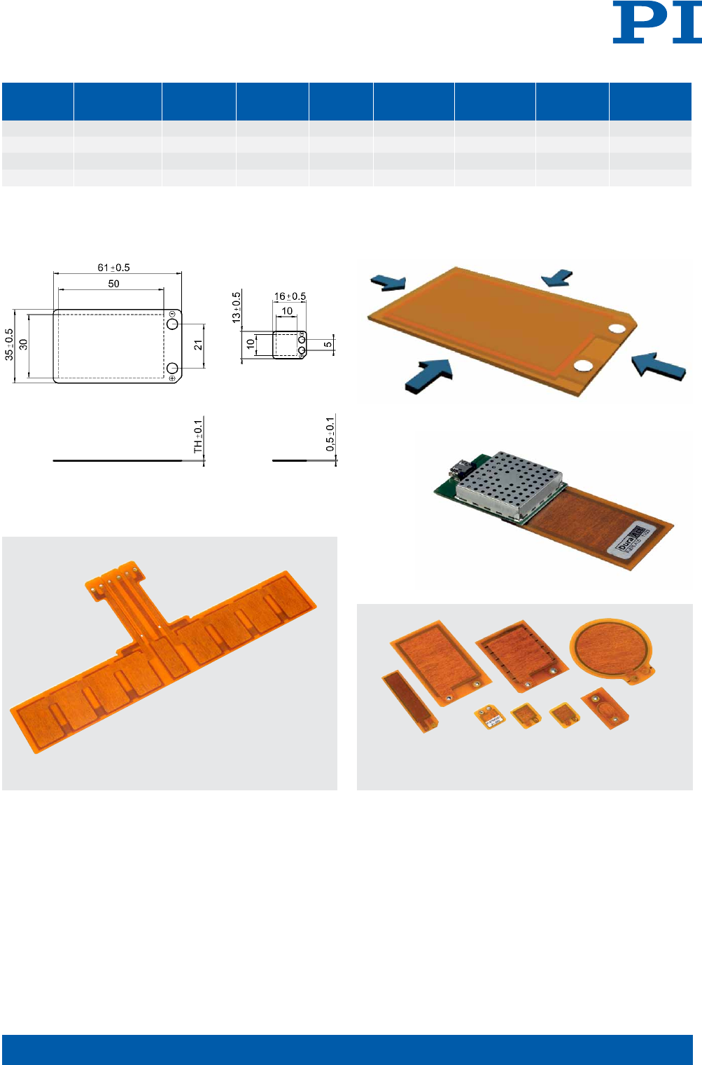
Piezotechnology
Order Operating Min. lateral Rel. lateral Blocking Dimensions Min. Piezo Electrical
Number voltage [V] contraction contraction force [N] [mm] bending ceramic capacitance
[µm/m] [µm/m/V] radius [mm] height [µm] [nF] ±20%
P-876.A11 -50 to +200 400 1.6 90 61 × 35 × 0.4 12 100 150
P-876.A12 -100 to +400 650 1.3 265 61 × 35 × 0.5 20 200 90
P-876.A15 -250 to +1000 800 0.64 775 61 × 35 × 0.8 70 500 45
P-876.SP1 -100 to +400 650 1.3 280 16 × 13 × 0.5 - 200 8
Piezo ceramic type: PIC 255
Standard connections: Solder pads
Operating temperature range: -20 to 150°C
Custom designs or different specifications on request.
P-876.A (left), P-876.SP1 (right), dimensions in mm
When arranged in an array, DuraAct patch transducers allow, for example,
the reliable monitoring of larger areas
When a voltage is applied, the DuraAct patch transducer contracts laterally
DuraAct patch transducers can be manufactured in various shapes
Electronic modules for sensor data processing,
controlling the DuraAct actuator or harvesting energy
can be connected close to the transducer
Electronic Module for Energy Harvesting
U S I N G P I E Z O A C T U AT O R S F O R E N E R G Y G E N E R AT I O N
E-821
ꔴConstant output voltage
ꔴUsable energy 8.7 mJ
ꔴUses pulsed or continuous
excitation
ꔴAdaptation to customer
application on request
© Physik Instrumente (PI) GmbH & Co. KG 2012. Subject to change without notice. Latest releases available at www.pi.ws. R1 12/05/21.0
Related Products
P-876 DuraAct Patch Transducers
P-882 – P-888 PICMA®Stack Multilayer Piezo Actuators
The E-821 energy harvesting electronics is designed to work best with P-876
DuraAct patch transducers
OEM electronic module for energy harvesting
For generating energy from vibration. Use in combination
with DuraAct patch transducers. Adjustable output
voltage. Processes input currents between 20 µA and
40 mA, voltage peaks are limited to 15 V. Custom version
for operation with piezo stack actuators on request
Fields of application
Autonomous power supplies, e.g. for wireless sensor
networks
L I N E A R A C T U A T O R S & M O T O R S | W W W . P I . W S
E-821.00
Function Electronic module for energy harvesting
Channels 1
Min. input current 20 µA
Max. input current 40 mA
Max. continuous input power 500 mW
Output voltage 3.3 V (adjustable from 1.8 to 5.0 V)
Output power (80 ms) 100 mW
Usable energy at the output (200 µF) 8.7 mJ
Interface and operation
Piezo element (voltage input) 2-pin connector
Voltage output 4-pin connector
Miscellaneous
Operating temperature range 0 to 50°C
Dimensions 48 × 15 × 7 mm
Mass 3.5 g
Material SMD board
Typ. current consumption 15 µA during charging
Typ. power consumption 30% of the converted power
Energy can only be released when the threshold voltage level VH has been
reached. A constant voltage is available at the output
L I N E A R A C T U A T O R S & M O T O R S | W W W . P I . W S
Piezo Actuators &
Components Patches,
Benders, Tubes, Shear
NanometrologyHexapod Systems
Micropositioning
Appendix Nanopositioning &
Piezoelectrics
Ask about custom designs!
Not authorized for use in the USA and not available in the USA.
DuraAct patch transducers, which are available in many different designs, can be
adapted to the application
To dimension an energy harvesting system correctly, all important boun-
dary conditions must be known and taken into account. The principle
itself is simple: Ambient vibrations produce a charge separation in the
piezoceramic DuraAct transducer. The electronic circuitry in the E-821
module then ensures a sufficiently stable output voltage that can be
adjusted to the load.

WHITEPAPER
Energy Harvesting Uses
the Piezo Effect
DURAACT PIEZO TRANSDUCER PLUS MATCHING ELECTRONICS
DIPL.-PHYS. BIRGIT SCHULZE JULY 2011

Energy Harvesting Uses the Piezo Effect – Page 2
Introduction 3
Energy Generation with the Piezo Effect 3
A Complex System 4
Typical Applications for Piezo Energy Harvesting 4
Highly Versatile and Durable Patch Transducers 4
Power Output as a Function of Load Resistance 5
Power Output as a Function of the Excitation Conditions 6
Matching Electronics 6
Conclusion 7
Author 7
Company Profile 8
Contact 8
Energy Harvesting Uses the Piezo Effect – Page 3
Introduction
The term Energy Harvesting is popularly used when
electricity is generated from sources such as ambient
temperature, vibrations or air flows. Since there are now
electronic circuits whose power requirement is of the
order of milliwatts, even though its energy yield is rela-
tively low, energy harvesting with piezo-based solutions
is always of great interest in situations where electricity
cannot be supplied via power cables and one wants to
avoid batteries and the maintenance effort required.
Fig. 1 Energy harvesting, also known as power harvest-
ing or energy scavenging can be based on a number of
physical effects. Piezoelectric crystals are also ideal
here, for example (Physik Instrumente (PI))
Energy harvesting (Fig. 1) can be based on a number of
physical effects. Photovoltaic cells are one option, as
are thermoelectric generators which generate electrical
energy from temperature gradients.
It is also possible to receive and energetically use the
energy from radio waves via antennas, as is the case
with passive RFID tags, for example. Piezoelectric
crystals are also ideal for energy harvesting. They gen-
erate an electric voltage when force is applied in the
form of pressure or vibrations, i.e. they use the kinetic
energy available in their environment.
Energy Generation with the
Piezo Effect
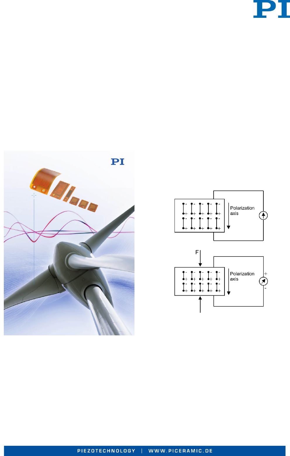
When a piezo crystal mechanically deforms as a result
of a force applied with tension or pressure, charges are
generated which can be measured as a voltage on the
electrodes of the piezo element (Fig. 2), a phenomenon
known as the direct piezo effect.
Fig. 2 Energy generation using the piezo effect (Physik
Instrumente (PI))
This method of charge generation is familiar from gas
ignition systems to generate the ignition voltage, for
example. The charge generated (Q) can be described
by the mathematical expression below:
Q = d ∙ ∆F
The charge constant d (ratio of charge generated to
force applied) in this equation is a material-specific
constant of the order of 10-10 C/N.
Energy Harvesting Uses the Piezo Effect – Page 4
It therefore quickly becomes apparent that the quantity
of charge generated is relatively low. This aspect places
high demands on mechanical systems and electronics
in order to “harvest” the optimum amount of energy.
A Complex System
A universal energy harvesting solution does not exist,
because the energy excitation conditions differ from
application to application. Figure 3 shows the construc-
tion in principle.
Fig. 3 Design of an energy harvesting system (Physik
Instrumente (PI))
To dimension such a system correctly, all important
boundary conditions must be known and taken into
account. Take the energy source, for example:
One needs to distinguish between continuous and
pulsed motions. The requirements of the electric load
must also be taken into consideration, of course: The
important parameters here include the voltage required,
the power and the input impedance, i.e. capacitive or
resistive.
It is then possible to use this data to design and dimen-
sion the transducer including the mechanical system.
Here, PI Ceramic can contribute its years of experience
and comprehensive know-how in the design of custom-
engineered solutions, which benefit very different sec-
tors of industry.
Typical Applications for
Piezo Energy Harvesting
There are many applications where the energy gener-
ated by energy harvesting from the environment is
sufficient and can be used in a worthwhile way.
Although small button cells have quite long useful lives
nowadays, it may make sense to avoid batteries never-
theless, because it is too much effort to test and change
them when the load is installed in a location which is
inaccessible or difficult to reach. Energy harvesting
solutions can then be the means of choice, despite their
complexity. A typical example for this is so-called health
monitoring on the rotor blades of wind turbines.
Further interesting fields for energy harvesting are data
monitoring and transmission in heating and air condi-
tioning technology. If vehicle vibrations are used for
energy generation, products can be continuously moni-
tored during transport without the corresponding sen-
sors having to be connected up or equipped with batter-
ies. This is useful if temperatures have to be recorded
inside closed containers, for example. Rain sensors can
be powered via energy harvesting in the windscreens of
vehicles, and the energy requirements of wireless
ZigBee networks can also often be covered by “harvest-
ing” energy in the environment.
Highly Versatile and
Durable Patch Transducers
In principle, every piezoceramic component or every
piezo actuator can be used for energy harvesting. By
converting mechanical vibrations of a few kilohertz into
electric voltage, a few milliwatts of power can be gener-
ated, and this can be supplied to electrical components,
e.g. processors, sensors or mini-transmitters.
Fig. 4 The table shows the technical data of different
piezo transducers (Physik Instrumente (PI))
Energy Harvesting Uses the Piezo Effect – Page 5
A particularly practical solution is the durable, laminated
DuraAct transducer which PI Ceramic provides in a
wide range of standard designs (Fig. 4 and Fig. 5).
Fig. 5 Highly versatile and durable patch transducers
(Physik Instrumente (PI))
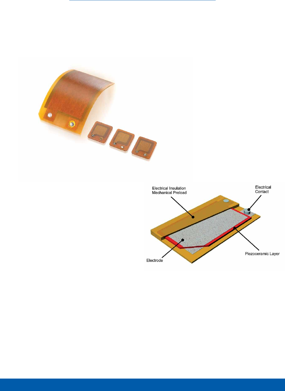
A DuraAct patch transducer consists of piezoceramic
plates or films which are embedded in a polymer to-
gether with their contacts. This mechanically preloads
the brittle ceramic while electrically insulating it at the
same time. The mechanical preloading extends the
loading limits of the ceramic so it can also be applied to
curved surfaces, for example. At the same time the
compact design including the insulation makes it easier
for the user to handle; it is even possible to embed the
patch transducer in a composite material.
The patch transducers ideally have a symmetrical struc-
ture, i.e. when the transducer is bent, the same quantity
of charge with opposite sign is generated on both elec-
trode surfaces; it would not be possible to measure a
potential difference. This makes it necessary to bond
the transducer onto a substrate (e.g. aluminum, CRP or
GRP material), thus producing the conventional bender
structure. Charges can now be generated by fixing the
bender at the edge and displacing it, the charges being
proportional to the stresses or strains introduced into
the ceramic to a first approximation.
A test provides information on how the thickness of the
ceramic affects the energy harvesting characteristics.
To this end, the DuraAct transducers were bonded to
CRP strips and fixed on one edge. A rotating eccentric
disk displaces the bender transducer.
With this set-up it was thus possible to realize the re-
producible fixing and excitation conditions necessary for
the direct comparison of transducers (variation of fre-
quency and displacement).
Power Output as a Function
of Load Resistance
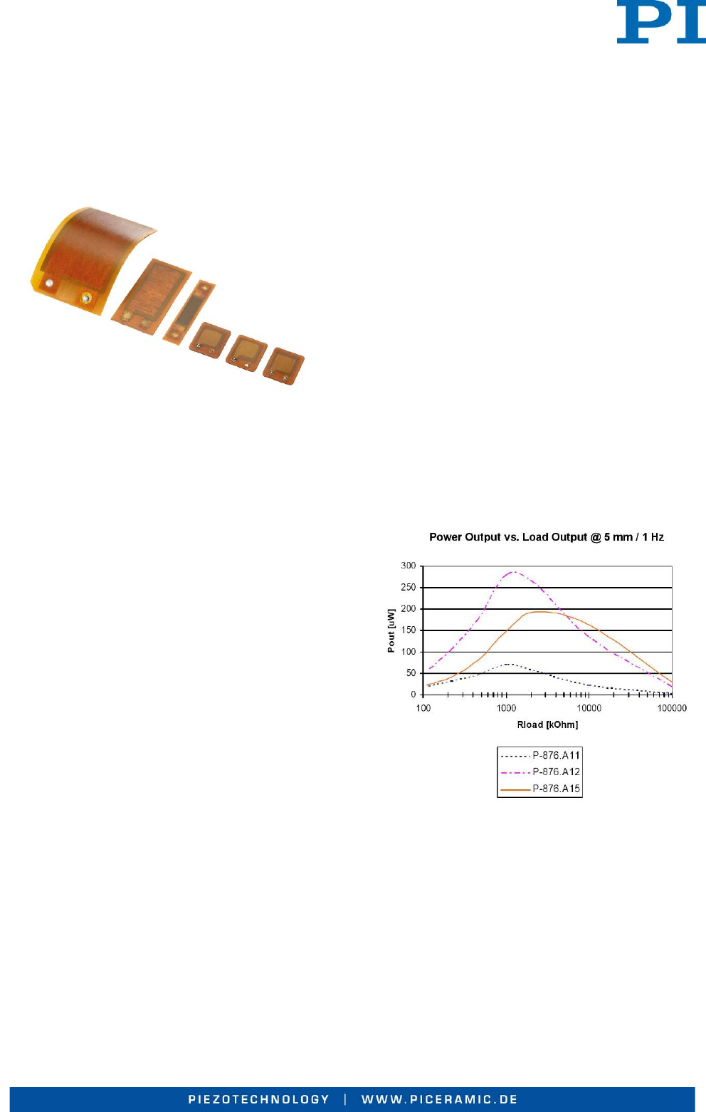
Moreover, it is possible to compare how the CRP bend-
er structures and the various DuraAct transducers (P-
876.A11, -A12 and -A15) bonded on CRP behave at
different load resistances and the same excitation con-
ditions (frequency: 1 Hz, displacement: 5 mm). The AC
voltage from the generator was rectified by a Graetz full
wave bridge rectifier and smoothed with a capacitor (10
µF). The power output was then determined for every
type of DuraAct at different load impedances.
Fig. 6 Power output as a function of the load resistance
(Physik Instrumente (PI))
This showed that every transducer in the test had a
different electrical load range with optimum power out-
put (Fig. 6). The bender structure with the DuraAct P-
876.A12 provides the greatest power output under the
boundary conditions stated. This demonstrates very
well that optimum power output always requires an
optimized transducer design with corresponding power
adjustment.
Energy Harvesting Uses the Piezo Effect – Page 6
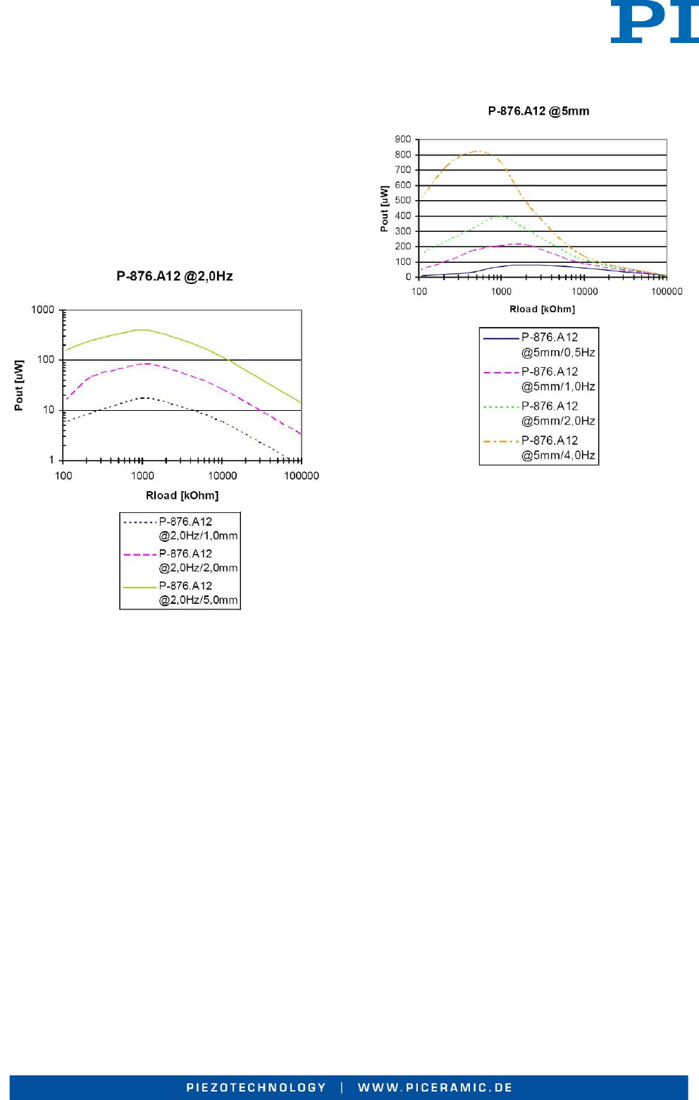
Power Output as a Function
of the Excitation Conditions
The other results of the investigation are restricted to
the bender structure with the DuraAct P 876.A12 patch
transducer.
Fig. 7 Power output as a function of the excitation con-
ditions (Physik Instrumente (PI))
Figure 7 shows the power output as a function of the
displacement. The power output is crucially determined
by the mechanical deformation of the bender structure.
The larger the displacement, the greater the charge and
power generated. It is therefore particularly important to
analyze the energy sources available and to develop a
mechanical design adapted to them which allows opti-
mum conversion of mechanical energy into electrical.
The frequency of the excitation also has a direct effect
on the power output. As Figure 8 shows, there is an
almost linear relationship between power output and
excitation frequency. It is also possible to see a shift of
the optimum load range to smaller values at higher
excitation frequency.
Fig. 8 The relationship between power output and exci-
tation frequency is almost linear (Physik Instrumente
(PI))
Matching Electronics
The test electronics available for piezo energy harvest-
ing include a rectifier with downstream storage capaci-
tor and load switch. They can process alternating and
continuous input voltages. The electronic circuit decou-
ples the load (i.e. the consumer) from the generator and
the energy can be collected and stored over a long
period.
For the charging process of the storage capacitor the
open-circuit voltage of the generator must be higher
than VHigh.
When the voltage level VH is reached after a charging
time t1+t2 the discharge process (supply to a load, t3)
begins. If the voltage available decreases to the value
VLow, no further power output is possible, the storage
capacitor must be charged up again (Fig. 9).

Energy Harvesting Uses the Piezo Effect – Page 7
Fig. 9 Energy is only supplied between the voltage
levels VH and VL (Physik instrumente (PI))
Energy can therefore only be supplied between the
voltage levels VH and VL:
2
)(
2LHel VV
C
W−=
If one varies the capacitor, it is possible to match the
electronics to the power requirement of the load. The
output voltage of the test electronics can be flexibly
adjusted between 1.8 and 5 V. Due to the repeating
phases of “charging” (w), “storing”, “energy output”,
“charging” this solution is particularly suitable for appli-
cations which do not have a continuous power require-
ment, e.g. in wireless sensor networks where the
charge is generated and stored in measurement breaks
and the energy is retrieved for the measurement and
data transmission.
If the piezo transducer, the mechanical system and the
electronics are matched to each other so as to take
account of the application-specific boundary conditions,
piezo-based energy harvesting can be a practical way
of supplying energy in many other applications as well.
Conclusion
The results here show as an example how ambient
energy can be converted to electrical energy and then
be used to supply a corresponding consumer under
specific conditions.
There is no general energy harvesting solution that
serves all purposes. The design of the piezoelectric
transducer, the electronics and the kind of excitation
used substantially determine the outcome and need to
be matched individually for a certain task.
More information on DuraAct piezoelectric patch trans-
ducers is available at:
www.piceramic.com
Author
Dipl.-Phys. Birgit Schulze, Product Manager, Physik
Instrumente (PI) GmbH & Co. KG.

Energy Harvesting Uses the Piezo Effect – Page 8
Company Profile
PI Ceramic from Lederhose/Germany is a subsidiary of
PI (Physik Instrumente in Karlsruhe) and one of the
world’s leading players in the field of actuator and sen-
soric piezo products.
PI Ceramic currently employs over 150 staff, including
no less than 30 engineers, in piezo research, develop-
ment and manufacture. A broad range of expertise in
the complex development and manufacturing process
of functional ceramic components combined with state
of the art equipment ensure high quality, flexibility and
adherence to supply deadlines.
The company supplies piezoceramic solutions for all
important high-tech markets from industrial automation
and the semiconductor industry, medical engineering,
mechanical engineering and high-precision engineering
through to the aeronautics industry and the automotive
sector.
Contact
PI Ceramic GmbH
Lindenstrasse
07589 Lederhose
Phone +49 36 604 / 882 – 0
Fax +49 36 604 / 882 – 4249
Mailto: info@piceramic.de
http://www.piceramic.de/
Physik Instrumente (PI) GmbH & Co. KG
Auf der Römerstraße 1
76228 Karlsruhe
Phone +49 721 / 48 46 – 0
Fax +49 721 / 48 46 – 1019
Mailto: info@pi.ws
http://www.pi.ws

WWW.PICERAMIC.COM
PIEZOTECHNOLOGY
JAPAN
PI Japan Co., Ltd.
Tachikawa
Business Center Bldg. 5F
2-38-5 Akebono-cho
Tachikawa-shi, Tokyo 190-0012
Tel. +81 (42) 526 7300
Fax +81 (42) 526 7301
info@pi-japan.jp
www.pi-japan.jp
PI Japan Co., Ltd.
Hanahara Daini Bldg. #703
4-11-27 Nishinakajima
Yodogawa-ku, Osaka-shi
Osaka 532-0011
Tel. +81 (6) 6304 5605
Fax +81 (6) 6304 5606
info@pi-japan.jp
www.pi-japan.jp
ITALY
Physik Instrumente (PI) S. r. l.
Via G. Marconi, 28
20091 Bresso (MI)
Tel. +39 (02) 665 011 01
Fax +39 (02) 610 396 56
info@pionline.it
www.pionline.it
CHINA
Physik Instrumente
(PI Shanghai) Co., Ltd.
Building No. 7-106
Longdong Avenue 3000
201203 Shanghai, China
Tel. +86 (21) 518 792 98
Fax +86 (21) 687 900 98
info@pi-china.cn
www.pi-china.cn
UK & IRELAND
PI (Physik Instrumente) Ltd.
Trent House, University Way,
Cranfield Technology Park,
Cranfield, Bedford MK43 0AN
Tel. +44 (1234) 756 360
Fax +44 (1234) 756 369
uk@pi.ws
www.physikinstrumente.co.uk
FRANCE
PI France S.A.S.
244 bis, avenue Marx Dormoy
92120 Montrouge
Tel. +33 (1) 55 22 60 00
Fax +33 (1) 41 48 56 62
info.france@pi.ws
www.pifrance.fr
Subsidiaries
USA (East) & CANADA USA (West) & MEXIKO
PI (Physik Instrumente) L.P.
16 Albert St.
Auburn, MA 01501
Tel. +1 (508) 832 3456
Fax +1 (508) 832 0506
info@pi-usa.us
www.pi-usa.us
PI (Physik Instrumente) L.P.
5420 Trabuco Rd., Suite 100
Irvine, CA 92620
Tel. +1 (949) 679 9191
Fax +1 (949) 679 9292
info@pi-usa.us
www.pi-usa.us
SOUTH EAST ASIA
PI (Physik Instrumente)
Singapore LLP
20 Sin Ming Lane
#05-60 Midview City
Singapore 573968
Tel. +65 665 98400
Fax +65 665 98404
info-sg@pi.ws
www.pi-singapore.sg
For ID / MY / PH / SG / TH
KOREA
PI Korea Ltd.
6F Jeongu Bldg.
Cheonho-Daero 1111
Gangdong-gu
138-814 Seoul
Tel. +82 2475 0060
Fax +82 2475 3663
info-kr@pi.ws
www.pi-korea.ws
Headquarters
GERMANY
Physik Instrumente (PI)
GmbH & Co. KG
Auf der Roemerstr. 1
76228 Karlsruhe/Palmbach
Tel. +49 (721) 4846-0
Fax +49 (721) 4846-1019
info@pi.ws
www.pi.ws
PI miCos GmbH
Eschbach
info@pimicos.de
www.pimicos.de
PI Ceramic GmbH
Lederhose
info@piceramic.de
www.piceramic.de
