Pilz and KG PSENCS1 RFID Proximity switch User Manual PSEN cs1 1N de en fr p65
Pilz GmbH & Co. KG RFID Proximity switch PSEN cs1 1N de en fr p65
Contents
- 1. User manual part_1
- 2. User manual part_2
User manual part_1

- 1 -
Sicherheitsbestimmungen
• Das Gerät darf nur von Personen
installiert und in Betrieb genommen
werden, die mit dieser Betriebsanleitung
und den geltenden Vorschriften über
Arbeitssicherheit und Unfallverhütung
vertraut sind. Beachten Sie die VDE-
sowie die örtlichen Vorschriften, insbe-
sondere hinsichtlich Schutzmaßnahmen.
• Entfernen Sie die Schutzkappe erst
unmittelbar vor Anschluss des Geräts
Bestimmungsgemäße Verwen-
dung
Der Sicherheitsschalter PSEN cs1.1n ist
bestimmt für den Einsatz in Sicherheits-
stromkreisen nach EN 60204-1 und
VDE 0113-1.
Der Sicherheitsschalter erfüllt EN 60947-5-3
nur zusammen mit dem Betätiger
PSEN cs1.1 und hierfür zugelassenen
Auswertegeräten.
Gerätebeschreibung
Zum Sicherheitsschalter
PSEN cs1.1n gehört ein codierter Betätiger
(Transponder) PSEN cs1.1.
Der Betätiger besitzt eine elektronische
Codierung. Der Sicherheitsschalter reagiert
nur auf die Betätiger PSEN cs1.1.
Merkmale:
• Für Anwendungen bis Kategorie 4 nach
EN 954-1
• Transpondertechnik
• Zweikanaliger Betrieb
• 2 Sicherheitsausgänge
• LED-Anzeige für:
- Zustand Betätiger
- Zustand Eingänge
- Versorgungsspannung/Fehler
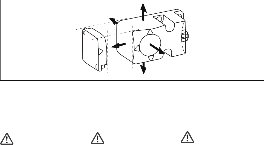
• 5 Betätigungsrichtungen
• Schaltspannung 24 V DC
22178-3FR-02
PSEN cs1.1n
4
D Betriebsanleitung
4
GB Operating instructions
4
F Manuel d'utilisation
Safety Regulations
• The unit may only be installed and
commissioned by personnel who are
familiar with both these instructions and
the current regulations for health and
safety at work and accident prevention.
Ensure VDE and local regulations are
met, especially those relating to safety.
• Do not remove the protective cap until
you are about to connect the device.
Intended Application
The PSEN cs1.1n safety switch is intended
for use in safety circuits in accordance with
EN 60204-1 and VDE 0113-1. The safety
switch meets the requirements of
EN 60947-5-3 only in conjunction with the
actuator PSEN cs1.1 and approved
evaluation devices.
Unit description
The PSEN cs1.1n safety switch comes with
a coded PSEN cs1.1 actuator (trans-
ponder).
The actuator has a electronic coding. The
safety switch only reacts to the actuators
PSEN cs1.1.
Features:
• For applications up to Category 4
of EN 954-1
• Transponder technology
• Dual-channel operation
• 2 safety outputs
• LED display for:
- Status, actuator
- Status, inputs
- Supply voltage/fault
• 5 directions of actuation
• Switching voltage 24 V DC
Consignes de sécurité
• L’installation et la mise en service de
l’appareil doivent être effectuées par une
personne qui s’est familiarisée avec le
présent manuel d’utilisation et avec les
prescriptions relatives à la sécurité du
travail et à la prévention d’accidents.
Respectez les normes locales ou VDE,
particulièrement en ce qui concerne la
sécurité.
• Veuillez retirer le cache de protection
avant de raccorder l’appareil.
Utilisation conforme aux prescrip-
tions
Le capteur de sécurité PSEN cs1.1n est
conçu pour être utilisé dans les circuits de
sécurité selon les normes EN 60204-1 et
VDE 0113-1.
Le capteur de sécurité ne répond aux
exigences EN 60947-5-3 qu'en liaison avec
l'aimant PSEN cs1.1 et les unités de
contrôles adaptées.
Description de l’appareil
Le capteur de sécurité PSEN cs1.1n est
combiné à un actionneur codé
(transpondeur) PSEN cs1.1.
Cet actionneur possède un codage
électronique. Le capteur ne réagit qu’avec
l’élément de commande PSEN cs1.1.
Particularités :
• Pour les applications jusqu’à la catégorie
4 selon EN 954-1
• Technique à transpondeur
• Commande par 2 canaux
• 2 sorties de sécurité
• LED de visualisation pour :
- état de l’actionneur
- état des entrées
- tension d’alimentation/défauts
• 5 sens de manœuvre
• tension commutée 24 V DC
- 2 -
Funktionsbeschreibung
Zwei Mikro-Controller werten die Stromver-
sorgung aus und schalten abhängig davon
die Ausgänge. Die Mikro-Controller
überwachen sich gegenseitig.
• Befindet sich der richtige Betätiger
(Transponder) im Ansprechbereich leiten
die Sicherheisausgänge 12 und 22.
• Befindet sich der Betätiger außerhalb des
Ansprechbereichs (geöffnete Schutztür),
sperren die Sicherheitsausgänge 12 und
22.
Montage
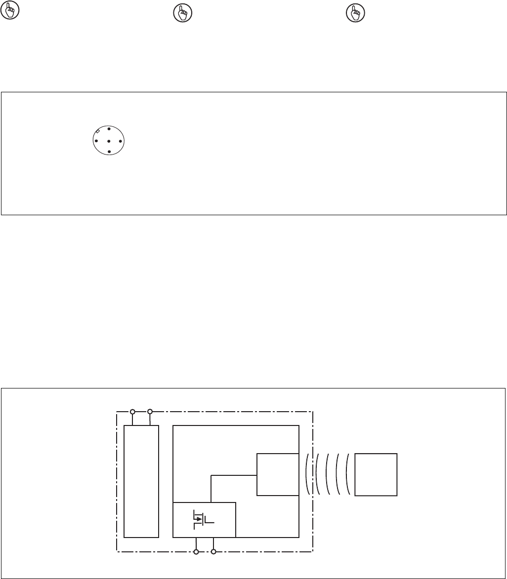
• Die Montagelage ist beliebig. Die aktiven
Flächen von Sicherheitsschalter und
Betätiger müssen jedoch parallel gegen-
überliegend montiert werden:
• Wenn Sie Sicherheitsschalter und
Betätiger in Umgebung von elektrisch
oder magnetisch leitfähigem Material
einbauen, überprüfen Sie die Schaltab-
stände, da Änderungen zu erwarten sind
(Einbaubeispiel mit Schaltabständen
siehe "Technischer Katalog PSENmag
und PSENcode").
Achtung!
Wenn Sie den Sicherheitsschalter
überbündig in elektrisch oder
magnetisch leitfähiges Material
einbauen kann sich außerdem der
Wert für den gesicherten Ausschalt-
abstand sar ändern.
• Befestigen Sie Sicherheitsschalter und
Betätiger ausschließlich mit Schrauben
M5 mit flacher Kopfunterseite (z.B. M5-
Zylinderkopf- oder -Flachkopf-
schrauben). Anzugsdrehmoment max. 1
Nm.
• Der Abstand zwischen zwei
Transponder-Systemen muss minde-
stens 40 cm betragen.
Sicherheitsschalter und Betätiger
• keinen starken Stößen oder Schwingun-
gen aussetzen
• nicht als Anschlag benutzen
Aktive Flächen PSEN cs1.1n/Sensing faces, PSEN cs1.1n/Surfaces actives du PSEN cs1.1n
Function description
Two microcontrollers evaluate the power
supply and switch the outputs accordingly.
The microcontrollers monitor each other.
• If the correct actuator (transponder) is in
the response range, safety outputs 12
and 22 conduct.
• If the actuator is outside the response
range (open safety gate), safety outputs
12 and 22 latch.
Installation
• The unit can be installed in any position.
The sensing faces of safety switches and
actuators, however, must be positioned
opposite each other in parallel:
• If you install safety switches and actua-
tors in the vicinity of electrically or
magnetically conductive material, check
the switching distances, as changes can
be expected (for a typical installation with
switching distances, see the "PSENmag
and PSENcode technical catalogue").
Caution!
If you install the safety switch non-
flush within electrically or magneti-
cally conductive material, the value
for the assured release distance sar
can also change.
• Safety switches and actuators should
only be secured using M5 screws with a
flat head (e.g. M5 cheese-head or pan
head screws). Torque setting, max. 1
Nm.
• The distance between two transponder
systems must be at least 40 cm.
Safety switch and actuator
• Do not expose to heavy shock or
vibration
• Do not use as a limit stop
Description du fonctionnement
Deux microcontrôleurs analysent
l’alimentation et commutent les sorties en
conséquence. Les microcontrôleurs se
contrôlent mutuellement.
• Si le bon actionneur (transpondeur) se
trouve dans la zone de d
étection, les
sorties de sécurité 12 et 22 sont passantes.
•Si
l’actionneur se situe en dehors de la
zone de
d
étection (protecteur mobile
ouvert), les sorties de sécurité 12 et 22 sont
bloquées.
Montage
•
Montage au choix. Cependant, il faut veiller à
ce que la surface active du capteur de sécurité
et celle de l’actionneur soient montées
parallèlement l’une en face de l’autre.
• Si vous installez le capteur de sécurité et
l’actionneur près de matériaux conduc-
teurs électriques ou magnétiques, vous
devez vérifier les distances de commuta-
tion, car des modifications sont à prévoir
(exemple de montage avec distances de
commutation : voir "catalogue technique
PSENmag et PSENcode").
Attention!
La distance de commutation
garantie Sar peut varier en cas de
montage caché du capteur de
sécurité par un matériau conducteur
électrique ou magnétique.
• Pour fixer le capteur de sécurité et
l’actionneur, utilisez uniquement des vis
M5 dont la tête présente une face
inférieure plate (par ex. vis M5 cylindri-
ques ou à tête plate). Couple de serrage
maxi 1 Nm.
• L’écart entre deux systèmes à
transpondeur doit être d’au moins 40 cm.
Le capteur de sécurité et l’actionneur
• ne doivent pas être exposés à des chocs
importants ou à de fortes vibrations
• ne doivent pas être utilisés comme butée
- 3 -
Justage
• Der Sicherheitsschalter kann nur mit dem
zugehörigen Betätiger PSEN cs1.1
verwendet werden.
• Prüfen Sie die Funktion immer mit einem
der zugelassenen Auswertegeräte.
• Die angegebenen Schaltabstände (siehe
technische Daten) gelten nur, wenn
Sicherheitsschalter und Betätiger parallel
gegenüberliegend montiert sind. Andere
Anordnungen können zu abweichenden
Schaltabständen führen. Beachten Sie
den maximal zulässigen Seiten- und
Höhenversatz (siehe "Schaltabstände"
und "Max. Seiten- und Höhenversatz").
Anschlüsse
Wichtig!
Die Farbkennzeichnung für die
Anschlussleitung gilt nur für die als
Zubehör erhältlichen Kabel von Pilz.
Anschluss an Auswertegerät
A1 A2
Power
12 22
Receiver Actuator
Belegung des
5-pol. M12-Stift-
steckers (male)/
Assignment of the
5-pin M12 male
connector/
Brochage du
connecteur mâle
M12 à 5 pôles
1
2
3
5
4
PIN/ Funktion/Function/Fonction Anschlussbezeichnung/ Adernfarbe/Cable
Broche Terminal designation/ colour/Couleur du fil
Désignation des bornes
1: + 24 V UB A1 braun/brown/marron
2: Ausgang Kanal 1/Output, channel 1/ 12 weiß/white/blanc
Canal de sortie 1
4: Ausgang Kanal 2/Output, channel 2/ 22 schwarz/black/noir
Canal de sortie 2
3: 0 V UBblau/blue/bleu
5: nicht anschließen/do not connect/
pas raccordé A2 grau/grey/grie
Adjustment
• The safety switch may only be used with
a corresponding PSEN cs1.1 actuator.
• Always test the function with one of the
approved evaluation devices.
• The stated switching distances (see
Technical details) only apply when the
safety switch and actuator are installed
facing each other in parallel. Switching
distances may deviate if other arrange-
ments are used. Note the maximum
permitted lateral and vertical offset (see
"Switching distances" and "Max. lateral
and vertical offset").
Connections
Important!
The colour marking for the
connection lead only applies for the
cable that Pilz supplies as an
accessory
Connection to evaluation device
Alignement
• Vous ne pouvez utiliser le capteur de
sécurité qu’en liaison avec l’actionneur
PSEN cs1.1 correspondant.
•
Utilisez toujours un appareil de sur-
veillance autorisé pour le contrôle du
fonctionnement.
•
Les distances de commutation (voir
données techniques) ne sont valides que
si le capteur de sécurité et l’actionneur
sont montés parallèlement l’un en face de
l’autre. S’ils sont montés différemment, les
distances de commutation peuvent
différer. Respectez le décalage latéral et
vertical maximal autorisé (voir "Distances
de commutation" et "Décalage latéral et
vertical maximum").
Connexions
Important!
le codage de couleur du câble de
raccordement est valide uniquement
pour les câbles de Pilz disponibles
comme accessoires
Raccordement à l’appareil de sur-
veillance
Die Sicherheitsschalter können mit allen
zugelassenen plusschaltenden
zweikanaligen Auswertegeräten ohne
Querschlusserkennung angeschlossen
werden.
Bitte beachten Sie:
• das Netzteil muss den Vorschriften für
Spannungen mit sicherer Trennung
(SELV, PELV) entsprechen.
• die Ein- und Ausgänge des Sicherheits-
schalters müssen eine sichere Trennung
zu Spannungen über 60 V AC besitzen.
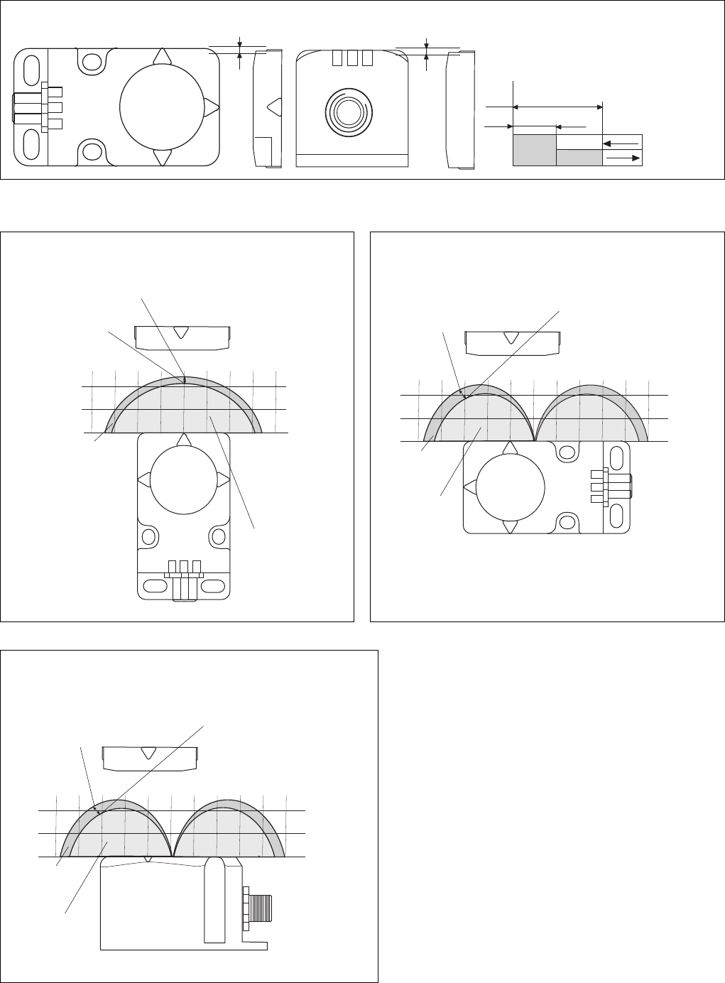
Blockschaltbild
The safety switches can be connected with
all permitted positive switching dual-channel
evaluation devices without detection of
shorts.
Please note:
• The power supply must meet the
regulations for extra low voltages with
safe separation (SELV, PELV).
• The inputs and outputs of the safety
switch must have a safe separation to
voltages over 60 V AC.
Block diagram
Les capteurs de sécurité peuvent être
raccordés à tous les appareils de sur-
veillance à deux canaux, à commutation
positive et sans détection de court-circuits
autorisés.
Tenez compte de ce qui suit:
• Cette alimentation doit être conforme aux
prescriptions relatives aux basses
tensions à séparation galvanique (SELV,
PELV).
• Les entrées et les sorties du capteur de
sécurité doivent posséder une séparation
galvanique pour les tensions supérieures
à 60 V AC.
Schéma de principe
- 4 -
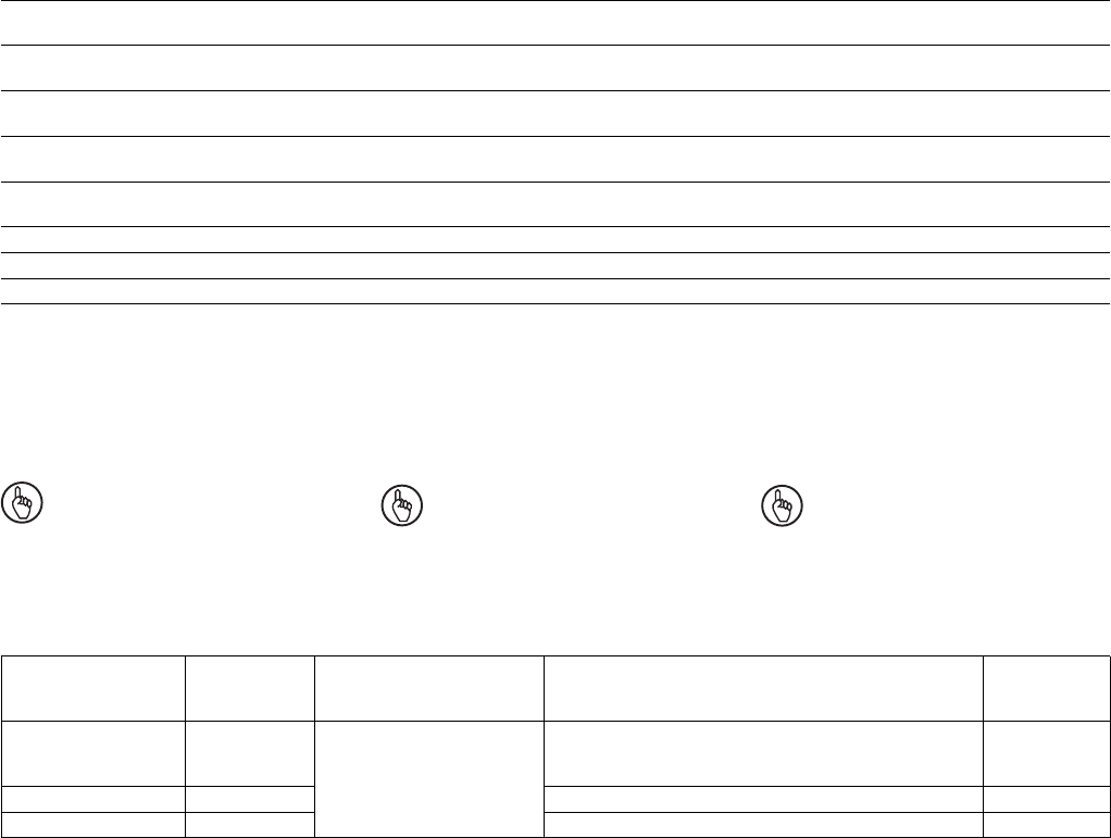
Gesicherter Ausschaltabstand Sar :
max. 40 mm bei allen Höhen- und
Seitenversätzen
Schaltabstände Switching distances
Assured release distance Sar :
max. 40 mm with all vertical and lateral
offsets
Distances de commutation
Distance de coupure protégée Sar :
40 mm maxi pour tous les décalages
latéraux et verticaux
Ein/On/Marche
Aus/Off/Arrêt
s
ao
s
ar
Seitenversatz/Lateral offset/Décalage latéral Höhenversatz/Vertical offset/
Décalage vertical Schaltabstand
Switching distance
Distance de commutation
Seiten- und Höhenversatz Lateral and vertical offset Décalage latéral et vertical
0
10
20
0 102030405060-10-20
-30
-40
0
10
20
Power /Fault
Safety Gate
Input
Versatz in mm/
Offset in mm/
Décalage en mm
Schaltabstand in mm/Switching distance
in mm/Distance de commutation en mm
Typischer Schaltabstand so/
Typical operating distance so/
Portée de travail typique so
Typischer Ausschaltab-
stand /Typical release
distance/Distance de
coupure typique
Hysterese/
Hysteresis/
Hystérésis
0
10
20
0 10203040-10-20-30-40
0
10
20
Power /Fault
Safety Gate
Input
Typischer Schaltabstand
so/Typical operating
distance so/Portée de
travail typique so
Typischer Ausschaltabstand /Typical release distance/
Distance de coupure typique
Hysterese/
Hysteresis/
Hystérésis
Versatz in mm/
Offset in mm/
Décalage en mm
Schaltabstand in mm/Switching
distance in mm/Distance de
commutation en mm
Betätigungsrichtung seitlich/Direction of actuation, side/
Sens de manœuvre : latéral
Ansprechbereich/
Response range/Zone
de déclenchement
Ansprechbereich/
Response range/
Zone de
déclenchement
0
10
20
0 102030405060-10-20
-30
-40
0
10
20
Betätigungsrichtung oben/unten/Direction of actuation up/
down/Sens de manœuvre : en haut/en bas
Versatz in mm/
Offset in mm/
Décalage en mm
Schaltabstand in mm/Switching distance
in mm/Distance de commutation en mm
Typischer Schaltabstand so/Typical operating
distance so/Portée de travail typique so
Typischer Ausschaltab-
stand /Typical release
distance/Distance de
coupure typique
Hysterese/
Hysteresis/
Hystérésis
Ansprechbereich/
Response range/
Zone de
déclenchement
Betätigungsrichtung frontal/Direction of actuation, front/
Sens de manœuvre : frontal

- 5 -
Inbetriebnahme
• Berechnung der max. Leitungslänge Imax
zwischen Auswertegerät und Sicherheits-
schalter pro Kanal:
R
lmax
R
l
/ km
I
max
=
Rlmax = max. Gesamtleitungswiderstand
Rl /km = Leitungswiderstand/km
(siehe Beispiel Technischer Katalog
PSENmag und PSENcode)
Betrieb
Statusanzeigen:
• LED "POWER/Fault" leuchtet grün: Gerät
ist betriebsbereit
• LED "Safety Gate" leuchtet gelb: Betätiger
befindet sich im Ansprechbereich
Fehleranzeige:
• LED "POWER/Fault" leuchtet rot:
Fehlermeldung.
An den LEDS "Safety Gate" und "Input"
werden Blinkcodes zur Fehlerdiagnose
ausgegeben (siehe Technischer Katalog
PSENmag und PSENcode).
Abhilfe: Fehler beheben und Stromversor-
gung unterbrechen.
Commissioning
• Calculating the max. cable runs Imax
between the evaluation device and the
safety switch, per channel:
R
lmax
R
l
/ km
I
max
=
Rlmax = max. overall cable resistance
Rl /km = cable resistance/km
(see example PSENmag and PSENcode
technical catalogue )
Operation
Status indicators:
• "POWER/Fault" LED illuminates green:
The unit is ready for operation
• "Safety Gate" LED illuminates yellow:
Actuator is in the response range
Fault indicator:
• "POWER/Fault" LED illuminates red:
Error message.
Flashing codes for fault diagnosis are
output to the "Safety Gate" and "Input"
LEDs (see PSEN technical catalogue
PSENmag and PSENcode).
Remedy: Rectify fault and interrupt power
supply.
Mise en service
• Calcul de la longueur de câble maximale
Imax entre l’appareil de surveillance et le
capteur de sécurité pour chaque canal :
R
lmax
R
l
/ km
I
max
=
Rlmax = résistance de câblage totale maxi
Rl /km = résistance du câble/km
(voir example catalogue technique
PSENmag et PSENcode)
Exploitation
Affichages d’état :
• La LED "POWER/Fault" s’allume en vert :
l’appareil est opérationnel
• La LED "Safety Gate" s’allume en jaune :
l’actionneur est dans la zone de déclen-
chement
Affichage des erreurs :
• La LED "POWER/Fault" s’allume en
rouge : message d’erreur.
Des codes clignotants servant au diagnos-
tic des erreurs sont émis par les LED
"Safety Gate" et "Input" (voir le catalogue
technique PSENmag et PSENcode).
Aide : éliminer le défaut et couper
l’alimentation électrique.

- 6 -
Technische Daten
Elektrische Daten
Versorgungsspannung UB
Spannungstoleranz
Leistungsaufnahme bei UB
Max. Einschaltstrom an UB
Schaltstrom
Schaltleistung pro Ausgang (12, 22)
Max. Schaltfrequenz
Ausgangskontakte nach EN 954-1
(kurzschlussfest)
Sicherheitsausgänge (S)
Max. Gesamtleitungswiderstand
Rlmax im Eingangskreis
Max. Leitungskapazität an 12, 22
Leerlauf, PNOZ mit
Relaiskontakten
PNOZmulti, PNOZelog, PSS
Zeiten
Überbrückung bei
Spannungseinbrüchen
Einschaltverzögerung
nach Anlegen von UB
Eingänge PSEN cs1.1n
Betätiger PSEN cs1.1
Rückfallverzögerung
Betätiger PSEN cs1.1
Testimpulse Sicherheitsausgänge
12, 22
Gleichzeitigkeit Kanal 1 und 2
Umweltdaten
EMV
Schockbeanspruchung
Schwingungen nach EN 60947-5-2
Frequenz
Amplitude
Verschmutzungsgrad
Bemessungsisolationsspannung
Bemessungsstoßspannungsfestigkeit
Umgebungstemperatur
Mechanische Daten
Hysterese typ.
Gesicherter Schaltabstand sao
Gesicherter Ausschaltabstand sar*
Typischer Schaltabstand so
Anschlussart
Leitung
Schutzart
Gehäusematerial
Abmessungen siehe Abbildung
Gewicht
PSEN cs1.1n
PSEN cs1.1
24 V DC
-20 % ... +20 %
2 W
120 mA
500 mA
12 W
3 Hz
2
1 kOhm
40 nF
70 nF
20 ms
1 s
typ. 13 ms, max. 20 ms
typ. 45 ms, max. 100 ms
typ. 30 ms, max. 260 ms
max. 300 µs
∞
EN 60947-5-3
30 g, 11 ms
10 ... 55 Hz
1 mm
3
250 V
4 kV
-25 ... +70 °C
3 mm
15 mm
40 mm
21 mm
5-pol. M12-Stiftstecker/
5 pin M12 male connector/
Connecteur mâle M12 à 5
pôles
LiYY 5 x 0,25 mm2
IP67
Kunststoff/Plastic/Plastique:
PBT
105 g
20 g
Technical Data
Electrical data
Supply voltage UB
Voltage tolerance
Power consumption at UB
Max. inrush current with UB
Switching current
Breaking capacity per output (12,
22)
Max. switching frequency
Output contacts in accordance with
EN 954-1 (short circuit-proof)
safety outputs (N/O)
Max. overall cable resistance
Rlmax in input circuit
Max. line capacitance with 12,22
No-load, PNOZ with relay
contacts
PNOZmulti, PNOZelog, PSS
Times
Supply interruption before de-
energisation
Switch-on delay
after applying UB
Inputs, PSEN cs1.1n
Actuator, PSEN cs1.1
Delay-on de-energisation
Actuator, PSEN cs1.1
Test pulses safety outputs 12, 22
Simultaneity, channel 1/2
Environmental data
EMC
Shock stress
Vibration in accordance with
EN 60947-5-2
Frequency
Amplitude
Pollution degree
Rated insulation voltage
Rated impulse withstand voltage
Ambient temperature
Mechanical data
Hysteresis typ.
Assured operating distance sao
Assured release distance sar*
Typical operating distance so
Connection type
Cable
Protection type
Housing material
Dimensions, see graphic
Weight
PSEN cs1.1n
PSEN cs1.1
Caractéristiques techniques
Données électriques
Tension d’alimentation UB
Plage de la tension d’alimentation
Consommation pour UB
Courant d’enclenchement max. sur UB
Courant de commutation
Puissance de commutation par
sortie (12, 22)
Fréquence de commutation max.
Contacts de sortie selon EN 954-1
(protégées contre c.c.)
sorties de sécurité (F)
Résistance de câblage totale max.
Rlmax dans le circuit d’entrée
Capacité maximale des conducteurs
sur 12,22
fonctionnement à vide, PNOZ avec
les contacts de relais
PNOZmulti, PNOZelog, PSS
Temporisations
Tenue aux micro-coupures
Temporisation d’enclenchement
après application de UB
Entrées PSEN cs1.1n
Actionneur PSEN cs1.1
Temporisation à la retombée
Actionneur PSEN cs1.1
Impulsions test sorties de sécurité
12, 22
Désynchronisme canaux 1 et 2
Données sur l'environnement
CEM
Résistance aux chocs
Vibrations selon EN 60947-5-2
Fréquence
Amplitude
Niveau d'encrassement
Tension assignée d'isolement
Tension assignée de tenue aux chocs
Température d’utilisation
Données mécaniques
Hystérésis env.
Portée de travail assurée sao
Distance de coupure protégée sar*
Portée de travail typique so
Type de raccordement
Câble
Indice de protection
Matériau du boîtier
Dimensions, voir l'illustration
Poids
PSEN cs1.1n
PSEN cs1.1
- 7 -
Es gelten die 2007-02 aktuellen Ausgaben
der Normen
The version of the standards current at
2007-02 shall apply
Se référer à la version des normes en
vigeur au 2007-02.
* gilt nicht bei überbündigem Einbau in
magnetisch oder elektrisch leitfähiges
Material
* non valable en cas de montage caché
par un matériau conducteur électrique ou
magnétique
* does not apply when installed non-flush
within electrically or magnetically
conductive material
Sicherheitstechnische Kenn-
daten der Sicherheitsausgänge
PL nach EN ISO 13849-1
Kategorie nach EN ISO 13849-1
SIL CL nach EN IEC 62061
PFH nach EN IEC 62061
SIL nach IEC 61511
PFD nach IEC 61511
tM in Jahren
Safety-related characteristics of
the safety outputs
PL in accordance with
EN ISO 13849-1
Category in accordance with
EN ISO 13849-1
SIL CL in accordance with
EN IEC 62061
PFH in accordance with
EN IEC 62061
SIL in accordance with IEC 61511
PFD in accordance with IEC 61511
tM in years
Caractéristiques techniques de
sécurité des sorties de sécurité
PL selon l'EN ISO 13849-1
Catégorie selon l'EN ISO 13849-1
SIL CL selon l'EN CEI 62061
PFH selon l'EN CEI 62061
SIL selon l'EN CEI 61511
PFD selon l'EN CEI 61511
tM en années
PL e (Cat. 4)
Cat. 4
SIL CL 3
4,10E-09
SIL 3
1,10E-04
20
INFO
Bestellnummern und Zubehör finden
Sie im Technischen Katalog oder auf
unserer Internetseite www.pilz.com.
INFORMATION
Order numbers and accessories can
be found in the Technical Catalogue
or on our Internet site www.pilz.com.
INFORMATION
Vous trouverez les références et les
accessoires dans le catalogue
technique ou sur notre site
www.pilz.com.
EG-Konformitätserklärung:
Diese(s) Produkt(e) erfüllen die Anforderun-
gen der Richtlinie 2006/42/EG über
Maschinen des europäischen Parlaments
und des Rates.
Die vollständige EG-Konformitätserklärung
finden Sie im Internet unter www.pilz.com
Bevollmächtigter: Norbert Fröhlich,
Pilz GmbH & Co. KG, Felix-Wankel-Str. 2,
73760 Ostfildern, Deutschland
EC Declaration of Conformity:
This (these) product(s) comply with the
requirements of Directive 2006/42/EC of the
European Parliament and of the Council on
machinery.
The complete EC Declaration of Conformity
is available on the Internet at www.pilz.com
Authorised representative: Norbert Fröhlich,
Pilz GmbH & Co. KG, Felix-Wankel-Str. 2,
73760 Ostfildern, Germany
Déclaration de conformité CE :
Ce(s) produit(s) satisfait (satisfont) aux
exigences de la directive 2006/42/CE
relative aux machines du Parlement
Européen et du Conseil.
Vous trouverez la déclaration de conformité
CE complète sur notre site internet
www.pilz.com
Représentant : Norbert Fröhlich,
Pilz GmbH & Co. KG, Felix-Wankel-Str. 2,
73760 Ostfildern, Allemagne
Typ/
Type/
Type
PSEN cs1.1n
PSEN cs1.1n (switch)
PSEN cs1.1
Stück/
Quantity/
Nombre
1/1
1
1
Merkmale/
Features/
Caractéristiques
Sicherheitsschalter/Betätiger
Safety switch/Actuator
Capteur de sécurité/Actionneur
Sicherheitsschalter/Safety switch/Capteur de sécurité
Betätiger/Actuator/Actionneur
Bestell-Nr./
Order no./
Référence
540 003
540 053
540 080
Bestelldaten/Order reference/Références
Wirkweise/
Operation/
Actionnement
Transpondertechnik/
Transponder technology/
Technique à transpondeur
- 8 -
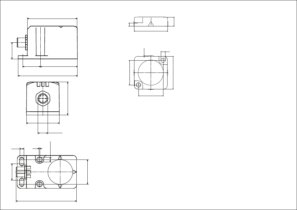
Abmessungen in mm
PSEN cs1.1n PSEN cs1.1
40
11
4
40
5,3
30
30
0,5
72
45
21,5
20
61
M12x1
40
40
5,1 1
5,5
30
20
74
Dimensions in mm Dimensions en mm
- 9 -
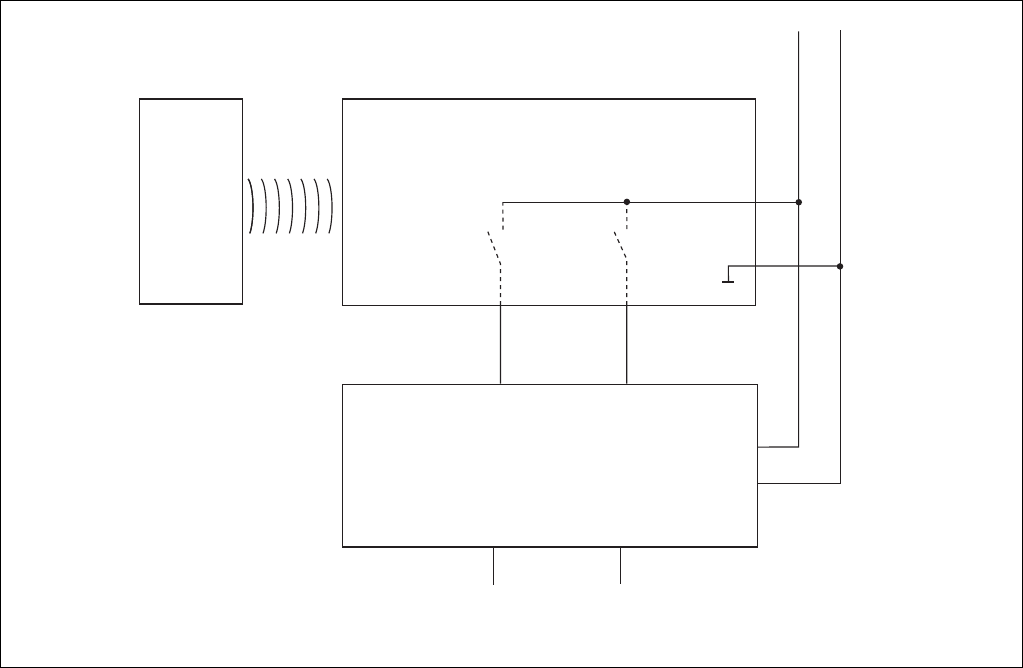
12 22
24 V 0 V
I1 (FS)
A1
A2
A1
A2
Empfänger/
Reciever/
Recépteur
Betätiger/
Actuator/
Actioneur
Auswertegerät/
Evaluation device/
Appareil de surveillance
FS: Fail-safe
ST: Standard
I2 (FS)
Anschlussbeispiele
Einzelschaltung
Connection examples
Independent circuit
Exemples de raccordement
Montage simple
Anschlussbeispiele mit Pilz-Auswertegeräten siehe technischer Katalog PSENmag und PSENcode / Example connections with Pilz
evaluation devices see PSENmag and PSENcode technical catalogue/ Example de raccordement des unités de contrôle de Pilz voir
catalogue technique PSENmag et PSENcode

- 10 -
Originalbetriebsanleitung/Original instructions/Notice originale
22178-3FR-02-2011-06 Printed in Germany
+49 711 3409-444
Technischer Support Technical support Assistance technique
+49 711 3409-444 +49 711 3409-444
...
In vielen Ländern sind wir durch
unsere Tochtergesellschaften und
Handelspartner vertreten.
Nähere Informationen entnehmen
Sie bitte unserer Homepage oder
nehmen Sie Kontakt mit unserem
Stammhaus auf.
Nos filiales et partenaires
commerciaux nous représentent
dans plusieurs pays.
Pour plus de renseignements,
consultez notre site internet ou
contactez notre maison mère.
In many countries we are
represented by our subsidiaries
and sales partners.
Please refer to our Homepage
for further details or contact our
headquarters.
... ...
www.pilz.com
Pilz GmbH & Co. KG
Felix-Wankel-Straße 2
73760 Ostfildern, Germany
Telephone: +49 711 3409-0
Telefax: +49 711 3409-133
E-Mail: pilz.gmbh@pilz.de
www