Pineapple Technology DTXPRO1200U 1.2 KW DTV TRANSMITTER User Manual Manual 2
Pineapple Technology, Inc. 1.2 KW DTV TRANSMITTER Manual 2
Contents
- 1. Manual Section 1
- 2. Manual Section 2
Manual Section 2
PINEAPPLE TECHNOLOGY, INC. VI. BLOCK DIAGRAMS AND PARTS LIST
DTXPRO-1.2KU OPERATING AND SERVICE MANUAL
THE INFORMATION PROVIDED HEREIN IS PINEAPPLE TECHNOLOGY INCORPORATED PROPRIETARY INFORMATION AND
CANNOT BE COPIED OR DISTRIBUTED WITHOUT PRIOR AUTHORIZATION
VI-3
VI. BPUD2.5K6S158-J MASK FILTER

PINEAPPLE TECHNOLOGY, INC. VI. BLOCK DIAGRAMS AND PARTS LIST
DTXPRO-1.2KU OPERATING AND SERVICE MANUAL
THE INFORMATION PROVIDED HEREIN IS PINEAPPLE TECHNOLOGY INCORPORATED PROPRIETARY INFORMATION AND
CANNOT BE COPIED OR DISTRIBUTED WITHOUT PRIOR AUTHORIZATION
VI-4
VI. – BPL5KU-KK HARMONIC FILTER
PINEAPPLE TECHNOLOGY, INC. VI. BLOCK DIAGRAMS AND PARTS LIST
DTXPRO-1.2KU OPERATING AND SERVICE MANUAL
THE INFORMATION PROVIDED HEREIN IS PINEAPPLE TECHNOLOGY INCORPORATED PROPRIETARY INFORMATION AND
CANNOT BE COPIED OR DISTRIBUTED WITHOUT PRIOR AUTHORIZATION
VI-5
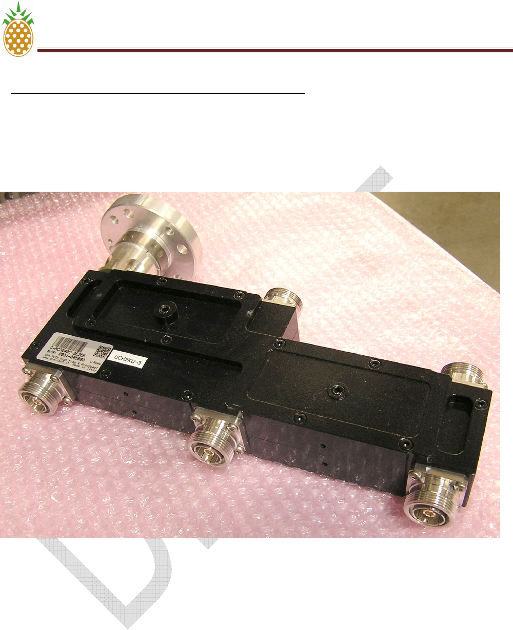
VI. – UCH2KU-3 THREE-WAY HYBIRD COMBINER
PINEAPPLE TECHNOLOGY, INC. VI. BLOCK DIAGRAMS AND PARTS LIST
DTXPRO-1.2KU OPERATING AND SERVICE MANUAL
THE INFORMATION PROVIDED HEREIN IS PINEAPPLE TECHNOLOGY INCORPORATED PROPRIETARY INFORMATION AND
CANNOT BE COPIED OR DISTRIBUTED WITHOUT PRIOR AUTHORIZATION
VI-6
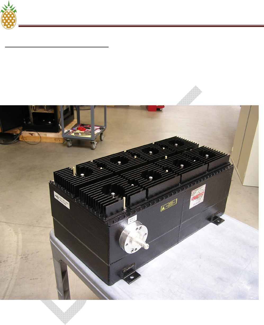
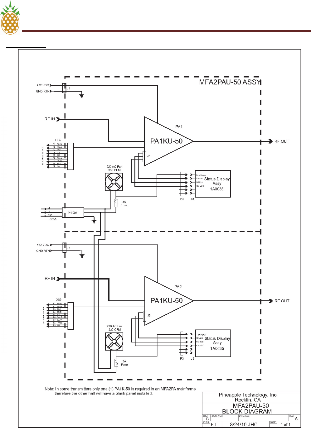
VI. MFA2PA
PINEAPPLE TECHNOLOGY, INC. VI. BLOCK DIAGRAMS AND PARTS LIST
DTXPRO-1.2KU OPERATING AND SERVICE MANUAL
THE INFORMATION PROVIDED HEREIN IS PINEAPPLE TECHNOLOGY INCORPORATED PROPRIETARY INFORMATION AND
CANNOT BE COPIED OR DISTRIBUTED WITHOUT PRIOR AUTHORIZATION
VI-7
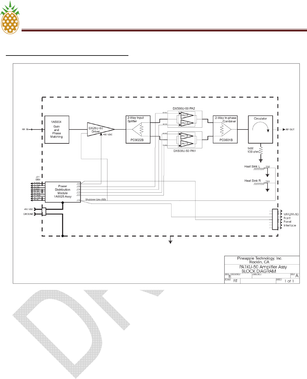
VI. PA1KU-50 AMPLIFIER ASSEMBLY
PINEAPPLE TECHNOLOGY, INC. VI. BLOCK DIAGRAMS AND PARTS LIST
DTXPRO-1.2KU OPERATING AND SERVICE MANUAL
THE INFORMATION PROVIDED HEREIN IS PINEAPPLE TECHNOLOGY INCORPORATED PROPRIETARY INFORMATION AND
CANNOT BE COPIED OR DISTRIBUTED WITHOUT PRIOR AUTHORIZATION
VI-8
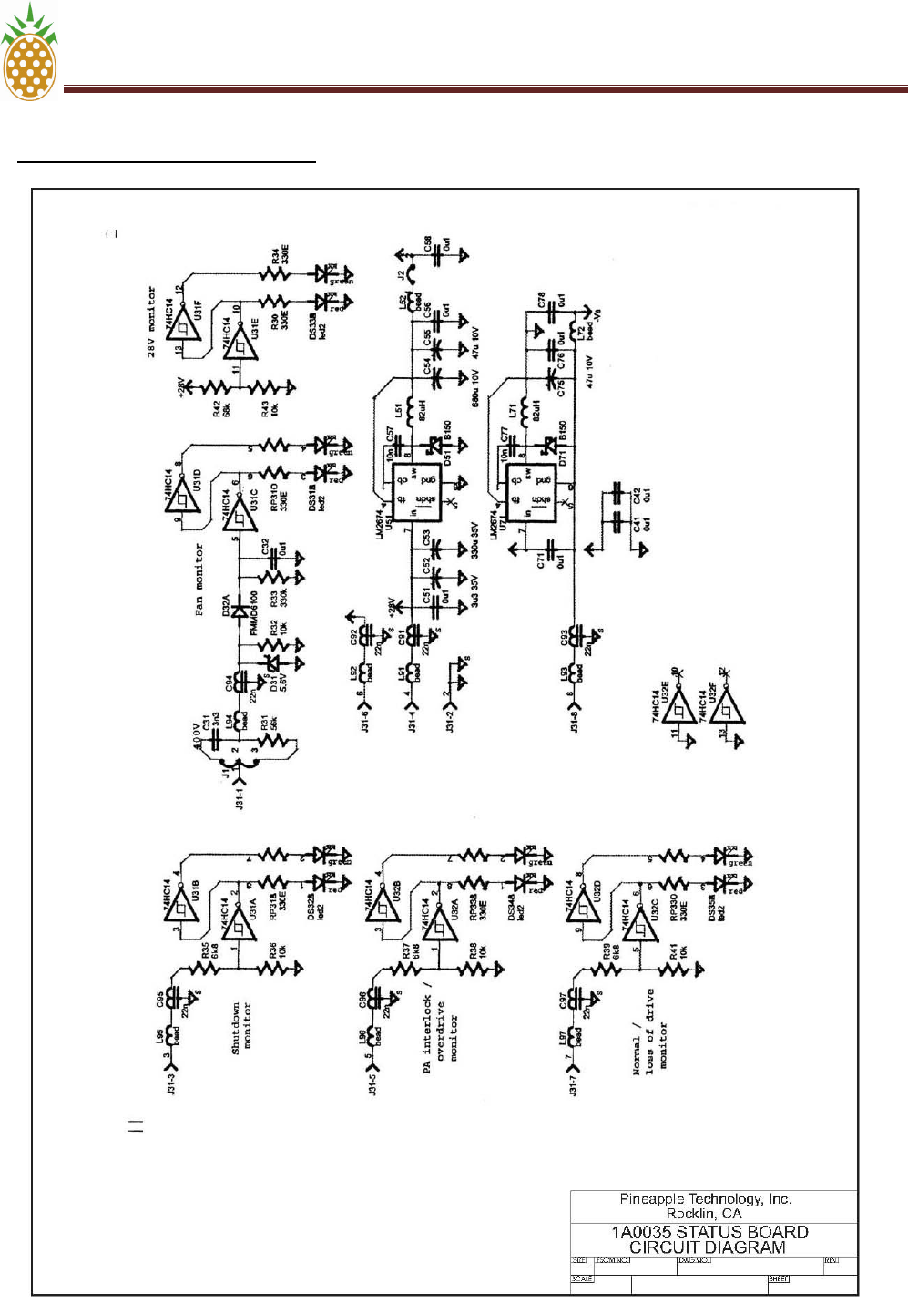
VI. – 1A0035 – STATUS BOARD
PINEAPPLE TECHNOLOGY, INC. VI. BLOCK DIAGRAMS AND PARTS LIST
DTXPRO-1.2KU OPERATING AND SERVICE MANUAL
THE INFORMATION PROVIDED HEREIN IS PINEAPPLE TECHNOLOGY INCORPORATED PROPRIETARY INFORMATION AND
CANNOT BE COPIED OR DISTRIBUTED WITHOUT PRIOR AUTHORIZATION
VI-9
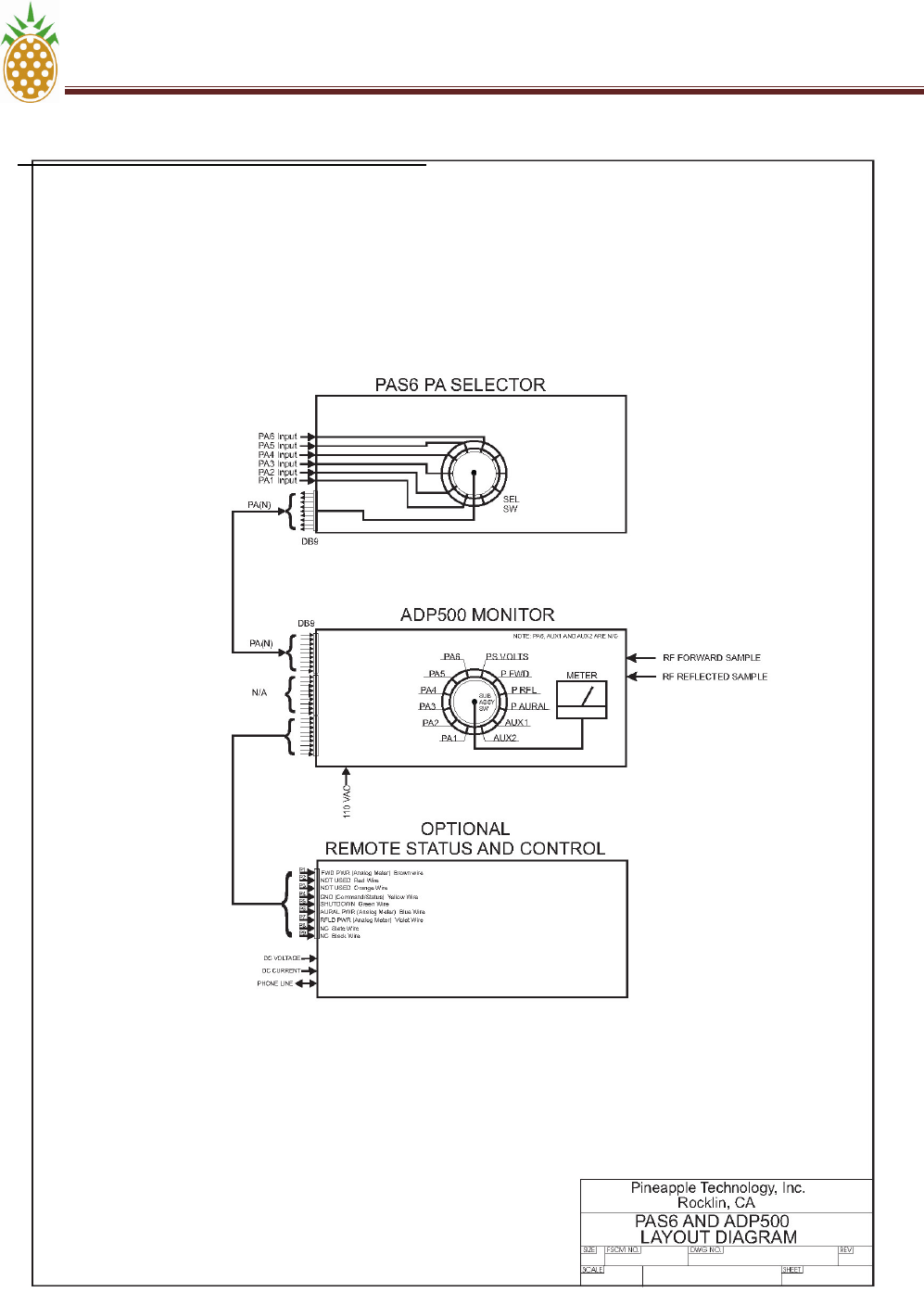
VI. - DC5KC – 1 DIRECTIONAL COUPLER (Includes PAS6 – PA Selector and ADP500 Monitor)

PINEAPPLE TECHNOLOGY, INC. VI. BLOCK DIAGRAMS AND PARTS LIST
DTXPRO-1.2KU OPERATING AND SERVICE MANUAL
THE INFORMATION PROVIDED HEREIN IS PINEAPPLE TECHNOLOGY INCORPORATED PROPRIETARY INFORMATION AND
CANNOT BE COPIED OR DISTRIBUTED WITHOUT PRIOR AUTHORIZATION
VI-10
VI. PARTS LIST
PA1KU-50
QUANTITY PTI PART
NUMBER
DESCRIPTION
1 each DX25U-50 power pallets
2 each DX500U-50 power pallets
1 each 1A5004 Phase and gain matching circuit
1 each PC9022B 2-Way gain & in-phase splitter
1 each PC9601B 2-Way in-phase combiner
1 each Dependent upon
channel number
Circulator
1 each 1A0025 Power distribution module
3 each 310013 Thermal sensors
1 each 481250 Remote monitor port (DB9)
1 each 480401 Front panel status port (Molex)
1 each 451051 Filtered DC input port
1 each CCA102 Type N Panel mounted RF Input port
1 each CCA4002 DIN 7/16 Panel mounted RF Output port
MFA2PA
QUANTITY
PTI PART
NUMBER
DESCRIPTION
2 each 851025B 470 CFM cooling fans
2 each 990199 Air filter assemblies
2 each 1A0035 Front panel status PC boards
1 each MF9100E Main chassis
2 each MF9139 Mechanical slide assemblies
1 each MF9310 AC Inlet filter

SECTION VII
Routine
Maintenance

PINEAPPLE TECHNOLOGY, INC. VII – ROUTINE MAINTENANCE
DTXPRO-1.2KU OPERATING AND SERVICE MANUAL
THE INFORMATION PROVIDED HEREIN IS PINEAPPLE TECHNOLOGY INCORPORATED PROPRIETARY INFORMATION
AND CANNOT BE COPIED OR DISTRIBUTED WITHOUT PRIOR AUTHORIZATION
VII - 2
VII --- ROUTINE MAINTENANCE
The following KEY MAINTENANCE AND PERFORMANCE CHECKS should be made monthly
or more frequently in some environments where dust and rodents are problems. Pineapple
Technology, Inc. recommends that the station provide a data log book to maintain these
records.
DANGER: SOME OF THE RECOMMENDED TESTS REQUIRE THAT THE TRANSMITTER
BE OPERATING IN NORMAL MODE. THIS PROCEDURE MUST BE PERFORMED BY A
BROADCAST ENGINEER. MORE THAN ONE PERSON SHOULD BE PRESENT IN CASE
OF AN ACCIDENT REQUIRING ASSISTANCE. COMMUNICATIONS TO EMERGENCY
SERVICES SHOULD BE AVAILABLE.
TRANSMITTER
• This is an integrated 1.2 KW digital transmitter and is built around three (3) PA1K-50
amplifier assemblies located in two (2) MFA2PA-50 mainframes.
• Record the transmitter forward and reflected power. These readings should be
compared to previous readings to insure normal operation.
• Using the ADP500 record currents for each power LDMOS device in the transmitter.
• Carefully inspect RF Output coaxial cables for excessive heating or discoloration.
• Check DC Power connections on shunt panels and power supplies for over-heating
which could indicate the hardware needs attention.
• Check DC Connections on the PA rear panel.
• Remove and clean the air filters located on the front panel of each MFA2PA-50
mainframe assembly. It is safe to remove the filter while the transmitter is operating.
The filters may be cleaned with a light detergent and dried completely before re-
installing. Spare filters are available from Pineapple Technology, Inc. Request Part
Number P/N 990199 when ordering.
FACILITIES
.
• Clean all air inlet filters and exhaust outlets to ensure that the transmitter is getting
clean unobstructed airflow.
• Perform recommended service on air condition systems.
• Rodent traps or baits should be renewed to keep the facilities clear of these pests
which can cause damage to the transmitter.

SECTION VIII
Adjustments
and
Tuning

PINEAPPLE TECHNOLOGY, INC. VIII – ADJUSTMENTS AND TUNING
DTXPRO-1.2KU OPERATING AND SERVICE MANUAL
THE INFORMATION PROVIDED HEREIN IS PINEAPPLE TECHNOLOGY INCORPORATED PROPRIETARY INFORMATION
AND CANNOT BE COPIED OR DISTRIBUTED WITHOUT PRIOR AUTHORIZATION
VIII - 2
VIII --- ADJUSTMENTS AND TUNING
The DTXPRO-1.2KU is a new series of transmitters offered by Pineapple Technology, Inc. The
latest in LDMOS device and circuit technology are employed to ensure reliable and serviceable
operation for many years.
There are very few adjustments necessary to maintain full service condition. The following will
give the technician a general overview of locations for locating these adjustments:
1. MODULATOR - See details for all adjustments in the DXDPRO-10U Instruction Manual
provided on a CD with your transmitter. Should you have any questions, contact the
Pineapple Technology, Inc Engineering staff for assistance.
2. BPUD2.5K6S158-J - The ATSC digital mask filter provided with your transmitter has
been tuned at the factory and adjustments should not be necessary and are not
recommended. Any attempt to tune or modify this filter will void manufacturer's
warranty.
3. DX500A - This is the main PA board in the transmitter. Under normal operation, no
adjustments are necessary. In the unlikely event that a power transistor has to be
replaced, the bias adjustments should be reset to insure optimum operation of the
transmitter. The following procedure should be followed when making bias
adjustments:
a. Remove the PA1K-50 amplifier assembly from the transmitter and set it up on a
sturdy work bench. The bench should be equipped with a 50 VDC power supply
with current capacity of 10 Amps. A VOM will be required to measure the
voltage drop across the precision resistors located on the monitor board.
b. Attach 50 ohm load resistors to the input port and one to the output port. If this
is not done, severe damage to the PA is possible resulting in costly repair.
c. Connect the 50 VDC supply to the DC ± terminals. DO NOT TURN THE
POWER SUPPLY ON AT THIS TIME.
d. Locate the circuits where bias adjustments are necessary. Adjust only those
circuits where service was performed. Turn the bias adjustment POT's fully
counter clockwise You will find two (2) POT's for each power device with one on
each gate. These are small SMT components and require gentle handling.
e. Locate the current sense resistors on the monitor board. This is a 2 watt .01
ohm precision resistor. There is one for each device.
f. Turn the power supply on and measure the +DC to ensure that it reads +50
VDC.
g. Measure the voltage drop across the precision resistor. This should read zero
(0) VDC. Increase one of the bias POT's slowly till the meter reads 0.009 volts.
Increase the second POT until the reading is 0.018 volts. This completes the
adjustment.

PINEAPPLE TECHNOLOGY, INC. VIII – ADJUSTMENTS AND TUNING
DTXPRO-1.2KU OPERATING AND SERVICE MANUAL
THE INFORMATION PROVIDED HEREIN IS PINEAPPLE TECHNOLOGY INCORPORATED PROPRIETARY INFORMATION
AND CANNOT BE COPIED OR DISTRIBUTED WITHOUT PRIOR AUTHORIZATION
VIII - 3
VIII --- ADJUSTMENTS AND TUNING (Continued)
3. DX500A (Continued)
h. Repeat the adjustment above as necessary to set all circuit that have been
serviced.
NOTICE: DO NOT USE THE BIAS CURRENT INDICATED ON THE MONITOR
PANEL OF THE ADP1000 TO MAKE BIAS ADJUSTMENTS.
1. PA PALLETS - These circuits are "FIXED TURNED" and do not require any field
adjustment. Any questions regarding pallet adjustments should be referred to the
factory.
6. PHASE MATCHED CABLES - If it becomes necessary to replace one of the phase
matched cables, contact Pineapple Technology, Inc. for replacements. These cables
are the ones connected to the input and output ports on the PA1K-50.
7. OUTPUT POWER - The transmitter output power measurement is made using a
calibrated RF POWER MONITORING DEVICE. No adjustments are necessary here.
8. GAIN & PHASE MATCHING - Under normal conditions it is not necessary to make any
gain or phase adjustments in the transmitter. This transmitter is equipped with provision
to adjust phase and gain to ensure minimum power loss in the dump load and
maximum forward transfer power to the antenna. Contact Pineapple Technology, Inc.
for details if this becomes necessary.

SECTION IX
Problem
Solving
and
Troubleshooting

PINEAPPLE TECHNOLOGY, INC. IX--PROBLEM SOLVING AND TROUBLESHOOTING
DTXPRO-1.2KU OPERATING AND SERVICE MANUAL
THE INFORMATION PROVIDED HEREIN IS PINEAPPLE TECHNOLOGY INCORPORATED PROPRIETARY INFORMATION AND
CANNOT BE COPIED OR DISTRIBUTED WITHOUT PRIOR AUTHORIZATION
IX - 2
IX - PROBLEM SOLVING AND TROUBLE SHOOTING
The DTXPRO-1.2KU is a "MODULAR ASSEMBLY" where most of the sub-assemblies can be
removed and or replaced as necessary to maintain full service. To service this transmitter, it is
best to become familiar with the various sub-assemblies by reviewing the transmitter block
diagram and its associated subs shown in the introduction. Any work performed on a transmitter
licensed by the FCC must be performed by qualified personnel.
FAILURE ANALYSIS STARTS WITH THE FOLLOWING ASSUMPTIONS:
1. The transmitter is connected to an AC source which is within the specified voltage range
and has ample power to run the transmitter.
2. The antenna has been checked out and a proper match has been verified.
3. The room temperature is < +35 degrees Celsius (+95 degrees Fahrenheit)
4. There are no restrictions in the air flow in or out of the building.
5. The video and aural signals to the modulator comply with stated specifications.
CHECKING THE WARNING LIGHTS
There are several warning signals visible on the front of the transmitter that will alert the
technician of possible problems. When viewed from the front, all the lights should be GREEN
indicating normal operation. An alert signal is indicated by a RED light. We will focus on RED
alert signals in this section.
MFA2PA ASSEMBLY
FAN FAULT RED indicates that the fuse supplying AC to the fan has failed. The fuses
located just inside the front panel near the top.
CHECK: FUSE AND/OR FAN
DC SUPPLY RED indicates a loss of +50 VDC to PA
CHECK: DC supply voltage to the rear of the PA1K-50
CHECK: DC supply fuse located on the Fuse panel located at the bottom of the
rack in the rear.
CHECK: AUX panel location in the bottom half of the rack being checked for
proper voltage and current readings
NOTE: If all the ALERT lights are on in a given rack, this could indicate that a
breaker has tripped.
CHECK: Circuit breakers located on the front of the ACDIS2 or the sub-panel
breaker located at the MAIN AC supply.

PINEAPPLE TECHNOLOGY, INC. IX--PROBLEM SOLVING AND TROUBLESHOOTING
DTXPRO-1.2KU OPERATING AND SERVICE MANUAL
THE INFORMATION PROVIDED HEREIN IS PINEAPPLE TECHNOLOGY INCORPORATED PROPRIETARY INFORMATION AND
CANNOT BE COPIED OR DISTRIBUTED WITHOUT PRIOR AUTHORIZATION
IX - 3
IX - PROBLEM SOLVING AND TROUBLE SHOOTING (Continued)
SHUTDOWN RED indicates that the PA has been "SHUTDOWN". There are two
possible reasons for this:
1. Heat Sink over temperature thermostat has tripped protecting the PA
CHECK: Air inlet filter for possible restrictions to air flow
CHECK: Fan air flow for possible fan fault
CHECK: Room temperature
Note: Heat sink over temperature fault is indicated by the RED alert
light going ON/OFF in cycles varying in duration depending on air
flow. The PA returns to normal operation automatically when the
problem is corrected.
2. Remote Shutdown by external signals coming from other protection
circuits.
CHECK: Transmitter global protection circuits.
ADP500 MONITOR
The ADP500 is a general purpose test instrument used to display PA status and measure
voltage, and current. When combined with the PAS it is possible to measure the current being
drawn by each PA RF Device. The ADP500 is a diagnostic tool for troubleshooting the
transmitter.
With normal operating conditions, all the LED's on the front panel are GREEN. Red LED's could
indicate a fault in the transmitter that requires attention.

PINEAPPLE TECHNOLOGY, INC. IX--PROBLEM SOLVING AND TROUBLESHOOTING
DTXPRO-1.2KU OPERATING AND SERVICE MANUAL
THE INFORMATION PROVIDED HEREIN IS PINEAPPLE TECHNOLOGY INCORPORATED PROPRIETARY INFORMATION AND
CANNOT BE COPIED OR DISTRIBUTED WITHOUT PRIOR AUTHORIZATION
IX - 4
IX - PROBLEM SOLVING AND TROUBLE SHOOTING (Continued)
PA1 - PA5 LED's are RED This will indicate that the PA Pallet currents are below the 500 ma set
point. This can occur when the PA Power device has failed.
CHECK 1: Select the PA device in question for current display on the
multi-meter. Compare the reading to the station log. If abnormal, it is
possible that a power transistor has failed.
NOTICE: PA5 will go RED when the INHIBIT SWITCH is actuated.
CHECK2: To confirm a failed device, it is necessary to shutdown the
transmitter and remove the PA1K power amplifier assembly and
check the device in question. Use a VOM to check the resistance
from the gate of each 1/2 of the device to ground. If either reading is
below 1K ohm it is likely that the device has failed.
POWER SUPPLY MODULE LED RED
The Power Supply Module has two warning LED's located on the front panel. Normally these
LED's are GREEN indicating that the AC Line voltage and the OVER VOLTAGE circuits are
operating properly. If either LED turns RED the module is question will be turned off and is no
longer supplying power to the transmitter. These modules are "HOT PLUGGABLE" and can be
removed from active service by simply removing it from the main frame. Pineapple Technology,
Inc., does not recommend any attempt to service these modules. Any attempt to service may
void factory warranties. Return the module to Pineapple Technology, Inc., or to the manufacture
for service.
NOTICE: If it becomes necessary to operate the transmitter with a missing supply module,
very little if any performance degrading will be experienced. Check the AUX volt meter for
any indication of a drop in voltage (normally 50 VDC). This drop is caused by the power
supply modules going into "CURRENT LIMIT". It is important that the voltage be around 50
volts ±0.5. If the voltage falls below this point, it can be recovered by reducing the RF
Drive level a small amount in most cases.

SECTION X
Warranty

X -- WARRANTY
The WARRANTY provided by Pineapple Technology, Inc. (PTI) on this transmitter is
detailed below. It should be noted that some of the equipment sub-systems have
warranty coverage by the original manufacture that differs from the standard warranty
provided by PTI Warranty details on equipment falling into this category may be found in
the Manufacturers instruction manual provided with the transmitter. In all cases,
replacement units of this equipment are normally in stock at PTI for quick turn service
support to our customers during the PTI Standard Warranty period.
STANDARD WARRANTY
Seller warrants that each Product sold by it is free of defects in materials and
workmanship. Seller's obligation under said warranty continues for a period of one (1)
year from date of shipment. Repairs or replacement of defective parts shall be the sole
and exclusive remedy under warranty, at Seller option, provided that Seller may, as an
alternative, elect to refund an equitable portion of the purchase price of the product.
THIS WARRANTY IS EXPRESSLY IN LIEU OF AND EXCLUDES ALL OTHER
EXPRESS OR IMPLIED WARRANTIES, INCLUDING BUT NOT LIMITED TO
WARANTIES OF FITNESS FOR A PARTICULAR PURPOSE, USE, OR APPLICATION,
AND ALL OTHER OBLIGATIONS OR LIABILITIES ON THE PART OF THE SELLER,
UNLESS SUCH OTHER WARRANTIES OBLIGATIONS OR LIABILITIES ARE
EXPRESSLY AGREED TO IN WRITING BY SELLER.
WARRANTY REPLACEMENT AND REPAIRS
All claims under warranty must be made promptly after occurrence of circumstances
giving rise to thereto and must be received within the applicable warranty period by
seller or its authorized representatives. Such claims must be documented on a PTI*
Field Failure Report with a full description of the circumstances giving rise to the claim.
Before any products are returned for repair and/or adjustment, written authorization from
seller or its authorized representative for the return and instructions as to how and where
these products should be shipped must be obtained. This is to include a Return
Authorization (RA) number provided by the seller or authorized representative, this must
accompany ALL returns. Any product returned to the seller for the examination shall be
sent prepaid via the means of transportation indicated as acceptable by seller. Seller
reserves the right to reject any warranty claim not promptly reported and any claim on
any item that has been altered, i.e. circuit modifications, components removed, or has
been shipped by non acceptable means of transportation. When a product has been
returned for examination and inspection, or for any other reason, customer shall be
responsible for all damage resulting from improper packaging or handling, and for loss in
transit, notwithstanding any defect or nonconformity in the product. In all cases the seller
has sole responsibility for determining the cause and nature of the failure, and the
Seller's determination with regard thereto shall be final. If it is found that Seller's Product
has been returned without cause and is still serviceable, customer will be notified and
the Product returned at its expense, in addition, a charge for testing and examination
may, in Sellers sole discretion be made on Products so returned.
A field Failure Report is included at the end of this manual - Additional Field Failure
Reports can be obtained by calling Pineapple Technology, Inc. at (916) 652-1116 or you