Pineapple Technology UTX5KW 5 kW TV Transmitter User Manual UTX5KW Op Serv Man092604 indd

Pineapple Technology, Inc. 5 kW TV Transmitter UTX5KW Op Serv Man092604 indd

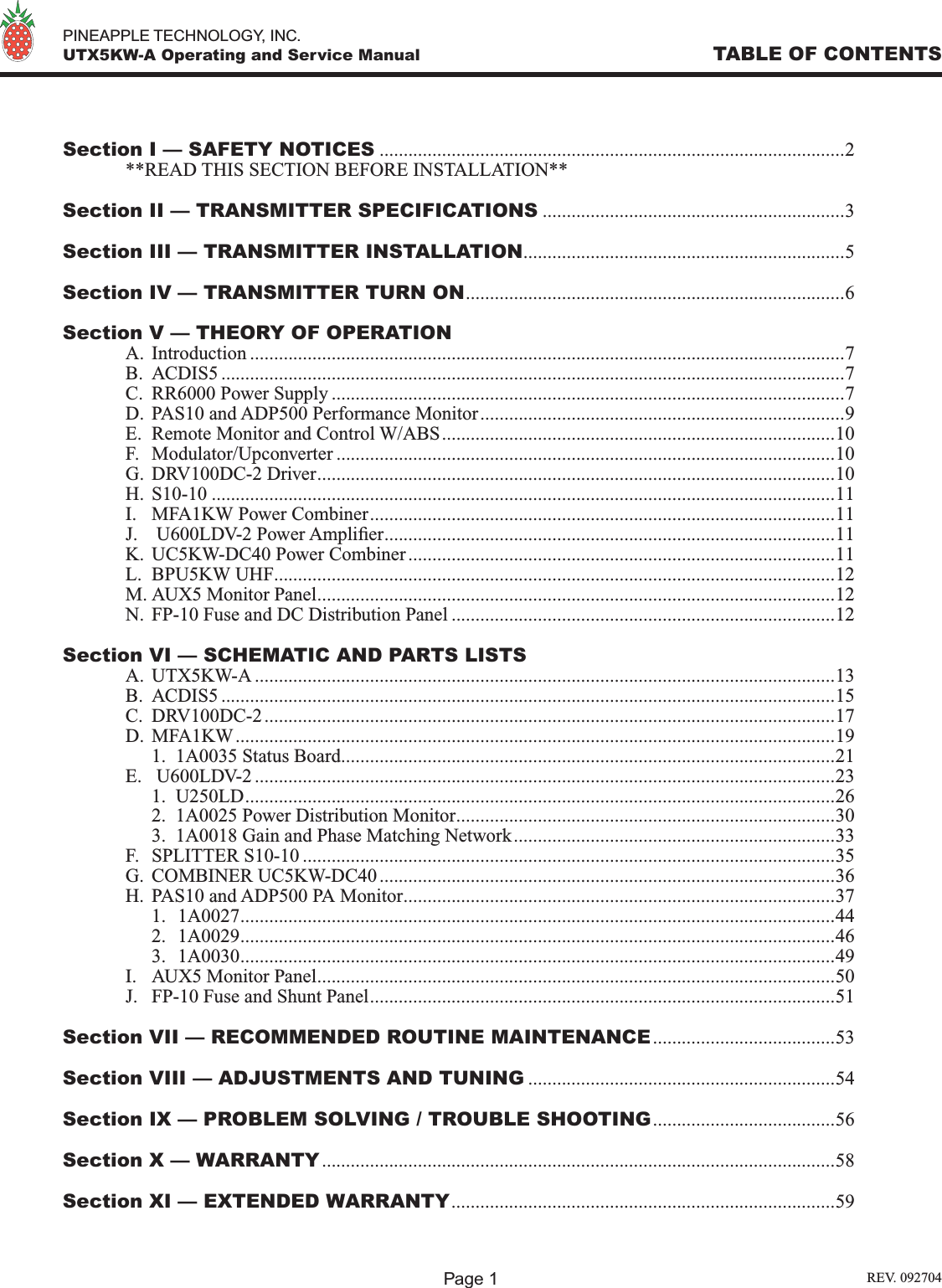
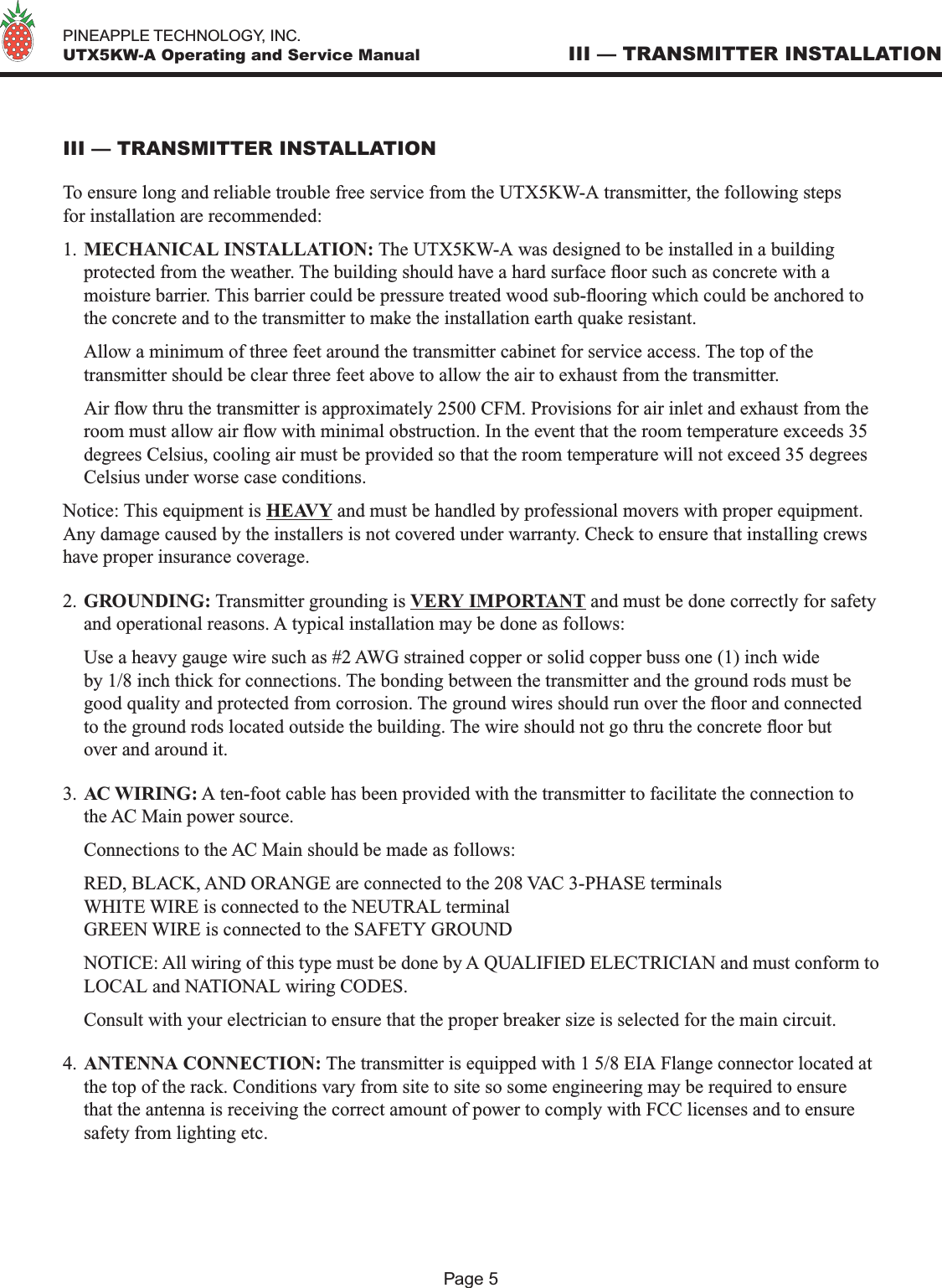
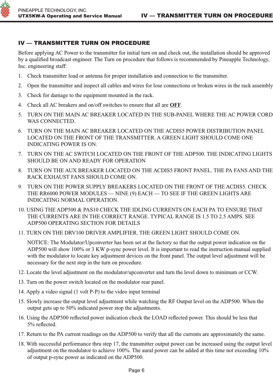
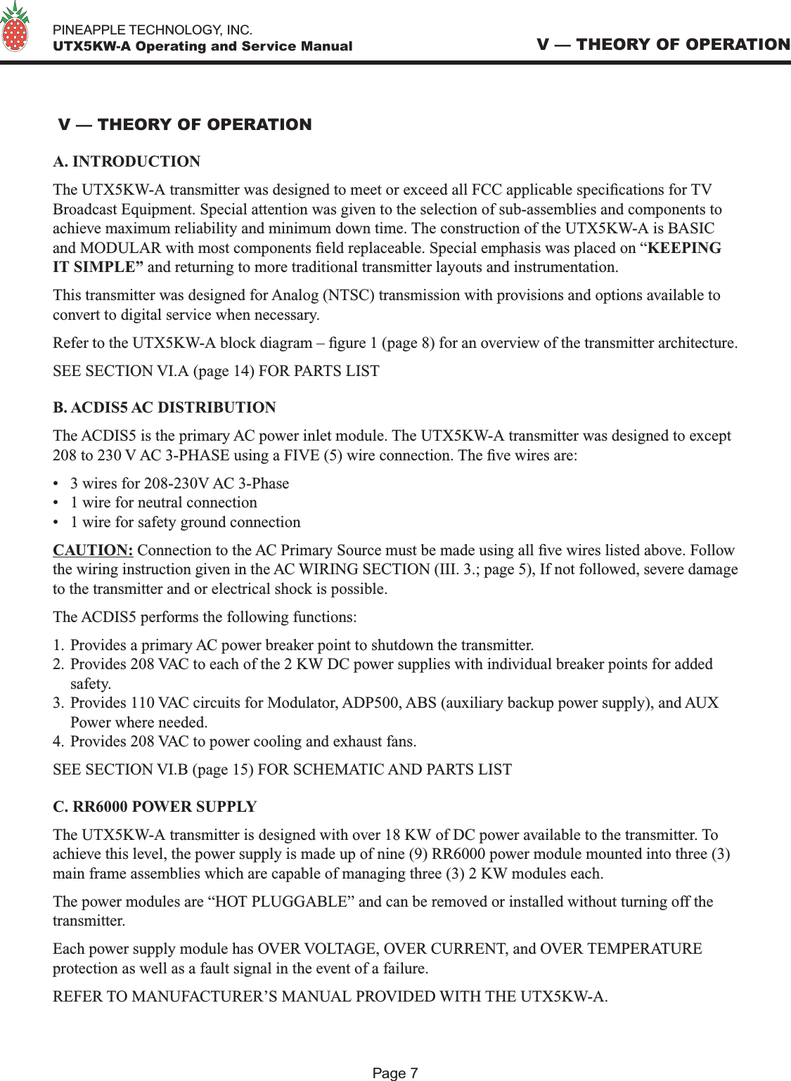
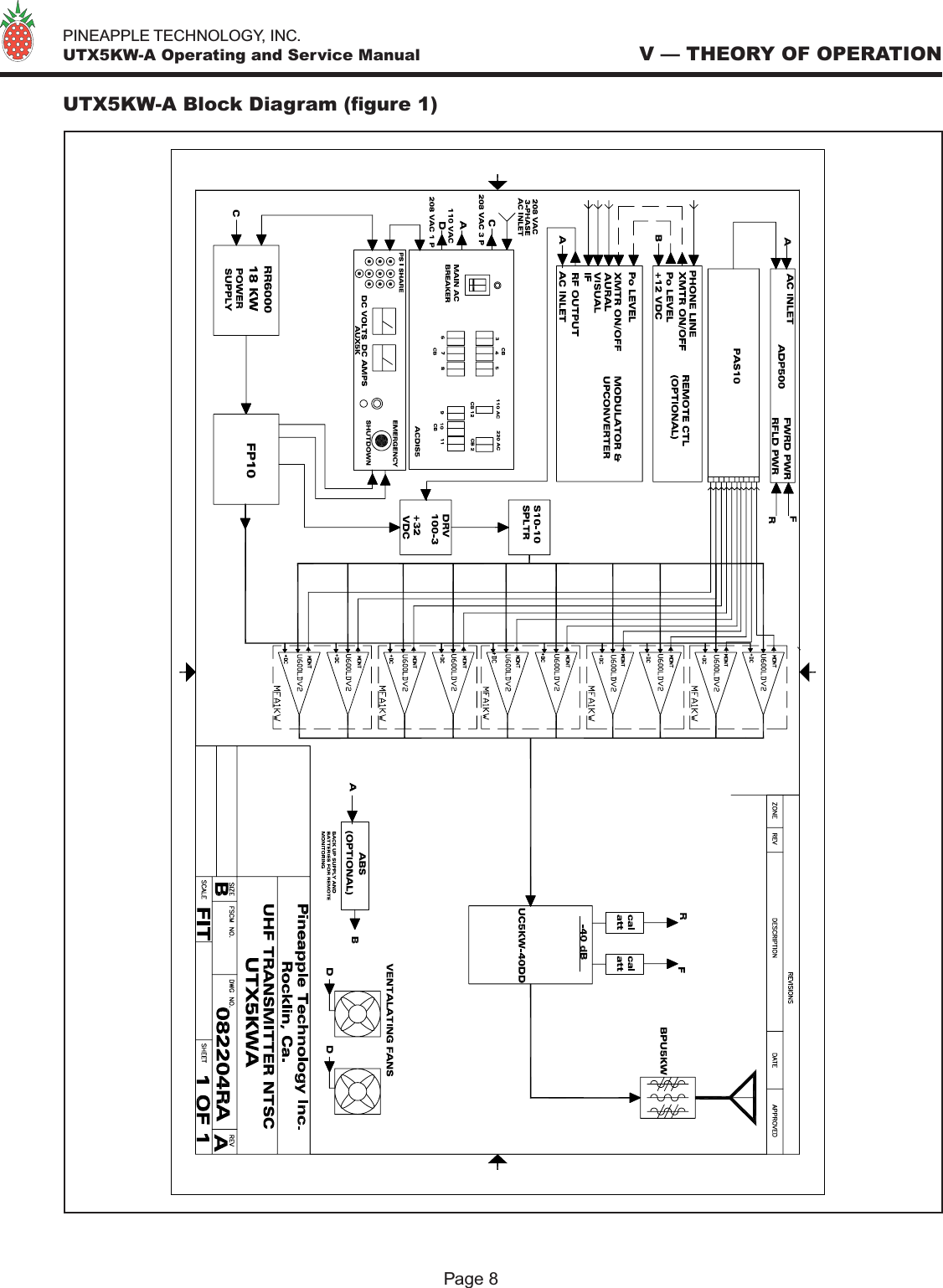
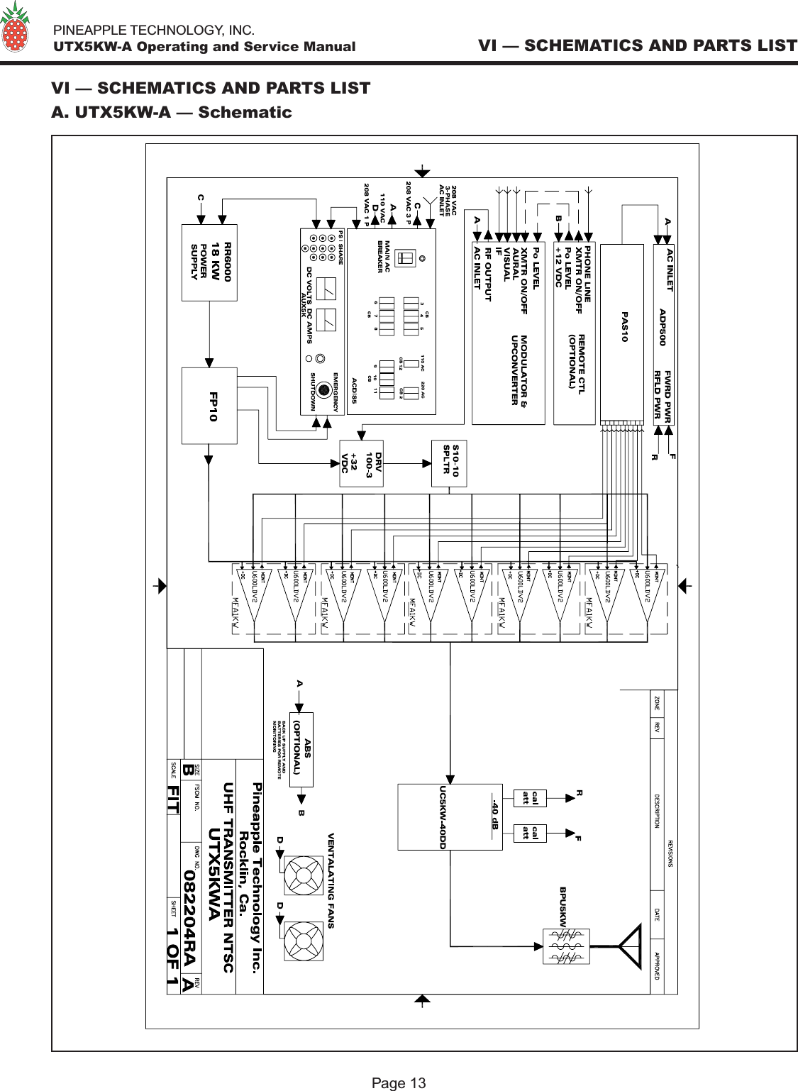
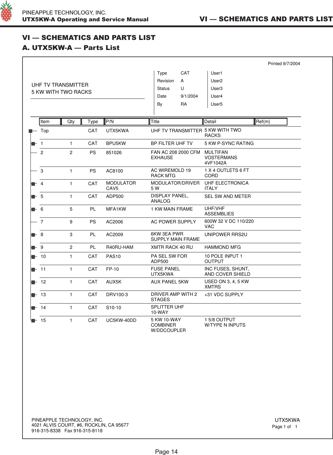
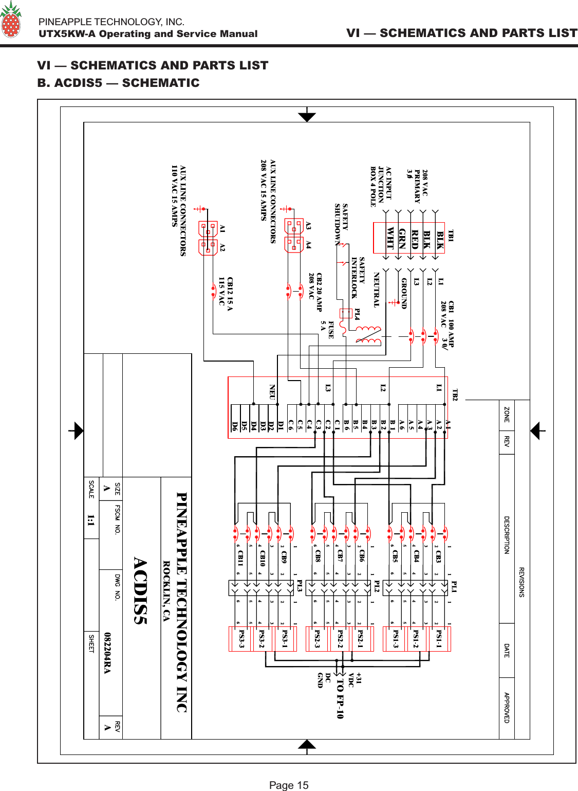
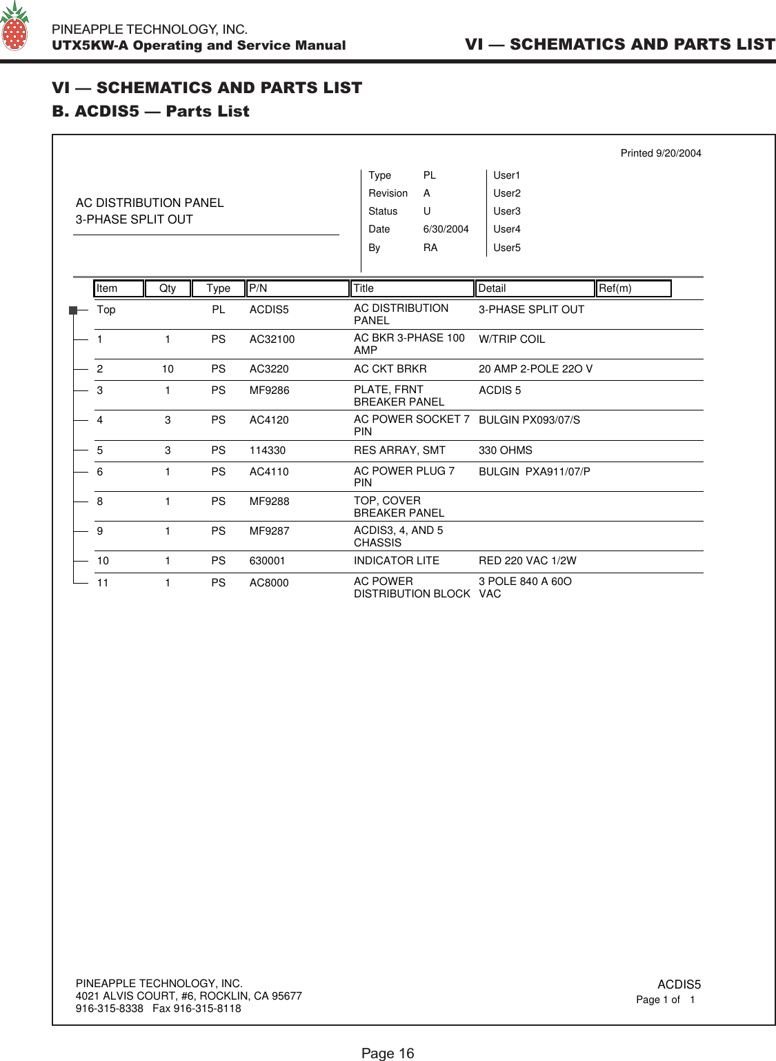
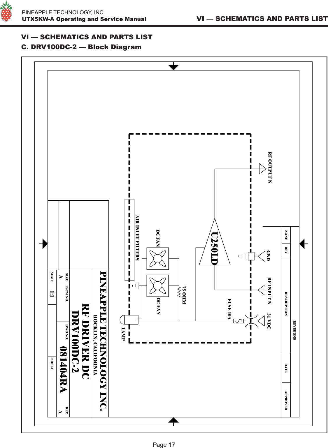
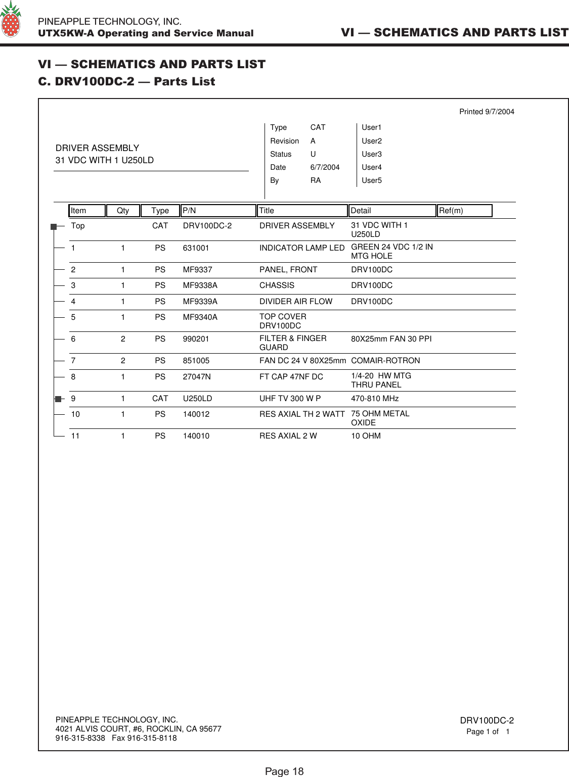
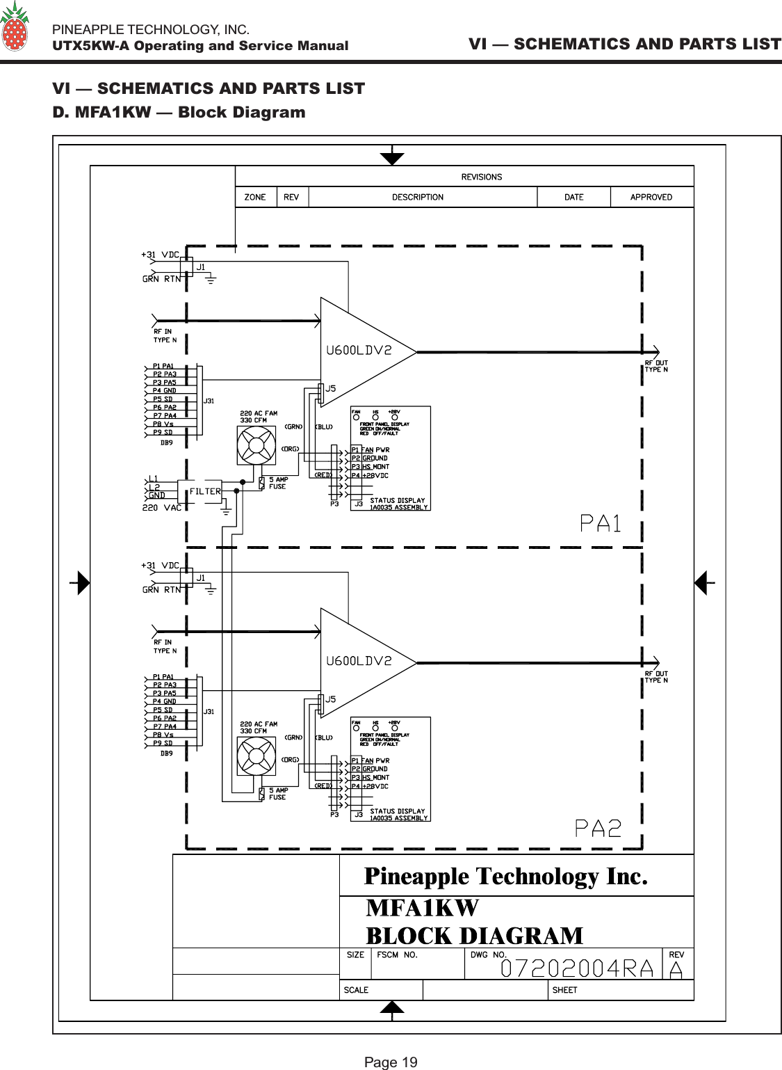
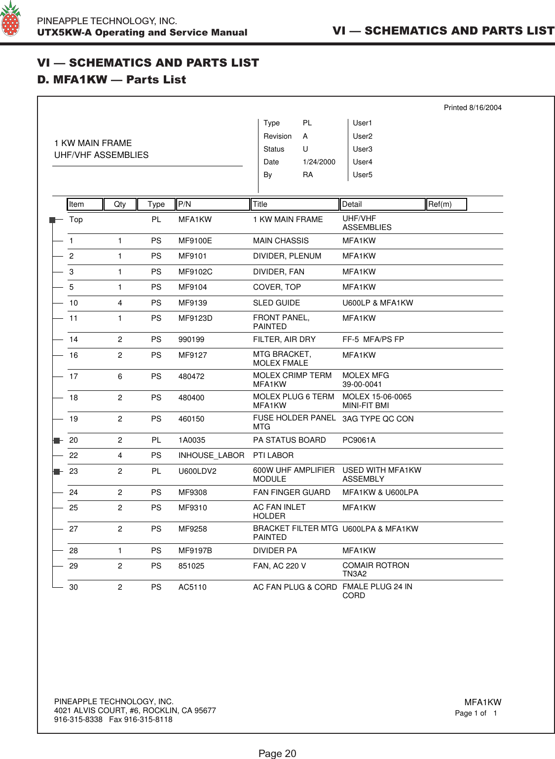
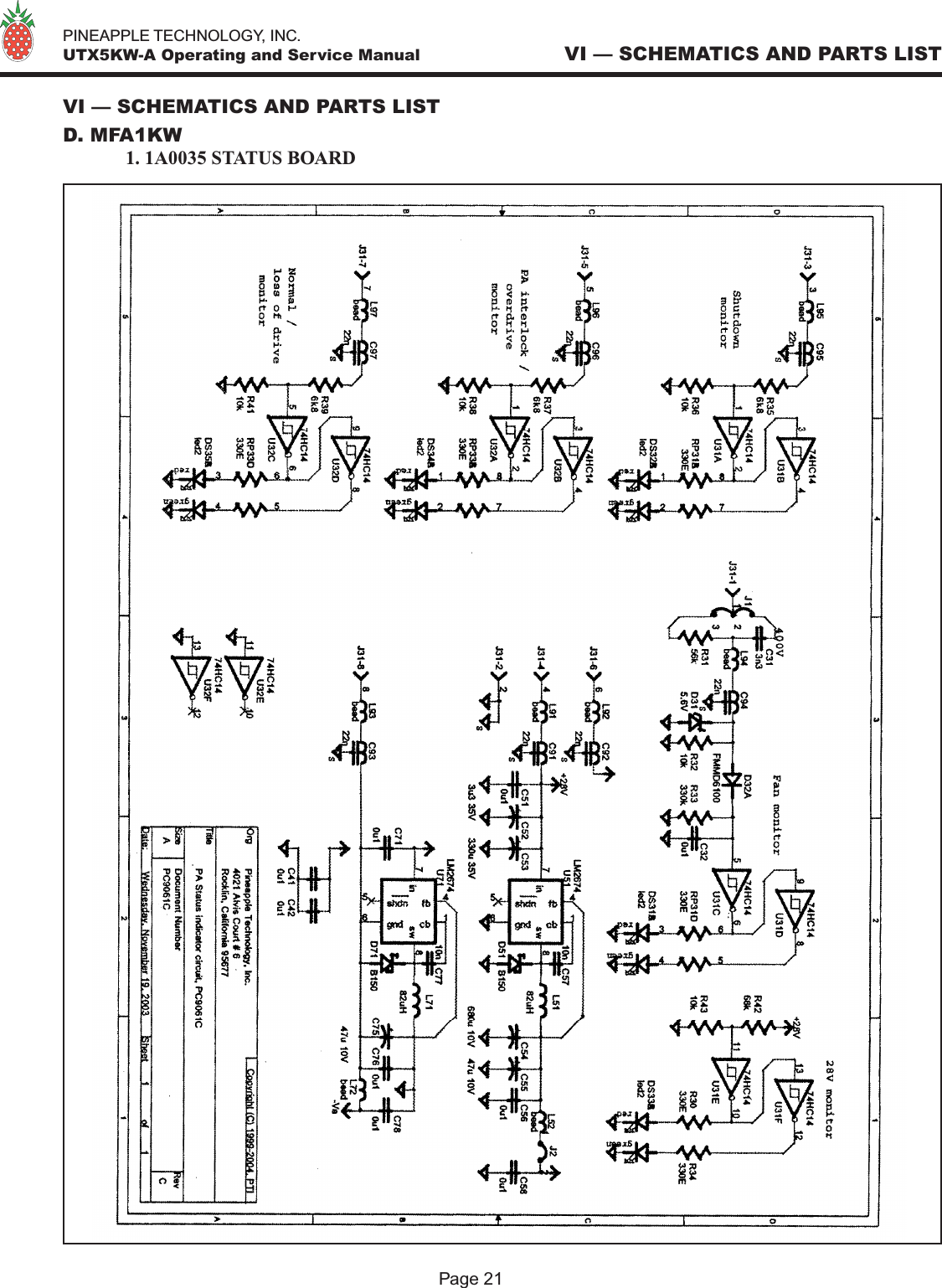
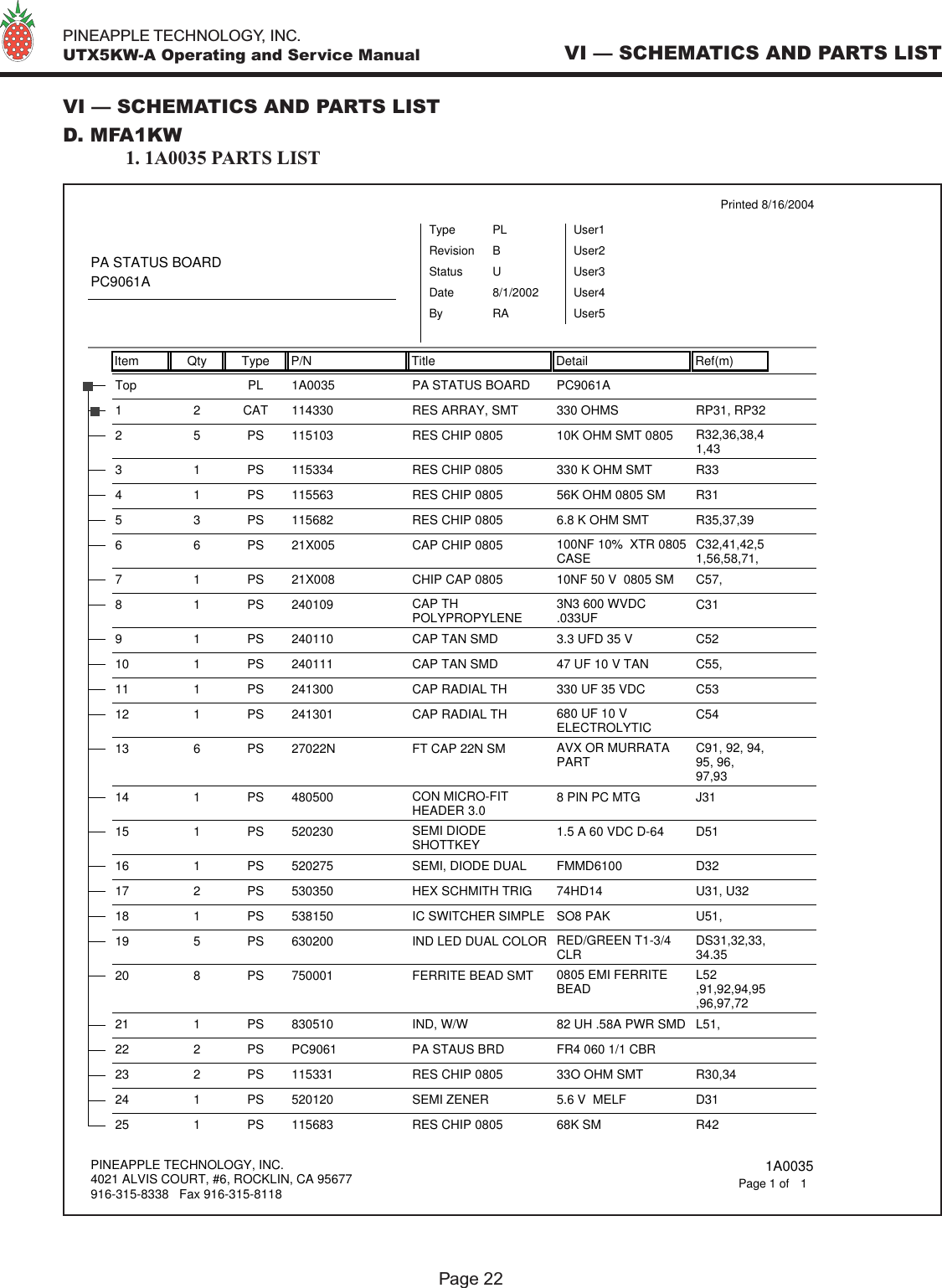
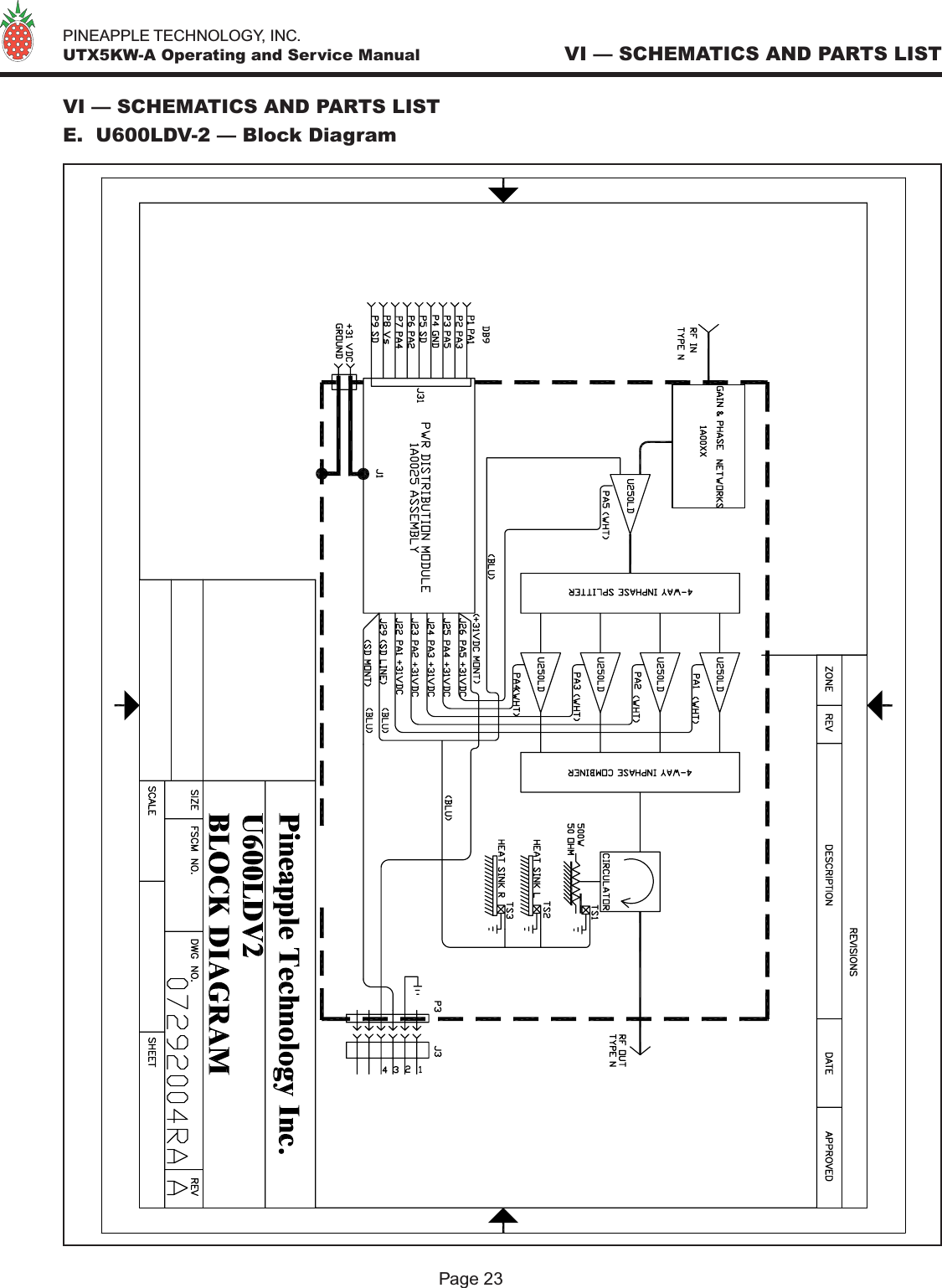
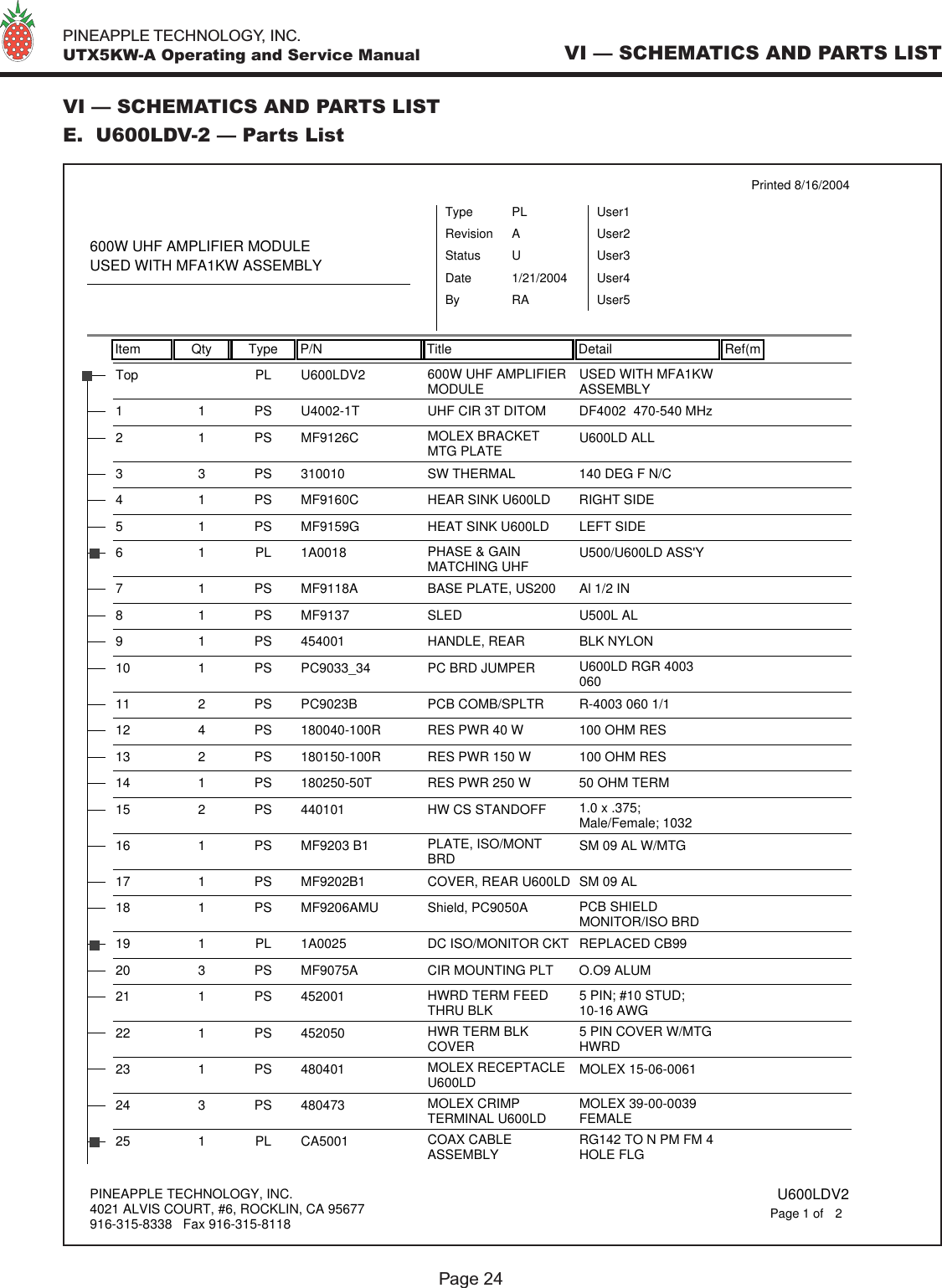
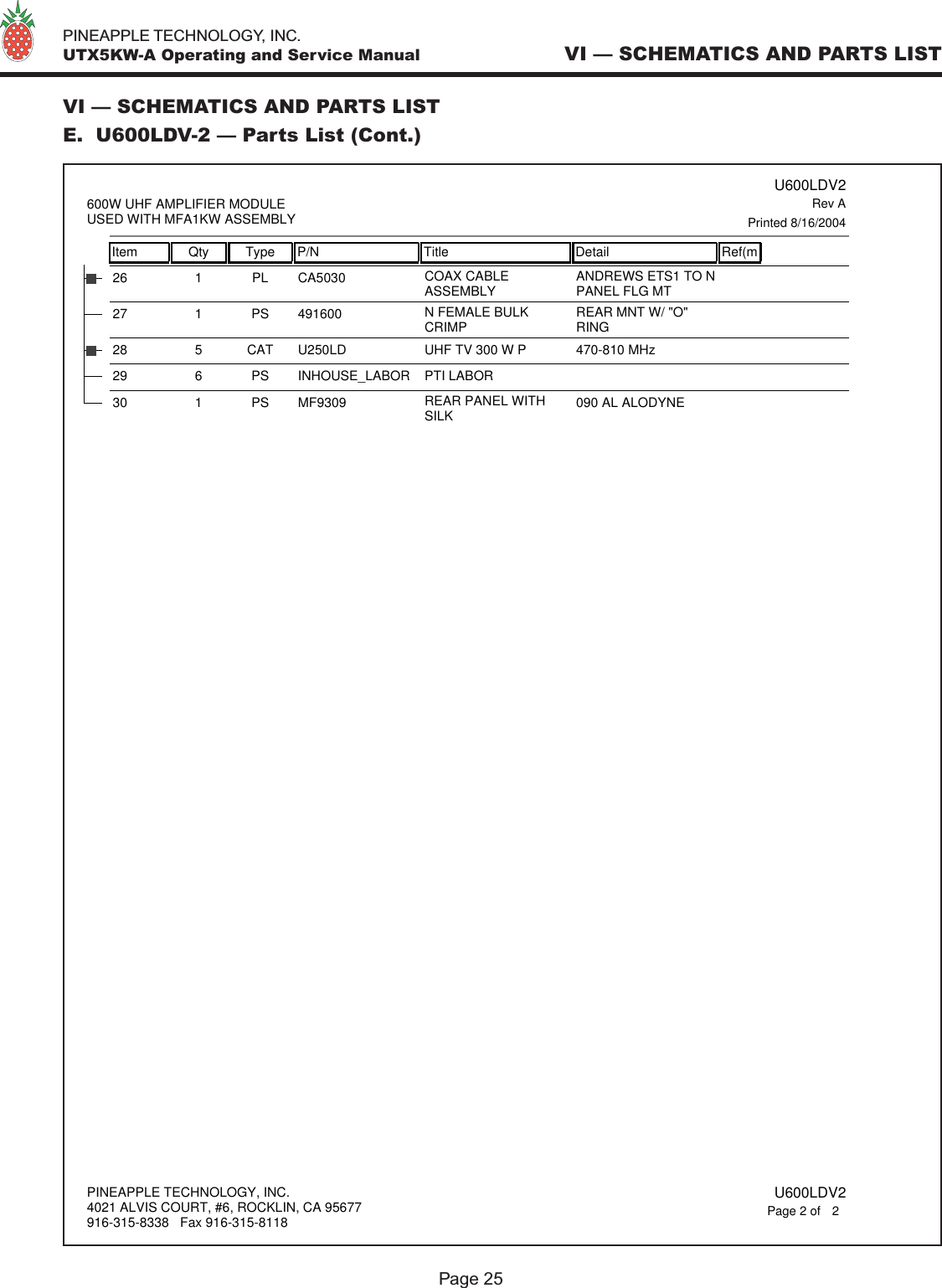
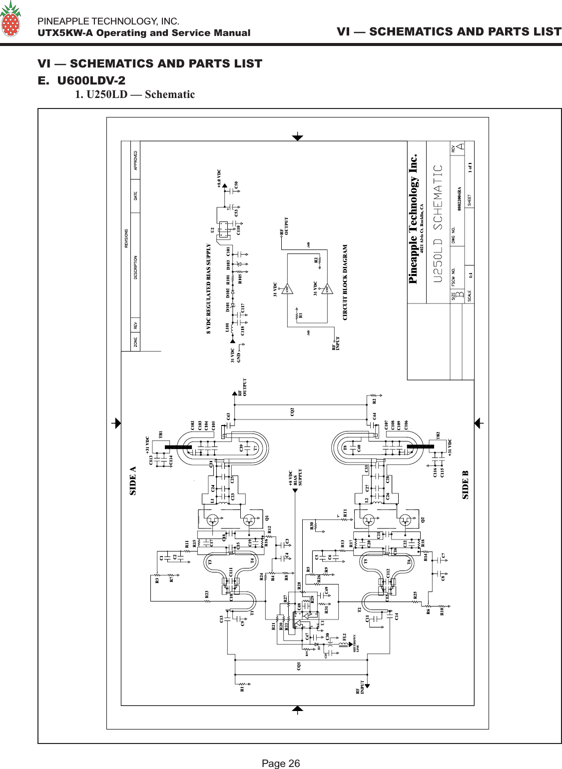
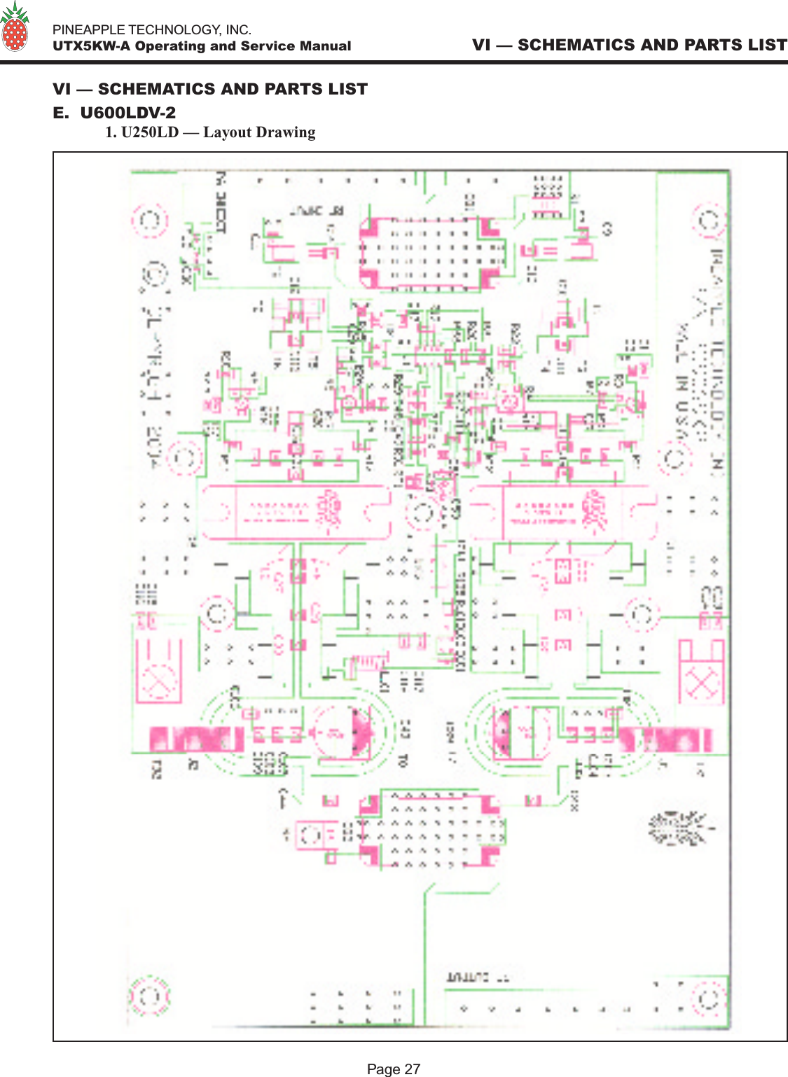
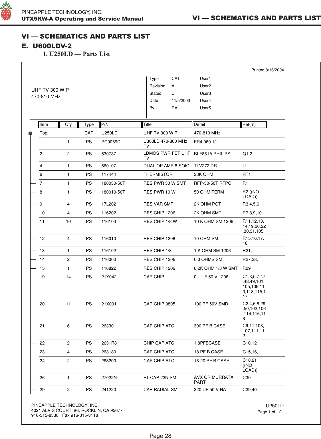
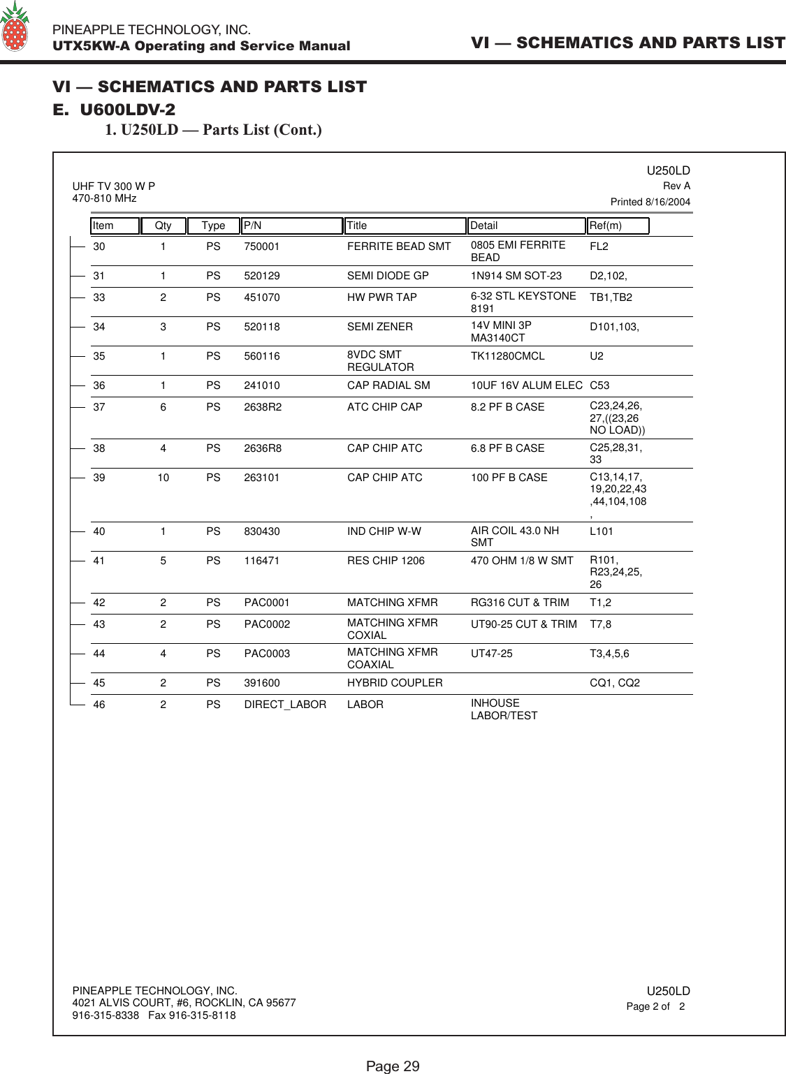
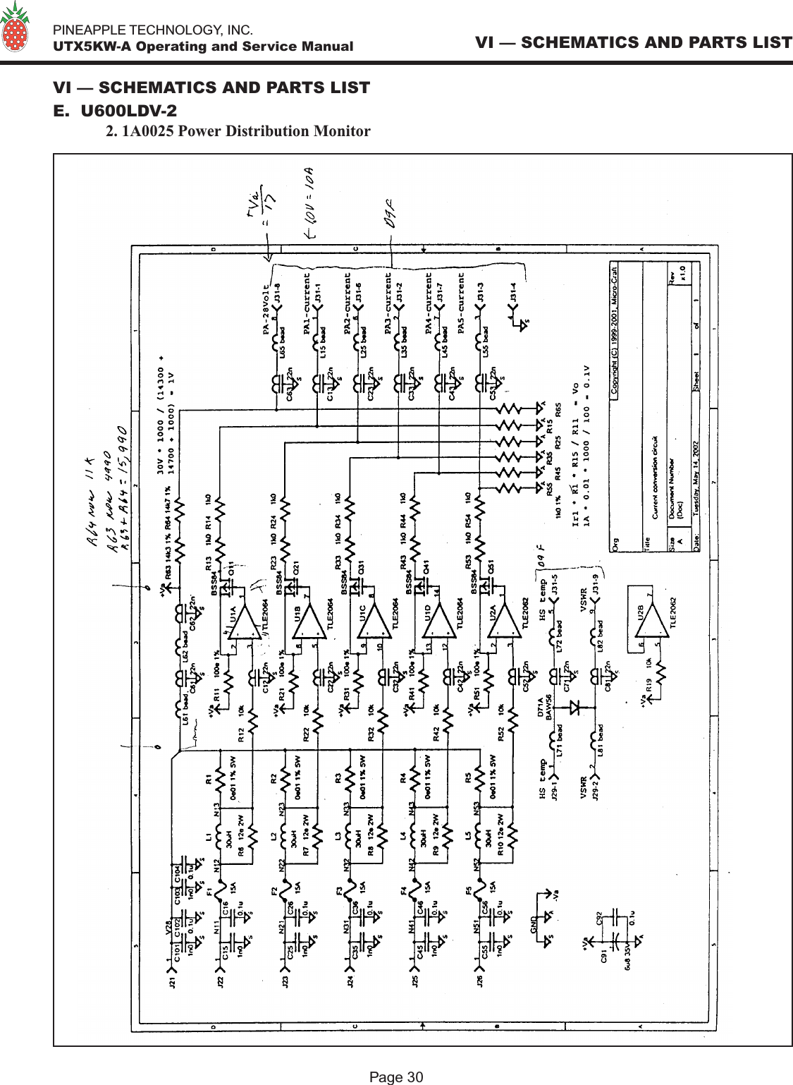
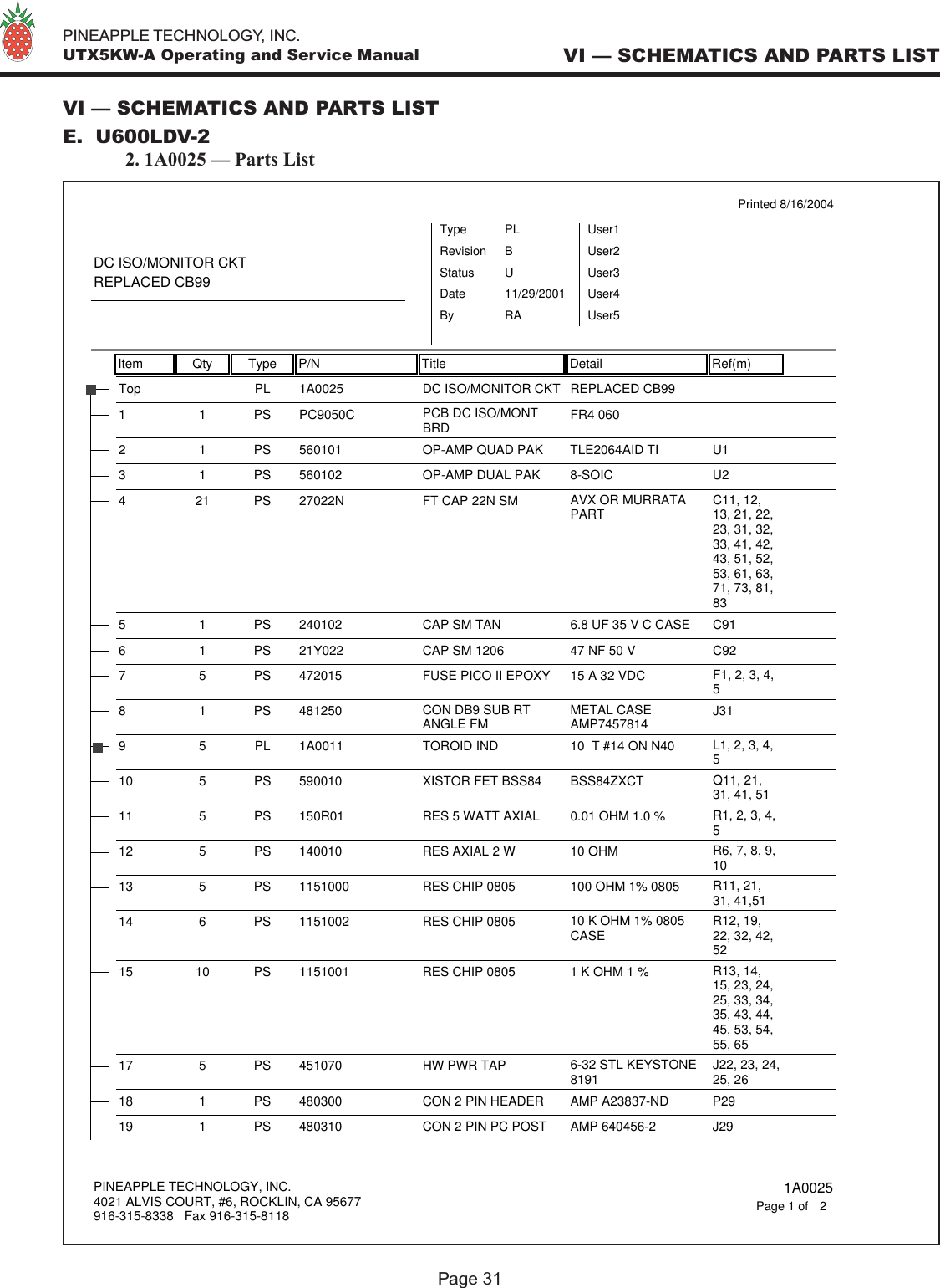
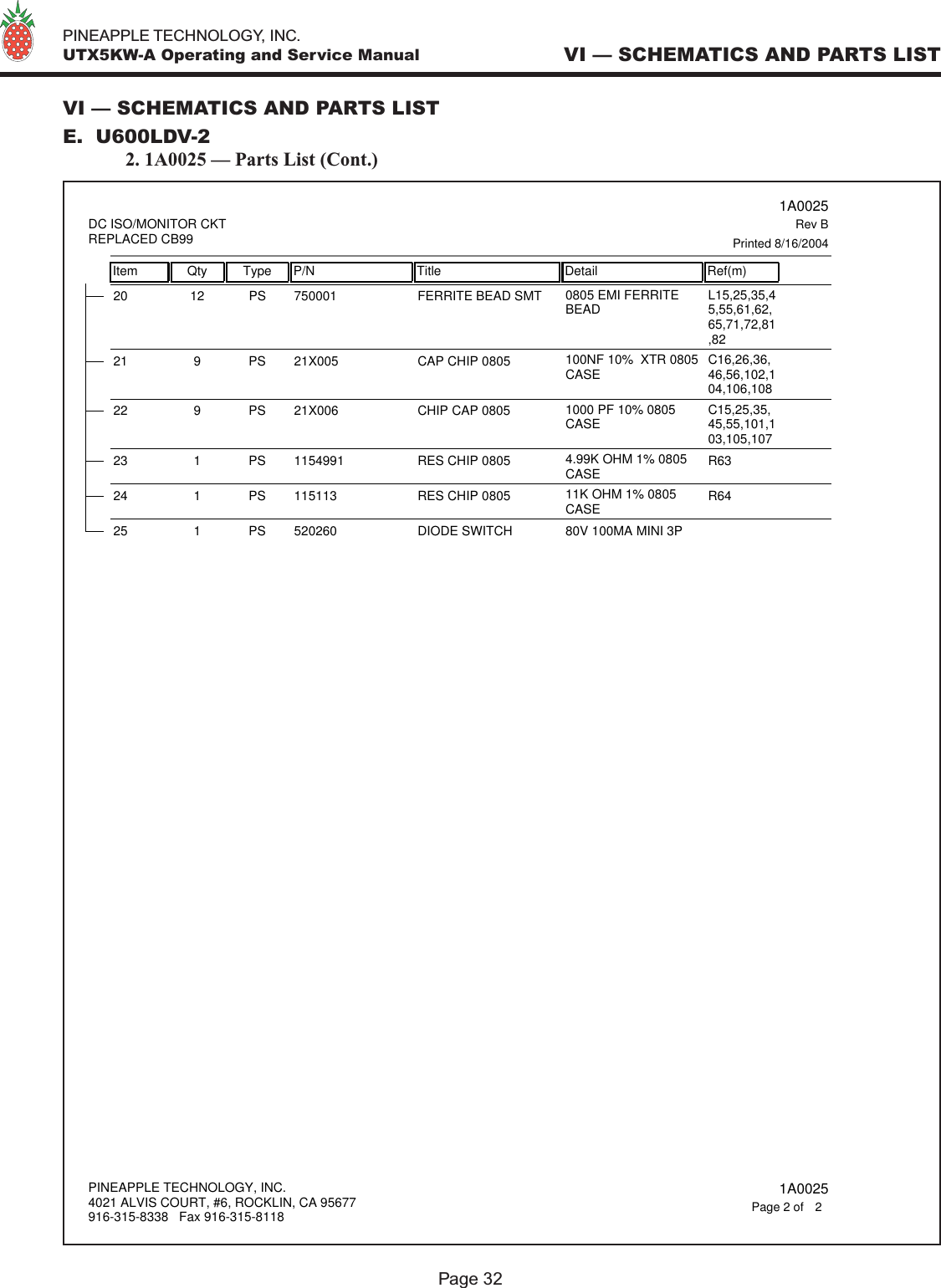
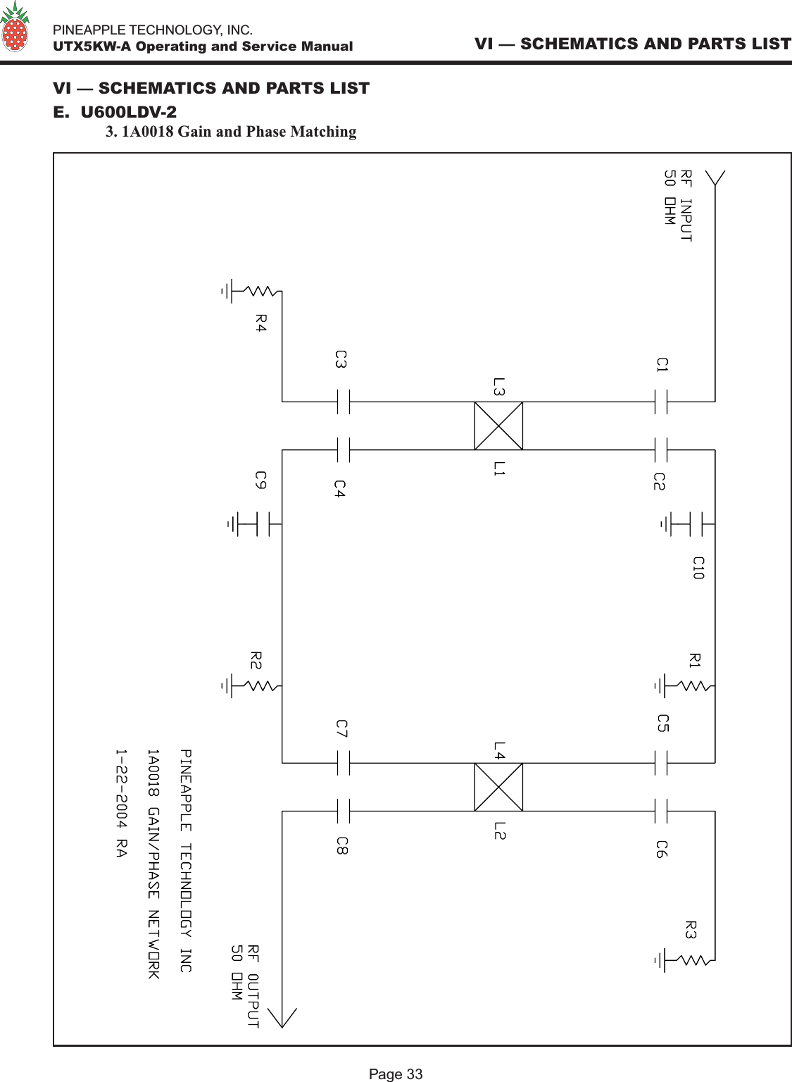
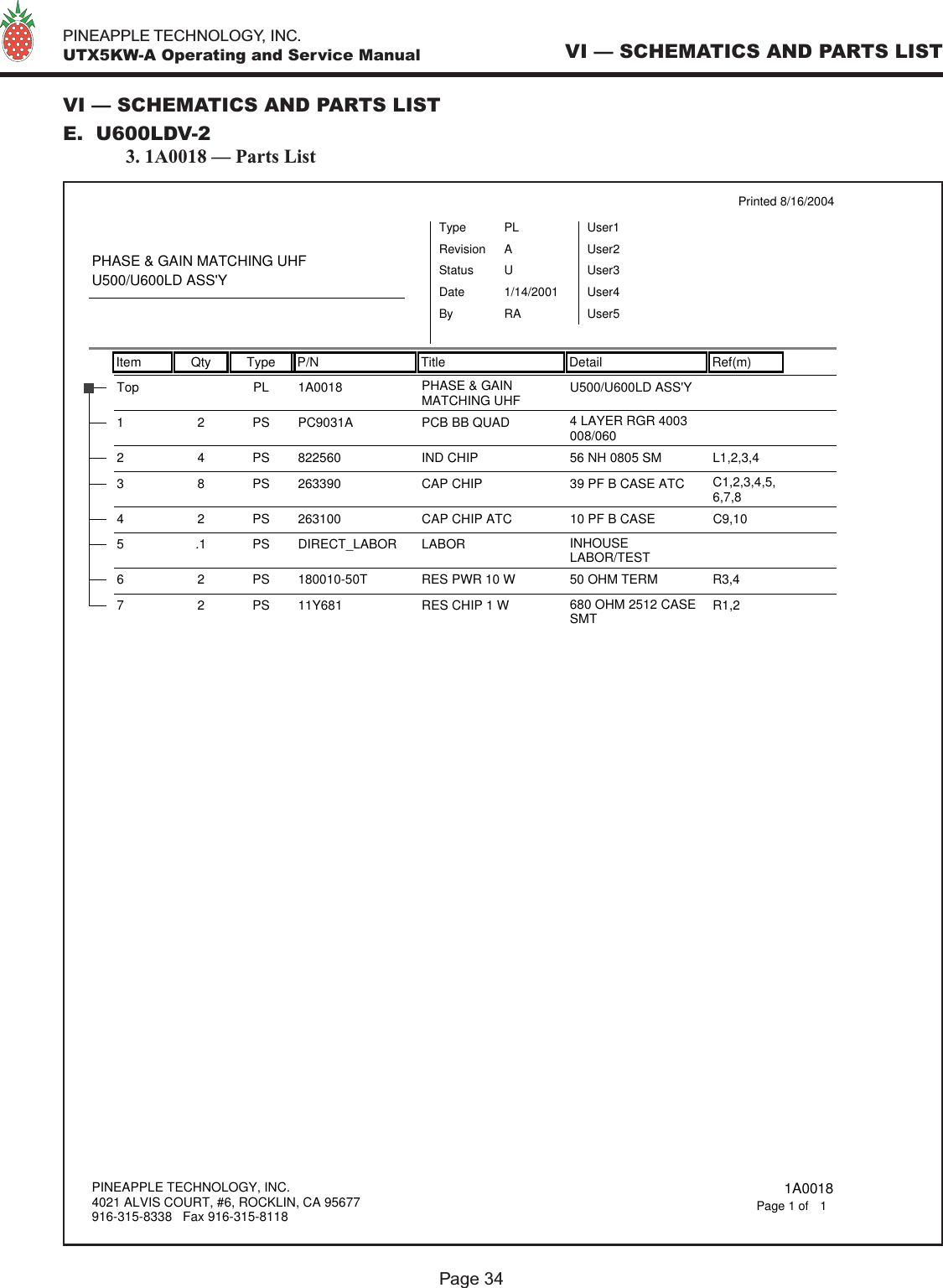
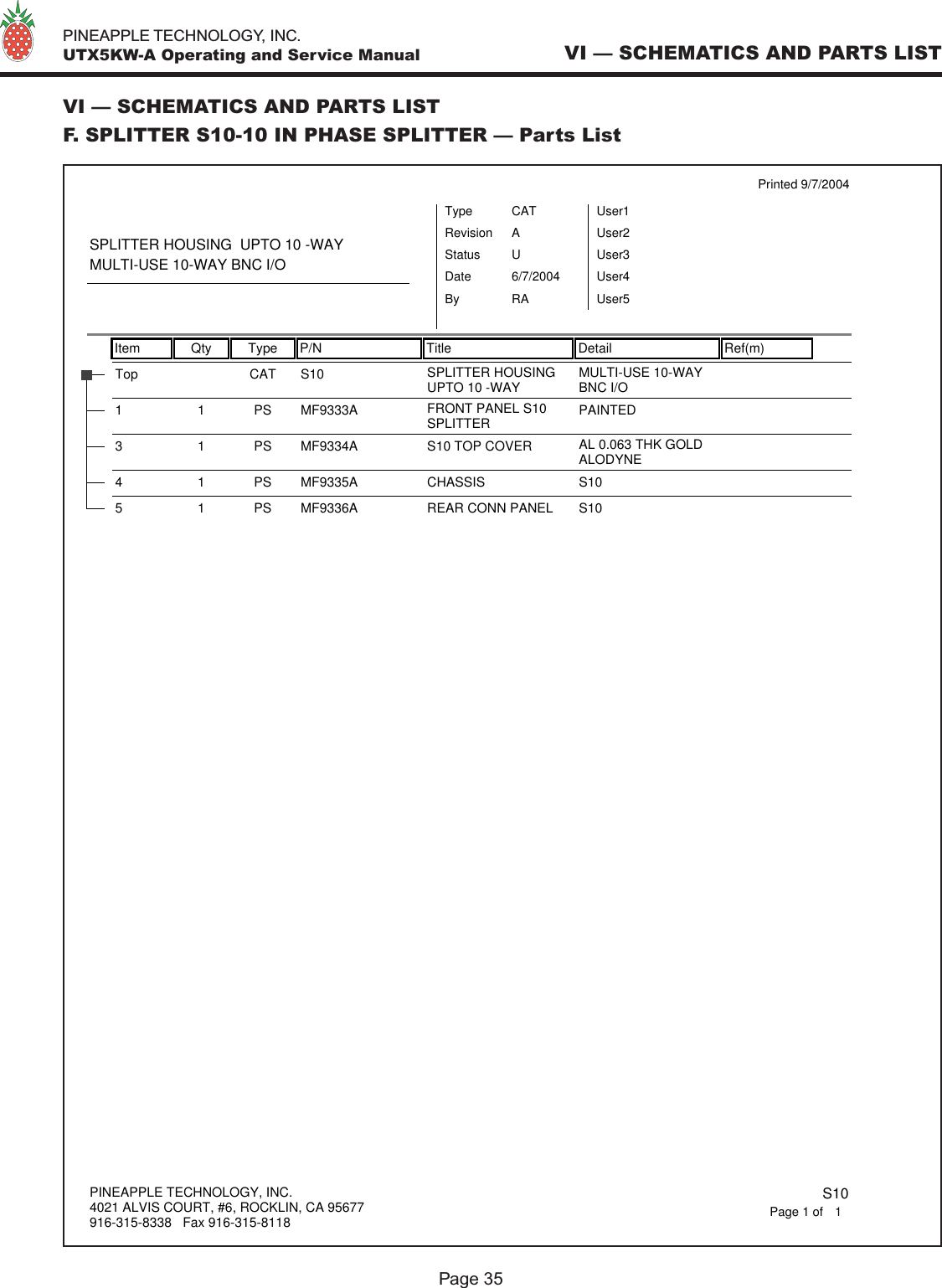
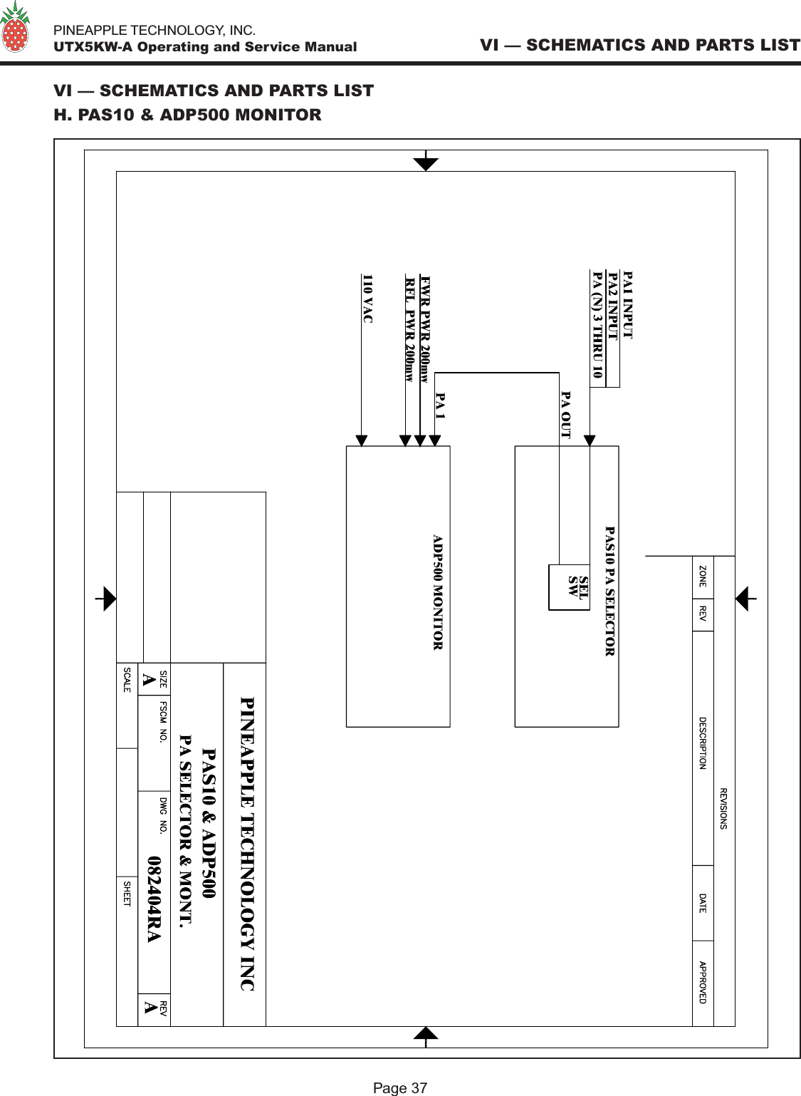
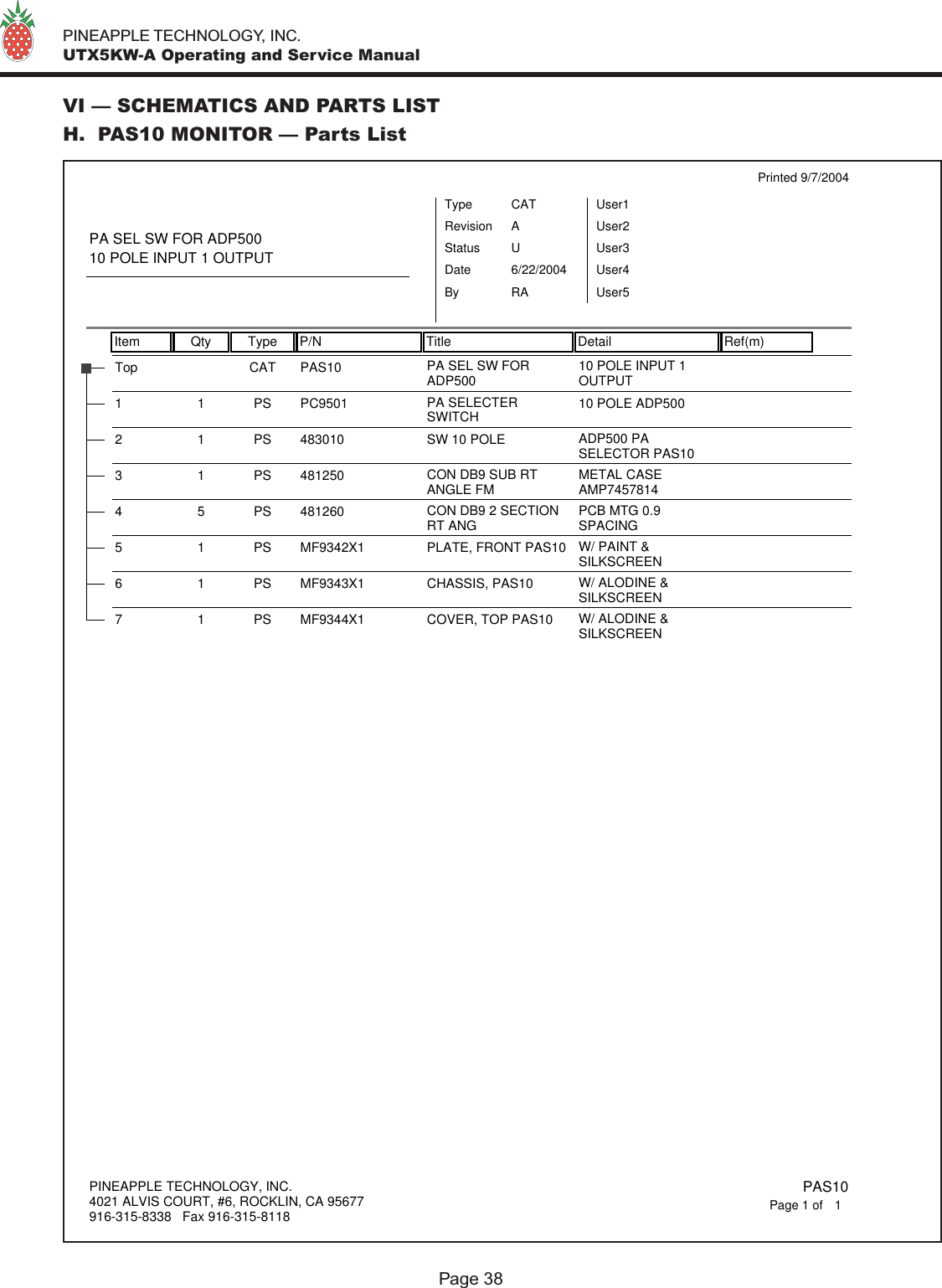
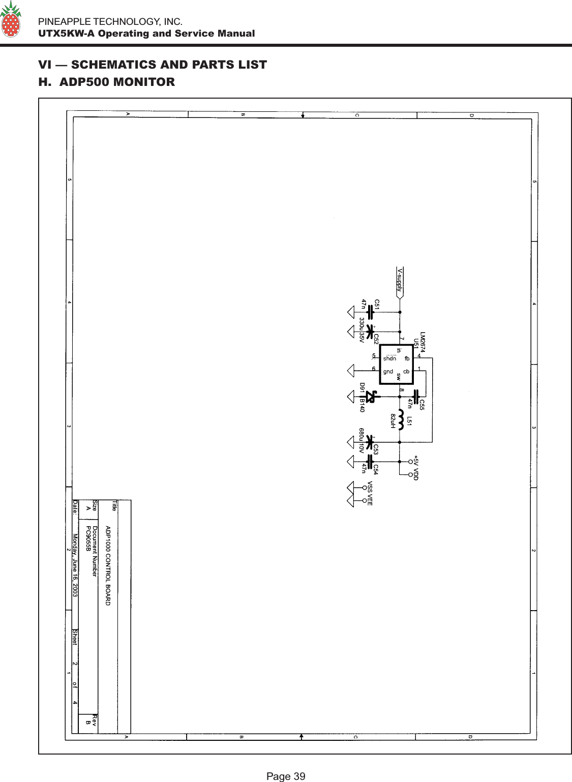
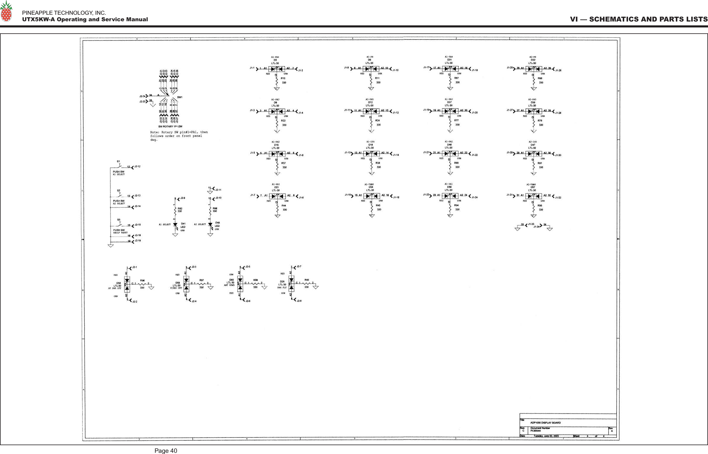
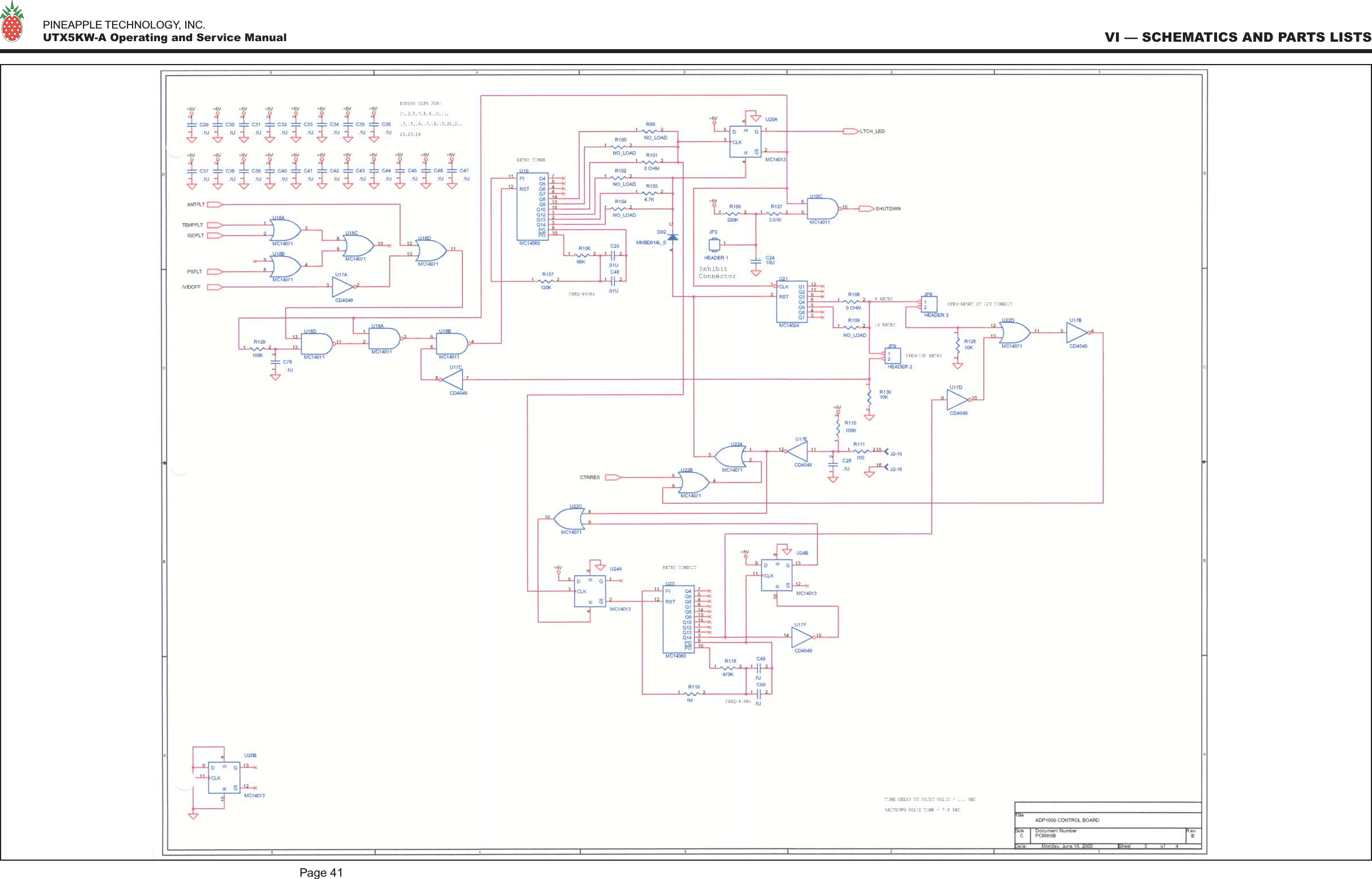
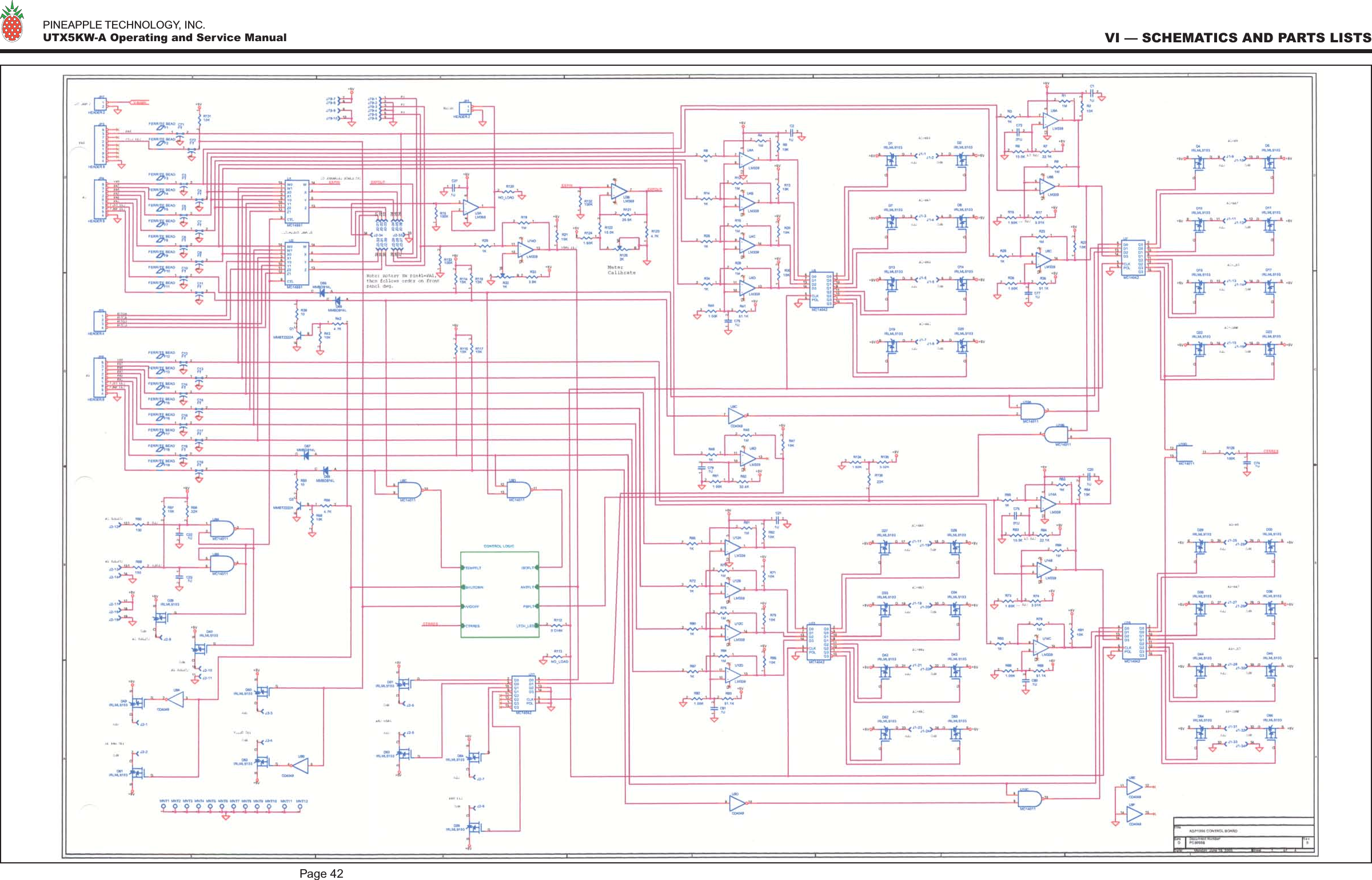
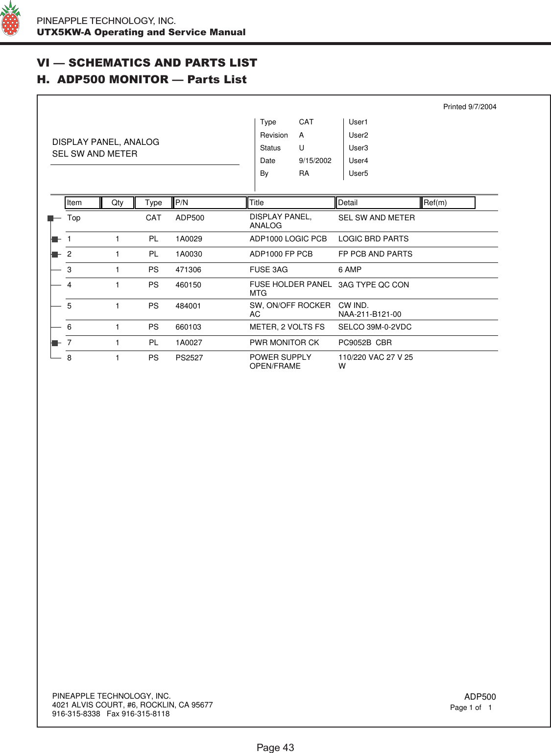
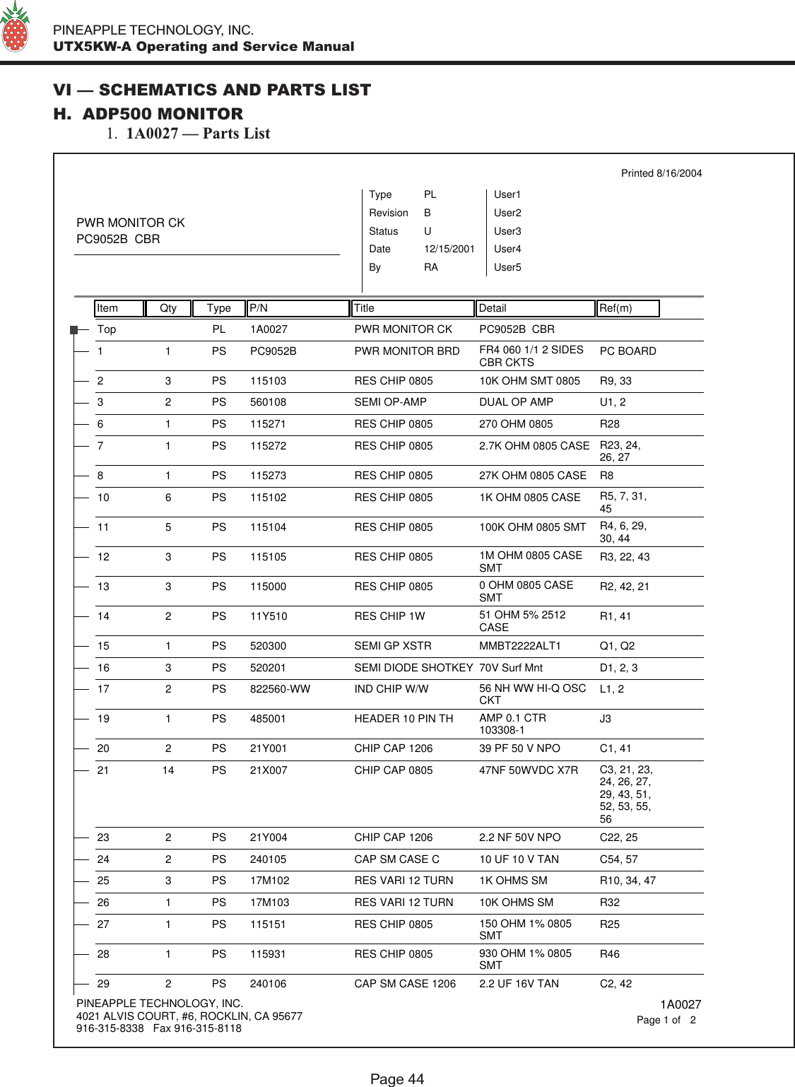
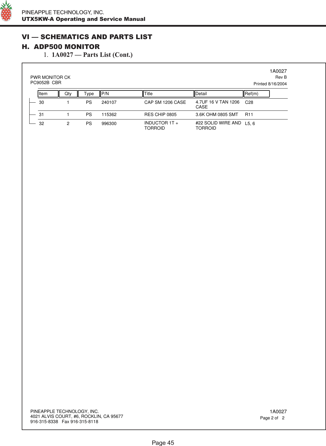
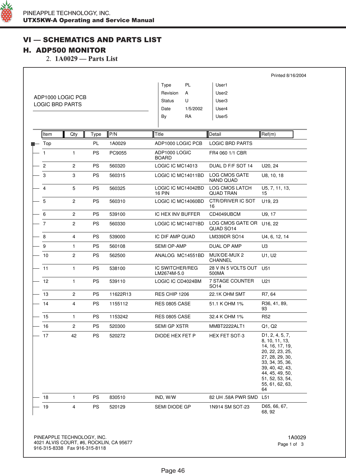
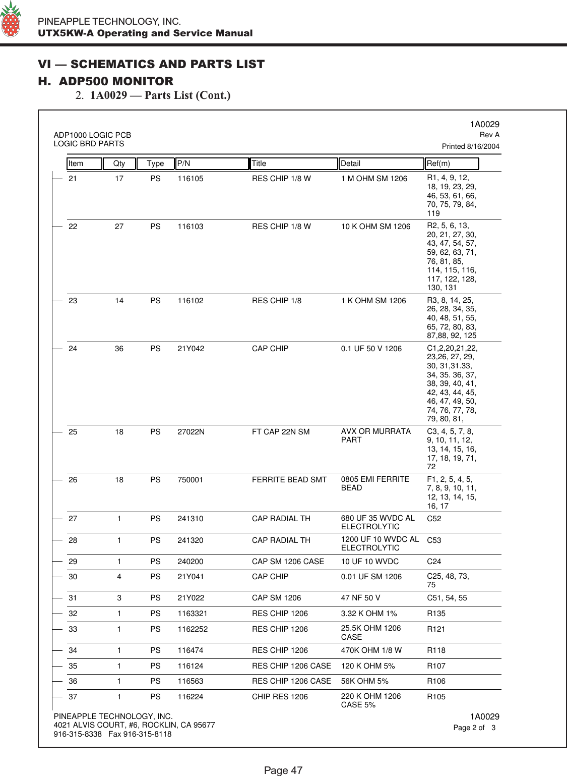
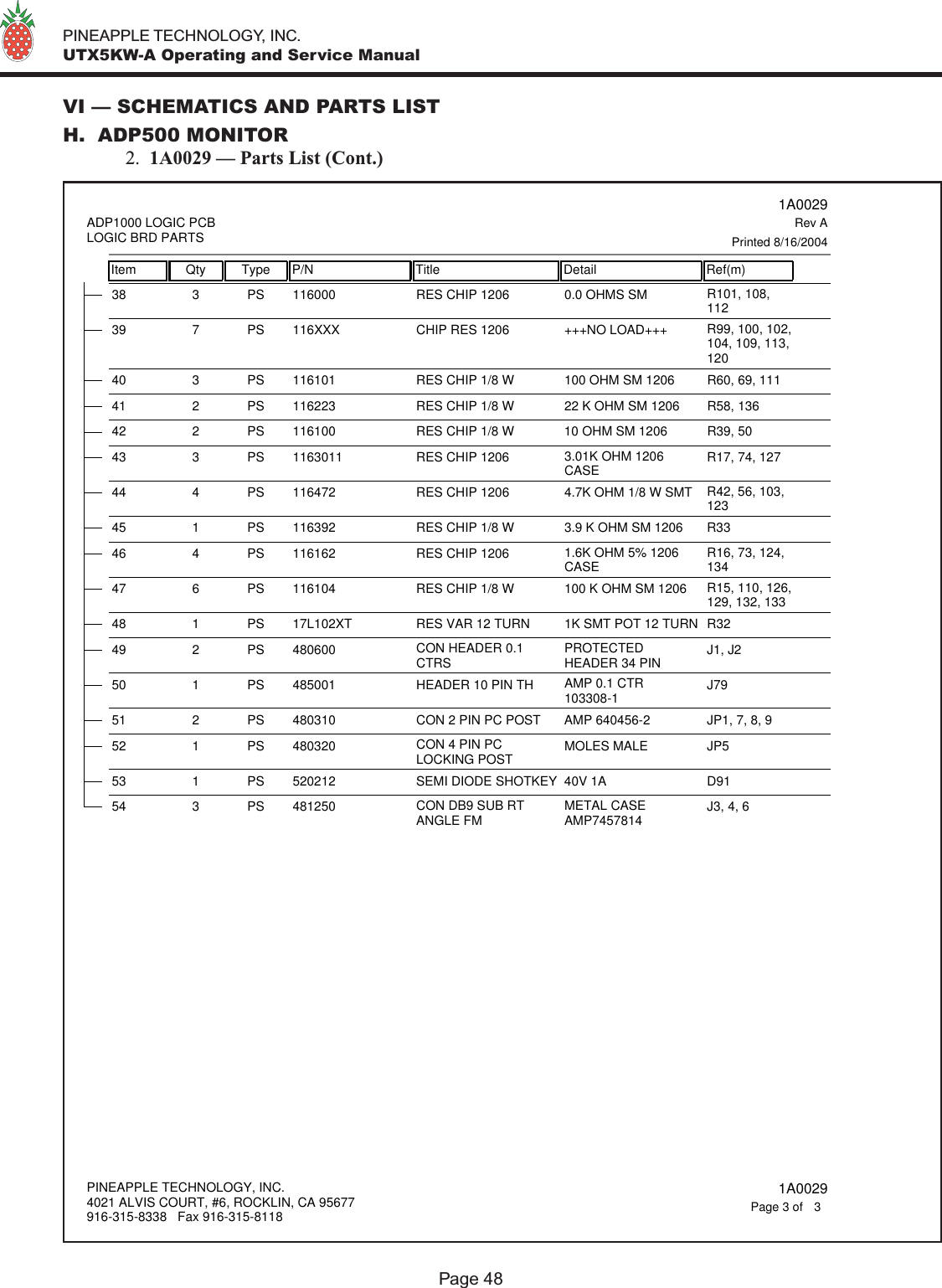
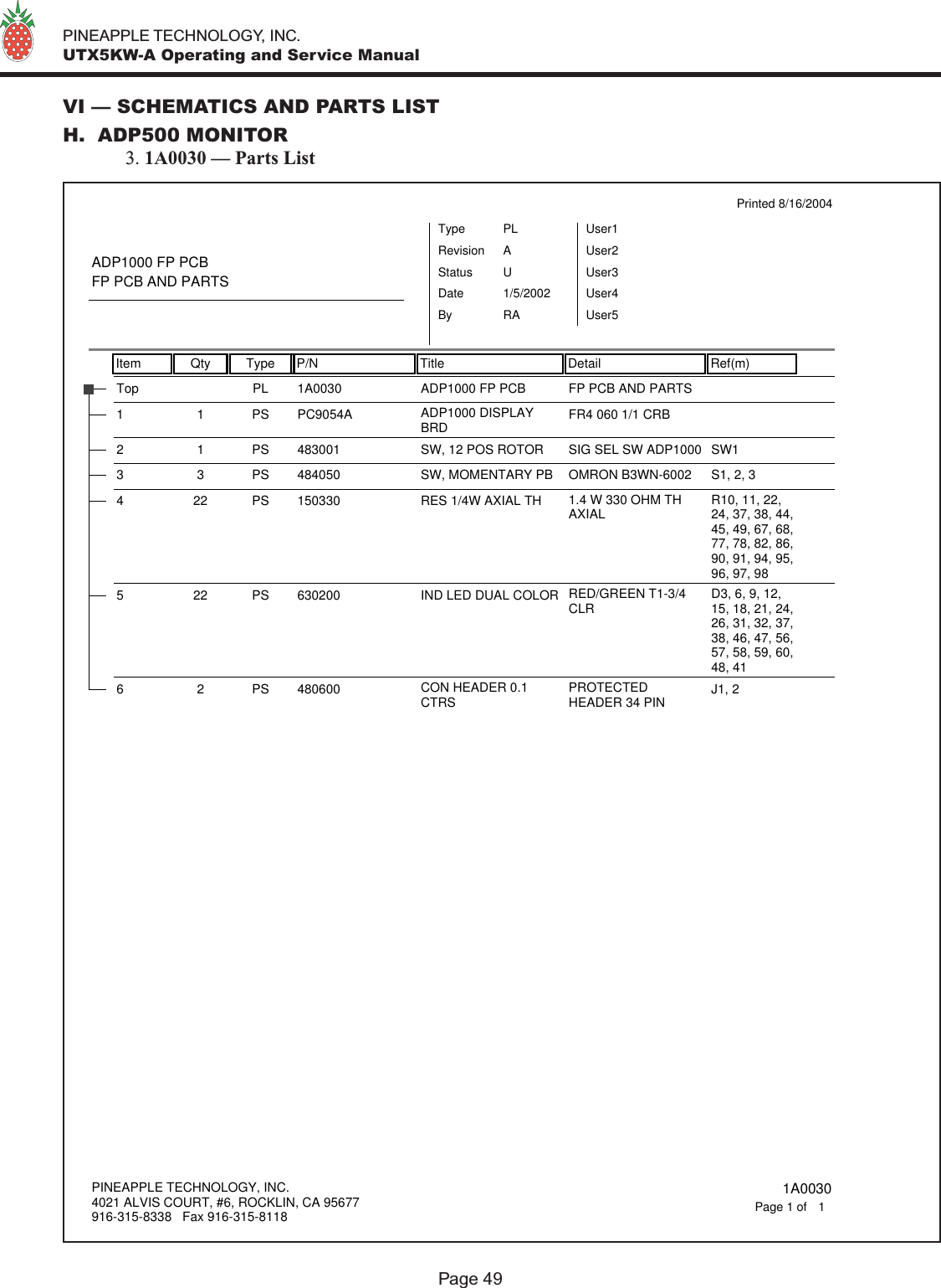
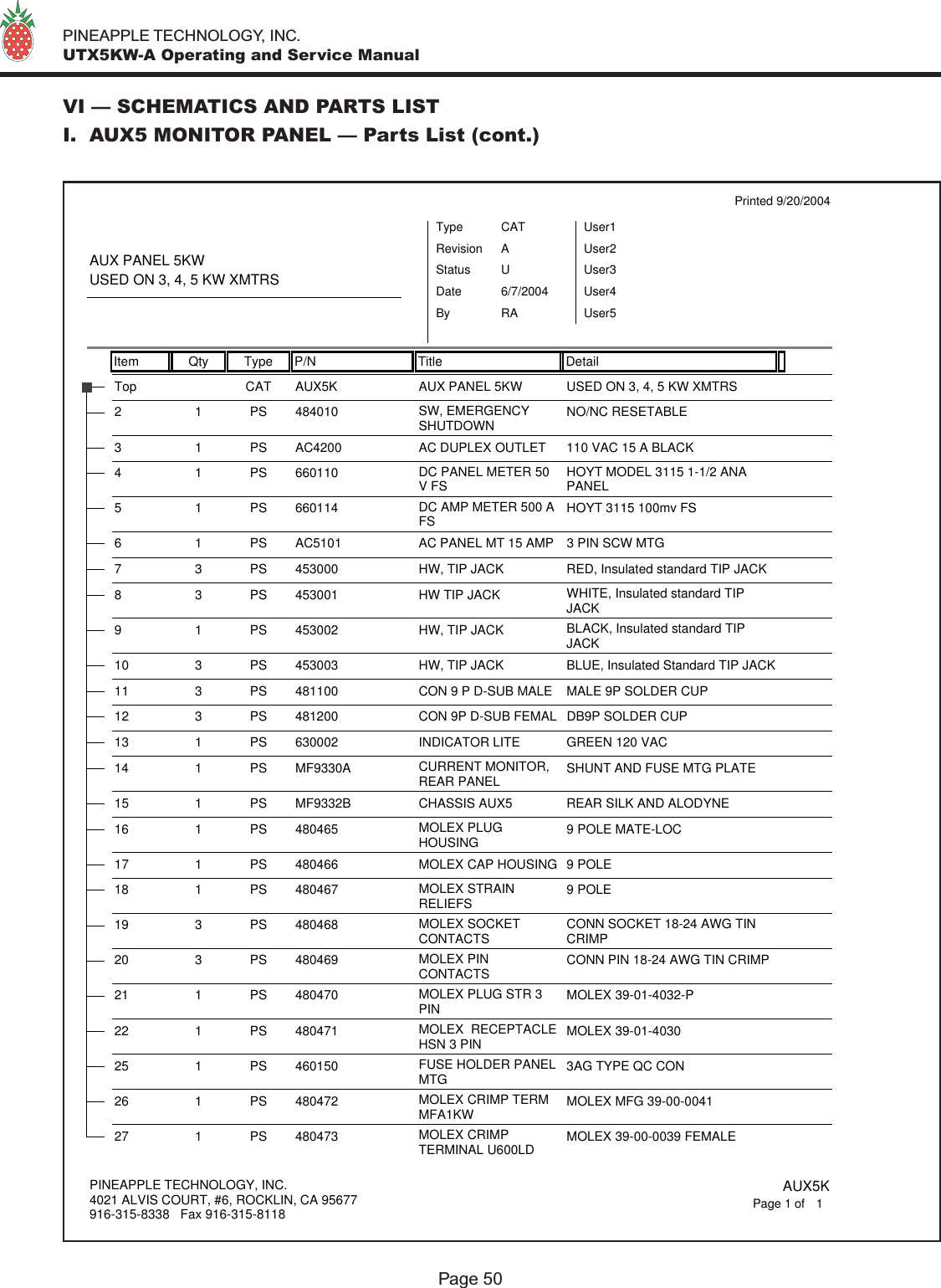
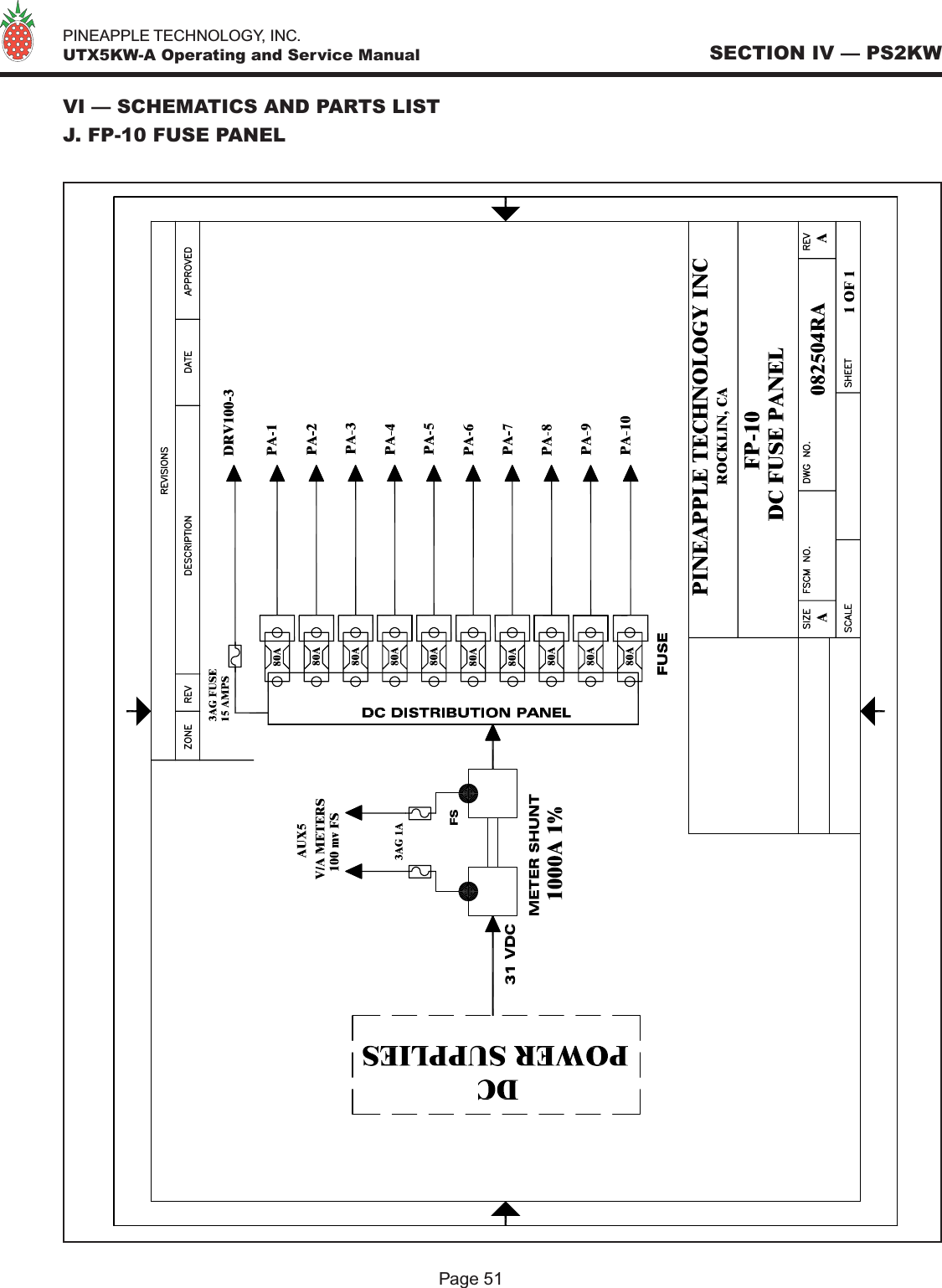
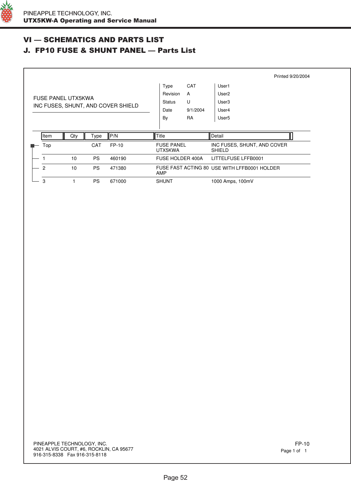
Technical manual containing parts lists and tune up info and schematics

U T X 5 K W - AINSTRUCTION MANUAL           SN:              PINEAPPLE TECHNOLOGY, INC.
  PINEAPPLE TECHNOLOGY, INC.  UTX5KW-A Operating and Service Manual TABLE OF CONTENTSSection I — SAFETY NOTICES .................................................................................................2  **READ THIS SECTION BEFORE INSTALLATION**Section II — TRANSMITTER SPECIFICATIONS ...............................................................3Section III — TRANSMITTER INSTALLATION...................................................................5Section IV — TRANSMITTER TURN ON...............................................................................6Section V — THEORY OF OPERATION  A.  Introduction ............................................................................................................................7  B.  ACDIS5 ..................................................................................................................................7  C.  RR6000 Power Supply ...........................................................................................................7  D.  PAS10 and ADP500 Performance Monitor............................................................................9  E.  Remote Monitor and Control W/ABS..................................................................................10  F.  Modulator/Upconverter ........................................................................................................10  G.  DRV100DC-2 Driver............................................................................................................10  H.  S10-10 ..................................................................................................................................11  I.  MFA1KW Power Combiner.................................................................................................11  J.   U600LDV-2 Power Amplier..............................................................................................11  K.  UC5KW-DC40 Power Combiner.........................................................................................11  L.  BPU5KW UHF.....................................................................................................................12  M. AUX5 Monitor Panel............................................................................................................12  N.  FP-10 Fuse and DC Distribution Panel ................................................................................12Section VI — SCHEMATIC AND PARTS LISTS  A.  UTX5KW-A .........................................................................................................................13  B.  ACDIS5 ................................................................................................................................15  C.  DRV100DC-2.......................................................................................................................17  D.  MFA1KW.............................................................................................................................19    1.  1A0035 Status Board.......................................................................................................21  E.   U600LDV-2 .........................................................................................................................23    1.  U250LD...........................................................................................................................26    2.  1A0025 Power Distribution Monitor...............................................................................30    3.  1A0018 Gain and Phase Matching Network...................................................................33  F.  SPLITTER S10-10 ...............................................................................................................35  G.  COMBINER UC5KW-DC40 ...............................................................................................36  H.  PAS10 and ADP500 PA Monitor..........................................................................................37    1.  1A0027............................................................................................................................44    2.  1A0029............................................................................................................................46    3.  1A0030............................................................................................................................49  I.  AUX5 Monitor Panel............................................................................................................50  J.  FP-10 Fuse and Shunt Panel.................................................................................................51Section VII — RECOMMENDED ROUTINE MAINTENANCE......................................53Section VIII — ADJUSTMENTS AND TUNING ................................................................54Section IX — PROBLEM SOLVING / TROUBLE SHOOTING......................................56Section X — WARRANTY...........................................................................................................58Section XI — EXTENDED WARRANTY................................................................................59Page 1 REV. 092704
  PINEAPPLE TECHNOLOGY, INC.  UTX5KW-A Operating and Service Manual I — SAFETY NOTICES I — SAFETY NOTICES**READ THIS SECTION BEFORE INSTALLATION**SEVERE ELECTRICAL SHOCK OR BURNS MAY OCCUR IF THISEQUIPMENT IS USED IMPROPERLY.~~~~~~~~~~~~~~~~~~~~~~~~~~~~~~~~~~~~~~~~NEVER WORK ON THIS EQUIPMENT ALONE. ALWAYS HAVE ANOTHER PERSON PRESENT WHILE WORKING ON ELECTRICAL CIRCUITS OR MOVING EQUIPMENT. COMMUNICATIONS TO EMERGENCY SERVICES SHOULD BE AVAILABLE AT ALL TIMES.~~~~~~~~~~~~~~~~~~~~~~~~~~~~~~~~~~~~~~~~BEFORE CONNECTING THIS EQUIPMENT TO ANY AC ELECTRICAL SOURCE READ THE SECTION ON INSTALLATION. ALL ELECTRICAL WIRING FOR THIS EQUIPMENT MUST BE PERFORMED BY QUALIFIED ELECTRICIANS. ALL WIRING MUST BE COMPLIANT WITH LOCAL ELECTRICAL CODES.~~~~~~~~~~~~~~~~~~~~~~~~~~~~~~~~~~~~~~~~POWER AMPLIFIERS AND SUPPLIES ARE HEAVY. TO INSTALL THIS EQUIPMENT IN RACKS, USE TWO (2) PERSONS TO AVOID POSSIBLE INJURIES.~~~~~~~~~~~~~~~~~~~~~~~~~~~~~~~~~~~~~~~~NEVER OPEN THE CABINET ENCLOSURE OR UNPLUG CABLES OR WIRESWHILE THIS EQUIPMENT IS OPERATING.~~~~~~~~~~~~~~~~~~~~~~~~~~~~~~~~~~~~~~~~ALL SERVICE WORK MUST BE PERFORMED BY QUALIFIED TECHNICIANS ONLY.IF ONE IS NOT AVAILABLE LOCALLY, CONTACT PINEAPPLE TECHNOLOGY, INC.FOR LIST IN YOUR AREA.Page 2
  PINEAPPLE TECHNOLOGY, INC.  UTX5KW-A Operating and Service Manual II — TRANSMITTER SPECIFICATIONSII — UTX5KW-A SPECIFICATIONSOPERATINGPower Output ...................................................... 5 KW Peak Sync  500 Watts AuralRF Output Impedance.......................................... 50 ohmsFrequency Range ................................................. 470-806 MHzFrequency Stability.............................................. 1 PPM or betterHarmonic and Spurious ....................................... -60 dB or better ref to P-syncPower Consumption ............................................ 22 KW maximumAC Line Voltage .................................................. 208-230 V AC 3-PhaseVIDEO PERFORMANCEVisual Frequency Response................................. +/- 1 dB across the TV channel -1.25 MHz to 4.75 MHz   relative to visual carrier.Differential Gain.................................................. <7 %Differential Phase ................................................ <10 degreesICPM ................................................................... <5 degreesLow Frequency Linearity .................................... <15 %2T K Factor.......................................................... 3 %Group Delay ........................................................ Meets FCC Part 73 RuleVideo Input Impedance........................................ 75 ohmsVideo Input Level ................................................ 1 volt p-pVariation of output power .................................... <5 %Regulation of output power ................................. <5 % typicalVideo Signal to Noise Ratio ................................ < 45 dB un-weightedPage 3THESE SPECIFICATIONS ARE SUBJECT TO CHANGE WITHOUT NOTICE.
  PINEAPPLE TECHNOLOGY, INC.  UTX5KW-A Operating and Service Manual II — TRANSMITTER SPECIFICATIONSPage 4AUDIO PERFORMANCEAudio Response................................................... Meets FCC Pre-emphasis curveDistortion............................................................. <1 % THDFM Noise ............................................................. 50 dB or betterAM Noise ............................................................ 40 dB or betterAM Synchronous Noise ...................................... 40 dB typicalOperating Temperature ........................................ -10 to +35 Celsius AmbientAltitude ................................................................ 5000 ft without additional coolingCooling requirements .......................................... unobstructed air ow to internal cooling system should   be 4000 CFM minimumRF Output connectors.......................................... 1 5/8 EIA FlangeWeight.................................................................. 925 lbsDimensions .......................................................... 80” X 22” X 24 “(H x W x L)  (For each rack. 2/system)THESE SPECIFICATIONS ARE SUBJECT TO CHANGE WITHOUT NOTICE.
  PINEAPPLE TECHNOLOGY, INC.  UTX5KW-A Operating and Service ManualPage 5III — TRANSMITTER INSTALLATION To ensure long and reliable trouble free service from the UTX5KW-A transmitter, the following steps for installation are recommended:1. MECHANICAL INSTALLATION: The UTX5KW-A was designed to be installed in a building protected from the weather. The building should have a hard surface oor such as concrete with a moisture barrier. This barrier could be pressure treated wood sub-ooring which could be anchored to the concrete and to the transmitter to make the installation earth quake resistant.  Allow a minimum of three feet around the transmitter cabinet for service access. The top of the transmitter should be clear three feet above to allow the air to exhaust from the transmitter.  Air ow thru the transmitter is approximately 2500 CFM. Provisions for air inlet and exhaust from the room must allow air ow with minimal obstruction. In the event that the room temperature exceeds 35 degrees Celsius, cooling air must be provided so that the room temperature will not exceed 35 degrees Celsius under worse case conditions. Notice: This equipment is HEAVY and must be handled by professional movers with proper equipment. Any damage caused by the installers is not covered under warranty. Check to ensure that installing crews have proper insurance coverage.2. GROUNDING: Transmitter grounding is VERY IMPORTANT and must be done correctly for safety and operational reasons. A typical installation may be done as follows:  Use a heavy gauge wire such as #2 AWG strained copper or solid copper buss one (1) inch wide by 1/8 inch thick for connections. The bonding between the transmitter and the ground rods must be good quality and protected from corrosion. The ground wires should run over the oor and connected to the ground rods located outside the building. The wire should not go thru the concrete oor but over and around it. 3. AC WIRING: A ten-foot cable has been provided with the transmitter to facilitate the connection to the AC Main power source.   Connections to the AC Main should be made as follows:  RED, BLACK, AND ORANGE are connected to the 208 VAC 3-PHASE terminals  WHITE WIRE is connected to the NEUTRAL terminal  GREEN WIRE is connected to the SAFETY GROUND  NOTICE: All wiring of this type must be done by A QUALIFIED ELECTRICIAN and must conform to LOCAL and NATIONAL wiring CODES.  Consult with your electrician to ensure that the proper breaker size is selected for the main circuit.4. ANTENNA CONNECTION: The transmitter is equipped with 1 5/8 EIA Flange connector located at the top of the rack. Conditions vary from site to site so some engineering may be required to ensure that the antenna is receiving the correct amount of power to comply with FCC licenses and to ensure safety from lighting etc.III — TRANSMITTER INSTALLATION
  PINEAPPLE TECHNOLOGY, INC.  UTX5KW-A Operating and Service Manual IV — TRANSMITTER TURN ON PROCEDUREPage 6IV — TRANSMITTER TURN ON PROCEDUREBefore applying AC Power to the transmitter for initial turn on and check out, the installation should be approved by a qualied broadcast engineer. The Turn on procedure that follows is recommended by Pineapple Technology, Inc. engineering staff:1.  Check transmitter load or antenna for proper installation and connection to the transmitter.2.  Open the transmitter and inspect all cables and wires for lose connections or broken wires in the rack assembly3.  Check for damage to the equipment mounted in the rack.4.  Check all AC breakers and on/off switches to ensure that all are OFF.5.  TURN ON THE MAIN AC BREAKER LOCATED IN THE SUB-PANEL WHERE THE AC POWER CORD WAS CONNECTED.6.  TURN ON THE MAIN AC BREAKER LOCATED ON THE ACDIS5 POWER DISTRIBUTION PANEL LOCATED ON THE FRONT OF THE TRANSMITTER. A GREEN LIGHT SHOULD COME ONE INDICATING POWER IS ON.7.  TURN ON THE AC SWITCH LOCATED ON THE FRONT OF THE ADP500. THE INDICATING LIGHTS SHOULD BE ON AND READY FOR OPERATION8.  TURN ON THE AUX BREAKER LOCATED ON THE ACDIS5 FRONT PANEL. THE PA FANS AND THE RACK EXHAUST FANS SHOULD COME ON.9.  TURN ON THE POWER SUPPLY BREAKERS LOCATED ON THE FRONT OF THE ACDIS5. CHECK THE RR6000 POWER MODULES — NINE (9) EACH — TO SEE IF THE GREEN LIGHTS ARE INDICATING NORMAL OPERATION.10. USING THE ADP500 & PAS10 CHECK THE IDLING CURRENTS ON EACH PA TO ENSURE THAT THE CURRENTS ARE IN THE CORRECT RANGE. TYPICAL RANGE IS 1.5 TO 2.5 AMPS. SEE ADP500 OPERATING SECTION FOR DETAILS11. TURN ON THE DRV100 DRIVER AMPLIFIER. THE GREEN LIGHT SHOULD COME ON.  NOTICE: The Modulator/Upconverter has been set at the factory so that the output power indication on the ADP500 will show 100% or 3 KW p-sync power level. It is important to read the instruction manual supplied with the modulator to locate key adjustment devices on the front panel. The output level adjustment will be necessary for the next step in the turn on procedure.12. Locate the level adjustment on the modulator/upconverter and turn the level down to minimum or CCW.13. Turn on the power switch located on the modulator rear panel.14. Apply a video signal (1 volt P-P) to the video input terminal15. Slowly increase the output level adjustment while watching the RF Output level on the ADP500. When the output gets up to 50% indicated power stop the adjustments.16. Using the ADP500 reected power indication check the LOAD reected power. This should be less that 5% reected. 17. Return to the PA current readings on the ADP500 to verify that all the currents are approximately the same. 18. With successful performance thru step 17, the transmitter output power can be increased using the output level adjustment on the modulator to achieve 100%. The aural power can be added at this time not exceeding 10% of output p-sync power as indicated on the ADP500.
  PINEAPPLE TECHNOLOGY, INC.  UTX5KW-A Operating and Service Manual V — THEORY OF OPERATIONA. INTRODUCTIONThe UTX5KW-A transmitter was designed to meet or exceed all FCC applicable specications for TV Broadcast Equipment. Special attention was given to the selection of sub-assemblies and components to achieve maximum reliability and minimum down time. The construction of the UTX5KW-A is BASIC and MODULAR with most components eld replaceable. Special emphasis was placed on “KEEPING IT SIMPLE” and returning to more traditional transmitter layouts and instrumentation. This transmitter was designed for Analog (NTSC) transmission with provisions and options available to convert to digital service when necessary.Refer to the UTX5KW-A block diagram – gure 1 (page 8) for an overview of the transmitter architecture. SEE SECTION VI.A (page 14) FOR PARTS LIST B. ACDIS5 AC DISTRIBUTIONThe ACDIS5 is the primary AC power inlet module. The UTX5KW-A transmitter was designed to except 208 to 230 V AC 3-PHASE using a FIVE (5) wire connection. The ve wires are:•  3 wires for 208-230V AC 3-Phase•  1 wire for neutral connection•  1 wire for safety ground connectionCAUTION: Connection to the AC Primary Source must be made using all ve wires listed above. Follow the wiring instruction given in the AC WIRING SECTION (III. 3.; page 5), If not followed, severe damage to the transmitter and or electrical shock is possible.The ACDIS5 performs the following functions:1. Provides a primary AC power breaker point to shutdown the transmitter.2. Provides 208 VAC to each of the 2 KW DC power supplies with individual breaker points for added safety.3. Provides 110 VAC circuits for Modulator, ADP500, ABS (auxiliary backup power supply), and AUX Power where needed.4. Provides 208 VAC to power cooling and exhaust fans.SEE SECTION VI.B (page 15) FOR SCHEMATIC AND PARTS LISTC. RR6000 POWER SUPPLYThe UTX5KW-A transmitter is designed with over 18 KW of DC power available to the transmitter. To achieve this level, the power supply is made up of nine (9) RR6000 power module mounted into three (3) main frame assemblies which are capable of managing three (3) 2 KW modules each. The power modules are “HOT PLUGGABLE” and can be removed or installed without turning off the transmitter. Each power supply module has OVER VOLTAGE, OVER CURRENT, and OVER TEMPERATURE protection as well as a fault signal in the event of a failure.REFER TO MANUFACTURER’S MANUAL PROVIDED WITH THE UTX5KW-A. V — THEORY OF OPERATIONPage 7
  PINEAPPLE TECHNOLOGY, INC.  UTX5KW-A Operating and Service Manual  V — THEORY OF OPERATIONPage 8UTX5KW-A Block Diagram (gure 1)
  PINEAPPLE TECHNOLOGY, INC.  UTX5KW-A Operating and Service ManualD. ADP500 & PAS10 PERFORMANCE MONITORThe ADP500 & PAS10 (PERFORMANCE MONITOR) provides the following functions:1. Monitors FORWARD AND REFLECTED POWER to the antenna and presents it as a percentage of power rating. The transmitter comes set to 100% P-Sync power based on the ratings of the transmitter or service requirements. 2. Monitors Aural Power as a percentage of P-Sync rating (5-10% typical)3. Provides a HIGH ANTENNA VSWR MONITOR In the event of an antenna or coax failure where the reected power exceeds 25% the transmitter will shutdown. Front panel LED will change from green to red in case of a fault. 4. Provides current monitoring of all the pallets used in the ten (10) U600LDV-2 power amplier assemblies. The current levels can be read directly from the multi-meter on the front panel. Individual pallets are selectable on the ADP500, and the PA assemblies are selected using the PAS10. In normal operations, a PA FAULT is indicated by going from green to red. RED indicates that the current level is below 500 ma and a transistor could have failed. To read the actual current, select the appropriate PA Bank using the PAS10. The ADP500 will now display status of each pallet in that PA. The multi-meter will read the actual current. 5. A PA INHIBIT switch is provided for failure diagnostic purposes. When activated, this switch allows the technician to monitor the bias currents for each pallet. These readings should be recorded when the transmitter is rst installed and used as a reference. This is the best way to trouble shoot possible transistor problems. When in the PA INHIBIT mode, the RF PWR OFF LED will change from green to red indicating that the “SHUTDOWN LINE” Is at a TTL 0 state and the output power has been reduced to near zero.6. An RF MONITOR port (BNC) is available to connect a spectrum analyzer for monitoring the output signal.METER SELECTOR SWITCHESThe PAS10 is used to select the appropriate PA Module ( U600LDV-2) for performance display on the ADP500. PA designations are PA1 starting from the top row going left to right with PA10 being on the right side in the fth (5th) row down when viewed from the front of the transmitter. The Rotor Switch on the ADP500 is the detail selector for the multi-meter. The various positions are dened as follows:PA1 THRU PA5 ................................................... Reads PA pallet currents as selected  Typical reading in INHIBIT MODE 1.5 TO 2.2 A  Typical reading with SMTPE BARS — 5-7 A for PA1   thru PA4 Typical reading with SMTPE BARS — 2-3 A  for PA5 PA6  ..................................................................... NO CONNECTIONPS VOLTS............................................................ Reads DC Voltage applied to PA Stages  Typical reading would be +29 to 32 VDCP FWRD .............................................................. Reads PA output power in P-Sync percentage of rating.   Full power reading would be 100%V — THEORY OF OPERATIONPage 9
  PINEAPPLE TECHNOLOGY, INC.  UTX5KW-A Operating and Service ManualP RFLD................................................................ Reads PA output power being returned from the load an  displayed as a percentage of forward power. Typical reading    would be < 5% indicated.P AURAL............................................................. Reads the AURAL POWER component as a percentage of  forward power. Typical reading would be 10%.AUX 1 & AUX 2 ................................................. not used in this conguration.REFER TO SECTION VI.H. (page 37) FOR SCHEMATICS AND PARTS LIST.E. REMOTE MONITOR AND CONTROL WITH ABS (AUXILIARY POWER SUPPLY)This equipment is OPTIONAL and can be used to satisfy FCC remote control requirements.The Remote Monitor is used to monitor the operational status of the transmitter and will allow the operator to turn RF on or off and adjust power levels. The following items are monitored or controlled:1. RF Power on/off function2. Power output level monitor and adjust.3. AC Line voltage status. With ABS you can be notied if there is a power failure at the side.4. Various other custom options are available. Specify these at the time the transmitter is purchased and they will be included if possible.Remote monitoring requires a Phone line connection. Information can be accessed via a PC Terminal or via a “VOICE COMMAND LINE.” Either option is standard with this system.The Auxiliary power unit requires a battery connection. A common car battery (12 VDC) can be used with a charger as an ABS. This will run the Monitor and provide access to transmitter status for several hours.A manual for this equipment is provided by the Manufacturer and is included in the UTX5KW-A package shipped with the transmitter. This manual is only included if this option was purchased for delivery with the transmitter.REFER TO INSTRUCTION MANUAL PROVIDED WITH THIS PACKAGE.F. MODULATOR/UPCONVERTERThe heart of any TV Transmitter is the “MODULATOR”. This equipment receives the video and audio signals as well as any control signals needed. The base band signals are converted to RF with an output on the desired operating channel. Detail operation of the Modulator with schematics and parts list is provided by the equipment manufacturer. REFER TO INSTRUCTION MANUAL PROVIDED WITH THIS PACKAGE.G. DRV100DC-3 DRIVERThe output power of the modulator is applied to the input of the DRV100DC-3 driver. This amplier increases the drive level to that required for the MFA1KW to make rated power. The driver amplier requires 31 VDC to operate and does not require any tuning or adjustments to change channels. REFER TO SECTION VI.C. (page 17) FOR SCHEMATIC AND PARTS LIST.V — THEORY OF OPERATIONPage 10
  PINEAPPLE TECHNOLOGY, INC.  UTX5KW-A Operating and Service ManualH. S10-10 SPLITTERThe S10-10 SPLITTER is a 10-way in-phase broadband splitter. This splitter provides an equal split of drive power to each U600LDV-2 power amplier.SEE SECTION VI.F. (page 35) FOR PARTS LIST.I. MFA1KW PA HOUSINGThe MFA1KW is the main RF Power Amplier housing which accommodates two (2)  U600LDV-2 Ampliers. The housing includes the following:2 ea....................................................................... 330 CFM cooling fans2 ea....................................................................... Air lter assemblies2 ea....................................................................... Front panel status PC Boards1 ea....................................................................... Main chassis2 ea.......................................................................  Mechanical slide assemblies 1 ea....................................................................... AC Filtered inlet for cooling fansSEE SECTION VI.D. (page 19) FOR SCHEMATICS AND PARTS LISTJ.  U600LDV-2 POWER AMPLIFIERThe  U600LDV-2 is the main RF Power Amplier Assembly used in the UTX5KW-A. Each Amplier assembly is made up of ve (5) U250LD power pallets. Each power pallet uses two (2) Philips BLF861A power LDMOS FETs. These ampliers are operated in Class A/AB or sometimes referred to as “HARD AB.” This refers to the bias levels to achieve best linearity.Each  U600LDV-2 amplier assembly includes the following:5 ea....................................................................... U250LD power pallets1 ea....................................................................... 4-way splitter1 ea....................................................................... 4-way combiner1 ea....................................................................... phase & gain matching circuit (1A0018)1 ea....................................................................... Pwr distribution module (1A0025)1 ea....................................................................... high power isolator3 ea....................................................................... thermal sensors1 ea....................................................................... remote monitor port (DB9)1 ea....................................................................... front panel status port (molex)1 ea....................................................................... ltered DC input port1 ea....................................................................... Type N panel mounted RF Input port1 ea ...................................................................... Type N Panel mounted RF Output portSEE SECTION VI.E. (page 23) FOR SCHEMATICS AND PARTS LIST.K. UC5KW-DC40 COMBINER/DD COUPLERThe UC5KW is a 10-way in phase combiner with built in 40 dB dual directional coupler. The combiners are designed for the channel designated for the transmitter. This is a closed unit and can not be serviced. SEE SECTON VI.G. (page 36) FOR PARTS LISTV — THEORY OF OPERATIONPage 11
  PINEAPPLE TECHNOLOGY, INC.  UTX5KW-A Operating and Service Manual L. BPU5KW UHF BAND PASS FILTERThis Band Pass lter was designed to meet FCC Certication requirements with minimum loss of RF Power. The BPU5KW comes tuned and tested to the operating frequency of the transmitter and should not be adjusted without proper equipment. Replacement lters are available as P/N BPU5KW UHF (+CHANNEL NUMBER).M. AUX5 MONITOR PANELThe auxiliary monitor panel provides analog meter measurements for the primary DC supply. The total power supply current and voltage are displayed on these meters. These measurements serve as a good indication of the operations of the transmitter nal power ampliers.Each power supply has a current monitor output. These outputs are accessible on the AUX5 Front panel. Each ( PS I SHARE ) test point will indicate a relative amount of current being supplied from the power supply. This is not a calibrated or accurate measurement that is scaled from the current capability of the power supply. This is also a second-level diagnostic tool for use by qualied technicians.In the event of an EMERGENCY, a SHUTDOWN SWITCH located on the AUX5 will shut down the transmitter and remove all power starting from the MAIN 3-P BREAKER. To turn the transmitter on, it is necessary to RECYCLE the SHUTDOWN SWITCH before the transmitter MAIN BREAKER can be turned on.N. FP-10 FUSE AND SHUNT PANELThe FP-10 serves as a DC SUMMING POINT for all current coming from the power supplies. After being summed the current passes through a 500 AMP precision shunt which is used for measuring the total supply current and voltage being applied to the transmitter power ampliers. At this point, the DC Power is distributed to each  U600LDV-2 amplier assembly thru a series 80 amp fuse.NOTICE: BEFORE ANY SERVICE WORK IS PERFORMED ON THE FP-10 ALL POWER TO THE TRANSMITTER MUST BE TURNED OFF FOR SAFETY.V — THEORY OF OPERATIONPage 12
  PINEAPPLE TECHNOLOGY, INC.  UTX5KW-A Operating and Service ManualPage 13VI — SCHEMATICS AND PARTS LISTVI — SCHEMATICS AND PARTS LISTA. UTX5KW-A — Schematic
  PINEAPPLE TECHNOLOGY, INC.  UTX5KW-A Operating and Service Manual VI — SCHEMATICS AND PARTS LISTPage 14VI — SCHEMATICS AND PARTS LISTA. UTX5KW-A — Parts ListItem Qty Type P/N Title Detail Ref(m)Printed 9/7/2004UHF TV TRANSMITTER5 KW WITH TWO RACKSTypeStatusRevisionCATUAUser1User2User3User4User5DateBy9/1/2004RAUTX5KWATop CAT UHF TV TRANSMITTER 5 KW WITH TWORACKSBPU5KW1 1 CAT BP FILTER UHF TV 5 KW P-SYNC RATING85102622PS FAN AC 208 2000 CFMEXHAUSE MULTIFANVOSTERMANS4VF1042AAC810031PS AC WIREMOLD 19RACK MTG 1 X 4 OUTLETS 6 FTCORDMODULATORCAV541CAT MODULATOR/DRIVER5 W  UHF ELECTRONICAITALYADP50051CAT DISPLAY PANEL,ANALOG SEL SW AND METERMFA1KW6 5 PL 1 KW MAIN FRAME UHF/VHFASSEMBLIESAC20067 9 PS AC POWER SUPPLY 600W 32 V DC 110/220VAC AC200983PL 6KW 3EA PWRSUPPLY MAIN FRAME UNIPOWER RRS2UR40RU-HAM9 2 PL XMTR RACK 40 RU HAMMOND MFGPAS1010 1 CAT PA SEL SW FORADP500 10 POLE INPUT 1OUTPUTFP-1011 1 CAT FUSE PANELUTX5KWA INC FUSES, SHUNT,AND COVER SHIELD AUX5K12 1 CAT AUX PANEL 5KW USED ON 3, 4, 5 KWXMTRSDRV100-313 1 CAT DRIVER AMP WITH 2STAGES +31 VDC SUPPLYS10-1014 1 CAT SPLITTER UHF10-WAYUC5KW-40DD15 1 CAT 5 KW 10-WAYCOMBINERW/DDCOUPLER1 5/8 OUTPUTW/TYPE N INPUTSPINEAPPLE TECHNOLOGY, INC.4021 ALVIS COURT, #6, ROCKLIN, CA 95677916-315-8338   Fax 916-315-8118 UTX5KWA1Page 1 of
  PINEAPPLE TECHNOLOGY, INC.  UTX5KW-A Operating and Service ManualPage 15VI — SCHEMATICS AND PARTS LISTVI — SCHEMATICS AND PARTS LISTB. ACDIS5 — SCHEMATIC
  PINEAPPLE TECHNOLOGY, INC.  UTX5KW-A Operating and Service Manual VI — SCHEMATICS AND PARTS LISTPage 16VI — SCHEMATICS AND PARTS LISTB. ACDIS5 — Parts ListItem Qty Type P/N Title Detail Ref(m)Printed 9/20/2004AC DISTRIBUTION PANEL3-PHASE SPLIT OUTTypeStatusRevisionPLUAUser1User2User3User4User5DateBy6/30/2004RAACDIS5Top PL AC DISTRIBUTIONPANEL 3-PHASE SPLIT OUTAC3210011PS AC BKR 3-PHASE 100AMP W/TRIP COILAC32202 10 PS AC CKT BRKR 20 AMP 2-POLE 22O VMF928631PS PLATE, FRNTBREAKER PANEL ACDIS 5AC412043PS AC POWER SOCKET 7PIN BULGIN PX093/07/S1143305 3 PS RES ARRAY, SMT 330 OHMSAC411061PS AC POWER PLUG 7PIN BULGIN  PXA911/07/PMF928881PS TOP, COVERBREAKER PANELMF928791PS ACDIS3, 4, AND 5CHASSIS63000110 1 PS INDICATOR LITE RED 220 VAC 1/2WAC800011 1 PS AC POWERDISTRIBUTION BLOCK 3 POLE 840 A 60OVACPINEAPPLE TECHNOLOGY, INC.4021 ALVIS COURT, #6, ROCKLIN, CA 95677916-315-8338   Fax 916-315-8118 ACDIS51Page 1 of
  PINEAPPLE TECHNOLOGY, INC.  UTX5KW-A Operating and Service ManualPage 17VI — SCHEMATICS AND PARTS LISTVI — SCHEMATICS AND PARTS LISTC. DRV100DC-2 — Block Diagram
  PINEAPPLE TECHNOLOGY, INC.  UTX5KW-A Operating and Service Manual VI — SCHEMATICS AND PARTS LISTPage 18VI — SCHEMATICS AND PARTS LISTC. DRV100DC-2 — Parts ListItem Qty Type P/N Title Detail Ref(m)Printed 9/7/2004DRIVER ASSEMBLY31 VDC WITH 1 U250LDTypeStatusRevisionCATUAUser1User2User3User4User5DateBy6/7/2004RADRV100DC-2Top CAT DRIVER ASSEMBLY 31 VDC WITH 1U250LD6310011 1 PS INDICATOR LAMP LED GREEN 24 VDC 1/2 INMTG HOLEMF93372 1 PS PANEL, FRONT DRV100DCMF9338A3 1 PS CHASSIS DRV100DCMF9339A4 1 PS DIVIDER AIR FLOW DRV100DCMF9340A51PS TOP COVERDRV100DC99020162PS FILTER & FINGERGUARD 80X25mm FAN 30 PPI8510057 2 PS FAN DC 24 V 80X25mm COMAIR-ROTRON27047N8 1 PS FT CAP 47NF DC 1/4-20  HW MTGTHRU PANELU250LD9 1 CAT UHF TV 300 W P 470-810 MHz14001210 1 PS RES AXIAL TH 2 WATT 75 OHM METALOXIDE14001011 1 PS RES AXIAL 2 W 10 OHMPINEAPPLE TECHNOLOGY, INC.4021 ALVIS COURT, #6, ROCKLIN, CA 95677916-315-8338   Fax 916-315-8118 DRV100DC-21Page 1 of
  PINEAPPLE TECHNOLOGY, INC.  UTX5KW-A Operating and Service ManualPage 19VI — SCHEMATICS AND PARTS LISTVI — SCHEMATICS AND PARTS LISTD. MFA1KW — Block Diagram
  PINEAPPLE TECHNOLOGY, INC.  UTX5KW-A Operating and Service ManualVI — SCHEMATICS AND PARTS LISTD. MFA1KW — Parts ListPage 20VI — SCHEMATICS AND PARTS LISTItem Qty Type P/N Title Detail Ref(m)Printed 8/16/20041 KW MAIN FRAMEUHF/VHF ASSEMBLIESTypeStatusRevisionPLUAUser1User2User3User4User5DateBy1/24/2000RAMFA1KWTop PL 1 KW MAIN FRAME UHF/VHFASSEMBLIESMF9100E1 1 PS MAIN CHASSIS MFA1KWMF91012 1 PS DIVIDER, PLENUM MFA1KWMF9102C3 1 PS DIVIDER, FAN MFA1KWMF91045 1 PS COVER, TOP MFA1KWMF913910 4 PS SLED GUIDE U600LP & MFA1KWMF9123D11 1 PS FRONT PANEL,PAINTED MFA1KW99019914 2 PS FILTER, AIR DRY FF-5  MFA/PS FPMF912716 2 PS MTG BRACKET,MOLEX FMALE MFA1KW48047217 6 PS MOLEX CRIMP TERMMFA1KW MOLEX MFG39-00-004148040018 2 PS MOLEX PLUG 6 TERMMFA1KW MOLEX 15-06-0065MINI-FIT BMI46015019 2 PS FUSE HOLDER PANELMTG 3AG TYPE QC CON1A003520 2 PL PA STATUS BOARD PC9061AINHOUSE_LABOR22 4 PS PTI LABOR U600LDV223 2 PL 600W UHF AMPLIFIERMODULE USED WITH MFA1KWASSEMBLYMF930824 2 PS FAN FINGER GUARD MFA1KW & U600LPAMF931025 2 PS AC FAN INLETHOLDER MFA1KWMF925827 2 PS BRACKET FILTER MTGPAINTED U600LPA & MFA1KWMF9197B28 1 PS DIVIDER PA MFA1KW85102529 2 PS FAN, AC 220 V COMAIR ROTRONTN3A2AC511030 2 PS AC FAN PLUG & CORD FMALE PLUG 24 INCORDPINEAPPLE TECHNOLOGY, INC.4021 ALVIS COURT, #6, ROCKLIN, CA 95677916-315-8338   Fax 916-315-8118 MFA1KW1Page 1 of
  PINEAPPLE TECHNOLOGY, INC.  UTX5KW-A Operating and Service Manual VI — SCHEMATICS AND PARTS LISTPage 21VI — SCHEMATICS AND PARTS LISTD. MFA1KW 1. 1A0035 STATUS BOARD
  PINEAPPLE TECHNOLOGY, INC.  UTX5KW-A Operating and Service ManualPage 22VI — SCHEMATICS AND PARTS LISTVI — SCHEMATICS AND PARTS LISTD. MFA1KW 1. 1A0035 PARTS LISTItem Qty Type P/N Title Detail Ref(m)Printed 8/16/2004PA STATUS BOARDPC9061ATypeStatusRevisionPLUBUser1User2User3User4User5DateBy8/1/2002RA1A0035Top PL PA STATUS BOARD PC9061A1143301 2 CAT RES ARRAY, SMT 330 OHMS RP31, RP321151032 5 PS RES CHIP 0805 10K OHM SMT 0805 R32,36,38,41,431153343 1 PS RES CHIP 0805 330 K OHM SMT R331155634 1 PS RES CHIP 0805 56K OHM 0805 SM R311156825 3 PS RES CHIP 0805 6.8 K OHM SMT R35,37,3921X0056 6 PS CAP CHIP 0805 100NF 10%  XTR 0805CASE C32,41,42,51,56,58,71,21X0087 1 PS CHIP CAP 0805 10NF 50 V  0805 SM C57, 24010981PS CAP THPOLYPROPYLENE 3N3 600 WVDC.033UF C312401109 1 PS CAP TAN SMD 3.3 UFD 35 V C5224011110 1 PS CAP TAN SMD 47 UF 10 V TAN C55,24130011 1 PS CAP RADIAL TH 330 UF 35 VDC C5324130112 1 PS CAP RADIAL TH 680 UF 10 VELECTROLYTIC C5427022N13 6 PS FT CAP 22N SM AVX OR MURRATAPART C91, 92, 94,95, 96,97,9348050014 1 PS CON MICRO-FITHEADER 3.0 8 PIN PC MTG J3152023015 1 PS SEMI DIODESHOTTKEY 1.5 A 60 VDC D-64 D5152027516 1 PS SEMI, DIODE DUAL FMMD6100 D3253035017 2 PS HEX SCHMITH TRIG 74HD14 U31, U3253815018 1 PS IC SWITCHER SIMPLE SO8 PAK U51, 63020019 5 PS IND LED DUAL COLOR RED/GREEN T1-3/4CLR DS31,32,33,34.3575000120 8 PS FERRITE BEAD SMT 0805 EMI FERRITEBEAD L52,91,92,94,95,96,97,7283051021 1 PS IND, W/W 82 UH .58A PWR SMD L51,PC906122 2 PS PA STAUS BRD FR4 060 1/1 CBR11533123 2 PS RES CHIP 0805 33O OHM SMT R30,3452012024 1 PS SEMI ZENER 5.6 V  MELF D3111568325 1 PS RES CHIP 0805 68K SM R42PINEAPPLE TECHNOLOGY, INC.4021 ALVIS COURT, #6, ROCKLIN, CA 95677916-315-8338   Fax 916-315-8118 1A00351Page 1 of
  PINEAPPLE TECHNOLOGY, INC.  UTX5KW-A Operating and Service Manual VI — SCHEMATICS AND PARTS LISTPage 23VI — SCHEMATICS AND PARTS LISTE.  U600LDV-2 — Block Diagram
  PINEAPPLE TECHNOLOGY, INC.  UTX5KW-A Operating and Service ManualPage 24VI — SCHEMATICS AND PARTS LISTVI — SCHEMATICS AND PARTS LISTE.  U600LDV-2 — Parts ListItem Qty Type P/N Title Detail Ref(mPrinted 8/16/2004600W UHF AMPLIFIER MODULEUSED WITH MFA1KW ASSEMBLYTypeStatusRevisionPLUAUser1User2User3User4User5DateBy1/21/2004RAU600LDV2Top PL 600W UHF AMPLIFIERMODULE USED WITH MFA1KWASSEMBLYU4002-1T1 1 PS UHF CIR 3T DITOM DF4002  470-540 MHzMF9126C21PS MOLEX BRACKETMTG PLATE U600LD ALL3100103 3 PS SW THERMAL 140 DEG F N/CMF9160C4 1 PS HEAR SINK U600LD RIGHT SIDEMF9159G5 1 PS HEAT SINK U600LD LEFT SIDE 1A001861PL PHASE & GAINMATCHING UHF U500/U600LD ASS'YMF9118A7 1 PS BASE PLATE, US200 Al 1/2 IN MF91378 1 PS SLED U500L AL4540019 1 PS HANDLE, REAR BLK NYLONPC9033_3410 1 PS PC BRD JUMPER U600LD RGR 4003060PC9023B11 2 PS PCB COMB/SPLTR R-4003 060 1/1180040-100R12 4 PS RES PWR 40 W 100 OHM RES180150-100R13 2 PS RES PWR 150 W 100 OHM RES180250-50T14 1 PS RES PWR 250 W 50 OHM TERM44010115 2 PS HW CS STANDOFF 1.0 x .375;Male/Female; 1032MF9203 B116 1 PS PLATE, ISO/MONTBRD SM 09 AL W/MTGMF9202B117 1 PS COVER, REAR U600LD SM 09 AL MF9206AMU18 1 PS Shield, PC9050A PCB SHIELDMONITOR/ISO BRD1A002519 1 PL DC ISO/MONITOR CKT REPLACED CB99MF9075A20 3 PS CIR MOUNTING PLT O.O9 ALUM45200121 1 PS HWRD TERM FEEDTHRU BLK 5 PIN; #10 STUD;10-16 AWG45205022 1 PS HWR TERM BLKCOVER 5 PIN COVER W/MTGHWRD48040123 1 PS MOLEX RECEPTACLEU600LD MOLEX 15-06-006148047324 3 PS MOLEX CRIMPTERMINAL U600LD MOLEX 39-00-0039FEMALECA500125 1 PL COAX CABLEASSEMBLY RG142 TO N PM FM 4HOLE FLGPINEAPPLE TECHNOLOGY, INC.4021 ALVIS COURT, #6, ROCKLIN, CA 95677916-315-8338   Fax 916-315-8118 U600LDV22Page 1 of
  PINEAPPLE TECHNOLOGY, INC.  UTX5KW-A Operating and Service Manual VI — SCHEMATICS AND PARTS LISTPage 25VI — SCHEMATICS AND PARTS LISTE.  U600LDV-2 — Parts List (Cont.)CA503026 1 PL COAX CABLEASSEMBLY ANDREWS ETS1 TO NPANEL FLG MT49160027 1 PS N FEMALE BULKCRIMP REAR MNT W/ "O"RINGU250LD28 5 CAT UHF TV 300 W P 470-810 MHzINHOUSE_LABOR29 6 PS PTI LABOR MF930930 1 PS REAR PANEL WITHSILK 090 AL ALODYNEItem Qty Type P/N Title Detail Ref(m U600LDV2Printed 8/16/2004Rev A600W UHF AMPLIFIER MODULEUSED WITH MFA1KW ASSEMBLYPINEAPPLE TECHNOLOGY, INC.4021 ALVIS COURT, #6, ROCKLIN, CA 95677916-315-8338   Fax 916-315-8118 U600LDV22Page 2 of
  PINEAPPLE TECHNOLOGY, INC.  UTX5KW-A Operating and Service ManualPage 26VI — SCHEMATICS AND PARTS LISTVI — SCHEMATICS AND PARTS LISTE.  U600LDV-2 1. U250LD — Schematic
  PINEAPPLE TECHNOLOGY, INC.  UTX5KW-A Operating and Service Manual VI — SCHEMATICS AND PARTS LISTPage 27VI — SCHEMATICS AND PARTS LISTE.  U600LDV-2 1. U250LD — Layout Drawing
  PINEAPPLE TECHNOLOGY, INC.  UTX5KW-A Operating and Service ManualPage 28VI — SCHEMATICS AND PARTS LISTVI — SCHEMATICS AND PARTS LISTE.  U600LDV-2 1. U250LD — Parts ListItem Qty Type P/N Title Detail Ref(m)Printed 8/16/2004UHF TV 300 W P470-810 MHzTypeStatusRevisionCATUAUser1User2User3User4User5DateBy11/5/2003RAU250LDTop CAT UHF TV 300 W P 470-810 MHzPC9069C11PS U300LD 470-860 MHzTV FR4 060 1/153073722PS LDMOS PWR FET UHFTV BLF861A PHILIPS  Q1,25601074 1 PS DUAL OP AMP 8-SOIC TLV272IDR U11174446 1 PS THERMISTOR 33K OHM RT1180030-50T7 1 PS RES PWR 30 W SMT RFP-30-50T RFPC R1180010-50T8 1 PS RES PWR 10 W 50 OHM TERM R2 ((NOLOAD))17L2029 4 PS RES VAR SMT 2K OHM POT R3,4,5,611620210 4 PS RES CHIP 1206 2K OHM SMT R7,8,9,1011610311 10 PS RES CHIP 1/8 W 10 K OHM SM 1206 R11,12,13,14,19,20,22,30,31,10511601012 4 PS RES CHIP 1206 10 OHM SM R15,16,17,1811610213 1 PS RES CHIP 1/8 1 K OHM SM 1206 R21,11600014 2 PS RES CHIP 1206 0.0 OHMS SM R27,28,11682215 1 PS RES CHIP 1206 8.2K OHM 1/8 W SMT R2921Y04219 14 PS CAP CHIP  0.1 UF 50 V 1206  C1,3,5,7,47,48,49,101,105,109,110,113,115,11721X00120 11 PS CAP CHIP 0805 100 PF 50V SMD C2,4,6,8,29,50,102,106,114,116,11826330121 6 PS CAP CHIP ATC 300 PF B CASE C9,11,103,107,111,1122631R822 2 PS CHIP CAP ATC 1.8PFBCASE C10,1226318023 4 PS CAP CHIP ATC 18 PF B CASE C15,16,26320024 2 PS CAP CHIP ATC 18-20 PF B CASE C18,21 ((NOLOAD))27022N26 1 PS FT CAP 22N SM AVX OR MURRATAPART C3024122029 2 PS CAP RADIAL SM 220 UF 50 V HA C39,40PINEAPPLE TECHNOLOGY, INC.4021 ALVIS COURT, #6, ROCKLIN, CA 95677916-315-8338   Fax 916-315-8118 U250LD2Page 1 of
  PINEAPPLE TECHNOLOGY, INC.  UTX5KW-A Operating and Service Manual VI — SCHEMATICS AND PARTS LISTPage 29VI — SCHEMATICS AND PARTS LISTE.  U600LDV-2 1. U250LD — Parts List (Cont.)75000130 1 PS FERRITE BEAD SMT 0805 EMI FERRITEBEAD FL252012931 1 PS SEMI DIODE GP 1N914 SM SOT-23 D2,102,45107033 2 PS HW PWR TAP 6-32 STL KEYSTONE8191 TB1,TB252011834 3 PS SEMI ZENER 14V MINI 3PMA3140CT D101,103,56011635 1 PS 8VDC SMTREGULATOR TK11280CMCL U224101036 1 PS CAP RADIAL SM 10UF 16V ALUM ELEC C532638R237 6 PS ATC CHIP CAP 8.2 PF B CASE C23,24,26,27,((23,26NO LOAD))2636R838 4 PS CAP CHIP ATC 6.8 PF B CASE C25,28,31,3326310139 10 PS CAP CHIP ATC 100 PF B CASE C13,14,17,19,20,22,43,44,104,108,83043040 1 PS IND CHIP W-W AIR COIL 43.0 NHSMT L10111647141 5 PS RES CHIP 1206 470 OHM 1/8 W SMT R101,R23,24,25,26PAC000142 2 PS MATCHING XFMR RG316 CUT & TRIM T1,2PAC000243 2 PS MATCHING XFMRCOXIAL UT90-25 CUT & TRIM T7,8PAC000344 4 PS MATCHING XFMRCOAXIAL UT47-25 T3,4,5,639160045 2 PS HYBRID COUPLER CQ1, CQ2DIRECT_LABOR46 2 PS LABOR INHOUSELABOR/TESTItem Qty Type P/N Title Detail Ref(m) U250LDPrinted 8/16/2004Rev AUHF TV 300 W P470-810 MHzPINEAPPLE TECHNOLOGY, INC.4021 ALVIS COURT, #6, ROCKLIN, CA 95677916-315-8338   Fax 916-315-8118 U250LD2Page 2 of
  PINEAPPLE TECHNOLOGY, INC.  UTX5KW-A Operating and Service ManualPage 30VI — SCHEMATICS AND PARTS LISTVI — SCHEMATICS AND PARTS LISTE.  U600LDV-2 2. 1A0025 Power Distribution Monitor
  PINEAPPLE TECHNOLOGY, INC.  UTX5KW-A Operating and Service Manual VI — SCHEMATICS AND PARTS LISTPage 31VI — SCHEMATICS AND PARTS LISTE.  U600LDV-2 2. 1A0025 — Parts ListItem Qty Type P/N Title Detail Ref(m)Printed 8/16/2004DC ISO/MONITOR CKTREPLACED CB99TypeStatusRevisionPLUBUser1User2User3User4User5DateBy11/29/2001RA1A0025Top PL DC ISO/MONITOR CKT REPLACED CB99PC9050C11PS PCB DC ISO/MONTBRD FR4 0605601012 1 PS OP-AMP QUAD PAK TLE2064AID TI U15601023 1 PS OP-AMP DUAL PAK 8-SOIC U227022N4 21 PS FT CAP 22N SM AVX OR MURRATAPART C11, 12,13, 21, 22,23, 31, 32,33, 41, 42,43, 51, 52,53, 61, 63,71, 73, 81,832401025 1 PS CAP SM TAN 6.8 UF 35 V C CASE C9121Y0226 1 PS CAP SM 1206 47 NF 50 V C924720157 5 PS FUSE PICO II EPOXY 15 A 32 VDC F1, 2, 3, 4,548125081PS CON DB9 SUB RTANGLE FM METAL CASEAMP7457814 J311A00119 5 PL TOROID IND 10  T #14 ON N40 L1, 2, 3, 4,559001010 5 PS XISTOR FET BSS84 BSS84ZXCT  Q11, 21,31, 41, 51150R0111 5 PS RES 5 WATT AXIAL 0.01 OHM 1.0 % R1, 2, 3, 4,514001012 5 PS RES AXIAL 2 W 10 OHM R6, 7, 8, 9,10115100013 5 PS RES CHIP 0805 100 OHM 1% 0805 R11, 21,31, 41,51115100214 6 PS RES CHIP 0805 10 K OHM 1% 0805CASE R12, 19,22, 32, 42,52115100115 10 PS RES CHIP 0805 1 K OHM 1 % R13, 14,15, 23, 24,25, 33, 34,35, 43, 44,45, 53, 54,55, 6545107017 5 PS HW PWR TAP 6-32 STL KEYSTONE8191 J22, 23, 24,25, 2648030018 1 PS CON 2 PIN HEADER AMP A23837-ND P2948031019 1 PS CON 2 PIN PC POST AMP 640456-2 J29PINEAPPLE TECHNOLOGY, INC.4021 ALVIS COURT, #6, ROCKLIN, CA 95677916-315-8338   Fax 916-315-8118 1A00252Page 1 of
  PINEAPPLE TECHNOLOGY, INC.  UTX5KW-A Operating and Service ManualPage 32VI — SCHEMATICS AND PARTS LISTVI — SCHEMATICS AND PARTS LISTE.  U600LDV-2 2. 1A0025 — Parts List (Cont.)75000120 12 PS FERRITE BEAD SMT 0805 EMI FERRITEBEAD L15,25,35,45,55,61,62,65,71,72,81,8221X00521 9 PS CAP CHIP 0805 100NF 10%  XTR 0805CASE C16,26,36,46,56,102,104,106,10821X00622 9 PS CHIP CAP 0805 1000 PF 10% 0805CASE C15,25,35,45,55,101,103,105,107115499123 1 PS RES CHIP 0805 4.99K OHM 1% 0805CASE R6311511324 1 PS RES CHIP 0805 11K OHM 1% 0805CASE R6452026025 1 PS DIODE SWITCH 80V 100MA MINI 3PItem Qty Type P/N Title Detail Ref(m) 1A0025Printed 8/16/2004Rev BDC ISO/MONITOR CKTREPLACED CB99PINEAPPLE TECHNOLOGY, INC.4021 ALVIS COURT, #6, ROCKLIN, CA 95677916-315-8338   Fax 916-315-8118 1A00252Page 2 of
  PINEAPPLE TECHNOLOGY, INC.  UTX5KW-A Operating and Service Manual VI — SCHEMATICS AND PARTS LISTPage 33VI — SCHEMATICS AND PARTS LISTE.  U600LDV-2 3. 1A0018 Gain and Phase Matching
  PINEAPPLE TECHNOLOGY, INC.  UTX5KW-A Operating and Service ManualPage 34VI — SCHEMATICS AND PARTS LISTVI — SCHEMATICS AND PARTS LISTE.  U600LDV-2 3. 1A0018 — Parts ListItem Qty Type P/N Title Detail Ref(m)Printed 8/16/2004PHASE & GAIN MATCHING UHFU500/U600LD ASS'YTypeStatusRevisionPLUAUser1User2User3User4User5DateBy1/14/2001RA1A0018Top PL PHASE & GAINMATCHING UHF U500/U600LD ASS'YPC9031A1 2 PS PCB BB QUAD 4 LAYER RGR 4003008/0608225602 4 PS IND CHIP 56 NH 0805 SM L1,2,3,42633903 8 PS CAP CHIP 39 PF B CASE ATC C1,2,3,4,5,6,7,82631004 2 PS CAP CHIP ATC 10 PF B CASE C9,10DIRECT_LABOR5.1PS LABOR INHOUSELABOR/TEST180010-50T6 2 PS RES PWR 10 W 50 OHM TERM R3,411Y6817 2 PS RES CHIP 1 W 680 OHM 2512 CASESMT R1,2PINEAPPLE TECHNOLOGY, INC.4021 ALVIS COURT, #6, ROCKLIN, CA 95677916-315-8338   Fax 916-315-8118 1A00181Page 1 of
  PINEAPPLE TECHNOLOGY, INC.  UTX5KW-A Operating and Service ManualPage 35VI — SCHEMATICS AND PARTS LISTVI — SCHEMATICS AND PARTS LISTF. SPLITTER S10-10 IN PHASE SPLITTER — Parts ListItem Qty Type P/N Title Detail Ref(m)Printed 9/7/2004SPLITTER HOUSING  UPTO 10 -WAYMULTI-USE 10-WAY BNC I/OTypeStatusRevisionCATUAUser1User2User3User4User5DateBy6/7/2004RAS10Top CAT SPLITTER HOUSING UPTO 10 -WAY MULTI-USE 10-WAYBNC I/OMF9333A11PS FRONT PANEL S10SPLITTER PAINTEDMF9334A3 1 PS S10 TOP COVER AL 0.063 THK GOLDALODYNEMF9335A4 1 PS CHASSIS S10MF9336A5 1 PS REAR CONN PANEL S10PINEAPPLE TECHNOLOGY, INC.4021 ALVIS COURT, #6, ROCKLIN, CA 95677916-315-8338   Fax 916-315-8118 S101Page 1 of
  PINEAPPLE TECHNOLOGY, INC.  UTX5KW-A Operating and Service ManualVI — SCHEMATICS AND PARTS LISTG. COMBINER UC5KW-DC40 — Parts ListVI — SCHEMATICS AND PARTS LISTPage 36No servicable parts.
  PINEAPPLE TECHNOLOGY, INC.  UTX5KW-A Operating and Service ManualVI — SCHEMATICS AND PARTS LISTH. PAS10 & ADP500 MONITOR Page 37VI — SCHEMATICS AND PARTS LIST
  PINEAPPLE TECHNOLOGY, INC.  UTX5KW-A Operating and Service ManualVI — SCHEMATICS AND PARTS LISTH.  PAS10 MONITOR — Parts ListItem Qty Type P/N Title Detail Ref(m)Printed 9/7/2004PA SEL SW FOR ADP50010 POLE INPUT 1 OUTPUTTypeStatusRevisionCATUAUser1User2User3User4User5DateBy6/22/2004RAPAS10Top CAT PA SEL SW FORADP500 10 POLE INPUT 1OUTPUTPC950111PS PA SELECTERSWITCH 10 POLE ADP5004830102 1 PS SW 10 POLE  ADP500 PASELECTOR PAS1048125031PS CON DB9 SUB RTANGLE FM METAL CASEAMP745781448126045PS CON DB9 2 SECTIONRT ANG  PCB MTG 0.9SPACINGMF9342X15 1 PS PLATE, FRONT PAS10 W/ PAINT &SILKSCREENMF9343X16 1 PS CHASSIS, PAS10 W/ ALODINE &SILKSCREENMF9344X17 1 PS COVER, TOP PAS10 W/ ALODINE &SILKSCREENPINEAPPLE TECHNOLOGY, INC.4021 ALVIS COURT, #6, ROCKLIN, CA 95677916-315-8338   Fax 916-315-8118 PAS101Page 1 ofPage 38
  PINEAPPLE TECHNOLOGY, INC.  UTX5KW-A Operating and Service ManualVI — SCHEMATICS AND PARTS LISTH.  ADP500 MONITORPage 39
  PINEAPPLE TECHNOLOGY, INC.  UTX5KW-A Operating and Service Manual VI — SCHEMATICS AND PARTS LISTSPage 40
  PINEAPPLE TECHNOLOGY, INC.  UTX5KW-A Operating and Service Manual VI — SCHEMATICS AND PARTS LISTSPage 41
  PINEAPPLE TECHNOLOGY, INC.  UTX5KW-A Operating and Service ManualPage 42VI — SCHEMATICS AND PARTS LISTS
  PINEAPPLE TECHNOLOGY, INC.  UTX5KW-A Operating and Service ManualItem Qty Type P/N Title Detail Ref(m)Printed 9/7/2004DISPLAY PANEL, ANALOGSEL SW AND METERTypeStatusRevisionCATUAUser1User2User3User4User5DateBy9/15/2002RAADP500Top CAT DISPLAY PANEL,ANALOG SEL SW AND METER1A00291 1 PL ADP1000 LOGIC PCB LOGIC BRD PARTS1A00302 1 PL ADP1000 FP PCB FP PCB AND PARTS4713063 1 PS FUSE 3AG 6 AMP46015041PS FUSE HOLDER PANELMTG 3AG TYPE QC CON48400151PS SW, ON/OFF ROCKERAC CW IND. NAA-211-B121-006601036 1 PS METER, 2 VOLTS FS SELCO 39M-0-2VDC1A00277 1 PL PWR MONITOR CK PC9052B  CBRPS252781PS POWER SUPPLYOPEN/FRAME 110/220 VAC 27 V 25WPINEAPPLE TECHNOLOGY, INC.4021 ALVIS COURT, #6, ROCKLIN, CA 95677916-315-8338   Fax 916-315-8118 ADP5001Page 1 ofVI — SCHEMATICS AND PARTS LISTH.  ADP500 MONITOR — Parts ListPage 43
  PINEAPPLE TECHNOLOGY, INC.  UTX5KW-A Operating and Service ManualPage 44VI — SCHEMATICS AND PARTS LISTH.  ADP500 MONITOR  1.  1A0027 — Parts ListItem Qty Type P/N Title Detail Ref(m)Printed 8/16/2004PWR MONITOR CKPC9052B  CBRTypeStatusRevisionPLUBUser1User2User3User4User5DateBy12/15/2001RA1A0027Top PL PWR MONITOR CK PC9052B  CBRPC9052B1 1 PS PWR MONITOR BRD FR4 060 1/1 2 SIDESCBR CKTS PC BOARD1151032 3 PS RES CHIP 0805 10K OHM SMT 0805 R9, 335601083 2 PS SEMI OP-AMP DUAL OP AMP U1, 21152716 1 PS RES CHIP 0805 270 OHM 0805 R281152727 1 PS RES CHIP 0805 2.7K OHM 0805 CASE R23, 24,26, 271152738 1 PS RES CHIP 0805 27K OHM 0805 CASE R811510210 6 PS RES CHIP 0805  1K OHM 0805 CASE R5, 7, 31,4511510411 5 PS RES CHIP 0805 100K OHM 0805 SMT R4, 6, 29,30, 4411510512 3 PS RES CHIP 0805 1M OHM 0805 CASESMT R3, 22, 4311500013 3 PS RES CHIP 0805 0 OHM 0805 CASESMT R2, 42, 2111Y51014 2 PS RES CHIP 1W 51 OHM 5% 2512CASE R1, 4152030015 1 PS SEMI GP XSTR MMBT2222ALT1 Q1, Q252020116 3 PS SEMI DIODE SHOTKEY 70V Surf Mnt D1, 2, 3822560-WW17 2 PS IND CHIP W/W 56 NH WW HI-Q OSCCKT L1, 248500119 1 PS HEADER 10 PIN TH AMP 0.1 CTR103308-1 J321Y00120 2 PS CHIP CAP 1206 39 PF 50 V NPO C1, 4121X00721 14 PS CHIP CAP 0805 47NF 50WVDC X7R  C3, 21, 23,24, 26, 27,29, 43, 51,52, 53, 55,5621Y00423 2 PS CHIP CAP 1206 2.2 NF 50V NPO C22, 2524010524 2 PS CAP SM CASE C  10 UF 10 V TAN C54, 5717M10225 3 PS RES VARI 12 TURN 1K OHMS SM R10, 34, 4717M10326 1 PS RES VARI 12 TURN 10K OHMS SM R3211515127 1 PS RES CHIP 0805 150 OHM 1% 0805SMT R2511593128 1 PS RES CHIP 0805 930 OHM 1% 0805SMT R4624010629 2 PS CAP SM CASE 1206 2.2 UF 16V TAN C2, 42PINEAPPLE TECHNOLOGY, INC.4021 ALVIS COURT, #6, ROCKLIN, CA 95677916-315-8338   Fax 916-315-8118 1A00272Page 1 of
  PINEAPPLE TECHNOLOGY, INC.  UTX5KW-A Operating and Service ManualPage 45VI — SCHEMATICS AND PARTS LISTH.  ADP500 MONITOR  1.  1A0027 — Parts List (Cont.)24010730 1 PS CAP SM 1206 CASE 4.7UF 16 V TAN 1206CASE C2811536231 1 PS RES CHIP 0805 3.6K OHM 0805 SMT R1199630032 2 PS INDUCTOR 1T +TORROID #22 SOLID WIRE ANDTORROID L5, 6Item Qty Type P/N Title Detail Ref(m) 1A0027Printed 8/16/2004Rev BPWR MONITOR CKPC9052B  CBRPINEAPPLE TECHNOLOGY, INC.4021 ALVIS COURT, #6, ROCKLIN, CA 95677916-315-8338   Fax 916-315-8118 1A00272Page 2 of
  PINEAPPLE TECHNOLOGY, INC.  UTX5KW-A Operating and Service ManualPage 46VI — SCHEMATICS AND PARTS LISTH.  ADP500 MONITOR  2.  1A0029 — Parts ListItem Qty Type P/N Title Detail Ref(m)Printed 8/16/2004ADP1000 LOGIC PCBLOGIC BRD PARTSTypeStatusRevisionPLUAUser1User2User3User4User5DateBy1/5/2002RA1A0029Top PL ADP1000 LOGIC PCB LOGIC BRD PARTSPC905511PS ADP1000 LOGICBOARD FR4 060 1/1 CBR5603202 2 PS LOGIC IC MC14013 DUAL D F/F SOT 14 U20, 245603153 3 PS LOGIC IC MC14011BD LOG CMOS GATENAND QUAD U8, 10, 1856032545PS LOGIC IC MC14042BD16 PIN LOG CMOS LATCHQUAD TRAN U5, 7, 11, 13,155603105 2 PS LOGIC IC MC14060BD CTR/DRIVER IC SOT16 U19, 235391006 2 PS IC HEX INV BUFFER CD4049UBCM U9, 175603307 2 PS LOGIC IC MC14071BD LOG CMOS GATE ORQUAD SO14 U16, 225390008 4 PS IC DIF AMP QUAD LM339DR SO14 U4, 6, 12, 145601089 1 PS SEMI OP-AMP DUAL OP AMP U356250010 2 PS ANALOG  MC14551BD MUX/DE-MUX 2CHANNEL  U1, U253810011 1 PS IC SWITCHER/REGLM2674M-5.0 28 V IN 5 VOLTS OUT500MA U5153911012 1 PS LOGIC IC CD4024BM 7 STAGE COUNTERSO14 U2111622R1313 2 PS RES CHIP 1206 22.1K OHM SMT R7, 64115511214 4 PS RES 0805 CASE 51.1 K OHM 1% R36, 41, 89,93115324215 1 PS RES 0805 CASE 32.4 K OHM 1% R5252030016 2 PS SEMI GP XSTR MMBT2222ALT1 Q1, Q252027217 42 PS DIODE HEX FET P HEX FET SOT-3 D1, 2, 4, 5, 7,8, 10, 11, 13,14, 16, 17, 19,20, 22, 23, 25,27, 28, 29, 30,33, 34, 35, 36,39, 40, 42, 43,44, 45, 49, 50,51, 52, 53, 54,55, 61, 62, 63,6483051018 1 PS IND, W/W 82 UH .58A PWR SMD L5152012919 4 PS SEMI DIODE GP 1N914 SM SOT-23 D65, 66, 67,68, 92PINEAPPLE TECHNOLOGY, INC.4021 ALVIS COURT, #6, ROCKLIN, CA 95677916-315-8338   Fax 916-315-8118 1A00293Page 1 of
  PINEAPPLE TECHNOLOGY, INC.  UTX5KW-A Operating and Service ManualPage 47VI — SCHEMATICS AND PARTS LISTH.  ADP500 MONITOR  2.  1A0029 — Parts List (Cont.)11610521 17 PS RES CHIP 1/8 W 1 M OHM SM 1206 R1, 4, 9, 12,18, 19, 23, 29,46, 53, 61, 66,70, 75, 79, 84,11911610322 27 PS RES CHIP 1/8 W 10 K OHM SM 1206 R2, 5, 6, 13,20, 21, 27, 30,43, 47, 54, 57,59, 62, 63, 71,76, 81, 85,114, 115, 116,117, 122, 128,130, 13111610223 14 PS RES CHIP 1/8 1 K OHM SM 1206 R3, 8, 14, 25,26, 28, 34, 35,40, 48, 51, 55,65, 72, 80, 83,87,88, 92, 12521Y04224 36 PS CAP CHIP  0.1 UF 50 V 1206  C1,2,20,21,22,23,26, 27, 29,30, 31,31.33,34, 35. 36, 37,38, 39, 40, 41,42, 43, 44, 45,46, 47, 49, 50,74, 76, 77, 78,79, 80, 81, 27022N25 18 PS FT CAP 22N SM AVX OR MURRATAPART C3, 4, 5, 7, 8,9, 10, 11, 12,13, 14, 15, 16,17, 18, 19, 71,7275000126 18 PS FERRITE BEAD SMT 0805 EMI FERRITEBEAD F1, 2, 5, 4, 5,7, 8, 9, 10, 11,12, 13, 14, 15,16, 1724131027 1 PS CAP RADIAL TH 680 UF 35 WVDC ALELECTROLYTIC C5224132028 1 PS CAP RADIAL TH 1200 UF 10 WVDC ALELECTROLYTIC C5324020029 1 PS CAP SM 1206 CASE 10 UF 10 WVDC C2421Y04130 4 PS CAP CHIP 0.01 UF SM 1206 C25, 48, 73,7521Y02231 3 PS CAP SM 1206 47 NF 50 V C51, 54, 55116332132 1 PS RES CHIP 1206 3.32 K OHM 1% R135116225233 1 PS RES CHIP 1206 25.5K OHM 1206CASE R12111647434 1 PS RES CHIP 1206 470K OHM 1/8 W R11811612435 1 PS RES CHIP 1206 CASE 120 K OHM 5% R10711656336 1 PS RES CHIP 1206 CASE 56K OHM 5%  R10611622437 1 PS CHIP RES 1206 220 K OHM 1206CASE 5% R105Item Qty Type P/N Title Detail Ref(m) 1A0029Printed 8/16/2004Rev AADP1000 LOGIC PCBLOGIC BRD PARTSPINEAPPLE TECHNOLOGY, INC.4021 ALVIS COURT, #6, ROCKLIN, CA 95677916-315-8338   Fax 916-315-8118 1A00293Page 2 of
  PINEAPPLE TECHNOLOGY, INC.  UTX5KW-A Operating and Service ManualPage 48VI — SCHEMATICS AND PARTS LISTH.  ADP500 MONITOR  2.  1A0029 — Parts List (Cont.)11600038 3 PS RES CHIP 1206 0.0 OHMS SM R101, 108,112116XXX39 7 PS CHIP RES 1206 +++NO LOAD+++ R99, 100, 102,104, 109, 113,12011610140 3 PS RES CHIP 1/8 W 100 OHM SM 1206 R60, 69, 11111622341 2 PS RES CHIP 1/8 W 22 K OHM SM 1206 R58, 13611610042 2 PS RES CHIP 1/8 W 10 OHM SM 1206 R39, 50116301143 3 PS RES CHIP 1206 3.01K OHM 1206CASE R17, 74, 12711647244 4 PS RES CHIP 1206 4.7K OHM 1/8 W SMT R42, 56, 103,12311639245 1 PS RES CHIP 1/8 W 3.9 K OHM SM 1206 R3311616246 4 PS RES CHIP 1206 1.6K OHM 5% 1206CASE R16, 73, 124,13411610447 6 PS RES CHIP 1/8 W 100 K OHM SM 1206 R15, 110, 126,129, 132, 13317L102XT48 1 PS RES VAR 12 TURN 1K SMT POT 12 TURN R3248060049 2 PS CON HEADER 0.1CTRS PROTECTEDHEADER 34 PIN J1, J248500150 1 PS HEADER 10 PIN TH AMP 0.1 CTR103308-1 J7948031051 2 PS CON 2 PIN PC POST AMP 640456-2 JP1, 7, 8, 948032052 1 PS CON 4 PIN PCLOCKING POST MOLES MALE JP552021253 1 PS SEMI DIODE SHOTKEY 40V 1A D9148125054 3 PS CON DB9 SUB RTANGLE FM METAL CASEAMP7457814 J3, 4, 6Item Qty Type P/N Title Detail Ref(m) 1A0029Printed 8/16/2004Rev AADP1000 LOGIC PCBLOGIC BRD PARTSPINEAPPLE TECHNOLOGY, INC.4021 ALVIS COURT, #6, ROCKLIN, CA 95677916-315-8338   Fax 916-315-8118 1A00293Page 3 of
  PINEAPPLE TECHNOLOGY, INC.  UTX5KW-A Operating and Service ManualPage 49VI — SCHEMATICS AND PARTS LISTH.  ADP500 MONITOR  3. 1A0030 — Parts ListItem Qty Type P/N Title Detail Ref(m)Printed 8/16/2004ADP1000 FP PCBFP PCB AND PARTSTypeStatusRevisionPLUAUser1User2User3User4User5DateBy1/5/2002RA1A0030Top PL ADP1000 FP PCB FP PCB AND PARTSPC9054A11PS ADP1000 DISPLAYBRD FR4 060 1/1 CRB4830012 1 PS SW, 12 POS ROTOR SIG SEL SW ADP1000 SW14840503 3 PS SW, MOMENTARY PB OMRON B3WN-6002 S1, 2, 31503304 22 PS RES 1/4W AXIAL TH 1.4 W 330 OHM THAXIAL R10, 11, 22,24, 37, 38, 44,45, 49, 67, 68,77, 78, 82, 86,90, 91, 94, 95,96, 97, 986302005 22 PS IND LED DUAL COLOR RED/GREEN T1-3/4CLR D3, 6, 9, 12,15, 18, 21, 24,26, 31, 32, 37,38, 46, 47, 56,57, 58, 59, 60,48, 4148060062PS CON HEADER 0.1CTRS PROTECTEDHEADER 34 PIN J1, 2PINEAPPLE TECHNOLOGY, INC.4021 ALVIS COURT, #6, ROCKLIN, CA 95677916-315-8338   Fax 916-315-8118 1A00301Page 1 of
  PINEAPPLE TECHNOLOGY, INC.  UTX5KW-A Operating and Service ManualVI — SCHEMATICS AND PARTS LISTI.  AUX5 MONITOR PANEL — Parts List (cont.)Page 50Item Qty Type P/N Title DetailPrinted 9/20/2004AUX PANEL 5KWUSED ON 3, 4, 5 KW XMTRSTypeStatusRevisionCATUAUser1User2User3User4User5DateBy6/7/2004RAAUX5KTop CAT AUX PANEL 5KW USED ON 3, 4, 5 KW XMTRS48401021PS SW, EMERGENCYSHUTDOWN NO/NC RESETABLEAC42003 1 PS AC DUPLEX OUTLET 110 VAC 15 A BLACK66011041PS DC PANEL METER 50V FS HOYT MODEL 3115 1-1/2 ANAPANEL66011451PS DC AMP METER 500 AFS HOYT 3115 100mv FSAC51016 1 PS AC PANEL MT 15 AMP 3 PIN SCW MTG4530007 3 PS HW, TIP JACK RED, Insulated standard TIP JACK4530018 3 PS HW TIP JACK WHITE, Insulated standard TIPJACK4530029 1 PS HW, TIP JACK BLACK, Insulated standard TIPJACK45300310 3 PS HW, TIP JACK BLUE, Insulated Standard TIP JACK48110011 3 PS CON 9 P D-SUB MALE MALE 9P SOLDER CUP48120012 3 PS CON 9P D-SUB FEMAL DB9P SOLDER CUP63000213 1 PS INDICATOR LITE GREEN 120 VACMF9330A14 1 PS CURRENT MONITOR,REAR PANEL SHUNT AND FUSE MTG PLATEMF9332B15 1 PS CHASSIS AUX5 REAR SILK AND ALODYNE48046516 1 PS MOLEX PLUGHOUSING 9 POLE MATE-LOC48046617 1 PS MOLEX CAP HOUSING 9 POLE48046718 1 PS MOLEX STRAINRELIEFS 9 POLE48046819 3 PS MOLEX SOCKETCONTACTS CONN SOCKET 18-24 AWG TINCRIMP48046920 3 PS MOLEX PINCONTACTS CONN PIN 18-24 AWG TIN CRIMP48047021 1 PS MOLEX PLUG STR 3PIN MOLEX 39-01-4032-P48047122 1 PS MOLEX  RECEPTACLEHSN 3 PIN MOLEX 39-01-403046015025 1 PS FUSE HOLDER PANELMTG 3AG TYPE QC CON48047226 1 PS MOLEX CRIMP TERMMFA1KW MOLEX MFG 39-00-004148047327 1 PS MOLEX CRIMPTERMINAL U600LD MOLEX 39-00-0039 FEMALEPINEAPPLE TECHNOLOGY, INC.4021 ALVIS COURT, #6, ROCKLIN, CA 95677916-315-8338   Fax 916-315-8118AUX5K1Page 1 of
  PINEAPPLE TECHNOLOGY, INC.  UTX5KW-A Operating and Service ManualPage 51SECTION IV — PS2KWVI — SCHEMATICS AND PARTS LISTJ. FP-10 FUSE PANEL
  PINEAPPLE TECHNOLOGY, INC.  UTX5KW-A Operating and Service ManualVI — SCHEMATICS AND PARTS LISTJ.  FP10 FUSE & SHUNT PANEL — Parts ListPage 52Item Qty Type P/N Title DetailPrinted 9/20/2004FUSE PANEL UTX5KWAINC FUSES, SHUNT, AND COVER SHIELD TypeStatusRevisionCATUAUser1User2User3User4User5DateBy9/1/2004RAFP-10Top CAT FUSE PANELUTX5KWA INC FUSES, SHUNT, AND COVERSHIELD 4601901 10 PS FUSE HOLDER 400A LITTELFUSE LFFB0001471380210PS FUSE FAST ACTING 80AMP USE WITH LFFB0001 HOLDER6710003 1 PS SHUNT 1000 Amps, 100mVPINEAPPLE TECHNOLOGY, INC.4021 ALVIS COURT, #6, ROCKLIN, CA 95677916-315-8338   Fax 916-315-8118 FP-101Page 1 of
  PINEAPPLE TECHNOLOGY, INC.  UTX5KW-A Operating and Service ManualPage 53VII — ROUTINE MAINTENANCEVII — ROUTINE MAINTENANCEThe following KEY MAINTENANCE AND PERFORMANCE CHECKS should be made monthly or more frequently in some environment where dust is a problem:TRANSMITTER•  Remove and clean the air lters with a light detergent and DRY COMPLETELY before re-installing. Dirty lters will cause PA amps to shutdown resulting in a loss of RF power. Spare lter P/N 990199 is available from Pineapple Technology, Inc.•  Check and record the Voltage and Current meter readings on the ACDIS5 (AC AND DC DISTRIBUTION UNIT LOCATED NEAR THE POWER SUPPLIES). NOTE: current readings will vary with picture content, therefore, a standard video waveform such as SMPTE BARS should be used.•  Using the ADP500 & PAS10 — record the bias level settings on each PA Pallet by selecting the appropriate PA with the selector switch. To make this measurement of BIAS ONLY it is necessary to activate the PA INHIBIT switch momentarily for each reading. •  Using the ADP500 — check and record the RF Output power level to ensure that it is still reading 100% +/- 10% from the previous settings.•  Using the ADP500 — check and record the VSWR (Reected power) to ensure that it is still reading only a few percent indicating normal load operations.•  Using the ADP500 — check and record Aural power readings. This is normally set between 5 and 10% of P-sync. Expect this to vary only a few percent from reading to reading.•  Carefully inspect RF Output coax and coaxial ttings for excessive heating or discoloration.•  Check power supply, shunt, fuse, and PA DC Connections for any signs of over heating or loose hardware. •  Check output combiner and BP lter for any signs of over heating.FACILITIES •  Clean all air inlet lters and exhaust outlets to ensure that the transmitter is getting clean unobstructed air ow.•  Perform recommended service on air condition systems.•  Rodent traps or baits should be renewed to keep the facilities clear of these pests which can cause damage to the transmitter.
  PINEAPPLE TECHNOLOGY, INC.  UTX5KW-A Operating and Service ManualPage 54VIII — ADJUSTMENTS AND TUNINGVIII — ADJUSTMENTS AND TUNINGThe UTX5KW-A is basically an FCC Type Certied broadband transmitter with a few frequency selective sub-assemblies. A list of these sub-assemblies are listed below and followed by general instructions where applicable:A. MODULATOR/UPCONVERTER — Instructions for making adjustments to the modulator are included in the manufacturer’s instruction manual.B. BPU5KW Band Pass Filter comes adjusted to the channel as purchased. To change frequency would require a tuning adjustment to the lter. To perform this adjustment it is necessary to use a NETWORK ANALYZER and a signal generator with necessary I/O Adaptors to connect to the lter. The Technician performing this adjustment should be skilled in tuning Band Pass Filters. If the target frequency is outside of the tuning range of the lter, it becomes necessary to purchase a new lter. Replacement lters and service is available from Pineapple Technology, Inc.C.  U600LDV-2 POWER AMPLIFIER MODULE — The U600LDV-2 has three areas where adjust-ments may be necessary over time or in the event of a frequency change. These areas are:1. Bias adjustments: The LDMOS FET devices used in these pallet ampliers are set to 500ma/device side or a total of 1 amp/device. This adjustment can be made on the bench by rst terminating the input and output with 50 ohm terminations. Apply 31 volts DC to the PA using a power supply that can provide a minimum of 15 amps. Note: a cooling fan will be necessary to cool the amplier during this adjustment.   To adjust the bias’ it is best to turn all the bias adjust resistors CCW or to minimum on the pallet being adjusted. Using a clamp on AMP Meter connected to the DC Feed terminal located on the DC ISOLATION AND CURRENT MONITOR BOARD measure the current levels. The rst resistor is increased to 500ma indicated on the Amp meter. Repeat this adjustment for each additional resistor for reading of 1.0 A, 1.5 A, and 2.0 A. This will indicate that each device half is set to 500 ma.  This concludes the bias adjustment procedure. This adjustment should be made at any time when a device has to be replaced. Normal bias ranges from 1.5 amps to 2.3 amps per pallet as indicated on the ADP500/1000. DO NOT USE THE ADP500/1000 CURRENT READINGS FOR MAKING BIAS ADJUSTMENTS.2. PA PALLET RF circuit tuning: These circuits are broadband and xed tuned providing no adjust-ments. Any tuning at this level is performed by the factory.3. GAIN & PHASE MATCHING: Each  U600LDV-2 comes with a circuit for making Gain and Phase adjustments. This adjustment is xed tuned for the channel of this transmitter. Adjustment to this circuit requires the following equipment:  •  HP 8508A VECTOR VOLTMETER  •  BIRD THRU LINE WATT METER  •  SPLITTER  •  2ea DIRECTIONAL COUPLERS  •  2ea 500 watt terminations  •  Component selection charts for resistors  •  Component selection chart for capacitorsComponent selection charts and setup block diagram provided as needed. Recommended tuning should be within +/- 0.15 dB and +/- 3 degrees as measured on the HP 8508A.
  PINEAPPLE TECHNOLOGY, INC.  UTX5KW-A Operating and Service ManualPage 55VIII — ADJUSTMENTS AND TUNINGD. PHASE MATCHED CABLES: The cables used to connect the splitter to the PA Amplier inputs and those provided to connect the PA Ampliers to the combiner are phase matched. If a cable is damaged and needs to be replaced, additional cables are available from Pineapple Technology, Inc. The customer may manufacture additional cables, however the same coax type with the same connector types should be used. The phase matching procedure listed above may be used for adjusting the lengths. Matching should be within +/- 2 degrees. E. ADP500/1000 WATT METER: This unit comes calibrated from the factory for the rated power level of the transmitter. Adjustments are not recommended in the eld.
  PINEAPPLE TECHNOLOGY, INC.  UTX5KW-A Operating and Service ManualPage 56IX — PROBLEM SOLVING/TROUBLE SHOOTINGIX — PROBLEM SOLVINGThe UTX5KW-A is a complex assembly of Digital and Analog circuits and in many cases it is advisable to contact Pineapple Technology, Inc. for assistance. If it is necessary to perform eld service on the transmitter, most parts are available from Pineapple Technology, Inc. for next day shipment.The failure analysis of the transmitter starts off with the following assumptions:A. The transmitter is connected to an AC Source which is within the specied voltage range and has ample power to run the transmitter. This would normally be 208-230 V AC 3-phase with a minimum of 75 Amps available. B. The antenna has been checked out and veried to have a VSWR of 1.2:1 or better.C. The room temperature is < 35 degrees Celsius.D. There are no restrictions on the air ow in or out of the building.E. The video and aural signals, to the Modulator, comply with stated specications.CHECKING THE WARNING LIGHTSMFA1KW: This unit has dual performance indicator lights located above the air inlets. One set of lights for each PA assembly is located inside the unit. HS OVER TEMP    GREEN  NORMAL        RED     FAULT+28 VDC      GREEN  NORMAL        RED    FAULTFAN SUPPLY      GREEN  NORMAL        RED     FAULTHS OVER TEMP FAULT could indicate one of the following problems:a.  Room temperature is too high and the heat sinks are over heatingb.  High VSWR on PA output port will cause to Dump Load sensor to Fault.c.  Air lters are dirty and need to be cleaned.d. Exhaust fan failure (located in the top of the rack).+28 VDC FAULT could indicate a power supply failure. Check the ADP500 & PAS10 for PA voltage and current readings. The power supply modules will also indicate a loss of power.
  PINEAPPLE TECHNOLOGY, INC.  UTX5KW-A Operating and Service ManualPage 57IX — PROBLEM SOLVING/TROUBLE SHOOTINGFAN FAULT indications could mean that the PA blower has failed or there has been a loss of AC power to the fan. There is also a fuse located just inside of the front panel in case there is a locked rotor failure condition. To locate and check this fuse it is necessary to remove the MFA1KW from the rack so that the top cover can be removed. The fuse is behind the front panel near the fan.ADP500: There are a number of fault indicator lights on this unit that can be used for trouble shooting possible problems with the transmitter.With normal operating conditions, all the LEDs located on the front panel should be green. Red lights could indicate a fault in normal operations of the transmitter. Fault indicators are listed below:a.  ANT VSWR HIGH light is RED. This indicated that the antenna reected power exceeds the set point in the equipment which is normally set to 10%. When this LED is on, the transmitter shutdown line is pulled down to ZERO and the transmitter RF PWR OFF LED will also light RED indicating that the transmitter has been shutdown at the driver level. This condition will automatically reset when the problem is corrected. CHECK THE ANTENNA FOR POSSIBLE FAULTS.b.   RF PWR OFF light is RED. This will occur anytime the “SHUTDOWN LINE” is pulled to ZERO. This control line is pulled to ZERO with any of the following faults:  1. ANT VSWR HIGH  2. PA INHIBIT SWITCH IN THE INHIBIT MODE  NOTICE: ONLY THE PA INHIBIT SWITCH OR THE ANT VSWR HIGH WILL SHUTDOWN THE TRANSMITTER DRIVE CAUSING THE RF OUTPUT TO FALL TO NEAR ZERO.c.   PA1 THRU PA5 LEDs RED would indicate that the PA Pallet current level has fallen below the set point and could indicate a transistor failure. The normal current with the “inhibit” switch activated is 500 ma.RR6000 POWER SUPPLY MODULESThe Power Supply module has two warning lights located on the front panel. Normally these lights are GREEN indicating that the AC Line voltage and the Over Voltage circuits are within their normal range. Should either go out of range, the lights will turn RED and the power supply module will shutdown. This will reduce the available power to the RF Stages and could result in lower RF Output Power from the transmitter. If this happens, turn off the transmitter for about 1 minute and then turn it back on. If this warning continues, the module should be removed from the rack and returned for service and a spare module should be installed to maintain normal operations.NOTICE: The UTX5KW-A transmitter has nine (9) 2 KW power modules. Under normal conditions, this is enough head room to allow the removal of one power supply module with little or no reduction in output power. In the event it becomes necessary to remove a module and the RF Output power drops, the RF Drive level from the modulator can be reduced to a point where the DC Volt meter on the AUX5 reads 31 volts. This is the maximum output level obtainable with one power supply module removed. On this transmitter that could be a reduction of less than 500 watts in operational output power. This will keep the station on the air until the new power supply module arrives. DON’T FORGET TO TURN THE DRIVE LEVEL UP AFTER INSTALLING THE NEW SUPPLY TO RETURN TO 100% OPERATION.
  PINEAPPLE TECHNOLOGY, INC.  UTX5KW-A Operating and Service ManualPage 58X — WARRANTYX — WARRANTYThe WARRANTY provided by Pineapple Technology, Inc. (PTI) on this transmitter is detailed below. It should be noted that some of the equipment sub-systems have warranty coverage by the original manufacturer that differs from the standard warranty provided by PTI Warranty details on equipment falling into this category may be found in the Manufacturer’s instruction manual provided with the transmitter. In all cases, replacement units of this equipment are normally in stock at PTI for quick turn service support to our customers during the PTI Standard Warranty period. STANDARD WARRANTYSeller warrants that each Product sold by it is free of defects in materials and workmanship. Seller’s obligation under said warranty continues for a period of one (1) year from date of shipment. Repairs or replacement of defective parts shall be the sole and exclusive remedy under warranty, at Seller option, provided that Seller may, as an alternative, elect to refund an equitable portion of the purchase price of the product. THIS WARRANTY IS EXPRESSLY IN LIEU OF AND EXCLUDES ALL OTHER EXPRESS OR IMPLIED WARRANTIES, INCLUDING BUT NOT LIMITED TO WARRANTIES OF FITNESS FOR A PARTICULAR PURPOSE, USE, OR APPLICATION, AND ALL OTHER OBLIGA-TIONS OR LIABILITIES ON THE PART OF THE SELLER, UNLESS SUCH OTHER WARRANTIES, OBLIGATIONS OR LIABILITIES ARE EXPRESSLY AGREED TO IN WRITING BY SELLER.WARRANTY REPLACEMENT AND REPAIRSAll claims under warranty must be made promptly after occurrence of circumstances giving rise to thereto and must be received with in the applicable warranty period by seller or its authorized representative. Such claims must be documented on a PTI *Field Failure Report with a full description of the circumstances giving rise to the claim. Before any products are returned for repair and/or adjustment, written authoriza-tion form seller or its authorized representative for the return and instructions as to how and where these products should be shipped must be obtained — This is to include a Return Authorization (RA) number provided by the seller or authorized representative, this must accompany ALL returns. Any product returned to seller for the examination shall be sent prepaid via the means of transportation indicated as acceptable by seller. Seller reserves the right to reject any warranty claim not promptly reported and any claim on any item that has been altered, i.e. circuit modications, components removed, or has been shipped by non acceptable means of transportation. When a product has been returned for examination and inspection, or for any other reason, customer shall be responsible for all damage resulting from improper packaging or handling, and for loss in transit, notwithstanding any defect or nonconformity in the product. In all cases the seller has sole responsibility for determining the cause and nature of the failure, and the Seller’s determination with regard thereto shall be nal. If it is found that Seller’s Product has been returned without cause and is still serviceable, customer will be notied and the Product returned at its expense, in addition, a charge for testing and examination may, in Sellers sole discretion be made on Products so returned.*A Field Failure Report is included at the end of this manual — Additional Field Failure Reports can be obtained by calling Pineapple Technology, Inc. at (916) 315-8338 or you may download one from our web site at www.ptibroadcast.com in the Warranty section.
  PINEAPPLE TECHNOLOGY, INC.  UTX5KW-A Operating and Service ManualXI — EXTENDED WARRANTY (OPTIONAL)Pineapple Technology, Inc. transmitters come with the option of extending the standard warranty for up to 5 years. To exercise this option, the purchaser must buy and pay for the option at the time the transmitter is purchased. The cost of the EXTENDED WARRANTY OPTION is in accordance with the following schedule:  1st  year  NO CHARGE  2nd year   5% of transmitter purchase price  3rd year  5% of transmitter purchase price  4th year   5% of transmitter purchase price  5th year   5% of transmitter purchase price A ve year EXTENDED WARRANTY would cost 20% of the original selling price of the transmitter. The purchaser may exercise all or part of the EXTENDED WARRANTY as needed.XI — EXTENDED WARRANTYPage 59

Navigation menu