Pineapple Technology UTX5KW 5 kW TV Transmitter User Manual UTX5KW Op Serv Man092604 indd
Pineapple Technology, Inc. 5 kW TV Transmitter UTX5KW Op Serv Man092604 indd
Technical manual containing parts lists and tune up info and schematics

U T X 5 K W - A
INSTRUCTION MANUAL
SN:
PINEAPPLE TECHNOLOGY, INC.

PINEAPPLE TECHNOLOGY, INC.
UTX5KW-A Operating and Service Manual TABLE OF CONTENTS
Section I — SAFETY NOTICES .................................................................................................2
**READ THIS SECTION BEFORE INSTALLATION**
Section II — TRANSMITTER SPECIFICATIONS ...............................................................3
Section III — TRANSMITTER INSTALLATION...................................................................5
Section IV — TRANSMITTER TURN ON...............................................................................6
Section V — THEORY OF OPERATION
A. Introduction ............................................................................................................................7
B. ACDIS5 ..................................................................................................................................7
C. RR6000 Power Supply ...........................................................................................................7
D. PAS10 and ADP500 Performance Monitor............................................................................9
E. Remote Monitor and Control W/ABS..................................................................................10
F. Modulator/Upconverter ........................................................................................................10
G. DRV100DC-2 Driver............................................................................................................10
H. S10-10 ..................................................................................................................................11
I. MFA1KW Power Combiner.................................................................................................11
J. U600LDV-2 Power Amplier..............................................................................................11
K. UC5KW-DC40 Power Combiner.........................................................................................11
L. BPU5KW UHF.....................................................................................................................12
M. AUX5 Monitor Panel............................................................................................................12
N. FP-10 Fuse and DC Distribution Panel ................................................................................12
Section VI — SCHEMATIC AND PARTS LISTS
A. UTX5KW-A .........................................................................................................................13
B. ACDIS5 ................................................................................................................................15
C. DRV100DC-2.......................................................................................................................17
D. MFA1KW.............................................................................................................................19
1. 1A0035 Status Board.......................................................................................................21
E. U600LDV-2 .........................................................................................................................23
1. U250LD...........................................................................................................................26
2. 1A0025 Power Distribution Monitor...............................................................................30
3. 1A0018 Gain and Phase Matching Network...................................................................33
F. SPLITTER S10-10 ...............................................................................................................35
G. COMBINER UC5KW-DC40 ...............................................................................................36
H. PAS10 and ADP500 PA Monitor..........................................................................................37
1. 1A0027............................................................................................................................44
2. 1A0029............................................................................................................................46
3. 1A0030............................................................................................................................49
I. AUX5 Monitor Panel............................................................................................................50
J. FP-10 Fuse and Shunt Panel.................................................................................................51
Section VII — RECOMMENDED ROUTINE MAINTENANCE......................................53
Section VIII — ADJUSTMENTS AND TUNING ................................................................54
Section IX — PROBLEM SOLVING / TROUBLE SHOOTING......................................56
Section X — WARRANTY...........................................................................................................58
Section XI — EXTENDED WARRANTY................................................................................59
Page 1 REV. 092704

PINEAPPLE TECHNOLOGY, INC.
UTX5KW-A Operating and Service Manual I — SAFETY NOTICES
I — SAFETY NOTICES
**READ THIS SECTION BEFORE INSTALLATION**
SEVERE ELECTRICAL SHOCK OR BURNS MAY OCCUR IF THIS
EQUIPMENT IS USED IMPROPERLY.
~~~~~~~~~~~~~~~~~~~~~~~~~~~~~~~~~~~~~~~~
NEVER WORK ON THIS EQUIPMENT ALONE. ALWAYS HAVE ANOTHER PERSON PRESENT
WHILE WORKING ON ELECTRICAL CIRCUITS OR MOVING EQUIPMENT. COMMUNICATIONS
TO EMERGENCY SERVICES SHOULD BE AVAILABLE AT ALL TIMES.
~~~~~~~~~~~~~~~~~~~~~~~~~~~~~~~~~~~~~~~~
BEFORE CONNECTING THIS EQUIPMENT TO ANY AC ELECTRICAL SOURCE READ THE
SECTION ON INSTALLATION. ALL ELECTRICAL WIRING FOR THIS EQUIPMENT MUST BE
PERFORMED BY QUALIFIED ELECTRICIANS. ALL WIRING MUST BE COMPLIANT WITH
LOCAL ELECTRICAL CODES.
~~~~~~~~~~~~~~~~~~~~~~~~~~~~~~~~~~~~~~~~
POWER AMPLIFIERS AND SUPPLIES ARE HEAVY. TO INSTALL THIS EQUIPMENT IN RACKS,
USE TWO (2) PERSONS TO AVOID POSSIBLE INJURIES.
~~~~~~~~~~~~~~~~~~~~~~~~~~~~~~~~~~~~~~~~
NEVER OPEN THE CABINET ENCLOSURE OR UNPLUG CABLES OR WIRES
WHILE THIS EQUIPMENT IS OPERATING.
~~~~~~~~~~~~~~~~~~~~~~~~~~~~~~~~~~~~~~~~
ALL SERVICE WORK MUST BE PERFORMED BY QUALIFIED TECHNICIANS ONLY.
IF ONE IS NOT AVAILABLE LOCALLY, CONTACT PINEAPPLE TECHNOLOGY, INC.
FOR LIST IN YOUR AREA.
Page 2

PINEAPPLE TECHNOLOGY, INC.
UTX5KW-A Operating and Service Manual II — TRANSMITTER SPECIFICATIONS
II — UTX5KW-A SPECIFICATIONS
OPERATING
Power Output ...................................................... 5 KW Peak Sync
500 Watts Aural
RF Output Impedance.......................................... 50 ohms
Frequency Range ................................................. 470-806 MHz
Frequency Stability.............................................. 1 PPM or better
Harmonic and Spurious ....................................... -60 dB or better ref to P-sync
Power Consumption ............................................ 22 KW maximum
AC Line Voltage .................................................. 208-230 V AC 3-Phase
VIDEO PERFORMANCE
Visual Frequency Response................................. +/- 1 dB across the TV channel -1.25 MHz to 4.75 MHz
relative to visual carrier.
Differential Gain.................................................. <7 %
Differential Phase ................................................ <10 degrees
ICPM ................................................................... <5 degrees
Low Frequency Linearity .................................... <15 %
2T K Factor.......................................................... 3 %
Group Delay ........................................................ Meets FCC Part 73 Rule
Video Input Impedance........................................ 75 ohms
Video Input Level ................................................ 1 volt p-p
Variation of output power .................................... <5 %
Regulation of output power ................................. <5 % typical
Video Signal to Noise Ratio ................................ < 45 dB un-weighted
Page 3
THESE SPECIFICATIONS ARE SUBJECT TO CHANGE WITHOUT NOTICE.

PINEAPPLE TECHNOLOGY, INC.
UTX5KW-A Operating and Service Manual II — TRANSMITTER SPECIFICATIONS
Page 4
AUDIO PERFORMANCE
Audio Response................................................... Meets FCC Pre-emphasis curve
Distortion............................................................. <1 % THD
FM Noise ............................................................. 50 dB or better
AM Noise ............................................................ 40 dB or better
AM Synchronous Noise ...................................... 40 dB typical
Operating Temperature ........................................ -10 to +35 Celsius Ambient
Altitude ................................................................ 5000 ft without additional cooling
Cooling requirements .......................................... unobstructed air ow to internal cooling system should
be 4000 CFM minimum
RF Output connectors.......................................... 1 5/8 EIA Flange
Weight.................................................................. 925 lbs
Dimensions .......................................................... 80” X 22” X 24 “(H x W x L)
(For each rack. 2/system)
THESE SPECIFICATIONS ARE SUBJECT TO CHANGE WITHOUT NOTICE.

PINEAPPLE TECHNOLOGY, INC.
UTX5KW-A Operating and Service Manual
Page 5
III — TRANSMITTER INSTALLATION
To ensure long and reliable trouble free service from the UTX5KW-A transmitter, the following steps
for installation are recommended:
1. MECHANICAL INSTALLATION: The UTX5KW-A was designed to be installed in a building
protected from the weather. The building should have a hard surface oor such as concrete with a
moisture barrier. This barrier could be pressure treated wood sub-ooring which could be anchored to
the concrete and to the transmitter to make the installation earth quake resistant.
Allow a minimum of three feet around the transmitter cabinet for service access. The top of the
transmitter should be clear three feet above to allow the air to exhaust from the transmitter.
Air ow thru the transmitter is approximately 2500 CFM. Provisions for air inlet and exhaust from the
room must allow air ow with minimal obstruction. In the event that the room temperature exceeds 35
degrees Celsius, cooling air must be provided so that the room temperature will not exceed 35 degrees
Celsius under worse case conditions.
Notice: This equipment is HEAVY and must be handled by professional movers with proper equipment.
Any damage caused by the installers is not covered under warranty. Check to ensure that installing crews
have proper insurance coverage.
2. GROUNDING: Transmitter grounding is VERY IMPORTANT and must be done correctly for safety
and operational reasons. A typical installation may be done as follows:
Use a heavy gauge wire such as #2 AWG strained copper or solid copper buss one (1) inch wide
by 1/8 inch thick for connections. The bonding between the transmitter and the ground rods must be
good quality and protected from corrosion. The ground wires should run over the oor and connected
to the ground rods located outside the building. The wire should not go thru the concrete oor but
over and around it.
3. AC WIRING: A ten-foot cable has been provided with the transmitter to facilitate the connection to
the AC Main power source.
Connections to the AC Main should be made as follows:
RED, BLACK, AND ORANGE are connected to the 208 VAC 3-PHASE terminals
WHITE WIRE is connected to the NEUTRAL terminal
GREEN WIRE is connected to the SAFETY GROUND
NOTICE: All wiring of this type must be done by A QUALIFIED ELECTRICIAN and must conform to
LOCAL and NATIONAL wiring CODES.
Consult with your electrician to ensure that the proper breaker size is selected for the main circuit.
4. ANTENNA CONNECTION: The transmitter is equipped with 1 5/8 EIA Flange connector located at
the top of the rack. Conditions vary from site to site so some engineering may be required to ensure
that the antenna is receiving the correct amount of power to comply with FCC licenses and to ensure
safety from lighting etc.
III — TRANSMITTER INSTALLATION

PINEAPPLE TECHNOLOGY, INC.
UTX5KW-A Operating and Service Manual IV — TRANSMITTER TURN ON PROCEDURE
Page 6
IV — TRANSMITTER TURN ON PROCEDURE
Before applying AC Power to the transmitter for initial turn on and check out, the installation should be approved
by a qualied broadcast engineer. The Turn on procedure that follows is recommended by Pineapple Technology,
Inc. engineering staff:
1. Check transmitter load or antenna for proper installation and connection to the transmitter.
2. Open the transmitter and inspect all cables and wires for lose connections or broken wires in the rack assembly
3. Check for damage to the equipment mounted in the rack.
4. Check all AC breakers and on/off switches to ensure that all are OFF.
5. TURN ON THE MAIN AC BREAKER LOCATED IN THE SUB-PANEL WHERE THE AC POWER CORD
WAS CONNECTED.
6. TURN ON THE MAIN AC BREAKER LOCATED ON THE ACDIS5 POWER DISTRIBUTION PANEL
LOCATED ON THE FRONT OF THE TRANSMITTER. A GREEN LIGHT SHOULD COME ONE
INDICATING POWER IS ON.
7. TURN ON THE AC SWITCH LOCATED ON THE FRONT OF THE ADP500. THE INDICATING LIGHTS
SHOULD BE ON AND READY FOR OPERATION
8. TURN ON THE AUX BREAKER LOCATED ON THE ACDIS5 FRONT PANEL. THE PA FANS AND THE
RACK EXHAUST FANS SHOULD COME ON.
9. TURN ON THE POWER SUPPLY BREAKERS LOCATED ON THE FRONT OF THE ACDIS5. CHECK
THE RR6000 POWER MODULES — NINE (9) EACH — TO SEE IF THE GREEN LIGHTS ARE
INDICATING NORMAL OPERATION.
10. USING THE ADP500 & PAS10 CHECK THE IDLING CURRENTS ON EACH PA TO ENSURE THAT
THE CURRENTS ARE IN THE CORRECT RANGE. TYPICAL RANGE IS 1.5 TO 2.5 AMPS. SEE
ADP500 OPERATING SECTION FOR DETAILS
11. TURN ON THE DRV100 DRIVER AMPLIFIER. THE GREEN LIGHT SHOULD COME ON.
NOTICE: The Modulator/Upconverter has been set at the factory so that the output power indication on the
ADP500 will show 100% or 3 KW p-sync power level. It is important to read the instruction manual supplied
with the modulator to locate key adjustment devices on the front panel. The output level adjustment will be
necessary for the next step in the turn on procedure.
12. Locate the level adjustment on the modulator/upconverter and turn the level down to minimum or CCW.
13. Turn on the power switch located on the modulator rear panel.
14. Apply a video signal (1 volt P-P) to the video input terminal
15. Slowly increase the output level adjustment while watching the RF Output level on the ADP500. When the
output gets up to 50% indicated power stop the adjustments.
16. Using the ADP500 reected power indication check the LOAD reected power. This should be less that
5% reected.
17. Return to the PA current readings on the ADP500 to verify that all the currents are approximately the same.
18. With successful performance thru step 17, the transmitter output power can be increased using the output level
adjustment on the modulator to achieve 100%. The aural power can be added at this time not exceeding 10%
of output p-sync power as indicated on the ADP500.

PINEAPPLE TECHNOLOGY, INC.
UTX5KW-A Operating and Service Manual
V — THEORY OF OPERATION
A. INTRODUCTION
The UTX5KW-A transmitter was designed to meet or exceed all FCC applicable specications for TV
Broadcast Equipment. Special attention was given to the selection of sub-assemblies and components to
achieve maximum reliability and minimum down time. The construction of the UTX5KW-A is BASIC
and MODULAR with most components eld replaceable. Special emphasis was placed on “KEEPING
IT SIMPLE” and returning to more traditional transmitter layouts and instrumentation.
This transmitter was designed for Analog (NTSC) transmission with provisions and options available to
convert to digital service when necessary.
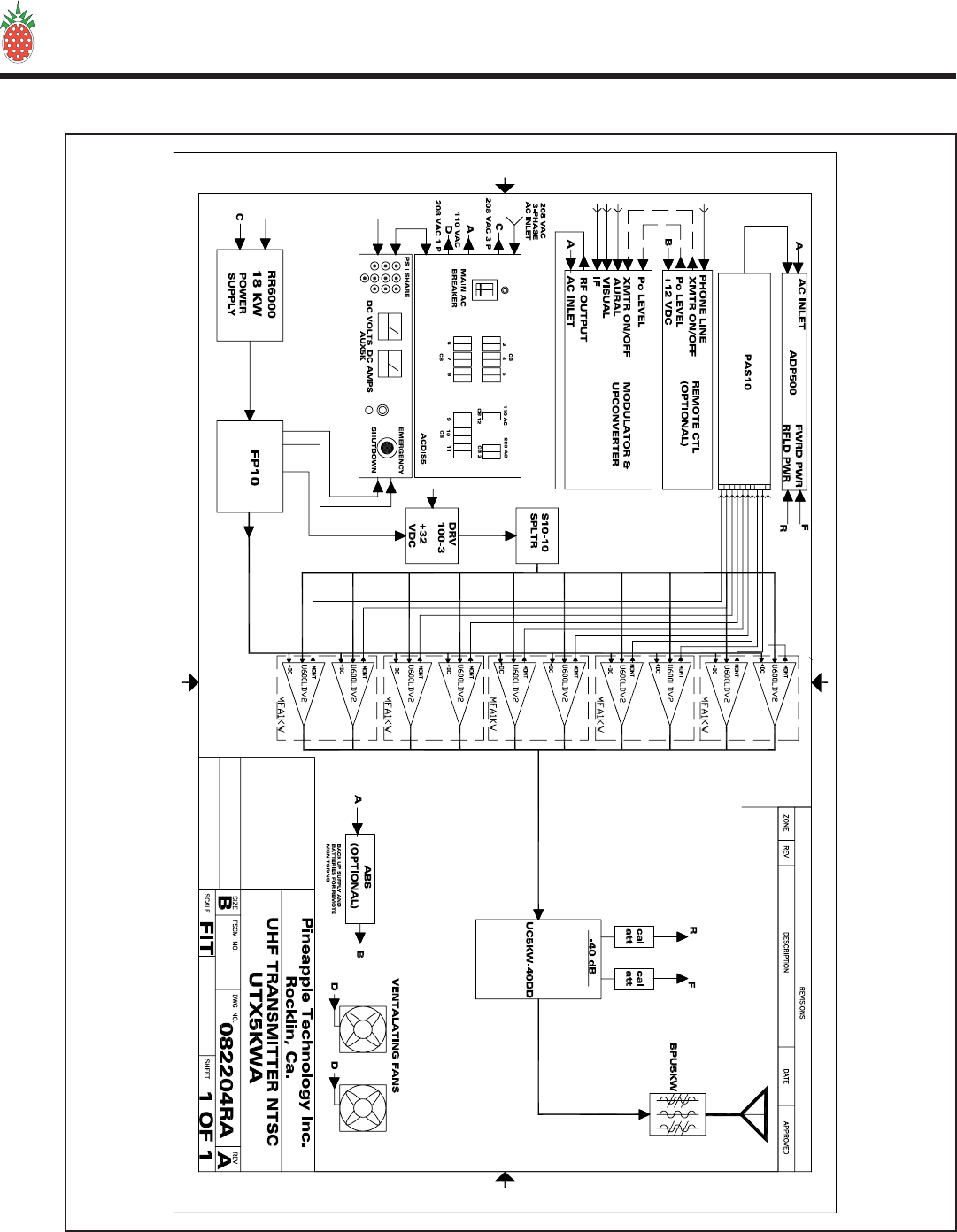
Refer to the UTX5KW-A block diagram – gure 1 (page 8) for an overview of the transmitter architecture.
SEE SECTION VI.A (page 14) FOR PARTS LIST
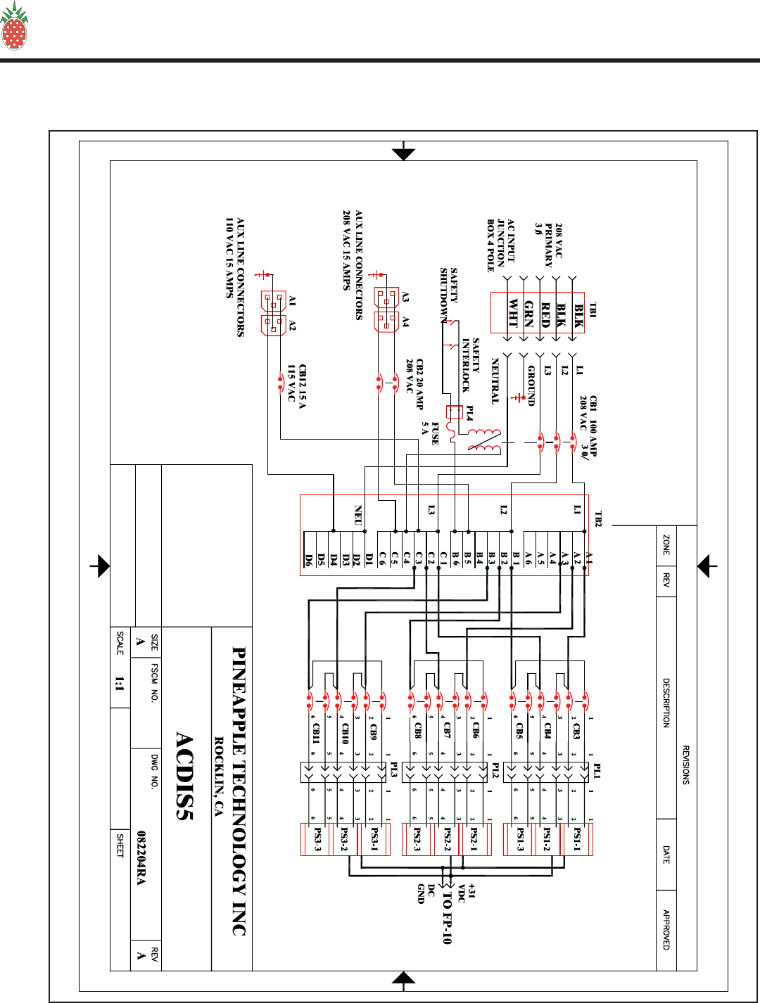
B. ACDIS5 AC DISTRIBUTION
The ACDIS5 is the primary AC power inlet module. The UTX5KW-A transmitter was designed to except
208 to 230 V AC 3-PHASE using a FIVE (5) wire connection. The ve wires are:
• 3 wires for 208-230V AC 3-Phase
• 1 wire for neutral connection
• 1 wire for safety ground connection
CAUTION: Connection to the AC Primary Source must be made using all ve wires listed above. Follow
the wiring instruction given in the AC WIRING SECTION (III. 3.; page 5), If not followed, severe damage
to the transmitter and or electrical shock is possible.
The ACDIS5 performs the following functions:
1. Provides a primary AC power breaker point to shutdown the transmitter.
2. Provides 208 VAC to each of the 2 KW DC power supplies with individual breaker points for added
safety.
3. Provides 110 VAC circuits for Modulator, ADP500, ABS (auxiliary backup power supply), and AUX
Power where needed.
4. Provides 208 VAC to power cooling and exhaust fans.
SEE SECTION VI.B (page 15) FOR SCHEMATIC AND PARTS LIST
C. RR6000 POWER SUPPLY
The UTX5KW-A transmitter is designed with over 18 KW of DC power available to the transmitter. To
achieve this level, the power supply is made up of nine (9) RR6000 power module mounted into three (3)
main frame assemblies which are capable of managing three (3) 2 KW modules each.
The power modules are “HOT PLUGGABLE” and can be removed or installed without turning off the
transmitter.
Each power supply module has OVER VOLTAGE, OVER CURRENT, and OVER TEMPERATURE
protection as well as a fault signal in the event of a failure.
REFER TO MANUFACTURER’S MANUAL PROVIDED WITH THE UTX5KW-A.
V — THEORY OF OPERATION
Page 7
PINEAPPLE TECHNOLOGY, INC.
UTX5KW-A Operating and Service Manual V — THEORY OF OPERATION
Page 8
UTX5KW-A Block Diagram (gure 1)

PINEAPPLE TECHNOLOGY, INC.
UTX5KW-A Operating and Service Manual
D. ADP500 & PAS10 PERFORMANCE MONITOR
The ADP500 & PAS10 (PERFORMANCE MONITOR) provides the following functions:
1. Monitors FORWARD AND REFLECTED POWER to the antenna and presents it as a percentage of
power rating. The transmitter comes set to 100% P-Sync power based on the ratings of the transmitter
or service requirements.
2. Monitors Aural Power as a percentage of P-Sync rating (5-10% typical)
3. Provides a HIGH ANTENNA VSWR MONITOR In the event of an antenna or coax failure where
the reected power exceeds 25% the transmitter will shutdown. Front panel LED will change from
green to red in case of a fault.
4. Provides current monitoring of all the pallets used in the ten (10) U600LDV-2 power amplier
assemblies. The current levels can be read directly from the multi-meter on the front panel. Individual
pallets are selectable on the ADP500, and the PA assemblies are selected using the PAS10. In normal
operations, a PA FAULT is indicated by going from green to red. RED indicates that the current level
is below 500 ma and a transistor could have failed. To read the actual current, select the appropriate PA
Bank using the PAS10. The ADP500 will now display status of each pallet in that PA. The multi-meter
will read the actual current.
5. A PA INHIBIT switch is provided for failure diagnostic purposes. When activated, this switch allows
the technician to monitor the bias currents for each pallet. These readings should be recorded when
the transmitter is rst installed and used as a reference. This is the best way to trouble shoot possible
transistor problems. When in the PA INHIBIT mode, the RF PWR OFF LED will change from green
to red indicating that the “SHUTDOWN LINE” Is at a TTL 0 state and the output power has been
reduced to near zero.
6. An RF MONITOR port (BNC) is available to connect a spectrum analyzer for monitoring the output
signal.
METER SELECTOR SWITCHES
The PAS10 is used to select the appropriate PA Module ( U600LDV-2) for performance display on the
ADP500. PA designations are PA1 starting from the top row going left to right with PA10 being on the
right side in the fth (5th) row down when viewed from the front of the transmitter.
The Rotor Switch on the ADP500 is the detail selector for the multi-meter. The various positions are
dened as follows:
PA1 THRU PA5 ................................................... Reads PA pallet currents as selected
Typical reading in INHIBIT MODE 1.5 TO 2.2 A
Typical reading with SMTPE BARS — 5-7 A for PA1
thru PA4 Typical reading with SMTPE BARS — 2-3 A
for PA5
PA6 ..................................................................... NO CONNECTION
PS VOLTS............................................................ Reads DC Voltage applied to PA Stages
Typical reading would be +29 to 32 VDC
P FWRD .............................................................. Reads PA output power in P-Sync percentage of rating.
Full power reading would be 100%
V — THEORY OF OPERATION
Page 9

PINEAPPLE TECHNOLOGY, INC.
UTX5KW-A Operating and Service Manual
P RFLD................................................................ Reads PA output power being returned from the load an
displayed as a percentage of forward power. Typical reading
would be < 5% indicated.
P AURAL............................................................. Reads the AURAL POWER component as a percentage of
forward power. Typical reading would be 10%.
AUX 1 & AUX 2 ................................................. not used in this conguration.
REFER TO SECTION VI.H. (page 37) FOR SCHEMATICS AND PARTS LIST.
E. REMOTE MONITOR AND CONTROL WITH ABS (AUXILIARY POWER SUPPLY)
This equipment is OPTIONAL and can be used to satisfy FCC remote control requirements.
The Remote Monitor is used to monitor the operational status of the transmitter and will allow the operator to turn
RF on or off and adjust power levels. The following items are monitored or controlled:
1. RF Power on/off function
2. Power output level monitor and adjust.
3. AC Line voltage status. With ABS you can be notied if there is a power failure at the side.
4. Various other custom options are available. Specify these at the time the transmitter is purchased and they
will be included if possible.
Remote monitoring requires a Phone line connection. Information can be accessed via a PC Terminal or via a
“VOICE COMMAND LINE.” Either option is standard with this system.
The Auxiliary power unit requires a battery connection. A common car battery (12 VDC) can be used with a
charger as an ABS. This will run the Monitor and provide access to transmitter status for several hours.
A manual for this equipment is provided by the Manufacturer and is included in the UTX5KW-A package
shipped with the transmitter. This manual is only included if this option was purchased for delivery with
the transmitter.
REFER TO INSTRUCTION MANUAL PROVIDED WITH THIS PACKAGE.
F. MODULATOR/UPCONVERTER
The heart of any TV Transmitter is the “MODULATOR”. This equipment receives the video and audio signals
as well as any control signals needed. The base band signals are converted to RF with an output on the desired
operating channel.
Detail operation of the Modulator with schematics and parts list is provided by the equipment manufacturer.
REFER TO INSTRUCTION MANUAL PROVIDED WITH THIS PACKAGE.
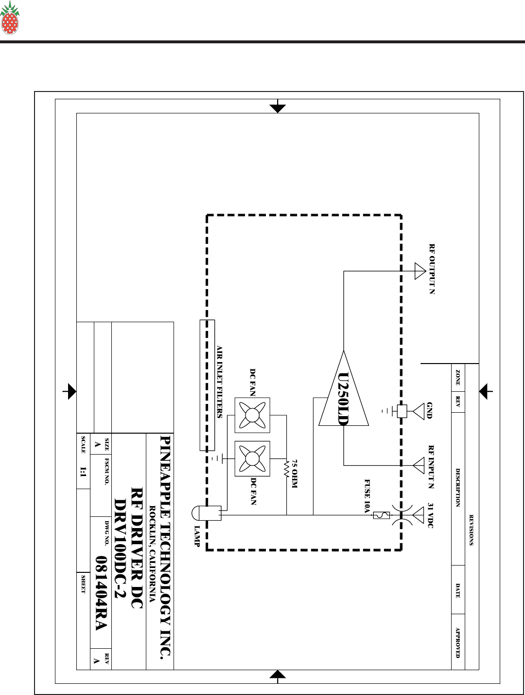
G. DRV100DC-3 DRIVER
The output power of the modulator is applied to the input of the DRV100DC-3 driver. This amplier increases the
drive level to that required for the MFA1KW to make rated power. The driver amplier requires 31 VDC to operate
and does not require any tuning or adjustments to change channels.
REFER TO SECTION VI.C. (page 17) FOR SCHEMATIC AND PARTS LIST.
V — THEORY OF OPERATION
Page 10

PINEAPPLE TECHNOLOGY, INC.
UTX5KW-A Operating and Service Manual
H. S10-10 SPLITTER
The S10-10 SPLITTER is a 10-way in-phase broadband splitter. This splitter provides an equal split of drive
power to each U600LDV-2 power amplier.
SEE SECTION VI.F. (page 35) FOR PARTS LIST.
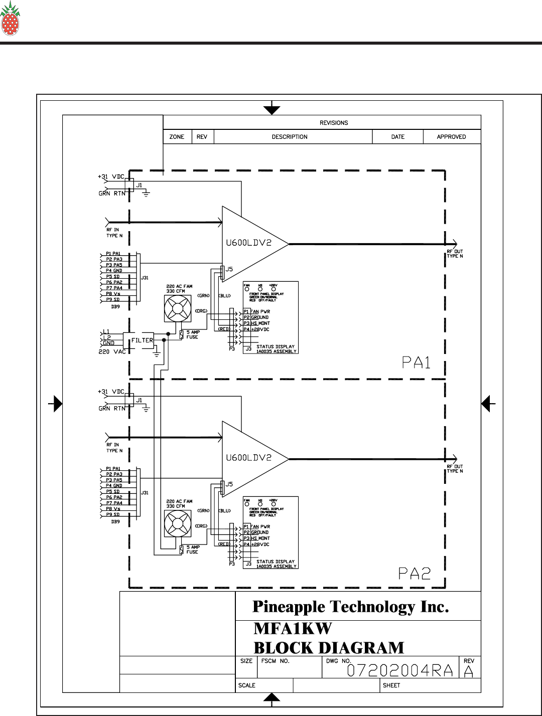
I. MFA1KW PA HOUSING
The MFA1KW is the main RF Power Amplier housing which accommodates two (2) U600LDV-2 Ampliers.
The housing includes the following:
2 ea....................................................................... 330 CFM cooling fans
2 ea....................................................................... Air lter assemblies
2 ea....................................................................... Front panel status PC Boards
1 ea....................................................................... Main chassis
2 ea....................................................................... Mechanical slide assemblies
1 ea....................................................................... AC Filtered inlet for cooling fans
SEE SECTION VI.D. (page 19) FOR SCHEMATICS AND PARTS LIST
J. U600LDV-2 POWER AMPLIFIER
The U600LDV-2 is the main RF Power Amplier Assembly used in the UTX5KW-A. Each Amplier
assembly is made up of ve (5) U250LD power pallets. Each power pallet uses two (2) Philips BLF861A
power LDMOS FETs. These ampliers are operated in Class A/AB or sometimes referred to as “HARD AB.”
This refers to the bias levels to achieve best linearity.
Each U600LDV-2 amplier assembly includes the following:
5 ea....................................................................... U250LD power pallets
1 ea....................................................................... 4-way splitter
1 ea....................................................................... 4-way combiner
1 ea....................................................................... phase & gain matching circuit (1A0018)
1 ea....................................................................... Pwr distribution module (1A0025)
1 ea....................................................................... high power isolator
3 ea....................................................................... thermal sensors
1 ea....................................................................... remote monitor port (DB9)
1 ea....................................................................... front panel status port (molex)
1 ea....................................................................... ltered DC input port
1 ea....................................................................... Type N panel mounted RF Input port
1 ea ...................................................................... Type N Panel mounted RF Output port
SEE SECTION VI.E. (page 23) FOR SCHEMATICS AND PARTS LIST.
K. UC5KW-DC40 COMBINER/DD COUPLER
The UC5KW is a 10-way in phase combiner with built in 40 dB dual directional coupler. The combiners are
designed for the channel designated for the transmitter. This is a closed unit and can not be serviced.
SEE SECTON VI.G. (page 36) FOR PARTS LIST
V — THEORY OF OPERATION
Page 11

PINEAPPLE TECHNOLOGY, INC.
UTX5KW-A Operating and Service Manual
L. BPU5KW UHF BAND PASS FILTER
This Band Pass lter was designed to meet FCC Certication requirements with minimum loss of RF
Power. The BPU5KW comes tuned and tested to the operating frequency of the transmitter and should
not be adjusted without proper equipment. Replacement lters are available as P/N BPU5KW UHF
(+CHANNEL NUMBER).
M. AUX5 MONITOR PANEL
The auxiliary monitor panel provides analog meter measurements for the primary DC supply. The total
power supply current and voltage are displayed on these meters. These measurements serve as a good
indication of the operations of the transmitter nal power ampliers.
Each power supply has a current monitor output. These outputs are accessible on the AUX5 Front panel.
Each ( PS I SHARE ) test point will indicate a relative amount of current being supplied from the power
supply. This is not a calibrated or accurate measurement that is scaled from the current capability of the
power supply. This is also a second-level diagnostic tool for use by qualied technicians.
In the event of an EMERGENCY, a SHUTDOWN SWITCH located on the AUX5 will shut down the
transmitter and remove all power starting from the MAIN 3-P BREAKER. To turn the transmitter on,
it is necessary to RECYCLE the SHUTDOWN SWITCH before the transmitter MAIN BREAKER can
be turned on.
N. FP-10 FUSE AND SHUNT PANEL
The FP-10 serves as a DC SUMMING POINT for all current coming from the power supplies. After being
summed the current passes through a 500 AMP precision shunt which is used for measuring the total
supply current and voltage being applied to the transmitter power ampliers. At this point, the DC Power
is distributed to each U600LDV-2 amplier assembly thru a series 80 amp fuse.
NOTICE: BEFORE ANY SERVICE WORK IS PERFORMED ON THE FP-10 ALL POWER TO
THE TRANSMITTER MUST BE TURNED OFF FOR SAFETY.
V — THEORY OF OPERATION
Page 12

PINEAPPLE TECHNOLOGY, INC.
UTX5KW-A Operating and Service Manual
Page 13
VI — SCHEMATICS AND PARTS LIST
VI — SCHEMATICS AND PARTS LIST
A. UTX5KW-A — Schematic

PINEAPPLE TECHNOLOGY, INC.
UTX5KW-A Operating and Service Manual VI — SCHEMATICS AND PARTS LIST
Page 14
VI — SCHEMATICS AND PARTS LIST
A. UTX5KW-A — Parts List
Item Qty Type P/N Title Detail Ref(m)
Printed 9/7/2004
UHF TV TRANSMITTER
5 KW WITH TWO RACKS
Type
Status
Revision
CAT
U
A
User1
User2
User3
User4
User5
Date
By
9/1/2004
RA
UTX5KWATop CAT UHF TV TRANSMITTER 5 KW WITH TWO
RACKS
BPU5KW1 1 CAT BP FILTER UHF TV 5 KW P-SYNC RATING
85102622PS FAN AC 208 2000 CFM
EXHAUSE MULTIFAN
VOSTERMANS
4VF1042A
AC810031PS AC WIREMOLD 19
RACK MTG 1 X 4 OUTLETS 6 FT
CORD
MODULATOR
CAV5
41CAT MODULATOR/DRIVER
5 W UHF ELECTRONICA
ITALY
ADP50051CAT DISPLAY PANEL,
ANALOG SEL SW AND METER
MFA1KW6 5 PL 1 KW MAIN FRAME UHF/VHF
ASSEMBLIES
AC20067 9 PS AC POWER SUPPLY 600W 32 V DC 110/220
VAC
AC200983PL 6KW 3EA PWR
SUPPLY MAIN FRAME UNIPOWER RRS2U
R40RU-HAM9 2 PL XMTR RACK 40 RU HAMMOND MFG
PAS1010 1 CAT PA SEL SW FOR
ADP500 10 POLE INPUT 1
OUTPUT
FP-1011 1 CAT FUSE PANEL
UTX5KWA INC FUSES, SHUNT,
AND COVER SHIELD
AUX5K12 1 CAT AUX PANEL 5KW USED ON 3, 4, 5 KW
XMTRS
DRV100-313 1 CAT DRIVER AMP WITH 2
STAGES +31 VDC SUPPLY
S10-1014 1 CAT SPLITTER UHF
10-WAY
UC5KW-40DD15 1 CAT 5 KW 10-WAY
COMBINER
W/DDCOUPLER
1 5/8 OUTPUT
W/TYPE N INPUTS
PINEAPPLE TECHNOLOGY, INC.
4021 ALVIS COURT, #6, ROCKLIN, CA 95677
916-315-8338 Fax 916-315-8118
UTX5KWA
1Page 1 o
f
PINEAPPLE TECHNOLOGY, INC.
UTX5KW-A Operating and Service Manual
Page 15
VI — SCHEMATICS AND PARTS LIST
VI — SCHEMATICS AND PARTS LIST
B. ACDIS5 — SCHEMATIC

PINEAPPLE TECHNOLOGY, INC.
UTX5KW-A Operating and Service Manual VI — SCHEMATICS AND PARTS LIST
Page 16
VI — SCHEMATICS AND PARTS LIST
B. ACDIS5 — Parts List
Item Qty Type P/N Title Detail Ref(m)
Printed 9/20/2004
AC DISTRIBUTION PANEL
3-PHASE SPLIT OUT
Type
Status
Revision
PL
U
A
User1
User2
User3
User4
User5
Date
By
6/30/2004
RA
ACDIS5Top PL AC DISTRIBUTION
PANEL 3-PHASE SPLIT OUT
AC3210011PS AC BKR 3-PHASE 100
AMP W/TRIP COIL
AC32202 10 PS AC CKT BRKR 20 AMP 2-POLE 22O V
MF928631PS PLATE, FRNT
BREAKER PANEL ACDIS 5
AC412043PS AC POWER SOCKET 7
PIN BULGIN PX093/07/S
1143305 3 PS RES ARRAY, SMT 330 OHMS
AC411061PS AC POWER PLUG 7
PIN BULGIN PXA911/07/P
MF928881PS TOP, COVER
BREAKER PANEL
MF928791PS ACDIS3, 4, AND 5
CHASSIS
63000110 1 PS INDICATOR LITE RED 220 VAC 1/2W
AC800011 1 PS AC POWER
DISTRIBUTION BLOCK 3 POLE 840 A 60O
VAC
PINEAPPLE TECHNOLOGY, INC.
4021 ALVIS COURT, #6, ROCKLIN, CA 95677
916-315-8338 Fax 916-315-8118
ACDIS5
1Page 1 o
f
PINEAPPLE TECHNOLOGY, INC.
UTX5KW-A Operating and Service Manual
Page 17
VI — SCHEMATICS AND PARTS LIST
VI — SCHEMATICS AND PARTS LIST
C. DRV100DC-2 — Block Diagram

PINEAPPLE TECHNOLOGY, INC.
UTX5KW-A Operating and Service Manual VI — SCHEMATICS AND PARTS LIST
Page 18
VI — SCHEMATICS AND PARTS LIST
C. DRV100DC-2 — Parts List
Item Qty Type P/N Title Detail Ref(m)
Printed 9/7/2004
DRIVER ASSEMBLY
31 VDC WITH 1 U250LD
Type
Status
Revision
CAT
U
A
User1
User2
User3
User4
User5
Date
By
6/7/2004
RA
DRV100DC-2Top CAT DRIVER ASSEMBLY 31 VDC WITH 1
U250LD
6310011 1 PS INDICATOR LAMP LED GREEN 24 VDC 1/2 IN
MTG HOLE
MF93372 1 PS PANEL, FRONT DRV100DC
MF9338A3 1 PS CHASSIS DRV100DC
MF9339A4 1 PS DIVIDER AIR FLOW DRV100DC
MF9340A51PS TOP COVER
DRV100DC
99020162PS FILTER & FINGER
GUARD 80X25mm FAN 30 PPI
8510057 2 PS FAN DC 24 V 80X25mm COMAIR-ROTRON
27047N8 1 PS FT CAP 47NF DC 1/4-20 HW MTG
THRU PANEL
U250LD9 1 CAT UHF TV 300 W P 470-810 MHz
14001210 1 PS RES AXIAL TH 2 WATT 75 OHM METAL
OXIDE
14001011 1 PS RES AXIAL 2 W 10 OHM
PINEAPPLE TECHNOLOGY, INC.
4021 ALVIS COURT, #6, ROCKLIN, CA 95677
916-315-8338 Fax 916-315-8118
DRV100DC-2
1Page 1 o
f
PINEAPPLE TECHNOLOGY, INC.
UTX5KW-A Operating and Service Manual
Page 19
VI — SCHEMATICS AND PARTS LIST
VI — SCHEMATICS AND PARTS LIST
D. MFA1KW — Block Diagram

PINEAPPLE TECHNOLOGY, INC.
UTX5KW-A Operating and Service Manual
VI — SCHEMATICS AND PARTS LIST
D. MFA1KW — Parts List
Page 20
VI — SCHEMATICS AND PARTS LIST
Item Qty Type P/N Title Detail Ref(m)
Printed 8/16/2004
1 KW MAIN FRAME
UHF/VHF ASSEMBLIES
Type
Status
Revision
PL
U
A
User1
User2
User3
User4
User5
Date
By
1/24/2000
RA
MFA1KWTop PL 1 KW MAIN FRAME UHF/VHF
ASSEMBLIES
MF9100E1 1 PS MAIN CHASSIS MFA1KW
MF91012 1 PS DIVIDER, PLENUM MFA1KW
MF9102C3 1 PS DIVIDER, FAN MFA1KW
MF91045 1 PS COVER, TOP MFA1KW
MF913910 4 PS SLED GUIDE U600LP & MFA1KW
MF9123D11 1 PS FRONT PANEL,
PAINTED MFA1KW
99019914 2 PS FILTER, AIR DRY FF-5 MFA/PS FP
MF912716 2 PS MTG BRACKET,
MOLEX FMALE MFA1KW
48047217 6 PS MOLEX CRIMP TERM
MFA1KW MOLEX MFG
39-00-0041
48040018 2 PS MOLEX PLUG 6 TERM
MFA1KW MOLEX 15-06-0065
MINI-FIT BMI
46015019 2 PS FUSE HOLDER PANEL
MTG 3AG TYPE QC CON
1A003520 2 PL PA STATUS BOARD PC9061A
INHOUSE_LABOR22 4 PS PTI LABOR
U600LDV223 2 PL 600W UHF AMPLIFIER
MODULE USED WITH MFA1KW
ASSEMBLY
MF930824 2 PS FAN FINGER GUARD MFA1KW & U600LPA
MF931025 2 PS AC FAN INLET
HOLDER MFA1KW
MF925827 2 PS BRACKET FILTER MTG
PAINTED U600LPA & MFA1KW
MF9197B28 1 PS DIVIDER PA MFA1KW
85102529 2 PS FAN, AC 220 V COMAIR ROTRON
TN3A2
AC511030 2 PS AC FAN PLUG & CORD FMALE PLUG 24 IN
CORD
PINEAPPLE TECHNOLOGY, INC.
4021 ALVIS COURT, #6, ROCKLIN, CA 95677
916-315-8338 Fax 916-315-8118
MFA1KW
1Page 1 o
f
PINEAPPLE TECHNOLOGY, INC.
UTX5KW-A Operating and Service Manual VI — SCHEMATICS AND PARTS LIST
Page 21
VI — SCHEMATICS AND PARTS LIST
D. MFA1KW
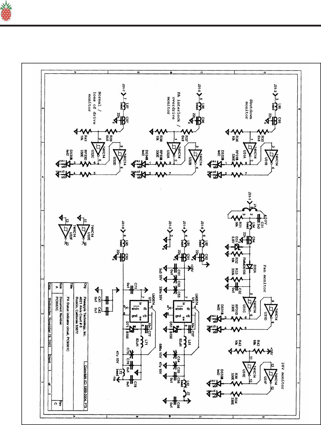
1. 1A0035 STATUS BOARD

PINEAPPLE TECHNOLOGY, INC.
UTX5KW-A Operating and Service Manual
Page 22
VI — SCHEMATICS AND PARTS LIST
VI — SCHEMATICS AND PARTS LIST
D. MFA1KW
1. 1A0035 PARTS LIST
Item Qty Type P/N Title Detail Ref(m)
Printed 8/16/2004
PA STATUS BOARD
PC9061A
Type
Status
Revision
PL
U
B
User1
User2
User3
User4
User5
Date
By
8/1/2002
RA
1A0035Top PL PA STATUS BOARD PC9061A
1143301 2 CAT RES ARRAY, SMT 330 OHMS RP31, RP32
1151032 5 PS RES CHIP 0805 10K OHM SMT 0805 R32,36,38,4
1,43
1153343 1 PS RES CHIP 0805 330 K OHM SMT R33
1155634 1 PS RES CHIP 0805 56K OHM 0805 SM R31
1156825 3 PS RES CHIP 0805 6.8 K OHM SMT R35,37,39
21X0056 6 PS CAP CHIP 0805 100NF 10% XTR 0805
CASE C32,41,42,5
1,56,58,71,
21X0087 1 PS CHIP CAP 0805 10NF 50 V 0805 SM C57,
24010981PS CAP TH
POLYPROPYLENE 3N3 600 WVDC
.033UF C31
2401109 1 PS CAP TAN SMD 3.3 UFD 35 V C52
24011110 1 PS CAP TAN SMD 47 UF 10 V TAN C55,
24130011 1 PS CAP RADIAL TH 330 UF 35 VDC C53
24130112 1 PS CAP RADIAL TH 680 UF 10 V
ELECTROLYTIC C54
27022N13 6 PS FT CAP 22N SM AVX OR MURRATA
PART C91, 92, 94,
95, 96,
97,93
48050014 1 PS CON MICRO-FIT
HEADER 3.0 8 PIN PC MTG J31
52023015 1 PS SEMI DIODE
SHOTTKEY 1.5 A 60 VDC D-64 D51
52027516 1 PS SEMI, DIODE DUAL FMMD6100 D32
53035017 2 PS HEX SCHMITH TRIG 74HD14 U31, U32
53815018 1 PS IC SWITCHER SIMPLE SO8 PAK U51,
63020019 5 PS IND LED DUAL COLOR RED/GREEN T1-3/4
CLR DS31,32,33,
34.35
75000120 8 PS FERRITE BEAD SMT 0805 EMI FERRITE
BEAD L52
,91,92,94,95
,96,97,72
83051021 1 PS IND, W/W 82 UH .58A PWR SMD L51,
PC906122 2 PS PA STAUS BRD FR4 060 1/1 CBR
11533123 2 PS RES CHIP 0805 33O OHM SMT R30,34
52012024 1 PS SEMI ZENER 5.6 V MELF D31
11568325 1 PS RES CHIP 0805 68K SM R42
PINEAPPLE TECHNOLOGY, INC.
4021 ALVIS COURT, #6, ROCKLIN, CA 95677
916-315-8338 Fax 916-315-8118
1A0035
1Page 1 o
f
PINEAPPLE TECHNOLOGY, INC.
UTX5KW-A Operating and Service Manual VI — SCHEMATICS AND PARTS LIST
Page 23
VI — SCHEMATICS AND PARTS LIST
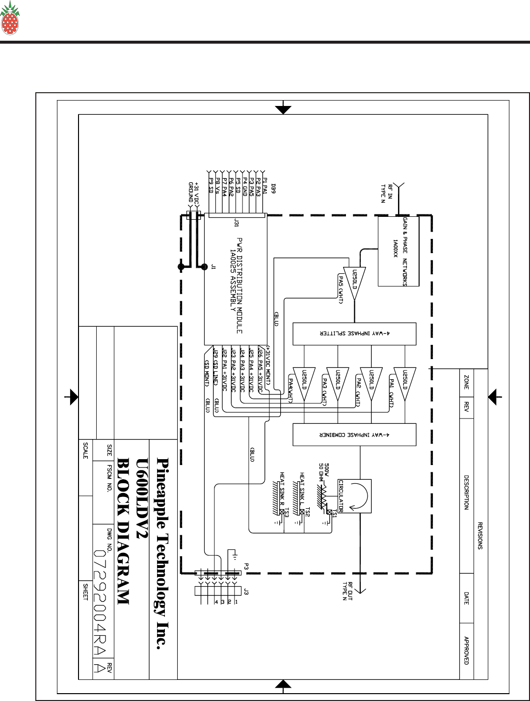
E. U600LDV-2 — Block Diagram

PINEAPPLE TECHNOLOGY, INC.
UTX5KW-A Operating and Service Manual
Page 24
VI — SCHEMATICS AND PARTS LIST
VI — SCHEMATICS AND PARTS LIST
E. U600LDV-2 — Parts List
Item Qty Type P/N Title Detail Ref(m
Printed 8/16/2004
600W UHF AMPLIFIER MODULE
USED WITH MFA1KW ASSEMBLY
Type
Status
Revision
PL
U
A
User1
User2
User3
User4
User5
Date
By
1/21/2004
RA
U600LDV2Top PL 600W UHF AMPLIFIER
MODULE USED WITH MFA1KW
ASSEMBLY
U4002-1T1 1 PS UHF CIR 3T DITOM DF4002 470-540 MHz
MF9126C21PS MOLEX BRACKET
MTG PLATE U600LD ALL
3100103 3 PS SW THERMAL 140 DEG F N/C
MF9160C4 1 PS HEAR SINK U600LD RIGHT SIDE
MF9159G5 1 PS HEAT SINK U600LD LEFT SIDE
1A001861PL PHASE & GAIN
MATCHING UHF U500/U600LD ASS'Y
MF9118A7 1 PS BASE PLATE, US200 Al 1/2 IN
MF91378 1 PS SLED U500L AL
4540019 1 PS HANDLE, REAR BLK NYLON
PC9033_3410 1 PS PC BRD JUMPER U600LD RGR 4003
060
PC9023B11 2 PS PCB COMB/SPLTR R-4003 060 1/1
180040-100R12 4 PS RES PWR 40 W 100 OHM RES
180150-100R13 2 PS RES PWR 150 W 100 OHM RES
180250-50T14 1 PS RES PWR 250 W 50 OHM TERM
44010115 2 PS HW CS STANDOFF 1.0 x .375;
Male/Female; 1032
MF9203 B116 1 PS PLATE, ISO/MONT
BRD SM 09 AL W/MTG
MF9202B117 1 PS COVER, REAR U600LD SM 09 AL
MF9206AMU18 1 PS Shield, PC9050A PCB SHIELD
MONITOR/ISO BRD
1A002519 1 PL DC ISO/MONITOR CKT REPLACED CB99
MF9075A20 3 PS CIR MOUNTING PLT O.O9 ALUM
45200121 1 PS HWRD TERM FEED
THRU BLK 5 PIN; #10 STUD;
10-16 AWG
45205022 1 PS HWR TERM BLK
COVER 5 PIN COVER W/MTG
HWRD
48040123 1 PS MOLEX RECEPTACLE
U600LD MOLEX 15-06-0061
48047324 3 PS MOLEX CRIMP
TERMINAL U600LD MOLEX 39-00-0039
FEMALE
CA500125 1 PL COAX CABLE
ASSEMBLY RG142 TO N PM FM 4
HOLE FLG
PINEAPPLE TECHNOLOGY, INC.
4021 ALVIS COURT, #6, ROCKLIN, CA 95677
916-315-8338 Fax 916-315-8118
U600LDV2
2Page 1 o
f

PINEAPPLE TECHNOLOGY, INC.
UTX5KW-A Operating and Service Manual VI — SCHEMATICS AND PARTS LIST
Page 25
VI — SCHEMATICS AND PARTS LIST
E. U600LDV-2 — Parts List (Cont.)
CA503026 1 PL COAX CABLE
ASSEMBLY ANDREWS ETS1 TO N
PANEL FLG MT
49160027 1 PS N FEMALE BULK
CRIMP REAR MNT W/ "O"
RING
U250LD28 5 CAT UHF TV 300 W P 470-810 MHz
INHOUSE_LABOR29 6 PS PTI LABOR
MF930930 1 PS REAR PANEL WITH
SILK 090 AL ALODYNE
Item Qty Type P/N Title Detail Ref(m
U600LDV2
Printed 8/16/2004
Rev A
600W UHF AMPLIFIER MODULE
USED WITH MFA1KW ASSEMBLY
PINEAPPLE TECHNOLOGY, INC.
4021 ALVIS COURT, #6, ROCKLIN, CA 95677
916-315-8338 Fax 916-315-8118
U600LDV2
2Page 2 o
f
PINEAPPLE TECHNOLOGY, INC.
UTX5KW-A Operating and Service Manual
Page 26
VI — SCHEMATICS AND PARTS LIST
VI — SCHEMATICS AND PARTS LIST
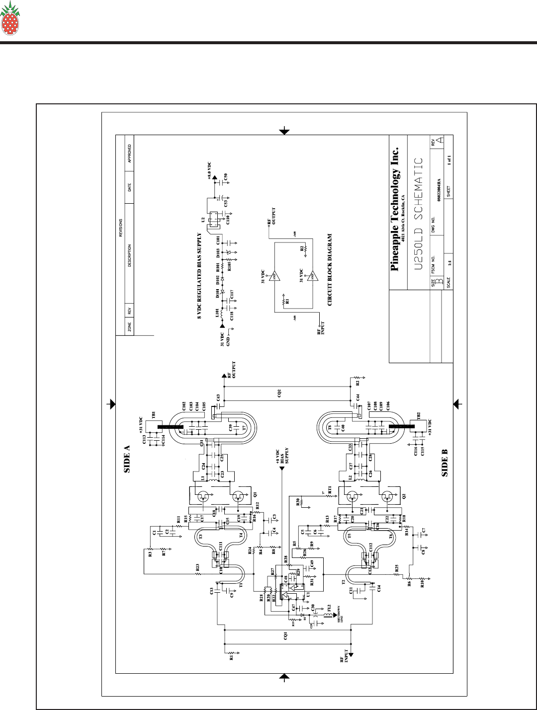
E. U600LDV-2
1. U250LD — Schematic
PINEAPPLE TECHNOLOGY, INC.
UTX5KW-A Operating and Service Manual VI — SCHEMATICS AND PARTS LIST
Page 27
VI — SCHEMATICS AND PARTS LIST
E. U600LDV-2
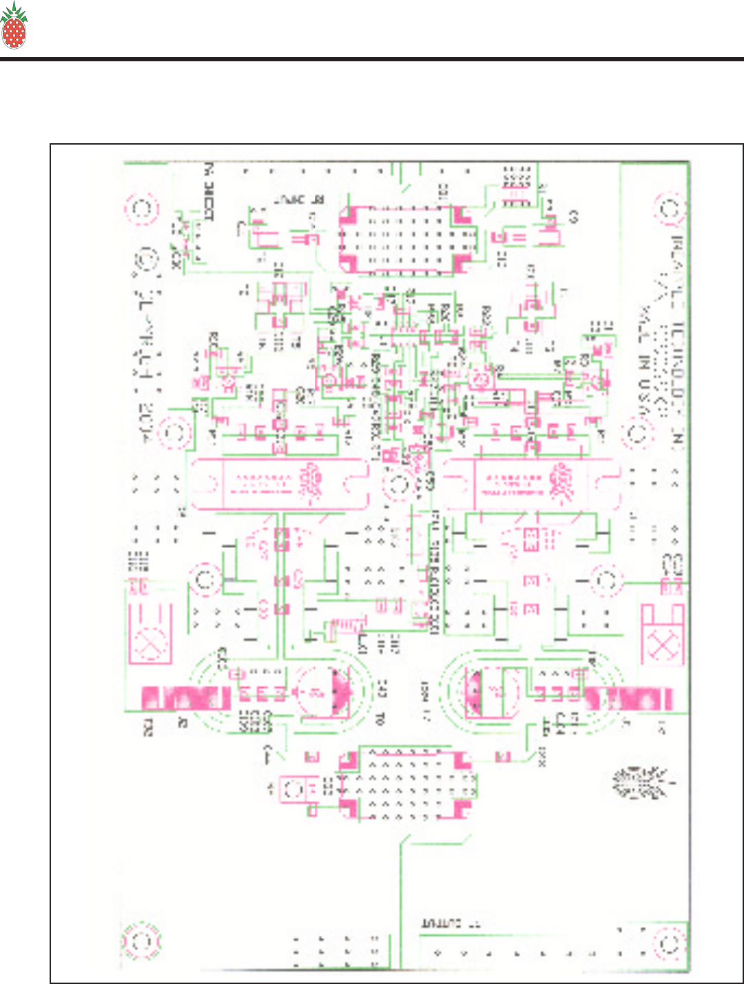
1. U250LD — Layout Drawing

PINEAPPLE TECHNOLOGY, INC.
UTX5KW-A Operating and Service Manual
Page 28
VI — SCHEMATICS AND PARTS LIST
VI — SCHEMATICS AND PARTS LIST
E. U600LDV-2
1. U250LD — Parts List
Item Qty Type P/N Title Detail Ref(m)
Printed 8/16/2004
UHF TV 300 W P
470-810 MHz
Type
Status
Revision
CAT
U
A
User1
User2
User3
User4
User5
Date
By
11/5/2003
RA
U250LDTop CAT UHF TV 300 W P 470-810 MHz
PC9069C11PS U300LD 470-860 MHz
TV FR4 060 1/1
53073722PS LDMOS PWR FET UHF
TV BLF861A PHILIPS Q1,2
5601074 1 PS DUAL OP AMP 8-SOIC TLV272IDR U1
1174446 1 PS THERMISTOR 33K OHM RT1
180030-50T7 1 PS RES PWR 30 W SMT RFP-30-50T RFPC R1
180010-50T8 1 PS RES PWR 10 W 50 OHM TERM R2 ((NO
LOAD))
17L2029 4 PS RES VAR SMT 2K OHM POT R3,4,5,6
11620210 4 PS RES CHIP 1206 2K OHM SMT R7,8,9,10
11610311 10 PS RES CHIP 1/8 W 10 K OHM SM 1206 R11,12,13,
14,19,20,22
,30,31,105
11601012 4 PS RES CHIP 1206 10 OHM SM R15,16,17,
18
11610213 1 PS RES CHIP 1/8 1 K OHM SM 1206 R21,
11600014 2 PS RES CHIP 1206 0.0 OHMS SM R27,28,
11682215 1 PS RES CHIP 1206 8.2K OHM 1/8 W SMT R29
21Y04219 14 PS CAP CHIP 0.1 UF 50 V 1206 C1,3,5,7,47
,48,49,101,
105,109,11
0,113,115,1
17
21X00120 11 PS CAP CHIP 0805 100 PF 50V SMD C2,4,6,8,29
,50,102,106
,114,116,11
8
26330121 6 PS CAP CHIP ATC 300 PF B CASE C9,11,103,
107,111,11
2
2631R822 2 PS CHIP CAP ATC 1.8PFBCASE C10,12
26318023 4 PS CAP CHIP ATC 18 PF B CASE C15,16,
26320024 2 PS CAP CHIP ATC 18-20 PF B CASE C18,21
((NO
LOAD))
27022N26 1 PS FT CAP 22N SM AVX OR MURRATA
PART C30
24122029 2 PS CAP RADIAL SM 220 UF 50 V HA C39,40
PINEAPPLE TECHNOLOGY, INC.
4021 ALVIS COURT, #6, ROCKLIN, CA 95677
916-315-8338 Fax 916-315-8118
U250LD
2Page 1 o
f

PINEAPPLE TECHNOLOGY, INC.
UTX5KW-A Operating and Service Manual VI — SCHEMATICS AND PARTS LIST
Page 29
VI — SCHEMATICS AND PARTS LIST
E. U600LDV-2
1. U250LD — Parts List (Cont.)
75000130 1 PS FERRITE BEAD SMT 0805 EMI FERRITE
BEAD FL2
52012931 1 PS SEMI DIODE GP 1N914 SM SOT-23 D2,102,
45107033 2 PS HW PWR TAP 6-32 STL KEYSTONE
8191 TB1,TB2
52011834 3 PS SEMI ZENER 14V MINI 3P
MA3140CT D101,103,
56011635 1 PS 8VDC SMT
REGULATOR TK11280CMCL U2
24101036 1 PS CAP RADIAL SM 10UF 16V ALUM ELEC C53
2638R237 6 PS ATC CHIP CAP 8.2 PF B CASE C23,24,26,
27,((23,26
NO LOAD))
2636R838 4 PS CAP CHIP ATC 6.8 PF B CASE C25,28,31,
33
26310139 10 PS CAP CHIP ATC 100 PF B CASE C13,14,17,
19,20,22,43
,44,104,108
,
83043040 1 PS IND CHIP W-W AIR COIL 43.0 NH
SMT L101
11647141 5 PS RES CHIP 1206 470 OHM 1/8 W SMT R101,
R23,24,25,
26
PAC000142 2 PS MATCHING XFMR RG316 CUT & TRIM T1,2
PAC000243 2 PS MATCHING XFMR
COXIAL UT90-25 CUT & TRIM T7,8
PAC000344 4 PS MATCHING XFMR
COAXIAL UT47-25 T3,4,5,6
39160045 2 PS HYBRID COUPLER CQ1, CQ2
DIRECT_LABOR46 2 PS LABOR INHOUSE
LABOR/TEST
Item Qty Type P/N Title Detail Ref(m)
U250LD
Printed 8/16/2004
Rev A
UHF TV 300 W P
470-810 MHz
PINEAPPLE TECHNOLOGY, INC.
4021 ALVIS COURT, #6, ROCKLIN, CA 95677
916-315-8338 Fax 916-315-8118
U250LD
2Page 2 o
f
PINEAPPLE TECHNOLOGY, INC.
UTX5KW-A Operating and Service Manual
Page 30
VI — SCHEMATICS AND PARTS LIST
VI — SCHEMATICS AND PARTS LIST
E. U600LDV-2
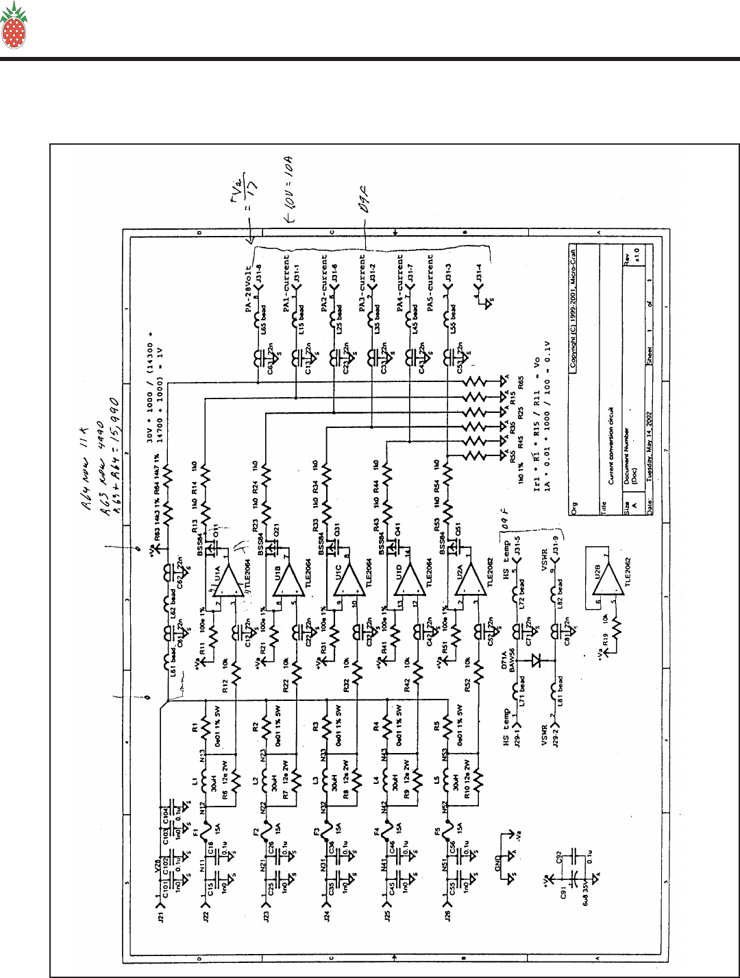
2. 1A0025 Power Distribution Monitor

PINEAPPLE TECHNOLOGY, INC.
UTX5KW-A Operating and Service Manual VI — SCHEMATICS AND PARTS LIST
Page 31
VI — SCHEMATICS AND PARTS LIST
E. U600LDV-2
2. 1A0025 — Parts List
Item Qty Type P/N Title Detail Ref(m)
Printed 8/16/2004
DC ISO/MONITOR CKT
REPLACED CB99
Type
Status
Revision
PL
U
B
User1
User2
User3
User4
User5
Date
By
11/29/2001
RA
1A0025Top PL DC ISO/MONITOR CKT REPLACED CB99
PC9050C11PS PCB DC ISO/MONT
BRD FR4 060
5601012 1 PS OP-AMP QUAD PAK TLE2064AID TI U1
5601023 1 PS OP-AMP DUAL PAK 8-SOIC U2
27022N4 21 PS FT CAP 22N SM AVX OR MURRATA
PART C11, 12,
13, 21, 22,
23, 31, 32,
33, 41, 42,
43, 51, 52,
53, 61, 63,
71, 73, 81,
83
2401025 1 PS CAP SM TAN 6.8 UF 35 V C CASE C91
21Y0226 1 PS CAP SM 1206 47 NF 50 V C92
4720157 5 PS FUSE PICO II EPOXY 15 A 32 VDC F1, 2, 3, 4,
5
48125081PS CON DB9 SUB RT
ANGLE FM METAL CASE
AMP7457814 J31
1A00119 5 PL TOROID IND 10 T #14 ON N40 L1, 2, 3, 4,
5
59001010 5 PS XISTOR FET BSS84 BSS84ZXCT Q11, 21,
31, 41, 51
150R0111 5 PS RES 5 WATT AXIAL 0.01 OHM 1.0 % R1, 2, 3, 4,
5
14001012 5 PS RES AXIAL 2 W 10 OHM R6, 7, 8, 9,
10
115100013 5 PS RES CHIP 0805 100 OHM 1% 0805 R11, 21,
31, 41,51
115100214 6 PS RES CHIP 0805 10 K OHM 1% 0805
CASE R12, 19,
22, 32, 42,
52
115100115 10 PS RES CHIP 0805 1 K OHM 1 % R13, 14,
15, 23, 24,
25, 33, 34,
35, 43, 44,
45, 53, 54,
55, 65
45107017 5 PS HW PWR TAP 6-32 STL KEYSTONE
8191 J22, 23, 24,
25, 26
48030018 1 PS CON 2 PIN HEADER AMP A23837-ND P29
48031019 1 PS CON 2 PIN PC POST AMP 640456-2 J29
PINEAPPLE TECHNOLOGY, INC.
4021 ALVIS COURT, #6, ROCKLIN, CA 95677
916-315-8338 Fax 916-315-8118
1A0025
2Page 1 o
f

PINEAPPLE TECHNOLOGY, INC.
UTX5KW-A Operating and Service Manual
Page 32
VI — SCHEMATICS AND PARTS LIST
VI — SCHEMATICS AND PARTS LIST
E. U600LDV-2
2. 1A0025 — Parts List (Cont.)
75000120 12 PS FERRITE BEAD SMT 0805 EMI FERRITE
BEAD L15,25,35,4
5,55,61,62,
65,71,72,81
,82
21X00521 9 PS CAP CHIP 0805 100NF 10% XTR 0805
CASE C16,26,36,
46,56,102,1
04,106,108
21X00622 9 PS CHIP CAP 0805 1000 PF 10% 0805
CASE C15,25,35,
45,55,101,1
03,105,107
115499123 1 PS RES CHIP 0805 4.99K OHM 1% 0805
CASE R63
11511324 1 PS RES CHIP 0805 11K OHM 1% 0805
CASE R64
52026025 1 PS DIODE SWITCH 80V 100MA MINI 3P
Item Qty Type P/N Title Detail Ref(m)
1A0025
Printed 8/16/2004
Rev B
DC ISO/MONITOR CKT
REPLACED CB99
PINEAPPLE TECHNOLOGY, INC.
4021 ALVIS COURT, #6, ROCKLIN, CA 95677
916-315-8338 Fax 916-315-8118
1A0025
2Page 2 o
f
PINEAPPLE TECHNOLOGY, INC.
UTX5KW-A Operating and Service Manual VI — SCHEMATICS AND PARTS LIST
Page 33
VI — SCHEMATICS AND PARTS LIST
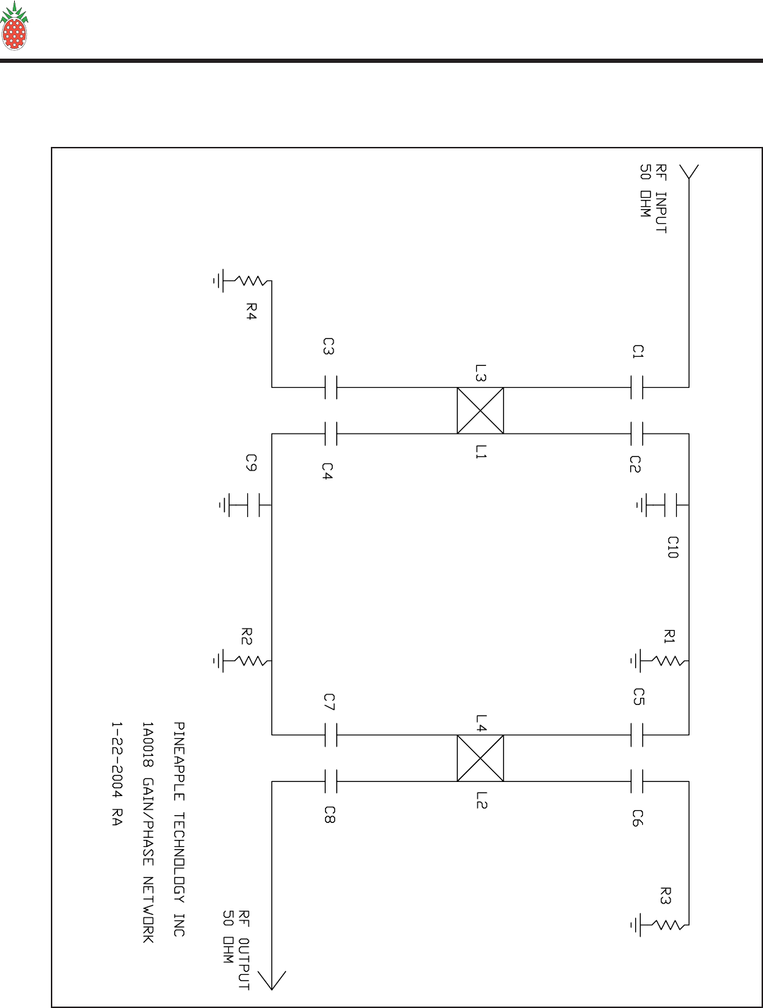
E. U600LDV-2
3. 1A0018 Gain and Phase Matching

PINEAPPLE TECHNOLOGY, INC.
UTX5KW-A Operating and Service Manual
Page 34
VI — SCHEMATICS AND PARTS LIST
VI — SCHEMATICS AND PARTS LIST
E. U600LDV-2
3. 1A0018 — Parts List
Item Qty Type P/N Title Detail Ref(m)
Printed 8/16/2004
PHASE & GAIN MATCHING UHF
U500/U600LD ASS'Y
Type
Status
Revision
PL
U
A
User1
User2
User3
User4
User5
Date
By
1/14/2001
RA
1A0018Top PL PHASE & GAIN
MATCHING UHF U500/U600LD ASS'Y
PC9031A1 2 PS PCB BB QUAD 4 LAYER RGR 4003
008/060
8225602 4 PS IND CHIP 56 NH 0805 SM L1,2,3,4
2633903 8 PS CAP CHIP 39 PF B CASE ATC C1,2,3,4,5,
6,7,8
2631004 2 PS CAP CHIP ATC 10 PF B CASE C9,10
DIRECT_LABOR5.1PS LABOR INHOUSE
LABOR/TEST
180010-50T6 2 PS RES PWR 10 W 50 OHM TERM R3,4
11Y6817 2 PS RES CHIP 1 W 680 OHM 2512 CASE
SMT R1,2
PINEAPPLE TECHNOLOGY, INC.
4021 ALVIS COURT, #6, ROCKLIN, CA 95677
916-315-8338 Fax 916-315-8118
1A0018
1Page 1 o
f

PINEAPPLE TECHNOLOGY, INC.
UTX5KW-A Operating and Service Manual
Page 35
VI — SCHEMATICS AND PARTS LIST
VI — SCHEMATICS AND PARTS LIST
F. SPLITTER S10-10 IN PHASE SPLITTER — Parts List
Item Qty Type P/N Title Detail Ref(m)
Printed 9/7/2004
SPLITTER HOUSING UPTO 10 -WAY
MULTI-USE 10-WAY BNC I/O
Type
Status
Revision
CAT
U
A
User1
User2
User3
User4
User5
Date
By
6/7/2004
RA
S10Top CAT SPLITTER HOUSING
UPTO 10 -WAY MULTI-USE 10-WAY
BNC I/O
MF9333A11PS FRONT PANEL S10
SPLITTER PAINTED
MF9334A3 1 PS S10 TOP COVER AL 0.063 THK GOLD
ALODYNE
MF9335A4 1 PS CHASSIS S10
MF9336A5 1 PS REAR CONN PANEL S10
PINEAPPLE TECHNOLOGY, INC.
4021 ALVIS COURT, #6, ROCKLIN, CA 95677
916-315-8338 Fax 916-315-8118
S10
1Page 1 o
f

PINEAPPLE TECHNOLOGY, INC.
UTX5KW-A Operating and Service Manual
VI — SCHEMATICS AND PARTS LIST
G. COMBINER UC5KW-DC40 — Parts List
VI — SCHEMATICS AND PARTS LIST
Page 36
No servicable parts.
PINEAPPLE TECHNOLOGY, INC.
UTX5KW-A Operating and Service Manual
VI — SCHEMATICS AND PARTS LIST
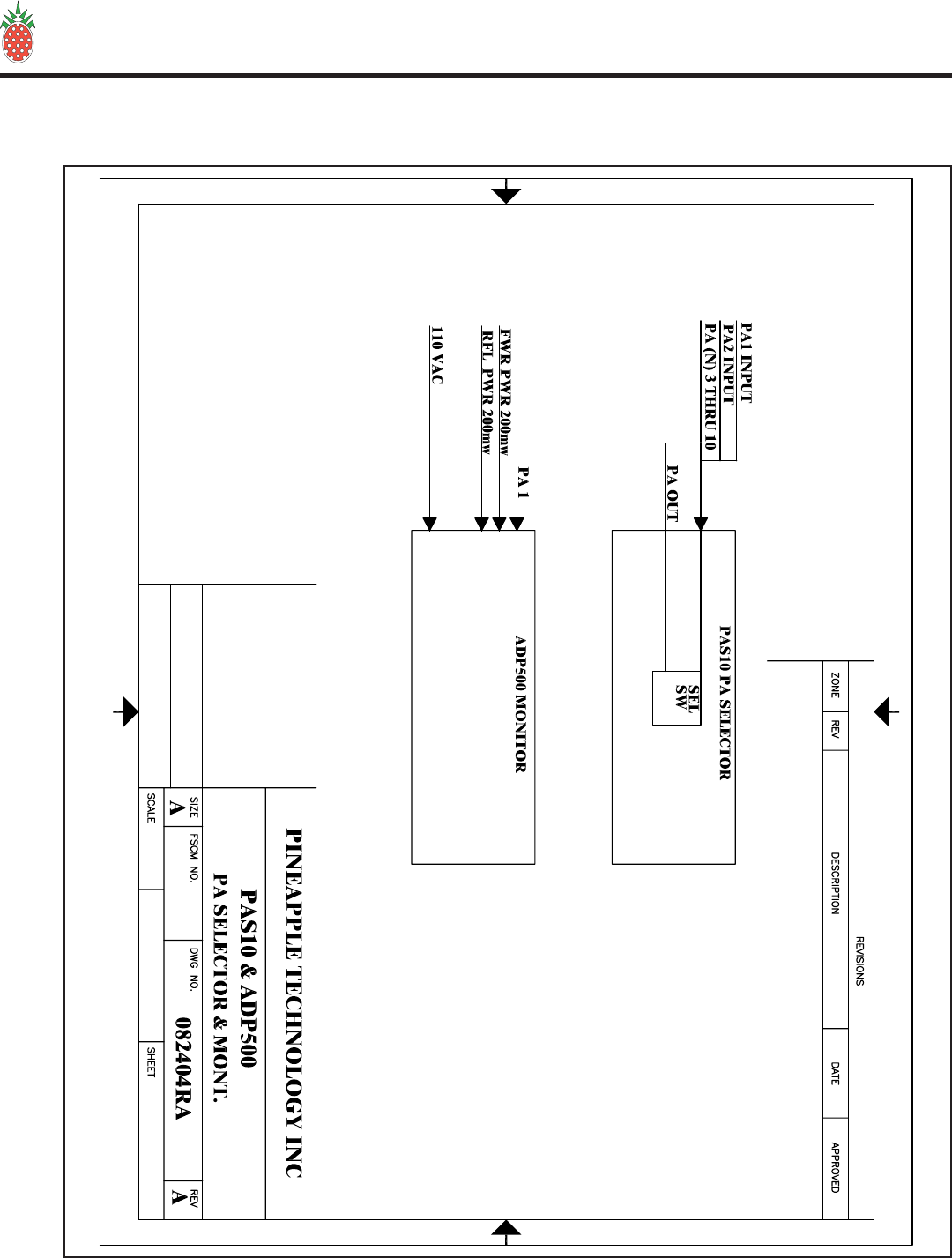
H. PAS10 & ADP500 MONITOR
Page 37
VI — SCHEMATICS AND PARTS LIST

PINEAPPLE TECHNOLOGY, INC.
UTX5KW-A Operating and Service Manual
VI — SCHEMATICS AND PARTS LIST
H. PAS10 MONITOR — Parts List
Item Qty Type P/N Title Detail Ref(m)
Printed 9/7/2004
PA SEL SW FOR ADP500
10 POLE INPUT 1 OUTPUT
Type
Status
Revision
CAT
U
A
User1
User2
User3
User4
User5
Date
By
6/22/2004
RA
PAS10Top CAT PA SEL SW FOR
ADP500 10 POLE INPUT 1
OUTPUT
PC950111PS PA SELECTER
SWITCH 10 POLE ADP500
4830102 1 PS SW 10 POLE ADP500 PA
SELECTOR PAS10
48125031PS CON DB9 SUB RT
ANGLE FM METAL CASE
AMP7457814
48126045PS CON DB9 2 SECTION
RT ANG PCB MTG 0.9
SPACING
MF9342X15 1 PS PLATE, FRONT PAS10 W/ PAINT &
SILKSCREEN
MF9343X16 1 PS CHASSIS, PAS10 W/ ALODINE &
SILKSCREEN
MF9344X17 1 PS COVER, TOP PAS10 W/ ALODINE &
SILKSCREEN
PINEAPPLE TECHNOLOGY, INC.
4021 ALVIS COURT, #6, ROCKLIN, CA 95677
916-315-8338 Fax 916-315-8118
PAS10
1Page 1 o
f
Page 38
PINEAPPLE TECHNOLOGY, INC.
UTX5KW-A Operating and Service Manual
VI — SCHEMATICS AND PARTS LIST
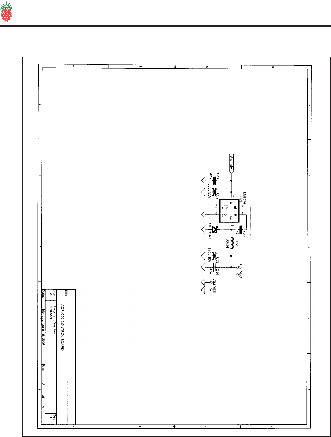
H. ADP500 MONITOR
Page 39
PINEAPPLE TECHNOLOGY, INC.
UTX5KW-A Operating and Service Manual VI — SCHEMATICS AND PARTS LISTS
Page 40
PINEAPPLE TECHNOLOGY, INC.
UTX5KW-A Operating and Service Manual VI — SCHEMATICS AND PARTS LISTS
Page 41
PINEAPPLE TECHNOLOGY, INC.
UTX5KW-A Operating and Service Manual
Page 42
VI — SCHEMATICS AND PARTS LISTS

PINEAPPLE TECHNOLOGY, INC.
UTX5KW-A Operating and Service Manual
Item Qty Type P/N Title Detail Ref(m)
Printed 9/7/2004
DISPLAY PANEL, ANALOG
SEL SW AND METER
Type
Status
Revision
CAT
U
A
User1
User2
User3
User4
User5
Date
By
9/15/2002
RA
ADP500Top CAT DISPLAY PANEL,
ANALOG SEL SW AND METER
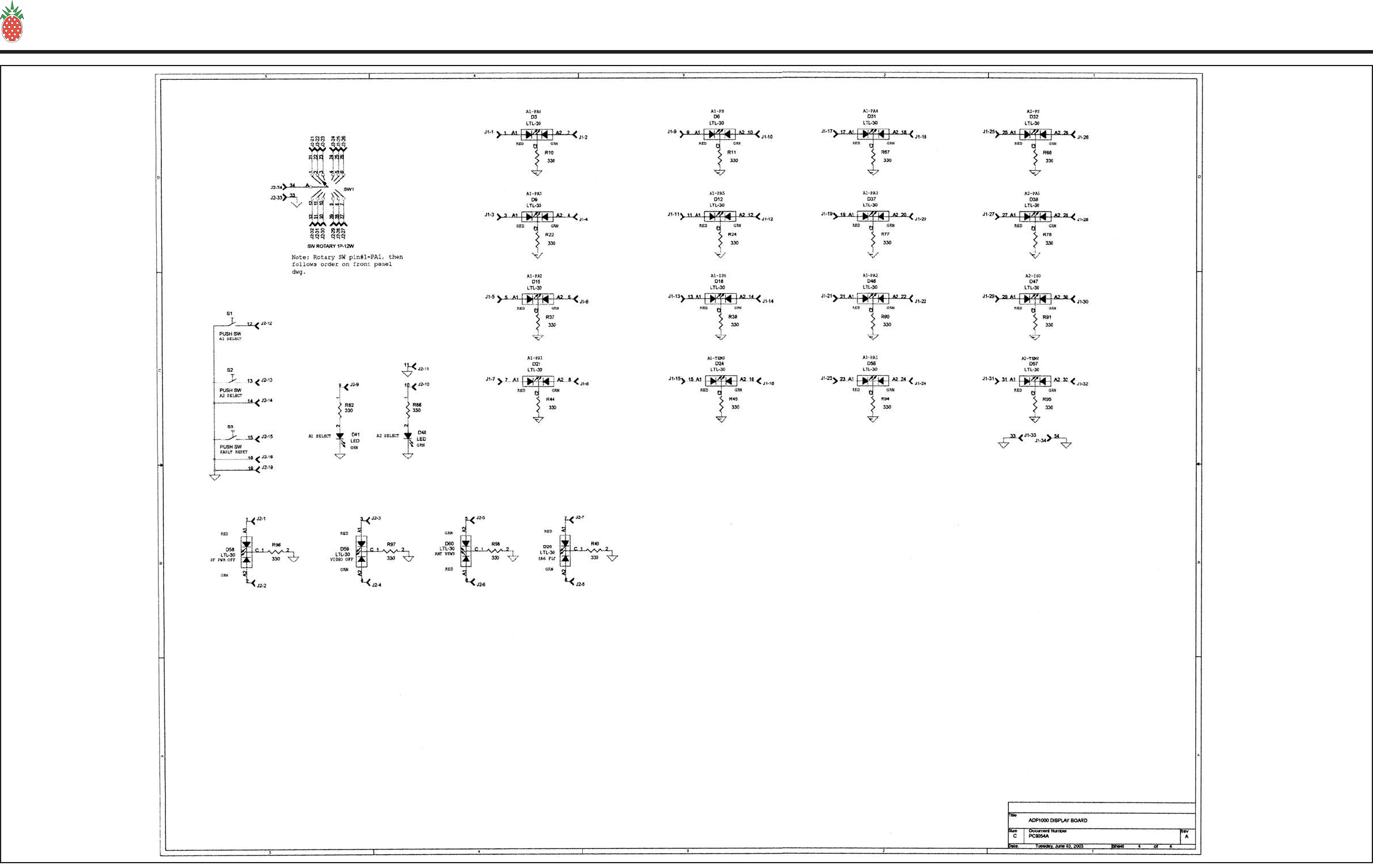
1A00291 1 PL ADP1000 LOGIC PCB LOGIC BRD PARTS
1A00302 1 PL ADP1000 FP PCB FP PCB AND PARTS
4713063 1 PS FUSE 3AG 6 AMP
46015041PS FUSE HOLDER PANEL
MTG 3AG TYPE QC CON
48400151PS SW, ON/OFF ROCKER
AC CW IND.
NAA-211-B121-00
6601036 1 PS METER, 2 VOLTS FS SELCO 39M-0-2VDC
1A00277 1 PL PWR MONITOR CK PC9052B CBR
PS252781PS POWER SUPPLY
OPEN/FRAME 110/220 VAC 27 V 25
W
PINEAPPLE TECHNOLOGY, INC.
4021 ALVIS COURT, #6, ROCKLIN, CA 95677
916-315-8338 Fax 916-315-8118
ADP500
1Page 1 o
f
VI — SCHEMATICS AND PARTS LIST
H. ADP500 MONITOR — Parts List
Page 43

PINEAPPLE TECHNOLOGY, INC.
UTX5KW-A Operating and Service Manual
Page 44
VI — SCHEMATICS AND PARTS LIST
H. ADP500 MONITOR
1. 1A0027 — Parts List
Item Qty Type P/N Title Detail Ref(m)
Printed 8/16/2004
PWR MONITOR CK
PC9052B CBR
Type
Status
Revision
PL
U
B
User1
User2
User3
User4
User5
Date
By
12/15/2001
RA
1A0027Top PL PWR MONITOR CK PC9052B CBR
PC9052B1 1 PS PWR MONITOR BRD FR4 060 1/1 2 SIDES
CBR CKTS PC BOARD
1151032 3 PS RES CHIP 0805 10K OHM SMT 0805 R9, 33
5601083 2 PS SEMI OP-AMP DUAL OP AMP U1, 2
1152716 1 PS RES CHIP 0805 270 OHM 0805 R28
1152727 1 PS RES CHIP 0805 2.7K OHM 0805 CASE R23, 24,
26, 27
1152738 1 PS RES CHIP 0805 27K OHM 0805 CASE R8
11510210 6 PS RES CHIP 0805 1K OHM 0805 CASE R5, 7, 31,
45
11510411 5 PS RES CHIP 0805 100K OHM 0805 SMT R4, 6, 29,
30, 44
11510512 3 PS RES CHIP 0805 1M OHM 0805 CASE
SMT R3, 22, 43
11500013 3 PS RES CHIP 0805 0 OHM 0805 CASE
SMT R2, 42, 21
11Y51014 2 PS RES CHIP 1W 51 OHM 5% 2512
CASE R1, 41
52030015 1 PS SEMI GP XSTR MMBT2222ALT1 Q1, Q2
52020116 3 PS SEMI DIODE SHOTKEY 70V Surf Mnt D1, 2, 3
822560-WW17 2 PS IND CHIP W/W 56 NH WW HI-Q OSC
CKT L1, 2
48500119 1 PS HEADER 10 PIN TH AMP 0.1 CTR
103308-1 J3
21Y00120 2 PS CHIP CAP 1206 39 PF 50 V NPO C1, 41
21X00721 14 PS CHIP CAP 0805 47NF 50WVDC X7R C3, 21, 23,
24, 26, 27,
29, 43, 51,
52, 53, 55,
56
21Y00423 2 PS CHIP CAP 1206 2.2 NF 50V NPO C22, 25
24010524 2 PS CAP SM CASE C 10 UF 10 V TAN C54, 57
17M10225 3 PS RES VARI 12 TURN 1K OHMS SM R10, 34, 47
17M10326 1 PS RES VARI 12 TURN 10K OHMS SM R32
11515127 1 PS RES CHIP 0805 150 OHM 1% 0805
SMT R25
11593128 1 PS RES CHIP 0805 930 OHM 1% 0805
SMT R46
24010629 2 PS CAP SM CASE 1206 2.2 UF 16V TAN C2, 42
PINEAPPLE TECHNOLOGY, INC.
4021 ALVIS COURT, #6, ROCKLIN, CA 95677
916-315-8338 Fax 916-315-8118
1A0027
2Page 1 o
f

PINEAPPLE TECHNOLOGY, INC.
UTX5KW-A Operating and Service Manual
Page 45
VI — SCHEMATICS AND PARTS LIST
H. ADP500 MONITOR
1. 1A0027 — Parts List (Cont.)
24010730 1 PS CAP SM 1206 CASE 4.7UF 16 V TAN 1206
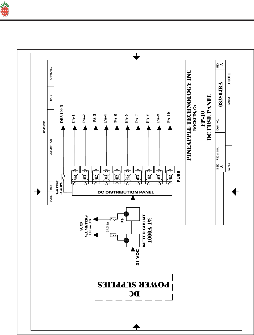
CASE C28
11536231 1 PS RES CHIP 0805 3.6K OHM 0805 SMT R11
99630032 2 PS INDUCTOR 1T +
TORROID #22 SOLID WIRE AND
TORROID L5, 6
Item Qty Type P/N Title Detail Ref(m)
1A0027
Printed 8/16/2004
Rev B
PWR MONITOR CK
PC9052B CBR
PINEAPPLE TECHNOLOGY, INC.
4021 ALVIS COURT, #6, ROCKLIN, CA 95677
916-315-8338 Fax 916-315-8118
1A0027
2Page 2 o
f

PINEAPPLE TECHNOLOGY, INC.
UTX5KW-A Operating and Service Manual
Page 46
VI — SCHEMATICS AND PARTS LIST
H. ADP500 MONITOR
2. 1A0029 — Parts List
Item Qty Type P/N Title Detail Ref(m)
Printed 8/16/2004
ADP1000 LOGIC PCB
LOGIC BRD PARTS
Type
Status
Revision
PL
U
A
User1
User2
User3
User4
User5
Date
By
1/5/2002
RA
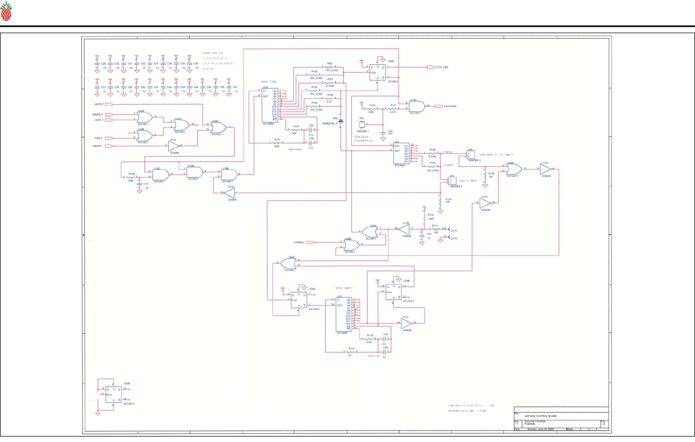
1A0029Top PL ADP1000 LOGIC PCB LOGIC BRD PARTS
PC905511PS ADP1000 LOGIC
BOARD FR4 060 1/1 CBR
5603202 2 PS LOGIC IC MC14013 DUAL D F/F SOT 14 U20, 24
5603153 3 PS LOGIC IC MC14011BD LOG CMOS GATE
NAND QUAD U8, 10, 18
56032545PS LOGIC IC MC14042BD
16 PIN LOG CMOS LATCH
QUAD TRAN U5, 7, 11, 13,
15
5603105 2 PS LOGIC IC MC14060BD CTR/DRIVER IC SOT
16 U19, 23
5391006 2 PS IC HEX INV BUFFER CD4049UBCM U9, 17
5603307 2 PS LOGIC IC MC14071BD LOG CMOS GATE OR
QUAD SO14 U16, 22
5390008 4 PS IC DIF AMP QUAD LM339DR SO14 U4, 6, 12, 14
5601089 1 PS SEMI OP-AMP DUAL OP AMP U3
56250010 2 PS ANALOG MC14551BD MUX/DE-MUX 2
CHANNEL U1, U2
53810011 1 PS IC SWITCHER/REG
LM2674M-5.0 28 V IN 5 VOLTS OUT
500MA U51
53911012 1 PS LOGIC IC CD4024BM 7 STAGE COUNTER
SO14 U21
11622R1313 2 PS RES CHIP 1206 22.1K OHM SMT R7, 64
115511214 4 PS RES 0805 CASE 51.1 K OHM 1% R36, 41, 89,
93
115324215 1 PS RES 0805 CASE 32.4 K OHM 1% R52
52030016 2 PS SEMI GP XSTR MMBT2222ALT1 Q1, Q2
52027217 42 PS DIODE HEX FET P HEX FET SOT-3 D1, 2, 4, 5, 7,
8, 10, 11, 13,
14, 16, 17, 19,
20, 22, 23, 25,
27, 28, 29, 30,
33, 34, 35, 36,
39, 40, 42, 43,
44, 45, 49, 50,
51, 52, 53, 54,
55, 61, 62, 63,
64
83051018 1 PS IND, W/W 82 UH .58A PWR SMD L51
52012919 4 PS SEMI DIODE GP 1N914 SM SOT-23 D65, 66, 67,
68, 92
PINEAPPLE TECHNOLOGY, INC.
4021 ALVIS COURT, #6, ROCKLIN, CA 95677
916-315-8338 Fax 916-315-8118
1A0029
3Page 1 o
f

PINEAPPLE TECHNOLOGY, INC.
UTX5KW-A Operating and Service Manual
Page 47
VI — SCHEMATICS AND PARTS LIST
H. ADP500 MONITOR
2. 1A0029 — Parts List (Cont.)
11610521 17 PS RES CHIP 1/8 W 1 M OHM SM 1206 R1, 4, 9, 12,
18, 19, 23, 29,
46, 53, 61, 66,
70, 75, 79, 84,
119
11610322 27 PS RES CHIP 1/8 W 10 K OHM SM 1206 R2, 5, 6, 13,
20, 21, 27, 30,
43, 47, 54, 57,
59, 62, 63, 71,
76, 81, 85,
114, 115, 116,
117, 122, 128,
130, 131
11610223 14 PS RES CHIP 1/8 1 K OHM SM 1206 R3, 8, 14, 25,
26, 28, 34, 35,
40, 48, 51, 55,
65, 72, 80, 83,
87,88, 92, 125
21Y04224 36 PS CAP CHIP 0.1 UF 50 V 1206 C1,2,20,21,22,
23,26, 27, 29,
30, 31,31.33,
34, 35. 36, 37,
38, 39, 40, 41,
42, 43, 44, 45,
46, 47, 49, 50,
74, 76, 77, 78,
79, 80, 81,
27022N25 18 PS FT CAP 22N SM AVX OR MURRATA
PART C3, 4, 5, 7, 8,
9, 10, 11, 12,
13, 14, 15, 16,
17, 18, 19, 71,
72
75000126 18 PS FERRITE BEAD SMT 0805 EMI FERRITE
BEAD F1, 2, 5, 4, 5,
7, 8, 9, 10, 11,
12, 13, 14, 15,
16, 17
24131027 1 PS CAP RADIAL TH 680 UF 35 WVDC AL
ELECTROLYTIC C52
24132028 1 PS CAP RADIAL TH 1200 UF 10 WVDC AL
ELECTROLYTIC C53
24020029 1 PS CAP SM 1206 CASE 10 UF 10 WVDC C24
21Y04130 4 PS CAP CHIP 0.01 UF SM 1206 C25, 48, 73,
75
21Y02231 3 PS CAP SM 1206 47 NF 50 V C51, 54, 55
116332132 1 PS RES CHIP 1206 3.32 K OHM 1% R135
116225233 1 PS RES CHIP 1206 25.5K OHM 1206
CASE R121
11647434 1 PS RES CHIP 1206 470K OHM 1/8 W R118
11612435 1 PS RES CHIP 1206 CASE 120 K OHM 5% R107
11656336 1 PS RES CHIP 1206 CASE 56K OHM 5% R106
11622437 1 PS CHIP RES 1206 220 K OHM 1206
CASE 5% R105
Item Qty Type P/N Title Detail Ref(m)
1A0029
Printed 8/16/2004
Rev A
ADP1000 LOGIC PCB
LOGIC BRD PARTS
PINEAPPLE TECHNOLOGY, INC.
4021 ALVIS COURT, #6, ROCKLIN, CA 95677
916-315-8338 Fax 916-315-8118
1A0029
3Page 2 o
f

PINEAPPLE TECHNOLOGY, INC.
UTX5KW-A Operating and Service Manual
Page 48
VI — SCHEMATICS AND PARTS LIST
H. ADP500 MONITOR
2. 1A0029 — Parts List (Cont.)
11600038 3 PS RES CHIP 1206 0.0 OHMS SM R101, 108,
112
116XXX39 7 PS CHIP RES 1206 +++NO LOAD+++ R99, 100, 102,
104, 109, 113,
120
11610140 3 PS RES CHIP 1/8 W 100 OHM SM 1206 R60, 69, 111
11622341 2 PS RES CHIP 1/8 W 22 K OHM SM 1206 R58, 136
11610042 2 PS RES CHIP 1/8 W 10 OHM SM 1206 R39, 50
116301143 3 PS RES CHIP 1206 3.01K OHM 1206
CASE R17, 74, 127
11647244 4 PS RES CHIP 1206 4.7K OHM 1/8 W SMT R42, 56, 103,
123
11639245 1 PS RES CHIP 1/8 W 3.9 K OHM SM 1206 R33
11616246 4 PS RES CHIP 1206 1.6K OHM 5% 1206
CASE R16, 73, 124,
134
11610447 6 PS RES CHIP 1/8 W 100 K OHM SM 1206 R15, 110, 126,
129, 132, 133
17L102XT48 1 PS RES VAR 12 TURN 1K SMT POT 12 TURN R32
48060049 2 PS CON HEADER 0.1
CTRS PROTECTED
HEADER 34 PIN J1, J2
48500150 1 PS HEADER 10 PIN TH AMP 0.1 CTR
103308-1 J79
48031051 2 PS CON 2 PIN PC POST AMP 640456-2 JP1, 7, 8, 9
48032052 1 PS CON 4 PIN PC
LOCKING POST MOLES MALE JP5
52021253 1 PS SEMI DIODE SHOTKEY 40V 1A D91
48125054 3 PS CON DB9 SUB RT
ANGLE FM METAL CASE
AMP7457814 J3, 4, 6
Item Qty Type P/N Title Detail Ref(m)
1A0029
Printed 8/16/2004
Rev A
ADP1000 LOGIC PCB
LOGIC BRD PARTS
PINEAPPLE TECHNOLOGY, INC.
4021 ALVIS COURT, #6, ROCKLIN, CA 95677
916-315-8338 Fax 916-315-8118
1A0029
3Page 3 o
f

PINEAPPLE TECHNOLOGY, INC.
UTX5KW-A Operating and Service Manual
Page 49
VI — SCHEMATICS AND PARTS LIST
H. ADP500 MONITOR
3. 1A0030 — Parts List
Item Qty Type P/N Title Detail Ref(m)
Printed 8/16/2004
ADP1000 FP PCB
FP PCB AND PARTS
Type
Status
Revision
PL
U
A
User1
User2
User3
User4
User5
Date
By
1/5/2002
RA
1A0030Top PL ADP1000 FP PCB FP PCB AND PARTS
PC9054A11PS ADP1000 DISPLAY
BRD FR4 060 1/1 CRB
4830012 1 PS SW, 12 POS ROTOR SIG SEL SW ADP1000 SW1
4840503 3 PS SW, MOMENTARY PB OMRON B3WN-6002 S1, 2, 3
1503304 22 PS RES 1/4W AXIAL TH 1.4 W 330 OHM TH
AXIAL R10, 11, 22,
24, 37, 38, 44,
45, 49, 67, 68,
77, 78, 82, 86,
90, 91, 94, 95,
96, 97, 98
6302005 22 PS IND LED DUAL COLOR RED/GREEN T1-3/4
CLR D3, 6, 9, 12,
15, 18, 21, 24,
26, 31, 32, 37,
38, 46, 47, 56,
57, 58, 59, 60,
48, 41
48060062PS CON HEADER 0.1
CTRS PROTECTED
HEADER 34 PIN J1, 2
PINEAPPLE TECHNOLOGY, INC.
4021 ALVIS COURT, #6, ROCKLIN, CA 95677
916-315-8338 Fax 916-315-8118
1A0030
1Page 1 o
f

PINEAPPLE TECHNOLOGY, INC.
UTX5KW-A Operating and Service Manual
VI — SCHEMATICS AND PARTS LIST
I. AUX5 MONITOR PANEL — Parts List (cont.)
Page 50
Item Qty Type P/N Title Detail
Printed 9/20/2004
AUX PANEL 5KW
USED ON 3, 4, 5 KW XMTRS
Type
Status
Revision
CAT
U
A
User1
User2
User3
User4
User5
Date
By
6/7/2004
RA
AUX5KTop CAT AUX PANEL 5KW USED ON 3, 4, 5 KW XMTRS
48401021PS SW, EMERGENCY
SHUTDOWN NO/NC RESETABLE
AC42003 1 PS AC DUPLEX OUTLET 110 VAC 15 A BLACK
66011041PS DC PANEL METER 50
V FS HOYT MODEL 3115 1-1/2 ANA
PANEL
66011451PS DC AMP METER 500 A
FS HOYT 3115 100mv FS
AC51016 1 PS AC PANEL MT 15 AMP 3 PIN SCW MTG
4530007 3 PS HW, TIP JACK RED, Insulated standard TIP JACK
4530018 3 PS HW TIP JACK WHITE, Insulated standard TIP
JACK
4530029 1 PS HW, TIP JACK BLACK, Insulated standard TIP
JACK
45300310 3 PS HW, TIP JACK BLUE, Insulated Standard TIP JACK
48110011 3 PS CON 9 P D-SUB MALE MALE 9P SOLDER CUP
48120012 3 PS CON 9P D-SUB FEMAL DB9P SOLDER CUP
63000213 1 PS INDICATOR LITE GREEN 120 VAC
MF9330A14 1 PS CURRENT MONITOR,
REAR PANEL SHUNT AND FUSE MTG PLATE
MF9332B15 1 PS CHASSIS AUX5 REAR SILK AND ALODYNE
48046516 1 PS MOLEX PLUG
HOUSING 9 POLE MATE-LOC
48046617 1 PS MOLEX CAP HOUSING 9 POLE
48046718 1 PS MOLEX STRAIN
RELIEFS 9 POLE
48046819 3 PS MOLEX SOCKET
CONTACTS CONN SOCKET 18-24 AWG TIN
CRIMP
48046920 3 PS MOLEX PIN
CONTACTS CONN PIN 18-24 AWG TIN CRIMP
48047021 1 PS MOLEX PLUG STR 3
PIN MOLEX 39-01-4032-P
48047122 1 PS MOLEX RECEPTACLE
HSN 3 PIN MOLEX 39-01-4030
46015025 1 PS FUSE HOLDER PANEL
MTG 3AG TYPE QC CON
48047226 1 PS MOLEX CRIMP TERM
MFA1KW MOLEX MFG 39-00-0041
48047327 1 PS MOLEX CRIMP
TERMINAL U600LD MOLEX 39-00-0039 FEMALE
PINEAPPLE TECHNOLOGY, INC.
4021 ALVIS COURT, #6, ROCKLIN, CA 95677
916-315-8338 Fax 916-315-8118
AUX5
K
1Page 1 o
f
PINEAPPLE TECHNOLOGY, INC.
UTX5KW-A Operating and Service Manual
Page 51
SECTION IV — PS2KW
VI — SCHEMATICS AND PARTS LIST
J. FP-10 FUSE PANEL

PINEAPPLE TECHNOLOGY, INC.
UTX5KW-A Operating and Service Manual
VI — SCHEMATICS AND PARTS LIST
J. FP10 FUSE & SHUNT PANEL — Parts List
Page 52
Item Qty Type P/N Title Detail
Printed 9/20/2004
FUSE PANEL UTX5KWA
INC FUSES, SHUNT, AND COVER SHIELD
Type
Status
Revision
CAT
U
A
User1
User2
User3
User4
User5
Date
By
9/1/2004
RA
FP-10Top CAT FUSE PANEL
UTX5KWA INC FUSES, SHUNT, AND COVER
SHIELD
4601901 10 PS FUSE HOLDER 400A LITTELFUSE LFFB0001
471380210PS FUSE FAST ACTING 80
AMP USE WITH LFFB0001 HOLDER
6710003 1 PS SHUNT 1000 Amps, 100mV
PINEAPPLE TECHNOLOGY, INC.
4021 ALVIS COURT, #6, ROCKLIN, CA 95677
916-315-8338 Fax 916-315-8118
FP-10
1Page 1 o
f

PINEAPPLE TECHNOLOGY, INC.
UTX5KW-A Operating and Service Manual
Page 53
VII — ROUTINE MAINTENANCE
VII — ROUTINE MAINTENANCE
The following KEY MAINTENANCE AND PERFORMANCE CHECKS should be made monthly or more
frequently in some environment where dust is a problem:
TRANSMITTER
• Remove and clean the air lters with a light detergent and DRY COMPLETELY before re-installing. Dirty
lters will cause PA amps to shutdown resulting in a loss of RF power. Spare lter P/N 990199 is available
from Pineapple Technology, Inc.
• Check and record the Voltage and Current meter readings on the ACDIS5 (AC AND DC DISTRIBUTION
UNIT LOCATED NEAR THE POWER SUPPLIES). NOTE: current readings will vary with picture content,
therefore, a standard video waveform such as SMPTE BARS should be used.
• Using the ADP500 & PAS10 — record the bias level settings on each PA Pallet by selecting the appropriate PA
with the selector switch. To make this measurement of BIAS ONLY it is necessary to activate the PA INHIBIT
switch momentarily for each reading.
• Using the ADP500 — check and record the RF Output power level to ensure that it is still reading 100% +/-
10% from the previous settings.
• Using the ADP500 — check and record the VSWR (Reected power) to ensure that it is still reading only a
few percent indicating normal load operations.
• Using the ADP500 — check and record Aural power readings. This is normally set between 5 and 10% of
P-sync. Expect this to vary only a few percent from reading to reading.
• Carefully inspect RF Output coax and coaxial ttings for excessive heating or discoloration.
• Check power supply, shunt, fuse, and PA DC Connections for any signs of over heating or loose hardware.
• Check output combiner and BP lter for any signs of over heating.
FACILITIES
• Clean all air inlet lters and exhaust outlets to ensure that the transmitter is getting clean unobstructed air ow.
• Perform recommended service on air condition systems.
• Rodent traps or baits should be renewed to keep the facilities clear of these pests which can cause damage
to the transmitter.

PINEAPPLE TECHNOLOGY, INC.
UTX5KW-A Operating and Service Manual
Page 54
VIII — ADJUSTMENTS AND TUNING
VIII — ADJUSTMENTS AND TUNING
The UTX5KW-A is basically an FCC Type Certied broadband transmitter with a few frequency selective
sub-assemblies. A list of these sub-assemblies are listed below and followed by general instructions where
applicable:
A. MODULATOR/UPCONVERTER — Instructions for making adjustments to the modulator are
included in the manufacturer’s instruction manual.
B. BPU5KW Band Pass Filter comes adjusted to the channel as purchased. To change frequency would
require a tuning adjustment to the lter. To perform this adjustment it is necessary to use a NETWORK
ANALYZER and a signal generator with necessary I/O Adaptors to connect to the lter. The Technician
performing this adjustment should be skilled in tuning Band Pass Filters. If the target frequency is
outside of the tuning range of the lter, it becomes necessary to purchase a new lter. Replacement
lters and service is available from Pineapple Technology, Inc.
C. U600LDV-2 POWER AMPLIFIER MODULE — The U600LDV-2 has three areas where adjust-
ments may be necessary over time or in the event of a frequency change. These areas are:
1. Bias adjustments: The LDMOS FET devices used in these pallet ampliers are set to 500ma/device
side or a total of 1 amp/device. This adjustment can be made on the bench by rst terminating the
input and output with 50 ohm terminations. Apply 31 volts DC to the PA using a power supply that
can provide a minimum of 15 amps. Note: a cooling fan will be necessary to cool the amplier
during this adjustment.
To adjust the bias’ it is best to turn all the bias adjust resistors CCW or to minimum on the pallet
being adjusted. Using a clamp on AMP Meter connected to the DC Feed terminal located on the DC
ISOLATION AND CURRENT MONITOR BOARD measure the current levels. The rst resistor is
increased to 500ma indicated on the Amp meter. Repeat this adjustment for each additional resistor
for reading of 1.0 A, 1.5 A, and 2.0 A. This will indicate that each device half is set to 500 ma.
This concludes the bias adjustment procedure. This adjustment should be made at any time when
a device has to be replaced. Normal bias ranges from 1.5 amps to 2.3 amps per pallet as indicated
on the ADP500/1000. DO NOT USE THE ADP500/1000 CURRENT READINGS FOR MAKING
BIAS ADJUSTMENTS.
2. PA PALLET RF circuit tuning: These circuits are broadband and xed tuned providing no adjust-
ments. Any tuning at this level is performed by the factory.
3. GAIN & PHASE MATCHING: Each U600LDV-2 comes with a circuit for making Gain and Phase
adjustments. This adjustment is xed tuned for the channel of this transmitter. Adjustment to this
circuit requires the following equipment:
• HP 8508A VECTOR VOLTMETER
• BIRD THRU LINE WATT METER
• SPLITTER
• 2ea DIRECTIONAL COUPLERS
• 2ea 500 watt terminations
• Component selection charts for resistors
• Component selection chart for capacitors
Component selection charts and setup block diagram provided as needed. Recommended tuning should be
within +/- 0.15 dB and +/- 3 degrees as measured on the HP 8508A.

PINEAPPLE TECHNOLOGY, INC.
UTX5KW-A Operating and Service Manual
Page 55
VIII — ADJUSTMENTS AND TUNING
D. PHASE MATCHED CABLES: The cables used to connect the splitter to the PA Amplier inputs and
those provided to connect the PA Ampliers to the combiner are phase matched. If a cable is damaged
and needs to be replaced, additional cables are available from Pineapple Technology, Inc. The customer
may manufacture additional cables, however the same coax type with the same connector types should
be used. The phase matching procedure listed above may be used for adjusting the lengths. Matching
should be within +/- 2 degrees.
E. ADP500/1000 WATT METER: This unit comes calibrated from the factory for the rated power level of
the transmitter. Adjustments are not recommended in the eld.

PINEAPPLE TECHNOLOGY, INC.
UTX5KW-A Operating and Service Manual
Page 56
IX — PROBLEM SOLVING/TROUBLE SHOOTING
IX — PROBLEM SOLVING
The UTX5KW-A is a complex assembly of Digital and Analog circuits and in many cases it is advisable
to contact Pineapple Technology, Inc. for assistance. If it is necessary to perform eld service on the
transmitter, most parts are available from Pineapple Technology, Inc. for next day shipment.
The failure analysis of the transmitter starts off with the following assumptions:
A. The transmitter is connected to an AC Source which is within the specied voltage range and has
ample power to run the transmitter. This would normally be 208-230 V AC 3-phase with a minimum
of 75 Amps available.
B. The antenna has been checked out and veried to have a VSWR of 1.2:1 or better.
C. The room temperature is < 35 degrees Celsius.
D. There are no restrictions on the air ow in or out of the building.
E. The video and aural signals, to the Modulator, comply with stated specications.
CHECKING THE WARNING LIGHTS
MFA1KW: This unit has dual performance indicator lights located above the air inlets. One set of lights
for each PA assembly is located inside the unit.
HS OVER TEMP GREEN NORMAL
RED FAULT
+28 VDC GREEN NORMAL
RED FAULT
FAN SUPPLY GREEN NORMAL
RED FAULT
HS OVER TEMP FAULT could indicate one of the following problems:
a. Room temperature is too high and the heat sinks are over heating
b. High VSWR on PA output port will cause to Dump Load sensor to Fault.
c. Air lters are dirty and need to be cleaned.
d. Exhaust fan failure (located in the top of the rack).
+28 VDC FAULT could indicate a power supply failure. Check the ADP500 & PAS10 for PA voltage and
current readings. The power supply modules will also indicate a loss of power.

PINEAPPLE TECHNOLOGY, INC.
UTX5KW-A Operating and Service Manual
Page 57
IX — PROBLEM SOLVING/TROUBLE SHOOTING
FAN FAULT indications could mean that the PA blower has failed or there has been a loss of AC power
to the fan. There is also a fuse located just inside of the front panel in case there is a locked rotor failure
condition. To locate and check this fuse it is necessary to remove the MFA1KW from the rack so that the
top cover can be removed. The fuse is behind the front panel near the fan.
ADP500: There are a number of fault indicator lights on this unit that can be used for trouble shooting
possible problems with the transmitter.
With normal operating conditions, all the LEDs located on the front panel should be green. Red lights
could indicate a fault in normal operations of the transmitter. Fault indicators are listed below:
a. ANT VSWR HIGH light is RED. This indicated that the antenna reected power exceeds the set point
in the equipment which is normally set to 10%. When this LED is on, the transmitter shutdown line
is pulled down to ZERO and the transmitter RF PWR OFF LED will also light RED indicating that
the transmitter has been shutdown at the driver level. This condition will automatically reset when the
problem is corrected. CHECK THE ANTENNA FOR POSSIBLE FAULTS.
b. RF PWR OFF light is RED. This will occur anytime the “SHUTDOWN LINE” is pulled to ZERO.
This control line is pulled to ZERO with any of the following faults:
1. ANT VSWR HIGH
2. PA INHIBIT SWITCH IN THE INHIBIT MODE
NOTICE: ONLY THE PA INHIBIT SWITCH OR THE ANT VSWR HIGH WILL SHUTDOWN THE
TRANSMITTER DRIVE CAUSING THE RF OUTPUT TO FALL TO NEAR ZERO.
c. PA1 THRU PA5 LEDs RED would indicate that the PA Pallet current level has fallen below the set
point and could indicate a transistor failure. The normal current with the “inhibit” switch activated
is 500 ma.
RR6000 POWER SUPPLY MODULES
The Power Supply module has two warning lights located on the front panel. Normally these lights are
GREEN indicating that the AC Line voltage and the Over Voltage circuits are within their normal range.
Should either go out of range, the lights will turn RED and the power supply module will shutdown. This
will reduce the available power to the RF Stages and could result in lower RF Output Power from the
transmitter. If this happens, turn off the transmitter for about 1 minute and then turn it back on. If this
warning continues, the module should be removed from the rack and returned for service and a spare
module should be installed to maintain normal operations.
NOTICE: The UTX5KW-A transmitter has nine (9) 2 KW power modules. Under normal conditions, this
is enough head room to allow the removal of one power supply module with little or no reduction in output
power. In the event it becomes necessary to remove a module and the RF Output power drops, the RF
Drive level from the modulator can be reduced to a point where the DC Volt meter on the AUX5 reads
31 volts. This is the maximum output level obtainable with one power supply module removed. On
this transmitter that could be a reduction of less than 500 watts in operational output power. This will
keep the station on the air until the new power supply module arrives. DON’T FORGET TO TURN
THE DRIVE LEVEL UP AFTER INSTALLING THE NEW SUPPLY TO RETURN TO 100%
OPERATION.

PINEAPPLE TECHNOLOGY, INC.
UTX5KW-A Operating and Service Manual
Page 58
X — WARRANTY
X — WARRANTY
The WARRANTY provided by Pineapple Technology, Inc. (PTI) on this transmitter is detailed below.
It should be noted that some of the equipment sub-systems have warranty coverage by the original
manufacturer that differs from the standard warranty provided by PTI Warranty details on equipment
falling into this category may be found in the Manufacturer’s instruction manual provided with the
transmitter. In all cases, replacement units of this equipment are normally in stock at PTI for quick turn
service support to our customers during the PTI Standard Warranty period.
STANDARD WARRANTY
Seller warrants that each Product sold by it is free of defects in materials and workmanship. Seller’s
obligation under said warranty continues for a period of one (1) year from date of shipment. Repairs or
replacement of defective parts shall be the sole and exclusive remedy under warranty, at Seller option,
provided that Seller may, as an alternative, elect to refund an equitable portion of the purchase price
of the product. THIS WARRANTY IS EXPRESSLY IN LIEU OF AND EXCLUDES ALL OTHER
EXPRESS OR IMPLIED WARRANTIES, INCLUDING BUT NOT LIMITED TO WARRANTIES OF
FITNESS FOR A PARTICULAR PURPOSE, USE, OR APPLICATION, AND ALL OTHER OBLIGA-
TIONS OR LIABILITIES ON THE PART OF THE SELLER, UNLESS SUCH OTHER WARRANTIES,
OBLIGATIONS OR LIABILITIES ARE EXPRESSLY AGREED TO IN WRITING BY SELLER.
WARRANTY REPLACEMENT AND REPAIRS
All claims under warranty must be made promptly after occurrence of circumstances giving rise to thereto
and must be received with in the applicable warranty period by seller or its authorized representative. Such
claims must be documented on a PTI *Field Failure Report with a full description of the circumstances
giving rise to the claim. Before any products are returned for repair and/or adjustment, written authoriza-
tion form seller or its authorized representative for the return and instructions as to how and where these
products should be shipped must be obtained — This is to include a Return Authorization (RA) number
provided by the seller or authorized representative, this must accompany ALL returns. Any product
returned to seller for the examination shall be sent prepaid via the means of transportation indicated as
acceptable by seller. Seller reserves the right to reject any warranty claim not promptly reported and
any claim on any item that has been altered, i.e. circuit modications, components removed, or has been
shipped by non acceptable means of transportation. When a product has been returned for examination and
inspection, or for any other reason, customer shall be responsible for all damage resulting from improper
packaging or handling, and for loss in transit, notwithstanding any defect or nonconformity in the product.
In all cases the seller has sole responsibility for determining the cause and nature of the failure, and
the Seller’s determination with regard thereto shall be nal. If it is found that Seller’s Product has been
returned without cause and is still serviceable, customer will be notied and the Product returned at its
expense, in addition, a charge for testing and examination may, in Sellers sole discretion be made on
Products so returned.
*A Field Failure Report is included at the end of this manual — Additional Field Failure Reports can be obtained by calling
Pineapple Technology, Inc. at (916) 315-8338 or you may download one from our web site at www.ptibroadcast.com in the
Warranty section.

PINEAPPLE TECHNOLOGY, INC.
UTX5KW-A Operating and Service Manual
XI — EXTENDED WARRANTY (OPTIONAL)
Pineapple Technology, Inc. transmitters come with the option of extending the standard warranty for
up to 5 years. To exercise this option, the purchaser must buy and pay for the option at the time the
transmitter is purchased. The cost of the EXTENDED WARRANTY OPTION is in accordance with the
following schedule:
1st year NO CHARGE
2nd year 5% of transmitter purchase price
3rd year 5% of transmitter purchase price
4th year 5% of transmitter purchase price
5th year 5% of transmitter purchase price
A ve year EXTENDED WARRANTY would cost 20% of the original selling price of the transmitter.
The purchaser may exercise all or part of the EXTENDED WARRANTY as needed.
XI — EXTENDED WARRANTY
Page 59