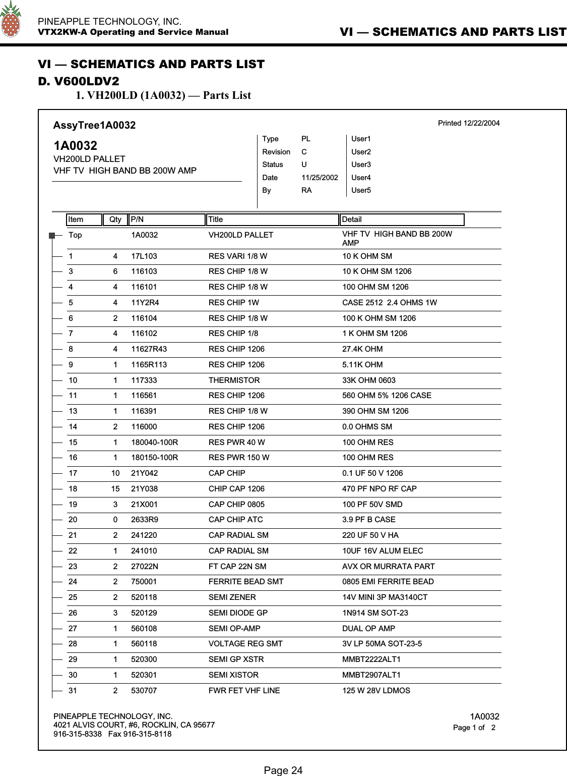
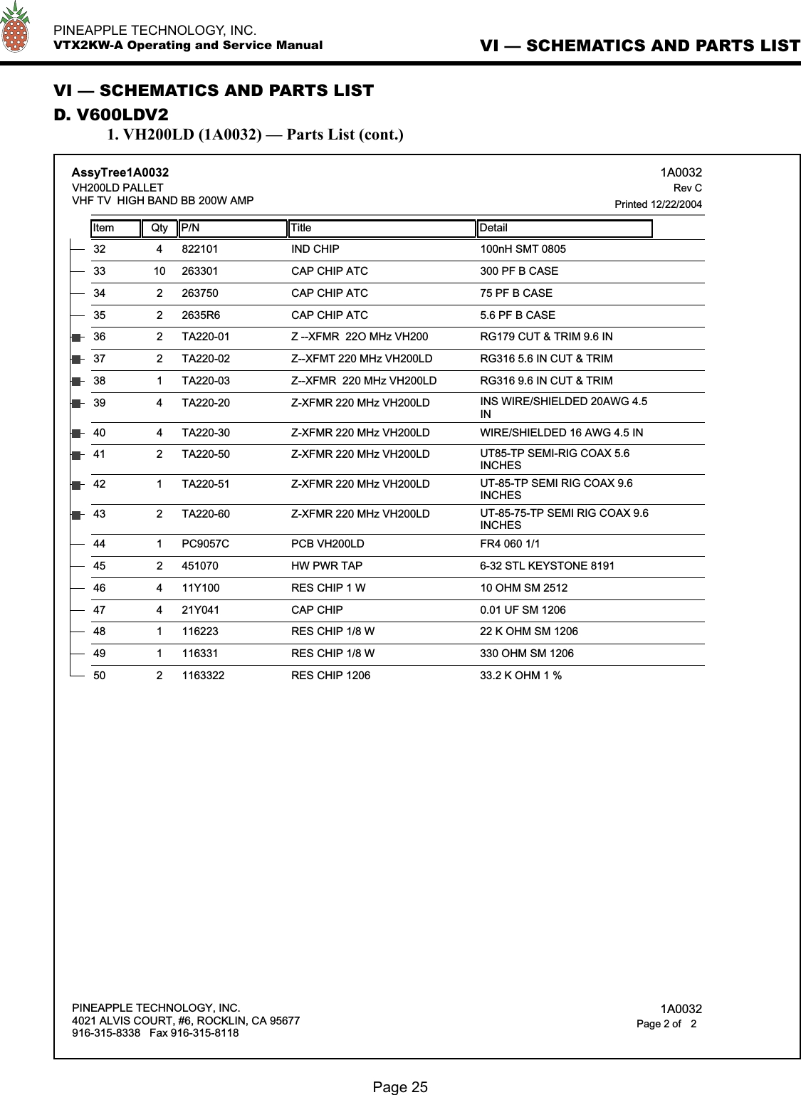
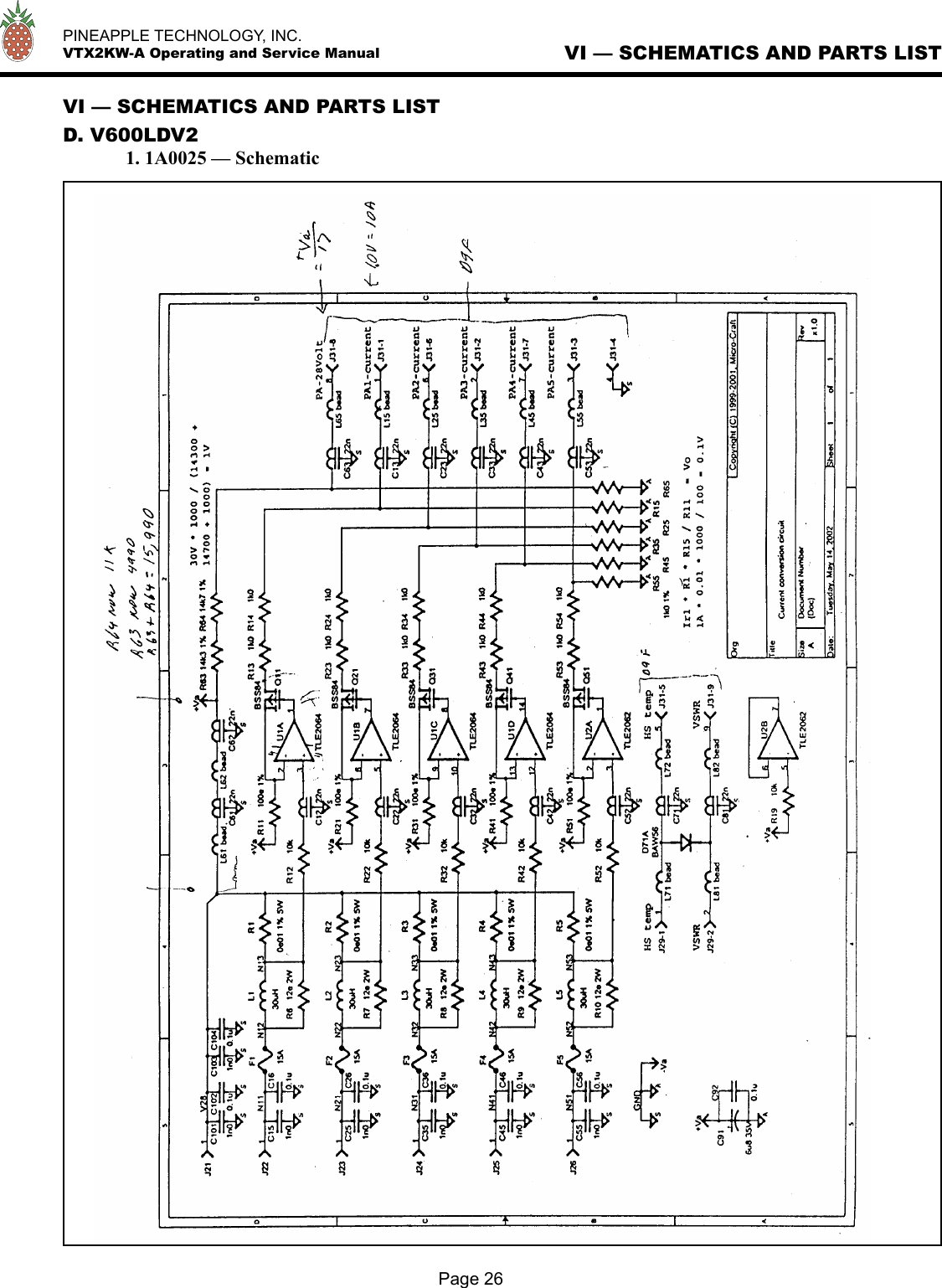
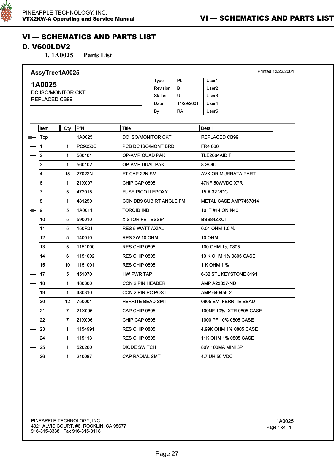
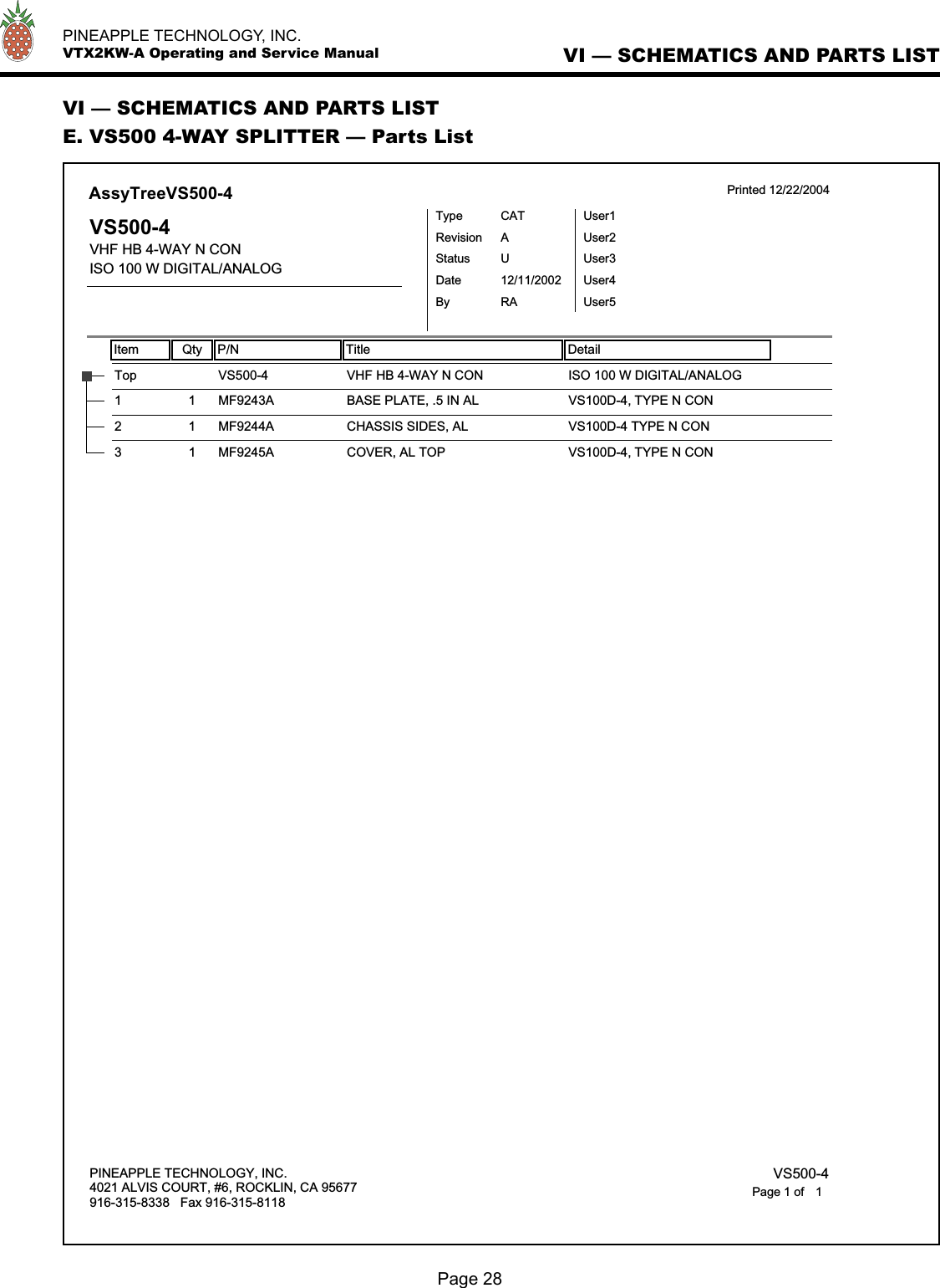
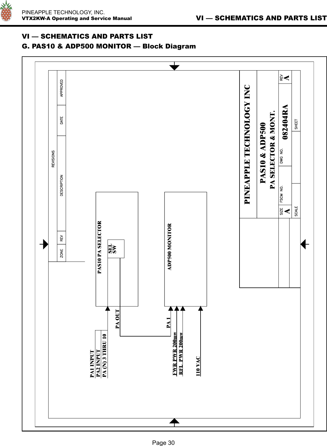
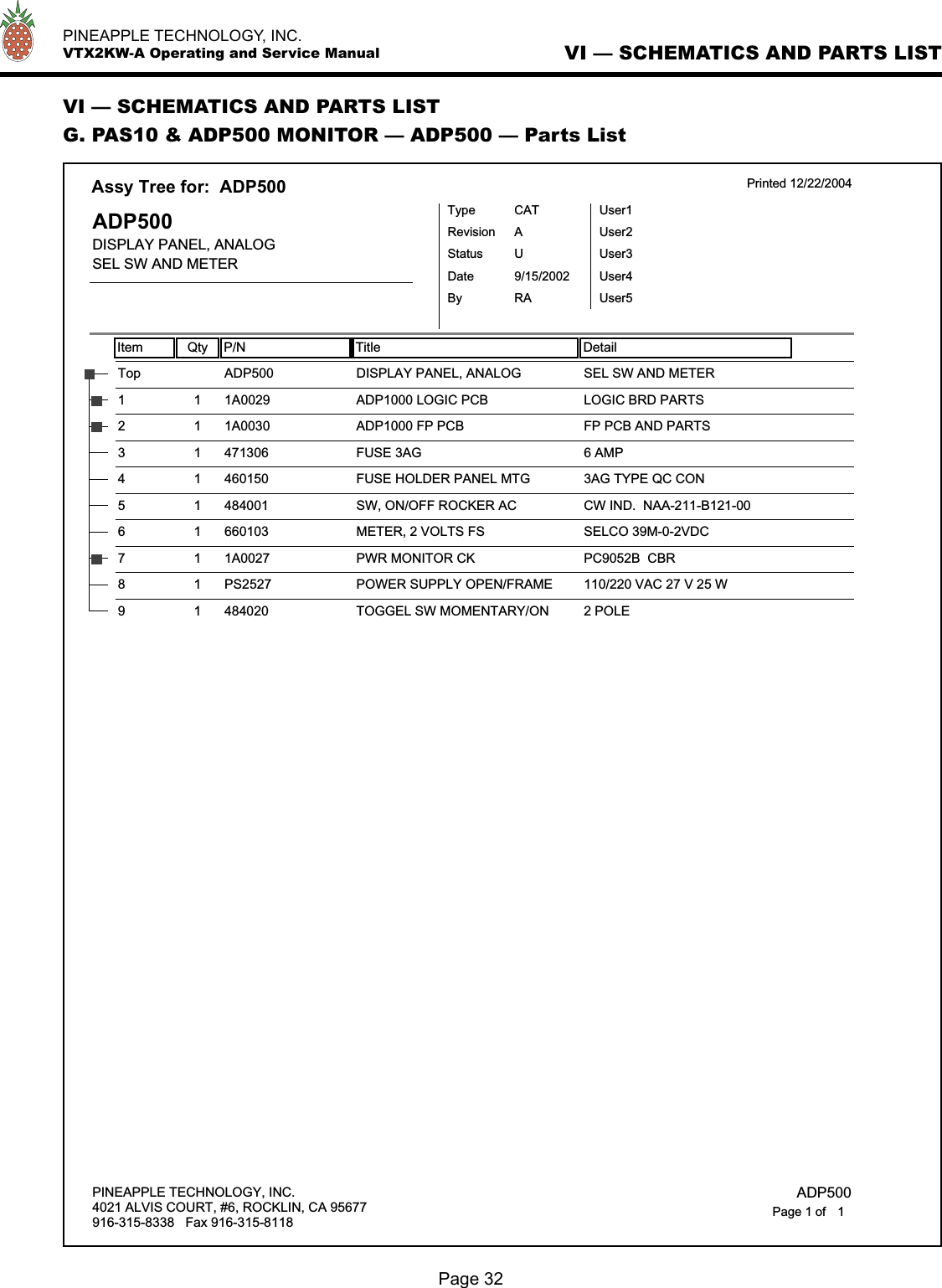
Pineapple Technology VTX2KW 2 KW VHF TV TRANSMITTER User Manual VTX2KW Op serv Manual indd
Pineapple Technology, Inc. 2 KW VHF TV TRANSMITTER VTX2KW Op serv Manual indd
UserManual.wiki
>
Pineapple Technology
>
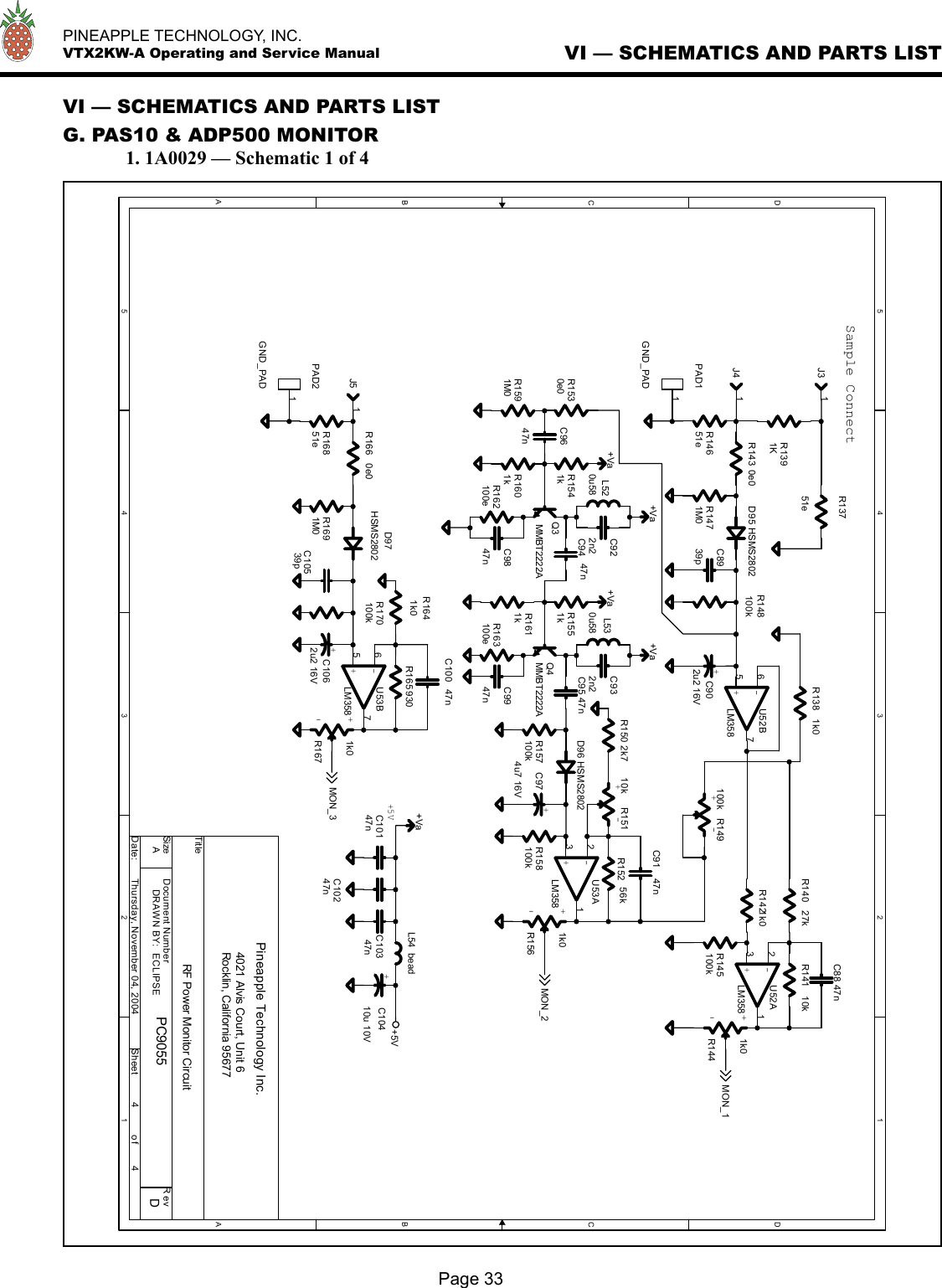
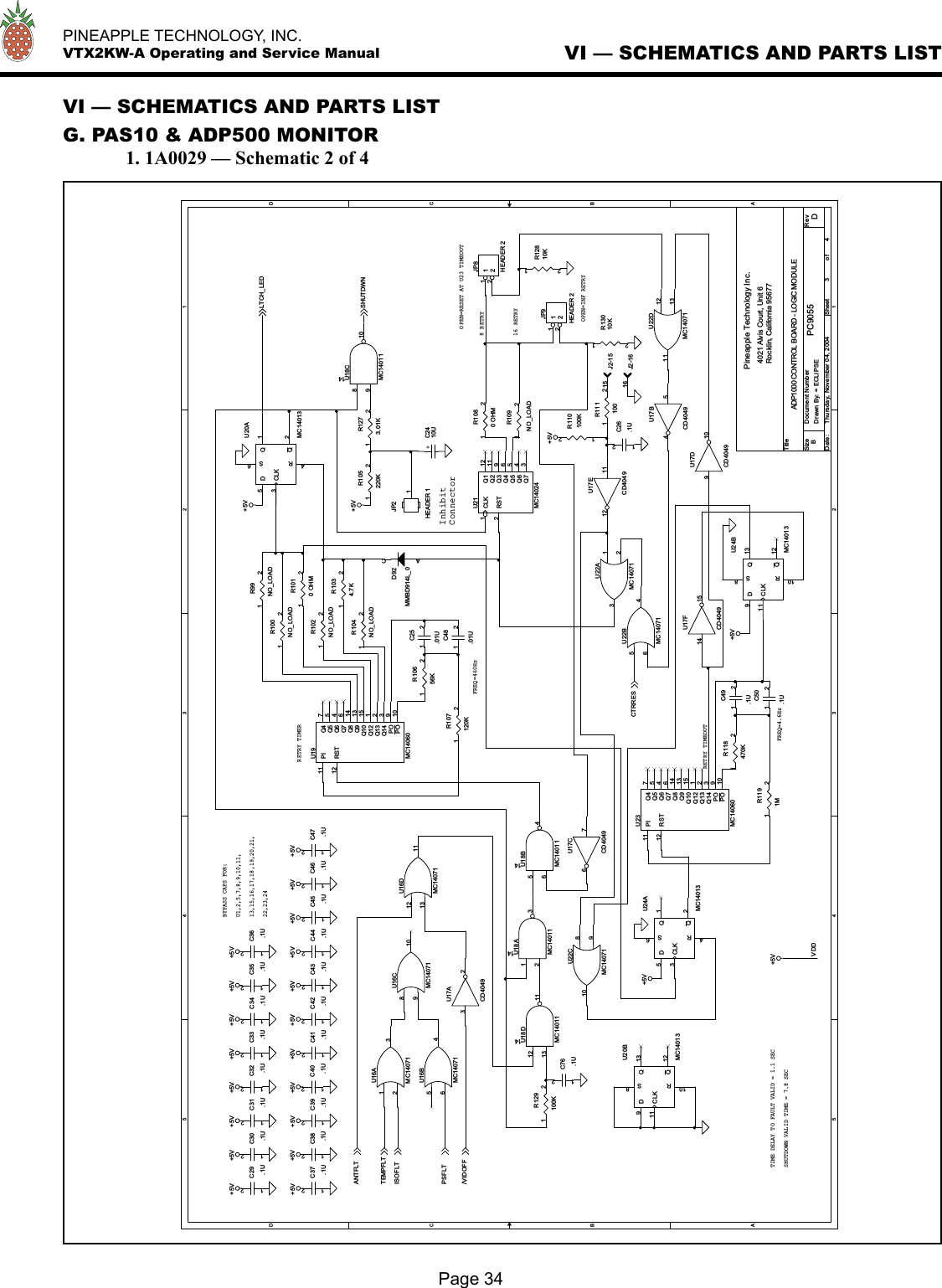
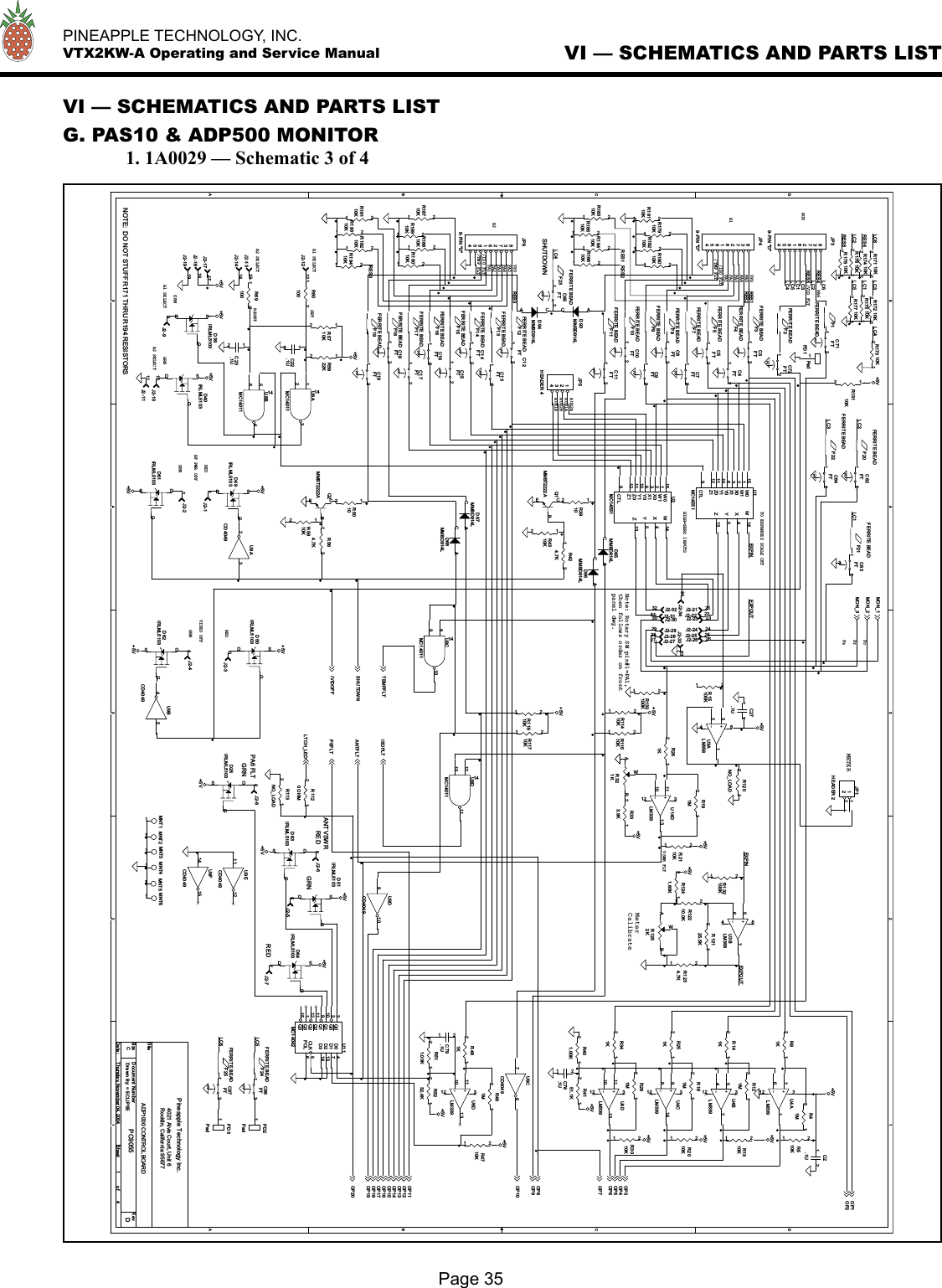
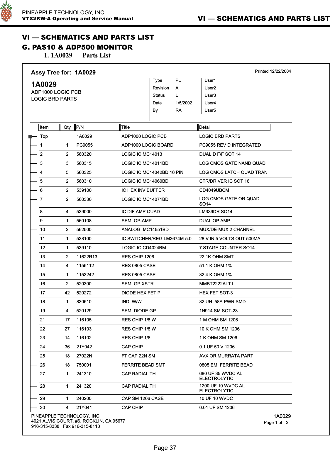
VTX2KW User Manual
User Manual
Navigation menu
Upload a User Manual
Namespaces
Wiki Guide
HTML
PDF
Info
Views
User Manual
Discussion / Help
Navigation