Pineapple Technology VTX2KW 2 KW VHF TV TRANSMITTER User Manual VTX2KW Op serv Manual indd
Pineapple Technology, Inc. 2 KW VHF TV TRANSMITTER VTX2KW Op serv Manual indd
User Manual

V T X 2 K W - A
INSTRUCTION MANUAL
SN:
PINEAPPLE TECHNOLOGY, INC.
DRAFT

PINEAPPLE TECHNOLOGY, INC.
VTX2KW-A Operating and Service Manual TABLE OF CONTENTS
Page 1
Section I — SAFETY NOTICES ........................................................................ 2
**READ THIS SECTION BEFORE INSTALLATION**
Section II — TRANSMITTER SPECIFICATIONS .............................................. 3
Section III — TRANSMITTER INSTALLATION ................................................. 5
Section IV — TRANSMITTER TURN-ON PROCEDURE .................................... 6
Section V — THEORY OF OPERATIONS
A. Introduction ............................................................................................................................7
B. ACDIS2 .. 7
C. AC2008 2KW Power Module ................................................................................................8
D. PAS10 and ADP500 Performance Monitor ............................................................................8
E. Remote Monitor and Control W/ABS ....................................................................................9
F. Modulator/Driver ..................................................................................................................10
G. VS500 4-Way Splitter ...........................................................................................................10
H. MFA1KW PA Mainframe Assembly ....................................................................................10
I. V600LDV2 Integrated Amplifier Assembly .........................................................................11
J. VC2KW-4 Power Combiner with Coupler ..........................................................................11
K. BPV2KW Band Pass FIlter ..................................................................................................11
Section VI — SCHEMATIC AND PARTS LISTS
A. VTX2KW-A .........................................................................................................................12
B. ACDIS2 14
C. MFA1KW .............................................................................................................................17
1. 1A0035 Status Board ........................................................................................................19
D. V600LDV2 ...........................................................................................................................21
1. VH200LD .........................................................................................................................23
2. 1A0025 Power Distribution and Monitor .........................................................................26
E. VS500 4-Way Splitter ...........................................................................................................28
F. VC2KW 4-Way Combiner ...................................................................................................29
G. PAS10 and ADP500 PA Monitor ..........................................................................................30
H. 1A5001/2 Isolator Assembly ................................................................................................40
Section VII — RECOMMENDED ROUTINE MAINTENANCE .......................... 42
Section VIII — ADJUSTMENTS AND TUNING .............................................. 43
Section IX — PROBLEM SOLVING / TROUBLE SHOOTING .......................... 45
Section X — WARRANTY .............................................................................. 47
Section XI — EXTENDED WARRANTY .......................................................... 48

PINEAPPLE TECHNOLOGY, INC.
VTX2KW-A Operating and Service Manual I — SAFETY NOTICES
I — SAFETY NOTICES
**READ THIS SECTION BEFORE INSTALLATION**
SEVERE ELECTRICAL SHOCK OR BURNS MAY OCCUR IF
THIS EQUIPMENT IS USED IMPROPERLY.
~~~~~~~~~~~~~~~~~~~~~~~~~~~~~~~~~~~~~~~~~~~~~~~~~
NEVER WORK ON THIS EQUIPMENT ALONE. ALWAYS HAVE ANOTHER PERSON PRESENT
WHILE WORKING ON ELECTRICAL CIRCUITS OR MOVING EQUIPMENT. COMMUNICATIONS
TO EMERGENCY SERVICES SHOULD BE AVAILABLE AT ALL TIMES.
~~~~~~~~~~~~~~~~~~~~~~~~~~~~~~~~~~~~~~~~~~~~~~~~~
BEFORE CONNECTING THIS EQUIPMENT TO ANY AC ELECTRICAL SOURCE READ THE SEC-
TION ON INSTALLATION. ALL ELECTRICAL WIRING FOR THIS EQUIPMENT MUST BE PER-
FORMED BY QUALIFIED ELECTRICIANS. ALL WIRING MUST BE COMPLIANT WITH LOCAL
ELECTRICAL CODES.
~~~~~~~~~~~~~~~~~~~~~~~~~~~~~~~~~~~~~~~~~~~~~~~~~
POWER AMPLIFIERS AND SUPPLIES ARE HEAVY. TO INSTALL THIS EQUIPMENT IN RACKS,
USE TWO (2) PERSONS TO AVOID POSSIBLE INJURIES.
~~~~~~~~~~~~~~~~~~~~~~~~~~~~~~~~~~~~~~~~~~~~~~~~~
NEVER OPEN THE CABINET ENCLOSURE OR UNPLUG CABLES OR WIRES WHILE THIS
EQUIPMENT IS OPERATING.
~~~~~~~~~~~~~~~~~~~~~~~~~~~~~~~~~~~~~~~~~~~~~~~~~
ALL SERVICE WORK MUST BE PERFORMED BY QUALIFIED TECHNICIANS ONLY.
IF ONE IS NOT AVAILABLE LOCALLY, CONTACT PINEAPPLE TECHNOLOGY, INC. FOR
A LIST IN YOUR AREA.
Page 2

PINEAPPLE TECHNOLOGY, INC.
VTX2KW-A Operating and Service Manual II — VTX2KW-A SPECIFICATIONS
II — VTX2KWA SPECIFICATIONS
OPERATING
Power Output ...................................................... 2 KW Peak Sync
Aural Power ......................................................... 200 Watts
RF Output Impedance .......................................... 50 ohms
Operating Frequency Range ................................ Channel 7 thru 13 NTSC
Frequency Stability .............................................. 1 PPM or better
Harmonic and Spurious ....................................... -60 dB or better ref to P-sync
Power Consumption ............................................8 KW Maximum
AC Line Voltage .................................................. 208-240 V AC SINGLE PHASE
VIDEO PERFORMANCE
Visual Frequency Response ................................. +/- 1 dB across the TV Channel -1.25 MHz to 4.75 MHz
relative to visual carrier.
Differential Gain .................................................. <7 %
Differential Phase ................................................ <10 Degrees
ICPM ................................................................... <5 Degrees
Low Frequency Linearity .................................... <15 %
2T K Factor .......................................................... 3 %
Group Delay ........................................................ Meets FCC Part 73 rule
Video Input Impedance ........................................ 75 ohms
Video Input Level ................................................ 1 volt p-p
Variation of output power .................................... <5 %
Regulation of output power ................................. <5 % Typical
Video Signal to Noise Ratio ................................ < 45 dB un-weighted
THESE SPECIFICATIONS ARE SUBJECT TO CHANGE WITHOUT NOTICE
Page 3

PINEAPPLE TECHNOLOGY, INC.
VTX2KW-A Operating and Service Manual II — VTX2KW-A SPECIFICATIONS
Page 4
AUDIO PERFORMANCE
Audio Response ................................................... Meets FCC Pre-emphasis Curves
Distortion ............................................................. <1 % THD
FM Noise ............................................................. 50 dB or better
AM Noise ............................................................ 40 dB or better
AM Synchronous Noise ...................................... 40 dB typical
Operating Temperature ........................................ -10 to +35 degrees Celsius Ambient
Altitude ................................................................ 5000 feet without additional cooling
Cooling requirements .......................................... Unobstructed Air flow of 2000 CFM
Minimum required at sea level with ambient
temperature of < 37 degrees Celsius
RF Output connectors .......................................... 7/8 EIA Flange
Weight .................................................................. 700 pounds est.
Dimensions .......................................................... 80” X 22” X 24” (H x W x L)
THESE SPECIFICATIONS ARE SUBJECT TO CHANGE WITHOUT NOTICE.

PINEAPPLE TECHNOLOGY, INC.
VTX2KW-A Operating and Service Manual
Page 5
III — TRANSMITTER INSTALLATION
To insure long and reliable trouble free service from the VTX2KWA transmitter the following steps for
installation are recommended.
1. MECHANICAL INSTALLATION: The VTX2KWA was designed to be installed in a building pro-
tected from the weather. The building should have a hard surface floor such as concrete with a mois-
ture barrier. This barrier could be pressure treated wood sub-flooring which could be anchored to the
concrete and to the transmitter to make the installation earth quake resistant.
Allow a minimum of three feet around the transmitter cabinet for service access. The top of the trans-
mitter should be clear for three feet to allow the air to exhaust from the transmitter.
Air flow thru the transmitter is approximately 2000 CFM. Provisions for air inlet and exhaust from the
room must allow air flow with minimal obstruction. In the event that the room temperature exceeds 35
degrees Celsius, cooling air must be provided so that the room temperature will not exceed 35 degrees
Celsius under worse case conditions.
Notice: This equipment is HEAVY and must be handled by professional movers with proper equipment.
Any damage caused by the installers is not covered under warranty. Check to insure that installing crews
have proper insurance coverage.
2. GROUNDING: Transmitter grounding is VERY IMPORTANT and must be done correctly for safety
and operational reasons. A typical installation may be done as follows:
Use a heavy gauge wire such as #2 AWG strained copper or solid copper buss 1 inch wide by 1/8 inch
thick for connections. The bonding between the transmitter and the ground rods must be good quality
and protected from corrosion. The ground wires should run over the floor and connected to the ground
rods located outside the building. The wire should not go thru the concrete floor but over and around it.
3. AC WIRING: A ten foot cable has been provided with the transmitter to facilitate the connection to the
AC Main power source. Connections to the AC Main should be made as follows:
RED and BLACK are connected to the 208-240 VAC SINGLE PHASE terminals
WHITE WIRE is connected to the NEUTRAL terminal
GREEN WIRE is connected to the SAFETY GROUND
NOTICE: All wiring of this type must be done by A QUALIFIED ELECTRICIAN and must conform
to LOCAL and NATIONAL Wiring CODES.
Consult with your electrician to insure that the proper breaker size is selected for the main circuit.
4. ANTENNA CONNECTION: The transmitter is equipped with a 7/8 EIA Flange connector located at
the top of the rack. Connecting the transmitter to the antenna must be performed by qualified person-
nel. Conditions vary from site to site so some engineering may be required to insure that the antenna is
receiving the correct amount of power to comply with FCC licenses and to insure safety from lighting
etc.
III — TRANSMITTER INSTALLATION

PINEAPPLE TECHNOLOGY, INC.
VTX2KW-A Operating and Service Manual IV — TRANSMITTER TURN-ON PROCEDURE
Page 6
IV — TRANSMITTER TURN-ON PROCEDURE
Before applying AC Power to the transmitter for initial turn on and check out, the installation should be
approved by a qualified broadcast engineer. The Turn on procedure that follows is recommended by Pine-
apple Technology, Inc. engineering staff:
1. Check transmitter load or antenna for proper installation and connection to the transmitter.
2. Open the transmitter and inspect all cables and wires for lose connections or broken wires in the
rack assembly
3. Check for damage to the equipment mounted in the rack.
4. Check all AC breakers and on/off switches to ensure that all are OFF.
5. TURN ON THE MAIN AC BREAKER LOCATED IN THE SUB-PANEL WHERE THE AC POWER
CORD WAS CONNECTED.
6. TURN ON THE MAIN AC BREAKER LOCATED ON THE ACDIS2 POWER DISTRIBUTION
PANEL LOCATED ON THE FRONT OF THE TRANSMITTER. A GREEN LIGHT SHOULD
COME ONE INDICATING POWER IS ON.
7. TURN ON THE AC SWITCH LOCATED ON THE FRONT OF THE ADP500. THE INDICATING
LIGHTS SHOULD BE ON AND READY FOR OPERATION
8. TURN ON THE AUX BREAKER LOCATED ON THE ACDIS2 FRONT PANEL. THE PA FANS
AND THE RACK EXHAUST FANS SHOULD COME ON.
9. TURN ON THE POWER SUPPLY BREAKERS LOCATED ON THE FRONT OF THE ACDIS2.
CHECK THE AC 2008 POWER MODULES (6) EACH TO SEE IF THE GREEN LIGHTS ARE
INDICATING NORMAL OPERATION.
10. USING THE ADP500 & PAS10 CHECK THE IDLING CURRENTS ON EACH PA TO ENSURE
THAT THE CURRENTS ARE IN THE CORRECT RANGE. TYPICAL RANGE IS 1.5 TO 2.5
AMPS. SEE ADP500 OPERATING SECTION FOR DETAILS
NOTICE: The Modulator/driver has been set at the factory so that the output power indication on the
ADP500 will show 100% or 2 KW p-sync power level. It is important to read the instruction manual sup-
plied with the modulator to locate key adjustment devices on the front panel. The output level adjustment
will be necessary for the next step in the turn on procedure.
11. Locate the level adjustment on the modulator/drive and turn the level down to minimum or CCW.
12. Turn on the power switch located on the modulator/up-converter rear panel.
13. Apply a video signal (1 volt P-P) to the video input terminal
14. Slowly increase the output level adjustment while watching the RF Output level on the
ADP500 until it reads to 50%.

PINEAPPLE TECHNOLOGY, INC.
VTX2KW-A Operating and Service Manual
15. Using the ADP500 reflected power indication check the LOAD reflected power. This should be less
that 5% reflected.
16. Return to the PA current readings on the ADP500 to verify that all the currents are approximately
the same.
17. With successful performance to step 17, the transmitter output power can be increased using the
output level adjustment on the modulator to achieve 100%. The aural power can be added at this time
not exceeding 10% of output p-sync power as indicated on the ADP500.
V — THEORY OF OPERATIONS
A. INTRODUCTION
The VTX2KWA transmitter was designed to meet or exceed all FCC applicable specifications for TV
Broadcast Equipment. Special attention was given to the selection of sub-assemblies and components to
achieve maximum reliability and minimum down time. The construction of the VTX2KWA is BASIC
and MODULAR with most components field replaceable. Special emphasis was placed on KEEPING IT
SIMPLE and returning to more traditional transmitter layouts and instrumentation.
This transmitter was designed for Analog (NTSC) transmission with provisions and options available to
convert to Digital Service when necessary.
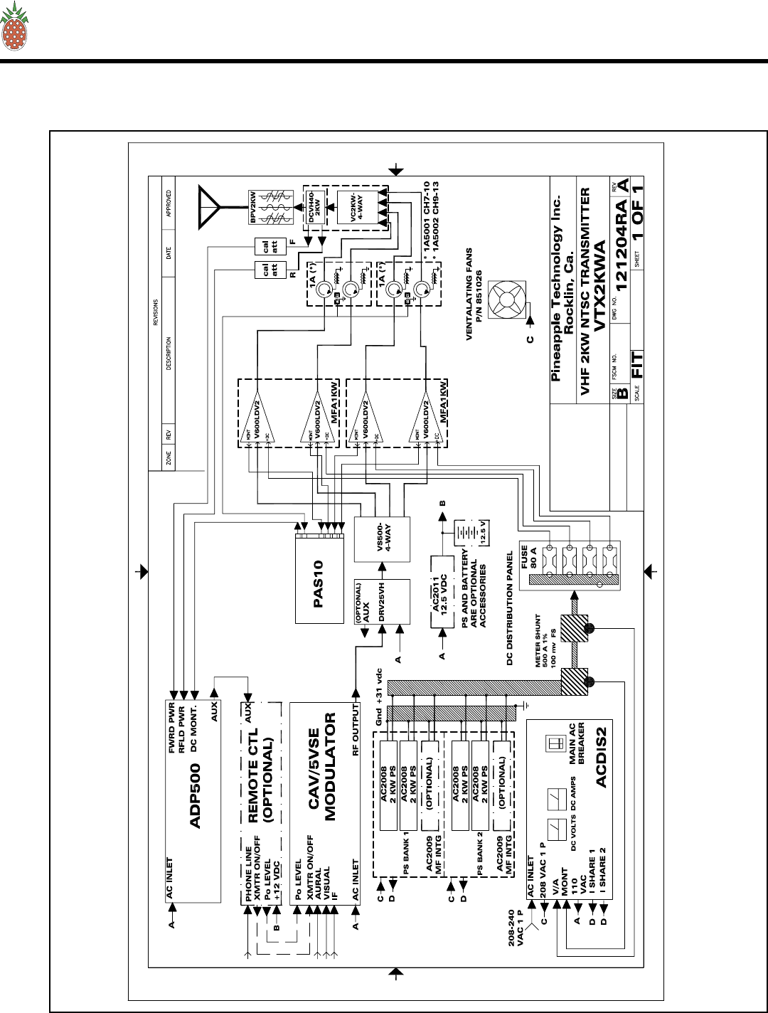
Refer to the VTX2KWA block diagram (page 12) for an overview of the transmitter architecture. The key
subassemblies are listed below followed by a brief description. This will give the technician basic infor-
mation needed to understand the operations of the transmitter and the function of each subassembly.
SEE SECTION VI.A FOR PARTS LIST (page 13)
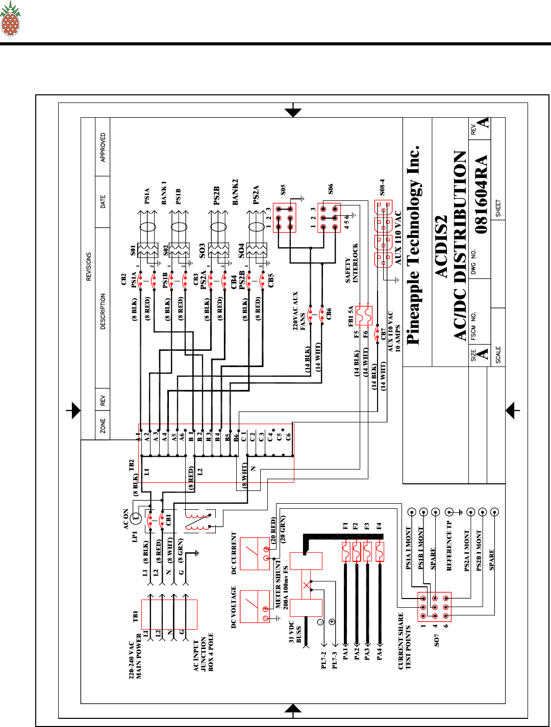
B. ACDIS2 AC & DC DISTRIBUTION
The ACDIS2 is the primary AC power inlet module. The VTX2KWA transmitter was designed to except
208 to 240 V AC SINGLE PHASE using a FOUR (4) wire connection. The four wires are
2 wires for 208-240V AC single phase
1 wire for neutral connection
1 wire for safety ground connection
CAUTION: Connection to the AC Primary Source must be made using all four wires listed above.
Follow the wiring instruction given in the AC WIRING section III. 3 (page 5). If not followed, severe
damage to the transmitter and or electrical shock is possible.
The ACDIS2 performs the following functions:
1. Provides a primary AC power breaker point to shutdown the transmitter.
2. Provides 208 VAC single phase power to each of the 2 KW DC power supplies with individual breaker
points for added safety.
3. Provides 110 VAC circuits for Modulator, ADP500, Auxiliary Power Source, and AUX Power where
needed.
V — THEORY OF OPERATIONS
Page 7

PINEAPPLE TECHNOLOGY, INC.
VTX2KW-A Operating and Service Manual
4. Analog metering is provided to monitor the Power supply voltage and current being applied to the RF
Amplifier stages
5. Power supply current sharing test points are provided for checking current sharing between power
supply modules.
SEE SECTION VI.B FOR SCHEMATIC AND PARTS LIST (page 14)
C. AC2008 2 KW POWER MODULE
The VTX2KWA transmitter is designed with over 8 KW of DC power available to the transmitter. To
achieve this level, the power supply is made up of four RR6000 (PTI P/N AC2008) power module
mounted into TWO mainframe assemblies RU2 (PTI P/N AC2009) which are capable of managing three
2 KW modules each.
The power modules are “HOT PLUGGABLE” and can be removed or installed without turning off the
transmitter.
Each power supply modules has OVER VOLTAGE, OVER CURRENT, AND OVER TEMPERATURE
protection as well as a fault signal in the event of a failure.
REFER TO MANUFACTURER’S MANUAL PROVIDED WITH THE VTX2KWA.
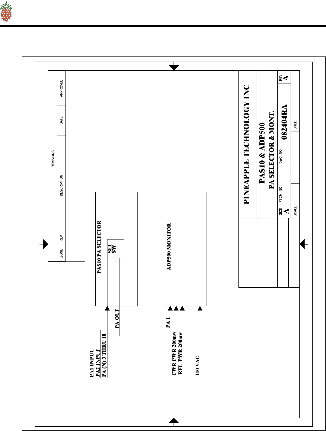
D. PAS10 & ADP500 PERFORMANCE MONITOR
The PAS10 & ADP500 PERFORMANCE MONITOR provides the following functions:
1. Monitors FORWARD AND REFLECTED POWER to the antenna and presents it as a percentage of
power rating. The transmitter comes set to 100% P-Sync power based on the ratings of the transmitter.
2. Monitors Aural Power as a percentage of P-Sync rating (10 % typical)
3. Provides a HIGH ANTENNA VSWR MONITOR In the event of an antenna or coax failure where the
reflected power exceeds 25% the transmitter will shutdown. Front panel LED with change from green
to red in case of a fault.
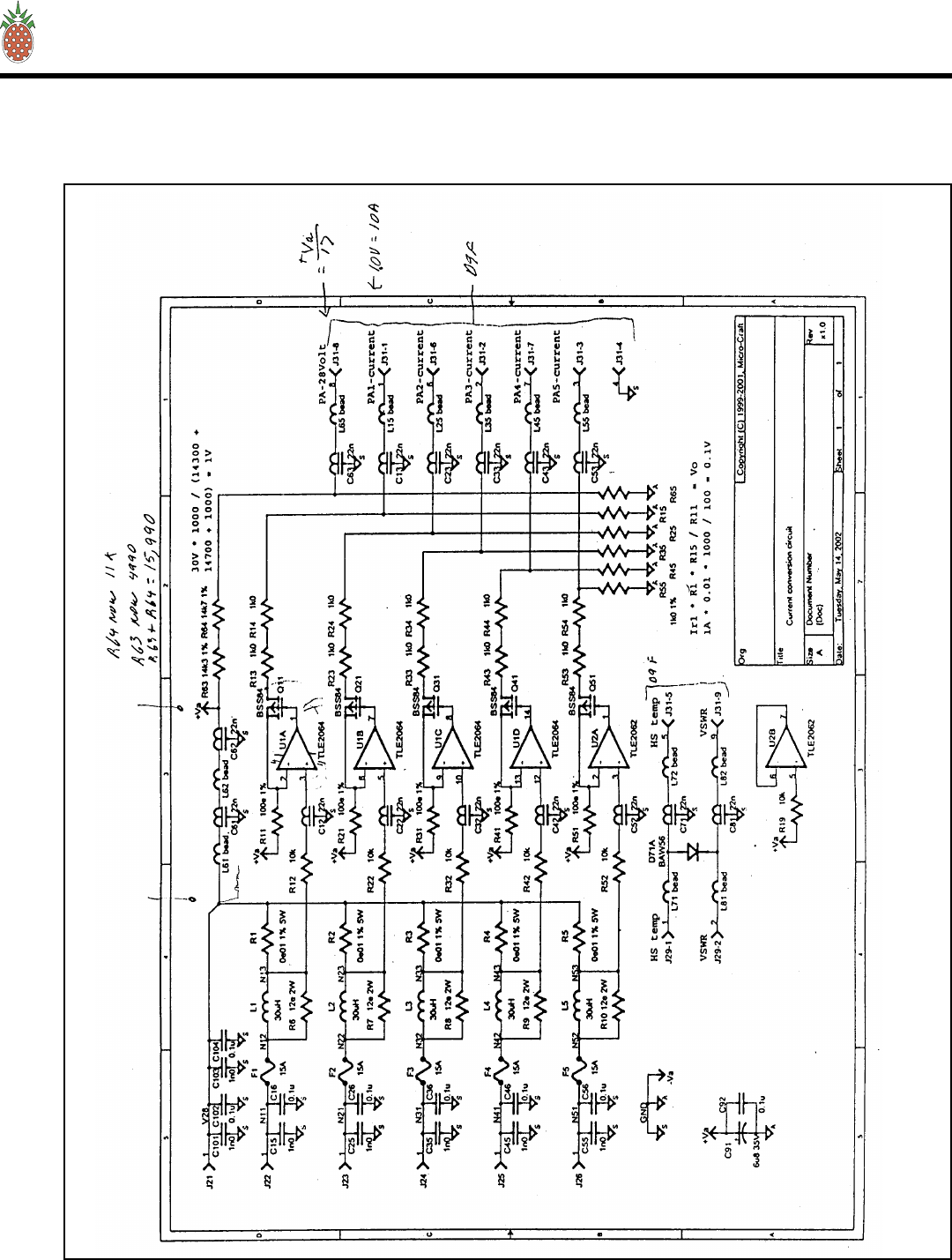
4. Provides current monitoring of all the pallets used in the six V600LDV2 power amplifier assemblies.
The current levels can be read directly from the multi-meter on the front panel. Individual pallets are
selectable on the ADP500 and the PA assemblies are selected using the PAS10. In normal operations, a
PA FAULT is indicated by going from green to red. RED indicates that the current level is below 500
ma and a transistor could have failed. To read the actual current, select the appropriate PA Bank using
the PAS10. The ADP500 will now display status of each pallet in that PA. The multi-meter will read
the actual current.
5. A PA INHIBIT switch is provided for failure diagnostic purposes. When activated, this switch allows
the technician to monitor the bias currents for each pallet. These readings should be recorded when the
transmitter is first installed and used as a reference. This is the best way to trouble shoot possible tran-
sistor problems. When in the PA INHIBIT mode, the RF PWR OFF LED will change from green to red
indicating that the “SHUTDOWN LINE” Is at a TTL 0 state and the output power has been reduced to
near zero.
6. An RF MONITOR port (BNC) is available to connect a spectrum analyzer or other test equipment for
monitoring the output signal.
V — THEORY OF OPERATION
Page 8

PINEAPPLE TECHNOLOGY, INC.
VTX2KW-A Operating and Service Manual V — THEORY OF OPERATION
Page 9
THE METER SELECTOR SWITCHES
The PAS10 is used to select the appropriate PA Module (V600LDV2) for performance display on the ADP500. PA
designations are PA1 starting from the top row going left to right with PA4 being on the right side in the second
row down when viewed from the front of the transmitter.
The Rotor Switch on the ADP500 is the detail selector for the multi-meter. The various positions are defined as
follows:
PA1 THRU PA5 ................................................... Reads PA pallet currents as selected
Typical reading in INHIBIT MODE 1.5 TO 2.2 A
Typical reading 5-7 A for PA1-PA4 with normal picture or 50% APL test waveform
Typical reading 2-3 A for PA5 with normal picture or 50% APL test waveform
PA6 ..................................................................... NO CONNECTION
PS VOLTS ........................................................... Reads DC Voltage applied to PA Stages
Typical reading would be +29 to 32 VDC
P FWRD ............................................................... Reads PA output power in P-Sync percentage of rating.
Full power reading would be 100%
P RFLD ................................................................ Reads PA output power being returned from the load and
displayed as a percentage of forward power.
Typical reading would be < 5% indicated.
P AURAL ............................................................. Reads the AURAL POWER component as a percentage of
forward power. Typical reading would be 10%
AUX 1 & AUX 2 ................................................. not used in this configuration
REFER TO SECTION VI.H. FOR SCHEMATICS AND PARTS LIST (page 33)
E. REMOTE MONITOR AND CONTROL WITH ABS
This equipment is OPTIONAL and may be required to ensure remote control operational capability.
The Remote Monitor is used to monitor the operational status of the transmitter and will allow the operator to turn
RF on or off and adjust power levels. The following items are monitored or controlled:
1. Transmitter on/off function
2. Power output level monitor and adjustment.
3. AC Line voltage status. With ABS you can be notified if there is a power failure at the side.
4. Various other custom options are available. Specify these at the time the transmitter is purchased and they will
be included if possible.
Remote monitoring requires a Phone line connection. Information can be accessed via a PC Terminal or via a
‘VOICE COMMAND LINE’. Either option is standard with this system.
The Auxiliary power unit requires a battery connection. A common car battery (12 VDC) can be used with a char-
ger as an ABS. This will run the Monitor and provide access to transmitter status for several hours.

PINEAPPLE TECHNOLOGY, INC.
VTX2KW-A Operating and Service Manual
A manual for this equipment is provided by the Manufacture and is included in the VTX2KWA package
shipped with the transmitter. This manual is only included if this option was purchased for delivery with
the transmitter.
REFER TO INSTRUCTION MANUAL PROVIDED WITH THIS PACKAGE
F. MODULATOR
The heart of any TV Transmitter is the “MODULATOR”. This equipment receives the video and audio
signals as well as any control signals needed. The base band signals are converted to RF with an output
on the desired operating channel.
Detail operation of the Modulator with schematics and P/L is provided by the equipment manufacture.
REFER TO INSTRUCTION MANUAL PROVIDED WITH THIS PACKAGE
G. VS500 4-WAY SPLITTER
The VS500 4-WAY splitter receives the output of the Modulator/Driver and splits it into 4 parts with
phase and power levels equal. This unit is an isolated in-phase splitter and will provide some isolation in
the event one PA fails.
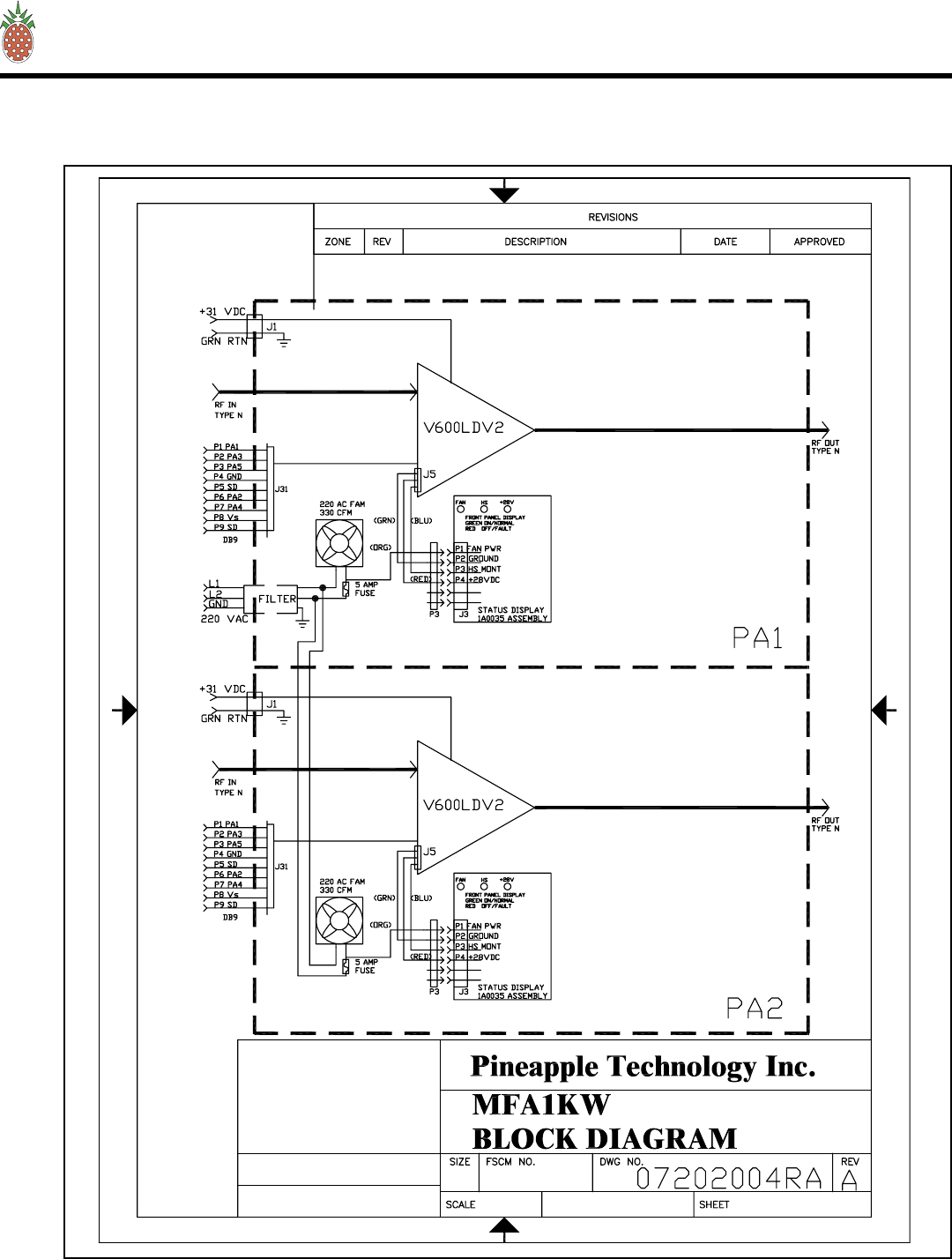
H. MFA1KW PA MAINFRAME ASSEMBLY
The MFA1KW is the main RF Power Amplifier housing which accommodates two (2) V600LDV2
Amplifiers. The housing includes the following:
2 ea ....................................................................... 330 CFM cooling fans
2 each ................................................................... Air filter assemblies
2 each ................................................................... Front panel status PC Boards
1 each ................................................................... Main chassis
2 each ................................................................... Mechanical slide assemblies
1 each ................................................................... AC Filtered inlet for cooling fans
SEE SECTION VI.C. FOR SCHEMATICS AND PARTS LIST (page 19)
V — THEORY OF OPERATION
Page 10

PINEAPPLE TECHNOLOGY, INC.
VTX2KW-A Operating and Service Manual
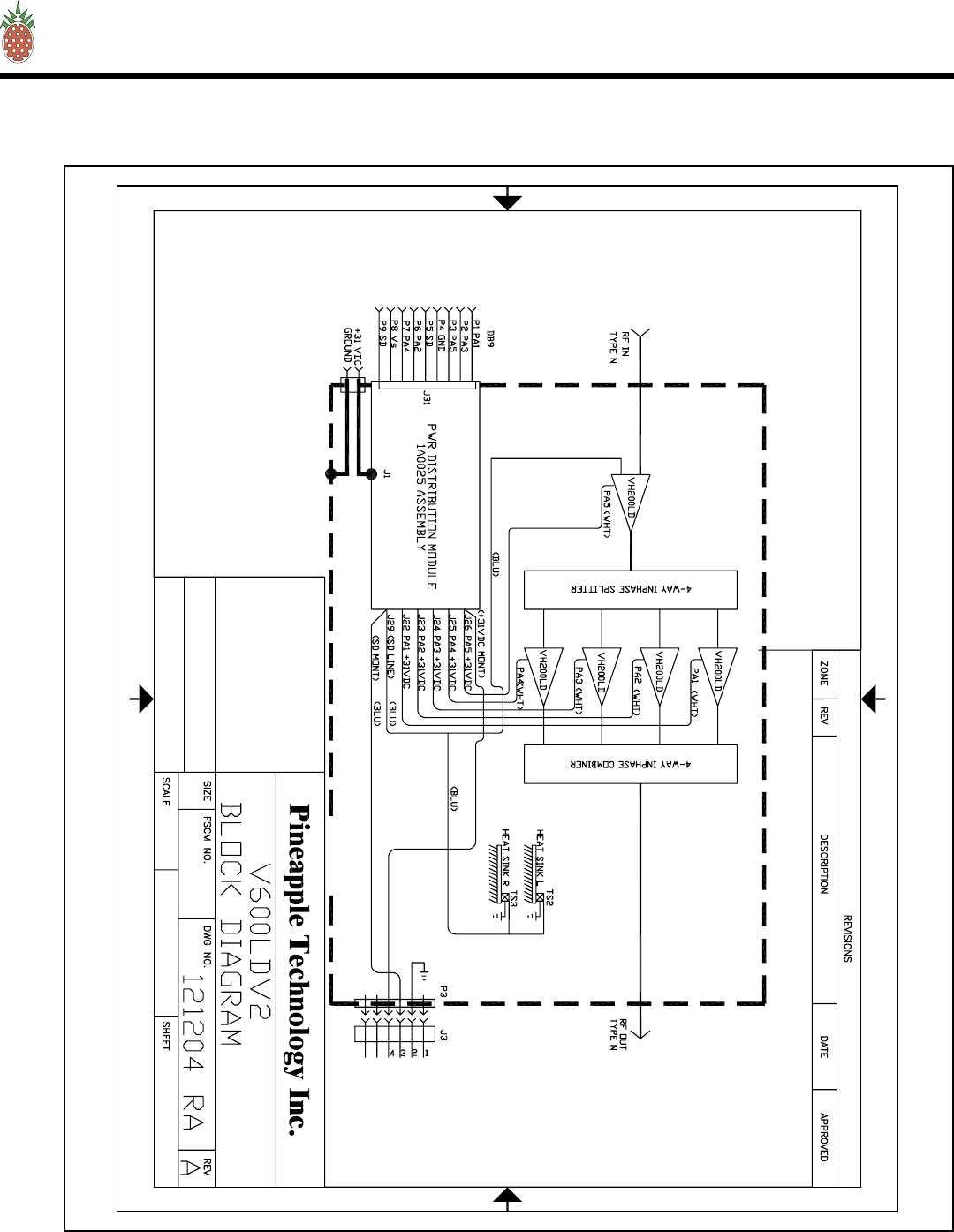
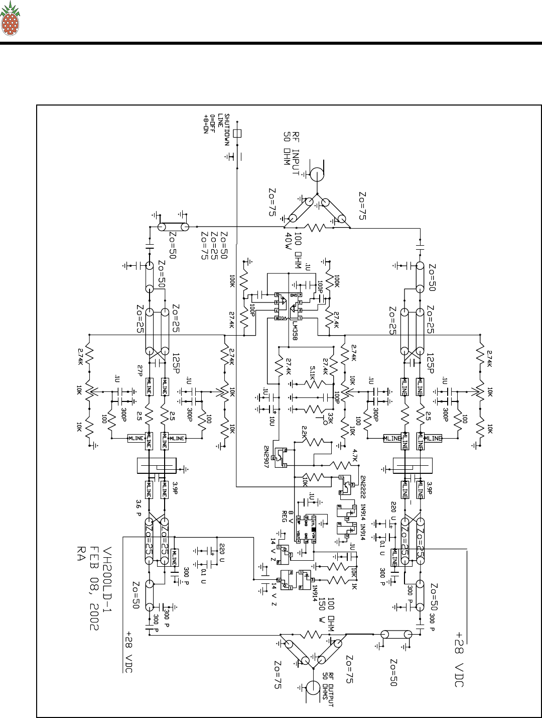
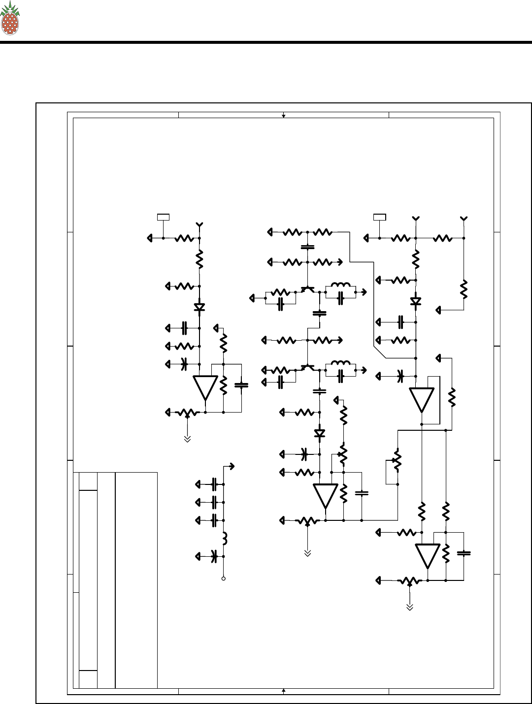
I. V600LDV2 POWER AMPLIFIER
The V600LDV2 is the main RF Power Amplifier Assembly used in the VTX2KWA. Each Ampli-
fier assembly is made up of five (5) VH200LD power pallets. Each power pallet uses two (2) Phillips
BLF647 power LDMOS FETs. These amplifiers are operated in Class A/AB or sometimes referred to as
“HARD AB”. This refers to the bias levels to achieve best linearity.
Each V600LDV2 amplifier assembly includes the following:
5 each ................................................................... VH200LD power pallets
1 each ................................................................... 4-way splitter
1 each ................................................................... 4-way combiner
1 each ................................................................... Pwr distribution module (1A0025)
2 each ................................................................... thermal sensors
1 each ................................................................... remote monitor port (DB9)
1 each ................................................................... front panel status port (Molex)
1 each ................................................................... filtered DC input port
1 each ................................................................... Type N panel mounted RF Input port
1 each ................................................................... Type N Panel mounted RF Output port
SEE SECTION VI.D. FOR SCHEMATICS AND PARTS LIST (page 21)
J. VC2KW-4 POWER COMBINER WITH COUPLER
The VC2KW-4 is a 4-way in-phase combiner with built in 40 dB dual directional coupler.
This assembly has no user servicable parts.
K. BPV2KW VHF BAND PASS FILTER
This Band Pass filter was designed to meet FCC Certification requirements with minimum loss of RF
Power. The BPV2KW comes tuned and tested to the operating frequency of the transmitter and should not
be adjusted without proper equipment. Replacement filters are available as P/N BPV2KW VHF
(+CHANNEL NUMBER).
This assembly has no user servicable parts.
V — THEORY OF OPERATION
Page 11
PINEAPPLE TECHNOLOGY, INC.
VTX2KW-A Operating and Service Manual
Page 12
VI — SCHEMATICS AND PARTS LIST
VI — SCHEMATICS AND PARTS LIST
A. VTX2KW-A

PINEAPPLE TECHNOLOGY, INC.
VTX2KW-A Operating and Service Manual VI — SCHEMATICS AND PARTS LIST
Page 13
VI — SCHEMATICS AND PARTS LIST
A. VTX2KW-A — Parts List
Item Qty P/N Title Detail
AssyTreeVTX2KWA Printed 12/22/2004
V
TX2KWA
VHF HB TV TRANSMITTER 2 KW
ANALOG TRANSMITTER
Type
Status
Revision
CAT
U
A
User1
User2
User3
User4
User5
Date
By
12/12/2004
RA
VHF HB TV TRANSMITTER 2 KW Top VTX2KWA ANALOG TRANSMITTER
AC & DC DISTRIBUTION1 1 ACDIS2 UTX2KWA TRANSMITTERS
MODULATOR2 1 CAV/5VSE 5 WATT VHF
VHF HB 600W LDMOS PA3 4 VH600LD 5 EA VH200LD MODULES
1 KW MAIN FRAME4 2 MFA1KW UHF/VHF ASSEMBLIES
DISPLAY PANEL, ANALOG5 1 ADP500 SEL SW AND METER
PA SEL SW FOR ADP5006 1 PAS10 10 POLE INPUT 1 OUTPUT
VHF HB 4-WAY N CON7 1 VS500-4 ISO 100 W DIGITAL/ANALOG
VHF HB 2 KW COMBINER8 1 VC2KWH-4 4-WAY WITH DC BUILTIN
2 KW 31 VDC PWR SUPPLY10 4 AC2008 UNI-PWR TRS6000-406
6KW 3EA PWR SUPPLY MAIN
FRAME
11 2 AC2009 UNIPOWER RRS2U
ISOPLATE VHF HB1 175-200 MHz12 2 1A5001 INC ISOLATORS, TERM, MECH
MTG
ISOPLATE VHF HB2 190-220 MHz13 2 1A5002 INC ISOLATOR, TERM, MECH
PLATE
FAN AC 208 2000 CFM EXHAUSE16 1 851026 MULTIFAN VOSTERMANS
4VF1042A
40 RU ASSEMBLIED RACK17 1 MFC40RU BLACK CONTEMPRA 2 WELDED
CABLE GRIP O.67-0.87 OD18 1 AC4352 MTG HOLE 1,325 WIRE SIZE 8/4
PINEAPPLE TECHNOLOGY, INC.
4021 ALVIS COURT, #6, ROCKLIN, CA 95677
916-315-8338 Fax 916-315-8118
VTX2KWA
1Page 1 o
f
PINEAPPLE TECHNOLOGY, INC.
VTX2KW-A Operating and Service Manual
Page 14
VI — SCHEMATICS AND PARTS LIST
VI — SCHEMATICS AND PARTS LIST
B. ACDIS2

PINEAPPLE TECHNOLOGY, INC.
VTX2KW-A Operating and Service Manual VI — SCHEMATICS AND PARTS LIST
Page 15
VI — SCHEMATICS AND PARTS LIST
B. ACDIS2 — Parts List
Item Qty P/N Title Detail
AssyTreeACDIS2 Printed 12/22/2004
ACDIS2
AC & DC DISTRIBUTION
UTX2KWA TRANSMITTERS
Type
Status
Revision
PL
U
A
User1
User2
User3
User4
User5
Date
By
6/28/2004
RA
AC & DC DISTRIBUTIONTop ACDIS2 UTX2KWA TRANSMITTERS
DC PANEL METER 50 V FS1 1 660110 HOYT MODEL 3115 1-1/2 ANA
PANEL
DC AMP METER 300 A FS2 1 660113 HOYT 3115 100mv FS
SHUNT, METER 100 mv FS3 1 670300 Lightweight shunt, 100 Millivolt,
300 amp.
AC CKT BREAKER4 1 AC3110 115 VAC 10 AMPS RS TYPE
AC POWER DISTRIBUTION BLOCK5 1 AC8000 3 POLE 840 A 60O VAC
AC PANEL MTG OUTLET6 1 AC5105 4 POSITION "GANGED" 15A
115VAC
AC POWER PLUG 220AC 16A8 4 AC4111 POWER INLET SCHURTER
4300.0922
MOLEX CRIMP TERM PLUG9 2 480461 PLUG HOUSING 6 POLE
MOLEX CAP STRAIN RELIEF10 4 480462 ACDIS SUBASSEMBLIES
MOLEX CRIMP TERM 6 POLE11 2 480460 CAP HOUSING PANEL MTG
MOLEX PIN CONTACTS LRG12 12 480463 CONN PIN 14-20 AWG TIN
CRIMP
MOLEX SOCKET CONTACTS13 12 480464 CONN SOCKET 14-20 AWG TIN
CRIMP
MOLEX PLUG HOUSING14 1 480465 9 POLE MATE-LOC
MOLEX CAP HOUSING15 1 480466 9 POLE
MOLEX STRAIN RELIEFS16 2 480467 9 POLE
FUSE FAST ACTING 80 AMP17 4 471380 USE WITH LFFB0001 HOLDER
FUSE HOLDER 400A18 4 460190 LITTELFUSE LFFB001
AC CKT BKR ELUMINATED19 5 AC3315 U600LPA 220 15 A 2 POLE
ACDIS MAIN CHASSIS20 1 MF9312 AL 090 MATERIAL ALODYNE/W
SILK
ACDIS MAIN COVER21 1 MF9313 1 & 2 KW 090 AL ALODYNE
ACDIS CHASSIS DIVIDER22 1 MF9315A 063 AL ALODYNE
PLATE, FRONT ACDIS223 1 MF9311
AC CKT BRKR24 1 AC3250 50 AMP 2-POLE 220V
HW, TIP JACK25 2 453000 RED, Insulated standard TIP JACK
HW TIP JACK26 2 453001 WHITE, Insulated standard TIP
JACK
HW, TIP JACK27 1 453002 BLACK, Insulated standard TIP
JACK
PINEAPPLE TECHNOLOGY, INC.
4021 ALVIS COURT, #6, ROCKLIN, CA 95677
916-315-8338 Fax 916-315-8118
ACDIS2
2Page 1 o
f

PINEAPPLE TECHNOLOGY, INC.
VTX2KW-A Operating and Service Manual
Page 16
VI — SCHEMATICS AND PARTS LIST
VI — SCHEMATICS AND PARTS LIST
B. ACDIS2 — Parts List (Cont.)
HW, TIP JACK28 2 453003 BLUE, Insulated Standard TIP
JACK
AC CORD GRIP29 1 AC4302 0.98 OD CABLE 1.3 HOLE MTG
AssyTreeACDIS2
Item Qty P/N Title Detail
ACDIS2
Printed 12/22/2004
Rev A
AC & DC DISTRIBUTION
UTX2KWA TRANSMITTERS
PINEAPPLE TECHNOLOGY, INC.
4021 ALVIS COURT, #6, ROCKLIN, CA 95677
916-315-8338 Fax 916-315-8118
ACDIS2
2Page 2 o
f
PINEAPPLE TECHNOLOGY, INC.
VTX2KW-A Operating and Service Manual VI — SCHEMATICS AND PARTS LIST
Page 17
VI — SCHEMATICS AND PARTS LIST
C. MFA1KW — Block Diagram

PINEAPPLE TECHNOLOGY, INC.
VTX2KW-A Operating and Service Manual
Page 18
VI — SCHEMATICS AND PARTS LIST
VI — SCHEMATICS AND PARTS LIST
C. MFA1KW — Parts List
Item Qty P/N Title Detail
AssyTreeMFA1KW Printed 12/22/2004
MFA1K
W
1 KW MAIN FRAME
UHF/VHF ASSEMBLIES
Type
Status
Revision
PL
U
A
User1
User2
User3
User4
User5
Date
By
1/24/2000
RA
1 KW MAIN FRAMETop MFA1KW UHF/VHF ASSEMBLIES
MAIN CHASSIS1 1 MF9100E MFA1KW
DIVIDER, PLENUM2 1 MF9101 MFA1KW
DIVIDER, FAN3 1 MF9102C MFA1KW
COVER, TOP5 1 MF9104 MFA1KW
SLED GUIDE10 4 MF9139 U600LP & MFA1KW
FRONT PANEL, PAINTED11 1 MF9123D MFA1KW
FILTER, AIR DRY14 2 990199 FF-5 MFA/PS FP
MTG BRACKET, MOLEX FMALE16 2 MF9127 MFA1KW
MOLEX CRIMP TERM MFA1KW17 6 480472 MOLEX MFG 39-00-0041
MOLEX PLUG 6 TERM MFA1KW18 2 480400 MOLEX 15-06-0065 MINI-FIT BMI
FUSE HOLDER PANEL MTG19 2 460150 3AG TYPE QC CON
PA STATUS BOARD20 2 1A0035 PC9061A
PTI LABOR 22 4 INHOUSE_LABOR
FAN FINGER GUARD24 2 MF9308 MFA1KW & U600LPA
AC FAN INLET HOLDER25 2 MF9310 MFA1KW
BRACKET FILTER MTG PAINTED27 2 MF9258 U600LPA & MFA1KW
DIVIDER PA28 1 MF9197B MFA1KW
FAN, AC 220 V29 2 851025 COMAIR ROTRON TN3A2
AC FAN PLUG & CORD30 2 AC5110 FMALE PLUG 24 IN CORD
TERM BLOCK EU STYLE 31 2 451080 4 POLE 12-24 GAGE
PINEAPPLE TECHNOLOGY, INC.
4021 ALVIS COURT, #6, ROCKLIN, CA 95677
916-315-8338 Fax 916-315-8118
MFA1KW
1Page 1 o
f
PINEAPPLE TECHNOLOGY, INC.
VTX2KW-A Operating and Service Manual
VI — SCHEMATICS AND PARTS LIST
C. MFA1KW
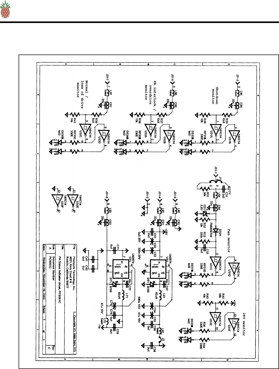
1. 1A0035 STATUS BOARD — Schematic
Page 19
VI — SCHEMATICS AND PARTS LIST

PINEAPPLE TECHNOLOGY, INC.
VTX2KW-A Operating and Service Manual VI — SCHEMATICS AND PARTS LIST
Page 20
VI — SCHEMATICS AND PARTS LIST
C. MFA1KW
1. 1A0035 STATUS BOARD — Parts List
Item Qty P/N Title Detail
AssyTree1A0035 Printed 12/22/2004
1A0035
PA STATUS BOARD
PC9061A
Type
Status
Revision
PL
U
B
User1
User2
User3
User4
User5
Date
By
8/1/2002
RA
PA STATUS BOARDTop 1A0035 PC9061A
RES ARRAY, SMT1 2 114330 330 OHMS
RES CHIP 08052 5 115103 10K OHM SMT 0805
RES CHIP 08053 1 115334 330 K OHM SMT
RES CHIP 08054 1 115563 56K OHM 0805 SM
RES CHIP 08055 3 115682 6.8 K OHM SMT
CAP CHIP 08056 6 21X005 100NF 10% XTR 0805 CASE
CHIP CAP 08057 1 21X008 10NF 50 V 0805 SM
CAP TH POLYPROPYLENE8 1 240109 3N3 600 WVDC .033UF
CAP TAN SMD9 1 240110 3.3 UFD 35 V
CAP TAN SMD10 1 240111 47 UF 10 V TAN
CAP RADIAL TH11 1 241300 330 UF 35 VDC
CAP RADIAL TH12 1 241301 680 UF 10 V ELECTROLYTIC
FT CAP 22N SM13 6 27022N AVX OR MURRATA PART
CON MICRO-FIT HEADER 3.014 1 480500 8 PIN PC MTG
SEMI DIODE SHOTTKEY15 1 520230 1.5 A 60 VDC D-64
SEMI, DIODE DUAL16 1 520275 FMMD6100
HEX SCHMITH TRIG17 2 530350 74HD14
IC SWITCHER SIMPLE18 1 538150 SO8 PAK
IND LED DUAL COLOR19 5 630200 RED/GREEN T1-3/4 CLR
FERRITE BEAD SMT20 8 750001 0805 EMI FERRITE BEAD
IND, W/W21 1 830510 82 UH .58A PWR SMD
PA STAUS BRD22 2 PC9061H FR4 060 1/1 CBR
RES CHIP 080523 2 115331 33O OHM SMT
SEMI ZENER24 1 520120 5.6 V MELF
RES CHIP 080525 1 115683 68K SM
PINEAPPLE TECHNOLOGY, INC.
4021 ALVIS COURT, #6, ROCKLIN, CA 95677
916-315-8338 Fax 916-315-8118
1A0035
1Page 1 o
f
PINEAPPLE TECHNOLOGY, INC.
VTX2KW-A Operating and Service Manual
Page 21
VI — SCHEMATICS AND PARTS LIST
VI — SCHEMATICS AND PARTS LIST
D. V600LDV2 — Block Diagram

PINEAPPLE TECHNOLOGY, INC.
VTX2KW-A Operating and Service Manual VI — SCHEMATICS AND PARTS LIST
Page 22
VI — SCHEMATICS AND PARTS LIST
D. V600LDV2 — Parts List
Item Qty P/N Title Detail
AssyTreeV600LD Printed 12/22/2004
V
600LD
VHF HB 600W LDMOS PA
5 EA VH200LD MODULES
Type
Status
Revision
PL
U
A
User1
User2
User3
User4
User5
Date
By
12/26/2002
RA
VHF HB 600W LDMOS PATop V600LD 5 EA VH200LD MODULES
VH200LD PALLET2 5 1A0032 VHF TV HIGH BAND BB 200W
AMP
MOLEX BRACKET MTG PLATE3 1 MF9126C U600LD ALL
SW THERMAL4 2 310010 140 DEG F N/C
SLED5 1 MF9137E U500L AL
HANDLE6 1 MF9140A U500L ALL
RES PWR 40 W7 4 180040-100R 100 OHM RES
RES PWR 150 W8 2 180150-100R 100 OHM RES
RES PWR 250 W9 1 180250-50T 50 OHM TERM
HW CS STANDOFF10 2 440101 1.0 x .375; Male/Female; 1032
PLATE, ISO/MONT BRD11 1 MF9203 B1 SM 09 AL W/MTG
COVER, REAR U600LD12 1 MF9202B1 SM 09 AL
Shield, PC9050A13 1 MF9206AMU PCB SHIELD MONITOR/ISO BRD
DC ISO/MONITOR CKT14 1 1A0025 REPLACED CB99
HWRD TERM FEED THRU BLK15 1 452001 5 PIN; #10 STUD; 10-16 AWG
HWR TERM BLK COVER16 1 452050 5 PIN COVER W/MTG HWRD
MOLEX RECEPTACLE U600LD17 1 480401 MOLEX 15-06-0061
MOLEX CRIMP TERMINAL U600LD18 3 480473 MOLEX 39-00-0039 FEMALE
COAX CABLE ASSEMBLY19 1 CA5030 ANDREWS ETS1 TO N PANEL
FLG MT
VHF HB 4-WAY COMBINER20 1 PC9060A 060 FR4 PCB
VHF HB 4-WAY SPLITTER21 1 PC9058A FR4 030 PCB
HEAT SINK VH600LD SIDE B22 1 MF9224A AL HS FAB
HEAT SINK SIDE A VH600LD23 1 MF9225A AL HS FAB
COAX CABLE ASSEMBLY24 1 CA5001 RG142 TO N PM FM 4 HOLE FLG
COMBINER PLATE VH600LD25 1 MF9226A 1/4 AL PLATE
PINEAPPLE TECHNOLOGY, INC.
4021 ALVIS COURT, #6, ROCKLIN, CA 95677
916-315-8338 Fax 916-315-8118
V600LD
1Page 1 o
f
PINEAPPLE TECHNOLOGY, INC.
VTX2KW-A Operating and Service Manual VI — SCHEMATICS AND PARTS LIST
Page 23
VI — SCHEMATICS AND PARTS LIST
D. V600LDV2
1. VH200LD — Schematic

PINEAPPLE TECHNOLOGY, INC.
VTX2KW-A Operating and Service Manual
Page 24
VI — SCHEMATICS AND PARTS LIST
VI — SCHEMATICS AND PARTS LIST
D. V600LDV2
1. VH200LD (1A0032) — Parts List
Item Qty P/N Title Detail
AssyTree1A0032 Printed 12/22/2004
1A0032
VH200LD PALLET
VHF TV HIGH BAND BB 200W AMP
Type
Status
Revision
PL
U
C
User1
User2
User3
User4
User5
Date
By
11/25/2002
RA
VH200LD PALLETTop 1A0032 VHF TV HIGH BAND BB 200W
AMP
RES VARI 1/8 W1 4 17L103 10 K OHM SM
RES CHIP 1/8 W3 6 116103 10 K OHM SM 1206
RES CHIP 1/8 W4 4 116101 100 OHM SM 1206
RES CHIP 1W 5 4 11Y2R4 CASE 2512 2.4 OHMS 1W
RES CHIP 1/8 W6 2 116104 100 K OHM SM 1206
RES CHIP 1/87 4 116102 1 K OHM SM 1206
RES CHIP 12068 4 11627R43 27.4K OHM
RES CHIP 12069 1 1165R113 5.11K OHM
THERMISTOR10 1 117333 33K OHM 0603
RES CHIP 120611 1 116561 560 OHM 5% 1206 CASE
RES CHIP 1/8 W13 1 116391 390 OHM SM 1206
RES CHIP 120614 2 116000 0.0 OHMS SM
RES PWR 40 W15 1 180040-100R 100 OHM RES
RES PWR 150 W16 1 180150-100R 100 OHM RES
CAP CHIP 17 10 21Y042 0.1 UF 50 V 1206
CHIP CAP 120618 15 21Y038 470 PF NPO RF CAP
CAP CHIP 080519 3 21X001 100 PF 50V SMD
CAP CHIP ATC20 0 2633R9 3.9 PF B CASE
CAP RADIAL SM21 2 241220 220 UF 50 V HA
CAP RADIAL SM22 1 241010 10UF 16V ALUM ELEC
FT CAP 22N SM23 2 27022N AVX OR MURRATA PART
FERRITE BEAD SMT24 2 750001 0805 EMI FERRITE BEAD
SEMI ZENER25 2 520118 14V MINI 3P MA3140CT
SEMI DIODE GP26 3 520129 1N914 SM SOT-23
SEMI OP-AMP27 1 560108 DUAL OP AMP
VOLTAGE REG SMT28 1 560118 3V LP 50MA SOT-23-5
SEMI GP XSTR29 1 520300 MMBT2222ALT1
SEMI XISTOR30 1 520301 MMBT2907ALT1
FWR FET VHF LINE31 2 530707 125 W 28V LDMOS
PINEAPPLE TECHNOLOGY, INC.
4021 ALVIS COURT, #6, ROCKLIN, CA 95677
916-315-8338 Fax 916-315-8118
1A0032
2Page 1 o
f

PINEAPPLE TECHNOLOGY, INC.
VTX2KW-A Operating and Service Manual VI — SCHEMATICS AND PARTS LIST
Page 25
VI — SCHEMATICS AND PARTS LIST
D. V600LDV2
1. VH200LD (1A0032) — Parts List (cont.)
IND CHIP32 4 822101 100nH SMT 0805
CAP CHIP ATC33 10 263301 300 PF B CASE
CAP CHIP ATC34 2 263750 75 PF B CASE
CAP CHIP ATC35 2 2635R6 5.6 PF B CASE
Z --XFMR 22O MHz VH20036 2 TA220-01 RG179 CUT & TRIM 9.6 IN
Z--XFMT 220 MHz VH200LD37 2 TA220-02 RG316 5.6 IN CUT & TRIM
Z--XFMR 220 MHz VH200LD38 1 TA220-03 RG316 9.6 IN CUT & TRIM
Z-XFMR 220 MHz VH200LD39 4 TA220-20 INS WIRE/SHIELDED 20AWG 4.5
IN
Z-XFMR 220 MHz VH200LD40 4 TA220-30 WIRE/SHIELDED 16 AWG 4.5 IN
Z-XFMR 220 MHz VH200LD41 2 TA220-50 UT85-TP SEMI-RIG COAX 5.6
INCHES
Z-XFMR 220 MHz VH200LD42 1 TA220-51 UT-85-TP SEMI RIG COAX 9.6
INCHES
Z-XFMR 220 MHz VH200LD43 2 TA220-60 UT-85-75-TP SEMI RIG COAX 9.6
INCHES
PCB VH200LD44 1 PC9057C FR4 060 1/1
HW PWR TAP45 2 451070 6-32 STL KEYSTONE 8191
RES CHIP 1 W46 4 11Y100 10 OHM SM 2512
CAP CHIP47 4 21Y041 0.01 UF SM 1206
RES CHIP 1/8 W48 1 116223 22 K OHM SM 1206
RES CHIP 1/8 W49 1 116331 330 OHM SM 1206
RES CHIP 120650 2 1163322 33.2 K OHM 1 %
AssyTree1A0032
Item Qty P/N Title Detail
1A0032
Printed 12/22/2004
Rev C
VH200LD PALLET
VHF TV HIGH BAND BB 200W AMP
PINEAPPLE TECHNOLOGY, INC.
4021 ALVIS COURT, #6, ROCKLIN, CA 95677
916-315-8338 Fax 916-315-8118
1A0032
2Page 2 o
f
PINEAPPLE TECHNOLOGY, INC.
VTX2KW-A Operating and Service Manual
Page 26
VI — SCHEMATICS AND PARTS LIST
VI — SCHEMATICS AND PARTS LIST
D. V600LDV2
1. 1A0025 — Schematic

PINEAPPLE TECHNOLOGY, INC.
VTX2KW-A Operating and Service Manual VI — SCHEMATICS AND PARTS LIST
Page 27
VI — SCHEMATICS AND PARTS LIST
D. V600LDV2
1. 1A0025 — Parts List
Item Qty P/N Title Detail
AssyTree1A0025 Printed 12/22/2004
1A0025
DC ISO/MONITOR CKT
REPLACED CB99
Type
Status
Revision
PL
U
B
User1
User2
User3
User4
User5
Date
By
11/29/2001
RA
DC ISO/MONITOR CKTTop 1A0025 REPLACED CB99
PCB DC ISO/MONT BRD1 1 PC9050C FR4 060
OP-AMP QUAD PAK2 1 560101 TLE2064AID TI
OP-AMP DUAL PAK3 1 560102 8-SOIC
FT CAP 22N SM4 15 27022N AVX OR MURRATA PART
CHIP CAP 08056 1 21X007 47NF 50WVDC X7R
FUSE PICO II EPOXY7 5 472015 15 A 32 VDC
CON DB9 SUB RT ANGLE FM8 1 481250 METAL CASE AMP7457814
TOROID IND9 5 1A0011 10 T #14 ON N40
XISTOR FET BSS8410 5 590010 BSS84ZXCT
RES 5 WATT AXIAL11 5 150R01 0.01 OHM 1.0 %
RES 2W 10 OHM12 5 140010 10 OHM
RES CHIP 080513 5 1151000 100 OHM 1% 0805
RES CHIP 080514 6 1151002 10 K OHM 1% 0805 CASE
RES CHIP 080515 10 1151001 1 K OHM 1 %
HW PWR TAP17 5 451070 6-32 STL KEYSTONE 8191
CON 2 PIN HEADER18 1 480300 AMP A23837-ND
CON 2 PIN PC POST19 1 480310 AMP 640456-2
FERRITE BEAD SMT20 12 750001 0805 EMI FERRITE BEAD
CAP CHIP 080521 7 21X005 100NF 10% XTR 0805 CASE
CHIP CAP 080522 7 21X006 1000 PF 10% 0805 CASE
RES CHIP 080523 1 1154991 4.99K OHM 1% 0805 CASE
RES CHIP 080524 1 115113 11K OHM 1% 0805 CASE
DIODE SWITCH25 1 520260 80V 100MA MINI 3P
CAP RADIAL SMT26 1 240087 4.7 UH 50 VDC
PINEAPPLE TECHNOLOGY, INC.
4021 ALVIS COURT, #6, ROCKLIN, CA 95677
916-315-8338 Fax 916-315-8118
1A0025
1Page 1 o
f

PINEAPPLE TECHNOLOGY, INC.
VTX2KW-A Operating and Service Manual VI — SCHEMATICS AND PARTS LIST
Page 28
VI — SCHEMATICS AND PARTS LIST
E. VS500 4-WAY SPLITTER — Parts List
Item Qty P/N Title Detail
AssyTreeVS500-4 Printed 12/22/2004
V
S500-4
VHF HB 4-WAY N CON
ISO 100 W DIGITAL/ANALOG
Type
Status
Revision
CAT
U
A
User1
User2
User3
User4
User5
Date
By
12/11/2002
RA
VHF HB 4-WAY N CONTop VS500-4 ISO 100 W DIGITAL/ANALOG
BASE PLATE, .5 IN AL1 1 MF9243A VS100D-4, TYPE N CON
CHASSIS SIDES, AL2 1 MF9244A VS100D-4 TYPE N CON
COVER, AL TOP3 1 MF9245A VS100D-4, TYPE N CON
PINEAPPLE TECHNOLOGY, INC.
4021 ALVIS COURT, #6, ROCKLIN, CA 95677
916-315-8338 Fax 916-315-8118
VS500-4
1Page 1 o
f

PINEAPPLE TECHNOLOGY, INC.
VTX2KW-A Operating and Service Manual
Page 29
VI — SCHEMATICS AND PARTS LIST
VI — SCHEMATICS AND PARTS LIST
F. VC2KW COMBINER
INFORMATION
NOT AVAILABLE
PINEAPPLE TECHNOLOGY, INC.
VTX2KW-A Operating and Service Manual VI — SCHEMATICS AND PARTS LIST
Page 30
VI — SCHEMATICS AND PARTS LIST
G. PAS10 & ADP500 MONITOR — Block Diagram

PINEAPPLE TECHNOLOGY, INC.
VTX2KW-A Operating and Service Manual
Page 31
VI — SCHEMATICS AND PARTS LIST
VI — SCHEMATICS AND PARTS LIST
G. PAS10 & ADP500 MONITOR — PAS10 — Parts List
Item Qty P/N Title Detail
AssyTreePAS10 Printed 12/22/2004
PAS10
PA SEL SW FOR ADP500
10 POLE INPUT 1 OUTPUT
Type
Status
Revision
CAT
U
A
User1
User2
User3
User4
User5
Date
By
6/22/2004
RA
PA SEL SW FOR ADP500Top PAS10 10 POLE INPUT 1 OUTPUT
PA SELECTER SWITCH1 1 PC9501 10 POLE ADP500
SW 10 POLE 2 1 483010 ADP500 PA SELECTOR PAS10
CON DB9 SUB RT ANGLE FM3 1 481250 METAL CASE AMP7457814
CON DB9 2 SECTION RT ANG 4 5 481260 PCB MTG 0.9 SPACING
PLATE, FRONT PAS105 1 MF9342X1 W/ PAINT & SILKSCREEN
CHASSIS, PAS106 1 MF9343X1 W/ ALODINE & SILKSCREEN
COVER, TOP PAS107 1 MF9344X1 W/ ALODINE & SILKSCREEN
PINEAPPLE TECHNOLOGY, INC.
4021 ALVIS COURT, #6, ROCKLIN, CA 95677
916-315-8338 Fax 916-315-8118
PAS10
1Page 1 o
f

PINEAPPLE TECHNOLOGY, INC.
VTX2KW-A Operating and Service Manual
Page 32
VI — SCHEMATICS AND PARTS LIST
VI — SCHEMATICS AND PARTS LIST
G. PAS10 & ADP500 MONITOR — ADP500 — Parts List
Item Qty P/N Title Detail
Assy Tree for: ADP500 Printed 12/22/2004
ADP500
DISPLAY PANEL, ANALOG
SEL SW AND METER
Type
Status
Revision
CAT
U
A
User1
User2
User3
User4
User5
Date
By
9/15/2002
RA
DISPLAY PANEL, ANALOGTop ADP500 SEL SW AND METER
ADP1000 LOGIC PCB1 1 1A0029 LOGIC BRD PARTS
ADP1000 FP PCB2 1 1A0030 FP PCB AND PARTS
FUSE 3AG3 1 471306 6 AMP
FUSE HOLDER PANEL MTG4 1 460150 3AG TYPE QC CON
SW, ON/OFF ROCKER AC5 1 484001 CW IND. NAA-211-B121-00
METER, 2 VOLTS FS6 1 660103 SELCO 39M-0-2VDC
PWR MONITOR CK7 1 1A0027 PC9052B CBR
POWER SUPPLY OPEN/FRAME8 1 PS2527 110/220 VAC 27 V 25 W
TOGGEL SW MOMENTARY/ON9 1 484020 2 POLE
PINEAPPLE TECHNOLOGY, INC.
4021 ALVIS COURT, #6, ROCKLIN, CA 95677
916-315-8338 Fax 916-315-8118
ADP500
1Page 1 o
f
PINEAPPLE TECHNOLOGY, INC.
VTX2KW-A Operating and Service Manual
VI — SCHEMATICS AND PARTS LIST
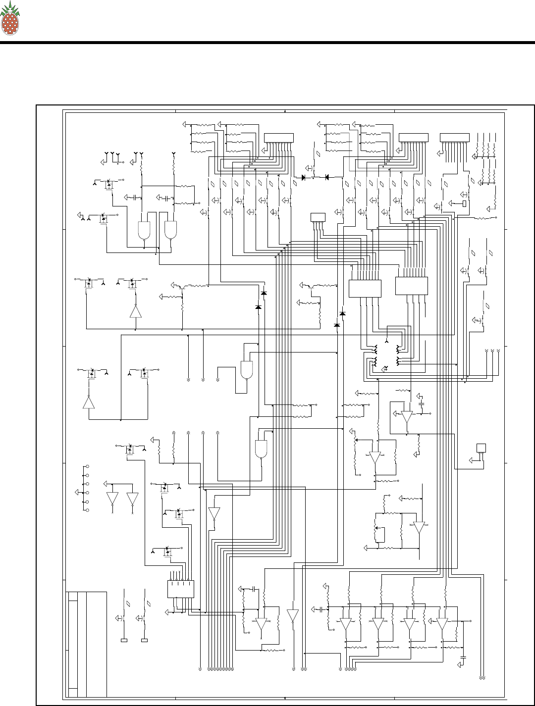
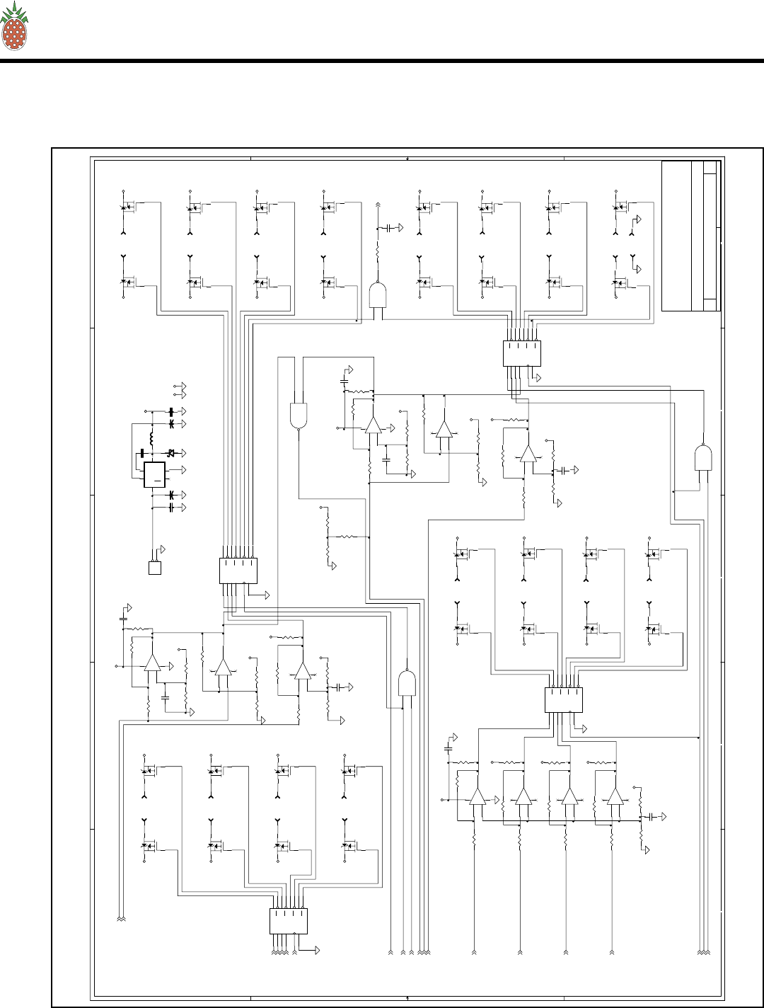
G. PAS10 & ADP500 MONITOR
1. 1A0029 — Schematic 1 of 4
VI — SCHEMATICS AND PARTS LIST
Page 33
5
5
4
4
3
3
2
2
1
1
DD
CC
BB
AA
+Va
+Va
+Va
+Va
+Va
+5V
MON_3
MON_2
MON_1
Title
Size Document Number R e v
Date: Sheet
o f
PC9055 D
RF Power Monitor Circuit
Pineapple Technology Inc.
4021 Alvis Court, Unit 6
Rocklin, California 95677
A
4 4Thursday, November 04, 2004
Sample Connect
+5V
DRAWN BY: ECLIPSE
R140 27k
D97
HSMS2802
+
C106
2u2 16V
R163
100e
R146
51e
R170
100k
C99
47n
J5 1
C96
47n
L52
0u58
R153
0e0 Q3
MMBT2222A
R148
100k
C91 47n
J4 1
+-
R149100k
+
-
U53B
LM358
5
6
7
C105
39p
+-
R15110k
R141 10k
C93
2n2
R169
1M0
D96 HSMS2802
+ -
R167
1k0
R157
100k
Q4
MMBT2222A
R154
1k
R138 1k0
C98
47n
C89
39p
R164
1k0
R147
1M0
R166 0e0
C88 47n
L53
0u58
+
C104
10u 10V
R145
100k
R155
1k
R159
1M0
R158
100k
L54 bead
+
C90
2u2 16V
+ -
R144
1k0
+
-
U53A
LM358
3
2
1
PAD2
GND_PAD
1
R162
100e
R160
1k
PAD1
GND_PAD
1
R150 2k7
J3 1
R139
1K
C92
2n2
R165 930
R1421k0
R143 0e0
+
C97
4u7 16V
R161
1k
C101
47n
C102
47n
C95 47n
D95 HSMS2802
R168
51e
+
-
U52A
LM358
3
2
1
C94 47n
+
-
U52B
LM358
5
6
7
R152 56k
R137
51e
C103
47n
+ -
R156
1k0
C100 47n

PINEAPPLE TECHNOLOGY, INC.
VTX2KW-A Operating and Service Manual
VI — SCHEMATICS AND PARTS LIST
G. PAS10 & ADP500 MONITOR
1. 1A0029 — Schematic 2 of 4
Page 34
VI — SCHEMATICS AND PARTS LIST
5
5
4
4
3
3
2
2
1
1
DD
CC
BB
AA
VDD
+5V
+5V
+5V +5V
+5V +5V +5V
+5V
+5V +5V
+5V
+5V
+5V +5V
+5V +5V
+5V
+5V +5V
+5V +5V
+5V
+5V
+5V
+5V
LTCH_LED
SHUTDWN
ANTFLT
TEMPFLT
ISOFLT
PSFLT
/VIDOFF
CTRRES
Title
Size Document Number Rev
Date: Sheet o f
PC9055 D
ADP1000 CONTROL BOARD - LOGIC MODULE
Pineapple Technology Inc.
4021 Alvis Court, Unit 6
Rocklin, California 95677
B
3 4Thursday, November 04, 2004
Drawn By: = ECLIPSE
Inhibit
Connector
RETRY TIMER
BYPASS CAPS FOR:
SHUTDOWN VALID TIME = 7.8 SEC
OPEN=RESET AT U23 TIMEOUT
FREQ=460Hz
13,15,16,17,18,19,20,21,
RETRY TIMEOUT
U1,2,5,7,8,9,10,11,
8 RETRY
22,23,24
OPEN=INF RETRY
16 RETRY
TIME DELAY TO FAULT VALID = 1.1 SEC
FREQ=4.6Hz
C45
.1U
12
C31
.1U
12
U20A
MC14013
D
5
CLK
3
Q1
Q2
S6
R
4
U17D
CD4049
910
R101
0 OHM
12
U18D
MC14011
12
13
11
14
C41
.1U
12
U16D
MC14071
12
13
11
U22A
MC14071
1
2
3
J2-15
15
U17A
CD4049
32
U24B
MC14013
D
9
CLK
11
Q13
Q
12
S8
R
10
C43
.1U
12
C49
.1U
1
2
C44
.1U
12
R107
120K
12
D92
MMBD914L_0
AC
C30
.1U
12
U17B
CD4049
5
4
U16B
MC14071
5
6
4
J2-16
16
R103
4.7K
12
JP2
HEADER 1
1
C34
.1U
12
R110
100K
12
U18B
MC14011
5
6
4
14
U17E
CD4049
11
12
C42
.1U
12
R106
56K
12
U17F
CD4049
14 15
R119
1M
12
C39
.1U
1
2
U22B
MC14071
5
6
4
R102
NO_LOAD
12
R108
0 OHM
12
JP8
HEADER 2
1
1
2
2
U20B
MC14013
D
9
CLK
11
Q13
Q12
S8
R
10
JP9
HEADER 2
1
1
2
2
U23
MC14060
PI
11
RST
12
Q4 7
Q5 5
Q6 4
Q7 6
Q8 14
Q9 13
Q10 15
Q12 1
Q13 2
Q14 3
PO 9
PO 10
R99
NO_LOAD
12
C46
.1U
12
+
C24
10U
U16C
MC14071
8
9
10
C76
.1U
12
U22C
MC14071
8
9
10
R111
100
12
C36
.1U
12
U24A
MC14013
D
5
CLK
3
Q1
Q
2
S6
R
4
C50
.1U
12
C32
.1U
12
U18C
MC14011
8
9
10
14
U21
MC14024
CLK
1
RST
2
Q1 12
Q2 11
Q3 9
Q4 6
Q5 5
Q6 4
Q7 3
C47
.1U
12
C29
.1U
12
C26
.1U
12
C33
.1U
12
C37
.1U
12
R118
470K
12
C25
.01U
12
R100
NO_LOAD
1
2
U19
MC14060
PI
11
RST
12
Q4 7
Q5 5
Q6 4
Q7 6
Q8 14
Q9 13
Q10 15
Q12 1
Q13 2
Q14 3
PO 9
PO 10
C38
.1U
12
U18A
MC14011
1
2
3
14
R104
NO_LOAD
12
R109
NO_LOAD
12
R128
10K
1
2
U22D
MC14071
12
13
11
R130
10K
1
2
R105
220K
12
U16A
MC14071
1
2
3
R127
3.01K
12
C48
.01U
12
U17C
CD4049
7
6
R129
100K
12
C40
.1U
12
C35
.1U
12
PINEAPPLE TECHNOLOGY, INC.
VTX2KW-A Operating and Service Manual
VI — SCHEMATICS AND PARTS LIST
G. PAS10 & ADP500 MONITOR
1. 1A0029 — Schematic 3 of 4
Page 35
VI — SCHEMATICS AND PARTS LIST
5
5
4
4
3
3
2
2
1
1
DD
CC
BB
AA
LC4
LC6
LC5
EXPIN
RES4
RES5
RES1
RES2
RES3
EXPOUT
EXPIN EXPOUT
LC6
LC1
LC3
LC2
LC3
LC5
LC4
LC1
LC2
RES1 RES2
RES3
LC3
LC1
LC5
LC6
RES4
LC2
RES5
LC4
+5V
+5V
+5V
+5V
+5V
+5V
+5V
+5V
+5V
+5V
+5V
+5V
+5V
+5V
+5V
+5V
+5V
+5V
+5V
+5V
+5V +5V
+5V
+5V
+5V
+5V
OP10
OP12
OP13
OP14
OP15
OP16
OP17
OP18
OP11
OP20
OP1
OP2
OP3
OP4
OP5
OP6
OP7
OP8
OP9
MON_1
MON_2
MON_3
OP19
ISOFLT
ANTFLT
PSFLT
LTCH_LED
TEMPFLT
SHU TDW N
/VIDOFF
Title
Size Doc ument Num ber R e v
Da te: Sheet o f
PC9055 D
ADP1000 CONTROL BOARD
Pineapple Technology Inc.
4021 Alvis Court, Unit 6
Rocklin, California 95677
C
1 4Thursday, November 04, 2004
Dra wn B y: = ECLIPSE
AUX
AUX2A
RESET
PA4
PA2
VSWR FLT
/ISO FLT
RED
RF PWR OFF
RED
GRN
/ISO FLT
GRN
PA1
A2
PA3
RED
GRN
VIDEO OFF
VPS
TO EXPANDED SCALE CKT
HIGH=ZERO INPUTS
VPS
PA5
A1 SELECT
/VID FLT
METER
Pa
Po
A1 SELECT GRN
A2 SELECT
A2 SELECT
GRN
PA5
A1
AUX1B
/TMP FLT
PA6 FLT
ANT VSWR
SET
SHUTDOWN
/TMP FLT
Note: Rotary SW pin#1=PA1,
then follows order on front
panel dwg.
PA2
Meter
Calibrate
Pr
PA6
RED
PA1
AUX2B
AUX1A
PA4
PA3
GRN
NOTE: DO NOT STUFF R171 THRU R194 RESISTORS
C10
FT
1
2
3
C2
.1U
1
2
U9F
CD4049
14
15
F15
FERRITE BEAD
JP3
9-PIN "D"
8
3
7
2
6
1
9
5
4
F4
FERRITE BEAD
J2-23
23
R186
10K
1
2
JP4
9-PIN "D"
8
3
7
2
6
1
9
5
4
C15
FT
12
3
J2-18
18
D50
IRLML5103
D
G
S
R59
10K
1
2
R25
1K
1
2
R113
NO_LOAD
1
2
R114
10K
12
F20
FERRITE BEAD
PD2
Pad
1
R58
22K
1
2
R32
1K
AB
W
J2-32
32
R188
10K
12
Q1
MMBT2222A
C
E
B
C23
.1U
1
2
R183
10K
12
J2-26
26
J2-14
14
R124
1.60K
1
2
C3
FT
12
3
PD3
Pad
1
C17
FT
1
2
3
J2-19
19
F9
FERRITE BEAD
F22
FERRITE BEAD
R193
10K
12
J2-4
4
R20
10K
12
F3
FERRITE BEAD
R42
4.7K
12
C4
FT
12
3
R33
3.9K
1
2
J2-30
30
C85
FT
12
3
MNT3
1
D40
IRLML5103
D
G
S
J2-5
5
R187
10K
12
U9A
CD4049
3
2
R8
1K
1
2
F23
FERRITE BEAD
R173 10K
1
2
C18
FT
1
2
3
U8C
MC14011
8
9
10
14
C8
FT
12
3
C71
FT
12
3
R123
4.7K
12
D68
MMBD914L
A
C
R176 10K
1
2
F16
FERRITE BEAD
+
-
U4C
LM339
9
8
14
3
12
R15
100K
1
2
D93
MMBD914L
A
C
J2-12
12
MNT1
1
C11
FT
1
2
3
F12
FERRITE BEAD
R26
1K
1
2
+
-
U3B
LM358
5
6
7
8
4
R175 10K
1
2
MNT6
1
J2-24
24
JP6
9-PIN "D"
8
3
7
2
6
1
9
5
4
C12
FT
12
3
R184
10K
12
R56
4.7K
12
R117
10K
12
U11
MC14042
D0 4
D1 7
D2 13
D3 14
CLK 5
POL 6
Q0
2
Q0
3
Q1
10
Q1
9
Q2
11
Q2
12
Q3
1
Q3
15
R57
10K
1
2
D25
IRLML5103
D
G
S
R34
1K
1
2
F10
FERRITE BEAD
J2-21
21
R115
10K
1
2
F5
FERRITE BEAD
U8A
MC14011
1
2
3
14
+
-
U6D
LM339
11
10
13
3
12
R185
10K
1
2
F24
FERRITE BEAD
J2-13
13
C14
FT
1
2
3
R39
10
1
2
R60
100
12
J2-9
9
R192
10K
12
U2
MC14551
W0
15
W1
1
X0
2
X1
3
Y0
6
Y1
10
Z0
11
Z1
12
CTL
9
W14
X4
Y5
Z13
MNT4
1
R120
NO_LOAD
1
2
PD1 Pad
1
R122
10.0K
12
R30
10K
12
C5
FT
1
2
3
C79
.1U
1
2
F21
FERRITE BEAD
+
-
U14D
LM339
11
10
13
3
12
R182
10K
12
R190
10K
12
R48
1K
1
2
R43
10K
1
2
F17
FERRITE BEAD
R21
10K
12
D64
IRLML5103
D
G
S
+
-
U4A
LM339
7
6
1
3
12
R191
10K
1
2
J2-34
34
J2-29
29
F13
FERRITE BEAD
J2-8
8
R121
25.5K
1
2
D94
MMBD914L
AC
R131
10K
1
2
R41
51.1K
1
2
J2-11
11
U8D
MC14011
12
13
11
14
R18
1M
1
2
F25
FERRITE BEAD
R178 10K
1
2
J2-1
1
D62
IRLML5103
D
G
S
R112
0 OHM
1
2
D61
IRLML5103
D
G
S
+
-
U4D
LM339
11
10
13
3
12
C78
.1U
12
J2-10
10
D66
MMBD914L
A
C
R125
2K
AB
W
F7
FERRITE BEAD
R51
1.00K
1
2
R5
10K
1
2
F1
FERRITE BEAD
U1
MC14551
W0
15
W1
1
X0
2
X1
3
Y0
6
Y1
10
Z0
11
Z1
12
CTL
9
W14
X4
Y5
Z13
R180
10K
12
R19
1M
1
2
R177 10K
1
2
JP5
HEADER 4
1
2
3
4
J2-25
25
R179
10K
12
C9
FT
12
3
+
-
U3A
LM358
3
2
1
8
4
C82
FT
1
2
3
MNT2
1
U9E
CD4049
11
12
R29
1M
1
2
C87
FT
1
2
3
R47
10K
12
D67
MMBD914L
A
C
R132
100K
12
U9D
CD4049
910
F18
FERRITE BEAD
C7
FT
1
2
3
R50
10
1
2
U9B
CD4049
5
4
Q2
MMBT2222A
C
E
B
R14
1K
1
2
U8B
MC14011
5
6
4
14
J2-22
22
R52
32.4K
1
2
C27
.1U
12
J2-6
6
F14
FERRITE BEAD
C19
FT
12
3
R4
1M
1
2
C84
FT
12
3
D51
IRLML5103
D
G
S
R194
10K
12
J2-28
28
D65
MMBD914L
A
C
R133
100K
1
2
F11
FERRITE BEAD
C83
FT
12
3
C13
FT
1
2
3
R181
10K
1
2
R189
10K
12
R40
1.00K
1
2
R116
10K
12
C86
FT
12
3
C22
.1U
1
2
C16
FT
12
3
+
-
U4B
LM339
5
4
2
3
12
J2-33
33
JP1
HEADER 2
11
22
J2-2
2
R174 10K
1
2
J2-17
17
J2-31
31
D39
IRLML5103
D
G
S
J2-7
7
F8
FERRITE BEAD
R13
10K
1
2
F2
FERRITE BEAD
D49
IRLML5103
D
G
S
D63
IRLML5103
D
G
S
C72
FT
12
3
R69
100
12
J2-27
27
R172 10K
1
2
R12
1M
1
2
R46
1M
1
2
F19
FERRITE BEAD
J2-3
3
MNT5
1
R171 10K
1
2
U9C
CD4049
76
PINEAPPLE TECHNOLOGY, INC.
VTX2KW-A Operating and Service Manual
Page 36
VI — SCHEMATICS AND PARTS LIST
VI — SCHEMATICS AND PARTS LIST
G. PAS10 & ADP500 MONITOR
1. 1A0029 — Schematic 4 of 4
5
5
4
4
3
3
2
2
1
1
DD
CC
BB
AA
+5V
+5V
+5V
+5V
+5V
+5V
VSS VEE
+5V
+5V
+5V
+5V
+5V
+5V
+5V
+5V
+5V
+5V
+5V
+5V
+5V
+5V
+5V
+5V
+5V
+5V
+5V
+5V
+5V
+5V
+5V
+5V
+5V
+5V
+5V
+5V
+5V
+5V
+5V
+5V
+5V
+5V
+5V
+5V
+5V
+5V +5V
+5V
+5V
+5V
+5V
OP1
OP2
OP3
OP4
OP5
OP6
OP7
OP19
OP8
OP9
OP10
OP11
OP12
OP13
OP14
OP15
OP16
OP17
OP18
OP20
CTR RES
Title
Size Doc ument Num ber R e v
Da te: Sheet o f
PC9055 D
ADP1000 CONTROL BOARD
Pineapple Technology Inc.
4021 Alvis Court, Unit 6
Rocklin, California 95677
C
2 4Thu rsday, N ovem ber 0 4, 2004
Dra wn B y: = ECLIPSE
HI SET
GRNRED
RED
GRN
RED
RED
GRN
GRN
A1-PA1
A1-PA2
A1-PA3
A1-PA4
A2-PS
A2-TEMP
A2-PA5
RED
A2-ISO
GRN
GRN
GRNRED
GRNRED
GRNRED
RED
GRN
A1-PS
A1-PA5
A1-ISO
RED
RED
A1-TEMP
GRN
GRN
A1-PA4
RED
RED
RED
GRN
GRN
A1-PA3
RED
A1-PA1
A1-PA2
RED GRN
GRN
LO SET
HI SET
LO SET
DC INPUT
R92
1.00K
1
2
J1-21
21
+
C110
680u 10V
R136
22K
1
2
C108
47n
+
-
U14C
LM339
9
8
14
3
12
R81
10K
12
D98 B140
J1-7
7
R74
3.01K
1
2
R55
1K
1
2
J1-33
33
D42
IRLML5103
D
G
S
J1-2
2
R1
1M
1
2
JP7
HEADER 2
11
22
R7
22.1K
1
2
D14
IRLML5103
D
G
S
R65
1K
1
2
C107
47n
J1-28
28
J1-24
24
U13
MC14042
D0
4
D1
7
D2
13
D3
14
CLK
5
POL
6
Q0 2
Q0 3
Q1 10
Q1 9
Q2 11
Q2 12
Q3 1
Q3 15
R16
1k82
1
2
R53
1M
1
2
D44
IRLML5103
D
G
S
C73
.01U
12
D4
IRLML5103
D
G
S
R71
10K
12
J1-10
10
R63
10.0K
1
2
R62
10K
1
2
J1-1
1
R87
1K
1
2
U10B
MC14011
5
6
4
14
J1-29
29
+
C109
330u 35V
J1-23
23
R75
1M
1
2
D34
IRLML5103
D
G
S
D55
IRLML5103
D
G
S
+
-
U6C
LM339
9
8
14
3
12
D19
IRLML5103
D
G
S
J1-18
18
R73
1k82
1
2
R35
1.00K
1
2
D2
IRLML5103
D
G
S
R88
1.00K
1
2
D5
IRLML5103
D
G
S
L55
82uH
J1-9
9
J1-11
11
+
-
U12C
LM339
9
8
14
3
12
R89
51.1K
1
2
D29
IRLML5103
D
G
S
U5
MC14042
D0
4
D1
7
D2
13
D3
14
CLK
5
POL
6
Q0 2
Q0
3
Q1 10
Q1 9
Q2 11
Q2 12
Q3 1
Q3 15
J1-4
4
R61
1M
1
2
R66
1M
1
2
J1-30
30
U10A
MC14011
1
2
3
14
R3
1K
1
2
R2
10K
12
C75
.01U
12
J1-17
17
R64
22.1K
1
2
D35
IRLML5103
D
G
S
U10C
MC14011
8
9
10
14
D8
IRLML5103
D
G
S
D27
IRLML5103
D
G
S
D10
IRLML5103
D
G
S
J1-14
14
D1
IRLML5103
D
G
S
U10D
MC14011
12
13
11
14
+
-
U6A
LM339
7
6
1
3
12
D22
IRLML5103
D
G
S
J1-3
3
R80
1K
1
2
J1-12
12
D23
IRLML5103
D
G
S
R134
1.60K
1
2
J1-32
32
U15
MC14042
D0
4
D1
7
D2
13
D3
14
CLK
5
POL
6
Q0 2
Q0
3
Q1 10
Q1 9
Q2 11
Q2
12
Q3 1
Q3
15
R83
1K
1
2
C74
.1U
1
2
J1-20
20
R28
1K
1
2
+
-
U12B
LM339
5
4
2
3
12
R72
1K
1
2
C77
.1U
12
D20
IRLML5103
D
G
S
C1
.1U
12
J1-16
16
R70
1M
1
2
J1-6
6
R79
1M
1
2
J1-13
13
R27
10K
12
J1-26
26
+
-
U12D
LM339
11
10
13
3
12
J1-31
31
J1-19
19
R6
10.0K
1
2
C81
.1U
12
R85
10K
12
D33
IRLML5103
D
G
S
U7
MC14042
D0
4
D1
7
D2
13
D3
14
CLK
5
POL
6
Q0 2
Q0
3
Q1 10
Q1 9
Q2 11
Q2 12
Q3 1
Q3 15
C20
.1U
1
2
C111
47n
R135
3.32K
1
2
+
-
U12A
LM339
7
6
1
3
12
J1-5
5
D16
IRLML5103
D
G
S
U54
LM2674
fb 4
cb 1
sw 8
in
7
shdn
5
gnd
6
D45
IRLML5103
D
G
S
+
-
U14B
LM339
5
4
2
3
12
D7
IRLML5103
D
G
S
R93
51.1K
1
2
J1-15
15
J1-25
25
D30
IRLML5103
D
G
S
+
-
U6B
LM339
5
4
2
3
12
J1-22
22
+
-
U14A
LM339
7
6
1
3
12
D43
IRLML5103
D
G
S
D28
IRLML5103
D
G
S
C80
.1U
1
2
R84
1M
1
2
D36
IRLML5103
D
G
S
R17
3.01K
1
2
D52
IRLML5103
D
G
S
R23
1M
1
2
D17
IRLML5103
D
G
S
R9
1M
1
2
R126
100K
1
2
J1-8
8
C21
.1U
12
D54
IRLML5103
D
G
S
J1-34
34
D53
IRLML5103
D
G
S
R76
10K
12
D13
IRLML5103
D
G
S
R54
10K
1
2
R36
51.1K
1
2
D11
IRLML5103
D
G
S
J1-27
27

PINEAPPLE TECHNOLOGY, INC.
VTX2KW-A Operating and Service Manual
Page 37
VI — SCHEMATICS AND PARTS LIST
VI — SCHEMATICS AND PARTS LIST
G. PAS10 & ADP500 MONITOR
1. 1A0029 — Parts List
Item Qty P/N Title Detail
Assy Tree for: 1A0029 Printed 12/22/2004
1A0029
ADP1000 LOGIC PCB
LOGIC BRD PARTS
Type
Status
Revision
PL
U
A
User1
User2
User3
User4
User5
Date
By
1/5/2002
RA
ADP1000 LOGIC PCBTop 1A0029 LOGIC BRD PARTS
ADP1000 LOGIC BOARD1 1 PC9055 PC9055 REV D INTEGRATED
LOGIC IC MC140132 2 560320 DUAL D F/F SOT 14
LOGIC IC MC14011BD3 3 560315 LOG CMOS GATE NAND QUAD
LOGIC IC MC14042BD 16 PIN4 5 560325 LOG CMOS LATCH QUAD TRAN
LOGIC IC MC14060BD5 2 560310 CTR/DRIVER IC SOT 16
IC HEX INV BUFFER6 2 539100 CD4049UBCM
LOGIC IC MC14071BD7 2 560330 LOG CMOS GATE OR QUAD
SO14
IC DIF AMP QUAD8 4 539000 LM339DR SO14
SEMI OP-AMP9 1 560108 DUAL OP AMP
ANALOG MC14551BD10 2 562500 MUX/DE-MUX 2 CHANNEL
IC SWITCHER/REG LM2674M-5.011 1 538100 28 V IN 5 VOLTS OUT 500MA
LOGIC IC CD4024BM12 1 539110 7 STAGE COUNTER SO14
RES CHIP 120613 2 11622R13 22.1K OHM SMT
RES 0805 CASE14 4 1155112 51.1 K OHM 1%
RES 0805 CASE15 1 1153242 32.4 K OHM 1%
SEMI GP XSTR16 2 520300 MMBT2222ALT1
DIODE HEX FET P17 42 520272 HEX FET SOT-3
IND, W/W18 1 830510 82 UH .58A PWR SMD
SEMI DIODE GP19 4 520129 1N914 SM SOT-23
RES CHIP 1/8 W21 17 116105 1 M OHM SM 1206
RES CHIP 1/8 W22 27 116103 10 K OHM SM 1206
RES CHIP 1/823 14 116102 1 K OHM SM 1206
CAP CHIP 24 36 21Y042 0.1 UF 50 V 1206
FT CAP 22N SM25 18 27022N AVX OR MURRATA PART
FERRITE BEAD SMT26 18 750001 0805 EMI FERRITE BEAD
CAP RADIAL TH27 1 241310 680 UF 35 WVDC AL
ELECTROLYTIC
CAP RADIAL TH28 1 241320 1200 UF 10 WVDC AL
ELECTROLYTIC
CAP SM 1206 CASE29 1 240200 10 UF 10 WVDC
CAP CHIP30 4 21Y041 0.01 UF SM 1206
PINEAPPLE TECHNOLOGY, INC.
4021 ALVIS COURT, #6, ROCKLIN, CA 95677
916-315-8338 Fax 916-315-8118
1A0029
2Page 1 o
f

PINEAPPLE TECHNOLOGY, INC.
VTX2KW-A Operating and Service Manual
Page 38
VI — SCHEMATICS AND PARTS LIST
VI — SCHEMATICS AND PARTS LIST
G. PAS10 & ADP500 MONITOR
1. 1A0029 — Parts List (cont.)
CAP SM 120631 3 21Y022 47 NF 50 V
RES CHIP 120632 1 1163321 3.32 K OHM 1%
RES CHIP 120633 1 1162252 25.5K OHM 1206 CASE
RES CHIP 120634 1 116474 470K OHM 1/8 W
RES CHIP 1206 CASE35 1 116124 120 K OHM 5%
RES CHIP 1206 CASE36 1 116563 56K OHM 5%
CHIP RES 120637 1 116224 220 K OHM 1206 CASE 5%
RES CHIP 120638 3 116000 0.0 OHMS SM
CHIP RES 120639 7 116XXX +++NO LOAD+++
RES CHIP 1/8 W40 3 116101 100 OHM SM 1206
RES CHIP 1/8 W41 2 116223 22 K OHM SM 1206
RES CHIP 1/8 W42 2 116100 10 OHM SM 1206
RES CHIP 120643 3 1163011 3.01K OHM 1206 CASE
RES CHIP 120644 4 116472 4.7K OHM 1/8 W SMT
RES CHIP 1/8 W45 1 116392 3.9 K OHM SM 1206
RES CHIP 120646 4 116162 1.6K OHM 5% 1206 CASE
RES CHIP 1/8 W47 6 116104 100 K OHM SM 1206
RES VAR 12 TURN48 1 17L102XT 1K SMT POT 12 TURN
CON HEADER 0.1 CTRS49 2 480600 PROTECTED HEADER 34 PIN
HEADER 10 PIN TH50 1 485001 AMP 0.1 CTR 103308-1
CON 2 PIN PC POST51 2 480310 AMP 640456-2
CON 4 PIN PC LOCKING POST52 1 480320 MOLES MALE
SEMI DIODE SHOTKEY53 1 520212 40V 1A
CON DB9 SUB RT ANGLE FM54 3 481250 METAL CASE AMP7457814
Assy Tree for: 1A0029
Item Qty P/N Title Detail
1A0029
Printed 12/22/2004
Rev A
ADP1000 LOGIC PCB
LOGIC BRD PARTS
PINEAPPLE TECHNOLOGY, INC.
4021 ALVIS COURT, #6, ROCKLIN, CA 95677
916-315-8338 Fax 916-315-8118
1A0029
2Page 2 o
f

PINEAPPLE TECHNOLOGY, INC.
VTX2KW-A Operating and Service Manual
Page 39
VI — SCHEMATICS AND PARTS
VI — SCHEMATICS AND PARTS LIST
G. PAS10 & ADP500 MONITOR
1. 1A0030 — Parts List
Item Qty P/N Title Detail
Assy Tree for: 1A0030 Printed 12/22/2004
1A0030
ADP1000 FP PCB
FP PCB AND PARTS
Type
Status
Revision
PL
U
A
User1
User2
User3
User4
User5
Date
By
1/5/2002
RA
ADP1000 FP PCBTop 1A0030 FP PCB AND PARTS
ADP1000 DISPLAY BRD1 1 PC9054A FR4 060 1/1 CRB
SW, 12 POS ROTOR2 1 483001 SIG SEL SW ADP1000
SW, MOMENTARY PB3 3 484050 OMRON B3WN-6002
RES 1/4W AXIAL TH4 22 150330 1.4 W 330 OHM TH AXIAL
IND LED DUAL COLOR5 22 630200 RED/GREEN T1-3/4 CLR
CON HEADER 0.1 CTRS6 2 480600 PROTECTED HEADER 34 PIN
PINEAPPLE TECHNOLOGY, INC.
4021 ALVIS COURT, #6, ROCKLIN, CA 95677
916-315-8338 Fax 916-315-8118
1A0030
1Page 1 o
f
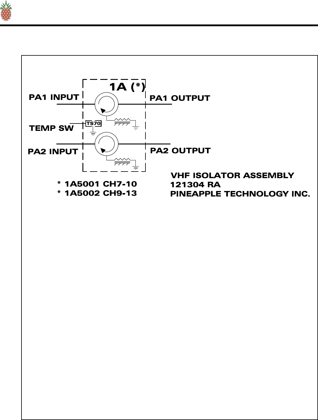
PINEAPPLE TECHNOLOGY, INC.
VTX2KW-A Operating and Service Manual
VI — SCHEMATICS AND PARTS LIST
H. 1A5001/2 ISOLATOR ASSEMBLY
VI — SCHEMATICS AND PARTS
Page 40

PINEAPPLE TECHNOLOGY, INC.
VTX2KW-A Operating and Service Manual
VI — SCHEMATICS AND PARTS LIST
H. 1A5001/2 ISOLATOR ASSEMBLY — Parts List
VI — SCHEMATICS AND PARTS
Item Qty P/N Title Detail
Assy Tree for: 1A5001/2 Printed 12/22/2004
1A5001/2
2-WAY ISOLATOR ASSEMBLYLIT
VHF HB 2KW TWO BAND SPLIT
Type
Status
Revision
PL
U
A
User1
User2
User3
User4
User5
Date
By
12/12/2004
RA
2-WAY ISOLATOR ASSEMBLYLITTop 1A5001/2 VHF HB 2KW TWO BAND SPLIT
500 W TERMINATION1 2 U500T TYPE N CONNECTOR
CIR TYPE N 172-200 MHz2 2 CT-1682-N VHF HB 600 W TYPE N
CIR TYPE N 190-220 MHz3 2 CT-1683-N VHF HB 600 W TYPE N
SW THERMAL4 1 310013 Thermostat; Auto Reset; 1/2" disc
PINEAPPLE TECHNOLOGY, INC.
4021 ALVIS COURT, #6, ROCKLIN, CA 95677
916-315-8338 Fax 916-315-8118
1A5001/2
1Page 1 o
f
Page 41

PINEAPPLE TECHNOLOGY, INC.
VTX2KW-A Operating and Service Manual
Page 42
VII — ROUTINE MAINTENANCE
VII — ROUTINE MAINTENANCE
The following KEY MAINTENANCE AND PERFORMANCE CHECKS should be made monthly or
more frequently in some environments where dust is a problem:
TRANSMITTER
• Remove and clean the air filters with a light detergent and dry completely before re-installing. Dirty
filters will cause PA amps to shutdown resulting in a loss of RF Power. Spare filter P/N 990199 is
available from Pineapple Technology Inc.
• Check and record the Voltage and Current meter readings on the ACDIS2 (AC AND DC DISTRIBU-
TION UNIT LOCATED NEAR THE POWER SUPPLIES). NOTE: current readings will vary with
picture content.
• Using the ADP500 & PAS10 record the bias level settings on each PA Pallet by selecting the appropri-
ate PA with the selector switch. To make this measurement of BIAS ONLY it is necessary to activate
the PA INHIBIT switch momentarily for each reading.
• Using the ADP500 check and record the RF Output power level to insure that it is still reading 100%
+/- 10% from the previous settings.
• Using the ADP500 check and record the VSWR (Reflected power) to insure that it is still reading only a
few percent indicating normal load operations.
• Using the ADP500 check and record Aural power readings. This is normally set at 10% of P-Sync.
Expect this to vary only a few percent from reading to reading.
• Carefully inspect RF Output coax and coaxial fittings for excessive heating or discoloration
FACILITIES
• Clean all air inlet filters and exhaust outlets to insure that the transmitter is getting clean unobstructed
air flow.
• Perform recommended service on air condition systems
• Rodent traps or baits should be renewed to keep the facilities clear of these pests which can damage to
the transmitter

PINEAPPLE TECHNOLOGY, INC.
VTX2KW-A Operating and Service Manual
Page 43
VIII — ADJUSTMENTS AND TUNING
VIII — ADJUSTMENTS AND TUNING
The VTX2KWA is basically a broadband transmitter with a few frequency selective sub-assemblies which
comply with FCC Type Certification requirements. A list of these sub-assemblies are listed below and fol-
lowed by general instructions where applicable:
A. MODULATOR Instructions for making adjustments to the modulator are included in the Manufac-
turer’s Instruction Manual
B. BPV2KW Band Pass filter comes adjusted to the channel as purchased. To change frequency would
require a tuning adjustment to the filter. To perform this adjustment it is necessary to use a NET-
WORK ANALYZER and a signal generator with necessary I/O Adaptors to connect to the filter. The
Technician performing this adjustment should be skilled in tuning Band Pass Filters. If the target
frequency is outside of the tuning range of the filter, it becomes necessary to purchase a new filter.
Replacement filters and service is available from Pineapple Technology Inc.
C. V600LDV2 POWER AMPLIFIER MODULE: The V600LDV2 has three areas where adjustments
may be necessary over time or in the event of a frequency change. These areas are:
1. Bias adjustments: The LDMOS FET devices used in these pallet amplifiers are set to 500ma/
device side or a total of 1 amp/device. This adjustment can be made on the bench by first termi-
nating the input and output with 50 ohm terminations. Apply 31 volts DC to the PA using a power
supply that can provide a minimum of 15 amps. Note: a cooling fan will be necessary to cool the
amplifier during this adjustment.
To adjust biases it is best to turn all the bias adjust resistors CCW or to minimum on the pallet
being adjusted. Using a clamp on DC AMP Meter connected to the DC Feed terminal located on
the DC ISOLATION AND CURRENT MONITOR BOARD measure the current levels. The first
resistor is increased to 500ma indicated on the Amp meter. Repeat this adjustment for each addi-
tional resistor for reading of 1.0 A, 1.5 A, and 2.0 A. This will indicate that each device half is set
to 500 ma.
This concludes the bias adjustment procedure. This adjustment should be made at all time when
a device has to be replaced. Normal bias ranges from 1.5 amps to 2.3 amps per pallet as indi-
cated on the ADP500/1000. DO NOT USE THE ADP500/1000 CURRENT READINGS FOR
MAKING BIAS ADJUSTMENTS.
2. PA PALLET RF circuit tuning: These circuits are Broadband and Fixed tuned providing no
adjustments. Any turning at this level is performed by the factory.
3. GAIN & PHASE MATCHING: Each V600LDV2 must be gain and phase matched to each unit
in the system. This is accomplished by maintaining tight manufacturing tolerances on devices,
cables, and component selection. No adjustment are required at this level and should not be
attempted in the field

PINEAPPLE TECHNOLOGY, INC.
VTX2KW-A Operating and Service Manual
Page 44
VIII — ADJUSTMENTS AND TUNING
D. PHASE MATCHED CABLES: The cables used to connect the splitter to the PA Amplifier inputs
and those provided to connect the PA Amplifiers to the combiner are phase matched. If a cable
is damaged and needs to be replaced, additional cables are available from Pineapple Technology
Inc. The customer my manufacture additional cables, however the same coax type, connector, and
lengths must be used.
E. ADP500/1000 WATT METER: This unit comes calibrated from the factory for the rated power level
of the transmitter. Adjustments are not recommended in the field.

PINEAPPLE TECHNOLOGY, INC.
VTX2KW-A Operating and Service Manual
Page 45
IX — PROBLEM SOLVING/TROUBLE SHOOTING
IX — PROBLEM SOLVING
The VTX2KWA is a complex assembly of Digital and Analog circuits and in many cases it is advisable to
contact Pineapple Technology Inc for assistance. If it is necessary to perform field service on the transmit-
ter, most parts are available from Pineapple Technology Inc for next day shipment.
The failure analyzes of the transmitter starts off with the following assumptions:
A. The transmitter is connected to an AC Source which is within the specified voltage range and has
ample power to run the transmitter. This would normally be 208-240 V AC SINGLE PHASE with a
minimum of 60 Amps available.
B. The antenna has been checked out and verified to have a VSWR of 1.2:1 or better.
C. The room temperature is < 35 degrees Celsius.
D. There are no restrictions on the air flow in or out of the building
E. The video and aural signals, to the Modulator, comply with stated specifications.
CHECKING THE WARNING LIGHTS
MFA1KW: This unit has dual performance indicator lights located above the air inlets. One set of lights
for each PA Assembly located inside the unit.
HS OVER TEMP GREEN NORMAL
RED FAULT
+28 VDC GREEN NORMAL
RED FAULT
FAN SUPPLY GREEN NORMAL
RED FAULT
HS OVER TEMP FAULT could indicate one of the following problems:
a. Room temperature to high and the HS are over heating
b. High VSWR on PA output port will cause to Dump Load sensor to Fault.
c. Air filters are dirty and need to be cleaned
d. Exhaust fan failure. (located in the top of the rack)
+28 VDC FAULT could indicate a power supply failure. Check the ADP500 & PAS10 for PA voltage
and current readings. The power supply modules will also indicate a lost of power.
FAN FAULT indications could mean that the PA blower has failed or there has been a lost of AC power

PINEAPPLE TECHNOLOGY, INC.
VTX2KW-A Operating and Service Manual
Page 46
IX — PROBLEM SOLVING/TROUBLE SHOOTING
to the fan. There is also a fuse located just inside of the front panel in case there is a locked rotor failure
condition. To access the fuse, the MFA1KW must be removed for the rack and the top cover removed.
The fuse is located just behind the front panel.
ADP500: There are a number of fault indicator lights on this unit that can be used for trouble shooting
possible problems with the transmitter.
With normal operating conditions, all the LEDs located on the front panel should be green. Red lights
could indicate a fault in normal operations of the transmitter. Fault indicators are listed below:
a. ANT VSWR HIGH light is RED. This indicated that the antenna reflected power exceeds the set point
in the equipment which is normally set to 10 %. When this LED is on, the transmitter shutdown line
is pull down to ZERO and the transmitter RF PWR OFF LED will also light RED indicated that the
transmitter has been shutdown at the driver level. This condition will automatically reset when the
problem is corrected. CHECK THE ANTENNA FOR POSSIBLE FAULTS.
b. RF PWR OFF light is RED. This will occur anytime the “SHUTDOWN LINE” is pulled to ZERO.
This control line is pulled to ZERO with any of the following faults:
c. ANT VSWR HIGH
PA INHIBIT SWITCH IN THE INHIBIT MODE
NOTICE: ONLY THE PA INHIBIT SWITCH OR THE ANT VSWR HIGH WILL SHUTDOWN THE
TRANSMITTER DRIVE CAUSING THE RF OUTPUT TO FALL TO NEAR ZERO.
d. PA1 THRU PA5 LEDs RED would indicate that the PA Pallet current level has fallen below the set
point and could indicate a transistor failure.
RR6000 (AC2008) POWER SUPPLY MODULES
The Power Supply module has two warning lights located on the front panel. Normally these lights are
GREEN indicating that the AC Line voltage and the Over Voltage circuits are within their normal range.
Should either go out of range, the lights will turn RED and the power supply module will shutdown. This
will reduce the available power to the RF Stages and could result in lower RF Output Power from the
transmitter. If this happens, turn off the transmitter for about 1 minute and then turn it back on. If this
warning continues, the module should be removed from the rack and returned for service and a spare
module should be installed to maintain normal operations.
NOTICE: The VTX2KWA transmitter has 4 each 2 KW power modules. Under normal conditions, this is
enough head room to allow the removal of one power supply module with little or no reduction in output
power. In the event it becomes necessary to remove a module and the RF Output power drops, the RF
Drive level from the Modulator can be reduced to a point where the DC Volt meter on the ACDIS2 reads
31 volts. This is the maximum output level obtainable with one power supply module removed. On this
transmitter that could be a reduction of less than 500 watts in operational output power. This will keep the
station on the air till the new power supply module arrives. DON’T FORGET TO TURN THE DRIVE
LEVEL UP AFTER INSTALLING THE NEW SUPPLY TO RETURN TO 100% OPERATION.

PINEAPPLE TECHNOLOGY, INC.
VTX2KW-A Operating and Service Manual
Page 47
X — WARRANTY
X — WARRANTY
The WARRANTY provided by Pineapple Technology, Inc. (PTI) on this transmitter is detailed below. It
should be noted that some of the equipment sub-systems have warranty coverage by the original manu-
facture that differs from the standard warranty provided by PTI Warranty details on equipment falling into
this category may be found in the Manufactures instruction manual provided with the transmitter. In all
cases, replacement units of this equipment are normally in stock at PTI for quick turn service support to
our customers during the PTI Standard Warranty period.
STANDARD WARRANTY
Seller warrants that each Product sold by it is free of defects in materials and workmanship. Seller’s
obligation under said warranty continues for a period of one (1) year from date of shipment. Repairs or
replacement of defective parts shall be the sole and exclusive remedy under warranty, at Seller option,
provided that Seller may, as an alternative, elect to refund an equitable portion of the purchase price
of the product. THIS WARRANTY IS EXPRESSLY IN LIEU OF AND EXCLUDES ALL OTHER
EXPRESS OR IMPLIED WARRANTIES, INCLUDING BUT NOT LIMITED TO WARRANTIES OF
FITNESS FOR A PARTICULAR PURPOSE, USE, OR APPLICATION, AND ALL OTHER OBLIGA-
TIONS OR LIABILITIES ON THE PART OF THE SELLER, UNLESS SUCH OTHER WARRANTIES,
OBLIGATIONS OR LIABILITIES ARE EXPRESSLY AGREED TO IN WRITING BY SELLER.
WARRANTY REPLACEMENT AND REPAIRS
All claims under warranty must be made promptly after occurrence of circumstances giving rise to thereto
and must be received with in the applicable warranty period by seller or its authorized representative. Such
claims must be documented on a PTI *Field Failure Report with a full description of the circumstances
giving rise to the claim. Before any products are returned for repair and/or adjustment, written authoriza-
tion form seller or its authorized representative for the return and instructions as to how and where these
products should be shipped must be obtained — This is to include a Return Authorization (RA) number
provided by the seller or authorized representative, this must accompany ALL returns. Any product
returned to seller for the examination shall be sent prepaid via the means of transportation indicated as
acceptable by seller. Seller reserves the right to reject any warranty claim not promptly reported and
any claim on any item that has been altered, i.e. circuit modifications, components removed, or has been
shipped by non acceptable means of transportation. When a product has been returned for examination and
inspection, or for any other reason, customer shall be responsible for all damage resulting from improper
packaging or handling, and for loss in transit, notwithstanding any defect or nonconformity in the product.
In all cases the seller has sole responsibility for determining the cause and nature of the failure, and
the Seller’s determination with regard thereto shall be final. If it is found that Seller’s Product has been
returned without cause and is still serviceable, customer will be notified and the Product returned at its
expense, in addition, a charge for testing and examination may, in Sellers sole discretion be made on
Products so returned.
*A Field Failure Report is included at the end of this manual — Additional Field Failure Reports can be obtained by calling
Pineapple Technology, Inc. at (916) 315-8338 or you may download one from our web site at www.ptibroadcast.com in the
Warranty section.

PINEAPPLE TECHNOLOGY, INC.
VTX2KW-A Operating and Service Manual
XI — OPTIONAL EXTENDED WARRANTY
Pineapple Technology, Inc. transmitters come with the option of extending the standard warranty for up to
5 years. To exercise this option, the purchaser must buy and pay for the option at the time the transmitter
is purchased. The cost of the EXTENDED WARRANTY OPTION is in accordance with the following
schedule:
1st year NO CHARGE
2nd year 10% of transmitter purchase price
3rd year 10% of transmitter purchase price
4th year 10% of transmitter purchase price
5th year 10% of transmitter purchase price
A five year EXTENDED WARRANTY would cost 40% of the original selling price of the transmitter.
The purchaser may exercise all or part of the EXTENDED WARRANTY as needed.
XI — EXTENDED WARRANTY
Page 48