Pismolabs Technology P1215 Pepwave 500mW 802.11n platform User Manual PePWave PolePoint
Pismo Labs Technology Limited Pepwave 500mW 802.11n platform PePWave PolePoint
User Manual
COPYRIGHT & TRADEMARKS
Specifications are subject to change without notice. Copyright © 2011 Pepwave Ltd. All Rights Reserved. Pepwave and the
Pepwave logo are trademarks of Pepwave Ltd. Other brands or products mentioned may be trademarks or registered trademarks of
their respective owners.
Document Rev.3.0.1
Mar-11

User Manual
http://www.pepwave.com 2 Copyright © 2011
Pepwave
Table of Contents
1 INTRODUCTION AND SCOPE ................................................................................. 3
2 PRODUCT FEATURES ............................................................................................. 4
3 PACKAGE CONTENTS ............................................................................................ 5
4 PEPWAVE AP ONE OVERVIEW .............................................................................. 6
4.1 FRONT VIEW ......................................................................................................................... 6
4.2 REAR PANEL VIEW ................................................................................................................ 6
5 INSTALLATION ......................................................................................................... 7
5.1 INSTALLATION PROCEDURES .................................................................................................. 7
6 INFORMATION.......................................................................................................... 8
6.1 SYSTEM ................................................................................................................................ 8
6.2 WIRELESS ............................................................................................................................. 9
7 CONFIGURATION ................................................................................................... 13
7.1 SYSTEM .............................................................................................................................. 13
7.2 WIRELESS NETWORKS ......................................................................................................... 16
7.3 ADVANCED WIRELESS SETTINGS.......................................................................................... 28
7.4 WDS .................................................................................................................................. 30
7.5 SNMP ................................................................................................................................ 31
7.6 WEB ADMINISTRATION ......................................................................................................... 34
8 TOOLS - DIAGNOSTIC TOOLS .............................................................................. 36
9 COMMANDS ........................................................................................................... 37
9.1 ACTIVATE CHANGES ............................................................................................................ 37
9.2 FIRMWARE .......................................................................................................................... 38
9.3 CONFIGURATION.................................................................................................................. 39
9.4 MISC .................................................................................................................................. 40
10 RESTORATION OF FACTORY DEFAULTS........................................................... 41
10.1 AP ONE .............................................................................................................................. 41
APPENDIX A. ................................................................................................................ 42

User Manual
http://www.pepwave.com 3 Copyright © 2011
Pepwave
1 Introduction and Scope
Pepwave AP One is an enterprise grade 802.11b/g/n Wi-Fi access point with centralized management
system. It is a powerful solution for building wireless networks for all business needs. Each Pepwave AP
One is loaded with essential features such as Multiple SSID, VLAN, WDS and Guest Protect.
One Pepwave AP One can masquerade up to 4 different access points. Each virtual access point can
have its own security policy (e.g. WPA, WPA2, etc.) and authentication mechanism (e.g. 802.1x, open,
captive portal, etc), to facilitate building your network much faster, easier and more cost-effective than
ever before. Pepwave AP One comes with a high-power Wi-Fi transmitter which greatly enhances
coverage and performance.

User Manual
http://www.pepwave.com 4 Copyright © 2011
Pepwave
2 Product Features
Key features of Pepwave AP One:
• High-power output enhances coverage and lowers cost of ownership
• Independent security policies and encryption mechanisms per virtual AP
• Centralized management via InControl
• WDS Support for secure and fast network expansion
• Guest Protect Support
• WMM (Wi-Fi Multimedia) and QoS (Quality of Service) Support

User Manual
http://www.pepwave.com 5 Copyright © 2011
Pepwave
3 Package Contents
The following items are the contents of a Pepwave AP One package:
• 1 x Pepwave AP One unit
• 1 x Omni-directional Antenna
• 1 x Power Supply Unit
• 1 x Instruction Sheet
User Manual
http://www.pepwave.com 6 Copyright © 2011
Pepwave
4 Pepwave AP One Overview
4.1 Front View
4.2 Rear Panel View
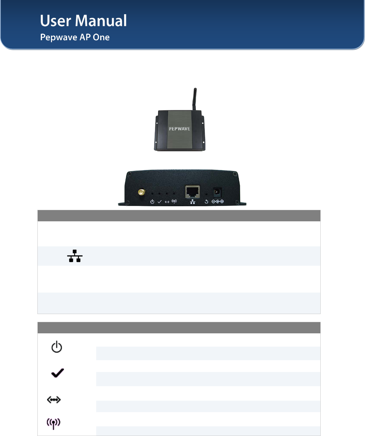
Connectors
Antenna
(Left-most
Connector)
A RP-SMA connector for connecting the antenna.
WAN A 10/100BaseT Ethernet connector, normally to be connected to back haul
network.
Reset
A reset button to be depressed with a pin. Depress and hold for at least 5
seconds to restore factory defaults.
For further details, please refer to Section 10, Restoration of Factory Defaults.
Power Connector A connector for DC 12V power input, to be connected with the supplied power
adaptor.
LED Indicators
Power
OFF – Power off
ON – Power on
Status
OFF – The unit is initializing.
ON – The unit is ready.
Ethernet
OFF – The Ethernet port is not connected.
ON – The Ethernet port is connected.
Wireless OFF – Wireless is not ready.
On – Wireless is ready.
User Manual
http://www.pepwave.com 7 Copyright © 2011
Pepwave
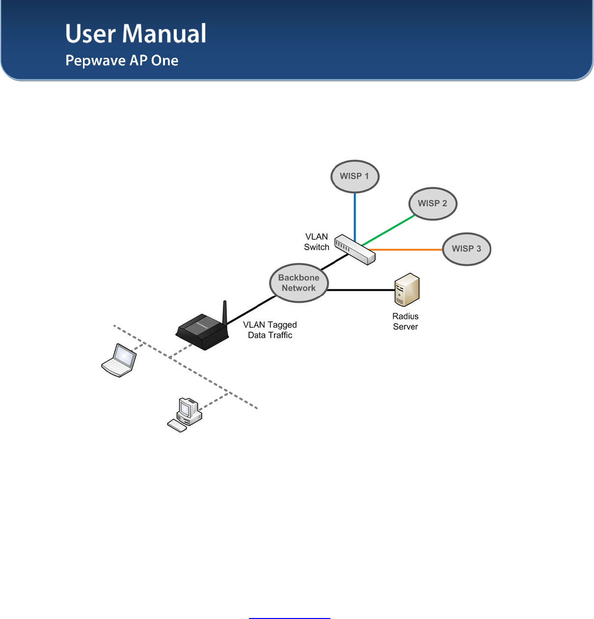
5 Installation
Pepwave AP One acts as a bridge between the wireless and the wired Ethernet interface. A typical setup
is as follows:
5.1 Installation Procedures
1. Attach the antenna to the Pepwave AP One unit.
2. Connect the Ethernet port on the unit with the backbone network using an Ethernet cable. The
port could auto sense the cable is straight-through or cross-over.
3. Connect the power adapter to the power connector of the unit, and then plug in the power adapter.
4. Wait for the status LED to turn green.
5. Connect a PC to the backbone network, and configure the IP address of the PC to be any IP
address between 192.168.0.4 and 192.168.0.254, with subnet mask of 255.255.255.0.
6. With Microsoft Internet Explorer 6 or above, or Mozilla Firefox 2.0 or above, or Google Chrome
2.0 or above, connect to the URL https://192.168.0.3.
7. When asked, enter the default admin login ID and password, admin and public respectively.
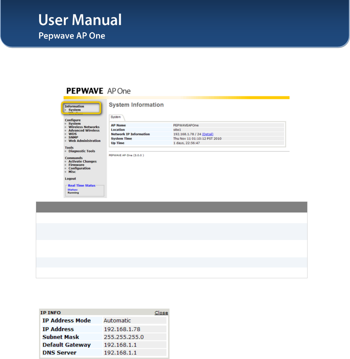
8. After logging in, the following Information main page appears. Please go to Configure > System
to facilitate further configuration of the Pepwave AP One unit.
User Manual
http://www.pepwave.com 8 Copyright © 2011
Pepwave
6 Information
6.1 System
System Information
AP Name This field shows the name of the AP One device defined in the configuration.
Location This field shows the location of the AP One device defined in the
configuration.
Network IP
Information This shows the current gateway IP of the AP One device.
System Time This shows the system time in respect to the time zone selected.
Up Time This shows the up time of the device since it is booted up.
Click on the Detail link next to the Network IP Information to check the following system information:
IP Address Mode, IP Address, Subnet Mask, Default Gateway, DNS Server.
User Manual
http://www.pepwave.com 9 Copyright © 2011
Pepwave
6.2 Wireless
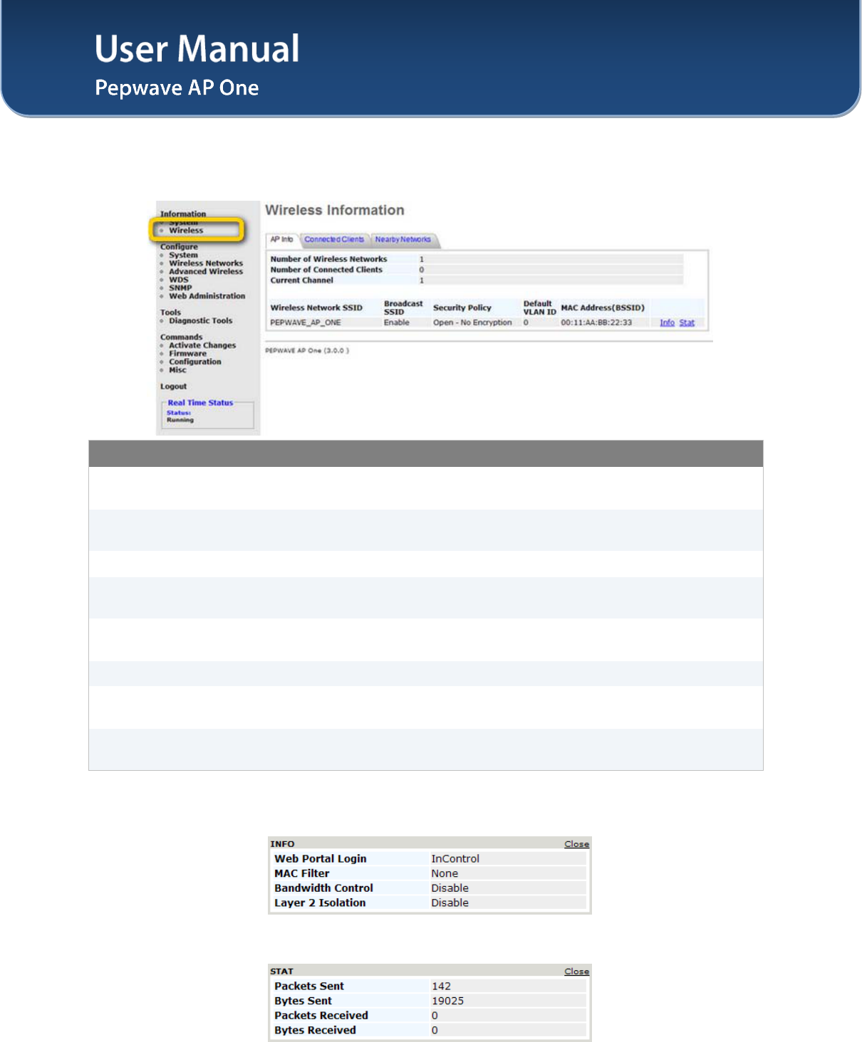
6.2.1 AP Info
Wireless Information – AP Info
Number of Wireless
Networks This indicates the number of wireless networks.
Number of
Connected Clients This indicates the number of associated clients.
Current Channel This shows which 802.11 channel the system is using.
Wireless Network
SSID This shows which SSID the client is associated.
Broadcast SSID This setting shows whether or not the ESSID of this wireless network profile
can be scanned by Wi-Fi clients.
Security Policy This setting shows the wireless authentication and encryption methods.
Default VLAN ID This setting shows the VLAN ID tagged on all outgoing packets generated from
this wireless network profile.
MAC Address
(BSSID) This shows the detailed BSSIDs for that particular wireless network profile.
Click on the Info link to check the following wireless information: Web Portal Login, Wireless Network
Firewall, MAC Filter, Bandwidth Control, Layer 2 Isolation.
Click on the Stat link to check the following networking statistics: Packets Sent, Bytes Sent, Packets
Received, Bytes Received.
User Manual
http://www.pepwave.com 10 Copyright © 2011
Pepwave
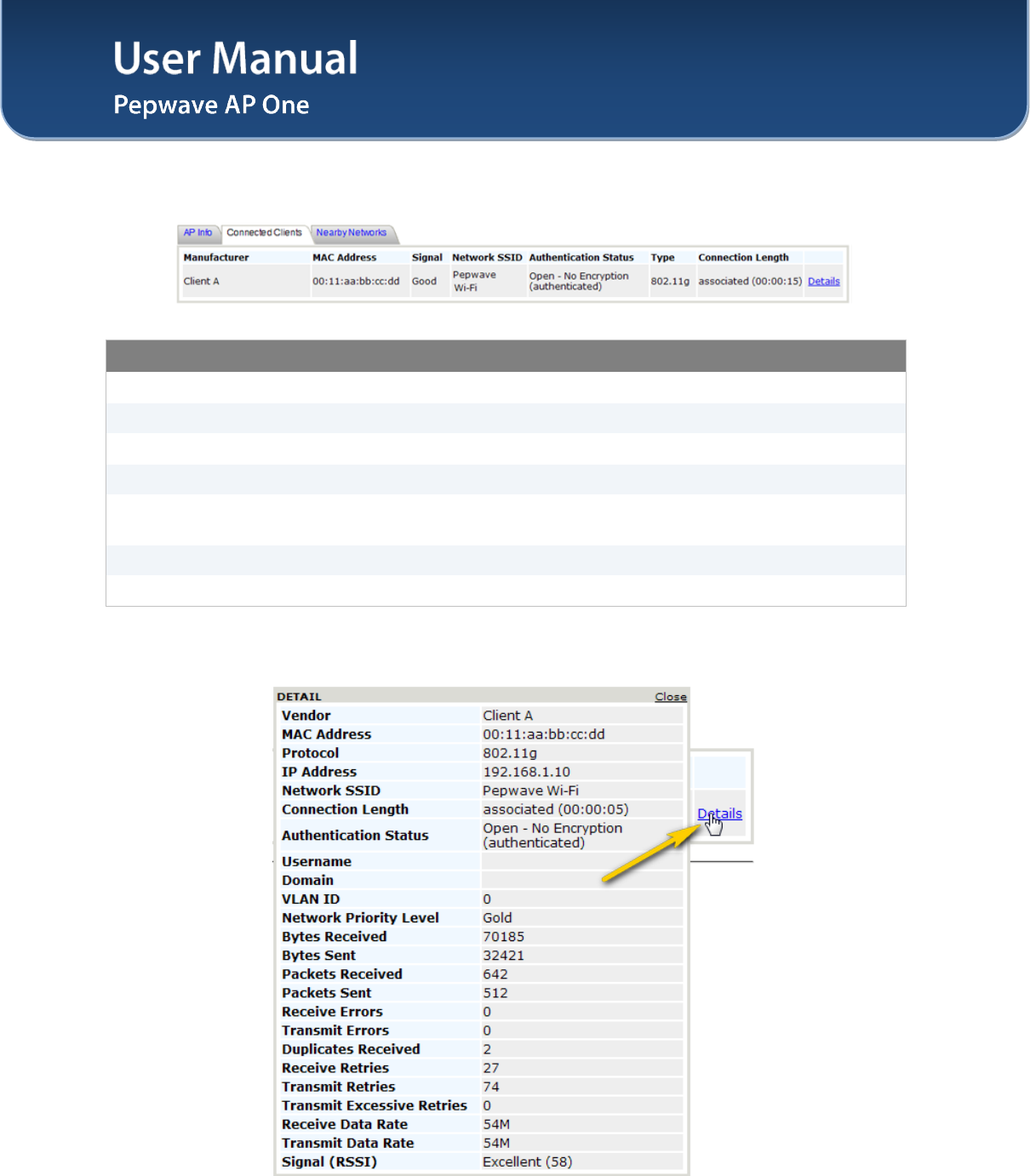
6.2.2 Connected Clients
Wireless Information – Connected Clients
Manufacturer This shows the manufacturer based on the MAC prefix.
MAC address This shows the client MAC address.
Signal This shows the signal strength.
Network SSID This shows which SSID the client is associated.
Authentication
Status This shows the client authentication method(s).
Type This shows the radio mode of the client.
Connection Length This shows the associated duration.
Click on the Details link, more networking statistics will be provided.
User Manual
http://www.pepwave.com 11 Copyright © 2011
Pepwave
Wireless Information – Connected Clients - Details
Vendor This shows the manufacturer based on the MAC prefix.
MAC Address This shows the client MAC address.
Protocol This shows the radio mode of the client.
IP Address This shows the IP address of connected client.
Network SSID This shows which SSID the client is associated.
Connection Length This shows the associated duration.
Authentication
Status This shows the client authentication method(s).
Username This shows the user name of the connected client.
Domain This shows the domain name of the connected client.
VLAN ID This shows the VLAN ID of the connected client.
Network Priority
Level This shows the priority level of internet transfers of this connect client.
Bytes Received This shows the transmitted size this client received from the AP.
Bytes Sent This shows the transmitted size this client sent out to the AP.
Packets Received This shows the packet number this client received from the AP.
Packets Sent This shows the packet number this client sent out to the AP.
Receive Errors This shows the number of errors this client received from the AP.
Transmit Errors This shows the number of errors this client transmitted to the AP.
Duplicates
Received This shows the number of duplicates received by the client from the AP.
Receive Retries This shows the number of retries this client received from the AP.
Transmit Retries This shows the number of retries this client transmitted to the AP.
Transmit Excessive
Retries This shows the number of excessive retries this client transmitted to the AP.
Receive Data Rate This shows the receive data rate of the client from the AP.
Transmit Data Rate This shows the transmit data rate of the client to the AP.
Signal (RSSI) This shows the signal strength received by the client.
User Manual
http://www.pepwave.com 12 Copyright © 2011
Pepwave
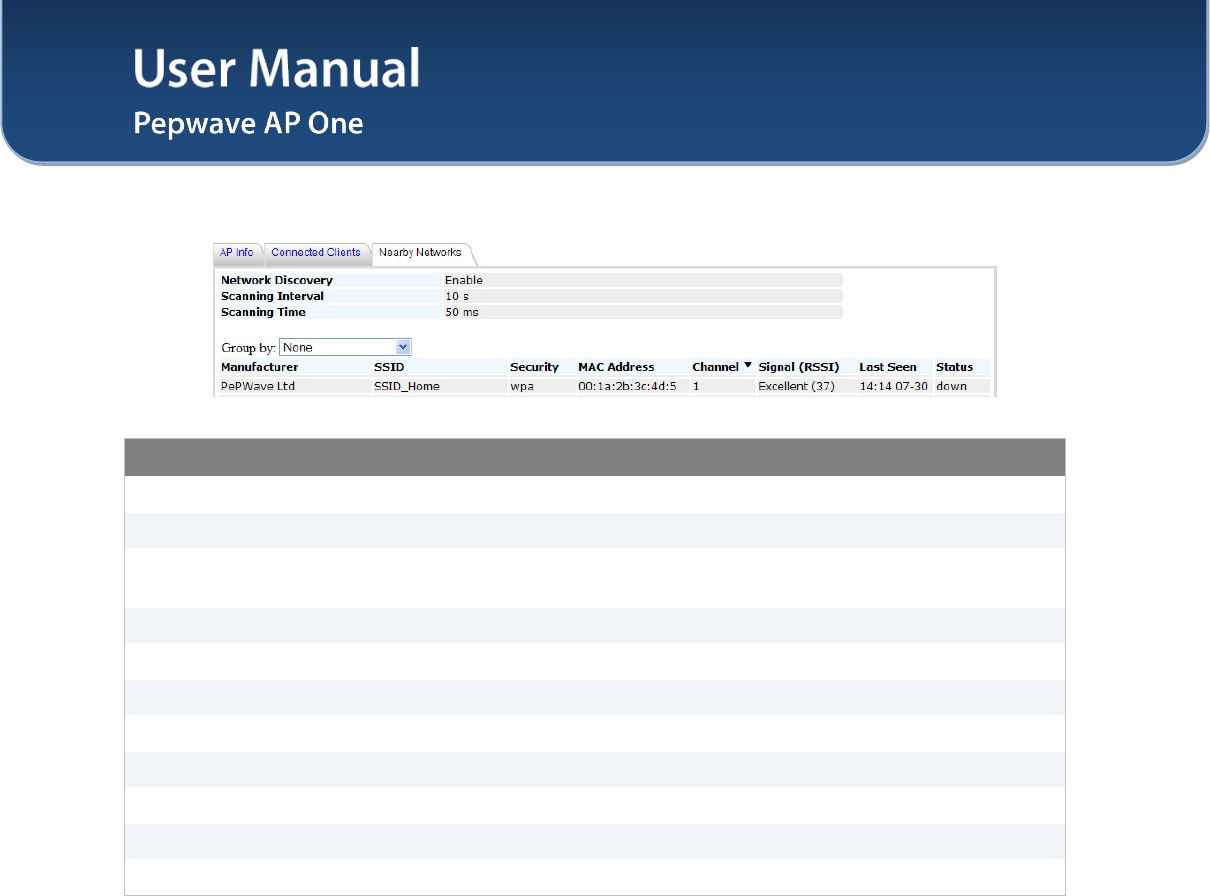
6.2.3 Nearby Networks
Wireless Information – Nearby Networks
Network Discovery This shows if the AP would scan and discover nearby network.
Scanning Interval This shows how often the AP goes to other channels to discover nearby AP.
Scanning Time This shows how long the AP stays on the other channels to discover a nearby
AP.
Manufacturer This shows the manufacturer based on the MAC prefix.
SSID This shows which SSID the client is associated.
Security This shows the client authentication method(s).
MAC address This shows the client MAC address.
Channel This shows the channel of the existing Bssid.
Signal (RSSI) This shows the signal strength.
Last Seen This indicates the time stamp of the access point sc
Status This shows the current status of this nearby network.
User Manual
http://www.pepwave.com 13 Copyright © 2011
Pepwave
7 Configuration
7.1 System
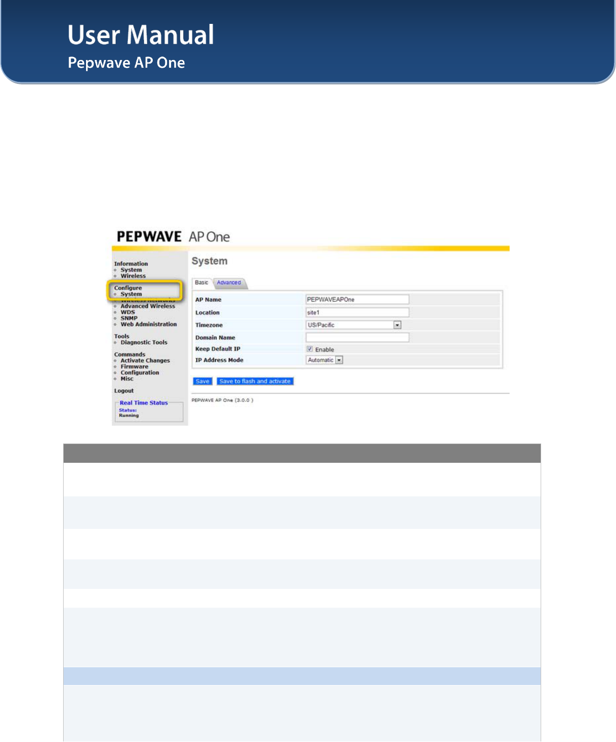
Upon selecting System under Configure section from the navigation bar on the left, the following page
shows the configuration options:
7.1.1 Basic
System Settings - Basic
AP Name A user-specified name for this access point.
This value can be retrieved via SNMP.
Location A user-specified name for the location of the access point.
This value can be retrieved via SNMP.
Timezone This option specifies the time region to be used for representing the time on
the system.
Domain Name Domain name can be set for wireless clients to have a readable name for the
web management.
Keep Default IP With this option disabled, default IP 192.168.0.3 of the device will be disabled.
IP Address Mode
The options are Automatic and Manual.
Automatic: IP address of the Pepwave AP One unit is acquired from a DHCP
server on the Ethernet segment.
Manual: A user-specified IP address is used.
IP Address Mode – Manual
Static IP Address
This specifies the unique IP address for the Pepwave AP One unit to
communicate on the Ethernet segment.
This IP address is distinct from the admin IP address 192.168.0.3 on the
Ethernet segment.
User Manual
http://www.pepwave.com 14 Copyright © 2011
Pepwave
Subnet Mask This setting specifies the subnet mask of the Pepwave AP One unit.
Default Gateway This setting specifies the default gateway of the Pepwave AP One unit.
DNS Server This is the DNS server address to be used by the Pepwave AP One unit for
resolving host names.
IP Address Mode – PPPoE
PPPoE Username
This specifies the username required in order to connect via PPPoE to acquire
Internet connectivity. The information is typically determined by and can be
obtained from the ISP.
PPPoE Password
This specifies the password required in order to connect via PPPoE to acquire
Internet connectivity. The information is typically determined by and can be
obtained from the ISP.
PPPoE Service
Name
This is a PPPoE parameter which is provided by the ISP.
Note: Leave this field empty if you are not sure.
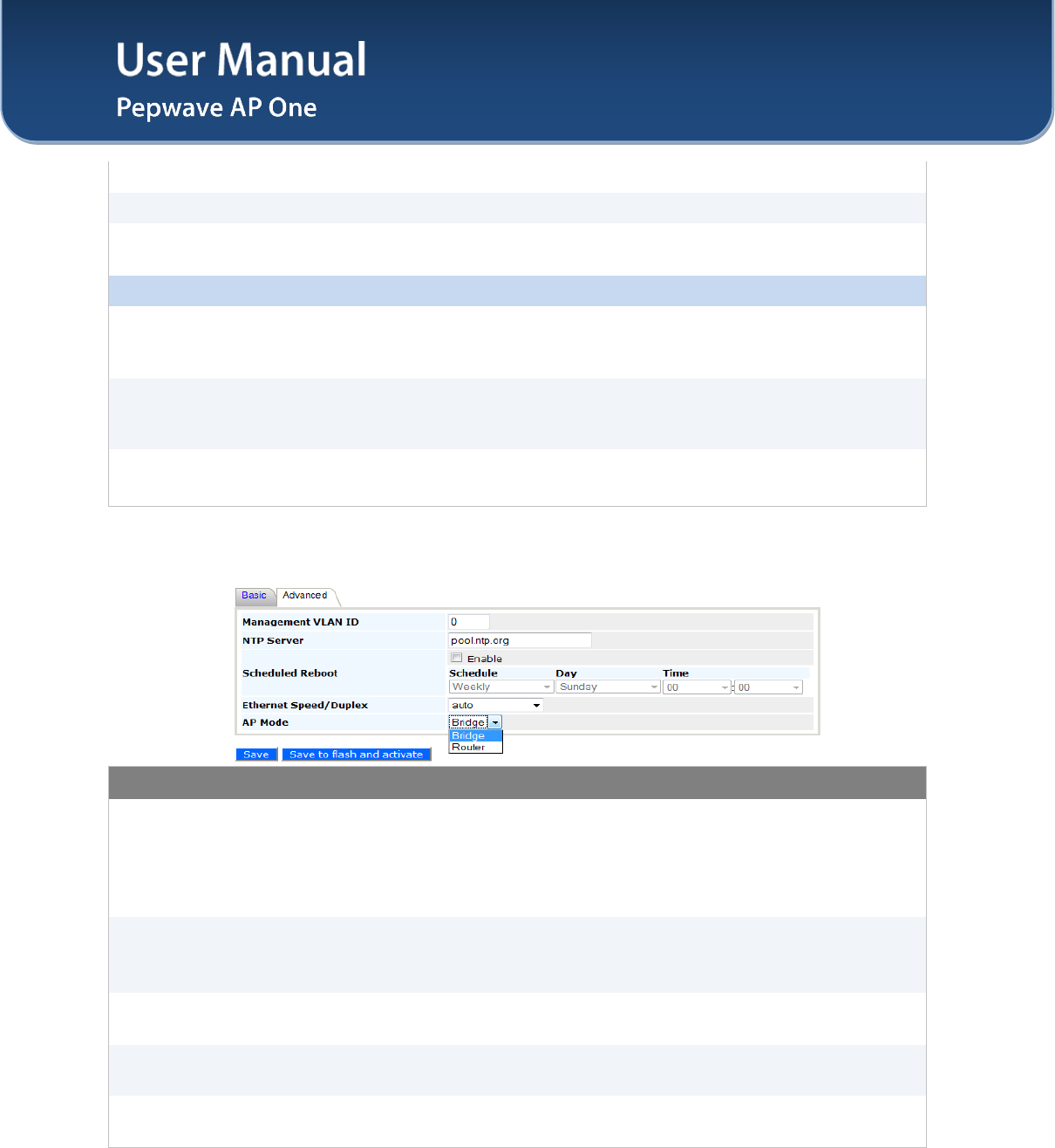
7.1.2 Advanced
System Settings - Advanced
Management VLAN
ID
This specifies the VLAN from which management sessions are allowed. The
establishment of management sessions is restricted only to the specified VLAN
ID. If Management VLAN ID is set to zero, no VLAN restriction is applied.
The default value of this setting is zero. It means no tagging is enabled
(instead of tagged with zero).
NTP Server
This is the Network Time Protocol (NTP) Server hostname to be used for
synchronizing system clock of Pepwave AP One.
The default value of this setting is pool.ntp.org.
Scheduled Reboot The system would perform reboot based on the scheduled time set. Click the
box above the Schedule to Enable this feature.
Ethernet
Speed/Duplex This setting provides the option to set the speed of the Ethernet.
AP Mode Available options are Bridge and Router. With this option set as Router, the
following Manual Router Settings will be available.
User Manual
http://www.pepwave.com 15 Copyright © 2011
Pepwave
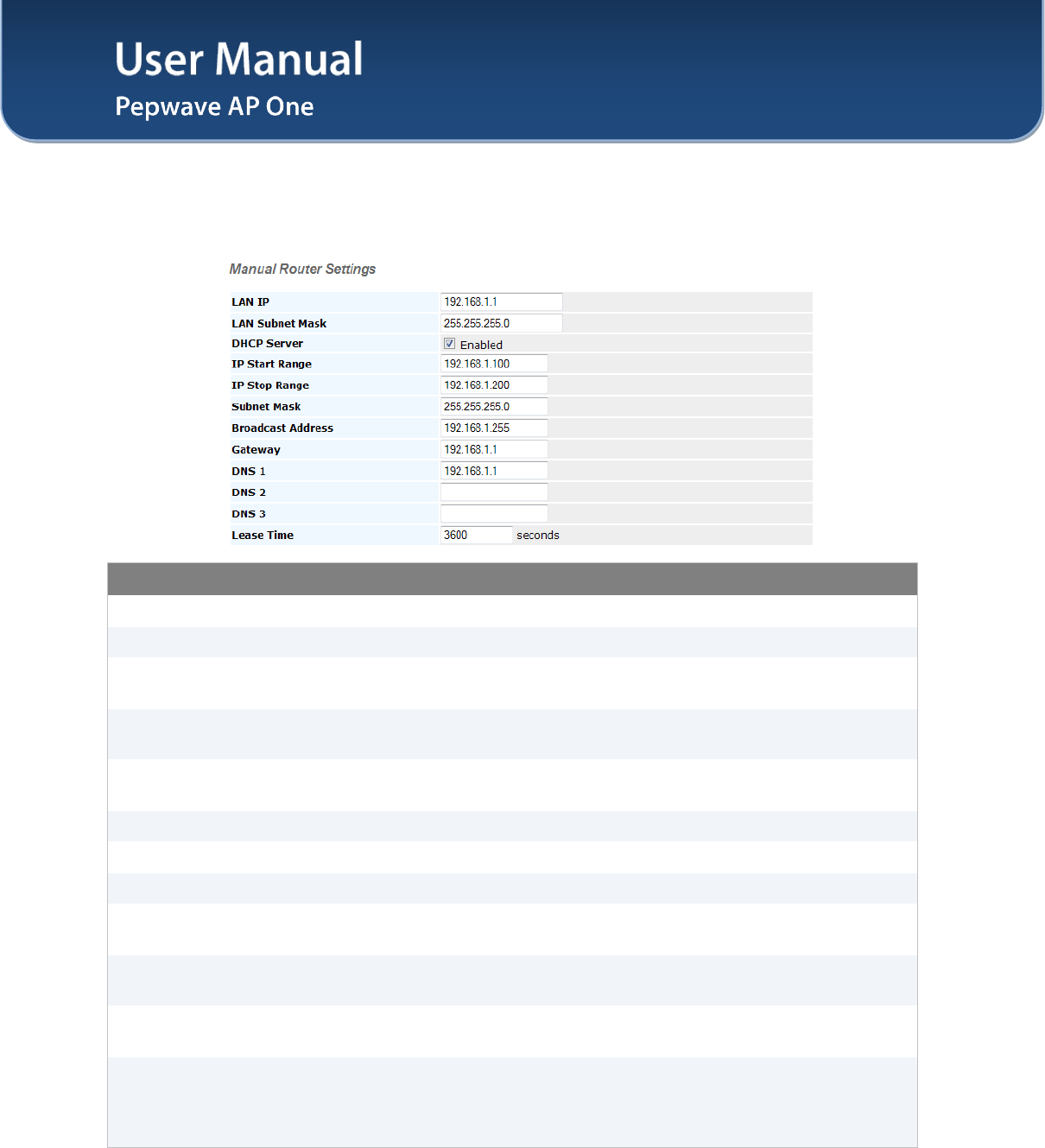
7.1.3 Manual Router Settings
Manual Router Settings will only be available when the AP Mode in the previous section had been
selected as Router mode. You can use the AP One as a DHCP server for other devices behind.
DHCP Server Parameters
LAN IP This setting specifies the DHCP server IP address.
LAN Subnet Mask This setting specifies the subnet mask of the DHCP server.
DHCP Server Checked the box to enable the DHCP Server of this device. Following options
will be enabled once you have checked and enabled the service.
IP Start Range This setting specifies the first address in the range of IP addresses to be
assigned to DHCP clients.
IP Stop Range This setting specifies the last address in the range of IP addresses to be
assigned to DHCP clients.
Subnet Mask This setting specifies the subnet mask to be used by DHCP clients.
Broadcast Address This setting specifies the broadcast address to be used by DHCP clients.
Gateway This setting specifies the default routing gateway to be used by DHCP clients.
DNS 1 This setting specifies the IP address of the primary DNS Server to be offered to
DHCP clients.
DNS 2 This setting specifies the IP address of the secondary DNS Server to be
offered to DHCP clients.
DNS 3 This setting specifies the IP address of the tertiary DNS Server to be offered to
DHCP clients.
Lease Time
This setting specifies the length of time throughout which an IP address of a
DHCP client remains valid. Upon expiration of the Lease Time, the assigned IP
address will no longer be valid and the renewal of the IP address assignment
will be required.
User Manual
http://www.pepwave.com 16 Copyright © 2011
Pepwave
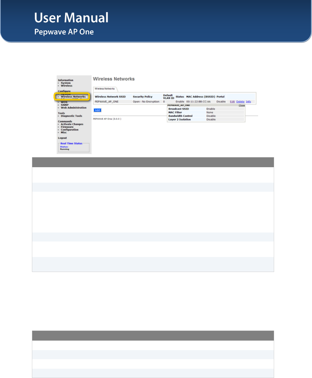
7.2 Wireless Networks
Upon selecting Wireless Networks under Configure section from the navigation bar on the left, the
following shows the configured SSID available on the system:
General Wireless Networks Settings
Wireless Network
SSID The SSID of the virtual Access Point (AP).
Security Policy Shows the configured wireless authentication and encryption methods.
Default VLAN ID
This setting specifies the VLAN ID to be tagged on all outgoing packets
generated from the virtual AP (i.e. packets that travel from the Wi-Fi segment,
through the Pepwave AP One unit to Ethernet segment via the LAN port).
If 802.1x is enabled, a per-user VLAN ID can be specified in the authentication
reply from the Radius server. If it is set, the value specified via Default VLAN
ID will be overridden.
Status Shows whether the virtual AP is enabled or disabled.
MAC Address
(BSSID) Shows the detailed BSSIDs.
Portal Shows if the InControl Guest Portal is enabled. Please refer to section 7.2.2 for
details.
To add a new virtual AP, click the Add button. To modify the settings for a virtual AP, click the link Edit on
the right of the desired WLAN SSID, upon which the following Wireless Network Details is displayed.
Click on the Info link to check the following networking statistics: Broadcast SSID, MAC Filter,
Bandwidth Control, Layer 2 Isolation.
General Wireless Networks Settings – Info
Broadcast SSID This shows if the Broadcast SSID feature of this network is enabled.
MAC Filter This shows if the MAC Filter feature of this network is enabled.
Bandwidth Control This shows if the Bandwidth Control feature of this network is enabled.
Layer 2 Isolation This shows if the Layer 2 Isolation feature of this network is enabled.
User Manual
http://www.pepwave.com 17 Copyright © 2011
Pepwave
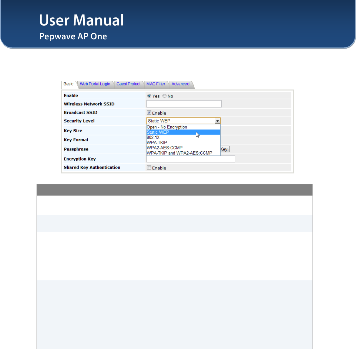
7.2.1 Wireless Network Details - Basic
Wireless Networks Details - Basic
Enable Select Yes to enable the virtual AP, or No to disable the virtual AP.
By default, the virtual AP is enabled.
Wireless Network
SSID This setting specifies the SSID of the virtual AP to be scanned by Wi-Fi clients.
Broadcast SSID
This setting specifies whether or not the ESSID of the virtual AP can be
scanned by Wi-Fi clients.
Note that the BSSID (i.e. the MAC address of the virtual AP) cannot be hidden
from the scan. To associate with the virtual AP, clients must specify the correct
ESSID upon association.
Broadcast SSID is enabled by default.
Security Level
This setting configures the wireless authentication and encryption methods.
Available options are: Open - No Encryption, Static WEP, 802.1X, WPA-
TKIP and WPA2-AES:CCMP.
Selecting Open - No Encryption disables encryption.
For details on the other options, please refer to:
7.2.1.1 - Static WEP Parameters
7.2.1.2 - 802.1x Parameters
7.2.1.3 - WPA Parameters
User Manual
http://www.pepwave.com 18 Copyright © 2011
Pepwave
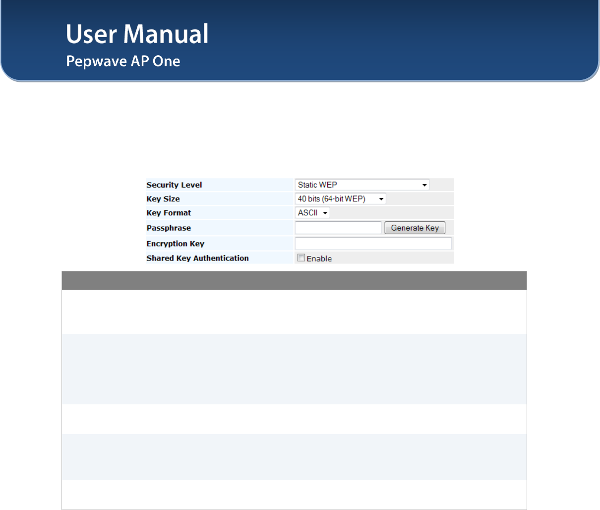
7.2.1.1 Static WEP
The configuration of Static WEP parameters enables pre-shared WEP key encryption. Authentication is
not supported by this method.
The security level of this method is known to be weak.
Static WEP parameters are entered via the following screen upon selection:
Static WEP Parameters
Key Size
The setting can be configured as either 40 bits (64-bit WEP) or 104 bits (128-
bit WEP).
(For WDS setting, 128 bits will also be available.)
Key Format
The setting can be configured as either ASCII or HEX.
• ASCII will be applied to encryption keys that are manually entered
only.
• HEX will be applied to encryption keys that are either manually entered
or automatically generated.
Passphrase Combination of words and characters used to generate an encryption key.
Click Generate Key to create the key.
Encryption Key
This setting specifies a user-specified encryption key value.
For ASCII format, key length is either 5 or 13.
For HEX format, key length is either 10 or 26.
Shared Key
Authentication
This setting enables the use of shared key authentication. Open authentication
is the default authentication.
User Manual
http://www.pepwave.com 19 Copyright © 2011
Pepwave
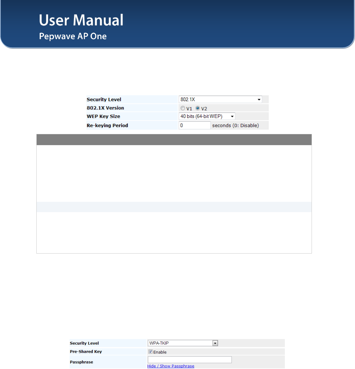
7.2.1.2 802.1X Parameters
The configuration of 802.1X parameters enables Radius-based 802.1X authentication with a dynamic
WEP key. Once selected, Radius Server Setting will be available.
The configuration screen is as follows:
802.1x Parameters
802.1X Version
This setting selects between v1 or v2 of the 802.1x EAPOL.
When v1 is selected, both v1 and v2 clients can associate with the access
point. However, when v2 is selected, only v2 clients can associate with the
access point.
Most modern wireless clients support v2. In the event that there are stations
that do not support v2, select the option v1.
By default, the value of the setting is v2.
WEP Key Size The setting can be configured as either 40 bits or 104 bits.
Re-keying Period
This setting specifies the length of time throughout which the broadcast key
remains valid. Upon expiration of Re-keying Period, the broadcast key will no
longer be valid and the renewal of the broadcast key will be required.
The default is 14400 seconds (i.e. 4 hours).
A value of 0 disables re-keying.
7.2.1.3 WPA parameters
The configuration of WPA parameters enables WPA-TKIP, WPA2-AES:CCMP and WPA-TKIP and
WPA2-AES:CCMP.
To enable WPA and WPA-PSK, configure WPA-TKIP. To enable WPA2 and WPA2-PSK, configure
WPA2-AES.
When WPA or WPA2 is configured, Radius-based 802.1x authentication with TKIP encryption method is
enabled. Under this configuration, the Pre-Shared Key option should be disabled.
The security level of this method is known to be very high.
When WPA-PSK or WPA2-PSK is configured, a Pre-Shared Key, or Passphrase, is used for data
encryption and authentication. Under this configuration, the Pre-Shared Key option should be enabled.
Key length must be between 8 and 63 characters (inclusive).
The security level of this method is known to be high.
User Manual
http://www.pepwave.com 20 Copyright © 2011
Pepwave
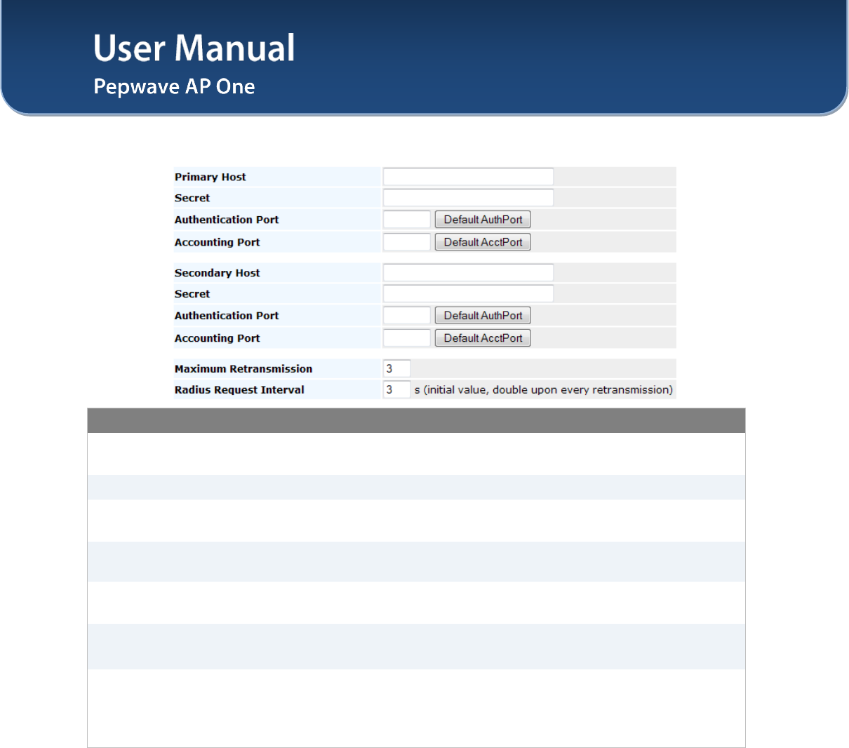
7.2.1.4 Radius Server Settings
Radius Server Settings
Primary Host When 802.1x authentication is configured, the Radius server specified by this
setting will be used for authentication and accounting.
Secret This is the secret for accessing the Radius server.
Authentication Port This specifies the UDP port number for the Authentication port of the Radius
server.
Accounting Port This specifies the UDP port number for the Accounting port of the Radius
server.
Secondary Host This setting specifies the Radius server to used
for authentication and
accounting in the event that the host specified by Primary Host is unavailable.
Maximum
Retransmission
This specifies the maximum number of retry for RADIUS authentication.
By default, it is set as 3.
Radius Request
Interval
This specifies the time interval in second between each RADISU request
attempt. Note that the request time interval would be doubled every
retransmission.
By default, it is set as 3s.
User Manual
http://www.pepwave.com 21 Copyright © 2011
Pepwave
7.2.2 Web Portal Login
Simply registering the devices with Pepwave InControl, users can apply configurations, firmware, and
monitor network activity remotely through this centralized management system. For more details, you can
refer to Pepwave website at: http://www.pepwave.com/products/incontrol/.
Tip: How to Set Up AP One Guest Portal in InControl
To set up Guest Portal, you need to (1) enable guest portal function and (2) create guest accounts and
set up portal page.
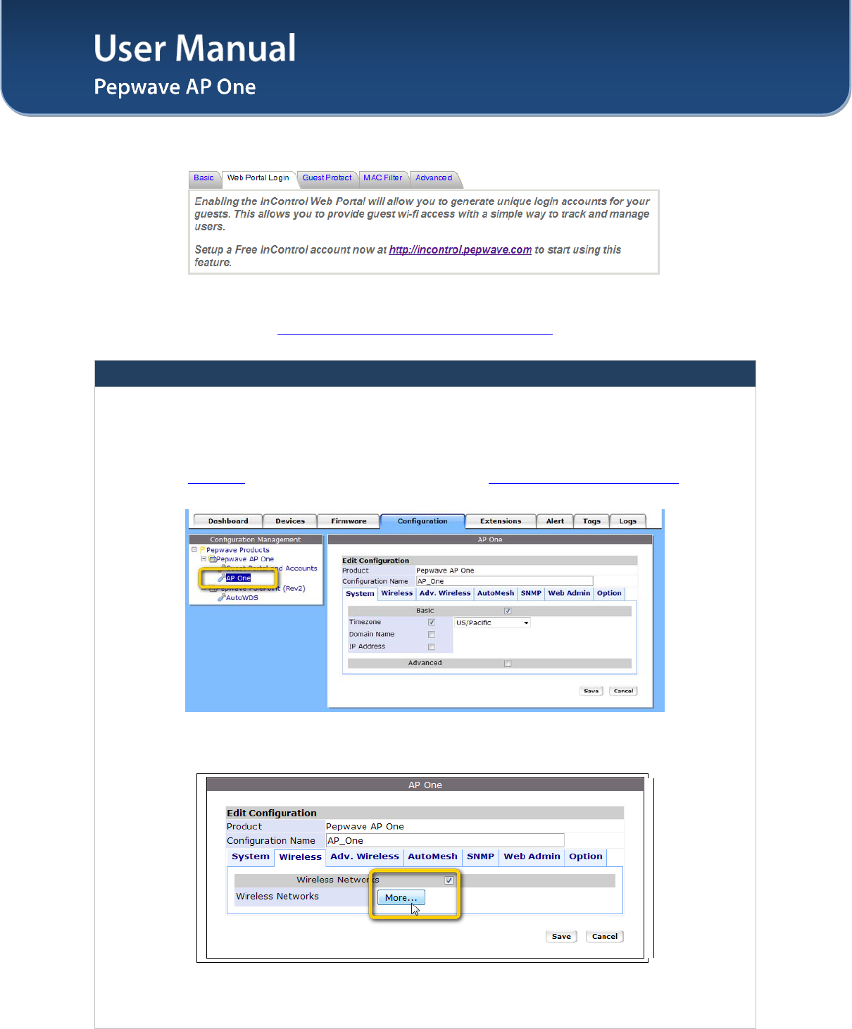
Step One: Enable Guest Portal
1. Log in InControl using your username and password. <https://incontrol.pepwave.com/>
2. Click "Configuration" tab and find the desired configuration profile.
3. To find your wireless network, click "Wireless" tab, check the box next to "Wireless Networks"
and click "More..." button.
4. Click on the name of the SSID you have set up.
User Manual
http://www.pepwave.com 22 Copyright © 2011
Pepwave
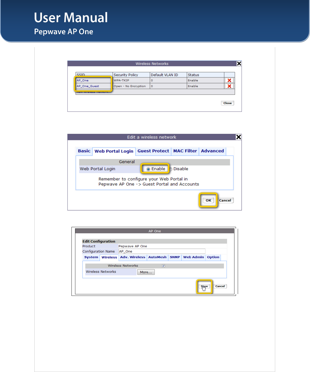
(Note: If you have not added a wireless network, you can click "New wireless network..." to set
up a new one.)
5. On the "Edit a wireless network" screen, click "Web Portal Login" tab. Click "Enable" to enable
the Web Portal Login function. Click "OK" to continue.
6. Click "Save" button to save the changes.
User Manual
http://www.pepwave.com 23 Copyright © 2011
Pepwave
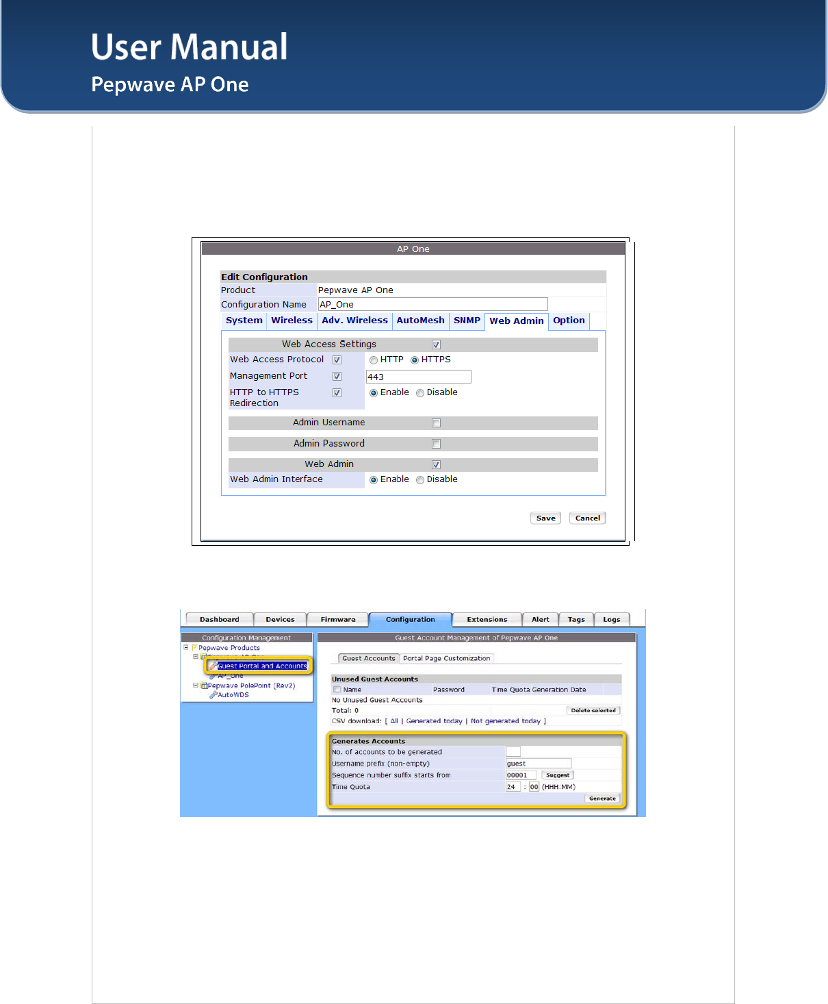
7.
Click the "Web Admin" tag, and setup the web access as follows:
Web Access Protocol: HTTPS
Management Port: 443
HTTP to HTTPS Redirection: Enable
Click Save button to save the settings.
Step Two: Create Guest Accounts and Set Up Portal Page
8. Go to "Guest Portal and Accounts" by clicking on the link at the left panel.
9. You can generate more than one account at one time. Change the parameters in the fields No.
of accounts to be generated, Username prefix, Sequence number suffix and Time Quota. Default time
limit is set to 24 hours. You can change the time limit.
10. Click "Generate" button.
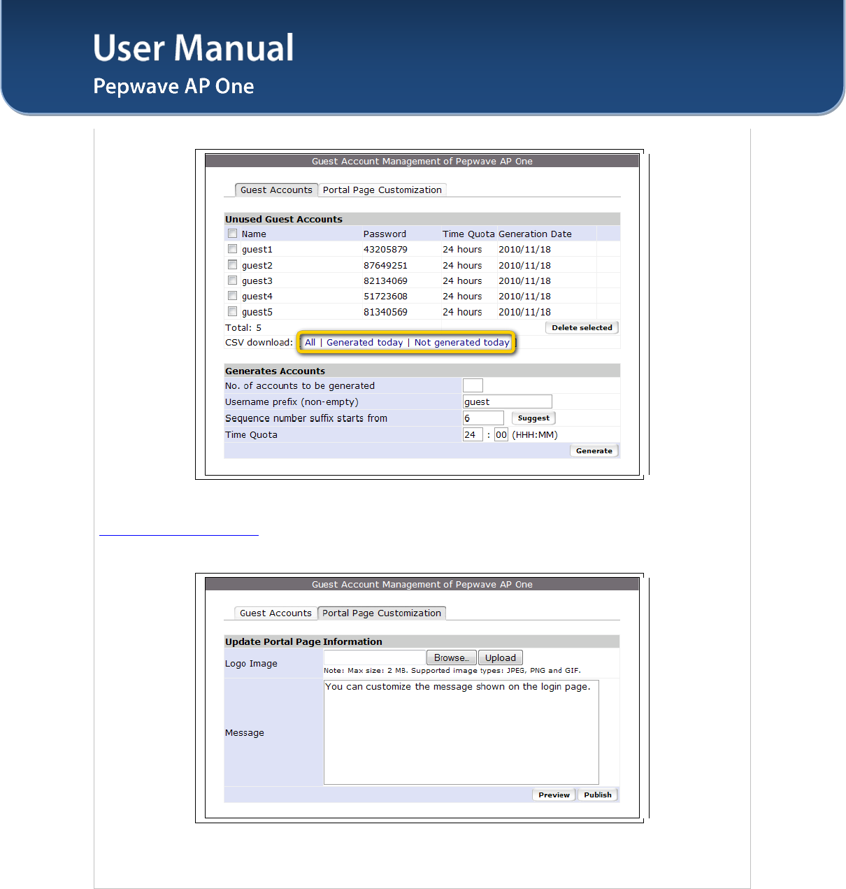
11. You should now have some guest accounts generated as shown in the table "Unused Guest
Accounts". You can download the accounts information in CSV file by clicking the "All", "Generated
User Manual
http://www.pepwave.com 24 Copyright © 2011
Pepwave
today" or "Not generated today" links.
12. A standard portal page will be generated automatically after guest accounts are generated
(http://guest.pepwave.com). You can customize the portal page by clicking on the "Portal Page
Customization" tab. In the screen upload your logo image and enter message for guests. You can
preview your portal page and then publish the portal page.
Your guest accounts and portal page are now ready for use.
User Manual
http://www.pepwave.com 25 Copyright © 2011
Pepwave
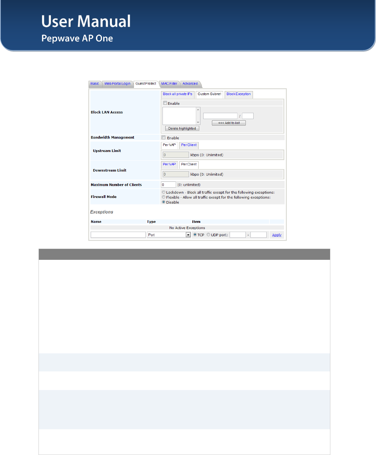
7.2.3 Guest Protect
Wireless Networks Details - Guest Protect
Block LAN
Access
This option enables the settings to Block all private IPs / Custom Subnet /
Block Exception.
If you have selected Block all private IPs or Custom Subnet, these IPs /
Subnets will be blocked no matter what "Firewall Mode" selected. When Block
Exception is selected, IPs entered will be excluded from the blocking list.
1. Private IP -- This includes the commonly known private IPs:
• 192.168.0.0 - 192.168.255.255
• 172.16.0.0 - 172.31.255.255
• 10.0.0.0 - 10.255.255.255
2. Custom Subnet -- This includes user specified IP subnets to be blocked.
3. Block Exception – Only IPs specified will NOT be blocked.
Bandwidth
Management
This option enables the settings to control upstream and downstream limits. You
can select to either control the bandwidth usage Per VAP or Per Client.
Maximum Number
of Clients
This setting specifies the maximum number of clients that can be connected to
the AP One simultaneously. By default, it is set to 0: unlimited.
Firewall Mode
This setting specifies three options: Lockdown, Flexible, and Disable.
• Lockdown – Block all traffic except for the pre-defined exceptions;
• Flexible – Allow all traffic except for the pre-defined exceptions;
• Disable – Firewall mode is disabled. (Default option)
Exceptions
This setting specifies the exceptions when Lockdown or Flexible Firewall Mode
is selected. Exceptions can be added by types, including Port, Domain, IP
Address, MAC Address, Application/Service.
User Manual
http://www.pepwave.com 26 Copyright © 2011
Pepwave
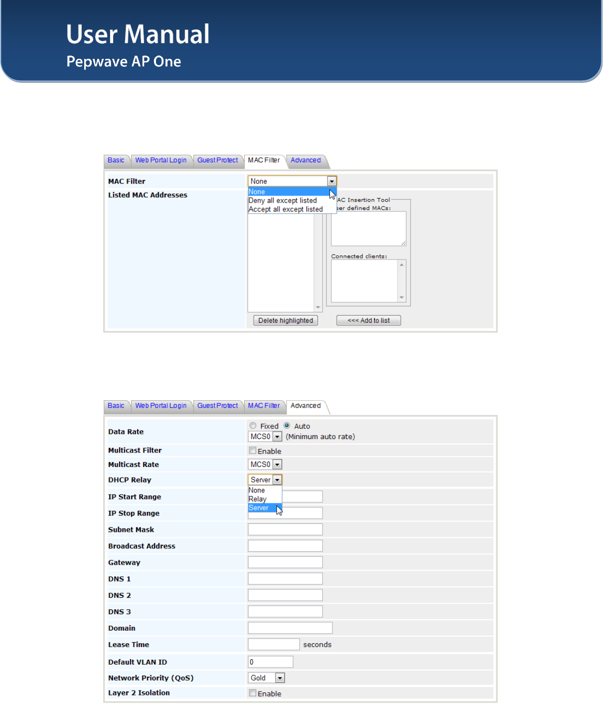
7.2.4 MAC Filter
The settings allow administrator to control the access through Mac address filtering.
Available options are: None, Deny all except listed, Accept all except listed.
7.2.5 Advanced
User Manual
http://www.pepwave.com 27 Copyright © 2011
Pepwave
Wireless Networks Details -Advanced
Data Rate
There are two options on data rate: Fixed, Auto
Fixed will forced all data packets to be transmitted into the selected transmit
rate. Auto will automatically select the best transmit rate with a condition to
use the selected transmit rate as the minimum auto transmit rate.
The rate options and values will be affected by selected Protocol and Channel
Bonding in section 7.3.1.
Multicast Filter This setting enables the filtering of multicast network traffic to the wireless
SSID.
Multicast Rate
This setting specifies the transmit rate to used for sending multicast network
traffic.
The rate options and values will be affected by selected Protocol and Channel
Bonding in section 7.3.1.
DHCP Relay
The AP One will forward DHCP requests to a specified DHCP Server. This
option prevents broadcast messages from being propagated on the Ethernet
segment. Upon selecting this option, the DHCP Server IP address (or DHCP
Server settings) will be prompted.
Default VLAN ID
This setting specifies the VLAN ID to be tagged on all outgoing packets
generated from the virtual AP (i.e. packets that travel from the Wi-Fi segment,
through the Pepwave AP One unit to Ethernet segment via the LAN port).
If 802.1x is enabled and a per-user VLAN ID is specified in the authentication
reply from the Radius server, then the value specified via Default VLAN ID will
be overridden.
The default value of this setting is 0. That means VLAN tagging is disabled
(instead of tagged with zero).
Network Priority
(QoS)
The 802.1p QoS value to be marked on all outgoing packets generated from
the virtual AP (i.e. packets that travel from the Wi-Fi segment, through the
Pepwave AP One unit to Ethernet segment via the LAN port).
Possible values are Gold, Silver and Bronze.
Layer 2 Isolation
Layer 2 is in reference to the second layer in the ISO Open System
Interconnect model.
When this option is enabled, clients on the same VLAN, SSID or subnet are not
allowed to communicate directly via the Layer 2 Protocol(s). Traffic is passed
to upper communication layer(s).
With this option disabl
ed, clients on the same VLAN are allowed to
communicate with each other directly. (Windows network resources browsing
will be possible.)
By default, the setting is disabled.

User Manual
http://www.pepwave.com 28 Copyright © 2011
Pepwave
7.3 Advanced Wireless Settings
Advanced Wireless Settings provides more options to fine tune the parameters on the system to achieve
the optimal performance.
7.3.1 Radio Settings
Radio Settings
Protocol
Four options are available:
802.11bgn: Pepwave AP One accepts 802.11b, 802.11g and 802.11n client
association requests.
802.11b/g: Pepwave AP One accepts both 802.11b and 802.11g client
association requests.
802.11b Only: Pepwave AP One accepts only 802.11b client association
requests.
802.11g Only: Pepwave AP One accepts only 802.11g client association
requests.
Operating Country
This setting specifies the country / region regulations which Pepwave AP One
unit should follow.
If North America region is selected, RF channels 1 to 11 are available.
Maximum transmission power is 26 dBm (400 mW).
If Europe region is selected, RF channels 1 to 13 are available. Maximum
transmission power is 20 dBm (100 mW).
Note: Above country selection in for non-US model only. Per US FCC rule, country
section has been removed from all us models and only US channel can be selected
from the device.
Channel
This option selects the 802.11 channel to be utilized. Available options are
from 1 to 11, and from 1 to 13 for the country setting of North America region
and Europe region, respectively. (Channel 14 is only available when the
country is selected as Japan with protocol 802.11b.)
If Auto is set, the system would perform channel scanning based on the
scheduled time set and choose the most suitable channel automatically.
Output Power This option enables the configuration of transmission power.
Available options are Max, High, Medium, and Low.
7.3.2 Advanced Features
Advanced Wireless Settings – Advanced Features
Discover Nearby
Network The AP would scan and discover nearby network if this option is enabled.
Scanning Interval This setting determines how often the access point goes to other channels to
discover Neighbor AP.
Scanning Time This setting determines how long the access point stays on the other channels
to discover Neighbor AP.
WMM This option enables the Wi-Fi Multimedia (WMM), as known as Wireless
Multimedia Extensions (WME) on the access point. It is always on by default.
User Manual
http://www.pepwave.com 29 Copyright © 2011
Pepwave
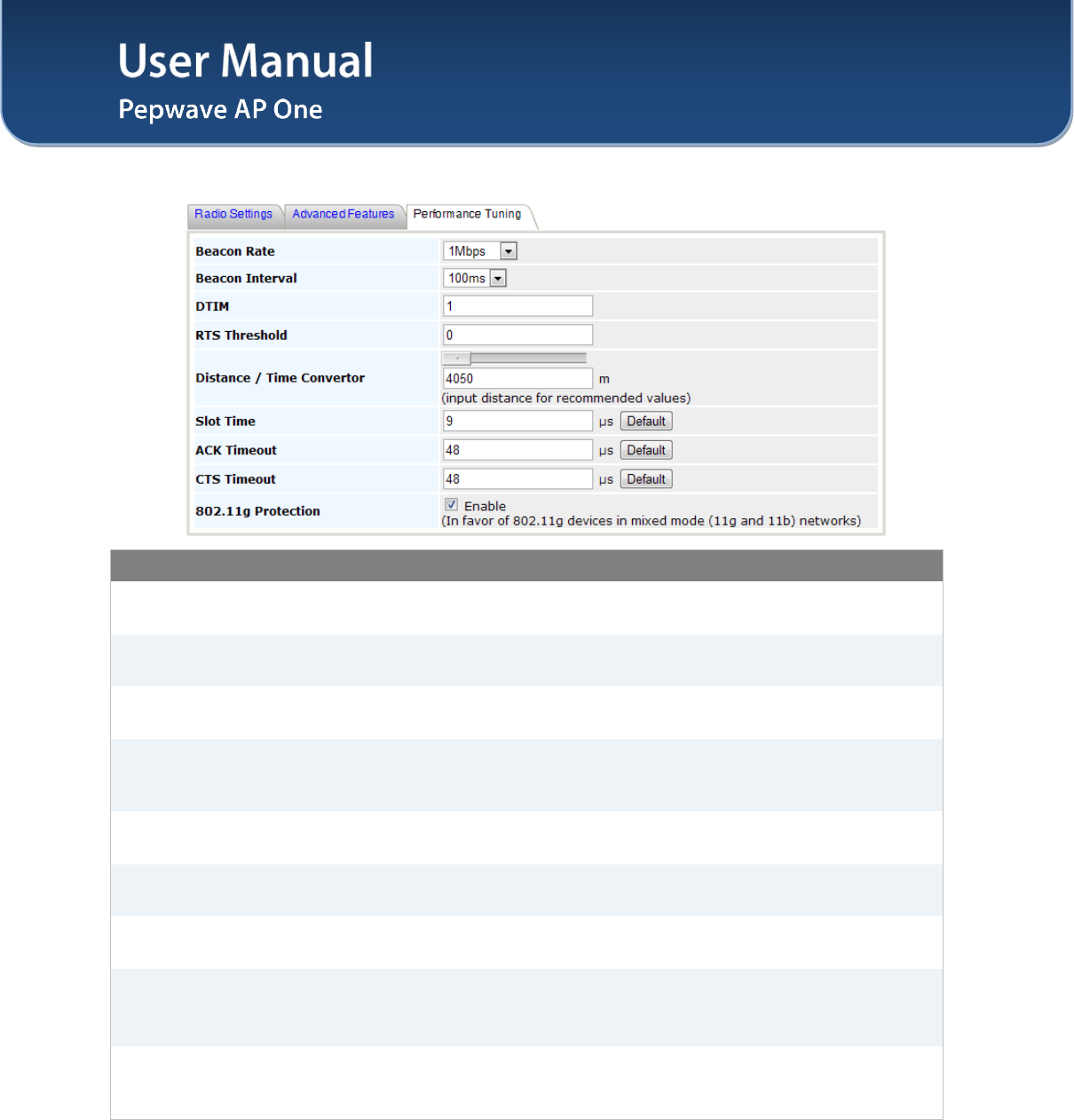
7.3.3 Performance Tuning
Advanced Wireless Settings – Performance Tuning
Beacon Rate This setting provides the option to send beacon in different transmit bit rate and
the bit rates are: 1Mbps, 2Mbps, 5.5Mbps, 6Mbps, 11Mbps.
Beacon Interval This setting provides the option to set the time between each beacon send.
Available options are: 100ms, 250ms and 500ms.
DTIM Period This setting provides the option to set the frequency for beacon to include
Delivery Traffic Indication Message, DTIM. The interval unit is in millisecond.
RTS Threshold
This setting provides the option to set the minimum packet size for the unit to
send an RTS using the RTS/CTS handshake. Setting zero would disable this
feature.
Distance / Time
Convertor
This is a convertor which will automatically adjust and recommend the Slot Time,
ACK Timeout and CTS Timeout based on the distance you have entered.
Slot Time This setting provides the option to modify the unit wait time before it transmits.
The default value is 9μs.
ACK Timeout This setting provides the option to set the wait time to receive acknowledgement
packet before doing retransmission. The default value is 48μs.
CTS Timeout
This setting provides the option to specify the timeout for the unit to wait for CTS
response in the RTS/CTS handshake. The default value is 48μs.
This option will be disabled if you have chosen to use protocol 802.11bgn.
802.11g
Protection
Enable this setting to in favor of 802.11g devices in mixed mode (11g and 11b)
networks. This option will be disabled if you have chosen to use protocol
802.11bgn.
User Manual
http://www.pepwave.com 30 Copyright © 2011
Pepwave
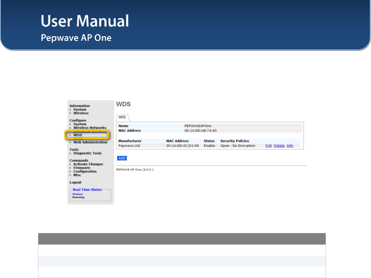
7.4 WDS
Wireless Distributed System - WDS provides a way to link APs together when wired cabling is not
preferable. This also extends the wireless coverage of the wireless network for the wireless clients.
Click Add to add and configure a new WDS peer connection.
WDS Settings
Enable This option enables this entry.
MAC Address This setting gives the MAC address of the other AP to form a WDS link.
Security Policy For more details, please refer to section 7.2.1.1 Static WEP
User Manual
http://www.pepwave.com 31 Copyright © 2011
Pepwave
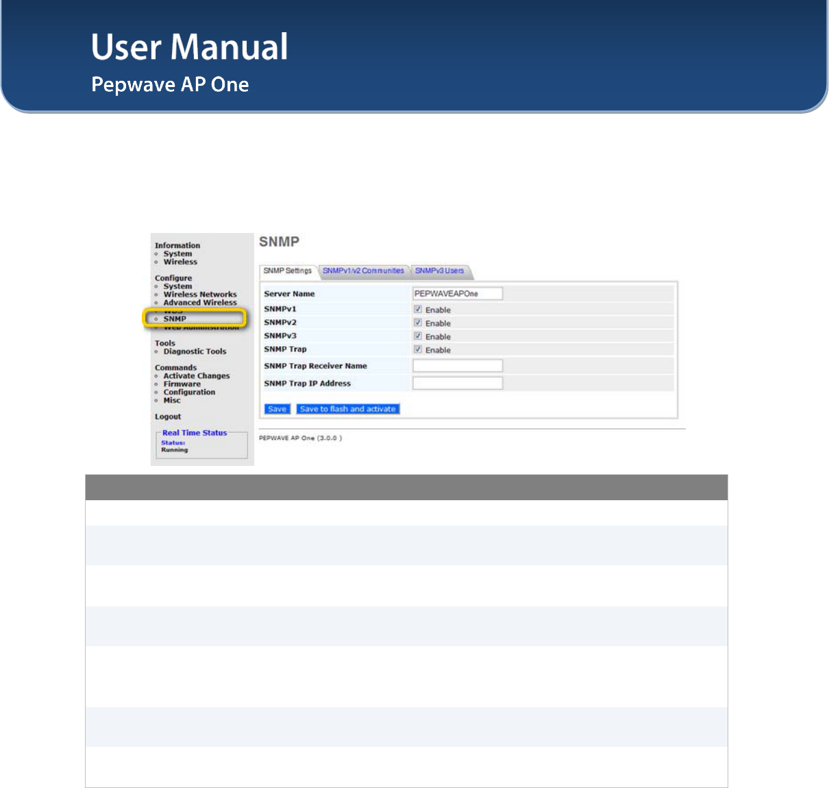
7.5 SNMP
7.5.1 SNMP Settings
Upon selecting SNMP from the navigation bar on the left-hand-side of the Main Menu, the following page
is displayed to enable the configuration of SNMP server settings:
SNMP Settings
Server Name This setting specifies the name that identifies the SNMP server.
SNMPv1 This setting specifies whether to enable or disable the support for Version 1 of
SNMP.
SNMPv2 This setting specifies whether to enable or disable the support for Version 2 of
SNMP.
SNMPv3 This setting specifies whether to enable or disable the support for Version 3 of
SNMP.
SNMP Trap
SNMP Trap is a message initiated from a client and sent to the AP One device.
Once this option is enabled, the following two options for SNMP Trap will be
available for configuration.
SNMP Trap
Receiver Name This setting specifies the name that identifies the SNMP Trap Receiver.
SNMP Trap
IP Address This setting specifies the IP address of the SNMP Trap Receiver.
User Manual
http://www.pepwave.com 32 Copyright © 2011
Pepwave
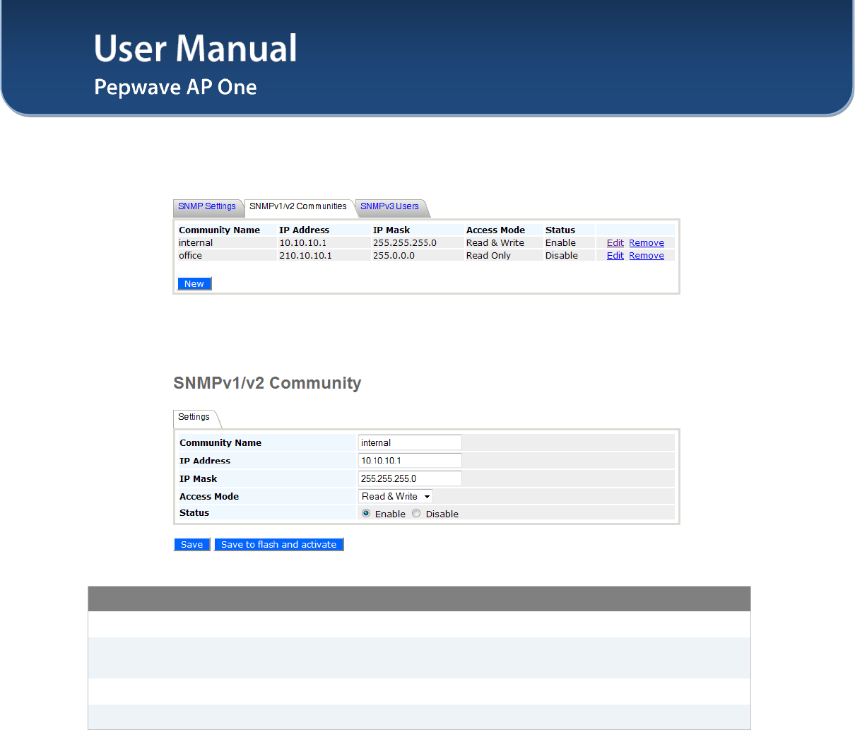
7.5.2 SNMPv1 / SNMPv2 Communities
By adding SNMPv1/v2 Communities, access rights can be controlled. Click on the New button to add one.
SNMPv1 / SNMPv2 Communities
Community Name The password for getting or setting SNMP values.
IP Address and IP
Mask The allowed IP and subnet address which can access the SNMP server.
Access Mode Choose either Read Only or Read & Write.
Status Enable or Disable this community.
User Manual
http://www.pepwave.com 33 Copyright © 2011
Pepwave
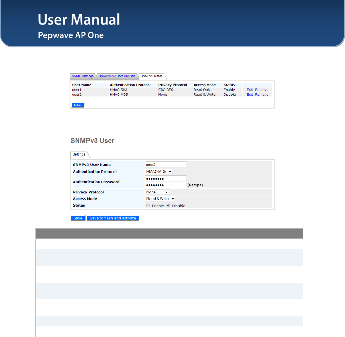
7.5.3 SNMPv3 Users
By adding SNMPv3 users, access rights can be controlled. Click on the New button to add
one.
SNMPv3 User Setting
SNMPv3 User Name The user ID to be allowed to access the SNMP agent.
Authentication
Protocol
The protocol for authenticating the user. Available options are: HMAC-MD5
and HMAC-SHA.
Authentication
Password
Users provided with a correct password will be granted the right to access the
SNMP agent.
Privacy Protocol The encryption method to be used in SNMPv3 communication. Available
options are: None and CBC-DES.
Privacy Password This option is shown only if CBC-DES is chosen as the Privacy Protocol. This
is the key for decrypting the encrypted data.
Access Mode Grant Read or Read & Write access to this user.
Status Enable or Disable this user.
User Manual
http://www.pepwave.com 34 Copyright © 2011
Pepwave
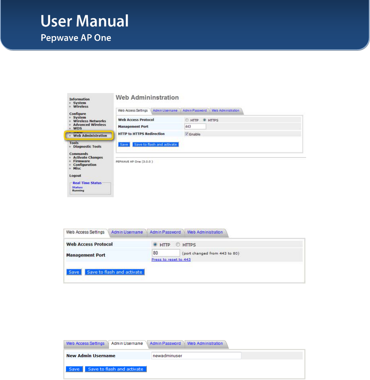
7.6 Web Administration
Upon selecting Web Administration from the navigation bar on the left-hand-side of the Main Menu, the
tabs of configuring the management interface are displayed.
7.6.1 Web Access Settings
The selection Web Access Settings configures the protocol and TCP port number of the web server.
If HTTPS is enabled, HTTP to HTTPS Redirection option will be provided.
7.6.2 Admin Username
The selection Admin Username configures the administrator username for entering Web Admin Interface.
To change to the Username, enter the new username into the Username input fields.
User Manual
http://www.pepwave.com 35 Copyright © 2011
Pepwave
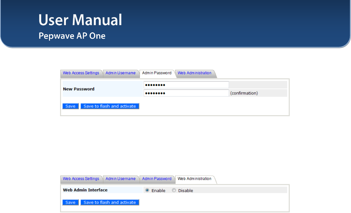
7.6.3 Admin Password
The selection Admin Password configures the administrator password for entering Web Admin Interface.
To change to the password, enter the same new password into the New Password and New Password
(Retype) input fields.
7.6.4 Web Administration
The selection Disable Web Administration turns off the access to Web Administration Interface.
After being turned off, Web Administration Interface can be re-enabled using SNMP.
User Manual
http://www.pepwave.com 36 Copyright © 2011
Pepwave
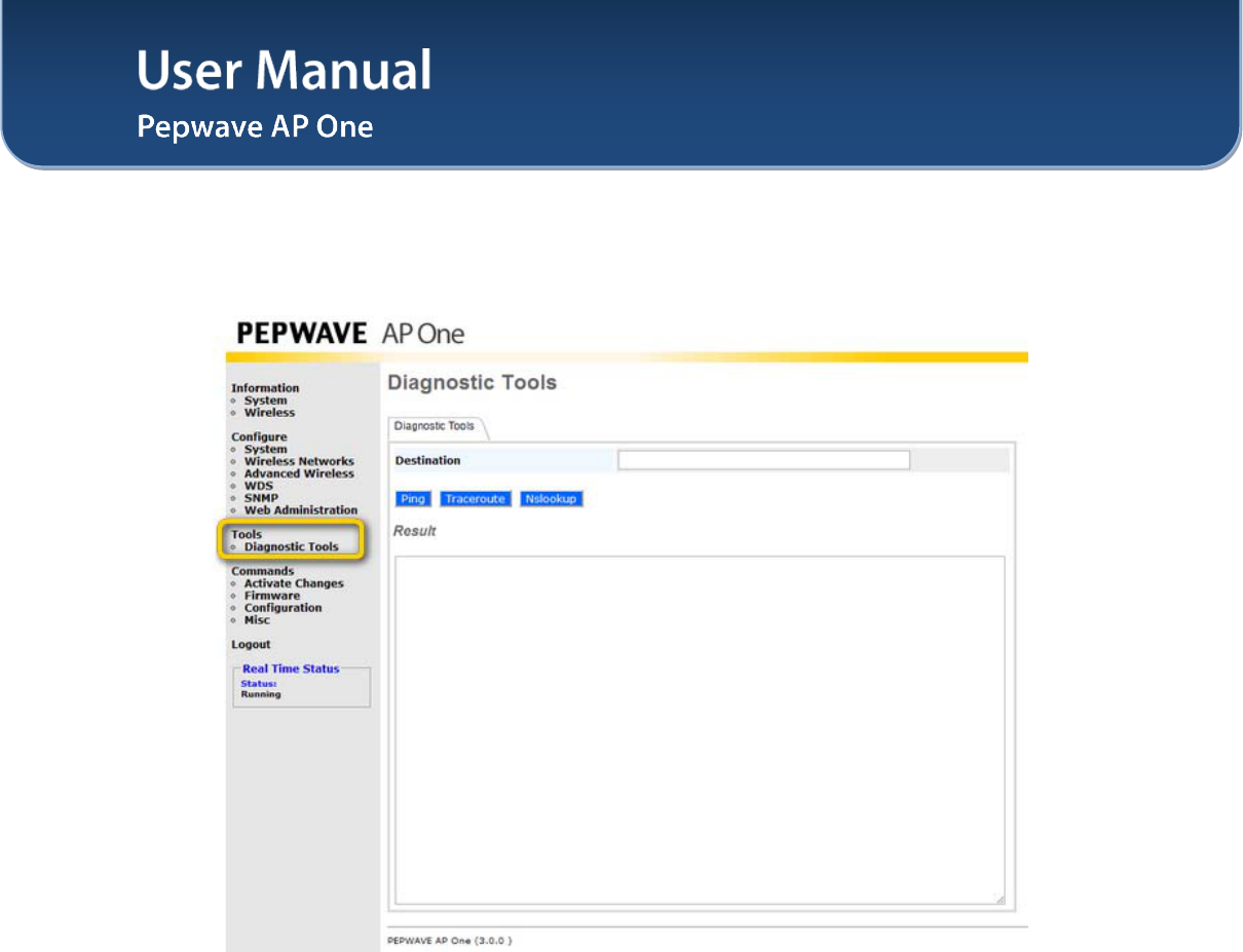
8 Tools - Diagnostic Tools
This provides three useful tools for diagnosing the network. The three available options are: Ping,
Traceroute and Nslookup.
User Manual
http://www.pepwave.com 37 Copyright © 2011
Pepwave
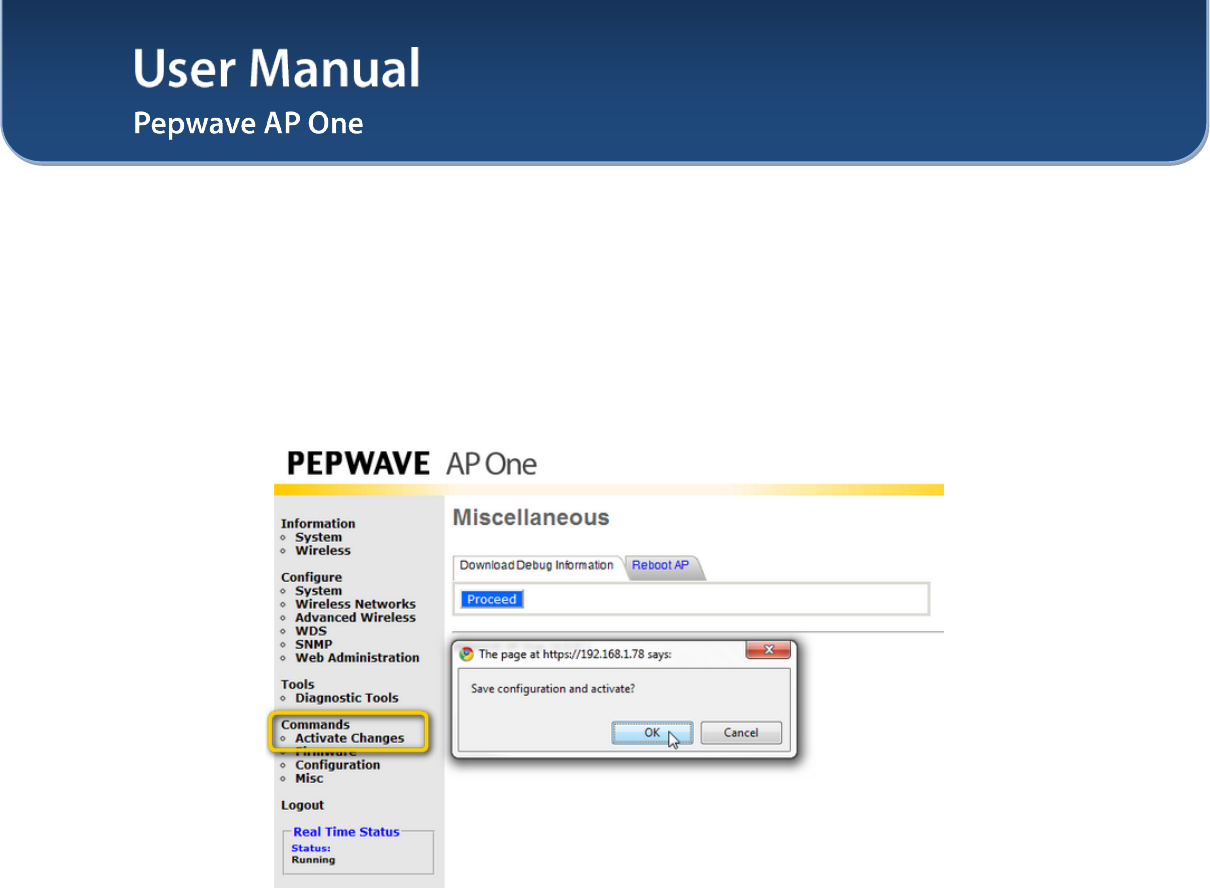
9 Commands
Upon selecting Commands from the navigation bar on the left-hand-side of the Main Menu, a list of
commands is displayed, as follows:
9.1 Activate Changes
Click on Activate Changes and a prompt will ask and confirm to save configuration and activate the AP
One unit.
User Manual
http://www.pepwave.com 38 Copyright © 2011
Pepwave
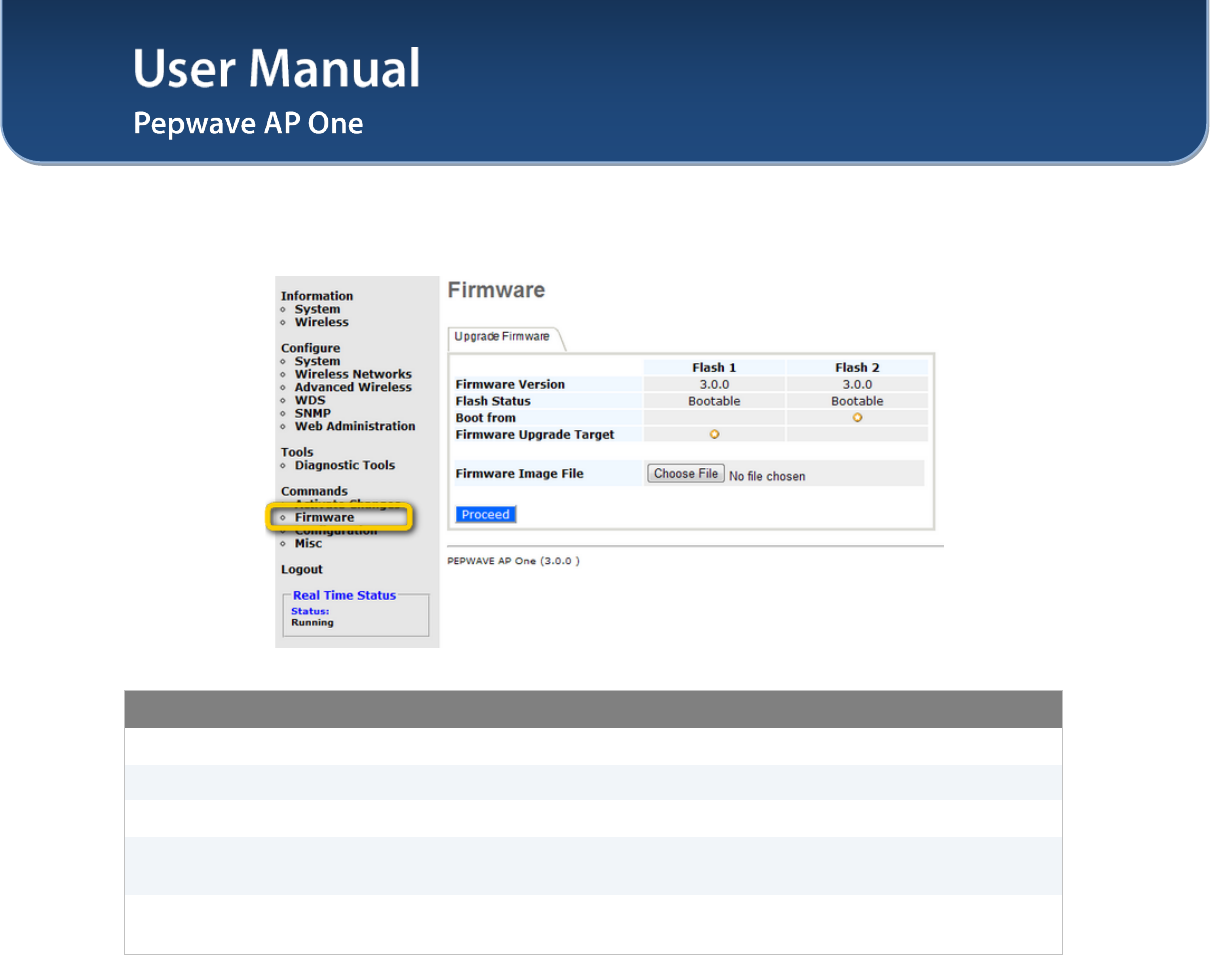
9.2 Firmware
Commands - Firmware
Firmware Version This shows the firmware version loaded into the flash partitions.
Flash Status This shows the firmware status on the flash partitions.
Boot from This indicates which flash partition boots up the system.
Firmware Upgrade
Target This shows which flash partition is used for firmware upgrade.
Firmware Image File Upload a firmware file for upgrading the unit’s software. A reboot is required
after upgrading the firmware.
User Manual
http://www.pepwave.com 39 Copyright © 2011
Pepwave
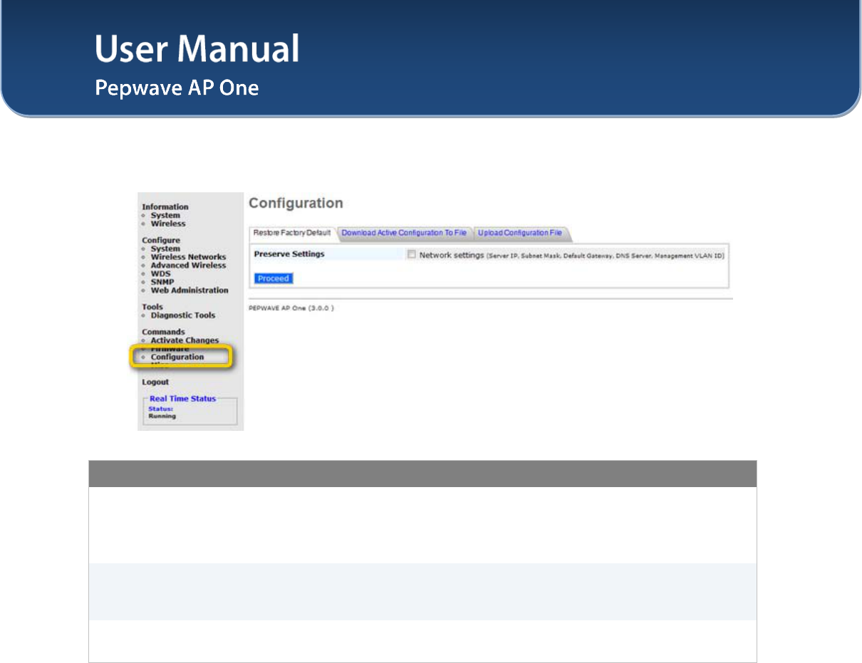
9.3 Configuration
Commands - Configuration
Restore Factory
Default
This command is for restoring factory default settings of the AP One. Preserve
the network settings by checking the box next to Preserve Settings and select
Proceed. Settings including Server IP, Subnet Mask, Default Gateway, DNS
Server and Management VLAN ID will be preserved.
Download Active
Configuration To
File
Select this command to download the active configuration for backup
purposes.
Upload
Configuration File
Select this command to upload the configuration from a backed up
configuration file.
User Manual
http://www.pepwave.com 40 Copyright © 2011
Pepwave
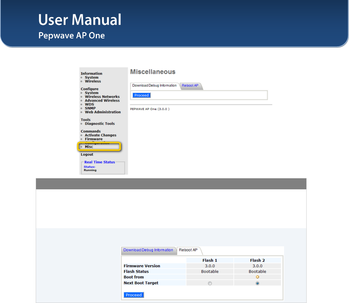
9.4 Misc
Commands - Misc
Download Debug
Information
Select this comment to download debugging information from the Pepwave AP
One unit.
In the event of technical issues, to facilitate prompt resolution by technical
support from Pepwave, please send along with a debug file with the support
request.
Reboot AP
This option is for rebooting the Pepwave AP One unit.
The Boot up firmware from Flash 1 or 2 can be selected and changed in here.
User Manual
http://www.pepwave.com 41 Copyright © 2011
Pepwave
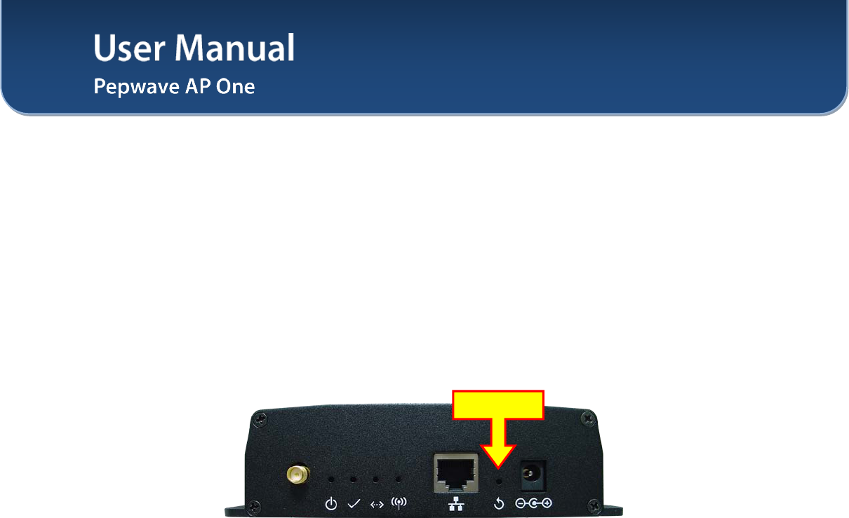
10 Restoration of Factory Defaults
10.1 AP One
The following procedure restores the settings of Pepwave AP One device to factory defaults:
1. Power on the unit, wait for 1 minute until the Status LED turns green.
2. Press and hold the reset button on the rear panel for at least 5 seconds, then release.
3. The Status LED will blink, and then the unit will automatically reboot.
4. Wait for 1 minute or until the Status LED turns green, upon which the settings of Pepwave AP
One will have been restored to the factory defaults.
By default, the unit will acquire an IP address from a DHCP server.
Reset Button
User Manual
http://www.pepwave.com 42 Copyright © 2011
Pepwave
Appendix A.
Federal Communication Commission Interference Statement
This equipment has been tested and found to comply with the limits for a Class B digital device, pursuant
to Part 15 of the FCC Rules. These limits are designed to provide reasonable protection against harmful
interference in a residential installation. This equipment generates, uses and can radiate radio frequency
energy and, if not installed and used in accordance with the instructions, may cause harmful interference
to radio communications. However, there is no guarantee that interference will not occur in a particular
installation. If this equipment does cause harmful interference to radio or television reception, which can
be determined by turning the equipment off and on, the user is encouraged to try to correct the
interference by one of the following measures:
1) Reorient or relocate the receiving antenna.
2) Increase the separation between the equipment and receiver.
3) Connect the equipment into an outlet on a circuit different from that to which the receiver is connected.
4) Consult the dealer or an experienced radio/TV technician for help.
This device complies with Part 15 of the FCC Rules. Operation is subject to the following two conditions:
(1) This device may not cause harmful interference, and (2) this device must accept any interference
received, including interference that may cause undesired operation.
FCC Caution: Any changes or modifications not expressly approved by the party responsible for
compliance could void the user's authority to operate this equipment.
IEEE 802.11b or 802.11g operation of this product in the U.S.A. is firmware-limited to channels 1 through
11.
IMPORTANT NOTE
FCC Radiation Exposure Statement
This equipment complies with FCC radiation exposure limits set forth for an uncontrolled environment.
This equipment should be installed and operated with minimum distance 20cm between the radiator &
your body.
This transmitter must not be co-located or operating in conjunction with any other antenna or transmitter.
The availability of some specific channels and/or operational frequency bands are country
dependent and are firmware programmed at the factory to match the intended destination.

Contact Us:
Sales
http://www.pepwave.com/contact/sales/
Support
http://www.pepwave.com/contact/
Business Development and
Partnerships
http://www.pepwave.com/partners/channel-
partner-program/
Address:
United States Office
800 West El Camino Real,
Mountain View
CA 94040
United States
Tel: +1 (650) 331 0641
Fax: +1 (650) 625 4664
Hong Kong Office
17/F, Park Building,
476 Castle Peak Road
Cheung Sha Wan
Hong Kong
Tel: +852 2990 7600
Fax: +852 3007 0588
www.pepwave.com