Pismolabs Technology P1AC8 Pepwave / Peplink / Pismo Labs Wireless Product User Manual Part 1
Pismo Labs Technology Limited Pepwave / Peplink / Pismo Labs Wireless Product Part 1
Contents
- 1. User Manual Part 1
- 2. User Manual Part 2
- 3. User Manual Part 3
- 4. User Manual Part 4 rev
User Manual Part 1

COPYRIGHT & TRADEMARKS
Specifications are subject to change without notice. Copyright © 2016 Pepwave Ltd. All Rights Reserved.
Pepwave and the Pepwave logo are trademarks of Pepwave Ltd. Other brands or products mentioned may
be trademarks or registered trademarks of their respective owners.
Pepwave MAX and Surf
User Manual
Pepwave Products:
MAX 700/HD2/HD2 IP67/HD2 mini/HD4/Transit/Hotspot/BR1/BR1 Mini/BR1 Slim/BR1
ENT/BR1 Pro LTE/BR1 IP55/BR2 IP55/On-The-Go/MAX HD2/HD4 with
MediaFast/Device Connector/ Surf SOHO
Pepwave Firmware 6.3
September 2016

Pepwave MAX and Surf User Manual
http://www.pepwave.com 2 Copyright @ 2016 Pepwave
Table of Contents
1 INTRODUCTION AND SCOPE ............................................................................................. 6
2 GLOSSARY........................................................................................................................ 7
3 PRODUCT FEATURES ........................................................................................................ 8
3.1 S
UPPORTED
N
ETWORK
F
EATURES
.................................................................................... 8
3.2 O
THER
S
UPPORTED
F
EATURES
...................................................................................... 10
4 PEPWAVE MAX MOBILE ROUTER OVERVIEW .................................................................. 11
4.1 MAX
700 ................................................................................................................ 11
4.2 MAX
HD2 ............................................................................................................... 13
4.3 MAX
HD2
IP67 ....................................................................................................... 15
4.4 MAX
HD2
MINI
........................................................................................................ 16
4.5 MAX
T
RANSIT
........................................................................................................... 18
4.6 MAX
H
OTSPOT
......................................................................................................... 19
4.7 MAX
HD4 ............................................................................................................... 20
4.8 MAX
BR1 ................................................................................................................ 22
4.9 MAX
BR1
M
INI
........................................................................................................ 24
4.10 MAX
BR1
S
LIM
........................................................................................................ 25
4.11 MAX
BR1
ENT ........................................................................................................ 27
4.12 MAX
BR1
P
RO
LTE ................................................................................................... 28
4.13 MAX
BR1/2
IP55 .................................................................................................... 29
4.14 MAX
O
N
-T
HE
-G
O
..................................................................................................... 31
4.15 S
URF
SOHO ............................................................................................................. 32
5 ADVANCED FEATURE SUMMARY .................................................................................... 33
5.1 D
ROP
-
IN
M
ODE AND
LAN
B
YPASS
:
T
RANSPARENT
D
EPLOYMENT
........................................ 33
5.2 Q
O
S:
C
LEARER
V
O
IP .................................................................................................. 33
5.3 P
ER
-U
SER
B
ANDWIDTH
C
ONTROL
................................................................................. 34
5.4 H
IGH
A
VAILABILITY VIA
VRRP ...................................................................................... 34
5.5 USB
M
ODEM AND
A
NDROID
T
ETHERING
........................................................................ 35
5.6 B
UILT
-I
N
R
EMOTE
U
SER
VPN
S
UPPORT
......................................................................... 35
5.7 SIM-
CARD
USSD
SUPPORT
.......................................................................................... 36
6 INSTALLATION ............................................................................................................... 37
6.1 P
REPARATION
............................................................................................................ 37
6.2 C
ONSTRUCTING THE
N
ETWORK
..................................................................................... 38
6.3 C
ONFIGURING THE
N
ETWORK
E
NVIRONMENT
.................................................................. 39
7 MOUNTING THE UNIT .................................................................................................... 40
7.1 W
ALL
M
OUNT
........................................................................................................... 40
7.2 C
AR
M
OUNT
............................................................................................................. 40

Pepwave MAX and Surf User Manual
http://www.pepwave.com 3 Copyright @ 2016 Pepwave
7.3 IP67
I
NSTALLATION
G
UIDE
.......................................................................................... 40
8 CONNECTING TO THE WEB ADMIN INTERFACE ............................................................... 41
9 CONFIGURING THE LAN INTERFACE(S) ............................................................................ 43
9.1 B
ASIC
S
ETTINGS
......................................................................................................... 43
9.2 C
APTIVE
P
ORTAL
........................................................................................................ 53
10 CONFIGURING THE WAN INTERFACE(S) .......................................................................... 55
10.1 E
THERNET
WAN ....................................................................................................... 56
10.2 C
ELLULAR
WAN ........................................................................................................ 64
10.3 W
I
-F
I
WAN ............................................................................................................. 69
10.4 WAN
H
EALTH
C
HECK
................................................................................................. 75
10.5 D
YNAMIC
DNS
S
ETTINGS
............................................................................................ 77
11 ADVANCED WI-FI SETTINGS ............................................................................................ 80
12 MEDIAFAST CONFIGURATION ........................................................................................ 83
12.1 S
ETTING
U
P
M
EDIA
F
AST
C
ONTENT
C
ACHING
.................................................................. 83
12.2 S
CHEDULING
C
ONTENT
P
REFETCHING
............................................................................. 84
12.3 V
IEWING
M
EDIA
F
AST
S
TATISTICS
.................................................................................. 85
13 BANDWIDTH BONDING SPEEDFUSION
TM
/ PEPVPN ......................................................... 87
13.1 P
EP
VPN .................................................................................................................. 88
13.2 T
HE
P
EPWAVE
R
OUTER
B
EHIND A
NAT
R
OUTER
.............................................................. 94
13.3 S
PEED
F
USIONTM
S
TATUS
............................................................................................. 95
14 IPSEC VPN ...................................................................................................................... 96
14.1 IP
SEC
VPN
S
ETTINGS
.................................................................................................. 96
15 OUTBOUND POLICY MANAGEMENT .............................................................................. 100
15.1 O
UTBOUND
P
OLICY
.................................................................................................. 100
15.2 C
USTOM
R
ULES FOR
O
UTBOUND
P
OLICY
...................................................................... 101
16 INBOUND ACCESS ......................................................................................................... 110
16.1 P
ORT
F
ORWARDING
S
ERVICE
...................................................................................... 110
17 NAT MAPPINGS ............................................................................................................ 113
18 QOS 115
18.1 U
SER
G
ROUPS
......................................................................................................... 115
18.2 B
ANDWIDTH
C
ONTROL
.............................................................................................. 116
18.3 A
PPLICATION
........................................................................................................... 116
19 FIREWALL ..................................................................................................................... 118
19.1 O
UTBOUND AND
I
NBOUND
F
IREWALL
R
ULES
................................................................. 118
19.2 C
ONTENT
B
LOCKING
................................................................................................. 123

Pepwave MAX and Surf User Manual
http://www.pepwave.com 4 Copyright @ 2016 Pepwave
19.3 OSPF
&
RIP
V
2 ....................................................................................................... 124
19.4 R
EMOTE
U
SER
A
CCESS
.............................................................................................. 126
MISCELLANEOUS SETTINGS ................................................................................................. 128
19.5 H
IGH
A
VAILABILITY
................................................................................................... 128
19.6 PPTP
S
ERVER
......................................................................................................... 131
19.7 C
ERTIFICATE
M
ANAGER
............................................................................................. 132
19.8 S
ERVICE
F
ORWARDING
.............................................................................................. 132
19.9 S
ERVICE
P
ASSTHROUGH
............................................................................................. 135
19.10 GPS
F
ORWARDING
................................................................................................... 136
20 AP CONTROLLER ........................................................................................................... 137
20.1 W
IRELESS
SSID ....................................................................................................... 137
20.2 S
ETTINGS
................................................................................................................ 141
20.3 T
OOLBOX
................................................................................................................ 145
21 SYSTEM SETTINGS ......................................................................................................... 146
21.1 A
DMIN
S
ECURITY
..................................................................................................... 146
21.2 F
IRMWARE
.............................................................................................................. 151
21.3 T
IME
...................................................................................................................... 152
21.4 S
CHEDULE
............................................................................................................... 152
21.5 E
MAIL
N
OTIFICATION
................................................................................................ 153
21.6 E
VENT
L
OG
............................................................................................................. 155
21.7 SNMP ................................................................................................................... 157
21.8 I
N
C
ONTROL
............................................................................................................. 159
21.9 C
ONFIGURATION
...................................................................................................... 159
21.10 F
EATURE
A
DD
-
ONS
................................................................................................... 161
21.11 R
EBOOT
................................................................................................................. 161
21.12 P
ING
...................................................................................................................... 162
21.13 T
RACEROUTE
T
EST
.................................................................................................... 163
21.14 P
EP
VPN
T
EST
......................................................................................................... 163
21.15 W
AKE
-
ON
-LAN ....................................................................................................... 164
21.16 CLI
(C
OMMAND
L
INE
I
NTERFACE
S
UPPORT
) .................................................................. 164
22 STATUS ......................................................................................................................... 165
22.1 D
EVICE
................................................................................................................... 165
22.2 A
CTIVE
S
ESSIONS
..................................................................................................... 167
22.3 C
LIENT
L
IST
............................................................................................................. 169
22.4 WINS
C
LIENT
......................................................................................................... 169
22.5 UP
N
P
/
NAT-PMP ................................................................................................. 170
22.6 S
PEED
F
USION
S
TATUS
............................................................................................... 170
22.7 E
VENT
L
OG
............................................................................................................. 174
22.8 B
ANDWIDTH
........................................................................................................... 174
APPENDIX A. RESTORATION OF FACTORY DEFAULTS ...................................................... 180

Pepwave MAX and Surf User Manual
http://www.pepwave.com 5 Copyright @ 2016 Pepwave
APPENDIX B: DECLARATION ................................................................................................ 181

Pepwave MAX and Surf User Manual
http://www.pepwave.com 6 Copyright @ 2016 Pepwave
1 Introduction and Scope
Pepwave routers provide link aggregation and load balancing across multiple WAN
connections, allowing a combination of technologies like 3G HSDPA, EVDO, 4G LTE,
Wi-Fi, external WiMAX dongle, and satellite to be utilized to connect to the Internet.
The MAX wireless SD-WAN router series has a wide range of products suitable for
many different deployments and markets. Entry level SD-WAN models such as the MAX
BR1 are suitable for SMEs or branch offices. High-capacity SD-WAN routers such as
the MAX HD2 are suitable for larger organizations and head offices.
This manual covers setting up Pepwave routers and provides an introduction to their
features and usage.
Tips
Want to know more about Pepwave routers? Visit our YouTube Channel for a video introduction!
http://youtu.be/UCkVQThLKO4

Pepwave MAX and Surf User Manual
http://www.pepwave.com 7 Copyright @ 2016 Pepwave
2 Glossary
The following terms, acronyms, and abbreviations are frequently used in this manual:
Term Definition
3G 3rd Generation standards for wireless communications
4G 4th Generation standards for wireless communications
DHCP Dynamic Host Configuration Protocol
DNS Domain Name System
EVDO Evolution-Data Optimized
HSDPA High-Speed Downlink Packet Access
HTTP Hyper-Text Transfer Protocol
ICMP Internet Control Message Protocol
IP Internet Protocol
LAN Local Area Network
MAC Address Media Access Control Address
MTU Maximum Transmission Unit
MSS Maximum Segment Size
NAT Network Address Translation
PPPoE Point to Point Protocol over Ethernet
QoS Quality of Service
SNMP Simple Network Management Protocol
TCP Transmission Control Protocol
UDP User Datagram Protocol
VPN Virtual Private Network
VRRP Virtual Router Redundancy Protocol
WAN Wide Area Network
WINS Windows Internet Name Service
WLAN Wireless Local Area Network

Pepwave MAX and Surf User Manual
http://www.pepwave.com 8 Copyright @ 2016 Pepwave
3 Product Features
Pepwave routers enable all LAN users to share broadband Internet connections, and
they provide advanced features to enhance Internet access. Our Max BR wireless
routers support multiple SIM cards. They can be configured to switch from using one
SIM card to another SIM card according to different criteria, including wireless network
reliability and data usage.
Our MAX HD series wireless routers are embedded with multiple 4G LTE modems, and
allow simultaneous wireless Internet connections through multiple wireless networks.
The wireless Internet connections can be bonded together using our SpeedFusion
technology. This allows better reliability, larger bandwidth, and increased wireless
coverage are comparing to use only one 4G LTE modem.
Below is a list of supported features on Pepwave routers. Features vary by model. For
more information, please see peplink.com/products.
3.1 Supported Network Features
3.1.1 WAN
Ethernet WAN connection in full/half duplex
Static IP support for PPPoE
Built-in HSPA and EVDO cellular modems
USB mobile connection(s)
Wi-Fi WAN connection
Network address translation (NAT)/port address translation (PAT)
Inbound and outbound NAT mapping
IPsec NAT-T and PPTP packet passthrough
MAC address clone and passthrough
Customizable MTU and MSS values
WAN connection health check
Dynamic DNS (supported service providers: changeip.com, dyndns.org, no-
ip.org, tzo.com and DNS-O-Matic)
Ping, DNS lookup, and HTTP-based health check
3.1.2 LAN
Wi-Fi AP
Ethernet LAN ports
DHCP server on LAN
Extended DHCP option support
Static routing rules
VLAN on LAN support

Pepwave MAX and Surf User Manual
http://www.pepwave.com 9 Copyright @ 2016 Pepwave
3.1.3 VPN
PepVPN with SpeedFusion
TM
PepVPN performance analyzer
X.509 certificate support
VPN load balancing and failover among selected WAN connections
Bandwidth bonding and failover among selected WAN connections
IPsec VPN for network-to-network connections (works with Cisco and Juniper
only)
Ability to route Internet traffic to a remote VPN peer
Optional pre-shared key setting
SpeedFusion
TM
throughput, ping, and traceroute tests
PPTP server
PPTP and IPsec passthrough
3.1.4 Firewall
Outbound (LAN to WAN) firewall rules
Inbound (WAN to LAN) firewall rules per WAN connection
Intrusion detection and prevention
Specification of NAT mappings
Outbound firewall rules can be defined by destination domain name
3.1.5 Captive Portal
Splash screen of open networks, login page for secure networks
Customizable built-in captive portal
Supports linking to outside page for captive portal
3.1.6 Outbound Policy
Link load distribution per TCP/UDP service
Persistent routing for specified source and/or destination IP addresses per
TCP/UDP service
Traffic prioritization and DSL optimization
Prioritize and route traffic to VPN tunnels with Priority and Enforced algorithms
3.1.7 AP Controller
Configure and manage Pepwave AP devices

Pepwave MAX and Surf User Manual
http://www.pepwave.com 10 Copyright @ 2016 Pepwave
Review the status of connected APs
3.1.8 QoS
Quality of service for different applications and custom protocols
User group classification for different service levels
Bandwidth usage control and monitoring on group- and user-level
Application prioritization for custom protocols and DSL/cable optimization
3.2 Other Supported Features
User-friendly web-based administration interface
HTTP and HTTPS support for web admin interface
Configurable web administration port and administrator password
Firmware upgrades, configuration backups, ping, and traceroute via web admin
interface
Remote web-based configuration (via WAN and LAN interfaces)
Time server synchronization
SNMP
Email notification
Read-only user for web admin
Shared IP drop-in mode
Authentication and accounting by RADIUS server for web admin
Built-in WINS servers*
Syslog
SIP passthrough
PPTP packet passthrough
Event log
Active sessions
Client list
WINS client list *
UPnP / NAT-PMP
Real-time, hourly, daily, and monthly bandwidth usage reports and charts
IPv6 support
Support USB tethering on Android 2.2+ phones
* Not supported on MAX Surf-On-The-Go, Surf SOHO, and BR1 variants
Pepwave MAX and Surf User Manual
http://www.pepwave.com 11 Copyright @ 2016 Pepwave
4 Pepwave MAX Mobile Router Overview
4.1 MAX 700
4.1.1 Panel Appearance

Pepwave MAX and Surf User Manual
http://www.pepwave.com 12 Copyright @ 2016 Pepwave
4.1.2 LED Indicators
The statuses indicated by the front panel LEDs are as follows:
Status Indicators
Status
OFF System initializing
Red Booting up or busy
Blinking
red Boot up error
Green Ready
Wi-Fi AP and Wi-Fi WAN Indicators
Wi-Fi WAN
OFF Disconnected
Blinking slowly Connecting to network
Blinking Connected to network with traffic
ON Connected to network without traffic
Wi-Fi AP
OFF Disabled
Blinking slowly Enabled but no client connected
Blinking Connected to network with traffic
ON Client(s) connected to wireless network
LAN and Ethernet WAN Ports
Green LED ON 10 / 100/ 1000 Mbps
Orange LED
Blinking Data is transferring
OFF No data is being transferred or port is not
connected
Port Type Auto MDI/MDI-X ports
Pepwave MAX and Surf User Manual
http://www.pepwave.com 13 Copyright @ 2016 Pepwave
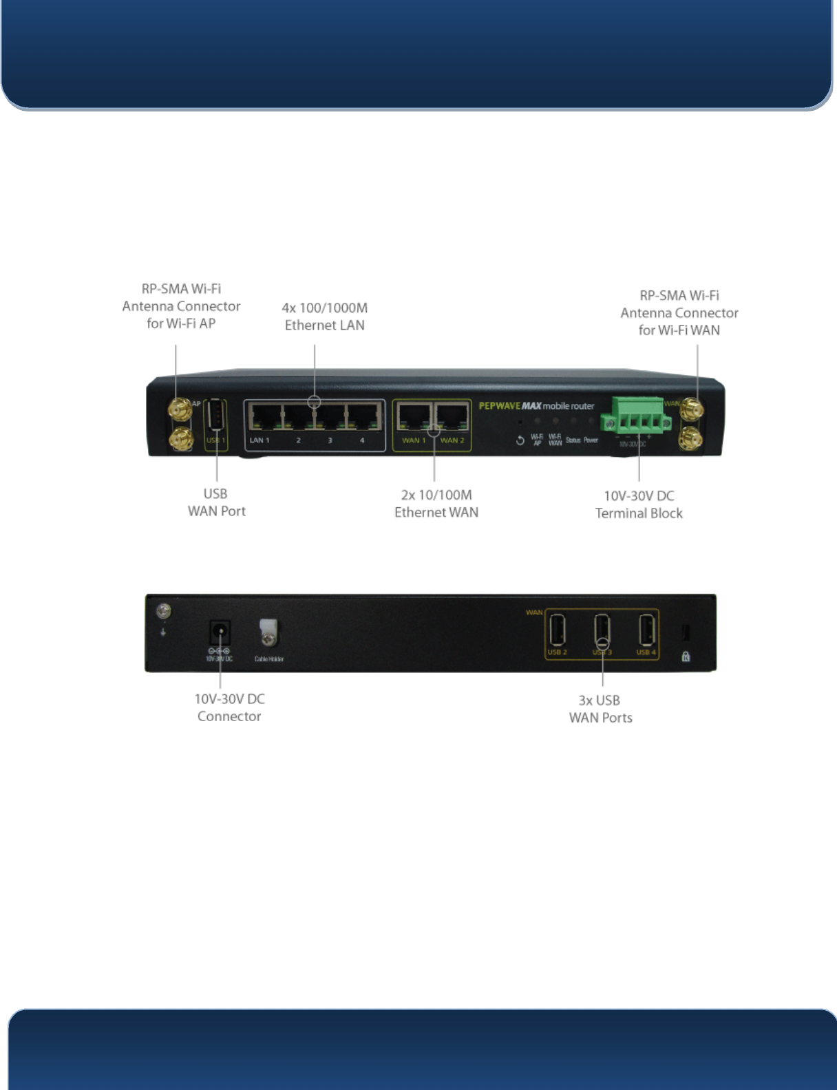
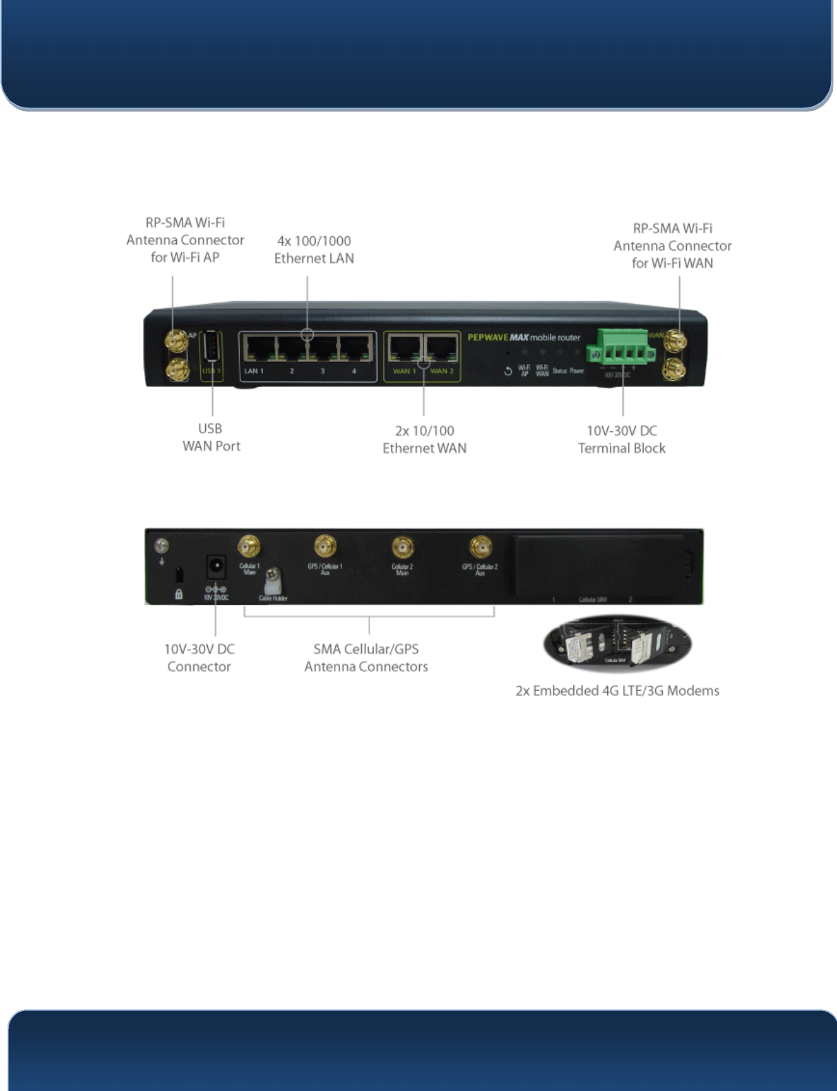
4.2 MAX HD2
4.2.1 Panel Appearance

Pepwave MAX and Surf User Manual
http://www.pepwave.com 14 Copyright @ 2016 Pepwave
4.2.2 LED Indicators
The statuses indicated by the front panel LEDs are as follows:
Status Indicators
Status
OFF System initializing
Red Booting up or busy
Blinking
red Boot up error
Green Ready
Wi-Fi AP and Wi-Fi WAN Indicators
Wi-Fi WAN /
Cellular 1 /
Cellular 2
OFF Disabled Intermittent
Blinking slowly Connecting to wireless network(s)
Blinking Connected to wireless network(s) with traffic
ON Connected to wireless network(s) without traffic
LAN and Ethernet WAN Ports
Green LED ON 10 / 100 / 1000 Mbps
Orange LED
Blinking Data is transferring
OFF No data is being transferred or port is not
connected
Port Type Auto MDI/MDI-X ports
Pepwave MAX and Surf User Manual
http://www.pepwave.com 15 Copyright @ 2016 Pepwave
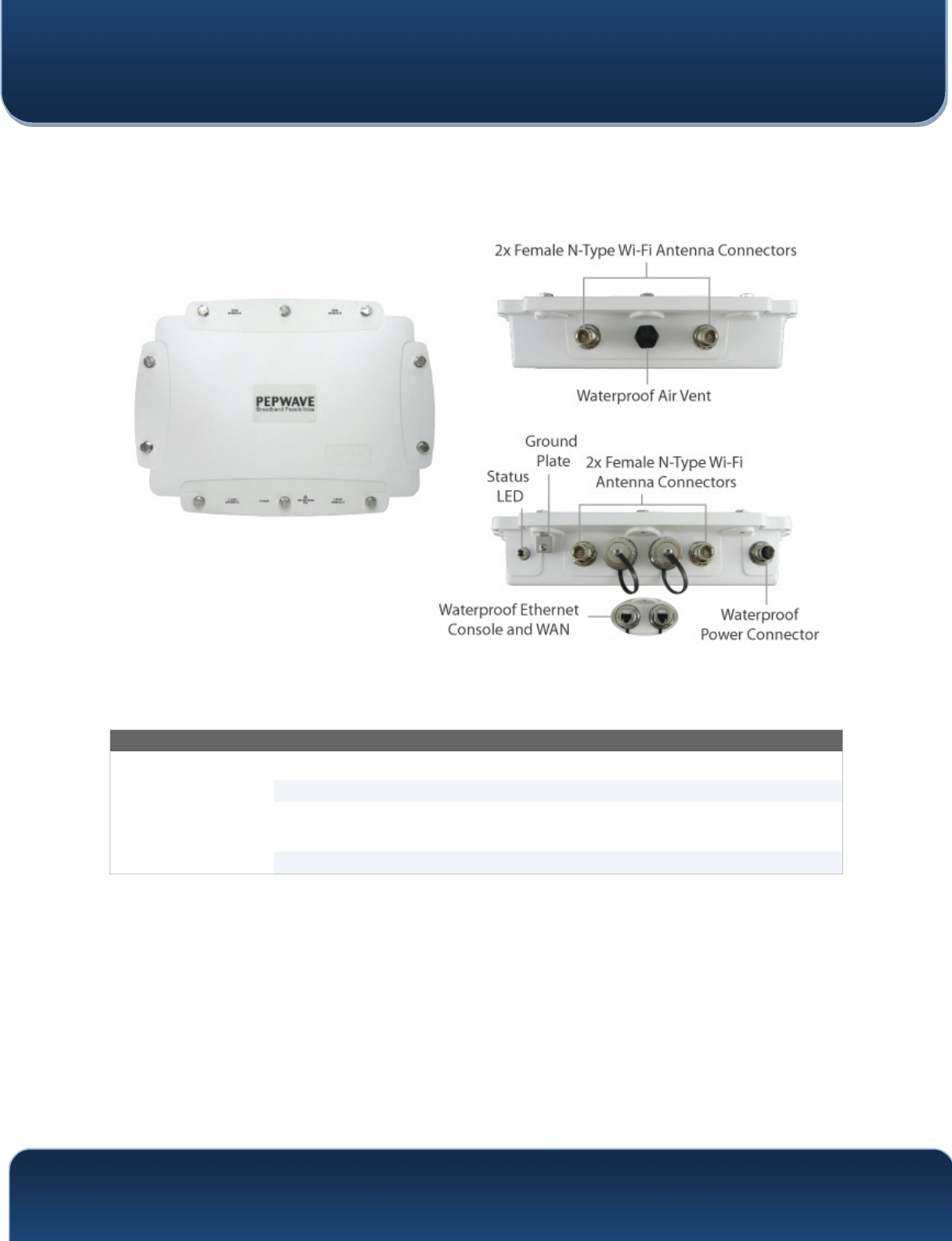
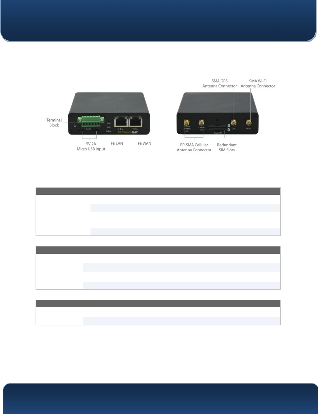
4.3 MAX HD2 IP67
4.3.1 Panel Appearance
The statuses indicated by the front panel LEDs are as follows:
Status Indicators
Status
OFF System initializing
Red Booting up or busy
Blinking
red Boot up error
Green Ready
Pepwave MAX and Surf User Manual
http://www.pepwave.com 16 Copyright @ 2016 Pepwave
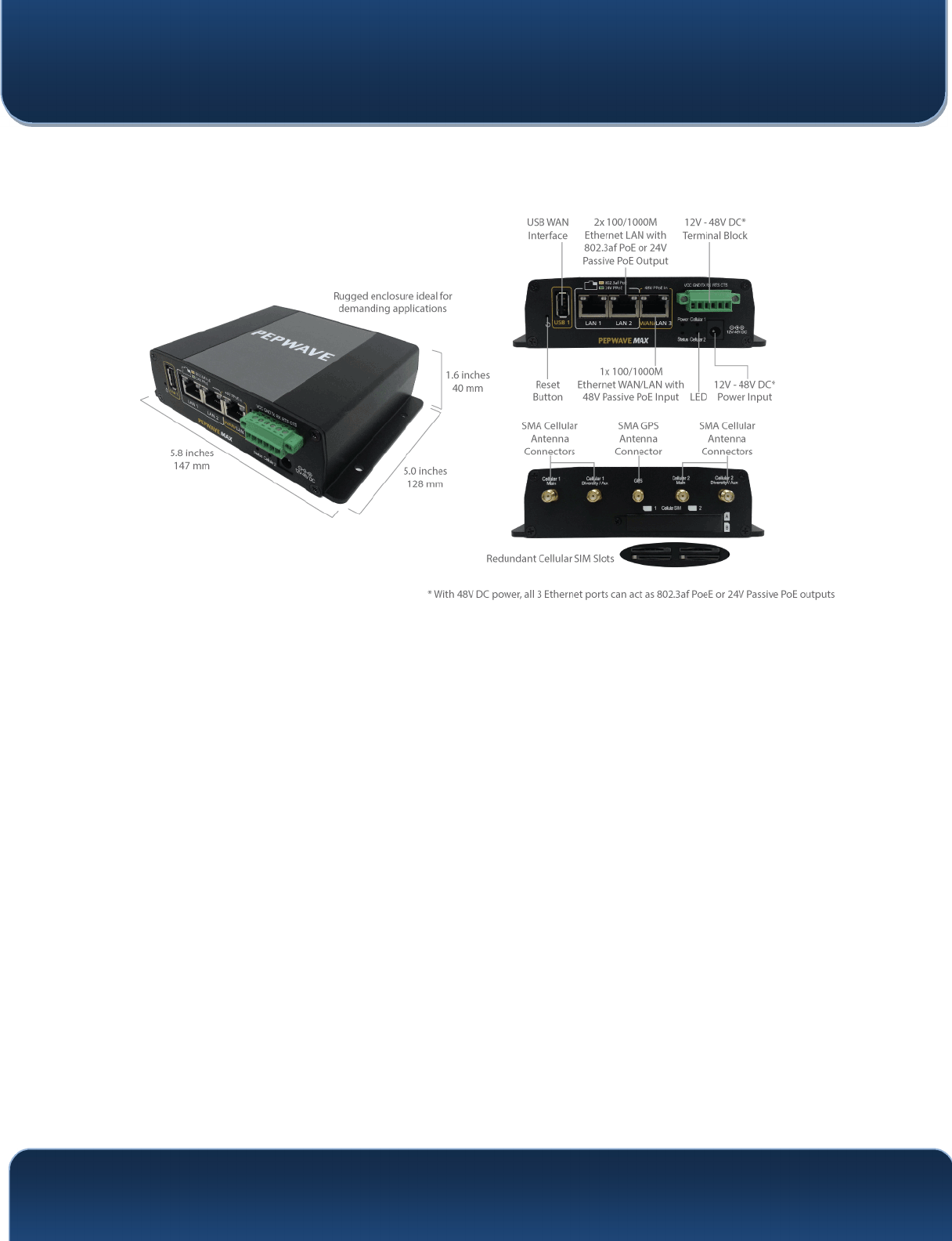
4.4 MAX HD2 mini
4.4.1 Panel Appearance

Pepwave MAX and Surf User Manual
http://www.pepwave.com 17 Copyright @ 2016 Pepwave
4.4.2 LED Indicators
The statuses indicated by the front panel LEDs are as follows:
Status Indicators
Status
OFF System initializing
Red Booting up or busy
Blinking
red Boot up error
Green Ready
Cellular WAN Indicators
Cellular 1 /
Cellular 2
OFF Disabled intermittent
Blinking slowly Connecting to wireless network(s)
Blinking Connected to wireless network(s) with traffic
ON Connected to wireless network(s) without traffic
LAN and Ethernet WAN Ports
Green LED ON 10 / 100 / 1000 Mbps
Orange LED
Blinking Data is transferring
OFF No data is being transferred or port is not
connected
Port Type Auto MDI/MDI-X ports
Pepwave MAX and Surf User Manual
http://www.pepwave.com 18 Copyright @ 2016 Pepwave
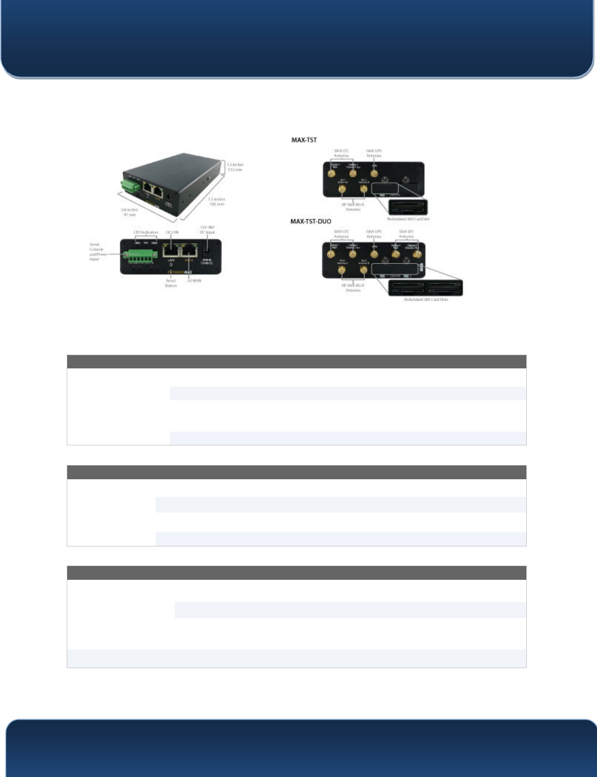
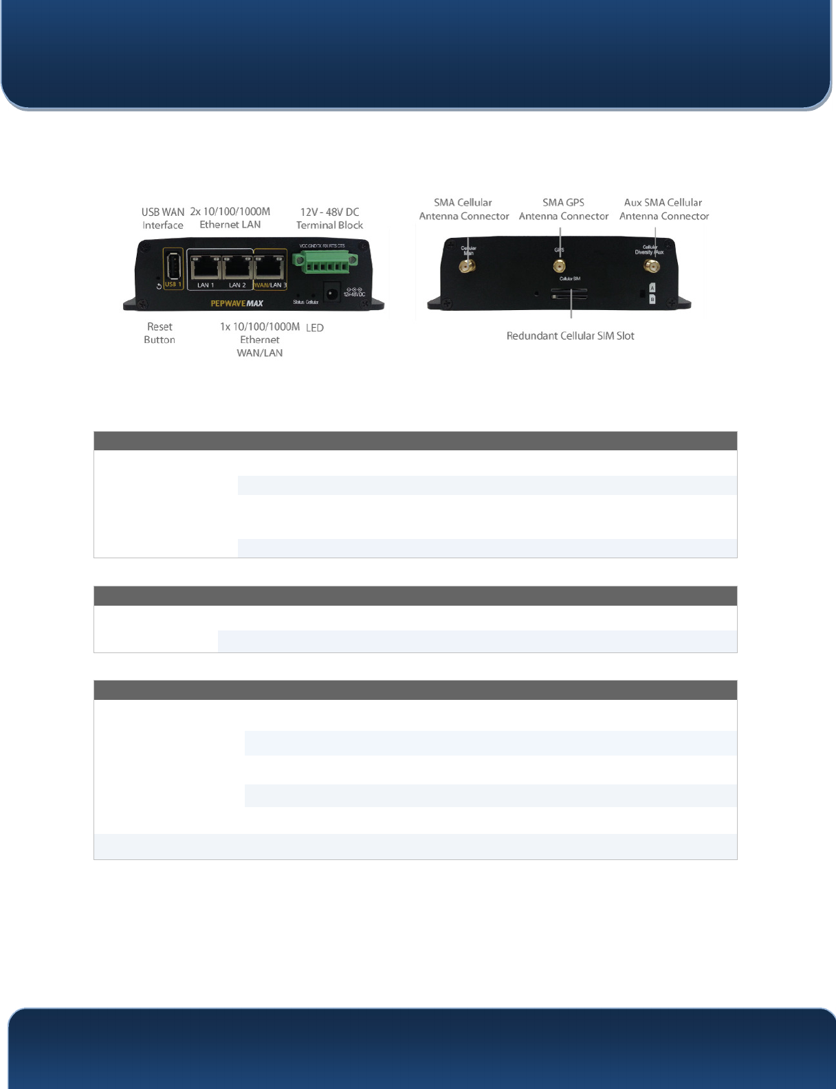
4.5 MAX Transit
4.5.1 Panel Appearance
4.5.2 LED Indicators
The statuses indicated by the front panel LEDs are as follows:
Status Indicators
Status
OFF System initializing
Red Booting up or busy
Blinking
red Boot up error
Green Ready
Cellular WAN Indicators
Cellular 1 /
Cellular 2*
OFF Disabled intermittent
Blinking slowly Connecting to wireless network(s)
Blinking Connected to wireless network(s) with traffic
ON Connected to wireless network(s) without traffic
* For MAX-TST_DUO
LAN and Ethernet WAN Ports
Green LED ON 10 / 100 / 1000 Mbps
Orange LED
Blinking Data is transferring
OFF No data is being transferred or port is not
connected
Port Type Auto MDI/MDI-X ports
Pepwave MAX and Surf User Manual
http://www.pepwave.com 19 Copyright @ 2016 Pepwave
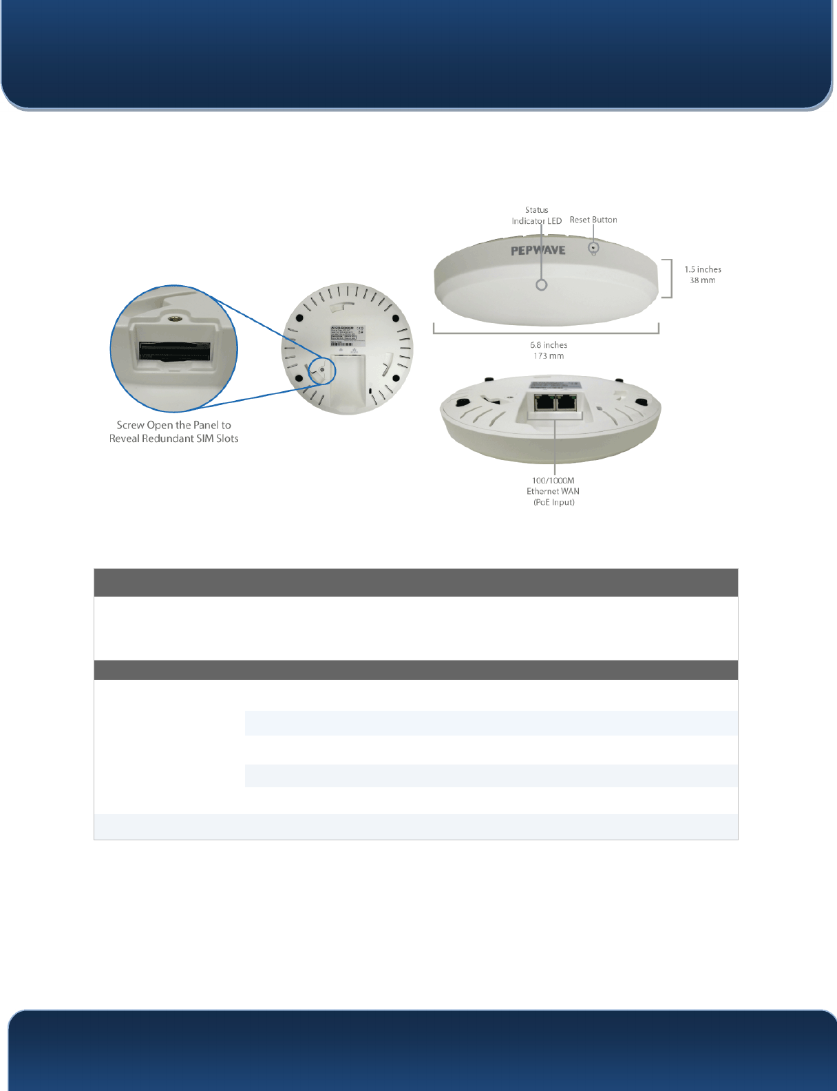
4.6 MAX Hotspot
4.6.1 Panel Appearance
4.6.2 LED Indications
LED Indicators
Status RED – Access point initializing
GREEN – Access point ready
LAN and Ethernet WAN Ports
Green LED ON 100 Mbps
OFF 10 Mbps
Orange LED
ON Port is connected without traffic
Blinking Data is transferring
OFF Port is not connected
Port Type Auto MDI/MDI-X ports
Pepwave MAX and Surf User Manual
http://www.pepwave.com 20 Copyright @ 2016 Pepwave
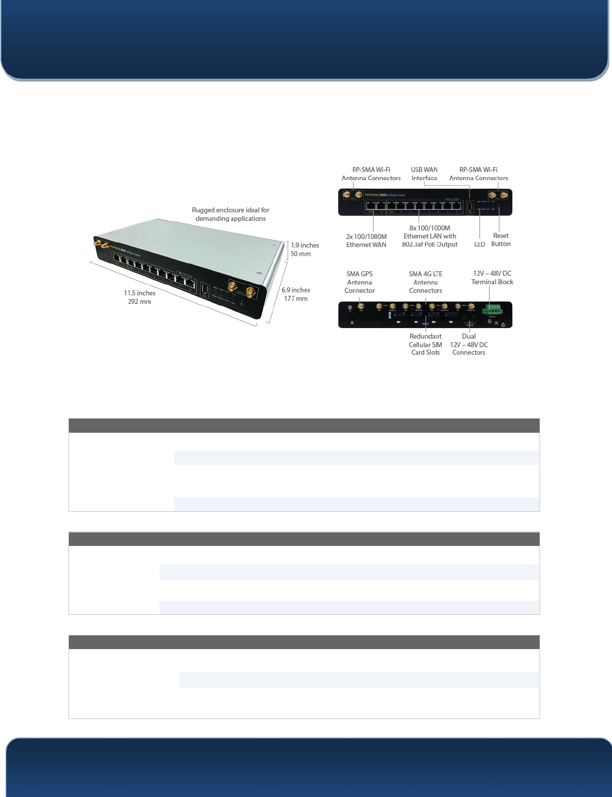
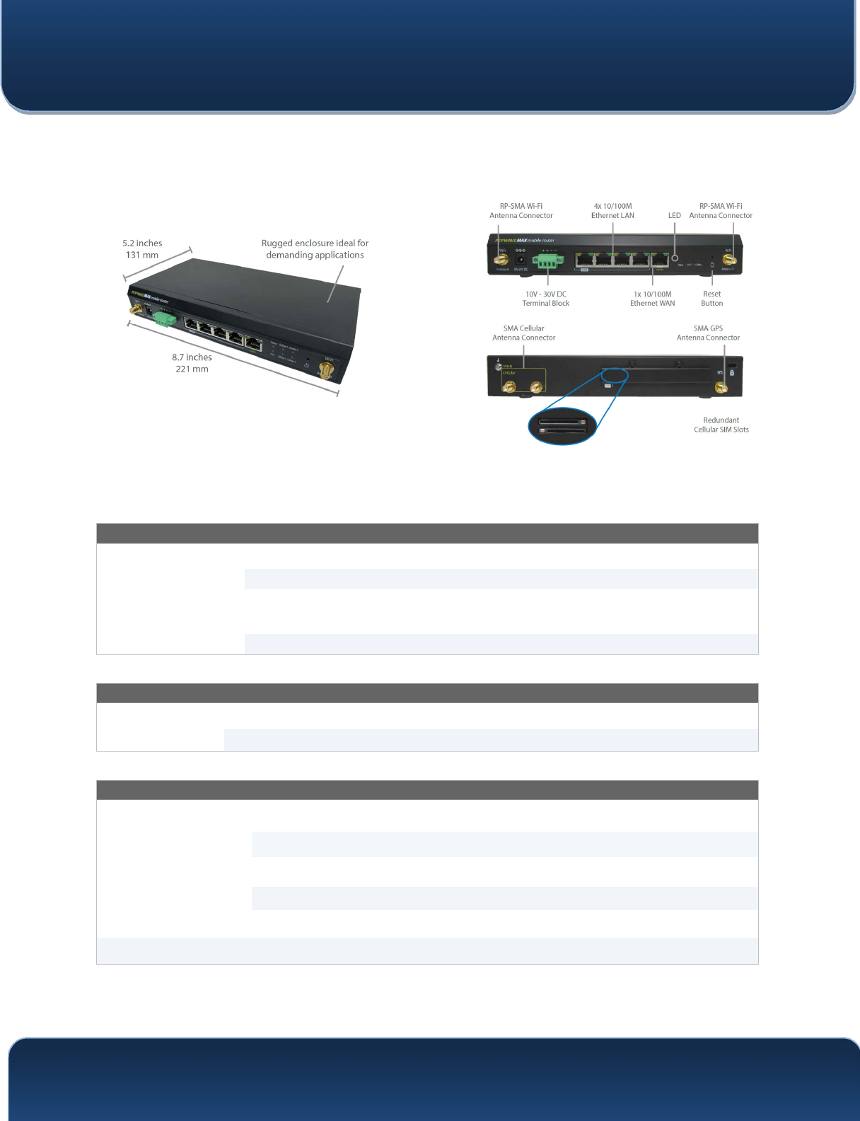
4.7 MAX HD4
4.7.1 Panel Appearance
4.7.2 LED Indicators
The statuses indicated by the front panel LEDs are as follows:
Status Indicators
Status
OFF System initializing
Red Booting up or busy
Blinking
red Boot up error
Green Ready
Wi-Fi AP and Wi-Fi WAN Indicators
Wi-Fi WAN /
Cellular 1 /
Cellular 2
OFF Disabled Intermittent
Blinking slowly Connecting to wireless network(s)
Blinking Connected to wireless network(s) with traffic
ON Connected to wireless network(s) without traffic
LAN and Ethernet WAN Ports
Green LED ON 10 / 100 / 1000 Mbps
Orange LED
Blinking Data is transferring
OFF No data is being transferred or port is not
connected

Pepwave MAX and Surf User Manual
http://www.pepwave.com 21 Copyright @ 2016 Pepwave
Port Type Auto MDI/MDI-X ports
Pepwave MAX and Surf User Manual
http://www.pepwave.com 22 Copyright @ 2016 Pepwave
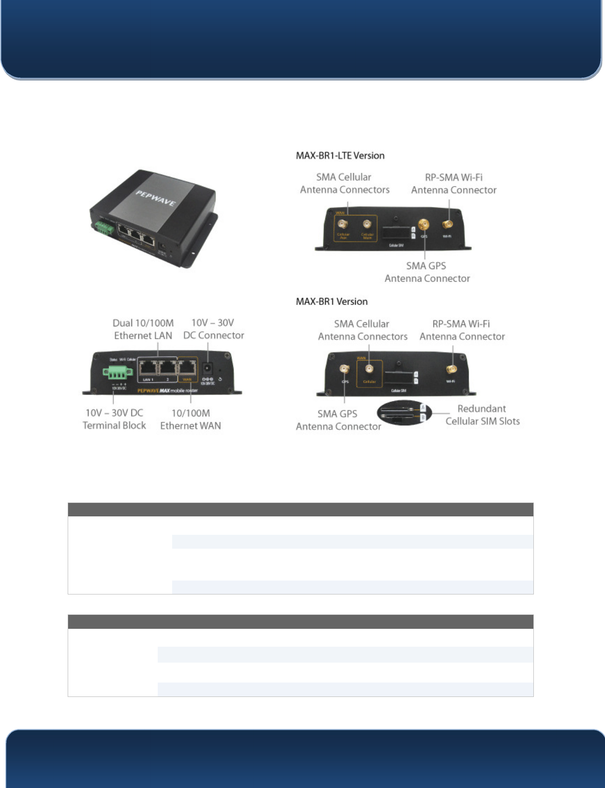
4.8 MAX BR1
4.8.1 Panel Appearance
4.8.2 LED Indicators
The statuses indicated by the front panel LEDs are as follows:
Status Indicators
Status
OFF System initializing
Red Booting up or busy
Blinking
red Boot up error
Green Ready
Wi-Fi Indicators
Wi-Fi
OFF Disabled intermittent
Blinking slowly Connecting to wireless network(s)
Blinking Connected to wireless network(s) with traffic
ON Connected to wireless network(s) without traffic

Pepwave MAX and Surf User Manual
http://www.pepwave.com 23 Copyright @ 2016 Pepwave
Cellular Indicators
Cellular OFF Disabled or no SIM card inserted
ON Connecting or connected to network(s)
LAN and Ethernet WAN Ports
Green LED ON 100 Mbps
OFF 10 Mbps
Orange LED
ON Port is connected without traffic
Blinking Data is transferring
OFF Port is not connected
Port Type Auto MDI/MDI-X ports

Pepwave MAX and Surf User Manual
http://www.pepwave.com 24 Copyright @ 2016 Pepwave
4.9 MAX BR1 Mini
4.9.1 Panel Appearance
4.9.2 LED Indicators
The statuses indicated by the front panel LEDs are as follows:
Status Indicators
Status
OFF System initializing
Red Booting up or busy
Blinking
red Boot up error
Green Ready
Wi-Fi Indicators
Wi-Fi
OFF Disabled intermittent
Blinking slowly Connecting to wireless network(s)
Blinking Connected to wireless network(s) with traffic
ON Connected to wireless network(s) without traffic
Cellular Indicators
Cellular OFF Disabled or no SIM card inserted
ON Connecting or connected to network(s)
Pepwave MAX and Surf User Manual
http://www.pepwave.com 25 Copyright @ 2016 Pepwave
4.10 MAX BR1 Slim
4.10.1 Panel Appearance
4.10.2 LED Indicators
The statuses indicated by the front panel LEDs are as follows:
Status Indicators
Status
OFF System initializing
Red Booting up or busy
Blinking
red Boot up error
Green Ready
Wi-Fi Indicators
Wi-Fi
OFF Disabled intermittent
Blinking slowly Connecting to wireless network(s)
Blinking Connected to wireless network(s) with traffic
ON Connected to wireless network(s) without traffic
Cellular Indicators
Cellular OFF Disabled or no SIM card inserted
ON Connecting or connected to network(s)

Pepwave MAX and Surf User Manual
http://www.pepwave.com 26 Copyright @ 2016 Pepwave
LAN and Ethernet WAN Ports
Green LED ON 100 Mbps
OFF 10 Mbps
Orange LED
ON Port is connected without traffic
Blinking Data is transferring
OFF Port is not connected
Port Type Auto MDI/MDI-X ports
Pepwave MAX and Surf User Manual
http://www.pepwave.com 27 Copyright @ 2016 Pepwave
4.11 MAX BR1 ENT
4.11.1 Panel Appearance
4.11.2 LED Indicators
The statuses indicated by the front panel LEDs are as follows:
Status Indicators
Status
OFF System initializing
Red Booting up or busy
Blinking
red Boot up error
Green Ready
Cellular Indicators
Cellular OFF Disabled or no SIM card inserted
ON Connecting or connected to network(s)
LAN and Ethernet WAN Ports
Green LED ON 100 Mbps
OFF 10 Mbps
Orange LED
ON Port is connected without traffic
Blinking Data is transferring
OFF Port is not connected
Port Type Auto MDI/MDI-X ports
Pepwave MAX and Surf User Manual
http://www.pepwave.com 28 Copyright @ 2016 Pepwave
4.12 MAX BR1 Pro LTE
4.12.1 Panel Appearence
4.12.2 LED Indicators
The statuses indicated by the front panel LEDs are as follows:
Status Indicators
Status
OFF System initializing
Red Booting up or busy
Blinking
red Boot up error
Green Ready
Cellular Indicators
Cellular OFF Disabled or no SIM card inserted
ON Connecting or connected to network(s)
LAN and Ethernet WAN Ports
Green LED ON 100 Mbps
OFF 10 Mbps
Orange LED
ON Port is connected without traffic
Blinking Data is transferring
OFF Port is not connected
Port Type Auto MDI/MDI-X ports
Pepwave MAX and Surf User Manual
http://www.pepwave.com 29 Copyright @ 2016 Pepwave
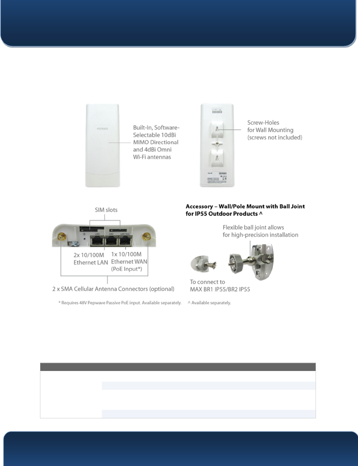
4.13 MAX BR1/2 IP55
4.13.1 Panel Appearance
4.13.2 LED Indicators
The statuses indicated by the front panel LEDs are as follows:
Status Indicators
Status
OFF System initializing
Red Booting up or busy
Blinking
red Boot up error
Green Ready

Pepwave MAX and Surf User Manual
http://www.pepwave.com 30 Copyright @ 2016 Pepwave
Wi-Fi Indicators
Wi-Fi
OFF Disabled Intermittent
Blinking slowly Connecting to wireless network(s)
Blinking Connected to wireless network(s) with traffic
ON Connected to wireless network(s) without traffic
Cellular Indicators
Cellular OFF Disabled or no SIM card inserted
ON Connecting or connected to network(s)
LAN and Ethernet WAN Ports
Green LED ON 100 Mbps
OFF 10 Mbps
Orange LED
ON Port is connected without traffic
Blinking Data is transferring
OFF Port is not connected
Port Type Auto MDI/MDI-X ports
Pepwave MAX and Surf User Manual
http://www.pepwave.com 31 Copyright @ 2016 Pepwave
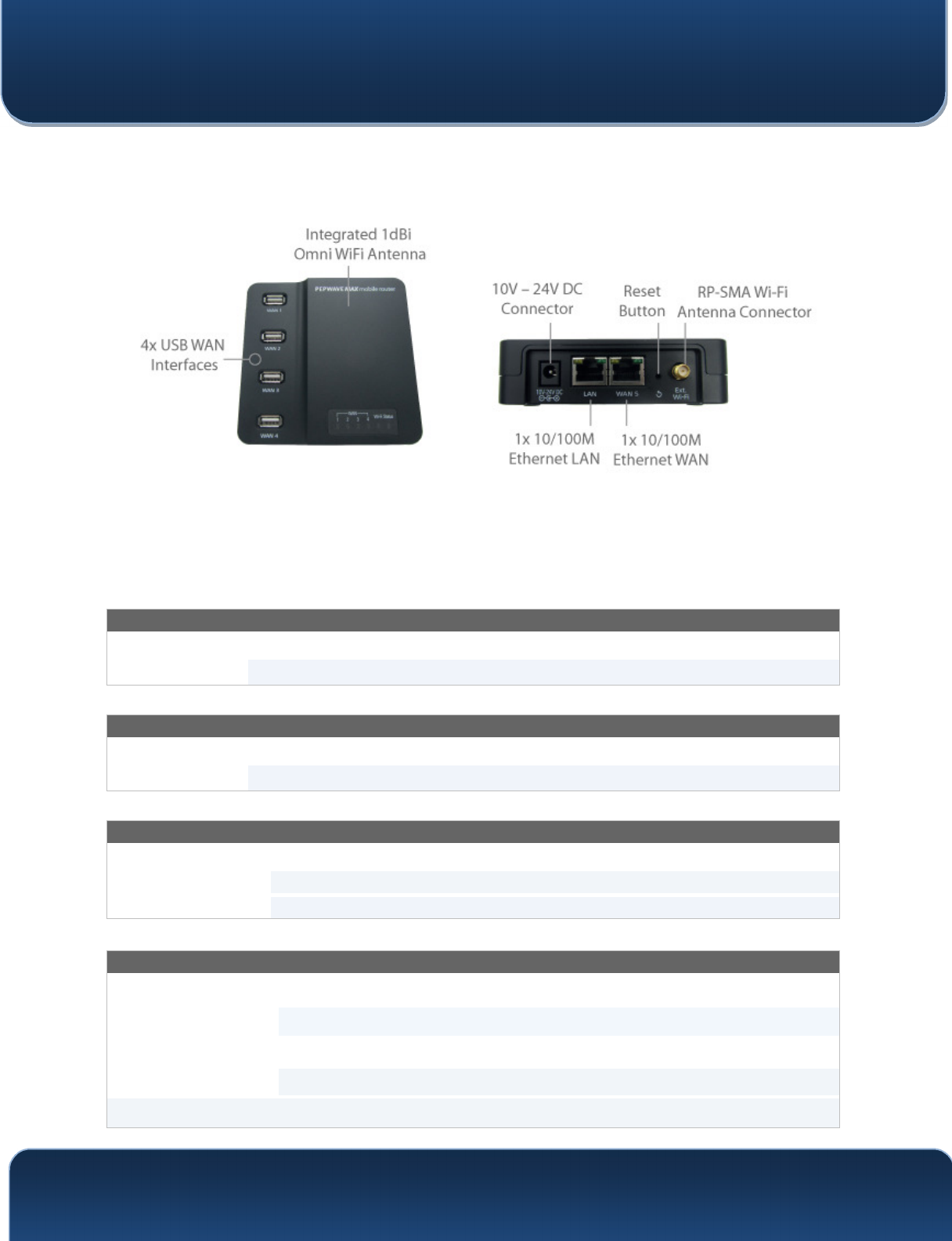
4.14 MAX On-The-Go
4.14.1 Panel Appearance
4.14.2 LED Indicators
The statuses indicated by the front panel LEDs are as follows:
Cellular Indicators
WAN OFF Modem is not attached to the port
Green Modem is attached to the port
Wi-Fi Indicators
Wi-Fi OFF Disconnected from AP
Green Connected to AP
Status Indicators
Status
OFF System initializing
Red Booting up or busy
Green Ready
LAN and Ethernet WAN Ports
Green LED ON 100 Mbps
OFF 10 Mbps
Orange LED ON Port is connected without traffic
Blinking Data is transferring
Port Type Auto MDI/MDI-X ports
Pepwave MAX and Surf User Manual
http://www.pepwave.com 32 Copyright @ 2016 Pepwave
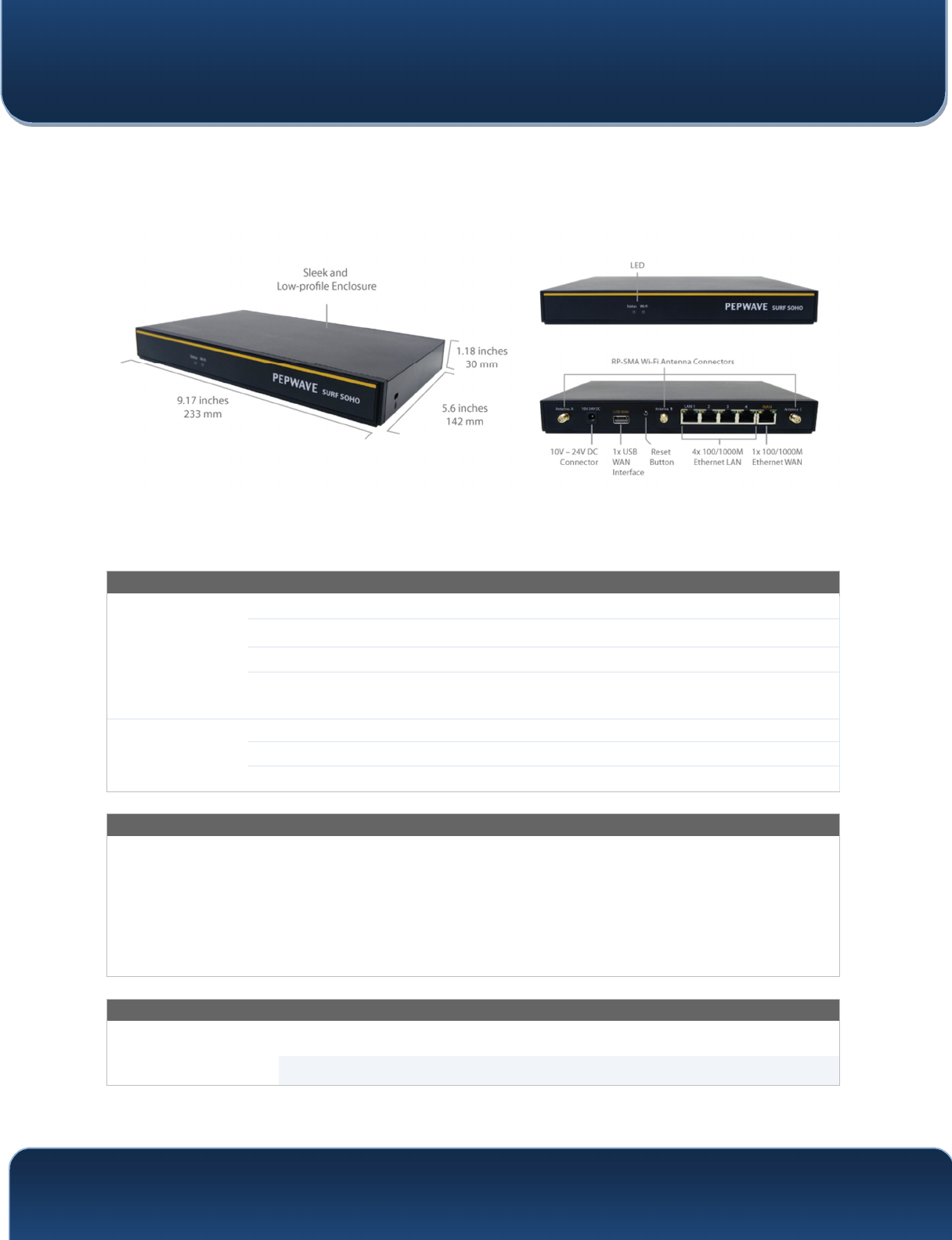
4.15 Surf SOHO
4.15.1 Panel Appearance
4.15.2 LED Indicators
The statuses indicated by the front panel LEDs are as follows:
Wi-Fi and Status Indicators
Wi-Fi
OFF Disabled Intermittent
Blinking Enabled but no client connected
ON Client(s) connected to wireless network
Continuous
blinking Transferring data to wireless network
Status
OFF System initializing
Red Booting up or busy
Green Ready state
LAN and Ethernet WAN Ports
Green LED ON 100/1000 Mbps
Orange LED
Blinking Data is transferring
OFF No data is being transferred or port is not
connected
Port type Auto MDI/MDI-X ports
Wi-Fi Signal
Off No connection
Signal strength Wi-Fi signal strength (low, medium, and high)
Pepwave MAX and Surf User Manual
http://www.pepwave.com 33 Copyright @ 2016 Pepwave
5 Advanced Feature Summary
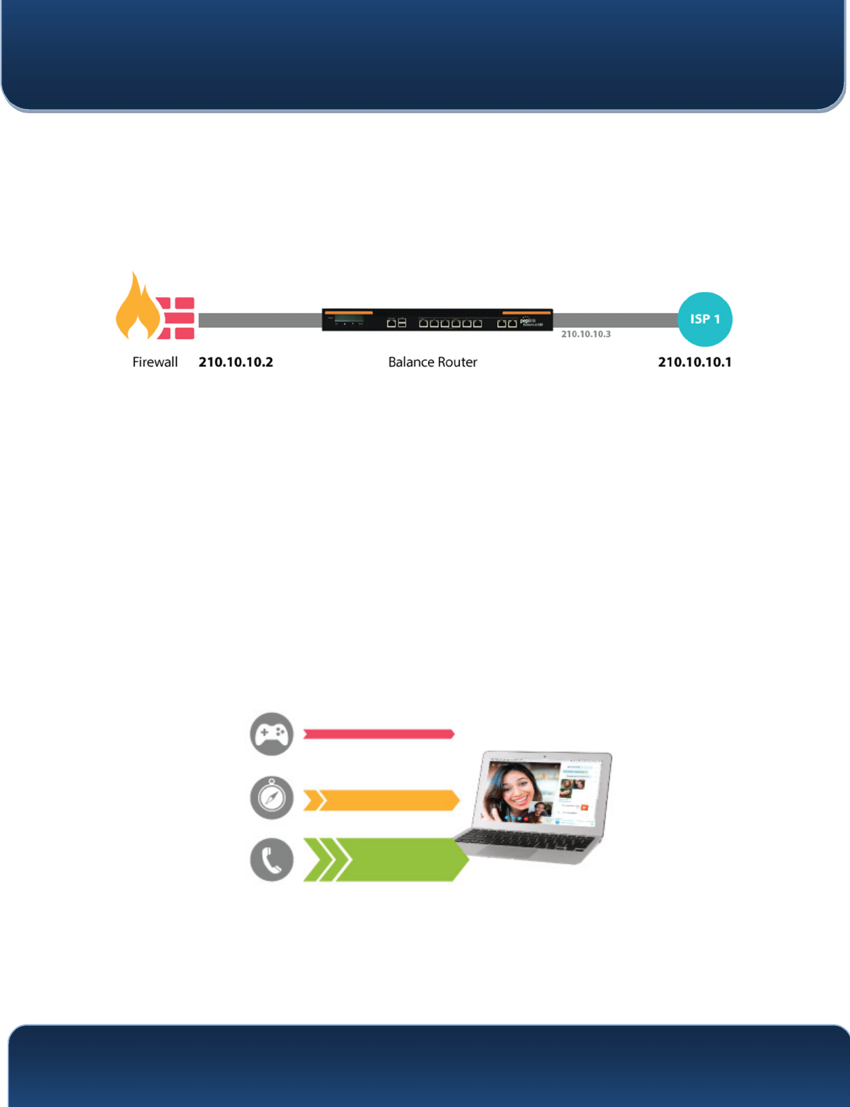
5.1 Drop-in Mode and LAN Bypass: Transparent Deployment
As your organization grows, it needs more bandwidth. But modifying your network would require
effort better spent elsewhere. In Drop-in Mode, you can conveniently install your Peplink router
without making any changes to your network. And if the Peplink router loses power for any reason,
LAN Bypass will safely and automatically bypass the Peplink router to resume your original network
connection.
Compatible with: MAX 700, MAX HD2 (All variants), HD4 (All Variants)
5.2 QoS: Clearer VoIP
VoIP and videoconferencing are highly sensitive to latency. With QoS, Peplink routers can detect
VoIP traffic and assign it the highest priority, giving you crystal-clear calls.
Pepwave MAX and Surf User Manual
http://www.pepwave.com 34 Copyright @ 2016 Pepwave
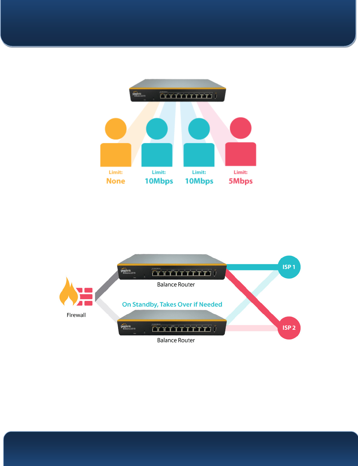
5.3 Per-User Bandwidth Control
With per-user bandwidth control, you can define bandwidth control policies for up to 3 groups of
users to prevent network congestion. Define groups by IP address and subnet, and set bandwidth
limits for every user in the group.
5.4 High Availability via VRRP
When your organization has a corporate requirement demanding the highest availability with no
single point of failure, you can deploy two Peplink routers in High Availability mode. With High
Availability mode, the second device will take over when needed.
Compatible with: MAX 700, MAX HD2 (All variants), HD4 (All Variants)
Pepwave MAX and Surf User Manual
http://www.pepwave.com 35 Copyright @ 2016 Pepwave
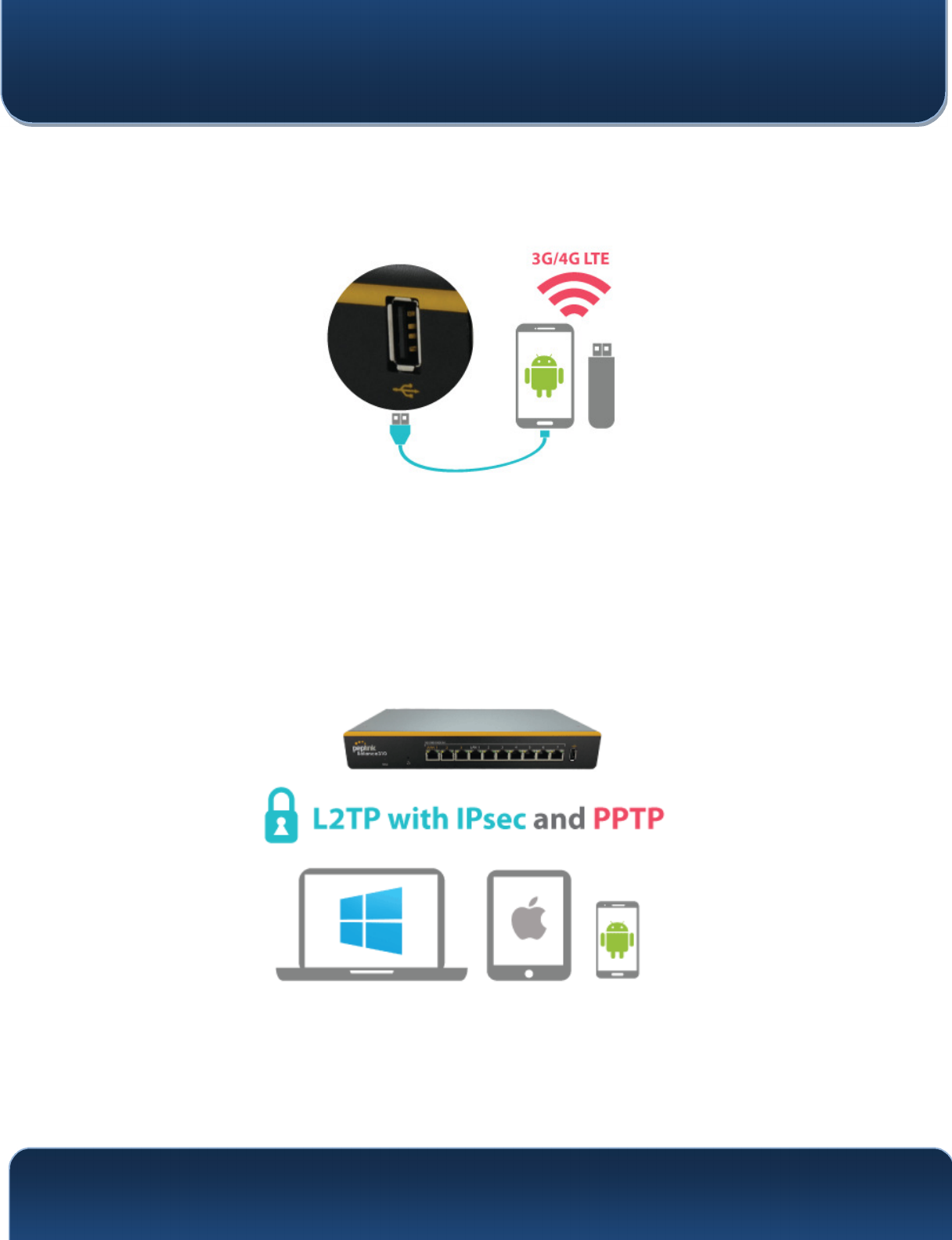
5.5 USB Modem and Android Tethering
For increased WAN diversity, plug in a USB LTE modem as backup. Peplink routers are
compatible with over 200 modem types. You can also tether to smartphones running Android
4.1.X and above.
Compatible with: MAX 700, HD2 (all variants except IP67), HD4 (All variants)
5.6 Built-In Remote User VPN Support
Use L2TP with IPsec to safely and conveniently connect remote clients to your private network.
L2TP with IPsec is supported by most devices, but legacy devices can also connect using PPTP.
Click here for full instructions on setting up L2TP with IPsec.

Pepwave MAX and Surf User Manual
http://www.pepwave.com 36 Copyright @ 2016 Pepwave
5.7 SIM-card USSD support
Cellular-enabled routers can now use USSD to check their SIM card’s balance, process pre-paid
cards, and configure carrier-specific services.Click here for full instructions on using USSD.

Pepwave MAX and Surf User Manual
http://www.pepwave.com 37 Copyright @ 2016 Pepwave
6 Installation
The following section details connecting Pepwave routers to your network.
6.1 Preparation
Before installing your Pepwave router, please prepare the following as appropriate for
your installation:
At least one Internet/WAN access account and/or Wi-Fi access information
Depending on network connection type(s), one or more of the following:
Ethernet WAN: A 10/100/1000BaseT UTP cable with RJ45 connector
USB: A USB modem
Embedded modem: A SIM card for GSM/HSPA service
Wi-Fi WAN: Wi-Fi antennas
PC Card/Express Card WAN: A PC Card/ExpressCard for the
corresponding card slot
A computer installed with the TCP/IP network protocol and a supported web
browser. Supported browsers include Microsoft Internet Explorer 8.0 or above,
Mozilla Firefox 10.0 or above, Apple Safari 5.1 or above, and Google Chrome 18
or above.
Pepwave MAX and Surf User Manual
http://www.pepwave.com 38 Copyright @ 2016 Pepwave
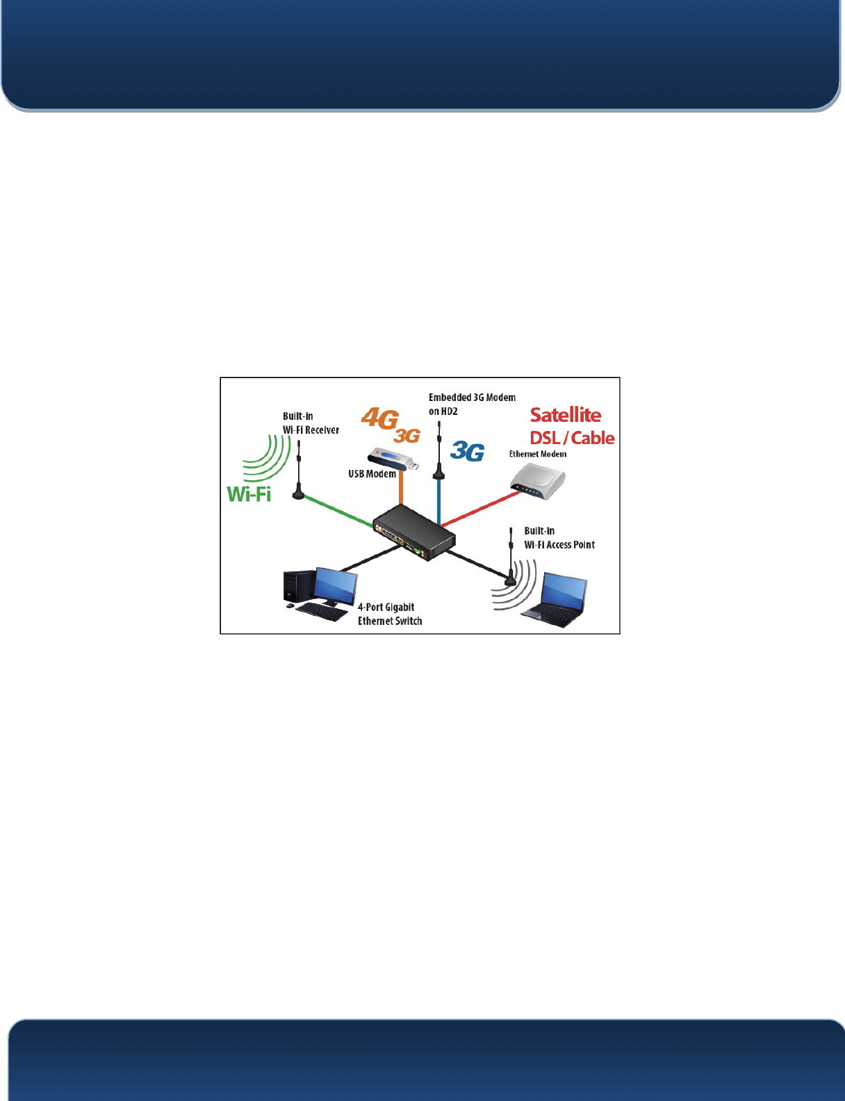
6.2 Constructing the Network
At a high level, construct the network according to the following steps:
1. With an Ethernet cable, connect a computer to one of the LAN ports on the
Pepwave router. Repeat with different cables for up to 4 computers to be
connected.
2. With another Ethernet cable or a USB modem/Wi-Fi antenna/PC
Card/Express Card, connect to one of the WAN ports on the Pepwave
router. Repeat the same procedure for other WAN ports.
3. Connect the power adapter to the power connector on the rear panel of the
Pepwave router, and then plug it into a power outlet.
The following figure schematically illustrates the resulting configuration:

Pepwave MAX and Surf User Manual
http://www.pepwave.com 39 Copyright @ 2016 Pepwave
6.3 Configuring the Network Environment
To ensure that the Pepwave router works properly in the LAN environment and can
access the Internet via WAN connections, please refer to the following setup
procedures:
LAN configuration
For basic configuration, refer to Section 8, Connecting to the Web Admin
Interface.
For advanced configuration, go to Section 9, Configuring the LAN Interface(s).
WAN configuration
For basic configuration, refer to Section 8, Connecting to the Web Admin
Interface.
For advanced configuration, go to Section 9.2, Captive Portal.
Pepwave MAX and Surf User Manual
http://www.pepwave.com 40 Copyright @ 2016 Pepwave
7 Mounting the Unit
7.1 Wall Mount
The Pepwave MAX 700/HD2/On-The-Go can be wall mounted using screws. After
adding the screw on the wall, slide the MAX in the screw hole socket as indicated
below. Recommeneded screw specification: M3.5 x 20mm, head diameter 6mm, head
thickness 2.4mm.
The Pepwave MAX BR1 requires four screws for wall mounting.
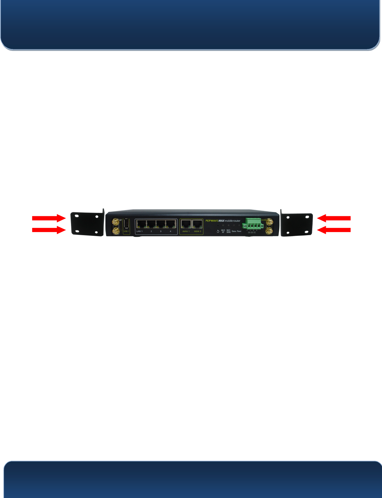
7.2 Car Mount
The Pepwave MAX700/HD2 can be mounted in a vehicle using the included mounting
brackets. Place the mounting brackets by the two sides and screw them onto the
device.
7.3 IP67 Installation Guide
Installation instructions for IP67 devices can be found here:
http://download.peplink.com/manual/IP67_Installation_Guide.pdf
Pepwave MAX and Surf User Manual
http://www.pepwave.com 41 Copyright @ 2016 Pepwave
8 Connecting to the Web Admin Interface
1. Start a web browser on a computer that is connected with the Pepwave router
through the LAN.
2. To connect to the router’s web admin interface, enter the following LAN IP address
in the address field of the web browser:
http://192.168.50.1
(This is the default LAN IP address for Pepwave routers.)
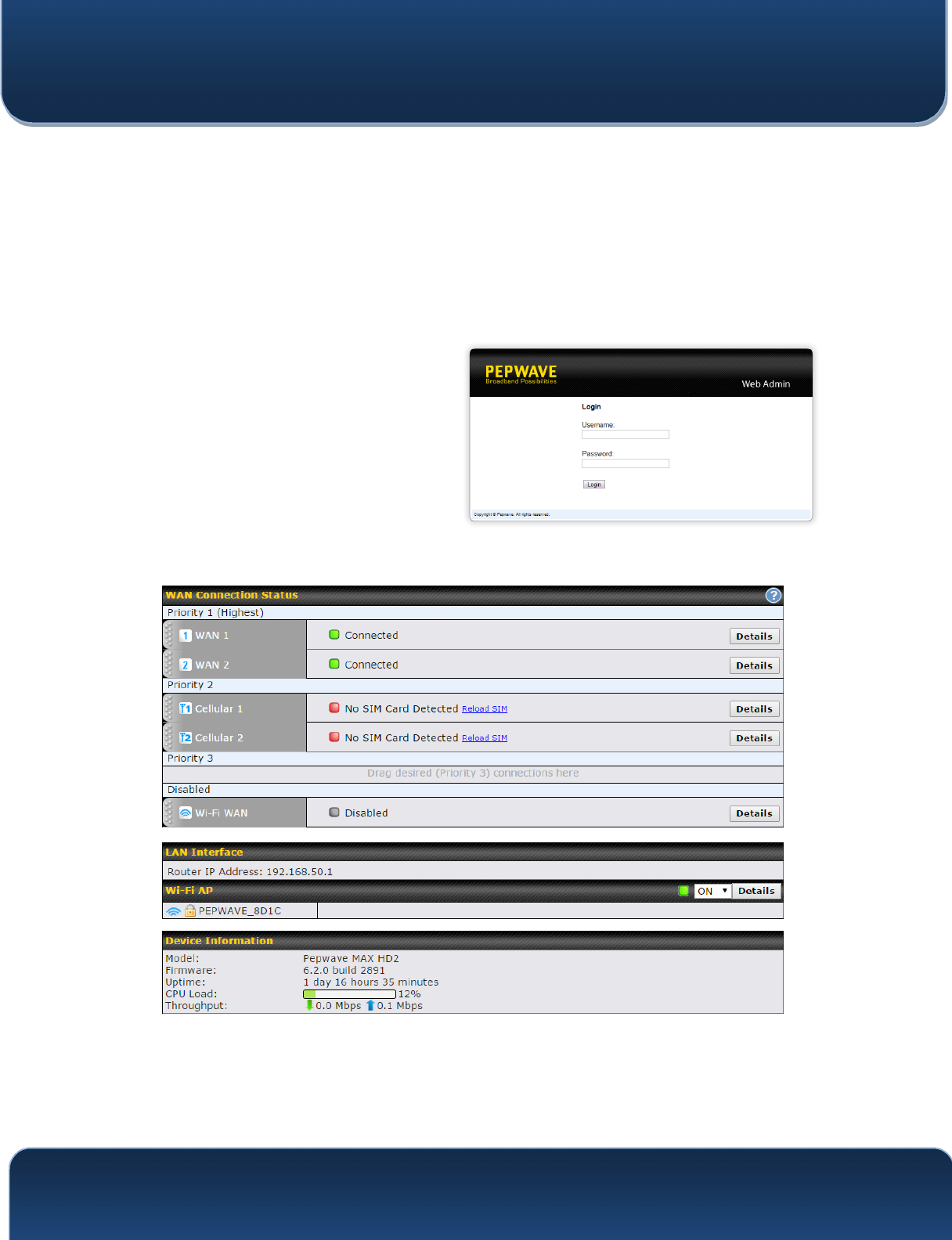
3. Enter the following to access the web
admin interface.
Username: admin
Password: admin
(This is the default username and
password for Pepwave routers. The
admin and read-only user passwords
can be changed at System>Admin
Security.)
4. After successful login, the Dashboard will be displayed.
The Dashboard shows current WAN, LAN, and Wi-Fi AP statuses. Here, you can
change WAN connection priority and switch on/off the Wi-Fi AP. For further information
on setting up these connections, please refer to Sections 8 and 9.

Pepwave MAX and Surf User Manual
http://www.pepwave.com 42 Copyright @ 2016 Pepwave
Device Information displays details about the device, including model name, firmware
version, and uptime. For further information, please refer to Section 22.
Important Note
Configuration changes (e.g. WAN, LAN, admin settings, etc.) will take effect only after clicking the Save button at
the bottom of each page. The Apply Changes button causes the changes to be saved and applied.
Pepwave MAX and Surf User Manual
http://www.pepwave.com 43 Copyright @ 2016 Pepwave
9 Configuring the LAN Interface(s)
9.1 Basic Settings
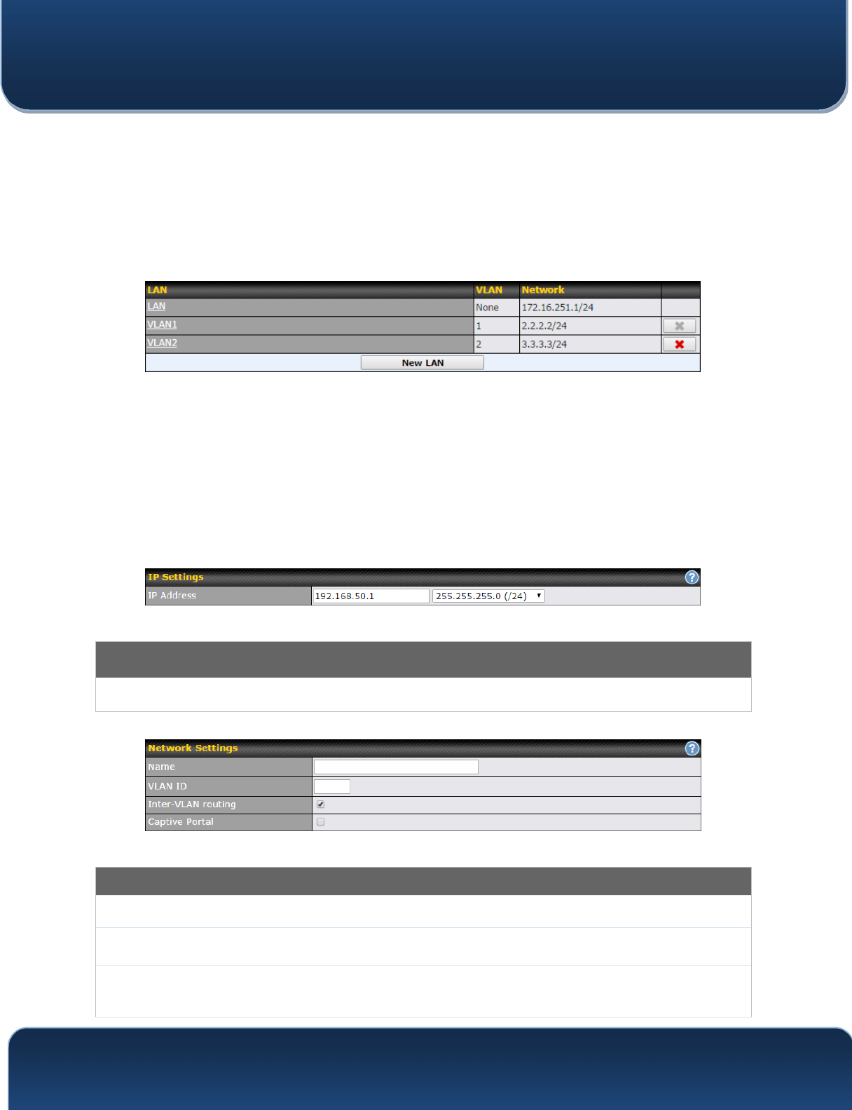
LAN interface settings are located at Network>LAN>Basic Settings. Navigating to that
page will result in the following dashboard:
This represents the LAN interfaces that are active on your router (including VLAN). A
grey “X” means that the VLAN is used in other settings and cannot be deleted. You can
find which settings are using the VLAN by hovering over the grey “X”.
Alternatively, a red “X” means that there are no settings using the VLAN. You can delete
that VLAN by clicking the red “X”
Clicking any of the existing LAN interfaces (or creating a new one) will result in the
following
IP Settings
IP Address
The IP address and subnet mask of the
Pepwave router on the LAN.
Network Settings
Name
Enter a name for the LAN.
VLAN ID
Enter a number for your VLAN.
Inter-VLAN
routing
Check this box to enable routing between virtual LANs.
Pepwave MAX and Surf User Manual
http://www.pepwave.com 44 Copyright @ 2016 Pepwave
Captive Portal
Check this box to turn on captive portals.
Pepwave MAX and Surf User Manual
http://www.pepwave.com 45 Copyright @ 2016 Pepwave
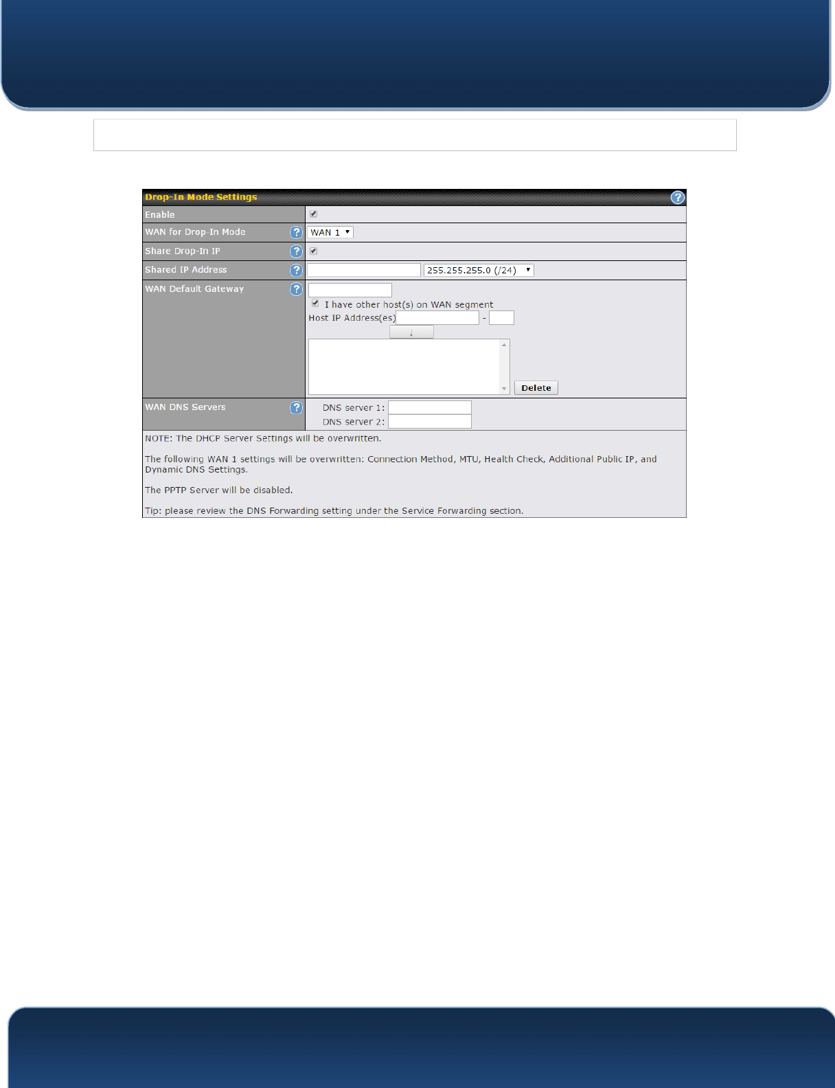
Drop-in Mode Settings
Enable
Drop-in mode eases the installation of Peplink routers on a live network between the
existing firewall and router, such that no configuration changes are required on existing
equipment. Check the box to enable the drop-in mode feature, if available on your model.
WAN for Drop-
In Mode
Select the WAN port to be used for drop-in mode. If WAN 1 with LAN Bypass is selected,
the high availability feature will be disabled automatically.
Share Drop-In
IP
A
When this option is enabled, the passthrough IP address will be used to connect to WAN
hosts (email notification, remote syslog, etc.). The Pepwave router will listen for this IP
address when WAN hosts access services provided by the Pepwave router (web admin
access from the WAN, DNS server requests, etc.).
To connect to hosts on the LAN (email notification, remote syslog, etc.), the default gateway
address will be used. The Pepwave router will listen for this IP address when LAN hosts
access services provided by the Pepwave router (web admin access from the WAN, DNS
proxy, etc.).
Shared IP
Address
A
Access to this IP address will be passed through to the LAN port if this device is not serving
the service being accessed. The shared IP address will be used in connecting to hosts on
the WAN (email notification, remote syslog, etc.) The device will also listen on the IP
address when hosts on the WAN access services served on this device (web admin access
from the WAN, DNS server, etc.)
WAN Default
Gateway
Enter the WAN router's IP address in this field. If there are more hosts in addition to the
router on the WAN segment, check the I have other host(s) on WAN segment box and
enter the IP address of the hosts that need to access LAN devices or be accessed by
others.
WAN DNS
Servers
Enter the selected WAN's corresponding DNS server IP addresses.
A
- Advanced feature, please click the button on the top right-hand corner to activate.
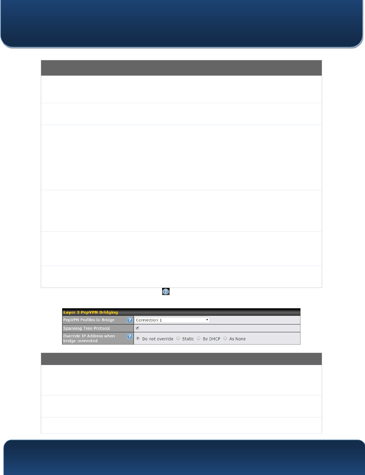
Layer 2 PepVPN Bridging
PepVPN
Profiles to
Bridge
The remote network of the selected PepVPN profiles will be bridged with this local LAN,
creating a Layer 2 PepVPN, they will be connected and operate like a single LAN, and any
broadcast or multicast packets will be sent over the VPN.
Spanning Tree
Protocol
Click the box will enable STP for this layer 2 profile bridge.
Override IP
Select "Do not override" if the LAN IP address and local DHCP server should remain
unchanged after the Layer 2 PepVPN is up.
Pepwave MAX and Surf User Manual
http://www.pepwave.com 46 Copyright @ 2016 Pepwave
Address when
bridge
connected
If you choose to override IP address when the VPN is connected, the device will not act as a
router, and most Layer 3 routing functions will cease to work.
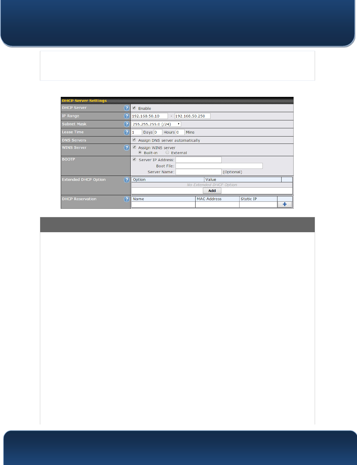
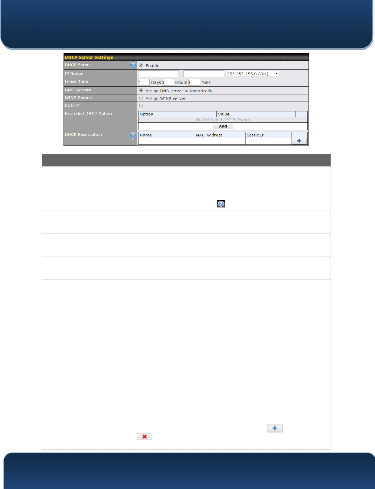
DHCP Server Settings
DHCP Server
When this setting is enabled, the DHCP server automatically assigns an IP address to
each computer that is connected via LAN and configured to obtain an IP address via
DHCP. The Pepwave router’s DHCP server can prevent IP address collision on the LAN.
IP Range &
Subnet Mask
These settings allocate a range of IP addresses that will be assigned to LAN computers by
the Pepwave router’s DHCP server.
Lease Time
This setting specifies the length of time throughout which an IP address of a DHCP client
remains valid. Upon expiration of the lease time, the assigned IP address will no longer be
valid and renewal of the IP address assignment will be required.
DNS Servers
This option allows you to input the DNS server addresses to be offered to DHCP clients. If
Assign DNS server automatically is selected, the Pepwave router’s built-in DNS server
address (i.e., LAN IP address) will be offered.
WINS Server
This option allows you to optionally specify a Windows Internet Name Service (WINS)
server. You may choose to use the built-in WINS server or external WINS servers.
When this unit is connected using SpeedFusion
TM
, other VPN peers can share this unit's
built-in WINS server by entering this unit's LAN IP address in their DHCP WINS Server
setting. Afterward, all PC clients in the VPN can resolve the NetBIOS names of other
clients in remote peers. If you have enabled this option, a list of WINS clients will be
displayed at Status>WINS Clients.
BOOTP
Check this box to enable BOOTP on older networks that still require it.
Extended
DHCP Option
In addition to standard DHCP options (e.g., DNS server address, gateway address, subnet
mask), you can specify the value of additional extended DHCP options, as defined in RFC
2132. With these extended options enabled, you can pass additional configuration
information to LAN hosts.
To define an extended DHCP option, click the Add button, choose the option to define and
Pepwave MAX and Surf User Manual
http://www.pepwave.com 47 Copyright @ 2016 Pepwave
enter its value. For values that are in IP address list format, you can enter one IP address
per line in the provided text area input control. Each option can be defined once only.
DHCP
Reservation
This setting reserves the assignment of fixed IP addresses for a list of computers on the
LAN. The computers to be assigned fixed IP addresses on the LAN are identified by their
MAC addresses. The fixed IP address assignment is displayed as a cross-reference list
between the computers’ names, MAC addresses, and fixed IP addresses.
Name (an optional field) allows you to specify a name to represent the device. MAC
addresses should be in the format of 00:AA:BB:CC:DD:EE. Press to create a new
record. Press to remove a record. Reserved client information can be imported from
the Client List, located at Status>Client List. For more details, please refer to Section
22.3.
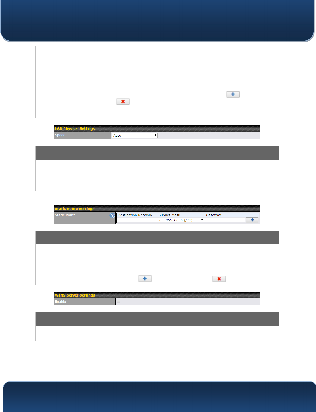
LAN Physical Settings
Speed
This is the port speed of the LAN interface. It should be set to the same speed as the
connected device to avoid port negotiation problems. When a static speed is set, you may
choose whether to advertise its speed to the peer device. Auto is selected by default. You
can choose not to advertise the port speed if the port has difficulty negotiating with the
peer device.
Static Route Settings
Static Route
This table is for defining static routing rules for the LAN segment. A static route consists of
the network address, subnet mask, and gateway address. The address and subnet mask
values are in w.x.y.z format.
The local LAN subnet and subnets behind the LAN will be advertised to the VPN. Remote
routes sent over the VPN will also be accepted. Any VPN member will be able to route to
the local subnets. Press to create a new route. Press to remove a route.
WINS Server Settings
Enable
Check the box to enable the WINS server. A list of WINS clients will be displayed at
Status>WINS Clients.
Pepwave MAX and Surf User Manual
http://www.pepwave.com 48 Copyright @ 2016 Pepwave
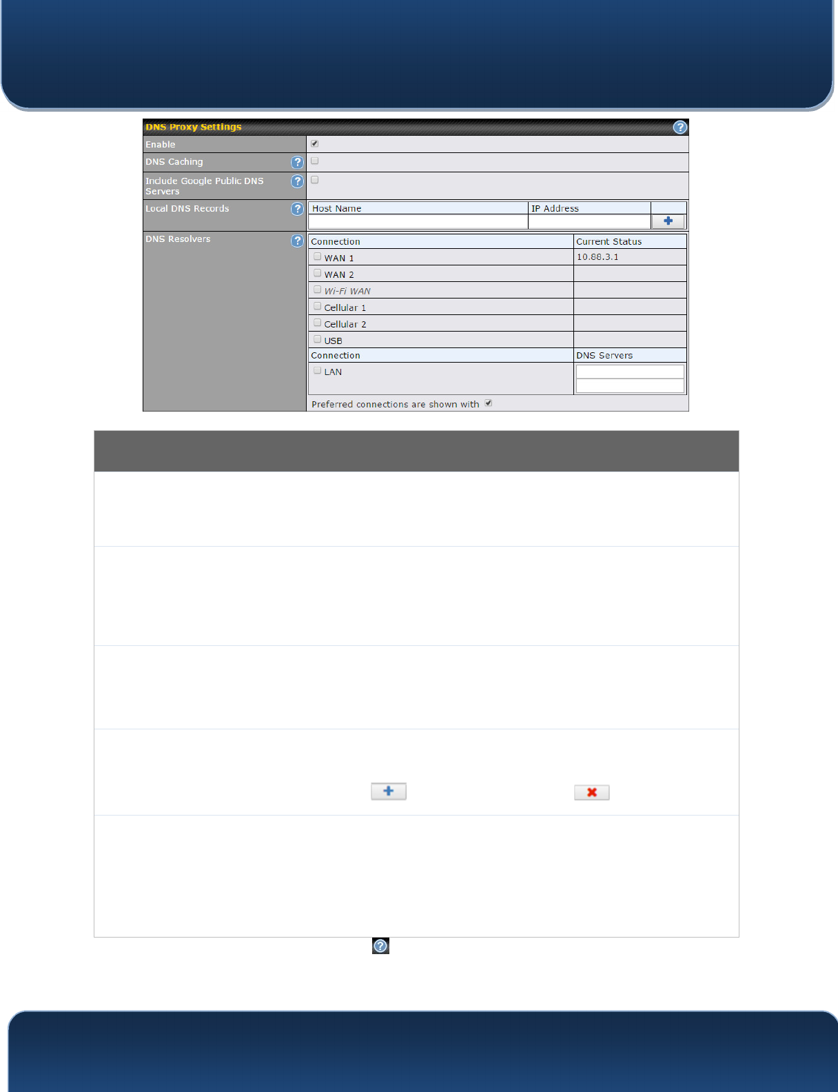
DNS Proxy Settings
Enable
To enable the DNS proxy feature, check this box, and then set up the feature at
Network>LAN>DNS Proxy Settings. A DNS proxy server can be enabled to
serve DNS requests originating from LAN/PPTP/SpeedFusion
TM
peers. Requests
are forwarded to the DNS servers/resolvers defined for each WAN connection.
DNS Caching
This field is to enable DNS caching on the built-in DNS proxy server. When the
option is enabled, queried DNS replies will be cached until the records’ TTL has
been reached. This feature can help improve DNS lookup time. However, it
cannot return the most up-to-date result for those frequently updated DNS
records. By default, DNS Caching is disabled.
Include Google Public
DNS Servers
When this option is enabled, the DNS proxy server will also forward DNS
requests to Google's Public DNS Servers, in addition to the DNS servers defined
in each WAN. This could increase the DNS service's availability. This setting is
disabled by default.
Local DNS Records
This table is for defining custom local DNS records. A static local DNS record
consists of a host name and IP address. When looking up the host name from the
LAN to LAN IP of the Pepwave router, the corresponding IP address will be
returned. Press to create a new record. Press to remove a record.
DNS Resolvers
A
Check the box to enable the WINS server. A list of WINS clients will be displayed
at Network>LAN>DNS Proxy Settings>DNS Resolvers. This field specifies
which DNS resolvers will receive forwarded DNS requests. If no WAN/VPN/LAN
DNS resolver is selected, all of the WAN’s DNS resolvers will be selected.
If a SpeedFusion
TM
peer is selected, you may enter the VPN peer’s DNS resolver
IP address(es). Queries will be forwarded to the selected connections’ resolvers. If
all of the selected connections are down, queries will be forwarded to all resolvers
on healthy WAN connections.
A
- Advanced feature, please click the button on the top right hand corner to activate.
Finally, if needed, configure Bonjour forwarding, Apple’s zero configuration networking
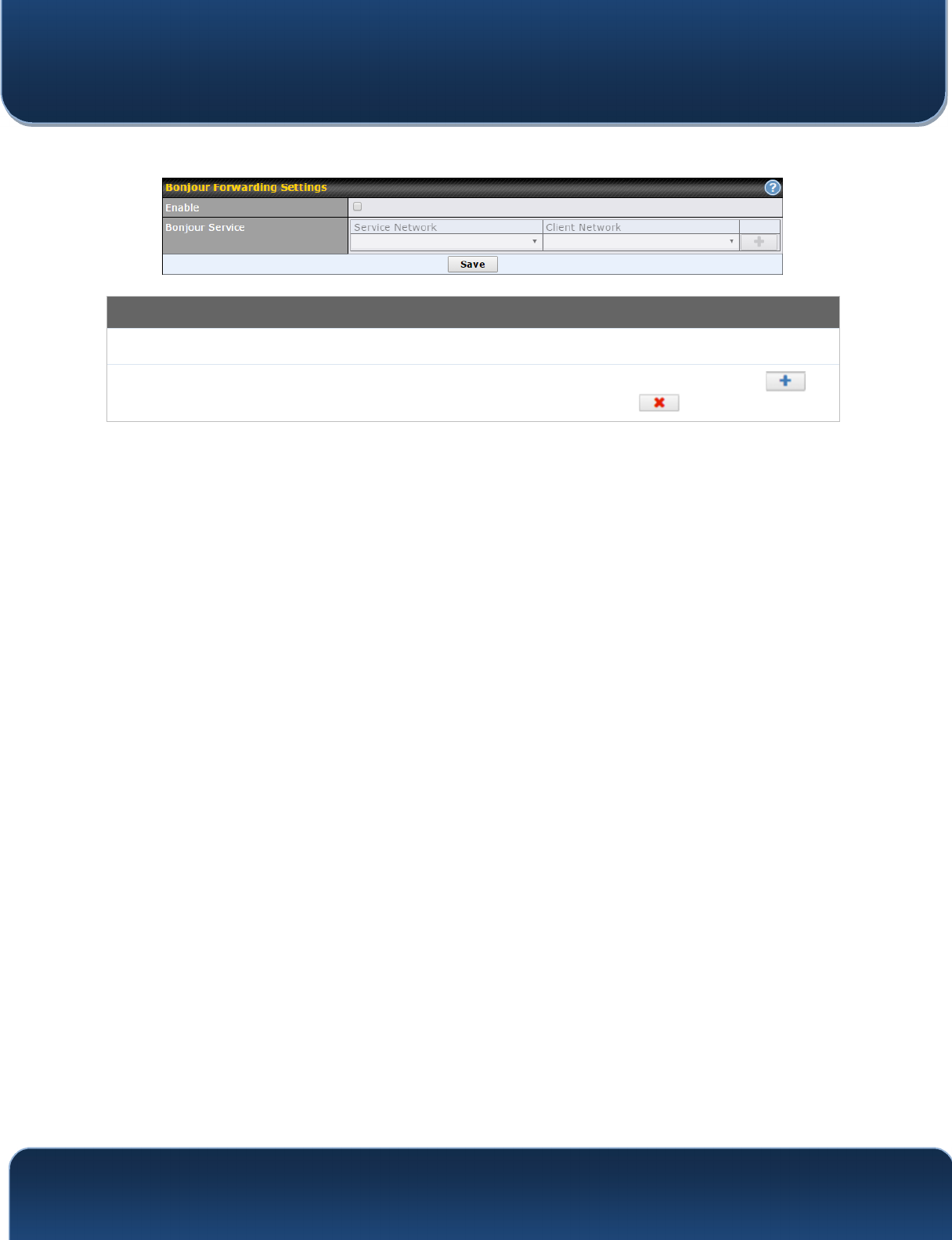
Pepwave MAX and Surf User Manual
http://www.pepwave.com 49 Copyright @ 2016 Pepwave
protocol. Once VLAN configuration is complete, click Save to store your changes.
Bonjour Forwarding Settings
Enable
Check this box to turn on Bonjour forwarding.
Bonjour
Service
Choose Service and Client networks from the drop-down menus, and then click to
add the networks. To delete an existing Bonjour listing, click .
Pepwave MAX and Surf User Manual
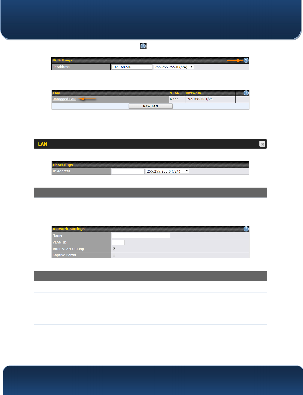
http://www.pepwave.com 50 Copyright @ 2016 Pepwave
To enable VLAN configuration, click the button in the IP Settings section.
To add a new LAN, click the New LAN button. To change LAN settings, click the name
of the LAN to change under the LAN heading.
The following settings are displayed when creating a new LAN or editing an existing
LAN.
IP Settings
IP Address &
Subnet Mask
Enter the Pepwave router’s IP address and subnet mask values to be used on the LAN.
Network Settings
Name
Enter a name for the LAN.
VLAN ID
Enter a number for your VLAN.
Inter-VLAN
routing
Check this box to enable routing between virtual LANs.
Captive Portal
Check this box to turn on captive portals.
Pepwave MAX and Surf User Manual
http://www.pepwave.com 51 Copyright @ 2016 Pepwave
DHCP Server Settings
DHCP Server
When this setting is enabled, the Pepwave router’s DHCP server automatically assigns an
IP address to each computer that is connected via LAN and configured to obtain an IP
address via DHCP. The Pepwave router’s DHCP server can prevent IP address collisions
on the LAN.
To enable DHCP bridge relay, please click the icon on this menu item.
IP Range &
Subnet Mask
These settings allocate a range of IP address that will be assigned to LAN computers by the
Pepwave router’s DHCP server.
Lease Time
This setting specifies the length of time throughout which an IP address of a DHCP client
remains valid. Upon expiration of Lease Time, the assigned IP address will no longer be
valid and the IP address assignment must be renewed.
DNS Servers
This option allows you to input the DNS server addresses to be offered to DHCP clients. If
Assign DNS server automatically is selected, the Pepwave router’s built-in DNS server
address (i.e., LAN IP address) will be offered.
WINS Servers
This option allows you to specify the Windows Internet Name Service (WINS) server. You
may choose to use the built-in WINS server or external WINS servers. When this unit is
connected using SpeedFusion
TM
, other VPN peers can share this unit's built-in WINS server
by entering this unit's LAN IP address in their DHCP WINS Servers setting. Therefore, all
PC clients in the VPN can resolve the NetBIOS names of other clients in remote peers. If
you have enabled this option, a list of WINS clients will be displayed at Status>WINS
Clients.
BOOTP
Check this box to enable BOOTP on older networks that still require it.
Extended
DHCP Option
In addition to standard DHCP options (e.g. DNS server address, gateway address, subnet
mask), you can specify the value of additional extended DHCP options, as defined in RFC
2132. With these extended options enabled, you can pass additional configuration
information to LAN hosts. To define an extended DHCP option, click the Add button, choose
the option to define, and then enter its value. For values that are in IP address list format,
you can enter one IP address per line in the provided text area input control. Each option
can be defined once only.
DHCP
Reservation
This setting reserves the assignment of fixed IP addresses for a list of computers on the
LAN. The computers to be assigned fixed IP addresses on the LAN are identified by their
MAC addresses. The fixed IP address assignment is displayed as a cross-reference list
between the computers’ names, MAC addresses, and fixed IP addresses.
Name (an optional field) allows you to specify a name to represent the device. MAC
addresses should be in the format of 00:AA:BB:CC:DD:EE. Press to create a new
record. Press to remove a record. Reserved clients information can be imported from
the Client List, located at Status>Client List. For more details, please refer to Section
Pepwave MAX and Surf User Manual
http://www.pepwave.com 52 Copyright @ 2016 Pepwave
22.3
.
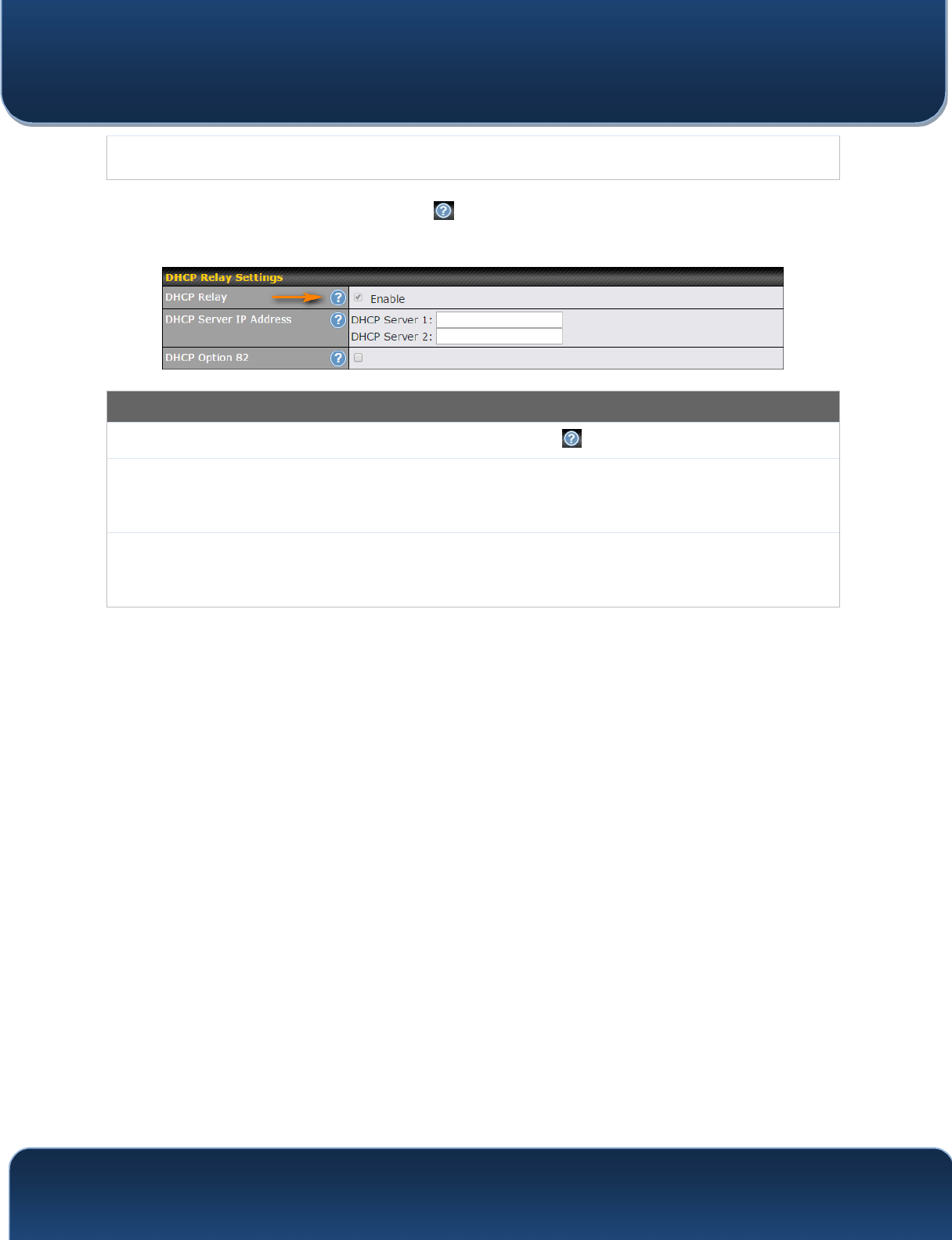
To configure DHCP relay, first click the button found next to the DHCP Server option
to display the settings.
DHCP Relay Settings
Enable
Check this box to turn on DHCP relay. Click the icon to disable DHCP relay.
DHCP Server IP
Address
Enter the IP addresses of one or two DHCP servers in the provided fields. The DHCP
servers entered here will receive relayed DHCP requests from the LAN. For active-passive
DHCP server configurations, enter active and passive DHCP server relay IP addresses in
DHCP Server 1 and DHCP Server 2.
DHCP Option
82
DCHP Option 82 includes device information as relay agent for the attached client when
forwarding DHCP requests from client to server. This option also embeds the device’s MAC
address and network name in circuit and remote IDs. Check this box to enable DHCP
Option 82.
Once DHCP is set up, configure LAN Physical Settings, Static Route Settings, WINS
Server Settings, and DNS Proxy Settings as noted above.
Pepwave MAX and Surf User Manual
http://www.pepwave.com 53 Copyright @ 2016 Pepwave
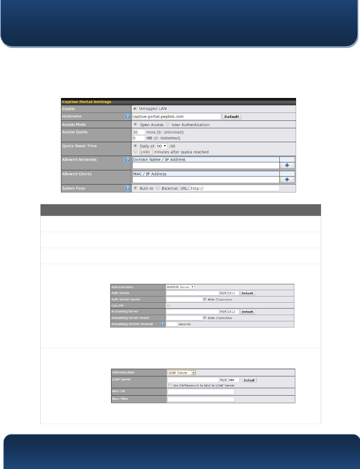
9.2 Captive Portal
The captive portal serves as gateway that clients have to pass if they wish to access the
internet using your router. To configure, navigate to Network>LAN>Captive Portal.
Captive Portal Settings
Enable
Check Enable and then, optionally, select the LANs/VLANs that will use the captive
portal.
Hostname
To customize the portal’s form submission and redirection URL, enter a new URL in this
field. To reset the URL to factory settings, click Default.
Access Mode
Click Open Access to allow clients to freely access your router. Click User
Authentication to force your clients to authenticate before accessing your router.
RADIUS Server
This authenticates your clients through a RADIUS server. After selecting this option, you
will see the following fields:
Fill in the necessary information to complete your connection to the server and enable
authentication.
LDAP Server
This authenticates your clients through a LDAP server. Upon selecting this option, you
will see the following fields:
Fill in the necessary information to complete your connection to the server and enable
authentication.
Pepwave MAX and Surf User Manual
http://www.pepwave.com 54 Copyright @ 2016 Pepwave
Access
Quota
Set a time and data cap to each user’s Internet usage.
Quota Reset
Time
This menu determines how your usage quota resets. Setting it to Daily will reset it at a
specified time every day. Setting a number of minutes after quota reached establish a
timer for each user that begins after the quota has been reached.
Allowed
Networks
To whitelist a network, enter the domain name / IP address here and click . To
delete an existing network from the list of allowed networks, click the button next
to the listing.
Splash Page
Here, you can choose between using the Pepwave router’s built-in captive portal and
redirecting clients to a URL you define.
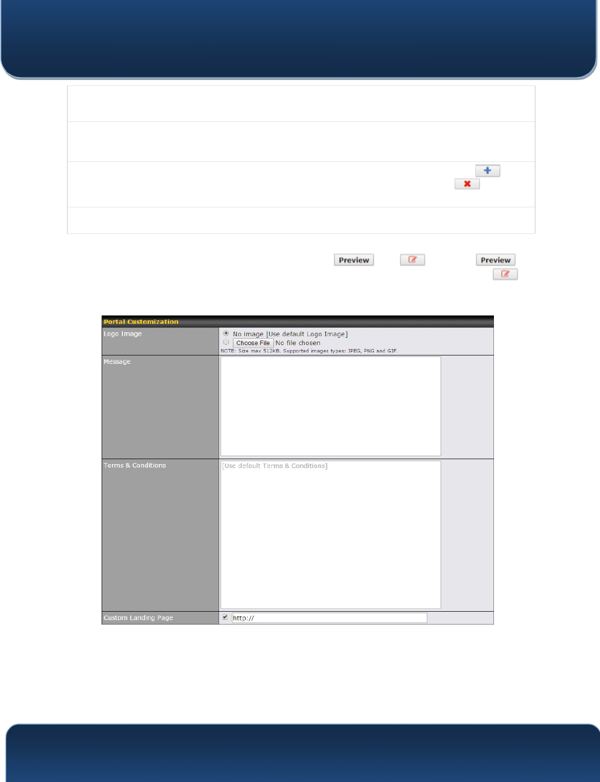
The Portal Customization menu has two options: and . Clicking
displays a pop-up previewing the captive portal that your clients will see. Clicking
displays the following menu: