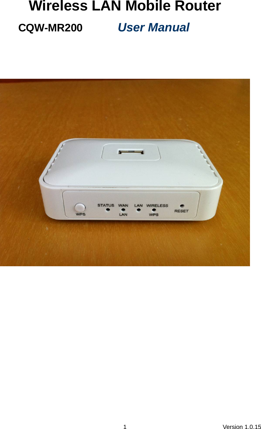
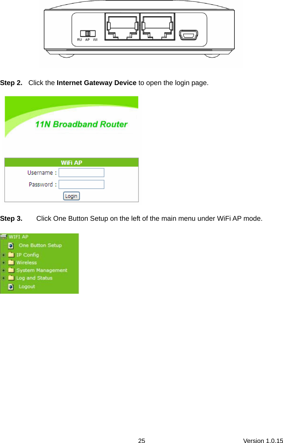
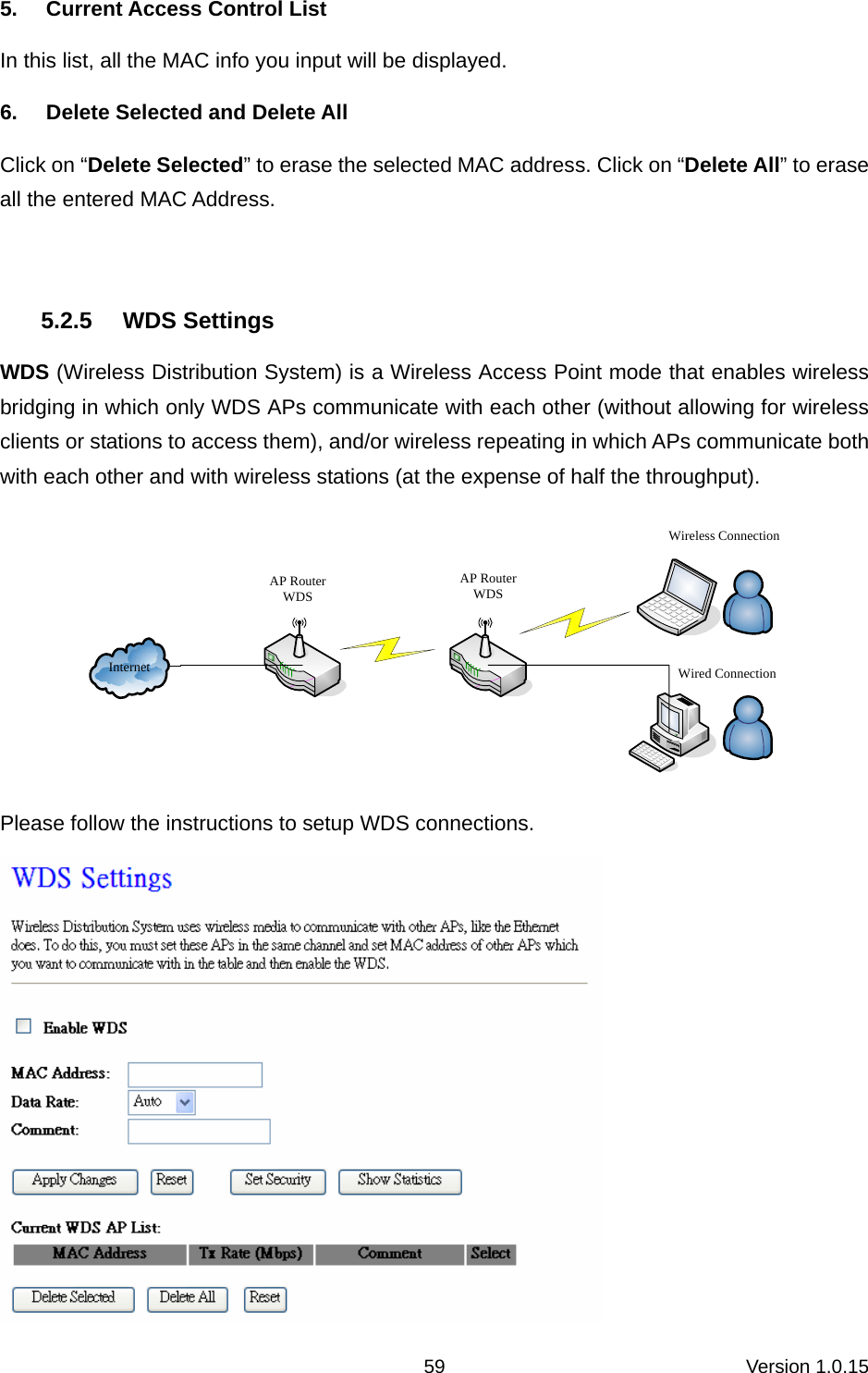
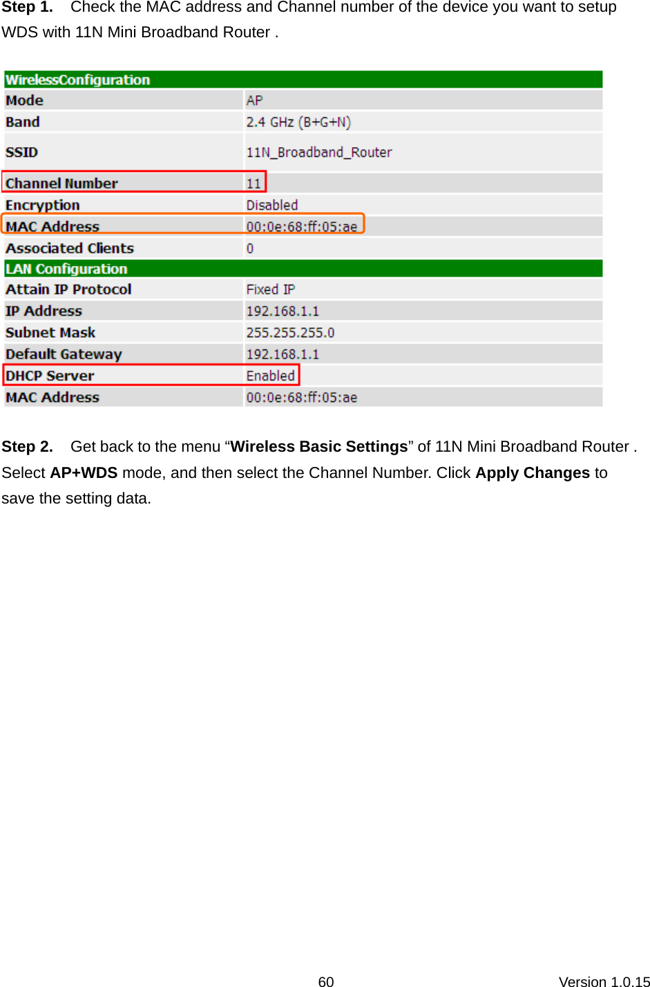
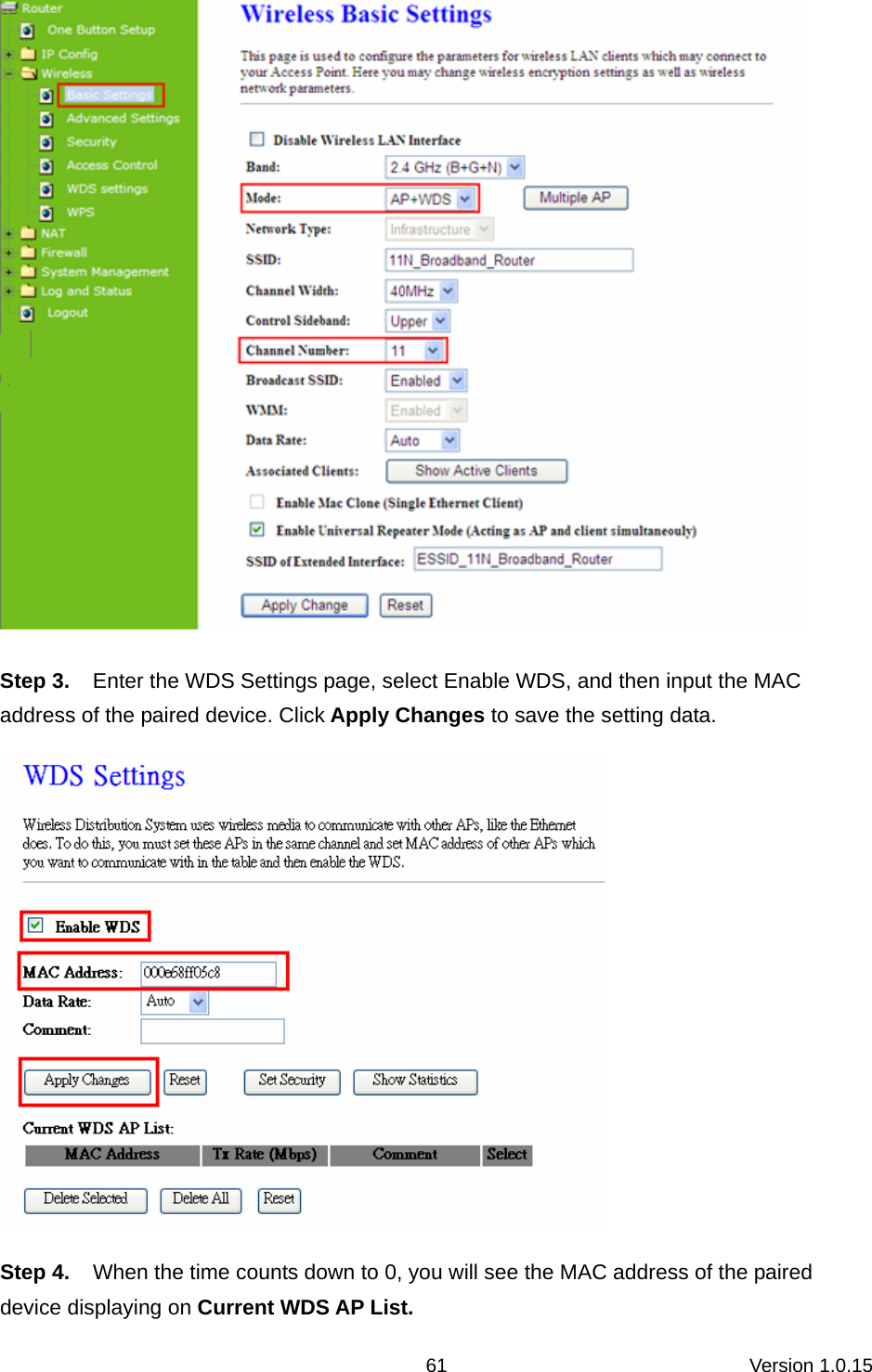
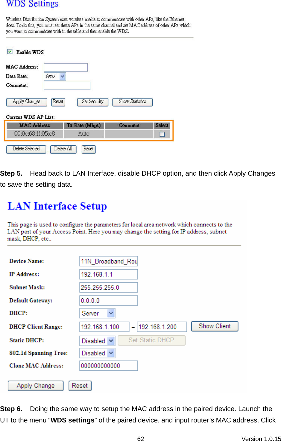
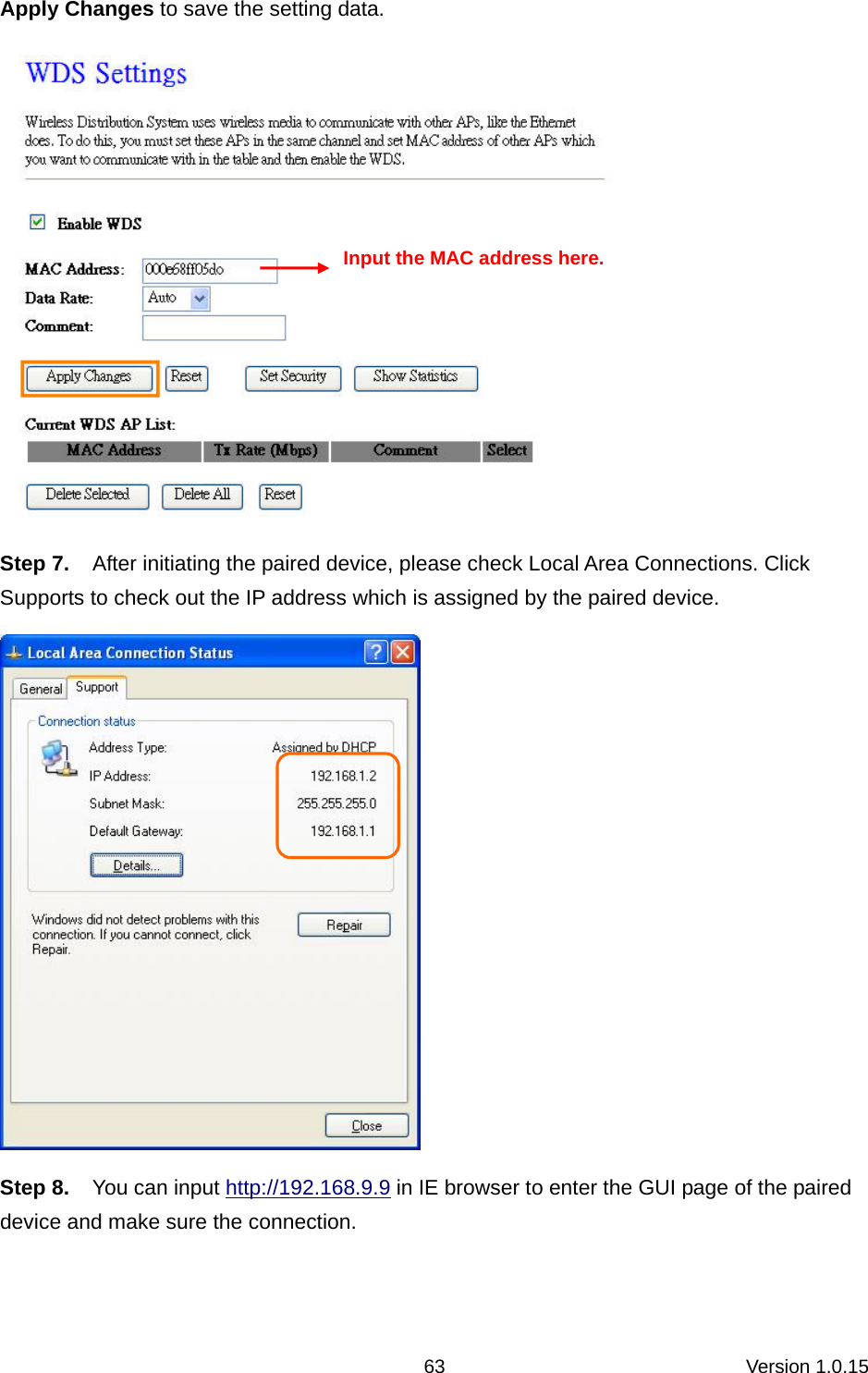
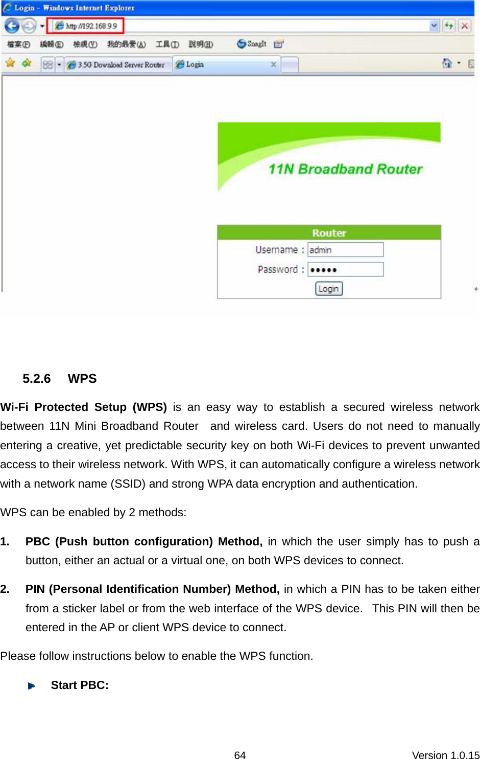
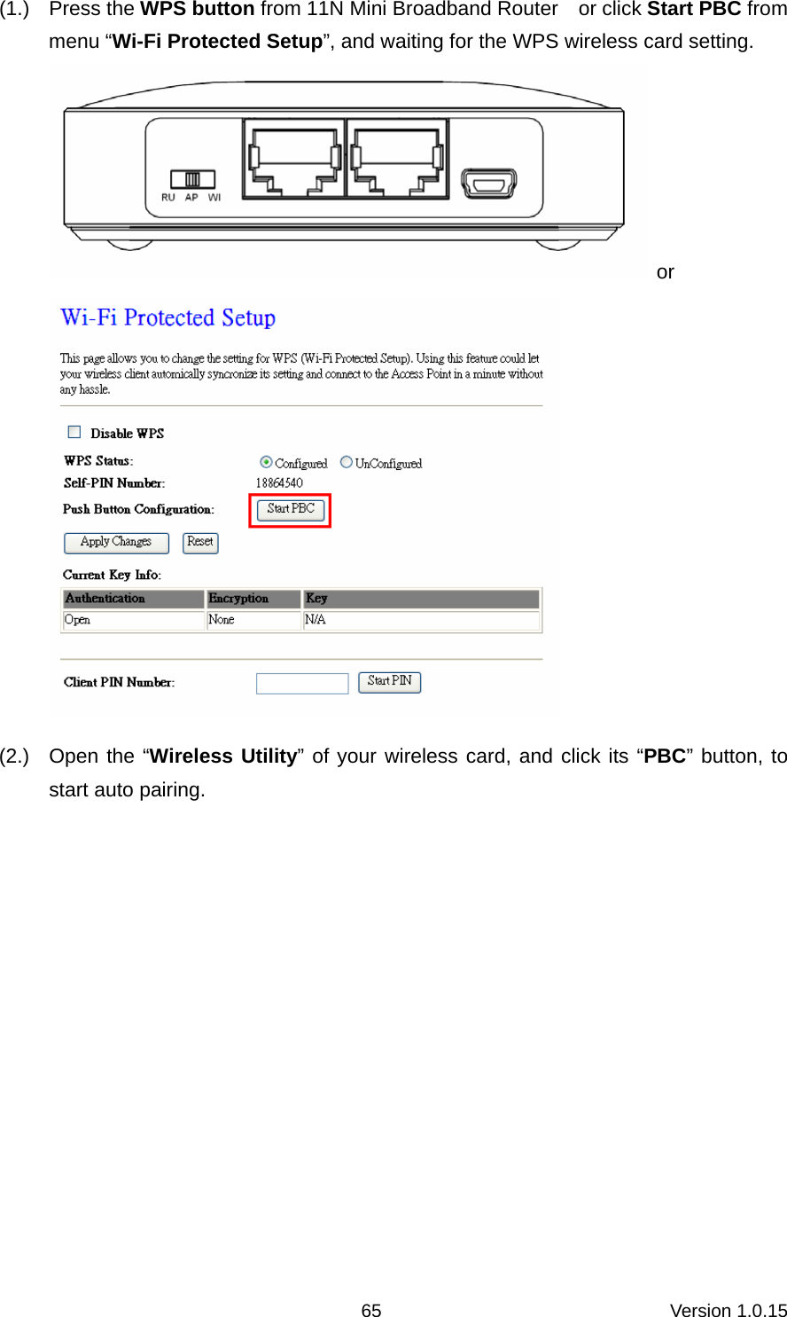
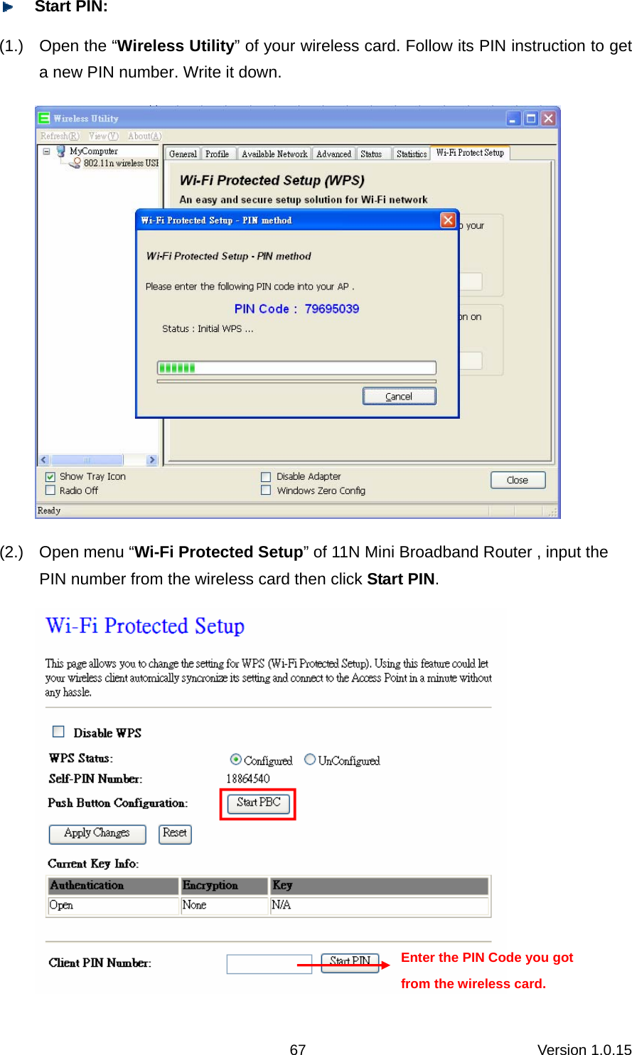
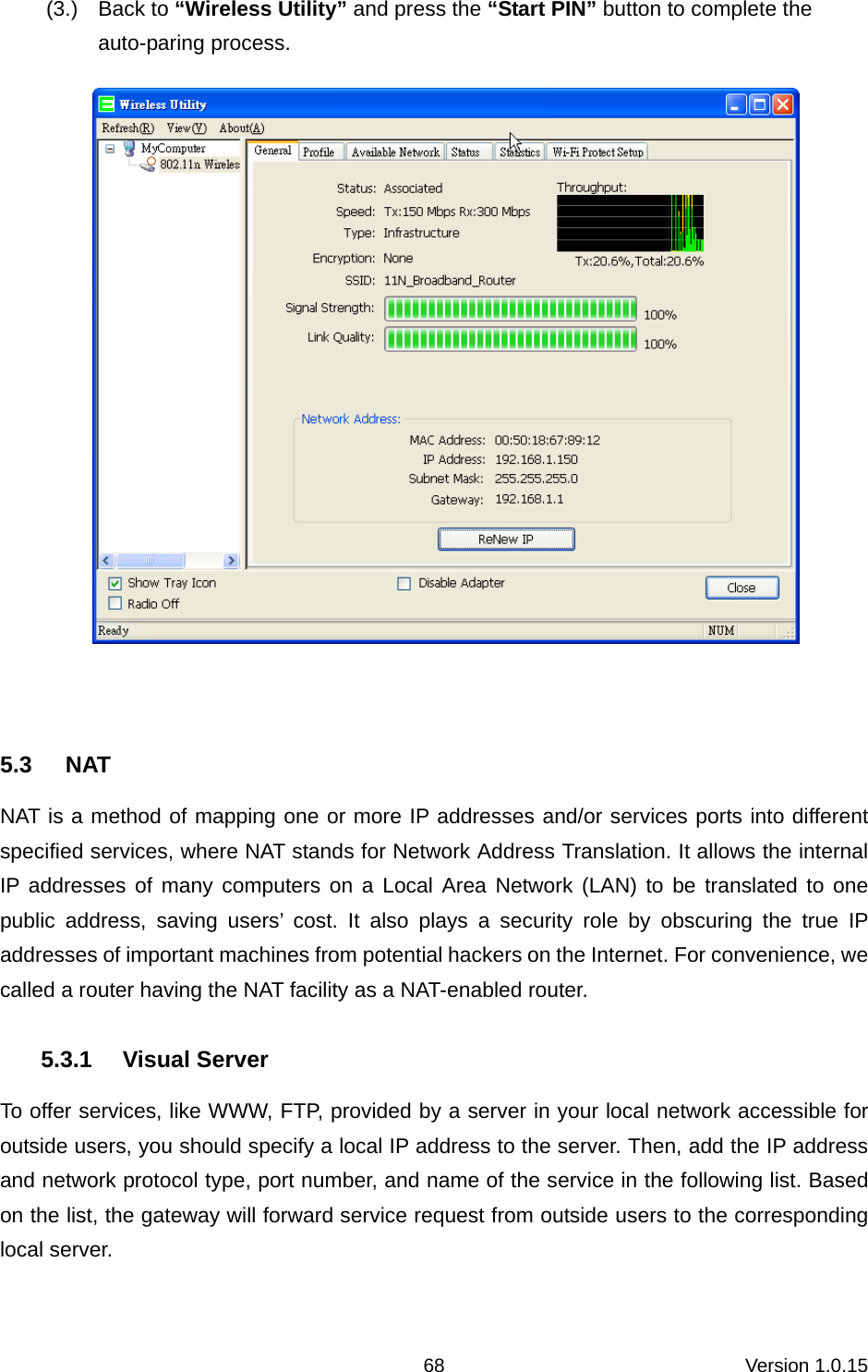
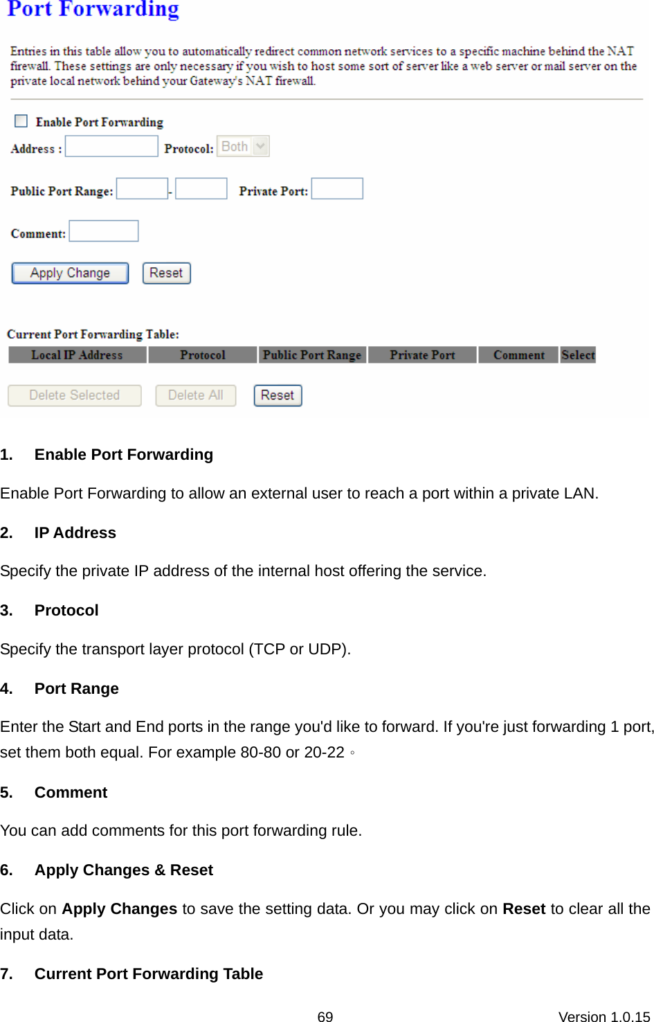
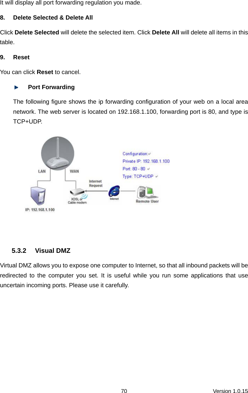
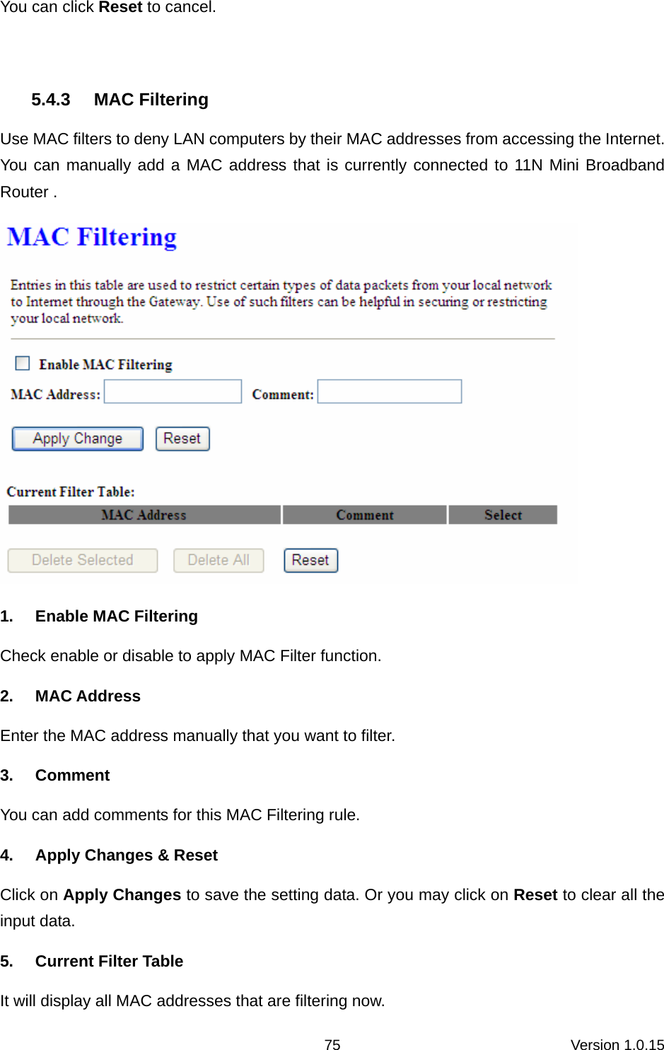
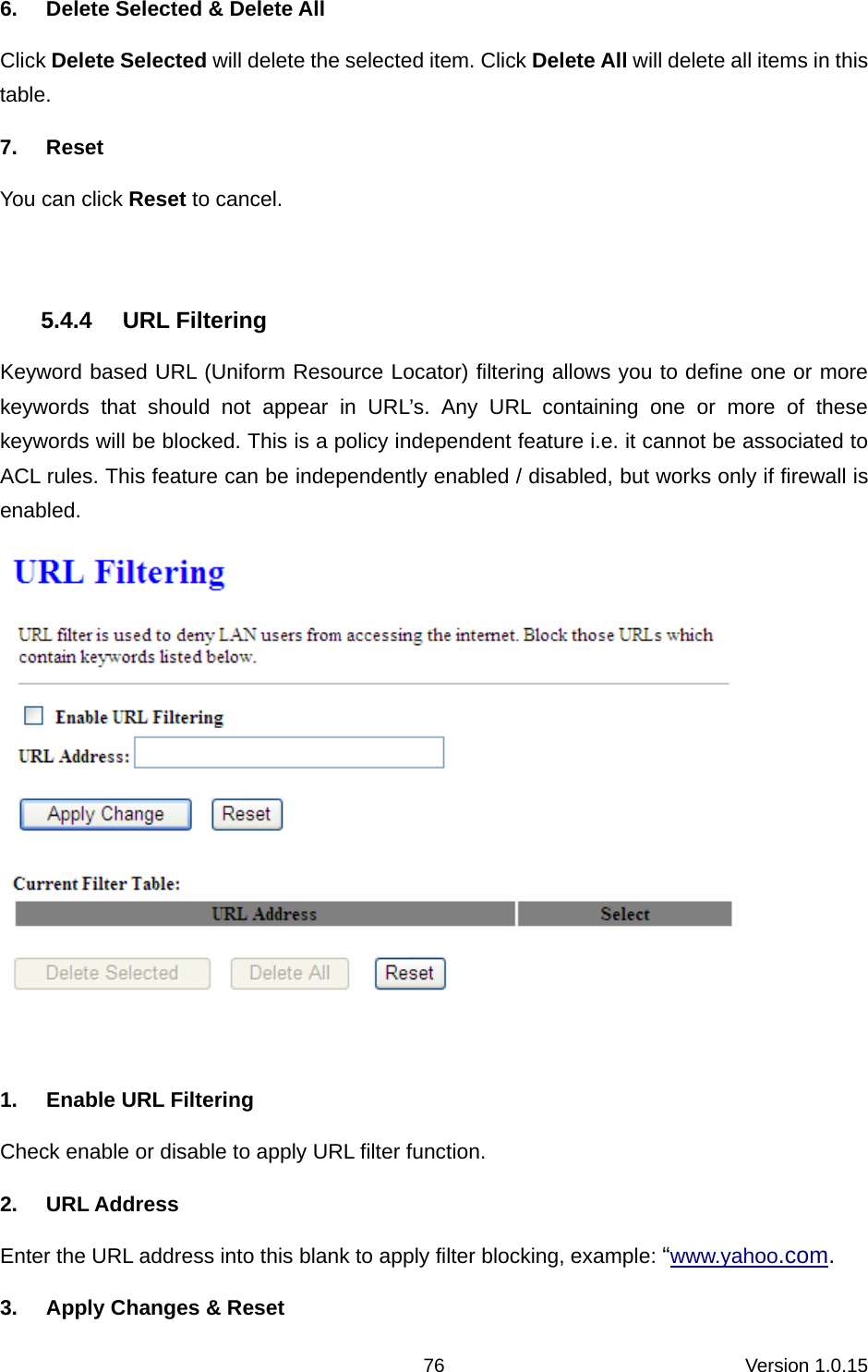
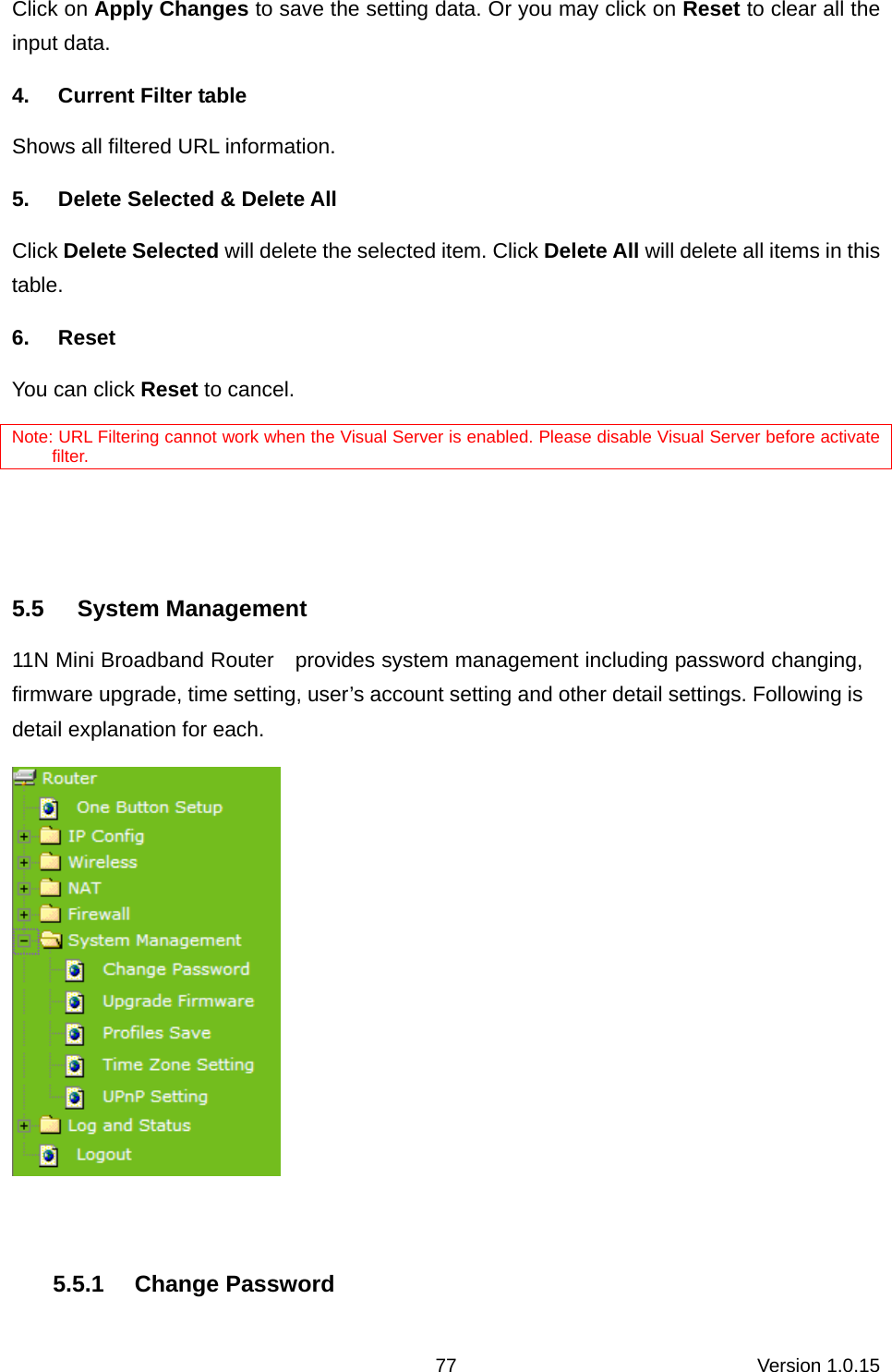
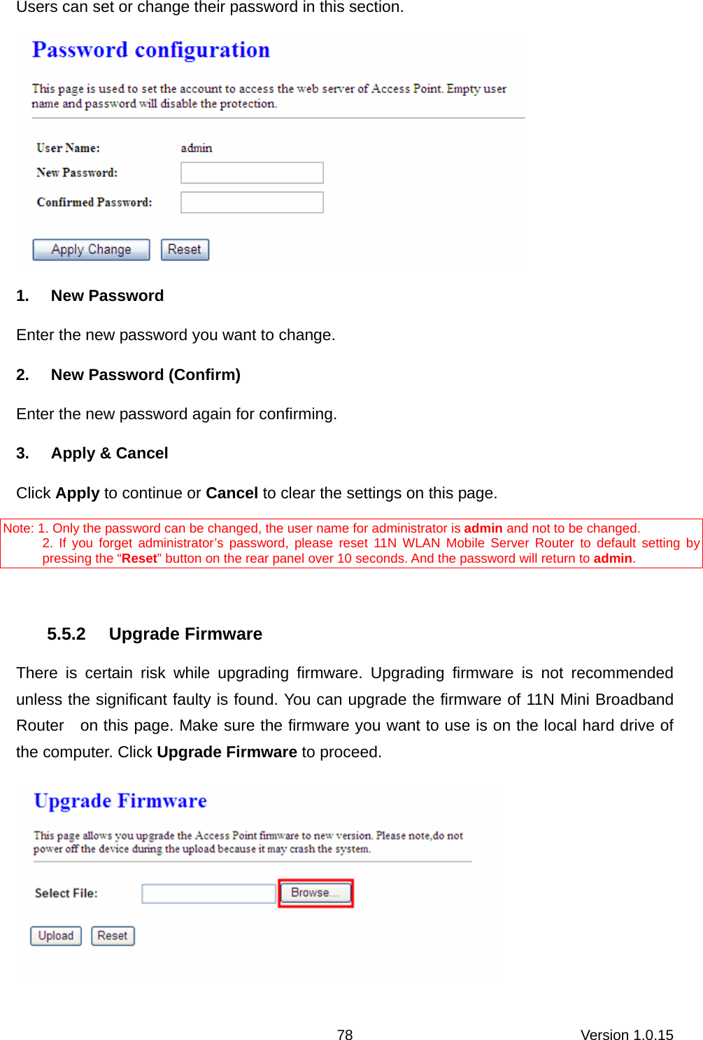
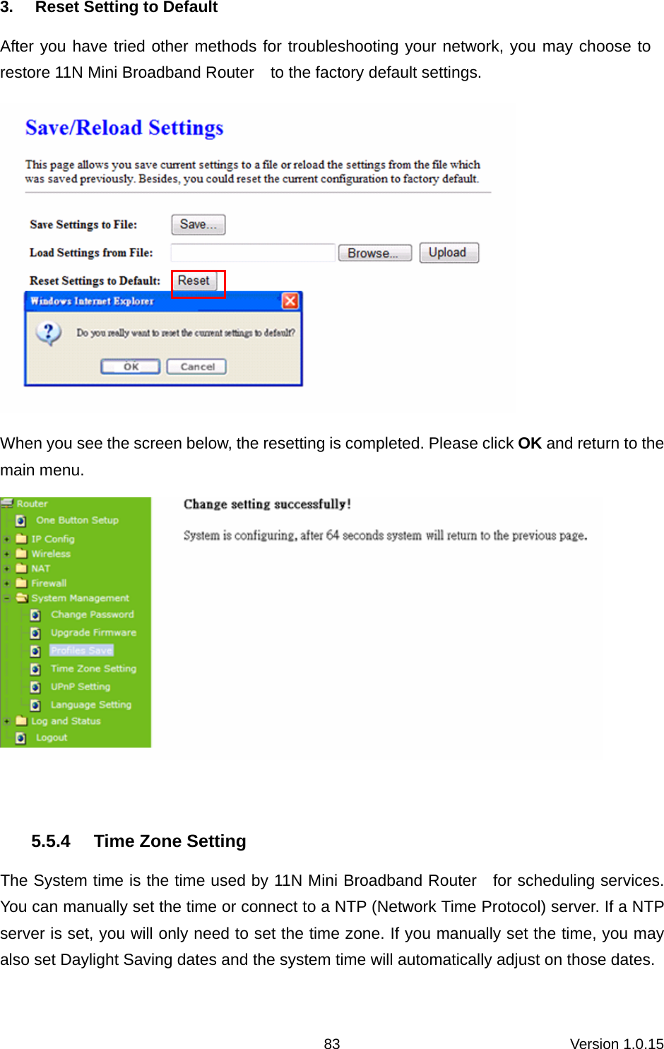
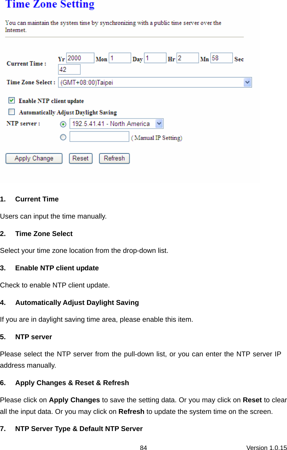
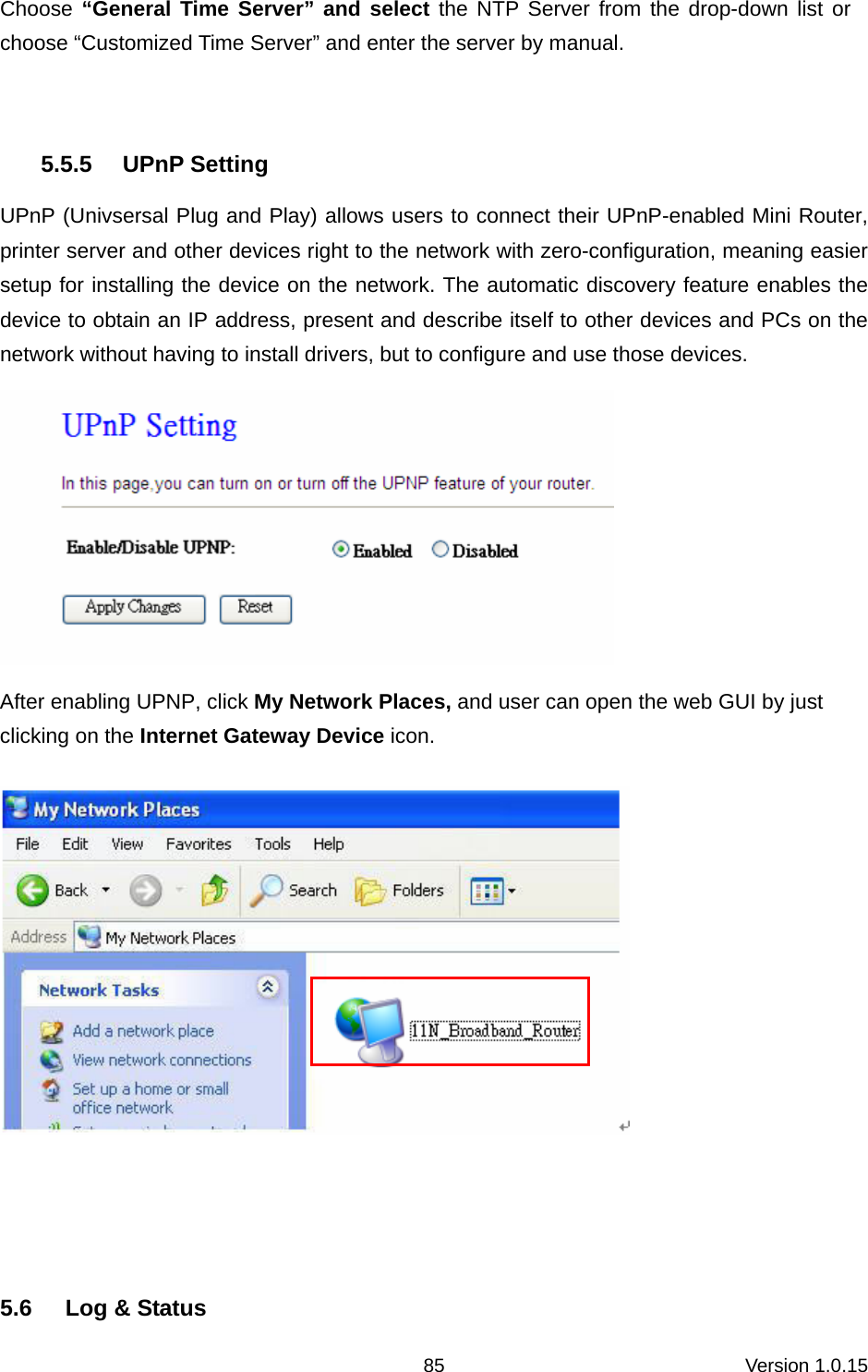
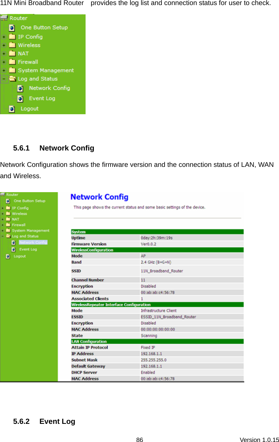
Planex Communications CQW-MR200 Wireless LAN Mobile Router User Manual 1
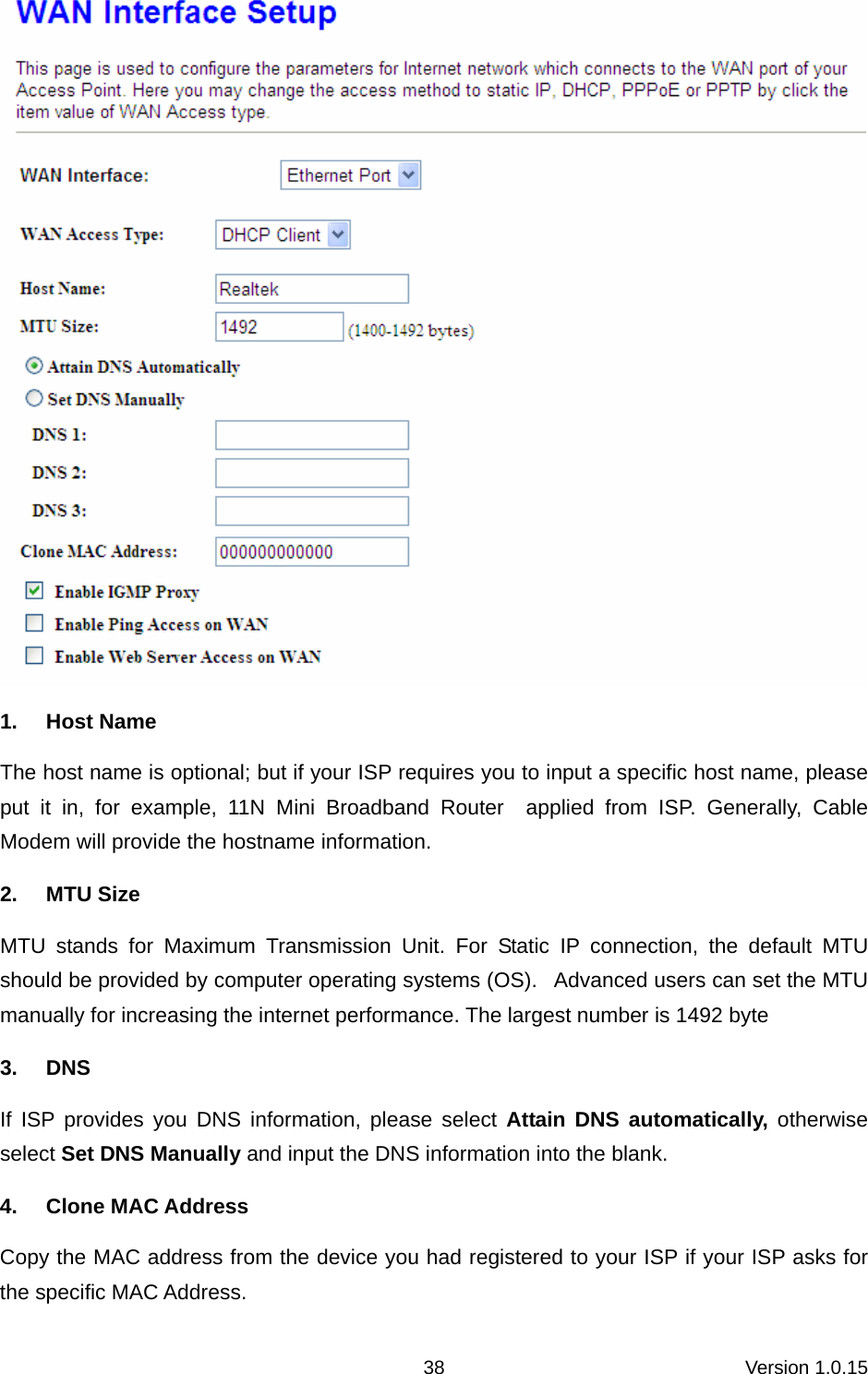
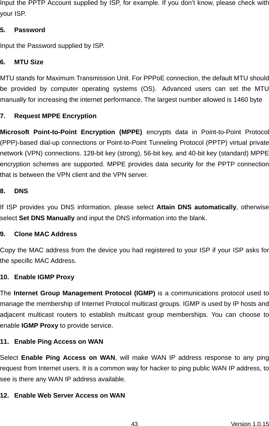
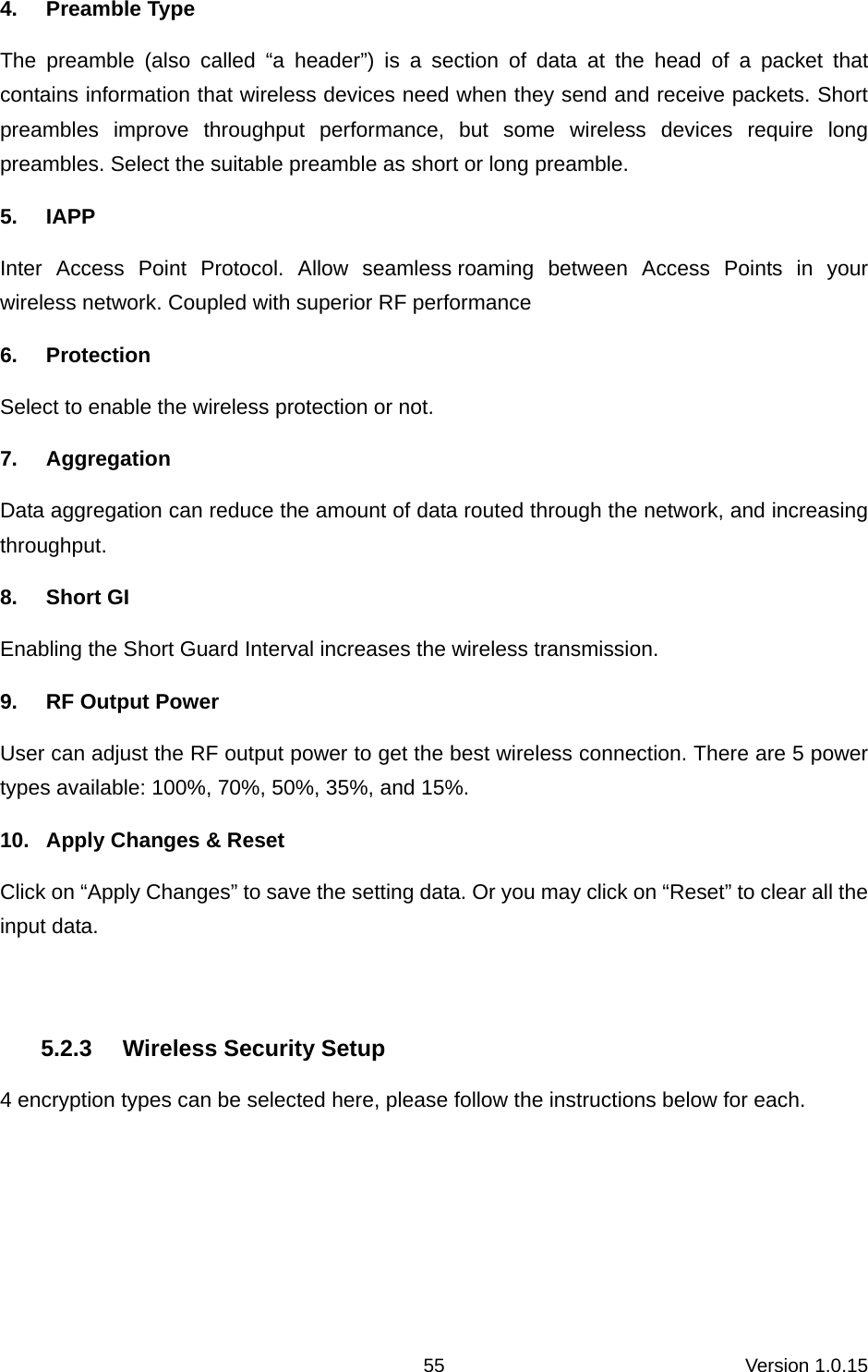
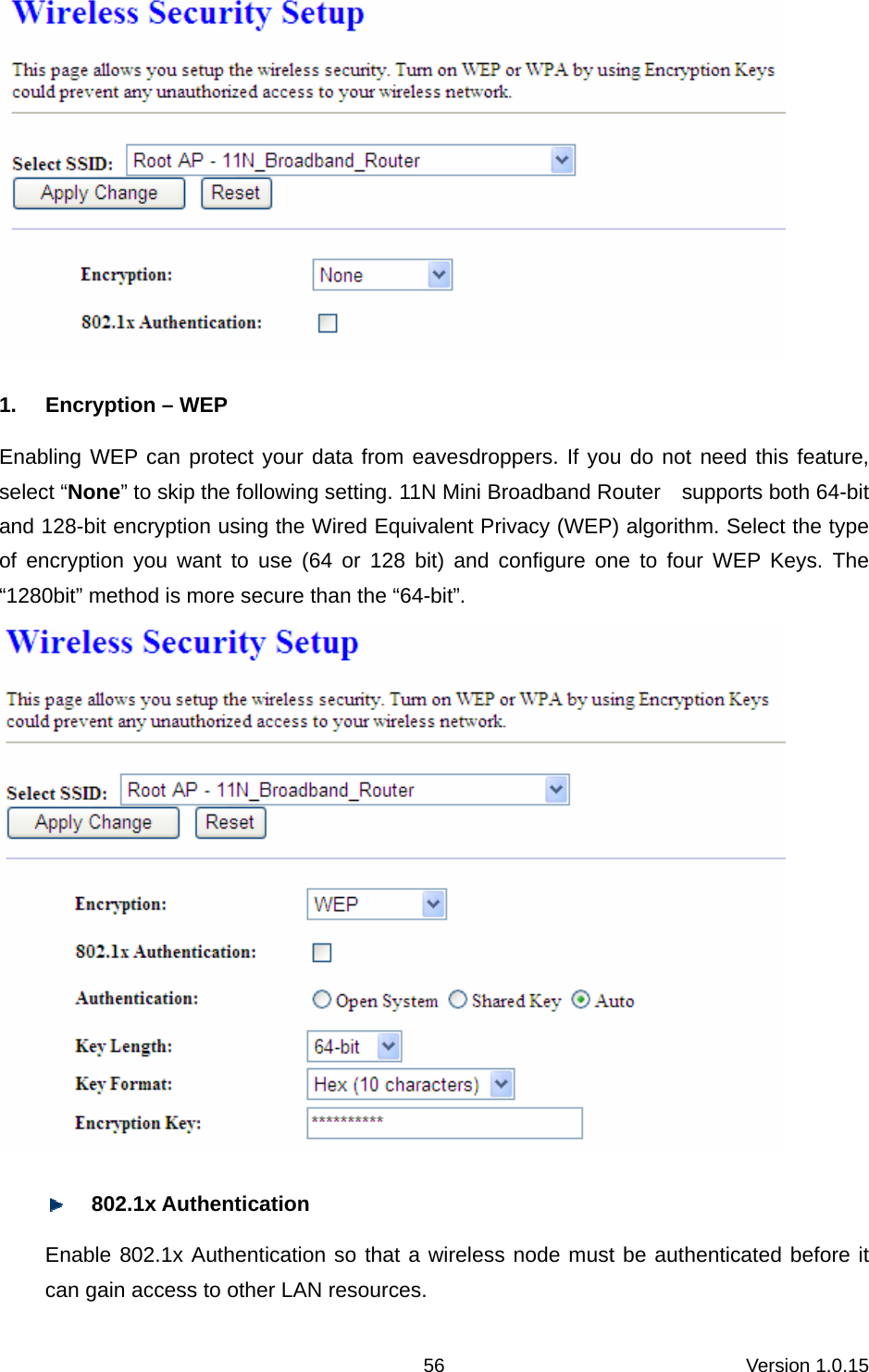
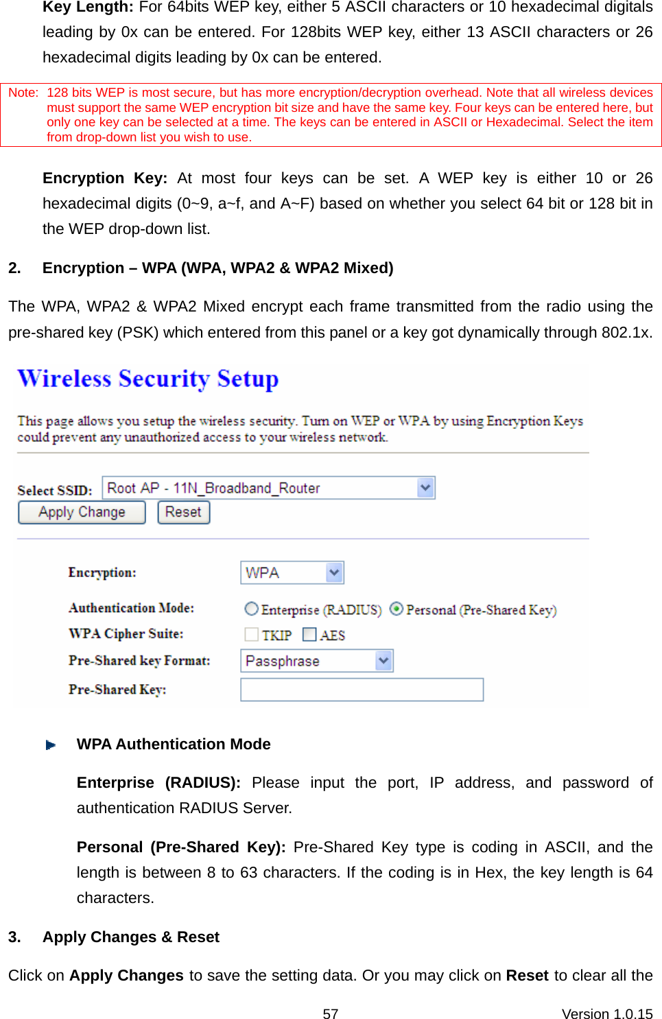
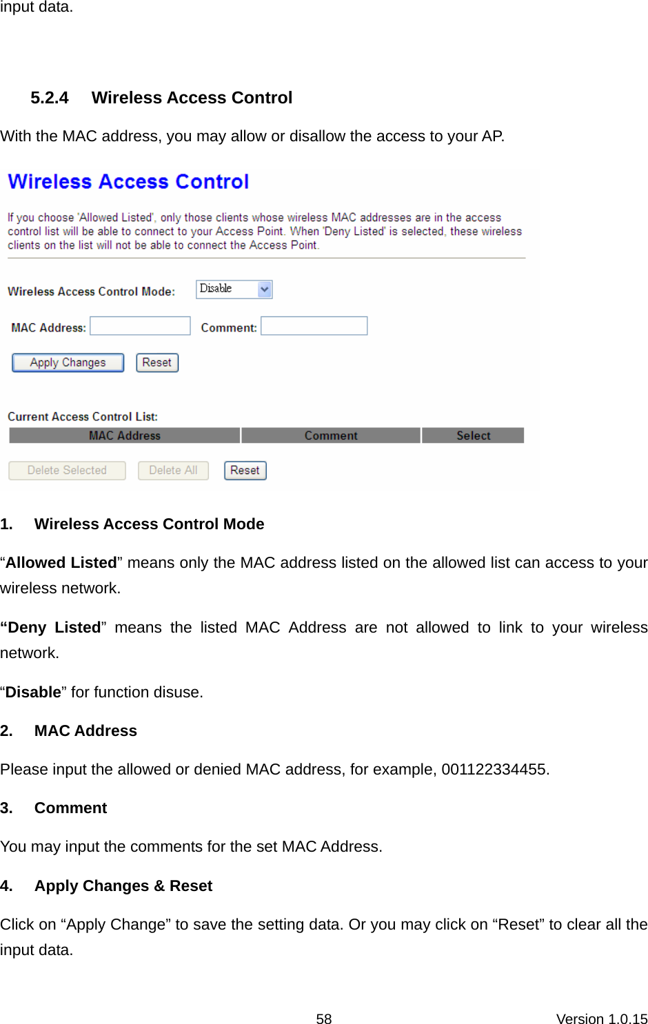
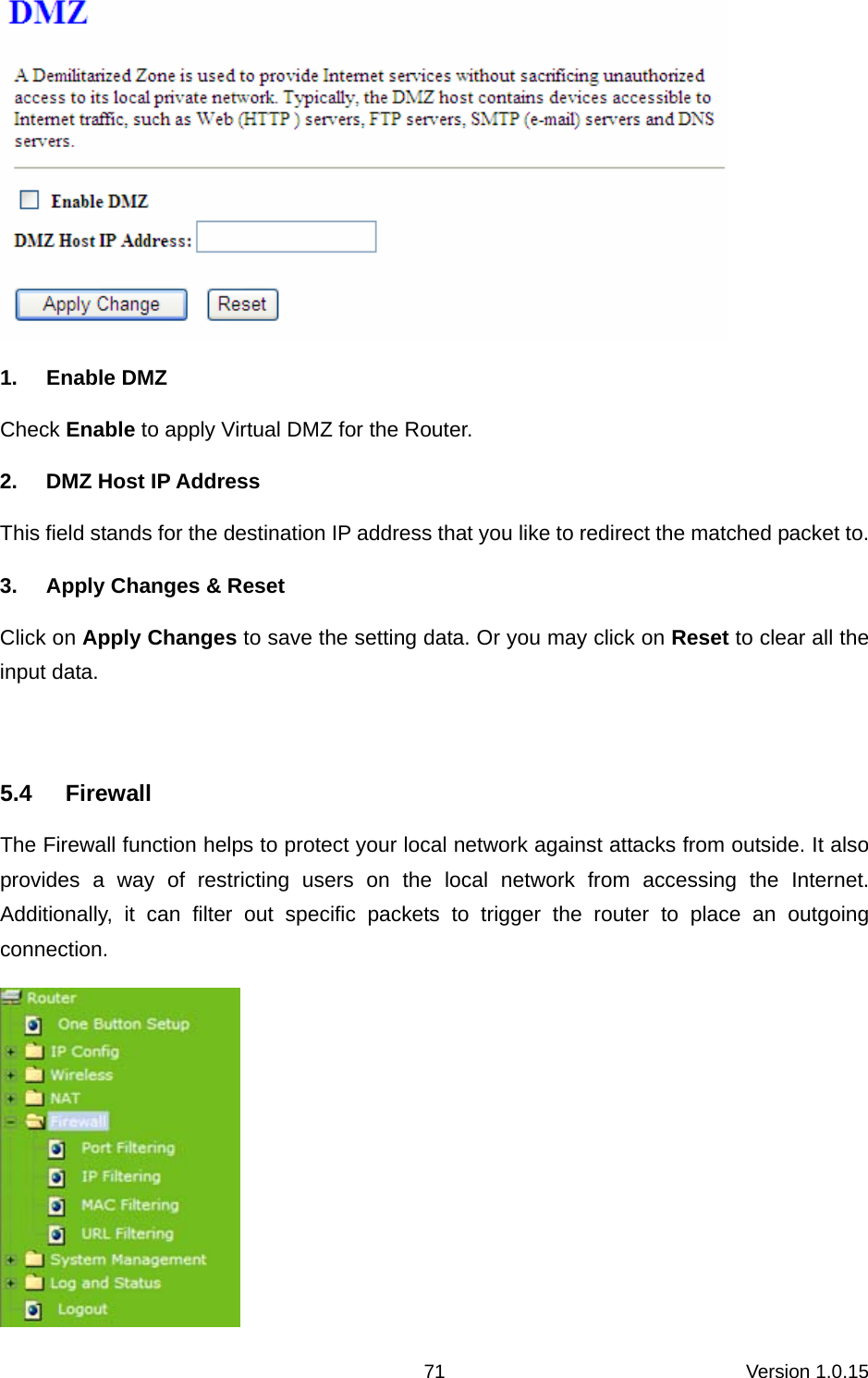
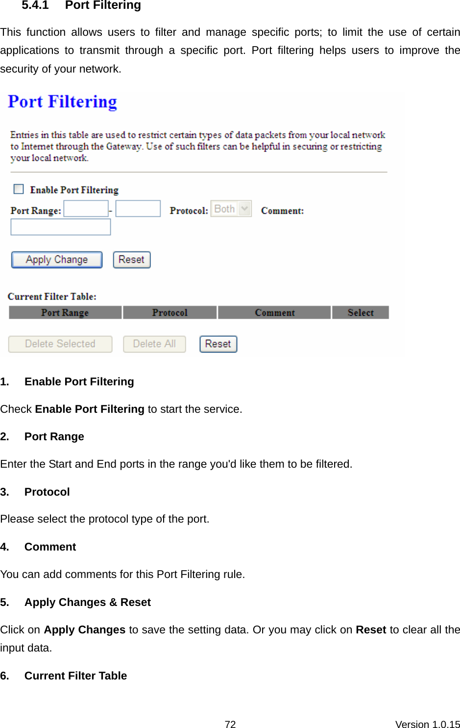
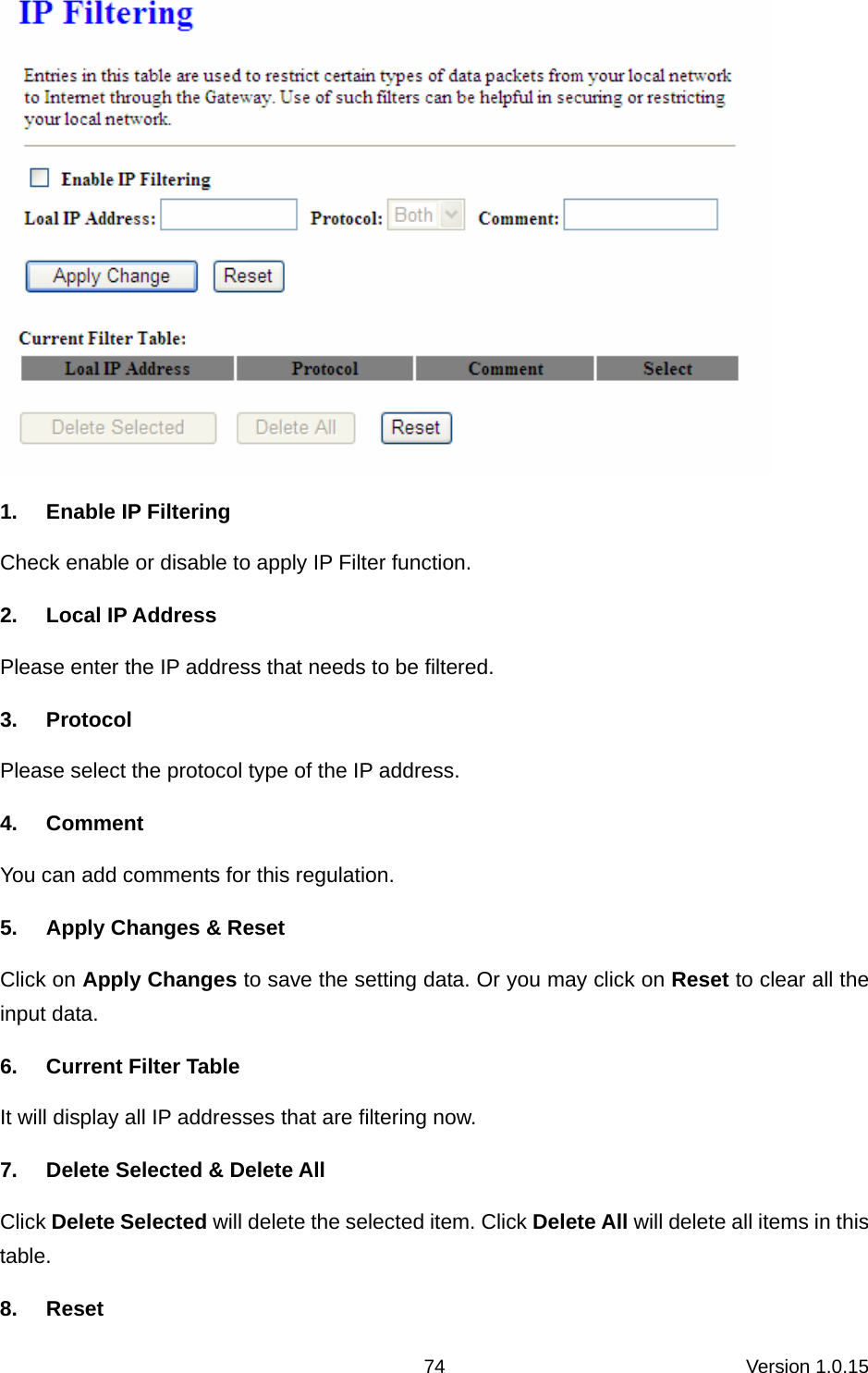
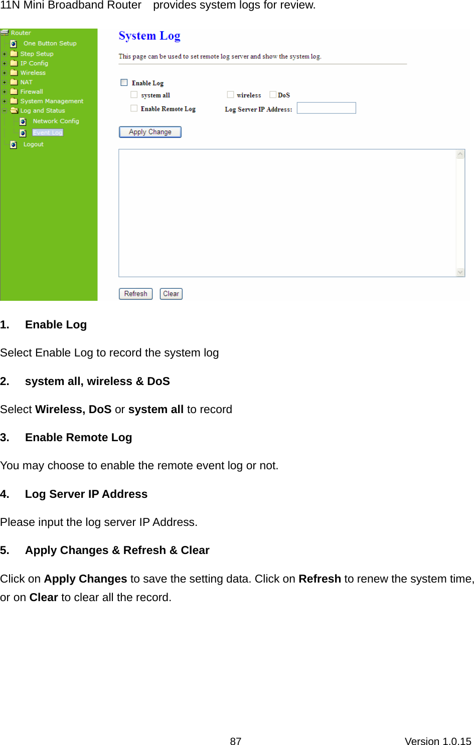
Planex Communications inc. Wireless LAN Mobile Router 1
UserManual.wiki
>
Planex Communications
>
CQW-MR200 User Manual
>
user manual 1
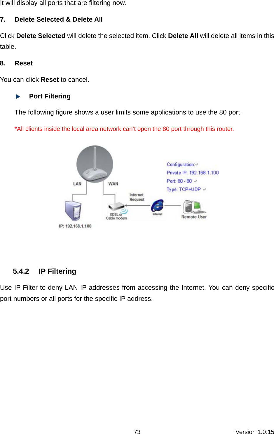
Contents
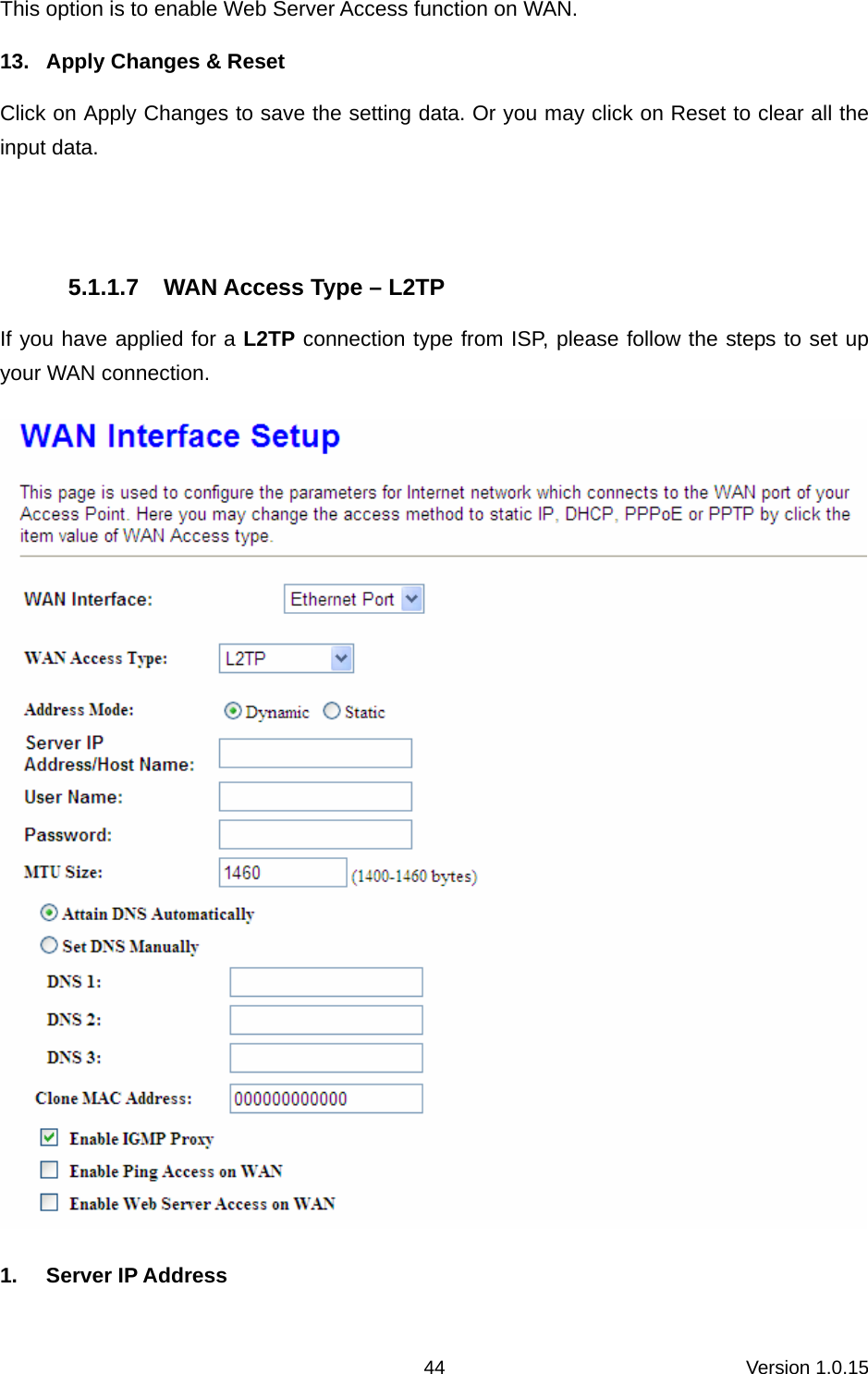
1.
user manual 1
2.
user manual 2
user manual 1
Navigation menu
Upload a User Manual
Namespaces
Wiki Guide
HTML
PDF
Info
Views
User Manual
Discussion / Help
Navigation