Planex Communications CQW-MR200 Wireless LAN Mobile Router User Manual 1
Planex Communications inc. Wireless LAN Mobile Router 1
Contents
- 1. user manual 1
- 2. user manual 2
user manual 1
Version 1.0.15
1
Wireless LAN Mobile Router
CQW-MR200 User Manual
Version 1.0.15
2
Table of Contents
FCC Caution ..........................................................................................................................................6
Safe Seating Gestures..........................................................................................................................7
CE Statement of Conformity ................................................................................................................7
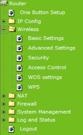
Chapter 1 Introduction .................................................................................................................8
1.1 Overview ......................................................................................................................8
Features.........................................................................................................................................9
1.2 Specifications............................................................................................................10
1.2.1 Six Views of Product Appearance ..................................................................11
1.2.2 LED Indicator Status Description ...................................................................11
1.3 System Requirements ..............................................................................................11
1.4 WAN Network Plug and Play....................................................................................12
1.5 Get Your IP Automatically & Manually ....................................................................12
1.5.1 Network Testing................................................................................................15
1.5.2 Testing with Internet Browser.........................................................................15
1.5.2.1 Testing with DOS (Windows XP Platform).........................................................16
Chapter 2 Hardware Installation................................................................................................18
2.1 Diagram of Connecting Hardware to 11N Mini Broadband Router......................18
2.1.1 Hardware Connection and Application for Router Mode .............................18
Hardware Connection and Application for AP Mode .....................................................19
2.1.2 Hardware Connection and Application for Wi-Fi AP Mode ..........................19
Chapter 3 One Button Setup......................................................................................................20
3.1 One Button Setup configuration for Router Mode ................................................20
3.2 One Button Setup configuration for AP Mode .......................................................22
3.3 One Button Setup configuration for WiFi AP Mode...............................................24
Chapter 4 Basic Setup................................................................................................................28
4.1 Router Mode ..............................................................................................................28
4.1.1 Switch to Router Mode ....................................................................................28
4.1.2 Administrator Setup Instruction.....................................................................28
4.2 AP Mode.....................................................................................................................29
4.2.1 Switch to AP Mode ...........................................................................................29
4.3 WiFi AP Mode ............................................................................................................30
4.3.1 Switch to WiFi AP Mode...................................................................................30
Chapter 5 Advanced Configuration for Router Mode .............................................................31
5.1 IP Configuration ........................................................................................................31
5.1.1 WAN ...................................................................................................................31
5.1.1.1 WAN Interface– Ethernet Port.............................................................................33
Version 1.0.15
3
5.1.1.2 WAN Interface– Wireless ....................................................................................34
5.1.1.3 WAN Access Type – Static IP..............................................................................35
5.1.1.4 WAN Access Type – Dynamic IP ........................................................................37
5.1.1.5 WAN Access Type – PPPoE................................................................................39
5.1.1.6 WAN Access Type – PPTP ..................................................................................42
5.1.1.7 WAN Access Type – L2TP...................................................................................44
5.1.2 LAN Interface Setup.........................................................................................46
5.1.3 Dynamic DNS Setting.......................................................................................47
5.2 Wireless Setup ..........................................................................................................49
5.2.1 Wireless Basic Settings...................................................................................49
5.2.2 Wireless Advanced Settings ...........................................................................54
5.2.3 Wireless Security Setup ..................................................................................55
5.2.4 Wireless Access Control .................................................................................58
5.2.5 WDS Settings....................................................................................................59
5.2.6 WPS ...................................................................................................................64
5.3 NAT .............................................................................................................................68
5.3.1 Visual Server.....................................................................................................68
5.3.2 Visual DMZ ........................................................................................................70
5.4 Firewall.......................................................................................................................71
5.4.1 Port Filtering .....................................................................................................72
5.4.2 IP Filtering.........................................................................................................73
5.4.3 MAC Filtering ....................................................................................................75
5.4.4 URL Filtering.....................................................................................................76
5.5 System Management ................................................................................................77
5.5.1 Change Password ............................................................................................77
5.5.2 Upgrade Firmware............................................................................................78
5.5.3 Save / Reload Settings.....................................................................................79
5.5.4 Time Zone Setting ............................................................................................83
5.5.5 UPnP Setting.....................................................................................................85
5.6 Log & Status ..............................................................................................................85
5.6.1 Network Config.................................................................................................86
5.6.2 Event Log ..........................................................................................................86
5.7 Logout........................................................................................................................88
Chapter 6 Advance Configuration for AP Mode ......................................................................88
6.1 IP Configuration ........................................................................................................89
6.1.1 LAN Setup .........................................................................................................89
6.1.2 LAN Interface Setup.........................................................................................89
6.2 Wireless Setup ..........................................................................................................90
Version 1.0.15
4
6.2.1 Wireless Basic Settings...................................................................................91
6.2.2 Wireless Advanced Settings ...........................................................................96
6.2.3 Wireless Security Setup ..................................................................................98
6.2.4 Wireless Access Control ...............................................................................102
6.2.5 WDS Settings..................................................................................................103
6.2.6 WPS .................................................................................................................108
6.3 System Management ..............................................................................................113
6.3.1 Change Password ..........................................................................................113
6.3.2 Upgrade Firmware..........................................................................................114
6.3.3 Save / Reload Settings................................................................................... 115
6.3.4 Time Zone Setting ..........................................................................................120
6.3.5 UPnP Setting...................................................................................................121
6.4 Log & Status ............................................................................................................122
6.4.1 Network Config...............................................................................................122
6.4.2 Event Log ........................................................................................................123
6.5 Logout......................................................................................................................124
Chapter 7 Advance Configuration for WiFi AP Mode............................................................125
7.1 IP Configuration ......................................................................................................125
7.1.1 LAN Setup .......................................................................................................125
7.1.2 LAN Interface Setup.......................................................................................125
7.2 Wireless Setup ........................................................................................................127
7.2.1 Wireless Basic Settings.................................................................................127
7.2.2 Wireless Advanced Settings .........................................................................132
7.2.3 Wireless Site Survey......................................................................................134
7.2.4 Wireless Security Setup ................................................................................135
7.2.5 Wireless Access Control ...............................................................................137
7.2.6 WPS .................................................................................................................139
7.3 System Management ..............................................................................................143
7.3.1 Change Password ..........................................................................................143
7.3.2 Upgrade Firmware..........................................................................................144
7.3.3 Save / Reload Settings...................................................................................145
7.3.4 Time Zone Setting ..........................................................................................149
7.3.5 UPnP Setting...................................................................................................151
7.4 Log & Status ............................................................................................................152
7.4.1 Network Config...............................................................................................152
7.4.2 Event Log ........................................................................................................153
7.5 Logout......................................................................................................................154
Chapter 8 DDNS Service Application......................................................................................155
Version 1.0.15
5
Chapter 9 Q & A ........................................................................................................................160
9.1 Installation ...............................................................................................................160
9.2 LED ...........................................................................................................................160
9.3 IP Address................................................................................................................161
9.4 OS Setting................................................................................................................161
9.5 11N Mini Broadband Router Setup .....................................................................163
9.6 Wireless LAN...........................................................................................................165
9.7 Support ....................................................................................................................167
9.8 Others.......................................................................................................................168
9.9 USB Device..............................................................................................................168
Chapter 10 Appendices..............................................................................................................169
10.1 Operating Systems .................................................................................................169
10.2 Browsers..................................................................................................................169
10.3 Communications Regulation Information ............................................................169
Version 1.0.15
6
FCC Caution
1. The device complies with Part 15 of the FCC rules. Operation is subject to the following
conditions:
(1) This device may not cause harmful interference, and
(2) this device must accept any interference received, including interference that may
cause undesired operation.
2. FCC RF Radiation Exposure Statement: The equipment complies with FCC RF radiation
exposure limits set forth for an uncontrolled environment. This equipment should be
installed and operated with a minimum distance of 20 centimeters between the radiator
and your body.
3. This Transmitter must not be co-located or operating in conjunction with any other
antenna or transmitter.
4. Changes or modifications to this unit not expressly approved by the party responsible for
compliance could void the user authority to operate the equipment.
FCC statement in User’s Manual (for class B)
Federal Communications Commission (FCC) Statement
This Equipment has been tested and found to comply with the limits for a class B digital
device, pursuant to Part 15 of the FCC rules. These limits are designed to provide reasonable
protection against harmful interference in a residential installation. This equipment generates,
users and can radiate radio frequency energy and, if not installed and used in accordance with
the instructions, may cause harmful interference to radio communications. However, there is
no guarantee that interference will not occur in a particular installation. If this equipment
does cause harmful interference to radio or television reception, which can be determined by
turning the equipment off and on, the user is encouraged to try to correct the interference by
one or more of the following measures:
- Reorient or relocate the receiving antenna.
- In crease the separation into an outlet on a circuit different from that to which the receiver
is connected.
- Consult the dealer or an experienced radio/TV technician for help.
Version 1.0.15
7
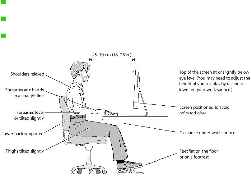
Safe Seating Gestures
You should follow the manufacturer’s instructions for adjusting the backrest to fit your body
properly.
An adjustable chair that provides firm, comfortable support is best.
Adjust the height of the chair so your thighs are horizontal and your feet flat on the floor.
The back of the chair should support your lower back (lumbar region).
CE Statement of Conformity
Our product has been tested in typical configuration by Ecom Sertech Corp and was found to
comply with the essential requirement of “Council Directive on the Approximation of the Laws
of the Member States relating to Electromagnetic Compatibility” (89/336/EEC; 92/31/EEC;
93/68/EEC)
Version 1.0.15
8
Chapter 1 Introduction
1.1 Overview
11N Mini Broadband Router might be small in size, but is huge in functionality. It supports
multiple operation modes, including Access Point (AP) mode, Router mode, and WiFi AP
mode. You can switch among these modes easily by using its 3-way configuration switch.
Version 1.0.15
9
Features
y Small in size but huge in functionality; the world No.1 Mobile Router for traveler
y Three modes to be switched; Router, AP and WiFi AP
y WPS button provides not only an easy and secured wireless network but also a WDS
repeater in one push
y Multiple APs Supported: adds or limits the properties for classed SSID, increasing the
flexibility and efficiency of the network.

Version 1.0.15
10
1.2 Specifications
WAN Port 1 x 10/100 Mbps RJ45, with auto MDI/MDIX
LAN Port 1 x 10/100 Mbps RJ45, with auto MDI/MDIX
Wireless Built-in Mini PCI
Interface
Slide Switch Router / AP / WiFi AP mode exchange function.
Web-Base Windows IE / Linux Firefox / MAC Safari
WAN Protocol PPPoE / PPTP / Static IP/ Dynamic IP/ L2TP
WLAN WDS / WEP Key / WPA / WPA-PSK / WPA2 / WPA2-PSK / MAC Access
Control /Hidden SSID
Routing UPnP / DHCP / DNS / WINS / DDNS
NAT Virtual Server / Virtual DMZ
Firewall MAC Filter / URL Filter / SPI / DoS Protection / IP Packet Filter
Function
Operation
Requirement
Operating Temp. 0°C~40°C (32°F~104°F)
Storage Temp. -20°C~70°C (-14°F~158°F)
Operating Humidity 10% to 85% Non-Condensing
Storage Humidity 5% to 90% Non-Condensing
Peak Gain of the
Antenna 2dBi @ 2.45GHz
Transmitted Power
(Typical)
802.11b: 18±3dBm @ normal temp. rang e
802.11g: 17±3dBm @ normal temp. rang e
802.11n (20MHz/40MHz): 16±3dBm @ normal temp. range
Others
Receive
Sensitivity (Typical)
11Mbps : TYP. -83dBm @ 8% PER
54Mbps: TYP. -70dBm @ 10% PER
11n (20MHz): TYP. -64dBm @ 10% PER
11n (40MHz): TYP. -61dBm @ 10% PER
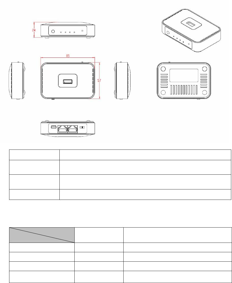
Dimension 88mm (L) x 58mm (W) x 24mm (H)
Application Power Power Adapter DC5V/1A with mini-USB B type male connector
Note: 1. Firmware Upgrade available through download.
Version 1.0.15
11
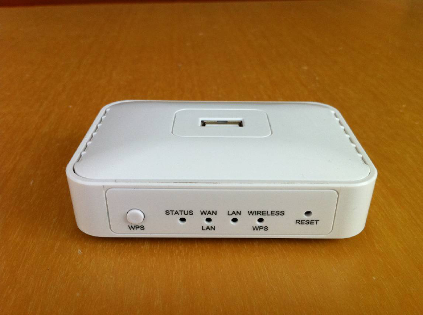
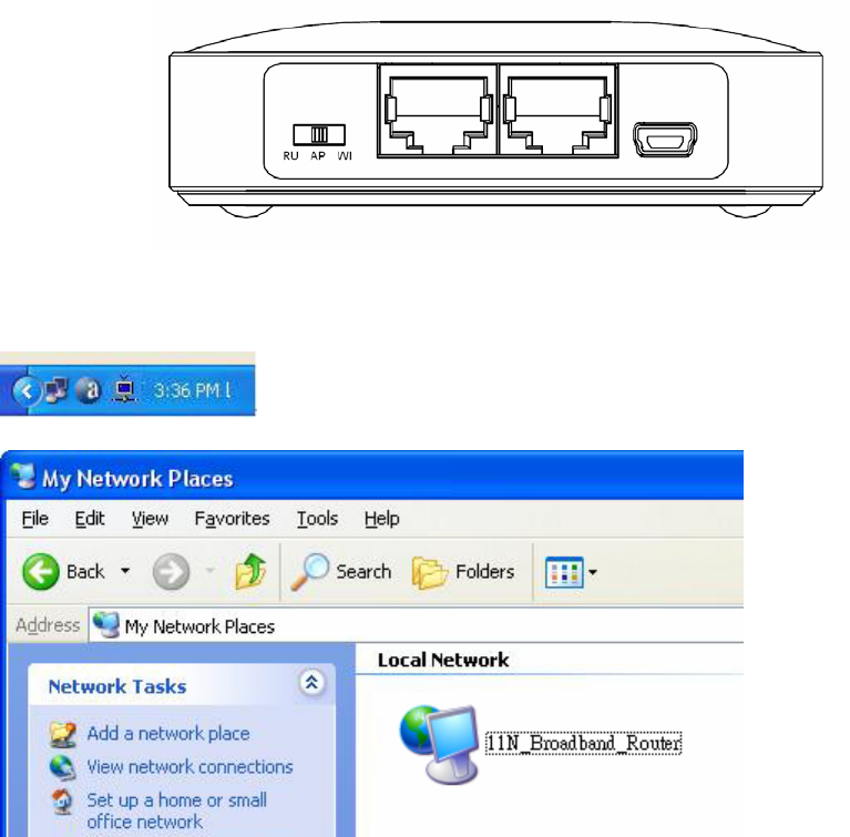
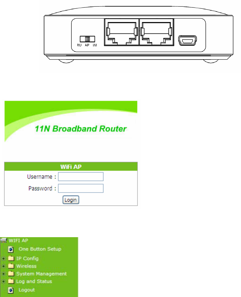
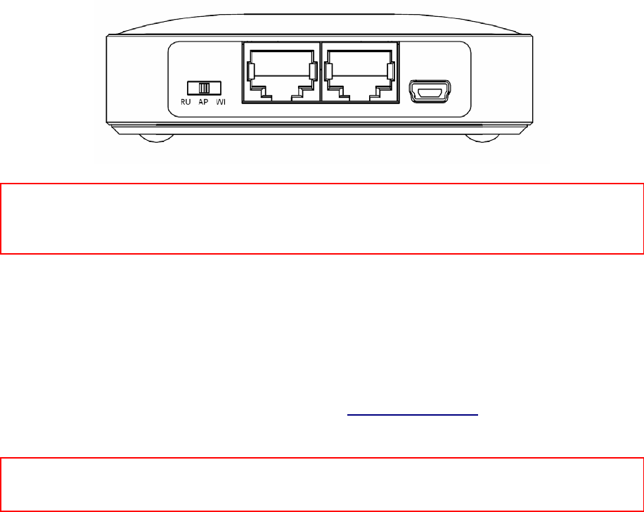
1.2.1 Six Views of Product Appearance
Power Plug Power Adapter DC5V/0.5A with mini-USB B type male connector
Operation Mode
Switch Router, AP, and WiFi AP operation modes
Reset Button Press “Reset” button over 10 seconds. When status indicator turns from
flashing to solid, the process is completed. All settings are back to default.
Ethernet Port 2 RJ-45 Ethernet 10/100 Ports
1.2.2 LED Indicator Status Description
Status
LED Indicator Solid Flashing
STATUS Operation OK Green: Reset / Firmware updates in progress
LAN RJ-45 Plugged in Transmitting Data
WAN RJ-45 Plugged in Transmitting Data
WIRELESS & WPS Operation OK Green: Transmitting Data
Reddish Orange: WPS enabled
1.3 System Requirements

Version 1.0.15
12
To begin with 11N Mini Broadband Router , you must have the following minimum system
requirements. If your system can’t correspond to the following requirements, you might get
some unknown troubles on your system.
XDSL/Cable Modem and broadband Internet Account.
One Ethernet (10 BASE-T or 10/100 BASE-TX) network interface card.
CP/IP and at least one web browser software installed (E.g.: Internet Explorer 5.0,
Netscape Navigator 7.x, Apple Safari 2.03 or higher version).
At lease one 802.11g (54Mbps) or one 802.11b (11Mbps) wireless adapter for wireless
mobile clients.
Recommended OS: Win2000 or WinXP / Linux.
1.4 WAN Network Plug and Play
WAN Type auto-detection:
When using Ethernet auto-connection:
¾ Auto-detection mode only applies on PPPoE, DHCP, PPTP and L2TP.
¾ Router will detect WAN type and load the settings from last time or display
corresponding page for user to input information.
¾ If there is no setting from user, the router will load the default settings.
If there is no setting from user, it will detect ISP and load corresponding settings.
1.5 Get Your IP Automatically & Manually
After 11N Mini Broadband Router connected with your computer, please make sure your IP
is in the automatic IP position or you adjust it manually in order to activate the Internet
network from home to Internet. If you don’t know how to enter the settings, please follow the
steps as below.
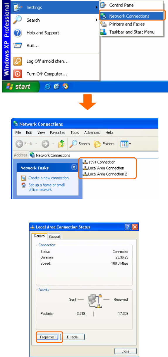
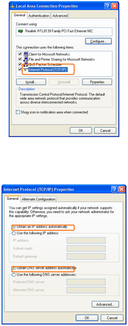
Step 1. Go to Start>Settings> Network Connections and then select Local Area
Connection.
Version 1.0.15
13
Step 2. Click on Properties
Step 3. Double click on Internet Protocol (TCP/IP).
Version 1.0.15
14
Step 4-1. For getting IP automatically if you are one of the users under 11N Mini Broadband
Router , please skip Use the following IP address and then select Obtain an IP address
automatically and Obtain DNS server address automatically and then click on OK button.
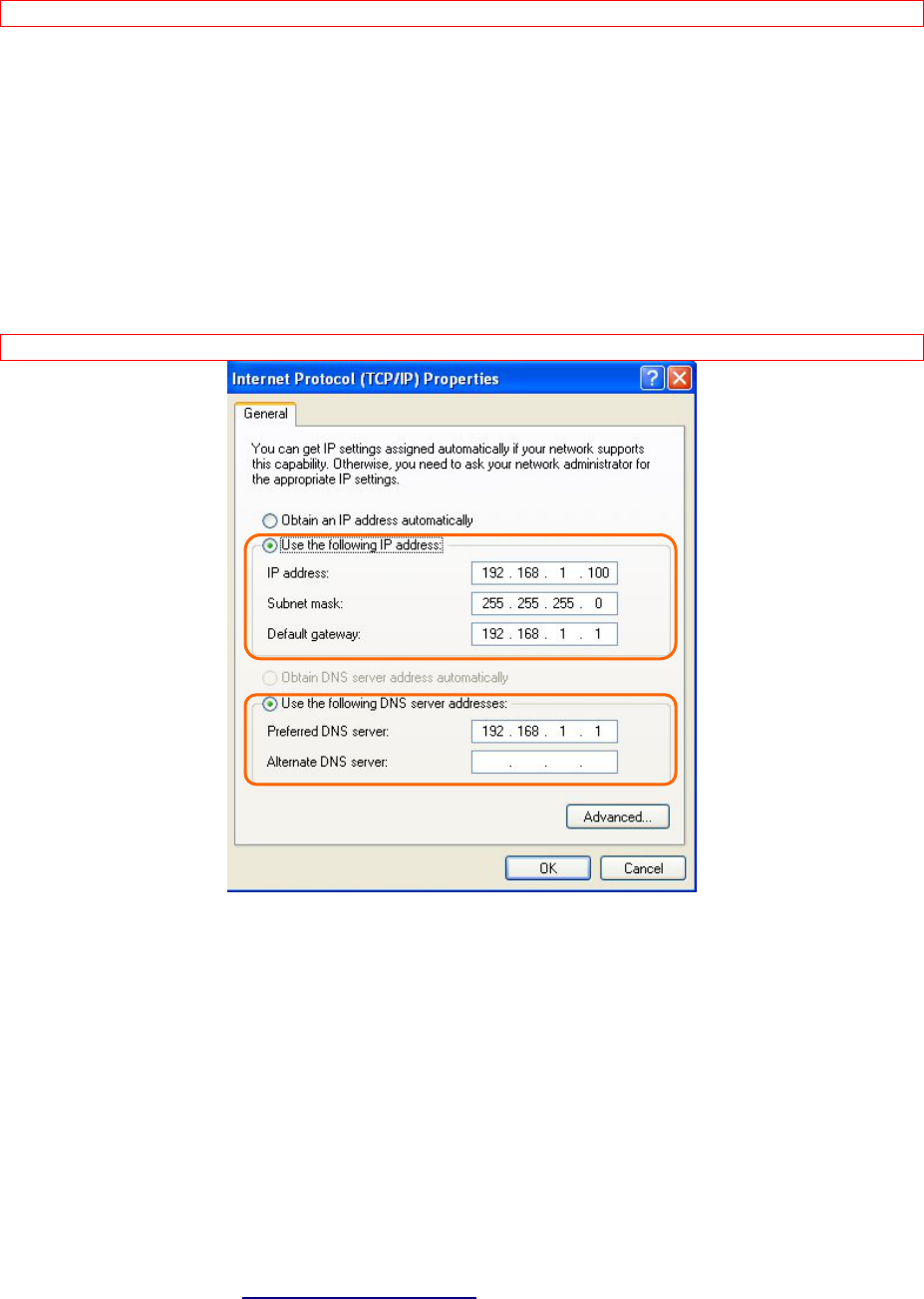
Step 4-2. For getting IP manually in order to specify a Virtual Server, such as Print Server,
FTP Server and so on, please skip Obtain an IP address automatically and then select Use
the following IP address. And the following default setting of 11N Mini Broadband Router
should be noted:
y IP Address: 192.168.1.10 (as your Print Server for example)
y Subnet Mask: 255.255.255.0
Version 1.0.15
15
y Default Gateway: 192.168.1.1
Note: If you configure your computer’s IP Address manually, it needs to be on the same network segment.
For example:
z IP Address: 192.168.1.xxx (xxx can be any number between 2 and 253, but it can’t be
repeated, we use 100 to be the example.)
z Subnet Mask: 255.255.255.0
z Gateway: 192.168.1.1 (this is the IP address of 11N Mini Broadband Router in Router
Mode)
z DNS: 192.168.1.1 (use 11N Mini Broadband Router ’s IP address or on your own choice)
Note: IP address and Default gateway cannot be the same.
1.5.1 Network Testing
There are two ways to test your Network whether it can work on Internet or not. They are
“Testing with Internet Browser” and “Testing with Dos”.
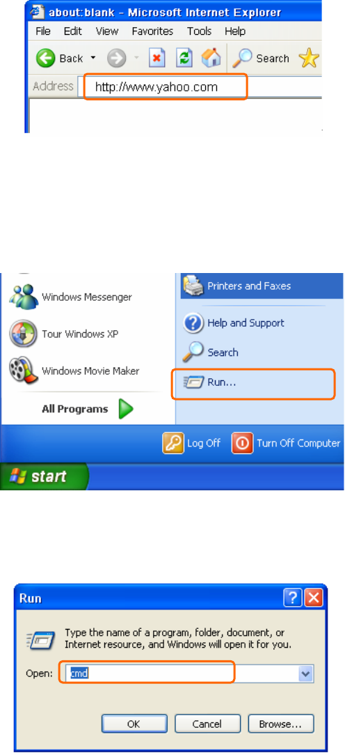
1.5.2 Testing with Internet Browser
Open an Internet Browser, such as Internet Explore or Netscape. Input a valid web address
you like, for example, http://www.yahoo.com in the web address blank and then press
enter. If the website appears, that means your Internet is working under normal situation.
Version 1.0.15
16
1.5.2.1 Testing with DOS (Windows XP Platform)
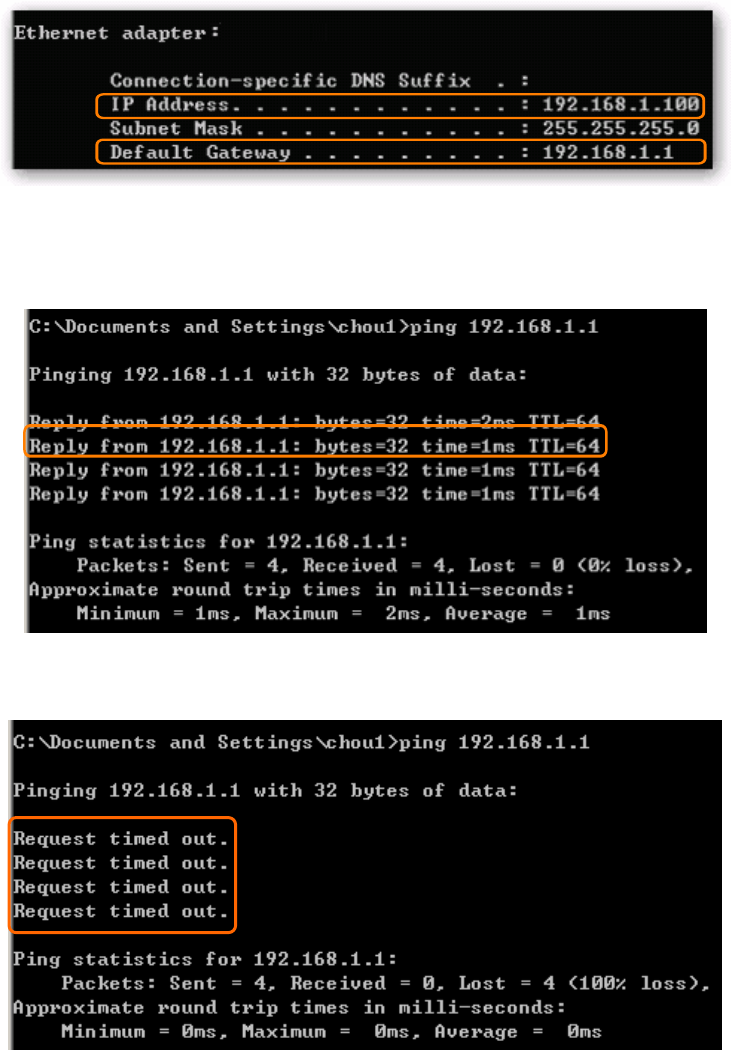
Step 1. Go to start -> Run.
Step 2. Input cmd in the blank, and then click OK button. The Command Prompt window
appears.
Step 3. Input ipconfig in the flashing area then press enter. You will get an IP Address
192.168.1.100, for example, and Default Gateway as 192.168.1.1.
Version 1.0.15
17
Step 4. Ping a legal WAN Address such as 192.168.1.1. If Internet works, it will show Reply
from 192.168.1.1: bytes = 32 time = 3ms TTL =64, for example.
If it can’t work, it will show Request timed out.

Version 1.0.15
18
Chapter 2 Hardware Installation
2.1 Diagram of Connecting Hardware to 11N Mini Broadband Router
11N Mini Broadband Router is a portable and convenient wireless solution for the traveling
businessmen delivering 802.11n wireless connectivity with a maximum wireless signal rate of
up to 300Mbps. Use it in conference rooms, hotel rooms, or even at hotspots. The Wireless
Pocket Router/AP might be small in size, but is huge in functionality, supporting multiple
operation modes, including Access Point (AP) mode, Router mode, and WiFi AP mode. You
can switch among these modes easily by using 11N Mini Broadband Router 's 3-way
configuration slide switch.
Warning: Before sliding the switch modes, please power-off the router firstly. Moreover, please stay over 10
seconds between power-off / power-on condition.
2.1.1 Hardware Connection and Application for Router Mode
When 11N Mini Broadband Router switches to Router Mode, there will be each WAN and
LAN port existing, the administrator can do the Quick Setup including WAN Setup, LAN Setup,
Wireless Setup, Time Server Setup, Password Setup, Firewall Setup, QoS Setup.
Version 1.0.15
19
Hardware Connection and Application for AP Mode
Under AP Mode, it supports 2 LAN ports as Bridge, and user can connect to 11N Mini
Broadband Router via LAN port. The administrator can set up quickly, including LAN Setup,
Wireless Setup, Time Server Setup, and Password Setup.
2.1.2 Hardware Connection and Application for Wi-Fi AP Mode
As WiFi AP Mode, 11N Mini Broadband Router will be a bridge and supports a wireless LAN.
The administrator can set up quickly, including LAN Setup, Wireless Setup, Time Server
Setup, and Password Setup.
Version 1.0.15
20
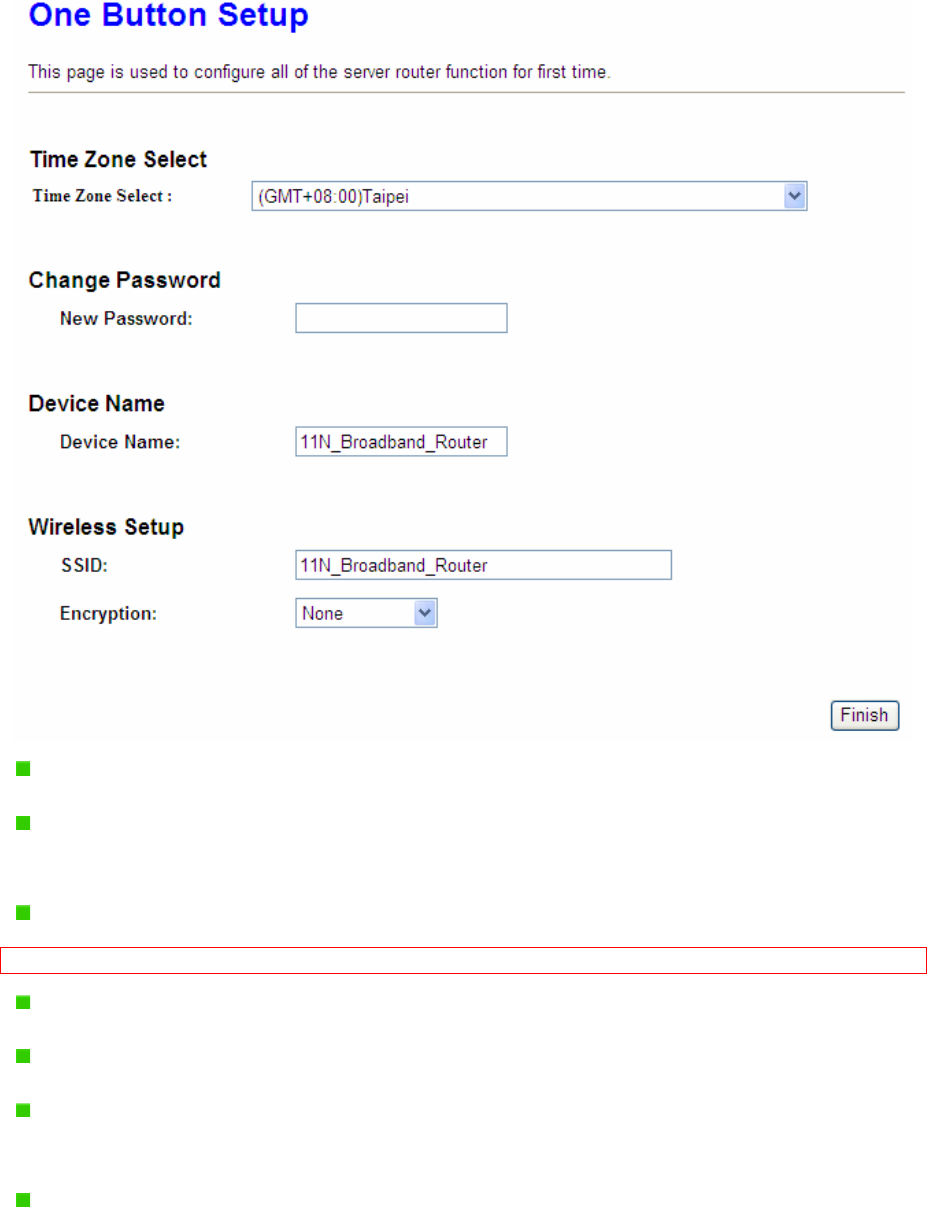
Chapter 3 One Button Setup
The advanced One Button Setup provides users a simple way to set up the complicated
network. Instead of numbers of IPs to be memorized, you just need to fill in some necessary
information and then enjoy the secured internet by clicking the “Finished” button.
3.1 One Button Setup configuration for Router Mode
Step 1. Please switch to Router mode and plug in power.
The default UPnP of 11N Mini Broadband Router is ON.
Version 1.0.15
21
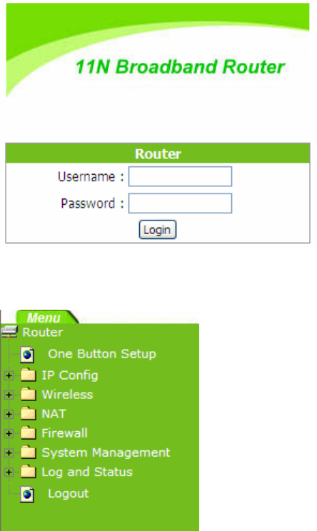
Step 2. Click the Internet Gateway Device to open the login page.
Step 3. Click One Button Setup on the left of the main menu under router mode.
Version 1.0.15
22
Time Zone Select: Select your time zone from the Time Zone drop-down list.
Change Password: For changing password, please fill the password information into
the blank.
Device Name: Name your device here. The default is 11N_Mini_Router.
Note: System will automatically copy the last 6 numbers of this device’s MAC address after your device name.
WAN Interface Setup: Select the WAN Interface from the drop-down list.
WAN Type Setup: Please choose the access type.
Wireless Setup: Fill in the ESSID if it is blank, and your prefer Encryption type. The
default is 11N_Mini_Router.
Finished: Click finished button to complete the setting.
3.2 One Button Setup configuration for AP Mode
Version 1.0.15
23
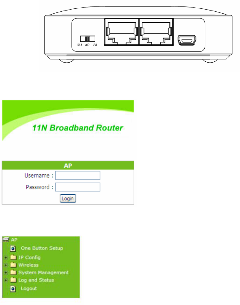
Step 1. Please switch to AP mode and plug in power.
Step 2. Click the Internet Gateway Device to open the login page.
Step 3. Click One Button Setup on the left of the main menu under AP mode.
Version 1.0.15
24
Time Zone Select: Select your time zone from the Time Zone drop-down list.
Change Password: For changing password, please fill the password information into
the blank.
Device Name: Name your device here. The default is 11N_Mini_Router.
Note: System will automatically copy the last 6 numbers of this device’s MAC address after your device name.
Wireless Setup: Define the SSID, and Encryption type.
Finished: Please click finished button to complete the setting.
3.3 One Button Setup configuration for WiFi AP Mode
Step 1. Please switch to WiFi AP mode and plug in power.
Version 1.0.15
25
Step 2. Click the Internet Gateway Device to open the login page.
Step 3. Click One Button Setup on the left of the main menu under WiFi AP mode.
Version 1.0.15
26
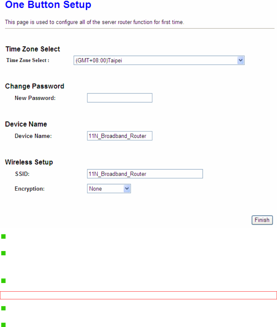
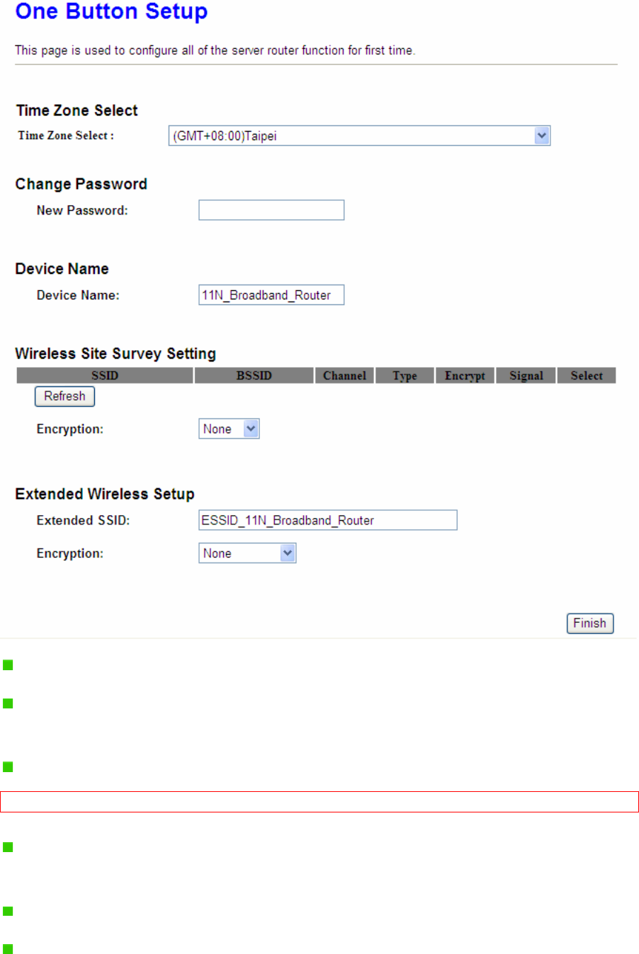
Time Zone Select: Select your time zone from the Time Zone drop-down list.
Change Password: For changing password, please fill the password information into
the blank.
Device Name: Name your device here. The default is 11N_Mini_Router.
Note: System will automatically copy the last 6 numbers of this device’s MAC address after your device name.
Wireless Site Survey Setting: Select the preferred AP for connection, and the
encryption type.
Extended Wireless Setup: Define the ESSID, and Encryption type.
Finished: Please click finished button to complete the setting.

Version 1.0.15
27
Note: One Button Setup is not completed unless users finish all settings and click Finished button.
Version 1.0.15
28
Chapter 4 Basic Setup
4.1 Router Mode
Under Router Mode, the 11n Mobile Router provides a Router/AP function. User can get IP
address assigned by ISP wired or wirelessly. It also supports NAT and DHCP functions that
enable multiple computers to share an Internet connection at the same time.
4.1.1 Switch to Router Mode
Switch to AP mode and plug in power.
Note: 1. Before sliding the switch modes, please power-off the router firstly. Moreover, please stay over 10
seconds between power-off / power-on condition.
2. Switching the mode while power is on will make the router crush, and cause the hardware damage and
information lost.
4.1.2 Administrator Setup Instruction
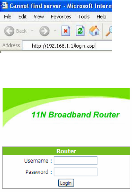
Make sure to switch the mode into Router Mode, then open a Microsoft Internet Explorer,
Mozilla Firefox or Apple Safari browser, and enter http://192.168.1.1 (Default Gateway) into
browser’s blank.
Note: If the homepage doesn’t appear, please check if the TCP/IP configuration is obtaining IP address
automatically or not. If you don’t know how to do it, please refer to “1.5 Get your IP Automatically &
Manually”.
Version 1.0.15
29
The default values for User Name and Password are admin (all in lowercase letters). Click
Login to enter.
4.2 AP Mode
Under AP Mode, the 11N Mini Broadband Router supports 2 LAN ports as Bridge, and user
can connect to this Router via LAN port and provide the lower level wired or wireless internet
connections. NAT function is disabled under AP mode. The 11N Mini Broadband Router
connects the upper level device only through the Ethernet port and gets its assigned IP
address. If not, the 11N Mini Broadband Router will use the default IP or assigned by the
user.
4.2.1 Switch to AP Mode
Switch to AP mode and plug in power.
Version 1.0.15
30
Note: 1. Before sliding the switch modes, please power-off the router firstly. Moreover, please stay over 10
seconds between power-off / power-on condition.
2. Switching the mode while power is on will make the router crush, and cause the hardware damage and
information lost.
4.3 WiFi AP Mode
As WiFi AP Mode, 11N Mini Broadband Router will be a bridge and support a wireless LAN.
NAT function is disabled under WiFi AP mode. The 11N Mini Broadband Router connects
the upper level device wirelessly and gets its assigned IP address. If not, the 11N Mini
Broadband Router will use the default IP or assigned by the user.
4.3.1 Switch to WiFi AP Mode
Switch to WiFi AP mode and plug in power.
Note: 1. Before sliding the switch modes, please power-off the router firstly. Moreover, please stay over 10
seconds between power-off / power-on condition.
2. Switching the mode while power is on will make the router crush, and cause the hardware damage and
information lost.
Version 1.0.15
31
Chapter 5 Advanced Configuration for Router Mode
5.1 IP Configuration
This function allows you to add routing rules into 11N Mini Broadband Router . It is useful if
you connect several computers behind 11N Mini Broadband Router to share the same
connection to Internet.
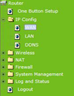
5.1.1 WAN
Select WAN under the IP Config menu. 11N Mini Broadband Router supports 3 interfaces
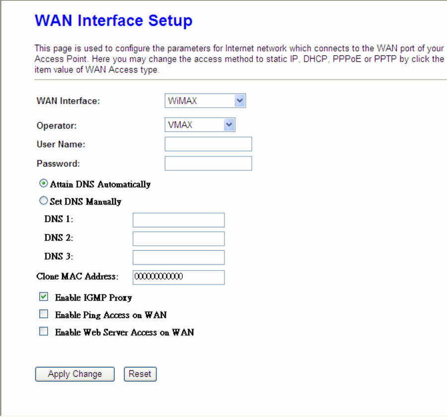
and 4 access types. Follow the instructions below for each to set up accordingly.
Choose your WAN Interface and WAN type, and click Next, its associated settings will show
up.
Version 1.0.15
32

Version 1.0.15
33
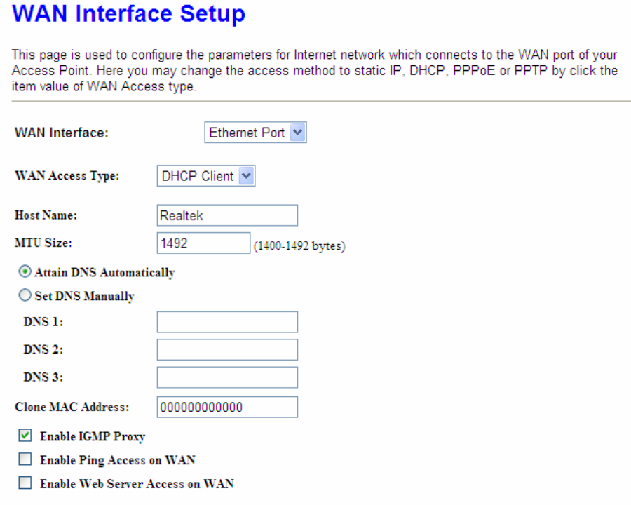
5.1.1.1 WAN Interface– Ethernet Port
If you are using an Ethernet cable to connect the Internet, please select Ethernet port.
Version 1.0.15
34
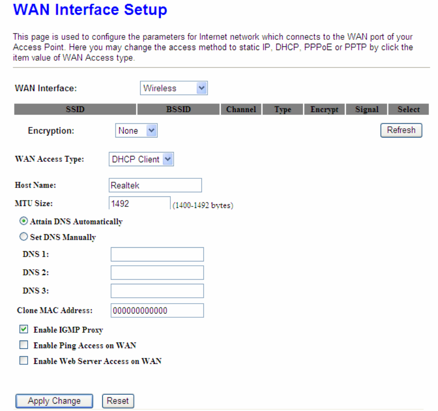
5.1.1.2 WAN Interface– Wireless
If you are connecting the internet via wireless, please select Wireless and its associated
settings will show up underneath at the same time.
You can see a list of available Wireless networks. Select you preferred one to connect and
the Encryption type form the drop-down list.
Version 1.0.15
35
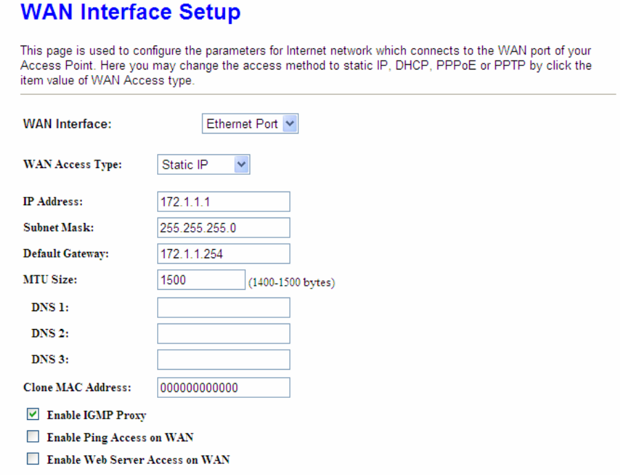
5.1.1.3 WAN Access Type – Static IP
If you applied for a Static IP connection type from ISP, please follow the steps to set up your
WAN connection.
Version 1.0.15
36
1. IP Address
Input your IP Address supplied by ISP. If you don’t know, please check with your ISP.
2. Subnet Mask
Input Subnet Mask, normally it is 255.255.255.0.
3. Default Gateway
Input ISP Default Gateway Address. If you don’t know, please check with your ISP.
4. MTU Size
MTU stands for Maximum Transmission Unit. For Static IP connection, the default MTU
should be provided by computer operating systems (OS). Advanced users can set the MTU
manually for increasing the internet performance. The largest number allowed by Ethernet at
the network layer is 1500 byte
5. DNS
If ISP provides you DNS information, please select Attain DNS automatically, otherwise
Version 1.0.15
37
select Set DNS Manually and input the DNS information into the blank.
6. Clone MAC Address
Copy the MAC address from the device you had registered to your ISP if your ISP asks for
the specific MAC Address.
7. Enable IGMP Proxy
The Internet Group Management Protocol (IGMP) is a communication protocol used to
manage the membership of Internet Protocol multicast groups. IGMP is used by IP hosts and
adjacent multicast routers to establish multicast group memberships. You can choose to
enable IGMP Proxy to provide service.
8. Enable Ping Access on WAN
Select Enable Ping Access on WAN, will make WAN IP address response to any ping
request from Internet users. It is a common way for hacker to ping public WAN IP address, to
see is there any WAN IP address available.
9. Enable Web Server Access on WAN
This option is to enable Web Server Access function on WAN.
10. Apply Changes & Reset
Click on Apply Changes to save the setting data. Or you may click on Reset to clear all the
input data.
5.1.1.4 WAN Access Type – Dynamic IP
If your WAN access type is Dynamic IP, please complete the settings as following
instructions.

Version 1.0.15
38
1. Host Name
The host name is optional; but if your ISP requires you to input a specific host name, please
put it in, for example, 11N Mini Broadband Router applied from ISP. Generally, Cable
Modem will provide the hostname information.
2. MTU Size
MTU stands for Maximum Transmission Unit. For Static IP connection, the default MTU
should be provided by computer operating systems (OS). Advanced users can set the MTU
manually for increasing the internet performance. The largest number is 1492 byte
3. DNS
If ISP provides you DNS information, please select Attain DNS automatically, otherwise
select Set DNS Manually and input the DNS information into the blank.
4. Clone MAC Address
Copy the MAC address from the device you had registered to your ISP if your ISP asks for
the specific MAC Address.
Version 1.0.15
39
5. Enable IGMP Proxy
The Internet Group Management Protocol (IGMP) is a communication protocol used to
manage the membership of Internet Protocol multicast groups. IGMP is used by IP hosts and
adjacent multicast routers to establish multicast group memberships. You can choose to
enable IGMP Proxy to provide service.
6. Enable Ping Access on WAN
Select Enable Ping Access on WAN, will make WAN IP address response to any ping
request from Internet users. It is a common way for hacker to ping public WAN IP address, to
see is there any WAN IP address available.
7. Enable Web Server Access on WAN
This option is to enable Web Server Access function on WAN.
8. Apply Changes & Reset
Click on Apply Changes to save the setting data. Or you may click on Reset to clear all the
input data.
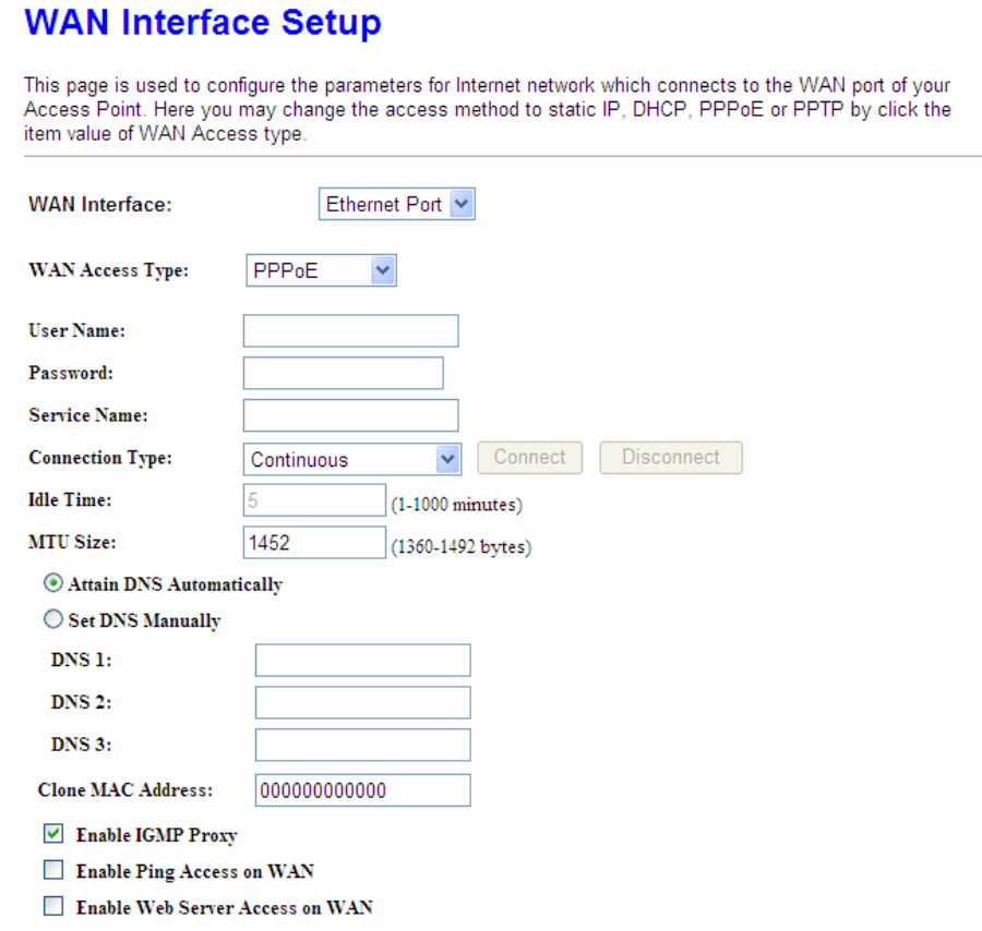
5.1.1.5 WAN Access Type – PPPoE
If you applied for a PPPoE connection type from ISP, please follow the steps to set up your
WAN connection.
Version 1.0.15
40
1. User Name
Input your user name supplied by ISP. If you don’t know, please check with your ISP.
2. Password
Input your Password supplied by ISP.
3. Service Name
Input the service name supplied by ISP.
4. Connection Type
It has three types: Continuous, Connect on Demand, and Manual.
5. Idle Time
It is the time of inactivity before disconnecting your PPPoE session. Enter an Idle Time (in
Version 1.0.15
41
minutes) to define a maximum period of time for which the Internet connect is maintained
during inactivity. If the connection is inactive for longer than the defined Idle Time, then the
connection will be dropped. Either set this to zero or enable Auto-reconnect to disable this
feature.
6. MTU Size
MTU stands for Maximum Transmission Unit. For PPPoE connection, the default MTU should
be provided by computer operating systems (OS). Advanced users can set the MTU
manually for increasing the internet performance. The largest number allowed by Ethernet at
the network layer is 1492 byte
7. DNS
If ISP provides you DNS information, please select Attain DNS automatically, otherwise
select Set DNS Manually and input the DNS information into the blank.
8. Clone MAC Address
Copy the MAC address from the device you had registered to your ISP if your ISP asks for
the specific MAC Address.
9. Enable IGMP Proxy
The Internet Group Management Protocol (IGMP) is a communications protocol used to
manage the membership of Internet Protocol multicast groups. IGMP is used by IP hosts and
adjacent multicast routers to establish multicast group memberships. You can choose to
enable IGMP Proxy to provide service.
10. Enable Ping Access on WAN
Select Enable Ping Access on WAN, will make WAN IP address response to any ping
request from Internet users. It is a common way for hacker to ping public WAN IP address, to
see is there any WAN IP address available.
11. Enable Web Server Access on WAN
This option is to enable Web Server Access function on WAN.
12. Apply Changes & Reset
Click on Apply Changes to save the setting data. Or you may click on Reset to clear all the
input data.
Version 1.0.15
42
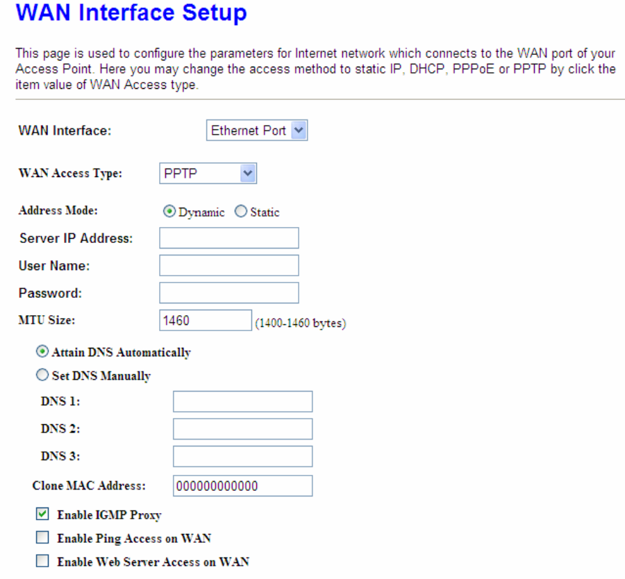
5.1.1.6 WAN Access Type – PPTP
If you have applied for a PPTP connection type from ISP, please follow the steps to set up
your WAN connection.
1. IP Address
Input your IP Address supplied by ISP. If you don’t know, please check with your ISP.
2. Subnet Mask
Input Subnet Mask, normally it is 255.255.255.0.
3. Server IP Address
Input your Server IP Address supplied by ISP. If you don’t know, please check with your ISP.
4. User Name
Version 1.0.15
43
Input the PPTP Account supplied by ISP, for example. If you don’t know, please check with
your ISP.
5. Password
Input the Password supplied by ISP.
6. MTU Size
MTU stands for Maximum Transmission Unit. For PPPoE connection, the default MTU should
be provided by computer operating systems (OS). Advanced users can set the MTU
manually for increasing the internet performance. The largest number allowed is 1460 byte
7. Request MPPE Encryption
Microsoft Point-to-Point Encryption (MPPE) encrypts data in Point-to-Point Protocol
(PPP)-based dial-up connections or Point-to-Point Tunneling Protocol (PPTP) virtual private
network (VPN) connections. 128-bit key (strong), 56-bit key, and 40-bit key (standard) MPPE
encryption schemes are supported. MPPE provides data security for the PPTP connection
that is between the VPN client and the VPN server.
8. DNS
If ISP provides you DNS information, please select Attain DNS automatically, otherwise
select Set DNS Manually and input the DNS information into the blank.
9. Clone MAC Address
Copy the MAC address from the device you had registered to your ISP if your ISP asks for
the specific MAC Address.
10. Enable IGMP Proxy
The Internet Group Management Protocol (IGMP) is a communications protocol used to
manage the membership of Internet Protocol multicast groups. IGMP is used by IP hosts and
adjacent multicast routers to establish multicast group memberships. You can choose to
enable IGMP Proxy to provide service.
11. Enable Ping Access on WAN
Select Enable Ping Access on WAN, will make WAN IP address response to any ping
request from Internet users. It is a common way for hacker to ping public WAN IP address, to
see is there any WAN IP address available.
12. Enable Web Server Access on WAN
Version 1.0.15
44
This option is to enable Web Server Access function on WAN.
13. Apply Changes & Reset
Click on Apply Changes to save the setting data. Or you may click on Reset to clear all the
input data.
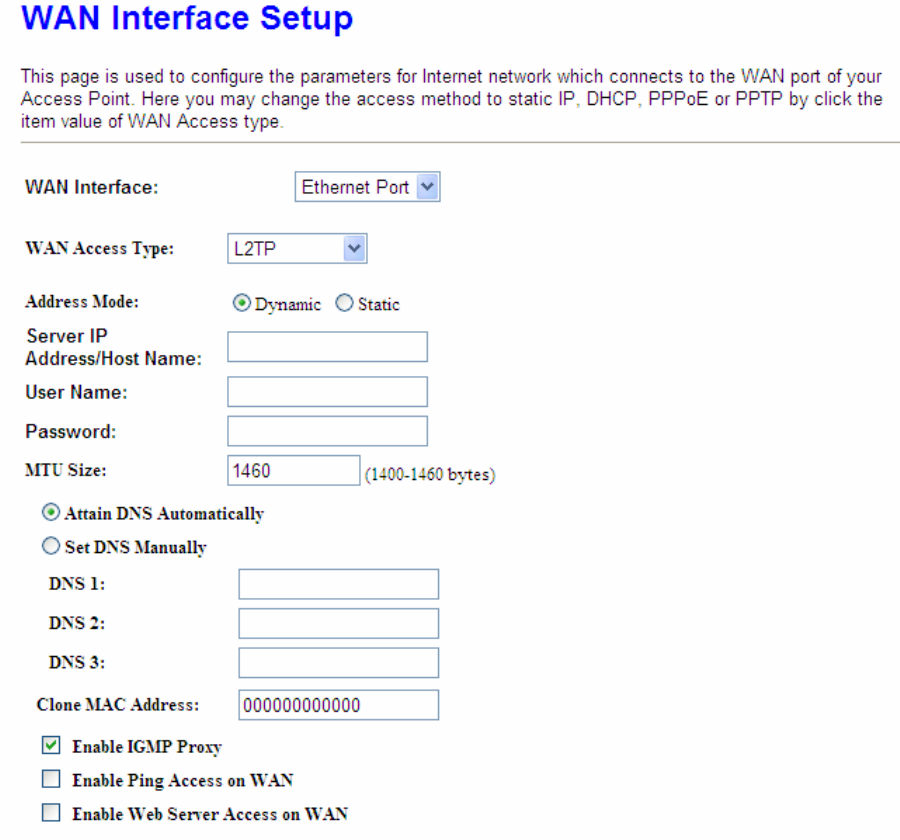
5.1.1.7 WAN Access Type – L2TP
If you have applied for a L2TP connection type from ISP, please follow the steps to set up
your WAN connection.
1. Server IP Address
Version 1.0.15
45
Input your Server IP Address supplied by ISP. If you don’t know, please check with your ISP.
2. User Name
Input the L2TP Account.
3. Password
Input the Password.
4. MTU Size
MTU stands for Maximum Transmission Unit. For PPPoE connection, the default MTU should
be provided by computer operating systems (OS). Advanced users can set the MTU
manually for increasing the internet performance. The largest number allowed is 1460 byte
5. DNS
If ISP provides you DNS information, please select Attain DNS automatically, otherwise
select Set DNS Manually and input the DNS information into the blank.
6. Clone MAC Address
Copy the MAC address from the device you had registered to your ISP if your ISP asks for
the specific MAC Address.
7. Enable IGMP Proxy
The Internet Group Management Protocol (IGMP) is a communications protocol used to
manage the membership of Internet Protocol multicast groups. IGMP is used by IP hosts and
adjacent multicast routers to establish multicast group memberships. You can choose to
enable IGMP Proxy to provide service.
8. Enable Ping Access on WAN
Select Enable Ping Access on WAN, will make WAN IP address response to any ping
request from Internet users. It is a common way for hacker to ping public WAN IP address, to
see is there any WAN IP address available.
9. Enable Web Server Access on WAN
This option is to enable Web Server Access function on WAN.
10. Apply Changes & Reset
Click on Apply Changes to save the setting data. Or you may click on Reset to clear all the
input data.
Version 1.0.15
46
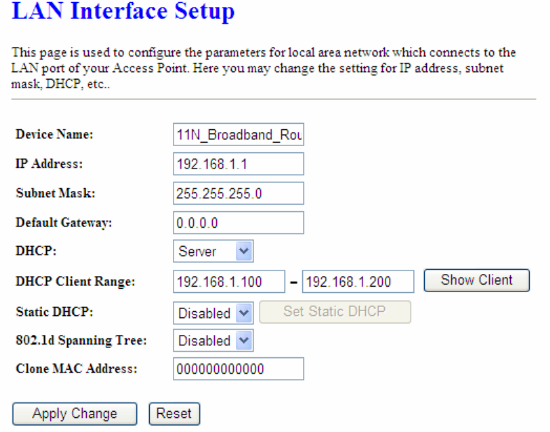
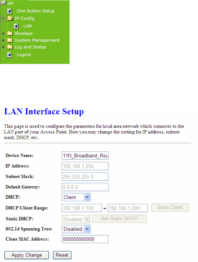
5.1.2 LAN Interface Setup
Use this page to set up the local IP address and subnet mask for your router. Please select
LAN Interface Setup under the IP Config menu and follow the instructions below to enter
the LAN setting page to configure the settings you want.
1. IP Address
The default value of LAN IP address is 192.168.1.1 for this router.
2. Subnet Mask
Input Subnet Mask, normally it is 255.255.255.0.
3. Default Gateway
Input ISP Default Gateway Address. If you don’t know, please check with your ISP.
4. DHCP
Enable or disable DHCP services. The DHCP server will automatically allocate an unused IP
address from the IP address pool to the requesting computer if enabled.
Version 1.0.15
47
5. DHCP Client Range
Define the DHCP client range and then the DHCP server will assign an IP to the requesting
computer from this range. The Show Client will display every assigned IP address, MAC
address, and expired time. The default range is 192.168.1.100 - 192.168.1.200.
6. 802.1d Spanning Tree
IEEE 802.1d Spanning Tree Protocol (STP) is a link layer network protocol that ensures a
loop-free topology for any bridged LAN. The main purpose of STP is to ensure that you do not
create loops when you have redundant paths in your network. Loops are deadly to a network.
7. Clone MAC Address
Copy the MAC address from the device you had registered to your ISP if your ISP asks for
the specific MAC Address.
8. Apply Changes & Reset
Click on Apply Changes to save the setting data. Or you may click on Reset to clear all the
input data.
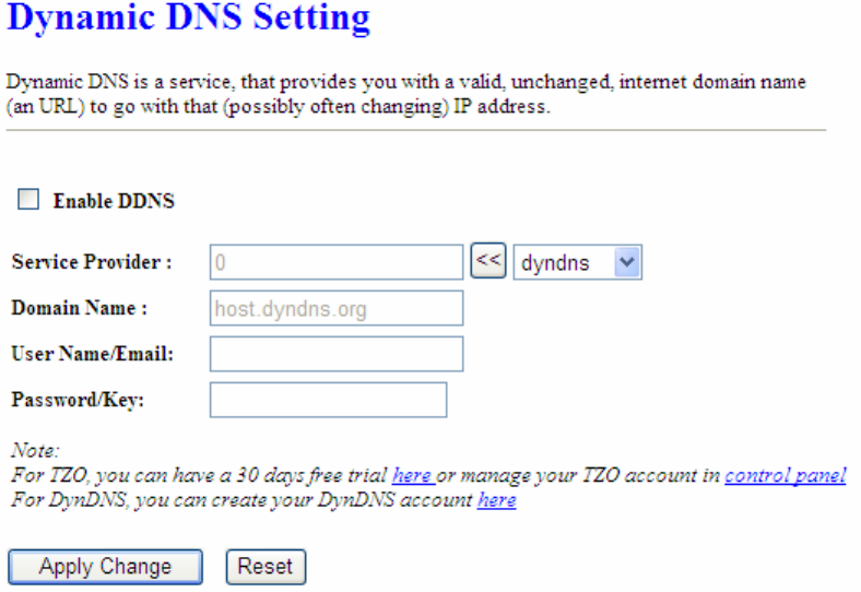
5.1.3 Dynamic DNS Setting
Dynamic DNS allows you to make an assumed name as a dynamic IP address to a static
hostname. Please configure the dynamic DNS below. Please select DDNS under the IP
Config menu, and follow the instructions below to enter the DDNS setting page to configure
the settings you want.
Version 1.0.15
48
1. Enable / Disable DDNS
Select enable to use DDNS function. Each time your IP address to WAN is changed, and the
information will be updated to DDNS service provider automatically.
2. Service Provider
Choose correct Service Provider from drop-down list, here including DynDNS, TZO,
ChangeIP, Eurodns, OVH, NO-IP, ODS, Regfish embedded in 11N Mini Broadband Router .
3. Domain Name
This field represents the host name you register to Dynamic-DNS service and expect to
export to the world.
4. User Name /Email
User name is used as an identity to login Dynamic-DNS service.
5. Password /Key
Password is applied to login Dynamic-DNS service.
6. Apply & Cancel
Click on Apply button to continue. Click on Cancel button to clear the setting on this page.
Version 1.0.15
49
5.2 Wireless Setup
11N Mini Broadband Router enables fastest 300 Mbps IEEE802.11g wireless transmissions
and keeps compatibility with existing IEEE 802.11n devices. 11N Mini Broadband Router
complies with IEEE 802.11b/g standard. Please select Wireless under the main menu.
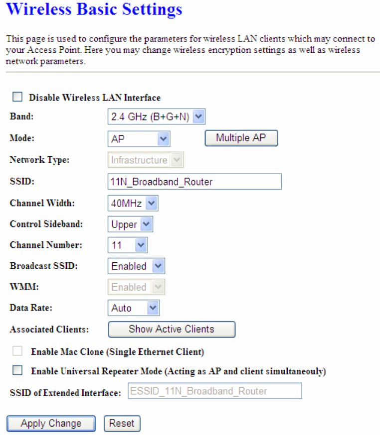
5.2.1 Wireless Basic Settings
Follow the instructions to configure the Wireless settings.
Version 1.0.15
50
1. Disable Wireless LAN Interface
Select Disable Wireless LAN Interface to turn off the wireless function.
2. Band
This field indicates the 802.11x interface mode. For example, “2.4GHz(G)” prevents the
802.11b clients from accessing the router. “2.4GHz(B+G)” allows both 802.11b and 802.11g
clients to access the router. There are 6 options, 2.4 GHz (B/G/N/B+G/G+N/B+G+N) from the
drop down list.
3. Mode
Select AP, WDS, or AP+WDS to allow or disallow the wireless operation.
Version 1.0.15
51
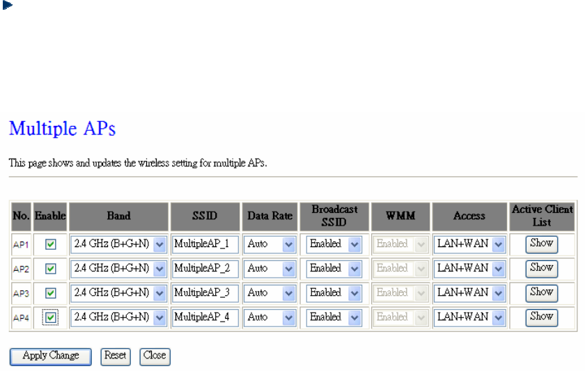
Multiple APs
Click Multiple APs to set up 4 different SSIDs to deploy a shared WLAN. Users can add
or limit the properties for each SSID, increasing the flexibility and efficiency of the
network.
(1.) Enable: check it for enable or not.
(2.) Band: select the frequency from the drop down list.
(3.) SSID: please enter different SSID in each class.
(4.) Data Rate: please select the data transmission rate.
(5.) Access: defined the access type.
a. LAN+WAN: the client can access to the Internet and connect to 11N Mobile
router’s GUI to setup.
b. WAN: the client can only access to the Internet.
(6.) Active Client List: display the properties of the client which is connecting
successfully.
(7.) Apply Changes: Please click Apply Changes to initiate or click Reset to cancel.
4. Network Type:
Please select “Infrastructure” or “Ad hoc.” The default is “Infrastructure.” The selection is
disabled when wireless mode is selected to AP.
5. SSID:
Please input your wireless network name. Default is “11N_Mini_Router”.

Version 1.0.15
52
6. Channel Width
Please select “20MHZ” or “40MHZ” channel width to change the transmission channels.
7. ControlSideband
Setting the Sideband "Upper" or "lower.”
8. Channel Number
Please select your wireless network channel. There are Auto, 2~11.
9. Broadcast SSID
Enable or disable the SSID broadcast function. Disable this feature can provide more security
of your WLAN.
10. Data Rate
Rate at which data can be communicated (bps); auto, 1M, 2M, 5.5M, 11M, 6M, 9M, 12M, 18M,
24M, 36M, 48M or 54M to be selected from the drop-down list.
11. Associated Clients
Check the WiFi ISP connectors and the connecting status.
12. Enable Mac Clone (Single Ethernet Client)
Copy the MAC Address for identity of some ISPs.
13. Enable Universal Repeater Mode (Acting as AP and Client simultaneously)
Enable Universal Repeater Mode, 11N Mini Broadband Router will act as a wireless AP
and AP client at the same time, and able to link to another AP.. It uses AP client function to
connect to a Root AP (any AP) and uses AP function to service all wireless stations within its
coverage. All the stations within the coverage of 11N Mini Broadband Router can be bridged
to the Root AP. It can help user to extend the coverage of wireless network.
How to Enable URM (Universal Repeater Mode)
User could enable URM in wireless basic setting page as shown in following figures.
Step 1. Get back to menu “Network Config” and write down the SSID, channel and
security.
Step 2. Setting the same SSID, channel and security you got form “Network Config”
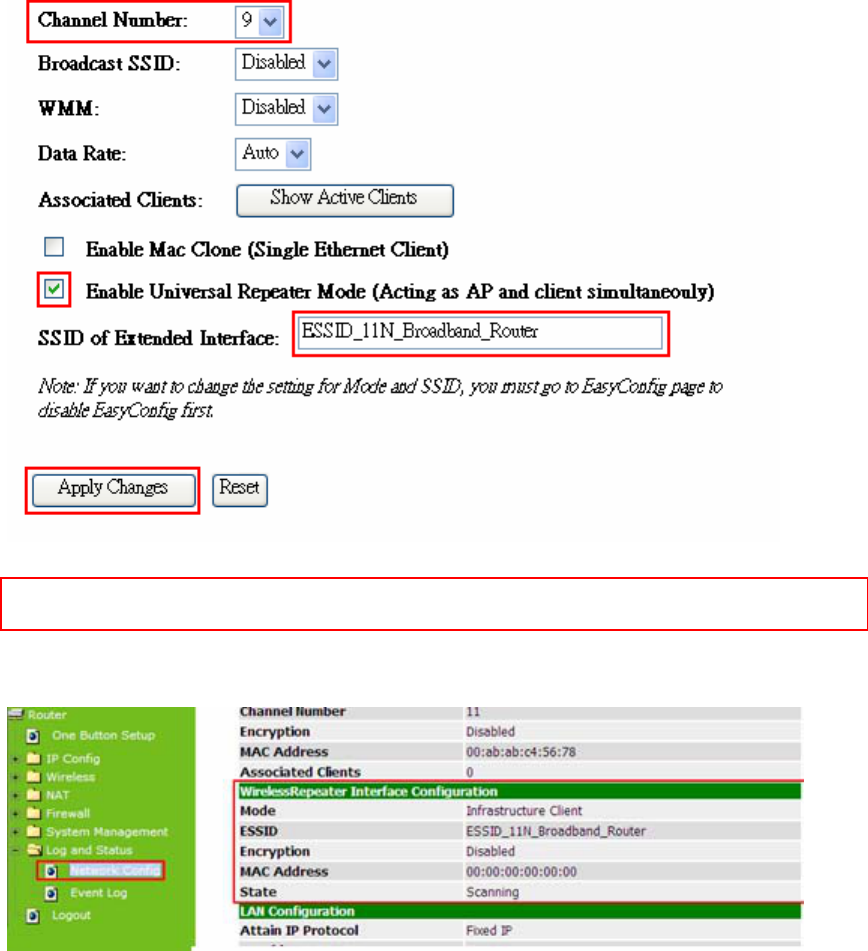
Version 1.0.15
53
and Click on Apply Changes to save the setting
Note: The DHCP server should be disabled under menu “LAN Interface Setup” and then the URM could be
enabled.
Step 3. Check the AP connectors and the Wireless connecting status.
14. SSID of Extended Interface
When mode is set to “AP” and Universal Repeater Mode is enabled, user should input SSID
of another AP (the upper level device) in the field of SSID of Extended Interface.
15. Apply Changes & Reset
Click on “Apply Changes” to save the setting data. Or you may click on “Reset” to clear all
the input data.

Version 1.0.15
54
5.2.2 Wireless Advanced Settings
Please follow the instructions to configure the Wireless settings.
1. Fragment Threshold
To identify the maximum length of packet, the overflow packet length wil be fragmentized.
The allowed range is 256-2364, and default length is 2346 bytes.
2. RTS Threshold
This value should remain at its default setting of 2347. The range is 0~2347. Should you
encounter inconsistent data flow, only minor modifications are recommended. If a network
packet is smaller than the present RTS threshold size, the RTS/CTS mechanism will not be
enabled. The router sends Request to Send (RTS) frames to a particular receiving station
and negotiates the sending of a data frame. After receiving an RTS, the wireless station
responds with a Clear to Send (CTS) frame to acknowledge the right to begin transmission.
Fill the range from 0 to 2347 into this blank.
3. Beacon Interval
Beacons are packets sent by an access point to synchronize a wireless network. Specify a
beacon interval value. The allowed setting range is 20-1024 ms.
Version 1.0.15
55
4. Preamble Type
The preamble (also called “a header”) is a section of data at the head of a packet that
contains information that wireless devices need when they send and receive packets. Short
preambles improve throughput performance, but some wireless devices require long
preambles. Select the suitable preamble as short or long preamble.
5. IAPP
Inter Access Point Protocol. Allow seamless roaming between Access Points in your
wireless network. Coupled with superior RF performance
6. Protection
Select to enable the wireless protection or not.
7. Aggregation
Data aggregation can reduce the amount of data routed through the network, and increasing
throughput.
8. Short GI
Enabling the Short Guard Interval increases the wireless transmission.
9. RF Output Power
User can adjust the RF output power to get the best wireless connection. There are 5 power
types available: 100%, 70%, 50%, 35%, and 15%.
10. Apply Changes & Reset
Click on “Apply Changes” to save the setting data. Or you may click on “Reset” to clear all the
input data.
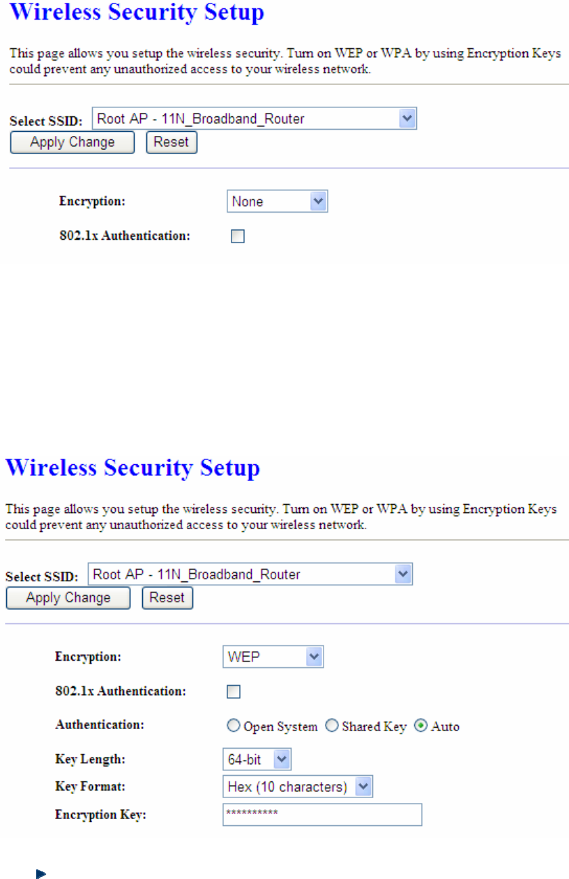
5.2.3 Wireless Security Setup
4 encryption types can be selected here, please follow the instructions below for each.
Version 1.0.15
56
1. Encryption – WEP
Enabling WEP can protect your data from eavesdroppers. If you do not need this feature,
select “None” to skip the following setting. 11N Mini Broadband Router supports both 64-bit
and 128-bit encryption using the Wired Equivalent Privacy (WEP) algorithm. Select the type
of encryption you want to use (64 or 128 bit) and configure one to four WEP Keys. The
“1280bit” method is more secure than the “64-bit”.
802.1x Authentication
Enable 802.1x Authentication so that a wireless node must be authenticated before it
can gain access to other LAN resources.
Version 1.0.15
57
Key Length: For 64bits WEP key, either 5 ASCII characters or 10 hexadecimal digitals
leading by 0x can be entered. For 128bits WEP key, either 13 ASCII characters or 26
hexadecimal digits leading by 0x can be entered.
Note: 128 bits WEP is most secure, but has more encryption/decryption overhead. Note that all wireless devices
must support the same WEP encryption bit size and have the same key. Four keys can be entered here, but
only one key can be selected at a time. The keys can be entered in ASCII or Hexadecimal. Select the item
from drop-down list you wish to use.
Encryption Key: At most four keys can be set. A WEP key is either 10 or 26
hexadecimal digits (0~9, a~f, and A~F) based on whether you select 64 bit or 128 bit in
the WEP drop-down list.
2. Encryption – WPA (WPA, WPA2 & WPA2 Mixed)
The WPA, WPA2 & WPA2 Mixed encrypt each frame transmitted from the radio using the
pre-shared key (PSK) which entered from this panel or a key got dynamically through 802.1x.
WPA Authentication Mode
Enterprise (RADIUS): Please input the port, IP address, and password of
authentication RADIUS Server.
Personal (Pre-Shared Key): Pre-Shared Key type is coding in ASCII, and the
length is between 8 to 63 characters. If the coding is in Hex, the key length is 64
characters.
3. Apply Changes & Reset
Click on Apply Changes to save the setting data. Or you may click on Reset to clear all the
Version 1.0.15
58
input data.
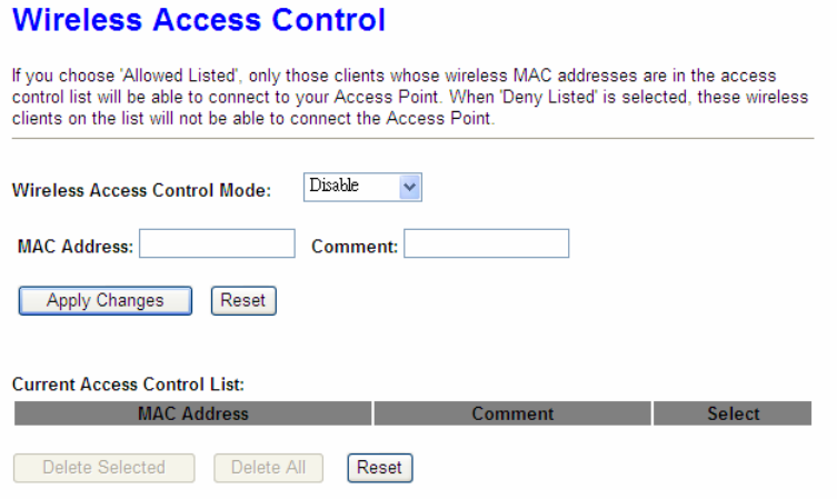
5.2.4 Wireless Access Control
With the MAC address, you may allow or disallow the access to your AP.
1. Wireless Access Control Mode
“Allowed Listed” means only the MAC address listed on the allowed list can access to your
wireless network.
“Deny Listed” means the listed MAC Address are not allowed to link to your wireless
network.
“Disable” for function disuse.
2. MAC Address
Please input the allowed or denied MAC address, for example, 001122334455.
3. Comment
You may input the comments for the set MAC Address.
4. Apply Changes & Reset
Click on “Apply Change” to save the setting data. Or you may click on “Reset” to clear all the
input data.
Version 1.0.15
59
5. Current Access Control List
In this list, all the MAC info you input will be displayed.
6. Delete Selected and Delete All
Click on “Delete Selected” to erase the selected MAC address. Click on “Delete All” to erase
all the entered MAC Address.
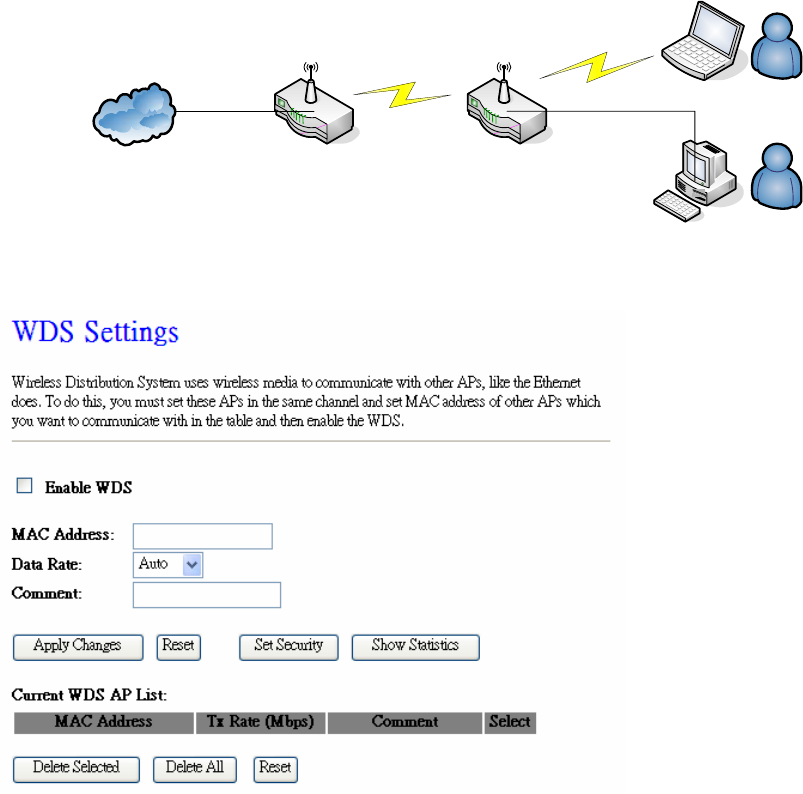
5.2.5 WDS Settings
WDS (Wireless Distribution System) is a Wireless Access Point mode that enables wireless
bridging in which only WDS APs communicate with each other (without allowing for wireless
clients or stations to access them), and/or wireless repeating in which APs communicate both
with each other and with wireless stations (at the expense of half the throughput).
Internet
AP Router
WDS
AP Router
WDS
Wireless Connection
Wired Connection
Please follow the instructions to setup WDS connections.
Version 1.0.15
60
Step 1. Check the MAC address and Channel number of the device you want to setup
WDS with 11N Mini Broadband Router .
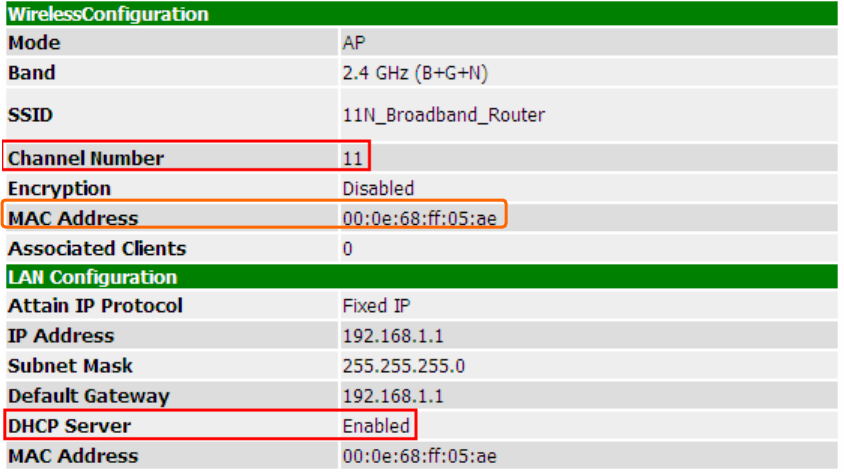
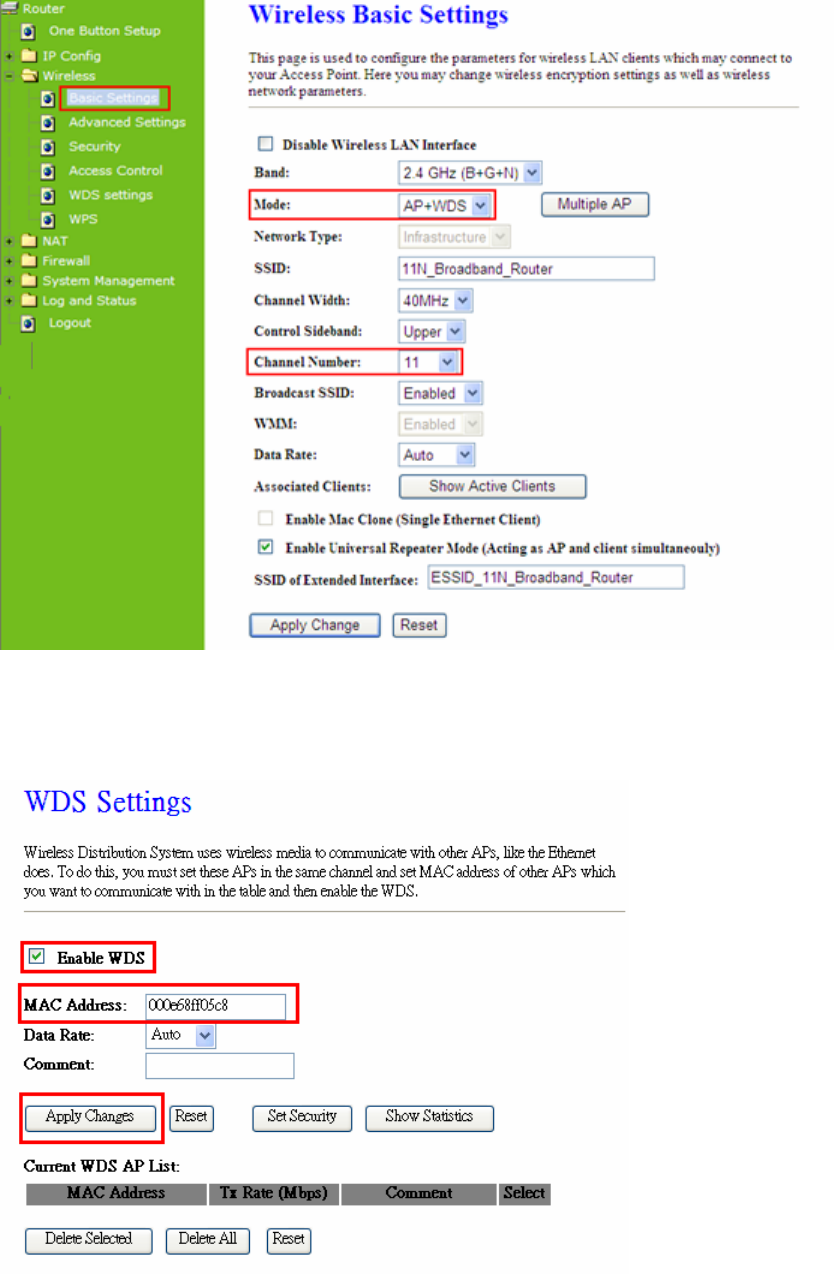
Step 2. Get back to the menu “Wireless Basic Settings” of 11N Mini Broadband Router .
Select AP+WDS mode, and then select the Channel Number. Click Apply Changes to
save the setting data.
Version 1.0.15
61
Step 3. Enter the WDS Settings page, select Enable WDS, and then input the MAC
address of the paired device. Click Apply Changes to save the setting data.
Step 4. When the time counts down to 0, you will see the MAC address of the paired
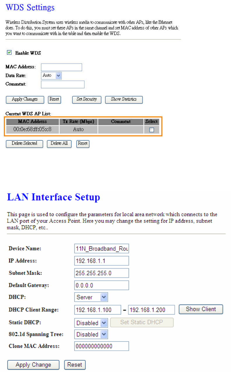
device displaying on Current WDS AP List.
Version 1.0.15
62
Step 5. Head back to LAN Interface, disable DHCP option, and then click Apply Changes
to save the setting data.
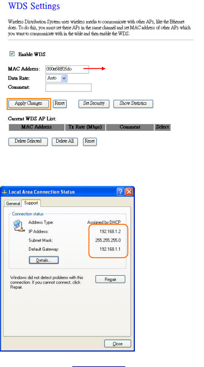
Step 6. Doing the same way to setup the MAC address in the paired device. Launch the
UT to the menu “WDS settings” of the paired device, and input router’s MAC address. Click
Version 1.0.15
63
Apply Changes to save the setting data.
Step 7. After initiating the paired device, please check Local Area Connections. Click
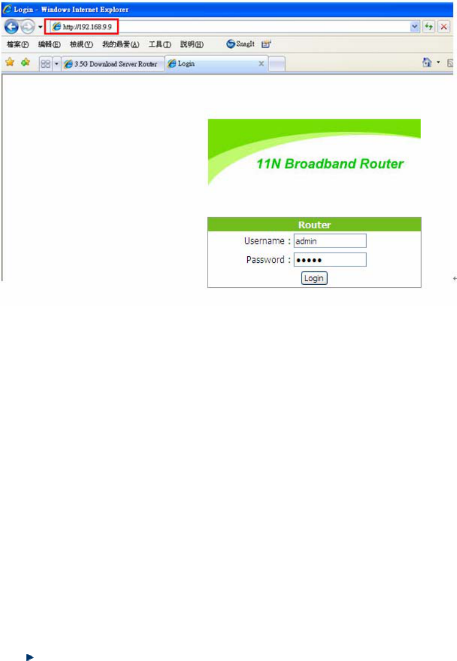
Supports to check out the IP address which is assigned by the paired device.
Step 8. You can input http://192.168.9.9 in IE browser to enter the GUI page of the paired
device and make sure the connection.
Input the MAC address here.
Version 1.0.15
64
5.2.6 WPS
Wi-Fi Protected Setup (WPS) is an easy way to establish a secured wireless network
between 11N Mini Broadband Router and wireless card. Users do not need to manually
entering a creative, yet predictable security key on both Wi-Fi devices to prevent unwanted
access to their wireless network. With WPS, it can automatically configure a wireless network
with a network name (SSID) and strong WPA data encryption and authentication.
WPS can be enabled by 2 methods:
1. PBC (Push button configuration) Method, in which the user simply has to push a
button, either an actual or a virtual one, on both WPS devices to connect.
2. PIN (Personal Identification Number) Method, in which a PIN has to be taken either
from a sticker label or from the web interface of the WPS device. This PIN will then be
entered in the AP or client WPS device to connect.
Please follow instructions below to enable the WPS function.
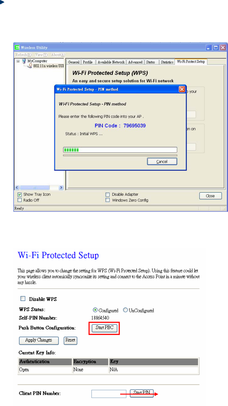
Start PBC:
Version 1.0.15
65
(1.) Press the WPS button from 11N Mini Broadband Router or click Start PBC from
menu “Wi-Fi Protected Setup”, and waiting for the WPS wireless card setting.
or
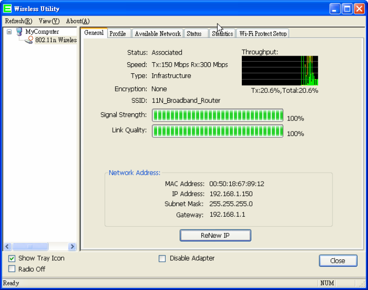
(2.) Open the “Wireless Utility” of your wireless card, and click its “PBC” button, to
start auto pairing.
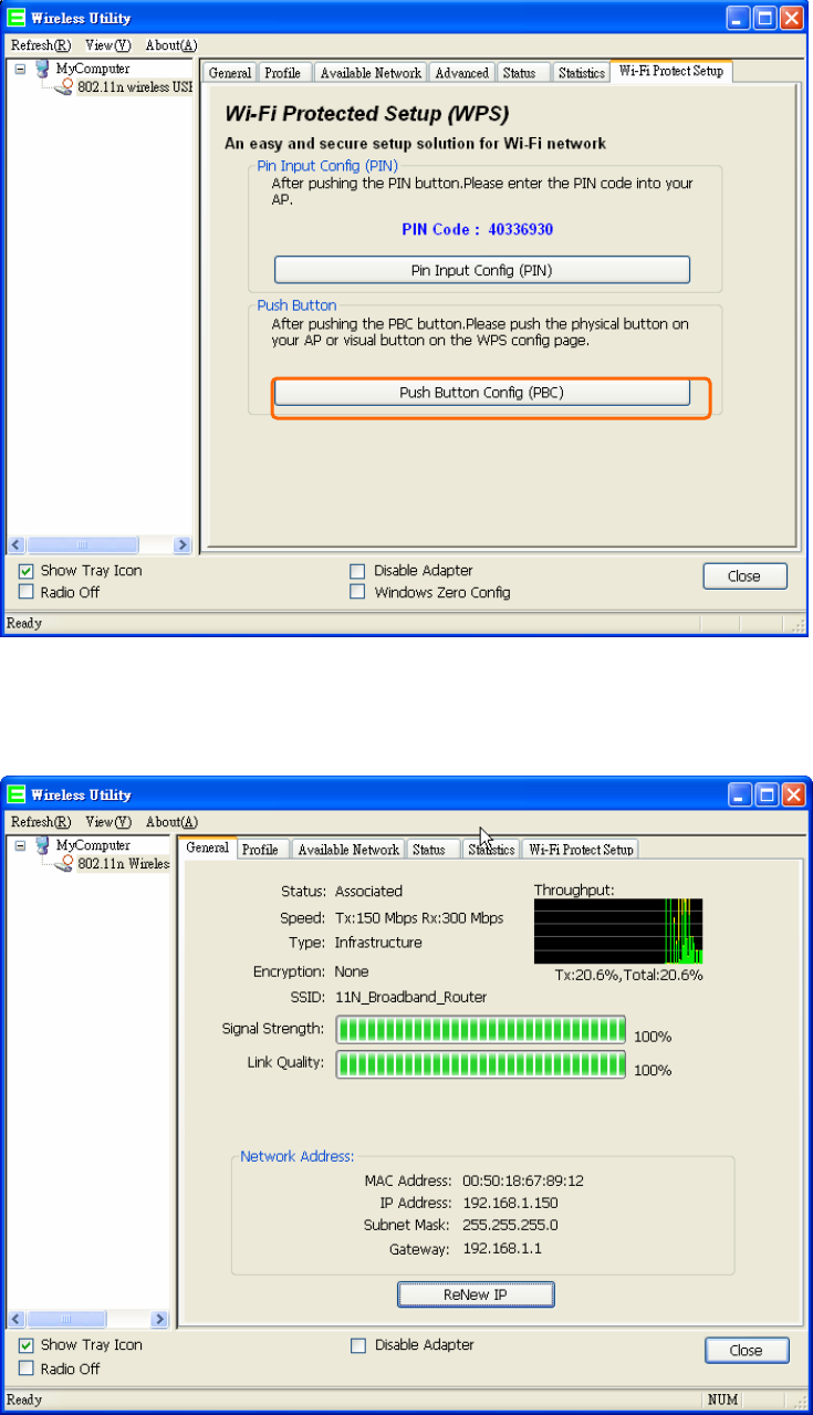
Version 1.0.15
66
(3.) While scanning is successful, the information of the wireless card appears in the
windows below.
Version 1.0.15
67
Start PIN:
(1.) Open the “Wireless Utility” of your wireless card. Follow its PIN instruction to get
a new PIN number. Write it down.
(2.) Open menu “Wi-Fi Protected Setup” of 11N Mini Broadband Router , input the
PIN number from the wireless card then click Start PIN.
Enter the PIN Code you got
from the wireless card.
Version 1.0.15
68
(3.) Back to “Wireless Utility” and press the “Start PIN” button to complete the
auto-paring process.
5.3 NAT
NAT is a method of mapping one or more IP addresses and/or services ports into different
specified services, where NAT stands for Network Address Translation. It allows the internal
IP addresses of many computers on a Local Area Network (LAN) to be translated to one
public address, saving users’ cost. It also plays a security role by obscuring the true IP
addresses of important machines from potential hackers on the Internet. For convenience, we
called a router having the NAT facility as a NAT-enabled router.
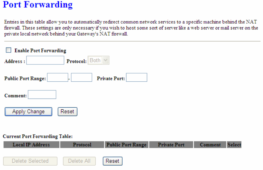
5.3.1 Visual Server
To offer services, like WWW, FTP, provided by a server in your local network accessible for
outside users, you should specify a local IP address to the server. Then, add the IP address
and network protocol type, port number, and name of the service in the following list. Based
on the list, the gateway will forward service request from outside users to the corresponding
local server.
Version 1.0.15
69
1. Enable Port Forwarding
Enable Port Forwarding to allow an external user to reach a port within a private LAN.
2. IP Address
Specify the private IP address of the internal host offering the service.
3. Protocol
Specify the transport layer protocol (TCP or UDP).
4. Port Range
Enter the Start and End ports in the range you'd like to forward. If you're just forwarding 1 port,
set them both equal. For example 80-80 or 20-22。
5. Comment
You can add comments for this port forwarding rule.
6. Apply Changes & Reset
Click on Apply Changes to save the setting data. Or you may click on Reset to clear all the
input data.
7. Current Port Forwarding Table
Version 1.0.15
70
It will display all port forwarding regulation you made.
8. Delete Selected & Delete All
Click Delete Selected will delete the selected item. Click Delete All will delete all items in this
table.
9. Reset
You can click Reset to cancel.
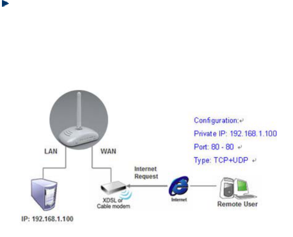
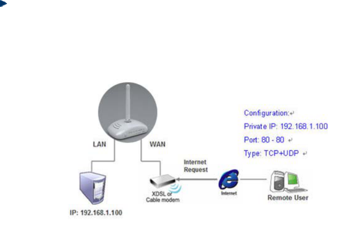
Port Forwarding
The following figure shows the ip forwarding configuration of your web on a local area
network. The web server is located on 192.168.1.100, forwarding port is 80, and type is
TCP+UDP.
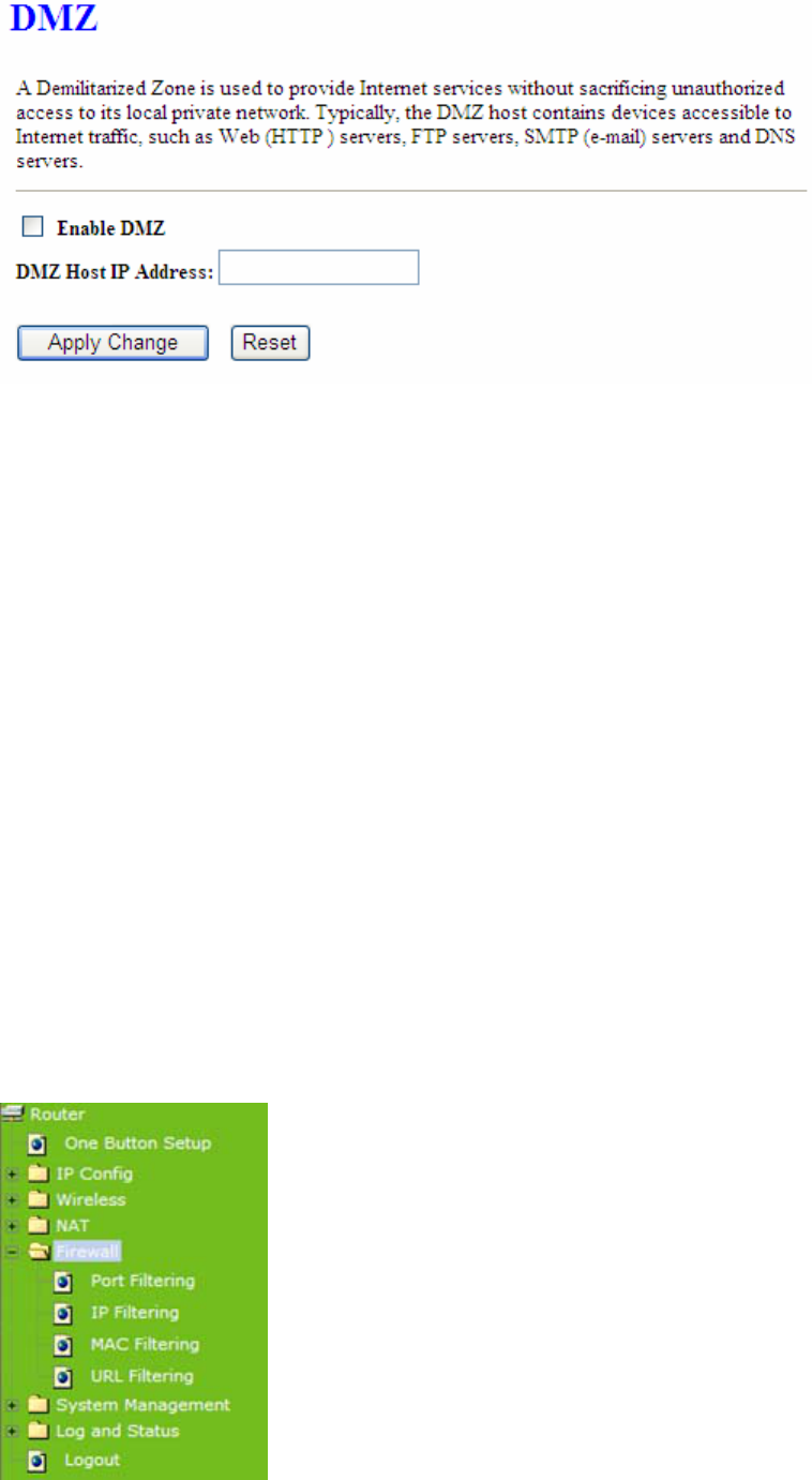
5.3.2 Visual DMZ
Virtual DMZ allows you to expose one computer to Internet, so that all inbound packets will be
redirected to the computer you set. It is useful while you run some applications that use
uncertain incoming ports. Please use it carefully.
Version 1.0.15
71
1. Enable DMZ
Check Enable to apply Virtual DMZ for the Router.
2. DMZ Host IP Address
This field stands for the destination IP address that you like to redirect the matched packet to.
3. Apply Changes & Reset
Click on Apply Changes to save the setting data. Or you may click on Reset to clear all the
input data.
5.4 Firewall
The Firewall function helps to protect your local network against attacks from outside. It also
provides a way of restricting users on the local network from accessing the Internet.
Additionally, it can filter out specific packets to trigger the router to place an outgoing
connection.
Version 1.0.15
72
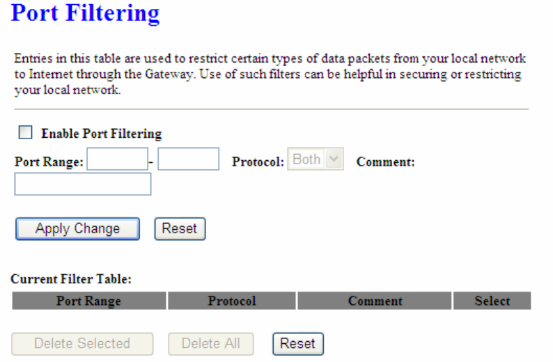
5.4.1 Port Filtering
This function allows users to filter and manage specific ports; to limit the use of certain
applications to transmit through a specific port. Port filtering helps users to improve the
security of your network.
1. Enable Port Filtering
Check Enable Port Filtering to start the service.
2. Port Range
Enter the Start and End ports in the range you'd like them to be filtered.
3. Protocol
Please select the protocol type of the port.
4. Comment
You can add comments for this Port Filtering rule.
5. Apply Changes & Reset
Click on Apply Changes to save the setting data. Or you may click on Reset to clear all the
input data.
6. Current Filter Table
Version 1.0.15
73
It will display all ports that are filtering now.
7. Delete Selected & Delete All
Click Delete Selected will delete the selected item. Click Delete All will delete all items in this
table.
8. Reset
You can click Reset to cancel.
Port Filtering
The following figure shows a user limits some applications to use the 80 port.
*All clients inside the local area network can’t open the 80 port through this router.
5.4.2 IP Filtering
Use IP Filter to deny LAN IP addresses from accessing the Internet. You can deny specific
port numbers or all ports for the specific IP address.
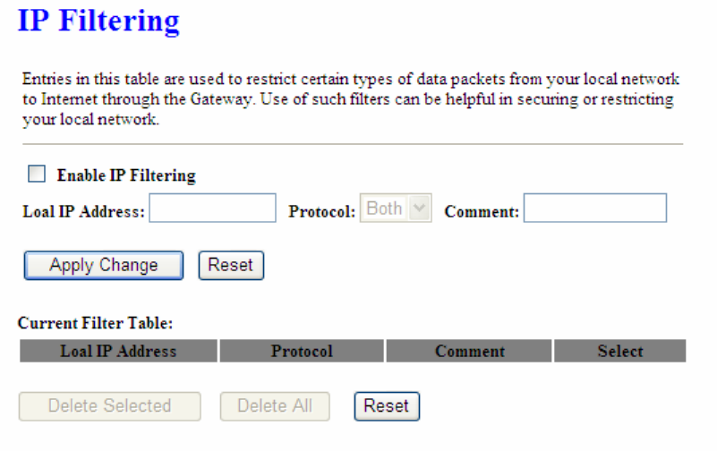
Version 1.0.15
74
1. Enable IP Filtering
Check enable or disable to apply IP Filter function.
2. Local IP Address
Please enter the IP address that needs to be filtered.
3. Protocol
Please select the protocol type of the IP address.
4. Comment
You can add comments for this regulation.
5. Apply Changes & Reset
Click on Apply Changes to save the setting data. Or you may click on Reset to clear all the
input data.
6. Current Filter Table
It will display all IP addresses that are filtering now.
7. Delete Selected & Delete All
Click Delete Selected will delete the selected item. Click Delete All will delete all items in this
table.
8. Reset
Version 1.0.15
75
You can click Reset to cancel.
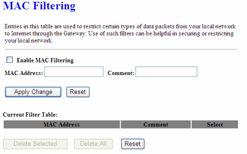
5.4.3 MAC Filtering
Use MAC filters to deny LAN computers by their MAC addresses from accessing the Internet.
You can manually add a MAC address that is currently connected to 11N Mini Broadband
Router .
1. Enable MAC Filtering
Check enable or disable to apply MAC Filter function.
2. MAC Address
Enter the MAC address manually that you want to filter.
3. Comment
You can add comments for this MAC Filtering rule.
4. Apply Changes & Reset
Click on Apply Changes to save the setting data. Or you may click on Reset to clear all the
input data.
5. Current Filter Table
It will display all MAC addresses that are filtering now.
Version 1.0.15
76
6. Delete Selected & Delete All
Click Delete Selected will delete the selected item. Click Delete All will delete all items in this
table.
7. Reset
You can click Reset to cancel.
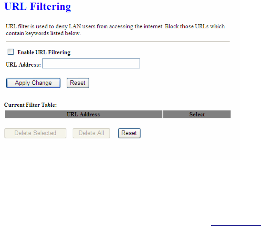
5.4.4 URL Filtering
Keyword based URL (Uniform Resource Locator) filtering allows you to define one or more
keywords that should not appear in URL’s. Any URL containing one or more of these
keywords will be blocked. This is a policy independent feature i.e. it cannot be associated to
ACL rules. This feature can be independently enabled / disabled, but works only if firewall is
enabled.
1. Enable URL Filtering
Check enable or disable to apply URL filter function.
2. URL Address
Enter the URL address into this blank to apply filter blocking, example: “www.yahoo.com.
3. Apply Changes & Reset
Version 1.0.15
77
Click on Apply Changes to save the setting data. Or you may click on Reset to clear all the
input data.
4. Current Filter table
Shows all filtered URL information.
5. Delete Selected & Delete All
Click Delete Selected will delete the selected item. Click Delete All will delete all items in this
table.
6. Reset
You can click Reset to cancel.
Note: URL Filtering cannot work when the Visual Server is enabled. Please disable Visual Server before activate
filter.
5.5 System Management
11N Mini Broadband Router provides system management including password changing,
firmware upgrade, time setting, user’s account setting and other detail settings. Following is
detail explanation for each.
5.5.1 Change Password
Version 1.0.15
78
Users can set or change their password in this section.
1. New Password
Enter the new password you want to change.
2. New Password (Confirm)
Enter the new password again for confirming.
3. Apply & Cancel
Click Apply to continue or Cancel to clear the settings on this page.
Note: 1. Only the password can be changed, the user name for administrator is admin and not to be changed.
2. If you forget administrator’s password, please reset 11N WLAN Mobile Server Router to default setting by
pressing the “Reset” button on the rear panel over 10 seconds. And the password will return to admin.
5.5.2 Upgrade Firmware
There is certain risk while upgrading firmware. Upgrading firmware is not recommended
unless the significant faulty is found. You can upgrade the firmware of 11N Mini Broadband
Router on this page. Make sure the firmware you want to use is on the local hard drive of
the computer. Click Upgrade Firmware to proceed.
Version 1.0.15
79
1. Update Firmware
Click on Browse… button to search your local hard drive and locate the firmware to be
used for update.
2. Upload & Reset:
Click Upload to upgrade the firmware or Reset to restore to factory default Settings
Note: 1. To prevent the firmware upgrading interrupted by other wireless signals and caused failure. We
recommend using wired connection to do the upgrading.
2. Before upgrading the firmware, please remove any USB device which connected with this router.
3. The firmware upgrade will not remove your previous settings.
Reset button:
On the back of this router, there is a reset button. If you can not login the administrator page
by forgetting your password; or the router has problem you can’t solve. You can push the
reset button for 10 seconds with a stick. The router will reboot and all settings will be restored
to factory default settings. If the problem still exists, you can visit our web site to see if there is
any firmware for download to solve the problem.
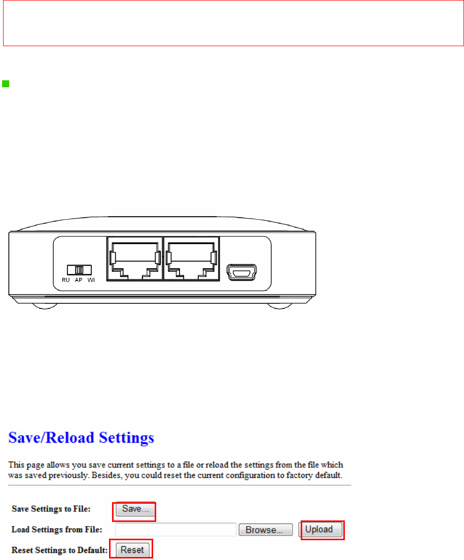
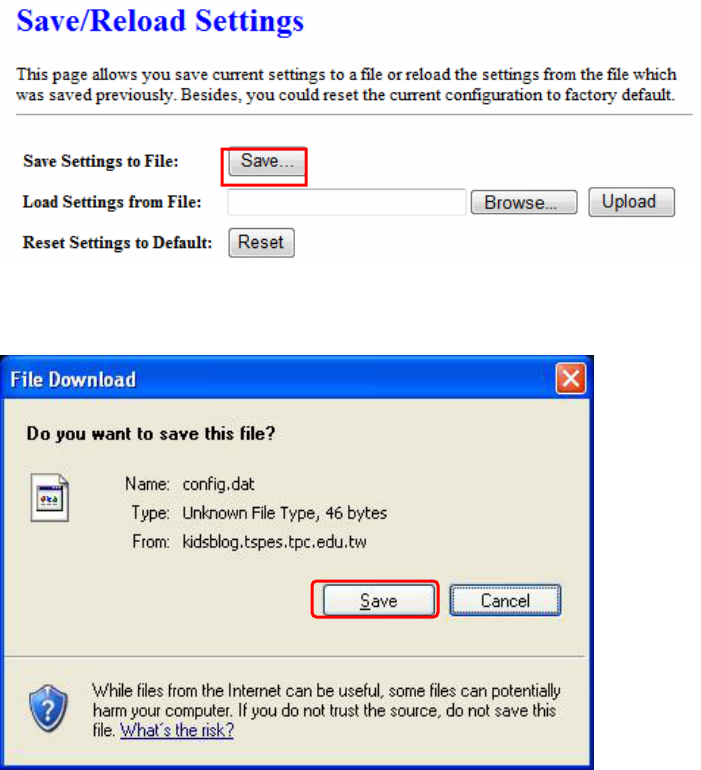
5.5.3 Save / Reload Settings
To back up the current configuration setting or load the backup data, also you can restore 11N
Mini Broadband Router to default setting by this function.
Version 1.0.15
80
1. Save Settings To File
Step 1. Click on Save button for saving the configuration setting into assigned
location.
A pop window will show up and ask to save config.dat file.
Step 2. Please select the location, for example: the desktop.
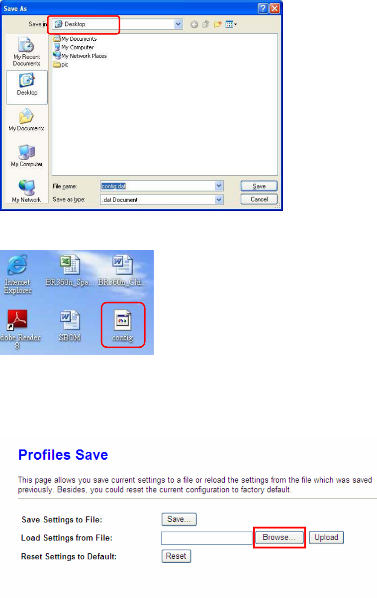
Version 1.0.15
81
Step 3. The file you just saved will appear on the desktop.
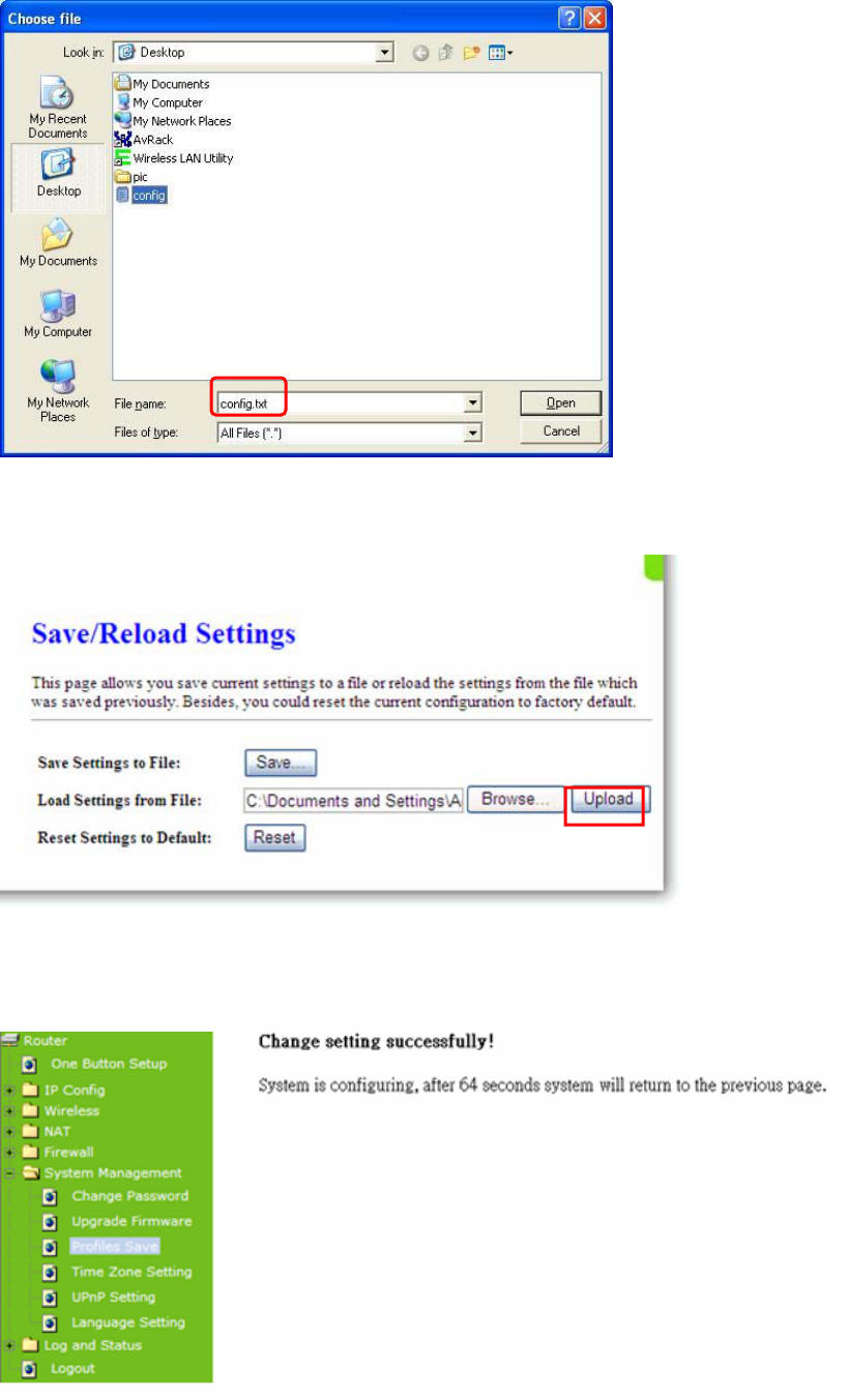
2. Load Settings From File
Step 1. Click on “Browse…” button for searching the saving configuration from hard
drive, and then click on Upload button to load all the settings into the router.
Step 2. Select the config.dat file.
Version 1.0.15
82
Step 3. Click Upload to retrieve.
Step 4. When you see the screen below, the updating is completed. Please click OK to
return to the main menu.
Version 1.0.15
83
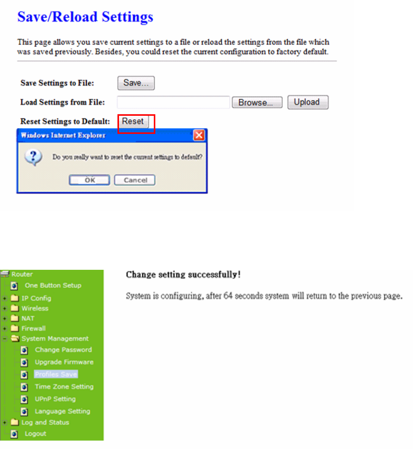
3. Reset Setting to Default
After you have tried other methods for troubleshooting your network, you may choose to
restore 11N Mini Broadband Router to the factory default settings.
When you see the screen below, the resetting is completed. Please click OK and return to the
main menu.
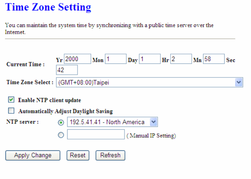
5.5.4 Time Zone Setting
The System time is the time used by 11N Mini Broadband Router for scheduling services.
You can manually set the time or connect to a NTP (Network Time Protocol) server. If a NTP
server is set, you will only need to set the time zone. If you manually set the time, you may
also set Daylight Saving dates and the system time will automatically adjust on those dates.
Version 1.0.15
84
1. Current Time
Users can input the time manually.
2. Time Zone Select
Select your time zone location from the drop-down list.
3. Enable NTP client update
Check to enable NTP client update.
4. Automatically Adjust Daylight Saving
If you are in daylight saving time area, please enable this item.
5. NTP server
Please select the NTP server from the pull-down list, or you can enter the NTP server IP
address manually.
6. Apply Changes & Reset & Refresh
Please click on Apply Changes to save the setting data. Or you may click on Reset to clear
all the input data. Or you may click on Refresh to update the system time on the screen.
7. NTP Server Type & Default NTP Server
Version 1.0.15
85
Choose “General Time Server” and select the NTP Server from the drop-down list or
choose “Customized Time Server” and enter the server by manual.
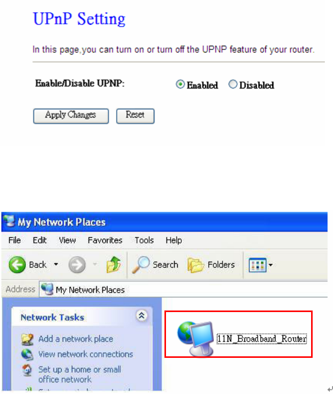
5.5.5 UPnP Setting
UPnP (Univsersal Plug and Play) allows users to connect their UPnP-enabled Mini Router,
printer server and other devices right to the network with zero-configuration, meaning easier
setup for installing the device on the network. The automatic discovery feature enables the
device to obtain an IP address, present and describe itself to other devices and PCs on the
network without having to install drivers, but to configure and use those devices.
After enabling UPNP, click My Network Places, and user can open the web GUI by just
clicking on the Internet Gateway Device icon.
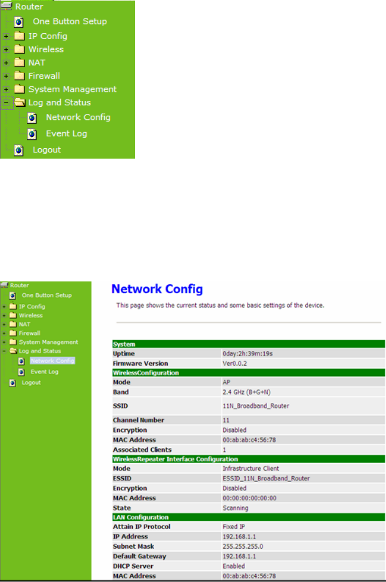
5.6 Log & Status
Version 1.0.15
86
11N Mini Broadband Router provides the log list and connection status for user to check.
5.6.1 Network Config
Network Configuration shows the firmware version and the connection status of LAN, WAN
and Wireless.
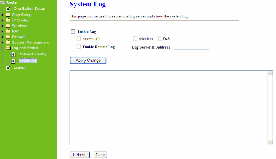
5.6.2 Event Log
Version 1.0.15
87
11N Mini Broadband Router provides system logs for review.
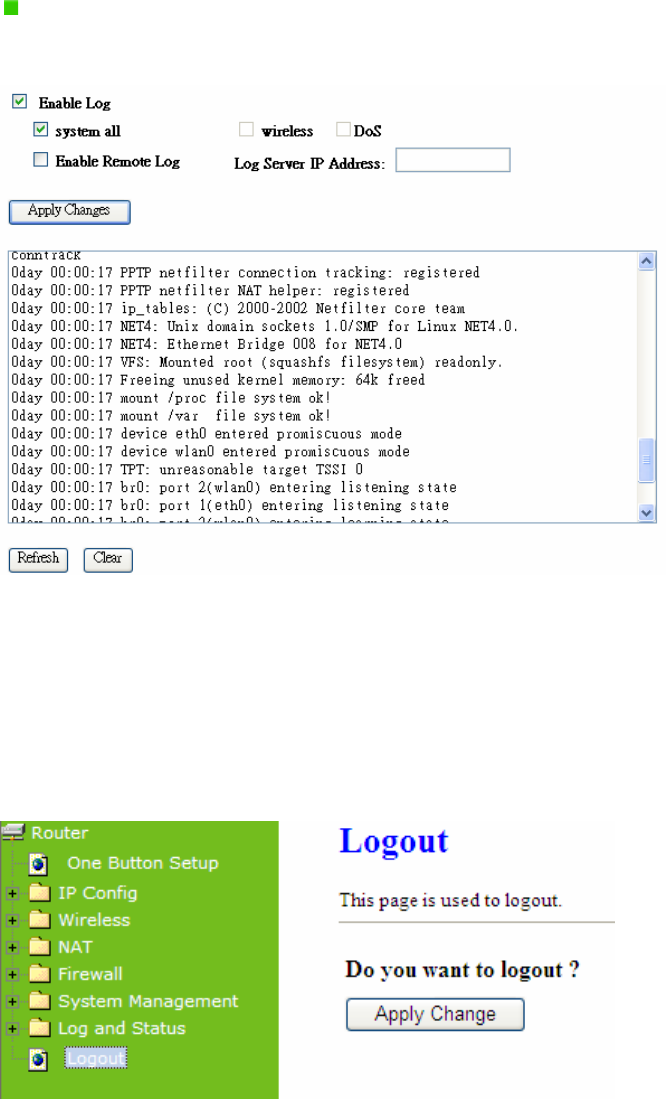
1. Enable Log
Select Enable Log to record the system log
2. system all, wireless & DoS
Select Wireless, DoS or system all to record
3. Enable Remote Log
You may choose to enable the remote event log or not.
4. Log Server IP Address
Please input the log server IP Address.
5. Apply Changes & Refresh & Clear
Click on Apply Changes to save the setting data. Click on Refresh to renew the system time,
or on Clear to clear all the record.
Version 1.0.15
88
After clicking Apply Changes to record the event log, it will be shown as the example
below.
5.7 Logout
Click Logout on the bottom menu to exit and go back to GUI login home page.
Chapter 6 Advance Configuration for AP Mode
Version 1.0.15
89
6.1 IP Configuration
This function allows you to add routing rules into 11N Mini Broadband Router , including LAN
and Site Survey.
6.1.1 LAN Setup
Use this page to set up the local IP address and subnet mask for your router. Please select
LAN under the IP Config menu and follow the instructions below to enter the LAN setting
page to configure the settings you want.
6.1.2 LAN Interface Setup
Version 1.0.15
90
1. IP Address
The default value of LAN IP address is 192.168.1.254 for this router.
2. Subnet Mask
Input Subnet Mask, normally it is 255.255.255.0.
3. Default Gateway
Input ISP Default Gateway Address. If you don’t know, please check with your ISP.
4. DHCP
Enable or disable DHCP services. The DHCP server will automatically allocate an unused IP
address from the IP address pool to the requesting computer if enabled.
5. DHCP Client Range
Define the DHCP client range and then the DHCP server will assign an IP to the requesting
computer from this range. The Show Client will display every assigned IP address, MAC
address, and expired time. The default range is 192.168.1.100 - 192.168.1.200.
6. 802.1d Spanning Tree
IEEE 802.1d Spanning Tree Protocol (STP) is a link layer network protocol that ensures a
loop-free topology for any bridged LAN. The main purpose of STP is to ensure that you do not
create loops when you have redundant paths in your network. Loops are deadly to a network.
7. Clone MAC Address
Copy the MAC address from the device you had registered to your ISP if your ISP asks for
the specific MAC Address.
8. Apply Changes & Reset
Click on Apply Changes to save the setting data. Or you may click on Reset to clear all the
input data.
6.2 Wireless Setup
Please select Wireless under the main menu.
Version 1.0.15
91
6.2.1 Wireless Basic Settings
Follow the instructions to configure the Wireless settings.
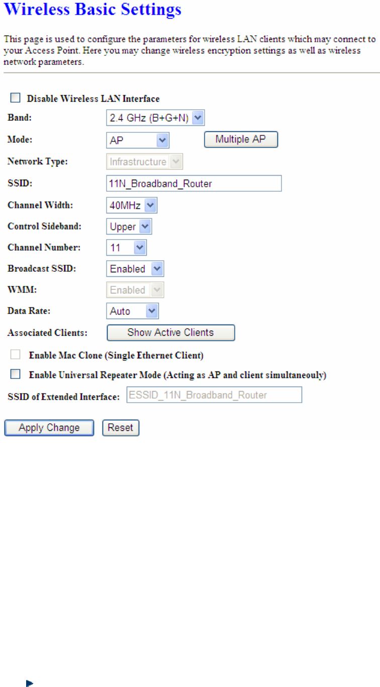
Version 1.0.15
92
1. Disable Wireless LAN Interface
Select Disable Wireless LAN Interface to turn off the wireless function.
2. Band
This field indicates the 802.11x interface mode. For example, “2.4GHz(G)” prevents the
802.11b clients from accessing the router. “2.4GHz(B+G)” allows both 802.11b and 802.11g
clients to access the router. There are 6 options, 2.4 GHz (B/G/N/B+G/G+N/B+G+N) from the
drop down list.
3. Mode
Select AP, WDS, or AP+WDS to allow or disallow the wireless operation.
Multiple APs
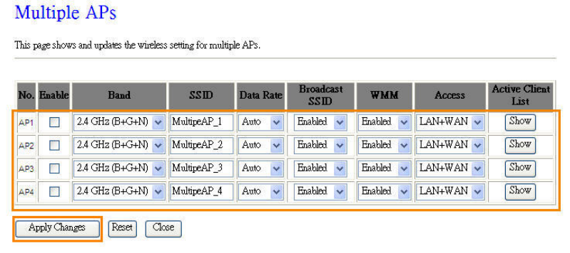
Version 1.0.15
93
Click Multiple APs to set up 4 different SSIDs to deploy a shared WLAN. Users can add
or limit the properties for each SSID, increasing the flexibility and efficiency of the
network.
(1.) Enable: check it for enable or not.
(2.) Band: select the frequency from the drop down list.
(3.) SSID: please enter different SSID in each class.
(4.) Data Rate: please select the data transmission rate.
(5.) Access: defined the access type.
a. LAN+WAN: the client can access to the Internet and connect to 11N Mobile
Router’s GUI to setup.
b. WAN: the client can only access to the Internet.
(6.) Active Client List: display the properties of the client which is connecting
successfully.
(7.) Apply Changes: Please click Apply Changes to initiate or click Reset to cancel.
4. Network Type:
Please select “Infrastructure” or “Ad hoc.” The default is “Infrastructure.” The selection is
disabled when wireless mode is selected to AP.
5. SSID:
Please input your wireless network name. Default is “11N_Mini_Router”.
6. Channel Width
Please select “20MHZ” or “40MHZ” channel width to change the transmission channels.

Version 1.0.15
94
7. ControlSideband
Setting the Sideband "Upper" or "Lower.”
8. Channel Number
Please select your wireless network channel. There are Auto, 2~11.
9. Broadcast SSID
Enable or disable the SSID broadcast function. Disable this feature can provide more security
of your WLAN.
10. Data Rate
Rate at which data can be communicated (bps); auto, 1M, 2M, 5.5M, 11M, 6M, 9M, 12M, 18M,
24M, 36M, 48M or 54M to be selected from the drop-down list.
11. Associated Clients
Check the WiFi ISP connectors and the connecting status.
12. Enable Mac Clone (Single Ethernet Client)
Copy the MAC Address for identity of some ISPs.
13. Enable Universal Repeater Mode (Acting as AP and Client simultaneously)
Enable Universal Repeater Mode, 11N Mini Broadband Router will act as a wireless AP
and AP client at the same time, and able to link to another AP.. It uses AP client function to
connect to a Root AP (any AP) and uses AP function to service all wireless stations within its
coverage. All the stations within the coverage of 11N Mini Broadband Router can be bridged
to the Root AP. It can help user to extend the coverage of wireless network.
How to Enable URM (Universal Repeater Mode)
User could enable URM in wireless basic setting page as shown in following figures.
Step 1. Get back to menu “Network Config” and write down the SSID, channel and
security.
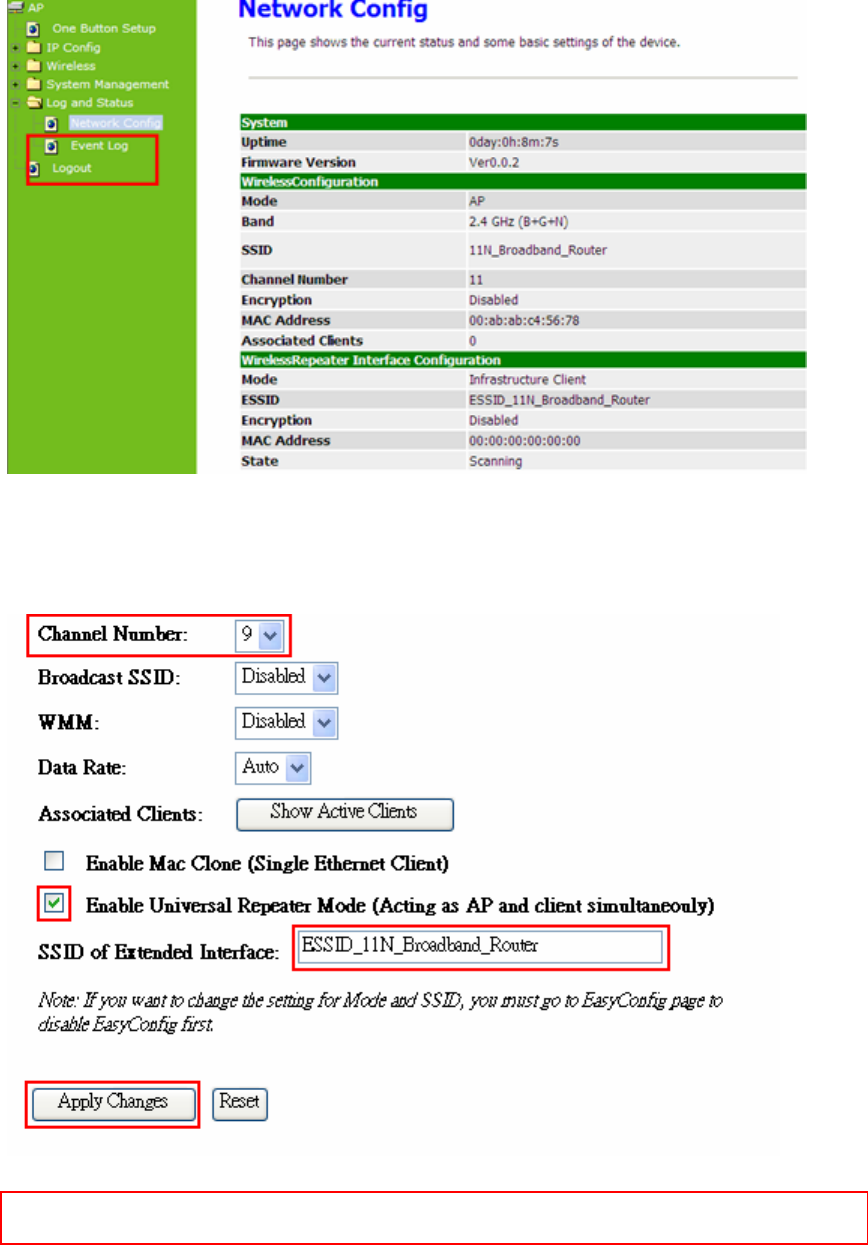
Version 1.0.15
95
Step 2. Setting the same SSID, channel and security you got form “Network Config”
and Click on Apply Changes to save the setting
Note: The DHCP server should be disabled under menu “LAN Interface Setup” and then the URM could be
enabled.
Step 3. Check the AP connectors and the Wireless connecting status.
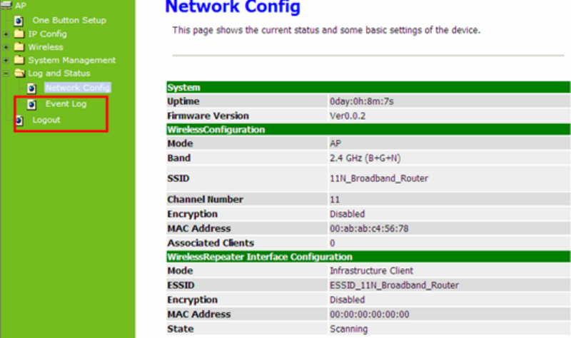
Version 1.0.15
96
14. SSID of Extended Interface
When mode is set to “AP” and Universal Repeater Mode is enabled, user should input SSID
of another AP (the upper level device) in the field of SSID of Extended Interface.
15. Apply Changes & Reset
Click on “Apply Changes” to save the setting data. Or you may click on “Reset” to clear all
the input data.
6.2.2 Wireless Advanced Settings
Please follow the instructions to configure the Wireless settings.
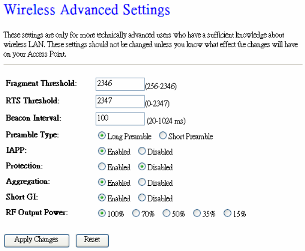
Version 1.0.15
97
1. Fragment Threshold
To identify the maximum length of packet, the overflow packet length wil be fragmentized.
The allowed range is 256-2364, and default length is 2346 bytes.
2. RTS Threshold
This value should remain at its default setting of 2347. The range is 0~2347. Should you
encounter inconsistent data flow, only minor modifications are recommended. If a network
packet is smaller than the present RTS threshold size, the RTS/CTS mechanism will not be
enabled. The router sends Request to Send (RTS) frames to a particular receiving station
and negotiates the sending of a data frame. After receiving an RTS, the wireless station
responds with a Clear to Send (CTS) frame to acknowledge the right to begin transmission.
Fill the range from 0 to 2347 into this blank.
3. Beacon Interval
Beacons are packets sent by an access point to synchronize a wireless network. Specify a
beacon interval value. The allowed setting range is 20-1024 ms.
4. Preamble Type
The preamble (also called “a header”) is a section of data at the head of a packet that
contains information that wireless devices need when they send and receive packets. Short
preambles improve throughput performance, but some wireless devices require long
preambles. Select the suitable preamble as short or long preamble.
5. IAPP
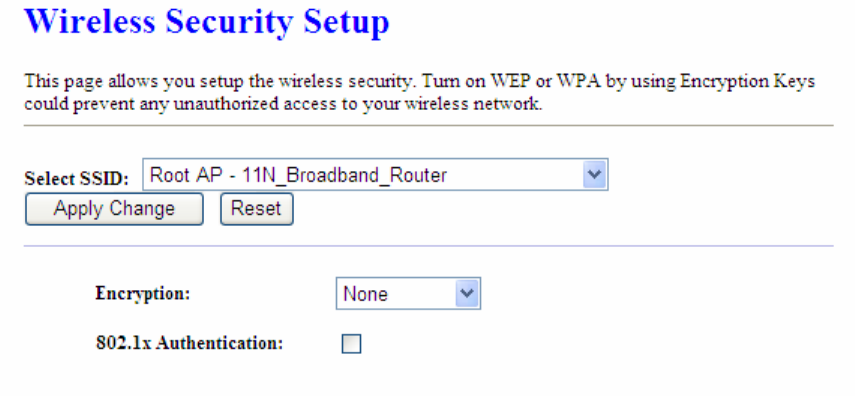
Version 1.0.15
98
Inter Access Point Protocol. Allow seamless roaming between Access Points in your
wireless network. Coupled with superior RF performance
6. Protection
Select to enable the wireless protection or not.
7. Aggregation
Data aggregation can reduce the amount of data routed through the network, and increasing
throughput.
8. Short GI
Enabling the Short Guard Interval increases the wireless transmission.
9. RF Output Power
User can adjust the RF output power to get the best wireless connection. There are 5 power
types available: 100%, 70%, 50%, 35%, and 15%.
10. Apply Changes & Reset
Click on “Apply Changes” to save the setting data. Or you may click on “Reset” to clear all the
input data.
6.2.3 Wireless Security Setup
4 encryption types can be selected here, please follow the instructions below for each.
1. Encryption – WEP
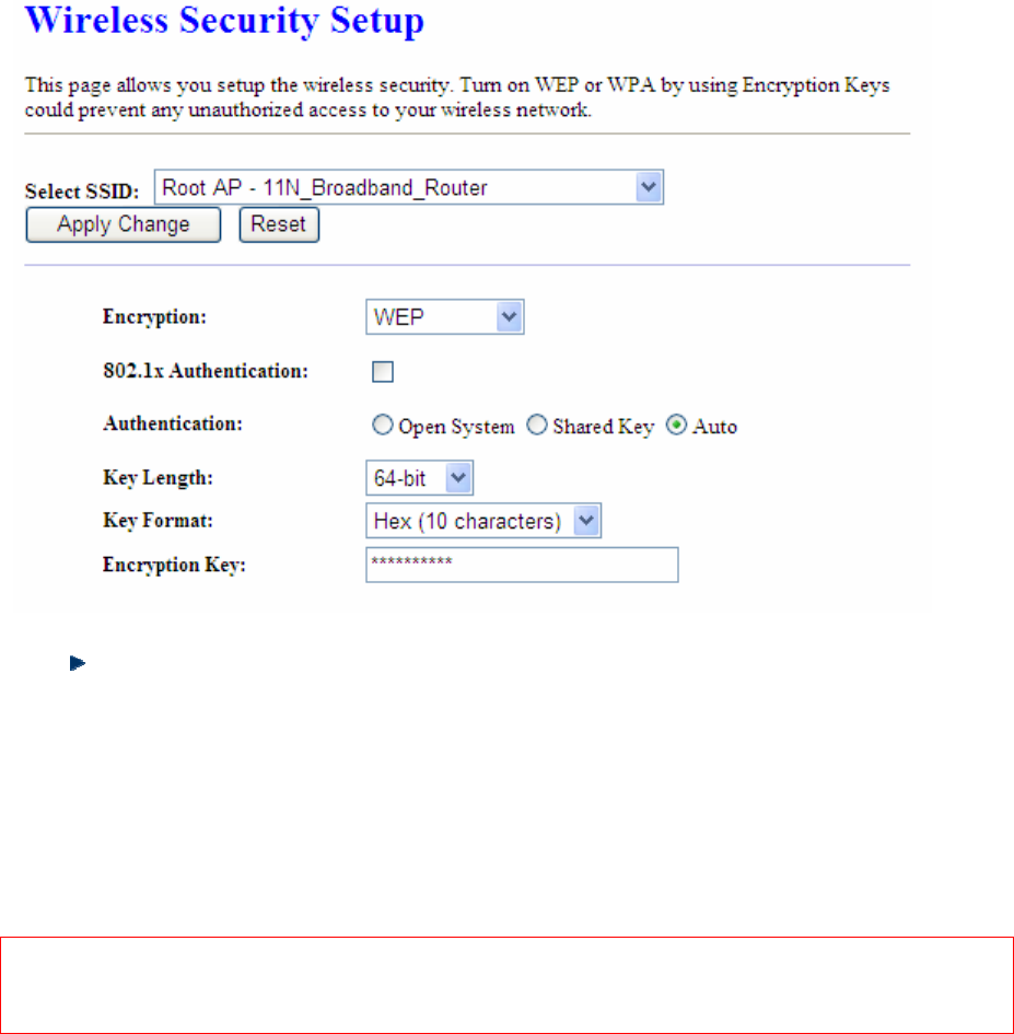
Version 1.0.15
99
Enabling WEP can protect your data from eavesdroppers. If you do not need this feature,
select “None” to skip the following setting. 11N Mini Broadband Router supports both 64-bit
and 128-bit encryption using the Wired Equivalent Privacy (WEP) algorithm. Select the type
of encryption you want to use (64 or 128 bit) and configure one to four WEP Keys. The
“1280bit” method is more secure than the “64-bit”.
Use 802.1x Authentication
Enable 802.1x Authentication so that a wireless node must be authenticated before it
can gain access to other LAN resources.
Key Length: For 64bits WEP key, either 5 ASCII characters or 10 hexadecimal digitals
leading by 0x can be entered. For 128bits WEP key, either 13 ASCII characters or 26
hexadecimal digits leading by 0x can be entered.
Note: 128 bits WEP is most secure, but has more encryption/decryption overhead. Note that all wireless devices
must support the same WEP encryption bit size and have the same key. Four keys can be entered here, but
only one key can be selected at a time. The keys can be entered in ASCII or Hexadecimal. Select the item
from drop-down list you wish to use.
Encryption Key: At most four keys can be set. A WEP key is either 10 or 26
hexadecimal digits (0~9, a~f, and A~F) based on whether you select 64 bit or 128 bit in
the WEP drop-down list.
2. Encryption – WPA (WPA, WPA2 & WPA2 Mixed)
The WPA, WPA2 & WPA2 Mixed encrypt each frame transmitted from the radio using the
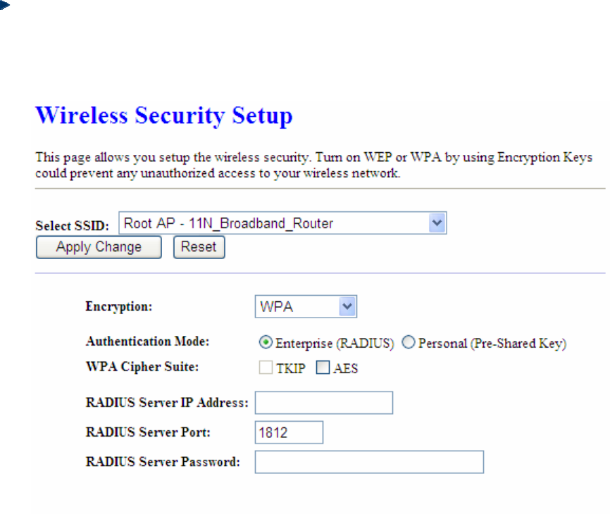
Version 1.0.15
100
pre-shared key (PSK) which entered from this panel or a key got dynamically through
802.1x.
WPA Authentication Mode
Enterprise (RADIUS): Please input the port, IP address, and password of
authentication RADIUS Server.
Personal (Pre-Shared Key): Pre-Shared Key type is coding in ASCII, and the
length is between 8 to 63 characters. If the coding is in Hex, the key length is 64
characters.