Planex Communications CS-WDP06G Network Camera User Manual
Planex Communications inc. Network Camera
UserManual.wiki
>
Planex Communications
>
CS WDP06G User Manual
User manual
Navigation menu
Upload a User Manual
Namespaces
Wiki Guide
HTML
PDF
Info
Views
User Manual
Discussion / Help
Navigation
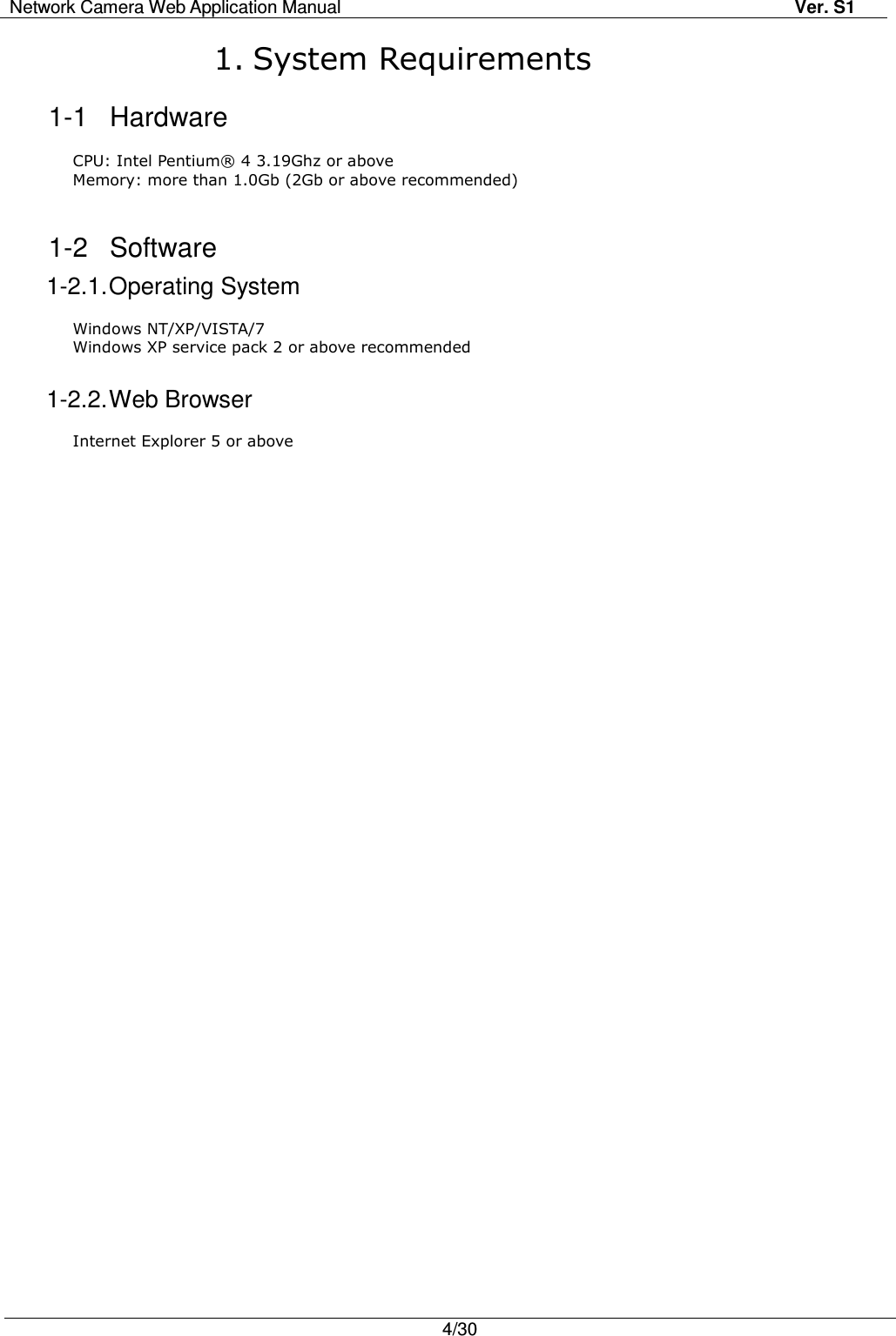
![Network Camera Web Application Manual Ver. S1 6/30 2-2 Installing ActiveX viewer Control Access the main page of the camera. Log in with your ID and password. Click OK if the dialogue box asking whether you want to install ActiveX viewer control is displayed. If the information bar above appears due to security setting, download will be initiated by clicking the information bar and selecting [File Download]. When the download window appears, click the Run button.](https://usermanual.wiki/Planex-Communications/CS-WDP06G/User-Guide-1429625-Page-6.png)
![Network Camera Web Application Manual Ver. S1 7/30 Windows 7/Internet explorer 8 (a case prior to downloading/installing setup.exe) If the information bar above appears prior to downloading or installing setup.exe, click [File Download Blocked>File Download]. When the installation is complete, click “Finish”. In order to apply the installed ActiveX configuration, renew the web page by clicking F5 key or [Reload]. If the information bar asking whether you want to execute Web viewer is displayed, click OK.](https://usermanual.wiki/Planex-Communications/CS-WDP06G/User-Guide-1429625-Page-7.png)
![Network Camera Web Application Manual Ver. S1 8/30 In case of Windows7/Internet explorer 8 (after installing setup.exe) After installation, if the information bar is shown, click it and select [Not using additional functions>Running additional functions]. After installation, if the information bar is shown, click it and select [Running additional functions].](https://usermanual.wiki/Planex-Communications/CS-WDP06G/User-Guide-1429625-Page-8.png)
![Network Camera Web Application Manual Ver. S1 9/30 2-3 Deleting ActiveX viewer Control Run [Start>Control Panel>Add/Remove Programs]. Remove it by clicking the button, S1 Network Solution – Remove Web Viewer. If it is removed, click Confirm.](https://usermanual.wiki/Planex-Communications/CS-WDP06G/User-Guide-1429625-Page-9.png)
![Network Camera Web Application Manual Ver. S1 20/30 4-5-4. Schedule setting This page is for setting Schedule. It is possible to set for sending by E-mail, or saving on network shared folder separately. Setting Method Input ID, password and select user group. After that, click the saving button. Reference Setting at the same time: Select/Cancel from 0 to 24 hrs together. Morning/Afternoon: Select/Cancel morning/afternoon at the same time. Time setting: Select/Cancel time in the unit on an hour basis. Operation setting Start/Stop: When saving, select the operation of Schedule schedule. Setting file: You can save or open the daily schedule. It is possible to set the weekday/weekend/daily schedule. Timer interval: Set time interval of sending image. Type: Format of sending image Size: Size of sending image Schedule save/Call function Save Image: Click a save button for saving schedule of selected day on [Trigger setting>Schedule Setting], and if in [Action>Start/Stop], the button is on the ‘Start’, the schedule sending is started. If the button is on the ‘Stop’, schedule is only saved and the schedule on operation is stopped. Load Image: Call the schedule of the day on Combo box [Trigger setting>Schedule Setting].](https://usermanual.wiki/Planex-Communications/CS-WDP06G/User-Guide-1429625-Page-20.png)
![Network Camera Web Application Manual Ver. S1 23/30 On the log displaying page, you can check the log of the page by clicking the number of page. If there are many logs, they are displayed by 10 pages. For going back to previous page, click the Menu button. Order of displaying Access log [DD/MM/YYYY:hh:mm:ss_Time]_IP Address_ Access ID 4-7-4. Update When update is needed, upload the package on camera and update. * Operation method (1) Click the ‘Search’ button for calling package file. (2) Click the upload button for uploading updated package on camera (3) When there is upload success message, and package is displayed on the list, click the update button. (4) When update is finished, it is loaded again. Finally reset the camera.](https://usermanual.wiki/Planex-Communications/CS-WDP06G/User-Guide-1429625-Page-23.png)
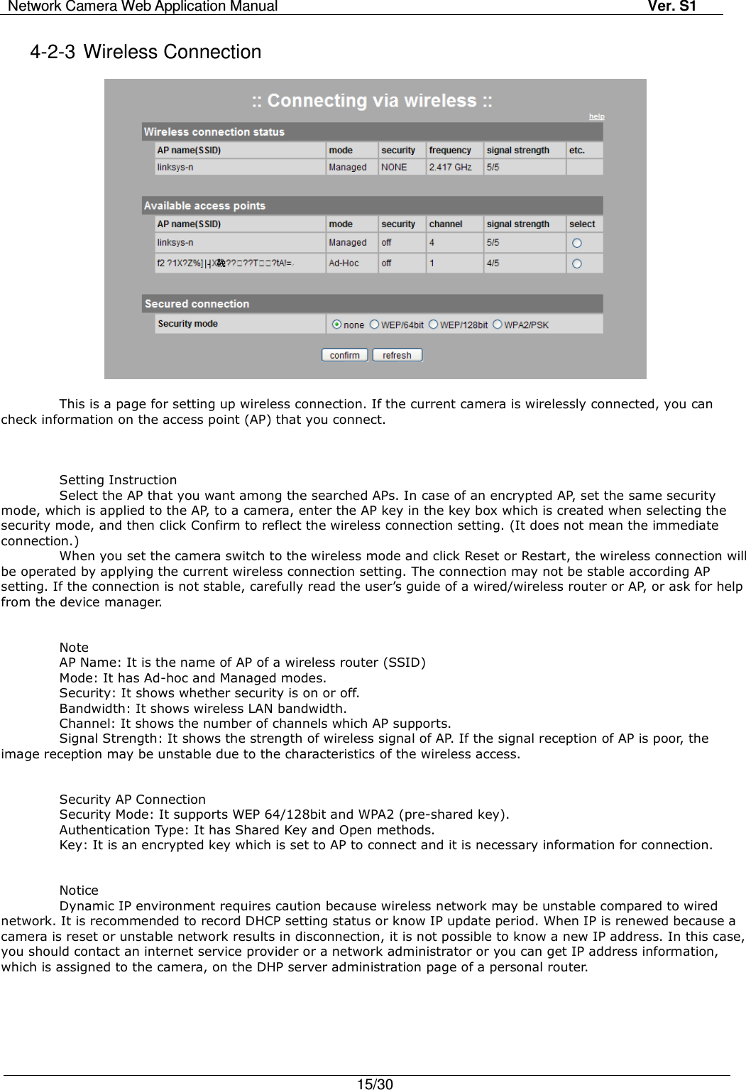
![Network Camera Web Application Manual Ver. S1 25/30 5. Example: Changing Wired Connection to Wireless Connection Preparation: Wireless AP Check whether a camera is connected in wired network before changing to wireless connection. Go to [Setup Page>Setup Network>Wireless] . Check whether there is a connectable AP around a camera and select an AP that you want as shown in the figure. AP Security Activated: Select ‘none’ in the security mode and click Confirm to save the setting. AP Security Deactivated: ‘on’ is displayed in the security mode. For AP security activated, select the security mode and enter the authentication type and key correctly. When you complete the settings, click Confirm to save the settings. Go to [Setup Page>Status>Networking] and check an IP address.](https://usermanual.wiki/Planex-Communications/CS-WDP06G/User-Guide-1429625-Page-25.png)
![Network Camera Web Application Manual Ver. S1 26/30 Connect a camera to the address set in wireless network . When the connection is successful, check the connection status at [Setup Page>Setup Network >Wireless].](https://usermanual.wiki/Planex-Communications/CS-WDP06G/User-Guide-1429625-Page-26.png)
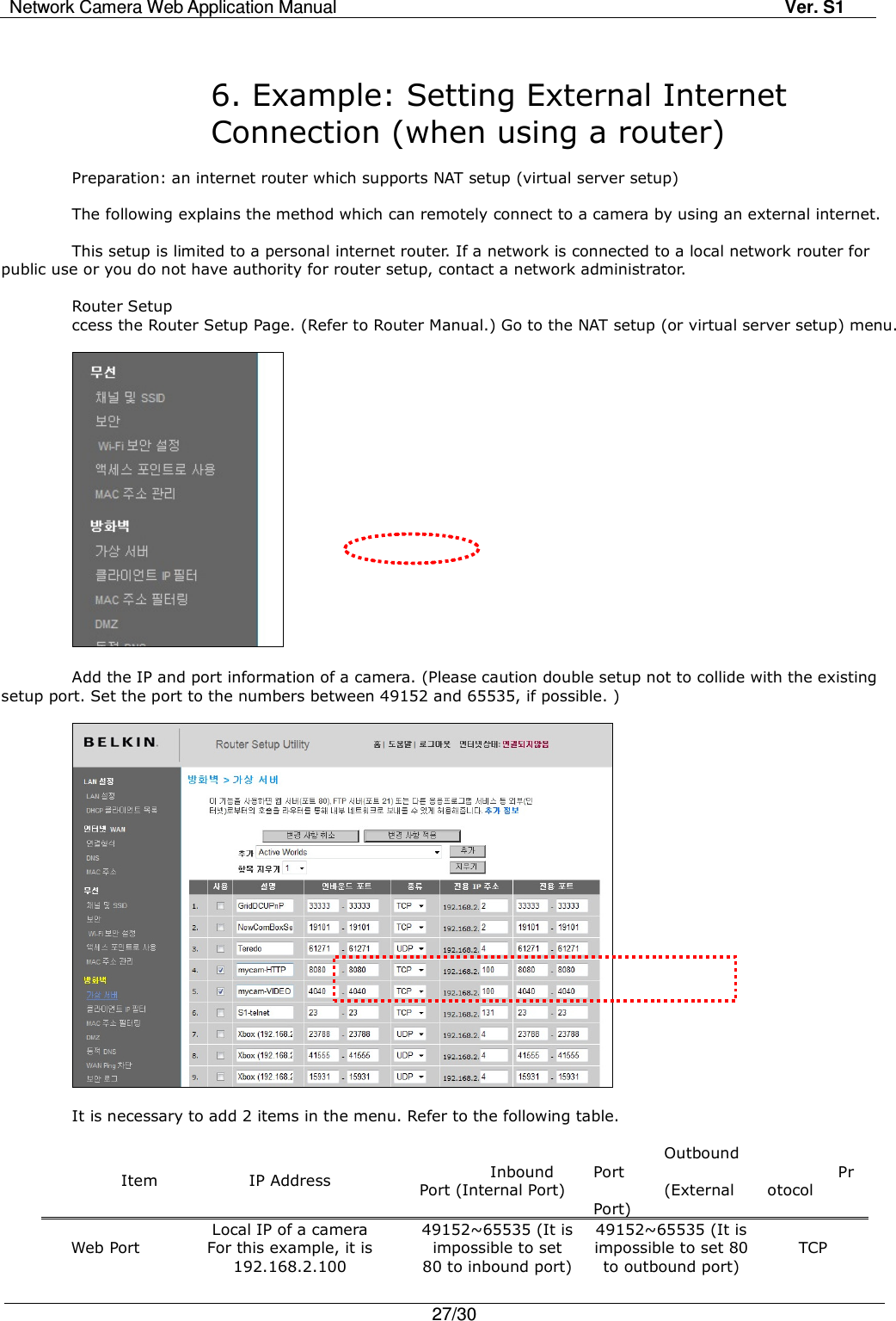
![Network Camera Web Application Manual Ver. S1 28/30 Image Port 49152~65535 49152~65535 Camera Setup Go to [Setup Page>Setup Network>IPv4>Static Setting] . Set the following necessary items by referring to the setup page of a router. HTTP/Data Port Number: Verify whether HTTP/data port number are the same with those which have been set in the router. Basic Gateway: Enter the router IP. DNS Server Address: Enter DNS server address by referring to the Setup page of the router. If there is a single DNS server address, enter the main DNS only. If there are two or more DNS server addresses, it is allowed to enter another DNS address in subsidiary DNS. When you complete the settings, save it. Access For remote connection to a web browser, URL consists of an IP which is assigned by the internet service provider of a router and HTTP port set in NAT.](https://usermanual.wiki/Planex-Communications/CS-WDP06G/User-Guide-1429625-Page-28.png)
![Network Camera Web Application Manual Ver. S1 29/30 7. Example: Using Commercial DDNS Service Preparation: A DDNS service account, an assigned domain name and a camera which can access an external internet Access a DDNS service site and check whether an assigned domain name is valid and whether an IP is properly set in the domain name. The domain name is mycam10.dyndns.org and the assigned IP is 218.209.90.51. In this case, the IP is assigned by an internet service provider. If you use a router, you should not use the local network IP of your router, but you should register the IP assigned by an internet service provider to a DDNS service site. Go to [Setup Page>Dynamic DNS Service] . In order to activate DDNS service, change the status that you can enter the form by checking the [enable/disable DDNS] box. Enter your ID and password registered in the DDNS service account. For URL, enter the domain name assigned by the DDNS service account. For DNS system, refer to the user’s guide in DDNS service site and enter the corresponding content. For update period, if an IP is static, the update period should be 24 hours. If an IP is dynamic (DHCP), the update period should be the same with or shorter than IP update period. If you save by clicking the “confirm” button, DDNS service of the camera is activated. The activation is displayed in [DDNS service status]. If the camera is turned off, DDNS service of the camera is terminated. Connect via the following url address. When using a router, the port number is HTTP port which was already set in the router. (It is set as 8080.)](https://usermanual.wiki/Planex-Communications/CS-WDP06G/User-Guide-1429625-Page-29.png)