Planex Communications CS-WDP06G Network Camera User Manual
Planex Communications inc. Network Camera
User manual

Network Camera Web Application Manual
Ver. S1
1/30
Network Camera Web Application Manual
Ver. S1
2010/12/23
ISM Development G
S/W part

Network Camera Web Application Manual
Ver. S1
2/30
Change History
Version Issue Date
Comments Approval Check Author
S1
2010-12-23
test export N/A
N/A Jung-yup Kim

Network Camera Web Application Manual
Ver. S1
3/30
Contents
1. System Requirements .................................................................................................................................. …………5
1-1.HARDWARE ............................................................................................................................................................... 5
1-2. SOFTWARE ............................................................................................................................................................... 5
1-2-1. Operating System ............................................................................................................................................ 5
1-2-2. Web Browser ................................................................................................................................................... 5
2. Initial Connection to a Camera ................................................................................................................................... 5
2-1. (S1 ) ............................................................................. 오류
오류오류
오류! 책갈피가
책갈피가책갈피가
책갈피가 정의되어
정의되어정의되어
정의되어 있지
있지있지
있지 않습니다
않습니다않습니다
않습니다.
2-2. CREATING AN ADMINISTRATOR ACCOUNT .................................................................................................................... 5
2-3. INSTALLING ACTIVEX VIEWER CONTROL ...................................................................................................................... 6
2-4. DELETING ACTIVEX VIEWER CONTROL ....................................................................................................................... 9
3. Viewer Screen ............................................................................................................................................................ 10
4. Function Setup page ................................................................................................................................................. 11
4-1. CONDITION INFORMATION ........................................................................................................................................ 13
4-1-1. Network .......................................................................................................................................................... 13
4-1-2. Session Information ....................................................................................................................................... 13
4-2. NETWORK ............................................................................................................................................................... 13
4-2-1. IPv4 ................................................................................................................................................................ 13
4-2-2. IPv6 ................................................................................................................................................................ 14
4-2-3. Wireless Connection ...................................................................................................................................... 17
4-3. DATE AND TIME ....................................................................................................................................................... 19
4-3-1. Overview ........................................................................................................................................................ 19
4-3-2. Synchronizing Time with NTP Server ............................................................................................................ 19
4-3-3. Setting Time Manually ................................................................................................................................... 19
4-4. USER ACCOUNT ...................................................................................................................................................... 20
4-4-1. Overview ........................................................................................................................................................ 20
4-4-2. Making an Account ........................................................................................................................................ 17
4-4-3. Deleting an Account ....................................................................................................................................... 17
4-5. IMAGE SENDING/SCHEDULING .................................................................................................................................. 18
4-5-1. Overview ........................................................................................................................................................ 22
4-5-2. Setting Network Folder for Sending ............................................................................................................... 18
4-5-3. Setting for E-mail ........................................................................................................................................... 19
4-5-4. Schedule setting ............................................................................................................................................ 20
4-6. DYNAMIC DNS SERVICE SETTING (DDNS) ............................................................................................................. 21
4-6-1. Overview ........................................................................................................................................................ 25
4-6-2. Activating DDNS Service ............................................................................................................................... 21
4-7. CAMERA MAINTENANCE ........................................................................................................................................... 22
4-7-1. Overview ........................................................................................................................................................ 27
4-7-2. Version Informationi ....................................................................................................................................... 27
4-7-3. Access Log .................................................................................................................................................... 27
4-7-4. Update ........................................................................................................................................................... 28
4-7-5. FPS Setup ..................................................................................................................................................... 24
5. Example: Changing Wirred Connection to Wireless Connection ......................................................................... 25
6. Example: Setting External Internet Connection (When using a router) ............................................................... 27
7. Example: Using Commercial DDNS Service ........................................................................................................... 29

Network Camera Web Application Manual
Ver. S1
4/30
1. System Requirements
1-1 Hardware
CPU: Intel Pentium® 4 3.19Ghz or above
Memory: more than 1.0Gb (2Gb or above recommended)
1-2 Software
1-2.1. Operating System
Windows NT/XP/VISTA/7
Windows XP service pack 2 or above recommended
1-2.2. Web Browser
Internet Explorer 5 or above
Network Camera Web Application Manual
Ver. S1
5/30
2. Initial Connection to a Camera
2-1 Creating an Administrator Account
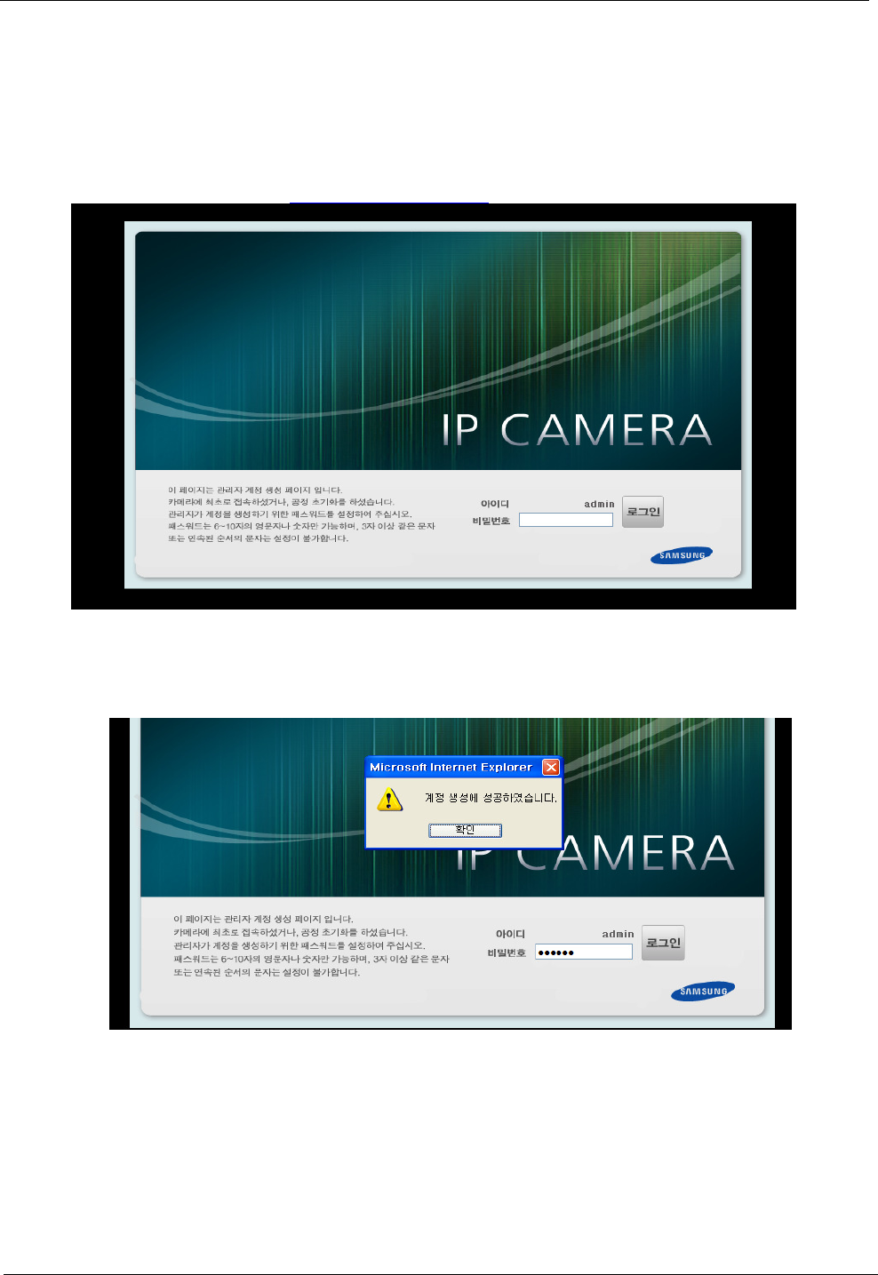
When you connect a camera after conducting the initial connection or restoring the factory default settings,
you can access the Administer Account Creation Page. The factory default IP is 192.168.0.70 and HTTP port is 8001.
The initial connection URL is http://192.168.0.70:8001.
Create your password according to the password creation rule and click the Login button to create an
account. When you create the account successfully, you will be automatically accessed to the main page of the
camera.
Network Camera Web Application Manual
Ver. S1
6/30
2-2 Installing ActiveX viewer Control
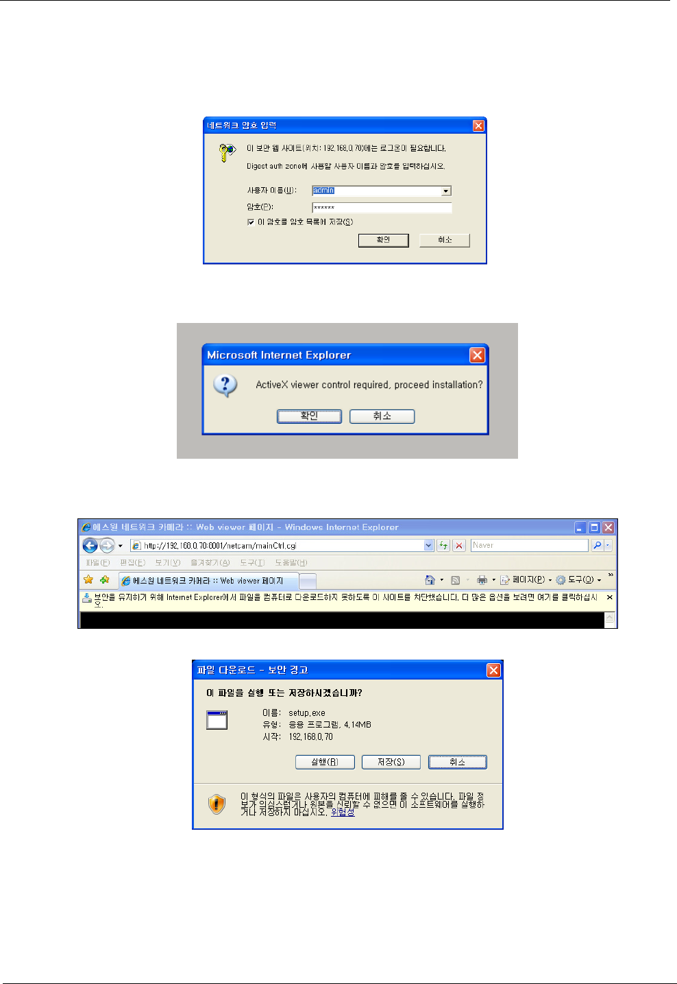
Access the main page of the camera.
Log in with your ID and password.
Click OK if the dialogue box asking whether you want to install ActiveX viewer control is displayed.
If the information bar above appears due to security setting, download will be initiated by clicking the
information bar and selecting [File Download]. When the download window appears, click the Run button.
Network Camera Web Application Manual
Ver. S1
7/30
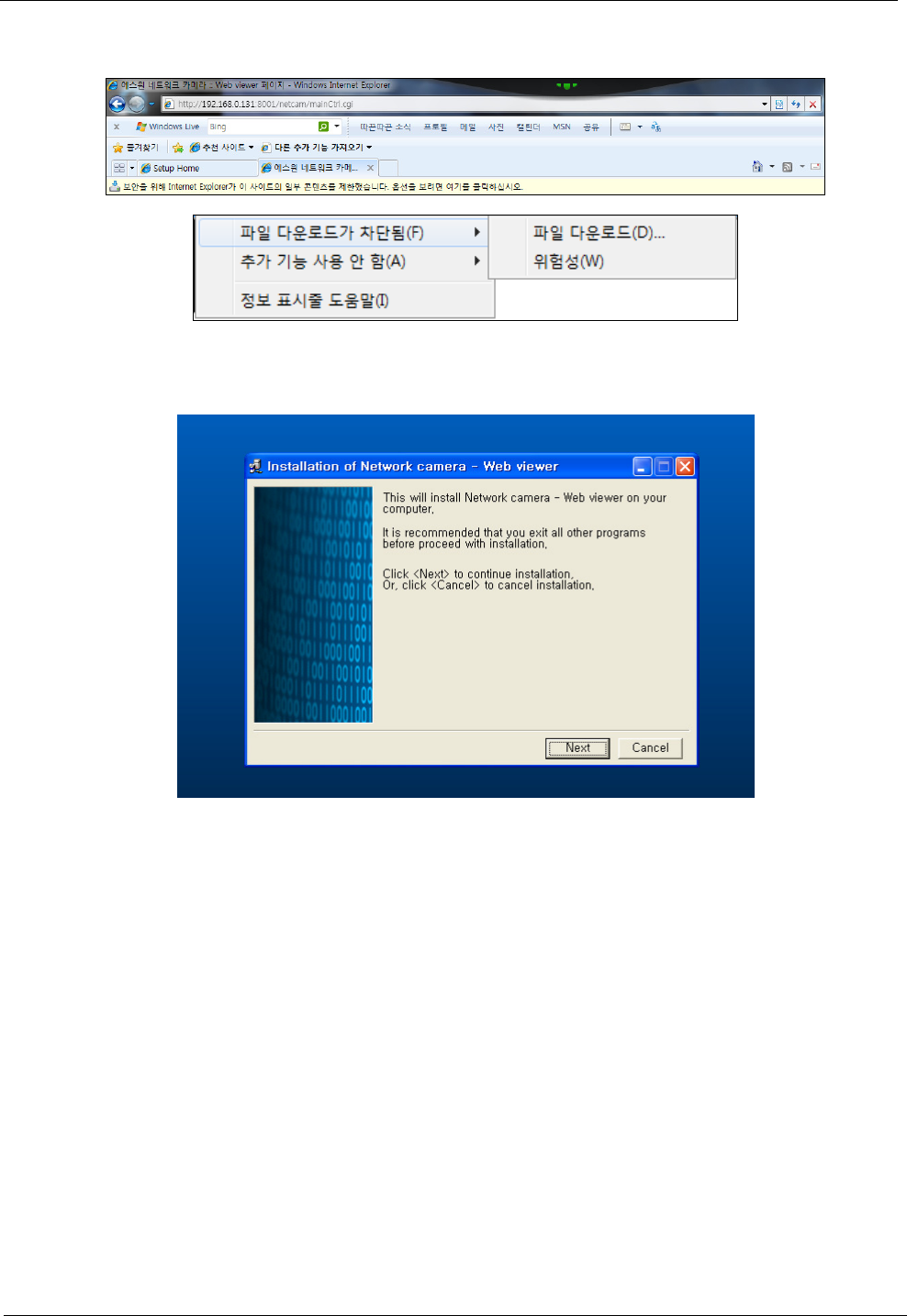
Windows 7/Internet explorer 8 (a case prior to downloading/installing setup.exe)
If the information bar above appears prior to downloading or installing setup.exe, click [File Download
Blocked>File Download].
When the installation is complete, click “Finish”.
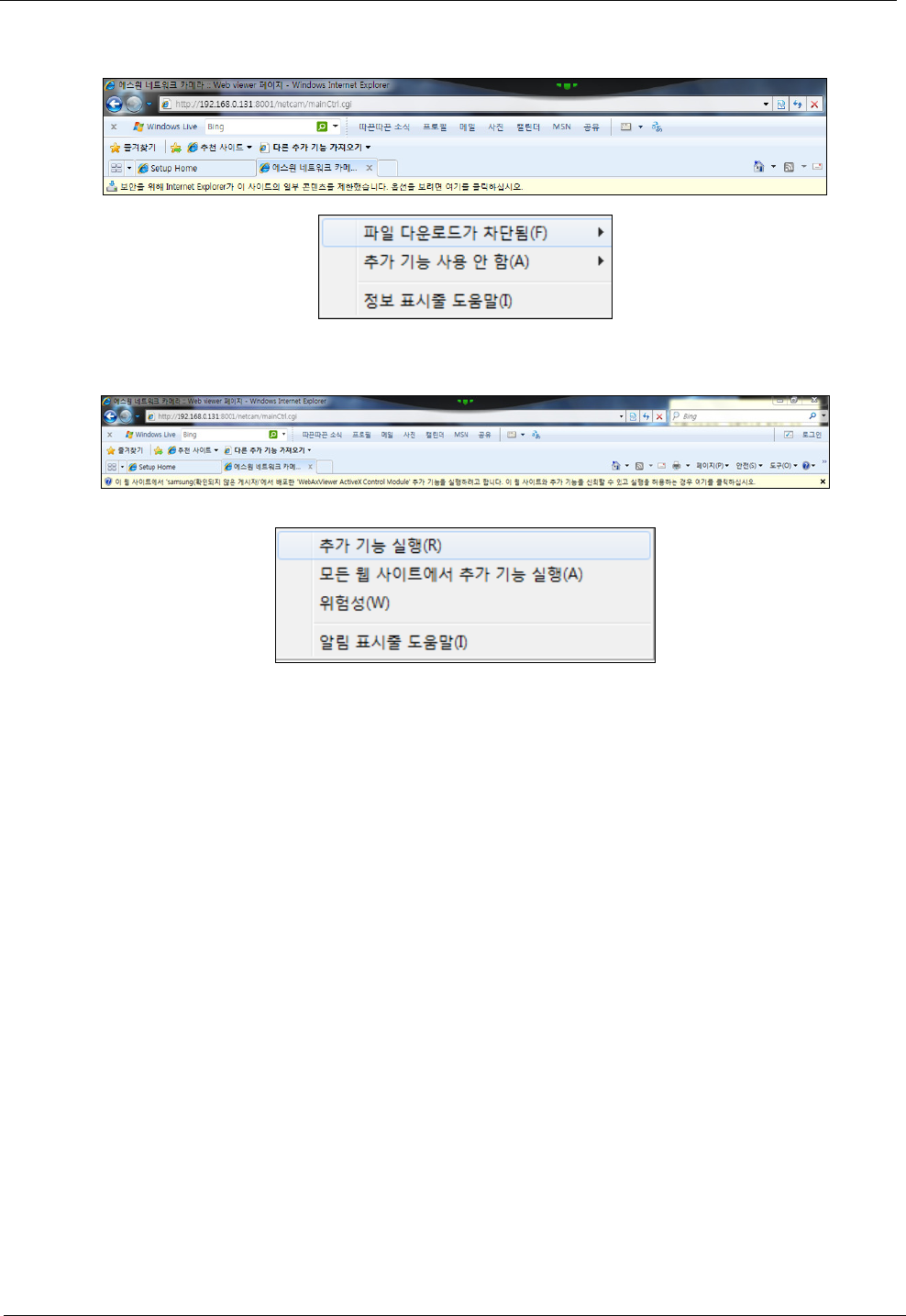
In order to apply the installed ActiveX configuration, renew the web page by clicking F5 key or [Reload]. If
the information bar asking whether you want to execute Web viewer is displayed, click OK.
Network Camera Web Application Manual
Ver. S1
8/30
In case of Windows7/Internet explorer 8 (after installing setup.exe)
After installation, if the information bar is shown, click it and select [Not using additional
functions>Running additional functions].
After installation, if the information bar is shown, click it and select [Running additional functions].
Network Camera Web Application Manual
Ver. S1
9/30
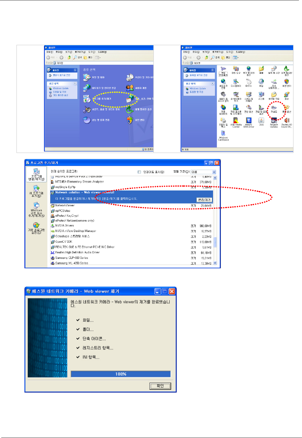
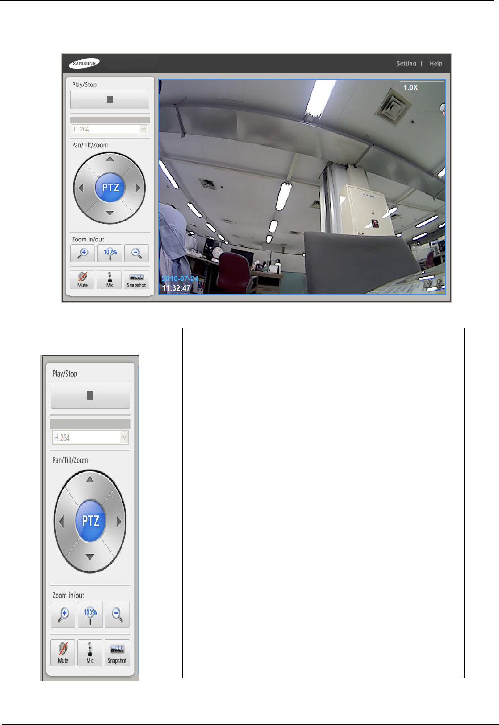
2-3 Deleting ActiveX viewer Control
Run [Start>Control Panel>Add/Remove Programs].
Remove it by clicking the button, S1 Network Solution – Remove Web Viewer.
If it is removed, click Confirm.
Network Camera Web Application Manual
Ver. S1
10/30
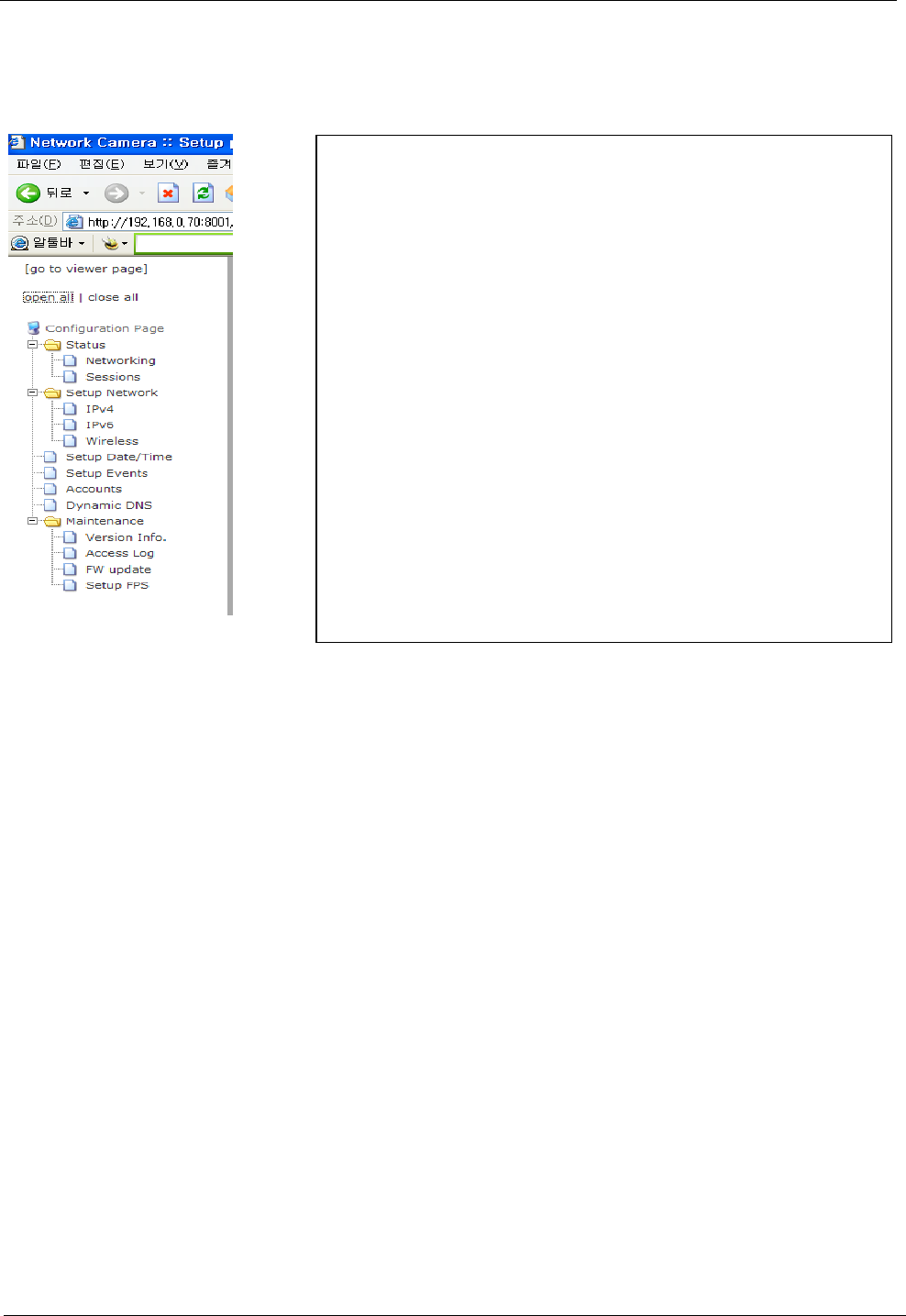
3. Viewer Screen
It is the main Viewer page. You can check and manipulate the images of the camera.
Explanation of Menu
▪Start/Stop
Play or stop the video.
▪Stream Type
You can change the stream types of the video.
MJPEG: It shows the images in relatively more detail
but the size of the video is big.
H.264: It shows the images in relatively less detail
but the size is small.
▪Pan / Tilt / Zoom
Pan
PanPan
Pan / Tilt: Move the screen to the
up/down/left/right while the zoom function is running.
Zoom: Zoom in or out by using enlargement or
reduction button. Initialize the screen by using 100% button.
▪Mute/ Mike / Snapshot
Mute: It turns ON/OFF mute mode. It is on mute
mode by default. If you press this button, you can hear the
sound of the place where the camera is installed.
Mike: While the button is pressed, the sound is sent
to the camera and the camera automatically turns into mute
mode. (a mike is needed) If you don’t press this button, the
sound is not sent and the camera turns into the previous
mode.
Snapshot: It saves stopped images as files. It is
saved as JPG files, and the route is \Samsung-SNAPSHOTS in
‘My Documents’.
▪Help
If you click it, the pages of help are opened.
Network Camera Web Application Manual
Ver. S1
11/30
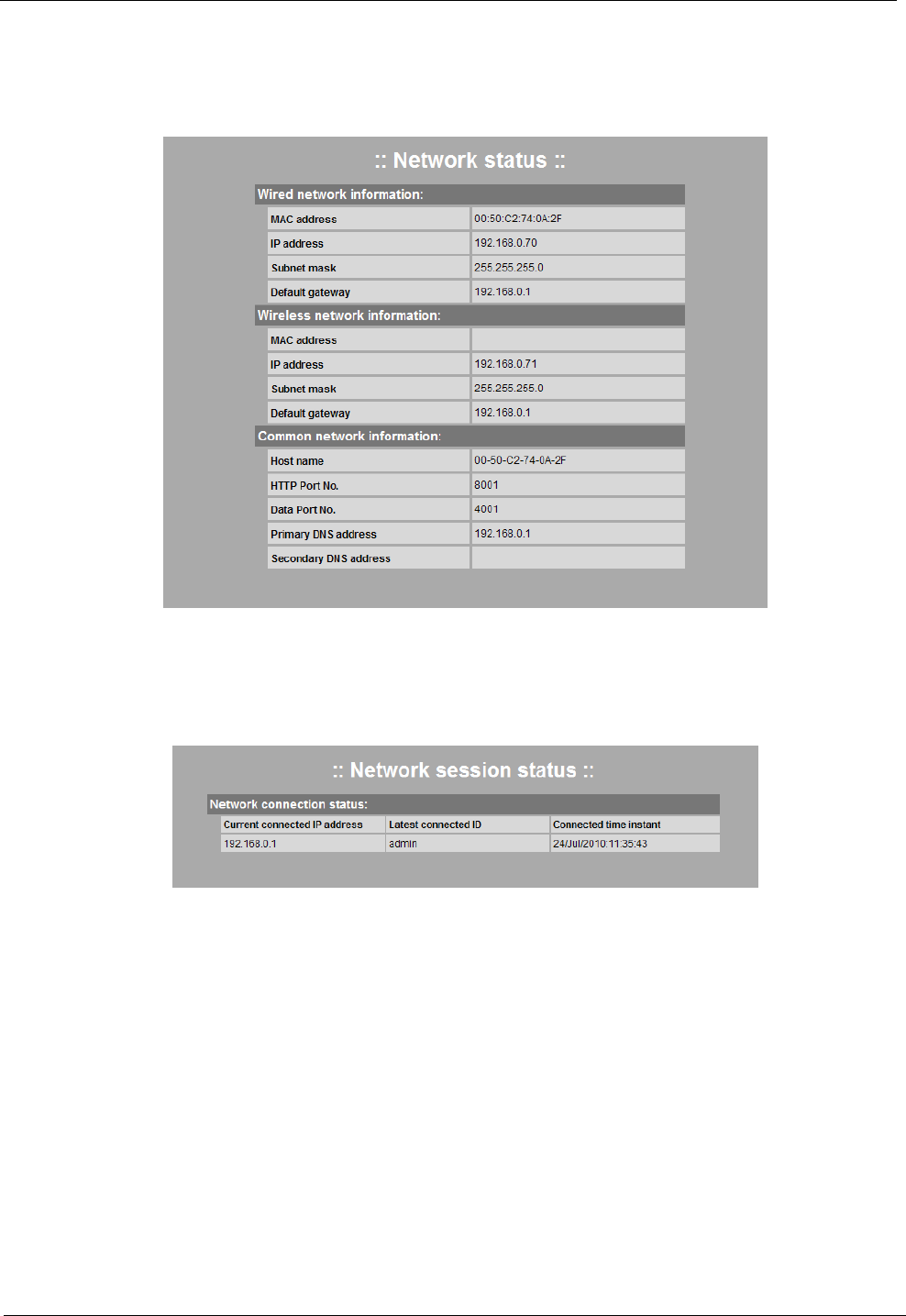
4. Function Setup page
When you select a function to set up in the tree menu on the left frame, the corresponding menu will appear
on the right frame. You can check or set the network status of the current camera.
▪Go to Viewer Page
After the setup is complete, go to the web viewer page.
▪Open All / Close All
It is to display all sub-menus of the setup tree menu or the
upper menu in the setup tree menu..
▪Setup Tree Menu
Folder Icon: When clicking it, you can see a sub-menu of the
corresponding category.
Document Icon: When clicking it, you can go to the
corresponding setup page.
Network Camera Web Application Manual
Ver. S1
12/30
4-1 Condition Information
4-1-1. Network
This page shows condition information of present network. You can check condition of setting wire/wireless
network equipment of camera.
4-1-2. Session Information
This page shows session information of present network. It shows IP of external client connected to camera,
ID, connection time.
Network Camera Web Application Manual
Ver. S1
13/30
4-2 Network
4-2-1 IPv4
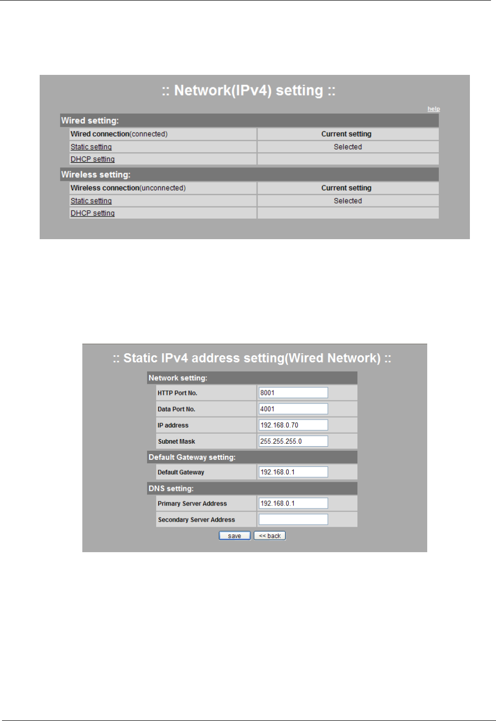
This is a page for setting up a general network based on IPv4. You can individually set up general wired and
wireless networks.
4-2-1-1 Setting LAN (wired) Network
Static IP Environment: It is when using the IP allocated by local network or an internet service provider.
You can set it up by clicking the static IP address setting.
Setting Instruction
Enter and save the network information allocated by an internet service provider. (In case of local network,
enter the router information. Please contact network administrator.) If you change the setting, the existing
connection is invalid and automatically reconnected. *HTTP port number is the port which is used for web
browser to communicate with the pages of the camera and the default is 8001. * Data port number is the
port which stream video/sound data between the viewer and the camera. The default is 4001. Please be
careful not to select duplicated port and IP.
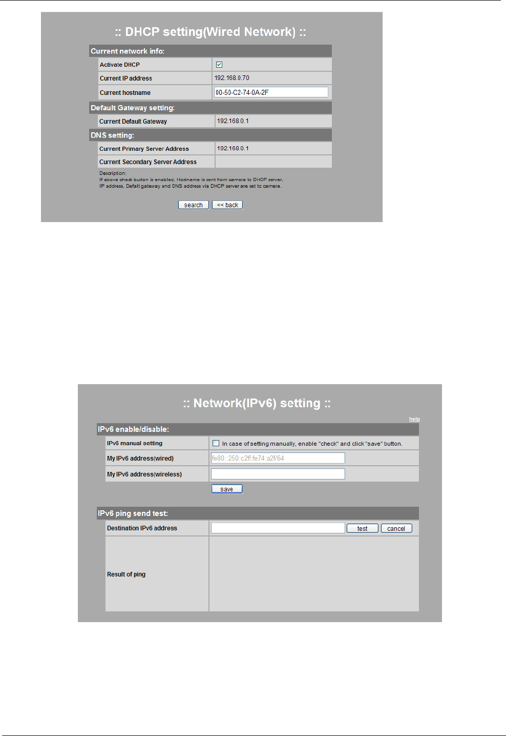
Dynamic IP Environment: If the IP allocated by local network or an internet service provider is dynamic IP
or the IP is automatically allocated by the router, you can set it up by clicking the DHCP setting.
Network Camera Web Application Manual
Ver. S1
14/30
Setting Instruction
Check the box next to Activate DHC to activate dynamic IP and click Search to search for IP. If the search is
successful, IP address, default gateway and DNS server address will be automatically assigned. Press the Save button
to save the settings. In this case, the existing connection will become invalid and it will be automatically reconnected
with the new settings. (The service may be limited based on the hardware address in some dynamic IP service areas.)
4-2-1-2 Wireless LAN(Wireless) Network Setting
It can be set up in the same way as the wired network.
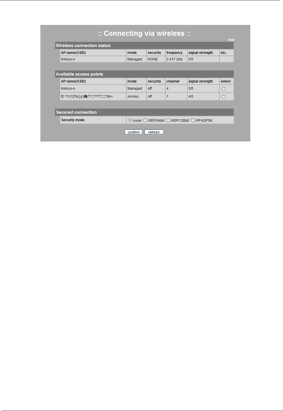
4-2-2 IPv6
This is a page for testing the IPv6-based network. This page can confirm IPv6address which is set in the
current camera network, and it can also test the IPv6 Ping.
<Reference>
IPv6 is limited to operation system of present camera. You can’t see image through IPv6.
Network Camera Web Application Manual
Ver. S1
15/30
4-2-3 Wireless Connection
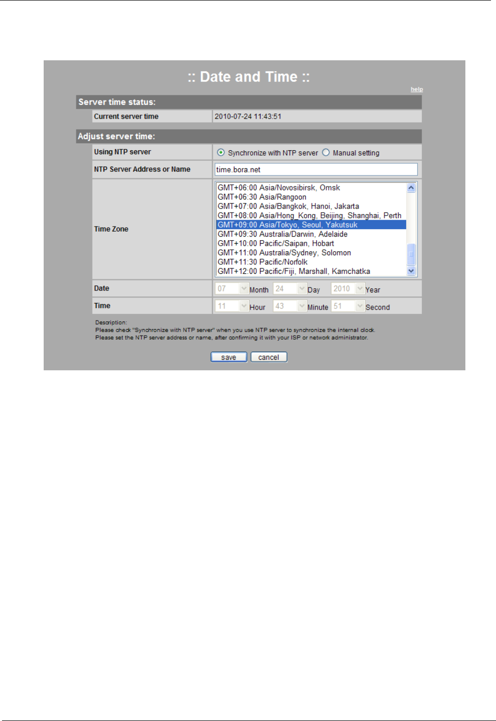
This is a page for setting up wireless connection. If the current camera is wirelessly connected, you can
check information on the access point (AP) that you connect.
Setting Instruction
Select the AP that you want among the searched APs. In case of an encrypted AP, set the same security
mode, which is applied to the AP, to a camera, enter the AP key in the key box which is created when selecting the
security mode, and then click Confirm to reflect the wireless connection setting. (It does not mean the immediate
connection.)
When you set the camera switch to the wireless mode and click Reset or Restart, the wireless connection will
be operated by applying the current wireless connection setting. The connection may not be stable according AP
setting. If the connection is not stable, carefully read the user’s guide of a wired/wireless router or AP, or ask for help
from the device manager.
Note
AP Name: It is the name of AP of a wireless router (SSID)
Mode: It has Ad-hoc and Managed modes.
Security: It shows whether security is on or off.
Bandwidth: It shows wireless LAN bandwidth.
Channel: It shows the number of channels which AP supports.
Signal Strength: It shows the strength of wireless signal of AP. If the signal reception of AP is poor, the
image reception may be unstable due to the characteristics of the wireless access.
Security AP Connection
Security Mode: It supports WEP 64/128bit and WPA2 (pre-shared key).
Authentication Type: It has Shared Key and Open methods.
Key: It is an encrypted key which is set to AP to connect and it is necessary information for connection.
Notice
Dynamic IP environment requires caution because wireless network may be unstable compared to wired
network. It is recommended to record DHCP setting status or know IP update period. When IP is renewed because a
camera is reset or unstable network results in disconnection, it is not possible to know a new IP address. In this case,
you should contact an internet service provider or a network administrator or you can get IP address information,
which is assigned to the camera, on the DHP server administration page of a personal router.
Network Camera Web Application Manual
Ver. S1
16/30
4-3 Date and Time
4-3-1 Overview
This is a page for setting the date and time of the camera.
4-3-2 Synchronizing Time with NTP Server
Setting Instruction
Select “Synchronize with NTP server,” and enter the NTP server address.
Select the time zone for your area. And click the Save button to apply the changes.
Check if the time on the server is correct.
4-3-3 Setting Time Manually
Setting Instruction
Select “Manual Setting” and set the date and time directly on the bottom of the menu.
Click the Save button to apply the changes, and check if the time on the server is correct.
Network Camera Web Application Manual
Ver. S1
17/30
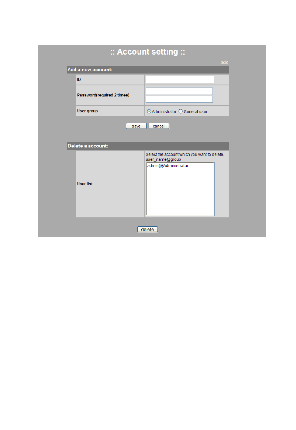
4-4 User Account
4-4-1 Overview
This is a page for managing the user account.
4-4-2 Making an Account
Setting Instruction
Enter your ID and password, designate the user group, and then click the Save button.
Note
ID: It must be 6 to 10 characters including English alphabets or numerical digits only.
Password: It must be 6 to 10 characters including English alphabets or numerical digits only. The password
cannot contain three or more consecutive digits or English alphabets in ascending or descending order and it also
cannot contain three or more same characters.
EX) hong321, zyx8010, kimzzz, luck777
User Group
Administrator: It is the user that has the authority to access and set up all of the pages.
General User: It is the user that has the authority to access the viewer page.
4-4-3 Deleting an Account
Setting Instruction
Select an account to delete by clicking the account displayed in the user list in the Account Deletion menu.
When you click the Delete button, it will be deleted and disappeared from the list.
Network Camera Web Application Manual
Ver. S1
18/30
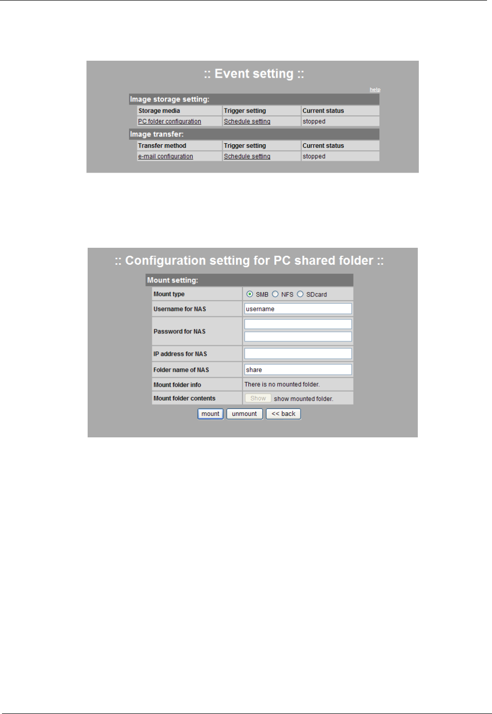
4-5 Image sending / Scheduling
4-5-1. Overview
This page is for setting event and scheduling function. It is possible to set schedule separately according to
image sending media. Image is sent by JPC file of VGA (640x480) size.
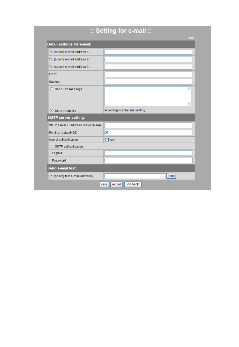
4-5-2. Setting Network Folder for Sending
This page is for setting of saving image through network sharing folder.
Setting Method
Mount/Unmount network shared folder saving image to this menu.
Mount setting
Mount file system: SMB(window), NFS(Linux)
Network shared folder user name: Input the user name of network sharing folder.
Network shared folder password: Input password of network shared folder twice, and the password should
be same.
Network shared folder IP address: Input IP address of network sharing folder.
Network shared folder name: Input folder name of network shared folder.
Mount folder information: If there is present mounted network folder, it is displayed.
Network Camera Web Application Manual
Ver. S1
19/30
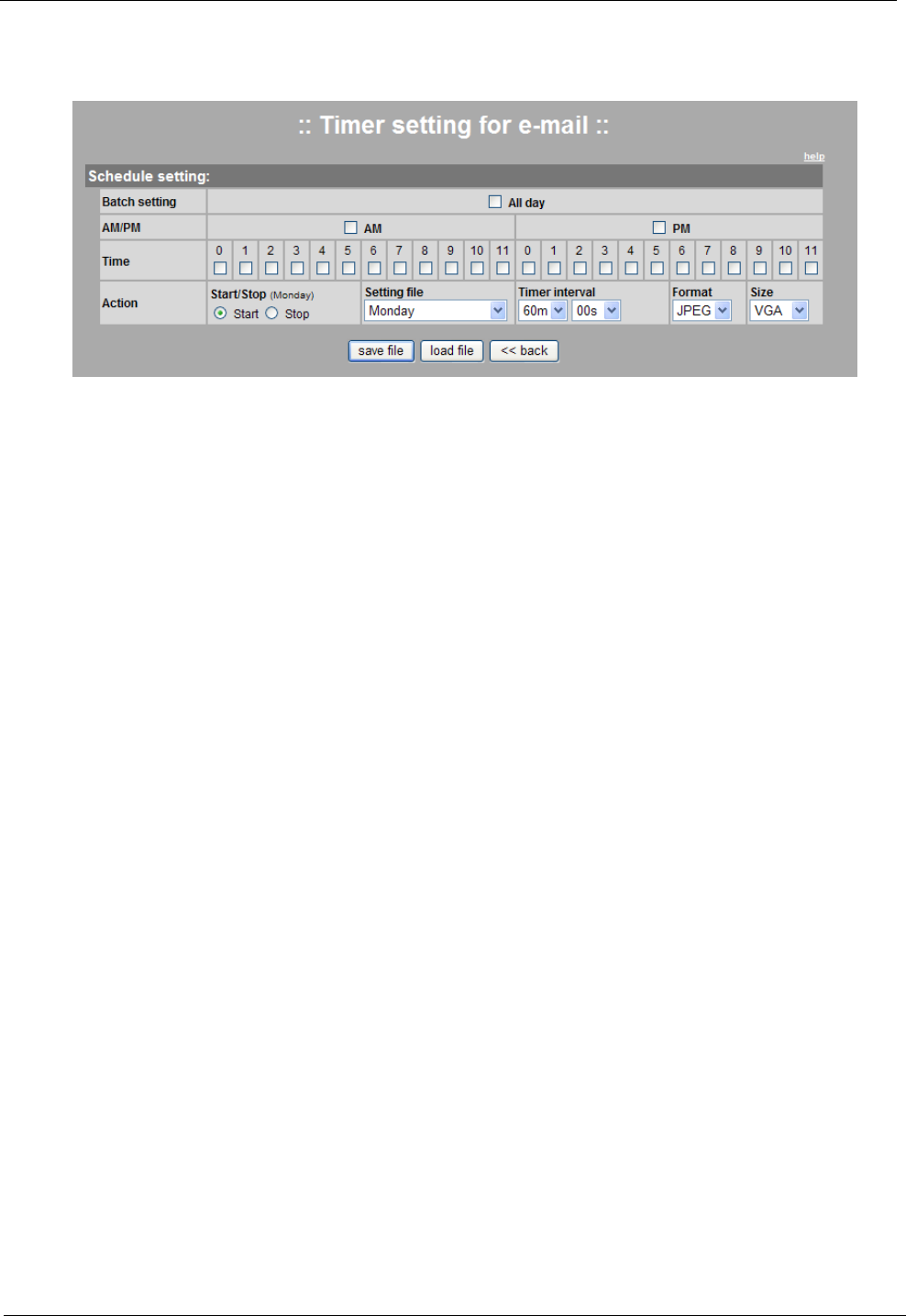
4-5-3. Setting for E-mail
This is a setup page in case that email is used for a scheduled transfer media.
Setting Instruction
nter all sections accurately and click the Save button.
Detail Setting for E-mail
To (receiver): Enter the e-mail address of a receiver. You can register up to 3 different addresses.
Sender: Enter the e-mail address to receive a reply from the receiver.
Title: Enter the title of the e-mail.
Sending contents/JPEG files: There are two different sending modes which are sending text messages and
sending JPEG files.
SMTP Server Setting
SMTP Server IP Address/Host Name: Enter the server name or IP address informed by SMTP server.
Port Number: Enter the port number of SMTP. (default 25)
Use of Authentication: If you need authentication of SMTP server, click the ‘Yes’ button.
Login ID/Password: If you need authentication of SMTP server, enter the account information.
Send E-mail Test
It is a trial sending by e-mail to check if the setting above is correct. Enter the e-mail address of the receiver
and click the “send” button.
Network Camera Web Application Manual
Ver. S1
20/30
4-5-4. Schedule setting
This page is for setting Schedule. It is possible to set for sending by E-mail, or saving on network shared
folder separately.
Setting Method
Input ID, password and select user group. After that, click the saving button.
Reference
Setting at the same time: Select/Cancel from 0 to 24 hrs together.
Morning/Afternoon: Select/Cancel morning/afternoon at the same time.
Time setting: Select/Cancel time in the unit on an hour basis.
Operation setting
Start/Stop: When saving, select the operation of Schedule schedule.
Setting file: You can save or open the daily schedule. It is possible to set the weekday/weekend/daily
schedule.
Timer interval: Set time interval of sending image.
Type: Format of sending image
Size: Size of sending image
Schedule save/Call function
Save Image: Click a save button for saving schedule of selected day on [Trigger setting>Schedule
Setting], and if in [Action>Start/Stop], the button is on the ‘Start’, the schedule sending is started. If the button
is on the ‘Stop’, schedule is only saved and the schedule on operation is stopped.
Load Image: Call the schedule of the day on Combo box [Trigger setting>Schedule Setting].
Network Camera Web Application Manual
Ver. S1
21/30
4-6 Dynamic DNS Service Setting (DDNS)
4-6-1. Overview
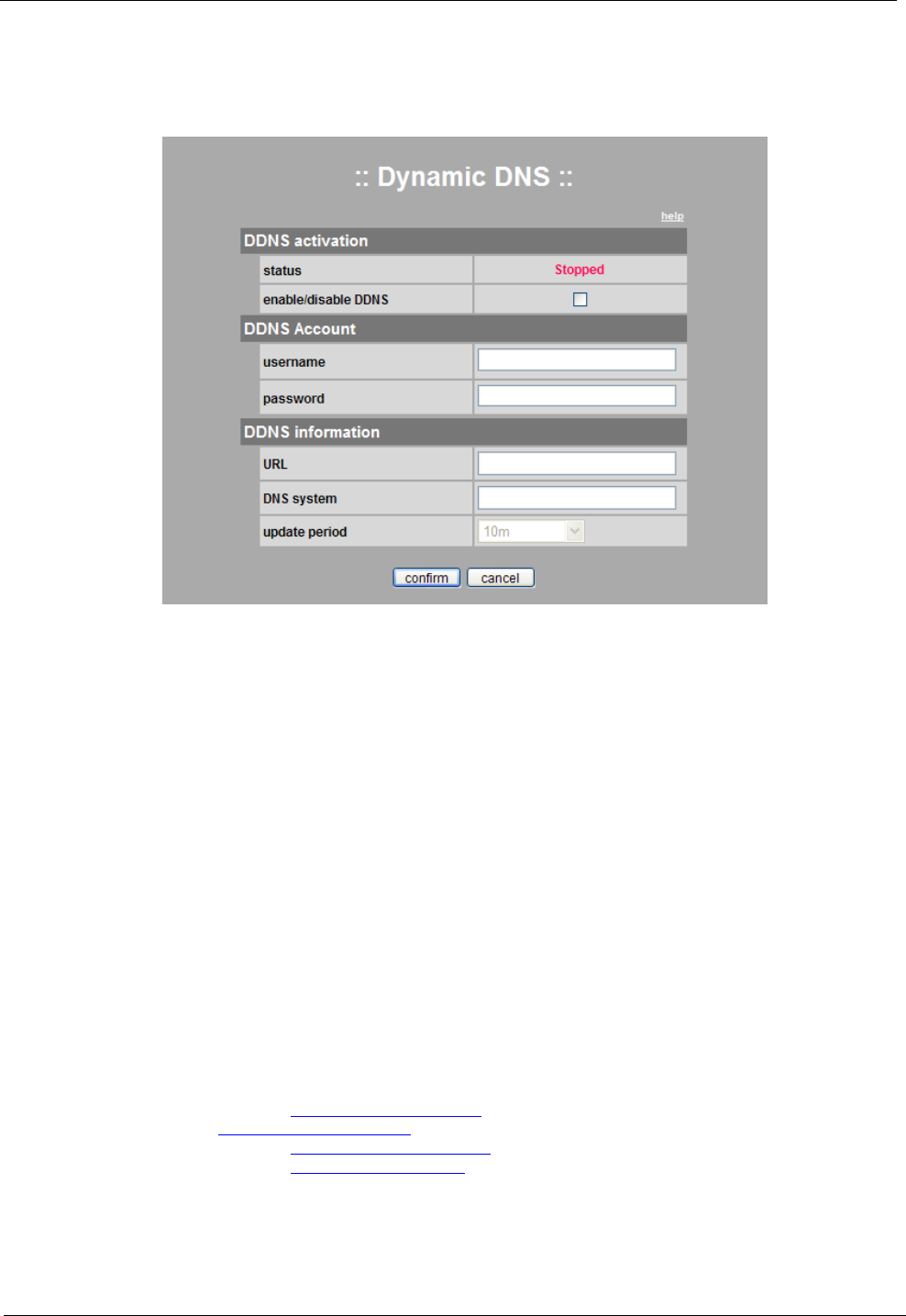
This is a page for setting up general DNS service. You need to subscribe for DDNS service.
4-6-2. Activating DDNS Service
Setting Instruction
Enter your ID and password in the DDNS Account, type in the registered URL and DNS system information in
the DDNS information, and then select the update period (between 10 minutes and 24 hours). If you click Confirm,
DDNS will be activated.
Check the enable/disable DDNS box.
Enter your ID and password registered when you joined a DDNS service site in the user name and password.
Enter a user’s URL registered in the DDNS site in URL.
For DNS system, refer to the content for DNS system informed by the DDNS service site and enter the
corresponding content.
Select the update period by referring to IP update period.
When all settings are complete, click Confirm to reflect the settings and initiate DDNS service.
Notice
The camera may not operate if the network setting of a camera or the input information is wrong, or there is
any problem in DDNS service. In this case, the service status will be displayed as ‘Stopped’ because DDNS service of
the camera cannot be operated.
Note
Supported main DDNS service sites
dyndns.org http://www.dyndns.org/
freedns.afraid.org http://freedns.afraid.org
zoneedit.com http://www.zoneedit.com
no-ip.com http://www.no-ip.com
Network Camera Web Application Manual
Ver. S1
22/30
4-7 Camera Maintenance
4-7-1. Overview
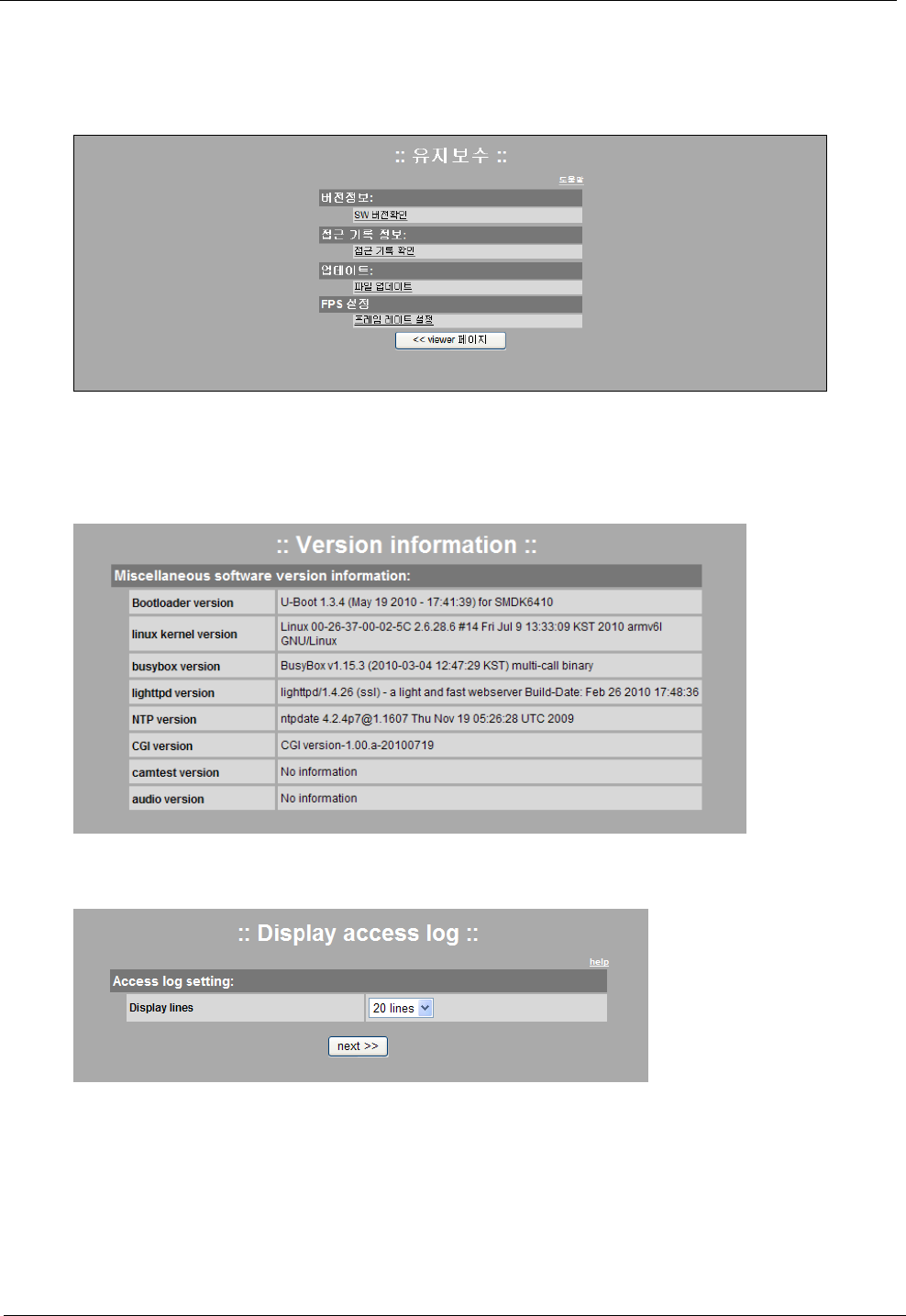
This page is allowed only to member s of maintenance. You can access to this page through separate URL
and certification process. There are four menus of version information check, access recording information, update,
frame rate setting.
4-7-2. Version Information
Version of interior software composing factors is displayed.
4-7-3. Access Log
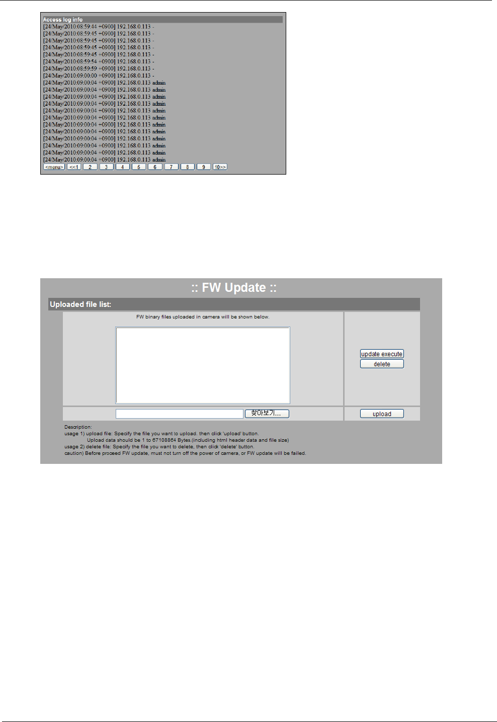
Access log of camera system is displayed. It is possible to set the line number indicating per page. When
clicking ‘Next’ button, the log is displayed.
Network Camera Web Application Manual
Ver. S1
23/30
On the log displaying page, you can check the log of the page by clicking the number of page. If there are
many logs, they are displayed by 10 pages. For going back to previous page, click the Menu button.
Order of displaying Access log
[DD/MM/YYYY:hh:mm:ss_Time]_IP Address_ Access ID
4-7-4. Update
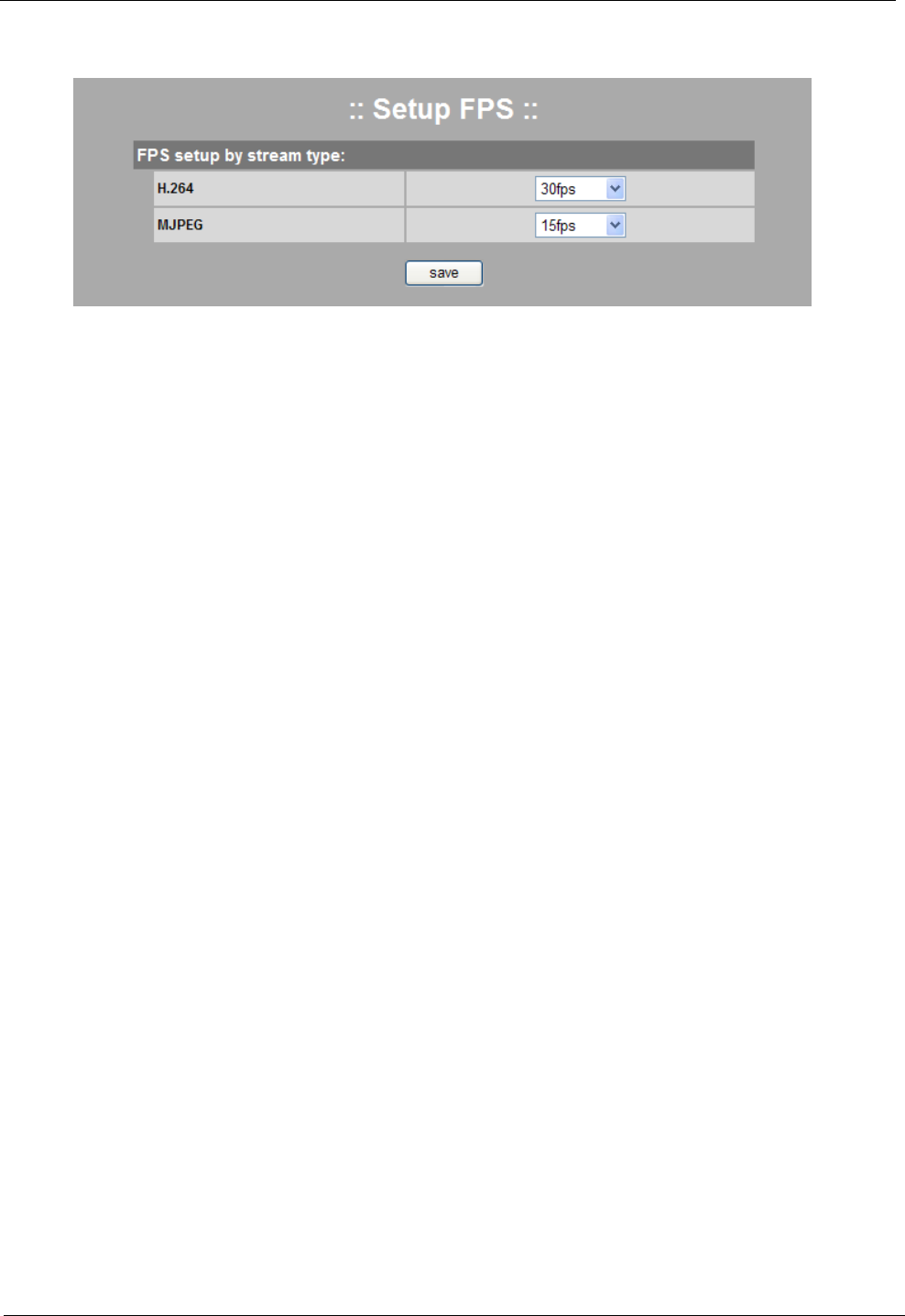
When update is needed, upload the package on camera and update.
* Operation method
(1) Click the ‘Search’ button for calling package file.
(2) Click the upload button for uploading updated package on camera
(3) When there is upload success message, and package is displayed on the list, click the update button.
(4) When update is finished, it is loaded again. Finally reset the camera.
Network Camera Web Application Manual
Ver. S1
24/30
4-7-5. Frame Rates Setup
It is possible to set the frame rate (fps: frames per second) by stream types.
Setting Instruction
Click the Save button after selecting fps to set. When the setting is saved, camera stream will be restarted;
therefore, please stop all connections before clicking the Save button.
MJPEG stream: It is possible to set the frame rate to 3, 5, 10 and 15fps.
H.264 stream: It is possible to set the frame rate to 10, 15 and 30fps.
Network Camera Web Application Manual
Ver. S1
25/30
5. Example: Changing Wired Connection to
Wireless Connection
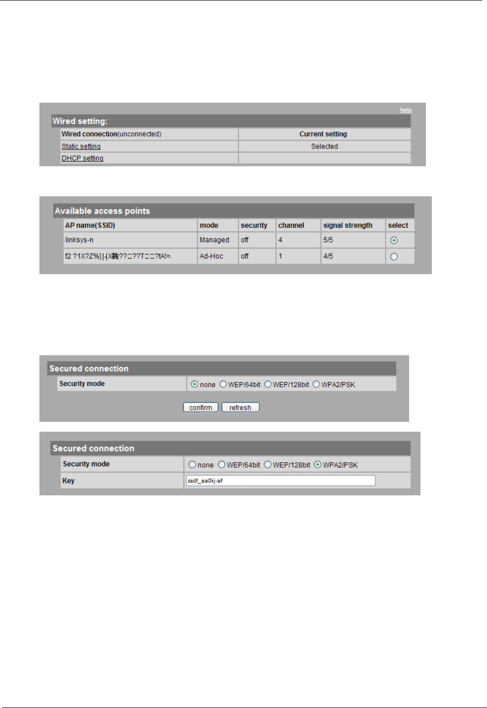
Preparation: Wireless AP
Check whether a camera is connected in wired network before changing to wireless connection.
Go to [Setup Page>Setup Network>Wireless] .
Check whether there is a connectable AP around a camera and select an AP that you want as shown in the
figure.
AP Security Activated: Select ‘none’ in the security mode and click Confirm to save the setting.
AP Security Deactivated: ‘on’ is displayed in the security mode. For AP security activated, select the security
mode and enter the authentication type and key correctly.
When you complete the settings, click Confirm to save the settings.
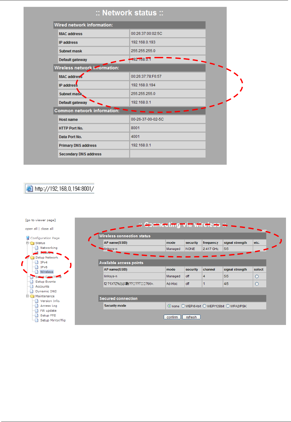
Go to [Setup Page>Status>Networking] and check an IP address.
Network Camera Web Application Manual
Ver. S1
26/30
Connect a camera to the address set in wireless network
.
When the connection is successful, check the connection status at
[Setup Page>Setup Network >Wireless].
Network Camera Web Application Manual
Ver. S1
27/30
6. Example: Setting External Internet
Connection (when using a router)
Preparation: an internet router which supports NAT setup (virtual server setup)
The following explains the method which can remotely connect to a camera by using an external internet.
This setup is limited to a personal internet router. If a network is connected to a local network router for
public use or you do not have authority for router setup, contact a network administrator.
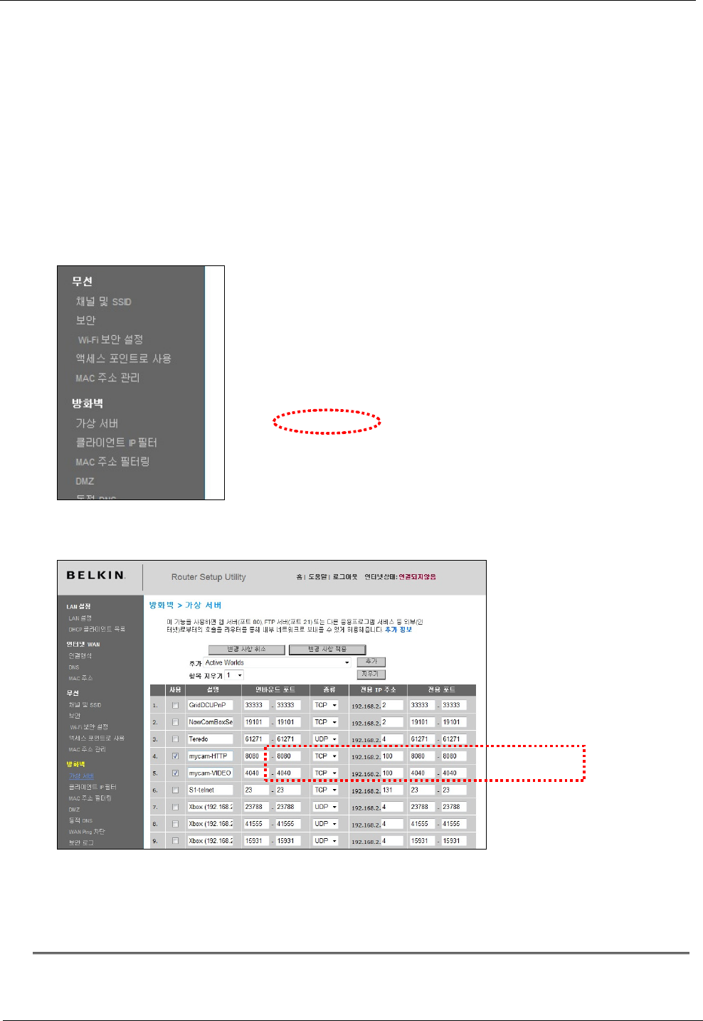
Router Setup
ccess the Router Setup Page. (Refer to Router Manual.) Go to the NAT setup (or virtual server setup) menu.
Add the IP and port information of a camera. (Please caution double setup not to collide with the existing
setup port. Set the port to the numbers between 49152 and 65535, if possible. )
It is necessary to add 2 items in the menu. Refer to the following table.
Item
IP Address Inbound
Port (Internal Port)
Outbound
Port
(External
Port)
Pr
otocol
Web Port
Local IP of a camera
For this example, it is
192.168.2.100
49152~65535 (It is
impossible to set
80 to inbound port)
49152~65535 (It is
impossible to set 80
to outbound port)
TCP
Network Camera Web Application Manual
Ver. S1
28/30
Image Port 49152~65535 49152~65535
Camera Setup
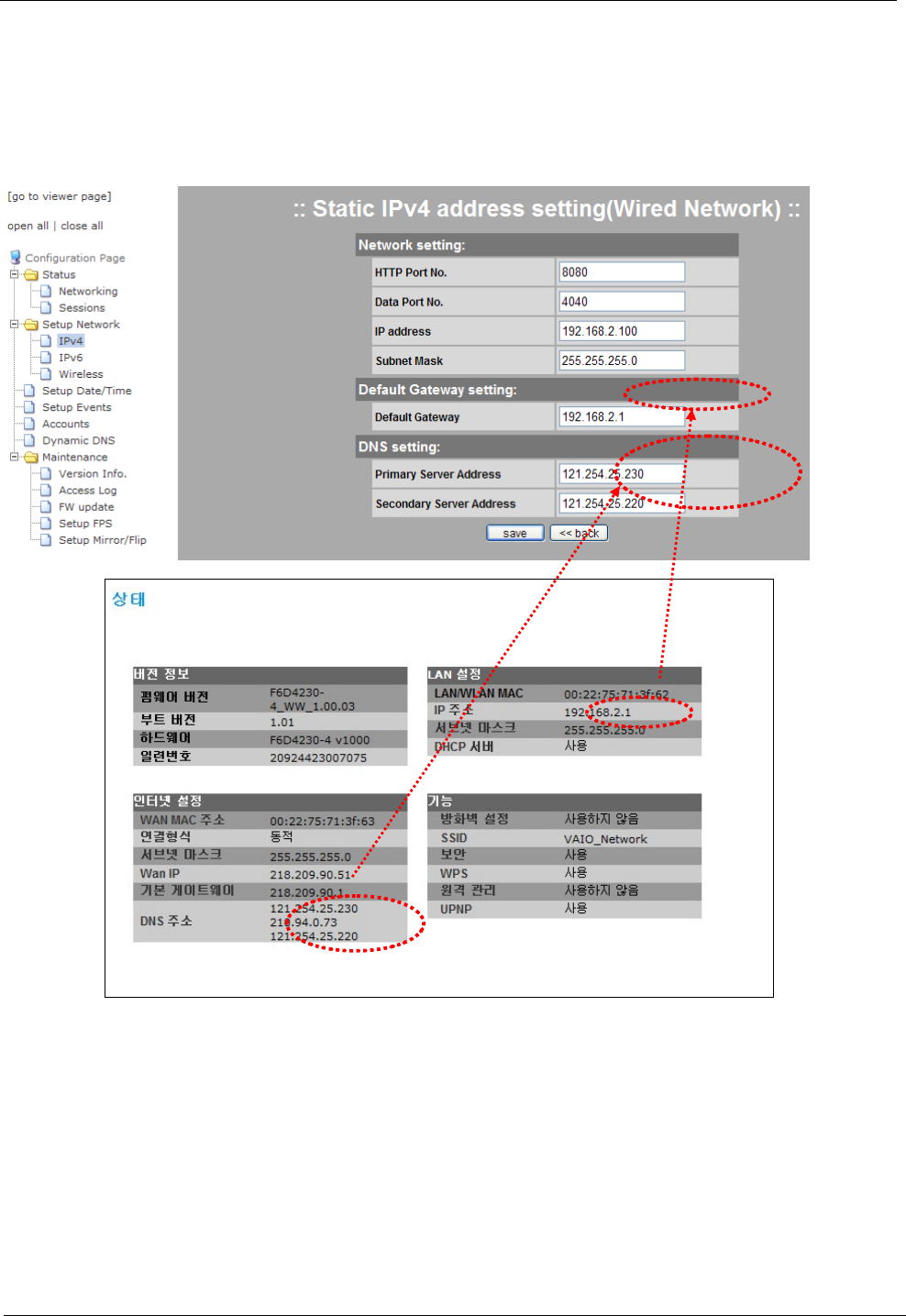
Go to [Setup Page>Setup Network>IPv4>Static Setting] .
Set the following necessary items by referring to the setup page of a router.
HTTP/Data Port Number: Verify whether HTTP/data port number are the same with those which have been
set in the router.
Basic Gateway: Enter the router IP.
DNS Server Address: Enter DNS server address by referring to the Setup page of the router. If there is a
single DNS server address, enter the main DNS only. If there are two or more DNS server addresses, it is allowed to
enter another DNS address in subsidiary DNS.
When you complete the settings, save it.
Access
For remote connection to a web browser, URL consists of an IP which is assigned by the internet service
provider of a router and HTTP port set in NAT.
Network Camera Web Application Manual
Ver. S1
29/30
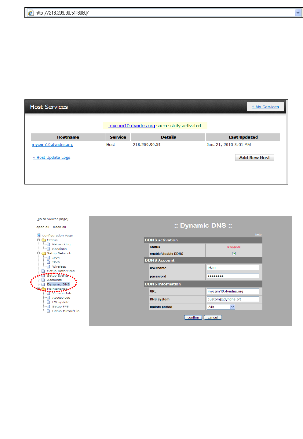
7. Example: Using Commercial DDNS
Service
Preparation: A DDNS service account, an assigned domain name and a camera which can access an external
internet
Access a DDNS service site and check whether an assigned domain name is valid and whether an IP is
properly set in the domain name.
The domain name is mycam10.dyndns.org and the assigned IP is 218.209.90.51. In this case, the IP is
assigned by an internet service provider. If you use a router, you should not use the local network IP of your router,
but you should register the IP assigned by an internet service provider to a DDNS service site.
Go to [Setup Page>Dynamic DNS Service]
.
In order to activate DDNS service, change the status that you can enter the form by checking the
[enable/disable DDNS] box.
Enter your ID and password registered in the DDNS service account.
For URL, enter the domain name assigned by the DDNS service account.
For DNS system, refer to the user’s guide in DDNS service site and enter the corresponding content.
For update period, if an IP is static, the update period should be 24 hours. If an IP is dynamic (DHCP), the
update period should be the same with or shorter than IP update period.
If you save by clicking the “confirm” button, DDNS service of the camera is activated. The activation is
displayed in [DDNS service status]. If the camera is turned off, DDNS service of the camera is terminated.
Connect via the following url address. When using a router, the port number is HTTP port which was already
set in the router. (It is set as 8080.)

Network Camera Web Application Manual
Ver. S1
30/30
Part 15.19
This device complies with part 15 of the FCC Rules. Operation is subject to the following
two conditions: (1) This device may not cause harmful interference, and (2) this device must
accept any interference received, including interference that may cause undesired operation.
Part 15.21
Any changes or modifications (including the antennas) made to this device that are not
expressly approved by the manufacturer may void the user's authority to operate the
equipment.
RF Exposure Statement
FCC RF Radiation Exposure Statement: This equipment complies with FCC RF radiation
exposure limits set forth for an uncontrolled environment. This device and its antenna must not
be co-located or operating in conjunction with any other antenna or transmitter.
Part 15.105
This equipment has been tested and found to comply with the limits for a Class B digital device,
pursuant to part 15 of the FCC Rules. These limits are designed to provide reasonable
protection against harmful interference in a residential installation.
This equipment generates, uses and can radiate radio frequency energy and, if not installed
and used in accordance with the instructions, may cause harmful interference to radio
communications. However, there is no guarantee that interference will not occur
in a particular installation. If this equipment does cause harmful interference to
radio or television reception, which can be determined by turning the equipment off and
on, the user is encouraged to try to correct the interference by one or more of the following
measures:
—Reorient or relocate the receiving antenna.
—Increase the separation between the equipment and receiver.
—Connect the equipment into an outlet on a circuit different from that to which the receiver
is connected.
—Consult the dealer or an experienced radio/ TV technician for help.
FCC RF Radiation Exposure Statement
The antenna(s) used for this transmitter must be installed to provide a
separation distance of at least 20 cm from all persons and must not be
co-located or operation in conjunction with any other antenna or
transmitter.