Polvac Kashiyama All Pumps
User Manual: Polvac Kashiyama All Pumps
Open the PDF directly: View PDF ![]() .
.
Page Count: 12

e-catalogSDEJVer2.1/06.6
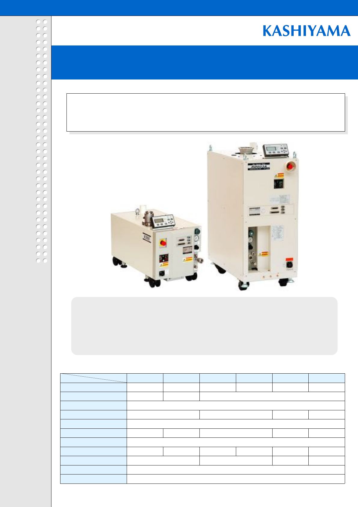
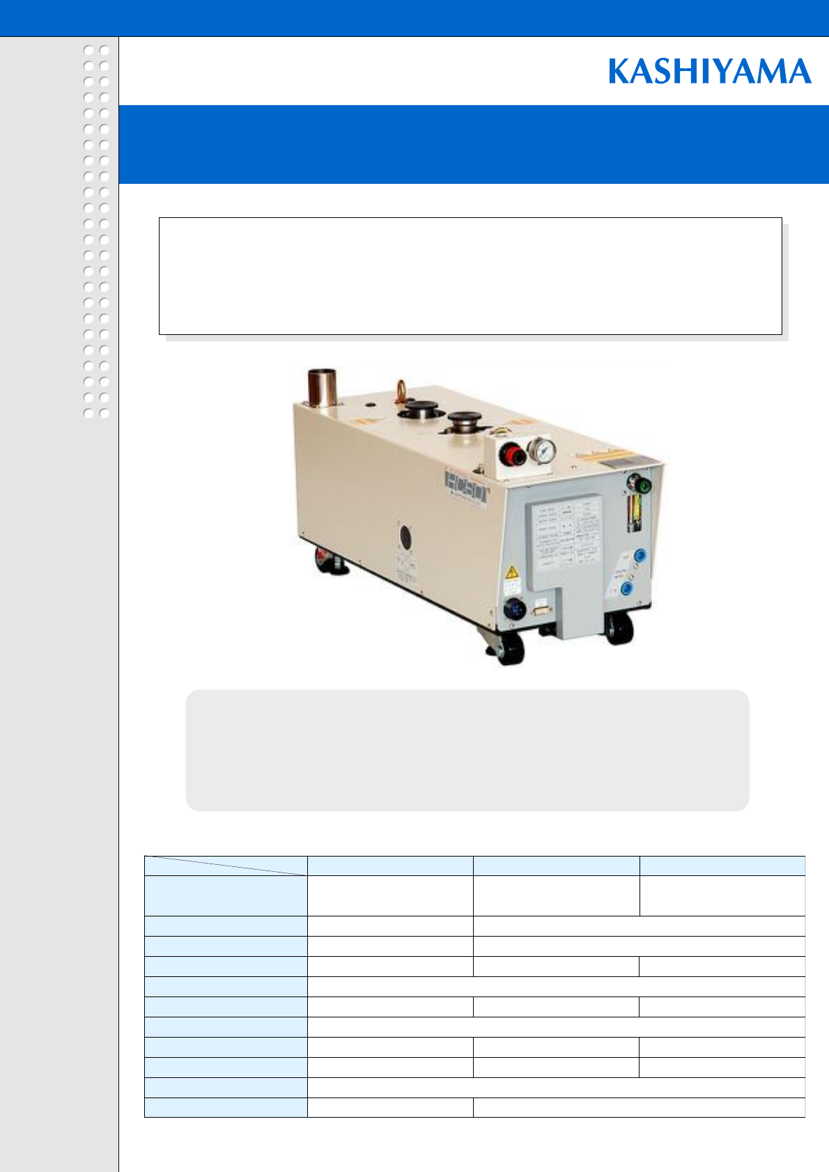
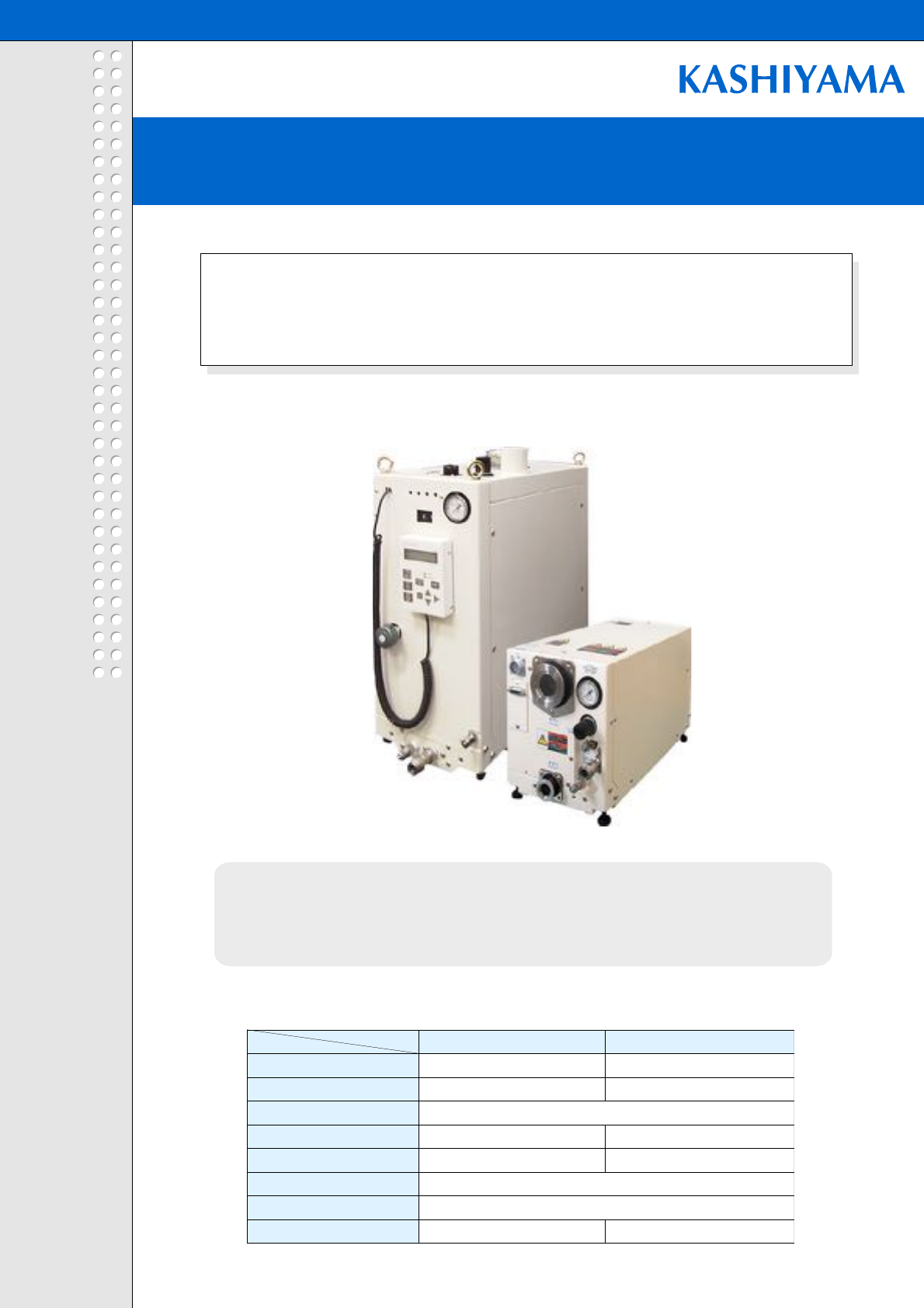
Dry pumps reliable for all applications.
Energy-saving features combine with the reliability, SDE Series
achieved lower running cost.
- Advanced screw technology allows longer life operation under hard applications.
- Anti-corrosion material construction allows pumping of corrosive gasses.
- Upgraded screw design and driving system realized 40% reduction in energy
consumption, compared to conventional models.
SDE
SDE Series
Screw Dry Pump
SCREW DRY PUMP SDE SERIES
SCREW DRY PUMP SDE SERIES
Specification Table
Model
Specification SDE90 SDE120 SDE303 SDE603 SDE1203 SDE2003
Maximum Pumping Speed (L/min)
30,000
Ultimate Pressure (Pa)
Maximum Inlet Pressure (Pa)
Inlet Flange NW40 NW50 NW100 NW160
Outlet Flange
Weight(Approx.) (kg) 150 151 260 260 310 470
Electric Power Supply
Power in normal operation (kW)*
2.8 3.2 3.0 3.1 3.6 4.0
Electric Power Capacity (kVA)
6.5 10.5 13.0 17.6
Cooling Water Supply
Purge N2Gas Supply 0-60SLM
NW80
NW40
3phaseAC200-220V50/60Hz
4L/min and over
20,000
1.3 0.5
Atmospheric pressure
1,300 2,000 5,000 10,000
* Power at ultimate pressure.
KASHIYAMA IND., LTD.
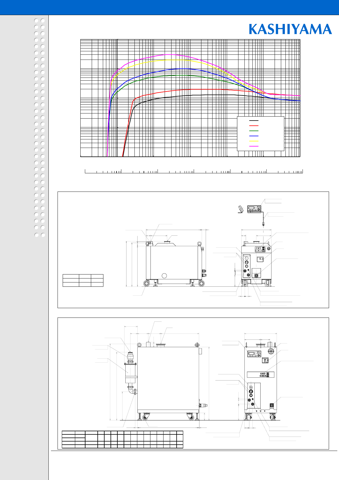
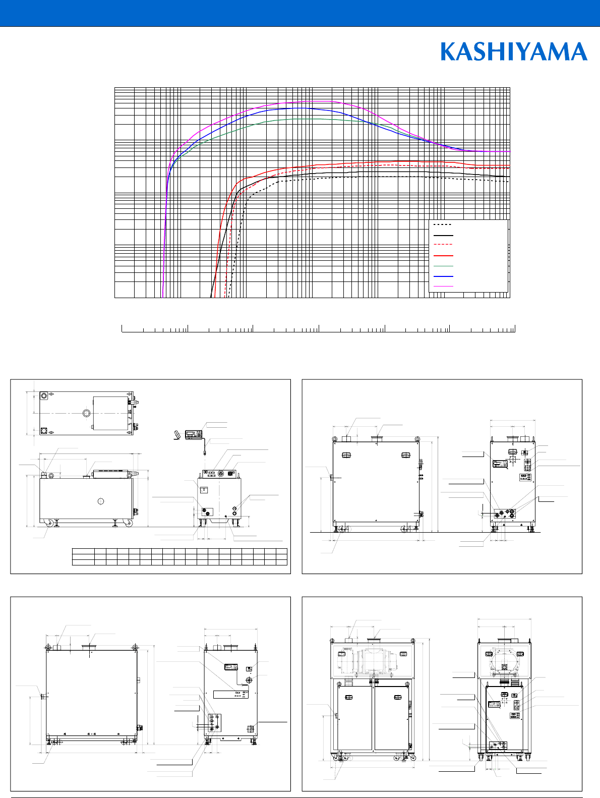
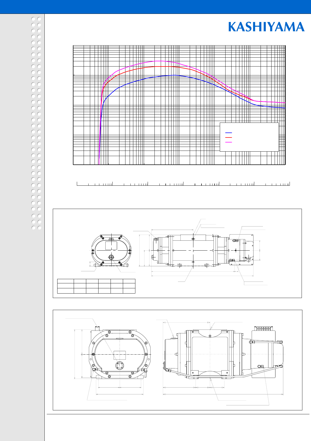
Pumping Curve(SP)
Pump Schematics (SDE90,SDE120)
Pump Schematics (SDE303,SDE603,SDE1203,SDE2003)
Note 1) Because we are constantly working to improve performance and upgrade our
products, specifications and diagrammatic representations in this catalog may change
without notice.
Note 2) Products displayed in this catalog must be approved for export in accordance with
the Foreign Exchange and Foreign Trade Control Act. Before placing an export order,
please contact our Business Department.
-Dry vacuum Pump
-Mechanical Booster Pump
-Air Discharge System
URL:www.kashiyama.co.jp/
mail address for inquiries:
sales@kashiyama.co.jp
KASHIYAMA IND., LTD.
e-catalogSDEJVer2.1/06.6
SDE
SCREW DRY PUMP SDE SERIES
SCREW DRY PUMP SDE SERIES
NW 50
NW 40
InletModel
S
DE120
S
DE90 551
560
H
Dimens ion:mm
ELCB
N2pres s ure gauge
Powerconnector
CasterwithPIPE-FITTING 1/4 stra ight
C ooling waterinlet
R
c3/8
withself-sealcoupler
withself-sealcoupler
N2supply port
C ooling wateroutlet
R
c3/8
DuctO D5 0
O utletNW 40
Inlet
N2controlvalve
R
egulator
EMO
R
emote controlconnector
C ontrolpanel
C ommunication cable
(
L=2000mm
)
170*80*30
540
(
O utlet
)
501
H
(
Inlet
)
(
50
)
4244
143 1350
690
54
55 205
370
65 185
N2controlvalve
O utletNW 40 Caster
C ooling wateroutlet
R
c3/8
C ooling waterinlet
R
c3/8
N2supply port
withself-sealcoupler
withPIPE-FITTING 1/4 stra ight
withself-sealcoupler
N2pres s ure gauge
R
egulator
Powerconnector
O utletNW 40
Duct
Inlet
(
OPTIO N
)
(
OPTIO N
)
S
ilencer
C heckvalve
C ontrolpanel
170*80*30
ELCB
R
emote controlconnector
EMO
H
B
(
O utlet
)
A
(
Inlet
)
D
C
(
O utlet
)
(
28
)
g42
f
(
8
)
(
90
)
50 13
(
c
)
60
ba
(
89
)
(
163
)
ed
W
10
100
1000
10000
100000
0.1 1 10 100 1000 10000 100000
Pressure(Pa)
Pumping Speed(L/
1000
Pressure (Torr)
100
10
1
0.1
0.01
0.001
SDE90
SDE120
SDE303
SDE603
SDE1203
SDE2003
Mode lInletDuctD W H A BCab c d e fg
S
DE303 NW 50
S
DE603 NW 80
S
DE1203 NW 100 O D 50 900 400 906 945 841 352 195 155 550 200 115 200 59
S
DE2003 NW 160 O D 75 1000 500 1090 1165 850 360 155 195 650 250 135 208 108
200
59
155
472
200
115
O D 50
760
400
906
945
841
352
133
KASHIYAMA IND., LTD.
e-catalogRDJVer2.1/06.6
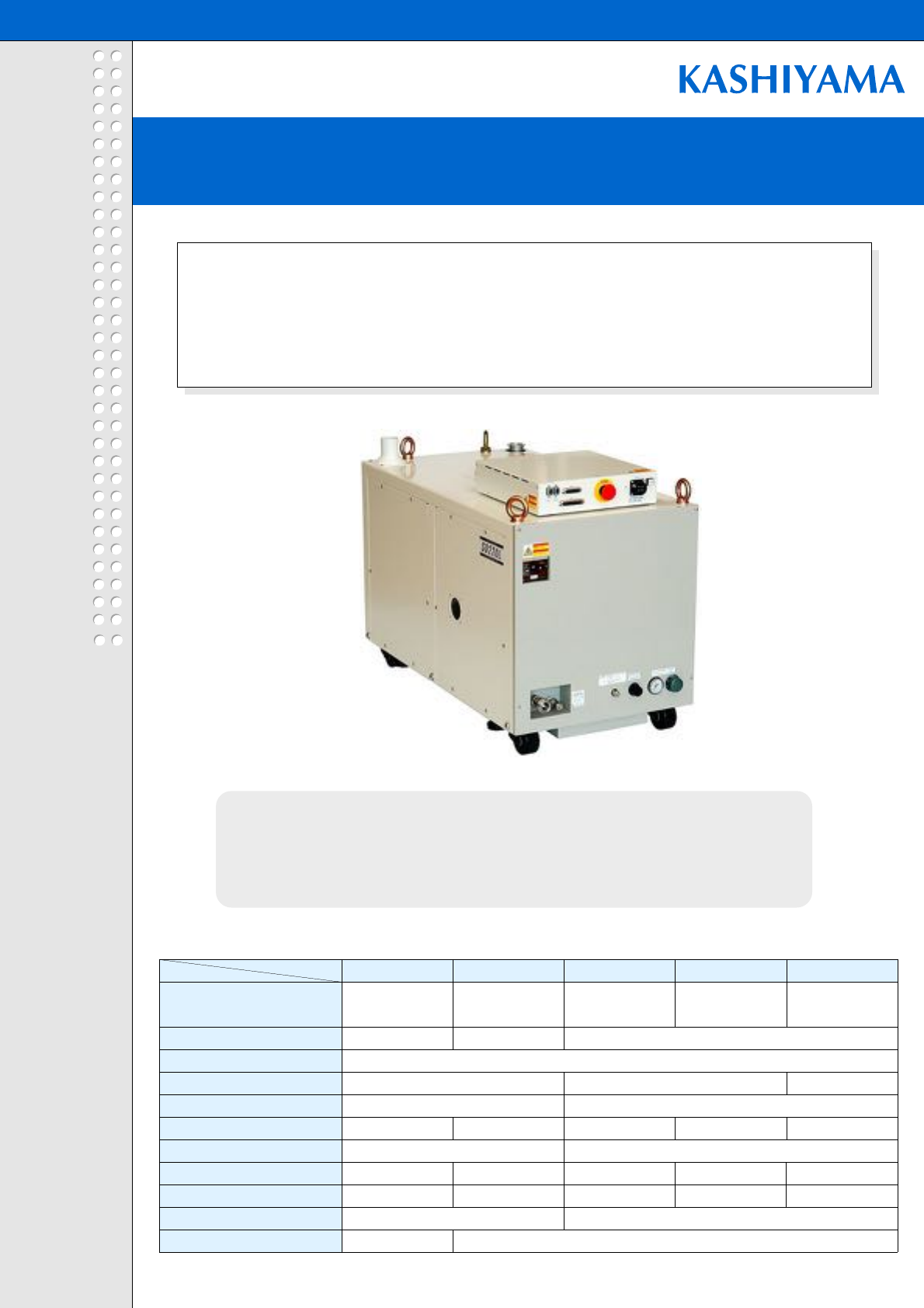
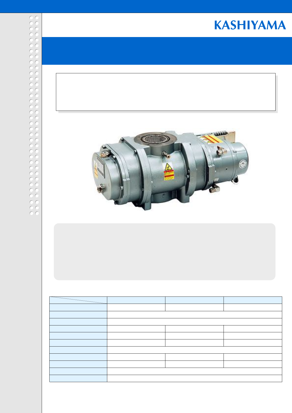
New lower running cost pump for light to medium applications.
RD achieves significant improvements in environmental performance by
innovative power-saving technology.
- Multistage configuration optimizes pumping efficiency, minimizes power consumption.
- Applicable from light processes such as load rock and transfer, to etching and other medium
processes.
- Upgraded roots element and driving system realized 70% reduction in energy consumption,
compared to conventional models.(RD90)
RD
RD Series
Roots Dry Pump
Specification Table
Model
RD90(RDE90)
RD120 RD303 RD603 RD1203
Maximum Pumping Speed (L/min)
1,300 2,000 5,000 10,000 20,000
Ultimate Pressure (Pa)
Maximum Inlet Pressure (Pa)
Inlet Flange
NW40 NW80 NW100
Outlet Flange
Weight(Approx.) (kg)
130 140 240 300
Electric Power Supply
Power in normal operation (kW)*
1.3 (0.65) 1.7 1.5 1.6 1.7
Electric Power Capacity (kVA)
4.0 8.0 10.5
RD2003
30,000
NW160
475
2.1
15.1
Cooling Water Supply
Purge N2Gas Supply
2.7 2.0 0.5
Atmospheric pressure
NW40
3phaseAC200-220V50/60Hz
3.5L/min and over
0-50SLM
Specification
ROOTS DRY PUMP RD SERIES
ROOTS DRY PUMP RD SERIES
*Power at ultimate pressure.
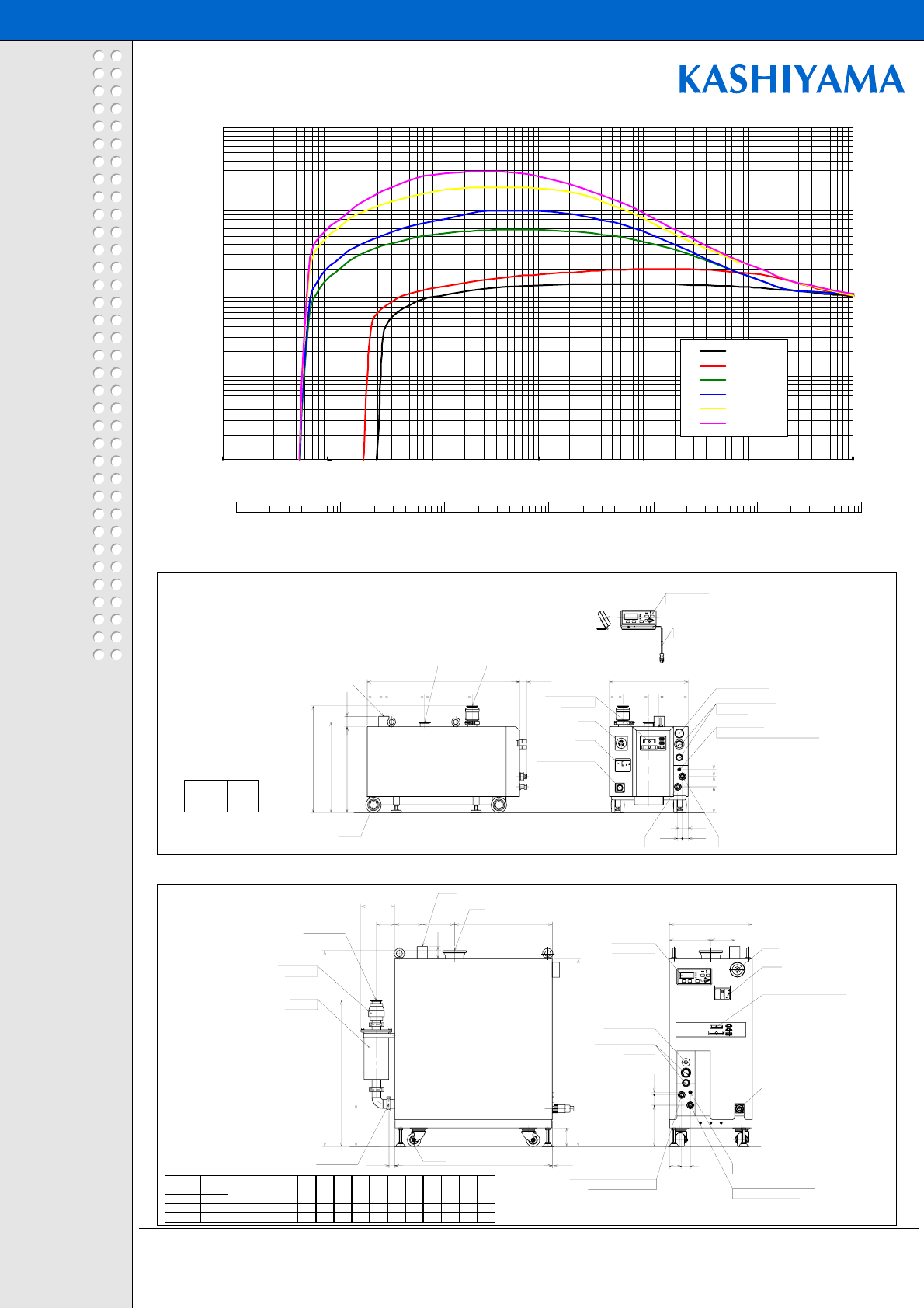
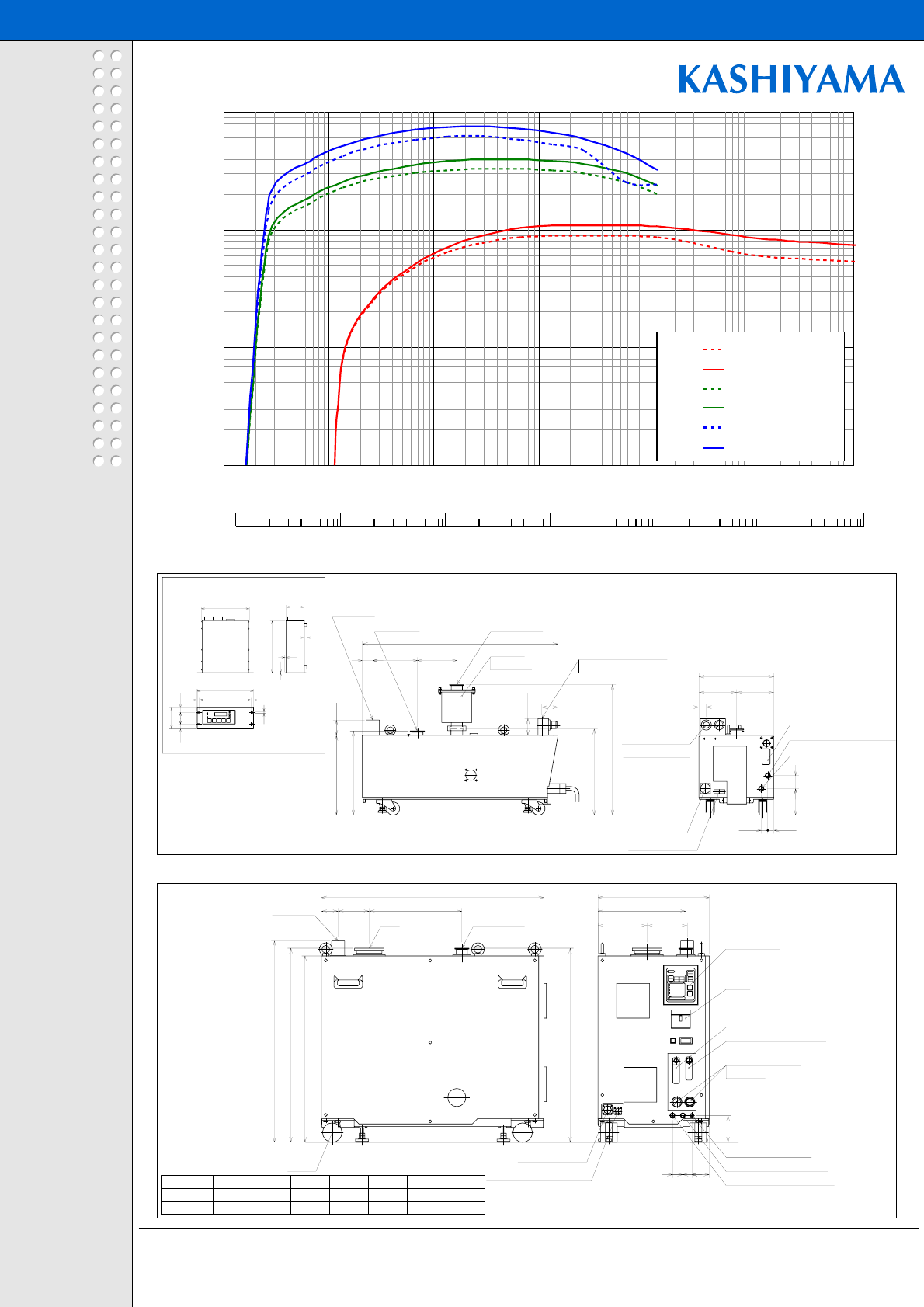
Pumping Curve(SP)
Pump Schematics (RD90,RD120)
Pump Schematics (RD303,RD603,RD1203,RD2003)
Note 1) Because we are constantly working to improve performance and upgrade our
products, specifications and diagrammatic representations in this catalog may change
without notice.
Note 2) Products displayed in this catalog must be approved for export in accordance with
the Foreign Exchange and Foreign Trade Control Act. Before placing an export order,
please contact our Business Department.
-Dry vacuum Pump
-Mechanical Booster Pump
-Air Discharge System
URL:www.kashiyama.co.jp/
mail address for inquiries:
sales@kashiyama.co.jp
KASHIYAMA IND., LTD.
e-catalogRDJVer2.1/06.6
RD
ROOTS DRY PUMP RD SERIES
ROOTS DRY PUMP RD SERIES
735
R
D90
785
R
D120
ModelL
Dimens ion:mm
ELCB
N2pres s ure gauge
N2supply port
Caster
withself-sealcouplerwithself-sealcoupler
C ooling waterinlet
R
c3/8
Powerconnector
C ooling wateroutlet
R
c3/8
InletNW40
DuctO D 50
O utletNW40
R
emote control
connector
EMO
R
egulator
N2controlvalve
withPIPE-FIT T ING 1/4 stra ight
C ommunication cable
(
L=2000mm
)
170*80*30
C ontrolpanel
33
(
35
)
415
437
(
Inlet
)
515
(
O utlet
)
125
43
2822
50
230
L
80 197
50
50
380
65 140
N2controlvalve
S
ilencer
O utletNW40 Caster
C ooling wateroutlet
R
c3/8
C ooling waterinlet
R
c3/8
N2supply port
withself-sealcoupler
withPIPE-FITTING 1/4 stra ight
withself-sealcoupler
N2pres s ure gauge
R
egulator
Powerconnector
O utletNW40
Duct
Inlet
(
OPTIO N
)
(
OPTIO N
)
C heckvalve
C ontrolpanel
170*80*30
ELCB
R
emote controlconnector
EMO
H
(
163
)
B
(
O utlet
)
A
(
Inlet
)
D
C
(
O utlet
)
(
28
)
g42
f
(
8
)
(
90
)
50 13
(
c
)
60
ba
(
89
)
ed
W
10
100
1000
10000
100000
0.1 1 10 100 1000 10000 100000
Pressure(Pa)
RD90
RD120
RD303
RD603
RD1203
RD2003
1000
Pressure (Torr)
100
10
1
0.1
0.01
0.001
Pumping Speed(L/min)
Mode lInletDuctD W H A BCab c d e fg
R
D303 N W 50
R
D603 N W 80
R
D1203 NW 100 O D 50 900 400 906 945 705 206 195 155 550 200 115 200 59
R
D2003 NW 160 O D 75 1000 500 1090 1165 704 214 155 195 650 250 135 208 108
200
59
155
472
200
115
O D 50
760
400
906
945
705
206
133
e-catalogSDLJVer2.1/06.6
- Maximized the pumping speed in the atmospheric side to achieve higher
throughput.
- The combination with large booster pump allows higher pumping speed up to
35,000L/min.
- Applicable for clean processes.
SDL
SDL Series
High Throughput Dry Pump
SCREW DRY PUMP SDE SERIES
SCREW DRY PUMP SDE SERIES
Higher pumping speed.
Support larger diameter wafer and larger FPD substrate applications.
Higher pumping speed minimizes the tact time for large load lock
chamber.
Specification Table
Model
Specification
Maximum Pumping Speed (L/min)
(Upper 50Hz / Lower 60Hz)
Ultimate Pressure (Pa) 50/60Hz
Maximum Inlet Pressure (Pa)
Inlet Flange
Outlet Flange
Weight(Approx.) (kg)
Electric Power Supply
Power in normal operation (kW)
Electric Power Capacity (kVA)
Cooling Water Supply
Purge N2Gas Supply
5L/min and over
0-50SLM0 or 8SLM
Atmospheric pressure
3phaseAC20050/60Hz AC220V60Hz
KASHIYAMA IND., LTD.
6L/min and over
3phaseAC200-220V50/60Hz
SD150L SD220L SDL25K SDL40K
2,000 3,100 25,000
2,400 3,700
4/2 4/3 0.5
NW50 NW100 NW160
325 450 620 910
3.6 5.0
6.1 8.3
NW40
SDL60K
40,000 55,000
6.9
17.0
7.0
23.6
7.4
28.1
NW50
750
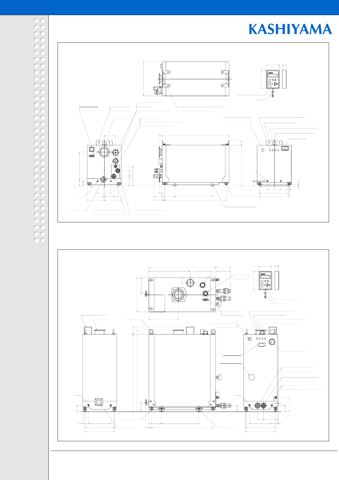
Pumping Curve(SP)
Pump Schematics
e-catalogSDLJVer2.1/06.6
SDL
*1:The pres s ureregulatorlayoutva riesfrom the diagra minthe
S
D150L a nd
S
D220Lmodels .
W2
S
D150L
S
D220L
Model
950
960
L1
492
606 72
60
H1 H2
661
626
518
630
H3 H4
432
402
L3
43
41
L2
440
524
43
45
W1
177
217
43
62
W3 W 4
67
74
35
57
ab
184
152
135
130
c d
109
143
35
15
ef
Dime ns ion:mm
EMO
R
emote controlconne c tor
Powerconnector
DuctO D 50
InletNW50
O utletN W 40
Caster
C oo ling wateroutlet
R
c3/8 N2 pres s ure gauge
C oo ling waterinlet
R
c3/8
withself-sealcoupler
N2 supply port
withPIPE-FIT T ING 1/4 stra ight
ELCB
withself-sealcoupler
R
egulator
170*80*30
C on trolpane l
C om munication c able
(
L=2000mm
)
(
46
)
L3
H2
L2
L1
H3
(
Inlet
)
H4
(
O utlet
)
H1
e
ab
d
c
f
85
W2
W1
W4 W3
*1
Note 1) Because we are constantly working to improve performance and upgrade our
products, specifications and diagrammatic representations in this catalog may change
without notice.
Note 2) Products displayed in this catalog must be approved for export in accordance with
the Foreign Exchange and Foreign Trade Control Act. Before placing an export order,
please contact our Business Department.
-Dry vacuum Pump
-Mechanical Booster Pump
-Air Discharge System
URL:www.kashiyama.co.jp/
mail address for inquiries:
sales@kashiyama.co.jp
KASHIYAMA IND., LTD.
10
100
1000
10000
100000
0.1 1 10 100 1000 10000 100000
Pressure(Pa)
Pumping Speed(L/min
SD150L(50Hz)
SD150L(60Hz)
SD220L(50Hz)
SD220L(60Hz)
SDL25K
SDL40K
SDL60K
Pressure (Torr)
100
10
1
0.1
0.01
0.001 1000
SD150L,SD220L
EMO
InletNW100
1000
Inlet1110
27
O utlet633
Caster
O utletN W 50
DuctportO D 50
60
355155
C on trolpane l
ELCB
1050
N2supply port
C oo ling waterInlet
R
c1/2
C oo ling waterO utlet
R
c1/2
5080
182
13
(
44
)
Pipe fitting 1/4
withself-sealcoupler
170*80*30
40
EMO
R
egulator
N2pres s ure gauge
N2controlvalve
R
emote controlconnector
Powerconnector
520
260 140
withself-sealcoupler
30
Pipe fitting 1/4
withself-sealcoupler
C ooling waterO u tlet
R
c1/2
C ooling waterInlet
R
c1/2
1250
Inlet1315
1200
Caster
65
O utlet633
O utletN W50
(
72
)
424
Duc tportO D 50
141 InletNW160
60
R
emote c ontrolconnector
C on trolpane l
ELCB
EMO
Powerconne ctor
30
100 70
30
N
2supply port
N
2pres s ure gauge
N
2controlvalve
207
R
egulator
170
700
170*80*30
180
withself-sealcoupler
EMO
C ooling waterInlet
R
c1/2
withself-sealcoupler
C on trolpane l
1660
Inlet1720
1180
O utlet633
Caster
O utletN W50
Duc tportO D 50
355255 InletNW160
60
EMO
R
emote c ontrolconne ctor
Powerconne ctor
ELCB
Pipe fitting 1/4
N2supply port
80
182
N2controlvalve
N
2pres s ure gauge
R
egulator
170*80*30
375
750
140
C ooling waterO u tlet
R
c1/2
withself-sealcoupler
13
30
80
50
40
SDL25K
SDL40K SDL60K
KASHIYAMA IND., LTD.
e-catalog HCJ Ver1.1/06.6
All-purpose dry pump.
High performance and low cost together in a compact, lightweight
package.
Smaller footprint enables easy installation anywhere.
- Innovative horizontal screw configuration in a compact design
- Lightweight aluminum construction.
- Applicable from light processes such as load rock and transfer, to
light etching processes.
HC
HC Series
Light Conpact Dry Pump
LIGHT CONPACT DRY PUMP HC SERIES
LIGHT CONPACT DRY PUMP HC SERIES
Specification Table
Specification HC60A/B HC250 HC450
Maximum Pumping Speed (L/min)
900 3,300 6,300
(Upper 50Hz / Lower 60Hz) 1,100 4,000 7,600
Ultimate Pressure (Pa) 1
Maximum Inlet Pressure (Pa)
Inlet Flange NW50 NW80
Outlet Flange
Weight(Approx.) (kg) 77 160 195
Electric Power Supply
Power in normal operation (kW)
Electric Power Capacity (kVA)
3.0 5.1 5.8
2.1 2.5 2.9
Cooling Water Supply
Purge N2Gas Supply (Type B only)
0-12SLM12SLM
NW40
3phaseAC20050/60Hz AC220V60Hz
3.5L/min and over
0.5
Atmospheric pressure 1,300
NW40
Model
Pumping Curve(SP)
Pump Schematics (HC60)
Pump Schematics (HC250,HC450)
Note 1) Because we are constantly working to improve performance and upgrade our
products, specifications and diagrammatic representations in this catalog may change
without notice.
Note 2) Products displayed in this catalog must be approved for export in accordance with
the Foreign Exchange and Foreign Trade Control Act. Before placing an export order,
please contact our Business Department.
-Dry vacuum Pump
-Mechanical Booster Pump
-Air Discharge System
URL:www.kashiyama.co.jp/
mail address for inquiries:
sales@kashiyama.co.jp
KASHIYAMA IND., LTD.
e-catalog HCJ Ver1.1/06.6
HC
LIGHT CONPACT DRY PUMP HC SERIES
LIGHT CONPACT DRY PUMP HC SERIES
Dimension:mm
Inlet L3L1 L2Model
NW80HC450
HC250 NW50
120860 358
105750 265
W3W2W1
340190430
160400 315
Cooling water flow meter
N2flow meter
Caster Cooling water inletRc3/8
Cooling water outletRc3/8
Remote controlconnector
Power connector N2supply port R c1/4
N2pres s ure gauge
Regulator
Duct OD50
Inlet Outlet NW40
ELCB
Control panel
720
750 (Inlet)
778
750 (Outlet)
673540
104
L1
L3
65 L2
W1
W3
W2 155
745
170
Controller PC100
20
11
222
240
90
6
2050
22010 10
5
2
204
78
Outlet NW40
(OP TION)
Silencer
Inlet NW40
Duct OD50
Cooling water flow meter
Coolin water outletRc3/8
Regulator forN
2
Cooling water inlet Rc3/8
Signalconnector
Power connector
(attached to Type B)
N2supply port R c1/4
(attached to Type B)
(63)
328 (Outlet)
497 (Outlet)
304
40
320 (Inlet)
150
58
285
142.5142.5
(28)
25 23
50100
(63)
10
100
1000
10000
0.1 1 10 100 1000 10000 100000
Pressure(Pa)
Pumping Speed(L/min)
HC60(50Hz)
HC60(60Hz)
HC250(50Hz)
HC250(60Hz)
HC450(50Hz)
HC450(60Hz)
1000
Pressure (Torr)
100
10
1
0.1
0.01
0.001
e-catalog KMBJ Ver2.0/04.6
- High efficiency motor and driving system realized significant downsize compare to
conventional models.
-Cannedmotorisadaptedtoimprovereliability.
- Improvements of the driving system and mechanical efficiency allow minimizing the power.
- Rotation speed control achieves continuous operation under the atmospheric pressure.
- Synchronous motor enables consistent pumping performance at any power supply
frequency. (03 series)
KMB
KMB Series
Booster Pump
BOOSTER PUMP KMB SERIES
BOOSTER PUMP KMB SERIES
Can be used in combination with the dry pumps to enhance pumping
capacity.
Rotational speed control enables operation from atmospheric
pressure.
Specification Table
KMB603 KMB1203 KMB2003
Maximum Pumping Speed (L/min)*
30,000
Ultimate Pressure (Pa)*
Maximum Inlet Pressure (Pa)
Inlet Flange VG80 VG100 VG150
Outlet Flange VF65 VF100 VF150
Weight(Approx.) (kg) 85 110 230
Electric Power Supply
Power in normal operation (kW)**
0.3 0.4 0.8
Electric Power Capacity (kVA)
6.5 11.1
Cooling Water Supply
Purge N2Gas Supply
*The values shown here represent operation in combination with the dry pump as recommended by Kashiyama.
10,000 20,000
0.5
0 or 20SCCM
Atmospheric pressure
3phaseAC200-220V 50/60Hz
4.0
3L/min and over
Specification Model
**Power at ultimate pressure.
KASHIYAMA IND., LTD.
Pumping Curve(SP)
Pump Schematics (KMB603,KMB1203)
Pump Schematics (KMB2003)
e-catalog KMBJ Ver2.0/04.6
KMB
BOOSTER PUMP KMB SERIES
BOOSTER PUMP KMB SERIES
Dimens ion:mm
VF100 607.5 305746KMB1203 V G 100
V G 80
Inlet
KMB603
Model
VF65
O utlet
596 457.5
L1L2
230
L3
Oil dra in plug
Inlet
withPIPE-FIT T ING 3/8
C ooling waterO utlet
withPIPE-FIT T ING 3/8
C ooling waterinlet
O utlet
Oil levelgauge
Oil s upply plug
withPIPE-FIT T ING 1/4
N2supply port
32
230
114
(
Inlet
)
L3
L2
L1
116
113
(
O utlet
)
27
7272
Note 1) Because we are constantly working to improve performance and upgrade our
products, specifications and diagrammatic representations in this catalog may change
without notice.
Note 2) Products displayed in this catalog must be approved for export in accordance with
the Foreign Exchange and Foreign Trade Control Act. Before placing an export order,
please contact our Business Department.
-Dry vacuum Pump
-Mechanical Booster Pump
-Air Discharge System
URL:www.kashiyama.co.jp/
mail address for inquiries:
sales@kashiyama.co.jp
KASHIYAMA IND., LTD.
344
150 150
330
229 100 100
329
842
C ooling waterfeed waterFINELOK3/8
Oil levelcheck
172
(
Inlet
)
165
(
O utlet
)
C ooling waterdra in outlet F INELOK3/8 O utletVF150
InletV G 150
Fllerneck
10
100
1000
10000
100000
0.1 1 10 100 1000 10000 100000
Pressure(Pa
Pumping Speed(L/mi
KMB603 (DP:SDE90)
KMB1203(DP : SDE120)
KMB2003(DP : SDE120)
1000
1000
Pressure (Torr)
100
10
1
0.1
0.01
0.001
KASHIYAMA IND., LTD.
e-catalog MUJ Ver1.0/04.6
The world smallest and least power consumption.
You can integrate into any equipment easily.
- Kashiyama ultimate space save design has realized the pumping speed of
1660l/min with the small body 230 mm x 450 mm.
- The MU series are perfect for load locks, clean exhaust for transfer rooms and
any light process application of semiconductor manufacturing.
MU
MU Series / For Tool Mount /
Micro Dry Pump
MU100 MU300
1,660 5,000
NW50
60 100
1.5 0.5
NW25
MICRO DRY PUMP MU SERIES
MICRO DRY PUMP MU SERIES
2.2 2.2+2.2
0.7 0.9
Specification Table
Model
Specification
Maximum Pumping Speed (L/min)
Ultimate Pressure (Pa)
Maximum Inlet Pressure (Pa)
Inlet Flange
Outlet Flange
Weight(Approx.) (kg)
Power in normal operation (kW)
Electric Power Capacity(kW)
Atmospheric pressure
Pump Schematics (MU100)
Pump Schematics (MU300)
Note 1) Because we are constantly working to improve performance and upgrade our
products, specifications and diagrammatic representations in this catalog may change
without notice.
Note 2) Products displayed in this catalog must be approved for export in accordance with
the Foreign Exchange and Foreign Trade Control Act. Before placing an export order,
please contact our Business Department.
-Dry vacuum Pump
-Mechanical Booster Pump
-Air Discharge System
URL:www.kashiyama.co.jp/
mail address for inquiries:
sales@kashiyama.co.jp
KASHIYAMA IND., LTD.
e-catalog MUJ Ver1.0/04.6
MU
MICRO DRY PUMP MU SERIES
MICRO DRY PUMP MU SERIES
520
550
199
62.5
22
115
96.540
14
25
150 150
50
40 40
2-M8 2-M8
85.5 252
19 413
202 202
230
N2 C ontrolValve
279
450
109
(
99
)
(
102
)
89
125
26
42
93
35
40
42
194194
Power
S
upplyLED
(
LED1/green
)
R
un LED
(
LED2/gre en
)
ErrorWa rning LED
(
LED3/ora nge
)
ErrorAla rmLED
(
LED4/red
)
Handheld controller
Cable
N2 pres s ure gauge
N2
R
egulator
Powerinput
connector
(
C N1
)
R
emote control
connector
(
C N2
)
Handheld controller
connector
(
C N3
)
C ooling waterinlet
R
c3/8
(
withself-sealcoupler
)
C ooling wateroutlet
R
c3/8
(
withself-sealcoupler
)
N2 G as inlet
(
withTube Fitting 1/4 stra ight
)
Mainswitch
(
forcase purge
)
R
igid C aster
(
O D40*4
)
Adjuster
(
O D24*4
)
O utletNW25
InletNW50
Box D uct
(
O D50
)
Lifting Bolt
(
M8*4
)
Mainswitch
Powerinput
InletNW50
O utletNW25
N2 G as inlet
R
egulator
N2 pres s ure gauge
Handheld controller
connector
(
C N1
)
R
emote control
connector
(
C N2
)
(
withTube Fitting 1/4 stra ight
)
Cable
Handheld controller
connector
(
C N3
)
230
275
450
R
igid C aster
(
O D40*4
)
6252
17 414
22
185
64 27
131
Adjuster
(
O D24*4
)
C ooling waterinlet
R
c1/4
(
withself-sealcoupler
)
C ooling wateroutlet
R
c1/4
(
withself-sealcoupler
)
22
(
115
)
115 85
43
190
202
8
18
33
90
33
90
2-M6
2-M6
76
Power
S
upplyLED
(
LED1/green
)
R
un LED
(
LED2/gre en
)
ErrorWa rning LED
(
LED3/ora nge
)
ErrorAla rmLED
(
LED4/red
)
Lifting Bracket
(
*2
)
afterinstalling the pump
)
(
R
emoving the brackets is pos s ible
52
66 37
13
60
(
29
)
(
attache d to MU100N
)
(
attache d to MU100N
)
89
125
26
