Polycom 1500180020004000 RMX 2000 Administrator’s Guide User Manual To The Fb25cabf Da93 4e46 A74d B55d0fc75d9b
User Manual: Polycom 1500180020004000 to the manual
Open the PDF directly: View PDF ![]() .
.
Page Count: 1101 [warning: Documents this large are best viewed by clicking the View PDF Link!]
- Contents
- Overview
- Conferencing Modes Overview
- Using Conference Profiles
- Defining AVC-Based Conference Profiles
- Defining AVC CP Conferencing Profiles
- Additional Information for Setting CP Profiles
- Defining an AVC Video Switching Conference Profile
- Defining SVC and Mixed CP and SVC Conference Profiles
- Video Protocols and Resolution Configuration for CP Conferencing
- Video Resolutions in AVC CP Conferencing
- H.264 High Profile Support in CP Conferences
- CP Conferencing with H.263 4CIF
- The CP Resolution Decision Matrix
- Default Minimum Threshold Line Rates and Resource Usage Summary
- Resolution Configuration for CP Conferences
- Modifying the Resolution Configuration
- Flag Settings
- Additional Video Resolutions
- w448p Resolution
- Sharing Content During Conferences
- Content Control Protocols
- Content Media Protocols
- Content Transmission Methods
- Content Settings
- MCU Usage Modes of Content Protocols
- Content Sharing Related Issues
- Useful Procedures in Content Sharing
- Content Sharing Reference Tables
- Implementing Media Encryption for Secured Conferencing
- Setting Conferences for Telepresence Mode (AVC CP)
- Additional Conferencing Information
- Video Preview
- Auto Scan and Customized Polling in Video Layout
- Packet Loss Compensation - LPR and DBA
- Layout Indications
- Lecture Mode
- Audio Algorithm Support
- Automatic Muting of Noisy Endpoints
- Permanent Conference
- Closed Captions
- Defining Cascading Conferences
- Cascading Link Properties
- Possible Cascading Topologies
- Basic Cascading
- Basic Cascading Using IP Cascaded Link
- Basic Cascading Using ISDN Cascaded Link
- Network Topologies Enabling Content Sharing Over ISDN Cascaded Links
- Guidelines
- Gateway to Gateway Calls via ISDN Cascading Link
- Gateway to MCU Calls via ISDN Cascading Link
- MCU to MCU Calls via ISDN Cascading Link
- RealPresence Collaboration Server Configuration Enabling ISDN Cascading Links
- Suppression of DTMF Forwarding
- Star Cascading Topology
- Cascading Conferences - H.239-enabled MIH Topology
- Meeting Rooms
- Entry Queues, Ad Hoc Conferences and SIP Factories
- Entry Queues
- SIP Factories
- SIP Registration & Presence for Entry Queues and SIP Factories with SIP Servers
- Ad Hoc Conferencing
- Address Book
- Viewing the Address Book
- Adding Participants from the Address Book
- Participant Groups
- Managing the Address Book
- Guidelines
- Adding a Participant to the Address Book
- Adding a New participant to the Address Book Directly
- Adding a Participant from an Ongoing Conference to the Address Book
- Modifying Participants in the Address Book
- Deleting Participants from the Address Book
- Copying or Moving a Participant
- Searching the Address Book
- Filtering the Address Book
- Obtaining the Display Name from the Address Book
- Importing and Exporting Address Books
- Upgrading and Downgrading Considerations
- Integrating the Global Address Book (GAB) with the Collaboration Server
- Scheduling Reservations
- Operator Assistance & Participant Move
- Conference Templates
- Guidelines
- Using Conference Templates
- Toolbar Buttons
- Creating a New Conference Template
- Creating a new Conference Template from Scratch
- Saving an Ongoing or AVC-CP Operator Conference as a Template
- Starting an Ongoing Conference From a Template
- Scheduling a Reservation From a Conference Template
- Deleting a Conference Template
- Exporting and Importing Conference Templates
- Exporting Conference Templates
- Importing Conference Templates
- Start a Conference
- Start an AVC CP Conference from the Conferences Pane
- Starting a Mixed CP and SVC or SVC Only Conference from the Conferences Pane
- Starting a New SVC Conference
- Scheduling an AVC-based Reservation
- Starting an Ongoing Conference From a Template
- Starting a Meeting from Microsoft Outlook Using Polycom Add-in
- Conference and Participant Level Operations
- Polycom Conferencing for Microsoft Outlook®
- Conference and Participant Monitoring
- Recording and Streaming Conferences
- Users, Connections, and Notes
- IP Network Services
- Collaboration Server IP Network Services Overview
- Modifying the Management Network
- Modifying the Default IP Network Service
- Ethernet Settings
- IP Network Monitoring
- LAN Redundancy
- Network Traffic Control
- SIP Proxy Failover With Polycom® Distributed Media Application™ (DMA™) 7000
- RealPresence Collaboration Server (RMX) Network Port Usage
- Defining ISDN/PSTN Network Services
- Network Security
- RealPresence Collaboration Server (RMX) 1500/4000
- RealPresence Collaboration Server 1800
- RealPresence Collaboration Server (RMX) 2000
- Multiple Network Services
- Guidelines
- First Time Installation and Configuration
- Upgrading to Multiple Services
- Gather Network Equipment and Address Information - IP Network Services Required Information
- RealPresence Collaboration Server (RMX) Hardware Installation
- RealPresence Collaboration Server (RMX) 4000 Multiple Services Configuration
- RealPresence Collaboration Server (RMX) 2000 Multiple Services Configuration
- RealPresence Collaboration Server (RMX) 1800 Multiple Services Configuration
- RealPresence Collaboration Server (RMX) 1500 Multiple Services Configuration
- Collaboration Server Configuration
- Hardware Monitor
- Signaling Monitor
- Conferencing
- Resource Report
- NAT (Network Address Translation) Traversal
- Deployment Architectures
- FW (Firewall) NAT Keep Alive
- IVR Services
- IVR Services List
- Adding Languages
- Defining a New Conference IVR Service
- Entry Queue IVR Service
- Modifying the Conference or Entry Queue IVR Service Properties
- Replacing the Music File
- Creating Audio Prompts and Video Slides
- Inviting Participants using DTMF
- External IVR Service Control
- IVR Services Support with TIP Protocol
- Default IVR Prompts and Messages
- Volume Control of IVR Messages, Roll Call and Music
- IVR Services in TIP-Enabled Conferences
- Call Detail Record (CDR) Utility
- Gateway Calls
- Gateway Functionality
- Call Flows
- Configuring the Gateway Components on the Collaboration Server
- Monitoring Ongoing Gateway Sessions
- Direct Dialing from ISDN/PSTN Endpoint to IP Endpoint via a Meeting Room
- Dialing to Polycom® RealPresence DMA System
- Deploying a Polycom RMX™ Serial Gateway S4GW
- RMX Manager Application
- Installing the RMX Manager Application
- Installing the RMX Manager for Multi-User Capability
- Starting the RMX Manager Application
- Connecting to the MCU
- RMX Manager Main Screen
- Adding MCUs to the MCUs List
- Modifying the MCU Properties
- Disconnecting an MCU
- Removing an MCU from the MCUs Pane
- Changing the RMX Manager Language
- Import/Export RMX Manager Configuration
- Installing RMX Manager in Secure Communication Mode
- Use the RMX Web Client
- Administration and Utilities
- System and Participant Alerts
- RMX Time
- Resource Management
- Resource Reports
- ISDN/PSTN
- System Information
- SNMP (Simple Network Management Protocol)
- Audible Alarms
- Multilingual Setting
- Banner Display and Customization
- Software Management
- Ping the Collaboration Server
- Notification Settings
- Logger Diagnostic Files
- Information Collector
- Auditor
- ActiveX Bypass
- Resetting the Collaboration Server
- System Configuration Flags
- Ultra Secure Mode
- Enabling Ultra Secure Mode
- Certificate Management
- Self-signed Certificate
- SIP TCP Keep-Alive
- User and Connection Management
- Banner Display and Customization
- Securing an External Database
- Restoring the Collaboration Server Using the USB Port
- MLPP (Multi Level Precedence and Preemption)
- IEEE 802.1X Authentication
- White List Access
- Alternative Network Address Types (ANAT)
- BFCP Over UDP – AS-SIP Content
- Internet Control Message Protocol (ICMP)
- Password Encryption
- Media Encryption and Authentication
- Collaboration Server Hardware Monitoring
- Appendix A - Disconnection Causes
- Appendix B - Active Alarms
- Appendix C - CDR Fields, Unformatted File
- Appendix D - Ad Hoc Conferencing and External Database Authentication
- Appendix E - Participant Properties Advanced Channel Information
- Appendix F- Secure Communication Mode
- Appendix G - Configuring Direct Connections to the Collaboration Server
- Appendix H - Deployment Into Microsoft Environments
- Overview
- Lync 2013 SVC Connectivity to RealPresence Collaboration Servers
- Deployment Architectures
- Backward Compatibility to Lync 2010
- Video Resource Requirements and Implications
- FEC (Forward Error Correction)
- IPv6 Support
- DHCPv6 Support for Auto IPv6 Address Assignment
- System Flags for Cropping Control
- Sharing Content During a Conference
- Cisco TIP Support
- Lync 2013 Participant Monitoring
- Deployment Architecture 1 - RealPresence Hosted Conferences
- Deployment Architecture 2 - RealConnect Cascaded Conferences
- Initiate and Connect to a Conference
- Call Admission Control
- Active Alarms and Troubleshooting
- Appendix I - Polycom Open Collaboration Network (POCN)
- Collaboration With Cisco’s Telepresence Interoperability Protocol (TIP)
- Deployment Architectures
- Administration
- Configuring the Cisco and Polycom Equipment
- Cisco Equipment
- Polycom Equipment
- Configuring Entry Queues and IVR Services
- Guidelines
- Content
- Procedure 1: Set the MIN_TIP_COMPATIBILITY_LINE_RATE System Flag
- Procedure 2: Configuring Collaboration Server to statically route outbound SIP calls to DMA or CUCM
- Procedure 3: Configuring the Collaboration Server’s H.323 Network Service to register with DMA gatekeeper
- Procedure 4: Configuring a TIP Enabled Profile on the Collaboration Server
- Content Sharing Behavior
- Procedure 5: Configuring an Ad Hoc Entry Queue on the Collaboration Server if DMA is not used
- Procedure 6: Configuring a Meeting Room on the Collaboration Server
- Procedure 7: Configuring Participant Properties for dial out calls
- Collaboration with Microsoft and Cisco
- Deployment Architecture:
- Administration
- Configuring the Microsoft, Cisco and Polycom Components
- Operations During Ongoing Conferences
- Appendix J - Restore Defaults
- Appendix K - SIP RFC Support
- Appendix L - Media Traffic Shaping
- Appendix M - Homologation for Brazil

Version 8.5 |January 2015 |3725-74300-000B
Administrator Guide
RealPresence® Collaboration
Server (RMX)
1500/1800/2000/4000
2
Copyright© 2015, Polycom, Inc. All rights reserved. No part of this document may be reproduced, translated into another
language or format, or transmitted in any form or by any means, electronic or mechanical, for any purpose, without the
express written permission of Polycom, Inc.
6001 America Center Drive
San Jose, CA 95002
USA
Polycom®, the Polycom logo and the names and marks associated with Polycom products are trademarks and/or
service marks of Polycom, Inc. and are registered and/or common law marks in the United States and various other
countries. All other trademarks are property of their respective owners. No portion hereof may be reproduced or
transmitted in any form or by any means, for any purpose other than the recipient's personal use, without the express
written permission of Polycom.
Java is a registered trademark of Oracle America, Inc.,
and/or
its
affiliates.
End User License Agreement By installing, copying, or otherwise using this product, you acknowledge that you
have read, understand and agree to be bound by the terms and conditions of the End User License Agreement for this
product. The EULA for this product is available on the Polycom Support page for the product.
Patent Information The accompanying product may be protected by one or more U.S. and foreign patents and/or
pending patent applications held by Polycom, Inc.
Open Source Software Used in this Product This product may contain open source software. You may receive
the open source software from Polycom up to three (3) years after the distribution date of the applicable product or
software at a charge not greater than the cost to Polycom of shipping or distributing the software to you.
Disclaimer While Polycom uses reasonable efforts to include accurate and up-to-date information in this document,
Polycom makes no warranties or representations as to its accuracy. Polycom assumes no liability or responsibility for
any typographical or other errors or omissions in the content of this document.
Limitation of Liability Polycom and/or its respective suppliers make no representations about the suitability of the
information contained in this document for any purpose. Information is provided "as is" without warranty of any kind and
is subject to change without notice. The entire risk arising out of its use remains with the recipient. In no event shall
Polycom and/or its respective suppliers be liable for any direct, consequential, incidental, special, punitive or other
damages whatsoever (including without limitation, damages for loss of business profits, business interruption, or loss of
business information), even if Polycom has been advised of the possibility of such damages.
Customer Feedback We are striving to improve our documentation quality and we appreciate your feedback. Email
your opinions and comments to DocumentationFeedback@polycom.com.
Polycom Support Visit the Polycom Support Center for End User License Agreements, software downloads,
product documents, product licenses, troubleshooting tips, service requests, and more.

Polycom, Inc. i
Contents
Overview . . . . . . . . . . . . . . . . . . . . . . . . . . . . . . . . . . . . . . . . . . . . . . . . . . . . . . . . . . 1
About RealPresence Collaboration Server (RMX) Administrator Guide . . . . . . . . . . . . . . . . . . 1
Who Should Read This Guide? . . . . . . . . . . . . . . . . . . . . . . . . . . . . . . . . . . . . . . . . . . . . . . 2
Prerequisites . . . . . . . . . . . . . . . . . . . . . . . . . . . . . . . . . . . . . . . . . . . . . . . . . . . . . . . . . 2
How This Guide is Organized . . . . . . . . . . . . . . . . . . . . . . . . . . . . . . . . . . . . . . . . . . . . . . . 2
About the RealPresence Collaboration Server System . . . . . . . . . . . . . . . . . . . . . . . . . . . . . . . 3
Network Services Guidelines . . . . . . . . . . . . . . . . . . . . . . . . . . . . . . . . . . . . . . . . . . . . . . . 4
IP Networks . . . . . . . . . . . . . . . . . . . . . . . . . . . . . . . . . . . . . . . . . . . . . . . . . . . . . . . . . 4
ISDN Networks . . . . . . . . . . . . . . . . . . . . . . . . . . . . . . . . . . . . . . . . . . . . . . . . . . . . . . . 5
Card Configuration Modes . . . . . . . . . . . . . . . . . . . . . . . . . . . . . . . . . . . . . . . . . . . . . . . . . 5
Viewing the Card Configuration Mode . . . . . . . . . . . . . . . . . . . . . . . . . . . . . . . . . . . . . 5
Differences Between MPMx and MPMRx Media Cards . . . . . . . . . . . . . . . . . . . . . . . . 6
Features Supported with MPMRx Cards . . . . . . . . . . . . . . . . . . . . . . . . . . . . . . . . . . . 6
General RealPresence Collaboration Server Supported Features . . . . . . . . . . . . . . . . . . . 7
Software Prerequisites and Guidelines . . . . . . . . . . . . . . . . . . . . . . . . . . . . . . . . . . . . . . . . 9
Conferencing Modes Overview . . . . . . . . . . . . . . . . . . . . . . . . . . . . . . . . . . . . . . . 11
AVC Conferencing . . . . . . . . . . . . . . . . . . . . . . . . . . . . . . . . . . . . . . . . . . . . . . . . . . . . . . . . . . 11
Continuous Presence (CP) Conferencing . . . . . . . . . . . . . . . . . . . . . . . . . . . . . . . . . . . . . 11
Video Protocol Support in CP Conferences . . . . . . . . . . . . . . . . . . . . . . . . . . . . . . . . 13
Video Switching (VSW) Conferencing . . . . . . . . . . . . . . . . . . . . . . . . . . . . . . . . . . . . . . . . 13
Video Switching (VSW) Conferencing Guidelines . . . . . . . . . . . . . . . . . . . . . . . . . . . 14
AVC Basic Conferencing Parameters . . . . . . . . . . . . . . . . . . . . . . . . . . . . . . . . . . . . . 16
Supplemental Conferencing Features . . . . . . . . . . . . . . . . . . . . . . . . . . . . . . . . . . . . 17
SVC-based Conferencing . . . . . . . . . . . . . . . . . . . . . . . . . . . . . . . . . . . . . . . . . . . . . . . . . . . . 18
SVC Conferencing Guidelines . . . . . . . . . . . . . . . . . . . . . . . . . . . . . . . . . . . . . . . . . . . . . 19
MCU Supported Resolutions for SVC Conferencing . . . . . . . . . . . . . . . . . . . . . . . . . 21
Mixed CP and SVC Conferencing . . . . . . . . . . . . . . . . . . . . . . . . . . . . . . . . . . . . . . . . . . . . . . 22
MCU Resource Capacities for Mixed CP and SVC Conferences . . . . . . . . . . . . . . . . . . . 23
Using Conference Profiles . . . . . . . . . . . . . . . . . . . . . . . . . . . . . . . . . . . . . . . . . . . 25
Conferencing Parameters Defined in a Profile . . . . . . . . . . . . . . . . . . . . . . . . . . . . . . . . . . . . 25

Contents
Polycom, Inc. ii
Conferencing Capabilities in the Various Conferencing Modes . . . . . . . . . . . . . . . . . . . . 26
Default Profile Settings in CP Conferencing Mode . . . . . . . . . . . . . . . . . . . . . . . . . . . . . . 27
Default Profile Settings in SVC Only Conferencing Mode . . . . . . . . . . . . . . . . . . . . . . . . . 29
Default Profile Settings in a Mixed CP and SVC Conferencing Mode . . . . . . . . . . . . . . . 30
Viewing the List of Conference Profiles . . . . . . . . . . . . . . . . . . . . . . . . . . . . . . . . . . . . . . . . . . 32
Profiles Toolbar . . . . . . . . . . . . . . . . . . . . . . . . . . . . . . . . . . . . . . . . . . . . . . . . . . . . . . . . . 34
Modifying an Existing Profile . . . . . . . . . . . . . . . . . . . . . . . . . . . . . . . . . . . . . . . . . . . . . . . . . . 34
Deleting a Conference Profile . . . . . . . . . . . . . . . . . . . . . . . . . . . . . . . . . . . . . . . . . . . . . . . . . 35
Defining New Profiles . . . . . . . . . . . . . . . . . . . . . . . . . . . . . . . . . . . . . . . . . . . . . . . . . . . . . . . 35
Exporting and Importing Conference Profiles . . . . . . . . . . . . . . . . . . . . . . . . . . . . . . . . . . . . . 36
Guidelines for Exporting and Importing Conference Profiles . . . . . . . . . . . . . . . . . . . . . . 36
Exporting Conference Profiles . . . . . . . . . . . . . . . . . . . . . . . . . . . . . . . . . . . . . . . . . . . . . 36
Exporting All Conference Profiles from an MCU . . . . . . . . . . . . . . . . . . . . . . . . . . . . . 36
Exporting Selected Conference Profiles . . . . . . . . . . . . . . . . . . . . . . . . . . . . . . . . . . . 37
Importing Conference Profiles . . . . . . . . . . . . . . . . . . . . . . . . . . . . . . . . . . . . . . . . . . . . . . 38
Defining AVC-Based Conference Profiles . . . . . . . . . . . . . . . . . . . . . . . . . . . . . . 40
Defining AVC CP Conferencing Profiles . . . . . . . . . . . . . . . . . . . . . . . . . . . . . . . . . . . . . . . . . 40
Additional Information for Setting CP Profiles . . . . . . . . . . . . . . . . . . . . . . . . . . . . . . . . . . . . . 77
Gathering Phase . . . . . . . . . . . . . . . . . . . . . . . . . . . . . . . . . . . . . . . . . . . . . . . . . . . . . . . . 77
Gathering Phase Guidelines . . . . . . . . . . . . . . . . . . . . . . . . . . . . . . . . . . . . . . . . . . . . 78
Gathering Phase Duration . . . . . . . . . . . . . . . . . . . . . . . . . . . . . . . . . . . . . . . . . . . . . 79
Enabling the Gathering Phase Display . . . . . . . . . . . . . . . . . . . . . . . . . . . . . . . . . . . . 80
Overlay Layouts . . . . . . . . . . . . . . . . . . . . . . . . . . . . . . . . . . . . . . . . . . . . . . . . . . . . . . . . 80
Guidelines for using the Overlay Layouts . . . . . . . . . . . . . . . . . . . . . . . . . . . . . . . . . . 81
Selecting the Overlay Layouts . . . . . . . . . . . . . . . . . . . . . . . . . . . . . . . . . . . . . . . . . . 82
Site Names Definition . . . . . . . . . . . . . . . . . . . . . . . . . . . . . . . . . . . . . . . . . . . . . . . . . . . . 83
Guidelines . . . . . . . . . . . . . . . . . . . . . . . . . . . . . . . . . . . . . . . . . . . . . . . . . . . . . . . . . . 84
Shorten the Site Name Display . . . . . . . . . . . . . . . . . . . . . . . . . . . . . . . . . . . . . . . . . . . . . 84
Site Names Display Position . . . . . . . . . . . . . . . . . . . . . . . . . . . . . . . . . . . . . . . . . . . 85
Sending Text Messages During a Conference Using Message Overlay . . . . . . . . . . . . . 87
Guidelines . . . . . . . . . . . . . . . . . . . . . . . . . . . . . . . . . . . . . . . . . . . . . . . . . . . . . . . . . . 87
Sending Messages to All Conference Participants using Message Overlay . . . . . . . 88
Sending Messages to Selected Participants Using Message Overlay . . . . . . . . . . . . 89
Selecting the Chinese Font for Text Display . . . . . . . . . . . . . . . . . . . . . . . . . . . . . . . . . . . 89
Selecting the Chinese Font . . . . . . . . . . . . . . . . . . . . . . . . . . . . . . . . . . . . . . . . . . . . 89
Defining an AVC Video Switching Conference Profile . . . . . . . . . . . . . . . . . . . . . . . . . . . . . . . 91
H.264 High Profile Support in Video Switching Conferences . . . . . . . . . . . . . . . . . . . 94
Minimum Threshold Line Rate System Flags . . . . . . . . . . . . . . . . . . . . . . . . . . . . . . . 94

Contents
Polycom, Inc. iii
Defining SVC and Mixed CP and SVC Conference Profiles . . . . . . . . . . . . . . . . 96
Defining SVC Conference Profiles . . . . . . . . . . . . . . . . . . . . . . . . . . . . . . . . . . . . . . . . . . . . . 96
Defining Mixed CP and SVC Conferencing Profiles . . . . . . . . . . . . . . . . . . . . . . . . . . . . . . . 108
Video Protocols and Resolution Configuration for CP Conferencing . . . . . . . 110
Video Resolutions in AVC CP Conferencing . . . . . . . . . . . . . . . . . . . . . . . . . . . . . . . . . . . . . 110
Video Display with CIF, SD and HD Video Connections . . . . . . . . . . . . . . . . . . . . . . . . . 110
H.264 High Profile Support in CP Conferences . . . . . . . . . . . . . . . . . . . . . . . . . . . . . . . . . . . 111
H.264 High Profile Guidelines . . . . . . . . . . . . . . . . . . . . . . . . . . . . . . . . . . . . . . . . . . . . . 111
HD1080p60 Resolution Guidelines . . . . . . . . . . . . . . . . . . . . . . . . . . . . . . . . . . . . . . . . . 112
CP Conferencing with H.263 4CIF . . . . . . . . . . . . . . . . . . . . . . . . . . . . . . . . . . . . . . . . . . . . 113
H.263 4CIF Guidelines . . . . . . . . . . . . . . . . . . . . . . . . . . . . . . . . . . . . . . . . . . . . . . . . . . 113
The CP Resolution Decision Matrix . . . . . . . . . . . . . . . . . . . . . . . . . . . . . . . . . . . . . . . . . . . . 113
Video Resource Usage . . . . . . . . . . . . . . . . . . . . . . . . . . . . . . . . . . . . . . . . . . . . . . . 114
Default Minimum Threshold Line Rates and Resource Usage Summary . . . . . . . . . . . . . . . 115
Resolution Configuration for CP Conferences . . . . . . . . . . . . . . . . . . . . . . . . . . . . . . . . . . . . 116
Guidelines . . . . . . . . . . . . . . . . . . . . . . . . . . . . . . . . . . . . . . . . . . . . . . . . . . . . . . . . . . . . 116
Modifying the Resolution Configuration . . . . . . . . . . . . . . . . . . . . . . . . . . . . . . . . . . . . . . . . . 116
Resolution Configuration - Basic . . . . . . . . . . . . . . . . . . . . . . . . . . . . . . . . . . . . . . . . . . . 118
Maximum CP Resolution Pane . . . . . . . . . . . . . . . . . . . . . . . . . . . . . . . . . . . . . . . . . 118
Resolution Configuration Pane . . . . . . . . . . . . . . . . . . . . . . . . . . . . . . . . . . . . . . . . . 118
Resolution Configuration - Detailed . . . . . . . . . . . . . . . . . . . . . . . . . . . . . . . . . . . . . . . . 119
Sharpness and Motion . . . . . . . . . . . . . . . . . . . . . . . . . . . . . . . . . . . . . . . . . . . . . . . 119
Resolution Configuration Sliders . . . . . . . . . . . . . . . . . . . . . . . . . . . . . . . . . . . . . . . 120
Modifying the Resolution Configuration in MPMx Card Configuration Mode . . . . . . . . . 122
Flag Settings . . . . . . . . . . . . . . . . . . . . . . . . . . . . . . . . . . . . . . . . . . . . . . . . . . . . . . . . . . . . . 123
Setting the Maximum CP Resolution for Conferencing . . . . . . . . . . . . . . . . . . . . . . . . . 123
Minimum Frame Rate Threshold for SD Resolution . . . . . . . . . . . . . . . . . . . . . . . . . . . . 124
Additional Video Resolutions . . . . . . . . . . . . . . . . . . . . . . . . . . . . . . . . . . . . . . . . . . . . . . . . . 124
w448p Resolution . . . . . . . . . . . . . . . . . . . . . . . . . . . . . . . . . . . . . . . . . . . . . . . . . . . . . . . . . 125
Guidelines . . . . . . . . . . . . . . . . . . . . . . . . . . . . . . . . . . . . . . . . . . . . . . . . . . . . . . . . . . . . 125
Content . . . . . . . . . . . . . . . . . . . . . . . . . . . . . . . . . . . . . . . . . . . . . . . . . . . . . . . . . . . 126
Packet Loss Compensation . . . . . . . . . . . . . . . . . . . . . . . . . . . . . . . . . . . . . . . . . . . 126
Enabling Support of the w448p Resolution . . . . . . . . . . . . . . . . . . . . . . . . . . . . . . . . . . . 126
Collaboration Server System Flag Settings . . . . . . . . . . . . . . . . . . . . . . . . . . . . . . . 127
Additional Intermediate Video Resolutions . . . . . . . . . . . . . . . . . . . . . . . . . . . . . . . . . . . 127
Sharing Content During Conferences . . . . . . . . . . . . . . . . . . . . . . . . . . . . . . . . . 128
Content Control Protocols . . . . . . . . . . . . . . . . . . . . . . . . . . . . . . . . . . . . . . . . . . . . . . . . . . . 128
Guidelines for Controlling Content . . . . . . . . . . . . . . . . . . . . . . . . . . . . . . . . . . . . . . 128

Contents
Polycom, Inc. iv
Supported Content Control Protocols . . . . . . . . . . . . . . . . . . . . . . . . . . . . . . . . . . . . 128
Content Sharing Using H.239 Protocol . . . . . . . . . . . . . . . . . . . . . . . . . . . . . . . . . . . . . . 129
Content Sharing Using BFCP Protocol . . . . . . . . . . . . . . . . . . . . . . . . . . . . . . . . . . . . . . 129
Guidelines for Using SIP BFCP Content . . . . . . . . . . . . . . . . . . . . . . . . . . . . . . . . . 129
Content Sharing Using People+Content Protocol . . . . . . . . . . . . . . . . . . . . . . . . . . . . . . 130
Guidelines for Content Sharing Using People+Content Protocol . . . . . . . . . . . . . . . 130
Content Media Protocols . . . . . . . . . . . . . . . . . . . . . . . . . . . . . . . . . . . . . . . . . . . . . . . . . . . . 131
Content Transmission Methods . . . . . . . . . . . . . . . . . . . . . . . . . . . . . . . . . . . . . . . . . . . . . . . 132
Content Video Switching . . . . . . . . . . . . . . . . . . . . . . . . . . . . . . . . . . . . . . . . . . . . . . . . . 132
Highest Common . . . . . . . . . . . . . . . . . . . . . . . . . . . . . . . . . . . . . . . . . . . . . . . . . . . 132
Fixed Rate . . . . . . . . . . . . . . . . . . . . . . . . . . . . . . . . . . . . . . . . . . . . . . . . . . . . . . . . 133
Multiple Content Resolutions . . . . . . . . . . . . . . . . . . . . . . . . . . . . . . . . . . . . . . . . . . . . . 133
Guidelines for Sharing Contents using Multiple Content Resolutions . . . . . . . . . . . 134
Content Settings . . . . . . . . . . . . . . . . . . . . . . . . . . . . . . . . . . . . . . . . . . . . . . . . . . . . . . . . . . 135
Customized Content Rate . . . . . . . . . . . . . . . . . . . . . . . . . . . . . . . . . . . . . . . . . . . . . . . . 135
MCU Usage Modes of Content Protocols . . . . . . . . . . . . . . . . . . . . . . . . . . . . . . . . . . . . . . . 135
H.263 . . . . . . . . . . . . . . . . . . . . . . . . . . . . . . . . . . . . . . . . . . . . . . . . . . . . . . . . . . . . . . . . 136
H.263 & H.264 Auto Selection . . . . . . . . . . . . . . . . . . . . . . . . . . . . . . . . . . . . . . . . . . . . 136
H.264 Cascade Optimized . . . . . . . . . . . . . . . . . . . . . . . . . . . . . . . . . . . . . . . . . . . . . . . 136
H.264 HD . . . . . . . . . . . . . . . . . . . . . . . . . . . . . . . . . . . . . . . . . . . . . . . . . . . . . . . . . . . . 136
H.264 Content Sharing Properties . . . . . . . . . . . . . . . . . . . . . . . . . . . . . . . . . . . . . . 136
Guidelines for Sharing Content Using H.264 HD . . . . . . . . . . . . . . . . . . . . . . . . . . . 137
Content Sharing Related Issues . . . . . . . . . . . . . . . . . . . . . . . . . . . . . . . . . . . . . . . . . . . . . . 138
Sharing Content in Cascaded Environments . . . . . . . . . . . . . . . . . . . . . . . . . . . . . . . . . 138
Sending Content to Legacy Endpoints . . . . . . . . . . . . . . . . . . . . . . . . . . . . . . . . . . . . . . 138
Guidelines for Sending Content to Legacy Endpoints . . . . . . . . . . . . . . . . . . . . . . . 139
Content Display on Legacy Endpoints . . . . . . . . . . . . . . . . . . . . . . . . . . . . . . . . . . . 139
Sending Content to Legacy Endpoints in Telepresence Mode . . . . . . . . . . . . . . . . . 139
Exclusive Content Mode . . . . . . . . . . . . . . . . . . . . . . . . . . . . . . . . . . . . . . . . . . . . . . . . . 140
Guidelines for Sharing Content in Exclusive Content Mode . . . . . . . . . . . . . . . . . . . 140
Forcing Other Content Capabilities . . . . . . . . . . . . . . . . . . . . . . . . . . . . . . . . . . . . . . . . . 141
Managing Noisy Content Connections . . . . . . . . . . . . . . . . . . . . . . . . . . . . . . . . . . . . . . 141
Useful Procedures in Content Sharing . . . . . . . . . . . . . . . . . . . . . . . . . . . . . . . . . . . . . . . . . 142
Defining Content Sharing Parameters for a Conference . . . . . . . . . . . . . . . . . . . . . . . . . 142
H.264 Cascade Optimized Content Sharing . . . . . . . . . . . . . . . . . . . . . . . . . . . . . . . . . . 144
Selecting a Customized Content Rate . . . . . . . . . . . . . . . . . . . . . . . . . . . . . . . . . . . . . . 145
Sharing Content in Multiple Content Resolutions Mode . . . . . . . . . . . . . . . . . . . . . . . . . 146
Giving and Canceling Token Ownership (AVC Participants) . . . . . . . . . . . . . . . . . . . . . 147
Stopping a Content Session . . . . . . . . . . . . . . . . . . . . . . . . . . . . . . . . . . . . . . . . . . . . . . 148
Content Sharing Reference Tables . . . . . . . . . . . . . . . . . . . . . . . . . . . . . . . . . . . . . . . . . . . . 149

Contents
Polycom, Inc. v
Resolutions and Content Rate Reference Tables . . . . . . . . . . . . . . . . . . . . . . . . . . . . . . 149
H.263 Content Rate Table . . . . . . . . . . . . . . . . . . . . . . . . . . . . . . . . . . . . . . . . . . . . 149
H.264 Resolution per Content Rate Tables . . . . . . . . . . . . . . . . . . . . . . . . . . . . . . . 150
H.264 Highest Common Content Rates Tables . . . . . . . . . . . . . . . . . . . . . . . . . . . . 151
H.264 Cascade Optimized (Fixed) Content Rates Tables . . . . . . . . . . . . . . . . . . . . 153
Implementing Media Encryption for Secured Conferencing . . . . . . . . . . . . . . 155
Media Encryption Guidelines . . . . . . . . . . . . . . . . . . . . . . . . . . . . . . . . . . . . . . . . . . . . . . . . . 155
Mixing Encrypted and Non-encrypted Endpoints in one Conference . . . . . . . . . . . . . . . . . . 156
Direct Connection to the Conference . . . . . . . . . . . . . . . . . . . . . . . . . . . . . . . . . . . . . . . 157
Connection to the Entry Queue . . . . . . . . . . . . . . . . . . . . . . . . . . . . . . . . . . . . . . . . . . . . 158
Moving from the Entry Queue to Conferences or Between Conferences . . . . . . . . . . . . 158
Recording Link Encryption . . . . . . . . . . . . . . . . . . . . . . . . . . . . . . . . . . . . . . . . . . . . . . . 159
Enabling Media Encryption for a Conference . . . . . . . . . . . . . . . . . . . . . . . . . . . . . . . . . . . . 159
Setting the Encryption Flags . . . . . . . . . . . . . . . . . . . . . . . . . . . . . . . . . . . . . . . . . . . . . . 160
Enabling Encryption in the Profile . . . . . . . . . . . . . . . . . . . . . . . . . . . . . . . . . . . . . . . . . . 160
Enabling Encryption at the Participant Level . . . . . . . . . . . . . . . . . . . . . . . . . . . . . . . . . . 161
Monitoring the Encryption Status . . . . . . . . . . . . . . . . . . . . . . . . . . . . . . . . . . . . . . . . . . . . . . 162
Setting Conferences for Telepresence Mode (AVC CP) . . . . . . . . . . . . . . . . . . 164
Collaboration Server Telepresence Mode Guidelines . . . . . . . . . . . . . . . . . . . . . . . . . . . . . . 164
System Level . . . . . . . . . . . . . . . . . . . . . . . . . . . . . . . . . . . . . . . . . . . . . . . . . . . . . . . . . . 164
Conference Level . . . . . . . . . . . . . . . . . . . . . . . . . . . . . . . . . . . . . . . . . . . . . . . . . . . . . . 164
Automatic Detection of Immersive Telepresence (ITP) Sites . . . . . . . . . . . . . . . . . . . . . 165
Horizontal Striping . . . . . . . . . . . . . . . . . . . . . . . . . . . . . . . . . . . . . . . . . . . . . . . . . . . . . . 165
Cropping . . . . . . . . . . . . . . . . . . . . . . . . . . . . . . . . . . . . . . . . . . . . . . . . . . . . . . . . . . . . . 166
Gathering Phase with ITP Room Systems . . . . . . . . . . . . . . . . . . . . . . . . . . . . . . . . . . . 166
Aspect ratio for standard endpoints . . . . . . . . . . . . . . . . . . . . . . . . . . . . . . . . . . . . . . . . 166
Skins and Frames . . . . . . . . . . . . . . . . . . . . . . . . . . . . . . . . . . . . . . . . . . . . . . . . . . . . . . 166
RPX and OTX Video Layouts . . . . . . . . . . . . . . . . . . . . . . . . . . . . . . . . . . . . . . . . . . . . . 166
Room Switch Telepresence Layouts . . . . . . . . . . . . . . . . . . . . . . . . . . . . . . . . . . . . . . . . . . . 169
Telepresence Display Decision Matrix . . . . . . . . . . . . . . . . . . . . . . . . . . . . . . . . . . . . . . 169
Guidelines for Managing the Room Switch Telepresence Layouts by the MCU . . . . . . . 170
Speaker Priority in CP Video Layouts . . . . . . . . . . . . . . . . . . . . . . . . . . . . . . . . . . . . . . . . . . 171
Reserved Screens . . . . . . . . . . . . . . . . . . . . . . . . . . . . . . . . . . . . . . . . . . . . . . . . . . . . . . 171
Grid Screens . . . . . . . . . . . . . . . . . . . . . . . . . . . . . . . . . . . . . . . . . . . . . . . . . . . . . . . . . . 171
Video Layout Examples . . . . . . . . . . . . . . . . . . . . . . . . . . . . . . . . . . . . . . . . . . . . . . . . . 171
Selecting Speaker Priority . . . . . . . . . . . . . . . . . . . . . . . . . . . . . . . . . . . . . . . . . . . . . . . . 174
Sending Content to Legacy Endpoints in Telepresence Conferences . . . . . . . . . . . . . . . . . 174
Guidelines for Sending Content to Legacy Endpoints in Telepresence Conferences . . . 175

Contents
Polycom, Inc. vi
Content Display on Legacy Endpoints in Telepresence Conferences . . . . . . . . . . . 175
Enabling Telepresence Mode . . . . . . . . . . . . . . . . . . . . . . . . . . . . . . . . . . . . . . . . . . . . . . . . 176
Monitoring Telepresence Mode . . . . . . . . . . . . . . . . . . . . . . . . . . . . . . . . . . . . . . . . . . . . . . . 178
Monitoring Ongoing Conferences . . . . . . . . . . . . . . . . . . . . . . . . . . . . . . . . . . . . . . . . . . 178
Monitoring Participant Properties . . . . . . . . . . . . . . . . . . . . . . . . . . . . . . . . . . . . . . . . . . 179
Creating Multiple Cascade Links Between Telepresence Conferences . . . . . . . . . . . . . . . . 180
Guidelines for Creating Multiple Cascading Links between Conferences . . . . . . . . . . . . 180
Enabling and Using Multiple Cascade Links . . . . . . . . . . . . . . . . . . . . . . . . . . . . . . . . . . 181
Creating a Link Participant . . . . . . . . . . . . . . . . . . . . . . . . . . . . . . . . . . . . . . . . . . . . . . . 183
Link Participant in the Dial Out RMX . . . . . . . . . . . . . . . . . . . . . . . . . . . . . . . . . . . . 183
Participant Link in the Dial In RMX . . . . . . . . . . . . . . . . . . . . . . . . . . . . . . . . . . . . . . 185
Monitoring Multiple Cascade Links . . . . . . . . . . . . . . . . . . . . . . . . . . . . . . . . . . . . . . . . . 186
Disconnection Causes . . . . . . . . . . . . . . . . . . . . . . . . . . . . . . . . . . . . . . . . . . . . . . . 186
Additional Conferencing Information . . . . . . . . . . . . . . . . . . . . . . . . . . . . . . . . . 188
Video Preview . . . . . . . . . . . . . . . . . . . . . . . . . . . . . . . . . . . . . . . . . . . . . . . . . . . . . . . . . . . . 188
Video Preview Guidelines . . . . . . . . . . . . . . . . . . . . . . . . . . . . . . . . . . . . . . . . . . . . . . . . 188
Workstation Requirements to Display Video Preview . . . . . . . . . . . . . . . . . . . . . . . . . . . 189
Testing your Workstation . . . . . . . . . . . . . . . . . . . . . . . . . . . . . . . . . . . . . . . . . . . . . 189
Previewing the Participant Video . . . . . . . . . . . . . . . . . . . . . . . . . . . . . . . . . . . . . . . . . . 190
Auto Scan and Customized Polling in Video Layout . . . . . . . . . . . . . . . . . . . . . . . . . . . . . . . 192
Guidelines for Using Auto Scan and Customized Polling . . . . . . . . . . . . . . . . . . . . . . . . 192
Enabling the Auto Scan and Customized Polling . . . . . . . . . . . . . . . . . . . . . . . . . . . . . . 192
Enabling the Auto Scan . . . . . . . . . . . . . . . . . . . . . . . . . . . . . . . . . . . . . . . . . . . . . . 192
Customized Polling . . . . . . . . . . . . . . . . . . . . . . . . . . . . . . . . . . . . . . . . . . . . . . . . . . . . . 193
Packet Loss Compensation - LPR and DBA . . . . . . . . . . . . . . . . . . . . . . . . . . . . . . . . . . . . . 195
Packet Loss . . . . . . . . . . . . . . . . . . . . . . . . . . . . . . . . . . . . . . . . . . . . . . . . . . . . . . . . . . . 195
Causes of Packet Loss . . . . . . . . . . . . . . . . . . . . . . . . . . . . . . . . . . . . . . . . . . . . . . . 195
Effects of Packet Loss on Conferences . . . . . . . . . . . . . . . . . . . . . . . . . . . . . . . . . . 195
Lost Packet Recovery . . . . . . . . . . . . . . . . . . . . . . . . . . . . . . . . . . . . . . . . . . . . . . . . . . . 195
Lost Packet Recovery Guidelines . . . . . . . . . . . . . . . . . . . . . . . . . . . . . . . . . . . . . . . 195
Enabling Lost Packet Recovery . . . . . . . . . . . . . . . . . . . . . . . . . . . . . . . . . . . . . . . . 196
Monitoring Lost Packet Recovery . . . . . . . . . . . . . . . . . . . . . . . . . . . . . . . . . . . . . . . . . . 197
Layout Indications . . . . . . . . . . . . . . . . . . . . . . . . . . . . . . . . . . . . . . . . . . . . . . . . . . . . . . . . . 199
Network Quality Indication . . . . . . . . . . . . . . . . . . . . . . . . . . . . . . . . . . . . . . . . . . . . . . . 199
Network Quality Levels . . . . . . . . . . . . . . . . . . . . . . . . . . . . . . . . . . . . . . . . . . . . . . . 199
Indication Threshold Values . . . . . . . . . . . . . . . . . . . . . . . . . . . . . . . . . . . . . . . . . . . 200
Displaying the Network Quality icons . . . . . . . . . . . . . . . . . . . . . . . . . . . . . . . . . . . . 200
Customizing the Network Quality Icon Display . . . . . . . . . . . . . . . . . . . . . . . . . . . . . 200
Recording Indications . . . . . . . . . . . . . . . . . . . . . . . . . . . . . . . . . . . . . . . . . . . . . . . . . . . 202

Contents
Polycom, Inc. vii
Audio Participants Indication . . . . . . . . . . . . . . . . . . . . . . . . . . . . . . . . . . . . . . . . . . . . . . 202
Layout Indications Icon Display Positions . . . . . . . . . . . . . . . . . . . . . . . . . . . . . . . . . . . . 203
Lecture Mode . . . . . . . . . . . . . . . . . . . . . . . . . . . . . . . . . . . . . . . . . . . . . . . . . . . . . . . . . . . . . 205
Enabling Lecture Mode . . . . . . . . . . . . . . . . . . . . . . . . . . . . . . . . . . . . . . . . . . . . . . . . . . 205
Selecting the Conference Lecturer . . . . . . . . . . . . . . . . . . . . . . . . . . . . . . . . . . . . . . 205
Enabling the Automatic Switching . . . . . . . . . . . . . . . . . . . . . . . . . . . . . . . . . . . . . . 207
Lecture Mode Monitoring . . . . . . . . . . . . . . . . . . . . . . . . . . . . . . . . . . . . . . . . . . . . . . . . 208
Restricting Content Broadcast to Lecturer . . . . . . . . . . . . . . . . . . . . . . . . . . . . . . . . . . . 210
Muting Participants Except the Lecturer . . . . . . . . . . . . . . . . . . . . . . . . . . . . . . . . . . . . . 211
Guidelines for Muting all the Participants Except the Lecturer . . . . . . . . . . . . . . . . . 211
Enabling the Mute Participants Except Lecturer Option . . . . . . . . . . . . . . . . . . . . . . 212
Audio Algorithm Support . . . . . . . . . . . . . . . . . . . . . . . . . . . . . . . . . . . . . . . . . . . . . . . . . . . . 213
Audio Algorithm Support Guidelines . . . . . . . . . . . . . . . . . . . . . . . . . . . . . . . . . . . . . . . . 213
SIP Encryption . . . . . . . . . . . . . . . . . . . . . . . . . . . . . . . . . . . . . . . . . . . . . . . . . . . . . 213
Mono . . . . . . . . . . . . . . . . . . . . . . . . . . . . . . . . . . . . . . . . . . . . . . . . . . . . . . . . . . . . . 214
Stereo . . . . . . . . . . . . . . . . . . . . . . . . . . . . . . . . . . . . . . . . . . . . . . . . . . . . . . . . . . . . 215
Audio algorithms supported for ISDN . . . . . . . . . . . . . . . . . . . . . . . . . . . . . . . . . . . . . . . 215
Monitoring Participant Audio Properties . . . . . . . . . . . . . . . . . . . . . . . . . . . . . . . . . . . . . 217
Automatic Muting of Noisy Endpoints . . . . . . . . . . . . . . . . . . . . . . . . . . . . . . . . . . . . . . . . . . 218
Guidelines for Automatically Muting Noisy Endpoints . . . . . . . . . . . . . . . . . . . . . . . . . . . 218
Automatic Muting of Noisy Endpoints . . . . . . . . . . . . . . . . . . . . . . . . . . . . . . . . . . . . . . . 219
Automatic Muting of Noisy Endpoints at the Conference Level . . . . . . . . . . . . . . . . 219
Automatic Muting of Noisy Endpoints at the MCU Level . . . . . . . . . . . . . . . . . . . . . 220
Permanent Conference . . . . . . . . . . . . . . . . . . . . . . . . . . . . . . . . . . . . . . . . . . . . . . . . . . . . . 221
Guidelines . . . . . . . . . . . . . . . . . . . . . . . . . . . . . . . . . . . . . . . . . . . . . . . . . . . . . . . . . . . . 221
Enabling a Permanent Conference . . . . . . . . . . . . . . . . . . . . . . . . . . . . . . . . . . . . . 222
Closed Captions . . . . . . . . . . . . . . . . . . . . . . . . . . . . . . . . . . . . . . . . . . . . . . . . . . . . . . . . . . 223
Closed Captions Guidelines . . . . . . . . . . . . . . . . . . . . . . . . . . . . . . . . . . . . . . . . . . . . . . 223
Enabling Closed Captions . . . . . . . . . . . . . . . . . . . . . . . . . . . . . . . . . . . . . . . . . . . . . . . . 224
Defining Cascading Conferences . . . . . . . . . . . . . . . . . . . . . . . . . . . . . . . . . . . . 225
Cascading Link Properties . . . . . . . . . . . . . . . . . . . . . . . . . . . . . . . . . . . . . . . . . . . . . . . . . . . 225
Setting the Video Layout in Cascading conferences . . . . . . . . . . . . . . . . . . . . . . . . . . . . 225
Guidelines for Setting the Video Layout in Cascading Conferences . . . . . . . . . . . . 226
Flags Controlling Cascading Layouts . . . . . . . . . . . . . . . . . . . . . . . . . . . . . . . . . . . . 227
DTMF Forwarding . . . . . . . . . . . . . . . . . . . . . . . . . . . . . . . . . . . . . . . . . . . . . . . . . . . . . . 227
Play Tone Upon Cascading Link Connection . . . . . . . . . . . . . . . . . . . . . . . . . . . . . . . . . 227
Possible Cascading Topologies . . . . . . . . . . . . . . . . . . . . . . . . . . . . . . . . . . . . . . . . . . . . . . 228
Basic Cascading . . . . . . . . . . . . . . . . . . . . . . . . . . . . . . . . . . . . . . . . . . . . . . . . . . . . . . . . . . 228
Basic Cascading Using IP Cascaded Link . . . . . . . . . . . . . . . . . . . . . . . . . . . . . . . . . . . 229

Contents
Polycom, Inc. viii
Dialing Directly to a Conference . . . . . . . . . . . . . . . . . . . . . . . . . . . . . . . . . . . . . . . . 229
Dialing to an Entry Queue . . . . . . . . . . . . . . . . . . . . . . . . . . . . . . . . . . . . . . . . . . . . 229
Automatic Identification of the Cascading Link . . . . . . . . . . . . . . . . . . . . . . . . . . . . . 230
Basic Cascading Using ISDN Cascaded Link . . . . . . . . . . . . . . . . . . . . . . . . . . . . . . . . . 230
Network Topologies Enabling Content Sharing Over ISDN Cascaded Links . . . . . . 230
Guidelines . . . . . . . . . . . . . . . . . . . . . . . . . . . . . . . . . . . . . . . . . . . . . . . . . . . . . . . . . 231
Gateway to Gateway Calls via ISDN Cascading Link . . . . . . . . . . . . . . . . . . . . . . . . 231
Gateway to MCU Calls via ISDN Cascading Link . . . . . . . . . . . . . . . . . . . . . . . . . . . 232
MCU to MCU Calls via ISDN Cascading Link . . . . . . . . . . . . . . . . . . . . . . . . . . . . . . 233
RealPresence Collaboration Server Configuration Enabling ISDN Cascading Links 233
Suppression of DTMF Forwarding . . . . . . . . . . . . . . . . . . . . . . . . . . . . . . . . . . . . . . 238
Star Cascading Topology . . . . . . . . . . . . . . . . . . . . . . . . . . . . . . . . . . . . . . . . . . . . . . . . . . . 239
Master-Slave Cascading . . . . . . . . . . . . . . . . . . . . . . . . . . . . . . . . . . . . . . . . . . . . . . . . . 239
Creating a Cascade Enabled Dial-out/Dial-in Participant Link . . . . . . . . . . . . . . . . . 241
Cascading via Entry Queue . . . . . . . . . . . . . . . . . . . . . . . . . . . . . . . . . . . . . . . . . . . . . . 246
Enabling Cascading . . . . . . . . . . . . . . . . . . . . . . . . . . . . . . . . . . . . . . . . . . . . . . . . . 246
Creating the Cascade-enabled Entry Queue . . . . . . . . . . . . . . . . . . . . . . . . . . . . . . 247
Creating the Dial-out Cascaded Link . . . . . . . . . . . . . . . . . . . . . . . . . . . . . . . . . . . . 248
Enabling Cascaded Conferences without Password . . . . . . . . . . . . . . . . . . . . . . . . 250
Monitoring Star Cascaded Conferences . . . . . . . . . . . . . . . . . . . . . . . . . . . . . . . . . . . . . 250
Creating the Dial-out Link from a Conference Running on the MGC to the Conference Run-
ning on the RealPresence Collaboration Server . . . . . . . . . . . . . . . . . . . . . . . . . . . . . . . 251
Cascading Conferences - H.239-enabled MIH Topology . . . . . . . . . . . . . . . . . . . . . . . . . . . 252
MIH Cascading Levels . . . . . . . . . . . . . . . . . . . . . . . . . . . . . . . . . . . . . . . . . . . . . . . 253
Cascading Topologies . . . . . . . . . . . . . . . . . . . . . . . . . . . . . . . . . . . . . . . . . . . . . . . 253
MIH Cascading Guidelines in CP Licensing . . . . . . . . . . . . . . . . . . . . . . . . . . . . . . . 254
MGC to RealPresence Collaboration Server Cascading . . . . . . . . . . . . . . . . . . . . . 257
Meeting Rooms . . . . . . . . . . . . . . . . . . . . . . . . . . . . . . . . . . . . . . . . . . . . . . . . . . . 268
Use Time Out as DTMF Delimiter . . . . . . . . . . . . . . . . . . . . . . . . . . . . . . . . . . . . . . . . . . . . . 269
Meeting Rooms List . . . . . . . . . . . . . . . . . . . . . . . . . . . . . . . . . . . . . . . . . . . . . . . . . . . . . . . . 269
Use Time Out as DTMF Delimiter . . . . . . . . . . . . . . . . . . . . . . . . . . . . . . . . . . . . . . . . . . 271
Meeting Room Toolbar & Right-click Menu . . . . . . . . . . . . . . . . . . . . . . . . . . . . . . . . . . . 272
Creating a New Meeting Room . . . . . . . . . . . . . . . . . . . . . . . . . . . . . . . . . . . . . . . . . . . . . . . 273
Entry Queues, Ad Hoc Conferences and SIP Factories . . . . . . . . . . . . . . . . . . 274
Entry Queues . . . . . . . . . . . . . . . . . . . . . . . . . . . . . . . . . . . . . . . . . . . . . . . . . . . . . . . . . . . . . 274
Defining a New Entry Queue . . . . . . . . . . . . . . . . . . . . . . . . . . . . . . . . . . . . . . . . . . . . . . 275
Listing Entry Queues . . . . . . . . . . . . . . . . . . . . . . . . . . . . . . . . . . . . . . . . . . . . . . . . . . . . 279
Modifying the EQ Properties . . . . . . . . . . . . . . . . . . . . . . . . . . . . . . . . . . . . . . . . . . . . . . 279
Transit Entry Queue . . . . . . . . . . . . . . . . . . . . . . . . . . . . . . . . . . . . . . . . . . . . . . . . . . . . 279

Contents
Polycom, Inc. ix
Setting a Transit Entry Queue . . . . . . . . . . . . . . . . . . . . . . . . . . . . . . . . . . . . . . . . . 280
IVR Provider Entry Queue (Shared Number Dialing) . . . . . . . . . . . . . . . . . . . . . . . . . . . 281
Call Flow . . . . . . . . . . . . . . . . . . . . . . . . . . . . . . . . . . . . . . . . . . . . . . . . . . . . . . . . . . 281
Guidelines for setting the Entry Queue as IVR Provider . . . . . . . . . . . . . . . . . . . . . . 281
Configuring the Collaboration Server as IVR Provider . . . . . . . . . . . . . . . . . . . . . . . 281
Using External IVR Services via the MCCF-IVR Package . . . . . . . . . . . . . . . . . . . . . . . 282
Call Flows . . . . . . . . . . . . . . . . . . . . . . . . . . . . . . . . . . . . . . . . . . . . . . . . . . . . . . . . . 283
Guidelines for Using External IVR Services via the MCCF-IVR Package . . . . . . . . 284
Configuring the MCU to Support External IVR Services via the MCCF-IVR . . . . . . 285
Configuring the Entry Queue to Use External IVR Services . . . . . . . . . . . . . . . . . . . 285
SIP Factories . . . . . . . . . . . . . . . . . . . . . . . . . . . . . . . . . . . . . . . . . . . . . . . . . . . . . . . . . . . . . 286
Creating SIP Factories . . . . . . . . . . . . . . . . . . . . . . . . . . . . . . . . . . . . . . . . . . . . . . . . . . 286
SIP Registration & Presence for Entry Queues and SIP Factories with SIP Servers . . . . . . 288
Guidelines for registering Entry Queues and SIP Factories with SIP Servers . . . . . 288
Monitoring Registration Status . . . . . . . . . . . . . . . . . . . . . . . . . . . . . . . . . . . . . . . . . . . . 289
Ad Hoc Conferencing . . . . . . . . . . . . . . . . . . . . . . . . . . . . . . . . . . . . . . . . . . . . . . . . . . . . . . 289
Gateway to Polycom® Distributed Media Application™ (DMA™) 7000 . . . . . . . . . . . . . 290
Address Book . . . . . . . . . . . . . . . . . . . . . . . . . . . . . . . . . . . . . . . . . . . . . . . . . . . . 291
Viewing the Address Book . . . . . . . . . . . . . . . . . . . . . . . . . . . . . . . . . . . . . . . . . . . . . . . . . . . 292
Displaying and Hiding the Group Members in the Navigation Pane . . . . . . . . . . . . . . . . 293
Participants List Pane Information . . . . . . . . . . . . . . . . . . . . . . . . . . . . . . . . . . . . . . . . . 293
Displaying and Hiding the Address Book . . . . . . . . . . . . . . . . . . . . . . . . . . . . . . . . . . . . 294
Adding Participants from the Address Book . . . . . . . . . . . . . . . . . . . . . . . . . . . . . . . . . . . . . 294
Adding Individual Participants from the Address Book to Conferences . . . . . . . . . . . . . 294
Adding a Group from the Address Book to Conferences . . . . . . . . . . . . . . . . . . . . . . . . 295
Participant Groups . . . . . . . . . . . . . . . . . . . . . . . . . . . . . . . . . . . . . . . . . . . . . . . . . . . . . . . . . 295
Managing Groups in the Address Book . . . . . . . . . . . . . . . . . . . . . . . . . . . . . . . . . . . . . 295
Managing the Address Book . . . . . . . . . . . . . . . . . . . . . . . . . . . . . . . . . . . . . . . . . . . . . . . . . 297
Guidelines . . . . . . . . . . . . . . . . . . . . . . . . . . . . . . . . . . . . . . . . . . . . . . . . . . . . . . . . . . . . 297
Adding a Participant to the Address Book . . . . . . . . . . . . . . . . . . . . . . . . . . . . . . . . . . . . 297
Adding a New participant to the Address Book Directly . . . . . . . . . . . . . . . . . . . . . . . . . 297
Substituting E.164 Number in Dial String . . . . . . . . . . . . . . . . . . . . . . . . . . . . . . . . . 303
Adding a Participant from an Ongoing Conference to the Address Book . . . . . . . . . . . . 303
Modifying Participants in the Address Book . . . . . . . . . . . . . . . . . . . . . . . . . . . . . . . . . . 304
Deleting Participants from the Address Book . . . . . . . . . . . . . . . . . . . . . . . . . . . . . . . . . 305
Copying or Moving a Participant . . . . . . . . . . . . . . . . . . . . . . . . . . . . . . . . . . . . . . . . . . . 306
Searching the Address Book . . . . . . . . . . . . . . . . . . . . . . . . . . . . . . . . . . . . . . . . . . . . . . 307
Filtering the Address Book . . . . . . . . . . . . . . . . . . . . . . . . . . . . . . . . . . . . . . . . . . . . . . . 307
Filtering Address Book Data Using a Predefined Pattern . . . . . . . . . . . . . . . . . . . . . 308

Contents
Polycom, Inc. x
Filtering Address Book Data Using a Custom Pattern . . . . . . . . . . . . . . . . . . . . . . . 309
Clearing the Filter . . . . . . . . . . . . . . . . . . . . . . . . . . . . . . . . . . . . . . . . . . . . . . . . . . . 311
Obtaining the Display Name from the Address Book . . . . . . . . . . . . . . . . . . . . . . . . . . . 312
Guidelines for Obtaining the Display Name from the Address Book . . . . . . . . . . . . 312
Enabling and Disabling the Obtain Display Name from Address Book Feature . . . . 312
Importing and Exporting Address Books . . . . . . . . . . . . . . . . . . . . . . . . . . . . . . . . . . . . . . . . 313
Exporting an Address Book . . . . . . . . . . . . . . . . . . . . . . . . . . . . . . . . . . . . . . . . . . . . . . . 313
Importing an Address Book . . . . . . . . . . . . . . . . . . . . . . . . . . . . . . . . . . . . . . . . . . . . . . . 313
Upgrading and Downgrading Considerations . . . . . . . . . . . . . . . . . . . . . . . . . . . . . . . . . . . . 314
Integrating the Global Address Book (GAB) with the Collaboration Server . . . . . . . . . . . . . . 314
Integration with Resource Manager . . . . . . . . . . . . . . . . . . . . . . . . . . . . . . . . . . . . . . . . 314
Scheduling Reservations . . . . . . . . . . . . . . . . . . . . . . . . . . . . . . . . . . . . . . . . . . . 316
Guidelines for Scheduling Reservations . . . . . . . . . . . . . . . . . . . . . . . . . . . . . . . . . . . . . 316
System . . . . . . . . . . . . . . . . . . . . . . . . . . . . . . . . . . . . . . . . . . . . . . . . . . . . . . . . . . . 316
Resources . . . . . . . . . . . . . . . . . . . . . . . . . . . . . . . . . . . . . . . . . . . . . . . . . . . . . . . . 316
Reservations . . . . . . . . . . . . . . . . . . . . . . . . . . . . . . . . . . . . . . . . . . . . . . . . . . . . . . . 317
Using the Reservation Calendar . . . . . . . . . . . . . . . . . . . . . . . . . . . . . . . . . . . . . . . . . . . . . . 318
Toolbar Buttons . . . . . . . . . . . . . . . . . . . . . . . . . . . . . . . . . . . . . . . . . . . . . . . . . . . . 318
Reservations Views . . . . . . . . . . . . . . . . . . . . . . . . . . . . . . . . . . . . . . . . . . . . . . . . . . . . . 319
Week View . . . . . . . . . . . . . . . . . . . . . . . . . . . . . . . . . . . . . . . . . . . . . . . . . . . . . . . . 319
Day View . . . . . . . . . . . . . . . . . . . . . . . . . . . . . . . . . . . . . . . . . . . . . . . . . . . . . . . . . 319
Today View . . . . . . . . . . . . . . . . . . . . . . . . . . . . . . . . . . . . . . . . . . . . . . . . . . . . . . . . 320
List View . . . . . . . . . . . . . . . . . . . . . . . . . . . . . . . . . . . . . . . . . . . . . . . . . . . . . . . . . . 320
Changing the Calendar View . . . . . . . . . . . . . . . . . . . . . . . . . . . . . . . . . . . . . . . . . . . . . 321
Scheduling Conferences Using the Reservation Calendar . . . . . . . . . . . . . . . . . . . . . . . . . . 323
Creating a New Reservation . . . . . . . . . . . . . . . . . . . . . . . . . . . . . . . . . . . . . . . . . . . . . . 323
Managing Reservations . . . . . . . . . . . . . . . . . . . . . . . . . . . . . . . . . . . . . . . . . . . . . . . . . . . . . 329
Guidelines . . . . . . . . . . . . . . . . . . . . . . . . . . . . . . . . . . . . . . . . . . . . . . . . . . . . . . . . . . . . 329
Viewing and Modifying Reservations . . . . . . . . . . . . . . . . . . . . . . . . . . . . . . . . . . . . . . . 329
Using the Week and Day views of the Reservations Calendar . . . . . . . . . . . . . . . . 329
Adjusting the Start Times of all Reservations . . . . . . . . . . . . . . . . . . . . . . . . . . . . . . . . . 331
Deleting Reservations . . . . . . . . . . . . . . . . . . . . . . . . . . . . . . . . . . . . . . . . . . . . . . . . . . . 333
Searching for Reservations using Quick Search . . . . . . . . . . . . . . . . . . . . . . . . . . . . . . . 333
Operator Assistance & Participant Move . . . . . . . . . . . . . . . . . . . . . . . . . . . . . . 335
Operator Conferences . . . . . . . . . . . . . . . . . . . . . . . . . . . . . . . . . . . . . . . . . . . . . . . . . . . . . . 335
Operator Conference Guidelines . . . . . . . . . . . . . . . . . . . . . . . . . . . . . . . . . . . . . . . . . . 336
Defining the Components Enabling Operator Assistance . . . . . . . . . . . . . . . . . . . . . . . . 336
To define a Conference IVR Service with Operator Assistance Options . . . . . . . . . 337

Contents
Polycom, Inc. xi
To define an Entry Queue IVR Service with Operator Assistance Options . . . . . . . 339
To define a Conference Profile for an Operator Conference . . . . . . . . . . . . . . . . . . 340
Starting an Ongoing Operator Conference . . . . . . . . . . . . . . . . . . . . . . . . . . . . . . . . . . . 342
Saving an Operator Conference to a Template . . . . . . . . . . . . . . . . . . . . . . . . . . . . . . . 345
Starting an Operator Conference from a Template . . . . . . . . . . . . . . . . . . . . . . . . . 346
Monitoring Operator Conferences and Participants Requiring Assistance . . . . . . . . . . . 347
Requesting Help . . . . . . . . . . . . . . . . . . . . . . . . . . . . . . . . . . . . . . . . . . . . . . . . . . . . 347
Participant Alerts List . . . . . . . . . . . . . . . . . . . . . . . . . . . . . . . . . . . . . . . . . . . . . . . . 348
Audible Alarms . . . . . . . . . . . . . . . . . . . . . . . . . . . . . . . . . . . . . . . . . . . . . . . . . . . . . . . . . . . 349
Using Audible Alarms . . . . . . . . . . . . . . . . . . . . . . . . . . . . . . . . . . . . . . . . . . . . . . . . 349
Conference Templates . . . . . . . . . . . . . . . . . . . . . . . . . . . . . . . . . . . . . . . . . . . . . 350
Guidelines . . . . . . . . . . . . . . . . . . . . . . . . . . . . . . . . . . . . . . . . . . . . . . . . . . . . . . . . . 350
Using Conference Templates . . . . . . . . . . . . . . . . . . . . . . . . . . . . . . . . . . . . . . . . . . . . . . . . 351
Toolbar Buttons . . . . . . . . . . . . . . . . . . . . . . . . . . . . . . . . . . . . . . . . . . . . . . . . . . . . 351
Creating a New Conference Template . . . . . . . . . . . . . . . . . . . . . . . . . . . . . . . . . . . . . . 352
Creating a new Conference Template from Scratch . . . . . . . . . . . . . . . . . . . . . . . . . . . . 352
Saving an Ongoing or AVC-CP Operator Conference as a Template . . . . . . . . . . . . . . 358
Starting an Ongoing Conference From a Template . . . . . . . . . . . . . . . . . . . . . . . . . . . . 359
Starting an Operator Conference from a Template (AVC Conferencing) . . . . . . . . . 360
Scheduling a Reservation From a Conference Template . . . . . . . . . . . . . . . . . . . . . . . . 361
Deleting a Conference Template . . . . . . . . . . . . . . . . . . . . . . . . . . . . . . . . . . . . . . . . . . 363
Exporting and Importing Conference Templates . . . . . . . . . . . . . . . . . . . . . . . . . . . . . . . 363
Exporting Conference Templates . . . . . . . . . . . . . . . . . . . . . . . . . . . . . . . . . . . . . . . . . . 364
Exporting All Conference Templates from an MCU . . . . . . . . . . . . . . . . . . . . . . . . . 364
Exporting Selected Conference Templates . . . . . . . . . . . . . . . . . . . . . . . . . . . . . . . 365
Importing Conference Templates . . . . . . . . . . . . . . . . . . . . . . . . . . . . . . . . . . . . . . . . . . 366
Start a Conference . . . . . . . . . . . . . . . . . . . . . . . . . . . . . . . . . . . . . . . . . . . . . . . . 369
Start an AVC CP Conference from the Conferences Pane . . . . . . . . . . . . . . . . . . . . . . . 370
General Tab . . . . . . . . . . . . . . . . . . . . . . . . . . . . . . . . . . . . . . . . . . . . . . . . . . . . . . . 371
Participants Tab . . . . . . . . . . . . . . . . . . . . . . . . . . . . . . . . . . . . . . . . . . . . . . . . . . . . 375
Information Tab . . . . . . . . . . . . . . . . . . . . . . . . . . . . . . . . . . . . . . . . . . . . . . . . . . . . 377
Media Sources Tab . . . . . . . . . . . . . . . . . . . . . . . . . . . . . . . . . . . . . . . . . . . . . . . . . 378
Starting a Mixed CP and SVC or SVC Only Conference from the Conferences Pane . . 379
Starting a New SVC Conference . . . . . . . . . . . . . . . . . . . . . . . . . . . . . . . . . . . . . . . . . . . 379
Scheduling an AVC-based Reservation . . . . . . . . . . . . . . . . . . . . . . . . . . . . . . . . . . . . . 380
Starting an Ongoing Conference From a Template . . . . . . . . . . . . . . . . . . . . . . . . . . . . 381
Starting a Meeting from Microsoft Outlook Using Polycom Add-in . . . . . . . . . . . . . . . . . 382

Contents
Polycom, Inc. xii
Conference and Participant Level Operations . . . . . . . . . . . . . . . . . . . . . . . . . . 383
Conference Operations . . . . . . . . . . . . . . . . . . . . . . . . . . . . . . . . . . . . . . . . . . . . . . . . . . . . . 383
Copy Conference . . . . . . . . . . . . . . . . . . . . . . . . . . . . . . . . . . . . . . . . . . . . . . . . . . . . . . 383
Paste Conference . . . . . . . . . . . . . . . . . . . . . . . . . . . . . . . . . . . . . . . . . . . . . . . . . . . . . . 383
Paste Conference As . . . . . . . . . . . . . . . . . . . . . . . . . . . . . . . . . . . . . . . . . . . . . . . . . . . 384
Participant Operations . . . . . . . . . . . . . . . . . . . . . . . . . . . . . . . . . . . . . . . . . . . . . . . . . . . . . . 385
Operational Buttons . . . . . . . . . . . . . . . . . . . . . . . . . . . . . . . . . . . . . . . . . . . . . . . . . . . . 385
Copy, Cut and Paste Participant . . . . . . . . . . . . . . . . . . . . . . . . . . . . . . . . . . . . . . . . . . . 387
Copy Participant . . . . . . . . . . . . . . . . . . . . . . . . . . . . . . . . . . . . . . . . . . . . . . . . . . . . 387
Cut Participant . . . . . . . . . . . . . . . . . . . . . . . . . . . . . . . . . . . . . . . . . . . . . . . . . . . . . 387
Paste Participant . . . . . . . . . . . . . . . . . . . . . . . . . . . . . . . . . . . . . . . . . . . . . . . . . . . 387
Paste Participant As . . . . . . . . . . . . . . . . . . . . . . . . . . . . . . . . . . . . . . . . . . . . . . . . . 388
Moving Participants Between Conferences . . . . . . . . . . . . . . . . . . . . . . . . . . . . . . . . . . . . . . 389
Move Guidelines . . . . . . . . . . . . . . . . . . . . . . . . . . . . . . . . . . . . . . . . . . . . . . . . . . . . . . . 389
Moving Participants Options . . . . . . . . . . . . . . . . . . . . . . . . . . . . . . . . . . . . . . . . . . . . . . 390
Moving a Participant Interactively . . . . . . . . . . . . . . . . . . . . . . . . . . . . . . . . . . . . . . . 390
Polycom Conferencing for Microsoft Outlook® . . . . . . . . . . . . . . . . . . . . . . . . . 391
Setting up the Calendaring Solution . . . . . . . . . . . . . . . . . . . . . . . . . . . . . . . . . . . . . . . . . . . 392
Calendaring Guidelines . . . . . . . . . . . . . . . . . . . . . . . . . . . . . . . . . . . . . . . . . . . . . . . . . . 397
Creating and Connecting to a Conference . . . . . . . . . . . . . . . . . . . . . . . . . . . . . . . . . . . . . . 399
Creating a Conference . . . . . . . . . . . . . . . . . . . . . . . . . . . . . . . . . . . . . . . . . . . . . . . . . . 399
Connecting to a Conference . . . . . . . . . . . . . . . . . . . . . . . . . . . . . . . . . . . . . . . . . . . . . . 400
Collaboration Server Standalone Deployment . . . . . . . . . . . . . . . . . . . . . . . . . . . . . 401
Collaboration Server and Polycom RealPresence DMA System Deployment . . . . . 401
Polycom Solution Support . . . . . . . . . . . . . . . . . . . . . . . . . . . . . . . . . . . . . . . . . . . . . . . . 401
Conference and Participant Monitoring . . . . . . . . . . . . . . . . . . . . . . . . . . . . . . . 402
General Monitoring . . . . . . . . . . . . . . . . . . . . . . . . . . . . . . . . . . . . . . . . . . . . . . . . . . . . . . . . 402
Multi-Selection . . . . . . . . . . . . . . . . . . . . . . . . . . . . . . . . . . . . . . . . . . . . . . . . . . . . . 403
Using the Chairperson Password for Filtering . . . . . . . . . . . . . . . . . . . . . . . . . . . . . 403
Conference Level Monitoring . . . . . . . . . . . . . . . . . . . . . . . . . . . . . . . . . . . . . . . . . . . . . . . . . 404
Monitoring the Conference in the Conference List Pane . . . . . . . . . . . . . . . . . . . . . . . . 405
Viewing the Properties of CP and Mixed CP and SVC Conferences . . . . . . . . . . . . . . . 407
Viewing the Properties of Ongoing SVC Conferences . . . . . . . . . . . . . . . . . . . . . . . . . . 419
Monitoring of Operator Conferences and Participants Requiring Assistance . . . . . . . . . 424
Requesting Help . . . . . . . . . . . . . . . . . . . . . . . . . . . . . . . . . . . . . . . . . . . . . . . . . . . . 425
Request to Speak . . . . . . . . . . . . . . . . . . . . . . . . . . . . . . . . . . . . . . . . . . . . . . . . . . . 426
Participant Alerts List . . . . . . . . . . . . . . . . . . . . . . . . . . . . . . . . . . . . . . . . . . . . . . . . 426
Participant Level Monitoring . . . . . . . . . . . . . . . . . . . . . . . . . . . . . . . . . . . . . . . . . . . . . . . . . 427

Contents
Polycom, Inc. xiii
Participant Connection Monitoring (AVC and SVC-based Connections) . . . . . . . . . . . . 428
Viewing the Properties of Participants . . . . . . . . . . . . . . . . . . . . . . . . . . . . . . . . . . . . . . 432
Monitoring IP Participants . . . . . . . . . . . . . . . . . . . . . . . . . . . . . . . . . . . . . . . . . . . . . . . . 433
Monitoring SIP BFCP Content . . . . . . . . . . . . . . . . . . . . . . . . . . . . . . . . . . . . . . . . . 444
Detecting Endpoint Disconnection . . . . . . . . . . . . . . . . . . . . . . . . . . . . . . . . . . . . . . 445
Monitoring ISDN/PSTN Participants . . . . . . . . . . . . . . . . . . . . . . . . . . . . . . . . . . . . . . . . 446
Monitoring Telepresence Participant Properties . . . . . . . . . . . . . . . . . . . . . . . . . . . . . . . 453
Recording and Streaming Conferences . . . . . . . . . . . . . . . . . . . . . . . . . . . . . . . 454
Creating Multiple Virtual Recording Rooms on the RealPresence Capture Server or
RSS Systems . . . . . . . . . . . . . . . . . . . . . . . . . . . . . . . . . . . . . . . . . . . . . . . . . . . . . . . . . . . . 455
Configuring the Collaboration Server to Enable Recording . . . . . . . . . . . . . . . . . . . . . . . . . . 455
Defining the Dial Out Recording Link . . . . . . . . . . . . . . . . . . . . . . . . . . . . . . . . . . . . . . . 456
Enabling the Recording Features in a Conference IVR Service . . . . . . . . . . . . . . . . . . . 457
Enabling the Recording in the Conference Profile . . . . . . . . . . . . . . . . . . . . . . . . . . . . . 458
Dial Out Recording Link Encryption . . . . . . . . . . . . . . . . . . . . . . . . . . . . . . . . . . . . . . . . 460
Dial Out Recording Link Encryption Flag Setting . . . . . . . . . . . . . . . . . . . . . . . . . . . 460
Dial Out Recording Link Settings . . . . . . . . . . . . . . . . . . . . . . . . . . . . . . . . . . . . . . . 461
Managing the Recording Process . . . . . . . . . . . . . . . . . . . . . . . . . . . . . . . . . . . . . . . . . . . . . 461
Recording Layout . . . . . . . . . . . . . . . . . . . . . . . . . . . . . . . . . . . . . . . . . . . . . . . . . . . . . . 462
Using the Collaboration Server Web Client to Manage the Recording Process . . . . . . . 463
Using DTMF Codes to Manage the Recording Process . . . . . . . . . . . . . . . . . . . . . . . . . 465
Conference Recording with Codian IP VCR . . . . . . . . . . . . . . . . . . . . . . . . . . . . . . . . . . . . . 465
Users, Connections, and Notes . . . . . . . . . . . . . . . . . . . . . . . . . . . . . . . . . . . . . . 466
Collaboration Server Users . . . . . . . . . . . . . . . . . . . . . . . . . . . . . . . . . . . . . . . . . . . . . . . . . . 466
User Types . . . . . . . . . . . . . . . . . . . . . . . . . . . . . . . . . . . . . . . . . . . . . . . . . . . . . . . . . . . 466
Administrator . . . . . . . . . . . . . . . . . . . . . . . . . . . . . . . . . . . . . . . . . . . . . . . . . . . . . . 466
Administrator Read-only . . . . . . . . . . . . . . . . . . . . . . . . . . . . . . . . . . . . . . . . . . . . . . 467
Operator . . . . . . . . . . . . . . . . . . . . . . . . . . . . . . . . . . . . . . . . . . . . . . . . . . . . . . . . . . 467
Chairperson . . . . . . . . . . . . . . . . . . . . . . . . . . . . . . . . . . . . . . . . . . . . . . . . . . . . . . . 467
Auditor . . . . . . . . . . . . . . . . . . . . . . . . . . . . . . . . . . . . . . . . . . . . . . . . . . . . . . . . . . . 467
Machine Account . . . . . . . . . . . . . . . . . . . . . . . . . . . . . . . . . . . . . . . . . . . . . . . . . . . 467
Listing Users . . . . . . . . . . . . . . . . . . . . . . . . . . . . . . . . . . . . . . . . . . . . . . . . . . . . . . . . . . 467
Adding a New User . . . . . . . . . . . . . . . . . . . . . . . . . . . . . . . . . . . . . . . . . . . . . . . . . . . . . 468
Deleting a User . . . . . . . . . . . . . . . . . . . . . . . . . . . . . . . . . . . . . . . . . . . . . . . . . . . . . . . . 469
Changing a User’s Password . . . . . . . . . . . . . . . . . . . . . . . . . . . . . . . . . . . . . . . . . . . . . 470
Disabling a User . . . . . . . . . . . . . . . . . . . . . . . . . . . . . . . . . . . . . . . . . . . . . . . . . . . . . . . 470
Enabling a User . . . . . . . . . . . . . . . . . . . . . . . . . . . . . . . . . . . . . . . . . . . . . . . . . . . . . . . . 470
Renaming a User . . . . . . . . . . . . . . . . . . . . . . . . . . . . . . . . . . . . . . . . . . . . . . . . . . . . . . 471
Machine Account . . . . . . . . . . . . . . . . . . . . . . . . . . . . . . . . . . . . . . . . . . . . . . . . . . . . . . . 471

Contents
Polycom, Inc. xiv
Guidelines for defining a machine account . . . . . . . . . . . . . . . . . . . . . . . . . . . . . . . . 472
Monitoring . . . . . . . . . . . . . . . . . . . . . . . . . . . . . . . . . . . . . . . . . . . . . . . . . . . . . . . . . 472
Active Directory . . . . . . . . . . . . . . . . . . . . . . . . . . . . . . . . . . . . . . . . . . . . . . . . . . . . 472
Connections . . . . . . . . . . . . . . . . . . . . . . . . . . . . . . . . . . . . . . . . . . . . . . . . . . . . . . . . . . . . . . 473
Viewing the Connections List . . . . . . . . . . . . . . . . . . . . . . . . . . . . . . . . . . . . . . . . . . . . . 473
Notes . . . . . . . . . . . . . . . . . . . . . . . . . . . . . . . . . . . . . . . . . . . . . . . . . . . . . . . . . . . . . . . . . . . 473
Using Notes . . . . . . . . . . . . . . . . . . . . . . . . . . . . . . . . . . . . . . . . . . . . . . . . . . . . . . . . . . . 473
IP Network Services . . . . . . . . . . . . . . . . . . . . . . . . . . . . . . . . . . . . . . . . . . . . . . . 475
Collaboration Server IP Network Services Overview . . . . . . . . . . . . . . . . . . . . . . . . . . . . . . 475
Management Network (Primary) . . . . . . . . . . . . . . . . . . . . . . . . . . . . . . . . . . . . . . . . . . . 476
Default IP Service (Conferencing Service) . . . . . . . . . . . . . . . . . . . . . . . . . . . . . . . . . . . 476
Using IPv6 Networking Addresses for Collaboration Server Internal and External
Entities . . . . . . . . . . . . . . . . . . . . . . . . . . . . . . . . . . . . . . . . . . . . . . . . . . . . . . . . . . . . . . 477
IPv6 Addressing Guidelines . . . . . . . . . . . . . . . . . . . . . . . . . . . . . . . . . . . . . . . . . . . 477
Modifying the Management Network . . . . . . . . . . . . . . . . . . . . . . . . . . . . . . . . . . . . . . . . . . . 478
Modifying the Default IP Network Service . . . . . . . . . . . . . . . . . . . . . . . . . . . . . . . . . . . . . . . 486
Ethernet Settings . . . . . . . . . . . . . . . . . . . . . . . . . . . . . . . . . . . . . . . . . . . . . . . . . . . . . . . . . . 502
IP Network Monitoring . . . . . . . . . . . . . . . . . . . . . . . . . . . . . . . . . . . . . . . . . . . . . . . . . . . . . . 506
LAN Redundancy . . . . . . . . . . . . . . . . . . . . . . . . . . . . . . . . . . . . . . . . . . . . . . . . . . . . . . . . . 512
Media Redundancy . . . . . . . . . . . . . . . . . . . . . . . . . . . . . . . . . . . . . . . . . . . . . . . . . . . . . 512
Media Redundancy on RealPresence Collaboration Server (RMX) 1500 . . . . . . . . 512
Media Redundancy on RealPresence Collaboration Server (RMX) 2000/4000 . . . . 512
Media and Signaling Redundancy on RealPresence Collaboration Server
(RMX) 1800 . . . . . . . . . . . . . . . . . . . . . . . . . . . . . . . . . . . . . . . . . . . . . . . . . . . . . . . 513
Signaling and Management Redundancy . . . . . . . . . . . . . . . . . . . . . . . . . . . . . . . . . . . . 514
Signaling and Management Redundancy on RealPresence Collaboration Server
(RMX) 1500 . . . . . . . . . . . . . . . . . . . . . . . . . . . . . . . . . . . . . . . . . . . . . . . . . . . . . . . 514
Signaling and Management Redundancy on RealPresence Collaboration Server
(RMX) 4000 . . . . . . . . . . . . . . . . . . . . . . . . . . . . . . . . . . . . . . . . . . . . . . . . . . . . . . . 515
Management Redundancy on RealPresence Collaboration Server (RMX) 1800 . . . 516
Configuration Requirements . . . . . . . . . . . . . . . . . . . . . . . . . . . . . . . . . . . . . . . . . . . . . . 517
RealPresence Collaboration Server (RMX) 1500 . . . . . . . . . . . . . . . . . . . . . . . . . . . 517
RealPresence Collaboration Server 1800 . . . . . . . . . . . . . . . . . . . . . . . . . . . . . . . . 517
RealPresence Collaboration Server (RMX) 2000 . . . . . . . . . . . . . . . . . . . . . . . . . . . 517
RealPresence Collaboration Server (RMX) 4000 . . . . . . . . . . . . . . . . . . . . . . . . . . . 517
On all systems: . . . . . . . . . . . . . . . . . . . . . . . . . . . . . . . . . . . . . . . . . . . . . . . . . . . . . 517
Hardware Monitor Indications . . . . . . . . . . . . . . . . . . . . . . . . . . . . . . . . . . . . . . . . . . . . . 517
Network Traffic Control . . . . . . . . . . . . . . . . . . . . . . . . . . . . . . . . . . . . . . . . . . . . . . . . . . . . . 518
SIP Proxy Failover With Polycom® Distributed Media Application™ (DMA™) 7000 . . . . . . 519
RealPresence Collaboration Server (RMX) Network Port Usage . . . . . . . . . . . . . . . . . . . . . 519

Contents
Polycom, Inc. xv
Defining ISDN/PSTN Network Services . . . . . . . . . . . . . . . . . . . . . . . . . . . . . . . 522
ISDN/PSTN Network Services Overview . . . . . . . . . . . . . . . . . . . . . . . . . . . . . . . . . . . . . . . 522
Adding/Modifying ISDN/PSTN Network Services . . . . . . . . . . . . . . . . . . . . . . . . . . . . . . 524
Obtaining ISDN/PSTN required information . . . . . . . . . . . . . . . . . . . . . . . . . . . . . . . 524
Modifying an ISDN/PSTN Network Service . . . . . . . . . . . . . . . . . . . . . . . . . . . . . . . . . 530
Network Security . . . . . . . . . . . . . . . . . . . . . . . . . . . . . . . . . . . . . . . . . . . . . . . . . . 532
RealPresence Collaboration Server (RMX) 1500/4000 . . . . . . . . . . . . . . . . . . . . . . . . . 532
RealPresence Collaboration Server 1800 . . . . . . . . . . . . . . . . . . . . . . . . . . . . . . . . . . . . 532
RealPresence Collaboration Server (RMX) 2000 . . . . . . . . . . . . . . . . . . . . . . . . . . . . . . 532
Multiple Network Services . . . . . . . . . . . . . . . . . . . . . . . . . . . . . . . . . . . . . . . . . . . . . . . . . . . 532
Guidelines . . . . . . . . . . . . . . . . . . . . . . . . . . . . . . . . . . . . . . . . . . . . . . . . . . . . . . . . . . . . 534
Resource Allocation and Capacity . . . . . . . . . . . . . . . . . . . . . . . . . . . . . . . . . . . . . . 536
First Time Installation and Configuration . . . . . . . . . . . . . . . . . . . . . . . . . . . . . . . . . . . . . 536
Upgrading to Multiple Services . . . . . . . . . . . . . . . . . . . . . . . . . . . . . . . . . . . . . . . . . . . . 537
Gather Network Equipment and Address Information - IP Network Services
Required Information . . . . . . . . . . . . . . . . . . . . . . . . . . . . . . . . . . . . . . . . . . . . . . . . . . . 537
RealPresence Collaboration Server (RMX) Hardware Installation . . . . . . . . . . . . . . . . . 538
RealPresence Collaboration Server (RMX) 4000 Multiple Services Configuration . 539
RealPresence Collaboration Server (RMX) 2000 Multiple Services Configuration . . .540
RealPresence Collaboration Server (RMX) 1800 Multiple Services Configuration . 542
RealPresence Collaboration Server (RMX) 1500 Multiple Services Configuration . 543
Collaboration Server Configuration . . . . . . . . . . . . . . . . . . . . . . . . . . . . . . . . . . . . . . . . . 544
System Flags and License Settings . . . . . . . . . . . . . . . . . . . . . . . . . . . . . . . . . . . . . 544
IP Network Service Definition . . . . . . . . . . . . . . . . . . . . . . . . . . . . . . . . . . . . . . . . . . 545
Setting a Network Service as Default . . . . . . . . . . . . . . . . . . . . . . . . . . . . . . . . . . . . 554
Ethernet Settings . . . . . . . . . . . . . . . . . . . . . . . . . . . . . . . . . . . . . . . . . . . . . . . . . . . 554
Signaling Host IP Address and MCU Prefix in GK Indications . . . . . . . . . . . . . . . . . 555
Video/Voice Port and Resolution Configuration . . . . . . . . . . . . . . . . . . . . . . . . . . . . 555
Conference Profile . . . . . . . . . . . . . . . . . . . . . . . . . . . . . . . . . . . . . . . . . . . . . . . . . . 555
Gateway Profiles . . . . . . . . . . . . . . . . . . . . . . . . . . . . . . . . . . . . . . . . . . . . . . . . . . . 556
Hardware Monitor . . . . . . . . . . . . . . . . . . . . . . . . . . . . . . . . . . . . . . . . . . . . . . . . . . . . . . 557
Signaling Monitor . . . . . . . . . . . . . . . . . . . . . . . . . . . . . . . . . . . . . . . . . . . . . . . . . . . . . . 557
Conferencing . . . . . . . . . . . . . . . . . . . . . . . . . . . . . . . . . . . . . . . . . . . . . . . . . . . . . . . . . . 557
Defining Dial Out Participants . . . . . . . . . . . . . . . . . . . . . . . . . . . . . . . . . . . . . . . . . . 557
Reserving Video Resources for a Conference . . . . . . . . . . . . . . . . . . . . . . . . . . . . . 558
Monitoring Conferences . . . . . . . . . . . . . . . . . . . . . . . . . . . . . . . . . . . . . . . . . . . . . . 559
Resource Report . . . . . . . . . . . . . . . . . . . . . . . . . . . . . . . . . . . . . . . . . . . . . . . . . . . . . . . 560
Port Usage Gauges . . . . . . . . . . . . . . . . . . . . . . . . . . . . . . . . . . . . . . . . . . . . . . . . . 561
NAT (Network Address Translation) Traversal . . . . . . . . . . . . . . . . . . . . . . . . . . . . . . . . 562

Contents
Polycom, Inc. xvi
Deployment Architectures . . . . . . . . . . . . . . . . . . . . . . . . . . . . . . . . . . . . . . . . . . . . . . . . 562
Remote Connection Using the Internet . . . . . . . . . . . . . . . . . . . . . . . . . . . . . . . . . . 562
Business to Business Connections . . . . . . . . . . . . . . . . . . . . . . . . . . . . . . . . . . . . . 563
FW (Firewall) NAT Keep Alive . . . . . . . . . . . . . . . . . . . . . . . . . . . . . . . . . . . . . . . . . . . . 564
System Configuration in SBC environments . . . . . . . . . . . . . . . . . . . . . . . . . . . . . . . 565
SIP TCP Keep-Alive . . . . . . . . . . . . . . . . . . . . . . . . . . . . . . . . . . . . . . . . . . . . . . . . . 565
IVR Services . . . . . . . . . . . . . . . . . . . . . . . . . . . . . . . . . . . . . . . . . . . . . . . . . . . . . 566
IVR Services List . . . . . . . . . . . . . . . . . . . . . . . . . . . . . . . . . . . . . . . . . . . . . . . . . . . . . . . . . . 566
IVR Services Toolbar . . . . . . . . . . . . . . . . . . . . . . . . . . . . . . . . . . . . . . . . . . . . . . . . . . . 567
Adding Languages . . . . . . . . . . . . . . . . . . . . . . . . . . . . . . . . . . . . . . . . . . . . . . . . . . . . . . . . . 568
Uploading a Message File to the Collaboration Server . . . . . . . . . . . . . . . . . . . . . . . . . . 569
Defining a New Conference IVR Service . . . . . . . . . . . . . . . . . . . . . . . . . . . . . . . . . . . . . . . . 571
Defining a New Conference IVR Service . . . . . . . . . . . . . . . . . . . . . . . . . . . . . . . . . . . . 571
Change to Chairperson . . . . . . . . . . . . . . . . . . . . . . . . . . . . . . . . . . . . . . . . . . . . . . . . . . 589
Controlling the receipt of in-band and out-of-band DTMF Codes . . . . . . . . . . . . . . . 590
Entry Queue IVR Service . . . . . . . . . . . . . . . . . . . . . . . . . . . . . . . . . . . . . . . . . . . . . . . . . . . 590
Defining a New Entry Queue IVR Service . . . . . . . . . . . . . . . . . . . . . . . . . . . . . . . . . . . . 590
Setting a Conference IVR Service or Entry Queue IVR Service as the Default Service . 596
Modifying the Conference or Entry Queue IVR Service Properties . . . . . . . . . . . . . . . . . . . . 598
Replacing the Music File . . . . . . . . . . . . . . . . . . . . . . . . . . . . . . . . . . . . . . . . . . . . . . . . . . . . 599
Adding a Music File . . . . . . . . . . . . . . . . . . . . . . . . . . . . . . . . . . . . . . . . . . . . . . . . . 599
Creating Audio Prompts and Video Slides . . . . . . . . . . . . . . . . . . . . . . . . . . . . . . . . . . . . . . 600
Recording an Audio Message . . . . . . . . . . . . . . . . . . . . . . . . . . . . . . . . . . . . . . . . . . . . . 600
Defining the format settings for audio messages . . . . . . . . . . . . . . . . . . . . . . . . . . . 600
Recording a new audio message . . . . . . . . . . . . . . . . . . . . . . . . . . . . . . . . . . . . . . . 602
Creating a Welcome Video Slide . . . . . . . . . . . . . . . . . . . . . . . . . . . . . . . . . . . . . . . . . . 604
Inviting Participants using DTMF . . . . . . . . . . . . . . . . . . . . . . . . . . . . . . . . . . . . . . . . . . . . . . 605
Invite Call Flow . . . . . . . . . . . . . . . . . . . . . . . . . . . . . . . . . . . . . . . . . . . . . . . . . . . . . . . . 605
Entering Additional DTMF Codes . . . . . . . . . . . . . . . . . . . . . . . . . . . . . . . . . . . . . . . 605
Error Handling . . . . . . . . . . . . . . . . . . . . . . . . . . . . . . . . . . . . . . . . . . . . . . . . . . . . . 605
Guidelines . . . . . . . . . . . . . . . . . . . . . . . . . . . . . . . . . . . . . . . . . . . . . . . . . . . . . . . . . . . . 606
Enabling the Invite Participants using DTMF Option . . . . . . . . . . . . . . . . . . . . . . . . . . . . 606
Disabling the Invite Participant Option . . . . . . . . . . . . . . . . . . . . . . . . . . . . . . . . . . . . . . 609
External IVR Service Control . . . . . . . . . . . . . . . . . . . . . . . . . . . . . . . . . . . . . . . . . . . . . . . . . 610
IVR Services Support with TIP Protocol . . . . . . . . . . . . . . . . . . . . . . . . . . . . . . . . . . . . . . . . 610
Guidelines for TIP Support with IVR Services . . . . . . . . . . . . . . . . . . . . . . . . . . . . . 610
Default IVR Prompts and Messages . . . . . . . . . . . . . . . . . . . . . . . . . . . . . . . . . . . . . . . . . . . 611
Volume Control of IVR Messages, Roll Call and Music . . . . . . . . . . . . . . . . . . . . . . . . . . . . . 615
IVR Services in TIP-Enabled Conferences . . . . . . . . . . . . . . . . . . . . . . . . . . . . . . . . . . . . . . 616

Contents
Polycom, Inc. xvii
IVR Services in TIP-Enabled Conferences Guidelines . . . . . . . . . . . . . . . . . . . . . . . . . . 616
Entry Queue and Virtual Entry Queue Access . . . . . . . . . . . . . . . . . . . . . . . . . . . . . 616
Configuring the Conference and Entry Queue IVR Services . . . . . . . . . . . . . . . . . . 616
Call Detail Record (CDR) Utility . . . . . . . . . . . . . . . . . . . . . . . . . . . . . . . . . . . . . . 617
The CDR File Properties . . . . . . . . . . . . . . . . . . . . . . . . . . . . . . . . . . . . . . . . . . . . . . . . . . . . 617
CDR File Formats . . . . . . . . . . . . . . . . . . . . . . . . . . . . . . . . . . . . . . . . . . . . . . . . . . . . . . 617
Multi-Part CDR Files . . . . . . . . . . . . . . . . . . . . . . . . . . . . . . . . . . . . . . . . . . . . . . . . . . . . 618
Enabling the Multi-Part CDR Option . . . . . . . . . . . . . . . . . . . . . . . . . . . . . . . . . . . . . 619
CDR File Contents . . . . . . . . . . . . . . . . . . . . . . . . . . . . . . . . . . . . . . . . . . . . . . . . . . . . . 619
Viewing, Retrieving and Archiving Conference Information . . . . . . . . . . . . . . . . . . . . . . . . . 620
Viewing the Conference Records . . . . . . . . . . . . . . . . . . . . . . . . . . . . . . . . . . . . . . . . . . 620
Multi-part CDR File display . . . . . . . . . . . . . . . . . . . . . . . . . . . . . . . . . . . . . . . . . . . . 621
Refreshing the CDR List . . . . . . . . . . . . . . . . . . . . . . . . . . . . . . . . . . . . . . . . . . . . . . . . . 622
Retrieving and Archiving Conference CDR Records . . . . . . . . . . . . . . . . . . . . . . . . . . . 622
Gateway Calls . . . . . . . . . . . . . . . . . . . . . . . . . . . . . . . . . . . . . . . . . . . . . . . . . . . . 623
Gateway Functionality . . . . . . . . . . . . . . . . . . . . . . . . . . . . . . . . . . . . . . . . . . . . . . . . . . . . . . 623
Call Flows . . . . . . . . . . . . . . . . . . . . . . . . . . . . . . . . . . . . . . . . . . . . . . . . . . . . . . . . . . . . . . . 624
IP Participants . . . . . . . . . . . . . . . . . . . . . . . . . . . . . . . . . . . . . . . . . . . . . . . . . . . . . . . . . 624
Direct Dialing . . . . . . . . . . . . . . . . . . . . . . . . . . . . . . . . . . . . . . . . . . . . . . . . . . . . . . 624
Gateway IVR Dialing For IP Participants . . . . . . . . . . . . . . . . . . . . . . . . . . . . . . . . . 627
Direct Dialing Using IP Addresses . . . . . . . . . . . . . . . . . . . . . . . . . . . . . . . . . . . . . . 628
Calling a SIP Endpoint in a Remote Domain . . . . . . . . . . . . . . . . . . . . . . . . . . . . . . 630
ISDN Participants . . . . . . . . . . . . . . . . . . . . . . . . . . . . . . . . . . . . . . . . . . . . . . . . . . . . . . 631
Dialing via Gateway IVR for ISDN Participants . . . . . . . . . . . . . . . . . . . . . . . . . . . . 631
Direct Dial-in to Endpoints or DMA VMR using Automatically Generated
Destination Numbers . . . . . . . . . . . . . . . . . . . . . . . . . . . . . . . . . . . . . . . . . . . . . . . . 632
Configuring the Gateway Components on the Collaboration Server . . . . . . . . . . . . . . . . . . . 634
Defining the IVR Service for Gateway Calls . . . . . . . . . . . . . . . . . . . . . . . . . . . . . . . . . . 634
Defining the Conference Profile for Gateway Calls . . . . . . . . . . . . . . . . . . . . . . . . . . . . . 637
Defining the Gateway Profile . . . . . . . . . . . . . . . . . . . . . . . . . . . . . . . . . . . . . . . . . . . . . . 638
System Configuration . . . . . . . . . . . . . . . . . . . . . . . . . . . . . . . . . . . . . . . . . . . . . . . . . . . 639
Displaying the Connection Information . . . . . . . . . . . . . . . . . . . . . . . . . . . . . . . . . . . 639
Enabling PSTN dial-in using GK prefix . . . . . . . . . . . . . . . . . . . . . . . . . . . . . . . . . . . 639
Gateway Calls Redialing . . . . . . . . . . . . . . . . . . . . . . . . . . . . . . . . . . . . . . . . . . . . . . . . . 639
Gateway Redial Guidelines . . . . . . . . . . . . . . . . . . . . . . . . . . . . . . . . . . . . . . . . . . . 639
Redial on Wrong Number . . . . . . . . . . . . . . . . . . . . . . . . . . . . . . . . . . . . . . . . . . . . . 639
Disconnect on Busy . . . . . . . . . . . . . . . . . . . . . . . . . . . . . . . . . . . . . . . . . . . . . . . . . 641
Disconnect on No Answer . . . . . . . . . . . . . . . . . . . . . . . . . . . . . . . . . . . . . . . . . . . . 641
Disconnect on Wrong Number . . . . . . . . . . . . . . . . . . . . . . . . . . . . . . . . . . . . . . . . . 641

Contents
Polycom, Inc. xviii
Monitoring Ongoing Gateway Sessions . . . . . . . . . . . . . . . . . . . . . . . . . . . . . . . . . . . . . . . . 641
Connection Indications . . . . . . . . . . . . . . . . . . . . . . . . . . . . . . . . . . . . . . . . . . . . . . . . . . 641
Gateway Session Parameters . . . . . . . . . . . . . . . . . . . . . . . . . . . . . . . . . . . . . . . . . . . . . 642
Connected Participant Parameters . . . . . . . . . . . . . . . . . . . . . . . . . . . . . . . . . . . . . . . . . 643
Direct Dialing from ISDN/PSTN Endpoint to IP Endpoint via a Meeting Room . . . . . . . . . . . 644
Dialing to Polycom® RealPresence DMA System . . . . . . . . . . . . . . . . . . . . . . . . . . . . . . . . . 646
Calling a RealPresence DMA Direct with Automatically Generated Destination
Dial Strings . . . . . . . . . . . . . . . . . . . . . . . . . . . . . . . . . . . . . . . . . . . . . . . . . . . . . . . . . . . 646
Calling the RealPresence DMA via Gateway IVR . . . . . . . . . . . . . . . . . . . . . . . . . . . . . . 647
Manual Dial String Entry . . . . . . . . . . . . . . . . . . . . . . . . . . . . . . . . . . . . . . . . . . . . . . 647
Automatic Dial String Generation . . . . . . . . . . . . . . . . . . . . . . . . . . . . . . . . . . . . . . . 648
PSTN Dial-in Using GK Prefix . . . . . . . . . . . . . . . . . . . . . . . . . . . . . . . . . . . . . . . . . 649
Deploying a Polycom RMX™ Serial Gateway S4GW . . . . . . . . . . . . . . . . . . . . . . . . . . . . . . 650
RMX Manager Application . . . . . . . . . . . . . . . . . . . . . . . . . . . . . . . . . . . . . . . . . . 651
Installing the RMX Manager Application . . . . . . . . . . . . . . . . . . . . . . . . . . . . . . . . . . . . . . . . 651
Guidelines . . . . . . . . . . . . . . . . . . . . . . . . . . . . . . . . . . . . . . . . . . . . . . . . . . . . . . . . . . . . 652
Accessing or Downloading the RMX Manager Installer . . . . . . . . . . . . . . . . . . . . . . . . . 652
Accessing the RMX Manager Application Installer Directly from the MCU . . . . . . . . 652
Downloading the Installation files from Polycom Support Site . . . . . . . . . . . . . . . . . 653
Accessing the RMX Manager Installer from the Login screen . . . . . . . . . . . . . . . . . 654
Installing the RMX Manager on Your Workstation . . . . . . . . . . . . . . . . . . . . . . . . . . . . . 654
Installing the RMX Manager for Multi-User Capability . . . . . . . . . . . . . . . . . . . . . . . . . . . . . . 656
Starting the RMX Manager Application . . . . . . . . . . . . . . . . . . . . . . . . . . . . . . . . . . . . . . . . . 658
Connecting to the MCU . . . . . . . . . . . . . . . . . . . . . . . . . . . . . . . . . . . . . . . . . . . . . . . . . . . . . 660
RMX Manager Main Screen . . . . . . . . . . . . . . . . . . . . . . . . . . . . . . . . . . . . . . . . . . . . . . . . . 661
MCUs Pane . . . . . . . . . . . . . . . . . . . . . . . . . . . . . . . . . . . . . . . . . . . . . . . . . . . . . . . . . . . 661
Use Other RMX Manager UI Components . . . . . . . . . . . . . . . . . . . . . . . . . . . . . . . . . . . 663
Adding MCUs to the MCUs List . . . . . . . . . . . . . . . . . . . . . . . . . . . . . . . . . . . . . . . . . . . . . . . 663
Grouping the Participants by MCU . . . . . . . . . . . . . . . . . . . . . . . . . . . . . . . . . . . . . . . . . 665
Start Monitoring/Stop Monitoring . . . . . . . . . . . . . . . . . . . . . . . . . . . . . . . . . . . . . . . . . . . 666
Modifying the MCU Properties . . . . . . . . . . . . . . . . . . . . . . . . . . . . . . . . . . . . . . . . . . . . . . . . 667
Disconnecting an MCU . . . . . . . . . . . . . . . . . . . . . . . . . . . . . . . . . . . . . . . . . . . . . . . . . . . . . 667
Removing an MCU from the MCUs Pane . . . . . . . . . . . . . . . . . . . . . . . . . . . . . . . . . . . . . . . 667
Changing the RMX Manager Language . . . . . . . . . . . . . . . . . . . . . . . . . . . . . . . . . . . . . . . . 668
Import/Export RMX Manager Configuration . . . . . . . . . . . . . . . . . . . . . . . . . . . . . . . . . . . . . 668
Installing RMX Manager in Secure Communication Mode . . . . . . . . . . . . . . . . . . . . . . . . . . 670
Using an Internal Certificate Authority . . . . . . . . . . . . . . . . . . . . . . . . . . . . . . . . . . . . . . . 674
Use the RMX Web Client . . . . . . . . . . . . . . . . . . . . . . . . . . . . . . . . . . . . . . . . . . . 677
Starting the RMX Web Client . . . . . . . . . . . . . . . . . . . . . . . . . . . . . . . . . . . . . . . . . . . . . . . . . 677

Contents
Polycom, Inc. xix
RMX Web Client Screen Components . . . . . . . . . . . . . . . . . . . . . . . . . . . . . . . . . . . . . . . . . 679
Viewing and System Functionality Permissions . . . . . . . . . . . . . . . . . . . . . . . . . . . . . . . 679
Conferences List . . . . . . . . . . . . . . . . . . . . . . . . . . . . . . . . . . . . . . . . . . . . . . . . . . . . . . . 681
List Pane . . . . . . . . . . . . . . . . . . . . . . . . . . . . . . . . . . . . . . . . . . . . . . . . . . . . . . . . . . . . . 682
RMX Management Pane . . . . . . . . . . . . . . . . . . . . . . . . . . . . . . . . . . . . . . . . . . . . . . . . . 682
Status Bar . . . . . . . . . . . . . . . . . . . . . . . . . . . . . . . . . . . . . . . . . . . . . . . . . . . . . . . . . . . . 682
System Alerts . . . . . . . . . . . . . . . . . . . . . . . . . . . . . . . . . . . . . . . . . . . . . . . . . . . . . . 683
Participant Alerts . . . . . . . . . . . . . . . . . . . . . . . . . . . . . . . . . . . . . . . . . . . . . . . . . . . 683
Port Usage Gauges . . . . . . . . . . . . . . . . . . . . . . . . . . . . . . . . . . . . . . . . . . . . . . . . . . . . . 684
MCU State . . . . . . . . . . . . . . . . . . . . . . . . . . . . . . . . . . . . . . . . . . . . . . . . . . . . . . . . . . . . 685
Address Book . . . . . . . . . . . . . . . . . . . . . . . . . . . . . . . . . . . . . . . . . . . . . . . . . . . . . . . . . 685
Displaying and Hiding the Address Book . . . . . . . . . . . . . . . . . . . . . . . . . . . . . . . . . 686
Conference Templates . . . . . . . . . . . . . . . . . . . . . . . . . . . . . . . . . . . . . . . . . . . . . . . . . . 687
Displaying and Hiding Conference Templates . . . . . . . . . . . . . . . . . . . . . . . . . . . . . 687
Customizing the Main Screen . . . . . . . . . . . . . . . . . . . . . . . . . . . . . . . . . . . . . . . . . . . . . 688
Increasing and Decreasing the Text Size . . . . . . . . . . . . . . . . . . . . . . . . . . . . . . . . . 689
Customizing the RMX Management Pane . . . . . . . . . . . . . . . . . . . . . . . . . . . . . . . . 689
Administration and Utilities . . . . . . . . . . . . . . . . . . . . . . . . . . . . . . . . . . . . . . . . . 691
System and Participant Alerts . . . . . . . . . . . . . . . . . . . . . . . . . . . . . . . . . . . . . . . . . . . . . . . . 691
System Alerts . . . . . . . . . . . . . . . . . . . . . . . . . . . . . . . . . . . . . . . . . . . . . . . . . . . . . . . . . 692
Participant Alerts . . . . . . . . . . . . . . . . . . . . . . . . . . . . . . . . . . . . . . . . . . . . . . . . . . . . . . . 694
RMX Time . . . . . . . . . . . . . . . . . . . . . . . . . . . . . . . . . . . . . . . . . . . . . . . . . . . . . . . . . . . . . . . 695
Altering the clock . . . . . . . . . . . . . . . . . . . . . . . . . . . . . . . . . . . . . . . . . . . . . . . . . . . . . . . 695
Resource Management . . . . . . . . . . . . . . . . . . . . . . . . . . . . . . . . . . . . . . . . . . . . . . . . . . . . . 697
Resource Capacity . . . . . . . . . . . . . . . . . . . . . . . . . . . . . . . . . . . . . . . . . . . . . . . . . . . . . 697
MCU Capacities in CP Only Conferencing and SVC Only Conferencing . . . . . . . . . 697
MCU Capacities in Mixed CP and SVC Conferencing . . . . . . . . . . . . . . . . . . . . . . . 699
AVC Conferencing - Video Switching Resource Capacity . . . . . . . . . . . . . . . . . . . . 700
Resource Usage in AVC CP Conferencing . . . . . . . . . . . . . . . . . . . . . . . . . . . . . . . 701
AVC Conferencing - Voice . . . . . . . . . . . . . . . . . . . . . . . . . . . . . . . . . . . . . . . . . . . . 701
Resource Capacity Modes . . . . . . . . . . . . . . . . . . . . . . . . . . . . . . . . . . . . . . . . . . . . 701
Video/Voice Port Configuration - MPMRx . . . . . . . . . . . . . . . . . . . . . . . . . . . . . . . . . . . . 702
Video/Voice Port Configuration - MPMx . . . . . . . . . . . . . . . . . . . . . . . . . . . . . . . . . . . . . 702
Flexible Resource Capacity Mode . . . . . . . . . . . . . . . . . . . . . . . . . . . . . . . . . . . . . . 702
Configuring the Video/Voice Resources . . . . . . . . . . . . . . . . . . . . . . . . . . . . . . . . . . 703
Forcing Video Resource Allocation to CIF Resolution . . . . . . . . . . . . . . . . . . . . . . . 703
Resource Reports . . . . . . . . . . . . . . . . . . . . . . . . . . . . . . . . . . . . . . . . . . . . . . . . . . . . . . . . . 704
Displaying the Resource Report . . . . . . . . . . . . . . . . . . . . . . . . . . . . . . . . . . . . . . . . . . . 705
Resource Report for Collaboration Servers 1500 and 2000/4000 with MPMx . . . . . 705

Contents
Polycom, Inc. xx
Resource Reports for Collaboration Server 1800 and 2000/4000 with MPMRx . . . . 706
Resource Capacities in AVC CP, SVC and Mixed Mode Conferences in MPMx
Card Configuration Mode . . . . . . . . . . . . . . . . . . . . . . . . . . . . . . . . . . . . . . . . . . . . . . . . 708
Resource Capacities in AVC CP, SVC and Mixed Mode Conferences in MPMRx
Card Configuration Mode . . . . . . . . . . . . . . . . . . . . . . . . . . . . . . . . . . . . . . . . . . . . . . . . 708
Collaboration Server 1800 Resource Capacity . . . . . . . . . . . . . . . . . . . . . . . . . . . . . 708
Collaboration Server 2000/4000 Resource Capacity . . . . . . . . . . . . . . . . . . . . . . . . 710
ISDN/PSTN . . . . . . . . . . . . . . . . . . . . . . . . . . . . . . . . . . . . . . . . . . . . . . . . . . . . . . . . . . . . . . 710
MCU Resource Management by RealPresence Resource Manager, and
Polycom RealPresence DMA System . . . . . . . . . . . . . . . . . . . . . . . . . . . . . . . . . . . . . . . 711
Guidelines . . . . . . . . . . . . . . . . . . . . . . . . . . . . . . . . . . . . . . . . . . . . . . . . . . . . . . . . . 711
Port Usage Threshold . . . . . . . . . . . . . . . . . . . . . . . . . . . . . . . . . . . . . . . . . . . . . . . . . . . 712
Setting the Port Usage Threshold . . . . . . . . . . . . . . . . . . . . . . . . . . . . . . . . . . . . . . 712
SIP Dial-in Busy Notification . . . . . . . . . . . . . . . . . . . . . . . . . . . . . . . . . . . . . . . . . . . 713
Port Usage Gauges . . . . . . . . . . . . . . . . . . . . . . . . . . . . . . . . . . . . . . . . . . . . . . . . . . . . . 714
System Information . . . . . . . . . . . . . . . . . . . . . . . . . . . . . . . . . . . . . . . . . . . . . . . . . . . . . . . . 716
SNMP (Simple Network Management Protocol) . . . . . . . . . . . . . . . . . . . . . . . . . . . . . . . . . . 717
MIBs (Management Information Base) . . . . . . . . . . . . . . . . . . . . . . . . . . . . . . . . . . . . . . 717
Traps . . . . . . . . . . . . . . . . . . . . . . . . . . . . . . . . . . . . . . . . . . . . . . . . . . . . . . . . . . . . . . . . 717
Guidelines . . . . . . . . . . . . . . . . . . . . . . . . . . . . . . . . . . . . . . . . . . . . . . . . . . . . . . . . . 717
MIB Files . . . . . . . . . . . . . . . . . . . . . . . . . . . . . . . . . . . . . . . . . . . . . . . . . . . . . . . . . . . . . 717
Private MIBs . . . . . . . . . . . . . . . . . . . . . . . . . . . . . . . . . . . . . . . . . . . . . . . . . . . . . . . 717
Support for MIB-II Sections . . . . . . . . . . . . . . . . . . . . . . . . . . . . . . . . . . . . . . . . . . . 718
The Alarm-MIB . . . . . . . . . . . . . . . . . . . . . . . . . . . . . . . . . . . . . . . . . . . . . . . . . . . . . 718
H.341-MIB (H.341 – H.323) . . . . . . . . . . . . . . . . . . . . . . . . . . . . . . . . . . . . . . . . . . . 718
Standard MIBs . . . . . . . . . . . . . . . . . . . . . . . . . . . . . . . . . . . . . . . . . . . . . . . . . . . . . 718
Unified MIB . . . . . . . . . . . . . . . . . . . . . . . . . . . . . . . . . . . . . . . . . . . . . . . . . . . . . . . . 719
Traps . . . . . . . . . . . . . . . . . . . . . . . . . . . . . . . . . . . . . . . . . . . . . . . . . . . . . . . . . . . . . . . . 721
Status Trap . . . . . . . . . . . . . . . . . . . . . . . . . . . . . . . . . . . . . . . . . . . . . . . . . . . . . . . . 722
RMX MIB entities that do not generate traps. . . . . . . . . . . . . . . . . . . . . . . . . . . . . . . 722
Defining the SNMP Parameters in the Collaboration Server . . . . . . . . . . . . . . . . . . . . . 724
Audible Alarms . . . . . . . . . . . . . . . . . . . . . . . . . . . . . . . . . . . . . . . . . . . . . . . . . . . . . . . . . . . 731
Using Audible Alarms . . . . . . . . . . . . . . . . . . . . . . . . . . . . . . . . . . . . . . . . . . . . . . . . . . . 731
Audible Alarm Permissions . . . . . . . . . . . . . . . . . . . . . . . . . . . . . . . . . . . . . . . . . . . . 732
Stop Repeating Message . . . . . . . . . . . . . . . . . . . . . . . . . . . . . . . . . . . . . . . . . . . . . 732
Configuring the Audible Alarms . . . . . . . . . . . . . . . . . . . . . . . . . . . . . . . . . . . . . . . . . . . . 732
User Customization . . . . . . . . . . . . . . . . . . . . . . . . . . . . . . . . . . . . . . . . . . . . . . . . . 732
Replacing the Audible Alarm File . . . . . . . . . . . . . . . . . . . . . . . . . . . . . . . . . . . . . . . 733
Multilingual Setting . . . . . . . . . . . . . . . . . . . . . . . . . . . . . . . . . . . . . . . . . . . . . . . . . . . . . . . . 734
Customizing the Multilingual Setting . . . . . . . . . . . . . . . . . . . . . . . . . . . . . . . . . . . . . . . . 734
Banner Display and Customization . . . . . . . . . . . . . . . . . . . . . . . . . . . . . . . . . . . . . . . . . . . . 735

Contents
Polycom, Inc. xxi
Guidelines . . . . . . . . . . . . . . . . . . . . . . . . . . . . . . . . . . . . . . . . . . . . . . . . . . . . . . . . . . . . 736
Non-Modifiable Banner Text . . . . . . . . . . . . . . . . . . . . . . . . . . . . . . . . . . . . . . . . . . . . . . 736
Sample 1 Banner . . . . . . . . . . . . . . . . . . . . . . . . . . . . . . . . . . . . . . . . . . . . . . . . . . . 736
Sample 2 Banner . . . . . . . . . . . . . . . . . . . . . . . . . . . . . . . . . . . . . . . . . . . . . . . . . . . 737
Sample 3 Banner . . . . . . . . . . . . . . . . . . . . . . . . . . . . . . . . . . . . . . . . . . . . . . . . . . . 737
Sample 4 Banner . . . . . . . . . . . . . . . . . . . . . . . . . . . . . . . . . . . . . . . . . . . . . . . . . . . 737
Customizing Banners . . . . . . . . . . . . . . . . . . . . . . . . . . . . . . . . . . . . . . . . . . . . . . . . . . . 738
Banner Display . . . . . . . . . . . . . . . . . . . . . . . . . . . . . . . . . . . . . . . . . . . . . . . . . . . . . . . . 739
Login Screen Banner . . . . . . . . . . . . . . . . . . . . . . . . . . . . . . . . . . . . . . . . . . . . . . . . 739
Main Screen Banner . . . . . . . . . . . . . . . . . . . . . . . . . . . . . . . . . . . . . . . . . . . . . . . . . 740
Software Management . . . . . . . . . . . . . . . . . . . . . . . . . . . . . . . . . . . . . . . . . . . . . . . . . . . . . 741
Backup and Restore Guidelines . . . . . . . . . . . . . . . . . . . . . . . . . . . . . . . . . . . . . . . . . . . 741
Using Software Management . . . . . . . . . . . . . . . . . . . . . . . . . . . . . . . . . . . . . . . . . . 742
Ping the Collaboration Server . . . . . . . . . . . . . . . . . . . . . . . . . . . . . . . . . . . . . . . . . . . . . . . . 743
Guidelines . . . . . . . . . . . . . . . . . . . . . . . . . . . . . . . . . . . . . . . . . . . . . . . . . . . . . . . . . . . . 743
Using Ping . . . . . . . . . . . . . . . . . . . . . . . . . . . . . . . . . . . . . . . . . . . . . . . . . . . . . . . . . . . . 743
Notification Settings . . . . . . . . . . . . . . . . . . . . . . . . . . . . . . . . . . . . . . . . . . . . . . . . . . . . . . . . 744
Logger Diagnostic Files . . . . . . . . . . . . . . . . . . . . . . . . . . . . . . . . . . . . . . . . . . . . . . . . . . . . . 745
Information Collector . . . . . . . . . . . . . . . . . . . . . . . . . . . . . . . . . . . . . . . . . . . . . . . . . . . . . . . 747
Standard Security Mode . . . . . . . . . . . . . . . . . . . . . . . . . . . . . . . . . . . . . . . . . . . . . . . . . 747
Ultra Secure Mode . . . . . . . . . . . . . . . . . . . . . . . . . . . . . . . . . . . . . . . . . . . . . . . . . . . . . 748
Network Intrusion Detection System (NIDS) . . . . . . . . . . . . . . . . . . . . . . . . . . . . . . . 748
Using the Information Collector . . . . . . . . . . . . . . . . . . . . . . . . . . . . . . . . . . . . . . . . . . . . 749
Step 1: Creating the Information Collector Compressed File . . . . . . . . . . . . . . . . . . 749
Step 2: Saving the Compressed File . . . . . . . . . . . . . . . . . . . . . . . . . . . . . . . . . . . . 750
Step 3: Viewing the Compressed File . . . . . . . . . . . . . . . . . . . . . . . . . . . . . . . . . . . 751
Auditor . . . . . . . . . . . . . . . . . . . . . . . . . . . . . . . . . . . . . . . . . . . . . . . . . . . . . . . . . . . . . . . . . . 751
Auditor Files . . . . . . . . . . . . . . . . . . . . . . . . . . . . . . . . . . . . . . . . . . . . . . . . . . . . . . . . . . 751
Retrieving Auditor Files . . . . . . . . . . . . . . . . . . . . . . . . . . . . . . . . . . . . . . . . . . . . . . 752
Auditor File Viewer . . . . . . . . . . . . . . . . . . . . . . . . . . . . . . . . . . . . . . . . . . . . . . . . . . . . . 753
Audit Events . . . . . . . . . . . . . . . . . . . . . . . . . . . . . . . . . . . . . . . . . . . . . . . . . . . . . . . . . . 756
Alerts and Faults . . . . . . . . . . . . . . . . . . . . . . . . . . . . . . . . . . . . . . . . . . . . . . . . . . . . 756
Transactions . . . . . . . . . . . . . . . . . . . . . . . . . . . . . . . . . . . . . . . . . . . . . . . . . . . . . . . 758
ActiveX Bypass . . . . . . . . . . . . . . . . . . . . . . . . . . . . . . . . . . . . . . . . . . . . . . . . . . . . . . . . . . . 759
Installing ActiveX . . . . . . . . . . . . . . . . . . . . . . . . . . . . . . . . . . . . . . . . . . . . . . . . . . . . . . . 759
Resetting the Collaboration Server . . . . . . . . . . . . . . . . . . . . . . . . . . . . . . . . . . . . . . . . . . . . 760
System Configuration Flags . . . . . . . . . . . . . . . . . . . . . . . . . . . . . . . . . . . . . . . . 762
Modifying System Flags . . . . . . . . . . . . . . . . . . . . . . . . . . . . . . . . . . . . . . . . . . . . . . . . . . . . 762
Manually Added and Deleted System Flags . . . . . . . . . . . . . . . . . . . . . . . . . . . . . . . . . . 763

Contents
Polycom, Inc. xxii
Manually Adding Flags to the CS_MODULE_PARAMETERS Tab . . . . . . . . . . . . . 803
Deleting a Flag . . . . . . . . . . . . . . . . . . . . . . . . . . . . . . . . . . . . . . . . . . . . . . . . . . . . . 805
Auto Layout Configuration . . . . . . . . . . . . . . . . . . . . . . . . . . . . . . . . . . . . . . . . . . . . . . . . 805
Customizing the Default Auto Layout . . . . . . . . . . . . . . . . . . . . . . . . . . . . . . . . . . . . 806
LEGACY_EP_CONTENT_DEFAULT_LAYOUT Flag . . . . . . . . . . . . . . . . . . . . . . . . . . . 808
CS_ENABLE_EPC Flag . . . . . . . . . . . . . . . . . . . . . . . . . . . . . . . . . . . . . . . . . . . . . . . . . 808
Automatic Password Generation Flags . . . . . . . . . . . . . . . . . . . . . . . . . . . . . . . . . . . . . . 809
Guidelines . . . . . . . . . . . . . . . . . . . . . . . . . . . . . . . . . . . . . . . . . . . . . . . . . . . . . . . . . 809
Enabling the Automatic Generation of Passwords . . . . . . . . . . . . . . . . . . . . . . . . . . 809
Flags Specific to Maximum Security Environments - Ultra Secure Mode . . . . . . . . . . . . 811
Ultra Secure Mode Flag . . . . . . . . . . . . . . . . . . . . . . . . . . . . . . . . . . . . . . . . . . . . . . 811
Ultra Secure Mode . . . . . . . . . . . . . . . . . . . . . . . . . . . . . . . . . . . . . . . . . . . . . . . . 812
Enabling Ultra Secure Mode . . . . . . . . . . . . . . . . . . . . . . . . . . . . . . . . . . . . . . . . . . . . . . . . . 814
ULTRA_SECURE_MODE System Flag . . . . . . . . . . . . . . . . . . . . . . . . . . . . . . . . . . . . . 815
Guidelines . . . . . . . . . . . . . . . . . . . . . . . . . . . . . . . . . . . . . . . . . . . . . . . . . . . . . . . . . 815
Modifying the Ultra Secure Mode System Flag Value . . . . . . . . . . . . . . . . . . . . . . . 815
System Flags affected by Ultra Secure Mode . . . . . . . . . . . . . . . . . . . . . . . . . . . . . 816
Certificate Management . . . . . . . . . . . . . . . . . . . . . . . . . . . . . . . . . . . . . . . . . . . . . . . . . . . . 818
(PKI) Public Key Infrastructure . . . . . . . . . . . . . . . . . . . . . . . . . . . . . . . . . . . . . . . . . . . . 818
Adding Certificates to the Certificate Repository . . . . . . . . . . . . . . . . . . . . . . . . . . . . . . . 819
Trusted Certificates . . . . . . . . . . . . . . . . . . . . . . . . . . . . . . . . . . . . . . . . . . . . . . . . . 820
Personal Certificates . . . . . . . . . . . . . . . . . . . . . . . . . . . . . . . . . . . . . . . . . . . . . . . . 823
Certificate Validation . . . . . . . . . . . . . . . . . . . . . . . . . . . . . . . . . . . . . . . . . . . . . . . . . . . . 825
CRL (Certificate Revocation List) . . . . . . . . . . . . . . . . . . . . . . . . . . . . . . . . . . . . . . . . . . 826
Adding a CRL . . . . . . . . . . . . . . . . . . . . . . . . . . . . . . . . . . . . . . . . . . . . . . . . . . . . . . 826
Removing a CRL . . . . . . . . . . . . . . . . . . . . . . . . . . . . . . . . . . . . . . . . . . . . . . . . . . . 828
Certificate Revocation . . . . . . . . . . . . . . . . . . . . . . . . . . . . . . . . . . . . . . . . . . . . . . . . . . . 829
Revocation Method . . . . . . . . . . . . . . . . . . . . . . . . . . . . . . . . . . . . . . . . . . . . . . . . . . 829
Self-signed Certificate . . . . . . . . . . . . . . . . . . . . . . . . . . . . . . . . . . . . . . . . . . . . . . . . . . . . . . 830
Self-signed Certificate Creation . . . . . . . . . . . . . . . . . . . . . . . . . . . . . . . . . . . . . . . . 830
Emergency CRL (Certificate Revocation List) Update . . . . . . . . . . . . . . . . . . . . . . . . . . 832
SIP TCP Keep-Alive . . . . . . . . . . . . . . . . . . . . . . . . . . . . . . . . . . . . . . . . . . . . . . . . . . . . . . . 836
Keep Alive Frequency . . . . . . . . . . . . . . . . . . . . . . . . . . . . . . . . . . . . . . . . . . . . . . . 838
User and Connection Management . . . . . . . . . . . . . . . . . . . . . . . . . . . . . . . . . . . . . . . . . . . . 838
Managing the System Users . . . . . . . . . . . . . . . . . . . . . . . . . . . . . . . . . . . . . . . . . . . . . . 839
User Types . . . . . . . . . . . . . . . . . . . . . . . . . . . . . . . . . . . . . . . . . . . . . . . . . . . . . . . . 839
Disabling/Enabling Users . . . . . . . . . . . . . . . . . . . . . . . . . . . . . . . . . . . . . . . . . . . . . 839
Renaming Users . . . . . . . . . . . . . . . . . . . . . . . . . . . . . . . . . . . . . . . . . . . . . . . . . . . . 839
Disabling Inactive Users . . . . . . . . . . . . . . . . . . . . . . . . . . . . . . . . . . . . . . . . . . . . . . 839

Contents
Polycom, Inc. xxiii
Managing the User Login Process . . . . . . . . . . . . . . . . . . . . . . . . . . . . . . . . . . . . . . . . . 840
Implementing Strong Passwords . . . . . . . . . . . . . . . . . . . . . . . . . . . . . . . . . . . . . . . 840
Password Length . . . . . . . . . . . . . . . . . . . . . . . . . . . . . . . . . . . . . . . . . . . . . . . . . . . 841
Implementing Password Re-Use / History Rules . . . . . . . . . . . . . . . . . . . . . . . . . . . 841
Defining Password Aging . . . . . . . . . . . . . . . . . . . . . . . . . . . . . . . . . . . . . . . . . . . . . 841
Maximum Repeating Characters . . . . . . . . . . . . . . . . . . . . . . . . . . . . . . . . . . . . . . . 842
Defining Password Change Frequency . . . . . . . . . . . . . . . . . . . . . . . . . . . . . . . . . . 842
Forcing Password Change . . . . . . . . . . . . . . . . . . . . . . . . . . . . . . . . . . . . . . . . . . . . 842
Temporary User Lockout . . . . . . . . . . . . . . . . . . . . . . . . . . . . . . . . . . . . . . . . . . . . . 843
User Lockout . . . . . . . . . . . . . . . . . . . . . . . . . . . . . . . . . . . . . . . . . . . . . . . . . . . . . . 843
User Login Record . . . . . . . . . . . . . . . . . . . . . . . . . . . . . . . . . . . . . . . . . . . . . . . . . . 843
Controlling User Sessions . . . . . . . . . . . . . . . . . . . . . . . . . . . . . . . . . . . . . . . . . . . . . . . . 844
Management Sessions per System . . . . . . . . . . . . . . . . . . . . . . . . . . . . . . . . . . . . . 844
Sessions per User . . . . . . . . . . . . . . . . . . . . . . . . . . . . . . . . . . . . . . . . . . . . . . . . . . 844
Connection Timeout . . . . . . . . . . . . . . . . . . . . . . . . . . . . . . . . . . . . . . . . . . . . . . . . . 844
Session Timeout . . . . . . . . . . . . . . . . . . . . . . . . . . . . . . . . . . . . . . . . . . . . . . . . . . . . 844
Erase Session History After Logout . . . . . . . . . . . . . . . . . . . . . . . . . . . . . . . . . . . . . 845
Banner Display and Customization . . . . . . . . . . . . . . . . . . . . . . . . . . . . . . . . . . . . . . . . . . . . 845
Guidelines for Customizing the Login Page Banner . . . . . . . . . . . . . . . . . . . . . . . . . 846
Non-Modifiable Banner Text . . . . . . . . . . . . . . . . . . . . . . . . . . . . . . . . . . . . . . . . . . . . . . 846
Sample 1 Banner . . . . . . . . . . . . . . . . . . . . . . . . . . . . . . . . . . . . . . . . . . . . . . . . . . . 846
Sample 2 Banner . . . . . . . . . . . . . . . . . . . . . . . . . . . . . . . . . . . . . . . . . . . . . . . . . . . 846
Sample 3 Banner . . . . . . . . . . . . . . . . . . . . . . . . . . . . . . . . . . . . . . . . . . . . . . . . . . . 847
Sample 4 Banner . . . . . . . . . . . . . . . . . . . . . . . . . . . . . . . . . . . . . . . . . . . . . . . . . . . 847
Customizing Banners . . . . . . . . . . . . . . . . . . . . . . . . . . . . . . . . . . . . . . . . . . . . . . . . . . . 847
Banner Display . . . . . . . . . . . . . . . . . . . . . . . . . . . . . . . . . . . . . . . . . . . . . . . . . . . . . . . . 849
Login Screen Banner . . . . . . . . . . . . . . . . . . . . . . . . . . . . . . . . . . . . . . . . . . . . . . . . 849
Main Screen Banner . . . . . . . . . . . . . . . . . . . . . . . . . . . . . . . . . . . . . . . . . . . . . . . . . 850
Securing an External Database . . . . . . . . . . . . . . . . . . . . . . . . . . . . . . . . . . . . . . . . . . . . . . . 850
MS Active Directory Integration . . . . . . . . . . . . . . . . . . . . . . . . . . . . . . . . . . . . . . . . . . . . 851
Directory and Database Options . . . . . . . . . . . . . . . . . . . . . . . . . . . . . . . . . . . . . . . . . . . 851
Ultra Secure Mode . . . . . . . . . . . . . . . . . . . . . . . . . . . . . . . . . . . . . . . . . . . . . . . . . . 851
Standard Security Mode . . . . . . . . . . . . . . . . . . . . . . . . . . . . . . . . . . . . . . . . . . . . . . 851
Guidelines . . . . . . . . . . . . . . . . . . . . . . . . . . . . . . . . . . . . . . . . . . . . . . . . . . . . . . . . . . . . 852
Enabling Active Directory Integration . . . . . . . . . . . . . . . . . . . . . . . . . . . . . . . . . . . . . . . 853
Restoring the Collaboration Server Using the USB Port . . . . . . . . . . . . . . . . . . . . . . . . . . . . 854
MLPP (Multi Level Precedence and Preemption) . . . . . . . . . . . . . . . . . . . . . . . . . . . . . . . . . 855
Enabling Precedence . . . . . . . . . . . . . . . . . . . . . . . . . . . . . . . . . . . . . . . . . . . . . . . . . . . 856
SIP Message . . . . . . . . . . . . . . . . . . . . . . . . . . . . . . . . . . . . . . . . . . . . . . . . . . . . . . . . . . 856
Dial-in calls . . . . . . . . . . . . . . . . . . . . . . . . . . . . . . . . . . . . . . . . . . . . . . . . . . . . . . . . 856

Contents
Polycom, Inc. xxiv
Dial-out calls . . . . . . . . . . . . . . . . . . . . . . . . . . . . . . . . . . . . . . . . . . . . . . . . . . . . . . . 859
Precedence Level Change . . . . . . . . . . . . . . . . . . . . . . . . . . . . . . . . . . . . . . . . . . . . 859
Configuring and Modifying Precedence Domains and DSCP Values . . . . . . . . . . . . . . . 860
System Flags . . . . . . . . . . . . . . . . . . . . . . . . . . . . . . . . . . . . . . . . . . . . . . . . . . . . . . 861
Monitoring Precedence Level . . . . . . . . . . . . . . . . . . . . . . . . . . . . . . . . . . . . . . . . . . . . . 861
IEEE 802.1X Authentication . . . . . . . . . . . . . . . . . . . . . . . . . . . . . . . . . . . . . . . . . . . . . . . . . 862
Certificate Repository . . . . . . . . . . . . . . . . . . . . . . . . . . . . . . . . . . . . . . . . . . . . . . . . 862
Enabling and Configuring 802.1X Authentication . . . . . . . . . . . . . . . . . . . . . . . . . . . 863
System Flags . . . . . . . . . . . . . . . . . . . . . . . . . . . . . . . . . . . . . . . . . . . . . . . . . . . . . . 864
Disabling 802.1X Authentication . . . . . . . . . . . . . . . . . . . . . . . . . . . . . . . . . . . . . . . . 865
Ethernet Monitoring . . . . . . . . . . . . . . . . . . . . . . . . . . . . . . . . . . . . . . . . . . . . . . . . . 865
White List Access . . . . . . . . . . . . . . . . . . . . . . . . . . . . . . . . . . . . . . . . . . . . . . . . . . . . . . . . . 865
Guidelines . . . . . . . . . . . . . . . . . . . . . . . . . . . . . . . . . . . . . . . . . . . . . . . . . . . . . . . . . 865
Enabling, Disabling and Modifying the White List . . . . . . . . . . . . . . . . . . . . . . . . . . . 866
Alternative Network Address Types (ANAT) . . . . . . . . . . . . . . . . . . . . . . . . . . . . . . . . . . . . . 868
Guidelines . . . . . . . . . . . . . . . . . . . . . . . . . . . . . . . . . . . . . . . . . . . . . . . . . . . . . . . . . 868
System Flag . . . . . . . . . . . . . . . . . . . . . . . . . . . . . . . . . . . . . . . . . . . . . . . . . . . . . . . 868
BFCP Over UDP – AS-SIP Content . . . . . . . . . . . . . . . . . . . . . . . . . . . . . . . . . . . . . . . . . . . 869
Guidelines . . . . . . . . . . . . . . . . . . . . . . . . . . . . . . . . . . . . . . . . . . . . . . . . . . . . . . . . . . . . 869
Enabling AS-SIP Content . . . . . . . . . . . . . . . . . . . . . . . . . . . . . . . . . . . . . . . . . . . . . . . . 870
System Flag . . . . . . . . . . . . . . . . . . . . . . . . . . . . . . . . . . . . . . . . . . . . . . . . . . . . . . . 870
Internet Control Message Protocol (ICMP) . . . . . . . . . . . . . . . . . . . . . . . . . . . . . . . . . . . . . . 871
Guidelines . . . . . . . . . . . . . . . . . . . . . . . . . . . . . . . . . . . . . . . . . . . . . . . . . . . . . . . . . 871
System Flag: ENABLE_ACCEPTING_ICMP_REDIRECT . . . . . . . . . . . . . . . . . . . . 871
System Flag: ENABLE_SENDING_ICMP_DESTINATION_UNREACHABLE . . . . . 871
Password Encryption . . . . . . . . . . . . . . . . . . . . . . . . . . . . . . . . . . . . . . . . . . . . . . . . . . . . . . . 872
Upgrade / Downgrade Guidelines . . . . . . . . . . . . . . . . . . . . . . . . . . . . . . . . . . . . . . 872
Non-hashed Passwords . . . . . . . . . . . . . . . . . . . . . . . . . . . . . . . . . . . . . . . . . . . . . . 874
Self-signed Certificate Creation . . . . . . . . . . . . . . . . . . . . . . . . . . . . . . . . . . . . . . . . 874
Media Encryption and Authentication . . . . . . . . . . . . . . . . . . . . . . . . . . . . . . . . . . . . . . . . . . 875
System Flag . . . . . . . . . . . . . . . . . . . . . . . . . . . . . . . . . . . . . . . . . . . . . . . . . . . . . . . 875
Collaboration Server Hardware Monitoring . . . . . . . . . . . . . . . . . . . . . . . . . . . . 877
Viewing the Status of the Hardware Components . . . . . . . . . . . . . . . . . . . . . . . . . . . . . . . . . 877
HW Monitor Pane Toolbar . . . . . . . . . . . . . . . . . . . . . . . . . . . . . . . . . . . . . . . . . . . . 879
Viewing the Properties of Hardware Components . . . . . . . . . . . . . . . . . . . . . . . . . . . . . . . . . 879
Temperature Thresholds . . . . . . . . . . . . . . . . . . . . . . . . . . . . . . . . . . . . . . . . . . . . . . . . . 887
Diagnostic Mode . . . . . . . . . . . . . . . . . . . . . . . . . . . . . . . . . . . . . . . . . . . . . . . . . . . . . . . . . . 888

Contents
Polycom, Inc. xxv
Appendix A - Disconnection Causes . . . . . . . . . . . . . . . . . . . . . . . . . . . . . . . . . 891
IP Disconnection Causes . . . . . . . . . . . . . . . . . . . . . . . . . . . . . . . . . . . . . . . . . . . . . . . . . . . 891
ISDN Disconnection Causes . . . . . . . . . . . . . . . . . . . . . . . . . . . . . . . . . . . . . . . . . . . . . . . . . 896
Appendix B - Active Alarms . . . . . . . . . . . . . . . . . . . . . . . . . . . . . . . . . . . . . . . . . 901
Appendix C - CDR Fields, Unformatted File . . . . . . . . . . . . . . . . . . . . . . . . . . . . 913
The Conference Summary Record . . . . . . . . . . . . . . . . . . . . . . . . . . . . . . . . . . . . . . . . . . . . 913
Event Records . . . . . . . . . . . . . . . . . . . . . . . . . . . . . . . . . . . . . . . . . . . . . . . . . . . . . . . . . . . . 915
Standard Event Record Fields . . . . . . . . . . . . . . . . . . . . . . . . . . . . . . . . . . . . . . . . . . . . 915
Event Types . . . . . . . . . . . . . . . . . . . . . . . . . . . . . . . . . . . . . . . . . . . . . . . . . . . . . . . . . . 915
Event Specific Fields . . . . . . . . . . . . . . . . . . . . . . . . . . . . . . . . . . . . . . . . . . . . . . . . . . . . 916
Disconnection Cause Values . . . . . . . . . . . . . . . . . . . . . . . . . . . . . . . . . . . . . . . . . . . . . . . . . 947
Appendix D - Ad Hoc Conferencing and External Database Authentication . 951
Ad Hoc Conferencing without Authentication . . . . . . . . . . . . . . . . . . . . . . . . . . . . . . . . . . . . 951
Ad Hoc Conferencing with Authentication . . . . . . . . . . . . . . . . . . . . . . . . . . . . . . . . . . . . . . . 952
Entry Queue Level - Conference Initiation Validation with an External Database
Application . . . . . . . . . . . . . . . . . . . . . . . . . . . . . . . . . . . . . . . . . . . . . . . . . . . . . . . . . . . 953
Conference Access with External Database Authentication . . . . . . . . . . . . . . . . . . . . . . . . . 954
Conference Access Validation - All Participants (Always) . . . . . . . . . . . . . . . . . . . . . . . 955
Conference Access Validation - Chairperson Only (Upon Request) . . . . . . . . . . . . . . . . 956
System Settings for Ad Hoc Conferencing and External Database Authentication . . . . . . . . 957
Ad Hoc Settings . . . . . . . . . . . . . . . . . . . . . . . . . . . . . . . . . . . . . . . . . . . . . . . . . . . . . . . 957
Authentication Settings . . . . . . . . . . . . . . . . . . . . . . . . . . . . . . . . . . . . . . . . . . . . . . . . . . 958
MCU Configuration to Communicate with an External Database Application . . . . . 958
Enabling External Database Validation for Starting New Ongoing Conferences . . . 959
Enabling External Database Validation for Conferences Access . . . . . . . . . . . . . . . 960
Appendix E - Participant Properties Advanced Channel Information . . . . . . . 962
Appendix F- Secure Communication Mode . . . . . . . . . . . . . . . . . . . . . . . . . . . . 964
Certificate Configuration and Management . . . . . . . . . . . . . . . . . . . . . . . . . . . . . . . . . . . . . . 964
Certificate Template Requirements . . . . . . . . . . . . . . . . . . . . . . . . . . . . . . . . . . . . . . . . . 964
Certificate Requirements . . . . . . . . . . . . . . . . . . . . . . . . . . . . . . . . . . . . . . . . . . . . . . . . . 965
Configure Certificate Management . . . . . . . . . . . . . . . . . . . . . . . . . . . . . . . . . . . . . . . . . 965
Switching to Secure Mode . . . . . . . . . . . . . . . . . . . . . . . . . . . . . . . . . . . . . . . . . . . . . . . . . . . 965
Purchasing and Installing a Certificate . . . . . . . . . . . . . . . . . . . . . . . . . . . . . . . . . . . . . . 965
Creating/Modifying System Flags . . . . . . . . . . . . . . . . . . . . . . . . . . . . . . . . . . . . . . . . . . 966
Enabling Secure Communication Mode . . . . . . . . . . . . . . . . . . . . . . . . . . . . . . . . . . . . . 966
Alternate Management Network . . . . . . . . . . . . . . . . . . . . . . . . . . . . . . . . . . . . . . . . . . . 968

Contents
Polycom, Inc. xxvi
Restoring Defaults . . . . . . . . . . . . . . . . . . . . . . . . . . . . . . . . . . . . . . . . . . . . . . . . . . . . . . . . . 968
Appendix G - Configuring Direct Connections to the Collaboration Server . . 969
Management Network (Primary) . . . . . . . . . . . . . . . . . . . . . . . . . . . . . . . . . . . . . . . . . . . . . . 969
Alternate Management Network (1500/2000/4000) . . . . . . . . . . . . . . . . . . . . . . . . . . . . . . . . 969
Configure the Workstation . . . . . . . . . . . . . . . . . . . . . . . . . . . . . . . . . . . . . . . . . . . . . . . . . . . 969
Connect to the Management Network . . . . . . . . . . . . . . . . . . . . . . . . . . . . . . . . . . . . . . . . . . 973
Connect to the Alternate Management Network (1500/2000/4000) . . . . . . . . . . . . . . . . . . . 975
Connect to the Collaboration Server using a Modem (1500/2000/4000) . . . . . . . . . . . . . . . 977
Procedure 1: Install the RMX Manager . . . . . . . . . . . . . . . . . . . . . . . . . . . . . . . . . . . . . . 977
Procedure 2: Configure the Modem . . . . . . . . . . . . . . . . . . . . . . . . . . . . . . . . . . . . . . . . 977
Procedure 3: Create a Dial-up Connection . . . . . . . . . . . . . . . . . . . . . . . . . . . . . . . . . . . 977
Procedure 4: Connect to the Collaboration Server . . . . . . . . . . . . . . . . . . . . . . . . . . . . . 982
Appendix H - Deployment Into Microsoft Environments . . . . . . . . . . . . . . . . . 983
Overview . . . . . . . . . . . . . . . . . . . . . . . . . . . . . . . . . . . . . . . . . . . . . . . . . . . . . . . . . . . . . . . . 983
Lync 2013 SVC Connectivity to RealPresence Collaboration Servers . . . . . . . . . . . . . . . . . 984
Deployment Architectures . . . . . . . . . . . . . . . . . . . . . . . . . . . . . . . . . . . . . . . . . . . . . . . . 984
Backward Compatibility to Lync 2010 . . . . . . . . . . . . . . . . . . . . . . . . . . . . . . . . . . . . . . . 985
Video Resource Requirements and Implications . . . . . . . . . . . . . . . . . . . . . . . . . . . . . . 986
Support for HD1080p Resolution . . . . . . . . . . . . . . . . . . . . . . . . . . . . . . . . . . . . . . . 986
Limit Maximum Resolution for MS SVC Using a System flag . . . . . . . . . . . . . . . . . . 987
FEC (Forward Error Correction) . . . . . . . . . . . . . . . . . . . . . . . . . . . . . . . . . . . . . . . . . . . 987
IPv6 Support . . . . . . . . . . . . . . . . . . . . . . . . . . . . . . . . . . . . . . . . . . . . . . . . . . . . . . . . . . 987
DHCPv6 Support for Auto IPv6 Address Assignment . . . . . . . . . . . . . . . . . . . . . . . . . . . 987
System Flags for Cropping Control . . . . . . . . . . . . . . . . . . . . . . . . . . . . . . . . . . . . . . . . . 988
Sharing Content During a Conference . . . . . . . . . . . . . . . . . . . . . . . . . . . . . . . . . . . . . . 989
RealPresence CSS Gateway . . . . . . . . . . . . . . . . . . . . . . . . . . . . . . . . . . . . . . . . . . 989
RealPresence CSS Plug in . . . . . . . . . . . . . . . . . . . . . . . . . . . . . . . . . . . . . . . . . . . . 989
Cisco TIP Support . . . . . . . . . . . . . . . . . . . . . . . . . . . . . . . . . . . . . . . . . . . . . . . . . . . . . . 992
Lync 2013 Participant Monitoring . . . . . . . . . . . . . . . . . . . . . . . . . . . . . . . . . . . . . . . . . . 992
Monitoring Participant Properties - Channel Status Tab . . . . . . . . . . . . . . . . . . . . . . 993
Monitoring Participant Properties - Channel Status - Advanced Tab . . . . . . . . . . . . 994
Deployment Architecture 1 - RealPresence Hosted Conferences . . . . . . . . . . . . . . . . . . . . . 995
Look and Feel . . . . . . . . . . . . . . . . . . . . . . . . . . . . . . . . . . . . . . . . . . . . . . . . . . . . . . . . . 995
Deployment Architecture 2 - RealConnect Cascaded Conferences . . . . . . . . . . . . . . . . . . . 996
Look and Feel for Lync Clients and Group Series Endpoints . . . . . . . . . . . . . . . . . . . . . 997
Look and Feel for Legacy Endpoints . . . . . . . . . . . . . . . . . . . . . . . . . . . . . . . . . . . . . . . . 997
Video Resource Requirement Selection in Lync 2013 AVMCU Cascade . . . . . . . . . . . . 998
Video Forcing and Changing Layout in Lync 2013 AVMCU Cascade . . . . . . . . . . . 999

Contents
Polycom, Inc. xxvii
Handle Low Bit Rate Calls From the AVMCU . . . . . . . . . . . . . . . . . . . . . . . . . . . . . . 999
Remove Empty Cells From the Video Layout . . . . . . . . . . . . . . . . . . . . . . . . . . . . . . 999
Initiate and Connect to a Conference . . . . . . . . . . . . . . . . . . . . . . . . . . . . . . . . . . . . . . . . . 1001
Meet Now Lync Conference . . . . . . . . . . . . . . . . . . . . . . . . . . . . . . . . . . . . . . . . . . . . . 1001
RealConnect for Lync 2013 . . . . . . . . . . . . . . . . . . . . . . . . . . . . . . . . . . . . . . . . . . . . . . 1001
Call Admission Control . . . . . . . . . . . . . . . . . . . . . . . . . . . . . . . . . . . . . . . . . . . . . . . . . . . . 1002
Conferencing Behavior . . . . . . . . . . . . . . . . . . . . . . . . . . . . . . . . . . . . . . . . . . . . . . . . . 1002
Monitoring Participant Connections . . . . . . . . . . . . . . . . . . . . . . . . . . . . . . . . . . . . 1003
Active Alarms and Troubleshooting . . . . . . . . . . . . . . . . . . . . . . . . . . . . . . . . . . . . . . . . . . . 1004
Active Alarms . . . . . . . . . . . . . . . . . . . . . . . . . . . . . . . . . . . . . . . . . . . . . . . . . . . . . . . . 1004
ICE Active Alarms . . . . . . . . . . . . . . . . . . . . . . . . . . . . . . . . . . . . . . . . . . . . . . . . . . . . . 1005
Troubleshooting . . . . . . . . . . . . . . . . . . . . . . . . . . . . . . . . . . . . . . . . . . . . . . . . . . . . . . 1006
Known Issues . . . . . . . . . . . . . . . . . . . . . . . . . . . . . . . . . . . . . . . . . . . . . . . . . . . . . . . . 1006
Appendix I - Polycom Open Collaboration Network (POCN) . . . . . . . . . . . . . 1008
Collaboration With Cisco’s Telepresence Interoperability Protocol (TIP) . . . . . . . . . . . . . . 1008
Deployment Architectures . . . . . . . . . . . . . . . . . . . . . . . . . . . . . . . . . . . . . . . . . . . . . . . . . . 1009
Single Company Model - Polycom and Cisco Infrastructure . . . . . . . . . . . . . . . . . . . . . 1009
Call Flows . . . . . . . . . . . . . . . . . . . . . . . . . . . . . . . . . . . . . . . . . . . . . . . . . . . . . . . . . . . 1013
Multipoint call with DMA . . . . . . . . . . . . . . . . . . . . . . . . . . . . . . . . . . . . . . . . . . . . . 1013
Multipoint call without DMA . . . . . . . . . . . . . . . . . . . . . . . . . . . . . . . . . . . . . . . . . . 1014
Company to Company Models Using a Service Provider . . . . . . . . . . . . . . . . . . . . . . . 1015
Model 1 . . . . . . . . . . . . . . . . . . . . . . . . . . . . . . . . . . . . . . . . . . . . . . . . . . . . . . . . . . . . . 1015
Call Flow . . . . . . . . . . . . . . . . . . . . . . . . . . . . . . . . . . . . . . . . . . . . . . . . . . . . . . . . . . . . 1017
Multipoint call via Service Provider - Model 1 . . . . . . . . . . . . . . . . . . . . . . . . . . . . . 1017
Multipoint call via Service Provider - Model 2 . . . . . . . . . . . . . . . . . . . . . . . . . . . . . 1018
Call Flow . . . . . . . . . . . . . . . . . . . . . . . . . . . . . . . . . . . . . . . . . . . . . . . . . . . . . . . . . . . . 1020
Multipoint call via Service Provider - Model 2 . . . . . . . . . . . . . . . . . . . . . . . . . . . . . 1020
Administration . . . . . . . . . . . . . . . . . . . . . . . . . . . . . . . . . . . . . . . . . . . . . . . . . . . . . . . . . . . 1021
Gatekeepers . . . . . . . . . . . . . . . . . . . . . . . . . . . . . . . . . . . . . . . . . . . . . . . . . . . . . . . . . 1021
Standalone Polycom DMA System as a Gatekeeper . . . . . . . . . . . . . . . . . . . . . . . 1021
Standalone Cisco IOS Gatekeeper . . . . . . . . . . . . . . . . . . . . . . . . . . . . . . . . . . . . 1021
Neighbored Cisco IOS and Polycom DMA Gatekeeper . . . . . . . . . . . . . . . . . . . . . 1021
CUCM . . . . . . . . . . . . . . . . . . . . . . . . . . . . . . . . . . . . . . . . . . . . . . . . . . . . . . . . . . . . . . 1021
Configuring the Cisco and Polycom Equipment . . . . . . . . . . . . . . . . . . . . . . . . . . . . . . . . . 1021
Cisco Equipment . . . . . . . . . . . . . . . . . . . . . . . . . . . . . . . . . . . . . . . . . . . . . . . . . . . . . . 1022
CUCM . . . . . . . . . . . . . . . . . . . . . . . . . . . . . . . . . . . . . . . . . . . . . . . . . . . . . . . . . . . 1022
IOS Gatekeeper . . . . . . . . . . . . . . . . . . . . . . . . . . . . . . . . . . . . . . . . . . . . . . . . . . . 1022
IOS and DMA Gatekeepers (Neighbored) . . . . . . . . . . . . . . . . . . . . . . . . . . . . . . . 1022
Polycom Equipment . . . . . . . . . . . . . . . . . . . . . . . . . . . . . . . . . . . . . . . . . . . . . . . . . . . 1022

Contents
Polycom, Inc. xxviii
Configuring the Collaboration Server . . . . . . . . . . . . . . . . . . . . . . . . . . . . . . . . . . . 1023
Configuring DMA . . . . . . . . . . . . . . . . . . . . . . . . . . . . . . . . . . . . . . . . . . . . . . . . . . 1023
Configuring Endpoints . . . . . . . . . . . . . . . . . . . . . . . . . . . . . . . . . . . . . . . . . . . . . . 1023
Configuring Entry Queues and IVR Services . . . . . . . . . . . . . . . . . . . . . . . . . . . . . . . . 1024
Guidelines . . . . . . . . . . . . . . . . . . . . . . . . . . . . . . . . . . . . . . . . . . . . . . . . . . . . . . . . 1024
Content . . . . . . . . . . . . . . . . . . . . . . . . . . . . . . . . . . . . . . . . . . . . . . . . . . . . . . . . . . 1024
Procedure 1: Set the MIN_TIP_COMPATIBILITY_LINE_RATE System Flag . . . . 1025
Procedure 2: Configuring Collaboration Server to statically route outbound
SIP calls to DMA or CUCM . . . . . . . . . . . . . . . . . . . . . . . . . . . . . . . . . . . . . . . . . 1026
Procedure 3: Configuring the Collaboration Server’s H.323 Network Service
to register with DMA gatekeeper . . . . . . . . . . . . . . . . . . . . . . . . . . . . . . . . . . . . 1027
Procedure 4: Configuring a TIP Enabled Profile on the Collaboration Server . . . . 1028
Content Sharing Behavior . . . . . . . . . . . . . . . . . . . . . . . . . . . . . . . . . . . . . . . . . . . 1033
Procedure 5: Configuring an Ad Hoc Entry Queue on the Collaboration Server
if DMA is not used . . . . . . . . . . . . . . . . . . . . . . . . . . . . . . . . . . . . . . . . . . . . . . . . 1034
Procedure 6: Configuring a Meeting Room on the Collaboration Server . . . . . . . . 1034
Procedure 7: Configuring Participant Properties for dial out calls . . . . . . . . . . . . . 1034
Collaboration with Microsoft and Cisco . . . . . . . . . . . . . . . . . . . . . . . . . . . . . . . . . . . . . . . . 1035
Deployment Architecture: . . . . . . . . . . . . . . . . . . . . . . . . . . . . . . . . . . . . . . . . . . . . . . . . . . 1036
Call Flow . . . . . . . . . . . . . . . . . . . . . . . . . . . . . . . . . . . . . . . . . . . . . . . . . . . . . . . . . . . . 1039
Multipoint Calls using DMA . . . . . . . . . . . . . . . . . . . . . . . . . . . . . . . . . . . . . . . . . . . 1039
Administration . . . . . . . . . . . . . . . . . . . . . . . . . . . . . . . . . . . . . . . . . . . . . . . . . . . . . . . . . . . 1040
DMA . . . . . . . . . . . . . . . . . . . . . . . . . . . . . . . . . . . . . . . . . . . . . . . . . . . . . . . . . . . . . . . 1040
Microsoft Lync Server . . . . . . . . . . . . . . . . . . . . . . . . . . . . . . . . . . . . . . . . . . . . . . . . . . 1040
CUCM . . . . . . . . . . . . . . . . . . . . . . . . . . . . . . . . . . . . . . . . . . . . . . . . . . . . . . . . . . . . . . 1040
Solution Interoperability Table . . . . . . . . . . . . . . . . . . . . . . . . . . . . . . . . . . . . . . . . 1040
TIP Layout Support & Resource Usage . . . . . . . . . . . . . . . . . . . . . . . . . . . . . . . . . . . . 1042
Supported TIP Resolutions and Resource Allocation . . . . . . . . . . . . . . . . . . . . . . . . . . 1042
Supported Resolutions . . . . . . . . . . . . . . . . . . . . . . . . . . . . . . . . . . . . . . . . . . . . . . 1042
Resource Allocation . . . . . . . . . . . . . . . . . . . . . . . . . . . . . . . . . . . . . . . . . . . . . . . . 1042
Configuring the Microsoft, Cisco and Polycom Components . . . . . . . . . . . . . . . . . . . . . . . 1043
Content Sharing Behavior . . . . . . . . . . . . . . . . . . . . . . . . . . . . . . . . . . . . . . . . . . . 1048
Encryption . . . . . . . . . . . . . . . . . . . . . . . . . . . . . . . . . . . . . . . . . . . . . . . . . . . . . . . . 1049
Guidelines . . . . . . . . . . . . . . . . . . . . . . . . . . . . . . . . . . . . . . . . . . . . . . . . . . . . . . . . 1049
Resolution Configuration . . . . . . . . . . . . . . . . . . . . . . . . . . . . . . . . . . . . . . . . . . . . . . . . 1052
Endpoints . . . . . . . . . . . . . . . . . . . . . . . . . . . . . . . . . . . . . . . . . . . . . . . . . . . . . . . . 1053
Content . . . . . . . . . . . . . . . . . . . . . . . . . . . . . . . . . . . . . . . . . . . . . . . . . . . . . . . . . . 1053
Operations During Ongoing Conferences . . . . . . . . . . . . . . . . . . . . . . . . . . . . . . . . . . . . . . 1054
Monitoring . . . . . . . . . . . . . . . . . . . . . . . . . . . . . . . . . . . . . . . . . . . . . . . . . . . . . . . . . . . 1054
CTS Participants . . . . . . . . . . . . . . . . . . . . . . . . . . . . . . . . . . . . . . . . . . . . . . . . . . . 1054
Lync Participants (RTV) . . . . . . . . . . . . . . . . . . . . . . . . . . . . . . . . . . . . . . . . . . . . . 1056

Contents
Polycom, Inc. xxix
Known Limitations . . . . . . . . . . . . . . . . . . . . . . . . . . . . . . . . . . . . . . . . . . . . . . . . . . . . . 1057
Appendix J - Restore Defaults . . . . . . . . . . . . . . . . . . . . . . . . . . . . . . . . . . . . . . 1059
Perform a Standard Restore . . . . . . . . . . . . . . . . . . . . . . . . . . . . . . . . . . . . . . . . . . . . . . . . 1059
Perform a Comprehensive Restore . . . . . . . . . . . . . . . . . . . . . . . . . . . . . . . . . . . . . . . . . . . 1061
Appendix K - SIP RFC Support . . . . . . . . . . . . . . . . . . . . . . . . . . . . . . . . . . . . . 1065
Appendix L - Media Traffic Shaping . . . . . . . . . . . . . . . . . . . . . . . . . . . . . . . . . 1067
Traffic Shaping Guidelines . . . . . . . . . . . . . . . . . . . . . . . . . . . . . . . . . . . . . . . . . . . . . . . . . 1067
System Flags . . . . . . . . . . . . . . . . . . . . . . . . . . . . . . . . . . . . . . . . . . . . . . . . . . . . . . . . . . . . 1068
Capacity Reduction During Traffic Shaping . . . . . . . . . . . . . . . . . . . . . . . . . . . . . . . . . . . . . 1068
Appendix M - Homologation for Brazil . . . . . . . . . . . . . . . . . . . . . . . . . . . . . . . 1069
H.323 & SIP Protocol Flag Options . . . . . . . . . . . . . . . . . . . . . . . . . . . . . . . . . . . . . . . . . . . 1069
H.323 & SIP Flag Settings . . . . . . . . . . . . . . . . . . . . . . . . . . . . . . . . . . . . . . . . . . . . . . 1069
Flag name: SIP_TIMERS_SET_INDEX . . . . . . . . . . . . . . . . . . . . . . . . . . . . . . . . . 1069
Flag name: H323_TIMERS_SET_INDEX . . . . . . . . . . . . . . . . . . . . . . . . . . . . . . . . 1070
Flag name: DISABLE_DUMMY_REGISTRATION . . . . . . . . . . . . . . . . . . . . . . . . . 1070

Polycom®, Inc. 1
Overview
About RealPresence Collaboration Server (RMX)
Administrator Guide
RealPresence Collaboration Server (RMX) Administrator Guide provides instructions for configuring,
deploying, and administering Polycom Multipoint Control Units (MCUs) for video conferencing. This guide
will help you understand the Polycom video conferencing components, and provides descriptions of all
available conferencing features.
This guide will help you perform the following tasks:
●Customize the Collaboration Server conferencing entities such as conference Profiles, IVR Services,
Meeting Rooms, Entry Queues, etc., to your organization’s needs (optional).
●Define Collaboration Server Users. Further customize the Collaboration Server IP Network Settings
for IPv6 environments.
●Further customize the Collaboration Server Network Settings for ISDN networks and IP networks for
Ultra Secure Mode environments.
●Define video protocols and resolution configuration for CP conferencing.
●Configure Templates, the Address Book and schedule Reservations (optional).
●Record conferences.
●Configure the Collaboration Server to support special call flows and conferencing requirements, such
as Cascading Conferences.
●Configure the Collaboration Server to act as a gateway and manage gateway calls.
●Configure the Collaboration Server to support Polycom third-party and partner environments, such
as Microsoft, IBM, Cisco, Avaya, Broadsoft and Siemens.
●Configure the Collaboration Server for special needs by setting various system flags.
●Manage and troubleshoot the Collaboration Server’s performance.
RealPresence Collaboration Server (RMX) 1500/1800/2000/4000 Getting Started Guide provides a
description of basic conferencing operations. It will help you perform the following tasks:
●First time installation and configuration, including unpacking, installing, power up and initial setup.
●Selecting a language.
●Starting a conference using default profiles.
●Troubleshooting.
●Using the RMX Web Client
Note: Not supported on Collaboration Server (RMX) 1800-0
•Integration into partner and third-party environments ( Microsoft, IBM, Cisco, Avaya, Broadsoft,
Siemens).
•Gateway functionality.
•Cascading Conferences.

Overview
Polycom®, Inc. 2
Who Should Read This Guide?
System administrators and network engineers should read this guide to learn how to properly set up
Polycom Collaboration Server systems. This guide describes administration-level tasks.
For a detailed description of first time installation and configuration, description of the Collaboration Server
(RMX) Web Client, and basic operation of your Collaboration Server system, see RealPresence
Collaboration Server (RMX) 1500/1800/2000/4000 Getting Started Guide.
Prerequisites
This guide assumes the user has the following knowledge:
●Familiarity with Windows® XP or Windows 7 operating systems and interface.
●Familiarity with 32-bit Microsoft® Internet Explorer® Version 7, 8, 9 or 10.
●Basic knowledge of video conferencing concepts and terminology.
How This Guide is Organized
The following typographic conventions are used in this guide to distinguish types of in-text information.
RealPresence Collaboration Server (RMX) 1500/2000/4000 Deployment Guide for Maximum Security
Environments provides a deployment methodology for system administrators implementing Maximum
Security Environments.
Typographic Conventions
Convention Description
Bold Highlights interface items such as menus, soft keys, flag names, and directories. Also used
to represent menu selections and text entry to the phone.
Italics Used to emphasize text, to show example values or inputs, file names and to show titles of
reference documents available from the Polycom Support Web site and other reference
sites.
Underlined Blue Used for URL links to external Web pages or documents. If you click on text in this style,
you will be linked to an external document or Web page.
Blue Text Used for cross referenced page numbers in the same or other chapters or documents. If
you click on blue text, you will be taken to the referenced section.
Also used for cross references. If you click the italic cross reference text, you will be taken
to the referenced section.
<variable name> Indicates a variable for which you must enter information specific to your installation,
endpoint, or network. For example, when you see <IP address>, enter the IP address of
the described device.
>Indicates that you need to select an item from a menu. For example, Administration >
System Information indicates that you need to select System Information from the
Administration menu.

Overview
Polycom®, Inc. 3
About the RealPresence Collaboration Server System
The RealPresence Collaboration Server system is a high performance, scalable, IP-network (H.323 and
SIP) ISDN/PSTN MCU that provides feature-rich and easy-to-use multipoint voice and video conferencing.
The Collaboration Server 1500/2000/4000 meets International Telecommunication Union -
Telecommunication Standardization Sector, (ITU-T, formerly CCITT) standards for multipoint multimedia
bridging devices, and meets ETSI standards for telecommunication products. In addition, it has been
designed in compliance with IETF (Internet Engineering Task Force).
The MCU can be used as a standalone device to run voice and video conferences or it can be used as part
of a solution provided by Polycom. This solution may include the following components:
●Polycom® RealPresence Capture Server / RSS™ 4000 - Provides one-touch recording and secure
playback on telepresence and video conferencing systems, tablets and smart phones, or from your
Web browser.
●Polycom® Distributed Media Application™ (DMA™) system - Provides call control and MCU
virtualization with carrier-grade redundancy, resiliency and scalability.
Connection to RealPresence DMA MCU Pools and DMA Cascading are not supported on
Collaboration Server (RMX) 1800-0.
●Polycom RealPresence Resource Manager - Centrally manages, monitors and delivers Cloud based
Video as a Service (VaaS) and enterprise video collaboration.
●Polycom® RealPresence® Access Director™ - Removes communication barriers and enables
internal and external teams to collaborate more easily and effectively over video.
The following diagram describes the multipoint video conferencing configuration with the Collaboration
Server as a standalone system.
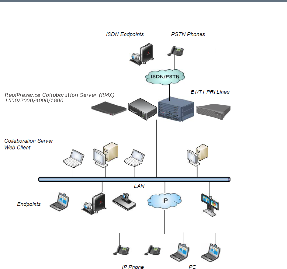
Overview
Polycom®, Inc. 4
Multipoint Video Conferencing using a RealPresence Collaboration Server (RMX) 1500/1800/2000/4000
The RealPresence Collaboration Server system can be controlled via the LAN by the Collaboration Server
Web Client application using Internet Explorer installed on the user’s workstation or the RMX Manager
application. The RMX Manager can control several MCU units. For more information about the RMX
Manager, see RMX Manager Application.
Network Services Guidelines
IP Networks
In Collaboration Server 1500/2000 system management and IP conferencing are performed via a single
LAN port.

Overview
Polycom®, Inc. 5
In Collaboration Server 1800/4000 system management and IP conferencing are performed on separate
LAN ports.
In Collaboration Server 1500/2000/4000 the networks can be separated in Maximum Security
Environments.
ISDN Networks
RealPresence Collaboration Server (RMX) 1500, and Collaboration server 1800-3 with built-in ISDN
module, support one ISDN card with up to 4 E1/T1 PRI lines.
RealPresence Collaboration Server (RMX) 2000/4000 support a maximum of two RTM ISDN cards, each
providing connection for up to either 7 E1 or 9 T1 PRI lines.
On all Collaboration Servers, E1 and T1 connections cannot be used simultaneously.
RealPresence Collaboration Server (RMX) 1800-0 does not support ISDN/PSTN connections.
For more detailed information about Collaboration Server abilities, see Hardware Description in the
RealPresence Collaboration Server (RMX) Hardware Guides.
Card Configuration Modes
The media card installed in the system determines the Card Configuration Mode. The Card Configuration
Mode represents different generations of the media card. Each new generation provides additional
functionality, higher video resolutions and higher resource capacity.
Only one Media Card type can be installed in any Collaboration Server, which sets the Card Configuration
Mode for that Collaboration Server:
●MPMx Card Configuration Mode – Supported from Version 7.0, with MPMx cards installed in the
RealPresence Collaboration Server (RMX) 1500/2000/4000.
●MPMRx Card Configuration Mode – Supported from Version 8.3, with MPMRx cards installed in the
RealPresence Collaboration Server (RMX) 2000/4000.
Viewing the Card Configuration Mode
The Card Configuration Mode is determined according to the installed media card.
The Licensing Mode and the Card Configuration Mode for your MCU can be viewed in the System
Information dialog box (Administration > System Information).
In the example shown here, the Card Configuration Mode is MPMx.
This section is applicable only for MCU with an MPM media card(s), meaning Collaboration Servers
1500/2000/4000 only.
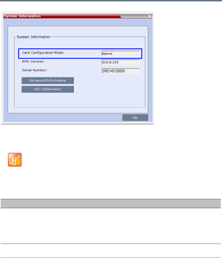
Overview
Polycom®, Inc. 6
Differences Between MPMx and MPMRx Media Cards
The following table lists the Collaboration Server features dependent on the MPMx/MPMRx media cards.
Features Supported with MPMRx Cards
RealPresence Collaboration Server 1800 follows rules similar to Collaboration Servers with MPMRx
media cards, unless otherwise indicated.
Features dissimilar between MPMx/MPMRx Card Configuration Modes
Feature MPMx MPMRx (and RMX 1800)
Video at HD1080p
resolutions
Only asymmetric video HD1080p60
resolution is supported.
All video HD symmetric resolutions
(HD1080p60,30, 15 and
HD720p15/30/60) are supported.
RMX1800-0 only supports HD1080p60
symmetric video when Video Quality is
set as Motion in the conference Profile.
Content at HD1080p
resolutions
Content HD resolution support is limited
to 1080p15.
Content HD resolution support may
reach 1080p60.
H.264 Only base profile. Both base and high profile.

Overview
Polycom®, Inc. 7
The following table lists the Collaboration Server features that are only supported with MPMRx cards
(RealPresence Collaboration Servers 2000 and 4000 only).
General RealPresence Collaboration Server Supported Features
Audio-Video ratio adaptation
slider
Supported. Not supported.
CP conferencing maximum
line rate
CP conferencing line rate is limited to
4Mbps.
Maximum AVC-CP conferencing line
rate: 6Mbps.
RMX1800-0 maximum AVC-CP
conferencing line rate: 4Mbps.
Features Supported with MPMRx Card Configuration Mode
Feature Name Description
HD1080p60 Symmetric HD1080p60 Resolution is symmetric.
HD1080p30/60 Content Content is supported at resolutions of HD1080p30 and HD1080p60 in both
H.264 Base and High Profiles.
An additional check box H.264 High Profile and additional rate values in the
Content Rate drop-down menu have been added to the Video Quality dialog
box.
6Mbps The RealPresence Collaboration Server (RMX) 1800 supports AVC-CP
conferences at a line rates up to and including 6Mbps.
RMX1800-0 maximum AVC-CP conferencing line rate: 4Mbps.
Features Supported in RealPresence Collaboration Server
Feature Name Description
Scalable Video Coding (SVC) Scalable Video Coding (SVC) Conferencing, based on the SVC video protocol
and SAC audio protocol.
SVC Conferencing offers high resolution video conferencing with low
end-to-end latency, improved Error Resiliency and higher system capacities.
w448 Resolution support Improves interoperability with Tandberg MXP 990/3000 endpoints providing
these endpoints the resolution of W448p (768x448 pixels) at 25fps.
HD H.264 Content and H.264
Content for Cascading links
Enables conference participants to receive higher quality Content in both
standard conferences and cascaded conferences.
Site Names Additional controls over the display of site names in the conference Profile.
Interactive Video Forcing Participants in ongoing conferences can be interactively forced to a Video
Window in the conference layout by using Drag and Drop.
Video Preview H.264 High Profile is supported with Video Preview.
Features dissimilar between MPMx/MPMRx Card Configuration Modes
Feature MPMx MPMRx (and RMX 1800)

Overview
Polycom®, Inc. 8
Recording indication A Recording Indication can be displayed to all conference participants
informing them that the conference is being recorded.
Note: Only in non-TIP conferences.
Network Quality Indication A Network Quality Indicator is displayed for each participant in the CP layout
indicating the quality of the participants’ video channels.
Note: Only in non-TIP conferences.
Auto scan and Customized
Polling
A single cell in the conference layout is used to cycle the display of participants
that are not in the conference layout. The order of the cyclic display can be
predefined.
SirenLPR Prevents audio degradation and maintains high audio (CD) quality if packet loss
occurs.
Speaker Change Threshold The option to configure the amount of time a participant must speak
continuously until becoming the speaker.
Integration with Cisco
Telepresence Systems (CTS)
The MCU natively inter-operate with Cisco TelePresence Systems and
Polycom TelePresence and vide conferencing endpoints, ensuring optimum
quality multi-screen, multipoint calls.
Telepresence Mode is not supported by Collaboration Server (RMX) 1800-0.
POCN - Collaboration with
Microsoft and Cisco in the same
environment
The POCN solution, enables Polycom, Microsoft and Cisco users, each within
their own environment, to participate in the same conference running on a
Collaboration Server.
Additional Chinese Font Types Additional Chinese fonts may be selected for several features when using the
Collaboration Server in Chinese.
Support for Microsoft Protocols, algorithms and workflows
RTV Video Protocol Microsoft RTV Video protocol is supported.
RTV B-Frame Support B-frame encoding and decoding are supported to enhance the viewing
experience of Microsoft Lync clients. It provides higher video quality at the
same bit-rate with better scalability on the decoder side.
Conferencing Entities Presence
in Microsoft Office
Communications Server Client or
Lync Server Client
Registration & Presence enables the OCS or LYNC client users to see the
availability status (Available, Busy or Offline) of Meeting Rooms, Entry Queues
and SIP Factories and connect to them directly from the buddy list.
Cascading between
Collaboration Server Meeting
room / Microsoft A/V MCU
Microsoft Lync users can connect a Collaboration Server Meeting Room to a
conference running on the Microsoft A/V MCU.
Microsoft Lync is not supported by Collaboration Server (RMX) 1800-0.
FEC Support Support of Microsoft RTV FEC (Forward Error Correction) that controls and
correct packet loss when receiving and sending video streams using the
Microsoft Lync Server 2010.
ICE Over TCP Enables the automatic usage of the ICE connection through the TCP port
instead of UDP when the UDP port in the firewall is blocked.
Features Supported in RealPresence Collaboration Server
Feature Name Description
Overview
Polycom®, Inc. 9
The RMX Web Client and RMX Manager applications can be installed in an environment that meets the
following requirements:
●Minimum Hardware – Intel® Pentium® III, 1 GHz or higher, 1024 MB RAM, 500 MB free disk space.
●Workstation Operating System – Microsoft® Windows® XP, Windows® 7, and Windows® 8.
●Network Card – 10/100/1000 Mbps.
●Web Browser - Microsoft® Internet Explorer® Version 7, 8, 9, and 10.
●Collaboration Server Web client and RMX Manager are optimized for display at a resolution of 1280
x 800 pixels and a magnification of 100%
The following table lists the environments (Web Browsers and Operating Systems) with which the
Collaboration Server Web Client and RMX Manager applications are supported.
Software Prerequisites and Guidelines
●.Net Framework 3.5 SP1 is required and installed automatically. Internet Explorer must be enabled
to allow running Signed ActiveX.
If ActiveX installation is blocked, see the ActiveX Bypass.
●Collaboration Server Web Client does not support larger Windows text or font sizes. It is recommended to set
the text size to 100% (default) or Normal in the Display settings in Windows Control Panel on all workstations.
Otherwise, some dialog boxes might not appear properly aligned. To change the text size, select Control Panel
> Display. For Windows XP, click the Appearance tab, select Normal for the Font size, and click OK. For
Windows 7, click the Smaller - 100% option, and click OK.
●When installing the Collaboration Server Web Client, Windows Explorer >Internet Options> Security Settings
must be set to Medium or less.
●It is not recommended to run RMX Web Client and Polycom CMAD applications simultaneously on the same
workstation.
Media Over TCP Media is automatically transmitted using TCP when UDP, the default transport
protocol, is not available.
Error Recovery The Collaboration Server can automatically recover from short duration
network errors (5 seconds), enabling calls in Microsoft Lync to continue video
or audio conferences without disconnecting.
Collaboration Server Web Client/RMX Manager Environment Interoperability Table
Web Browser Operating System
Internet Explorer 7 Windows Vista™
Windows 7
Internet Explorer 8 Windows 7
Internet Explorer 9 Windows 7 and Windows 8
Internet Explorer 10* Windows 8
Features Supported in RealPresence Collaboration Server
Feature Name Description
Overview
Polycom®, Inc. 10
●If you have problems getting the Collaboration Server Web Client to work with Windows 8, it is
recommended to run Internet Explorer as an administrator by holding the shift key and right-clicking
on the IE icon, and then select Run as Administrator.
For Windows 7™ Security Settings and Internet Explorer 8 configuration, refer to Windows 7™ Security
Settings and Internet Explorer 8 configuration sections in RealPresence Collaboration Server (RMX)
1500/1800/2000/4000 Getting Started Guide.

Polycom®, Inc. 11
Conferencing Modes Overview
The MCU system offers the following types of conferences (Conferencing Modes), based on the video
protocol and the video display during the conference:
●AVC-based Conferencing - CP Only (Video Transcoding)
●AVC-based Conferencing - Video Switching
●SVC-based Conferencing (Media Relay) - SVC Only
●Mixed AVC and SVC Conferencing - CP and SVC
AVC Conferencing
AVC-based Conferences allow endpoints that support AVC video to connect to these conferences. AVC
(Advanced Video Coding) video refers to the H.264 video protocols used to send and receive video. On the
Collaboration Server system it also includes all the standard video protocols such as H.261, H.263, and
RTV.
All endpoints (including SVC-enabled endpoints) have AVC capabilities and can connect to AVC
conferences running on the MCU. AVC-based endpoints can connect using different signaling protocols and
different video protocols.
Based on the video processing required during the conference, the Collaboration Server offers the
Continuous Presence Conferencing Mode for AVC-based conferencing.
The MCU also offers the Video Switching conferencing Mode.
The Conferencing Mode determines the video display options (full screen or split screen with all participants
viewed simultaneously) and the method in which the video is processed by the MCU (with or without using
the MCU’s video resources).
Continuous Presence (CP) Conferencing
The dynamic Continuous Presence (CP) capability of the Collaboration Server system enables viewing
flexibility by offering multiple viewing options and window layouts for video conferencing. It enables several
participants to be viewed simultaneously and each connected endpoint uses its highest video, audio and
data capabilities up to the maximum line rate set for the conference.
AVC-based endpoints can connect to the conference using any:
●Signaling protocol: H.323, SIP, ISDN/PSTN and RTV line rate, up to a maximum line rate defined for
the conference
●Video Protocol: H.261, H.263, H.264 Base Profile and H.264 High Profile) and at any resolution and
frame rate, provided they meet the minimum requirements set for the conference:
Video Resolutions: from QCIF, CIF and up to 1080p60
Frame rates up to 60fps
In Continuous Presence conferences, the MCU receives the video stream from each endpoint at the video
rate, video resolution and frame rate that it is capable of sending, and it superimposes all the received
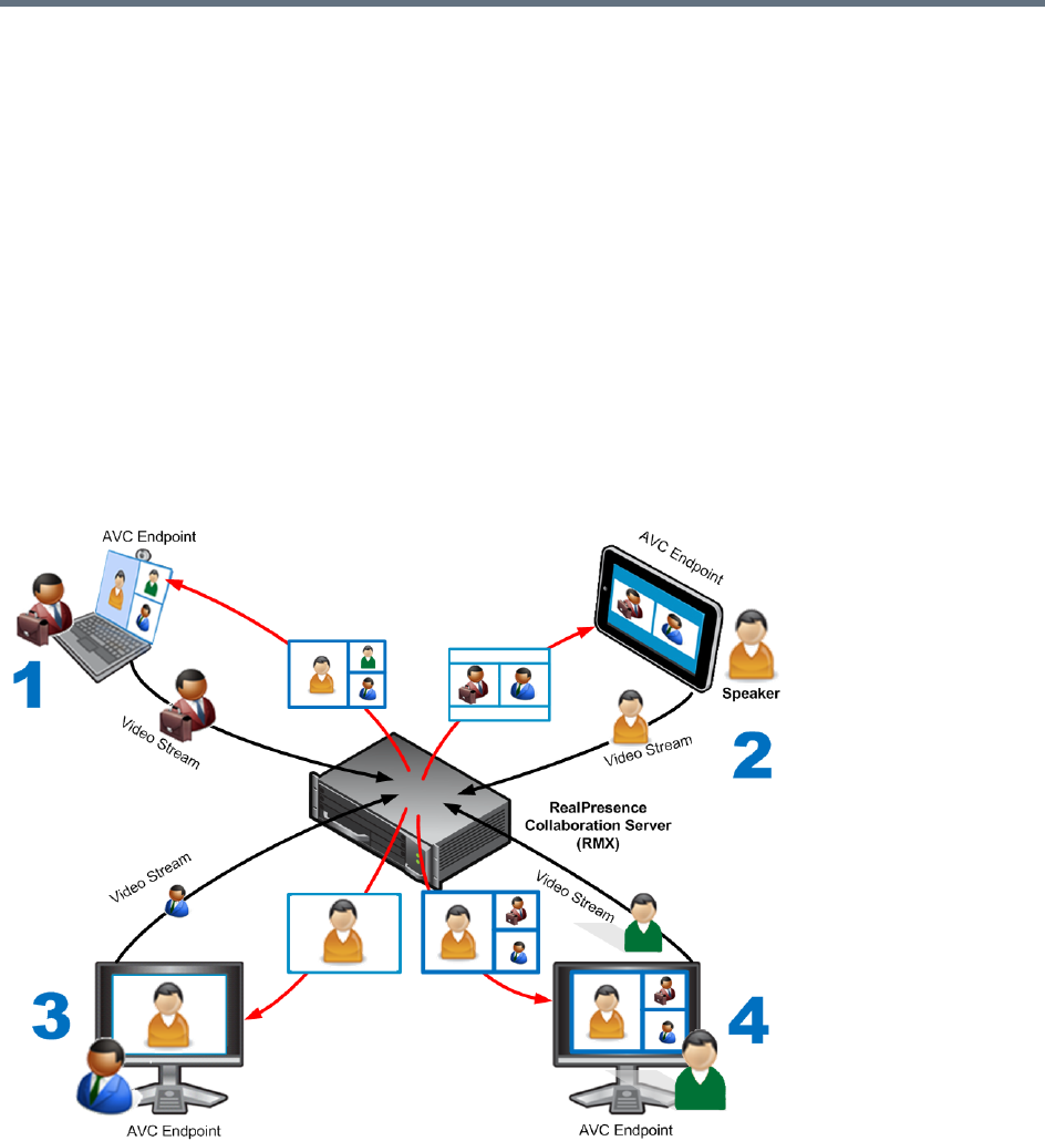
Conferencing Modes Overview
Polycom®, Inc. 12
streams into one video stream that includes the input from the other endpoints arranges in the selected
video layout.
Participants do not see themselves in the video layout. By Default, the speaker is shown in the top left layout
cell in symmetric layouts, in the larger cell in asymmetric layouts, or in full screen. The speaker sees the
previous speakers (their number depends on the number of cells on the speaker’s layout.
The Continuous Presence video session offers layouts to accommodate different numbers of participants
and conference settings including support of the VUI annex to the H.264 protocol for endpoints that transmit
wide video instead of 4CIF resolution. Each participant can select his/her layout for viewing during the
conference, as can be seen in AVC Continuous Presence (CP) video streams and built layouts.
For conferences with more participants than display squares, the RealPresnce Collaboration Server
dynamic video mix capability allows the viewed sites to be modified throughout the conference. The
displayed layout can be changed during an ongoing conference, allowing a participant to view different
screen layouts of the other conference participants. These layout options allow conferences to have greater
flexibility when displaying a large number of participants and maximizes the screen’s effectiveness.
AVC Continuous Presence (CP) video streams and built layouts
Video quality in Continuous Presence conferences is affected by the conference line rate (that determines
the maximum line rate to be used by the connecting endpoints), and the video capabilities of the endpoints
such as the video protocol, video resolution and frame rate. Content sharing is available in all CP
conferences.
This requires extensive processing of the video sent to each participant in the conference. The higher the
video rate and resolution, the more processing power is required.

Conferencing Modes Overview
Polycom®, Inc. 13
By default every conference, Entry Queue and Meeting Room has the ability to declare the maximum CP
resolution as defined for the system. This includes conferences launched by the Collaboration Server Web
Client and conferences started via the API.
CP conferencing is defined in the Conference profile by setting the following main
features:
●Setting the Conferencing Mode to CP only
●Conference Line Rate
●Video Quality – Motion or Sharpness
●Video Layout
Video Protocol Support in CP Conferences
The video protocol selected by the system determines the video compression standard used by the
endpoints. In Continuous Presence conferences, the system selects the best video protocol for each of the
endpoint according to he endpoint’s capabilities.
The following Video protocols are supported in CP conferences:
●H.261 - The legacy video compression algorithm mandatory to all endpoints. It is used by endpoints
that do not support other protocols.
●H.263 - A video compression algorithm that provides a better video quality than H.261. This standard
is not supported by all endpoints.
●H.264 Base Profile - A video compression standard that offers improved video quality, especially at
line rates lower than 384 Kbps.
H.264 High Profile - Allows higher quality video to be transmitted at lower line rates.
●RTV - A video protocol that provides high quality video conferencing capability to Microsoft OCS
(Office Communicator Server) endpoints at resolutions up to HD720p30. (SIP only).
Video Switching (VSW) Conferencing
In Video Switching mode all participants see the same video picture (full screen). The current speaker is
displayed in full screen on all the participants' endpoints, while the speaker sees the previous speaker.
Switching between participants is voice-activated; whenever a participant starts to speak, he or she
becomes the conference speaker and is viewed on all screens. All conference participants must use the
same line rate and video parameters such as video protocol, frame rate, annexes and interlaced video mode
as no video processing is performed. Endpoints that are unable to meet these requirements connect as
Secondary (audio only).
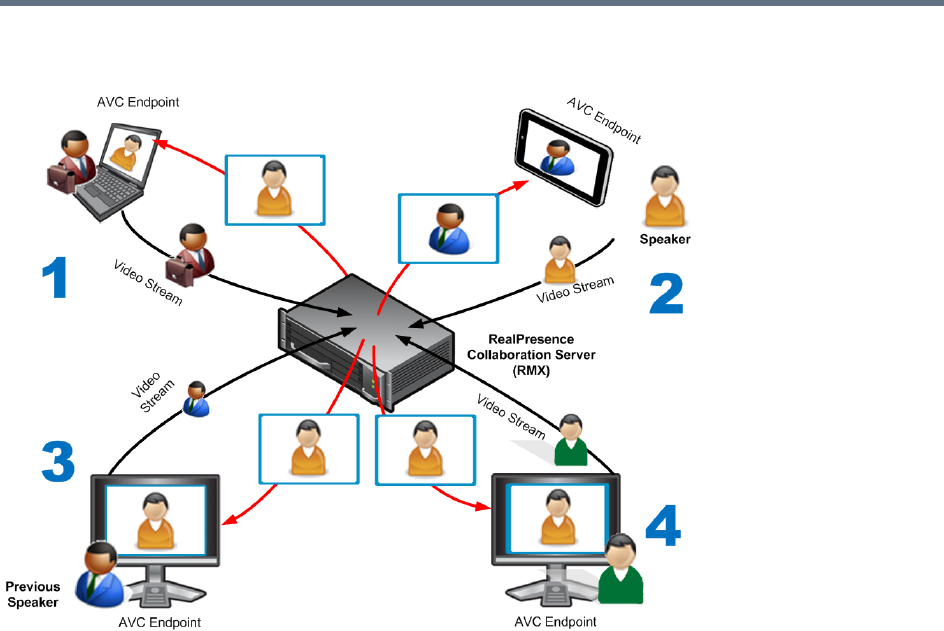
Conferencing Modes Overview
Polycom®, Inc. 14
AVC Video Switching (VSW) video streams and Full Screen Layout
Video Switching (VSW) Conferencing Guidelines
You can run VSW conferences according to the following the guidelines:
●Video Switching conferences can be set to one of the following resolutions, depending on the
capabilities of the endpoints connecting to the conference:
H.264 1080p60 (Symmetrically, at bit rates of up to 6Mbps).
HD1080p60
H.264 1080p30
H.264 720p30
H.264 720p60
H.264 SD 30
H.264 CIF
H.263 CIF
H.261 CIF
●Both H.264 Base and High Profile video protocols are supported.
●Video Switching conferencing mode is unavailable to ISDN participants.
Conferencing Modes Overview
Polycom®, Inc. 15
●Video Switching uses fewer system resources than CP: only one CIF video resource per participant
for any resolution (including HD). The table below lists the resources available to VSW conferences
by line rate and card type.
The following table lists the recommended number of connections at HD1080p resolution for fully
configured and licenced RealPresence Collaboration Server (RMX) systems. For detailed resource
capacity information see the relevant RealPresnce Collaboration Server Hardware Guide.
●The maximum supported video conference size is 180 participants with the MPMx card, or with
Collaboration Server 1800.
●The display aspect ratio is 4x3 or 16x9.
●Site (endpoint) names, skins, message overlay etc. are not supported in Video Switching.
●Video forcing is enabled at the conference and participant levels.
●To connect to a Video Switching conference via Entry Queue, the Profile assigned to the Entry Queue
must be set to Video Switching. It is recommended to use the same profile for both the destination
conference and Entry Queue.
●Telepresence Mode is unavailable in Video Switching conferences.
●In RealPresence Collaboration Server (RMX) 2000/4000 with MPMRx media cards, each participant
connecting to a VSW conference consumes one HD720 port.
VSW Resource Capacity Line Rate
Resource Type
Maximum Possible Resources *
MPMx MPMRx RMX 1800
VSW 2Mbps 80* 65 200
VSW 4Mbps 40* 65 150
VSW 6Mbps 20* 50 100
* Capacity numbers are for maximum capacity card assemblies. These numbers may be lower when LPR
and/or encryption are enabled.
Maximum Number of HD1080p Connections by Line Rate
Line Rate/Participants
RMX 1500
(MPMx) /
RMX 1800
RMX 2000 RMX 4000
MPMx MPMRx MPMx MPMRx
Up to 2Mbps 80 160 130 320 260
4Mbps 40 80 130 160 260
6Mbps 20 40 100 80 200

Conferencing Modes Overview
Polycom®, Inc. 16
●The HD_THRESHOLD_BITRATE flag must be set in the System Configuration. The value of this flag
is the system minimum threshold bit rate for HD resolutions. The line rate selected in the conference
Profile must be the same as or higher than that specified by the HD_THRESHOLD_BITRATE flag.
The HD_THRESHOLD_BITRATE flag line rate value ranges from 384kbps to 4Mbs, default is
768kbps. For more information, see Modifying System Flags.
AVC Basic Conferencing Parameters
The main parameters that define the quality of an AVC-based video conference and its display are:
●Line (Bit) Rate - The transfer rate of video and audio streams. The higher the line (bit) rate, the better
the video quality. The MCU supports the following line rates:
Collaboration Server 1500/2000/4000 with MPMx card - 64kbps to 4096kbps
Collaboration Server 2000/4000 with MPMRx card / Collaboration Server 1800 - 64kbps to 6144kpbs
●Audio Algorithm - The audio compression algorithm determines the quality of the conference audio.
●Video protocol, video format, frame rate, annexes, and interlaced video mode - These
parameters define the quality of the video images. The RealPresnce Collaboration Server will send
video at the best possible resolution supported by endpoints regardless of the resolution received
from the endpoints.
When Sharpness is selected as the Video Quality setting in the Conference Profile, the
RealPresnce Collaboration Server will send 4CIF (H.263) at 15fps instead of CIF (H.264) at 30fps.
H.264 High Profile protocol provides better compression of video images in line rates lower than
384 Kbps and it will be automatically selected for the endpoint if it supports H.264 High Profile. If
the endpoint does not support H.264 High Profile, the RealPresnce Collaboration Server will try
H.264 Base Profile which provides good compression of video images in line rates lower than
384 Kbps (better than H.263 and not as good as H.264 High Profile).
When working with RealPresnce Collaboration Servers at low bit rates (128, 256, or 384Kbps),
HDX endpoints will transmit SD15 resolution instead of 2CIF resolution.
When using a full screen (1x1) conference layout, the RealPresnce Collaboration Server transmits
the same resolution it receives from the endpoint.
●Video resolution:
H.261 CIF/QCIF – Supported in Continuous Presence (CP) conferences at resolutions of 288 x
352 pixels (CIF) and 144 x 176 pixels (QCIF). Both resolutions are supported at frame rates of up
to 30 frames per second.
H.263 4CIF - A high video resolution available to H.263 endpoints that do not support H.264. It is
only supported for conferences in which the video quality is set to sharpness and for lines rates
of 384kbps to 1920kbps.
Standard Definition (SD) - A high quality video protocol which uses the H.264 and H.264 High
Profile video algorithms. It enables compliant endpoints to connect to Continuous Presence
conferences at resolutions of 720 x 576 pixels for PAL systems and 720 x 480 pixels for NTSC
systems.
The HD_THRESHOLD_BIT RATE flag is responsible for negotiation only, It does not guarantee that
the endpoint will open an HD channel or transmit on an opened HD channel.

Conferencing Modes Overview
Polycom®, Inc. 17
High Definition (HD) – HD is an ultra-high quality video resolution that uses the H.264 and H.264
High Profile video algorithms. Depending on the RealPresnce Collaboration Server’s type,
compliant endpoints are able to connect to conferences at the following resolutions:
720p - 1280 x 720 pixels
1080p - 1920 x 1080 pixels
●Lost Packet Recovery (LPR) - LPR creates additional packets that contain recovery information
used to reconstruct packets that are lost during transmission.
Supplemental Conferencing Features
In addition to basic parameters that determine the quality of the video, additional features can be enabled,
adding capabilities to the conference, or enabling special conferencing modes:
●Content Sharing (H.239) – Allows compliant endpoints to transmit and receive two simultaneous
streams of conference data to enable Content sharing. H.239 is also supported in cascading
conferences. Both H.263 and H.264 Content sharing protocols are supported. If all endpoints
connected to the conference have H.264 capability, Content is shared using H.264, otherwise
Content is shared using H.263.
For more information, see Sharing Content During Conferences.
●Video Clarity (CP Conferences only) - Video Clarity applies video enhancing algorithms to
incoming video streams of resolutions up to and including SD.
Video Clarity is not supported by Collaboration Server (RMX) 1800-0.
●Encryption – Used to enhance media security at conference and participant levels.
For more information, see Implementing Media Encryption for Secured Conferencing.
●Conference Recording and Webcasting - The Collaboration Server enables audio and video
recording, streaming, and webcasting of conferences using Polycom RealPresence Capture Servers
or RSS recording systems.
●Lecture Mode (CP Conferences only) – The lecturer is seen by all participants in full screen while
the lecturer views all conference participants in the selected video layout.
For more information, see Lecture Mode.
●Presentation Mode (CP Conferences only) – When the current speaker’s speech exceeds a
predefined time (30 seconds), the conference layout automatically changes to full screen, displaying
the current speaker as the conference lecturer on all the participants’ endpoints. During this time the
speaker’s endpoint displays the previous conference layout. When another participant starts talking,
the Presentation Mode is cancelled and the conference returns to its predefined video layout.
Presentation mode is available with Auto Layout and Same Layout.
If the speaker in a video conference is an Audio Only participant, the Presentation Mode is
disabled for that participant.
Video forcing works in the same way as in Lecture Mode when Presentation Mode is activated,
that is, forcing is only enabled at the conference level, and it only applies to the video layout
viewed by the lecturer.
●Telepresence Mode (CP Conferences only) - Enables the connection of numerous high definition
telepresence rooms and of different models (such as TPX and RPX) into one conference maintaining
the telepresence experience. This mode is enabled by a special license.
Telepresence Mode is not supported by Collaboration Server (RMX) 1800-0.
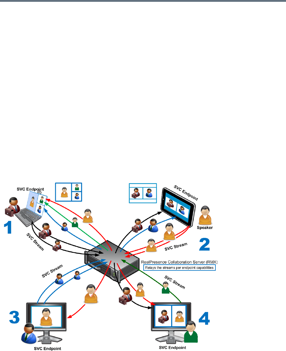
Conferencing Modes Overview
Polycom®, Inc. 18
●TIP Support (CP Conferences only) - TIP is a proprietary protocol created by Cisco for deployment
in Cisco TelePresence systems (CTS). Polycom’s solution is to allow the Collaboration Server to
natively inter-operate with Cisco TelePresence Systems, ensuring optimum quality multi-screen,
multipoint calls.
SVC-based Conferencing
The SVC-Based conferencing mode provides video without transcoding by the MCU, hence requiring less
video resources while providing better error resiliency and lower latency.
Using the SVC video protocol, SVC conferences provide video bit streams at different resolutions, frame
rates and line rates to SVC-enabled endpoints with various display capabilities and layout configurations.
In the SVC-based conference, each SVC-enabled endpoint transmits multiple bit streams, called
simulcasting, to the RealPresence® Collaboration Server. Simulcasting enables each endpoint to transmit
at different resolutions and frame rates such as 720p at 30fps, 15fps, and 7.5fps, 360p at 15fps and 7.5fps,
and 180p at 7.5fps.
The Polycom SVC-enabled endpoints (such as Polycom® RealPresence® Desktop and Polycom®
RealPresence® Mobile) compose the layout according to their layout settings and video capabilities. This
enables the MCU to send or relay the selected video streams to each endpoint without processing the video
streams and sending the composite video layout to the endpoints.
SVC video streams and Layouts
-
The video streams displayed in the conference layout on each endpoint is obtained from the different
streams received from each of the endpoints displayed in the layout. Depending on the size of the video cell

Conferencing Modes Overview
Polycom®, Inc. 19
in the configured layout, the endpoint requests the video stream in the required resolution from the
RealPresence Collaboration Server. The higher the display quality and size, the higher the requested
resolution will be sent to the endpoint. The endpoint creates the displayed layout from the different video
streams it receives.
For instance, an SVC endpoint might want to receive three video streams at different frame rates and
resolutions, and create a conference layout with the received video streams. Each SVC-enabled endpoint
sends encoded SVC bit streams to the MCU to relay to the other SVC-enabled endpoints in the conference.
The endpoints encode the video in multiple resolutions and decodes the multiple video input streams.
For example:
RealPresence mobile client (2) will transmit two resolutions; one that is suited for RealPresence Desktop
client (3) and a second that is suited for two other endpoints: RealPresence Desktop client (4) and (1).
RealPresence Desktop client (1) transmits two resolutions; one that is suited for RealPresence Mobile client
(2) and a second that is suited for RealPresence Desktop client (4).
The MCU determines which of the incoming resolutions to send to each endpoint. It does not perform any
SVC encoding and decoding, or any transcoding of the video streams. The RealPresence Collaboration
Server functions as the multipoint media relay to the endpoints. For voice activated selection of the video
streams, the RealPresence Collaboration Server determines which of the incoming bit streams to send to
each endpoint.
Advantages of SVC Conferencing
SVC increases the scalability of video networks and enables mass desktop video deployments. Some of
the advantages of SVC conferencing are:
●Offers high-resolution video conferencing with low end-to-end latency, improved error resiliency and
higher system capacities.
●Allows the SVC-enabled video endpoints to manage display layouts, supporting multiple line rates,
resolutions and frame rates.
●The RealPresence Collaboration Server functions as a media relay server providing low cost
production benefits. The RealPresence Collaboration Server reduces bandwidth usage by only
selecting the necessary video stream to be sent to the endpoints.
SVC Conferencing Guidelines
You can run SVC-based conferences when following the guidelines listed below.
●SVC conferences are supported only with the following:
SVC Licensing
SIP over UDP signaling
SIP over TLS Signaling
Polycom SVC-enabled endpoints (Polycom® RealPresence® Desktop, Polycom®
RealPresence® Mobile)
Ad Hoc conferencing via Meeting Rooms and ongoing conferences
●SVC Only conferences can run on the same MCU as AVC Only conferences.

Conferencing Modes Overview
Polycom®, Inc. 20
●On RealPresence Collaboration Server (RMX) 2000/4000, all the endpoints participating in a single
SVC Only conference must be connected to the same media card and cannot be handled by different
media cards as the SVC media streams cannot be shared between them.
●End-to-end latency on a local network (same site), is around 200msec to ensure AV sync (also known
as Lip-sync).
●Dial-out is not available in SVC Only conference.
●Dial-in is available as follows:
AVC endpoints (participants) can only connect to an AVC conference or Mixed CP and SVC
conference. When dialing into SVC Only conferences they will be disconnected and the calls fail.
SVC endpoints support both AVC and SVC video protocols:
When dialing into SVC Only conferences, they connect as SVC endpoints.
When dialing into AVC Only conferences, they connect as AVC endpoints. They cannot
connect to an AVC conference using the SVC capabilities.
●SVC endpoints can connect to conferences via Entry Queues, however:
The Entry Queue and Conference Modes must match - both SVC Only or both Mixed.
Both the Entry Queue and the Conference must have the same line rate.
●SVC endpoints cannot be moved between conferences.
●Content is supported in H.264 (AVC).
Only the H.264 Cascade and SVC Optimized option is supported.
LPR and DBA are not supported for SVC content sharing.
●In SVC Only conferences and Mixed CP and SVC conferences, Auto Layout is the default and the
layout display for SVC endpoints is controlled from the endpoint application.
●Site names display on SVC endpoints is controlled from the SVC endpoints.
●When Hot backup is enabled, all the conferences are created on the Slave MCU.
Hot Backup is not supported by Collaboration Server (RMX) 1800-0.
●When Hot Backup is activated and the Slave MCU becomes the Master MCU:
All AVC endpoints will be reconnected to the AVC (CP and VSW) conferences. SVC endpoints
connected to AVC conferences using their AVC capabilities will be reconnected to their AVC
conferences.
SVC endpoints cannot be reconnected to their SVC Only conferences as dial-out is not supported
for SVC endpoints. These endpoints will have to manually reconnect to their SVC conferences.
●Cascading between SVC Only conferences or between AVC and SVC Only conferences is not
supported.
●Gateway sessions are not supported for SVC calls.
●Reservations cannot be scheduled for SVC Only conferences.
●The following functionality and features are not supported during SVC Only conferences:
FECC
Skins. The video cells are displayed on the endpoint’s default background.
IVR functionality
Conference Gathering phase
All DTMF enabled features during the conference
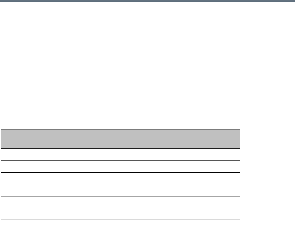
Conferencing Modes Overview
Polycom®, Inc. 21
Manual selection of video layout
Chairperson functionality
Media Encryption
Recording of SVC Only conferences
Text messaging using Message Overlay
MCU Supported Resolutions for SVC Conferencing
The MCU automatically selects the resolution and frame rate according to the conference line rate. The
table below details the maximum resolution and frame rates supported by the MCU for each conference line
rate. The actual video rate, resolution and frame rates displayed on each endpoints is determined by the
endpoint’s capabilities.
SVC Conferencing - Maximum Supported Resolutions per Simulcast Stream
Conference Line Rate
(kbps) Profile
Maximum
Resolution
Max. Frame
Rate (fps)
Audio Rate
(kbps)
2048 - 4096 High Profile 1080p 30fps 48
1472 - 2048 High Profile 720p 30fps 48
1024 - 1472 High Profile 720p 15fps 48
768 - 1024 High Profile 720p 15fps 48
512 - 768 High Profile 360p 30fps 48
256 - 512 Base Profile 180p 15fps 48
192 - 256 Base Profile 180p 30fps 48
128 - 192 Base Profile 180p 15fps 48
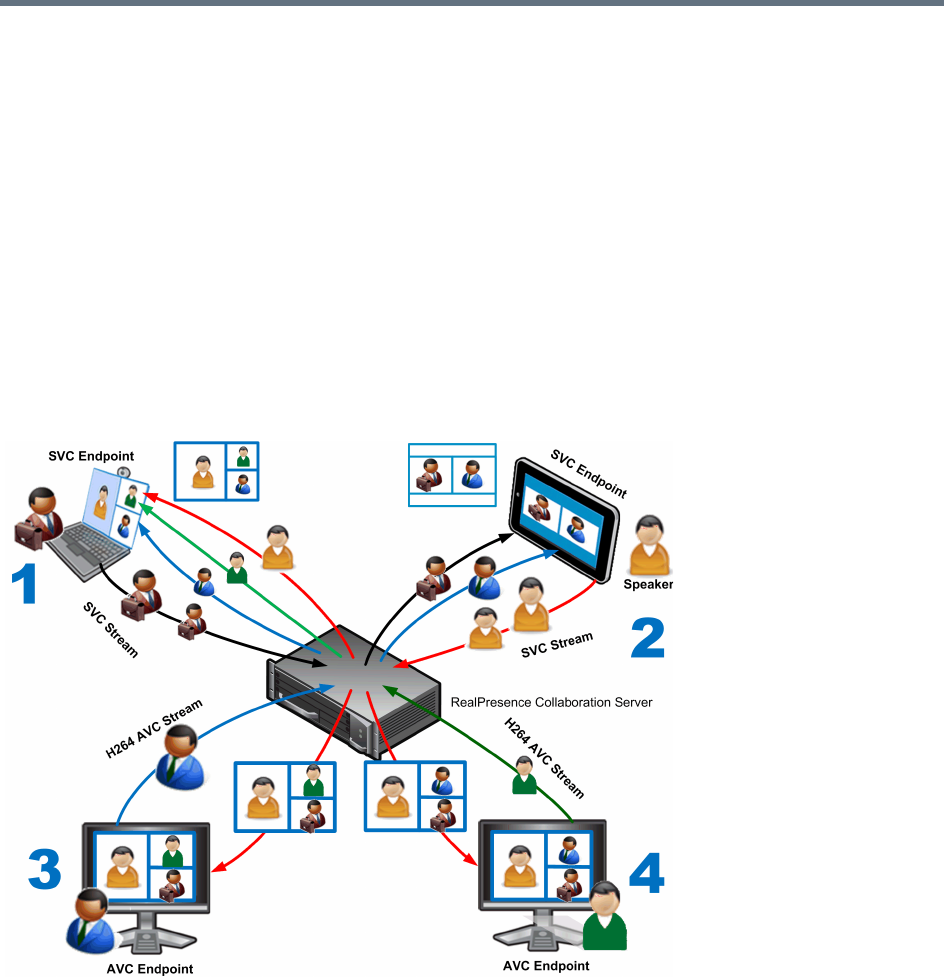
Conferencing Modes Overview
Polycom®, Inc. 22
Mixed CP and SVC Conferencing
In a mixed CP (AVC) and SVC conference, AVC-based endpoints and SVC-enabled endpoints can be
supported in the same conference.
In a mixed CP (AVC) and SVC conference, SVC endpoints transmit multiple resolutions and temporal layers
to the RealPresence Collaboration Server like the SVC-based conferences, while AVC endpoints, for
example, send only one AVC video stream to the Collaboration Server. AVC endpoints can send different
video protocols, such as H.263, and H.264. The Collaboration Server relays SVC-encoded video bit streams
to the SVC-enabled endpoints in the conference according to their request. This enables the video
conference layouts to be automatically assembled by the endpoint. AVC endpoints connected to the
conference send a single AVC video bit stream to the Collaboration Server, which is then transcoded to SVC
video streams. SVC-enabled endpoints receive the AVC converted video bit streams through the
Collaboration Server from the AVC endpoints as a single SVC video bit stream. Alternatively, AVC endpoints
receive a single video bit stream with the defined video conference layout from the Collaboration Server.
The following diagram illustrates an example of a mixed CP and SVC conferencing mode:
In this example, an SVC endpoint (1) receives three video streams at different frame rates and resolutions,
and creates the conference layout with the received video streams. The video bit stream that the SVC
endpoint receives from the AVC endpoint (3) is decoded in the Collaboration Server and then encoded into
an SVC bit stream in the required resolution.
Alternatively, an AVC endpoint (4) sends a single resolution video stream to the Collaboration Server. The
Collaboration Server first decodes the SVC bit streams and AVC bit streams, then the Collaboration Server
composes the video layout for the AVC endpoint and sends a single resolution video stream with the video
layout to the participant. In the displayed example, the Collaboration Server creates different video layouts
for each AVC endpoint.

Conferencing Modes Overview
Polycom®, Inc. 23
MCU Resource Capacities for Mixed CP and SVC Conferences
In a mixed CP and SVC conference, video resources are allocated according to the MCU type and the
translation pools (AVC to SVC and SVC to AVC) used to convert video streams. Translation pools are
dynamically allocated, when the conference becomes a mixed CP and SVC conference; resources are not
released when the conference stops being a mixed CP and SVC conference. The translation pools send
one SVC to AVC stream with a resolution of 360p, two AVC to SVC streams with a resolution of 360p and
180p for AVC HD endpoints, and one video stream with a resolution of 180p for AVC SD endpoints. When
a video stream with a resolution of 360p is not available, a video stream with a resolution of 180p is sent
instead.
Translations between different endpoints can be done without using the highest resolution, thus saving
translation resources. CP video layouts in mixed CP and SVC conferences support the standard resolutions
as in normal CP conferences.
Taking these factors into consideration and the type of MCU deployed in the environment, the resource
capacities for a mixed CP and SVC conference can vary.
For information on resource capacity allocations for the RealPresence Collaboration Server see Resource
Capacities for Full Capacity Collaboration Server per Resolution in Mixed CP and SVC Conferencing.
In a mixed CP and SVC conference, video resources are used according to the amount of both AVC and
SVC participants in the conference and according to the actual type of the conference - mixed CP and SVC
conferences or CP only conferences. The ratio of resources in a mixed conference is one AVC HD (720p30)
video resource to three SVC video resources, meaning for each AVC HD video resource, three SVC video
resources can be allocated.
In this resource capacity allocations example, the mixed CP and SVC conference can allocate a
combination of AVC and SVC ports depending on the endpoints that are defined in the actual conference.
For example, a conference can be defined as a mixed CP and SVC conference but will only allocate
resources as a mixed conference when both AVC and SVC endpoints join the conference. When there are
only one resource type of endpoints participating in the conference, such as AVC or SVC, the resource
allocations are assigned according to the type of endpoint with the system flag
MIX_AVC_SVC_DYNAMIC_ALLOCATION set to TRUE. For instance, a mixed CP and SVC conference
with HD endpoints assigned, can have 60 or 120 ports allocated depending on the server configuration.
When an SVC endpoint joins the conference, the conference becomes an actual mixed conference and the
resource allocations are divided between the AVC and SVC endpoints. The Resource Report will reflect this
by showing an increase in the resource usage.
System Resources are now reported in terms of HD720p30 CP ports. One HD video port equals 3
CIF video ports.
Conferencing Modes Overview
Polycom®, Inc. 24
The following diagram illustrates the amount of AVC to SVC port resources that are used in an actual mixed
CP and SVC conference:

Polycom®, Inc. 25
Using Conference Profiles
Conference Profiles include conference parameters such as Conferencing Mode, conference line rate,
video and content sharing resolutions and settings, video layout, encryption, Lost Packet Recovery (LPR),
etc. Profiles eliminate the need to define these parameters for each new conference created on the MCU.
They are stored on the Collaboration Server and they enable you to define all types of conferences.
The maximum number of Conference Profiles that can be defined is 80.
Conference Profiles are assigned to Conferences, Meeting Rooms, Reservations and Entry Queues. The
same Profile can be assigned to different conferencing entities. When modifying the Profile parameters, the
changes will be applied to all the conferencing entities to which the profile is assigned.
Conference Profile options differ according to the selected Conferencing Mode. Profiles can be defined for
AVC (Advanced Video Codec) CP and VSW, SVC (Scalable Video Codec), or Mixed CP and SVC
conferencing modes.
Conference Profiles can be saved to Conference Templates along with all participant parameters, including
their Personal Layout and Video Forcing settings. It enables administrators and operators to create, save,
schedule and activate identical conferences quickly and easily.
Conferencing Parameters Defined in a Profile
When defining a new video Profile, you select the parameters that determine the video display on the
participant’s endpoint and the quality of the video, according to the selected Conferencing Mode. When
defining a new conference Profile, the system uses default values for the selected conferencing Mode.
In the RealPresence CloudAxis Solution, the Conference Profiles are defined in the RealPresence
DMA system component and should not be defined directly in the RealPresence Collaboration
Server (RMX) 1500/1800/2000/4000 component.

Using Conference Profiles
Polycom®, Inc. 26
Conferencing Capabilities in the Various Conferencing Modes
The following table summarizes the conferencing capabilities and options available in the different
Conferencing Modes.
Conferencing Capabilities in the Different Conferencing Modes
Feature CP Only Mixed CP & SVC SVC Only VSW
Conference Type
Reservations
Operator Conferences
Entry Queues ****
Permanent Conference
Cascading ‡
Conferencing Feature
IVR
Reduced IVR set
for SVC endpoints
Dial Out
Auto Redial
LPR *** ***
Content
Presentation Mode
Lecture Mode
Same Layout
Layout Selection
AVC endpoints only
Layout set to Auto
Layout and defined
on the endpoint
Skins
AVC endpoints only
Encryption

Using Conference Profiles
Polycom®, Inc. 27
Default Profile Settings in CP Conferencing Mode
The Collaboration Server is shipped with a default Conference Profile for CP conferences which allows
users to immediately start standard ongoing CP conferences. These are also the default settings when
creating a new Profile. The default settings are as follows:
Recording
AVC recording only
Site Names
AVC endpoints only
Managed by the
endpoint (not via
MCU)
Message Overlay
AVC endpoints only
* Entry Queue & Destination Conference must have the same profile (i.e. SVC only to SVC only, Mixed CP and SVC
to Mixed CP and SVC)
*** For AVC, the LPR error resiliency is used, however for SVC endpoints, new error resiliency methods are used.
‡ Cascading is not supported on Collaboration Server (RMX) 1800-0.
Default CP Only Conference Profile Settings
Setting Value
Profile Name Factory_Video_Profile
Line Rate 384Kbps
Video Switching Disabled
Operator Conference Disabled
Encryption Disabled
Packet Loss Compensation (LPR
and DBA)
Enabled for CP Conferences
Auto Terminate •After last participant quits - Enabled
•When last participant remains - Disabled
Auto Redialing Disabled
Exclusive Content Mode Disabled
TIP Compatibility Disabled
Enable FECC Enabled
Enabled Gathering Phase Enabled
Conferencing Capabilities in the Different Conferencing Modes
Feature CP Only Mixed CP & SVC SVC Only VSW

Using Conference Profiles
Polycom®, Inc. 28
* Video Clarity, Auto Brightness, and Telepresence Mode are not support by Collaboration Server (RMX)
1800-0.
Display Language English
Video Quality Sharpness
Maximum Resolution Auto
Video Clarity * Enabled
Auto Brightness * Enabled
Content Settings HiResGraphics (High Res Graphics)
Content Protocol H.264 HD
Send Content to legacy endpoints Enabled
Presentation Mode Disabled
Same Layout Disabled
Lecturer View Switching Disabled
Telepresence Mode * Auto
Telepresence Layout Mode Continuous Presence
Auto Scan Interval Disabled (10)
Auto Layout Enabled
Echo Suppression Enabled
Keyboard Noise Suppression Disabled
Audio Clarity Enabled
Mute participants except the lecturer Disabled
Skin Polycom
IVR Name Conference IVR Service
Recording Disabled
Site Names display Disabled
Message Overlay Disabled
Network Services - SIP Registration Disabled
Network Services - Accept Calls Enabled
Default CP Only Conference Profile Settings
Setting Value
Using Conference Profiles
Polycom®, Inc. 29
This Profile is automatically assigned to the following conferencing entities:
Default Profile Settings in SVC Only Conferencing Mode
The Collaboration Server is shipped with a default Conference Profile for SVC Only conferences which
allows users to immediately start standard ongoing SVC Only conferences. These are also the default
settings when creating a new Profile.
The default settings are as follows:
Name ID
Meeting Rooms
Maple_Room 1001
Oak_Room 1002
Juniper_Room 1003
Fig_Room 1004
Entry Queue
Default EQ 1000
Default SVC Only Conference Profile Settings
Setting Value
Profile Name Factory_SVC_Video_Profile
Line Rate 1920Kbps
Video Switching Disabled
Operator Conference Not supported
Encryption Disabled
Packet Loss Compensation (LPR and
DBA)
Not supported
Auto Terminate •After last participant quits - Enabled
•When last participant remains - Disabled
Auto Redialing Not supported
Exclusive Content Mode Disabled
TIP Compatibility Disabled
Enable FECC Disabled
Enabled Gathering Phase Enabled
Display Language English
Video Quality Sharpness
Using Conference Profiles
Polycom®, Inc. 30
* Video Clarity, Auto Brightness, and Telepresence Mode are not support by Collaboration Server (RMX)
1800-0.
Default Profile Settings in a Mixed CP and SVC Conferencing Mode
The Collaboration Server is shipped with a default Conference Profile (CP and SVC) for mixed CP and SVC
conferences which enables users to immediately start a standard ongoing mixed CP and SVC conference.
These are also the default settings when creating a new Profile. (During mixed SVC & CP conferences,
PSTN (Audio Only) calls are supported.) Dial-out is not available in Mixed CP and SVC conferences.
Maximum Resolution Auto
Video Clarity * Enabled
Auto Brightness * Enabled
Content Settings Graphics
Content Protocol H.264 Cascading and SVC Optimized
Presentation Mode Not applicable
Send Content to legacy endpoints Disabled
Same Layout Not applicable
Lecturer View Switching Not applicable
Telepresence Mode * Auto
Telepresence Layout Mode Continuous Presence
Auto Scan Interval Not applicable
Auto Layout Enabled (Only available option)
Echo Suppression Enabled
Keyboard Noise Suppression Disabled
Audio Clarity Enabled
Mute participants except the lecturer Not applicable
IVR Name Conference IVR Service
Message Overlay Disabled
Network Services - SIP Registration Disabled
Network Services - Accept Calls Enabled
Default SVC Only Conference Profile Settings
Setting Value

Using Conference Profiles
Polycom®, Inc. 31
The default settings are as follows
:
Default Mixed CP and SVC Conference Profile Settings
Setting Value
Profile Name Factory_Mix_SVC_CP_Video_Profile
Line Rate 1920Kbps
Video Switching Disabled
Operator Conference Disabled
Encryption Enabled
Packet Loss Compensation (LPR
and DBA)
Enabled for AVC participants only
Auto Terminate •After last participant quits - Enabled
•When last participant remains - Disabled
Auto Redialing Disabled
Font for text over video Enabled for AVC participants only
Exclusive Content Mode Disabled
TIP Compatibility Disabled
Enable FECC Enabled
Enabled Gathering Phase Enabled
Display Language English
Video Quality Sharpness
Maximum Resolution Auto
Video Clarity * Disabled
Auto Brightness * Disabled
Content Settings Graphics
Content Protocol H.264 Cascade and SVC Optimized (only)
Presentation Mode Disabled
Send Content to legacy endpoints Disabled
Same Layout Enabled
Lecturer View Switching Disabled
Telepresence Mode * Off
Telepresence Layout Mode Continuous Presence
Auto Scan Interval Disabled
Using Conference Profiles
Polycom®, Inc. 32
* Video Clarity, Auto Brightness, and Telepresence Mode are not support by Collaboration Server (RMX)
1800-0.
This Profile is automatically assigned to the following conferencing entities:
Viewing the List of Conference Profiles
Existing Conference Profiles are listed in the Conference Profiles list pane.
Auto Layout Enabled
Echo Suppression Enabled for AVC participants only
Keyboard Noise Suppression Enabled for AVC participants only
Audio Clarity Enabled for AVC participants only
Mute participants except the lecturer Disabled
Skin Classic (for AVC participants)
IVR Name Conference IVR Service
Recording Enabled
Site Names display Enabled for AVC participants only
Message Overlay Disabled
Network Services - SIP Registration Disabled
Network Services - Accept Calls Enabled
Network quality indication Enabled for AVC participants only
Name ID
Meeting Rooms
Maple_Room 1001
Oak_Room 1002
Juniper_Room 1003
Fig_Room 1004
Entry Queue
Default EQ 1000
Default Mixed CP and SVC Conference Profile Settings
Setting Value
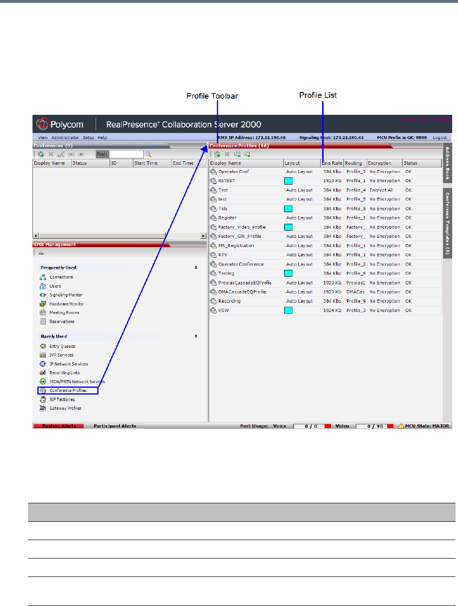
Using Conference Profiles
Polycom®, Inc. 33
To list Conference Profiles:
1In the RMX Management pane, expand the Rarely Used list.
2In the RMX Management pane, click the Conference Profiles button.
The Conference Profiles are displayed in the Conference Profiles list pane.
The number of the currently defined conference profiles appears in the title of the list pane.
The following Conference Profile properties are displayed in the List pane:
Conference Profiles Pane Columns
Field Description
Name The name of the Conference Profile.
Layout Displays either Auto Layout or an icon of the layout selected for the profile.
Line Rate The maximum bit rate in kbps at which endpoints can connect to the conference.
Routing Name Displays the Routing Name defined by the user or automatically generated by the
system.
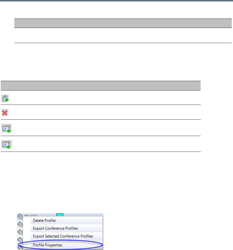
Using Conference Profiles
Polycom®, Inc. 34
Profiles Toolbar
The Profile toolbar provides quick access to the Profile functions:
Modifying an Existing Profile
You can modify any of the Profile’s parameters but you cannot rename the Profile.
To modify the Profile properties:
1In the Conference Profiles List, double-click the Profile icon, or right-click the Profile icon, and
select Profile Properties.
The Profile Properties - General dialog box opens.
2Modify the required Profile parameter(s).
3Click OK.
Encryption Displays if media encryption is enabled for the Profile. For more information see
Packet Loss Compensation - LPR and DBA.
Profile Toolbar buttons
Button Button Name Description
New Profile To create a new Profile.
Delete Profile To delete a Profile, click the Profile name and then click this
button.
Import Profile To import Conference Profiles from another MCU in your
environment.
Export Profile To export Conference Profiles to a single XML file that can be
used to import the Conference Profiles on multiple MCUs.
Conference Profiles Pane Columns
Field Description

Using Conference Profiles
Polycom®, Inc. 35
Deleting a Conference Profile
You can delete profiles from the Profiles list.
To delete a Conference Profile:
1List the profiles that are currently defined in the system. For details, see Viewing the List of
Conference Profiles.
2In the Conference Profiles list, select the Conference Profile you want to delete.
3Click the Delete Profile () button.
or
Right-click the Conference Profile you wish to delete, and select Delete Profile from the menu.
4In the confirmation dialog box, click OK.
The Conference Profile is deleted.
Defining New Profiles
Profiles are the basis for the definition of all ongoing conferences, Reservations, Meeting Rooms, Entry
Queues, and Conference Templates and they contain only conference properties.
Profiles can be defined for the following Conferencing Modes: AVC (Advanced Video Codec) CP and VSW,
SVC (Scalable Video Codec) or Mixed CP and SVC. The Profile tabs and options change according to the
selected Conferencing Mode and only supported options are available for selection. Unsupported options
are disabled (grayed out).
CP Conferencing Mode also offers a special functional conference - Operator Conference.
To facilitate the definition process of a new Profile, the system displays default values for each parameter
so you need only to modify the required settings.
To define a new Profile:
1In the RMX Management pane, expand the Rarely Used list.
2In the RMX Management pane, click Conference Profiles.
3In the Conference Profiles pane, click the New Profile button.
The New Profile – General dialog box opens.
4In the Display Name field, enter the profile name.
A Conference Profile cannot be deleted if it is being used by Meeting Rooms, Reservations, Entry
Queues, and SIP Factories. A Profile that is assigned to only one ongoing conference and no other
conferencing entity can be deleted.
In the RealPresence CloudAxis Solution, the Conference Profiles are defined in the RealPresence
DMA system component and should not be defined directly in the RealPresence Collaboration
Server (RMX) 1500/1800/2000/4000 component.

Using Conference Profiles
Polycom®, Inc. 36
5Select the appropriate Conferencing Mode: CP, VSW, SVC Only or CP and SVC.
The New Profile tabs and options change according to the selected Conferencing Mode and only
supported options are available for selection.
6Define the profile parameters as described in:
Defining AVC CP Conferencing Profiles
Defining an AVC Video Switching Conference Profile
Defining SVC Conference Profiles
Defining Mixed CP and SVC Conferencing Profiles
Exporting and Importing Conference Profiles
Conference Profiles can be exported from one MCU and imported to multiple MCUs in your environment,
enabling you to copy the Conference Profiles definitions to other systems. This can save configuration time
and ensures that identical settings are used for conferences running on different MCUs. This is especially
important in environments using cascading conferences that are running on different MCUs.
Guidelines for Exporting and Importing Conference Profiles
●Only Collaboration Server system administrators can export and import Conference Profiles.
Operators are only allowed to export Conference Profiles.
●You can select a single, multiple, or all Conference Profiles to be exported.
●Conference Templates and their related Conference Profiles can be exported and imported
simultaneously using the Conference Templates export and import function. For more information,
see Exporting and Importing Conference Templates.
Exporting Conference Profiles
Conference Profiles are exported to a single XML file that can be used to import the Conference Profiles on
multiple MCUs. Using the Export Conference Profile feature, you can export all or selected Conference
Profiles from an MCU.
Exporting All Conference Profiles from an MCU
To export all Conference Profiles from an MCU:
1List the profiles that are currently defined in the system. For details, see Viewing the List of
Conference Profiles.
2In the Conference Profiles List toolbar, click the Export Conference Profiles button, or
right-click anywhere in the Conference Profiles pane, and then click Export Conference Profiles.
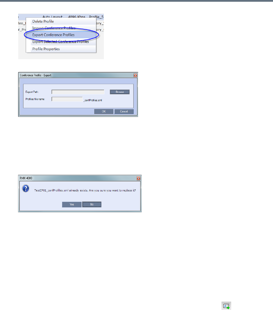
Using Conference Profiles
Polycom®, Inc. 37
The Conference Profile - Export dialog box is displayed.
3In the Export Path field, click Browse to navigate to the location of the desired path where you want
to save the exported file.
4In the Profiles file name field, type the file name prefix. The file name suffix (_confProfiles.xml) is
predefined by the system. For example, if you type Profiles01, the exported file name is defined
as Profiles01_confProfiles.xml.
5Click OK to export the Conference Profiles to a file.
If the export file with the same file name already exists, a prompt is displayed.
6Click Yes to replace the exported file, or click No to cancel the export operation and return to the
Conference Profiles list. You can modify the export file name and restart the export operation.
Exporting Selected Conference Profiles
You can select a single Conference Profile or multiple Conference Profiles and export them to a file to be
imported to other MCUs in your environment.
To export selected Conference Profiles:
1List the Profile that are currently defined in the system. For details, see Viewing the List of
Conference Profiles.
2In the Conference Profiles pane, select the profiles you want to export.
3In the Conference Profiles List toolbar, click the Export Conference Profiles button, or
right-click the selected Conference Profiles, and then click Export Selected Conference Profiles.
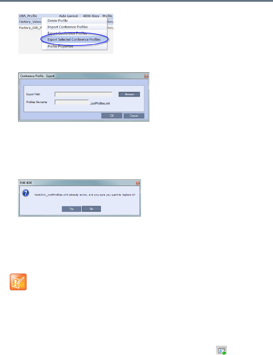
Using Conference Profiles
Polycom®, Inc. 38
The Conference Profile - Export dialog box is displayed.
4In the Export Path field, click Browse to navigate to the location of the desired path where you want
to save the exported file.
5In the Profiles file name field, type the file name prefix. The file name suffix (_confProfiles.xml) is
predefined by the system. For example, if you type Profiles01, the exported file name is defined
as Profiles01_confProfiles.xml.
6Click OK to export the Conference Profiles to a file.
If the export file with the same file name already exists, a prompt is displayed.
7Click Yes to replace the exported file, or click No to cancel the export operation and return to the
Conference Profiles list. You can modify the export file name, and restart the export operation.
Importing Conference Profiles
If your environment includes two or more MCUs, import previously exported Conference Profiles to your
MCU to save configuration time and ensure that all MCUs use the same conferencing parameters.
Conference Profiles are not imported when a Conference Profile with that name already exists or if an IVR
Service which is assigned to any of the imported profiles does not exist in the MCU.
To import Conference Profiles:
1Display the Conference Profiles List. For details, see Viewing the List of Conference Profiles.
2In the Conference Profiles List toolbar, click the Import Conference Profiles button, or
right-click the Conference Profiles pane, and then click Import Conference Profiles.
Conference Profiles are not imported when a Conference Profile with that name already exists or if
an IVR Service which is assigned to any of the imported Profile does not exist in the MCU.
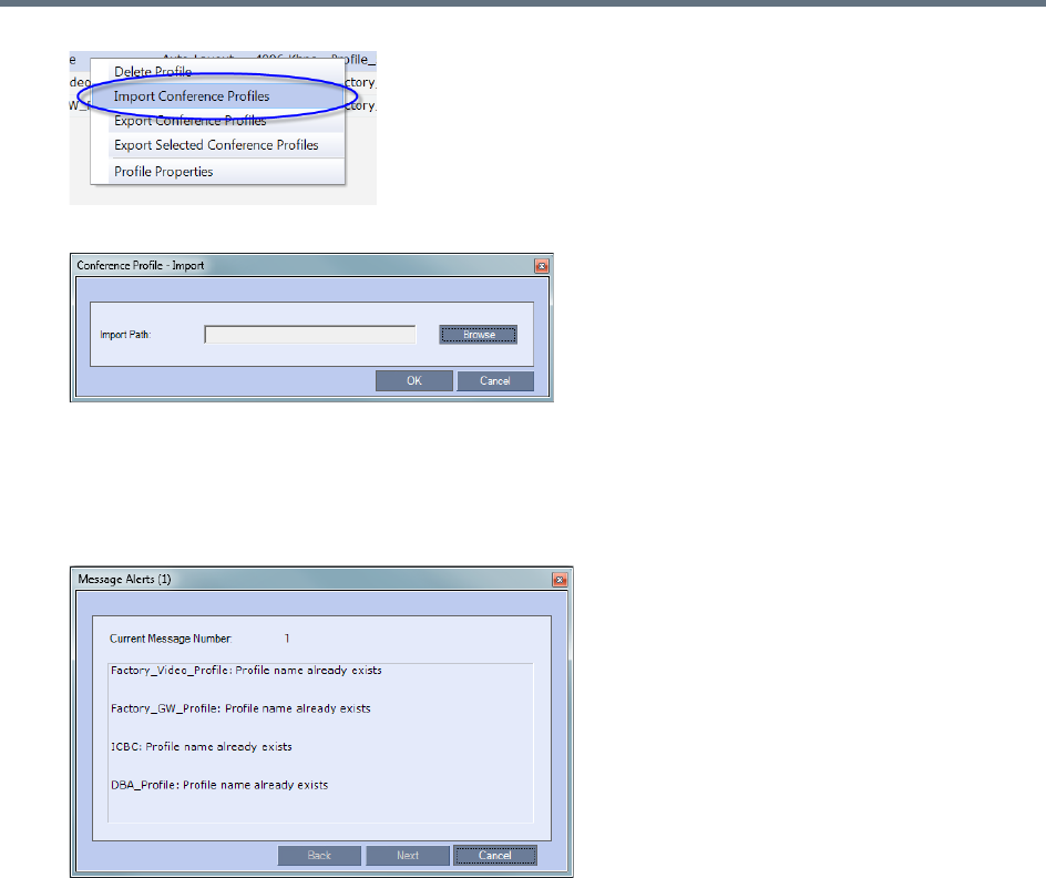
Using Conference Profiles
Polycom®, Inc. 39
The Conference Profile - Import dialog box is displayed.
3In the Import Path field, click Browse to navigate to the path and file name of the exported
Conference Profiles you want to import.
4Click OK to import the Conference Profiles.
When Conference Profiles cannot be imported, a Message Alert window is displayed with the
profiles that were not imported.
Conference Profiles that are not problematic are imported.
5Click Cancel to exit the Message Alerts window.
The imported Conference Profiles appear in the Conference Profiles list.

Polycom®, Inc. 40
Defining AVC-Based Conference Profiles
AVC-based Conference Profile options differ according to the selected Conferencing Mode CP and VSW.
To facilitate the definition process of a new Profile, the system displays default values for each parameter
so you need only to modify the required settings.
Defining AVC CP Conferencing Profiles
When defining a new Profile, you select the parameters that determine the video display on the participant’s
endpoint, the quality of the video, content sharing parameters, whether the conference will be recorded,
encryption, Telepresence mode and other conferencing parameters.
The following parameters are defined:
●New AVC CP Profile - General Parameters
●New AVC CP Profile - Advanced Parameters
●New AVC CP Profile - Gathering Settings Parameters
●New AVC CP Profile - Video Quality Parameters
●New AVC CP Profile - Video Settings Parameters
●New AVC CP Profile - Audio Settings Parameters
●New AVC CP Profile - IVR Parameters
●New AVC CP Profile - Recording Parameters
●New AVC CP Profile - Site Names Parameters
●New AVC CP Profile - Message Overlay Parameters
●New AVC CP Profile - Network Services Parameters
●New AVC CP Profile - Layout Indications Parameters
To define a new CP Profile:
1In the RMX Management pane, click Conference Profiles.
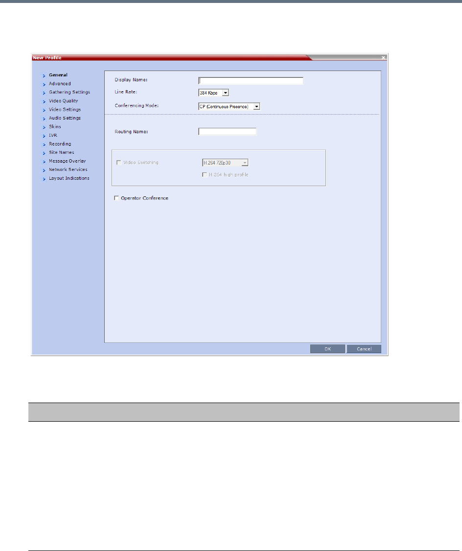
Defining AVC-Based Conference Profiles
Polycom®, Inc. 41
2In the Conference Profiles pane, click the New Profile button.
The New Profile – General dialog box opens.
3Define the Profile name and, if required, the Profile - General parameters:
New AVC CP Profile - General Parameters
Field/Option Description
Display Name Enter a unique Profile name, as follows:
•
English text uses ASCII encoding and can contain the most characters (length
varies according to the field).
•European and Latin text length is approximately half the length of the maximum.
•Asian text length is approximately one third of the length of the maximum.
It is recommended to use a name that indicates the Profile type, such as CP or
Operator conference.
Notes:
•This is the only parameter that must be defined when creating a new profile.
•This field is displayed in all tabs.

Defining AVC-Based Conference Profiles
Polycom®, Inc. 42
Line Rate Select the conference bit rate. The line rate
represents the combined video, audio
and Content rate
.
The default setting is 384 Kbps.
Notes:
•This field is displayed in all tabs.
•The maximum line rate at which ISDN endpoints can connect to a conference is
768 kbps.
Downspeeding is not supported. As a result, ISDN calls will consume
bandwidth resources according to the Line Rate specified in the conference
Profile. For example, if the conference Line Rate is 512kbps, ISDN calls
connecting at lower line rates (256kbps) will still consume the bandwidth
resources of 512kbps calls. As a result, if bandwidth resources are fully
consumed, ISDN calls may be rejected before media card resources are
exhausted.
•The Collaboration Server supports AVC-CP conferences at line rates of up to
6Mbps:
For Dial-in calls only.
For use with HD1080p30/60 and HD720p60 resolutions.
To prevent excessive bandwidth usage and resource consumption, the system
will ignore a Line Rate of 6Mbps, substituting line rates appropriate to the
Maximum Resolution defined.
For MPMRx and RMX1800:
Up to 1Mbps for SD30, CIF60 and below
Up to 4Mbps for SD60, HD720p30
Up to 6Mbps for HD720p60, HD1080p30, HD1080p60
For MPMx:
Up to 2Mbps for SD30, CIF60 and below
Up to 4Mbps for SD60, HD720p30 and above
(RMX1800-0 maximum AVC-CP conferencing line rate: 4Mbps.)
•If ‘Maximum Resolution’ is specified in ‘Video Quality Parameters’, the line rate
might be modified automatically according to table ‘Maximum negotiated line
rate for resolutions’.
•If ‘Maximum Resolution’ is specified in ‘Video Quality Parameters’, the line rate
might be modified automatically according to the Maximum Negotiated Line Rate
for Resolutions table.
Conferencing Mode Select the required Conferencing Mode. The selection affects the available tabs
and their fields.
Notes:
•This field is displayed in all tabs.
•If the selected Line Rate is higher than 4Mbps, and Conferencing Mode is
modified to SVC Only or CP and SVC, the line rate is dropped to match
SVC-enabled conferencing rates.
New AVC CP Profile - General Parameters
Field/Option Description

Defining AVC-Based Conference Profiles
Polycom®, Inc. 43
Routing Name Enter the Profile name using ASCII characters set.
The Routing Name can be defined by the user or automatically generated by the
system if no Routing Name is entered as follows:
•If an all ASCII text is entered in Display Name, it is used also as the Routing
Name.
•If any combination of Unicode and ASCII text (or full Unicode text) is entered in
Display Name, the ID (such as Conference ID) is used as the Routing Name.
Video Switching Disabled. Applicable for VSW conferencing. For more information, see Defining an
AVC Video Switching Conference Profile.
H.264 High Profile Disabled. Applicable for VSW conferencing. For more information, see H.264 High
Profile Support in Video Switching Conferences.
Operator Conference
(CP Only)
Select this option to define the profile of an Operator conference.
An Operator conference can only be a Continuous Presence conference, therefore
when selected, the Video Switching option is disabled and cleared.
When defining an Operator Conference, the Send Content to Legacy Endpoints
option in the Video Quality tab is cleared and disabled.
For more information, see Operator Assistance & Participant Move.
New AVC CP Profile - General Parameters
Field/Option Description
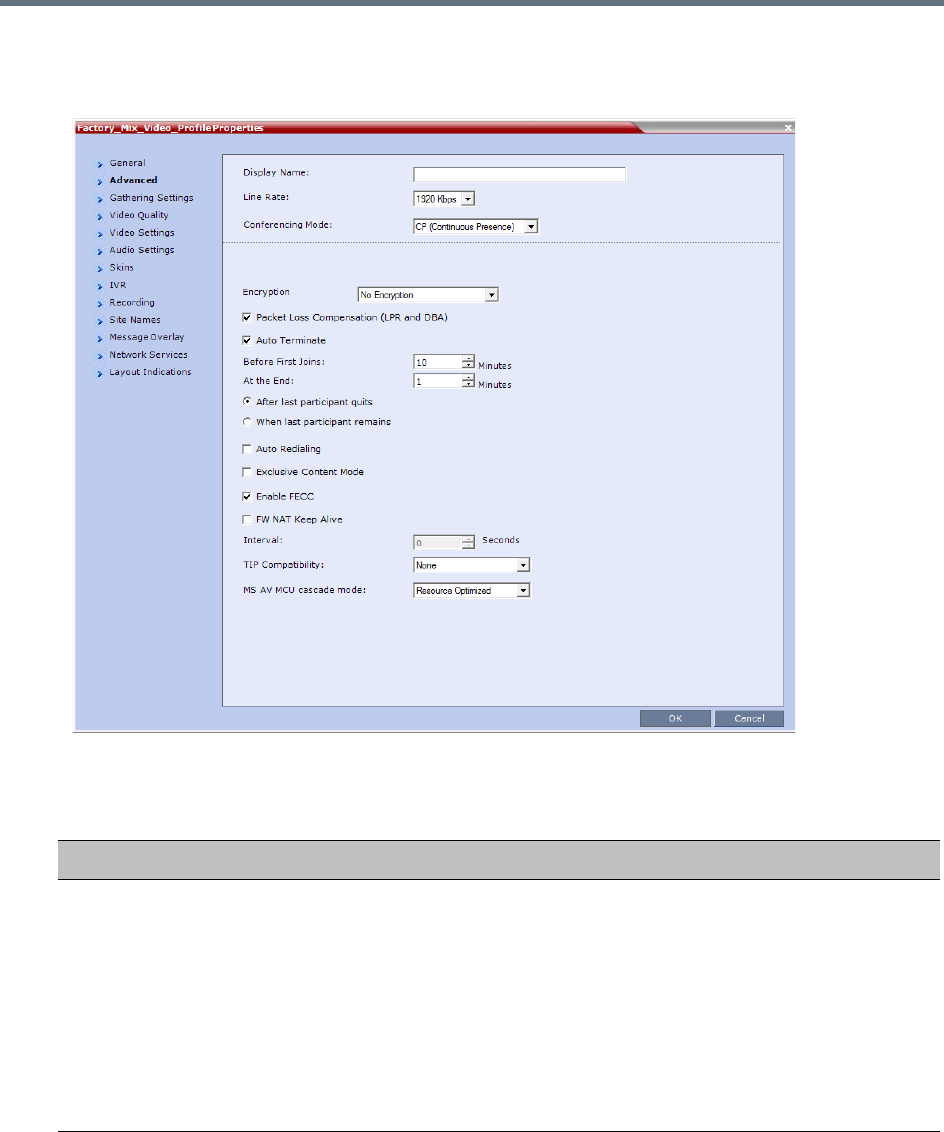
Defining AVC-Based Conference Profiles
Polycom®, Inc. 44
4Click the Advanced tab.
The New Profile – Advanced dialog box opens.
5Define the following parameters:
New AVC CP Profile - Advanced Parameters
Field/Option Description
Encryption Select the Encryption option for the conference:
•Encrypt All - Encryption is enabled for the conference and all conference
participants must be encrypted.
•No Encryption - Encryption is disabled for the conference.
• Encrypt when Possible - Enables the negotiation between the MCU and the
endpoints and let the MCU connect the participants according to their
capabilities, where encryption is the preferred setting. For connection
guidelines see Mixing Encrypted and Non-encrypted Endpoints in one
Conference.
For more information, see Packet Loss Compensation - LPR and DBA.

Defining AVC-Based Conference Profiles
Polycom®, Inc. 45
LPR When selected (default for CP conferences), Lost Packet Recovery creates
additional packets that contain recovery information used to reconstruct packets
that are lost during transmission.
The LPR check box is automatically cleared if Video Switching is selected as
the Conferencing Mode, but can be selected if required.
For more information, see Packet Loss Compensation - LPR and DBA.
Auto Terminate When selected (default), the conference automatically ends when the
termination conditions are met:
• Before First Joins — No participant has connected to a conference during
the n minutes after it started. Default idle time is 10 minutes.
• At the End - After Last Quits — All the participants disconnected from the
conference, and the conference is idle (empty) for the predefined time period.
Default idle time is 1 minute.
• At the End - When Last Participant Remains — Only one participant is
connected to the conference for the predefined time period (excluding the
recording link which is not considered a participant when this option is
selected). This option should be selected when defining a Profile that will be
used for Gateway Calls, and wishing to ensure the call is automatically
terminated when only one participant is connected. Default idle time is 1
minute.
Note: The selection of this option is automatically cleared and disabled when
the Operator Conference option is selected. The Operator conference cannot
automatically end unless it is terminated by the Collaboration Server User.
Auto Redialing The Auto Redialing option instructs the Collaboration Server to automatically
redial H.323 and SIP participants that have been abnormally disconnected from
the conference.
•Auto Redialing is disabled by default.
•Auto Redialing can be enabled or disabled during an ongoing conference
using the Conference Properties – Advanced dialog box.
•The Collaboration Server will not redial an endpoint that has been
disconnected from the conference by the participant.
•The Collaboration Server will not redial an endpoint that has been
disconnected or deleted from the conference by an operator or administrator.
Exclusive Content Mode Select this option to limit the Content broadcasting to one participant, preventing
other participants from interrupting the Content broadcasting while it is active.
New AVC CP Profile - Advanced Parameters
Field/Option Description

Defining AVC-Based Conference Profiles
Polycom®, Inc. 46
TIP Compatibility Select the TIP Compatibility mode when implementing a Collaboration Server
and Cisco Telepresence Systems (CTS) Integration solution. The TIP
Compatibility mode affects the user video and content experience.
The following TIP Compatibility modes are available:
•None
•Prefer TIP
From Version 8.1.1, Polycom endpoints can also connect to Entry Queues,
Meeting Rooms and conferences using the TIP protocol.
The connection of the Polycom endpoints with TIP protocol to a TIP Compatible
Entry Queues, Meeting Rooms and conferences using the TIP protocol is
enabled when the Polycom endpoints are registered to the CUCM and the
Prefer TIP option is selected in the conference Profile.
When the Prefer TIP option is selected, conferencing entities can include
endpoints connected using all protocols, including TIP and SIP protocols.
When Prefer TIP is selected, Gathering Settings, content settings, Message
Overlay, Site Names and Network Indication(s) cannot be enabled.
Note: If an option other than None is selected in this field, the Gathering
Settings options are disabled.
For more information, see .
Enable FECC This option is enabled by default, allowing participants in the conference to
control the zoom and PAN of other endpoints in the conference via the FECC
channel. Clear this check box to disable this option for all conference
participants.
FW NAT Keep Alive The MCU can be configured to send a FW NAT Keep Alive message at specific
Intervals for the RTP, UDP and BFCP channels.
For more information see FW (Firewall) NAT Keep Alive.
Interval If needed, modify the NAT Keep Alive Interval field within the range of 1 - 86400
seconds. For more information see FW (Firewall) NAT Keep Alive.
MS AV MCU Cascade
Mode
This enables you to set Cascade Mode as either Resource Optimized or Video
Optimized.
• Resource Optimized
System resource usage is optimized by allowing high resolution connections
only at high line rates and may result in lower video resolutions for some line
rates. This option allows you to save MCU resources and increase the
number of participant connections.
• Video Quality Optimized
Video is optimized through higher resolution connections at lower line rates
increasing the resource usage at lower line rates. This may decrease the
number of participant connections.
For more information, see H.264 Base Profile and High Profile Comparison.
New AVC CP Profile - Advanced Parameters
Field/Option Description
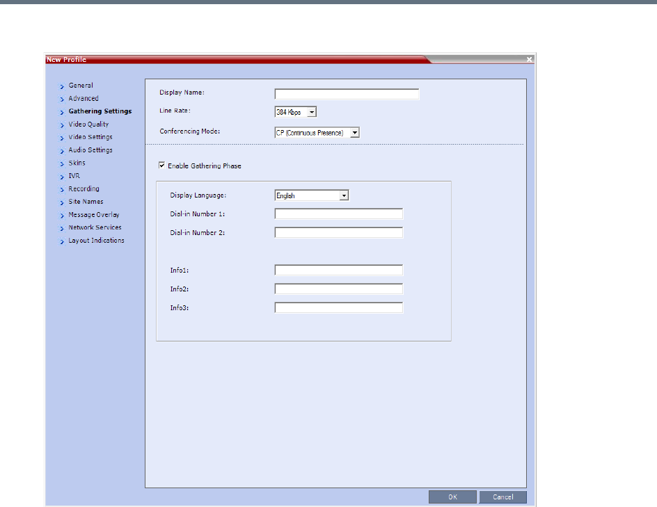
Defining AVC-Based Conference Profiles
Polycom®, Inc. 47
6 For CP Conferences only: Click the Gathering Settings tab.
7 Optional. Define the following fields if the conference is not launched by the Polycom Conferencing
Add-in for Microsoft Outlook:
Defining AVC-Based Conference Profiles
Polycom®, Inc. 48
•If the conference is launched by the Polycom Conferencing Add-in for Microsoft Outlook the field
information is received from the meeting invitation and existing field value are overridden. For
more information see Polycom Conferencing for Microsoft Outlook®.
•The Gathering option is disabled in gateway calls.
•Gathering is not supported in Cascading Conferences.
•Cascading is not supported by Collaboration Server (RMX) 18000-0.
New AVC CP Profile - Gathering Settings Parameters
Field Description
Display Name This field is defined when the Profile is created. For more information see the
Defining New Profiles.
Enable Gathering Select this check box to enable the Gathering Phase feature.
Default: Selected.
Displayed Language Select the Gathering Phase slide language:
Gathering Phase slide field headings are displayed in the language selected.
The Gathering Phase slide can be in a different language to the Collaboration
Server Web Client.
Default: English
Note: When working with the Polycom Conferencing Add-in for Microsoft Outlook,
the language selected should match the language selected for the conference in the
Polycom Conferencing Add-in for Microsoft Outlook to ensure that the Gathering
Phase slide displays correctly.
Dial-in Number 1 Enter the ISDN or PSTN number(s) to call to connect to the conference.
Note: The numbers entered must be verified as the actual Access Numbers.
Dial-in Number 2
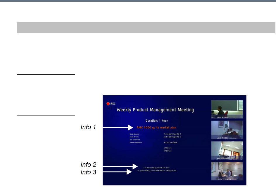
Defining AVC-Based Conference Profiles
Polycom®, Inc. 49
For more information see Auto Scan and Customized Polling in Video Layout.
Info 1 Optionally, enter any additional information to be displayed during the Gathering
Phase.
These fields are not limited in the Collaboration Server Web Client but only 96
characters can be displayed in the Gathering Slide on a 16:9 monitor.
If the Gathering slide is displayed on a 4:3 endpoint: the slide is cropped on both
sides:
•The left most characters of the information fields are not displayed.
•The live video is cropped on the right side of the display.
Info 2
Info 3
New AVC CP Profile - Gathering Settings Parameters
Field Description
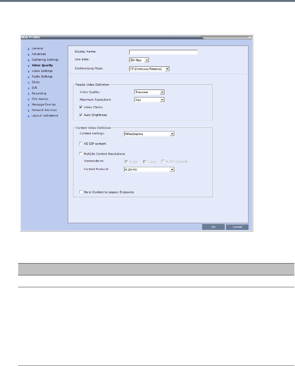
Defining AVC-Based Conference Profiles
Polycom®, Inc. 50
8Click the Video Quality tab.
The New Profile – Video Quality dialog box opens.
9Define the following parameters:
New AVC CP Profile - Video Quality Parameters
Field/Option Description
People Video Definition
Video Quality Sharpness is the only supported content format that supports higher video
resolutions.
Depending on the amount of movement contained in the conference video, select
either:
•Motion – For a higher frame rate without increased resolution. When selected,
Video Clarity is disabled.
•Sharpness – For higher video resolution and requires more system resources.
Note: When Sharpness is selected as the Video Quality setting in the conference
Profile, the Collaboration Server will send 4CIF (H.263) at 15fps instead of CIF
(H.264) at 30fps.

Defining AVC-Based Conference Profiles
Polycom®, Inc. 51
Maximum Resolution This setting overrides the Maximum Resolution setting of the Resolution
Configuration dialog box.
The administrator can select one of the following Maximum Resolution options:
• Auto (default) - The Maximum Resolution remains as selected in the
Resolution Configuration dialog box.
•CIF
•SD
• HD720
• HD1080
Maximum Resolution settings can be monitored in the Profile Properties - Video
Quality and Participant Properties - Advanced dialog boxes.
Notes:
•The Resolution field in the New Participant - Advanced dialog box allows
Maximum Resolution to be further limited per participant endpoint.
•The Maximum Resolution settings for conferences and participants cannot be
changed during an ongoing conference.
Video Clarity™ When enabled (default), video enhancing algorithms is applied to incoming video
streams of resolutions up to and including SD. Clearer images with sharper edges
and higher contrast are sent back to all endpoints at the highest possible resolution
supported by each endpoint.
All layouts, including 1x1, are supported.
Notes:
Video Clarity is enabled only when Video Quality is set to Sharpness (default
setting) and is disabled when Video Quality is set to Motion.
Video Clarity is not supported by Collaboration Server (RMX) 1800-0.
Auto Brightness Auto Brightness detects and automatically adjusts the brightness of video windows
that are dimmer than other video windows in the conference layout.
•Auto Brightness only increases brightness and does not darken video windows.
•Auto Brightness is selected by default.
•Auto Brightness cannot be selected and deselected during an ongoing
conference.
•When Auto Brightness is enabled, color changes may be observed in
computer-based VGA Content sent by HDX endpoints through the People video
channel.
Default: On
Auto Brightness is not supported by Collaboration Server (RMX) 1800-0.
New AVC CP Profile - Video Quality Parameters
Field/Option Description
Defining AVC-Based Conference Profiles
Polycom®, Inc. 52
Content Video Definition
Content Settings Select the transmission mode for the Content channel:
•Graphics — Basic mode, intended for normal graphics
• Hi-res Graphics — Higher bit rate intended for high resolution graphic display
• Live Video — Content channel displays live video
• Customized Content Rate — Manual definition of the Conference Content
Rate, mainly for cascading conferences.
Selection of a higher bit rate for the Content results in a lower bit rate for the people
channel.
For a detailed description of each of these options, see Content Sharing
Parameters in Content Highest Common (Content Video Switching) Mode.
AS SIP Content AS-SIP is an implementation of SIP that utilizes SIP’s built in security features.
When selected, content is shared using the Multiple Resolutions mode and is not
supported in any other Content sharing mode.
For more information, see Enabling AS-SIP Content.
Multiple Content
Resolutions
Click this check box to enable the Multiple Content Resolutions mode, in which
content is shared in multiple streams, one for each video protocol: H.263 and
H.264. This allows endpoints with different protocols to connect and disconnect
without having to restart Content sharing in the middle of a conference. For more
information, see Multiple Content Resolutions.
When enabled, the H.264 is always selected and can not be deselected.
Note: If Multiple Content Resolutions is selected in a Cascading environment, the
Content Protocol must be set to H.264 Cascade Optimized, and the Transcode
to field must be set (checked) to H.264 Cascade.
Optional. Select additional protocols:
•H.263 - if the conference will include H.263-capable endpoints that do not support
H.264 protocol for content sharing.
• H.264 Cascade - if the conference will include cascading links that should use a
fixed video format for content sharing.
Optional. If H.264 Cascade is selected, select the desired Content Resolution.
New AVC CP Profile - Video Quality Parameters
Field/Option Description

Defining AVC-Based Conference Profiles
Polycom®, Inc. 53
Content Protocol Select the Content Protocol to be used for content sharing in Highest Common
Content Sharing Mode.
•H.263
Content is shared using the H.263 protocol.
Use this option when most of the endpoints support H.263 and some endpoints
support H.264.
• H.263 & H.264 Auto Selection
When selected, content is shared using H.263 if a mix of H.263-supporting and
H.264-supporting endpoints are connected, or H.264 if all connected endpoints
have H.264 capability.
• H.264 Cascade Optimized
All Content is shared using the H.264 content protocol and is optimized for use
in cascaded conferences.
• H.264 HD (default)
Ensures high quality Content when most endpoints support H.264 and HD
resolutions.
Note: When Multiple Content Resolutions is selected, the Content Protocol field
is hidden.
For more information, see Content Protocols and Defining Content Sharing
Parameters for a Conference
H.264 High Profile The H.264 High Profile check box is un-checked by default and is displayed next to
the Content Protocol drop-down menu if all the following conditions are met:
•The MCU is a RealPresence Collaboration Server 1800, or 2000/4000 containing
MPMRx cards.
•Conferencing mode is VSW (Video Switching).
•Multiple Resolutions (Content Transcoding) is not selected.
•The selected Content Protocol is H.264 Cascade Optimized.
If H.264 HD, H.264 Cascade Optimized is selected, the Content Resolution is
set according to the line rate.
•TIP Compatibility (in the Profile - Advanced dialog box) is selected as None.
Content Resolution Select the Content Resolution and frame rate according to the selected Content
Sharing Mode (Highest common Content or Multiple Resolution Contents) and the
video protocol. For more information, see Defining Content Sharing Parameters for
a Conference.
Content Rate The Content Rate drop-down menu is displayed next to the Content Resolution
drop-down menu when:
• H.264 Cascade Optimized is the selected Content Protocol
and
• CustomizedContentRate is the selected Content Setting.
The Content Rate is dependent on the MCU type (RealPresence Collaboration
Server with MPMRx or RealPresence Collaboration Server 1800) and can be up to
66% of the conference line rate. In MCUs with MPMx cards the Content Rate is
limited to 2048 kbps, while when used with the RealPresence Collaboration Server
1800 the Content Rate is limited to 4096 kbps.
New AVC CP Profile - Video Quality Parameters
Field/Option Description
Defining AVC-Based Conference Profiles
Polycom®, Inc. 54
Send Content to
Legacy Endpoints
(CP / mixed CP and
SVC)
When enabled (default) Content can be sent to H.323/SIP/ISDN endpoints that do
not support H.239 Content (legacy endpoints) over the video (people) channel. For
more information see Sending Content to Legacy Endpoints.
Notes:
•When enabled, an additional HD video resource is allocated to the conference.
•This option is valid when sending Content as a separate stream is enabled by
setting the System Flag ENABLE_H239 to YES.
•Select this option when Avaya IP Softphone will be connecting to the conference.
•In Video Switching Conferencing Mode the Send Content to Legacy Endpoints
option is disabled.
•If the Same Layout option is selected, the Send Content to Legacy Endpoints
selection is cleared and disabled.
•Once an endpoint is categorized as Legacy, it will not be able to restore its
content to the Content channel and will receive content only in the video channel.
H.264 High Profile
(Not displayed with
MPMx media cards.)
Displayed only when the Conferencing Mode is VSW (Video Switching) and H.263
& H.264 Auto Selection or H.264 HD is the selected in Content Protocol, Base
Profile or High Profile will be auto selected based on the endpoint’s capability (up to
HD1080p60).
New AVC CP Profile - Video Quality Parameters
Field/Option Description
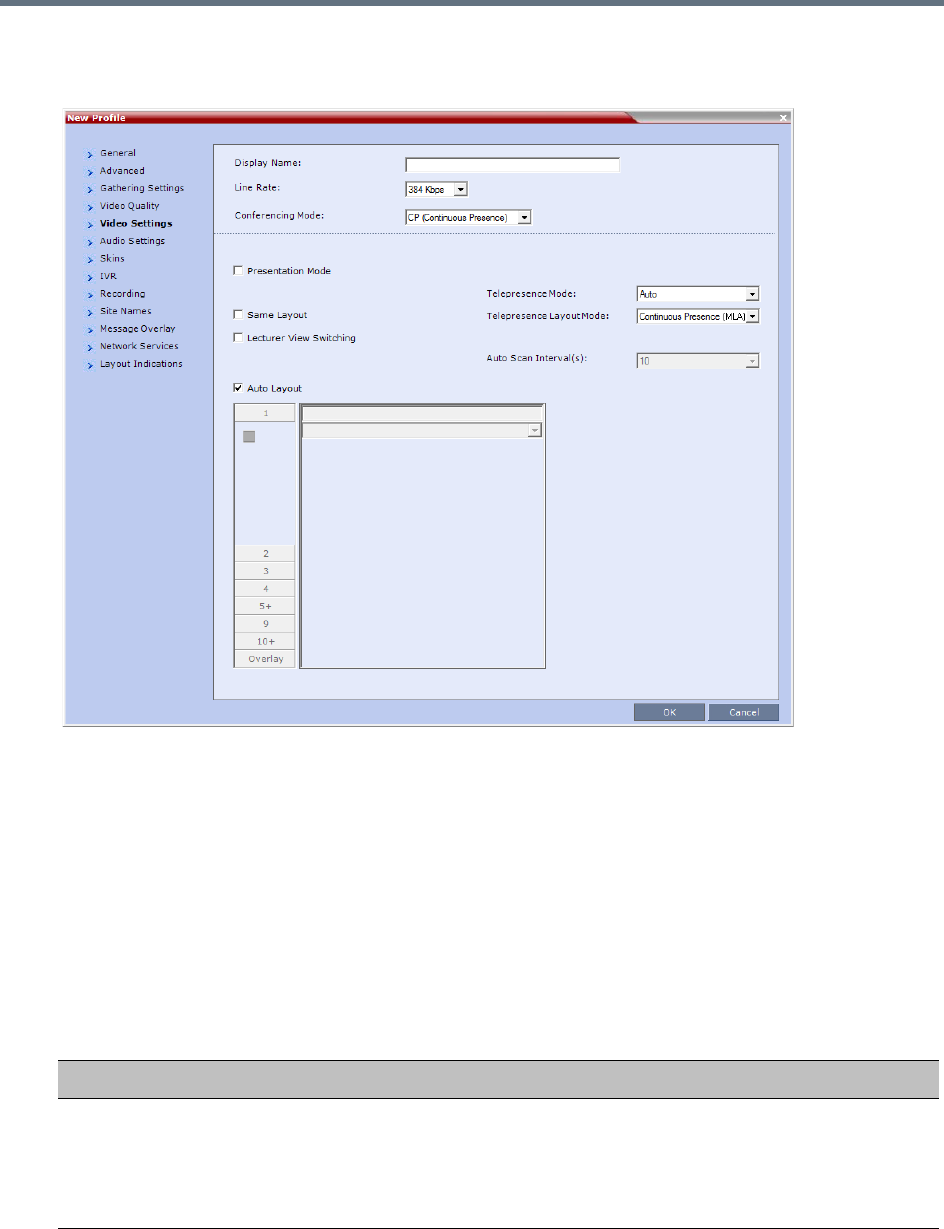
Defining AVC-Based Conference Profiles
Polycom®, Inc. 55
10 Click the Video Settings tab.
The New Profile - Video Settings dialog box opens.
In AVC-based CP and Mixed CP and SVC conferences, while the conference is running, you can
change the video layout and select one of the video layouts supported by the MCU.
Video Layout selection can be done in two levels:
Conference Level – Applies to all conference participants. All participants have the same video
layout.
Participant Level – The participant’s video layout is changed. The video layout of all other
conference participants is unaffected.
Participant level video layout selection overrides conference level video layout settings. Participants
cannot change their Personal Layouts when Lecturer Mode is enabled.
11 Define the video display mode and layout using the following parameters:
New AVC CP Profile - Video Settings Parameters
Field/Option Description
Presentation Mode
(CP only)
Select this option to activate the Presentation Mode.
In this mode, when the current speaker speaks for a predefined time (30 seconds),
the conference changes to Lecture Mode. When another participant starts talking,
the Presentation Mode is cancelled and the conference returns to the previous
video layout.

Defining AVC-Based Conference Profiles
Polycom®, Inc. 56
Same Layout
(CP only)
Select this option to force the selected layout on all participants in a conference.
Displays the same video stream to all participants and personal selection of the
video layout is disabled. In addition, if participants are forced to a video layout
window, they can see themselves.
Lecture View
Switching
Select this option to enable automatic switching of participants on the Lecturer’s
screen when Lecture Mode is enabled for the conference.
The automatic switching is enabled when the number of participants exceeds the
number of video windows displayed on the Lecturer’s screen.
Note: Lecture Mode is enabled in the Conference Properties – Participants tab.
For more information, see Lecture Mode.
Telepresence Mode
(CP only)
Select the Telepresence Mode from the drop-down menu:
•Off - Normal conference video is sent by the Collaboration Server.
•Auto (Default) - If any ITP (Immersive Telepresence) endpoints are detected,
ITP features are applied to the conference video for all participants.
When Auto is selected, the ITP features are dynamic. If all ITP endpoints
disconnect from the conference, normal conference video is resumed for all
participants. ITP features are resumed for all participants should an ITP
endpoint re-connects to the conference.
• On - ITP features are applied to the conference video for all participants
regardless of whether there are ITP endpoints connected or not.
Notes:
•This field is enabled only if the Collaboration Server system is licensed for
Telepresence Mode.
•Telepresence Mode is unavailable in Video Switching conferences.
•Telepresence Mode is not supported by Collaboration Server (RMX) 1800-0.
Telepresence Layout
Mode
(CP only)
The Telepresence Layout Mode drop-down menu enables VNOC operators and
Polycom Multi Layout Applications to retrieve Telepresence Layout Mode
information from the Collaboration Server.
The following modes can be selected:
•Manual
• Continuous Presence (MLA) - Room Continuous Presence (Default)
• Speaker Priority For more information see Speaker Priority in CP Video
Layouts.
• Room Switch - Voice Activated Room Switching. For more information see
Room Switch Telepresence Layouts.
Note: This field is enabled only if the Collaboration Server system is licensed for
Telepresence Mode.
Auto Scan Interval(s)
(CP only)
Select the time interval, 5 - 300 seconds, that Auto Scan uses to cycle the display
of participants that are not in the conference layout in the selected cell.
Auto Scan is often used in conjunction with Customized Polling which allows the
cyclic display to be set to a predefined order for a predefined time period.
New AVC CP Profile - Video Settings Parameters
Field/Option Description
Defining AVC-Based Conference Profiles
Polycom®, Inc. 57
Auto Layout
(CP only)
When selected (default), the system automatically selects the conference layout
based on the number of participants currently connected to the conference. When a
new video participant connects or disconnects, the conference layout automatically
changes to reflect the new number of video participants.
For more information, see Auto Layout – Default Layouts in CP Conferences.
Clear this selection to manually select a layout for the conference.
The default Auto Layout settings can be customized by modifying default Auto
Layout system flags in the System Configuration file. For more information see
Auto Layout Configuration.
Note: In some cases, the default layout automatically selected for the conference
contains more cells than the number of connected participants, resulting in an
empty cell. For example, if the number of connected participants is 4, the default
layout is 2x2, but as only 3 participants are displayed in the layout (the participants
do not see themselves), one cell is empty.
New AVC CP Profile - Video Settings Parameters
Field/Option Description
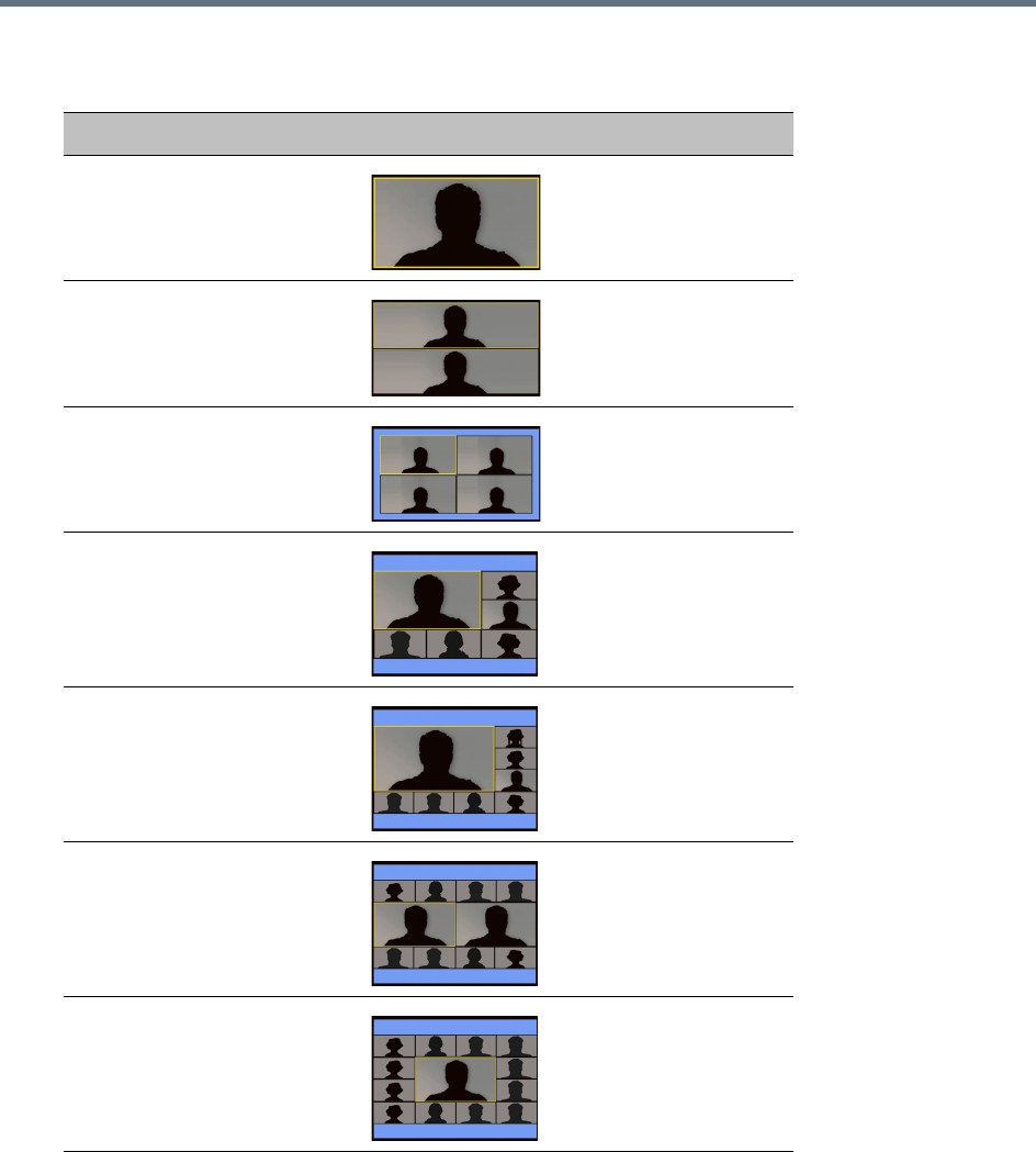
Defining AVC-Based Conference Profiles
Polycom®, Inc. 58
In layout 2+8, the two central windows display the last two speakers in the conference: the current
speaker and the “previous” speaker. To minimize the changes in the layout, when a new speaker is
identified the “previous” speaker is replaced by the new speaker while the current speaker remains
in his/her window.
Auto Layout – Default Layouts in CP Conferences
Number of Video Participants Auto Layout Default Settings
0–2
3
4–5
6–7
8-10
11
12+
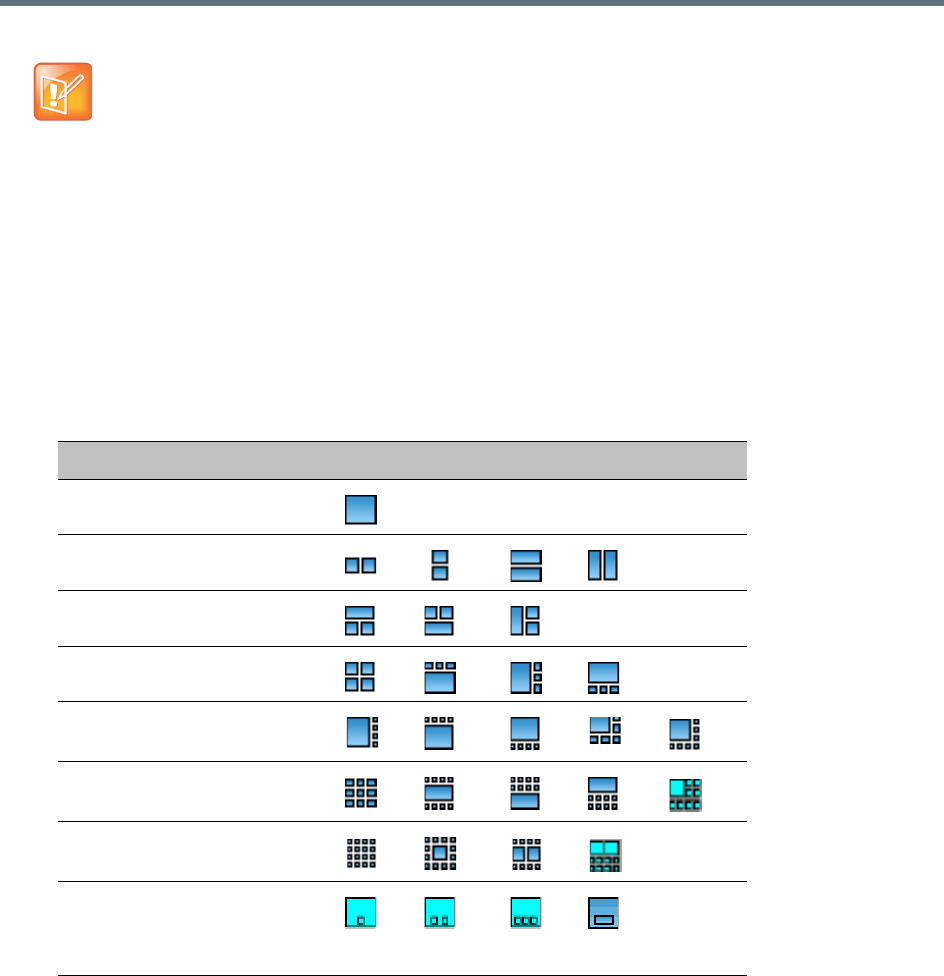
Defining AVC-Based Conference Profiles
Polycom®, Inc. 59
12 Optional. To select the Video Layout for the conference, deselect the Auto Layout, and click the
required number of windows from the layouts bar and then select the windows array. The selected
layout is displayed in the Video Layout pane.
•The Collaboration Server supports the VUI addition to the H.264 protocol for endpoints that
transmit wide video (16:9) in standard 4SIF resolution.
•When there is a change of speaker in a Continuous Presence conference, the transition is set by
default to fade in the current speaker while fading out the previous speaker.
To make this transition visually pleasant, fading in the current speaker while fading out the
previous speaker is done over a period of 500 milliseconds.
The Fade In/Out feature can be disabled by adding FADE_IN_FADE_OUT as a new flag to the
System Configuration, and setting its value to NO.
For more information about System Flags, see Modifying System Flags.
Video Layout Options
Number of Video Windows Available Video Layouts
1
2
3
4
5+
9
10+
Overlay
For more information see Overlay Layouts.
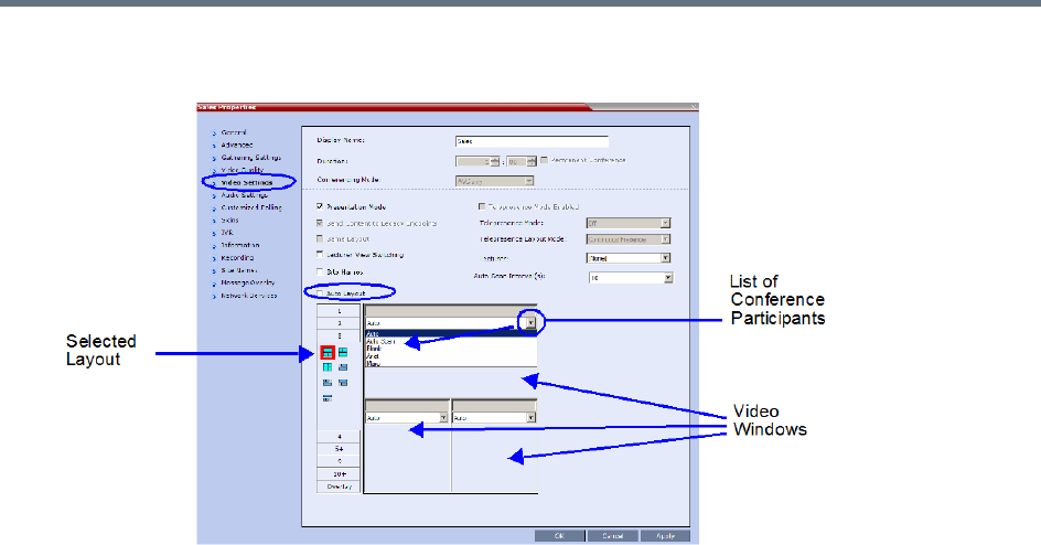
Defining AVC-Based Conference Profiles
Polycom®, Inc. 60
13 Optional. To video force a participant in a window, select the participant’s name from the drop-down
list of conference participants.
When a participant is forced to a layout window, switching between participants is suspended for that
window and only the assigned participant is viewed. Video Forcing works on Conference Level or
Participant Level:
Conference Level – When forcing a participant to a window, all conference participants will see
that participant in the selected window.
Participant Level – When forcing a participant to a window, only the participant’s video layout
display is affected. All other participants see the conference layout.
Video Forcing Guidelines:
A participant cannot appear in two or more windows at the same time.
Participant level video forcing overrides conference level video forcing.
In Same Layout mode, participant can view him/herself in a layout window.
When different size video windows are used in video layouts such as 1+2, 1+3, 1+4, etc., a
participant can only be forced, in Personal Layout, to a video window of the same size as that
selected for him/her in Conference Layout.
When changing the Video Layout at the conference level, the video forcing settings are not
applied to a new layout, and switching between participants is audio-activated. The video forcing
setting is saved and applied the next time that layout is selected.
Windows that are not assigned any participant display the current speaker and last speakers, but
appear at random.
Video Forcing doesn’t change the conference profile.
Video Forcing can be implemented through Media Sources Tab when adding a new Conference or a
new Meeting Room.
For information about preventing the MCU from reassigning cells in a forced layout that were
assigned to endpoints that have disconnected through a system flag named
PRESERVE_PARTY_CELL_ON_FORCE_LAYOUT, see System Configuration Flags.
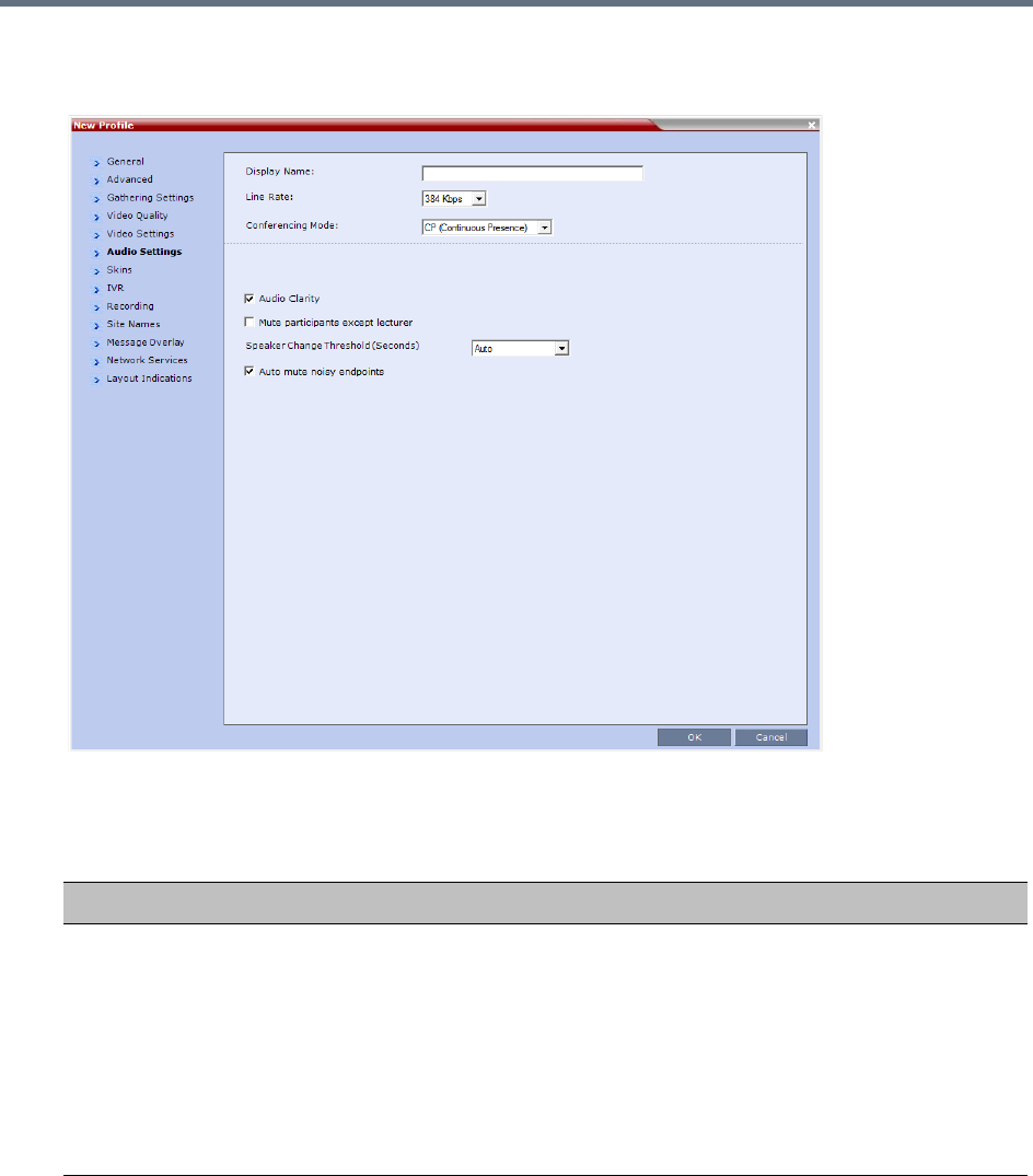
Defining AVC-Based Conference Profiles
Polycom®, Inc. 61
14 Click the Audio Settings tab.
The New Profile - Audio Settings dialog box opens.
15 Define the following parameters:
New AVC CP Profile - Audio Settings Parameters
Field/Option Description
Audio Clarity When selected, improves received audio from participants connected via low audio
bandwidth connections, by stretching the fidelity of the narrowband telephone
connection to improve call clarity.
•The enhancement is applied to the following low bandwidth (8kHz) audio
algorithms: G.729a and G.711
•Audio Clarity is supported with MPMx and MPMRx cards only (RealPresence
Collaboration Server (RMX) 1500/2000/4000).
•Audio Clarity is selected by default.
•Audio Clarity cannot be selected and deselected during an ongoing conference.

Defining AVC-Based Conference Profiles
Polycom®, Inc. 62
Mute participant
except lecturer
When the Mute Participants Except Lecturer option is enabled, the audio of all
participants in the conference except for the lecturer can be automatically muted
upon connection to the conference. This prevents other conference participants
from accidentally interrupting the lecture, or from a noisy participant affecting the
audio quality of the entire conference. Muted participants cannot unmute
themselves unless they are unmuted from the Collaboration Server Web
Client/RMX Manager.
You can enable or disable this option during the ongoing conference.
Notes:
•When enabled, the mute indicator on the participant endpoints are not visible
because the mute participants was initiated by the MCU. Therefore, it is
recommended to inform the participants that their audio is muted by using the
Closed Caption or Message Overlay functions.
In the Collaboration Server Web Client/RMX Manager the mute by MCU
indicator is listed for each muted participant in the Audio column in the
Participants pane.
•This option can be disabled during an ongoing conference, thereby unmuting all
the participants in the conference.
•If the endpoint of the designated lecturer is muted when the lecturer connects to
the conference, the lecturer remains muted until the endpoint has been unmuted.
•When you replace a lecturer, the MCU automatically mutes the previous lecturer
and unmutes the new lecturer.
•When you disconnect a lecturer from the conference or the lecturer leaves the
conference, all participants remain muted but are able to view participants in
regular video layout until the you disable the Mute Participants Except Lecturer
option.
•A participant can override the Mute Participants Except Lecturer option by
activating the Mute All Except Me option using the appropriate DTMF code,
provided the participant has authorization for this operation in the IVR Services.
The lecturer audio is muted and the participant audio is unmuted. You can
reactivate the Mute Participants Except Lecturer option after a participant has
previously activated the Mute All Except Me option. The participant is muted and
the lecturer, if designated, is unmuted.
•In cascaded conferences, all participants (including the link participant) are
muted. Only the lecturer is not muted.
Speaker Change
Threshold
Indicates the amount of time a participant must speak continuously before
becoming the speaker.
Select the desired threshold:
•Auto (Default, 3 seconds)
•1.5 seconds
•3 seconds
•5 seconds
New AVC CP Profile - Audio Settings Parameters
Field/Option Description
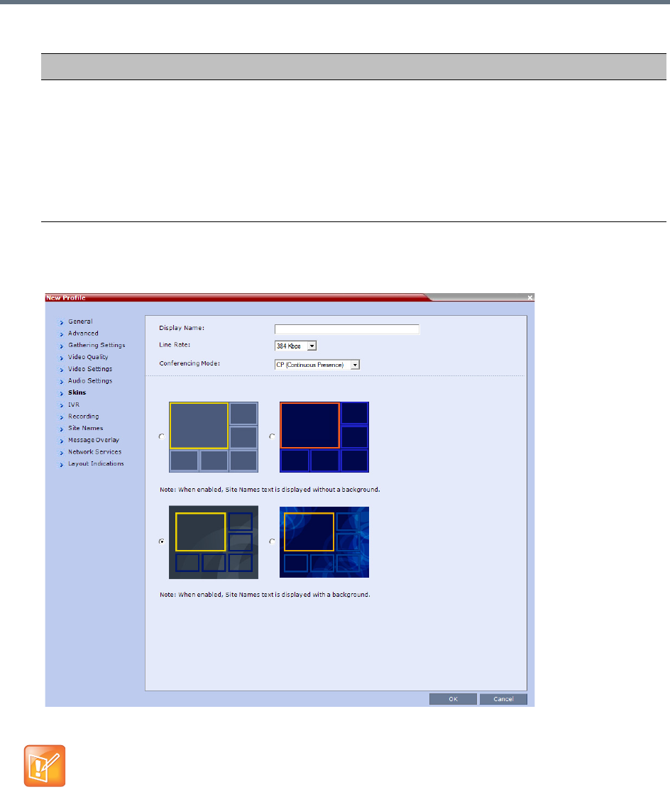
Defining AVC-Based Conference Profiles
Polycom®, Inc. 63
16 Click the Skins tab to modify the background and frames.
The New Profile - Skins dialog box opens.
17 Select one of the Skin options.
Auto mute noisy
endpoints
This option is automatically enabled in new Profiles. When enabled, the RMX can
detect AVC endpoints with a noisy audio channel and automatically mute them,
reducing the noise heard by other conference participants. When the auto muted
endpoint becomes the “speaker” the endpoint is automatically un-muted by the
system. If the speaker halts his/her conversation and the line still emits noises, the
endpoint will be automatically muted again.
Clear this check box to disable the feature.
For more details, see Automatic Muting of Noisy Endpoints.
•In Classic View (for the first two skin options) the frames fill the screen with their borders touching.
•When Telepresence Mode is enabled, the Skin options are disabled as the system uses a black
background and the frames and speaker indication are disabled.
New AVC CP Profile - Audio Settings Parameters
Field/Option Description
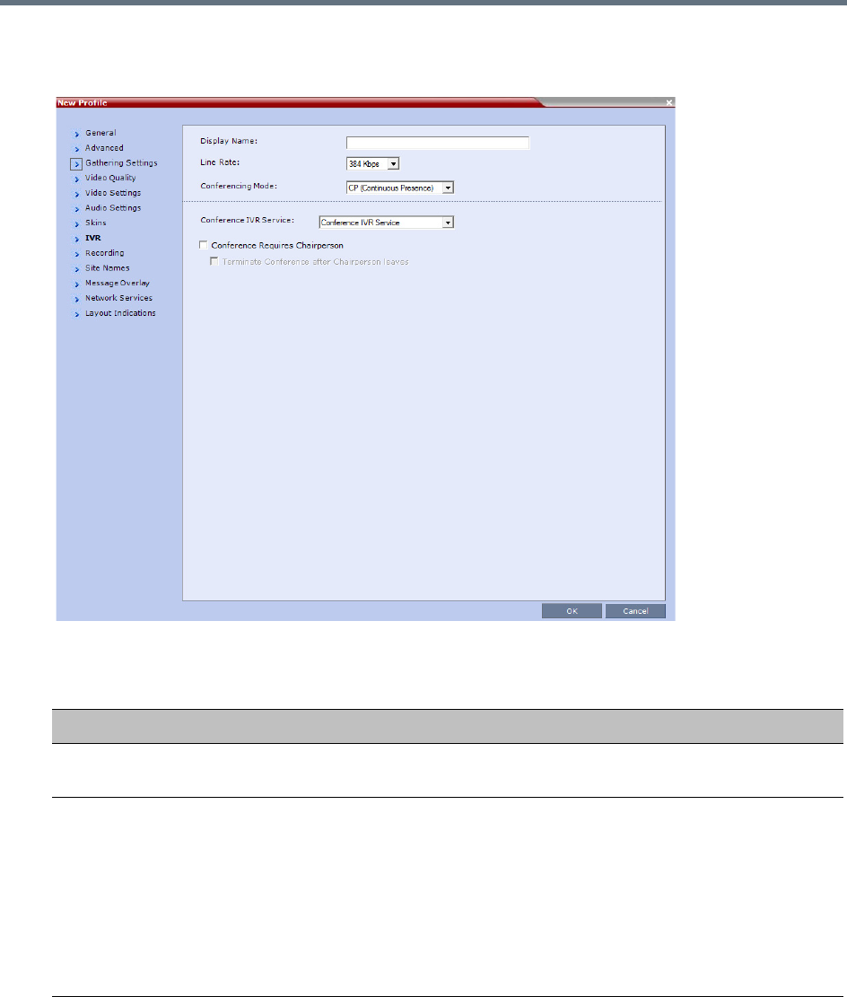
Defining AVC-Based Conference Profiles
Polycom®, Inc. 64
18 Click the IVR tab.
The New Profile - IVR dialog box opens.
19 If required, set the following parameters:
New AVC CP Profile - IVR Parameters
Field/Option Description
Conference IVR
Service
The default conference IVR Service is selected. You can select another conference
IVR Service if required.
Conference Requires
Chairperson
Select this option to allow the conference to start only when the chairperson
connects to the conference and to automatically terminate the conference when the
chairperson exits. Participants who connect to the conference before the
chairperson are placed on Hold and hear background music (and see the Welcome
video slide). Once the conference is activated, the participants are automatically
connected to the conference.
When the check box is cleared, the conference starts when the first participant
connects to it and ends at the predefined time or according to the Auto Terminate
rules when enabled.
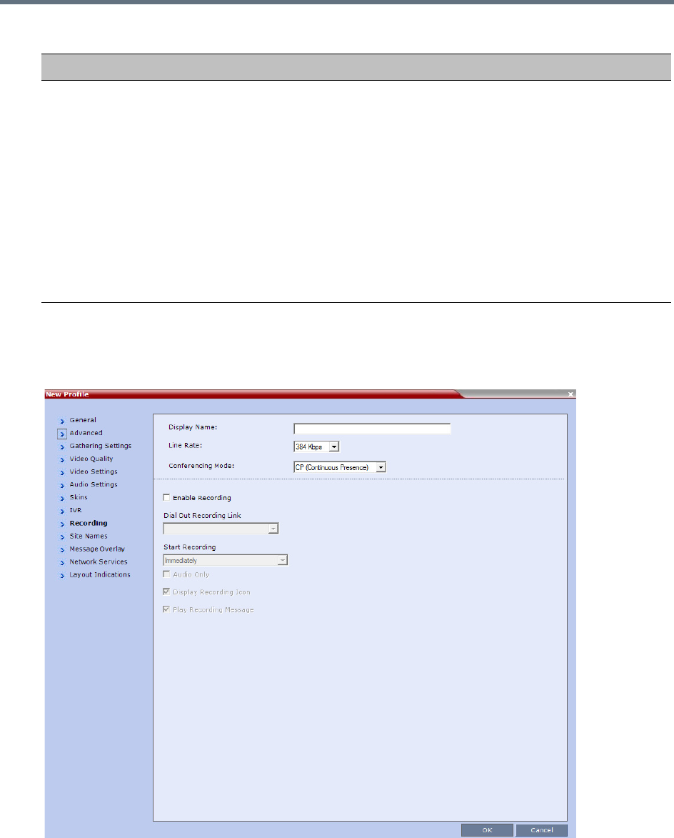
Defining AVC-Based Conference Profiles
Polycom®, Inc. 65
20 Optional. Click the Recording tab to enable conference recording with Polycom RealPresence
Capture Server or RSS 4000 system.
The New Profile - Recording dialog box opens.
Terminate conference
after chairperson
leaves
Select this check box to automatically terminate the conference after the
chairperson leaves. When the chairperson leaves, the Chairperson Has Left
IVR message is played to (heard by) all participants, at which point the conference
terminates. This way an operator does not need to monitor a conference to know
when to terminate it manually.
If there is a single chairperson in the conference who is changed to a regular
participant the conference will be terminated as if the chairperson left. If there is
more than one chairperson, then changing one chairperson to a regular participant
will not terminate the conference. It is therefore recommended that before changing
a single chairperson to regular participant, another participant first be changed to
chairperson.
Terminate Conference After Chairperson Leaves is not supported in cascaded
environments.
New AVC CP Profile - IVR Parameters
Field/Option Description
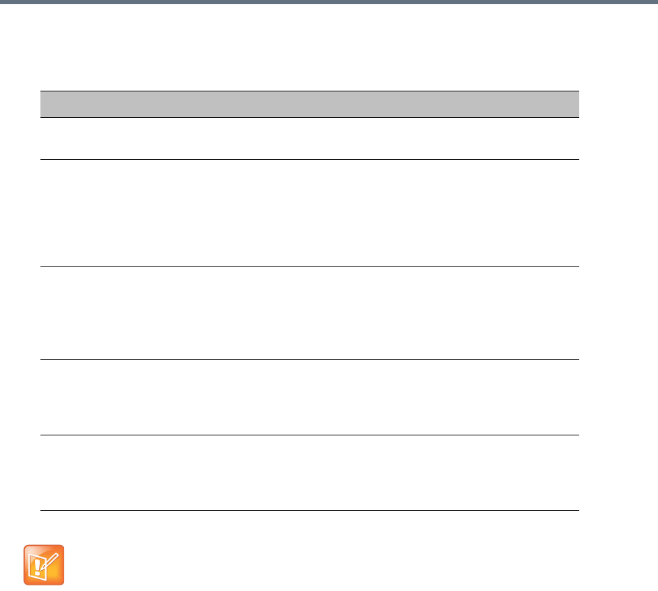
Defining AVC-Based Conference Profiles
Polycom®, Inc. 66
21 Define the following parameters:
New AVC CP Profile - Recording Parameters
Parameter Description
Enable Recording Select this check box to enable the Recording of the conference. If no
Recording Links are found, an error message is displayed.
Dial Out Recording
Link
Select the Recording Link to be used for conference recording.
Recording Links defined on the Collaboration Server can be given a
descriptive name and can be associated with a Virtual Recording
Room (VRR) saved on the Polycom® RealPresence® Capture
Server or RSS 4000system. For more information see Recording and
Streaming Conferences
Start Recording Select when to start the recording:
• Immediately – Conference recording is automatically started upon
connection of the first participant.
• Upon Request – The operator or chairperson must initiate the
recording (manual).
Audio Only Select this option to record only the audio channel of the conference.
Note: This option can be used only if there are Voice ports configured
in the Video/Voice Port Configuration. For more information, see
Video/Voice Port Configuration - MPMx.
Display Recording
Icon
This option is automatically selected to display a Recording Indication
to all conference participants informing them that the conference is
being recorded.
Clear the selection to prevent the display of the recording icon.
The Recording link (which is listed as a participant in the conference) does not support H.264 High
Profile. If recording a conference that is set to H.264 High Profile, the Recording participant connects
as Audio Only and records only the conference Audio.
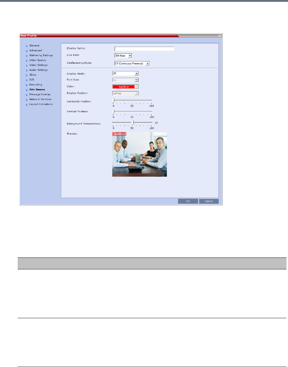
Defining AVC-Based Conference Profiles
Polycom®, Inc. 67
22 Click the Site Names tab.
The New Profile - Site Names dialog box opens.
Using the Site Name dialog box, you can control the display of the site names by defining the font,
size, color, background color and transparency and position within the Video Window. For a detailed
description of the site names options see Site Names Definition.
23 Define the following parameters:
New AVC CP Profile - Site Names Parameters
Field Description
Display Mode Select the display mode for the site names:
•Auto - Display the Site Names for 10 seconds whenever the Video Layout
changes.
•On - Display the Site Names for the duration of the conference.
•Off (default) - Do not display the Site Names and all other fields in this tab are
grayed and disabled
Font Size Click the arrows to adjust the font size (in points) for the display of Site Names.
Choose a Font Size that is suitable for viewing at the conference’s video resolution.
For example, if the resolution is CIF, a larger Font Size should be selected for
easier viewing.
Range: 9 - 32 points
Default: 12 points
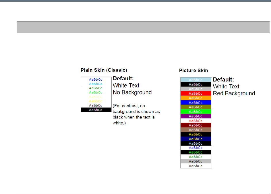
Defining AVC-Based Conference Profiles
Polycom®, Inc. 68
Background Color Select the color of the Site Names display text.
The color and background for Site Names display text is dependent on whether a
Plain Skin or a Picture Skin was selected for the conference in the Profile - Skins
tab. The choices are:
Note: Choose a Background Color combination that is suitable for viewing at the
conference’s video resolution. At low resolutions, it is recommended to select
brighter colors as dark colors may not provide for optimal viewing.
New AVC CP Profile - Site Names Parameters
Field Description
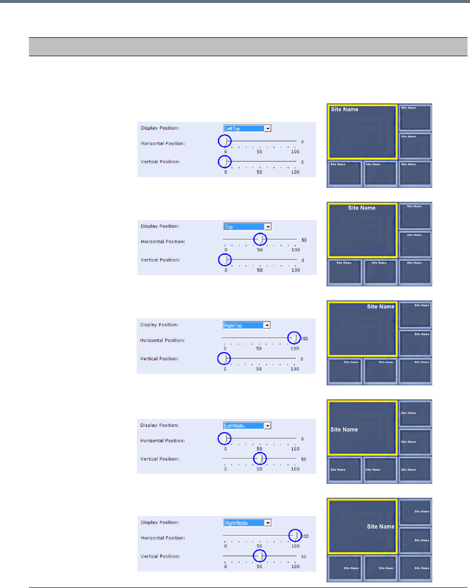
Defining AVC-Based Conference Profiles
Polycom®, Inc. 69
Display Position Select the pre-set position for the display of the Site (endpoint) Names.
Selection Site Names Position
LeftTop (Default)
Top
RightTop
LeftMiddle
RightMiddle
New AVC CP Profile - Site Names Parameters
Field Description
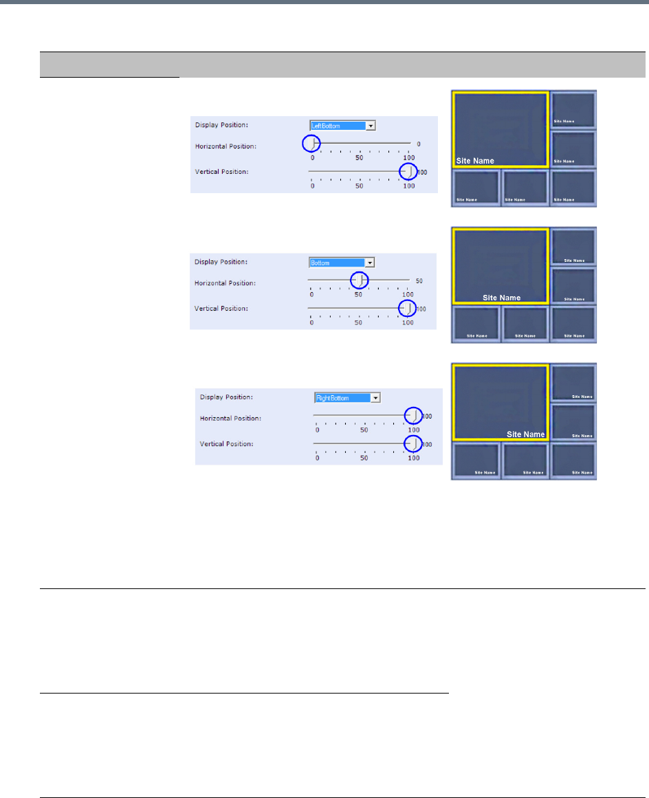
Defining AVC-Based Conference Profiles
Polycom®, Inc. 70
Display Position
(cont.)
LeftBottom
Bottom
RightBottom
Custom The current endpoint (site)
names display position becomes
the initial position for Site Names
position adjustments using the
Horizontal and Vertical
Position sliders.
Horizontal Position Move the slider to the left to move the
horizontal position of the endpoint (site)
names to the left within the video windows.
Move the slider to the right to adjust the
horizontal position of the endpoint (site)
names to the right within the video windows.
Note: Use of these sliders will
set the Display Position
selection to Custom.
Vertical Position Move the slider to the left to move the vertical
position of the Site names upward within the
Video Windows.
Move the slider to the right to move the
vertical position of the endpoint (site) names
downward within the video windows.
New AVC CP Profile - Site Names Parameters
Field Description
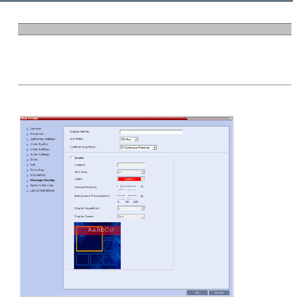
Defining AVC-Based Conference Profiles
Polycom®, Inc. 71
24 Click the Message Overlay tab.
The New Profile - Message Overlay dialog box opens.
Message Overlay enables you to send text messages to all participants during ongoing Continuous
Presence conferences.
The text message is seen as part of the in the participant’s video layout on the endpoint screen or
desktop display.
For more details, see Sending Text Messages During a Conference Using Message Overlay.
Background
Transparency
Move the slider to the left to decrease the transparency of the background of the
endpoint (site) names text. 0 = No transparency (solid background color).
Move the slider to the right to increase the transparency of the background of the
endpoint (site) names text. 100 = Full transparency (no background color).
Default: 50
Note: This slider is only displayed if a Picture Skin is selected.
New AVC CP Profile - Site Names Parameters
Field Description
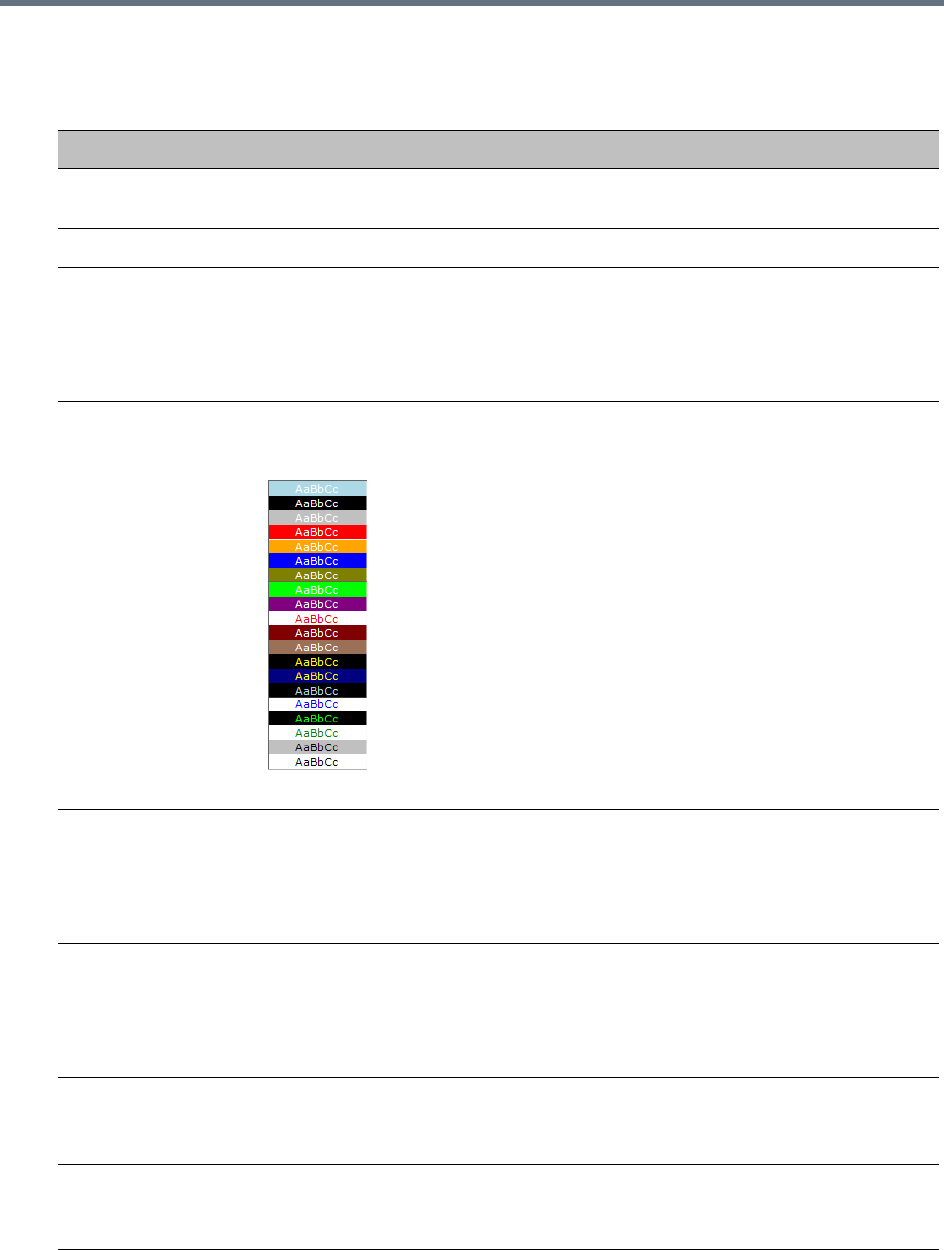
Defining AVC-Based Conference Profiles
Polycom®, Inc. 72
25 Define the following fields:
New AVC CP Profile - Message Overlay Parameters
Field Description
Enable This option is disabled by default. Select this check box to enable Message Overlay
or clear it to disable it.
Content Enter the message text. The message text can be up to 50 Chinese characters.
Font Size Click the arrows to adjust the font size (points) for the display of the message text.
Font size range: 9 - 32 points, default: 24 points
Note: In some languages, for example Russian, when a large font size is selected,
both rolling and static messages may be truncated if the message length exceeds
the resolution width.
Color From the drop-down menu select the color and background of the displayed text.
The choices are:
Default: White text on red background.
Vertical Position Move the slider to the right to move the vertical position of the displayed text
downward within the Video Layout.
Move the slider to the left to move the vertical position of the displayed text upward
within the Video Layout.
Default: Top Left (10)
Background
Transparency
Move the slider to the left to decrease the transparency of the background of the
message text. 0 = No transparency (solid background color).
Move the slider to the right to increase the transparency of the background of the
message text. 100 = Full transparency (no background color).
Default: 50
Display Repetition Click the arrows to increase or decrease the number of times that the text message
display is to be repeated.
Default: 3
Display Speed Select whether the text message display is static or moving across the screen, the
speed in which the text message moves: Static, Slow, Fast
Default: Slow
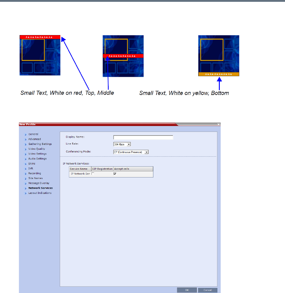
Defining AVC-Based Conference Profiles
Polycom®, Inc. 73
As the fields are modified the Preview changes to show the effect of the changes.
For example:
26 Click the Network Services tab.
The New Profile - Network Services dialog box opens.
Registration of conferencing entities such as ongoing conferences, Meeting Rooms, Entry Queues,
SIP Factories, and Gateway Sessions with SIP servers is done per conferencing entity. This allows
better control on the number of entities that register with each SIP server.
Selective registration is enabled by assigning a conference Profile in which registration is configured
to the required conferencing entities. Assigning a conference Profile in which registration is not
configure to conferencing entities will prevent them from registering.
By default, Registration is disabled in the Conference Profile, and must be enabled in Profiles
assigned to conferencing entities that require registration.
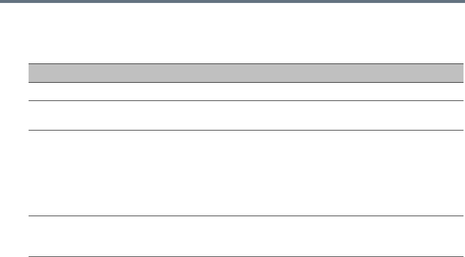
Defining AVC-Based Conference Profiles
Polycom®, Inc. 74
27 Define the following parameters:
New AVC CP Profile - Network Services Parameters
Parameter Description
IP Network Services
Service Name This column lists all the defined Network Services, one or several depending on the
system configuration.
SIP Registration To register the conferencing entity to which this profile is assigned with the SIP
Server of the selected Network Service, click the check box of that Network Service
in this column.
When SIP registration is not enabled in the conference profile, the Collaboration
Server's registering to SIP Servers will each register with an URL derived from its
own signaling address. This unique URL replaces the non-unique URL,
dummy_tester, used in previous versions.
Accept Calls To prevent dial in participants from connecting to a conferencing entity when
connecting via a Network Service, clear the check box of the Network Service from
which calls cannot connect to the conference.
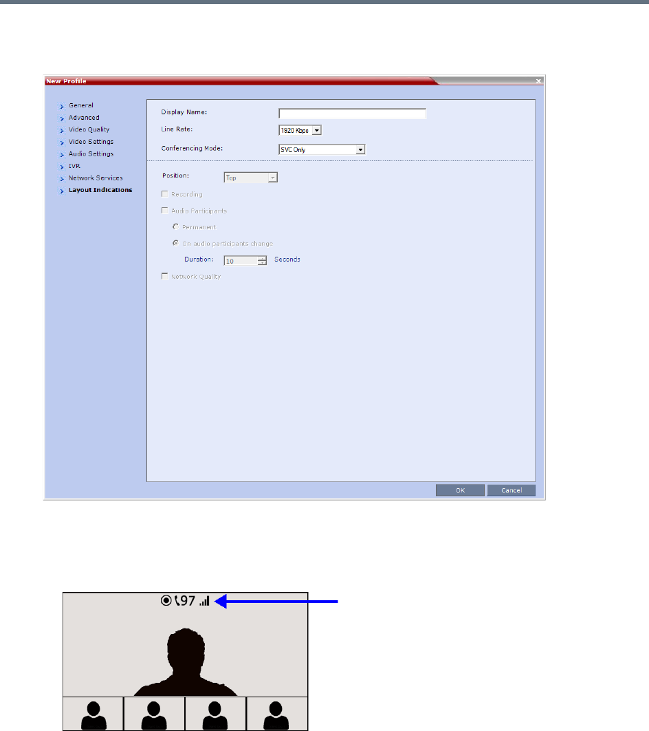
Defining AVC-Based Conference Profiles
Polycom®, Inc. 75
28 Click the Layout Indications tab.
The Layout Indications dialog is displayed.
The Layout Indications are displayed in the conference video layout as an icon group that includes:
Recording
Audio Participants
Network Quality

Defining AVC-Based Conference Profiles
Polycom®, Inc. 76
29 Modify the following parameters to configure the display, position, and duration of the indication
icons.
30 Click OK to complete the Profile definition.
A new Profile is created and added to the Conference Profiles list.
The Layout Indications tab is only displayed if either AVC-CP or AVC-CP and SVC (mixed mode) is
selected.
Beginning with version 8.4, the configuration options of the Layout Indications tab have replaced the
following system flags:
•DISABLE_SELF_NETWORK_IND
•SELF_IND_LOCATION
For further information on layout indications see Layout Indications.
New AVC CP Profile - Layout Indications Parameters
Field Description
Position Use the Position drop-down menu to configure the display position of the indication
icons group. Icons can be displayed in the following positions:
•Top-left
•Bottom-left
•Top center (default)
•Bottom
•Top-right
•Bottom-right
Recording Select the check box to display the Recording icon.
The Recording indication icon is a duplicate of the Display Recording Icon field in the
Recording tab of the Profile dialog.
For more information, see Recording and Streaming Conferences.
Audio Participants Select the check box to display the Audio Participants icon.
• Permanent - Sets the Audio Participant Indication to display permanently. In this
setting it is only displayed when audio participants are connected.
• On audio participants change - Sets the Audio Participant Indication to display for
a short period only when the number of audio participants changes.
Duration - Sets the amount of time the Audio Participant icon displays.
For more information see Audio Participants Indication.
Network Quality To display the Network Quality icon, select the check box.
For more information see Network Quality Indication.
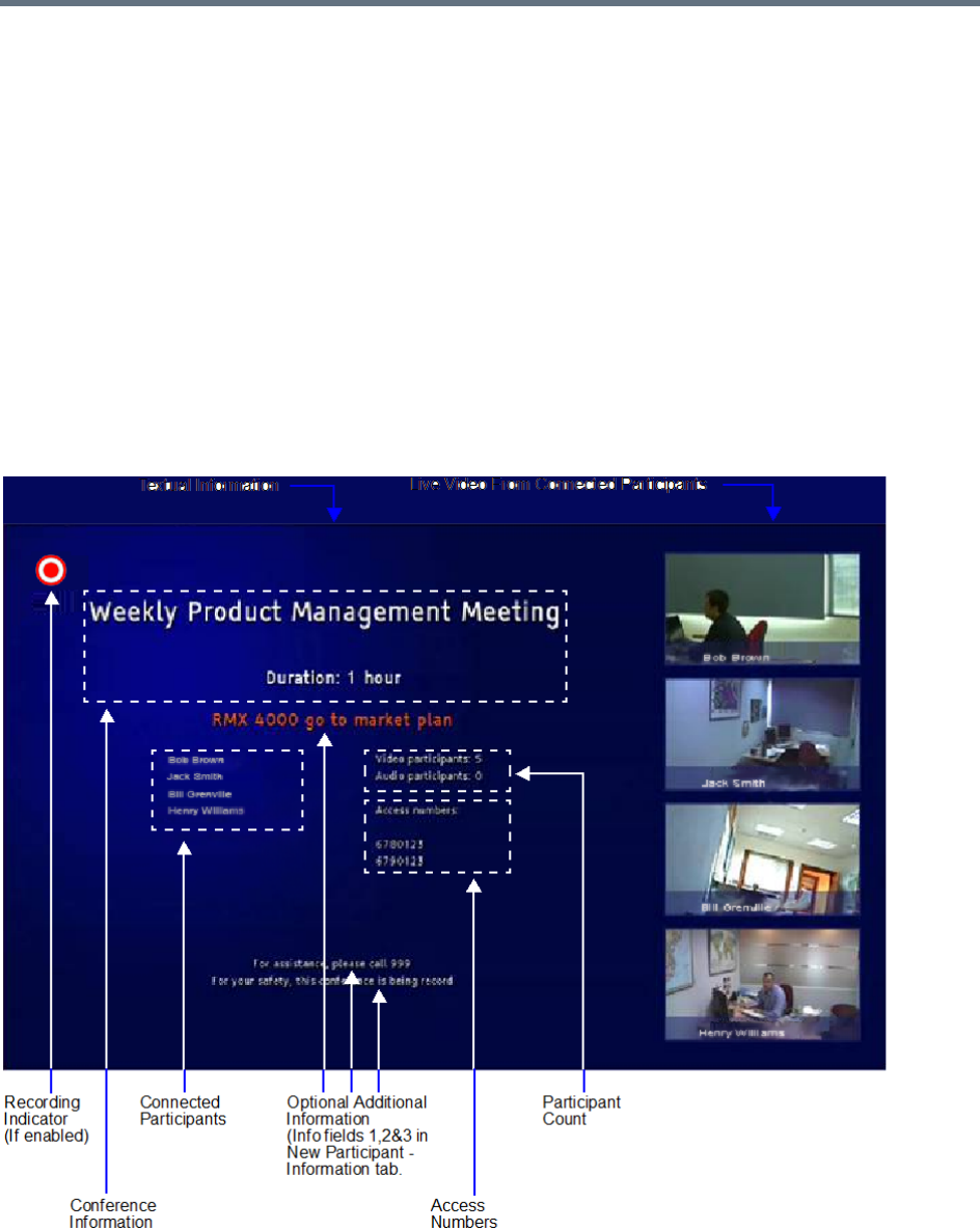
Defining AVC-Based Conference Profiles
Polycom®, Inc. 77
Additional Information for Setting CP Profiles
This section includes detailed explanation of various CP Profile settings:
●Gathering Phase
●Overlay Layouts
●Site Names Definition
●Sending Text Messages During a Conference Using Message Overlay
●Selecting the Chinese Font for Text Display
Gathering Phase
The Gathering Phase of an AVC (CP only) conference is the time period during which participants are
connecting to a conference. During the Gathering Phase, a mix of live video from connected endpoints is
combined with both static and variable textual information about the conference into a slide which is
displayed on all connected endpoints.

Defining AVC-Based Conference Profiles
Polycom®, Inc. 78
During the Gathering Phase, the audio of all participants can be heard, and the video of active speakers is
displayed in the video windows as they begin talking.
All connected participants are kept informed about the current conference status including names of
connected participants, participant count, participant type (video/audio) etc.
Gathering Phase Guidelines
●Gathering Phase is only available in AVC only (CP only) conferences. It is not supported in Video
Switching conferences and SVC Only conferences.
●The Gathering Phase slide can be displayed at any time during the conference by entering the Show
Participants DTMF code, *88.
Note: When the display of the Gathering Phase slide is removed, the message overlay text is also
removed.
●The names of the first eight participants to connect are displayed. If eight or more participants
connect, the 8th row displays “…”.
●Static text in the Gathering Phase slide such as the field headings: Organizer, Duration, Video/Audio
Participants, Access Number, IP are always displayed in the language as configured in the Polycom
Virtual Meeting Rooms Add-in for Microsoft Outlook. The following languages are supported:
English
French
German
International Spanish
Korean
Japanese
Simplified Chinese
●Dynamic text in the Gathering Phase slide such as the meeting name, participants’ names, access
numbers and the additional information entered in the Info1/2/3 fields of the Gathering Settings tab
of the conference Profile are displayed in the language of the meeting invitation.
●The language of a Gathering Phase slide of a conference configured to include a Gathering Phase
that is not launched by the Polycom Conferencing Add-in for Microsoft Outlook is configured by the
administrator. Using the Collaboration Server Web Client, the administrator selects the language for
the Gathering Phase slide. The language selected can be different to that of the Collaboration Server
Web Client used by the administrator to perform the configuration.
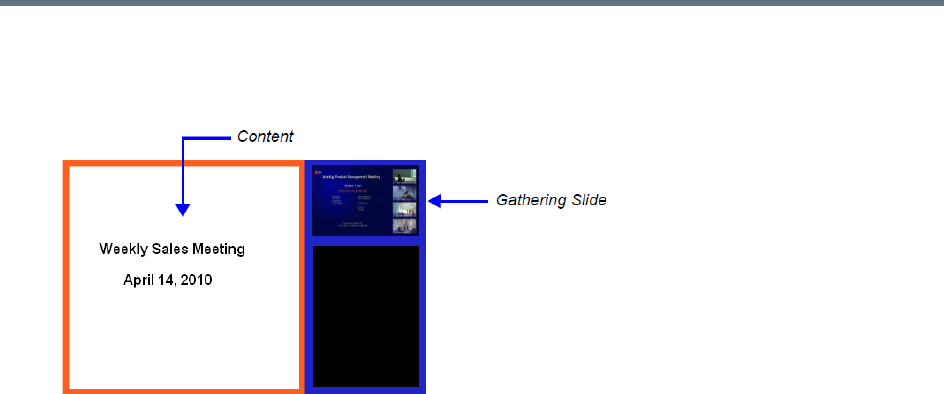
Defining AVC-Based Conference Profiles
Polycom®, Inc. 79
●Content can be sent during the Gathering Phase. The content is displayed in the large video window
of the participant’s layout while the Gathering slide is displayed in a smaller video window in the
layout.
●Gathering is not supported in Cascading Conferences.
Gathering Phase Duration
The duration of the Gathering Phase can be customized by the administrator so that it is long enough to be
viewed by most connected participants yet short enough so as not to over extend into the scheduled
conferencing time.
The Gathering Phase duration is configured for the Collaboration Server, by the following System Flags in
system.cfg in the Setup > System Configuration:
●CONF_GATHERING_DURATION_SECONDS
Range: 0 - 3600 seconds
Default: 180 seconds
The Gathering Phase duration of the conference is measured from the scheduled start time of the
conference.
Example: If the value of the flag is set to 180, the Gathering slide is displayed for three minutes to all
participants starting at the conference Start Time, and ending three minutes after the conference Start
Time.
For participants who connect before Start Time, the Gathering slide is displayed from the time of
connection until the end of the Gathering duration period.
●PARTY_GATHERING_DURATION_SECONDS
Range: 0 - 3600 seconds
Default: 15 seconds
The value of this flag determines the duration of the display of the Gathering slide for participants that
connect to the conference after the conference Start Time.
Participants connecting to the conference very close to of the end of the Gathering Phase (when there
are fewer seconds left to the end of the Gathering Phase than specified by the value of the flag) have
the Gathering slide displayed for the time specified by the value of the flag.
Example: If the value of the flag is set to 15, the Gathering Phase slide is displayed to the participant
for 15 seconds.
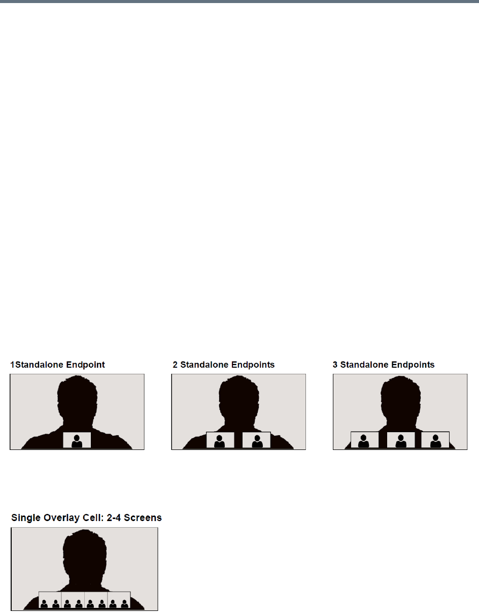
Defining AVC-Based Conference Profiles
Polycom®, Inc. 80
Enabling the Gathering Phase Display
The Gathering Phase is enabled for per conference in the Conference Profile. The profile also includes the
dial-in numbers and the optional additional information to display on the slide.
Conferences that are configured to include a Gathering Phase that are not launched by the Polycom
Conferencing Add-in for Microsoft Outlook need the following information to be entered via the New Profile
or Profile Properties — Gathering Settings dialog box:
●Display Name (Optional, the Meeting Name is used if left blank.)
●Displayed Language
●Access Number 1 / 2 (Optional.)
●Additional Information (Optional free text)
Info 1
Info 2
Info 3
Conferences launched by the Polycom Conferencing Add-in for Microsoft Outlook receive this information
from the meeting invitation.
For more information see Defining New Profiles.
Overlay Layouts
In Overlay Layouts additional participant endpoints can be displayed over the full screen display of the
conference speaker.
The following Overlay Layouts are available for use in CP Conferences:
Although the following Overlay Layout is included in the Profiles - Video Settings dialog box, it is not
available for use in any Conferencing Mode and is only available when included in the Polycom® Multipoint
Layout (MLA) application:

Defining AVC-Based Conference Profiles
Polycom®, Inc. 81
Guidelines for using the Overlay Layouts
●The Overlay Layouts are supported:
In CP Conferencing Mode only.
With ITP, non-ITP and CTS endpoints used only as standard endpoints.
With both new and classic Skins in Collaboration Server CP mode.
●Overlay Layouts are not supported in ITP conferences as they are not supported by the MLA
application.
●The Overlay Layouts are 20% of the height of the endpoint display and are supported on endpoints
of both 16:9 and 4:3 aspect ratios.
●Overlay Layouts are recommended for use with high resolution endpoints.
●Overlay Layouts are not selected as defaults by the system and are not included in the Auto Layout
settings.
●Message Overlay is not affected by the use of Overlay Layouts and is displayed on top of the video
layouts.
●Site Names are displayed for all cells. Because the smaller cells are located at the bottom of the large
cell, when enabling Site Names it is advisable not to locate the Site Name at the bottom of the cells.
●Standalone Endpoint Cells are displayed each with a border. For all Overlay Layouts, border color is
dependent on the selected Skin.
●System behavior for Video Forcing and Personal Layout Control when using the Overlay Layouts
during an ongoing conference is the same as for other video layouts.
●Overlay Layouts are only available for selection for the Conference Layout and are not available for
selection for Personal Layout.
●During an ongoing conference you cannot select the Overlay Layouts via PCM or Click&View.
●PCM menus can be used when the Overlay Layouts are active, and they are displayed as the top
layer.
These Overlay Layouts will only be available in ITP (Telepresence) conferences when support for
Overlay Layouts is included in the Polycom® Multipoint Layout (MLA) application.
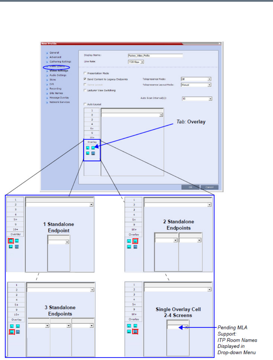
Defining AVC-Based Conference Profiles
Polycom®, Inc. 82
Selecting the Overlay Layouts
The Overlay Layouts are selected in the New Profile - Video Settings dialog box, in the Overlay tab of the
Video Layout tree.
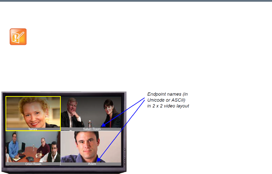
Defining AVC-Based Conference Profiles
Polycom®, Inc. 83
Site Names Definition
During conferences you can view the names of the endpoints that are connected to the conference in your
endpoint video layout windows. The MCU can display up to 33 characters of the endpoint name, depending
on the window layout (size).
The following is an example of endpoint name display in the endpoint screen:
The display of the site names is enabled or disabled in the conference Profile for CP Only or Mixed CP and
AVC conferences for AVC-based endpoints.
SVC-based endpoints handle the display of the site names themselves and are not dependant on the
conference Profile. The Site Names option is not supported in Video Switching conferences.
The displayed name is determined as follows:
●The system displays the name that is defined at the endpoint.
●If the endpoint does not send its name:
For a defined H.323 or SIP participant:
The system displays the name from the participant definition.
For an undefined H.323 participant:
Display the H.323 ID alias.
or
Display the E.164 alias.
or
Display nothing if all the fields are empty.
For a SIP undefined participant:
The Site Names feature is not supported on the Collaboration Server (RMX) 1800.

Defining AVC-Based Conference Profiles
Polycom®, Inc. 84
Display the SIP DisplayName field.
or
Display the SIP Address (SIP application server).
or
Display the SIP ContactDisplay field.
or
Display nothing if all the fields are empty.
For a defined H.320 participant (Collaboration Server 1500/2000/4000):
The system displays the name from the participant definition.
For an undefined H.320 participant:
Display the Terminal Command String (TCS-2) to identify the participant.
or
Display nothing if the string is not received or empty.
●If the endpoint Display Name is changed in the Collaboration Server Web Client, it overrides all the
above.
You can control the display of the site names by defining the font, size, color, background color and
transparency and position within the video window in the Profile - Site Name dialog box.
Guidelines
●Site Names display is Off by default in a new profile.
●Site Names can be enabled to function in one of two modes:
Auto – Site names are displayed for 10 seconds whenever the conference layout changes.
On – Site names are displayed for the duration of the conference.
●During the display of the site names, the video frame rate is slightly reduced
●Site Names display is not available for Video Switching (VSW) conferences.
●Site Names display characteristics (position, size, color) can by modified during an ongoing
conference using the Conference Properties - Site Names dialog box. Changes are immediately
visible to all participants.
●Site Names display text and background color is dependent on the Skin selected for the conference:
Plain Skins - Site Names text is displayed without a background.
Picture Skins - Site Names text is displayed with a background.
Shorten the Site Name Display
The SIP_OMIT_DOMAIN_FROM_PARTY_NAME System Flag can be used to remove Domain Names
from SIP dial-in participants’ Site Names. This prevents long domain names being appended to SIP
participant names, as frequently happens when the Collaboration Server is used with a DMA.
The flag must be manually added to the System Configuration and its value modified as follows:
●YES (Default) - The domain name is omitted from SIP dial-in participant names.
●NO - The domain name remains as part of SIP dial-in participant names.
For more information, see
Modifying System Flags
.
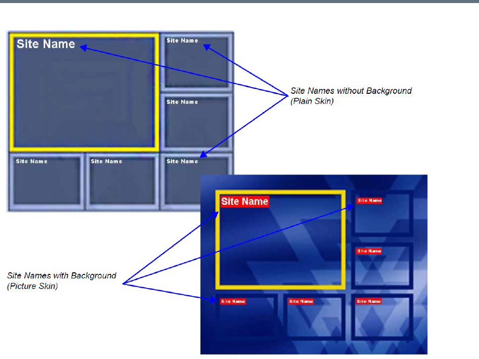
Defining AVC-Based Conference Profiles
Polycom®, Inc. 85
Site Names Display Position
The position of the Site Names displayed during the conference is controlled in the Profile - Site Names tab.
The following options can be used to define the display position:
●Display Position drop-down menu - To select a preset position.
●Horizontal Position and Vertical Position sliders - To move them to customize the preset position.
Dragging the sliders sets the Display Position drop-down menu field value to Custom.
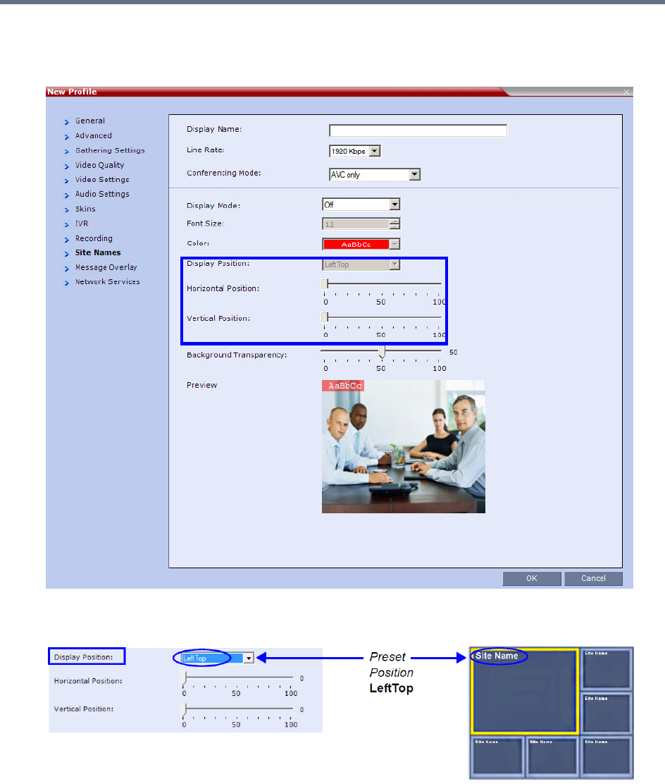
Defining AVC-Based Conference Profiles
Polycom®, Inc. 86
●Selecting Custom in Display Position drop-down menu. When selected, the current position
becomes the initial position for position adjustments and then using the Horizontal and Vertical
Position sliders to define the exact position.
The adjusted position of the Site Names can be viewed in the Preview.
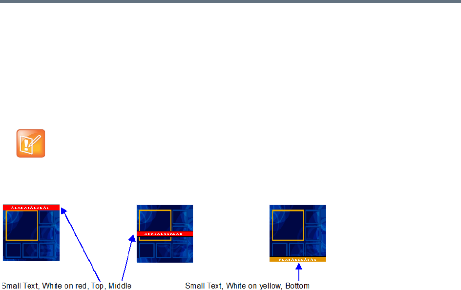
Defining AVC-Based Conference Profiles
Polycom®, Inc. 87
Sending Text Messages During a Conference Using Message Overlay
The Message Overlay option in the Conference Profile allows the operator or administrator to send text
messages to a single participant, a number of selected participants or all participants during an ongoing
conference.
The number of characters that can be included in a message varies according to the language and can differ
due to the type of font used. For example, the available number of characters in Chinese is 50 (32 for
Collaboration Server 1800) for English and 50 (48 for Collaboration Server 1800) and for Russian.
The message can be set to be displayed at various positions on the screen in different colors, static or
scrolling.
Guidelines
●Text messaging using Message Overlay is supported in:
MPMx and MPMRx Card Configuration Modes
Continuous Presence (CP) conferences
Same Layout mode
Encrypted conferences
Unicode or ASCII characters
●Text messages using Message Overlay cannot be displayed:
In Video Switching (VSW) conferences.
In Lecture Mode
When the PCM menu is active
On endpoints that have their video suspended
●Text messaging using Messages Overlay can be enabled, disabled or modified (content and display
parameters) during the ongoing conference.
●The number of characters for each language can vary due to the type of font used, for example, the
available number of characters for Chinese is 18, while for English and Russian it is 48.
In some languages, for example Russian, when large font size is selected, both rolling and static
messages may be truncated if the message length exceeds the resolution width.
●Changes to the Message Overlay Content or display characteristics (position, size, color and speed)
are immediately visible to all participants. When there is a current Message Overlay:
In some languages, for example Russian, when a large font size is selected, both rolling and static
messages may be truncated if the message length exceeds the resolution width.
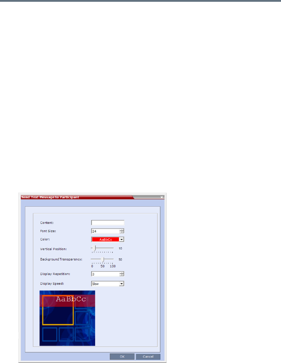
Defining AVC-Based Conference Profiles
Polycom®, Inc. 88
The current message is stopped immediately, even it has not completed all of its repetitions.
The Display Repetition count is reset to 1.
The new message content is displayed <Display Repetition> times or until it is stopped and
replaced by another content change.
●If during the ongoing conference the Show Number of Participants DTMF option (default DTMF
*88) is used, when the displayed number of participants is removed, the message overlay text is also
removed.
●The text messages cannot be sent via the Content channel.
●Message Overlay text settings are not saved in the Conference Template when saving an ongoing
conference as a Conference Template.
For a detailed description of all the Message Overlay parameters, see New AVC CP Profile - Message
Overlay Parameters.
Sending Messages to All Conference Participants using Message Overlay
To send messages to all conference participants Using Message Overlay:
1In the Conferences List pane, double click the name of the conference to have Message Overlay
enabled or right-click the conference name and then click Conference Properties.
2Click the Message Overlay tab.
3Select the Enable check box.
The Send Text Message to Participant dialog box is displayed.

Defining AVC-Based Conference Profiles
Polycom®, Inc. 89
4In the Content field, enter the text to be displayed to all the conference participants.
5Modify the remaining fields in the dialog box to display the message as required.
6Click OK
To cancel the Message Overlay display:
1In the Conferences List pane, double click the name of the conference to have Message Overlay
enabled or right-click the conference name and then click Conference Properties.
2Click the Message Overlay tab.
3Clear the Enable check box.
4Click OK.
Sending Messages to Selected Participants Using Message Overlay
To send text to selected participants:
1In the Participant List pane, choose a participant or a number of participants.
2In the Participant List pane, right-click a participant or a number of participants and then select Send
Text Message to Participant.
The rest of configuration steps are the same with what in sending messages to all conference
participants, see Sending Messages to All Conference Participants using Message Overlay.
Selecting the Chinese Font for Text Display
When using the RMX Web Client or the RMX Manager in Chinese (either Simplified Chinese or Traditional
Chinese is selected as an available language in the Setup > Customize Display Settings > Multilingual
Setting, you can select one of several Chinese fonts for use when sending text over video. The font is used
to display text for the following:
●Display of Site Names
●Test messages sent using Message Overlay
●Text displayed on the Gathering slide when Chinese is selected as the display language
Selecting the Chinese Font
The Chinese fonts can be selected in the CP Conference Profile - Advanced dialog box only.
When sending text messages using Message Overlay and stopping the text messaging in the
middle, you must change (and then cancel the change) one of the message overlay properties in the
Conference Properties - Message Overlay dialog box before you can re-send the same message.
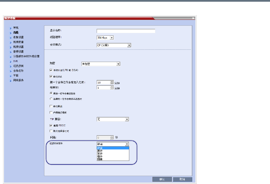
Defining AVC-Based Conference Profiles
Polycom®, Inc. 90
The following Chinese fonts are available for selection:
●Heiti (Default)
●Songti
●Kaiti
●Weibei
The Chinese font cannot be changed during an existing conference. It can only be modified in the
conference profile.
A participant moved to another conference will be shown the font used by the new conference.
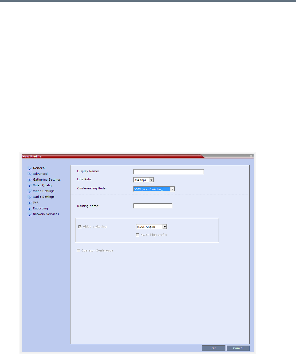
Defining AVC-Based Conference Profiles
Polycom®, Inc. 91
Defining an AVC Video Switching Conference Profile
An AVC Video Switching-enabled Profile must be created prior to running Video Switching conferences.
This profile can be assigned to Meeting Rooms, conferences, reservations and Entry Queues
To connect to a Video Switching conference via an Entry Queue, the Entry Queue must be Video Switching
enabled and must be set to the same line rate as the target conference. It is recommended to use the same
Profile for both the target conference and Entry Queue.
Video Switching conferencing mode is unavailable to ISDN participants.
When the Conferencing Mode is set to Video Switching, only the tabs and fields relevant to Video Switching
conferences are displayed and enabled.
To Create a Video Switching Profile:
1In the RMX Management pane, click Conference Profiles.
2In the Conference Profiles pane, click the New Profile button.
The New Profile – General dialog box opens.
Defining AVC-Based Conference Profiles
Polycom®, Inc. 92
3Define the New Profile - General parameters:
New AVC VSW Profile - General Parameters
Field/Option Description
Display Name Enter a unique Profile name, as follows:
•
English text uses ASCII encoding and can contain the most characters (length
varies according to the field).
•European and Latin text length is approximately half the length of the maximum.
•Asian text length is approximately one third of the length of the maximum.
It is recommended to use a name that includes the Profile type, such as Weekly
Video Switching conference.
Note: This field is displayed in all tabs.
Line Rate Select the conference bit rate. The line rate
represents the combined video, audio
and Content rate
.
When defining a VSW profile, select a line rate that all connecting participants can
use. Participants that their endpoint or network that do not support this line rate
cannot connect to the conference or will connect as Audio Only (if resources were
designated as Voice ports).
If a high definition resolution will be selected for the conference video, make sure
that the selected line rate is higher than the minimum line rate threshold defined in
the flag HD_THRESHOLD_BITRATE for Video Switching conferences.
The default setting is 384 Kbps.
Note: This field is displayed in all tabs.
Conferencing Mode Select VSW (Video Switching) to define a VSW conference Profile.
Note: This field is displayed in all tabs.
Routing Name Enter the Profile name using ASCII characters set.
The Routing Name can be defined by the user or automatically generated by the
system if no Routing Name is entered as follows:
•If an all ASCII text is entered in Display Name, it is used also as the Routing
Name.
•If any combination of Unicode and ASCII text (or full Unicode text) is entered in
Display Name, the ID (such as Conference ID) is used as the Routing Name.
Defining AVC-Based Conference Profiles
Polycom®, Inc. 93
4Define the various Profile parameters for a Video Switching conference. As it is an AVC -bases
conferencing mode, many of the fields and options are identical to the CP Profile. For more
information, see Defining AVC CP Conferencing Profiles.
The following AVC-based conferencing options are not available in VSW conferences:
Operator Conference
Gathering Phase
Video Quality - Send Content To Legacy Endpoints
Video Settings:
Presentation Mode
Auto Layout/Same Layout (only full screen, 1x1 layout display is available)
Video Switching This check box is automatically selected when the Conferencing Mode is set to
Video Switching.
Select the video protocol and resolution for the conference:
•H.264 1080p60
•H.264 1080p30
•H.264 720p60
•H.264 720p30
•H.264 SD 30
•H.264 CIF
•H.263 CIF
•H.261 CIF
All participants must connect at the same line rate and use the same video
resolution. Participants with endpoints that do not support the selected line rate and
resolution will connect as secondary (audio only).
For more information, see Video Switching (VSW) Conferencing.
H.264 High Profile Select this check box to enable the use of H.264 High Profile in Video Switching
conferences.
The High Profile check box is only displayed if MPMx cards are installed in the
RMX. By default the High Profile check box is not selected.
If H.264 is not the selected video protocol the check box is inactive (grayed out).
For more information, see H.264 High Profile Support in Video Switching
Conferences.
Operator Conference This option is unavailable and disabled in VSW Conferencing Mode.
Selecting a new conference line rate lower than the initial line rate selected for the conference (for
example, changing from 4096 kbps to 1532 kbps) may result in system reverting to the default
resolution for that line rate (for example, 720p instead of 1080p). You may need to select the
required resolution again, provided the selected line rate is higher than the minimum threshold line
rate defined for that resolution in the system configuration. For more details, see Minimum
Threshold Line Rate System Flags below.
New AVC VSW Profile - General Parameters
Field/Option Description

Defining AVC-Based Conference Profiles
Polycom®, Inc. 94
Auto Scan
Skins
Site Names
Message Overlay
5Click OK.
H.264 High Profile Support in Video Switching Conferences
Beginning with Version 7.6, the H.264 High Profile video protocol is supported in Video Switching (VSW)
conferences.
Guidelines
●H.264 High Profile is supported in VSW conferences in H.323 and SIP networking environments only
●For H.264 High Profile-enabled VSW conferences, all endpoints connecting to the conference must
support High Profile and connect to the VSW conference at the exact line rate and exact resolution
defined for the conference. Endpoints that do not meet these requirements are connected as
Secondary (audio only).
●For H.264 Base Profile VSW conferences, both High Profile and Base Profile supporting endpoints
connect using the H.264 Base Profile.
Endpoints that do not support the exact conference line rate are disconnected.
Endpoints that do not support the exact video settings such as protocol and resolution defined for
the conference will be connected as Secondary (audio only).
Minimum Threshold Line Rate System Flags
The following table lists the System Flags that control the minimum line rate threshold for the various
resolutions available for High Profile-enabled VSW conferences.
These system flags must be manually added to the Setup menu > System Configuration before you can
update their values. For more information see the Modifying System Flags.
System Flags - Minimum Threshold Line Rates
Flag Name Minimum Threshold Line Rate (Kbps)
VSW_CIF_HP_THRESHOLD_BITRATE 64
VSW_SD_HP_THRESHOLD_BITRATE 128
VSW_HD_720p30_HP_THRESHOLD_BITRATE 512
VSW_HD_720p50_60_HP_THRESHOLD_BITRATE 832
VSW_HD_1080p_HP_THRESHOLD_BITRATE 1024
VSW_HD_1080p60_HP_THRESHOLD_BITRATE 1024
VSW_HD_1080p60_BL_THRESHOLD_BITRATE 1728

Defining AVC-Based Conference Profiles
Polycom®, Inc. 95
Line rate and resolution combinations are checked for validity. If the selected line rate is below the minimum
line rate threshold required for the selected resolution, the line rate is automatically adjusted to the minimum
line rate threshold value for the selected resolution.
The value of the SUPPORT_HIGH_PROFILE system flag (used for CP conferences) has no effect on VSW
conferences.

Polycom®, Inc. 96
Defining SVC and Mixed CP and SVC
Conference Profiles
Defining SVC Conference Profiles
The SVC conference Profile definition is started by selecting SVC as the Conferencing Mode. The dialog
boxes and their options change as the conference behavior and the MCU video processing change. For
example, site name display is performed and controlled by the SVC endpoint and not by the MCU as in CP
conferences.
To define SVC Only Profile:
1In the RMX Management pane, click Conference Profiles.
2In the Conference Profiles pane, click the New Profile button.
The New Profile – General dialog box opens.
By default, the Conferencing Mode is set to CP.
Although SVC Conferencing Mode options are available in Conference Profiles, it is advised that
they not be used with Version 8.1.4.J.
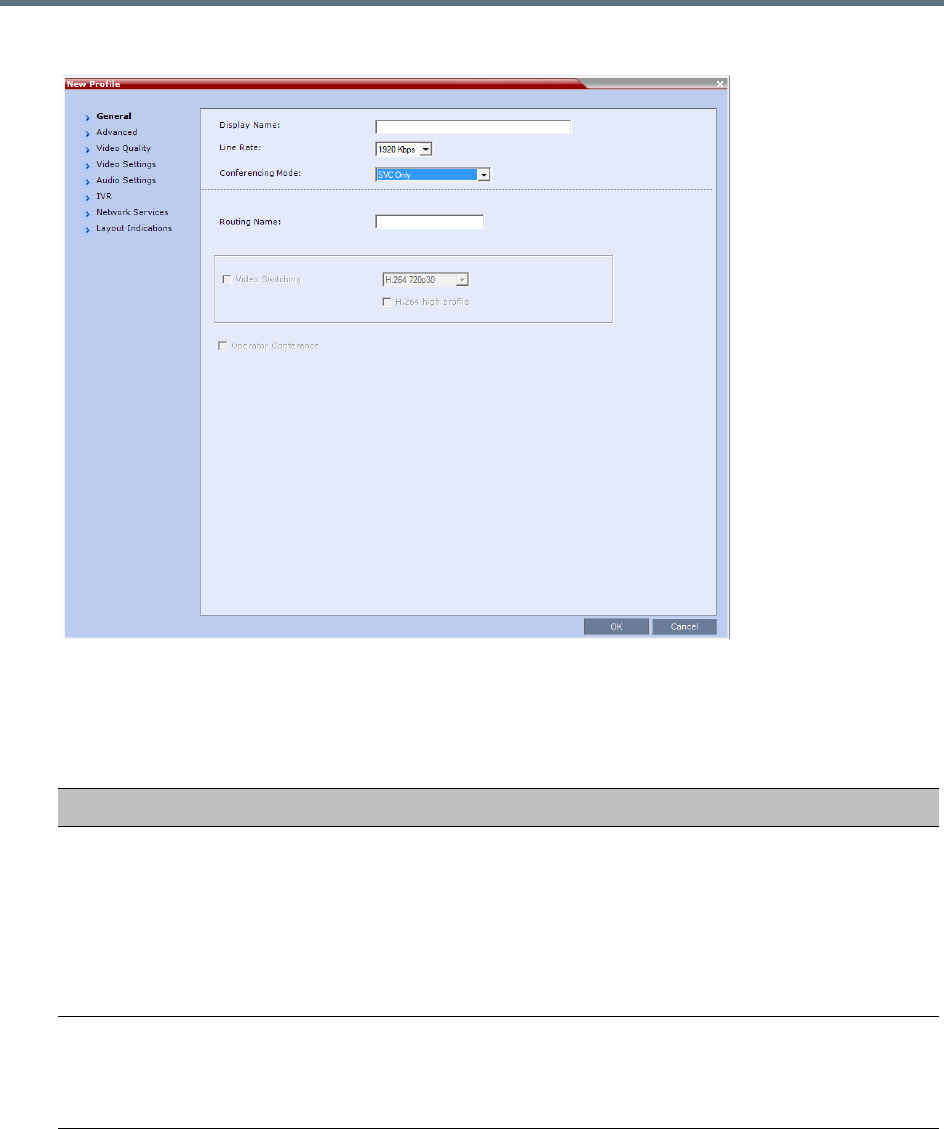
Defining SVC and Mixed CP and SVC Conference Profiles
Polycom®, Inc. 97
3Select SVC Only to define the SVC Profile.
The profile tabs and options change accordingly and only supported options are available for
selection. Unsupported options are disabled (grayed out).
4Define the Profile name and, if required, the Profile - General parameters:
New SVC Profile - General Parameters
Field/Option Description
Display Name Enter a unique Profile name, as follows:
•
English text uses ASCII encoding and can contain the most characters (length
varies according to the field).
•European and Latin text length is approximately half the length of the maximum.
•Asian text length is approximately one third of the length of the maximum.
This is the only parameter that must be defined when creating a new profile.
Note: This field is displayed in all tabs.
Line Rate Select the conference bit rate. The line rate
represents the combined video, audio
and Content rate
.
The default setting for SVC Only conferences is 1920kbps.
Note: This field is displayed in all tabs.
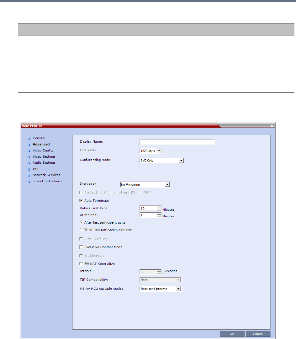
Defining SVC and Mixed CP and SVC Conference Profiles
Polycom®, Inc. 98
5Click the Advanced tab.
The New Profile – Advanced dialog box opens.
Routing Name Enter the Profile name using ASCII characters set.
You can define the Routing Name or it can be automatically generated by the
system if no Routing Name is entered as follows:
•If an all ASCII text is entered in Display Name, it is used also as the Routing
Name.
•If any combination of Unicode and ASCII text (or full Unicode text) is entered in
Display Name, the ID (such as Conference ID) is used as the Routing Name.
New SVC Profile - General Parameters
Field/Option Description

Defining SVC and Mixed CP and SVC Conference Profiles
Polycom®, Inc. 99
6Define the following supported parameters:
New SVC Profile - Advanced Parameters
Field/Option Description
Encryption Select the Encryption option for the conference:
•Encrypt All - Encryption is enabled for the conference and all conference
participants must be encrypted.
• No Encryption - Encryption is disabled for the conference.
• Encrypt when Possible - enables the negotiation between the MCU and the
endpoints and let the MCU connect the participants according to their
capabilities, where encryption is the preferred setting. For connection guidelines
see Mixing Encrypted and Non-encrypted Endpoints in one Conference.
For more information, see Packet Loss Compensation - LPR and DBA.
Auto Terminate When selected (default), the conference automatically ends when the termination
conditions are met:
• Before First Joins — No participant has connected to a conference during the
n minutes after it started. Default idle time is 10 minutes.
• At the End - After Last participant Quits — All the participants have
disconnected from the conference and the conference is idle (empty) for the
predefined time period. Default idle time is 1 minute.
• At the End - When Last Participant Remains — Only one participant is still
connected to the conference for the predefined time period (excluding the
recording link which is not considered a participant when this option is selected).
It is not recommended to select this option for SVC Conferences. Default idle
time is 1 minute.
Exclusive Content
Mode
When selected, Content broadcasting is limited to one participant preventing other
participants from interrupting the Content broadcasting while it is active. For more
details, see
FW NAT Keep Alive When selected, a FW NAT Keep Alive message is sent at an interval defined in the
field below the check box.
Interval The time in seconds between FW NAT Keep Alive messages.
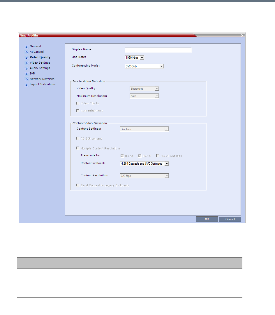
Defining SVC and Mixed CP and SVC Conference Profiles
Polycom®, Inc. 100
7Click the Video Quality tab.
The New Profile – Video Quality dialog box opens.
8In SVC Conferencing Mode, the video and Content sharing parameters cannot be modified and they
are set to the following parameters:
New SVC Profile - Video Quality Parameters
Field/Option Description
People Video Definition
Video Quality Only Sharpness is available in SVC Conferencing Mode. The MCU
sends the video stream in the resolution required by the endpoint.
Maximum Resolution Only Auto is available in SVC Conferencing Mode. The MCU sends
the video stream in the resolution required by the endpoint.

Defining SVC and Mixed CP and SVC Conference Profiles
Polycom®, Inc. 101
Content Video Definition
Content Settings Select the transmission mode for the Content channel:
•Graphics — basic mode, intended for normal graphics
• Hi-res Graphics — a higher bit rate intended for high resolution
graphic display
• Live Video — Content channel displays live video
• Customized Content Rate — manual definition of the Conference
Content Rate, mainly for cascading conferences.
Selection of a higher bit rate for the Content results in a lower bit rate
for the people channel.
Content Protocol Select the Content Protocol to be used for content sharing in Highest
Common Content Sharing Mode.
•H.263
Content is shared using the H.263 protocol.
Use this option when most of the endpoints support H.263 and
some endpoints support H.264.
• H.263 & H.264 Auto Selection
When selected, content is shared using H.263 if a mix of
H.263-supporting and H.264-supporting endpoints are connected,
or H.264 if all connected endpoints have H.264 capability.
• H.264 Cascade Optimized
All Content is shared using the H.264 content protocol and is
optimized for use in cascaded conferences.
• H.264 HD (default)
Ensures high quality Content when most endpoints support H.264
and HD resolutions.
Note: When Multiple Content Resolutions is selected, the Content
Protocol field is hidden.
For more information, see Content Protocols and Defining Content
Sharing Parameters for a Conference
New SVC Profile - Video Quality Parameters
Field/Option Description
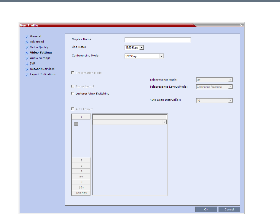
Defining SVC and Mixed CP and SVC Conference Profiles
Polycom®, Inc. 102
9Click the Video Settings tab.
In SVC conferences, each endpoint determines its own video layout and there is no conference level
layout selected. Therefore, all the Video Settings parameters are disabled.
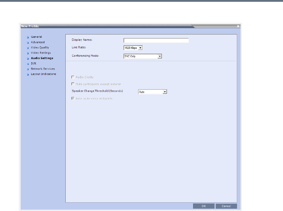
Defining SVC and Mixed CP and SVC Conference Profiles
Polycom®, Inc. 103
10 Click the Audio Settings tab.
11 If required, define the Speaker Change Threshold: Auto (Default, 3 seconds), 1.5, 3, or 5.
It indicates the amount of time a participant must speak continuously before becoming the speaker.

Defining SVC and Mixed CP and SVC Conference Profiles
Polycom®, Inc. 104
12 Click the IVR tab.

Defining SVC and Mixed CP and SVC Conference Profiles
Polycom®, Inc. 105
13 If required, set the following parameters:
The following IVR features are not supported during SVC conferences:
Roll Call
Invite Participants
Entry and Exit tones
Click & View
PCM
New SVC Profile - IVR Parameters
Field/Option Description
Conference IVR
Service
The default conference IVR Service is selected. You can select
another conference IVR Service if required.
Conference Requires
Chairperson
Select this option to allow the conference to start only when the
chairperson connects to the conference and to automatically
terminate the conference when the chairperson exits. Participants
who connect to the conference before the chairperson are placed on
Hold and hear background music (and see the Welcome video slide).
Once the conference is activated, the participants are automatically
connected to the conference.
When the check box is cleared, the conference starts when the first
participant connects to it and ends at the predefined time or according
to the Auto Terminate rules when enabled.
Terminate conference
after chairperson
leaves
Select this check box to automatically terminate the conference after
the chairperson leaves. When the chairperson leaves, the
“Chairperson Has Left” IVR message is played to all participants, at
which point the conference terminates. This way an operator does not
need to monitor a conference to know when to terminate it manually.
If there is a single chairperson in the conference who is changed to a
regular participant the conference will be terminated as if the
chairperson left. If there is more than one chairperson, then changing
one chairperson to a regular participant will not terminate the
conference. It is therefore recommended that before changing a
single chairperson to regular participant, another participant first be
changed to chairperson.
Terminate Conference After Chairperson Leaves is not supported in
cascaded environments.
On the RMX 1800, Roll Call, Entry and Exit tones are supported in SVC-only conferences.
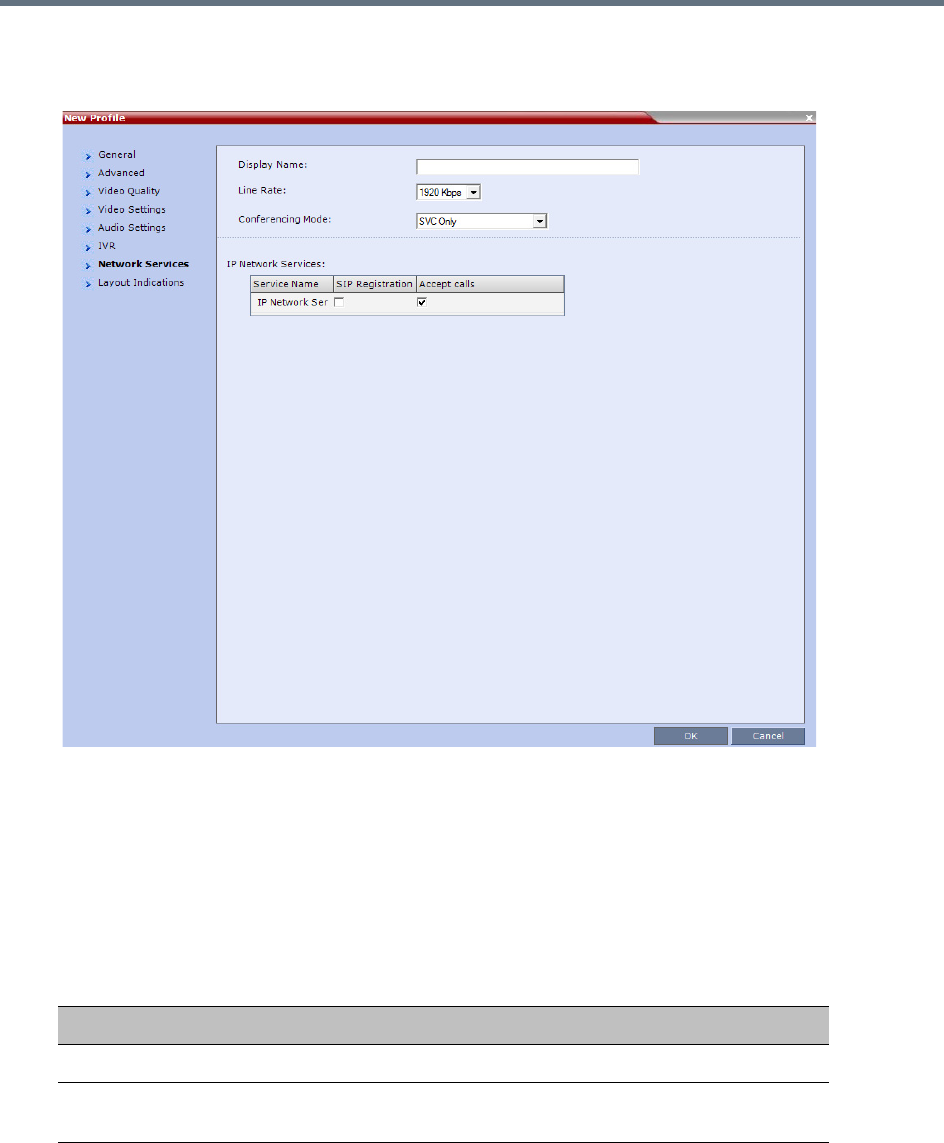
Defining SVC and Mixed CP and SVC Conference Profiles
Polycom®, Inc. 106
14 Click the Network Services tab.
The New Profile - Network Services tab opens.
Registration of conferencing entities such as ongoing conferences, Meeting Rooms, and SIP
Factories with SIP servers is done per conferencing entity. This allows better control of the number
of entities that register with each SIP server. Selective registration is enabled by assigning a
conference Profile in which registration is configured for the required conferencing entities. Assigning
a conference Profile in which registration is not configure for conferencing entities will prevent them
from registering. By default, Registration is disabled in the Conference Profile, and must be enabled
in Profiles assigned to conferencing entities that require registration.
15 Define the following parameters:
New SVC Profile - Network Services Parameters
Parameter Description
IP Network Services
Service Name This column lists all the defined Network Services, one or several
depending on the system configuration.
Defining SVC and Mixed CP and SVC Conference Profiles
Polycom®, Inc. 107
16 Click OK to complete the Profile definition.
A new Profile is created and added to the Conference Profiles list.
SIP Registration To register the conferencing entity to which this profile is assigned
with the SIP Server of the selected Network Service, click the check
box of that Network Service in this column.
When SIP registration is not enabled in the conference profile, the
Collaboration Server's registering to SIP Servers will each register
with an URL derived from its own signaling address.
Accept Calls To prevent dial in participants from connecting to a conferencing
entity when connecting via a Network Service, clear the check box of
the Network Service from which calls cannot connect to the
conference.
The Layout Indications tab is relevant only to AVC only or Mixed CP and SVC conferencing modes,
therefore though visible in SVC only conferencing mode, it is completely disabled and irrelevant.
New SVC Profile - Network Services Parameters
Parameter Description
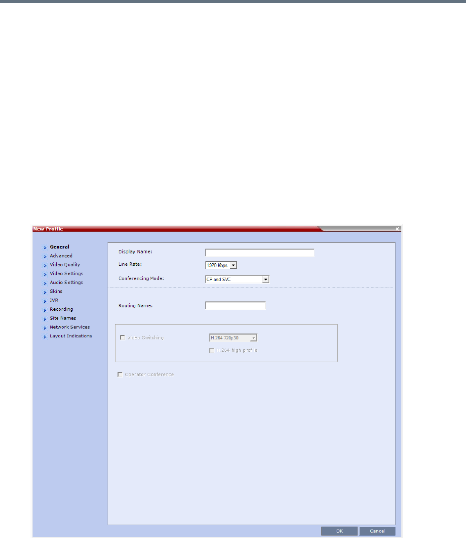
Defining SVC and Mixed CP and SVC Conference Profiles
Polycom®, Inc. 108
Defining Mixed CP and SVC Conferencing Profiles
The mixed CP and SVC Profile is based on the CP Profile with a few of the CP options disabled for
compatibility between AVC and SVC protocols and to enable the media conversion between these two
modes. The Gathering Settings and the Message Overlay options are unavailable in this Conferencing
Mode.
In a mixed CP and SVC conference, the Chairperson can be either an AVC-enabled or SVC-enabled
endpoint.
To configure a mixed AVC and SVC conference:
1In the RMX Management pane, click Conference Profiles.
2In the Conference Profiles pane, click the New Profile button.
The New Profile - General dialog box is displayed.
3In the Conferencing Mode list, select CP and SVC to define a mixed AVC and SVC conference.

Defining SVC and Mixed CP and SVC Conference Profiles
Polycom®, Inc. 109
Using the various Profile tabs, you can define the following profile parameters:
●CP and SVC Profile - Advanced parameters - these parameters are the same as for CP
conferences. For details, see New AVC CP Profile - Advanced Parameters.
●CP and SVC Profile - Video Quality parameters - to enable the sharing of video between SVC and
AVC, the common denominator parameters (in this conference, the SVC parameters) are selected
for the conference. For more details, see New SVC Profile - Video Quality Parameters.
●CP and SVC Profile - Video Settings parameters - the video layout parameters apply only to the
AVC-enabled endpoints and do not apply to SVC-enabled endpoints as the SVC endpoints generate
their own layout. Options that are not supported in SVC conferencing are disabled in this dialog box,
for example, Telepresence Mode. For more details, see New AVC CP Profile - Video Settings
Parameters.
●CP and SVC Profile - Audio Settings parameters - options that are not supported in SVC
conferencing are disabled in this dialog box. For more details, see New AVC CP Profile - Audio
Settings Parameters.
●CP and SVC Profile - Skins parameters - the display of a video skin applies only to the AVC-enabled
endpoints and do not apply to SVC-enabled endpoints as the SVC endpoints generate their own
layout.
●CP and SVC Profile - IVR parameters - to enable the same IVR behavior and DTMF usage for SVC
and AVC, the common denominator parameters (in this conference, the SVC parameters) are
selected for the conference. For more details, see New SVC Profile - IVR Parameters.
●CP and SVC Profile - Recording parameters - these parameters are the same as for CP
conferences as the recording is done in AVC format. For details, see New AVC CP Profile - Recording
Parameters.
●CP and SVC Profile - Site Names parameters - these parameters are the same as for CP
conferences as they apply the AVC-enabled endpoints. SVC-enabled endpoints generate the site
name display independent of the MCU. For details, see New AVC CP Profile - Site Names
Parameters.
●CP and SVC Profile - Network Services parameters - these parameters are the same as for CP and
SVC conferences. For details, see New AVC CP Profile - Network Services Parameters.
●CP and SVC Profile - Layout Indications parameters - these parameters are the same as for CP
conferences. For details, see New AVC CP Profile - Layout Indications Parameters.

Polycom®, Inc. 110
Video Protocols and Resolution
Configuration for CP Conferencing
Video Resolutions in AVC CP Conferencing
The RealPresence Collaboration Server always attempts to connect to endpoints at the highest line rate
defined for the conference. If the connection cannot be established using the conference line rate, the
Collaboration Server attempts to connect at the next highest line rate at its highest supported resolution.
Depending on the line rate, the Collaboration Server sends video at the best possible resolution supported
by the endpoint regardless of the resolution received from the endpoint.
The video resolution is also defined by the Video Quality settings in the Profile.
●Motion, when selected, results in lower video resolution at higher frame rates (30 fps to 60 fps).
●Sharpness, when selected, results in higher video resolution at lower frame rate (30 fps and lower).
However, it can also be sent in 1080p 60fps.
The combination of frame rate and resolution affects the number of video resources required on the MCU
to support the call.
The following resolutions are supported:
Video Display with CIF, SD and HD Video Connections
Although any combination of CIF, SD and HD connections is supported in all CP conferences, the following
rules apply:
For a description of resolutions for SVC Conferencing Mode see Defining SVC Conference Profiles.
Supported Resolutions
Resolution Name Resolution in Pixels Frames per Second Symmetric/Asymmetric
CIF 352 x 288 30, 60 Symmetric
SD 720 x 576 30, 60 Symmetric
HD 720p 1280 x 720 30, 60 Symmetric
HD 1080p 1920 x 1080 30 Symmetric
HD 1080p 1920 x 1080 60 Symmetric in Motion,
Asymmetric in Sharpness

Video Protocols and Resolution Configuration for CP Conferencing
Polycom®, Inc. 111
●In a 1X1 Video Layout:
SD: If the speaker transmits CIF, the MCU will send CIF to all participants, including the SD
participants. In any other layout the MCU will transmit to each participant at the participant’s
sending resolution.
HD: The MCU transmits speaker resolution (including input from HD participants) at up to SD
resolution. If 1x1 is the requested layout for the entire duration of the conference, set the
conference to HD Video Switching mode.
●In asymmetrical Video Layouts:
SD: A participant in the large frame that sends CIF is displayed in CIF.
HD: Where participants’ video windows are different sizes, the Collaboration Server transmits HD
and receives SD or lower resolutions.
●In panoramic Video Layouts:
SD: Participants that send CIF also receive CIF.
HD: the Collaboration Server transmits HD and receives SD or lower resolutions, the
Collaboration Server scales images from SD to HD resolution.
H.264 High Profile Support in CP Conferences
The H.264 High Profile is a new addition to the H.264 video protocol suite. It uses the most efficient video
data compression algorithms to even further reduce bandwidth requirements for video data streams.
Video quality is maintained at bit rates that are up to 50% lower than previously required. For example, a
512Kbps call will have the video quality of a 1Mbps HD call while a 1Mbps HD call has higher video quality
at the same (1Mbps) bit rate.
H.264 High Profile Guidelines
●H.264 High Profile is supported in H.323, and SIP and ISDN networking environments.
●H.264 High Profile is supported in all conference modes, all bit rates, video resolutions and layouts.
●H.264 High Profile is the first protocol declared by the Collaboration Server, to ensure that endpoints
that support the protocol will connect using it.
Setting minimum bit rate thresholds that are lower than the default may affect the video quality of
endpoints that do not support the H.264 High Profile.
●For monitoring purposes, the Collaboration Server and endpoint H.264 High Profile capability is listed
in the Participant Properties - H.245 and SDP tabs for H.323 participants and SIP participants
respectively.
For more information see Monitoring IP Participants.
●H.264 High Profile is not supported:
For Content Sharing with MPMx cards
With Video Preview
H.264 High-Profile should be used when all or most endpoints support it.

Video Protocols and Resolution Configuration for CP Conferencing
Polycom®, Inc. 112
HD1080p60 Resolution Guidelines
HD1080p60 resolution is supported in Continuous Presence (CP) mode:
●With MPMx media cards:
Asymmetrically: The Collaboration Server receives HD720p60 and sends HD1080p60.
In both Video Quality modes (Motion or Sharpness).
With line rates between 2Mbps and up to 4 Mbps (the maximum line rate available for CP
conferences).
●With MPMRx media cards / RMX1800:
Symmetrically: The Collaboration Server receives and sends HD1080p60.
With Video Quality mode set to Motion.
For H.323 and SIP participants.
At line rates up to 4Mbps.
RMX1800-0 only supports HD1080p60 symmetric video when Video Quality is set as Motion in
the conference Profile.
HD1080p60 resolution is supported in Video Switching (VSW) mode:
At bit rates of up to 6Mbps.
HD1080p60 is supported symmetrically: The RMX receives and sends HD1080p60.
HD1080p60 resolution is not supported:
For ISDN participants.
With RTV video protocol.
HD1080p60 resolution is not supported symmetrically:
In 1X1 layouts, including 1X1 layouts in Telepresence Mode. Instead, the Collaboration Server
transmits the current speaker endpoint’s video resolution and frames per second.
In TIP environments.
In Telepresence environments the RMX receives HD720p60 and sends HD1080p60 to all endpoints except
for those with 1x1 Video Layouts, which receive the same resolution and frame rate from the RMX as they
send. TIP endpoints are not supported.
PAL endpoints are supported at a frame rate of 50 fps.
Video Protocols and Resolution Configuration for CP Conferencing
Polycom®, Inc. 113
CP Conferencing with H.263 4CIF
The video resolution of 4CIF in H.263 endpoints is only supported for conferences in which the video quality
is set to sharpness and for line rates of 384 Kbps to 1920 Kbps as shown in the following table.
The Collaboration Server Web Client supports monitoring of H.263 4CIF information. The H.245 or SDP tab
includes the additional information.
The creation of a new H.263 4CIF slide is supported in the IVR Service in addition to the current H.263 IVR
slide. If users utilize the default Polycom slides that are delivered with the Collaboration Server, the slide’s
resolution will be as defined in the profile, i.e. SD, HD, CIF, etc.
For more information see Accessing the Resolution Configuration Dialog Box.
H.263 4CIF Guidelines
●H.263 4CIF is supported with H.323, and SIP and ISDN connection endpoints.
●H.263 4CIF is supported in CP mode only.
●Click&View is supported in H.263 4CIF.
●AES encryption is supported with H.263 4CIF.
●Recording of H.263 4CIF conferences is supported by the RealPresence Capture Server or RSS
4000 system and other devices.
●All video layouts are supported in H.263 4CIF, except 1x1 layout. In a 1x1 layout, the resolution will
be CIF.
●H.239 is supported in H.263 4CIF and is based on the same bandwidth decision matrix as for HD.
The CP Resolution Decision Matrix
All the CP resolution options and settings are based on a decision matrix which matches video resolutions
to connection line rates, with the aim of providing the best balance between resource usage and video
quality at any given line rate.
Video Quality vs. Line Rate
Endpoint
Line Rate Kbps
Video Quality
Motion Sharpness
Resolution Frame Rate Resolution Frame Rate
128 QCIF 30 CIF 30
256 CIF 30 CIF 30
384 - 1920+ CIF 30 4CIF 15
128 CIF 30
256 CIF 30
384 - 1920+ 4CIF 15

Video Protocols and Resolution Configuration for CP Conferencing
Polycom®, Inc. 114
The following factors affect the decision matrices:
●The Media card(s) installed in the system affect the number of video resources used for each video
resolution and frame rate, the supported video protocols and the maximum resolution that can be
used by the Collaboration Server.
●The used video protocol: H.264 base Profile or H.264 High Profile. The H.264 High Profile maintains
the Video quality at bit rates that are up to 50% lower than previously required. For example, a 512
kbps call will have the video quality of a 1Mbps HD call while a 1Mbps HD call has higher video quality
at the same (1Mbps) bit rate.
●A different decision matrix is used for Motion and Sharpness as the quality requirements are different.
The system is shipped with three pre-defined settings of the decision matrix for H.264 Base Profile and three
pre-defined settings of the decision matrix for H.264 High Profile with Motion and Sharpness video quality
for each of the following resource management schemes:
●Resource-Quality Balanced (default)
A balance between video quality and resource usage. This is the only available resolution
configuration in version 6.0.x and earlier.
●Resource Optimized
System resource usage is optimized by allowing high resolution connections only at high line rates
and may result in lower video resolutions (in comparison to other resolution configurations) for some
line rates. This option allows to save MCU resources and increase the number of participant
connections.
●Video Quality Optimized
Video is optimized through higher resolution connections at lower line rates increasing the resource
usage at lower line rates. This may decrease the number of participant connections.
Video Resource Usage
Video resource usage is dependent on the participant’s line rate, resolution and Video Quality settings.

Video Protocols and Resolution Configuration for CP Conferencing
Polycom®, Inc. 115
Default Minimum Threshold Line Rates and Resource
Usage Summary
The following Table summarizes the Default Minimum Threshold Line Rates and Video Resource usage for
each of the pre-defined optimization settings for each Resolution, H.264 Profile, Video Quality setting
(Sharpness and Motion) for MPMx/MPMRx Card Configuration Modes.
Default Minimum Threshold Line Rates and Video Resource Usage
Resolution Profile
Optimization Mode
Balanced Resource Video Quality
Sharpness Motion Sharpness Motion Sharpness Motion
HD1080p60 Default
kbps
High 2560* 2560 3584* 3584 2048* 1728
Base 3584* 3584 4096* 4096 3584* 3072
HD1080p30 Default
kbps
High 1536 2560 1024
Base 2048 2560 1728
HD720p60 Default
kbps
High 1280 2560 832
Base 1920 1920 1280
HD720p30 Default
kbps
High 832 1280 512
Base 1024 1536 832
SD 60 Default
kbps
High 768 1024 512
Base 1024 1024 768
SD 30 Default
kbps
High 256 384 256
Base 256 384 256
CIF 60 Default
kbps
High 256 384 256
Base 384 384 256
CIF 30 Default
kbps
High 64646464 6464
Base 64 64 64 64 64 64
* Applicable to Collaboration Server (RMX) 1800 and MPMRx only
•The table above lists resource consumption for H.264.
•For H.263 with MPMx cards:
CIF resolution consumes 1.5 resources.
4CIF resolution consumes 3 resources.
Video Protocols and Resolution Configuration for CP Conferencing
Polycom®, Inc. 116
Resolution Configuration for CP Conferences
The Resolution Configuration dialog box enables you to override the default video resolution decision
matrix, effectively creating your own decision matrix. The minimum threshold line rates at which endpoints
are connected at the various video resolutions can be optimized by adjusting the resolution sliders.
System resource usage is also affected by the Resolution Configuration settings.
For more information see Video Resource Usage and Default Minimum Threshold Line Rates and Resource
Usage Summary.
Guidelines
●Resolution Slider settings affect all Continuous Presence (CP) conferences running on the
Collaboration Server. Video Switched conferences are not affected.
●A system restart is not needed after changing the Resolution Slider settings.
●Resolution Slider settings cannot be changed if there are ongoing conferences running on the
Collaboration Server. The displayed sliders and the resolutions change according the MCU type.
Modifying the Resolution Configuration
The Resolution Configuration dialog box is accessed by clicking Setup > Resolution Configuration in
the Collaboration Server Setup menu.
Clicking the Detailed Configuration button toggles the display of the Detailed Configuration pane, which
displays sliders for modifying minimum connection threshold line rates for endpoints that support H.264
Base Profile or High Profile. The Detailed Configuration pane can also be opened by clicking the Manual
radio button in the Resolution Configuration pane.
Sharpness and Motion settings are accessed by clicking the Sharpness and Motion tabs when the
Detailed Configuration is open.
Maximum Negotiated Line Rate for Resolutions
Line Rate Resolution
Up to 1M CIF60, SD30 and below
Up to 4M SD60, HD720p30
Up to 6M HD720p60, HD1080p30, HD1080p60
On the RealPresence Collaboration Server (RMX) 1500 MPMx-Q assembly, the use of HD with
Continuous Presence requires an additional license. In the Resource Report and Resolution
Configuration panes, HD settings are displayed but are not enabled and if HD is selected the system
will enable SD by default.
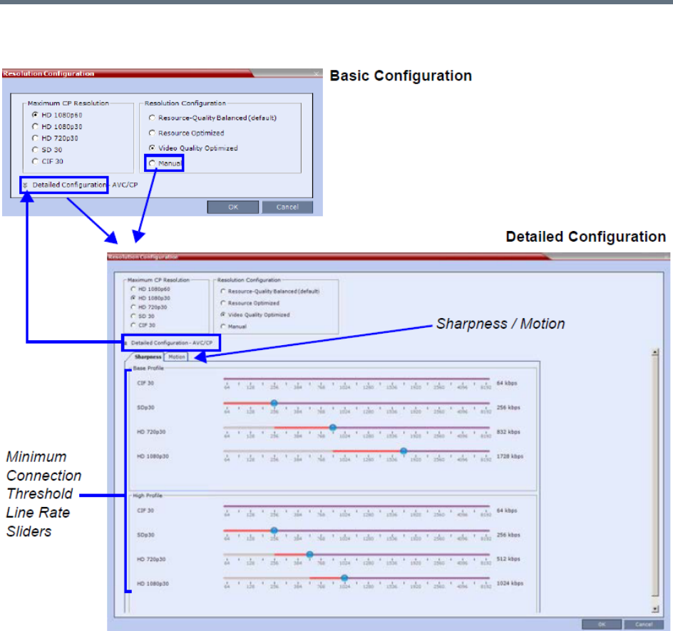
Video Protocols and Resolution Configuration for CP Conferencing
Polycom®, Inc. 117
Resolution Configuration
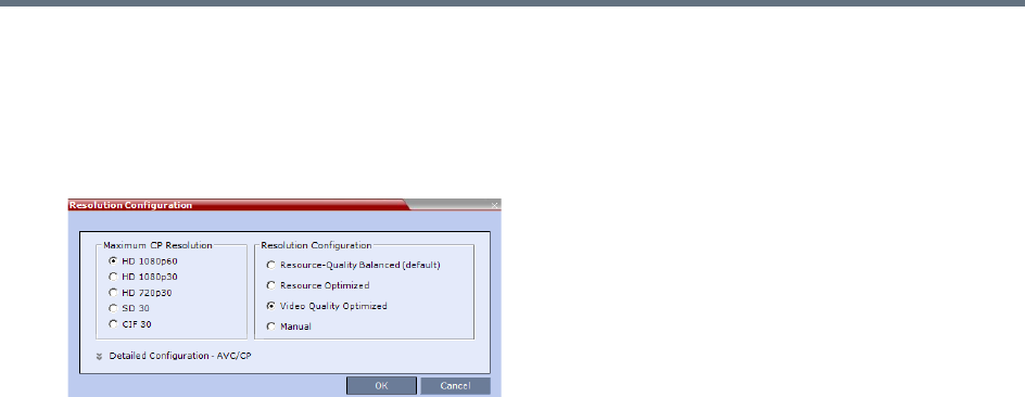
Video Protocols and Resolution Configuration for CP Conferencing
Polycom®, Inc. 118
Resolution Configuration - Basic
The Resolution Configuration basic dialog box contains the following panes:
●Max CP Resolution Pane
●Resolution Configuration Pane
Maximum CP Resolution Pane
The Collaboration Server can be set to one of the following Maximum CP Resolutions:
●HD 1080p60
●HD 1080p30
●HD 720p30
●SD 30
●CIF 30
Limiting Maximum Resolution
Before a selection is made in this pane, the Maximum CP Resolution of the system is determined by the
MAX_CP_RESOLUTION System Flag.
The MAX_CP_RESOLUTION flag value is applied to the system during First Time Power-on and after a
system upgrade.
The default flag value is HD1080 setting the Maximum CP Resolution value in the Resolution
Configuration dialog box to 1080p60.
All subsequent changes to the Maximum CP Resolution of the system are made by selections in this pane.
The Maximum Resolution can further be limited per conference or per participant endpoint.
The Maximum Conference Resolution, can be limited via the Profile - Video Quality dialog box. For more
information see New AVC CP Profile - Video Quality Parameters and New SVC Profile - Video Quality
Parameters.
The Maximum Resolution can further be limited per participant endpoint via the Participant - Properties
dialog box. For more information see New Participant - Advanced.
Resolution Configuration Pane
The user can select from 3 pre-defined Resolution Configurations or select a manual Resolution Slider
adjustment mode. The pre-defined settings can be accepted without modification or be used as the basis
for manual fine tuning of resolution settings by the administrator.
The Manual radio button is automatically selected if any changes are made to the Resolution Sliders.

Video Protocols and Resolution Configuration for CP Conferencing
Polycom®, Inc. 119
The Resolution Configurations are:
●Resource-Quality Balanced (default)
A balance between the optimized video quality and optimized resource usage.
The Balanced settings are described in the section: Default Minimum Threshold Line Rates and
Resource Usage Summary.
●Resource Optimized
System resource usage is optimized by allowing high resolution connections only at high line rates
and may result in lower video resolutions (in comparison to other resolution configurations) for some
line rates.
The Resource Optimized settings are described in the section: Default Minimum Threshold Line
Rates and Resource Usage Summary.
●Video Quality Optimized
Video is optimized through higher resolution connections at lower line rates increasing the resource
usage at lower line rates. This may decrease the number of participant connections.
The Video Quality Optimized settings are described in the section: Default Minimum Threshold Line
Rates and Resource Usage Summary.
●Manual
Manually adjusting the sliders to accommodate local conferencing requirements.
Resolution Configuration - Detailed
The Resolution Configuration -Detailed dialog box contains the following panes:
●Sharpness Resolution sliders
●Motion Resolution sliders
Sharpness and Motion
Sharpness and Motion are Video Quality settings that are selected per conference and are defined in the
conference Profile. A conference with Sharpness selected in its Profile uses the Sharpness settings of the
Use this option:
•When the priority is to maintain a balance between resource usage and video quality.
•When it is necessary to maintain backward compatibility with previous versions.
•When working with Polycom DMA/RealPresence Resource Manager.
Use this option when the priority is to save MCU resources and increase the number of participant
connections.
fr
Use this option when the priority is to use higher video resolutions while decreasing the number of
participant connections.

Video Protocols and Resolution Configuration for CP Conferencing
Polycom®, Inc. 120
Resolution Configuration and a conference with Motion selected in its Profile uses the Motion settings of the
Resolution Configuration dialog box.
The Sharpness and Motion tabs in the Resolution Configuration dialog box allow you to view and modify
Resolution Configuration settings for conferences with either Video Quality setting.
The Sharpness and Motion tabs include separate settings for Base Profile and High Profile as the
Collaboration Server uses two decision matrices (Base Profile, High Profile) to enable endpoints to connect
according to their capabilities.
H.264 High Profile allows higher quality video to be transmitted at lower bit rates. However, setting minimum
bit rate thresholds that are lower than the default may affect the video quality of endpoints that do not
support the H.264 High Profile.
Resolution Configuration Sliders
The Detailed Configuration dialog box allows you to configure minimum connection threshold bit rates for
endpoints that support H.264 High Profile and those that do not support H.264 High Profile by using the
following slider panes:
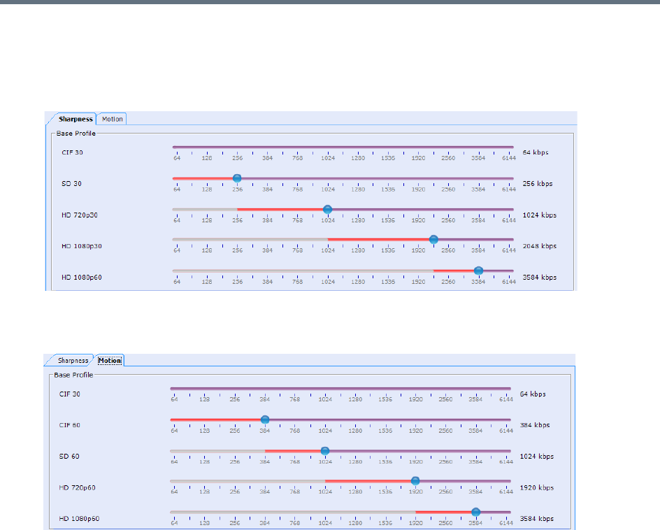
Video Protocols and Resolution Configuration for CP Conferencing
Polycom®, Inc. 121
●Base Profile - Endpoints that do not support H.264 High Profile connect at these minimum threshold
bit rates.
In Sharpness mode
In Motion mode
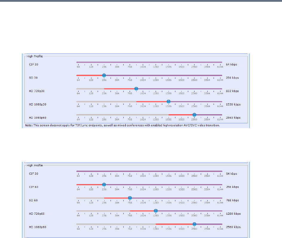
Video Protocols and Resolution Configuration for CP Conferencing
Polycom®, Inc. 122
●High Profile - Endpoints that support H.264 High Profile connect at these minimum threshold bit
rates.
In Sharpness mode
In Motion mode
Although the default minimum threshold bit rates provide acceptable video quality, the use of higher bit rates
usually results in better video quality but will require more resources.
The Base Profile and High Profile sliders operate in the same manner in Sharpness and in Motion.
Video Resource usage is affected by the Resolution Configuration settings. The lower the line rate threshold
set for a certain resolution the more resources will be used to connect that participant (as a higher resolution
will be used).
Modifying the Resolution Configuration in MPMx Card Configuration
Mode
Moving the slider of a certain resolution to the left reduces the line rate threshold required for the endpoints
to connect using that resolution (resulting in higher video quality, more video resources). Moving the slider
to the right, increases the line rate required for the endpoint to connect using that resolution (resulting in
lower video quality, less video resources).
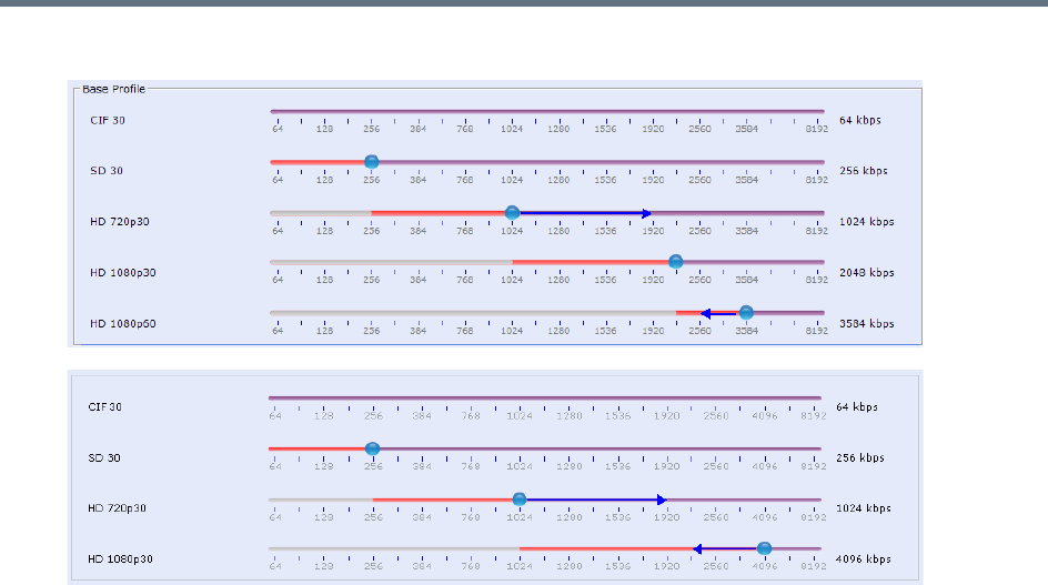
Video Protocols and Resolution Configuration for CP Conferencing
Polycom®, Inc. 123
The following example demonstrate the usage of the sliders.
●Moving the HD720p30 resolution slider from 1024kbps to 1920kbps increases the minimum
connection threshold line rate for that resolution. Endpoints connecting at line rates between
1024kbps and 1920kbps that would have connected at HD 720p30 resolution will instead connect at
SD 30 resolution. Each of the affected endpoints will connect at lower resolution but will use less
video resources.
●Moving the HD1080p30 resolution slider from 4096kbps to 2560kbps decreases the minimum
connection threshold line rate for that resolution. Endpoints connecting at line rates between
2560kbps and 4096kbps that would have connected at HD 720p30 resolution will instead connect at
HD 1080p30 resolution. Each of the affected endpoints will connect at higher resolution but will use
more video resources.
●Moving the HD1080p60 resolution slider from 3584kbps to 2560kbps decreases the minimum
connection threshold line rate for that resolution. Endpoints connecting at line rates between
2560kbps and 4096kbps that would have connected at HD 1080p30 resolution will instead connect
at HD 1080p60 resolution. Each of the affected endpoints will connect at higher resolution but will use
more video resources.
Flag Settings
Setting the Maximum CP Resolution for Conferencing
The MAX_CP_RESOLUTION flag value is applied to the system during First-time Power-up and after a
system upgrade. The default value is HD1080.
All subsequent changes to the Maximum CP Resolution of the system are made by selections in the Max
CP Resolution pane of the Resolution Configuration dialog box.

Video Protocols and Resolution Configuration for CP Conferencing
Polycom®, Inc. 124
The Maximum CP Resolution of the Collaboration Server can be set to one of the following resolutions:
●HD 1080p60
●HD 1080p30
●HD 720p30
●SD 30
●CIF 30
Minimum Frame Rate Threshold for SD Resolution
The MINIMUM_FRAME_RATE_THRESHOLD_FOR_SD System Flag can be added and set to prevent low
quality, low frame rate video from being sent to endpoints by ensuring that an SD channel is not opened at
frame rates below the specified value. For more information see Modifying System Flags.
Additional Video Resolutions
The following higher video quality resolutions are available:
MPMRx Supported Resolutions
Resolution Name Resolution in Pixels Frames per Second
CIF 352 x 288 50
WCIF 512 x 288 50
WSD 848 x 480 50
W4CIF 1024 x 576 30
HD 720p 1280 x 720 60
HD 1080p 1920 x 1080 30
HD 1080p 1920 x 1080 60
The video resolution transmitted to any endpoint is determined by the endpoint’s capabilities, the
conference line rate, the Conference Profile’s Motion and Sharpness settings and the Collaboration
Server’s Card Configuration Mode (MPMx or MPMRx).

Video Protocols and Resolution Configuration for CP Conferencing
Polycom®, Inc. 125
w448p Resolution
For improved interoperability with Tandberg MXP 990/3000 endpoints, the appropriate System Flag settings
will force the Collaboration Server to send w448p (768x448 pixels) at 25fps as a replacement resolution for
WSD15 (848x480) and SD15 (720x576 pixels).
Guidelines
●The w448p resolution is supported:
In CP mode.
At conference line rates of 384kbps and 512kbps.
With H.323, SIP, and ISDN endpoints.
H.323 endpoints must identify themselves as Tandberg MXP during capabilities exchange.
In all Video Layouts.
In 1x1 Layout:
When Video Clarity is Off, the Collaboration Server transmits the same resolution as it
receives.
When Video Clarity is On, the Collaboration Server changes the transmitted resolution to
w448p.
For more information see Video Clarity™.
●Resource consumption for the w448p resolution is the same as for SD and WSD resolutions.
The following table lists the video outputs from the Collaboration Server to the Tandberg Endpoints for both
16:9 Aspect Ratio when the w448p resolution is enabled.
The following table list the video outputs from the Collaboration Server to the Tandberg Endpoints for 4:3
Aspect Ratio when the w448p resolution is enabled.
Video Output to Tandberg Endpoints- Aspect Ratio 16:9
Network
Environment
Video Quality Line
Rate
Kbps
Resolution
Frame
Rate
fps
Resolutio
n
Frame
Rate fps
Tandberg
Collaboration
Server
Tandberg to
Collaboration Server
Collaboration Server
to Tandberg
H.323
SIP
Motion Sharpness 384 512x288 30 768x448 25
512 768x448 30 768x448 25
H.323
SIP
Sharpness
*
Sharpness 384 1024x576 15 768x448 25
512 1024x576 15 768x448 25
* It is recommend to set the endpoint to Motion to ensure the transmission of the higher frame rates of 25fps/30fps
to the Collaboration Server.
Video Protocols and Resolution Configuration for CP Conferencing
Polycom®, Inc. 126
Content
Sharing and receiving Content is supported.
Bandwidth allocated to the Content channel during Content sharing may cause the video resolution to be
decreased as from w448p to w288p.
When Content sharing stops and the full bandwidth becomes available, video resumes at the previous
w448p resolution.
For more information see the Additional Conferencing Information.
Packet Loss Compensation
If there is Packet Loss in the network and Dynamic Bandwidth Allocation (DBA) is activated, allocating
bandwidth for Lost Packet Recovery, video resolution decreases from w448p to w288p.
When Packet Loss ceases and DBA no longer needs to allocate bandwidth for Lost Packet Recovery, the
full bandwidth becomes available and video resumes at the previous w448p resolution.
For more information see the Packet Loss Compensation - LPR and DBA.
Enabling Support of the w448p Resolution
w448p resolution support for Tandberg endpoints requires setting of the following entities:
●Tandberg endpoint
●Collaboration Server flags
●Collaboration Server Conference Profile
Video Output to Tandberg Endpoints - Aspect Ratio 4:3
Network
Environment
Video Quality Line
Rate
Kbps
Resolution
Frame
Rate
fps Resolution
Frame
Rate
fps
Tandberg
Collaboration
Server
Tandberg to
Collaboration Server
Collaboration Server
to Tandberg
H.323
SIP
ISDN
Motion Sharpness 384 576x448 ‡25 768x448 25
512 576x448 ‡ 25 768x448 25
H.323
SIP
ISDN
Sharpness*Sharpness 384 4CIF 15 768x448 25
512 4CIF 15 768x448 25
* It is recommend to set the endpoint to Motion to ensure the transmission of the higher frame rates of 25fps/30fps
to the Collaboration Server.
‡ MXP 990/3000 endpoints transmit 576x448 pixels. Other MXP endpoints may transmit other
resolutions eg. CIF.

Video Protocols and Resolution Configuration for CP Conferencing
Polycom®, Inc. 127
Collaboration Server System Flag Settings
On the Collaboration Server, the Video Quality field in the New Profile - Video Quality dialog box must be
set to Sharpness.
For more information see Defining New Profiles.
Additional Intermediate Video Resolutions
Two higher quality, intermediate video resolutions replace the transmission of CIF (352 x 288 pixels) or SIF
(352 x 240 pixels) resolutions to endpoints that have capabilities between:
●CIF (352 x 288 pixels) and 4CIF (704 x 576 pixels) – the resolution transmitted to these endpoints is
432 x 336 pixels.
●SIF (352 x 240 pixels) and 4SIF (704 x 480 pixels) – the resolution transmitted to these endpoints is
480 x 352 pixels.
The frame rates (depending on the endpoint’s capability) for both intermediate resolutions are 25 or 30 fps.

Polycom®, Inc. 128
Sharing Content During Conferences
Content such as graphics, presentations, documents, or live video can be shared with conference
participants.
Content sharing architecture is comprised of various aspects:
●Content Control Protocols - H.239 (for H.323 / ISDN), BFCP (for SIP), or People+Content
(Polycom’s protocol used for CP conferences prior to H.239 creation)
●Content Media Protocols - H.263 (AVC only), H.264 (all conferencing modes), or TIP (Cicso’s
proprietary protocol for TelePresence endpoints).
●Content Transmission Methods - Content Video Switching and Multiple Content Resolutions.
●Content Settings - Graphics, Hi-res Graphics, Live Video, or Customized Content Rate.
Content Control Protocols
Endpoints wishing to share content, request the Content Token from the MCU (in cascaded environments,
the Master MCU). The MCU uses the control protocol to grant the Content Token to the requesting endpoint
(unless in Exclusive Content Mode).
Guidelines for Controlling Content
●Only the Content Token owner may send content.
●Content Token ownership is valid until:
A new endpoint requests token ownership (unless in Exclusive Content Mode).
The owner relinquishes it.
The Content Token owner endpoint disconnects from the conference.
It is canceled by the MCU user.
Supported Content Control Protocols
Polycom supports content sharing using one of the following content control protocols:
●H.239 - For H.323 or ISDN participants
●BFCP - For SIP participants (over TCP or UDP)
●TIP Auto-Collaboration (CISCO TIP participants) - TIP Auto-Collaboration for H.264 content sharing
(see TIP Compatibility - Prefer TIP)
●People+Content - Polycom’s proprietary content control protocol; for H.323 and ISDN participants
Endpoints supporting the content control protocols above can share content within the same conference.
Endpoints without the content capabilities matching the conference content sharing
requirements, can connect to the conference but cannot share or view content in the
content channel. Depending on Legacy definitions, they can view content in the people
video layout (see Sending Content to Legacy Endpoints).

Sharing Content During Conferences
Polycom®, Inc. 129
Content Sharing Using H.239 Protocol
This protocol is used by H.323 and ISDN endpoints.
The H.239 protocol allows compliant endpoints to share content stream simultaneously with video.
Cascaded links declare H.239 capabilities, and are supported in Star and MIH cascading topologies. For
more details, see Cascading Conferences - H.239-enabled MIH Topology.
Content sharing is supported only during conferencing (not while in Entry Queue).
Content Sharing Using BFCP Protocol
This protocol is used by SIP endpoints.
The MCU supports BFCP over either TCP or UDP, which enables the MCU to share content with both SIP
client types.
Guidelines for Using SIP BFCP Content
For SIP clients supporting BFCP/TCP or BFCP/UDP:
●BFCP content is not supported over SIP links (in Gateway and cascading scenarios). Therefore, in
cascading environment, the cascaded link must be defined as H.323 for content to be shared.
●BFCP/UDP is supported in both IPv4 and IPv6 addressing modes. BFCP/TCP is supported only in
IPv4 addressing mode.
●Note that Lync endpoints, though considered as SIP endpoints, do not use BFCP to share content,
and use a Microsoft proprietary protocol for that purpose. There are two options to bypass that
limitation:
Polycom CSS plug-in (see Content Sharing via Polycom CSS Plug-in for Microsoft Lync Clients).
This is the preferred option, and is used whenever the CSS plug-in is currently used.
Treating Lync endpoints as Legacy, thus viewing content via the people video layout (see Sending
Content to Legacy Endpoints).
●BFCP utilizes an unsecured channel (port 60002/TCP) even when SIP TLS is enabled. If security is
of higher priority than SIP content sharing, SIP/BFCP can be disabled by manually adding the
ENABLE_SIP_PEOPLE_ PLUS_CONTENT system flag, and setting its value to NO.
●SIP and BFCP capabilities are by default declared to all endpoints.
Capabilities declaration is controlled by the ENABLE_SIP_PPC_FOR_ALL_USER_AGENT system
flag, whose default value is YES, meaning BFCP capability is declared to all vendors’ endpoints.
When set to NO, the MCU declares SIP over BFCP capabilities only to Polycom and Avaya
endpoints. Note that a SIP proxy might remove the agent information, thus preventing the capability
declaration to Polycom and Avaya endpoints as well.
●Set ENABLE_FLOW_CONTROL_REINVITE system flag to NO when SIP BFCP is enabled.
●If the system flags mentioned above do not exist in the system, they must be manually added (see
Modifying System Flags).
Note that since TIP compatible conferences (see TIP Compatibility - Prefer TIP) use H.264 as
content media protocol, endpoints supporting only H.263 are considered Legacy content endpoints
(see Sending Content to Legacy Endpoints), regardless of the control protocol they are using.
Sharing Content During Conferences
Polycom®, Inc. 130
●Due to UC-APL requirement, BFCP over TCP is not supported in Ultra Secure Mode (Collaboration
Server 1500/1800/2000/4000).
Content Sharing via Polycom CSS Plug-in for Microsoft Lync Clients
From version 8.1, Polycom CSS (Content Sharing Suite) plug-in for Lync clients allows Lync clients to
receive and send content via SIP BFCP, without having to use the people video layout.
The CSS plug-in invokes a separate call for content with or without video. This call may be invoked per a
Lync client.
Microsoft Lync is not supported by Collaboration Server (RMX) 1800-0.
Dial-out System Flags
For SIP dial-out clients supporting both TCP and UDP, the preferred protocol is BFCP/UDP. However, this
preference can be modified, by adding the SIP_BFCP_DIAL_OUT_MODE system flag and modifying its
value to TCP (see ).
The Collaboration Server’s content sharing, as determined by the system flags settings and SIP client
capabilities, is summarized in the following table:
BFCP support in dial-in Connections
●The MCU shares content with dial-in SIP clients according to their preferred BFCP protocol.
●SIP clients connected as audio-only cannot share content.
Content Sharing Using People+Content Protocol
People+Content utilizes a different content control protocol, and is Polycom’s proprietary protocol used prior
to H.239. This protocol is supported in CP conferences, and is applicable for H.323 and ISDN endpoints.
Guidelines for Content Sharing Using People+Content Protocol
●If an endpoint supports both H.239 and People+Content protocols, H.239 is selected as the preferred
communication protocol.
●H.263 and H.263 and H.264 Auto-selection are the only supported content media protocols usage
modes (see MCU Usage Modes of Content Protocols).
●People+Content is enabled by default. It can be disabled for all conferences and endpoints by
manually adding the ENABLE_EPC System Flag, and setting its value to NO (default value is YES).
System Flag - SIP_BFCP_DIAL_OUT_MODE
Flag Value
SIP Client: BFCP Support
UDP TCP UDP and TCP
AUTO (Default) BFCP/UDP selected as
content sharing protocol
BFCP/TCP selected as
content sharing protocol
BFCP/UDP selected as
content sharing protocol
UDP Cannot share content
TCP Cannot share content BFCP/TCP selected as content sharing protocol

Sharing Content During Conferences
Polycom®, Inc. 131
●Endpoints supporting People+Content (for example, FX endpoints) may require a different signaling
protocol. For these endpoints, manually add the System Flag CS_ENABLE_EPC, and set its value
to YES (default value is NO).
Content Media Protocols
The RealPresence Collaboration Server transmits content using the following content media protocols:
●H.263 (Annex T) - Base profile only.
H.263 is the only media protocol supported by the MCU for content sharing in ISDN endpoints.
●H.264 - Base and high profiles support is according to the table below:
For single MCU conferences, the MCU determines the media protocol and high/base profile by
applying the Highest Common principle (see Highest Common). In cascaded environments,
high/base profile requires user configuration (see Sharing Content in Cascaded Environments).
.
●TIP content - The supported TIP content rate is XGA, 5 fps, 512 Kbps, base profile (see Appendix I
- Polycom Open Collaboration Network (POCN)).
Should the minimal TIP content allocation be less than 512 Kbps, content channel will not be opened.
H.264 AVC (non-TIP) conferences
Content
Profile 1800
RMX 1500/2000/4000
MPMRx
RMX 1500/2000/4000
MPMx
Base profile
High profile
H.264 Supported Resolutions for AVC (non-TIP) Conferences
Conference
Resolution 1800
RMX 1500/2000/4000
MPMRx
RMX 1500/2000/4000
MPMx
Multiple Content
Resolution
720p5
720p30
1080p15
1080p30 *
1080p60

Sharing Content During Conferences
Polycom®, Inc. 132
Content Transmission Methods
There are two methods used for content transmission:
●Content Video Switching
●Multiple Content Resolution - Content Transcoding
Content Transcoding is not supported by Collaboration Server (RMX) 1800-0.
Content Video Switching
When using this method, content sent by endpoints is transmitted as-is to all content-capable participants.
The content rate is determined using one of the following methods:
●Highest Common
●Fixed Rate
Highest Common
The Highest Common method is applied in a few levels:
●Within the same protocol - The highest common content rate
●Between protocols - H.263 and H.264
●In H.264 - Base and high profile
In this method, the content rate is negotiated to highest common capabilities supported by the endpoints
connected to the conference. Therefore, if the conference includes participants supporting both lower and
higher content capabilities, the content is sent to all endpoints using the lowest endpoint capabilities.
Note, that for H.263 content, the MCU negotiates the content rate, and the endpoint sharing the content
determines the resolution and frame rate. However, for H.264 content, the MCU negotiates profile type,
content rate, resolution and frame rate, and the endpoint sharing the content may use lower content
parameters.
When a new endpoint with lower content capabilities joins while content is shared, content sharing
parameters are downgraded to this endpoint capabilities:
●If downgrade affects the protocol (from H.264 to H.263) or profile type (from high to base), content
sharing is terminated, protocol automatically downgrades to H.263, or in H.264, profile downgrades
to base profile, and content sharing should be manually resumed.
●If downgrade affects only the content rate, resolution or frame rate (in H.264), the relevant content
parameters automatically downgrade during content sharing.
Once this endpoint leaves the conference during content sharing, no change occurs in the content
parameters.
LPR has no effect on content rate, though due to the increased number of frames, video rate is
decreased.
This method is applied for single MCU conferences.

Sharing Content During Conferences
Polycom®, Inc. 133
Highest Common Calculation Depending on Content Settings
For Graphics, Hi-res Graphics and Live Video (see Content Settings), the highest common content is
calculated for the conference each time an endpoint connects. Highest Common content bit rate is
calculated using:
●For H.263 - Line rate
●For H.264 - Line rate, resolution, and frame rate.
Therefore, when endpoints with lower capabilities connect to an ongoing conference, content parameters
are re-calculated and decreased accordingly.
During content sharing, the MCU does not permit endpoints to increase their content bit rate, only their
content resolution.
For more information, see H.264 Highest Common Content Rates Tables. For information on minimum
content rates as determined by system flags, see H.264 HD System Flags.
Fixed Rate
In this method the content rate is fixed, and endpoints not supporting this rate do not receive content over
the content channel. Endpoints whose capabilities are too low, can only view content over the people video
layout (see Sending Content to Legacy Endpoints).
For H.263 cascaded conferences, the MCU automatically uses a fixed rate (once a cascaded link is
detected) according to the content rates described in Highest Common and Fixed Content Bit Rate
Allocation for H.263.
For H.264 cascaded conferences, the MCU uses a fixed rate according to the content rates described in
H.264 Cascade Optimized (Fixed) Content Rates Tables, and the high/base profile configured by the user.
Multiple Content Resolutions
In this method, the content is shared in multiple streams, one for each video protocol: H.263 (optional) and
H.264HD (mandatory). Separate video resources are used for processing the content for each of the
required content streams. The MCU then applies the Highest-Common principle for sharing content with
each group of endpoints.
In cascading conferences, an additional resource is dedicated for the cascading link(s), the H.264 Cascade
option must be selected, and content is shared over the cascaded link(s) using fixed rates.
As a consequence, using this method allows endpoints with different capabilities to connect/disconnect
without having to repeatedly restart content sharing process.
This method must be used for cascaded conferences.
This method is often related to as content transcoding.

Sharing Content During Conferences
Polycom®, Inc. 134
Guidelines for Sharing Contents using Multiple Content Resolutions
●Content is always provided to H.264 HD endpoints.
●The Send Content to Legacy Endpoints option is set, and cannot be modified.
●Additional resources are allocated to the conference (in addition to resources for the conference
participants) for content processing:
Resources are allocated only upon first content sharing initiation, but once allocated, they remain
unchanged until conference ends.
H.264 basic operation requires 1.5 HD video resources for HD720p30 (defined) resolution
conferences, and 2HD video resources for HD1080p15.
An additional content stream can be sent to H.263 endpoints, in which case a separate resource
(1 HD) is allocated. H.263 supported resolutions are CIF, 4CIF, XGA.
Content can be sent to cascaded links, in which case, the H.264 Cascade option must be
selected, and an additional video resource (1 HD) is allocated. The links in both MCUs must use
the same content parameters (meaning content rate, resolution, and frame rate).
●When resources are insufficient, Multiple Content Resolutions mode is disabled, and content sharing
reverts to Content Video Switching mode.
If H.264 Cascade was selected for the conference, the conference uses H.264 Cascade
Optimized as the content protocol.
If H.264 Cascade was not selected for the conference, H.264 HD protocol is used.
Endpoints supporting only H.263, are considered as Legacy content endpoints (see Sending
Content to Legacy Endpoints) due to insufficient resources.
●TIP endpoints cannot share content, only view it over the people video layout.
●When AS SIP is enabled for the conference, Multiple Resolutions is selected and cannot be
modified, H.264 is enabled, and both H.263 and H.264 Cascade are disabled. Resources are
allocated on conference beginning. All this enables AS SIP performance in high-traffic environments.
●In the event of a media card malfunction (and reset), all Multiple Content Resolution conferences will
be terminated.
•Multiple Content Resolutions option is not supported in Ultra Secure Mode.
•In Collaboration Server with MPMx cards, content transcoding conferences should be terminated
following MPMx card reset.
When using the Multiple Content Resolutions method, the following are not supported:
•High profile
•1080p30/60 content resolutions

Sharing Content During Conferences
Polycom®, Inc. 135
Content Settings
The Content channel can transmit in one of the following modes:
●Graphics (default) – For standard graphics.
●Hi-res Graphics – Requiring a higher bit rate to increase display quality or highly detailed graphics.
●Live Video – Highest bit rate, for video clips or live video display.
●Customized Content Rate - Allowing manual definition of the Conference Content Rate.
Content sharing consumes a quota of the video rate, depending on the content required quality; the better
the content required quality (such as in Live Video) the less bit rate remains for the video.
For each of the settings, the MCU allocates an approximate percentage (determined by the table in Content
Sharing Reference Tables) of the conference video capability towards content sharing: for Graphics - 33%,
for Hi-res Graphics - 50%, and for Live Video - 66%. However, in actuality this percentage might be lower,
since the endpoint capabilities are also taken into account when making this calculation.
Customized Content Rate
Customized Content Rate functionality may be implemented (see Selecting a Customized Content Rate)
when the content rate automatically calculated by the MCU is unsuitable.
For example, in a cascaded environment, the conference rate must be identical for all links. Yet, capabilities
may vary widely between the cascading conferences (such as one conference supporting 2 Mbps, while the
other - 512kbps).
The rates listed by the MCU are up to 66% of the conference maximum line rate.
Customized Content rate list comprised of single value of 0, means the conference bit rate capability is too
low to share content.
Customized content rate is not applicable to TIP content (when TIP compatibility is defined as Prefer TIP).
MCU Usage Modes of Content Protocols
Depending on the endpoints capabilities, you can determine the content sharing experience by selecting the
appropriate protocol and system behavior from the Content Protocol list:
●H.263
●H.263 & H.264 Auto Selection
●H.264 Cascade Optimized
●H.264 HD

Sharing Content During Conferences
Polycom®, Inc. 136
H.263
In this mode, all endpoints share content using H.263 protocol. Select this option when either most
endpoints support H.263, or to share content over a cascading conference, in which case, the cascading
link should be created prior to participants joining the conference.
The Highest Common principle (see Highest Common) is applied for determination of content parameters
in single MCU scenarios, and a fixed rate (see Fixed Rate) in cascading environments.
H.263 & H.264 Auto Selection
Select this option to share content using a mix of H.263 and H.264 capable endpoints. Until version 7.6
(including), this option is named Up to H.264.
For single MCU scenario, the Highest Common principle (see Highest Common) is applied to determine
content parameters. In cascading environments, an H.263 fixed rate is used (see Fixed Rate) regardless of
endpoint capabilities.
H.264 Cascade Optimized
This content sharing option applies for H.264 content media protocol, and provides fixed content rate (see
Fixed Rate) and resolution according to the conference line rate. It must be used for cascading conferences.
The H.264 Cascade Optimized option maintains content quality, and prevents content refreshes upon
participants connect/disconnect from the conference.
In cascading environments using this option, the cascade link signaling must be H.323.
The H.264 Cascade Optimized option must be used for cascaded conferences sharing H.264 content. The
selected content is defined by the conference parameters:
●Line rate
●Content settings (Graphics, Hi-res Graphics, or Live Video)
●Resolution configuration
●Base / High profile content
For more information see H.264 Cascade Optimized (Fixed) Content Rates Tables.
H.264 HD
H.264 Content Sharing Properties
The H.264 HD option should be selected if most endpoints in the conference support H.264 to ensure high
quality content.
The MCU supports content sharing with ISDN endpoints only over H.263 content media protocol.
H.264 HD may be used for content sharing only for a single MCU, but not in cascading conferences.

Sharing Content During Conferences
Polycom®, Inc. 137
When this protocol option is selected, content minimal bit rate is determined. For more information, see
Setting the Minimum Content Rate for Each Content Quality Setting for H.264 HD.
Content parameters are determined by the Collaboration Server applying the Highest Common principle
(see Highest Common), for H.264 media content protocol only.
Guidelines for Sharing Content Using H.264 HD
●Only endpoints supporting HD H.264 content (at least HD720p5) can share content.
●Base or high profiles are auto-selected based on endpoints and MCU capabilities (see table H.264
AVC (non-TIP) conferences).
Setting the Minimum Content Rate for Each Content Quality Setting for H.264 HD
System flags determine the minimum line rate required for endpoints to share H.264 high quality content for
each of the Content Settings: Graphics, Hi Resolution Graphics and Live Video.
To change the system flag value, the flag must be first manually added to the System Configuration (see
Modifying System Flags.
H.264 HD System Flags
Content Settings Flag Name Range Default
Graphics H264_HD_GRAPHICS_MIN_CONTENT_RATE 0-1536 128
Hi Resolution Graphics H264_HD_HIGHRES_MIN_CONTENT_RATE 0-1536 256
Live Video H264_HD_LIVEVIDEO_MIN_CONTENT_RATE 0-1536 384

Sharing Content During Conferences
Polycom®, Inc. 138
Content Sharing Related Issues
Sharing Content in Cascaded Environments
In cascaded environments, content must be shared using the same content rate, and in H.264 conferences,
the same resolution and frame rate as well.
Sharing content has different constraints and guidelines over each of the signaling protocols:
●Over H.323 cascaded links -
Fixed content rate is used.
In cascading environments with non-Polycom MCUs, the Polycom MCU must be defined as
Master
For H.263 cascading links:
The cascading link must be created before connecting the participants.
The cascaded link’s Master/Slave role must be determined, in topologies including more than
two MCUs.
The value of the content-related system flag H263_ANNEX_T must be identical in both Master
and Slave MCUs.
For H.264 cascading links, the following should be determined in advance:
The cascaded link’s Master/Slave role must be configured for the link’s participants.
The H.264 Cascade Optimized content protocol must be selected.
High/Base profile must be configured identically between Master and Slave. Endpoints with
lower capabilities cannot share content, and can only view content on the people video layout
(see Sending Content to Legacy Endpoints).
●Over ISDN - For information on sharing content over ISDN cascaded links, see Basic Cascading
Using ISDN Cascaded Link.
●Over SIP - No content sharing is supported over SIP cascaded links.
Sending Content to Legacy Endpoints
The Collaboration Server can be configured to send content to endpoints not supporting the conference
content parameters (legacy endpoints) over the people video layout, thus allowing the participants to view
content. However, these endpoints cannot share content.
•Gateway calls are implemented as cascaded links, typically SIP, in which case, content cannot be
shared via the content channel. It may be viewed over the people video layout, depending on
Legacy configuration (see Sending Content to Legacy Endpoints).
•Content cannot be snatched in cascaded environments.
The Content to Legacy feature is applicable for CP conferences, and in mixed CP and SVC
conferences, for AVC endpoints only.

Sharing Content During Conferences
Polycom®, Inc. 139
Guidelines for Sending Content to Legacy Endpoints
●A separate HD video resource is allocated to the conference for content sending to legacy endpoints.
Allocation is performed only once a legacy content endpoint is connected to the conference, and a
content session is initiated and transmitted via the people video layout. Once the resource is
allocated, it remains allocated to the conference until its end.
If the system cannot allocate the resource required for sending the content, the conference status
changes to Content Resource Deficiency, and content cannot be sent to the legacy endpoints.
●Endpoints receiving content via the people video layout, use the same video protocol and resolution
they use for receiving video.
●Content cannot be sent to Legacy endpoints when Same Layout mode is selected for the conference.
●This option in not supported in Video Switching conferences.
●Content can be sent to Legacy endpoints in gateway calls, depending on content configuration on
Master/Slave MCUs (for example, if the gateway conference is using H.263 content media protocol,
and the conference MCU is using H.264 content media protocol).
●FX endpoints dialing into the MCU, share content via the content channel (People+Content), whereas
FX endpoints dialing out to the MCU, view content via the people video layout.
Content Display on Legacy Endpoints
When content is sent to content legacy endpoints, their video layout automatically changes to the content
layout defined by the system flag LEGACY_EP_CONTENT_DEFAULT_LAYOUT (default layout is -
CP_LAYOUT_1P4VER), and the content is shown in the larger/top-left cell. The video layouts of the other
conference participants do not change. (To modify the default layout, see
LEGACY_EP_CONTENT_DEFAULT_LAYOUT Flag.)
The switch to the content layout occurs in Auto Layout, Presentation Mode, Lecture Mode, and when a
layout is selected for the conference.
In Lecture Mode, when content is sent to legacy endpoints, switching to the content layout, results in the
content shown in the lecturer/speaker window, while the lecturer is shown in the second window. If the layout
contains more than two windows, all other windows are empty. The non-lecturer legacy content participants
see the lecturer in full screen.
When content is stopped, the layout of the legacy participants terminates as well.
Legacy participants can change their layout using Click&View. In such a case, the content is forced to the
larger/top-left cell.
The Collaboration Server user can also change the layout for the legacy content endpoints participants
(selecting personal layout).
When forcing a video participant to the Content window (instead of Content), the Content display can be
restored only by selecting any other video layout.
Sending Content to Legacy Endpoints in Telepresence Mode
To ignore personal layouts during Telepresence conferences (while working with MLA), set the value of the
flag FORCE_LEGACY_EP_CONTENT_LAYOUT_ON_TELEPRESENCE to YES.
If the layout for displaying content in Legacy endpoints include multiples cells, MCU may populate
Telepresence room streams sources in remote cells.
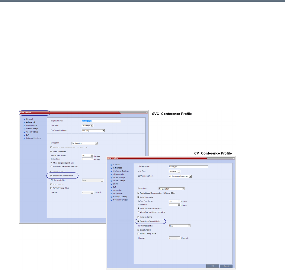
Sharing Content During Conferences
Polycom®, Inc. 140
Exclusive Content Mode
In this mode, the MCU prevents participants other than the current content sharer, from sharing content.
Exclusive content may be limited to the lecturer, as described below.
To modify exclusive content mode by granting (or canceling) of token ownership, see Giving and Canceling
Token Ownership (AVC Participants)).
Guidelines for Sharing Content in Exclusive Content Mode
●Exclusive Content Mode is available in all conferencing modes.
●Exclusive Content Mode is enabled or disabled (system default) by a check box in the Conference
Profile - Advanced tab, or during an ongoing conference using the Conference Properties -
Advanced tab.
●In Exclusive Content Mode, when the RESTRICT_CONTENT_BROADCAST_TO_LECTURER
system flag is set to:
NO - The first participant to send content becomes the Content Token holder, and releasing the
Content Token allows other participants to acquire the token, and begin transmitting content.
YES - Only the designated Lecturer can be the Content Token holder.
●The Exclusive Content Mode check box replaces the EXCLUSIVE_CONTENT_ MODE system flag
used in previous versions to control exclusive content mode for the system.
●In Exclusive Content Mode, an endpoint attempting to send content after another endpoint starts
sending content, is rejected with a momentary content interruption.

Sharing Content During Conferences
Polycom®, Inc. 141
Forcing Other Content Capabilities
The H239_FORCE_CAPABILITIES system flag allows additional control of content sharing:
●When set to NO (default) - The MCU merely verifies the endpoint supports the content protocols:
H.263 or H.264.
●When set to YES - The MCU verifies frame rate, bit rate, resolution, annexes, and all other
parameters of content as declared by an endpoint during the capabilities negotiation phase. If the
endpoint does not support the content capabilities of the MCU, the participant cannot share content
over a dedicated content channel.
Managing Noisy Content Connections
The system can identify participants sending frequent content display refresh requests (usually as a result
of a problematic network connection), which cause frequent refreshing of content display, and degrading of
viewing quality.
When the system identifies such “noisy” participants, it marks them (in the Conference Participants list,
Status column) as Noisy, and automatically suspends these requests to avoid affecting the quality of the
content viewed by the other conference participants.
This process is controlled by the following system flags:
●MAX_INTRA_REQUESTS_PER_INTERVAL_CONTENT -
The maximum number of refresh (intra) requests per 10-second intervals allowed for an endpoint.
Beyond that number, content sent by this participant is identified as “noisy”, and its refresh requests
are suspended.
Default setting: 3
●MAX_INTRA_SUPPRESSION_DURATION_IN_SECONDS_CONTENT -
The duration, in seconds, for ignoring the participant’s content display refresh requests.
Default setting: 10
●CONTENT_SPEAKER_INTRA_SUPPRESSION_IN_SECONDS -
The interval, in seconds, between content refresh (intra) requests sent from the MCU to the content
sender due to refresh requests initiated by other conference participants. Additional refresh requests
received within that interval are deferred to the next interval.
Default setting: 5

Sharing Content During Conferences
Polycom®, Inc. 142
Useful Procedures in Content Sharing
For all MCUs, content sharing parameters are defined in the conference profile Video Quality dialog box.
Defining Content Sharing Parameters for a Conference
The available content options change according to the selected conferencing mode, and in RealPresence
Collaboration Servers 1500/2000/4000 by the media cards installed (MPMx or MPMRx) as well.
To set the content sharing parameters:
»In the Content Video Definition section, set the values for the Content Settings and Protocol as
follows:
Content sharing Options
Field Description
Content Settings Select the transmission mode for the Content channel:
•Graphics — Basic mode, intended for normal graphics
• Hi-res Graphics — A higher bit rate intended for high resolution graphic display
•Live Video — Content channel displays live video
• Customized Content Rate - Manual definition of the Conference Content Rate,
mainly for cascading conferences.
For a description of each of these options, see Content Settings.
AS-SIP Content AS-SIP is a SIP implementation utilizing SIP’s built-in security features.
When selected, content is shared using the Multiple Resolutions mode, and is not
supported in any other content sharing mode.
Multiple Resolutions Select this check box to enable Multiple Content Resolutions mode, for both H.263
and H.264 content protocols.
When enabled, H.264 is always selected and cannot be modified.
Optional. Select additional protocols:
• H.263 - If the conference includes endpoints with H.263 capabilities.
• H.264 Cascade - If the conference includes cascading links and you want to
define the video settings for content sharing.
For more information, see Sharing Content Using Multiple Content Resolutions
Mode.
Content Protocol • H.263 - Content is shared using the H.263 protocol.
• H.263 & H.264 Auto Selection - Content is shared according to conference
participants capabilities.
• H.264 HD (default) - Content is shared using the H.264 HD protocol.
• H.264 Cascade Optimized - Content is shared using the H.264 content protocol
(fixed), and optimized for use in cascaded conferences.
For a detailed description of each of these settings, see Content Media Protocols.
Sharing Content During Conferences
Polycom®, Inc. 143
Content Resolution Select a Content Resolution from the pull-down menu.
The Content Resolutions available for selection are dependent on the content
sharing mode (Highest Common or Multiple Content Resolutions), Line Rate and
Content Settings selected for the conference.
For a full list of Content Resolutions see H.264 Supported Resolutions for AVC
(non-TIP) Conferences.
Note: This field is displayed only when H.264 Cascade Optimized is selected.
Send Content to
Legacy Endpoints
When enabled (default), content is sent to H.323/SIP/ISDN endpoints not supporting
current MCU content control protocol (legacy endpoints) over the people video layout
(see Sending Content to Legacy Endpoints).
H.264 High Profile
(RMX 1800 /
MPMRx only)
This field is unchecked by default, and is displayed only when conferencing mode is
VSW (Video Switching), and the selected Content Protocol is H.264 Cascade
Optimized.
Content sharing Options
Field Description
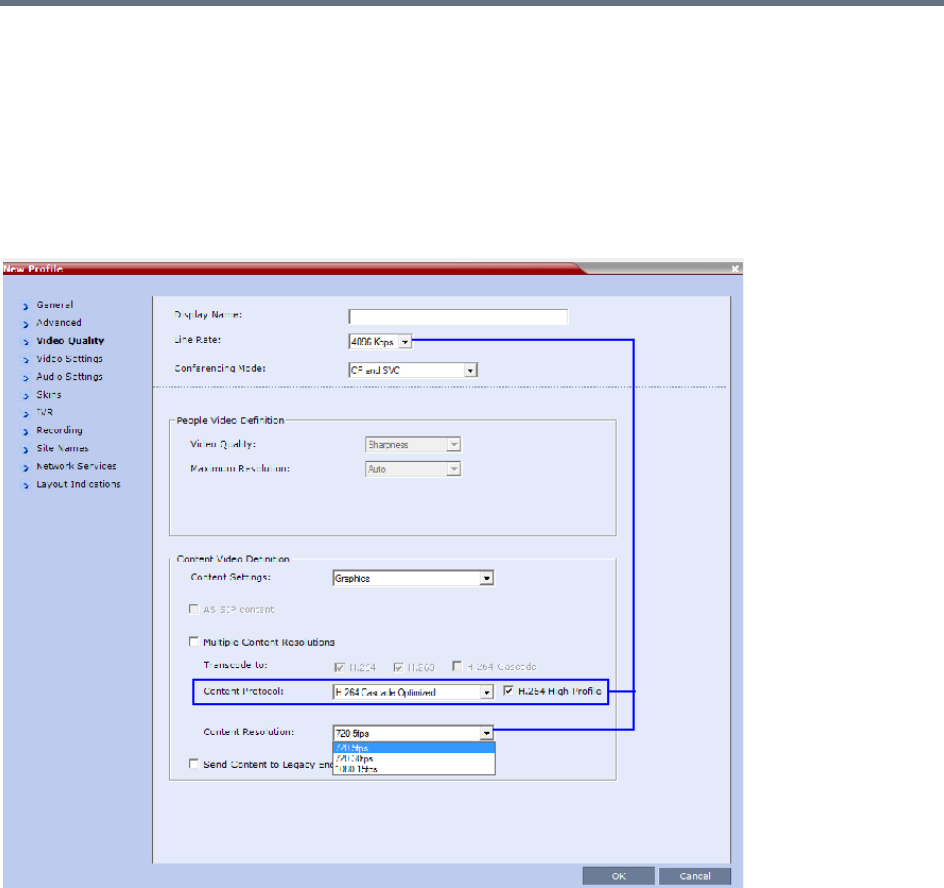
Sharing Content During Conferences
Polycom®, Inc. 144
H.264 Cascade Optimized Content Sharing
When H.264 Cascade Optimized is selected in conferences as the Content Protocol, an additional field,
Content Resolution is displayed in the Content Video Definition pane.
The Content Resolution value determines the fixed resolution and frame rate to be used for content
sharing in cascaded conferences.
The Content Resolutions available for selection are dependent on the Line Rate and Content Settings
selected for the conference.
An additional check box H.264 High Profile (unchecked by default) is displayed in the Video Quality dialog
box provided:
●The MCU is a RealPresence Collaboration Server 1800, or 2000/4000 containing MPMRx cards.
●TIP Compatibility (in the profile’s Advanced tab) is set to None.
The Content Rate drop-down menu list depends on Customized Content Rate being selected as the
Content Setting, and cannot exceed 66% of the conference line rate capability.
For information on the interaction of these parameters for Base Profile and High Profile settings, see H.264
Cascade Optimized (Fixed) Content Rates Tables.
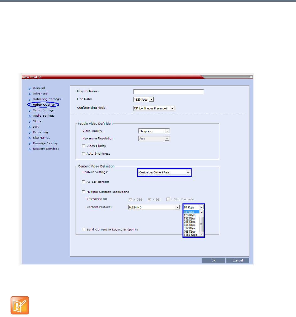
Sharing Content During Conferences
Polycom®, Inc. 145
Selecting a Customized Content Rate
To Select the Customized Content Rate:
1In the Content Settings list, select Customized Content Rate.
When selected, a drop-down menu of the available conference content rates is displayed. These
content rates vary according to the selected conference Line Rate.
2Select the required content rate.
If Customized Content Rate is already selected along with the content rate, and you attempt to
modify the conference line rate to a value that does not support the selected customized content rate,
an error message is displayed.
Modify the Content Line Rate or Conference Line Rate, or modify the Content Setting.
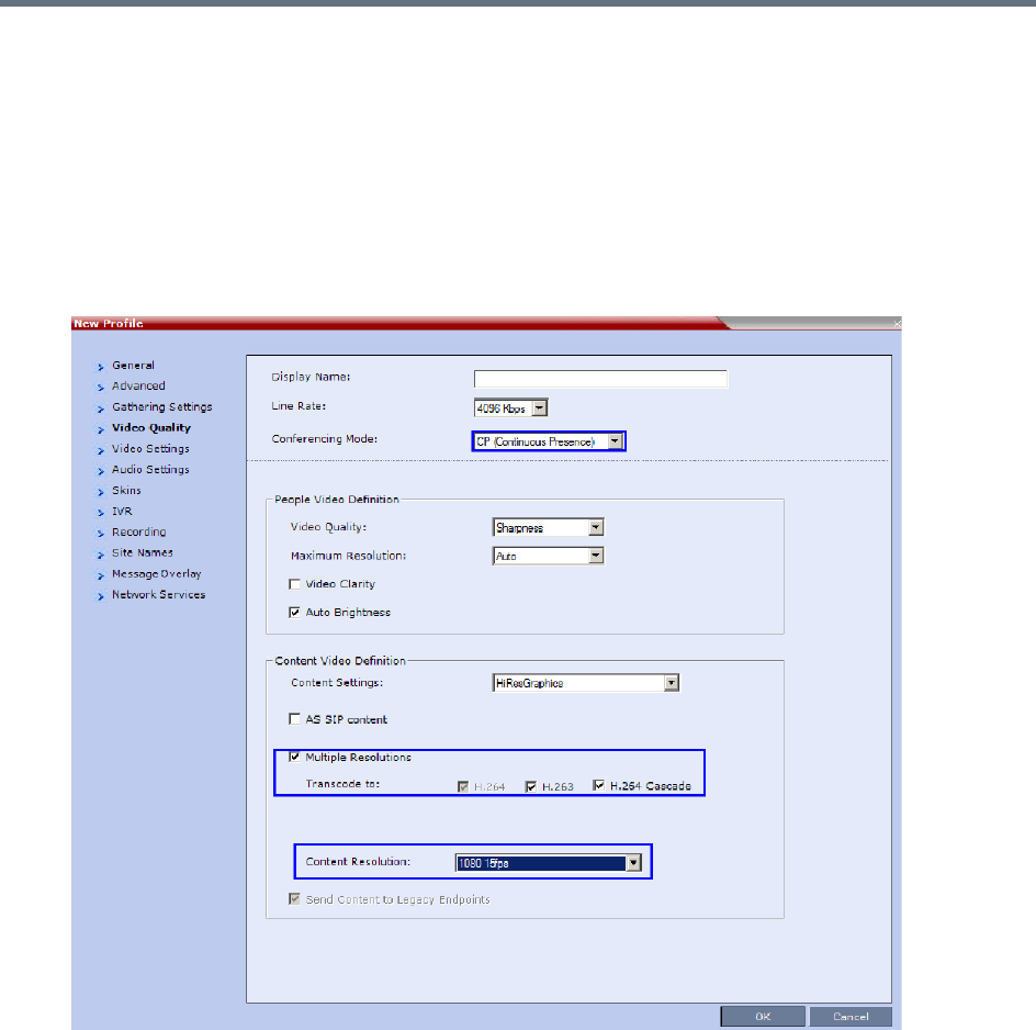
Sharing Content During Conferences
Polycom®, Inc. 146
Sharing Content in Multiple Content Resolutions Mode
For information on this content sharing mode see Multiple Content Resolutions.
The Multiple Content Resolutions mode can be modified in the conference Profile, in the Video Quality Tab.
To enable Multiple Content Resolutions:
1Select the Multiple Resolutions check box.
By default, H.264 is always selected, and cannot be modified.
2Select additional protocols:
H.263 - If the conference includes H.263 (only) capable endpoints.
H.264 Cascade - If the conference includes cascading links.
If H.264 Cascade is selected, select the Content Resolution.
3Click OK.
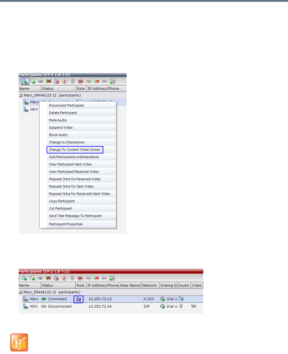
Sharing Content During Conferences
Polycom®, Inc. 147
Giving and Canceling Token Ownership (AVC Participants)
For information on exclusive content ownership, see Exclusive Content Mode.
To give token ownership:
1In the Participants list, right-click the AVC-enabled endpoint you wish to define as the exclusive
Content Token owner.
2Select Change To Content Token Owner in the drop-down menu.
The endpoint receives exclusive ownership of the Content Token, and an indication icon is displayed
in the Role column of the participant’s entry in the Participants list.
If another participant is currently sharing content, it is requested to release the token, and the
participant selected as the token owner is marked as exclusive. Once that participant shares content,
it cannot be snatched by other participants.
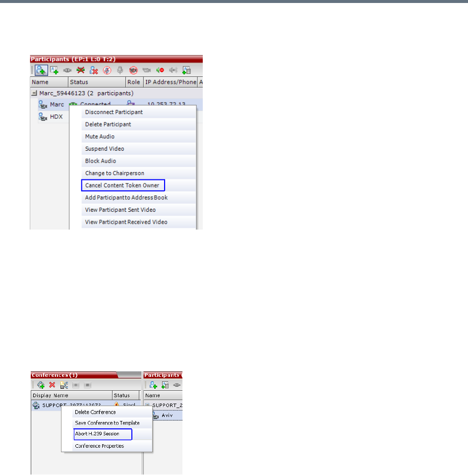
Sharing Content During Conferences
Polycom®, Inc. 148
To cancel token ownership:
1In the Participants list, right-click the endpoint that currently has Content Token ownership.
2Select Cancel Content Token Owner in the drop-down menu.
Content Token ownership is cancelled for the endpoint.
Stopping a Content Session
The Collaboration Server user can withdraw the content token from the current holder.
To end the current Content session:
»In the Conferences list pane, right-click the conference icon, and select Abort H.239 Session.
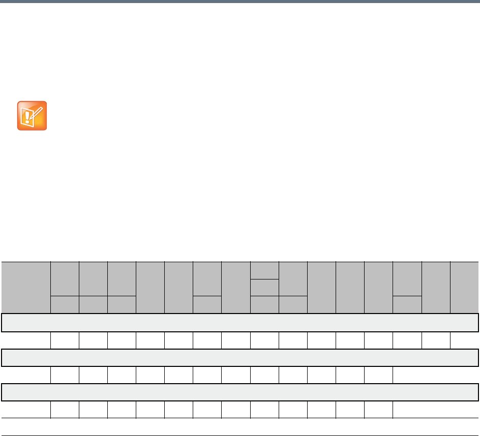
Sharing Content During Conferences
Polycom®, Inc. 149
Content Sharing Reference Tables
Resolutions and Content Rate Reference Tables
H.263 Content Rate Table
The table below describes the content rates for both Highest Common and Fixed content bit rates.
The values in the tables below indicate the maximum negotiated content rate (for both H.263 and
H.264) and resolution/frame rate (only for H.264).
When using Highest Common, endpoints may lower the content parameters, whereas when using
fixed rate, endpoints must comply with the content parameters as determined by the MCU.
The actual content parameters used by the content sharing endpoint are determined by that endpoint,
and may be lower.
Highest Common and Fixed Content Bit Rate Allocation for H.263
Content
Settings
/ MCU
64 128 256
384 512
768
1024
1152
1536
1920 2048 2560
3072
4096
6144
*
1280
96 192 320 832 1472 1728 3584
Graphics 33%
All 64 64 128 128 256 256 384 512 512 512 768 768 1280 1280
Hi-res Graphics 50%
All 64 128 192 256 384 512 512 768 1024 1024 1280 1536
Live Video 66%
All 64 128 256 384 512 512 768 1024 1280 1280 1536 1536
* This line rate is applicable only for RealPresence Collaboration Server 1800 or one with MPMRx card(s), or non-SVC-enabled conferencing
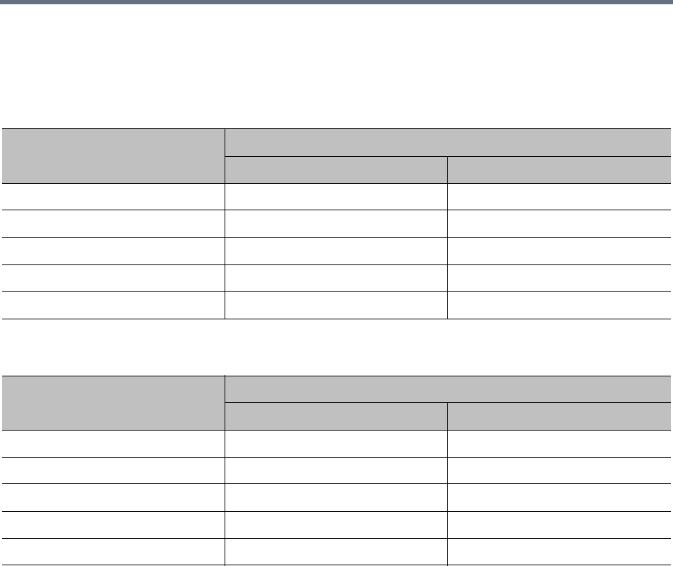
Sharing Content During Conferences
Polycom®, Inc. 150
H.264 Resolution per Content Rate Tables
The tables below describe the resolution as negotiated by the MCU according to the content rate, for both
base and high profiles.
* For RMX1800-0, maximum content resolution is HD1080p30.
Maximum Negotiated Resolution and Frame Rate per Content Rate for H.264 Base Profile
Bit Rate Allocated to Content
Channel (Kbps)
Maximum Negotiated Content
Resolution Frames/Second
64-512 H.264 HD720 5
512-768 H.264 HD720 30
768-1536 H.264 HD1080 15
1536-3072 H.264 HD1080 30 *
3072-4096 H.264 HD1080 60
Maximum Negotiated Resolution and Frame Rate per Content Rate for H.264 High Profile
Bit Rate Allocated to Content
Channel (Kbps)
Maximum Negotiated Content
Resolution Frames/Second
64-384 H.264 HD720 5
384-512 H.264 HD720 30
512-768 H.264 HD1080 15
768-2048 H.264 HD1080 30 *
2048-4096 H.264 HD1080 60
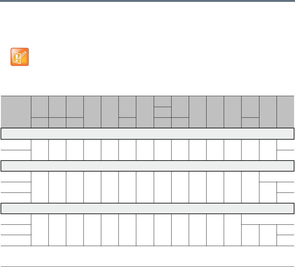
Sharing Content During Conferences
Polycom®, Inc. 151
H.264 Highest Common Content Rates Tables
The tables below summarize the Highest Common maximum content rates as negotiated by the MCU.
These tables apply only to single MCU (non-cascading) and non-SVC enabled conferences.
The values in the tables below are inapplicable if lower than those of the respective system flags (see
Setting the Minimum Content Rate for Each Content Quality Setting for H.264 HD).
Highest Common Content Bit Rate for H.264 Base Profile
Content
Settings
/ MCU
64 128 256
384 512
768
1024
1152
1536
1920 2048 2560
3072
4096
6144
*
1280
96 192 320 832 1472 1728 3584
Graphics 33%
≤1080p15 64 64 128 128 256 256 384 512 512 512 768 768 1280 1280
1080p30 ** 2048
Hi-res Graphics 50%
≤1080p15 64 128 192 256 384 512 512 768 1024 1024 1280 1536 1536
1080p30 ** 2048 2048
1080p60 ** 3072
Live Video 66%
≤1080p15 64 128 256 384 512 512 768 1024 1280 1280 1536 1536
1080p30 ** 2048 2560 3072
1080p60 ** 4096
* This line rate is applicable only for RealPresence Collaboration Server 1800 or one with MPMRx card(s), and for non-SVC-enabled conferencing
** These resolutions are applicable only for RealPresence Collaboration Server 1800 or one with MPMRx card(s) For RMX1800-0, maximum content
resolution is HD1080p30
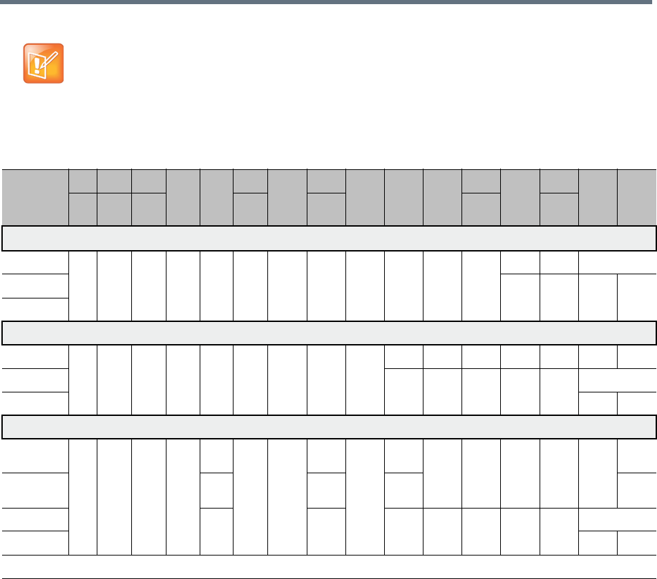
Sharing Content During Conferences
Polycom®, Inc. 152
High Profile is applicable only for Collaboration Servers 2000/4000 with MPMRx media card(s) or
Collaboration Server 1800.
Highest Common Content Bit Rate for H.264 High Profile
Content
Settings
/ MCU
64 128 256
384 512
768
1024
1152
1472 1536 1728
1920
2560
3072
4096
6144
*
96 192 320 832 1280 2048 3584
Graphics 33%
≤1080p15 64 64 128 128 256 256 384 384 512 512 512 768 768 1280
1080p30 768 768 1280 2048
1080p60
Hi-res Graphics 50%
≤1080p15 64 128 192 256 384 512 512 512 768 768 1024 1280 1280 1280 1280
1080p30 768 768 1024 1280 1536 2048
1080p60 2048 3072
Live Video 66%
≤1080p15-
AVC only
64 128 256 384 512 512 768 768 1024 1024 1280 1280 1280 1280 1280
≤1080p15-
SVC/Mixed
256 512 768 N/A
1080p30 384 768 1024 1024 1280 1536 2048 2048
1080p60 2560 4096
* This line rate is applicable only for non-SVC-enabled conferencing
Sharing Content During Conferences
Polycom®, Inc. 153
H.264 Cascade Optimized (Fixed) Content Rates Tables
The tables below summarize the content rates as they are determined by the MCU.
For information on the supported resolutions for each of the MCU types see H.264 Resolution per Content
Rate Tables.
H.264 Cascade Optimized Content Bit Rate for H.264 Base Profile
Cascade
Resolution
64 128 256
384 512 768
832
1152 1280
1472
1920
2048
3072 3584 4096
6144
*
1536
96 192 320 1024 1728 2560
Graphics 33%
720p5 64 64 128 128 256 256 256 256 256 256 512 512 512 512 512
720p30 512 512 512 512 512 512 768
1080p15 768 768 768 1152 1152 1152
1080p30 ** 2048
1080p60 **
Hi-res Graphics 50%
720p5 64 128 192 256 384 384 384 512 512 512 512 512 512 512 512
720p30 512 512 512 512 768 768 768 768 768
1080p15 768 768 768 768 768 1152 1152
1080p30 ** 2048 3072
1080p60 ** 3072
Live Video 66%
720p5 64 128 256 384 512 512 768 768 768 768 768 768 768 768 768
720p30 512 768 768 768 768 768 768 768 768 768
1080p15 768 768 768 768 1152 1152 1152 1152 1152
1080p30 ** 2048 2048 2560 3072
1080p60 ** 4096
* This line rate is applicable only for RealPresence Collaboration Server 1800 or one with MPMRx card(s), and for non-SVC-enabled conferencing
** These resolutions are applicable only for RealPresence Collaboration Server 1800 or one with MPMRx card(s). For RMX1800-0, maximum
content resolution is HD1080p30
Sharing Content During Conferences
Polycom®, Inc. 154
Note: High Profile support
High profile is supported only by RealPresence Collaboration Server with MPMRx card(s), or 1800.
H.264 Cascade Optimized Content Bit Rate for H.264 High Profile
Cascade
Resolution
64 128 256
384 512 768 832 1024
1152
1536 1728 1920 2048
2560
4096
6144
*
1280 3072
96 192 320 1472 3584
Graphics 33%
720p5 64 64 128 128 256 256 256 384 384 512 512 512 512 512 512
720p30 384 512 512 512 512 768 768 768
1080p15 512 512 512 512 768 1280 1280
1080p30 768 1280 2048
1080p60 2048
Hi-res Graphics 50%
720p5 64 128 192 256 384 384 384 512 512 512 512 512 512 512 512
720p30 384 384 512 512 512 768 768 768 768 768 768
1080p15 512 512 768 768 768 768 1280 1280 1280
1080p30 768 768 768 1024 1024 2048 2048
1080p60 2048 3072
Live Video 66%
720p5 64 128 256 256 384 512 512 512 512 512 512 512 512 512 512
720p30 512 512 512 768 768 768 768 768 768 768 768
1080p15 512 512 512 768 768 768 1280 1280 1280 1280 1280
1080p30 768 1024 1024 1280 1280 1280 2048 2048
1080p60 2560 4096
* This line rate is applicable only for non-SVC enabled conferencing

Polycom®, Inc. 155
Implementing Media Encryption for
Secured Conferencing
Encryption is available at the conference and participant levels, based on AES 128 (Advanced Encryption
Standard) and is fully H.233/H.234 compliant and the Encryption Key exchange DH 1024-bit
(Diffie-Hellman) standards.
Media Encryption Guidelines
●Encryption is not available in all countries and it is enabled in the MCU license. Contact Polycom
Support to enable it.
●Media encryption is supported in CP, SVC Only and mixed CP and SVC Conferencing Modes.
●Endpoints must support both AES 128 encryption and DH 1024 key exchange standards which are
compliant with H.235 (H.323) to encrypt and to join an encrypted conference.
●The encryption mode of the endpoints is not automatically recognized, therefore the encryption mode
must be set for the conference or the participants (when defined).
●Media Encryption for ISDN/PSTN participants is not supported in cascaded conferences.
●Conference level encryption must be set in the Profile, and cannot be changed once the conference
is running.
●If an endpoint connected to an encrypted conference stops encrypting its media, it is disconnected
from the conference.
●In Cascaded conferences, the link between the cascaded conferences must be encrypted in order to
encrypt the conferences.
●The recording link can be encrypted when recording from an encrypted conference to the
RealPresence Capture Server or RSSsystem that is set to encryption. For more information, see Dial
Out Recording Link Encryption.
●Encryption of SIP Media is supported using SRTP (Secured Real-time Transport Protocol) and the
AES key exchange method.
●Encryption of SIP Media requires the encryption of SIP signaling - TLS Transport Layer must be used.
●Encryption of SIP Media is supported in conferences as follows:
All media channels are encrypted: video, audio and FECC.
Collaboration Server SRTP implementation complies with Microsoft SRTP implementation.
LPR is not supported with SRTP.
The ENABLE_SIRENLPR_SIP_ENCRYPTION System Flag enables the SirenLPR audio
algorithm when using encryption with the SIP protocol. The default value of this flag is NO
meaning SirenLPR is disabled by default for SIP participants in an encrypted conference. To
enable SirenLPR the System Flag must be added to system.cfg and its value set to YES.
The SEND_SRTP_MKI System Flag enables or disables the inclusion of the MKI field in SRTP
packets sent by the Collaboration Server. The default value of the flag is YES.
Add the flag to system.cfg and set its value set to NO to disable the inclusion of the MKI field in SRTP
packets sent by the Collaboration Server when using endpoints that cannot decrypt SRTP-based
audio and video streams if the MKI (Master Key Identifier) field is included in SRTP packets sent by

Implementing Media Encryption for Secured Conferencing
Polycom®, Inc. 156
the Collaboration Server. When all conferences on the RMX will not have MS-Lync clients
participating and will have 3rd party endpoints participating. This setting is recommended for
Maximum Security Environments.
Add the flag to system.cfg and set its value set to YES when Microsoft Office Communicator and Lync
Clients. When any conferences on the RMX will have both MS-Lync clients and Polycom endpoints
participating. Some 3rd party endpoints may be unsuccessful in participating in conferences with this
setting.
Polycom endpoints function normally regardless of the setting of this flag.
For more information, see Modifying System Flags.
●In compliance with UC_APL_SEC_0013, the Collaboration Server 1500/2000/4000 supports an
additional Privacy Protocol AES_CM_128_HMAC_SHA1_32, in addition to
AES_CM_128_HMAC_SHA1_80. For more information see Media Encryption and Authentication.
Mixing Encrypted and Non-encrypted Endpoints in one
Conference
Mixing encrypted and non-encrypted endpoints in one conference is possible, based on the Encryption
option Encrypt When Possible in the Conference Profile - Advance dialog box. The behavior is different for
H.323/SIP and ISDN participants.
The option Encrypt When Possible enables the negotiation between the MCU and the endpoints and let
the MCU connect the participants according to their capabilities, where encryption is the preferred setting.
Defined participants that cannot connect encrypted are connected non-encrypted, with the exception of
dial-out SIP participants.
The same system behavior can be applied to undefined participants, depending on the setting of the System
Flag FORCE_ENCRYPTION_FOR_UNDEFINED_PARTICIPANT_IN_WHEN_AVAILABLE_MODE:
●When set to NO and the conference encryption in the Profile is set to Encrypt when possible, both
Encrypted and Non-encrypted undefined participants can connect to the same conferences, where
encryption is the preferred setting.
●When set to YES (default), undefined participants must connect encrypted, otherwise they are
disconnected.
For defined participants, connection to the conference is decided according to the encryption settings in the
conference Profile, the Defined Participant’s encryption settings.
For undefined participants, connection to the conference is decided according to the encryption settings in
the conference Profile, the System Flag setting and the connecting endpoint’s Media Encryption
capabilities.
•When the conference encryption is set to Encrypt when possible, SIP dial out participants
whose encryption is set to AUTO can only connect with encryption, otherwise they are
disconnected from the conference.
•In CISCO TIP environments, dial in endpoints that are registered to CUCM can only connect as
non-encrypted when the conference encryption is set to Encrypt when possible as the CUCM
server sends the Invite command without SDP.
•When the conference encryption is set to Encrypt when possible, SIP dial out participants
whose encryption is set to AUTO can only connect with encryption, otherwise they are
disconnected from the conference.

Implementing Media Encryption for Secured Conferencing
Polycom®, Inc. 157
Direct Connection to the Conference
The following table summarizes the connection status of participants, based on the encryption settings in
the conference Profile, the Defined Participant’s encryption settings or the System Flag setting for undefined
participants and the connecting endpoint’s Media Encryption capabilities.
Connection of Participants to the Conference based on Encryption Settings
Conference
Encryption
Setting
Defined Participant Undefined Participant
Encryption
Setting Connection status Connection Status
*Flag = No
Connection Status
*Flag = YES
No Encryption Auto Connected,
non-encrypted
Connected
non-encrypted
(Encryption is not
declared by the
Collaboration
Server, therefore the
endpoint does not
use encryption)
Connected
non-encrypted
(Encryption is not
declared by the
Collaboration
Server, therefore the
endpoint does not
use encryption)
No Connected,
non-encrypted
Yes Connected only if encrypted.
Non-encrypted endpoints are
disconnected as encryption is
forced for the participant.
Encrypt All Auto Connected, encrypted.
Non-encrypted endpoints are
disconnected
Connect only if
encrypted.
Non-encrypted
endpoints are
disconnected
Connect only if
encrypted.
Non-encrypted
endpoints are
disconnected
No Disconnected (cannot be
added to the conference)
Yes Connected, encrypted
Encrypt When
Possible
Auto All defined participants except
dial-out SIP participants:
•Connect encrypted -
Endpoints with encryption
capabilities.
•Connect non-encrypted -
endpoints without
encryption capabilities.
Defined dial-out SIP
participant:
•Connect only if encrypted.
•Non-encrypted endpoints
are disconnected.
Connect encrypted -
Endpoints with
encryption
capabilities.
Connect
non-encrypted -
endpoints without
encryption
capabilities
Connect only if
encrypted.
Non-encrypted
endpoints are
disconnected.
No Connected, non-encrypted
Yes Connected, encrypted
* Flag = FORCE_ENCRYPTION_FOR_UNDEFINED_PARTICIPANT_IN_WHEN_AVAILABLE_MODE

Implementing Media Encryption for Secured Conferencing
Polycom®, Inc. 158
Connection to the Entry Queue
An undefined participant connecting to an Entry Queue inherits the encryption characteristics of the Entry
Queue as defined in the Entry Queue’s profile.
Participants can be moved from the Entry Queue and the destination conference if both conferencing
entities have the same Profile settings, i.e. from SVC Only Entry Queue to SVC Only conference and from
mixed CP and SVC Entry Queue to a mixed CP and SVC conference, etc.
The following table summarizes the connection possibilities for a participant that is to be moved from an
Entry Queue to a destination conference for each of the conference Profile and Entry Queue encryption
options.
Moving from the Entry Queue to Conferences or Between Conferences
Participants can be moved from the Entry Queue and the destination conference if both conferencing
entities have the same Profile settings, i.e. from SVC Only Entry Queue to SVC Only conference and from
mixed CP and SVC Entry Queue to a mixed CP and SVC conference, etc.
When moving participants from the Entry Queue to the destination conference, or when the Collaboration
Server user moves AVC participants from one conference to another (SVC participants cannot be moved
between conferences), the connection rules are similar and they are summarized in the table below:
Connection of Undefined Participants to the Entry Queue Based on Encryption Settings
Entry Queue Encryption
Setting
Undefined Participant Connection to the Entry Queue
*Flag = No *Flag = YES
No Encryption Connected, non-encrypted
(Encryption is not declared by the
Collaboration Server, therefore endpoint
does not use encryption)
Connected, non-encrypted
(Encryption is not declared by the
Collaboration Server, therefore endpoint
does not use encryption)
Encrypt All Connected only if encrypted.
Non-encrypted endpoints are
disconnected
Connected only if encrypted.
Non-encrypted endpoints are
disconnected
Encrypt When Possible Connected encrypted - Endpoints with
encryption capabilities.
Connected non-encrypted - endpoints
without encryption capabilities
Connected only if encrypted.
Non-encrypted endpoints are
disconnected.
* Flag = FORCE_ENCRYPTION_FOR_UNDEFINED_PARTICIPANT_IN_WHEN_AVAILABLE_MODE
Moving participants from entry queue to conference / between conferences depending on encryption settings
Destination
Conference
Encryption Setting
Current Participant Encryption Status
Encrypted Non-Encrypted
*Flag = NO *Flag = YES *Flag = NO *Flag = YES
No Encryption Move succeeds, connected encrypted Move succeeds, connected
non-encrypted

Implementing Media Encryption for Secured Conferencing
Polycom®, Inc. 159
Recording Link Encryption
Recording Links are treated as regular participants, however the system flag
ALLOW_NON_ENCRYPT_RECORDING_LINK_IN_ENCRYPT_CONF must be set to YES if a
non-encrypted Recording Link is to be allowed to connect to an encrypted conference.
The following table summarizes the connection possibilities for a Recording Link that is to be connected to
a conference for each of the conference profile and Entry Queue encryption options.
Enabling Media Encryption for a Conference
Media encryption is enabled at three levels:
●MCU level - Setting the Encryption Flags
●Conference level - Enabling Encryption in the Profile
●Participant level - Enabling Encryption at the Participant Level
You must first set the system flags for the MCU before media encryption can be enabled for the conference
and participants.
Encrypt All Move succeeds, connected encrypted. Move fails, disconnected.
Encrypt When Possible Move succeeds,
connected
encrypted
Move succeeds,
connected
encrypted
Move succeeds,
connected
non-encrypted
Connected only if
endpoint was a
defined participant
in the source
conference.
Otherwise, move
fails.
* Flag = FORCE_ENCRYPTION_FOR_UNDEFINED_PARTICIPANT_IN_WHEN_AVAILABLE_MODE
Connections by Recording Link and Conference Encryption Settings
Conference
Profile Setting
Recording Link Connection Status according to flag:
ALLOW_NON_ENCRYPT_RECORDING_ LINK_IN_ENCRYPT_CONF
YES NO
Encrypt All Connected encrypted if possible,
otherwise connected non-encrypted.
Connected only if encrypted, otherwise
disconnected
No Encryption Connected non-encrypted Connected non-encrypted
Encrypt when possible Connected encrypted if possible,
otherwise connected non-encrypted.
Connected encrypted if possible,
otherwise connected non-encrypted.
Moving participants from entry queue to conference / between conferences depending on encryption settings
Destination
Conference
Encryption Setting
Current Participant Encryption Status
Encrypted Non-Encrypted
*Flag = NO *Flag = YES *Flag = NO *Flag = YES

Implementing Media Encryption for Secured Conferencing
Polycom®, Inc. 160
Setting the Encryption Flags
Enabling the media encryption for the MCU is usually performed once an it is applicable to all conferences
running on the MCU.
To modify the Encryption flags:
1Click Setup>System Configuration.
The System Flags dialog box opens.
2Set the
FORCE_ENCRYPTION_FOR_UNDEFINED_PARTICIPANT_IN_WHEN_AVAILABLE_MODE flag
to YES or NO.
3If recording will be used in encrypted conferences, set the
ALLOW_NON_ENCRYPT_RECORDING_LINK_IN_ENCRYPT_CONF flag to YES or NO.
4Click OK.
For more information, see Modifying System Flags.
5Reset the MCU for flag changes to take effect.
Enabling Encryption in the Profile
Encryption for the conference is in the Profile and cannot be changed once the conference is running.
To enable encryption at the conference level:
»In the Conference Profile Properties – Advanced dialog box, select one of the following Encryption
options:
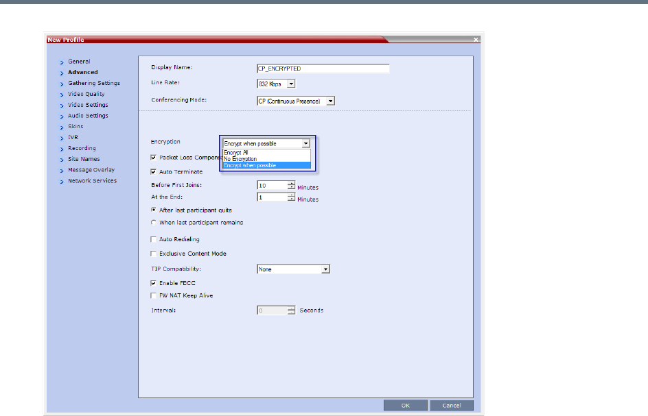
Implementing Media Encryption for Secured Conferencing
Polycom®, Inc. 161
Encrypt All - Encryption is enabled for the conference and all conference participants must be
encrypted.
No Encryption - Encryption is disabled for the conference.
Encrypt when possible - Enables the negotiation between the MCU and the endpoints and let
the MCU connect the participants according to their capabilities, where encryption is the preferred
setting. For connection guidelines see Mixing Encrypted and Non-encrypted Endpoints in one
Conference.
For more information about recording encrypted conferences, see Dial Out Recording Link
Encryption.
Enabling Encryption at the Participant Level
You can select the encryption mode for each of the defined participants. Encryption options are affected by
the settings of the flag in the system configuration. Undefined participants are connected with the Participant
Encryption option set to Auto, inheriting the conference/Entry Queue encryption setting.
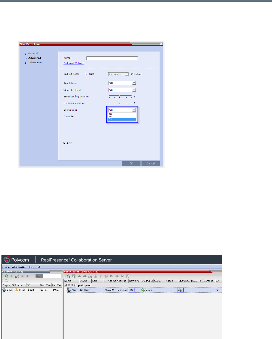
Implementing Media Encryption for Secured Conferencing
Polycom®, Inc. 162
To enable encryption at the participant level:
»In the Participant Properties – Advanced dialog box, in the Encryption list, select one of the
following options: Auto, On, or Off.
Auto - The participant inherits the conference/Entry Queue encryption setting. The participant
connects as encrypted only if the conference is defined as encrypted.
Yes - The participant joins the conference/Entry Queue as encrypted.
No - The participant joins the conference/Entry Queue as non-encrypted.
Monitoring the Encryption Status
The conference encryption status is indicated in the Conference Properties - General dialog box.
The participant encryption status is indicated by a check mark in the Encryption column in the Participants
list pane.
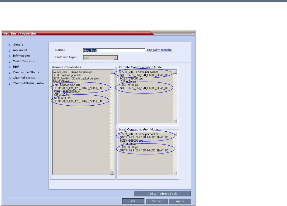
Implementing Media Encryption for Secured Conferencing
Polycom®, Inc. 163
The participant encryption status is also indicated in the Participant Properties – SDP tab, where SRTP
indication is listed for each encrypted channel (for example, audio and video).
An encrypted participant who is unable to join a conference is disconnected from the conference. The
disconnection cause is displayed in the Participant Properties – Connection Status dialog box, Security
Failure indication, and the Cause box identifies the encryption related situation.
For more information about monitoring, see Conference and Participant Monitoring.
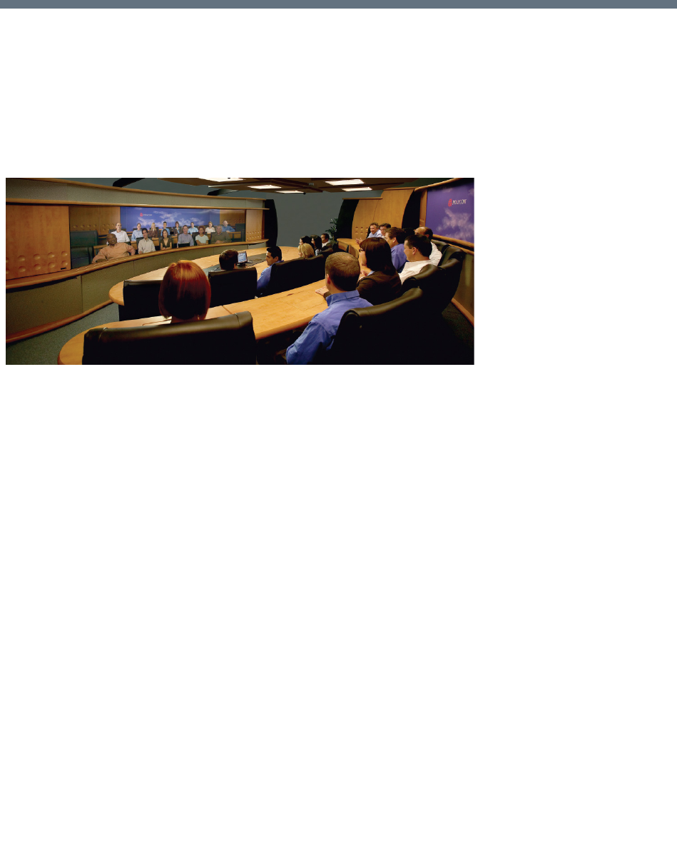
Polycom®, Inc. 164
Setting Conferences for Telepresence
Mode (AVC CP)
Collaboration Server supports the Telepresence Mode in AVC CP conferences allowing multiple participants
to join a telepresence conference from RPX and OTX high definition rooms as well as traditional, standard
definition video conferencing systems.
OTX (Telepresence) and RPX (RealPresence) room systems are configured with high definition cameras
and displays that are set up to ensure that all participants share a sense of being in the same room.
Participants using two RealPresence RPX HD 400 Room Systems
The following are examples of situations where an Collaboration Server is needed for Telepresence
configurations:
●RPX to OTX
●RPX 2-cameras/screens to RPX 4-cameras/screens
●3 or more RPXs
●3 or more OTXs
Collaboration Server Telepresence Mode Guidelines
System Level
●The Collaboration Server system must be licensed for Telepresence Mode.
●The system must be activated with a Telepresence enabled license key.
Conference Level
●The Telepresence Mode and Telepresence Layout Mode fields are only displayed in the Conference
Profile dialog box if the Collaboration Server has a Telepresence license installed.
●A Telepresence conference must have Telepresence Mode enabled in its profile.
●In Telepresence Mode, ITP sites are automatically detected.

Setting Conferences for Telepresence Mode (AVC CP)
Polycom®, Inc. 165
●When Telepresence Mode is selected in a conference profile, the following options are disabled:
Borders
Site Names
Speaker Indication
Skins
Same Layout
Presentation Mode
Auto Layout
Lecture Mode
●The master (center) camera is used for video, audio and content.
●Conference Templates can be used to simplify the setting up Telepresence conferences where
precise participant layout and video forcing settings are crucial. Conference Templates:
Save the conference Profile.
Save all participant parameters including their Personal Layout and Video Forcing settings.
●An ongoing Telepresence conference can be saved to a Conference Template for later re-use.
For more information see Conference Templates.
●Telepresence Mode and its associated layouts are not supported by Collaboration Server (RMX)
1800-0.
Automatic Detection of Immersive Telepresence (ITP) Sites
When the conference Telepresence Mode is set to Auto (Default) ITP endpoints are automatically detected.
If an ITP endpoint is detected in such conference, ITP features are applied to all endpoints and the
Collaboration Server sends conference video with the following options disabled:
●Borders
●Site names
●Speaker indication
●Skins
●Same Layout
●Presentation Mode
●Auto Layout
●Lecture Mode
The ITP features are dynamic, and if all ITP endpoints disconnect from the conference, normal conference
video is resumed for the remaining all participants. ITP features are re-applied to all participants should an
ITP endpoint re-connects to that conference.
Horizontal Striping
Horizontal Striping is used by the Collaboration Server in order to prevent cropping and preserve the aspect
ratio of video for all Telepresence Modes.
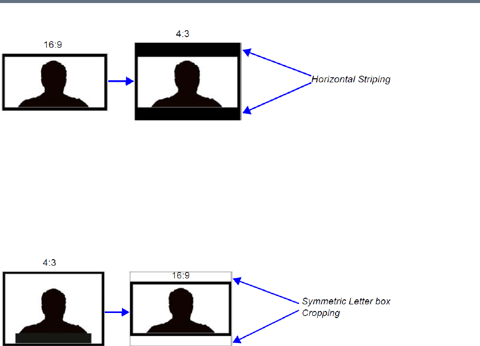
Setting Conferences for Telepresence Mode (AVC CP)
Polycom®, Inc. 166
Cropping
Cropping is used by the Collaboration Server in order to preserve the aspect ratio of video for all
Telepresence Modes.
Cropping is controlled by the ITP_CROPPING system flag in the system configuration, providing different
cropping options according to the endpoints participating in the Telepresence conference.
By default, the flag is set to ITP. In this mode, the area to be stripped is cropped equally from the top and
the bottom (as shown in the example below). For more details, see Modifying System Flags.
Gathering Phase with ITP Room Systems
When a conference is configured to include a Gathering Phase, only one endpoint name is displayed for the
ITP room in the connected participant list of the Gathering slide. The ITP room endpoint with the suffix 1 in
its name receives the Gathering slide.
Aspect ratio for standard endpoints
Standard endpoints (non-ITP) receive video from the Collaboration Server with the same aspect ratio as that
which they transmitted to the Collaboration Server.
Skins and Frames
When Telepresence Mode is enabled, no Skin is displayed and the system uses a black background.
Frames around individual layout windows and the speaker indication are disabled.
RPX and OTX Video Layouts
Additional video layouts have been created to give Telepresence operators more video layout options when
configuring OTX and RPX room systems. These additional video layout options are available to all
endpoints on both conference layout and Personal Layout levels.
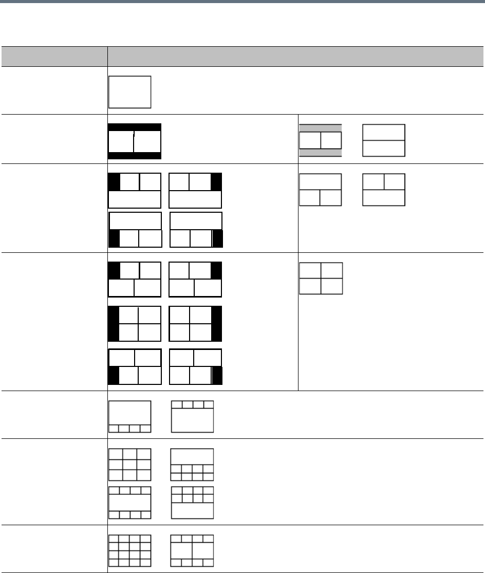
Setting Conferences for Telepresence Mode (AVC CP)
Polycom®, Inc. 167
The following example illustrates the use of standard and additional Collaboration Server Telepresence
layouts when connecting four Room Systems as follows:
●Two OTX Room Systems
OTX / RPX – Additional Video Layouts
Number of Endpoints Layouts
1
2
3
4
5
9
10+
4:3 4:3
4:3 4:3 4:3 4:3
4:3 4:3 4:3 4:3
4:3 4:3 4:3 4:3
4:3 4:3
4:34:3
4:3
4:34:3
4:3
4:3 4:3 4:3 4:3
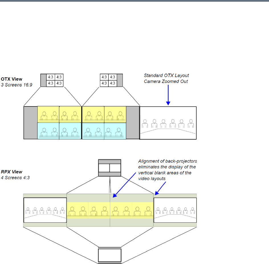
Setting Conferences for Telepresence Mode (AVC CP)
Polycom®, Inc. 168
2 active cameras
6 screens
●Two RPX Room Systems
8 cameras
8 screens
RPX and OTX Room System connected using the RealPresence Collaboration Server

Setting Conferences for Telepresence Mode (AVC CP)
Polycom®, Inc. 169
Room Switch Telepresence Layouts
The Room Switch Telepresence layouts normally controlled by the MLA can be managed by the MCU to
speed updating the conference layouts in large conferences with many endpoints.
Whether the MLA or the MCU controls the Room Switch Telepresence layouts is determined by the
MANAGE_TELEPRESENCE_ROOM_SWITCH_LAYOUTS flag. This flag must be manually added before
changing its value. No system reset is required.
The values are:
●NO (Default) - The MCU does not manage Telepresence Room Switch Layouts and they continue to
be managed by the MLA.
●YES - The MCU manages Telepresence Room Switch Layouts.
When the MCU controls the Telepresence Room Switch layouts
(MANAGE_TELEPRESENCE_ROOM_SWITCH_LAYOUTS = YES) the display is affected according to the
Telepresence Mode Settings in the Conference Profile as follows:
●If the Telepresence Mode = ON
If no ITP endpoints are connected to the conference, the RMX Room Switch layout applies, in
which case only the speaker is seen.
When a single participant using an ITP endpoint with either single or multiple screens connects to
the conference, the participant will see black screens.
●If the Telepresence Mode = AUTO
If no ITP endpoints are connected to the conference, the RMX CP layout applies (unless the
conference layout is defined).
When a single participant using an ITP endpoint with multiple screens connects to the conference,
the participant will see black screens.
When a single participant using an ITP endpoint with a single screen connects to the conference,
the MCU will display a self-view of the participant.
●When a TIP system with 3 screens joins a conference, the layout is updated on all screen
simultaneously.
●When a Polycom ITP system with 2, 3, or 4 screens joins the conference, the layout is updated on all
screens simultaneously.
Telepresence Display Decision Matrix
How the speaker video is displayed on the screens of the conference participants is dependent on the
relationship between the number of screens the speaker endpoint contains and the number of screens of
the endpoints of the other conference participants.
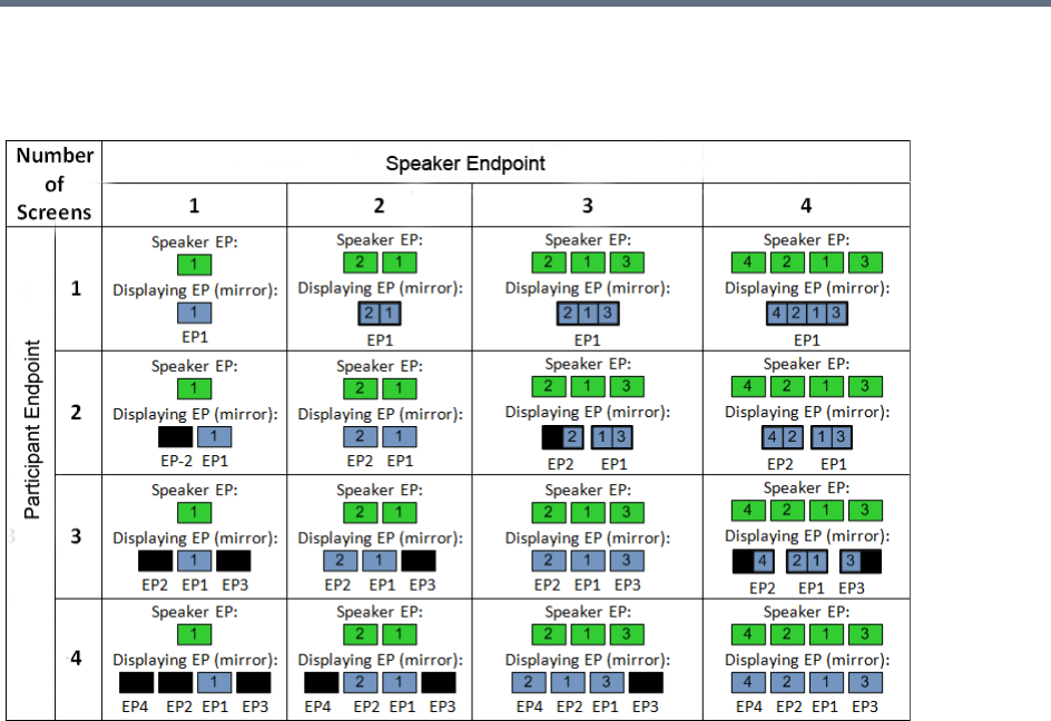
Setting Conferences for Telepresence Mode (AVC CP)
Polycom®, Inc. 170
The following Telepresence Display Decision Matrix table below indicates how the speaker video will be
displayed on the various participant endpoints, when the MCU is managing Telepresence Room Switch
conference layouts.
For example, if the speaker’s endpoints has two screens and the participant’s endpoint only one, the
participant’s display is divided into two video layout cells with each video layout cell showing the input of one
of the speaker’s screens (endpoint).
If the participant endpoint has two screens, and the speaker endpoint only one, the speaker’s video will be
displayed on one of the participant’s screens, while the second screen remains black.
Guidelines for Managing the Room Switch Telepresence Layouts by
the MCU
●Only Room Switch layouts can be managed by the MCU. CP (Continuous Presence) layouts continue
to be managed by the MLA.
●Only CP-AVC conferences are supported.
●Lync Clients (with CSS add-in) are supported. Microsoft Lync is not supported by Collaboration
Server (RMX) 1800-0.
●SVC endpoints are not supported.
●It is recommended that the Speaker Change Threshold be set to 3 seconds.
●Telepresence endpoints are named using a text name followed by a number. For example, if an OTX
Telepresence room is named Oak, the three endpoint names would be Oak1, Oak2, and Oak3.
●Lecture mode is not supported in Telepresence Room Switch conferences managed by the MCU.
(This is because in Lecture mode, unlike Room Switch mode, the lecturer receives the CP layout of
conference participants.)

Setting Conferences for Telepresence Mode (AVC CP)
Polycom®, Inc. 171
●Personal layouts are disabled. Therefore, any features that use personal layouts like Click&View can
not be used to change the layout, and Click&View DTMF digits will be ignored.
●Changing the flag affects only future conferences. Conferences currently running are not affected.
●The Send Content To Legacy Endpoints feature is enabled by default when Telepresence mode is
enabled.
●Layout attributes (no skins, no site names and no borders) should continue for Telepresence layouts
managed by the RMX.
Speaker Priority in CP Video Layouts
The purpose of Speaker Priority Mode is to provide high visibility to the speaker's room and to ensure that
the active speaker in the conference is always displayed in the video layout, and displayed in the best way
possible. If there is space in the layout while the active speaker is displayed, previous speakers are also
displayed.
Reserved Screens
When Speaker Priority mode is selected each Room System reserves screens to provide high visibility
according to maximum number of room-screens in the conference, displaying the active speaker in the
largest video layout cell available.
The Speaker Priority option is selected in the Video Settings tab of the Profile dialog. For more information
see Selecting Speaker Priority
The number of reserved screens depends on the maximum number of room-cameras connected to the
conference. Typically, two room-cameras are displayed one screen, three room-cameras on three screens,
and four room-cameras on two screens.
Reserved screens include an Overlay Layout (Filmstrip) that may be populated with other conference
participants after the Grid Screen(s) have been fully populated with additional conference participants. See
Video Layout Examples.
Grid Screens
Grid screens are symmetric video layouts (2x2, 3x3, 4x4) that are populated with other conference
participants after the Reserved Screens are populated with the current and previous speakers. Grid screens
are only available when the room system has more screens than the number of reserved screens—grid
screens typically exist within 2 or 4 screen systems. See Video Layout Examples.
Video Layout Examples
●A three-screen Room System will reserve three screens if another three-camera Room System
participates in the conference. If the active speaker is using a single camera endpoint, the active
speaker is displayed on a full screen while the two previous speakers are displayed on the other two
screens.
●Irrespective of whether the receiving Room System has more screens than the active speaker’s
Room System:
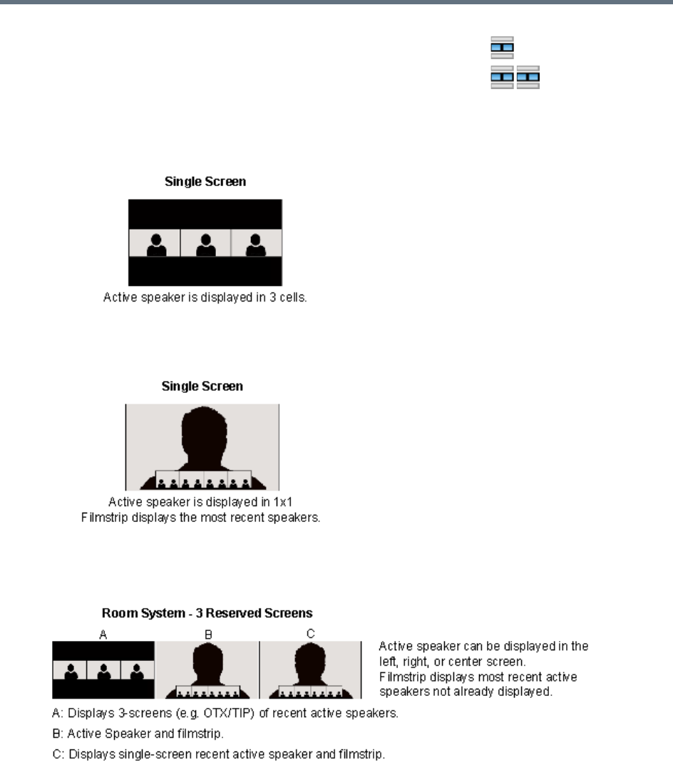
Setting Conferences for Telepresence Mode (AVC CP)
Polycom®, Inc. 172
●Three-screen Room Systems (e.g. OTX / TIP) will not zoom out when Speaker Priority is selected.
The layout below is used when the active speaker is using a 3-screen room system and the viewing
endpoint is single-screen endpoint.
The layout below is used when the active speaker is using a single-screen endpoint and the viewing
endpoint is single-screen endpoint.
The layout below is used when the active speaker is using a single-screen endpoint and the viewing
endpoint is 3-screen endpoint.
•An active speaker’s two-camera room is displayed on one screen.
•An active speaker’s four-camera room is displayed on two screens.
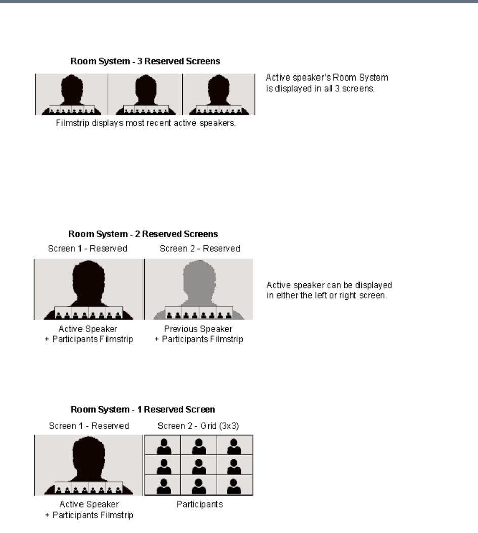
Setting Conferences for Telepresence Mode (AVC CP)
Polycom®, Inc. 173
The layout below is used when the active speaker is using a 3-screen room system and the viewing
endpoint is 3-screen endpoint.
●If a two-screen Room System is displaying a active speaker using a one-camera endpoint, and a
previous speaker also using a one-camera endpoint, the following layouts will be displayed on the
Room System’s two screens.
The layout below is used when the conference includes 4-screen rooms where both the active
speaker and the previous active speaker are using single-screen endpoints.
The layout below is used when the conference includes 1, 2, and 3-screen rooms where the active
speaker is using a single-screen endpoint.
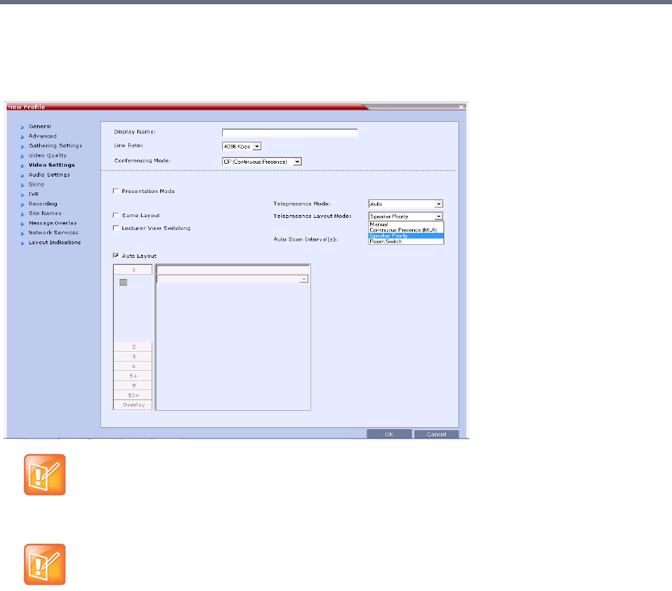
Setting Conferences for Telepresence Mode (AVC CP)
Polycom®, Inc. 174
Selecting Speaker Priority
Speaker Priority is selected in the Telepresence Layout Mode menu in the Video Settings tab of the Profile
dialog. For more information see Defining AVC CP Conferencing Profiles.
Sending Content to Legacy Endpoints in Telepresence
Conferences
The Collaboration Server can be configured to manage the layouts of to H.323/SIP/ISDN endpoints that do
not support H.239 Content (legacy endpoints) over the video (people) channel in Telepresence conferences
when Content is being sent. This feature is controlled using the
FORCE_LEGACY_EP_CONTENT_LAYOUT_ON_TELEPRESENCE flag. This flag must be added to
change the value.
The values of the flag are:
●NO (Default) - The MCU does not manage the layouts while Content is sent. Personal layout
changes, for example, by MLA, override the default MCU layout. Legacy endpoints may not display
Content in Telepresence conferences due to layout changes.
Telepresence Mode License
The Telepresence Layout Mode field is enabled only if the Collaboration Server system is licensed for
Telepresence Mode.
AVC endpoints only
Telepresence features are currently only supported in AVC-CP conferences.
SVC or SVC and CP Mixed Mode conferences are not supported.

Setting Conferences for Telepresence Mode (AVC CP)
Polycom®, Inc. 175
●YES - The MCU manages the layouts while Content is sent. Personal layout changes, for example,
by MLA, are ignored. The layouts for legacy endpoints are managed by the MCU.
Guidelines for Sending Content to Legacy Endpoints in Telepresence
Conferences
●MLA layout change requests for legacy endpoints will be ignored until Content is stopped. At that
point, MLA can be used again.
●Click&View can not be used to change the layout while Content is being sent.
●The Polycom Touch Control can not be used to change the layout while Content is being sent.
Content Display on Legacy Endpoints in Telepresence Conferences
When Content is sent to legacy endpoints in Telepresence conferences, their video layout automatically
changes to the Content layout which is defined by the system flag
LEGACY_EP_CONTENT_DEFAULT_LAYOUT. If MLA is managing the Telepresnce layout prior to Content
being sent, the MCU takes over managing the layout of Legacy endpoints once Content is started. The video
layouts of the other conference participants continue to be managed by MLA.
If MLA was managing the Telepresence layouts, when Content ends, control of the layouts for legacy
endpoints goes back to the MLA after a short time.
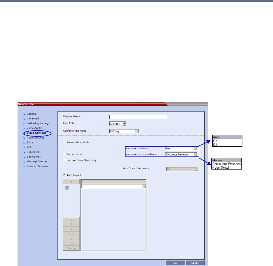
Setting Conferences for Telepresence Mode (AVC CP)
Polycom®, Inc. 176
Enabling Telepresence Mode
Telepresence Mode must be configured in a new or existing Conference Profile.
To enable Telepresence in a new or existing Conference Profile:
1In the RMX Management pane, click Conference Profiles.
2Click the New Profiles button or open an existing Conference Profile.
3Define the various profile General, Advanced, Gathering Settings and Video Quality parameters.
For more information on defining Profiles, see Defining New Profiles.
4Click the Video Settings tab.
5In the Telepresence Mode field, select one of the following options:
OFF - When OFF is selected, normal conference video is sent by the Collaboration Server.
AUTO (Default) - The ITP features are dynamic. When AUTO is selected and an ITP endpoint is
detected, ITP features are applied to the conference video for all participants. If all ITP endpoints
disconnect from the conference, normal conference video is resumed for all remaining
participants. ITP features are re-applied for all participants should an ITP endpoint re-connect to
the conference.
When Telepresence Mode is set to Auto and a one-screen Telepresence unit is in use, the
Collaboration Server controls layouts instead of the MLA. For more information see Polycom
Multipoint Layout Application (MLA) User’s Guide for Use with Polycom Telepresence Solutions.
ON - ITP features are always applied to the conference video for all participants regardless of
whether there are ITP endpoints connected or not.

Setting Conferences for Telepresence Mode (AVC CP)
Polycom®, Inc. 177
6In the Telepresence Layout Mode field, select the Telepresence Layout Mode to be used in the
conference. This field is used by VNOC operators and Polycom Multi Layout Applications to retrieve
Telepresence Layout Mode information from the Collaboration Server.
The following modes can be selected (as required by the VNOC and Polycom Multi Layout
Applications):
Manual
Continuous presence - Room Continuous Presence (Default)
Room Switch - Voice Activated Room Switching
7Select the required video layout.
8Click OK.
•When Telepresence Mode is enabled, the Skins options are disabled as the system uses a black
background and the frames and speaker indication are disabled.
It is recommended that the PRESERVE_PARTY_CELL_ON_FORCE_LAYOUT System Flag be set
to YES if the Collaboration Server is used primarily for ITP conferences with MLA.
•For more information see the flag description in .
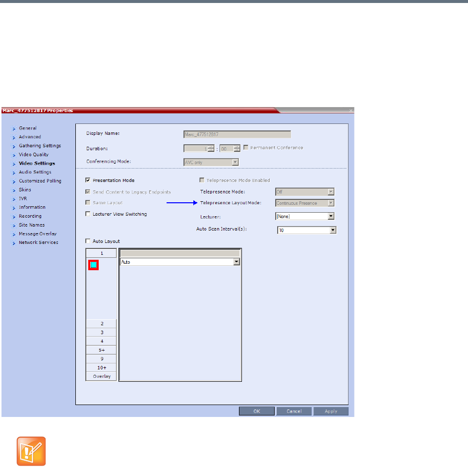
Setting Conferences for Telepresence Mode (AVC CP)
Polycom®, Inc. 178
Monitoring Telepresence Mode
Monitoring Ongoing Conferences
An additional status i
ndicator, Telepresence Mode Enabled, is displayed in the Conference Properties -
Video Settings tab when monitoring ongoing conferences.
If Telepresence Mode is enabled, a check mark is displayed in the check box. This option is grayed as this
is a status indicator and cannot be used to enable or disable Telepresence Mode.
The Telepresence Mode Enabled, Telepresence Mode and Telepresence Layout Mode fields are
only enabled if the Collaboration Server has a Telepresence license installed.

Setting Conferences for Telepresence Mode (AVC CP)
Polycom®, Inc. 179
Monitoring Participant Properties
An additional status indicator, Telepresence, is displayed in the Participant Properties - Advanced tab when
monitoring conference participants.
The Telepresence mode of the participant is indicated:
●RPX - the participant’s endpoint is transmitting 4:3 video format.
●OTX - the participant’s endpoint is transmitting 16:9 video format.
●None.

Setting Conferences for Telepresence Mode (AVC CP)
Polycom®, Inc. 180
Creating Multiple Cascade Links Between
Telepresence Conferences
You can create multiple Cascading links between Collaboration Servers hosting conferences that include
Immersive Telepresence Rooms (ITP) such as Polycom’s OTX and RPX Room Systems.
Guidelines for Creating Multiple Cascading Links between
Conferences
●Basic Cascading topology is used. For more information see Basic Cascading Using IP Cascaded
Link.
●Multiple Cascade Links between conferences are implemented by creating a Link Participant which
consists of a main link and sub-links which are automatically generated and sequentially numbered.
For more information see Creating a Link Participant, Creating a Link Participant.
●All cascaded links must use H.323 protocol.
●Multiple Cascade Links are supported in CP conferencing mode.
●The number of cascading links is defined manually according to the maximum number of Room
System cameras in the cascaded conference.
●When the active speaker is in an Immersive Telepresence Room, Multiple Cascade Links are used,
one link for each of the Room System’s cameras.
An RPX 4xx Room System requires 4 Cascaded Links to carry the video of its 4 cameras.
An RPX 2xx Room System requires 2 Cascaded Links to carry the video of its 2 cameras.
An OTX 3xx Room System requires 3 Cascaded Links to carry the video of its 3 cameras. The
OTX Room System must be configured as Room Switch in order to send multiple streams. When
configured in CP Mode, its cameras zoom out and all 3 screens are sent as one stream.
●The number of links is defined when creating the Link Participant. Each conference in the cascade
must have a Link Participant with the same number of Multiple Cascade Links defined. Calls from
Link Participants not defined with the same number of links are rejected. Number of cascading links
is not identical for all conferences is listed as the Call Disconnection Cause. For more information see
Creating a Link Participant and Monitoring Multiple Cascade Links.
●Although it is possible to disconnect and reconnect specific Multiple Cascade Links using the
RealPresence Collaboration Server Web Client / RealPresence Collaboration Server Manager it not
advisable to do so.
If the main link is disconnected all sub-links are disconnected and deleted.
Reconnecting the main link reconnects all sub-links.
If a sub-link is disconnected it remains disconnected until it is manually reconnected.
The number of Multiple Cascade Links cannot be modified while any of the links are in a
disconnected state. All previous links must be deleted before modification is possible.
For more information see Monitoring Multiple Cascade Links.
● A Link Participant can be dragged from the address book into a conference.
If it is the first Link Participant in the conference, the number of Multiple Cascade Links defined
for the participant are created and connected.
If it is not the first Link Participant in the conference, the number of Multiple Cascade Links defined
for the participant is ignored.

Setting Conferences for Telepresence Mode (AVC CP)
Polycom®, Inc. 181
●If there are insufficient resources to connect all Multiple Cascade Links in either of the RMXs, none
of the links are connected and resources deficiency -0 is listed as the Call Disconnection Cause. For
more information see Monitoring Multiple Cascade Links.
●Multiple Cascade Links that are not used by MLA are inactive but continue to consume resources.
●All RMXs participating in the cascade must have the same Telepresence Mode definitions, either all
defined as CP or all defined as Room Switch.
●When Multiple Cascade Links are defined in the Conference Profile, the Layout Type field of the Link
Participant’s Participant Properties - Media Sources dialog box is set to Conference and cannot be
modified.
●TIP Telepresence Rooms (CTS) are supported without Content. For more information see the .
Enabling and Using Multiple Cascade Links
The settings required to enable Multiple Cascade Links on the RMX are minimal and are described in
Creating a Link Participant.
Most of the layout configuration is performed using Polycom’s Multipoint Layout Application (MLA).
The figures RMX Telepresence Layout Mode - Room Switch and RMX Telepresence Layout Mode -
Continuous Presence show example layouts and media flows when MLA is configured for a cascading
conference between two RMXs.
In the figure RMX Telepresence Layout Mode - Room Switch:
●The OTX Room System connects to RMX A.
●The RPX Room System connects to RMX B.
●This layout requires the Telepresence Layout Mode to be set to Room Switch in the Conference
Profiles of the Cascading Conferences in each RMX.
●The current speaker is a participant in the RPX ITP Room.
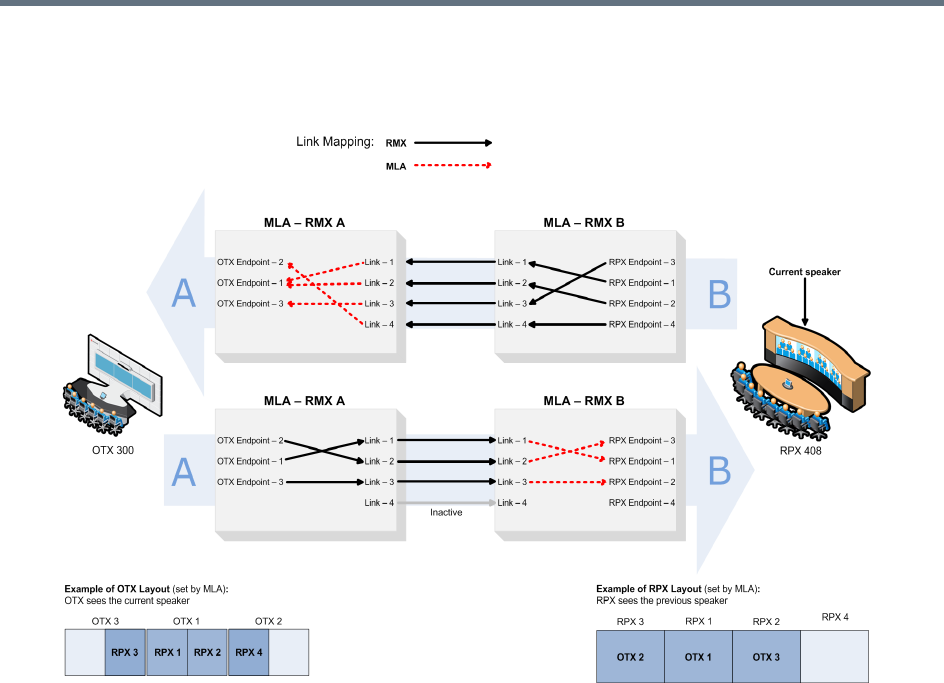
Setting Conferences for Telepresence Mode (AVC CP)
Polycom®, Inc. 182
●Directional media flows, A B, are shown separately for readability purposes.
RMX Telepresence Layout Mode - Room Switch
In the RMX Telepresence Layout Mode - Continuous Presence figure:
An HDX endpoint and an OTX Room System connects to RMX A.
An HDX endpoint and an RPX Room System connects to RMX B.
This layout requires that the Telepresence Layout Mode to be set to Continuous Presence in the
Conference Profiles of the Cascading Conferences in each RMX.
The current speaker is the HDX endpoint connected to RMX A.
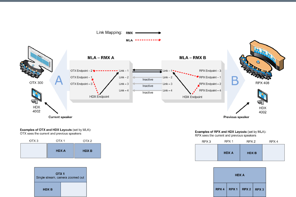
Setting Conferences for Telepresence Mode (AVC CP)
Polycom®, Inc. 183
RMX Telepresence Layout Mode - Continuous Presence
For more information see:
●Setting Conferences for Telepresence Mode (AVC CP).
●Polycom® Multipoint Layout Application (MLA) User’s Guide for Use with Polycom Telepresence
Solutions.
●Polycom® Immersive Telepresence (ITP) Deployment Guide
Creating a Link Participant
Link Participant in the Dial Out RMX
The Link Participant is defined in the New Participant dialog box.
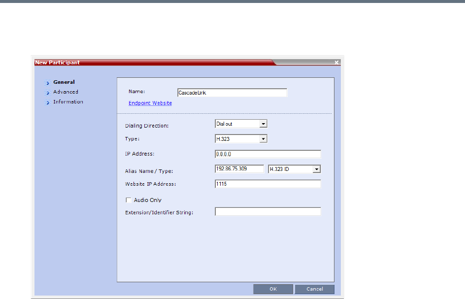
Setting Conferences for Telepresence Mode (AVC CP)
Polycom®, Inc. 184
To create a Link Participant in the dial-out RMX:
1In the General tab:
In the Dialing Direction drop-down menu, select Dial out.
In the Type drop-down menu, select H.323.
For more information see the Creating a Cascade Enabled Dial-out/Dial-in Participant Link.
2In the Advanced tab:
(This field is only enabled if the RMX system is licensed for Telepresence Mode.)
In the Cascade drop-down menu, select either Master or Slave.
In the Number of cascaded links (for ITP) drop-down menu, select the maximum number of
Multiple Cascade Links required according to the number of Room System endpoints in the
cascaded conference.
This field enables the administrator to select the maximum number of Multiple Cascade Links
required according to the number of Room System endpoints in the cascaded conference.
For example if an RPX 4xx is included, the number of links required is 4.
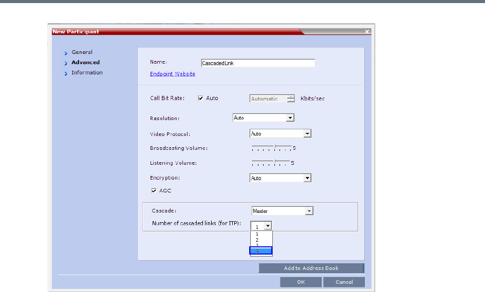
Setting Conferences for Telepresence Mode (AVC CP)
Polycom®, Inc. 185
The RMX automatically adds a number suffix to the name of the Link Participant, for example if
the Participant Link Name is CascadeLink and the Number of cascaded links (for ITP) field
is set to 4, the following Multiple Cascade Links are created:
CascadeLink-1
CascadeLink-2
CascadeLink-3
CascadeLink-4
Participant Link in the Dial In RMX
The call from Participant Link defined in the Dial-out RMX is identified by the Dial-in RMX as having been
initiated by a Participant Link.
Suffixes are appended to the Multiple Cascade Links according to the Number of cascaded links (for ITP)
field depending on whether the Dial -In Participant Link is defined or un-defined:
An Undefined Participant Link
The Multiple Cascade Link names are automatically assigned by the RMX.
For example on a RMX 1500 the names of the links are:
●POLYCOM RMX 1500-1
●POLYCOM RMX 1500-2
●POLYCOM RMX 1500-3, etc.
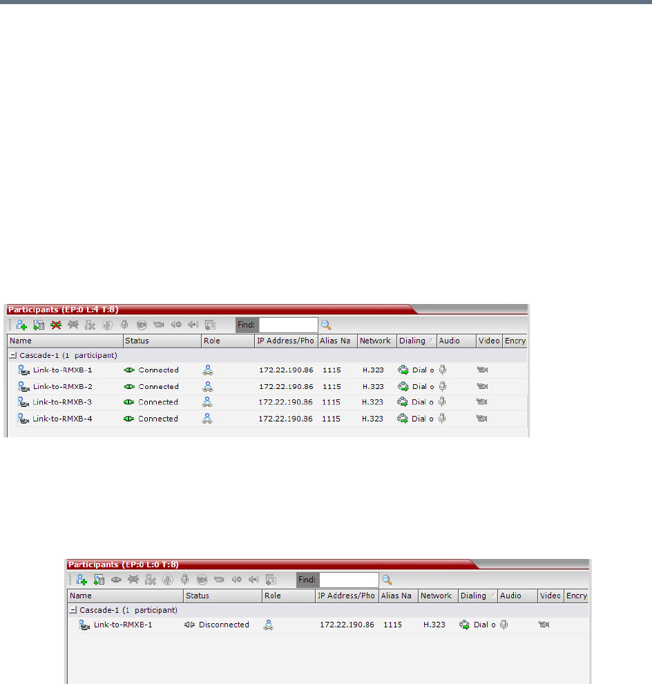
Setting Conferences for Telepresence Mode (AVC CP)
Polycom®, Inc. 186
A Defined Participant Link
The Multiple Cascade Link names are assigned according to the name of the defined participant that is to
function as the cascade link and the Number of cascaded links (for ITP) information sent by the calling
Dial-Out Participant Link.
For example if the defined participant that is to function as the cascade link is named
Cascade_Link_From_B the names of the links are:
●Cascade_Link_From_B-1
●Cascade_Link_From_B-2
●Cascade_Link_From_B-3, etc.
Monitoring Multiple Cascade Links
Multiple Cascade Links connections can be monitored in the Participants list of the RMX Web Client / RMX
Manager main screen:
Disconnection Causes
●If there are insufficient resources to connect all the required links:
None of the links are connected.
The first link is listed as Disconnected in the Participants list of the RMX Web Client / RMX
Manager main screen.
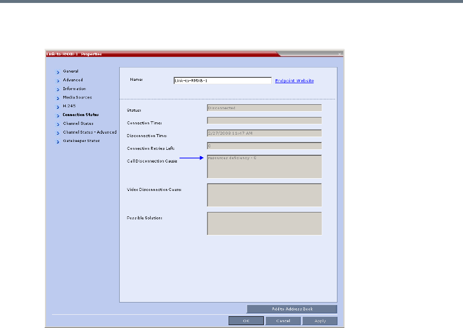
Setting Conferences for Telepresence Mode (AVC CP)
Polycom®, Inc. 187
▪Resource deficiency is listed as the Call Disconnection Cause in the Participant Properties -
Connection Status dialog box.
●If a calling Link Participant is not defined with same number of links as all the other Link Participants
in the cascaded conferences:
The call is rejected.
The Call Disconnection Cause is: Number of cascading links is not identical for
all conferences.

Polycom®, Inc. 188
Additional Conferencing Information
Various conferencing modes and video features require additional settings, such as system flag settings,
conference parameters and other settings. In depth explanations of these additional settings are described
in the following sections:
●Video Preview
●Auto Scan and Customized Polling in Video Layout
●Packet Loss Compensation - LPR and DBA
●Layout Indications
●Lecture Mode
●Audio Algorithm Support
●Automatic Muting of Noisy Endpoints
●Permanent Conference
●Closed Captions
Video Preview
Collaboration Server users can preview the video sent from the participant to the conference (MCU) and the
video sent from the conference to the participant. It enables the Collaboration Server users to monitor the
quality of the video sent and received by the participant and identify possible quality degradation.
The video preview is displayed in a separate window independent to the Collaboration Server Web Client.
All Web Client functionality is enabled and conference and participant monitoring as well as all other user
actions can be performed while the video preview window is open and active. Live video is shown in the
preview window as long as the window is open. The preview window closes automatically when the
conference ends or when participant disconnects from the conference. It can also be closed manually by
the Collaboration Server user.
Video Preview Guidelines
●Video Preview is supported in CP Conferencing Mode only.
●Video preview is available for AVC participants. It is not available for SVC participants.
●Video preview window size and resolution are adjusted to the resolution of the PC that displays the
preview.
●Video Preview of the video sent from the conference to the participant is shown according to the line
rate and video parameters of the level threshold to which the participant is connected.
•Video Preview is applicable for AVC endpoints only.
•Video Preview is not supported when the Collaboration Server is in Ultra Secure Mode. For more
information see Ultra Secure Mode.

Additional Conferencing Information
Polycom®, Inc. 189
●All users can view a video preview.
●Only one preview window can be displayed for each Collaboration Server Web Client connection
(workstation).
●Only one preview window can be displayed for a single conference and up to four preview windows
can be displayed for each media card on different workstations (one per workstation and one per
conference). For example, if the Collaboration Server contains two media cards, and there are 5
conferences running on the Collaboration Server, if five conferences are running on the same media
card, only four conferences can be previewed from four different workstations. If four or less
conferences are running on one media card and the remaining conferences are running on the other
media card, all five conferences can be previewed.
●Live video that is shown in the preview window does not include the Content when it is sent by the
participant.
●Video Preview is supported in cascaded conferences.
●If the video preview window is opened when the IVR slide is displayed to the participant, it will also
be displayed in the video preview window.
●Video Preview is supported with H.264 High Profile.
●Video Preview is not supported for endpoints using the RTV protocol.
●Video Preview is disabled in encrypted conferences.
●Video preview cannot be displayed when the participant’s video is suspended.
●Participant’s video preview and the Polycom Desktop application (such as CMAD) window cannot be
open and running simultaneously on the same PC as both require the same DirectDraw resource.
Workstation Requirements to Display Video Preview
To be able to display the video preview window, the following minimum requirements must be met:
●Windows XP, Windows Vista and Windows 7
●Internet Explorer 7 and later
●DirectX is installed
●DirectDraw Acceleration must be enabled and no other application is using the video resource
●Hardware acceleration must be enabled
Testing your Workstation
To ensure that your workstation can display the video preview window:
1In Windows, click Start > Run.
The Run dialog box opens.
2In the Open field, type dxdiag, and press Enter or click OK.
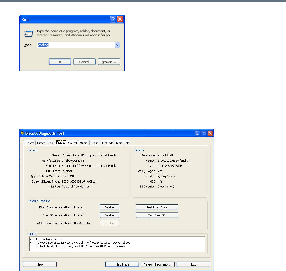
Additional Conferencing Information
Polycom®, Inc. 190
A confirmation message is displayed.
3Click Yes to run the diagnostics.
The DirectX Diagnostic Tool dialog box opens.
4Click the Display tab.
To be able to display the video preview window, the DirectDraw Acceleration and Direct3D
Acceleration options must be Enabled.
If the video card installed in the PC does not support DirectDraw Acceleration, a black window may
be viewed in the Video Preview window.
5Click the Exit button.
Previewing the Participant Video
You can preview the video sent from the participant to the conference (MCU) and the video sent from the
conference to the participant by selecting the appropriate option from the Participant’s pop-up menu.
To preview the participant video:
1List the conference participants in the Participants pane.
2Right-click the participant whose video you want to preview, and select one of the following options:
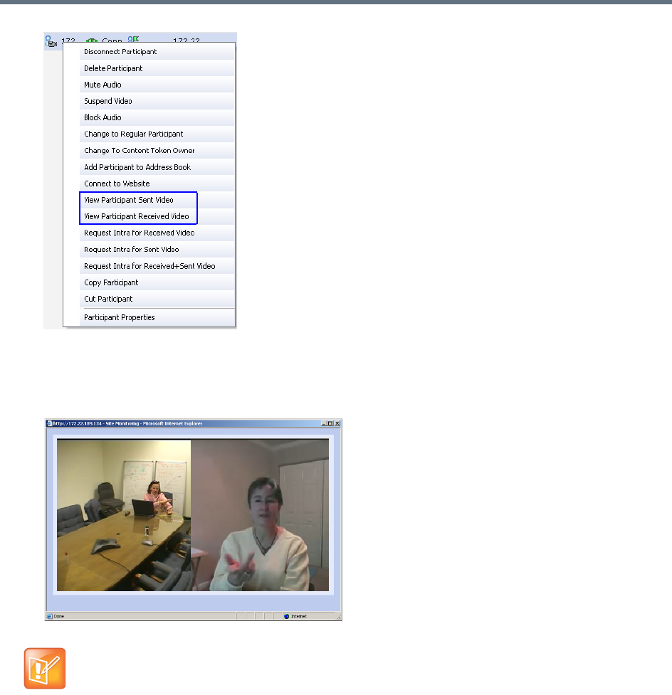
Additional Conferencing Information
Polycom®, Inc. 191
View Participant Sent Video - To display the video sent from the participant to the conference.
View Participant Received Video - To display the video sent from the conference to the
participant.
The Video Preview window opens.
If the video card installed in the PC does not support DirectDraw Acceleration, a black window may
be viewed.

Additional Conferencing Information
Polycom®, Inc. 192
Auto Scan and Customized Polling in Video Layout
Auto Scan enables you to define a single cell in the conference layout to cycle the display of participants
that are not in the conference layout.
Customized Polling allows the cyclic display to be set to a predefined order for a predefined time period.
The cyclic display only occurs when the number of participants is larger than the number of cells in the
layout.
Guidelines for Using Auto Scan and Customized Polling
●Auto Scan and Customized Polling are supported in AVC CP conferences only.
●Participants that are in the conference layout will not appear in the Auto Scan enabled cell.
●If Customized Polling is not used to define the order of the Auto Scan it will proceed according to order
in which the participants connected to the conference.
●If the user changes the conference layout, the Auto Scan settings are not exported to the new layout.
If the user changes the conference layout back to the layout in which Auto Scan was enabled, Auto
Scan with the previous settings will be resumed.
Enabling the Auto Scan and Customized Polling
Auto Scan and Customized Polling are enabled during the ongoing conference, in the Conference
Properties - Video Settings dialog box.
Enabling the Auto Scan
You enable the Auto Scan feature by selecting it in the Video Layout cell.
To enable Auto Scan:
1In the Collaboration Server Web Client Main Screen - Conference list pane, double-click the
conference or right-click the conference and then click Conference Properties.
Auto scan and customized polling in video layout is applicable for AP conferencing only.
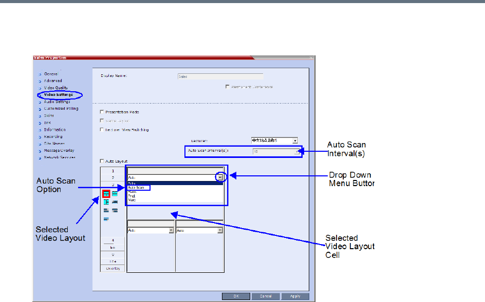
Additional Conferencing Information
Polycom®, Inc. 193
2In the Conference Properties - General dialog box, click Video Settings.
The Video Settings dialog box is displayed.
3If Auto Layout check box is selected, clear it.
4In the video layout cell to be designated for Auto Scan, select from the drop-down menu Auto Scan.
5Select from the Auto Scan Interval(s) list the scanning interval in seconds.
6Click the Apply button to confirm and keep the dialog box open, or Click OK.
Customized Polling
The order in which the Auto Scanned participants are displayed in the Auto Scan enabled cell of the video
layout can be customized.
To define the scanning order in the Customized Polling tab:
1Open the Conference Properties dialog box.
2Click the Customized Polling tab.
The Customized Polling dialog box is displayed.
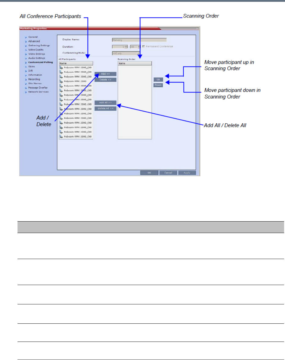
Additional Conferencing Information
Polycom®, Inc. 194
All conference participants are listed in the left pane (All Participants) whereas the participants to be
displayed in the Auto Scan enabled cell are listed in the right pane (Scanning Order).
The dialog box buttons are summarized in the following table:
3Click the Apply button to confirm and keep the dialog box open, or click OK.
Customized Polling Dialog Box Command Buttons
Button Description
Add Select a participant and click this button to add the participant to the list of
participants to be Auto Scanned.
The participants name is removed from the All Participants pane.
Delete Select a participant and click this button to delete the participant from the list
of participants to be Auto Scanned.
The participants name is moved back to the All Participants pane.
Add All Add all participants to the list of participants to be Auto Scanned.
All participants’ names are removed from the All Participants pane.
Delete All Delete all participants from the list of participants to be Auto Scanned.
All participants’ names are moved back to the All Participants pane.
Up Select a participant and click this button to move the participant up in the
Scanning Order.
Down Select a participant and click this button to move the participant down in the
Scanning Order.

Additional Conferencing Information
Polycom®, Inc. 195
Packet Loss Compensation - LPR and DBA
Lost Packet Recovery (LPR) and Dynamic Bandwidth Allocation (DBA) help minimize media quality
degradation that can result from packet loss in the network. Packet loss Compensation is available in AVC
CP Conferencing Mode only and is not supported in SVC Conferencing Mode or CP and SVC Conferencing
Mode.
Packet Loss
Packet Loss refers to the failure of data packets, transmitted over an IP network, to arrive at their
destination. Packet Loss is described as a percentage of the total packets transmitted.
Causes of Packet Loss
Network congestion within a LAN or WAN, faulty or incorrectly configured network equipment or faulty
cabling are among the many causes of Packet Loss.
Effects of Packet Loss on Conferences
Packet Loss affects the quality of:
●Video – frozen images, decreased frame rate, flickering, tiling, distortion, smearing, loss of lip sync
●Audio – drop-outs, chirping, audio distortion
●Content – frozen images, blurring, distortion, slow screen refresh rate
Lost Packet Recovery
The Lost Packet Recovery (LPR) algorithm uses Forward Error Correction (FEC) to create additional
packets that contain recovery information. These additional packets are used to reconstruct packets that are
lost, for whatever reason, during transmission. Dynamic Bandwidth Allocation (DBA) is used to allocate the
bandwidth needed to transmit the additional packets.
Lost Packet Recovery Guidelines
●If packet loss is detected in the packet transmissions of either the video or Content streams:
LPR is applied to both the video and Content streams.
DBA allocates bandwidth from the video stream for the insertion of additional packets containing
recovery information.
●Due to the LPR increasing the required bandwidth, content rate might be reduced (to no less than
64K) to preserve it.
When this reduction is insufficient, either the video rate or the LPR strength are reduced as well,
depending on the value of the system flag LPR_CONTENT_RATE_ADJUST_WEAK_LPR. For more
information on that flag see LPR_CONTENT_RATE_ADJUST_WEAK_LPR.
LPR and DBA are applicable for AVC conferencing only.

Additional Conferencing Information
Polycom®, Inc. 196
●LPR is supported in H.323 and SIP networking environments only.
●In LPR-enabled Continuous Presence conferences:
Both LPR-enabled and non-LPR-enabled endpoints are supported.
The LPR process is not applied to packet transmissions from non-LPR-enabled IP (H.323 and
SIP) and ISDN endpoints.
Non-LPR-enabled endpoints can be moved to LPR-enabled conferences.
LPR-enabled endpoints cannot be moved to non-LPR-enabled conferences.
●In LPR-enabled Video Switched conferences:
H.323 and SIP endpoints are supported.
When cascading between conferences running on Collaboration Server and MGC (Polycom
legacy MCU), LPR is not supported over the link between the two conferences.
Non-H.323 participants cannot be created, added or moved to LPR-enabled Video Switched
conferences.
●When connecting via an Entry Queue:
A participant using an LPR-enabled endpoint can be moved to a non-LPR-enabled conference.
The participant is connected with LPR enabled.
SIP and ISDN/PSTN participants cannot be moved to LPR-enabled Video Switched conferences.
Enabling Lost Packet Recovery
LPR is enabled or disabled in the Conference Profile dialog box.
●CP Conferences – LPR is enabled by default in the New Profile – Advanced dialog box.
●VSW Conferences – If Video Switching is selected, the LPR check box is automatically cleared and
LPR is disabled. LPR can be enabled for VSW conferences but H.320 and SIP participants will not
be able to connect.
For more information, see Defining New Profiles.
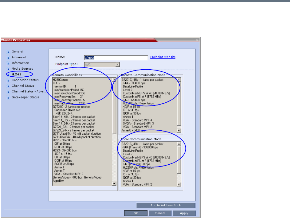
Additional Conferencing Information
Polycom®, Inc. 197
Monitoring Lost Packet Recovery
In the Participant Properties – H.245 tab, LPR activity is displayed in all three panes.
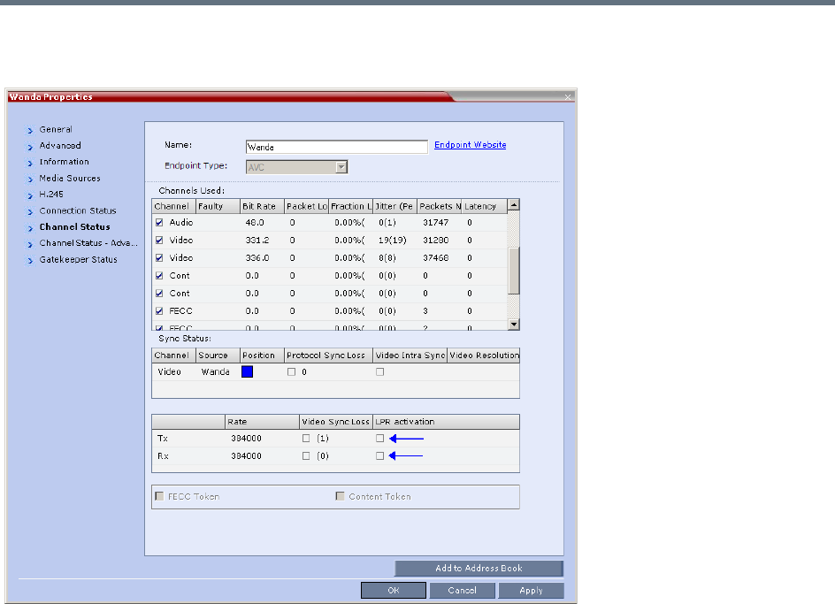
Additional Conferencing Information
Polycom®, Inc. 198
In the Participant Properties – Channel Status tab, check box indicators show LPR activation in the local
and remote (transmit and receive) channels.
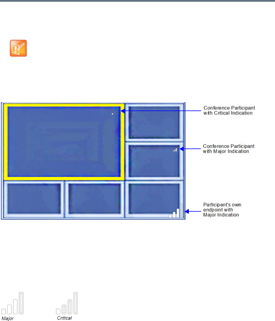
Additional Conferencing Information
Polycom®, Inc. 199
Layout Indications
Network Quality Indication
If network quality issues occur, the Network Quality icon provide information to participants about their own
network quality and that of other participants displayed in the cells of the conference Video Layout.
Network Quality Levels
Network quality is determined by the percentage of packet loss according to the following default threshold
values:
●Packet loss less than 1% is considered Normal
●Packet loss in the range of 1% - 5% is considered Major
●Packet loss above 5% is considered Critical.
Major and Critical states are indicated by the following icons:
When network quality improves from Critical to Major remaining stable for 5 seconds, the Network Quality
Indicator is changed accordingly and when network quality improves from Major to Normal, remaining stable
for 5 seconds, the Network Quality Indicator is no longer displayed.
Layout Indications are applicable to AVC endpoints only.
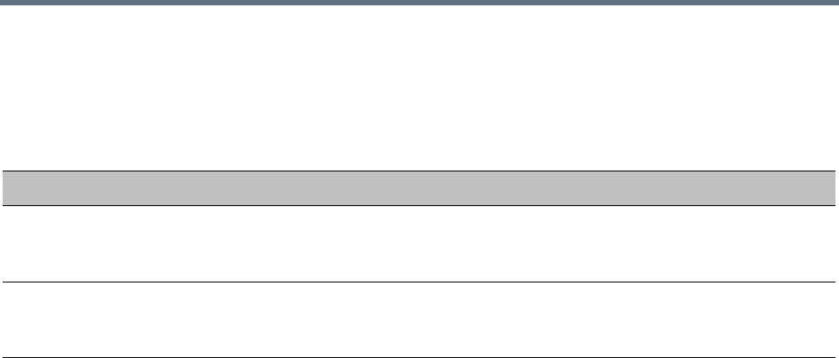
Additional Conferencing Information
Polycom®, Inc. 200
Indication Threshold Values
The default Major and Critical indication threshold values can be modified by manually adding the following
System Flags and modifying their values as required.
For more information see .
Displaying the Network Quality icons
Network Quality icons are not supported in SVC Conferencing Mode and AVC - Video switched
conferences.
Network Quality icons are displayed for:
●The video channel only in AVC Conferencing Mode.
Content, audio and FECC channel quality issues are not indicated.
●The participant’s own endpoint:
Network Quality icons are displayed by default and can be disabled
For media transmitted to and received from the Collaboration Server (Video in / Video out).
●Participants displayed in the cells of the conference video layout:
Network Quality icons are not displayed by default and can be enabled
The media transmitted from the endpoint to the Collaboration Server (Video in).
Customizing the Network Quality Icon Display
Display of the Network Quality icon can be customized for the participant’s own endpoint or for the
Participants displayed in the cells of the conference Video Layout.
The display of Network Quality icon (showing or hiding the icon) and the position of the icon in the video
layout cell can be customized by manually adding the following System Flags and modifying their values as
required.
Network Quality Icon - Indication Threshold Flags
Flag Description
NETWORK_IND_MAJOR_PERCENTAGE The percentage degradation due to packet loss required to
change the indicator from Normal to Major.
Default: 1
NETWORK_IND_CRITICAL_PERCENTAGE The percentage degradation due to packet loss required to
change the indicator from Major to Critical.
Default: 5

Additional Conferencing Information
Polycom®, Inc. 201
For more information see the .
Network Quality Icon - Display Customization Flags
Flag Description
DISABLE_SELF_NETWORK_IND Disable the display of the Network Quality icon of the
participant’s own endpoint.
Default: NO
Range: YES / NO
NOTE: This flag’s function has been replaced by the
Network Quality check box in the Layout Indications tab of
the New Profile / Profile Properties dialog.
For more information see New AVC CP Profile - Layout
Indications Parameters.
DISABLE_CELLS_NETWORK_IND Disable the display of Network Quality icons displayed in
the cells of the conference Video Layout.
Default: YES
Range: YES / NO
SELF_IND_LOCATION Change the location of the display of the Network Quality
icon of the participant’s own endpoint.
Default: BOTTOM_RIGHT
Range:
•TOP_ LEFT
•TOP
• TOP_RIGHT
•BOTTOM_ LEFT
•BOTTOM
•BOTTOM_RIGHT
NOTE: This flag’s function has been replaced by the
Network Quality check box in the Layout Indications tab of
the New Profile or Profile Properties dialog.
For more information see New AVC CP Profile - Layout
Indications Parameters.
CELL_IND_LOCATION Change the location of the display of Network Quality icon
displayed in the cells of the conference Video Layout.
Default: TOP_RIGHT
Range:
•BOTTOM_LEFT
•BOTTOM_RIGHT
•TOP_LEFT
• TOP_RIGHT
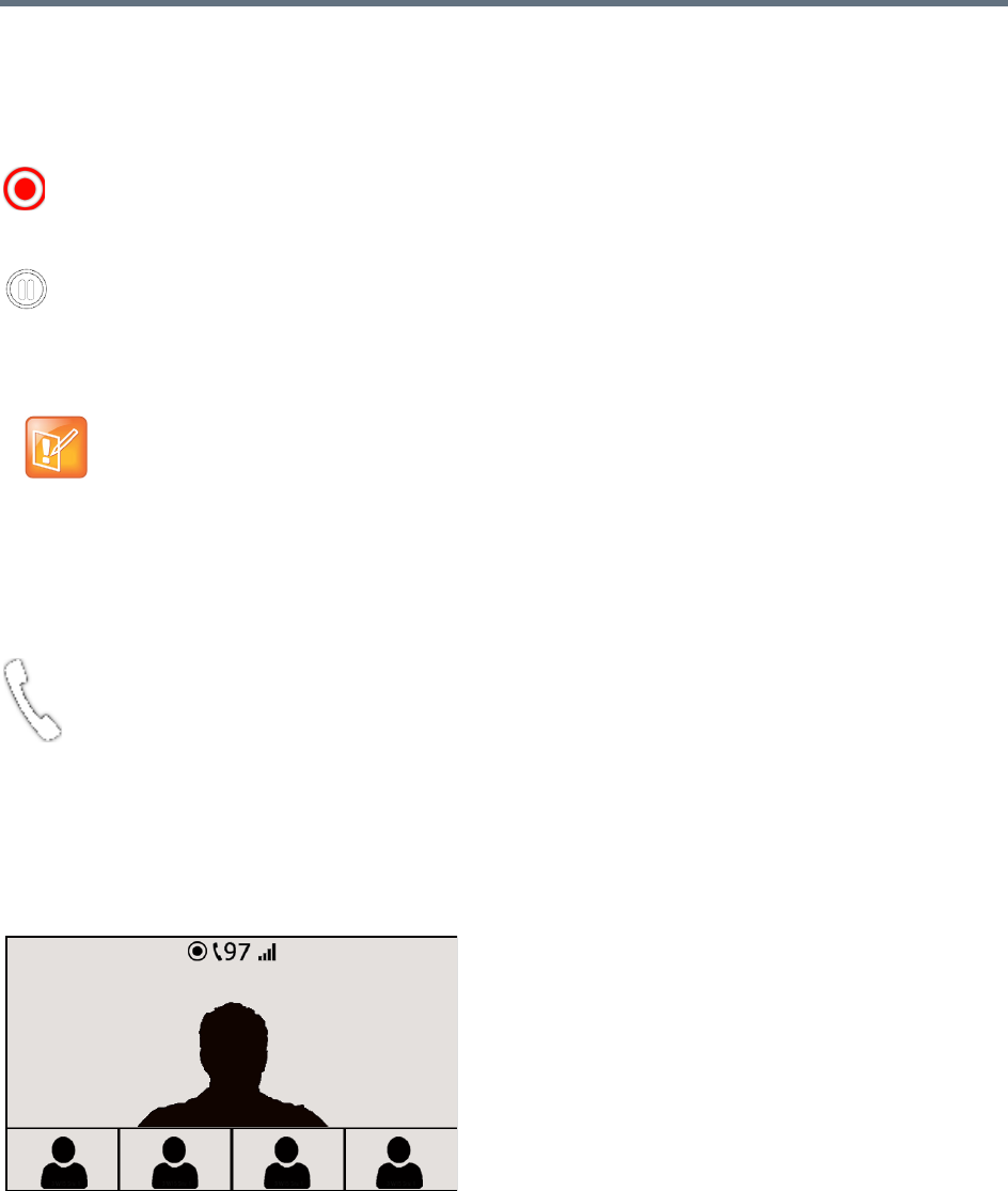
Additional Conferencing Information
Polycom®, Inc. 202
Recording Indications
When Display Recording Icon is selected in either the Recording or Layout Indications tab of the New
Profile or Profile Properties dialog, the recording status is indicated by the following icons:
Audio Participants Indication
During an ongoing conference, Audio Participants Indication icon provides an indication to all participants
that audio-only endpoints and secondary video devices are connected to the conference.
The Audio Participant indication icon is displayed in the conference video screen along with the number of
audio-only or secondary endpoints connected. These icons are displayed as part of a group that includes a
network quality indication and a recording indication displayed when recording is active. The icon group is
displayed for AVC endpoints only.
The following figure shows that 97 audio participants are connected to the current conference.
The following conferencing modes are supported:
●AVC-CP (Continuous Presence)
●CP and SVC (Mixed Mode).
Recording
For more information, see
Recording and Streaming Conferences
and New AVC CP Profile
- Layout Indications Parameters.
Recording Paused
For more information, see
Recording and Streaming Conferences
and New AVC CP Profile
- Layout Indications Parameters.
The Recording Indication icon is a duplicate of the Display Recording icon of the Recording tab of the
Profile dialog. For more information, see
Recording and Streaming Conferences
and New AVC CP
Profile - Layout Indications Parameters.
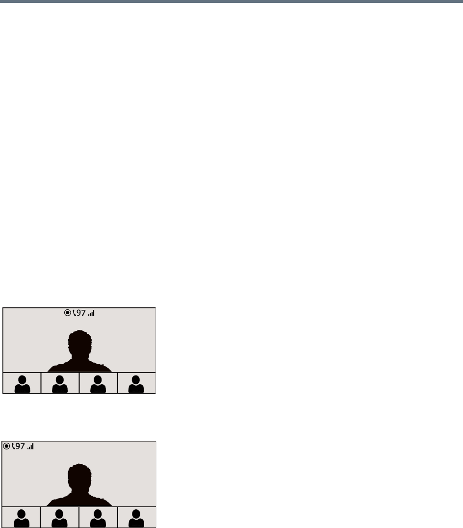
Additional Conferencing Information
Polycom®, Inc. 203
●Up to 99 audio participants can be indicated; when more than 99 participants are in the conference,
the indicator shows 99+.
●You can set audio participant indication to display permanently or for a short period only when the
number of audio participants changes. When audio participant indication is set to display
permanently, it is displayed only when audio participants are connected to the conference.
●The position of the icon can be customized.
Audio participant indication is not supported in the following circumstances:
●In TIP-enabled conferences
●In SVC only and AVC-VSW (Video Switched) conferencing modes
●For remote audio participants in cascading conferences; only the number of audio participants
connected to the local MCU is displayed
●On SVC endpoints
●During the gathering phase of a conference
●At video resolutions lower than 4CIF
Layout Indications Icon Display Positions
Following are examples of the Indication Icons display positions (97 audio participants are connected to the
conference).
Top-center (default) with all indication icons enabled
Top-left, with all indication icons enabled
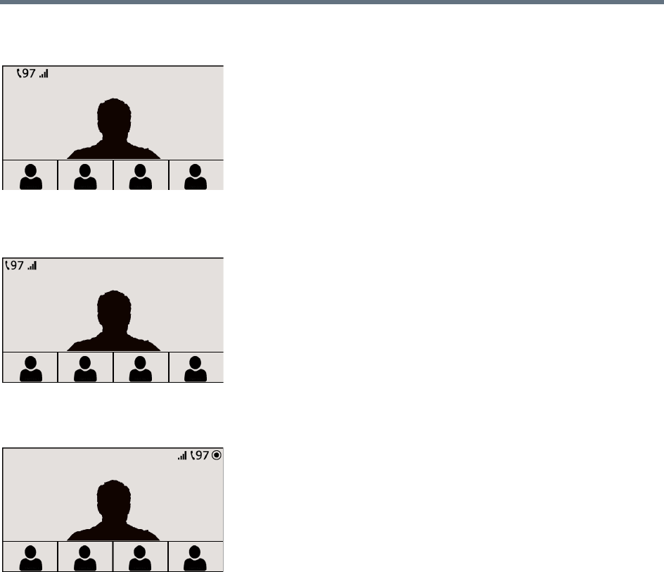
Additional Conferencing Information
Polycom®, Inc. 204
Top-left, with all indication icons enabled, recording enabled but not active
Top-left, audio participants, network quality enabled, recording not enabled
Top-right with all indication icons enabled, recording active
Conferences launched using Profiles that were defined in versions that do not include the Layout Indications
tab will behave as if all the parameters in the tab are unchecked.
To display indications according to the local endpoint’s capability (4CIF and up), Collaboration Servers
1500/2000/4000) should disable the system’s 1x1 layout functionality that includes sending the current
speaker’s resolution.
For example, in a conference between two video endpoints the layout is 1x1 by default. If the resolution of
one of the endpoints is lower than 4CIF and the other higher than 4CIF, the RealPresence Collaboration
Servers 1500/2000/4000 will follow the speaker and not transmit the Indication Icons when the lower
resolution endpoint is the active speaker. (RealPresence Collaboration Servers 1800 never follow the
speaker.) As a result, the endpoint capable of higher resolution will not receive the Indication Icons.
For further details on how to determine the layout indications position, see New AVC CP Profile - Layout
Indications Parameters.
This behavior can be modified by manually adding the
HW_FOLLOW_SPEAKER_RESOLUTION_ON_1X1_LAYOUT flag to the System Configuration and
modifying its value.

Additional Conferencing Information
Polycom®, Inc. 205
The flag values may be modified as follows:
●AUTO (Default) - When any of the Indication Icons are configured for display, do not follow the
speaker. When the Indication Icons are not configured for display, follow the speaker.
●YES - Always follow the speaker in 1x1 layout.
●NO - Never follow the speaker in 1x1 layout.
For more information, see Modifying System Flags.
Lecture Mode
(
Lecture Mode enables all participants to view the lecturer in full screen while the conference lecturer sees
all the other conference participants in the selected layout while he/she is speaking. When the number of
sites/endpoints exceeds the number of video windows in the layout, switching between participants occurs
every 15 seconds. Conference participants cannot change their Personal Layouts while Lecture Mode is
enabled.
Automatic switching is suspended when one of the participants begins talking, and it is resumed
automatically when the lecturer resumes talking.
Lecture Mode is available only in AVC CP Conferencing Mode.
Enabling Lecture Mode
Lecture Mode is enabled at the conference level by selecting the lecturer. Conference participants cannot
change their Personal Layouts while Lecture Mode is enabled.
Automatic switching between participants viewed on the lecturer’s screen is enabled in the conference
Profile.
Selecting the Conference Lecturer
Selecting a lecturer for the ongoing conference, enables the Lecture Mode. You can select the lecturer:
●during the definition of the ongoing conference
●after the conference has started and the participants have connected to the conference.
Lecture mode is applicable for AVC CP conferencing only.
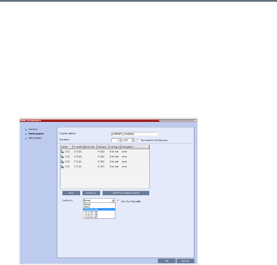
Additional Conferencing Information
Polycom®, Inc. 206
To select the lecturer and enable the Lecture Mode while starting the conference:
»In the Conference Properties - Participant dialog box, enable the Lecture Mode using one of the
following methods:
To automatically select a defined participant:
1Add participants to the conference either from the Address book or by defining new participants.
2In the Lecturer field, select the lecturer from the list of the defined participants.
To automatically select the lecturer:
»In the Lecturer field, select [Auto].
In this mode, the conference speaker becomes the lecturer.
To select the lecturer and enable the Lecture Mode during the ongoing conference:
1Make sure that the participant you want to designate as the lecturer has connected to the
conference.
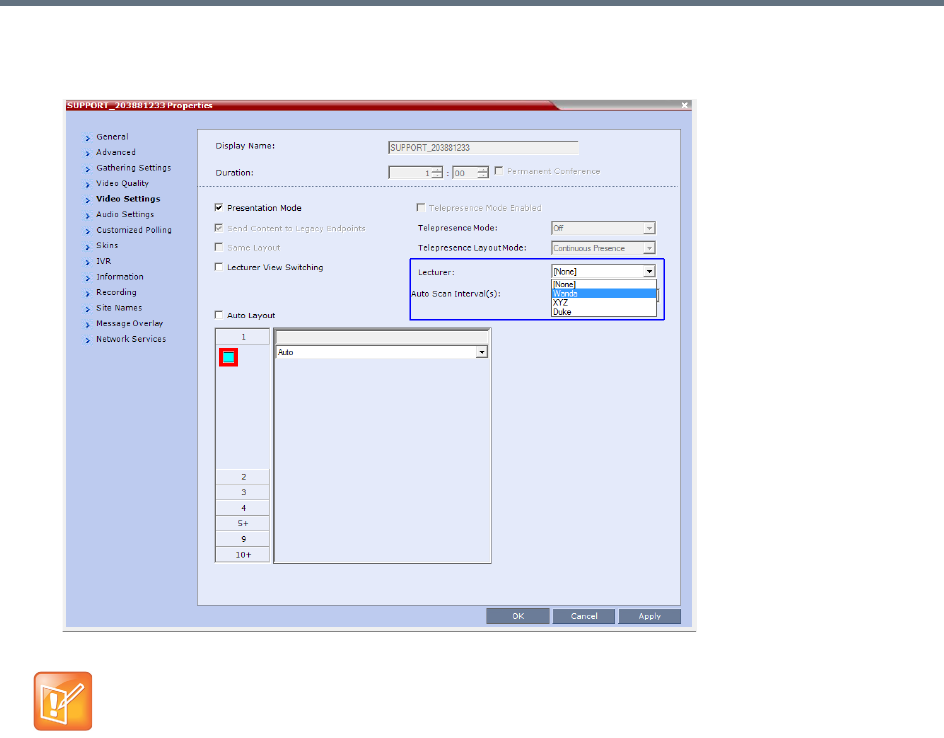
Additional Conferencing Information
Polycom®, Inc. 207
2In the Conference Properties - Video Settings dialog box, in the Lecturer field, select the lecturer
from the list of the connected participants.
Enabling the Automatic Switching
Automatic switching between participants viewed on the lecturer’s screen is enabled in the conference
Profile, or during the ongoing conference, in the Conference Properties.
Defined dial out participants and dial in participants are considered to be two separate participants
even if they have the same IP address/number. Therefore, if a defined dial-out participant is added to
the conference and the same participant then dials in (before the system dialed out to that
participant) the system creates a second participant in the Participants list and tries to call the
dial-out participant. If the dial-out participant was designated as the conference lecturer, the system
will not be able to replace that participant with the dial-in participant that is connected to the
conference.
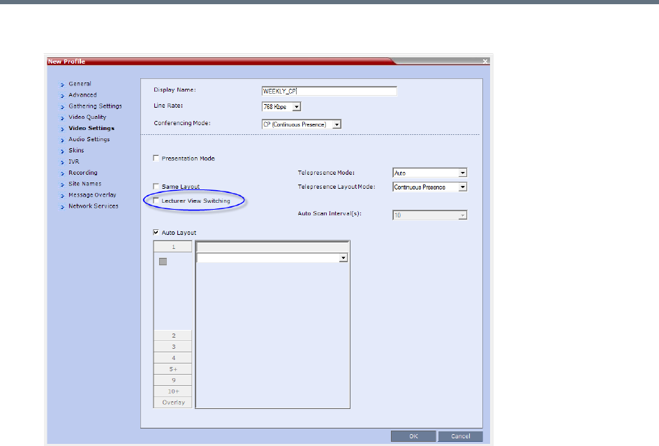
Additional Conferencing Information
Polycom®, Inc. 208
●In the Profile Properties - Video Settings tab, select the Lecturer View Switching check box.
This option is activated when the conference includes more sites than windows in the selected layout.
If this option is disabled, the participants will be displayed in the selected video layout without
switching.
For more information about Profile definition, see Defining AVC-Based Conference Profiles.
●Once the conference is running, in the Conference Properties - Video Settings dialog box, select
the Lecturer View Switching check box.
Lecture Mode Monitoring
A conference in which the Lecture Mode is enabled is started as any other conference. The conference runs
as an audio activated Continuous Presence conference until the lecturer connects to the conference. The
selected video layout is the one that is activated when the conference starts. Once the lecturer is connected,
the conference switches to the Lecture Mode.
When Lecturer View Switching is activated, it enables automatic switching between the conference
participants in the lecturer’s video window. The switching in this mode is not determined by voice activation
and is initiated when the number of participants exceeds the number of windows in the selected video
layout. In this case, when the switching is performed, the system refreshes the display and replaces the last
active speaker with the current speaker.
When one of the participants is talking, the automatic switching is suspended, showing the current speaker,
and it is resumed when the lecturer resumes talking.
If the lecturer is disconnected during an Ongoing Conference, the conference resumes standard
conferencing.
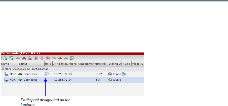
Additional Conferencing Information
Polycom®, Inc. 209
Forcing is enabled at the Conference level only. It applies only to the video layout viewed by the lecturer as
all the other conference participants see only the lecturer in full screen.
If an asymmetrical video layout is selected for the lecturer (i.e. 3+1, 4+1, 8+1), each video window contains
a different participant (i.e. one cannot be forced to a large frame and to a small frame simultaneously).
When Lecture Mode is enabled for the conference, the lecturer is indicated by an icon in the Role column
of the Participants list.
To control the Lecture Mode during an Ongoing Conference:
1During the Ongoing Conference, in the Conference Properties - Video Settings dialog box you
can:
Enable or disable the Lecture Mode and designate the conference lecturer in the Lecturer list;
select None to disable the Lecture Mode or select a participant to become the lecturer to enable it.
Designate a new lecturer.
Enable or disable the Lecturer View Switching between participants displayed on the lecturer
monitor by selecting or clearing the Lecturer View Switching check box.
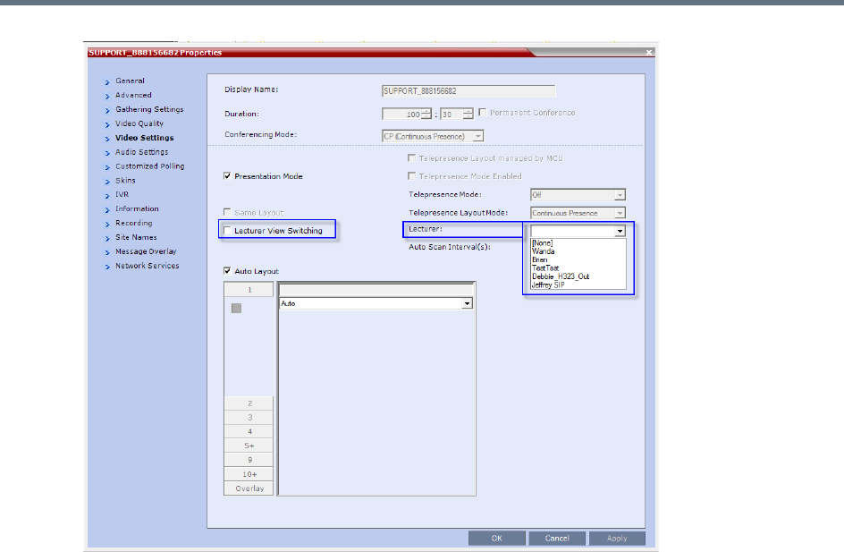
Additional Conferencing Information
Polycom®, Inc. 210
Change the video layout for the lecturer by selecting another video layout.
Restricting Content Broadcast to Lecturer
Content broadcasting can be restricted to the conference lecturer only, when one of the conference
participants is set as the lecturer (and not automatically selected by the system). Restricting the Content
Broadcast prevents the accidental interruption or termination of H.239 Content that is being shared in a
conference.
Content Broadcast restriction is enabled by setting the
RESTRICT_CONTENT_BROADCAST_TO_LECTURER system flag to ON. When set to OFF (default) it
enables all users to send Content.
When enabled, the following rules apply:
●Content can only be sent by the designated lecturer. When any other participant tries to send Content,
the request is rejected.
●If the Collaboration Server user changes the designated lecturer (in the Conference Properties -
Video Settings dialog box), the Content of the current lecturer is stopped immediately and cannot be
renewed.
●The Collaboration Server User can abort the H.239 Session of the lecturer.
●Content Broadcasting is not implemented in conferences that do not include a designated lecturer
and the lecturer is automatically selected by the system (for example, in Presentation Mode).

Additional Conferencing Information
Polycom®, Inc. 211
Muting Participants Except the Lecturer
When the Mute Participants Except Lecturer option in the Conference Profile is enabled, the audio of all
participants in the conference except for the lecturer can be automatically muted upon connection to the
conference. This prevents other conference participants from accidentally interrupting the lecture, or from a
noisy participant affecting the audio quality of the entire conference. Muted participants cannot unmute
themselves unless they are unmuted from the Collaboration Server Web Client/RMX Manager.
Guidelines for Muting all the Participants Except the Lecturer
●Both administrators and operators (users) are allowed to set the Mute Participants Except Lecturer
option.
●When the Mute Participants Except Lecturer option is enabled, the mute indicator on the participant
endpoints are not visible because the mute participants was initiated by the MCU. Therefore, it is
recommended to inform the participants that their audio is muted by using the Message Overlay
functions.
●When the Mute Participants Except Lecturer option is enabled in the Conference Profile settings, all
conferences to which this profile is assigned will start with this option enabled. All participants, except
for the designated lecturer, are muted.
●The Mute Participants Except Lecturer option can be enabled or disabled at any time after the start
of the conference. When enabled, it allows all the conference participants to converse before the
lecturer joins the conference or before they are muted. When disabled, it unmutes all the participants
in the conference.
●If the endpoint of the designated lecturer is muted when the lecturer connects to the conference, the
lecturer remains muted until the endpoint has been unmuted.
●When you replace a lecturer, the MCU automatically mutes the previous lecturer and unmutes the
new lecturer.
●When you disconnect a lecturer from the conference or the lecturer leaves the conference, all
participants remain muted but are able to view participants in regular video layout until the you disable
the Mute Participants Except Lecturer option.
●A participant can override the Mute Participants Except Lecturer option by activating the Mute All
Except Me option using the appropriate DTMF code, provided the participant has authorization for
this operation in the IVR Services properties. The lecturer audio is muted and the participant audio is
unmuted. You can reactivate the Mute Participants Except Lecturer option after a participant has
previously activated the Mute All Except Me option. The participant is muted and the lecturer, if
designated, is unmuted.
●In cascaded conferences, all participants (including the link participants) except the lecturer are
muted. Only the lecturer is not muted.
Muting participant except the lecturer is possible in AVC CP conferencing only.
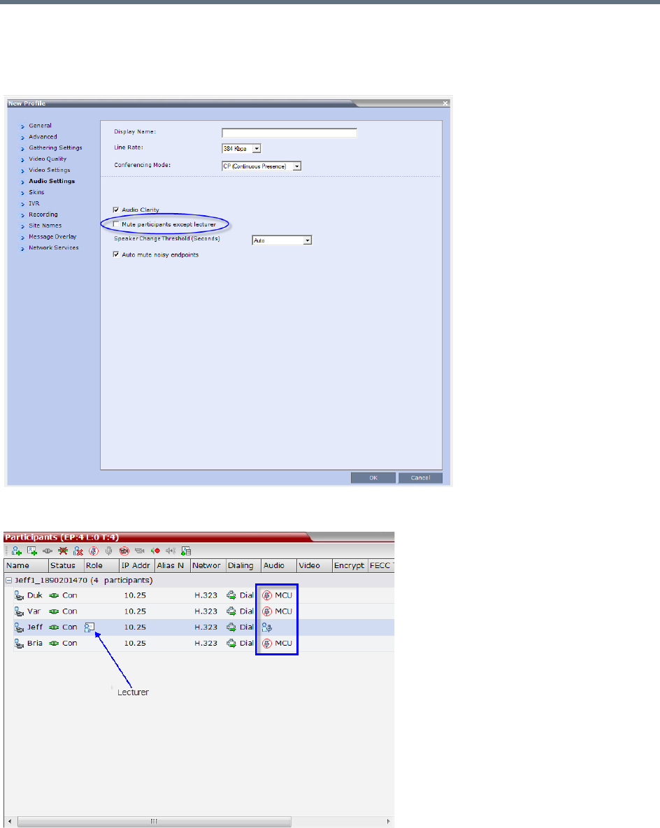
Additional Conferencing Information
Polycom®, Inc. 212
Enabling the Mute Participants Except Lecturer Option
The Mute Participants Except Lecturer option is enabled or disabled (default) in the Conference Profile or
in an ongoing conference in the Profile Properties - Audio Settings tab.
When the Mute Participants Except Lecturer option is enabled and a conference has started, the Mute by
MCU icon is displayed in the Audio column in the Participants pane of each participant that is muted.

Additional Conferencing Information
Polycom®, Inc. 213
Audio Algorithm Support
The Collaboration Server supports the following audio algorithms in AVC conferences: G.711, G.722,
G.722.1, G.722.1C, G.729A, G.719, G. 728, G.723.1, siren 7, Siren14, Siren 22 (in mono or stereo) and
SirenLPR.
Polycom’s proprietary Siren 22 and industry standard G.719 audio algorithms are is supported for
participants connecting with Polycom endpoints.
The Siren 22 audio algorithm provides CD-quality audio for better clarity and less listener fatigue with audio
and visual communication applications. Siren 22 requires less computing power and has much lower
latency than alternative wideband audio technologies.
The Siren 7 audio codec is the preferred codec for SIP/Lync calls, depending on the value of the system
flag ALLOW_SIREN7_CODEC. This preference is aimed at preventing disconnection of Lync clients using
audio rates smaller than 42Kbps, when the Lync server is configured to allow 33Kbps audio rate. For more
information see ALLOW_SIREN7_CODEC.
The SirenLPR audio algorithm provides CD-quality audio for better clarity and less listener fatigue with audio
and visual communication applications.
In SVC conferences, the system supports SAC (Scalable Audio Coding) audio algorithm.
Audio Algorithm Support Guidelines
●Siren 22 and G.719 are supported in both mono and stereo.
●Stereo is supported in H.323 calls only.
●Siren 22 is supported by Polycom HDX and Group series endpoints, version 2.0 and later.
●Siren 7 is the preferred audio codec for SIP/Lync clients, provided the system flag
ALLOW_SIREN7_CODEC is set to YES.
●G.728 is supported in H.323, SIP and ISDN environments.
●SirenLPR is enabled by default and can be disabled by setting the system flag ENABLE_SIRENLPR,
to NO.
●SirenLPR is supported:
In IP (H.323, SIP) calls only.
In CP and VSW conferences.
With Polycom CMAD and HDX 3.0.1 and later and Group series endpoints.
For mono audio at audio line rates of 32Kbps, 48Kbps and 64Kbps.
For stereo audio at audio line rates of 64Kbps, 96Kbps and 128Kbps.
SIP Encryption
The ENABLE_SIRENLPR_SIP_ENCRYPTION System Flag enables the SirenLPR audio algorithm when
using encryption with the SIP protocol.
The default value of this flag is NO meaning SirenLPR is disabled by default for SIP participants in an
encrypted conference. To enable SirenLPR the System Flag must be added to system.cfg and its value set
to YES.

Additional Conferencing Information
Polycom®, Inc. 214
Mono
The Siren 22, G.719, and SirenLPR mono audio algorithms are supported at the following bit rates.
:
Siren22, G.719, and SirenLPR Mono vs Bitrate
Audio Algorithm Minimum Bitrate (kbps)
Siren22 64k
Siren22 48K
Siren22_32k
G.719_64k 384
G.719_48k
G.719_32k
G.728 16K
G.719_64k 384
SirenLPR_48k 256
Siren22_48K
G.719_48k
G.7221C_48k
Siren14_48k
SirenLPR_32k
128
Siren22_32k
G.719_32k
G.7221C_32k
Siren14_32k
SirenLPR 64
SirenLPR 48
SirenLPR 32
Siren7 16
Additional Conferencing Information
Polycom®, Inc. 215
Stereo
The Siren 22Stereo, G.719Stereo, and SirenLPR audio algorithms are supported at the following bit rates.
Audio algorithms supported for ISDN
Siren22Stereo, G.719Stereo, and SirenLPR vs Bitrate
Audio Algorithm Minimum Bitrate (kbps)
Siren22Stereo_128k
1024SirenLPRStereo_128k
G.719Stereo_128k
Siren22Stereo_96k
512
SirenLPRStereo_96k
G.719Stero_96k
Siren14Stero_96k
SirenLPRStereo_64k
384
G.719Stereo_64k
Siren22Stereo_64k
Siren14Stereo_64k
Supported Audio Algorithm vs Bitrate
Audio Algorithm Minimum Bitrate (kbps)
G.722.1C 48K
256
G.722.1C 32K
G.722.1C 24K
Siren14 48K
Siren14 32K
Siren14 24K
G.722.1 32K
G.722.1 24K

Additional Conferencing Information
Polycom®, Inc. 216
G.722.1 16K
256
G.722 48K
G.722 56K
G.722 64K
G.711 56K
G.711 64K
G.728 16K
G.722.1C 32K
128
G.722.1C 24K
Siren14 32K
Siren14 24K
G.722.1 32K
G.722.1 24K
G.722 48K
G.722 56K
G.722 64K
G.711 56K
G.711 64K
G.728 16K
G.722.1 16K
96
G.722.1C 24K
Siren14 24K
G.722 48K
G.722 56K
G.722 64K
G.711 56K
G.711 64K
G.728 16K
G.728 16K 64
Supported Audio Algorithm vs Bitrate
Audio Algorithm Minimum Bitrate (kbps)
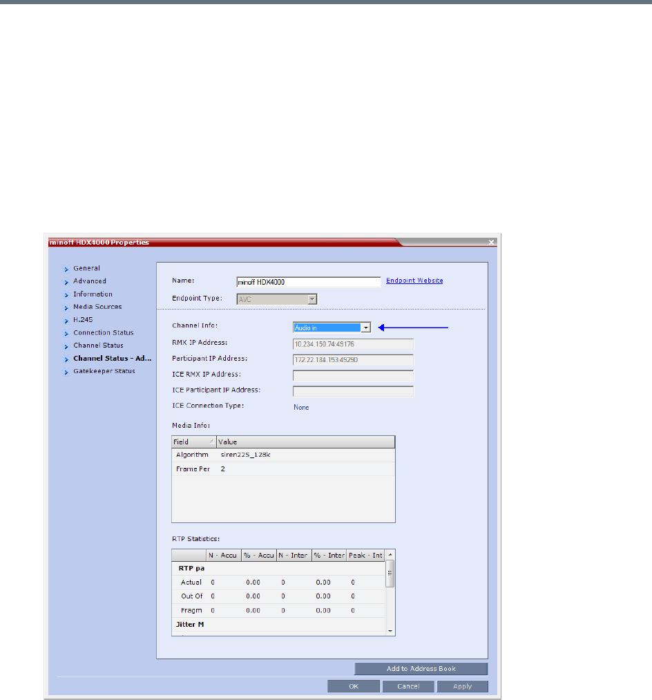
Additional Conferencing Information
Polycom®, Inc. 217
Monitoring Participant Audio Properties
The audio algorithm used by the participant’s endpoint can be verified in the Participant Properties -
Channel Status dialog box.
To view the participant’s properties during a conference:
1In the Participants list, right click the desired participant and select Participant Properties.
2Click the Channel Status - Advanced tab.
The Participant Properties - Channel Status - Advanced dialog box is displayed.
3In the Channel Info field, select Audio In or Audio Out to display the audio parameters.
4Click the OK button.

Additional Conferencing Information
Polycom®, Inc. 218
Automatic Muting of Noisy Endpoints
The Collaboration Server can detect AVC-enabled endpoints with a noisy audio channel and automatically
mute them, reducing the noise heard by other conference participants. When the auto muted endpoint
becomes the speaker the endpoint is automatically un-muted by the system. If the speaker halts his/her
conversation and the line still emits noises, the endpoint will be automatically muted again.
When the endpoints are automatically muted by the MCU, no indication is displayed in the Collaboration
Server Web Client or RMX Manager as the system does not consider it as a deliberate mute.
Guidelines for Automatically Muting Noisy Endpoints
The automatic muting of noisy AVC-enabled endpoints can be used according to the following guidelines:
●The Auto mute noisy endpoints check box in the Profile Properties - Audio Settings dialog box is
enabled only when the ENABLE_SELECTIVE_MIXING flag is set to YES (default).
●It affects only AVC-based and audio only endpoints (non-SAC endpoints)
●It does not affect SVC-based endpoints
●It is supported in CP conferences and in Mixed CP and SVC conferences.
●In a mixed CP and SVC conferences, only the AVC-based endpoints can be automatically muted. If
the noisy endpoint is SVC-based, its audio channel will not be sent to the AVC-based endpoints, but
it will be sent to the other SVC-based endpoints.
●MCU reset is not required when changing the ENABLE_SELECTIVE_MIXING flag setting.
●When upgrading from a version prior to 8.1, the Auto mute noisy endpoints option is not automatically
enabled in the existing Profiles and it has to be manually enabled, if required.
In new Profiles that are created after the upgrade, the Auto mute noisy endpoints option is
automatically enabled.
●If your conferencing environment includes the Polycom DMA, the conferences that are started from
the DMA will not include the Auto mute noisy endpoints parameter as it is not part of the DMA Profiles.
In such a case, when the parameter setting is unknown, the system will enable or disable the
automatic muting of noisy endpoints according to the flag setting - if the flag is set to YES, it will be
enabled in the conference.
●Sounds with the frequency of noise, such as applause and certain background music, may be also
be muted.
The following table summarizes the state (enabled or disabled) of the Automatic muting of noisy endpoints
feature depending on the ENABLE_SELECTIVE_MIXING flag setting and the Auto mute noisy endpoints
setting in the Profile Properties - Audio Settings:
•Automatic muting of noisy endpoint is not applicable for RealPresence Collaboration Server 1800.
•Automatic muting of noisy endpoints is applicable only in AVC video conferences and audio-only
(non-SAC) conferences.
Additional Conferencing Information
Polycom®, Inc. 219
Automatic Muting of Noisy Endpoints
The automatic muting of noisy endpoints can be enabled or disabled at the conference level (in the
Conference Profile) or at the system level, by changing the ENABLE_SELECTIVE_MIXING flag setting.
In new MCU installations, the automatic muting of noisy endpoints is automatically enabled on the MCU as
the ENABLE_SELECTIVE_MIXING flag is set to YES and the Auto mute noisy endpoints check box in the
Profile Properties - Audio Settings tab is selected.
You can disable the automatic muting of noisy endpoints by either setting the system flag to NO or clearing
the Auto mute noisy endpoints check box in the Profile Properties - Audio Settings tab.
If required, it is recommended to disabled the automatic muting of noisy endpoints at the conference level,
in the conference Profile without changing the flag settings.
In existing MCU sites, following the software upgrade the automatic muting of noisy endpoints is disabled
at the conference level in the existing conference Profile and has to be manually enabled in these profiles.
This option is automatically enabled when creating a new Profile.
Automatic Muting of Noisy Endpoints at the Conference Level
If the ENABLE_SELECTIVE_MIXING flag is set to YES, the automatic muting of noisy endpoints can be
enabled or disabled at the conference level in the Conference Profile - Audio Settings dialog box.
If the ENABLE_SELECTIVE_MIXING flag is set to NO, the automatic muting of noisy endpoints is disabled
at the conference level and cannot be enabled in the Conference Profile - Audio Settings dialog box.
Conditions for enabling/disabling the automatic muting of noisy endpoints
ENABLE_SELECTIVE_MIXING flag
Setting
Auto mute noisy endpoints
setting
Automatic muting of noisy
endpoints State
YES Yes (check box selected) Enabled
YES No (check box cleared) Disabled
YES
Unknown (for example, the
conference is started from the
DMA)
Enabled
NO Yes (check box selected) Disabled
NO No (check box cleared) Disabled
NO
Unknown (for example, the
conference is started from the
DMA)
Disabled
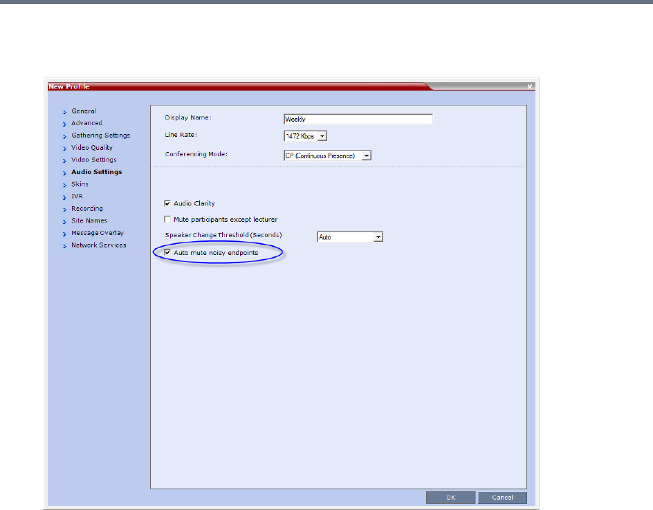
Additional Conferencing Information
Polycom®, Inc. 220
To disable/enable the automatic muting of noisy endpoints in the Conference Profile:
1In a new or existing Conference Profile, click the Audio Settings tab.
In new Profiles, the Auto mute noisy endpoints check box is selected by default.
In existing profiles (after software upgrade from a version prior to 8.1), the Auto mute noisy
endpoints check box is cleared.
2To enable the automatic muting of noisy endpoints, click the Auto mute noisy endpoints check
box.
3Click OK.
Automatic Muting of Noisy Endpoints at the MCU Level
You can disable the automatic muting of noisy endpoints at the MCU level by changing the
ENABLE_SELECTIVE_MIXING flag setting to NO.
In such a case, the automatic muting of noisy endpoints at the conference level (in the Conference Profile
- Audio Settings dialog box) is disabled.
To modify the system flag setting:
●To modify ENABLE_SELECTIVE_MIXING flag setting to NO, manually add it to system.cfg file and
set its value to NO.
For more details, see the Modifying System Flags.

Additional Conferencing Information
Polycom®, Inc. 221
Permanent Conference
A Permanent Conference is any ongoing conference with no pre-determined End Time continuing until it is
terminated by an administrator, operator or chairperson.
Guidelines
●Resources are reserved for a Permanent Conference only when the conference has become
ongoing.
●Resources are allocated to a Permanent Conference according to the Reserve Resources for Video
Participants field. If the number of defined dial-out participants exceeds the value of this field, the
Collaboration Server automatically replaces the number in the Reserve Resources for Video
Participants field with the number of defined dial-out participants in the Permanent Conference.
●Auto Terminate is disabled in Permanent Conferences.
●If participants disconnect from the Permanent Conference, resources that were reserved for its video
and audio participants are released.
●Entry Queues, Conference Reservations and SIP Factories cannot be defined as Permanent
Conferences.
●Additional participants can connect to the conference, or be added by the operator, if sufficient
resources are available.
●The maximum size of the Call Detail Record (CDR) for a Permanent Conference is 1MB.
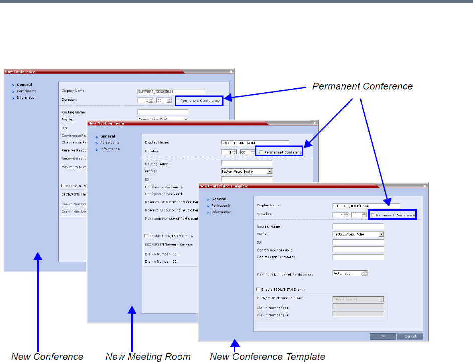
Additional Conferencing Information
Polycom®, Inc. 222
Enabling a Permanent Conference
The Permanent Conference option is selected in the New Conference, New Meeting Room or New
Conference Templates dialog boxes.

Additional Conferencing Information
Polycom®, Inc. 223
Closed Captions
Endpoints can provide real-time text transcriptions or language translations of the video conference by
displaying captions. The captions for a conference may be provided by the captioner who is present in the
conference, or the captioner may use a telephone or web browser to listen to the conference audio. When
the captioner sends a unit of text, all conference participants see it on the main monitor for 15 seconds. The
text then disappears automatically.
The captioner may enter caption text using one of the following methods:
●Remotely, via a dial-up connection to the system’s serial RS-232 port.
●In the room using equipment connected directly to the serial port.
●In the room or remotely, using the Polycom HDX web interface.
Closed Captions Guidelines
●The captions display properties are configured on the endpoint sending the captions.
●Closed Captions content is defined from the endpoint. The Collaboration Server only transmits it to
the endpoints.
●When enabled, captions are available to all endpoints supporting FECC.
●Captions are supported in H.323 and SIP connections.
●The FECC indications during ongoing conferences are used when sending captions.
●When Closed Captions option is enabled for the MCU, muting an endpoint may cause the display of
the Far Mute indication on all the screens of the endpoints connected to the conference.
●The Closed Captions option is not supported in cascading conferences (captions they can only be
viewed in the local conference) as FECC is not supported in cascading links.
●Site name display is not affected by captions display.
●Captions are supported by the Collaboration Server in the following configurations and conferencing
modes:
MPMx Card Configuration Modes.
CP Conferencing Mode.
Encrypted and non-encrypted conferences.
Conferences with content sharing.
•This option is not supported with Collaboration Server 1800.
•This feature is applicable only for AVC endpoints.

Additional Conferencing Information
Polycom®, Inc. 224
Enabling Closed Captions
Captions are enabled by a system flag. By default, Closed Captions are disabled.
To change the flag value:
1On the Collaboration Server menu, click Setup > System Configuration.
The System Flags dialog box opens.
2In the MCMS_PARAMETERS tab, click the New Flag button.
The New Flag dialog box is displayed.
3In the New Flag field enter ENABLE_CLOSED_CAPTION.
4In the Value field enter YES to enable or NO to disable Closed Captions display.
5Click OK to close the New Flag dialog box.
The new flag is added to the flags list.
6Click OK to close the System Flags dialog box.
For flag changes (including deletion) to take effect, reset the MCU. For more information, see
Resetting the Collaboration Server.

Polycom®, Inc. 225
Defining Cascading Conferences
Cascading enables administrators to connect one conference directly to one or several conferences,
depending on the topology, creating one large conference. The conferences can run on the same MCU or
different MCUs.
There are many reasons for cascading conferences, the most common are:
●Connecting two conferences on different MCUs at different sites.
●Utilizing the connection abilities of different MCUs, for example, different communication protocols,
such as, serial connections and ISDN, etc.
Conferences are Cascaded when a link is created between two conferences, usually running on two
different MCUs.
Cascading Link Properties
Cascade links are treated as endpoints in CP conferences. They are allocated resources as any other
endpoint according to Default Minimum Threshold Line Rates and Resource Usage Summary.
They transmit audio, video and content between conferences as well as DTMF codes input from other
endpoints in the conference.
Setting the Video Layout in Cascading conferences require additional consideration.
Setting the Video Layout in Cascading conferences
When cascading two conferences, the video layout displayed in the cascaded conference is determined by
the selected layout in each of the two conferences. Each of the two conferences will inherit the video layout
of the other conference in one of their windows.
In order to avoid cluttering in the cascaded window, it is advised to select appropriate video layouts in each
conference before cascading them.
Note: Cascading support
•Cascading information applies to AVC Conferencing Mode (CP and mixed CP and SVC) only.
•Cascading Conferences are not supported by Collaboration Server (RMX) 1800-0.
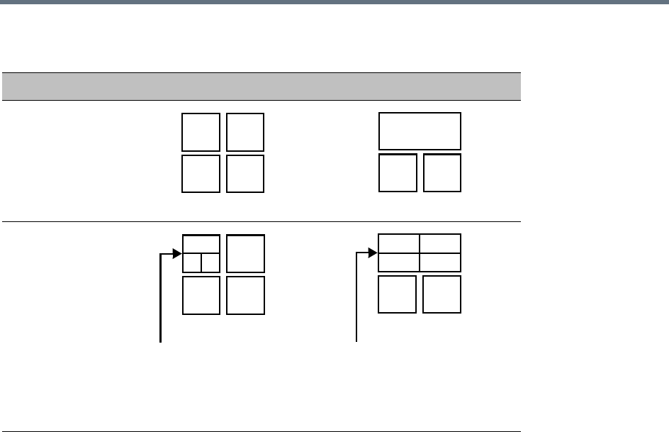
Defining Cascading Conferences
Polycom®, Inc. 226
Guidelines for Setting the Video Layout in Cascading Conferences
To ensure that conferences can be cascaded and video can be viewed in all conferences the following
guidelines are recommended:
●The same version installed on all MCUs participating the cascading topology
●The same license installed on all MCUs participating the cascading topology
●Same Conference Parameters are defined in the Profile of the conferences participating in the
cascading topology
Conference line rates should be identical
Content rate should be identical
Same encryption settings
●DTMF codes should be defined with the same numeric codes in the IVR services assigned to the
cascading conferences
●DTMF forwarding is suppressed
●The video layout of the link is set to 1x1 by the appropriate system flag.
●Cascaded links in 1x1 video layout are in SD resolution.
●When the Mute Participants Except Lecturer option is enabled in the Conference Profile, all
participants (including the link participants) except the lecturer are muted. Only the lecturer is not
muted.
●Gathering is not supported in Cascading Conferences.
Video Layouts in Cascaded Conferences
Conference A Conference B
Without cascading
During cascading
Video layout of conference
B within window of
conference A
Video layout of conference
A within window of
conference B

Defining Cascading Conferences
Polycom®, Inc. 227
Flags Controlling Cascading Layouts
●Setting the FORCE_1X1_LAYOUT_ON_CASCADED_LINK_CONNECTION System Flag to YES
(default) automatically forces the cascading link to Full Screen (1x1) in CP conferences, hence
displaying the speaker of one conference to a full window in the video layout of the other conference.
Set this flag to NO when cascading between an RealPresence Collaboration Server and an MCU that
is functioning as a Gateway, if the participant layouts on the MCU are not to be forced to 1X1.
●Setting the AVOID_VIDEO_LOOP_BACK_IN_CASCADE System Flag to YES (default) prevents the
speaker’s image from being sent back through the participant link from the cascaded conference.
This can occur in cascaded conferences with conference layouts other than 1x1. It results in the
speaker’s own video image being displayed in the speaker’s video layout.
This option is supported with:
In IP (H.323, SIP) and ISDN environments.
Basic Cascading of Continuous Presence and Video Switched conferences. If a Master MCU has
two slave MCUs, participants connected to the slave MCUs will not receive video from each other.
Video resolution will be according to the Resolution Configuration, or VSW profile.
For more details on defining system flags, see Modifying System Flags.
DTMF Forwarding
When two conferences are connected over an IP link, DTMF codes from one conference are not forwarded
to the second conference with the exception of the following operations that are available throughout the
conference and the forwarding of their DTMF codes is not suppressed (i.e. they will apply to both
conferences):
●Terminate conference.
●Mute all but me.
●Unmute all but me.
●Secure conference.
●Unsecure conference.
Play Tone Upon Cascading Link Connection
The RealPresence Collaboration Server can be configured to play a tone when a cascading link between
conferences is established. The tone is played in both conferences.
This tone is not played when the cascading link disconnects from the conferences.
The tone used to notify that the cascading link connection has been established cannot be customized.
The option to play a tone when the cascading link is established is enabled by setting the System Flag
CASCADE_LINK_PLAY_TONE_ON_CONNECTION to YES.
Default value: NO.
The tone volume is controlled by the same flag as the IVR messages and tones:
IVR_MESSAGE_VOLUME.
During cascading between a gateway and a conference all DTMF codes are forwarded from the
gateway to the conference and vice versa.

Defining Cascading Conferences
Polycom®, Inc. 228
Possible Cascading Topologies
The following cascading topologies are available for setting cascading conferences:
●Basic Cascading - only two conferences are connected (usually running on two different
RealPresence Collaboration Servers). The cascaded MCUs reside on the same network.
●Star Cascading - one or several conferences are connected to one master conference. Conferences
are usually running on separate MCUs. The cascaded MCUs reside on the same network.
●MIH (Multi-Hierarchy) Cascading - several conferences are connected to each other in
Master-Slave relationship. The cascaded MCUs can reside on different networks.
System configuration and feature availability change according to the selected cascading topology.
Basic Cascading
In this topology, a link is created between two conferences, usually running on two different MCUs. The
MCUs are usually installed at different locations (states/countries) to save long distance charges by
connecting each participant to their local MCU, while only the link between the two conferences is billed as
long distance call.
●This is the only topology that enables both IP and ISDN cascading links.
●When linking two conferences using an IP cascading link:
The destination MCU can be indicated by:
IP address
H.323 Alias
Both MCUs must be located in the same network.
●The MCU can be used as a gateway.
●The configuration can include two RealPresence Collaboration Servers or one RealPresence
Collaboration Server and one MGC.
●Multiple Cascade Links enabling Cascading between RMXs hosting conferences that include
Immersive Telepresence Rooms (ITP) such as Polycom’s OTX and RPX Room Systems can be
defined. For more information see Creating Multiple Cascade Links Between Telepresence
Conferences.
For properly share content in cascaded conferences, predefined dial in and out link participants must
be defined with Master/Slave settings in the conferences.
When Cascading between the Collaboration Server and third party MCUs, the participant defined in
the Collaboration Server conference must be defined as Master.
When cascading between the Collaboration Server and a Codian MCU, set the system flag
ENABLE_CODIAN_CASCADE to YES to ensure that the Collaboration Server is defined as a Master
in cascading conferences at all times.
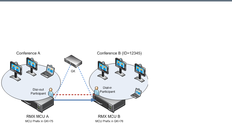
Defining Cascading Conferences
Polycom®, Inc. 229
Basic Cascading Using IP Cascaded Link
In this topology, both MCUs can be registered with the same gatekeeper or the IP addresses of both MCUs
can be used for the cascading link. Content can be sent across the Cascading Link.
Basic Cascading Topology - IP Cascading Link
For example, MCU B is registered with the gatekeeper using 76 as the MCU prefix.
The connection between the two conferences is created when a dial out IP participant is defined (added) to
conference A whose dial out number is the dial-in number of the conference or Entry Queue running on
MCU B.
Dialing Directly to a Conference
Dial out IP participant in conference A dials out to the conference running on MCU B entering the number
in the format:
[MCU B Prefix/IP address][conference B ID].
For example, if MCU B prefix is 76 and the conference ID is 12345, the dial number is 7612345.
Dialing to an Entry Queue
When dialing to an Entry Queue, the dial out participant dials the MCU B prefix or IP address of MCU B and
the Entry Queue ID in the format:
[MCU B Prefix/IP address][EQ B ID]
For example, if MCU B prefix is 76 and the Entry Queue ID is 22558, the dial number is 7622558.
When the participant from conference A connects to the Entry Queue, the system plays to all the participants
in Conference A the IVR message requesting the participant to enter the destination conference ID.
At this point, the Conference A organizer or any other participant in the conference can enter the required
information for the IVR session using DTMF codes. For example, the meeting organizer enters the
destination conference ID - 12345.
Any DTMF input from conference A is forwarded to the Entry Queue on MCU B to complete the IVR session
and enable the move of the participant to the destination conference B.
Once the DTMF codes are entered and forwarded to the Entry Queue on MCU B, the IVR session is
completed, the participant moved to the destination conference and the connection between the two
conferences is established.
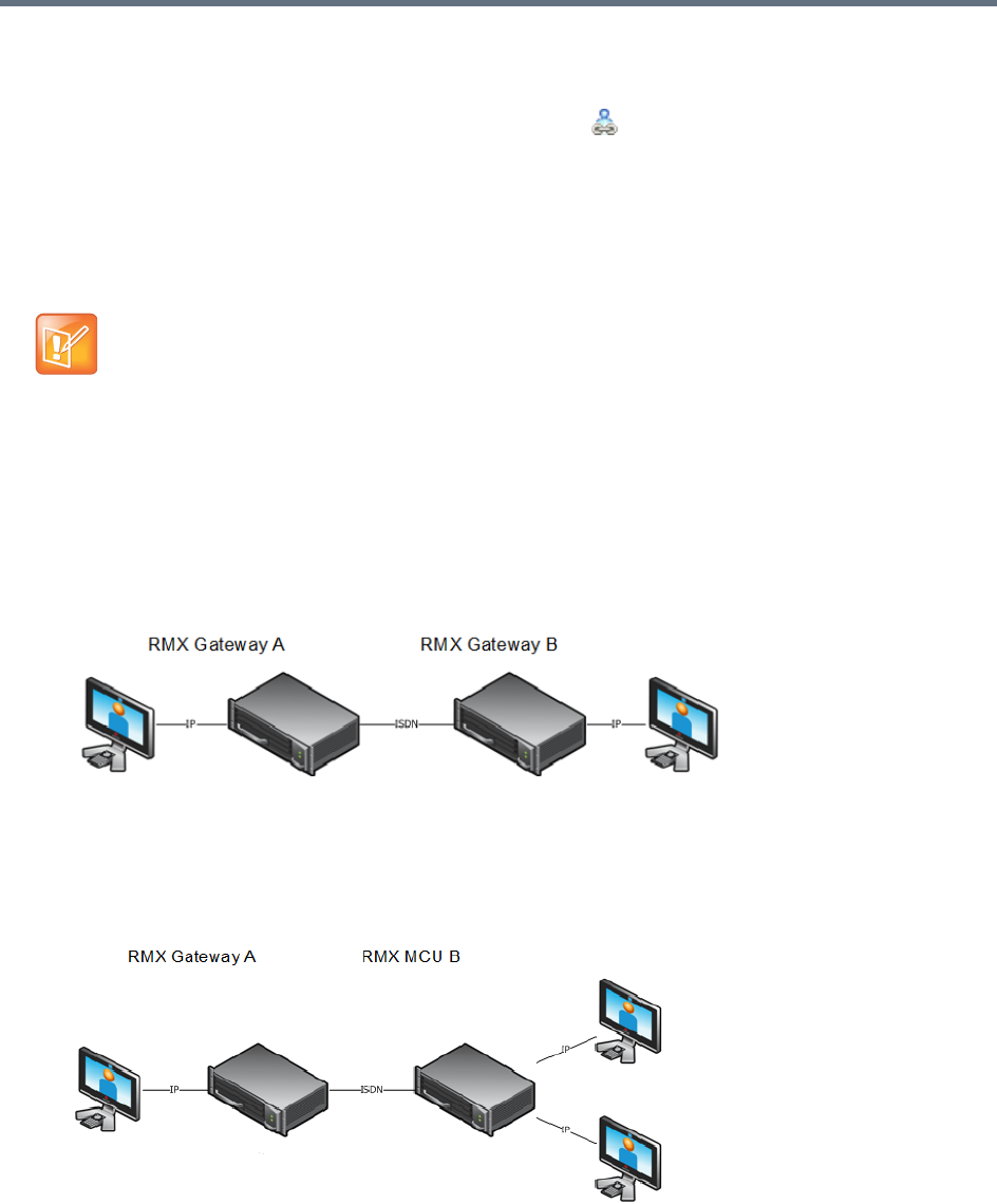
Defining Cascading Conferences
Polycom®, Inc. 230
Automatic Identification of the Cascading Link
In both dialing methods, the system automatically identifies that the dial in participant is an MCU and creates
a Cascading Link and displays the link icon for the participant ( ). The master-slave relationship is
randomly defined by the MCUs during the negotiation process of the connection phase.
Basic Cascading Using ISDN Cascaded Link
ISDN connection can be used to link between two MCUs or MCU and gateway and create a cascading
conference. Content can be sent across the ISDN Cascading Link.
Network Topologies Enabling Content Sharing Over ISDN Cascaded Links
ISDN Cascaded links that support content sharing can be created between two gateways, gateway-to-MCU
or between two MCUs in the following network topologies:
●Gateway to Gateway
Gateway to Gateway Topology
In this topology, an IP participant calls another IP participant over an ISDN link between two
gateways.
●Gateway to MCU
Gateway to MCU/ MCU to Gateway Topology
In this topology, an IP participant calls a conference running on an MCU via a gateway and over an
ISDN link.
ISDN Cascaded Links are not supported when the RealPresence Collaboration Server is in Ultra
Secure Mode. For more information see Ultra Secure Mode.
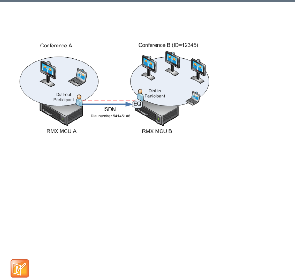
Defining Cascading Conferences
Polycom®, Inc. 231
●MCU to MCU
Cascading Between Two MCUs Using an ISDN Link
In this topology, an ISDN participant from conference running on MCU A calls a conference running
on MCU B over an ISDN link.
Guidelines
●Content is restricted. When another endpoint wants to send content, the first endpoint must stop
sending content before the second endpoint can initiate or send content.
●Endpoints that do not support H.239 can receive the Content using the Send Content to Legacy
Endpoints option.
●When a participant joins a conference with active Content, content cannot be viewed by the new
participant. Restart the Content.
●Cascaded MCUs/Gateways must be registered with the same Gatekeeper or neighboring
Gatekeepers. MCUs and endpoints must also be registered with Gatekeepers.
●Gateway/MCU calls require definition of IVR Services. For more information see Defining the IVR
Service for Gateway Calls.
Gateway to Gateway Calls via ISDN Cascading Link
When H.323 participants connects to another IP participants via a Gateway to Gateway call over an ISDN
link, the dialing string includes the following components:
[GW A prefix in GK] - The prefix with which the RealPresence Collaboration Server (gateway) is
registered to the gatekeeper.
[GW Profile ID] - The ID of the Gateway Profile defined on Gateway A to be used for routing the call to
the Gateway B.
[GW Profile ISDN/PSTN number] - The dial-in number assigned to the Gateway Profile defined on
Gateway B, including the required country and area codes.
The content sharing protocol is H.263 when sent over ISDN Cascading link.

Defining Cascading Conferences
Polycom®, Inc. 232
Information required that is not part of the dialing string:
[Destination number] - The destination number as alias, IPv4 address or ISDN/PSTN number of
participant B.
The dialing string format:
H.323 Participants connecting to another IP participant via a Gateway to Gateway call over an ISDN link
enter a dial string using the format:
<GW A Prefix in GK><Gateway Profile_ID on GW A>*<Destination ISDN Dial-in number
assigned to the Gateway Session Profile GW B>*<Destination Number, participant>
For example:
H.323 participant dials: 229999*4444103, and when prompted for the Destination number enters 3456
followed by the pound key (#) using DTMF codes
SIP Participants connecting to another IP participant via a Gateway to Gateway call over an ISDN link enter
a dial string using the format:
<Gateway Profile_ID on GW A>@<Central Signaling IP GW A>*<Destination ISDN
Dial-in number assigned to the Gateway Session Profile GW B>*<Destination
Number, participant>
For example:
If Central Signaling IP address of Gateway A is 172.22.177.89, SIP participant dials: 9999@
172.22.177.89* 4444103 and when prompted for the Destination number enters 3456 followed by the
pound key (#) using DTMF codes.
Gateway to MCU Calls via ISDN Cascading Link
When H.323 participants connects to a conference/Meeting Room via a Gateway to MCU call over an ISDN
link, the dialing string includes the following components:
[GW A prefix in GK] - The prefix with which Gateway A is registered to the gatekeeper.
[GW Profile ID on GW A] - The ID of the Gateway Profile on GW A to be used for routing the call to
the Meeting Room/conference running on MCU B.
[Conference/Meeting Room/Entry Queue ISDN/PSTN number] - The dial-in number assigned to
the Entry Queue/Meeting Room/Conference defined on MCU B, including the required country and area
codes.
Information required that is not part of the dialing string:
[Destination Conference ID] - Only if using the Entry Queue on MCU B for routing calls or creating
new ad hoc conferences. The ID of the destination conference on MCU B.
GW A prefix in Gatekeeper - (not used with SIP) 22
Gateway Profile ID in GW A 9999
ISDN Dial-in Number assigned to the Gateway Session
Profile GW B
4444103
IP Participant Alias 3456

Defining Cascading Conferences
Polycom®, Inc. 233
The dialing string format:
<GW A Prefix in GK><Gateway Profile_ID on GW A>*<ISDN Number assigned to the
Meeting Room/Conference/Entry Queue>
For Example:
SIP participant dials (if Central Signaling IP address of Gateway A is 172.22.177.89) 9999@
172.22.177.89 IP* 4444100
If dialing an Entry Queue, when prompted for the Destination number enters 3456 followed by the pound
key (#) using DTMF codes to create a new conference or join an ongoing conference with that ID.
MCU to MCU Calls via ISDN Cascading Link
A dial out ISDN participant is defined (added) to conference A running on MCU A. The participant’s dial out
number is the dial-in number of the Entry Queue or conference running on MCU B (for example 54145106).
MCU A dials out to an Entry Queue or conference B running on MCU B using the Entry Queue number (for
example 54145106) or the conference number.
When the participant, who is a dial-in participant in conference B, connects to the Entry Queue, the system
plays to all the participants in Conference A the IVR message requesting the participant to enter the
destination conference ID (or if connecting to a conference directly, the participant is requested to enter the
conference password).
At this point the Conference A organizer or any other participant in the conference can enter the required
information for the IVR session using DTMF codes. For example, the meeting organizer enters the
destination conference ID - 12345.
Any DTMF input from conference A is forwarded to the Entry Queue on MCU B to complete the IVR session
and enable the move of the participant to the destination conference B.
Once the DTMF codes are entered and the IVR session is completed, the participant is connected to the
conference and the connection between the conferences is established. The system automatically identifies
the calling participant as an MCU and the connection is identified as a cascading link and the cascading link
icon is displayed for the participant ( ).
RealPresence Collaboration Server Configuration Enabling ISDN Cascading Links
To enable Gateway-to-Gateway, Gateway-to-MCU and MCU-to-MCU calls over ISDN Cascading links, the
following configurations are required:
●Modifying the IP Network Service to include the MCU Prefix in the Gatekeeper (in the Gatekeepers
dialog box). For more details, see Modifying the Default IP Network Service.
●ISDN Network Service is configured in both MCUs. For more details, Modifying an ISDN/PSTN
Network Service.
●Configuring a Gateway Profile and assigning dial-in ISDN/PSTN numbers. For details, see Defining
the Gateway Profile.
GW A prefix in Gatekeeper - (not used with SIP) 22
Gateway Profile ID in GW A 9999
ISDN Dial-in Number assigned to the Entry Queue/MR/conference 4444100
H.323 participant dials 229999*4444100
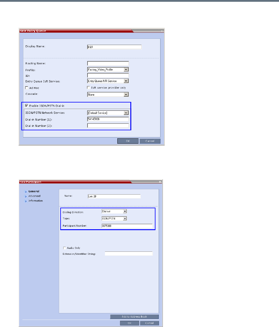
Defining Cascading Conferences
Polycom®, Inc. 234
●Configure the Entry Queue or conference (for direct dial-in) as enabled for ISDN connection and a
dial-in number is assigned (for example 54145106).
●Defining the dial-in ISDN participant in MCU B and Dial-out ISDN participant in MCU A (for
MCU-to-MCU cascading conferences).
A dial out ISDN participant is defined (added) to conference A. The participant’s dial out number is
the dial-in number of the Entry Queue or conference running on MCU B (for example 54145106).
MCU A dials out to an Entry Queue or conference B running on MCU B using the Entry Queue
number (for example 54145106) or the conference number.

Defining Cascading Conferences
Polycom®, Inc. 235
Conference Profile Definition
The following table lists the recommended Meeting Room/Conference Profile parameters setting when
routing ISDN cascaded calls.
Recommended Conference Profile Options Setting
Line Rate Motion Sharpness Encryption LPR
128
128
128
128
256
256
256
256
384
384
384
384
512
512
512
512
768
768
768
768

Defining Cascading Conferences
Polycom®, Inc. 236
MCU Interoperability Table
The following table lists the different MCU and Gateway configurations that are supported or implemented
when routing Cascaded ISDN calls.
Since the remote participant settings are unknown, it is recommended that the gateway or endpoint
be configured to support a higher line rate (for example, 768 Kbps) to allow flexibility during endpoint
capability negotiations.
MCU Interoperability Table
Source Destination Scenario Version(s)
RealPresence
Collaboration
Server Gateway
RealPresence
Collaboration
Server MCU
User calls via a Gateway to a Remote
Conference (user to conference)
RealPresence Collaboration
Server v. 7.1 or later
RealPresence
Collaboration
Server Gateway
RealPresence
Collaboration
Server Gateway
User calls via a Gateway to a Remote
User behind Gateway (user to user)
RealPresence Collaboration
Server v. 7.1 or later
RealPresence
Collaboration
Server MCU
RealPresence
Collaboration
Server MCU
A dial out participants calls to a remote
conference (conference to conference)
RealPresence Collaboration
Server v. 7.1 or later
RealPresence
Collaboration
Server MCU
RealPresence
Collaboration
Server Gateway
A dial out participants calls to a remote
User behind a Gateway (Conference to
User)
RealPresence Collaboration
Server v. 7.1 or later
Endpoint RealPresence
Collaboration
Server Gateway
User calls directly to a remote user behind
a Gateway (User to User)
RealPresence Collaboration
Server v. 7.1
RealPresence
Collaboration
Server MCU
Codian
Gateway
Dial out participants use a fixed rule
behind the Codian Gateway.
RealPresence Collaboration
Server v. 7.1
Latest Codian version
RealPresence
Collaboration
Server Gateway
Codian
Gateway
Dial out participants use a fixed rule
behind the Codian Gateway.
RealPresence Collaboration
Server v. 7.1
Latest Codian version
Codian Gateway RealPresence
Collaboration
Server MCU
User calls via a Codian Gateway to a
Remote Conference (user to conference)
RealPresence Collaboration
Server v. 7.1
Latest Codian version
Codian Gateway RealPresence
Collaboration
Server Gateway
User calls via a Codian Gateway to a
Remote User behind RealPresence
Collaboration Server Gateway (user to
user)
RealPresence Collaboration
Server v. 7.1
Latest Codian version
RealPresence
Collaboration
Server MCU
Radvision
Gateway
User calls via a Radvision Gateway to a
Remote User behind RealPresence
Collaboration Server Gateway (user to
user)
RealPresence Collaboration
Server v. 7.1
Latest Radvision version
Defining Cascading Conferences
Polycom®, Inc. 237
RealPresence
Collaboration
Server Gateway
Radvision
Gateway
User calls via a Radvision Gateway to a
Remote User behind RealPresence
Collaboration Server Gateway (user to
user)
RealPresence Collaboration
Server v. 7.1
Latest Radvision version
Radvision
Gateway
RealPresence
Collaboration
Server MCU
User calls via a Radvision Gateway to a
Remote Conference (user to conference)
RealPresence Collaboration
Server v. 7.1
Latest Radvision version
Radvision
Gateway
RealPresence
Collaboration
Server Gateway
User calls via a Radvision Gateway to a
Remote User behind RealPresence
Collaboration Server Gateway (user to
user)
RealPresence Collaboration
Server v. 7.1
Latest Radvision version
Endpoint RealPresence
Collaboration
Server Gateway
User calls directly to a DMA controlled
environment
RealPresence Collaboration
Server v. 7.1
RealPresence
Collaboration
Server MCU
RealPresence
Collaboration
Server Gateway
A dial out participants calls to a remote
conference on a DMA controlled
environment
RealPresence Collaboration
Server v. 7.1
MCU Interoperability Table
Source Destination Scenario Version(s)
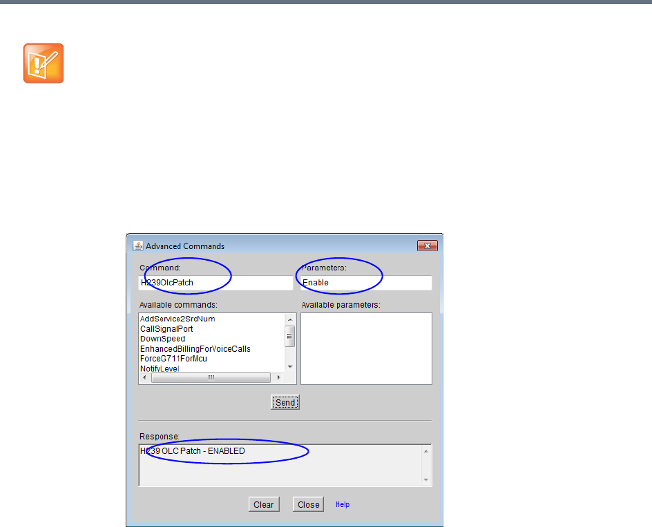
Defining Cascading Conferences
Polycom®, Inc. 238
Suppression of DTMF Forwarding
Forwarding of the DTMF codes from one conference to another over an ISDN cascading link is not
automatically suppressed as with IP cascading link and it can be limited to basic operations while
suppressing all other operations by a system flag DTMF_FORWARD_ANY_DIGIT_TIMER_SECONDS.
System Flag Settings
The DTMF_FORWARD_ANY_DIGIT_TIMER_SECONDS flag determines the time period (in seconds) that
MCU A will forward DTMF inputs from conference A participants to MCU B.
Once the timer expires, most of the DTMF codes (excluding five operations as for IP links) entered in
conference A will not be forwarded to conference B. This is done to prevent an operation requested by a
participant individually (for example, mute my line) to be applied to all the participants in conference B.
Flag range (in seconds): 0 - 360000
This flag is defined on MCU A (the calling MCU).
•On the Codian gateway Content is not supported with line rates of 128Kbps and below.
•When using the following topology:
H.323 endpoint > Codian Gateway > ISDN Link - RealPresence Collaboration Server > H.323
endpoint, the Codian Gateway is unable to send DTMF and the call is disconnected (VNGFE-
3587).
•To send Content from a participant over Radvision Gateway to a conference/participant, the
GWP20 patch must be installed in the RadVision gateway:
On the Radvision gateway, open the GWP20 User Interface.
Select Settings > Advanced Commands.
In the Command box, enter H239OlcPatch.
In the Parameters box, enter Enable and then click Send.

Defining Cascading Conferences
Polycom®, Inc. 239
If a flag is not listed in the System Flags list it must be added to the system.cfg file before it can be modified.
For more details on defining system flags, see Modifying System Flags.
Star Cascading Topology
In the Star topology (as well as in the Basic topology), the MCUs are usually installed at different locations
(states/countries) and participants connect to their local MCU to facilitate the connection and save long
distance call costs. Star Topology Cascading requires that all cascaded MCUs reside on the same network.
Content sharing is available to all conferences over the H.323 Cascading Link.
In this topology, the MCUs are networked together using two modes:
●Master-Slave Cascading
●Cascading via Entry Queue
Master-Slave Cascading
It is similar to MIH (Multi Hierarchy) cascading, with only two levels: one Master MCU on level 1 and several
Slave MCUs on level 2.
The cascading hierarchy topology can extend to four levels (MIH Cascade - a Sample 3-Level Cascading
Configuration) and should be deployed according to the following guidelines:
●If an RealPresence Collaboration Server is deployed on level 1:
RealPresence Collaboration Server systems can be used on level 2
MGC with version 9.0.4 can be used on level 2 if RealPresence Collaboration Server version 7.0.2
and higher is deployed in level 1
●If an MGC is deployed on level 1:
MGC or RealPresence Collaboration Server can be used on level 2.
Although participants in Star Cascading conferences can connect to their local conference using IP
(H.323, SIP) and ISDN, the Cascading Links between conferences must connect via H.323.
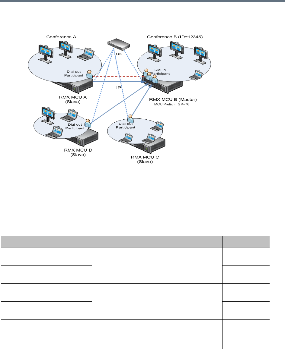
Defining Cascading Conferences
Polycom®, Inc. 240
Master-Slave Star Cascading Topology
●When creating a cascading link between two RealPresence Collaboration Servers:
The RealPresence Collaboration Servers operate in CP (Continuous Presence) mode.
●When creating a cascading link between MGCs and RealPresence Collaboration Servers:
The MGCs can only operate in VSW mode.
The following table summarizes Video Session Modes line rate options that need to be selected for each
conference in the cascading hierarchy according to the cascading topology:
MIH Cascading – Video Session Mode and Line Rate
Topology MCU Type Video Session Mode Line Rate Endpoint
Level 1 RealPresence
Collaboration Server
CP - HD 1.5Mb/s, 1Mb/s, 2Mb/s HDX
Level 2 RealPresence
Collaboration Server
Level 1 RealPresence
Collaboration Server
CP - CIF 768Kb/s, 2Mb/s VSX
Level 2 RealPresence
Collaboration Server
Level 1 MGC CP - CIF 263 768Kb/s, 2Mb/s HDX, VSX
Level 2 RealPresence
Collaboration Server
CP - CIF 264
Defining Cascading Conferences
Polycom®, Inc. 241
To establish the links between two RealPresence Collaboration Servers requires the following procedures
be performed:
●Establish the Master-Slave relationships between the cascaded conferences by defining the dialing
direction.
●Create the Master and Slave conferences, defining the appropriate line rate.
●Create a cascade-enabled Dial-out Participant link in the Master conference
●Create a cascade-enabled Dial-in Participant link in the Slave conference.
Creating a Cascade Enabled Dial-out/Dial-in Participant Link
The connection between two cascaded conferences is established by a cascade enabled dial-out and dial-in
participants, acting as a cascades link.
The dialing direction determines whether the dial-out participant is defined in the conference running on the
Master MCU or the Slave MCU. For example, if the dialing direction is from the Master conference on level
1 to the Slave conference on level 2, the dial-out participant is defined in the Master conference on level 1
and a dial-in participant is defined in the Slave conference running on the MCU on level 2.
If the cascade-enabled dial-out participant always connects to the same destination conference on the other
(second) MCU, the participant properties can be saved in the Address Book of the MCU for future repeated
use of the cascaded link.
To define the dial-out cascade participant link:
1In the Conferences pane, select the conference.
Level 1 MGC VSW - HD 1.5Mb/s HDX
Level 2 RealPresence
Collaboration Server
VSW - HD
MIH Cascading – Video Session Mode and Line Rate
Topology MCU Type Video Session Mode Line Rate Endpoint
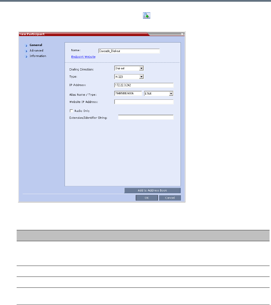
Defining Cascading Conferences
Polycom®, Inc. 242
2In the Participants pane, click New Participant ().
The New Participant - General dialog box is displayed.
3Define the following parameters:
New Participant – Dial-out Cascade Link
Field Description
Name Enter the participant’s name.
This field may not be left blank. Duplicate participant names, comma, and
semi-colon characters may not be used in this field.
Dialing Direction Select Dial-out.
Type Select H.323.
IP Address Enter the IP address of the Signaling Host of the MCU running the other (second)
conference, where the cascade enabled Entry Queue is defined.
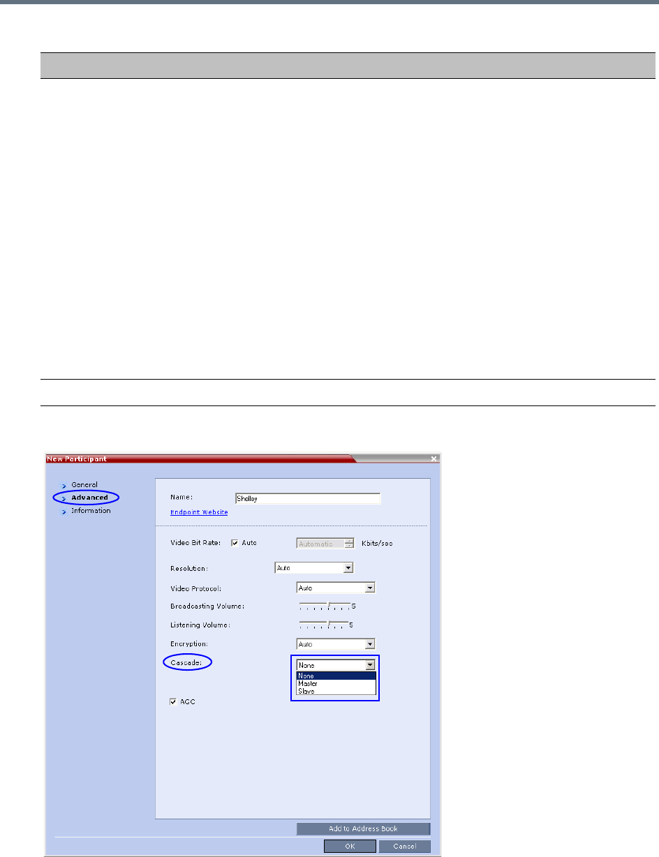
Defining Cascading Conferences
Polycom®, Inc. 243
4Click the Advanced tab.
Alias Name If you are using the target MCU IP address, enter the Conference ID of the target
conference. For example: 24006
If a gatekeeper is used, instead of the IP address, you can enter the prefix of the
target MCU as registered with the gatekeeper, as part of the dialing string and the
conference ID in the format:
<Target MCU Prefix><Conference_ID>
For example: 92524006
If the conference has a password and you want to include the password in the dial
string, append the password to in the dial string after the Conference ID.
For example: 92524006##1234
If the conference has a password and you do not want to include the password in
the dial string, set the
ENABLE_CASCADED_LINK_TO_JOIN_WITHOUT_PASSWORD flag to YES.
For more information see Modifying System Flags.
Alias Type Select E.164 (digits 0-9, *, #).
New Participant – Dial-out Cascade Link
Field Description
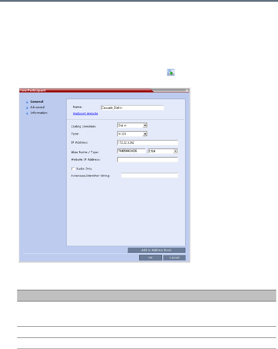
Defining Cascading Conferences
Polycom®, Inc. 244
5In the Cascade field, select:
Slave (if the participant is defined in a conference running on a Slave MCU).
Master
(if the participant is defined in a conference running on the Master MCU)
.
6Click OK.
To define a Dial-in Participant as the cascade link:
1In the Participants list, click the New Participant button( ).
The New Participant - General dialog box opens.
2Define the following parameters:
New Participant – Dial-in Cascade Link
Field Description
Display Name Enter the participant’s name.
This field may not be left blank. Duplicate participant names, comma, and
semi-colon characters may not be used in this field.
Dialing Direction Select Dial-in.
Type Select H.323.
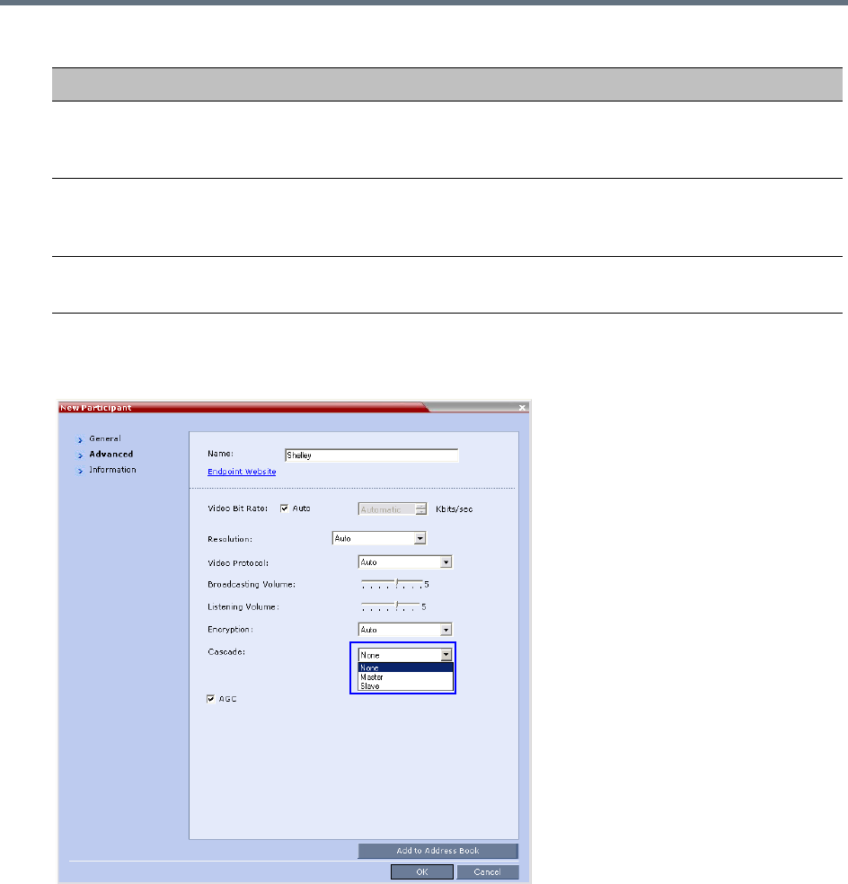
Defining Cascading Conferences
Polycom®, Inc. 245
3Click the Advanced tab.
The Advanced dialog box opens.
4In the Cascaded Link field, select:
Slave, if the participant is defined in a conference running on a Slave MCU.
Master, if the participant is defined in a conference running on the Master MCU.
5Click the OK button.
IP Address If a gatekeeper is used: This field is left empty.
If a gatekeeper is not used: Enter the IP address of the Signaling Host of the
MCU running the other conference.
Alias Name If a gatekeeper is used: Enter the name of the other (second) conference.
If a gatekeeper is not used: Enter the ID of the MCU running the other (second)
conference.
Alias Type If a gatekeeper is used: H.323 ID
If a gatekeeper is not used: Select E.164 (digits 0-9, *, #).
New Participant – Dial-in Cascade Link (Continued)
Field Description

Defining Cascading Conferences
Polycom®, Inc. 246
Cascading via Entry Queue
The link between the two conferences is created when a participant that is defined as a dial-out cascaded
link in one conference (Conference A) connects to the second conference (Conference B) via a special
cascaded Entry Queue (EQ). When MCU A dials out to the cascaded link to connect it to conference A, it
actually dials out to the cascaded Entry Queue defined on MCU B.
Cascaded Conferences - Star Topology
Though the process of cascading conferences mentioned in this section refers to conferences running on
two different RealPresence Collaboration Server units, it is possible to cascade conferences running
between RealPresence Collaboration Server units and other MCUs.
The following features are not supported by the cascaded link and therefore are not supported in the
combined conference:
●DTMF codes are enabled in cascaded conference, but only in their local conference. The operations
executed via DTMF codes are not forwarded between linked conferences.
●FECC (Far End Camera Control will only apply to conferences running in their local MCU).
Enabling Cascading
Cascading two conferences requires that the following procedures are implemented:
●Creating the cascade-enabled Entry Queue
A cascade-enabled Entry Queue must be created in the MCU hosting the destination conference
(Conference B). The cascade-enabled Entry Queue is used to establish the dial-in link between the
destination conference and the linked conference and bypassing standard Entry Queue, IVR prompt
and video slide display.
●Creating a cascade-enabled Dial-out link
The creation of a cascade-enabled dial-out link (participant) in the linked conference (Conference A).
This dial-out participant functions as the link between the two conferences.
●(Optional) Enabling the cascaded linked participant to connect to the linked conference (Conference
A) without entering the conference password. This can be done by modifying the default settings of
the relevant system flag.
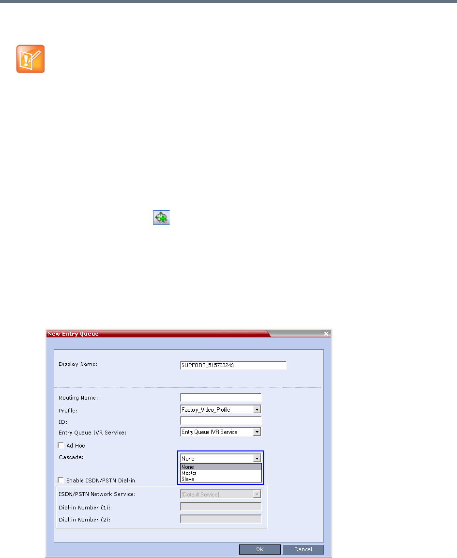
Defining Cascading Conferences
Polycom®, Inc. 247
Creating the Cascade-enabled Entry Queue
The cascade-enabled Entry Queue maintains the correct behavior of the cascaded link when it dials into it.
When cascading High Definition (HD) conferences, the cascade-enabled Entry Queue must have the same
settings as both cascaded conferences and the participants in both conferences must use the same line rate
and HD capabilities as set for the conferences and Entry Queue.
To Define a Cascade-Enabled Entry Queue:
1In the RealPresence Collaboration Server Management pane, click the Entry Queues button.
The Entry Queues list pane is displayed.
2Click the New Entry Queue button.
The New Entry Queue dialog box is displayed.
3Define the standard Entry Queue parameters (as described in Defining a New Entry Queue).
4In the Cascade field, select Master or Slave depending on the Master/Slave relationship.
Set this field to Master if the Entry Queue is defined on the MCU that is at the center of the
topology and other conferences dial into it (acting as the Master).
Set this field to Slave if the Entry Queue is defined on the MCU acting as a Slave, that is, to which
the link from the Master MCU (MCU at the center of the topology) is dialing.
If you are defining an HD cascaded Entry Queue, it is recommended to select the same Profile that
is selected for both conferences.
The cascade-enabled Entry Queue should be used only to connect cascaded links and should not be
used to connect standard participants to conferences.
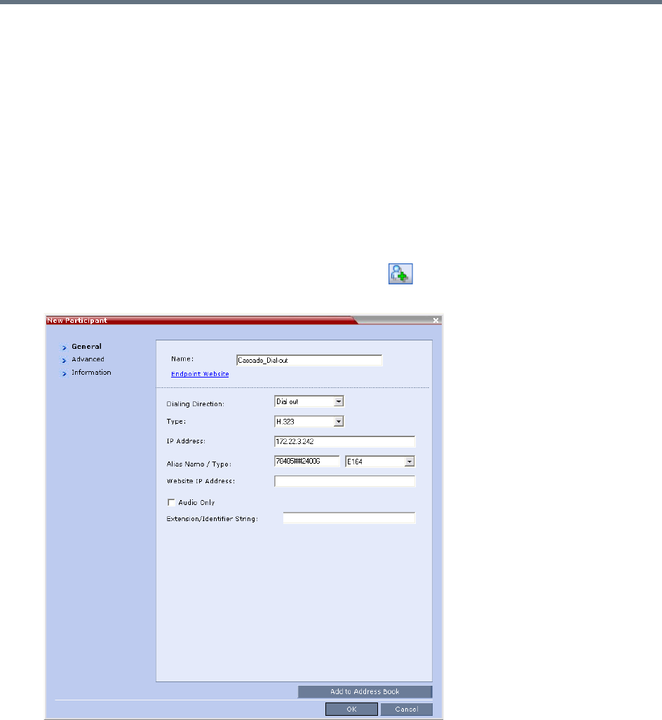
Defining Cascading Conferences
Polycom®, Inc. 248
5Click OK.
The new Entry Queue enabling cascading is created.
Creating the Dial-out Cascaded Link
The dial-out link (participant) is created or added in the linked conference (Conference A). The dial-out string
defined for the participant is the dialing string required to connect to the destination conference (Conference
B) Entry Queue defined on the MCU hosting the destination cascaded conference. The dial-out participant
can be defined in the Address Book and added to the conference whenever using the same
cascade-enabled Entry Queue and a destination conference (with the same ID and Password).
To define the Dial-out Cascaded Link:
1Display the list of participants in the linked conference (Conference A).
2In the Participant List pane, click the New Participant button.
The New Participant - General dialog box is displayed.
3In the Name field, enter a participant name.
4In the Dialing Direction field, select Dial-out.
5In the Type list field, verify that H.323 is selected.
6There are two methods to define the dialing string:
aUsing the MCU’s IP Address and the Alias string - see Method A.

Defining Cascading Conferences
Polycom®, Inc. 249
bUsing only the Alias string (requires a gatekeeper) - see Method B.
Method A
In this method no gatekeeper is used.
In the IP Address field, enter the IP address of the Signaling Host of the MCU hosting the
destination conference (in the example, MCU B).
In the Alias Name/Type field, enter the ID of the cascade-enabled Entry Queue (EQ), the Conference
ID and Password of the destination conference (MCU B) as follows:
<EQ ID>#<Destination Conference ID>#<Password> (Password is optional).
Method B
In this method a gatekeeper is used:
In the Alias Name field, enter the Prefix of MCU B, EQ ID, Destination Conference ID, and Password,
as follows:
<MCU Prefix EQ ID>#<Conference ID>#<Password> (Password is optional)
7Click the Advanced tab.
8In the Cascade field, select:
Slave, if the participant is defined in a conference running on a Slave MCU and will connect to the
Master MCU (in the center of the topology).
Master
, if the participant is defined in a conference running on the Master MCU
(in the center of
the topology)
dialing from the Master MCU to the Slave MCU
.
For Example: 78485#24006#1234
Cascade-enabled
EQ ID
Destination
Confer
Password (optional)
For Example: 92578485#24006#1234
Cascade-enabled
EQ ID
Conference ID
Password (optional)MCU Prefix as
registered in
the
gatekeeper
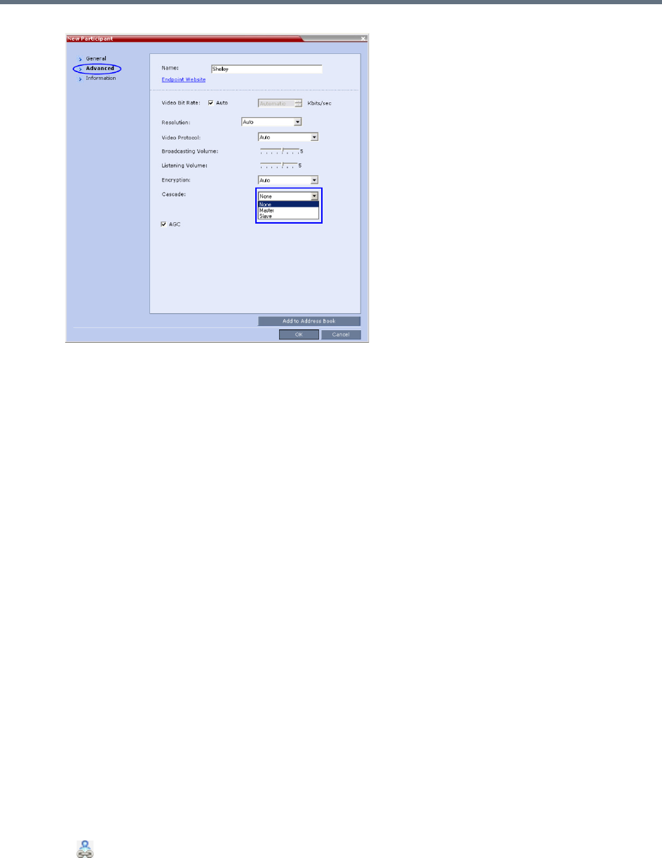
Defining Cascading Conferences
Polycom®, Inc. 250
9Click OK.
The cascade-enabled dial-out link is created and the system automatically dials out to connect the
participant to the linked conference, as well as the destination conference.
Enabling Cascaded Conferences without Password
If a password is assigned to the linked conference, cascaded links will be prompted for a password when
connecting to it (Conference A). Administrators have the option of altering the MCU settings to enable
cascaded links to connect without a password.
To enable cascaded links to connect without a password:
1In the RealPresence Collaboration Server web client connected to MCU A (where the linked
conference is running), click Setup >System Configuration.
The System Flags dialog box opens.
2Set the ENABLE_CASCADED_LINK_TO_JOIN_WITHOUT_PASSWORD flag to YES.
3Click OK.
For more information, see Modifying System Flags.
Reset the MCU for flag changes to take effect.
Monitoring Star Cascaded Conferences
To monitor both conferences at the same time, two instances of the RealPresence Collaboration Server
Web Clients must be opened (one for each MCU) by entering the IP Address of each MCU. If both
conferences are running on the same MCU, only one RealPresence Collaboration Server Web Client
window is required.
When conferences are cascaded, the Participant List pane of each of the two conferences will display a
linked icon ( ); a dial-in linked icon in the destination conference (Conference B) and a dial-out linked icon
in the linked conference (Conference A).
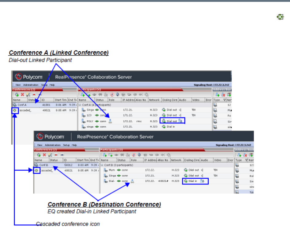
Defining Cascading Conferences
Polycom®, Inc. 251
The Conferences List panes in each of the two conferences will display a cascaded conference icon ( )
indicating that a conference running on the MCU is presently cascading with another conference running
on the same or another MCU. The cascaded conference icon will be displayed for a short period of time and
then disappear.
Creating the Dial-out Link from a Conference Running on the MGC to
the Conference Running on the RealPresence Collaboration Server
In the same way that the dial-out cascaded link is created in the RealPresence Collaboration Server, you
can create a dial-out participant in the MGC.
In the MGC Manager application, define a new participant as follows:
1In the Participant Properties dialog box, enter a Participant Name, select Dial-out and H.323.
2Define the dialing string as described in step 6 in the procedure for defining the dial-out cascaded
link.
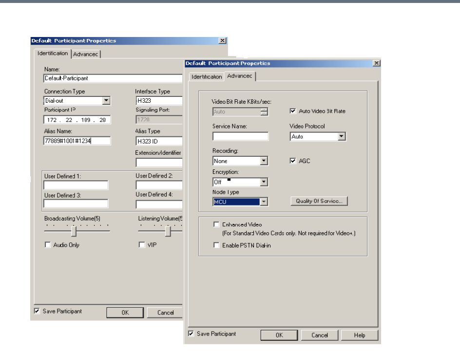
Defining Cascading Conferences
Polycom®, Inc. 252
3In the Advanced tab, in the Node Type field, select MCU.
4Click OK.
Cascading Conferences - H.239-enabled MIH Topology
H.239 Multi-Hierarchy (MIH) cascading is available to RealPresence Collaboration Server users enabling
them to run very large conferences on different MCUs in multiple levels of Master-Slave relationships using
an H.323 connection.
Multi-Hierarchy (MIH) Cascading is implemented where the cascaded MCUs reside on different networks,
whereas Star Topology Cascading requires that all cascaded MCUs reside on the same network.
MIH Cascading allows:
●Opening and using a content channel (H.239) during conferences.
●Full management of extremely large, distributed conferences.
●Connecting conferences on different MCUs at different sites.
●Utilizing the connection abilities of different MCUs, for example, different communication protocols,
such as, serial connections, ISDN, etc.
●Significant call cost savings to be realized by having participants call local MCUs which in turn call
remote MCUs, long distance.
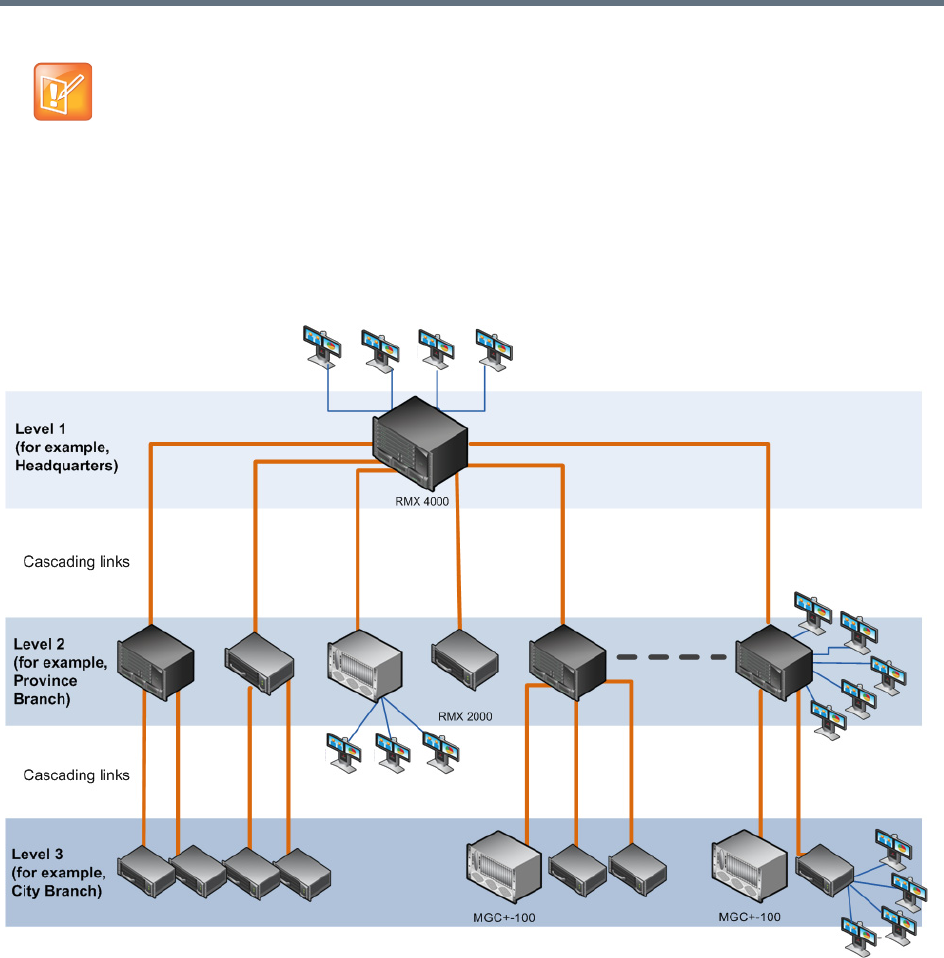
Defining Cascading Conferences
Polycom®, Inc. 253
.
MIH Cascading Levels
The cascading hierarchy topology can extend to up to four levels (as shown below), where the most
common configuration includes up to three levels.
MIH Cascade - a Sample 3-Level Cascading Configuration
Cascading Topologies
The cascading hierarchy topology should be deployed according to the following guidelines:
●If an RMX is deployed on level 1 (recommended deployment):
Any RMX can be used on level 2, 3 and 4 (recommended deployment),
MGC version 9.0.4 can be used on level 2 and level 3,
DST MCS 4000 and other MCUs can be deployed on levels 3 and 4.
●If an MGC is deployed on level 1:
MGC or RMX can be used on level 2.
Although participants in MIH Cascading conferences can connect using IP (H.323, SIP) and ISDN, the
MIH Cascading Links must connect via H.323.
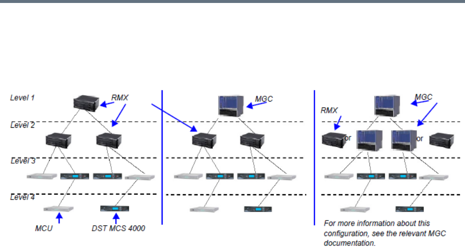
Defining Cascading Conferences
Polycom®, Inc. 254
DST MCS 4000 and other MCUs can be deployed on levels 3 and 4.
●DST MCS 4000 MCUs connect as endpoints to the RMXs or MGCs on higher levels.
MIH Cascade Levels
MIH Cascading Guidelines in CP Licensing
Master - Slave Conferences
●It is recommended to have RMX systems at all levels to leverage the high quality video and content
offered by the RMX.
●In MIH Cascading conferences, although there are multiple levels of Master and Slave relationships
between conferences, the conference that runs on the MCU on level 1 of the hierarchy must be the
Master for the entire cascading session. When an MGC is part of the cascading topology, it can be
configured at any level if MGC Version 9.0.4 is installed, otherwise, it must be set as Level 1 MCU.
●Conferences running on MCUs on levels 2 and 3 and can be both Masters and Slaves to conferences
running on MCUs on levels above and below them.
●All conferences running on MCUs on the lowest level in the configuration (for example, level 3 in a
3-level hierarchy configuration) are Slave conferences.
●When the DST MCS 4000 is on level 3 and acting as slave to level 2, the RMX on level 2 must dial
out to it in order for the DST MCS 4000 to be identified as slave. The link between the two MCU (dial
out participant) is defined as a standard participant and not as a cascading link.
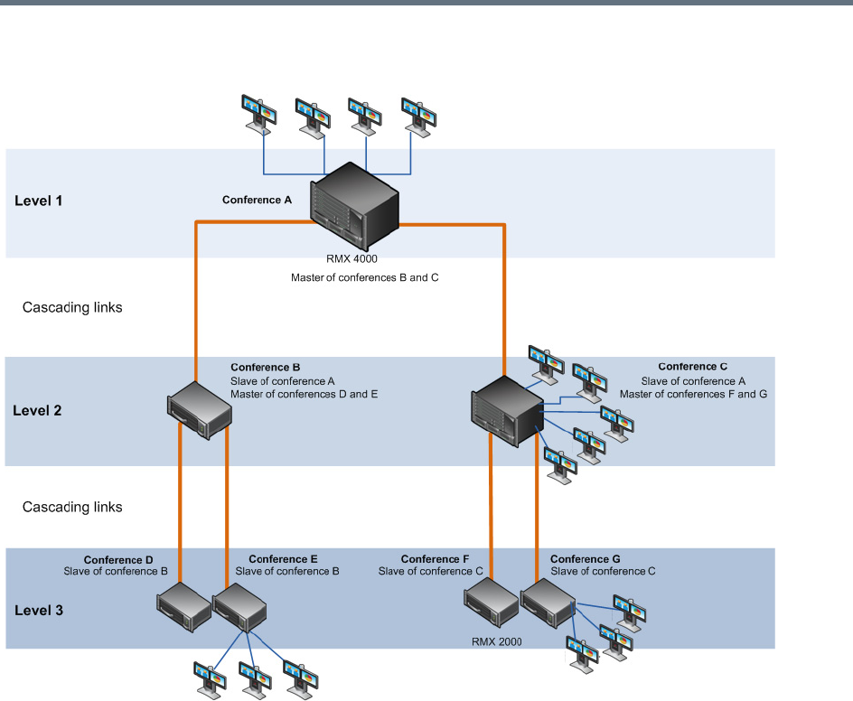
Defining Cascading Conferences
Polycom®, Inc. 255
MIH Cascading – Master-Slave Relationship
Video Session Mode, Line Rate and Video Settings
The types of MCUs, their position in the cascade topology and the endpoint capabilities (HD/CIF and
H.263/H.264) determine the Video Session Type of the MIH Cascading conference.
●When creating a cascading link between two RMXs:
The RMXs operate in CP (Continuous Presence) mode.
DTMF codes should be defined with the same numeric codes in the IVR services assigned to the
cascading conferences.
●When creating a cascading link between MGCs and RMXs:
If there are no MGCs on level 2, the MGCs can operate in either in CP or VSW (Video Switching)
mode.
If there are MGCs on level 2, the MGCs can only operate in VSW mode.
MGC does not support H.264 High Profile, therefore when MGC is part of the Cascading topology,
do not select High Profile on the RMX system.
DTMF codes should be defined with the same numeric codes in the IVR services assigned to the
cascading conferences.

Defining Cascading Conferences
Polycom®, Inc. 256
●When creating a cascading link between two MGCs the MGCs must be configured to operate in VSW
mode.
For more details about the MGC to MGC connection, see the MGC Manager User’s Guide, Volume
II, Chapter 1, Ad Hoc Auto Cascading and Cascading Links.
●To enable the connection of the links between cascaded conferences, they must run at the same line
rate.
●To enable Content sharing between the RMX and the MGC, the rate allocated to the content must be
identical in both conferences. Make sure that the line rate set for both conferences, and the Content
Settings (Graphics, Hi-res Graphics or Live video) are selected correctly to ensure the compatible
rate allocation. For more details on the RMX rate allocation to the Content channel, see SIP BFCP
Content Capabilities.
The following table summarizes Video Session Modes line rate options that need to be selected for each
conference in the cascading hierarchy according to the cascading topology:
MIH Cascading – Video Session Mode and Line Rate
Topology
MCU Type Video Session Type Line Rate
Level 1 RMX CP - HD 1.5Mb/s, 1Mb/s, 2Mb/s
Level 2 RMX
Level 1 RMX CP - CIF 768Kb/s, 2Mb/s
Level 2 RMX
Level 1 RMX CP 768Kb/s, 2Mb/s
Level 2 MGC CP or VSW
Level 1 MGC CP - CIF 263 768 kb/s, 2Mb/s
Level 2 RMX CP - CIF 264
Level 1 MGC VSW - HD 1.5Mb/s
Level 2 RMX VSW HD
Level 2 RMX CP - HD 1.5Mb/s, 1Mb/s, 2Mb/s
Level 3 RMX
Level 2 MGC VSW* 384 kbps, 768 kbps
Level 3 MGC
Level 2 RMX CP/VSW -HD 1.5Mb/s, 1Mb/s, 2Mb/s
Level 3 MCS 4000
Level 2 RMX CP - CIF 768kb/s, 2Mb/s
Level 3 MCS 4000
* When MGC is on Level 3, Content cannot be shared between Level 2 and Level 3.

Defining Cascading Conferences
Polycom®, Inc. 257
MGC to RealPresence Collaboration Server Cascading
If MGC is running version 9.0.4, and RealPresence Collaboration Server is running version 7.0.2 and higher,
the RealPresence Collaboration Server can be set as Master on level 1 and MGC as Slave on level 2.
MGC running versions other than 9.0.4 is always on level 1 and must be set as the Master MCU.
If the cascading topology includes additional MGCs as well as RealPresence Collaboration Servers it is
recommended to define Video Switching conferences for all the cascading conferences running on the MGC
in the topology.
Two methods can be used to create the Cascading links between conferences running on the RealPresence
Collaboration Server and MGC:
●Method I - Establish the links by defining a dial-in and a dial-out participant in the Slave and Master
conference (where the Master conference is created on the MCU on Level 1 and the Slave
conference is created on the MCU on Level 2).
●Method II - Using a Cascading Entry Queue on either the MGC or the RealPresence Collaboration
Server depending on the dialing direction and the MCU Level. This is recommended when the
RealPresence Collaboration Server is on Level 1.
Method I
Depending on the dialing direction, the following procedures must be performed:
Set up Procedures according to the Dialing Direction
Dialing
Direction
RealPresence Collaboration Server -
Level 1 MGC - Level 2
MGC to
RealPresence
Collaboration
Server
Set the appropriate flags (done once
only).
Set the appropriate flags (done once only).
Define the conference setting and its line
rate to be the same as the one set on the
RealPresence Collaboration Server.
Define the conference setting and its line rate to
be the same as the one set on the MGC.
Define the dial-in participant (Cascaded
Link) with the calling number from the
MGC.
The alias that will be used to identify the
dial-in participant can be the name of the
calling slave conference.
Set the Cascading option as Master.
Define the dial-out participant (Cascaded Link) to
the conference running on the RealPresence
Collaboration Server. Set the dial-out alias to be
the prefix of the MCU and the name of the master
conference running on the RealPresence
Collaboration Server.

Defining Cascading Conferences
Polycom®, Inc. 258
For details on the participant definition on the RealPresence Collaboration Server, see Creating a Cascade
Enabled Dial-out/Dial-in Participant Link.
For a detailed description of the participant definition in the MGC, see the MGC Manager User’s Guide,
Volume II, Chapter 1, Cascading Conferences.
Method II
Depending on the dialing direction, the following procedures must be performed:
RealPresence
Collaboration
Server to MGC
Set the appropriate flags (done once only) Set the appropriate flags (done once only)
Define the conference setting and its line
rate to be the same as the one set on the
RealPresence Collaboration Server.
Define the conference setting and its line rate to
be the same as the one set on the MGC.
Define the dial-out participant (Cascaded
Link). Set the dial-out alias to be the prefix
of the MGC and the name of the slave
conference running on the MGC.
Set the Cascading option as Master.
Define the dial-in participant (Cascaded Link) to
the conference running on the RealPresence
Collaboration Server.
The alias that will be used to identify the dial-in
participant can be the name of the calling slave
conference.
To enable Content sharing between the RealPresence Collaboration Server and the MGC, the
rate allocated to the content must be identical in both conferences. Make sure that the line rate set for
both conferences, and the Content Settings (Graphics, Hi-res Graphics or Live video) are selected
correctly to ensure the compatible rate allocation. For more details on the RealPresence Collaboration
Server rate allocation to the Content channel, see SIP BFCP Content Capabilities.
Set up Procedures according to the Dialing Direction
Dialing
Direction MGC Level 1
RealPresence Collaboration Server (RMX)
1500/1800/2000/4000 Level 2
MGC to
RealPresence
Collaboration
Server
Set the appropriate flags (done once
only).
Set the appropriate flags (done once only).
Define the cascade-enabled Entry Queue, setting
it as Slave.
Define the conference setting and its line
rate to be the same as the one set on the
RealPresence Collaboration Server.
Define the conference setting and its line rate to
be the same as the one set on the MGC.
Define the dial-out participant (Cascaded
Link) to the conference running on the
RealPresence Collaboration Server.
Set up Procedures according to the Dialing Direction
Dialing
Direction
RealPresence Collaboration Server -
Level 1 MGC - Level 2
Defining Cascading Conferences
Polycom®, Inc. 259
Setting Flags on the RealPresence Collaboration Server
When running conferences in mixed environment (RealPresence Collaboration Server and MGC) there may
be small differences between the line rates each MCU is sending. In the RealPresence Collaboration
Server, several flags must be set to ensure that these differences will not cause the cascaded link to connect
as Secondary and that Content flows correctly between the cascaded conferences. This procedure is
performed once per RealPresence Collaboration Server.
To modify the flags:
1In the RealPresence Collaboration Server Web Client menu, click Setup > System Configuration.
2In the System Flags dialog box, add the following new flags and values:
MIX_LINK_ENVIRONMENT=YES
Setting this flag to YES will adjust the line rate of HD Video Switching conferences run on the
RealPresence Collaboration Server 1800 from 1920Kbps to 18432 Kbps to match the actual rate
of the HD Video Switching conference running on the MGC. In such case, the conference can
include IP and ISDN participants.
IP_ ENVIRONMENT_LINK=NO
H263_ANNEX_T=YES (default)
This flag enables/disables the use of Annex T with H263. Set it to NO if the endpoints connecting
to the conference do not support this mode. In such a case, you must also change the MGC flag
ENABLE_H239_ANNEX_T setting to NO.
FORCE_1X1_LAYOUT_ON_CASCADED_LINK_CONNECTION=YES (default).
Set this flag to NO If the MGC is functioning as a Gateway and participant layouts on the other
network are not to be forced to 1X1.
RealPresence
Collaboration
Server to MGC
Set the appropriate flags (done once only) Set the appropriate flags (done once only)
Define the cascade-enabled Entry Queue.
Define the conference setting and its line
rate to be the same as the one set on the
RealPresence Collaboration Server.
Define the conference setting and its line rate to
be the same as the one set on the MGC.
Define the dial-out participant (Cascaded Link) to
the conference running on the MGC, setting the
participant Cascade parameter to Slave.
If the flag MIX_LINK_ENVIRONMENT is set to YES, the IP_LINK_ENVIRONMENT flag must be set
to NO.
If the flag MIX_LINK_ENVIRONMENT is set to NO, the IP_LINK_ENVIRONMENT flag must be set to
YES.
Set up Procedures according to the Dialing Direction
Dialing
Direction MGC Level 1
RealPresence Collaboration Server (RMX)
1500/1800/2000/4000 Level 2

Defining Cascading Conferences
Polycom®, Inc. 260
3If the MGC is dialing the RealPresence Collaboration Server and the cascaded link connects to the
conference via the Cascade-enabled Entry Queue without being prompted for the conference
password, set the flag to YES as follows:
ENABLE_CASCADED_LINK_TO_JOIN_WITHOUT_PASSWORD=YES
4Click OK.
5Reset the MCU to apply the changes.
Setting Flags in the MGC
Flag setting is required to ensure the correct MCU behavior for cascading conferences. It is performed once
per MCU.
To modify the flags:
1In the MGC Manager, right-click the MCU icon and then select MCU Utils > Edit “system.cfg”.
2In the H264 Section, ensure that the following flags are set to:
ENABLE_HD_SD_IN_FIXED_MODE=YES
Setting this flag to YES enables H.264 Standard Definition (SD), High Definition (HD) and VSX
8000 (Version 8.0) support in Video Switching conferences.
H264_VSW_AUTO=NO
Setting this flag to NO disables the highest common mechanism in H.264 and enables the
selection of H.264 Video Protocol in fixed mode in Dual Stream Video Switching cascading
conferences.
ENABLE_H239_ANNEX_T=YES
This flag should be set to the same value (YES/NO) as the settings of the RealPresence
Collaboration Server flag H263_ANNEX_T.
3Click OK.
4If you changed the flags, reset the MCU.
Method II - Defining the Cascading Entry Queue in the MGC
The Entry Queue definition on the MGC is required if the dialing is done from the RealPresence
Collaboration Server to the MGC.
To define the Cascading Entry Queue in the MGC:
1In the MGC Manager, expand the MCU tree.
2Right-click the Meeting Rooms, Entry Queues and SIP Factories icon and click New Entry
Queue.
To use MIH Cascade in the MGC, the Conference Numeric ID routing mode must be used. It is
determined when the system.cfg flag in the GREET AND GUIDE/IVR section is set to
QUICK_LOGIN_VIA_ENTRY_QUEUE=NO.
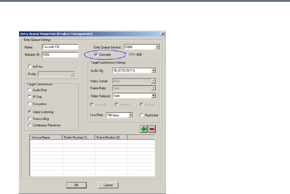
Defining Cascading Conferences
Polycom®, Inc. 261
3In the New Entry Queue dialog box, set the Entry Queue parameters and select the Cascade check
box.
For more details on the definition of new Entry Queues refer to the MGC Manager User’s Guide,
Volume II, Chapter 1, Ad Hoc Auto Cascading and Cascading Links.
4Click OK.
Creating the Dial-out Link between the Conference Running on the MGC and the
Conference Running on the RealPresence Collaboration Server
If the dialing is done from the MGC to the RealPresence Collaboration Server, you need to define the
cascaded link (dial-out participant) in the conference running on the MGC.
The dial-out string defined for the participant is the dialing string required to connect to the destination
conference via the Cascade-enabled Entry Queue defined on the RealPresence Collaboration Server
hosting the destination cascaded conference. The dial-out participant can be defined on the MGC as
template or assigned to the Meeting Room.
In the MGC Manager application, define a new participant as follows:
1In the Participant Properties - Identification dialog box, enter a Participant Name
2In the Connection Type field, select Dial-out.
3In the Interface Type list field, select H.323.
4There are two methods to define the dialing string to the other conference:
aUsing the MCU’s IP Address and the Alias string - Method A

Defining Cascading Conferences
Polycom®, Inc. 262
bUsing only the Alias string (requires a gatekeeper) - Method B
Method A
This method does not use any gatekeepers.
In the IP Address field, enter the IP address of the Signaling Host of the RealPresence
Collaboration Server hosting the destination conference.
In the Alias Name/Type field, enter the ID of the cascade-enabled Entry Queue (EQ), the Conference
ID and Password of the destination conference as follows:
<EQ ID>##<Destination Conference ID>##<Password> (Password is optional).
Method B
This method uses a gatekeeper.
In the Alias Name field, enter the Prefix of MCU B, EQ ID, Destination Conference ID, and Password,
as follows:
<MCU Prefix EQ ID>##<Conference ID>##<Password> (Password is optional)
5Click the Advanced tab and in the Node Type field, select Terminal.
For Example: 1002##12001##1234
Cascade-enabled
EQ ID
Destination
Confer
Password (optional)
For Example: 9251002##12001##1234
Cascade-enabled
EQ ID
Conference ID
Password (optional)MCU Prefix as
registered in
the
gatekeeper
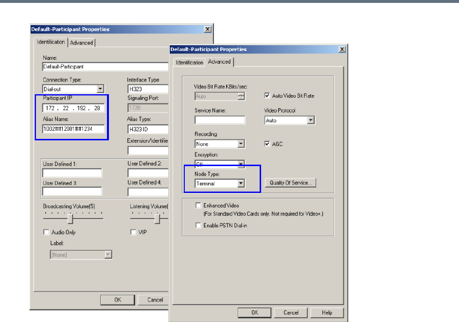
Defining Cascading Conferences
Polycom®, Inc. 263
6Click OK.
Defining the Cascade Enabled Entry Queue on the RealPresence Collaboration Server
If the dialing is done from the conference running on the MGC that is the Master MCU, a Cascade-enabled
Entry Queue must be defined on the RealPresence Collaboration Server setting it as Slave.
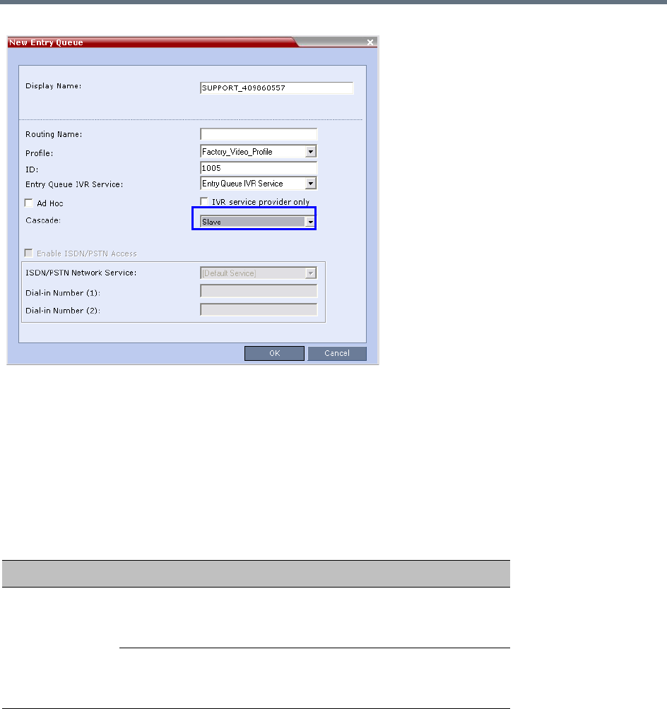
Defining Cascading Conferences
Polycom®, Inc. 264
For more details, see MGC to RealPresence Collaboration Server Cascading.
Defining the Cascading Conferences
The table below lists the line rates and the video settings that should be used when defining the conferences
on the MGC. The same line rates should be selected when defining the Conference Profiles on the
RealPresence Collaboration Server, as well as whether the conference is HD Video Switching. However,
the video settings will be automatically selected by the system.
In addition, the conference running on the MGC should be set as Meet Me Per Conference and select the
H.239 option in the Dual Stream Mode field. For more details on conference definition on the MGC, refer to
the MGC Manager User’s Guide, Volume I, Chapter 5.
Defining the Dial-out Participant on the RealPresence Collaboration Server
If the dialing is done from a conference running on the RealPresence Collaboration Server to the conference
running on the MGC, the dial-out participant is defined in the conference running on the RealPresence
Recommended Conference Line Rates for Cascaded Conferences
Topology Video Session Mode Conference Line Rate
MGC
RealPresence
Collaboration
Server
MGC - CIF 263
RealPresence Collaboration Server -
CIF 264 CP
768Kb/s, 2Mb/s
MGC - HD VSW
RealPresence Collaboration Server -
HD VSW
1.5Mb/s

Defining Cascading Conferences
Polycom®, Inc. 265
Collaboration Server, setting the Cascade field to Slave. This participant dials the Cascade-enabled Entry
Queue defined on the MGC.
To define the Dial-out Participant:
1Display the list of participants in the linked conference (Slave conference).
2In the Participant List pane, click the New Participant ( ) button.
The New Participant - General dialog box is displayed.
3In the Name field, enter a participant name.
4In the Dialing Direction field, select Dial-out.
5In the Type list field, verify that H.323 is selected.
6There are two methods to define the dialing string:
aUsing the MCU’s IP Address and the Alias string - Method A
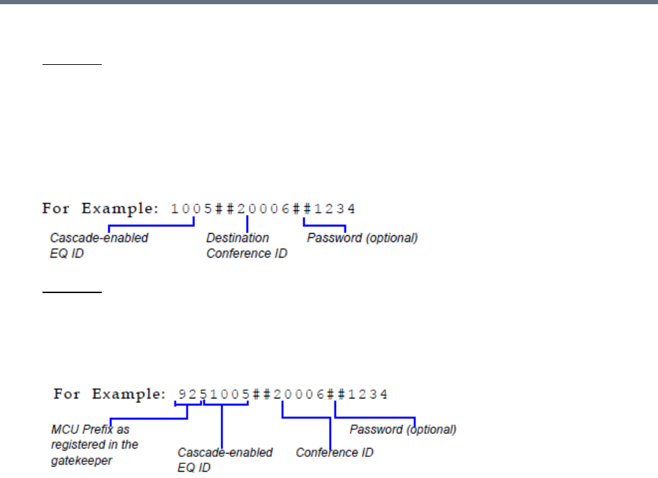
Defining Cascading Conferences
Polycom®, Inc. 266
bUsing only the Alias string (requires a gatekeeper) - Method B
Method A
This method does not used a gatekeeper.
In the IP Address field, enter the IP address of the MGC hosting the destination conference (Master
conference).
In the Alias Name/Type field, enter the ID of the cascade-enabled Entry Queue (EQ), the Conference
ID and Password of the destination conference (Master Conference) as follows:
<EQ ID>##<Destination Conference ID>##<Password> (Password is optional).
Method B
This method uses a gatekeeper.
In the Alias Name field, enter the MGC Prefix as registered in the gatekeeper, EQ ID, Destination
Conference ID, and Password, as follows:
<MGC Prefix EQ ID>##<Conference ID>##<Password> (Password is optional)
7Click the Advanced tab and in the Cascade field, select the Slave option.
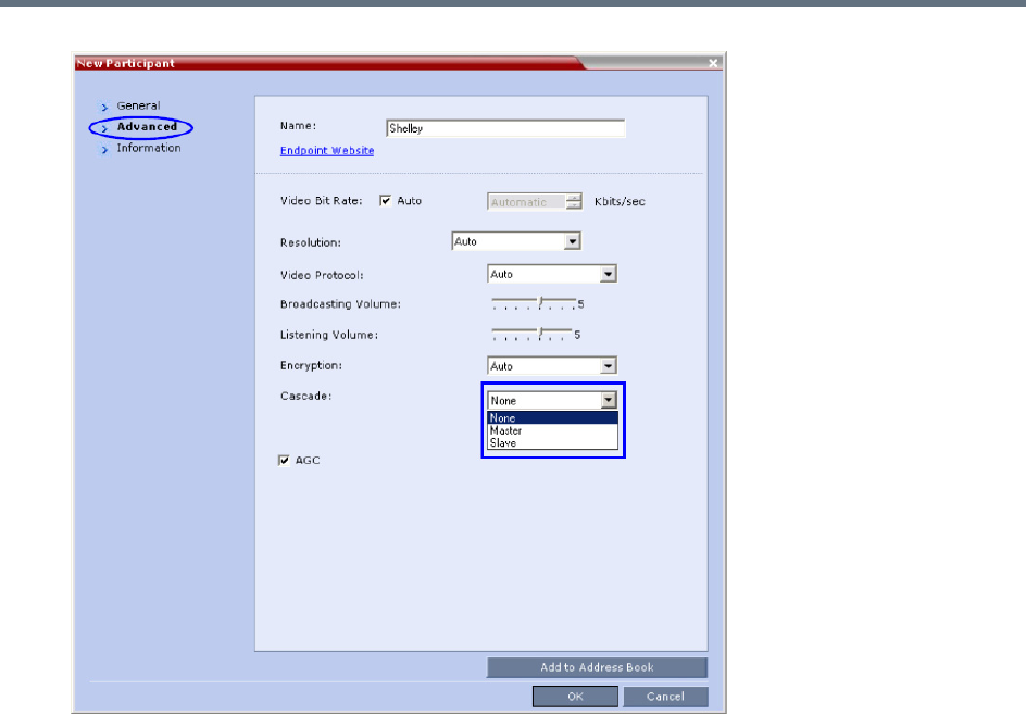
Defining Cascading Conferences
Polycom®, Inc. 267
8Click OK.
The cascade-enabled dial-out link is created and the system automatically dials out to connect the
participant to the local conference, as well as the destination conference on the MGC.

Polycom®, Inc. 268
Meeting Rooms
A Meeting Room is a conference saved on the MCU in passive mode, without using any of the system
resources. A Meeting Room is automatically activated when the first participant dials into it. Meeting Rooms
can be activated as many times as required. Once activated, a Meeting Room functions as any ongoing
conference.
The conferencing Mode of the Meeting Room is determined by the Profile assigned to it.
In SVC Conferencing Mode, dial-in is available as follows:
●AVC-capable endpoints (participants) can only connect to an AVC CP Meeting Room. When dialing
into SVC Only Meeting Room the calls fail.
●SVC-capable endpoints support both AVC and SVC video protocols. When dialing into SVC Only
conferences, they connect as SVC endpoints. When dialing into AVC CP Only conferences, they
connect as AVC endpoints.
●Both AVC and SVC endpoints can connect to a mixed CP and SVC conference.
In AVC Conferencing Mode, ISDN/PSTN participants can dial-in directly to a Meeting Room without
connection through an Entry Queue. Up to two numbers can be defined per conference provided that they
are from the same ISDN/PSTN Network Service. When a dial-in number is allocated to a Meeting Room,
the number cannot be deleted nor can the ISDN/PSTN Network Service be removed. The dial-in number
must be communicated to the ISDN or PSTN dial-in participants.
In AVC CP Conferences, dial-out participants can be connected to the conference automatically, or
manually. In the automatic mode the system calls all the participants one after the other. In the manual
mode, the Collaboration Server user or meeting organizer instructs the conferencing system to call the
participant. Dial-out participants must be defined (mainly their name and telephone number) and added to
the conference. This mode can only be selected at the conference/Meeting Room definition stage and
cannot be changed once the conference is ongoing.
A Meeting Room can be designated as a Permanent Conference.
For more information see Audio Algorithm Support.
The maximum of number of Meeting Rooms that can be defined is:
●RealPresence Collaboration Server (RMX) 1500/1800/2000 — 1000
●RealPresence Collaboration Server (RMX) 4000 — 2000
The system is shipped with four default Meeting Rooms:
Default Meeting Rooms List
Meeting Room Name ID Default Line Rate
Maple_Room 1001 384 Kbps
Oak_Room 1002 384 Kbps
Juniper_Room 1003 384 Kbps
Fig_Room 1004 384 Kbps
Meeting Rooms
Polycom®, Inc. 269
Use Time Out as DTMF Delimiter
Users are able to change the behavior of the policy of number collection for VMR Entry Queues,
Conference-IDs and Passwords, allowing a time-out to be used as a stop indicator for the input string.
In previous versions, a # input at the end of the input string indicated completion of the input.
The administrator can configure the system, using the ENABLE_DTMF_NUMBER_WO_DELIMITER
system flag to change the previous system behavior, allowing a time-out to be used as a stop indicator for
the string input for the local IVR, when the MCU collects the Conference-ID in the local Entry Queue or the
Password (chairperson or participant) while routed to the conference.
The flag must be manually added to the System Configuration and its value modified as follows:
A System Reset in not required for the flag setting to take effect.
For more information see,
Modifying System Flags
.
Meeting Rooms List
Meeting Rooms are listed in the Meeting Room list pane.
Flag Name
Value / Description
YES NO
ENABLE_DTMF_NUM
BER_WO_DELIMITER
If the timer expires, the received digits
validated even if there is no delimiter.
If the received number is not valid, the
system will prompt again for the number
according to number of retries. that are
configured.
This is the default setting for backward
compatibility.
If the timer expires because no delimiter
is received, the number input is not valid.
The system will prompt again for the
number according to number of retries.
that are configured.
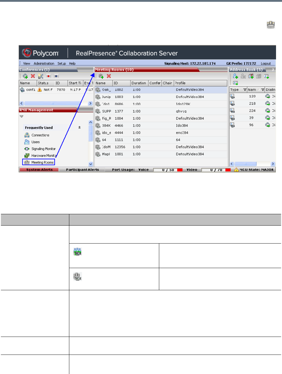
Meeting Rooms
Polycom®, Inc. 270
To list Meeting Rooms:
»In the RMX Management pane, in the Frequently Used list, click the Meeting Rooms button .
The Meeting Rooms list is displayed.
An active Meeting Room becomes an ongoing conference and is monitored in the same way as any
other conference.
The Meeting Room List columns include:
Meeting Rooms List Columns
Field Description
Display Name Displays the name and the icon of the Meeting Room in the Collaboration Server Web
Client.
(green)
An active video Meeting Room that was
activated when the first participant connected to
it.
(gray)
A passive video Meeting Room that is waiting to
be activated.
Routing Name The ASCII name that registers conferences, Meeting Rooms, Entry Queues and SIP
Factories in the various gatekeepers and SIP Servers. In addition, the Routing Name is
also:
•The name that endpoints use to connect to conferences.
•The name used by all conferencing devices to connect to conferences that must be
registered with the gatekeeper and SIP Servers.
ID Displays the Meeting Room ID. This number must be communicated to H.323
conference participants to enable them to dial in.
Duration Displays the duration of the Meeting Room in hours using the format HH:MM
(default 01:00).

Meeting Rooms
Polycom®, Inc. 271
Use Time Out as DTMF Delimiter
Users are able to change the behavior of the policy of number collection for VMR Entry Queues,
Conference-IDs and Passwords, allowing a time-out to be used as a stop indicator for the input string.
In previous versions, a # input at the end of the input string indicated completion of the input.
Conference Password The password to be used by
participants to access the Meeting
Room. If blank, no password is
assigned to the conference. This
password is valid only in
conferences that are configured to
prompt for a conference password
in the IVR Service. The Collaboration Server can be configured to
automatically generate conference and
chairperson passwords when these fields are
left blank. For more information, see the
Automatic Password Generation Flags.
Chairperson Password Displays the password to be used
by the users to identify themselves
as Chairpersons. They are granted
additional privileges. If left blank,
no chairperson password is
assigned to the conference. This
password is valid only in
conferences that are configured to
prompt for a chairperson
password.
Profile Displays the name of the Profile assigned to the Meeting Room. For more information,
see Defining New Profiles.
SIP Registration The status of registration with the SIP server:
• Not configured - Registration with the SIP Server was not enabled in the
Conference Profile assigned to this conferencing Entity. In Multiple Networks
configuration, If one service is not configured while others are configured and
registered, the status reflects the registration with the configured Network Services.
The registration status with each SIP Server can be viewed in the Properties -
Network Services dialog box of each conferencing entity.
When SIP registration is not enabled in the conference profile, the Collaboration
Server's registering to SIP Servers will each register with a URL derived from its
own signaling address. In Collaboration Server 1500/2000/4000, this unique URL
replaces the non-unique URL, dummy_tester, used in previous versions.
•Failed - Registration with the SIP Server failed. This may be due to incorrect
definition of the SIP server in the IP Network Service, or the SIP server may be
down, or any other reason the affects the connection between the Collaboration
Server or the SIP Server to the network.
•Registered - the conferencing entity is registered with the SIP Server.
• Partially Registered - This status is available only in Multiple Networks
configuration, when the conferencing entity failed to register to all the required
Network Services if more than one Network Service was selected.
Meeting Rooms List Columns
Field Description
Meeting Rooms
Polycom®, Inc. 272
The administrator can configure the system, using the ENABLE_DTMF_NUMBER_WO_DELIMITER
system flag to change the previous system behavior, allowing a time-out to be used as a stop indicator for
the string input for the local IVR, when the MCU collects the Conference-ID in the local Entry Queue or the
Password (chairperson or participant) while routed to the conference.
The flag must be manually added to the System Configuration and its value modified as follows:
A System Reset in not required for the flag setting to take effect.
For more information see
Modifying System Flags
.
Meeting Room Toolbar & Right-click Menu
The Meeting Room toolbar and right-click menus provide the following functionality:
Flag Name
Value / Description
YES NO
ENABLE_DTMF_NUM
BER_WO_DELIMITER
If the timer expires, the received digits
validated even if there is no delimiter.
If the received number is not valid, the
system will prompt again for the number
according to number of retries. that are
configured.
This is the default setting for backward
compatibility.
If the timer expires because no delimiter
is received, the number input is not valid.
The system will prompt again for the
number according to number of retries.
that are configured.
Meeting Room Toolbar and Right-click Menus
Toolbar
button Right-click menu Description
New Meeting Room Select this button to create a new Meeting Room.
Delete Meeting Room Select any Meeting Room and then click this button to delete the
Meeting Room.
Dial out to AVC participants assigned to a Meeting Room will only start when the dial in participant
who has activated it has completed the connection process and the Meeting Room has become an
ongoing conference.
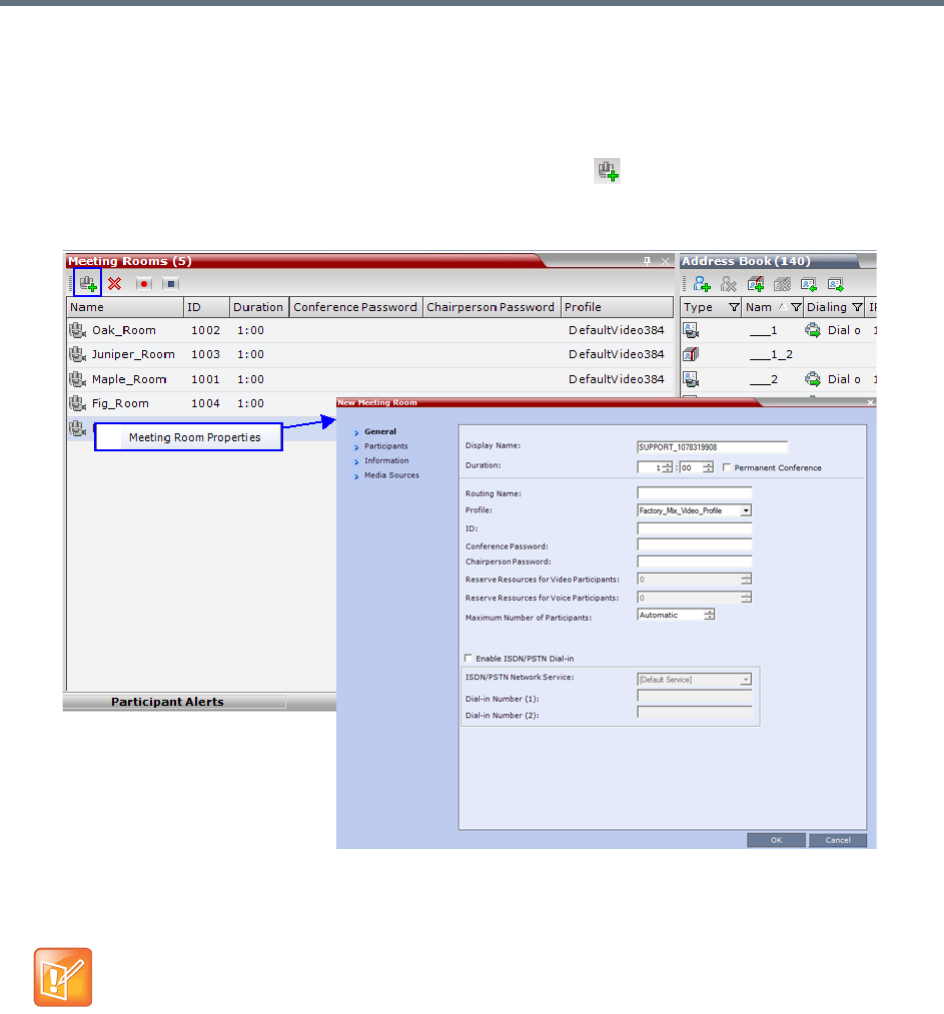
Meeting Rooms
Polycom®, Inc. 273
Creating a New Meeting Room
To create a new meeting room:
●In the Meeting Rooms pane, click the New Meeting Room button or right-click an empty area
in the pane, and select New Meeting Room.
The New Meeting Room dialog box is displayed.
The definition procedure is the same as for the new conference (with the exception of Reserved
Resources for Audio and Video participants in RealPresence Collaboration Server 1500/2000/4000
only).
Microsoft Lync users can connect a Collaboration Server Meeting Room to a conference running on
the Microsoft A/V MCU. This allows Collaboration Server Lync users to connect with a conference in
progress on the A/V MCU and be an active participant in the conference.
Microsoft Lync is not supported by Collaboration Server (RMX) 1800-0.
For more information, see Connecting a Collaboration Server Meeting Room to a Microsoft AV-MCU
Conference.
If SIP Factories are being used do not assign a Meeting Room the ID 7001. This ID is reserved for
the default SIP Factory.

Polycom®, Inc. 274
Entry Queues, Ad Hoc Conferences and
SIP Factories
Entry Queues
An Entry Queue (EQ) is a special routing lobby to access conferences. Participants connect to a single-dial
lobby and are routed to their destination conference according to the Conference ID they enter. The Entry
Queue remains in a passive state when there are no callers in the queue (in between connections) and is
automatically activated once a caller dials its dial-in number.
Participants can be moved from the Entry Queue and the destination conference if both conferencing
entities are set to the same conferencing parameters: Conferencing Mode, Line rate and video parameters.
For example, participants can be moved from SVC Only Entry Queue to SVC Only conference, or from a
mixed CP and SVC Entry Queue to a mix CP and SVC conference, from CP only Entry Queue to CP only
conference.
The maximum of number of Entry Queues that can be defined is:
●RealPresence Collaboration Server (RMX) 1500/1800/2000 — 40
●RealPresence Collaboration Server (RMX) 4000 — 80
The parameters (bit rate and video properties) with which the participants connect to the Entry Queue and
later to their destination conference are defined in the Conference Profile that is assigned to the Entry
Queue. For example, if the Profile Bit Rate is set to 384kbps, all endpoints connect to the Entry Queue and
later to their destination conference using this bit rate even if they are capable of connecting at higher bit
rates.
An Entry Queue IVR Service must be assigned to the Entry Queue to enable the voice prompts guiding the
participants through the connection process. The Entry Queue IVR Service also includes a video slide that
is displayed to the participants while staying in the Entry Queue (during their connection process).
Different Entry Queues can be created to accommodate different conferencing modes, conferencing
parameters (by assigning different Profiles) and prompts in different languages (by assigning different Entry
Queue IVR Services).
For more information, see IVR Services List.
The Entry Queue can also be used for Ad Hoc conferencing. If the Ad Hoc option is enabled for the Entry
Queue, when the participant enters the target conference ID the system checks whether a conference with
that ID is already running on the MCU. If not, the system automatically creates a new ongoing conference
with that ID. For more information about Ad Hoc conferencing, see Ad Hoc Conferencing.
An Entry Queue can be designated as Transit Entry Queue to which calls with dial
strings containing
incomplete or incorrect conference routing information are transferred.
For more information, see Transit
Entry Queue.
To enable ISDN/PSTN participants to dial in to the Entry Queue, an ISDN/PSTN dial-in number must be
assigned to the Entry Queue. Up to two dial-in numbers can be assigned to each Entry Queue. The dial-in
numbers must be allocated from the dial-in number range defined in the ISDN/PSTN Network Service. You
can allocate the two dial-in numbers from the same ISDN/PSTN Network Service or from two different
ISDN/PSTN Network Services. The dial-in number must be communicated to the ISDN or PSTN dial-in
participants.
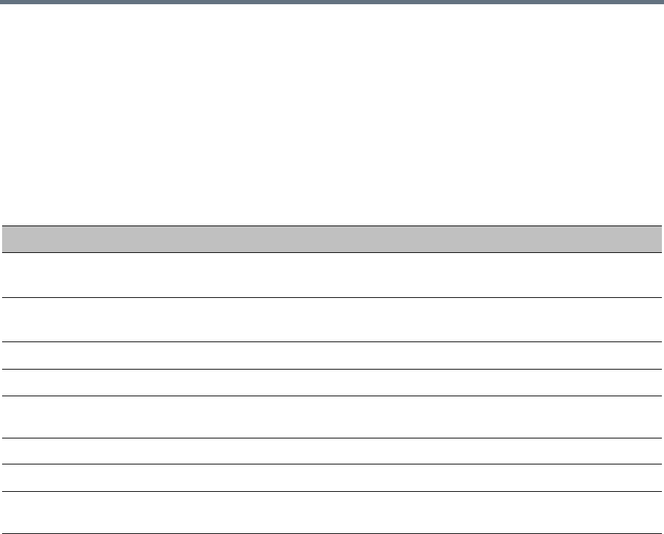
Entry Queues, Ad Hoc Conferences and SIP Factories
Polycom®, Inc. 275
The Entry Queue can also be used as part of the Gateway to Polycom® RealPresence DMA solution for
connecting Audio only PSTN, ISDN, SIP and H.323 endpoints to RealPresence DMA™ system.
Gateway functionality is not supported by Collaboration Server (RMX) 1800-0.
For more information, see Dialing to Polycom® RealPresence DMA System.
Default Entry Queue properties
The system is shipped with a default Entry Queue whose properties are shown in the following table.
Defining a New Entry Queue
You can modify the properties of the default Entry Queue and define additional Entry Queues to suit different
conferencing requirements.
Default Entry Queue Properties
Parameter Value
Display Name DefaultEQ
The user can change the name if required.
Routing Name DefaultEQ
The default Routing Name cannot be changed.
ID 1000
Profile name Factory_Video_Profile. Profile Bit Rate is set to 384 Kbps.
Entry Queue Service Entry Queue IVR Service. This is default Entry Queue IVR Service shipped with the
system and includes default voice messages and prompts in English.
Ad Hoc Enabled
Cascade None (Disabled)
Enable ISDN/PSTN
Access
Disabled. You can modify the properties of this Entry Queue to enable ISDN/PSTN
participants to dial-in to a conference. Up to two dial-in numbers can be assigned.
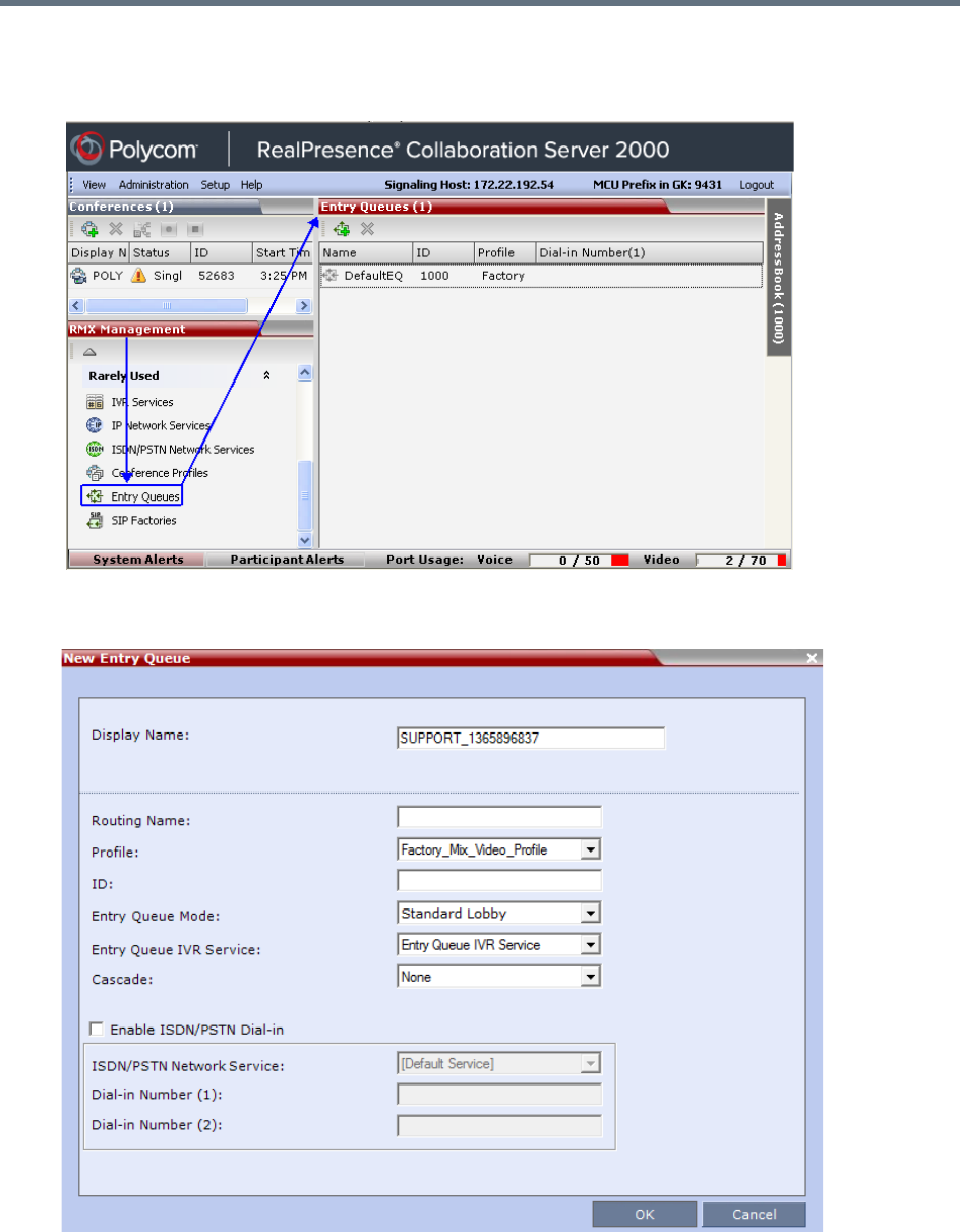
Entry Queues, Ad Hoc Conferences and SIP Factories
Polycom®, Inc. 276
To define a new Entry Queue:
1In the RMX Management pane, In the Rarely Used menu, click Entry Queues.
2In the Entry Queues list pane, click the New Entry Queue button.
The New Entry Queue dialog box opens.

Entry Queues, Ad Hoc Conferences and SIP Factories
Polycom®, Inc. 277
3Define the following parameters:
Entry Queue Definitions Parameters
Option Description
Display Name The Display Name is the conferencing entity name in native language character
sets to be displayed in the Collaboration Server Web Client.
In conferences, Meeting Rooms, Entry Queues and SIP factories the system
automatically generates an ASCII name for the Display Name field that can be
modified using Unicode encoding.
•English text uses ASCII encoding and can contain the most characters
(length varies according to the field).
•European and Latin text length is approximately half the length of the
maximum.
•Asian text length is approximately one third of the length of the maximum.
The maximum length of text fields also varies according to the mixture of
character sets (Unicode and ASCII).
Maximum field length in ASCII is 80 characters. If the same name is already
used by another conference, Meeting Room or Entry Queue, the Collaboration
Server displays an error message requesting you to enter a different name.
Routing Name Enter a name using ASCII text only. If no Routing Name is entered, the system
automatically assigns a new name as follows:
•If an all ASCII text is entered in Display Name, it is used also as the Routing
Name.
•If any combination of Unicode and ASCII text (or full Unicode text) is entered
in Display Name, the ID (such as Conference ID) is used as the Routing
Name.
Profile Select the Profile to be used by the Entry Queue.
The default Profile is selected by default. This Profile determines the Bit Rate
and the video properties with which participants connect to the Entry Queue and
destination conference.
To connect to a Video Switching conference via Entry Queue, the Profile
assigned to the Entry Queue must be set to Video Switching. It is recommended
to use the same profile for both the destination conference and Entry Queue.
In Ad Hoc conferencing, it is used to define the new conference properties.
ID Enter a unique number identifying this conferencing entity for dial in. Default
string length is 4 digits.
If you do not manually assign the ID, the MCU assigns one after the completion
of the definition. The ID String Length is defined by the flag
NUMERIC_CONF_ID_LEN in the System Configuration.

Entry Queues, Ad Hoc Conferences and SIP Factories
Polycom®, Inc. 278
Entry Queue Mode Select the mode for the Entry Queue
Standard Lobby (default) - When selected, the Entry Queue is used as a
routing lobby to access conferences. Participants connect to a single-dial lobby
and are routed to their destination conference according to the Conference ID
they enter.
Ad Hoc - Select this option to enable the Ad Hoc option for this Entry Queue. In
this mode, when the participant enters the target conference ID the system
checks whether a conference with that ID is already running on the MCU. If not,
the system automatically creates a new ongoing conference with that ID.
IVR Only Service Provider - When selected, designates this Entry Queue as a
special Entry Queue that provides IVR Services to SIP calls on behalf of the
RealPresence DMA system. The IVR Only Service Provider Entry Queue does
not route the SIP calls to a target conference. Instead the RealPresence DMA
system handles the call. For more details, see IVR Provider Entry Queue
(Shared Number Dialing).
External IVR Control - IVR Services can be controlled externally from an
application server (such as the DMA) supporting the MCCF-IVR (Media Control
Channel Framework-Interactive Voice Response) package.
When selected, the connection process of the participant to the conference via
the Virtual Entry Queue is controlled and managed by an external IVR service of
an application server (for example, DMA).
Entry Queue IVR Service The default Entry Queue IVR Service is selected. If required, select an alternate
Entry Queue IVR Service, which includes the required voice prompts, to guide
participants during their connection to the Entry Queue.
Cascade Set this field to None for all Entry Queues other than cascading.
If this Entry Queue is used to connect dial-in cascaded links, select Master or
Slave depending on the Master/Slave relationship in the Cascading topology.
Set this field to Master if:
•The Entry Queue is defined on the MCU on level 1 and the dialing is done
from level 2 to level 1.
•The Entry Queue is defined on the MCU on level 2 and the dialing is done
from level 3 to level 2.
Set this field to Slave if the Entry Queue is defined on the MCU on level 2
(Slave) and the dialing is done from MCU level 1 to level 2.
Enable ISDN/PSTN
Access
Select this check box to allocate dial-in numbers for ISDN/PSTN connections.
To define the first dial-in number using the default ISDN/PSTN Network Service,
leave the default selection. When the Entry Queue is saved on the MCU, the
dial-in number will be automatically assigned to the Entry Queue. This number
is taken from the dial-in numbers range in the default ISDN/PSTN Network
Service.
ISDN/PSTN Network
Service
The default Network Service is automatically selected. To select a different
ISDN/PSTN Network Service in the service list, select the name of the Network
Service.
Entry Queue Definitions Parameters
Option Description
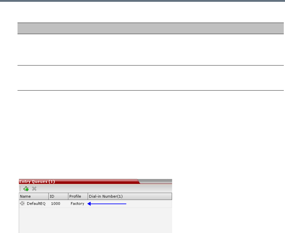
Entry Queues, Ad Hoc Conferences and SIP Factories
Polycom®, Inc. 279
4Click OK.
The new Entry Queue is added to the Entry Queues list.
Listing Entry Queues
To view the list of Entry Queues:
»In the RMX Management pane- Rarely Used menu, click Entry Queues.
The Entry Queues are listed in the Entry Queues pane.
You can double-click an Entry Queue to view its properties.
Modifying the EQ Properties
To modify the EQ:
»In the Entry Queues pane, either double-click or right-click, and select Entry Queue Properties of
the selected Entry Queue in the list.
The Entry Queue Properties dialog box is displayed. All the fields may be modified except Routing
Name.
Transit Entry Queue
A Transit Entry Queue is an Entry Queue to which calls with dial
strings containing incomplete or incorrect
conference routing information are transferred.
Dial-in Number (1) Leave this field blank to let the system automatically assign a number from the
selected ISDN/PSTN Network Service. To manually define a dial-in number,
enter a required number from the dial-in number range defined for the selected
Network Service.
Dial-in Number (2) By default, the second dial-in number is not defined. To define a second-dial-in
number, enter a required number from the dial-in number range defined for the
selected Network Service.
Entry Queue Definitions Parameters
Option Description
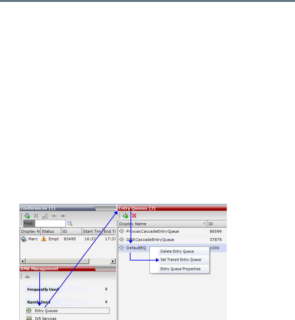
Entry Queues, Ad Hoc Conferences and SIP Factories
Polycom®, Inc. 280
IP Calls are routed to the Transit Entry Queue when:
●A gatekeeper is not used, or where calls are made directly to the Collaboration Server’s Signaling IP
Address, with incorrect or without a Conference ID.
●When a gatekeeper is used and only the prefix of the Collaboration Server is dialed, with incorrect or
without a Conference ID.
●When the dialed prefix is followed by an incorrect conference ID.
When no Transit Entry Queue is defined, all calls containing incomplete or incorrect conference routing
information are rejected by the Collaboration Server.
In the Transit Entry Queue, the Entry Queue IVR Service prompts the participant for a destination
conference ID. Once the correct information is entered, the participant is transferred to the destination
conference.
Setting a Transit Entry Queue
The Collaboration Server factory default settings define the Default Entry Queue also as the Transit Entry
Queue. You can designate another Entry Queue as the Transit Entry Queue.
Only one Transit Entry Queue may be defined per Collaboration Server and selecting another Entry Queue
as the Transit Entry Queue automatically cancels the previous selection.
To designate an Entry Queue as Transit Entry Queue:
1In the RMX Management pane, Rarely Used list, click Entry Queues.
2In the Entry Queues list, right-click the Entry Queue entry, and then click Set Transit Entry Queue.
The Entry Queue selected as Transit Entry Queue is displayed in bold.
To cancel the Transit Entry Queue setting:
1In the RMX Management pane, Rarely Used list, click Entry Queues.
2In the Entry Queues list, right-click the Transit Entry Queue entry, and then click Cancel Transit
Entry Queue.

Entry Queues, Ad Hoc Conferences and SIP Factories
Polycom®, Inc. 281
IVR Provider Entry Queue (Shared Number Dialing)
In an environment that includes a RealPresence DMA system, the Collaboration Server Entry Queue can
be configured to provide the IVR Services on behalf of the RealPresence DMA system to SIP endpoints. It
displays the Welcome Slide, plays the welcome message and retrieves the destination conference ID that
is entered by the participant using DTMF codes.
To enable this feature, a special Entry Queue that is defined as IVR Only Service Provider is created. This
Entry Queue does not forward calls to conferences running on the Collaboration Server and its main
functionality is to provide IVR services.
Call Flow
The SIP participant dials the DMA Virtual Entry Queue number, for example 1000@dma.polycom.com.
The DMA forwards the SIP call to the Collaboration Server, to a special Entry Queue that is configured as
IVR Only Service Provider. The participant is prompted to enter the conference ID using DTMF codes.
Once the participant enters the conference ID, the conference ID is forwarded to the DMA, enabling the
DMA to connect the SIP endpoint to the destination conference or create a new conference and connect
the participant to that conference.
Guidelines for setting the Entry Queue as IVR Provider
●An Entry Queue defined as IVR Only Service Provider does not route the SIP call to a target
conference and it cannot be used to route calls on the Collaboration Server. In such a configuration,
the DMA handles the calls. Therefore, normal Entry Queues must be defined separately.
●Operator Assistance must be disabled in the IVR Service assigned to this Entry Queue.
●Only the conference ID prompts should be configured. Other prompts are not supported in IVR Only
Service Provider configuration.
●PSTN, ISDN, and H.323 calls to this Entry Queue are rejected.
●The DMA must be configured to locate the IVR Only Service Provider Entry Queue on the
Collaboration Server. To locate the Entry Queue the DMA requires the Entry Queue’s ID number and
the Collaboration Server Signaling IP address (xxx.xx.xxx.xx).
Configuring the Collaboration Server as IVR Provider
Entry Queue IVR Service
If required, create a special Entry Queue IVR Service in which the Operator Assistance option is disabled,
and only the Conference ID prompts are enabled.
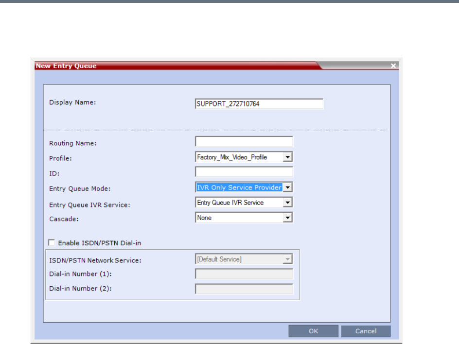
Entry Queues, Ad Hoc Conferences and SIP Factories
Polycom®, Inc. 282
Entry Queue
»In the New Entry Queue dialog box, Entry Queue Mode list, select IVR Only Service Provider.
Enter the Entry Queue ID to be used by the DMA for forwarding the SIP calls to this Entry Queue.
Select the special Entry Queue IVR Service if one was created.
The Cascade and Enable ISDN/PSTN Dial-in options should not be enabled with this type of
Entry Queue.
Using External IVR Services via the MCCF-IVR Package
IVR Services can be controlled externally from an application server supporting the MCCF-IVR (Media
Control Channel Framework-Interactive Voice Response) package. The external IVR service is currently
being implemented with the integration of the Polycom RealPresence Virtualization Manager (DMA) as the
application server. When the application server is deployed in the enterprise environment and the Polycom
RealPresence Collaboration Server (MCU) is deployed as a media server, the external IVR service can be
used to play audio messages, display slides, and collect DTMF input from the participant. The external IVR
service is managed by the application server at the pre-conference phase when the participant is placed
into a special external IVR-controlled Entry Queue in the Collaboration Server (MCU), collecting information
before connecting to the conference.
The external IVR-controlled Entry Queue plays recorded voice messages or sends video slides such as
splash screens to the participant and collects DTMF input from the participant such as conference ID and
conference password for various functions.

Entry Queues, Ad Hoc Conferences and SIP Factories
Polycom®, Inc. 283
IVR media files, WAV for voice messages and JPG for video slides, are stored on the application server. In
order to provide external IVR control, a TCP-based MCCF channel is created between the application
server and the media server. Because of real-time considerations, when the MCCF channel is established,
the application server notifies the media server about the media files. The media server downloads the
media files. The media server is notified by the application server when to download new or updated media
files.
When the call has completed the pre-conference phase in the external IVR-controlled Entry Queue, the
application server disconnects the call from the Entry Queue and routes the call to an ongoing conference
or creates a new VMR.
Call Flows
The external IVR-controlled Entry Queue can be initiated for various types of calls from SIP endpoints such
as standalone endpoints and Cisco TIP endpoints. Standalone endpoints are SIP or H.264 TIP endpoints.
These endpoints can include HDX systems, multiple Telepresence (ITP) screens, and RealPresence
Desktop client applications.
Call Flow for Standalone SIP Endpoints
The following describes how a standalone SIP endpoint call is placed into the IVR-controlled Entry Queue
and is then connected to a conference:
1A SIP call is routed through the application server to the IVR-controlled Entry Queue.
2The MCU answers the call and waits for the IVR media file requests from the application server. The
MCU does not control the call while the call is in the Entry Queue.
3The application server may request, through the MCCF channel - IVR package, to play an audio file
and display a slide. When the audio file has finished playing, the MCU notifies the application server
that the audio file has been played for the call.
4The application server may request, through the MCCF channel - IVR package, to collect DTMF
input such as a conference ID or password, from the caller. The DTMF input is transferred from the
MCU to the application server. When the application server receives the DTMF input, it validates the
input for the required conference ID or password. If the input is incorrect, the application server will
request the MCU to replay the audio file and collect the DTMF input again. The MCU transfers the
DTMF input to the application server for revalidation.
5When the application server has completed the pre-conference IVR, the application server routes
the call to a VMR with the collected password appended to the following dial string:
<conf-id>**<password>@mcu-sig-ip.
The call is disconnected from the application server. The MCU now has control of the call.
6The call is transferred to a conference, which can reside on another MCU.
Call Flow for Standalone TIP Endpoints
The following describes how a standalone TIP endpoint call is placed into the IVR-controlled Entry Queue
and is then connected to a conference:
1A TIP call is routed through the application server to the IVR-controlled Entry Queue. TIP endpoints
can either have a single screen or multiple screens.
2The MCU answers the call and waits for the IVR media file requests from the application server. The
MCU does not control the call while the call is in the Entry Queue.

Entry Queues, Ad Hoc Conferences and SIP Factories
Polycom®, Inc. 284
3The application server may request, through the MCCF channel - IVR package, to play an audio file
and display a video slide. When the TIP endpoint uses multiple screens, the video slide is displayed
on the main screen only. When the audio file has finished playing, the MCU notifies the application
server that the audio file has been played for the call.
4The application server may request, through the MCCF channel - IVR package, to collect DTMF
input such as a conference ID or password, from the caller. When the TIP endpoint uses multiple
screens, the DTMF input is collected only once from the main screen. The DTMF input is transferred
from the MCU to the application server. When the application server receives the DTMF input, it
validates the input for the required conference ID or password. Because TIP uses DTLS, it can
optionally enable re-keying of DTMF input and the calls to the Entry Queue and the conference can
be encrypted.
5When the application server has completed the pre-conference IVR, the application server routes
the call to a VMR with the collected password appended to the following dial string:
<conf-id>**<password>@mcu-sig-ip.
The call is disconnected from the application server. The MCU now has control of the call.
6The call is transferred to a conference, which can reside on another MCU.
Call Flow for TIP Endpoints from a Polycom ITP System
The following describes how a TIP call from Cisco TPS endpoints or TIP calls from a Polycom ITP system
working as a TIP call is placed into the IVR-controlled Entry Queue and is then connected to a conference:
1A TIP call is routed through the application server to the IVR-controlled Entry Queue.
2The MCU answers the call and waits for the IVR media file requests from the application server. The
MCU does not control the call while the call is in the Entry Queue.
3While the call is in the Entry Queue, video is only displayed on the main screen.
4DTMF input is collected only once from the main screen. Because TIP uses DTLS, it can optionally
enable re-keying of DTMF input and the calls to the Entry Queue and the conference can be
encrypted.
5When the application server has completed the pre-conference IVR, the application server routes
the call to a VMR with the collected password appended to the following dial string:
<conf-id>**<password>@mcu-sig-ip. The MCU now has control of the call.
The call is transferred to a conference, which can reside on another MCU.
Guidelines for Using External IVR Services via the MCCF-IVR Package
●Only AVC SIP and TIP protocols are supported.
●MCCF channels support both IPV4 and IPV6.
●When the MCCF channel is disconnected, an alarm is displayed and all external IVR files are deleted.
When the MCCF channel is reconnected, the external IVR files are sent to the MCU.
●When the Collaboration Server (MCU) is restarted, all existing external IVR files are deleted. When
the MCCF channel connects to the Collaboration Server, the external IVR file are sent to the
Collaboration Server.
●H.323 and ISDN protocols are not supported.
●Video Switching conferences do not support the TIP protocol
●TIP-based conferencing does not support the following features during conferences:
Gathering phase

Entry Queues, Ad Hoc Conferences and SIP Factories
Polycom®, Inc. 285
Skin display
Text messaging using Message Overlay
Site Name display
PCM
Click&View
●To play audio messages and display the welcome slide during the participant connection to the
conference via the Virtual Entry Queue, the Media files have to meet the following requirements (as
defined in the Entry Queue IVR Service):
Audio messages: WAV files - PCM, 16 KHz, 16 bit, Mono
Video slides: JPG files - 1920 x 1088 resolution
Configuring the MCU to Support External IVR Services via the MCCF-IVR
The support of External IVR Services via the MCCF-IVR package is enabled by default in the Collaboration
Server (RMX) systems, by the flag ENABLE_MCCF which is set to YES.
However, in Ultra Secure Mode and in secured environments where the External IVR Services via the
MCCF-IVR package is not required and unused ports should be closed, this flag should be set to NO.
To change this flag value from YES to No, you must first add it to the System Configuration. For more details,
see .
Configuring the Entry Queue to Use External IVR Services
The Entry Queue can be configured to place a call in the external IVR-controlled Entry Queue.
To configure the Entry Queue for External IVR Services:
1In the RMX Management pane, click Entry Queues.
2In the Entry Queues pane, click the New Entry Queue icon.
The New Entry Queue dialog box is displayed.
3In the Display Name field, type an appropriate display name for the Entry Queue.
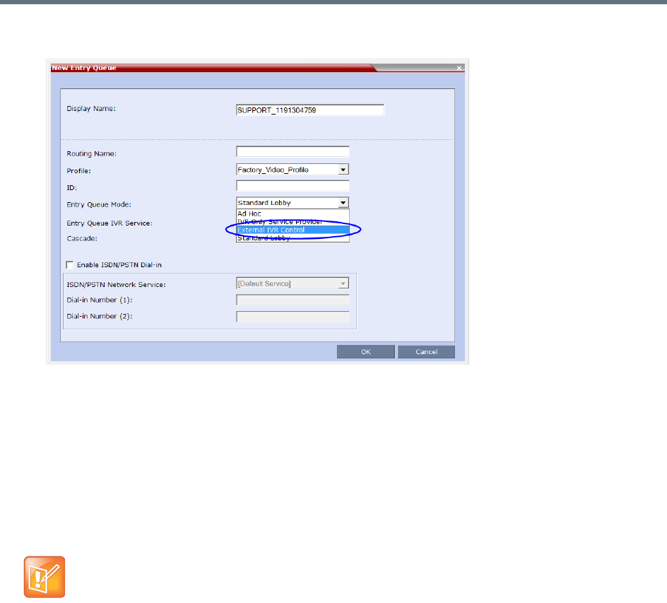
Entry Queues, Ad Hoc Conferences and SIP Factories
Polycom®, Inc. 286
4In the Entry Queue Mode field, select External IVR Control from the available options.
When External IVR Control is selected, the connection process of the participant to the conference
via the Virtual Entry Queue is controlled and managed by an external IVR service of an application
server (for example, DMA).
5Click OK.
SIP Factories
A SIP Factory is a conferencing entity that enables SIP endpoints to create Ad Hoc conferences. The
system is shipped with a default SIP Factory, named DefaultFactory.
.
When a SIP endpoint calls the SIP Factory URI, a new conference is automatically created based on the
Profile parameters, and the endpoint joins the conference.
The SIP Factory URI must be registered with the SIP server to enable routing of calls to the SIP Factory. To
ensure that the SIP factory is registered, the option to register Factories must be selected in the Default IP
Network Service.
The maximum of number of SIP Factories that can be defined is 40.
Creating SIP Factories
To create a new SIP Factory:
1In the RMX Management pane, Rarely Used list, click SIP Factories.
The default SIP Factory uses the conferencing ID 7001. If a SIP Factory is being used do not assign
this ID to any conferencing entity, including conferences, reservations, and meeting rooms.
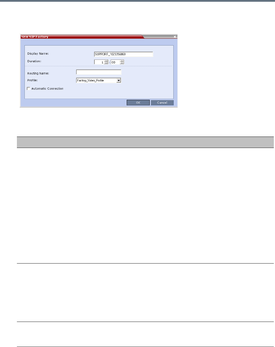
Entry Queues, Ad Hoc Conferences and SIP Factories
Polycom®, Inc. 287
2In the SIP Factories list pane, click the New SIP Factory button.
The New Factory dialog box opens.
3Define the following parameters:
:
New Factory Properties
Option Description
Display Name Enter the SIP Factory name that will be displayed.
The Display Name is the conferencing entity name in native language character
sets to be displayed in the Collaboration Server Web Client.
In conferences, Meeting Rooms, Entry Queues and SIP factories the system
automatically generates an ASCII name for the Display Name field that can be
modified using Unicode encoding.
•English text uses ASCII encoding and can contain the most characters
(length varies according to the field).
•European and Latin text length is approximately half the length of the
maximum.
•Asian text length is approximately one third of the length of the maximum.
The maximum length of text fields also varies according to the mixture of
character sets (Unicode and ASCII).
Maximum field length in ASCII is 80 characters. If the same name is already
used by another conference, Meeting Room or Entry Queue, the Collaboration
Server displays an error message requesting you to enter a different name.
Routing Name The Routing Name is defined by the user, however if no Routing Name is
entered, the system will automatically assign a new name when the Profile is
saved as follows:
•If an all ASCII text is entered in Display Name, it is used also as the Routing
Name.
•If any combination of Unicode and ASCII text (or full Unicode text) is entered
in Display Name, the ID (such as Conference ID) is used as the Routing
Name.
Profile The default Profile is selected by default. If required, select the conference
Profile from the list of Profiles defined in the MCU.
A new conference is created using the parameters defined in the Profile.
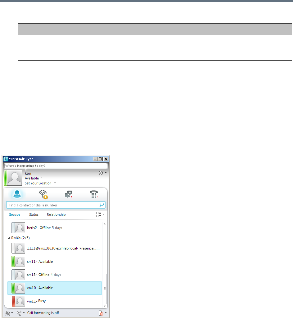
Entry Queues, Ad Hoc Conferences and SIP Factories
Polycom®, Inc. 288
4Click OK.
The new SIP Factory is added to the list.
SIP Registration & Presence for Entry Queues and SIP
Factories with SIP Servers
Entry Queues and SIP Factories can be registered with SIP servers. This enables Office Communication
Server or Lync server client users to see the availability status (Available, Offline, or Busy) of these
conferencing entities, and to connect to them directly from the Buddy List.
Guidelines for registering Entry Queues and SIP Factories with SIP Servers
●The Entry Queue or SIP Factory must be added to the Active Directory as a User.
●SIP Registration must be enabled in the Profile assigned to the Entry Queue or SIP Factory. For more
information see Defining New Profiles.
Automatic Connection Select this check box to immediately accept the conference creator endpoint to
the conference. If the check box is cleared, the endpoint is redirected to the
conference and then connected.
New Factory Properties
Option Description
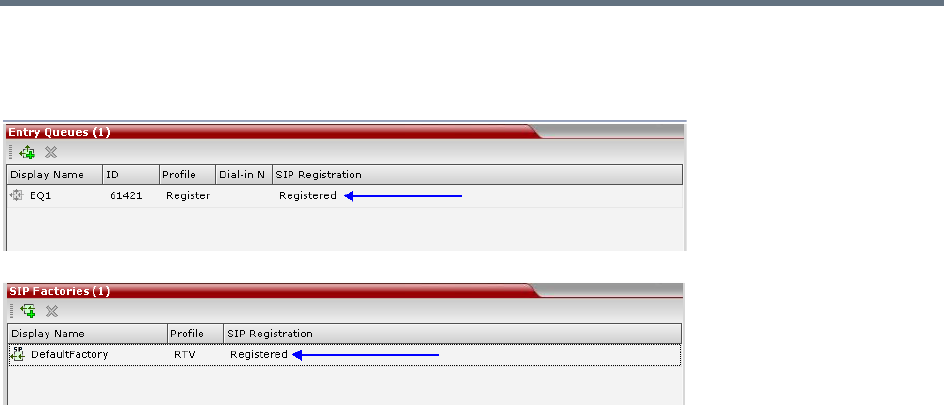
Entry Queues, Ad Hoc Conferences and SIP Factories
Polycom®, Inc. 289
Monitoring Registration Status
The SIP registration status can be viewed in the Entry Queue or SIP Factory list panes.
The following statuses are displayed:
●Not configured - Registration with the SIP Server was not enabled in the Conference Profile
assigned to the Entry Queue or SIP Factory.
When SIP registration is not enabled in the conference profile, the Collaboration Server's registering
to SIP Servers will each register with an URL derived from its own signaling address. In Collaboration
Server 1500/2000/4000, this unique URL replaces the non-unique URL, dummy_tester, used in
previous versions.
●Failed - Registration with the SIP Server failed.
This may be due to incorrect definition of the SIP server in the IP Network Service, or the SIP Server
may be down, or any other reason the affects the connection between the Collaboration Server or the
SIP Server to the network.
●Registered - The conferencing entity is registered with the SIP Server.
●Partially Registered - This status is available only in Multiple Networks configuration, when the
conferencing entity failed to register to all the required Network Services, if more than one Network
Service was selected for Registration.
Ad Hoc Conferencing
The Entry Queue can also be used for Ad Hoc conferencing. If the Ad Hoc option is enabled for the Entry
Queue, when the participant enters the target conference ID the system checks whether a conference with
that ID is already running on the MCU. If not, the system automatically creates a new ongoing conference
with that ID. The conference parameters are based on the Profile linked to the Entry Queue. As opposed to
Meeting Rooms, that are predefined conferences saved on the MCU, Ad Hoc conferences are not stored
on the MCU. Once an Ad Hoc conference is started, it becomes an ongoing conference, and is monitored
and controlled as any standard ongoing conference.
An external database application can be used for authentication with Ad Hoc conferences. The
authentication can be done at the Entry Queue level and at the conference level. At the Entry Queue level,
the MCU queries the external database server whether the participant has the right to create a new
conference. At the conference level the MCU verifies whether the participant can join the conference and if

Entry Queues, Ad Hoc Conferences and SIP Factories
Polycom®, Inc. 290
the participant is the conference chairperson. The external database can populate certain conference
parameters.
For more information about Ad Hoc conferencing, see Appendix D - Ad Hoc Conferencing and External
Database Authentication.
Gateway to Polycom® Distributed Media Application™ (DMA™) 7000
Gateway to Polycom® Distributed Media Application™ (DMA™) 7000 enables audio only PSTN, ISDN
(video endpoints using only their audio channels), SIP and H.323 calls to connect to the Polycom DMA 7000
via gateway sessions running on the Collaboration Server. Each Collaboration Server conference acting as
a gateway session includes one connection to the endpoint and another connection to the DMA. The DMA
7000 enables load balancing and the distribution of multipoint calls on up to 10 Polycom Collaboration
Server media servers.
As part of this solution, the Collaboration Server acts as a gateway for the DMA that supports H.323 calls.
The PSTN, ISDN or SIP endpoint dials the virtual Meeting Room on the DMA via a special Entry Queue on
the Collaboration Server.
Gateway functionality is not supported by Collaboration Server (RMX) 1800-0.
For more information, see Dialing to Polycom® RealPresence DMA System.

Polycom®, Inc. 291
Address Book
The Address Book stores information about the people and businesses you communicate with. The
Address Book stores, among many other fields, IP addresses, phone numbers and network communication
protocols used by the participant’s endpoint. By utilizing the Address Book you can quickly and efficiently
assign or designate participants to conferences. Groups defined in the Address Book help facilitate the
creation of conferences. Participants can be added to the Address Book individually or in Groups.
The maximum of number of Address Book entries that can be defined on the RealPresence Collaboration
Server is 4000.
When using the Polycom® RealPresence® Resource Manager® Global Address Book, all entries are listed.
The Address Book can be organized into a multi-level hierarchical structure. It can be used to mirror the
organizational layout of the enterprises and it is especially suitable for large-scale enterprises with a
considerable number of conference participants and organizational departments and divisions. Groups in
the Address Book can contain sub-groups or sub-trees, and individual address book participant entities.
The Address Book provides flexibility in arranging conference participants into groups in multiple levels and
the capabilities to add groups or participants, move or copy participants to multiple groups within the address
book, and use the address book to add groups and participants to a conference or Conference Template.
Importing and exporting of Address Books enables organizations to seamlessly distribute up-to-date
Address Books to multiple Collaboration Server units. It is not possible to distribute Address Books to
external databases running on applications, such as the RealPresence Resource Manager. External
databases can run in conjunction with Collaboration Server units, but must be managed from the external
application. For example, new participants cannot be added to the external database from the Collaboration
Server Web Client. To enable the Collaboration Server to run with an external database such as
RealPresence Resource Manager, the appropriate system configuration flags must be set.
For more information, see Modifying System Flags.
In the RealPresence CloudAxis Solution, the Participant Address Book is defined in the
RealPresence Resource Manager (XMA) component and should not be defined directly in the
RealPresence Collaboration Server (RMX) 1500/1800/2000/4000 component.
Note: Global Address Book
•Integration with the Global Address Book of the RealPresence Resource Manager is supported.
For more information, see Integrating the Global Address Book (GAB) with the Collaboration
Server. Integration with the SE200 GAB (Global Address Book) is not supported.
•Integration with the Global Address Book is not supported by Collaboration Server (RMX) 1800-0.
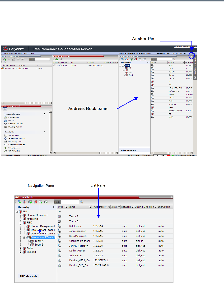
Address Book
Polycom®, Inc. 292
Viewing the Address Book
You can view the participants currently defined in the Address Book. The first time the Collaboration Server
Web Client is accessed, the Address Book pane is displayed.
The Address Book contains two panes:
●Navigation pane - Contains the hierarchical tree and All Participants list.
●List pane - Displays the list of all the members of the selected group and sub-groups.
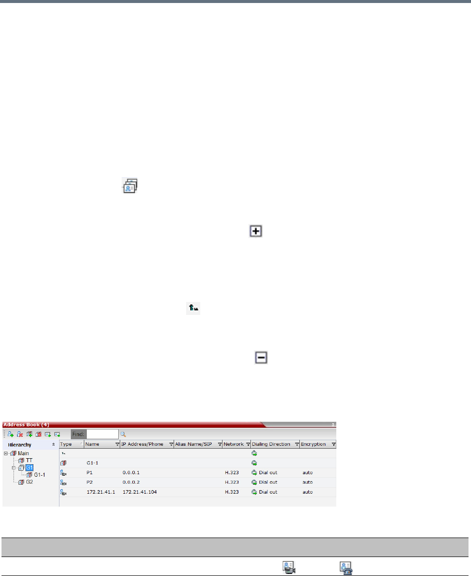
Address Book
Polycom®, Inc. 293
The Navigation pane of the Address Book contains the following types of lists:
●Hierarchical — Displays a multi-level hierarchical tree of groups and participants. Double-clicking a
group on the navigation pane displays the group participants and sub-groups in the List pane.
●All Participants — Double-clicking this selection displays the single unique entity of all the
participants in a single level. When adding a participant to a group, the system adds a link to the
participant’s unique entity that is stored in the All Participants list. The same participant may be added
to many groups at different levels, and all these participant links are associated with the same
definition of the participant in the All Participants list. If the participant properties are changed in one
group, they will be changed in all the groups accordingly.
Displaying and Hiding the Group Members in the Navigation Pane
The currently selected group, whose group members are displayed in the Address Book List pane is
identified by a special icon .
To expand the group to view the group members:
»Double-click the group name or click the Expand button.
The address book entities and sub-groups of the group is displayed in the right group list pane. You
can drill down the sub-group to view address book entities in the sub-group.
To move up to the next level and view the members in the upper level:
»Double-click the navigation arrow button in the group members pane.
To collapse a group:
»Double-click the group name or click the Collapse button.
Participants List Pane Information
The Participants List pane displays the following information for each participant:
Participants List Pane
Field/Option Description
Type Indicates whether the participant is a video ( ) or voice ( ).
Name Displays the name of the participant.
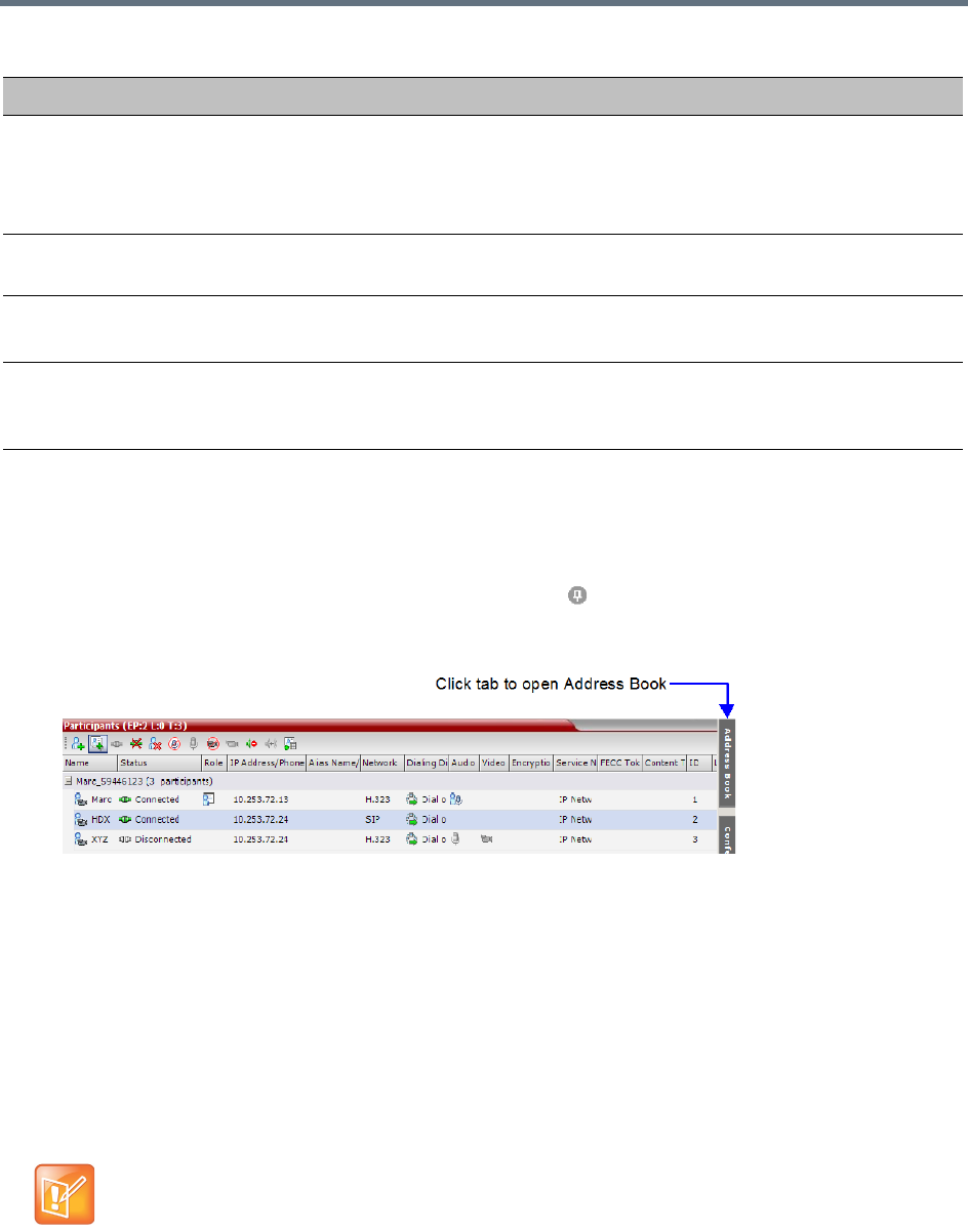
Address Book
Polycom®, Inc. 294
For information on adding and modifying participants in the Address Book, see Managing the Address Book.
Displaying and Hiding the Address Book
The Address Book can be hidden it by clicking the anchor pin ( ) button in the pane header. The Address
Book pane closes and a tab is displayed at the right edge of the screen.
»Click the tab to re-open the Address Book.
Adding Participants from the Address Book
You can add individual participants or a group of participants from the Address Book to a conference.
Adding Individual Participants from the Address Book to Conferences
You can add a participant or multiple participants to a new conference, ongoing conferences, or to
Conference Templates by using the drag-and-drop operation.
In SVC-based conferences, only dial-in participants can be added from the address book.
IP Address/Phone Enter the IP address of the participant’s endpoint.
•For H.323 participant define either the endpoint IP address or alias.
•For SIP participant define either the endpoint IP address or the SIP address.
Note: This field is removed from the dialog box when the ISDN/PSTN protocol is selected.
Network The network communication protocol used by the endpoint to connect to the conference:
H.323 or SIP or ISDN/PSTN.
Dialing Direction Dial-in – The participant dials in to the conference.
Dial-out – The Collaboration Server dials out to the participant.
Encryption Displays whether the endpoint uses encryption for its media.
The default setting is Auto, indicating that the endpoint must connect according to the
conference encryption setting.
Multiple selection of group levels is not available.
Participants List Pane
Field/Option Description
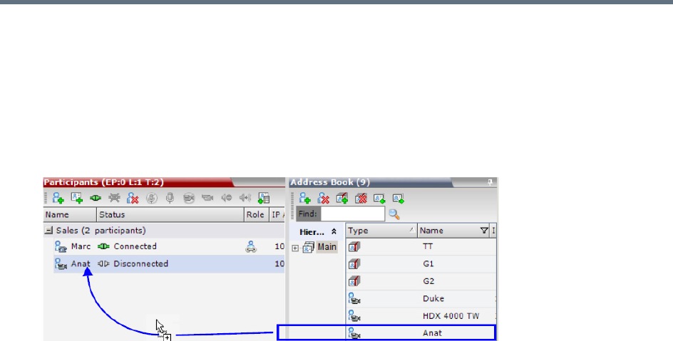
Address Book
Polycom®, Inc. 295
To add a participant to a new conference or an ongoing conference:
1In the Address Book Navigation pane, select the group from which to add participants.
2In the Address Book List pane, select the participant or participants you want to add to the
conference.
3Click and hold the left mouse button and drag the selection to the Participants pane of the
conference.
The participants are added to the conference.
Adding a Group from the Address Book to Conferences
You can add a group of participants to a new conference, ongoing conferences, or to Conference Templates
by using the drag-and-drop operation.
To add a group to a new conference or an ongoing conference:
1In the Address Book Navigation pane, select the group you want to add to the conference.
2Click and hold the left mouse button and drag the selection to the Participants pane of the
conference.
The participants in the group level and all sub-levels are added to the conference.
Participant Groups
A group is a predefined collection of participants. A group provides an easy way to manage clusters of
participants that are in the same organizational structure and to connect a combination of endpoints to a
conference. For example, if you frequently conduct conferences with the marketing department, you can
create a group called “Marketing Team” that contains the endpoints of all members of the marketing team.
Groups can contain participants and sub-groups. You can define up to ten levels in the Main group.
Managing Groups in the Address Book
To manage the groups in the Address Book:
1In the Address Book Navigation pane, right-click the group you want to manage.
The Groups menu is displayed.
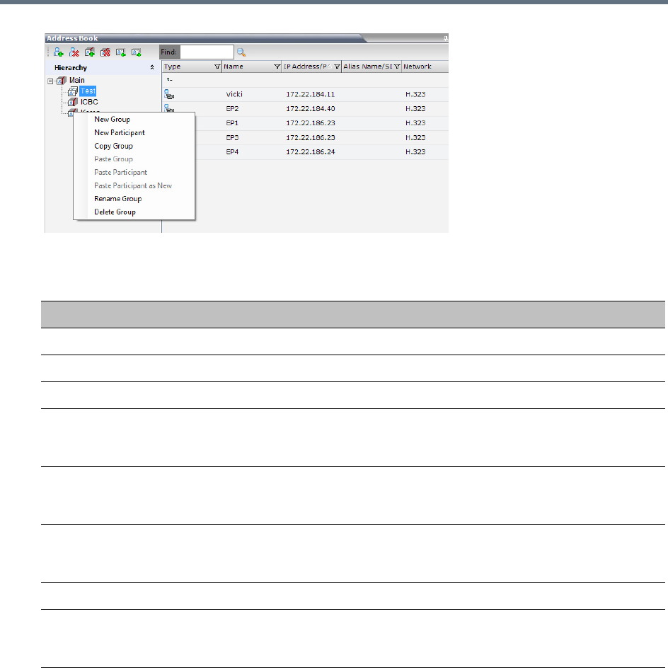
Address Book
Polycom®, Inc. 296
2Select one of the following actions:
:
Additionally, you can drag a group from one location in the Address Book to another location, moving the
group and all its members, including sub-groups, to its new location using the drag-and-drop operation.
Moving a group to a new location can be done in the navigation pane or the list pane.
To drag a group from a location in the address book to another location:
1Select the group you want to move.
2Click and hold the left mouse button and drag the selection to the new location. The new location
can be either the Main root level or another group level.
The group and all its members (participants and groups) are moved to the new address book location.
Address Book Navigation
Action Description
New Group Creates a new group within the current group.
New Participant Adds a new participant within the current group.
Copy Group Copies the current group to be pasted as an additional group.
Paste Group Places the copied group into the current group. The group name of the
copied group is defined with “Copy” at the end of the group name. This
action is only available after a Copy Group action has been implemented.
Paste Participant Places the copied participant into the current selected group. This action
is available after a Copy or Cut action was activated when selecting a
single participant or multiple participants.
Paste Participant as New Pastes as a new participant into the selected group. This paste action
adds “Copy” at the end of the participant name. This action is only
available after a Copy action was activated for a single participant.
Rename Group Renames the group name.
Delete Group Deletes the group and all of its members. This action displays a message
requesting confirmation to delete the group and all members connected
with the group.

Address Book
Polycom®, Inc. 297
Managing the Address Book
Guidelines
●The multi-level Address Book can only be used in a local configuration on the Collaboration Server.
The hierarchical structure cannot be implemented with the Global Address Book (GAB).
●Up to ten levels can be defined in the hierarchical structure of the Address Book.
●The default name of the root level is Main. The Main root level cannot be deleted but the root level
name can be modified.
●Address Book names support multilingual characters.
●Participants in the Address Book can be copied to multiple groups. However, only one participant
exists in the Address Book. Groups that contain the same participants refer to the same definition of
the participant entity.
Adding a Participant to the Address Book
Adding participants to the Address Book can be performed by the following methods:
●Directly in the Address Book.
●Moving or saving a participant from an ongoing conference to the Address Book.
Only defined dial-out ISDN/PSTN participants can be added to the Address Book or ongoing conferences.
ISDN/PSTN participants are added to the Address Book in the same manner that H.323 and SIP
participants are added.
When adding dial-out participants to the ongoing conference, the system automatically dials out to the
participants using the Network Service
(ISDN/PSTN or IP) defined for the connection in the participant
properties.
Adding a New participant to the Address Book Directly
You can add a new participant to the Main group or to a group in the Address Book. Additionally, you can
add a participant from a new conference, ongoing conference, or Conference Template.
To add a new participant to the Address Book:
1In the Address Book - Navigation pane, select the group to where you want to add the new
participant.
2Click the New Participant button ( ) or right-click the group to where you want to add the
participant and select the New Participant option.
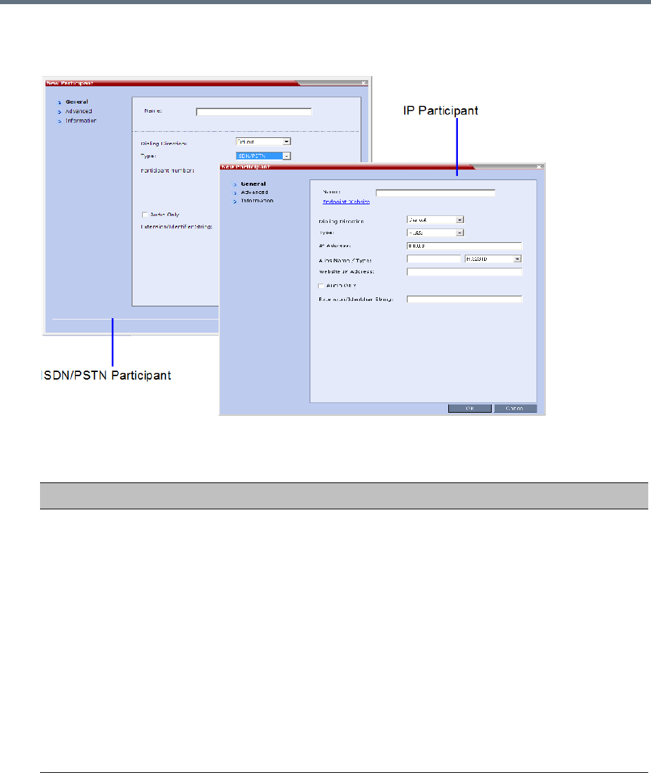
Address Book
Polycom®, Inc. 298
Alternatively, click anywhere in the List pane and select the New Participant option.
The New Participant - General dialog box opens.
3Define the following fields:
New Participant - General
Field Description
Name Enter the name of the participant or the endpoint as it will be displayed in the
Collaboration Server Web Client.
The Name field can be modified using Unicode encoding.
•
English text uses ASCII encoding and can contain the most characters (length
varies according to the field).
•European and Latin text length is approximately half the length of the maximum.
•Asian text length is approximately one third of the length of the maximum.
Maximum field length in ASCII is 80 characters.
The maximum length of text fields varies according to the mixture of character sets
used (Unicode and ASCII).
This field may not be left blank. Duplicate participant names, comma, and semi-colon
characters may not be used in this field.
This name can also become the endpoint name that is displayed in the video layout.
For more details about endpoint (site) names, see Site Names Definition
Note: This field is displayed in all tabs.

Address Book
Polycom®, Inc. 299
Endpoint Website
(IP only)
Click the Endpoint Website hyperlink to connect to the internal website of the
participant’s endpoint. It enables you to perform administrative, configuration and
troubleshooting activities on the endpoint.
The connection is available only if the IP address of the endpoint’s internal site is
defined in the Website IP Address field.
Note: Endpoint Website hyperlinks are not supported when the Collaboration Server
1500/2000/4000 is in Ultra Secure Mode. For more information see Ultra Secure
Mode.
Dialing Direction Select the dialing direction:
• Dial-in – The participant dials in to the conference. This field applies to IP
participants only.
• Dial-out – The MCU dials out to the participant.
Note:
•Dial-out is forced when defining an ISDN/PSTN participant.
Type The network communication protocol used by the endpoint to connect to the
conference: H.323, or SIP or ISDN/PSTN.
The fields in the dialog box change according to the selected network type.
IP Address
(H.323 and SIP)
Enter the IP address of the participant’s endpoint.
•For H.323 participant define either the endpoint IP address or alias.
•For SIP participant define either the endpoint IP address or the SIP address.
For Collaboration Servers registered to a gatekeeper, the Collaboration Server can be
configured to dial and receive calls to and from H.323 endpoints using the IP address
in the event that the Gatekeeper is not functioning.
Note: This field is hidden for ISDN/PSTN participants.
Participant Number
(ISDN/PSTN Only)
Enter the phone number of the ISDN/PSTN participant.
Note: This field is only displayed when the ISDN/PSTN protocol is selected.
Alias Name/Type
(H.323 Only)
If you are using the endpoint’s alias and not the IP address, first select the type of
alias and then enter the endpoint’s alias:
•H.323 ID (alphanumeric ID)
•E.164 (digits 0-9, * and #)
•Email ID (email address format, e.g. abc@example.com)
•Participant Number (digits 0-9, * and #)
Notes:
•Although all types are supported, the type of alias is dependent on the gatekeeper’s
capabilities. The most commonly supported alias types are H.323 ID and E.164.
•This field is used to enter the Entry Queue ID, target Conference ID and
Conference Password when defining a cascaded link.
•Use of the E.164 Number is dependent on the setting of the
REMOVE_IP_IF_NUMBER_EXISTS System Flag. For more information see
Substituting E.164 Number in Dial String.
•This field is removed from the dialog box when the ISDN/PSTN protocol is selected.
New Participant - General
Field Description

Address Book
Polycom®, Inc. 300
SIP Address/Type
(SIP Only)
Select the format in which the SIP address is written:
• SIP URI - Uses the format of an E-mail address, typically containing a user name
and a host name: sip:[user]@[host]. For example, sip:dan@polycom.com.
Note: If the SIP Address field contains an IPv6 address, it must be surrounded by
square brackets, for example, [::1].
• TEL URI - Used when the endpoint does not specify the domain that should
interpret a telephone number that has been input by the user. Rather, each domain
through which the request passes would be given that opportunity.
For example, a user in an airport might log in and send requests through an outbound
proxy in the airport. If the users enters 411 (this is the phone number for local
directory assistance in the United States), this number needs to be interpreted and
processed by the outbound proxy in the airport, and not by the user's home domain.
In this case, tel: 411 is the correct choice.
Note: This field is removed from the dialog box when the ISDN/PSTN protocol is
selected.
Endpoint Website
IP Address
(IP only)
Enter the IP address of the endpoint’s internal site to enable connection to it for
management and configuration purposes.
This field is automatically completed the first time that the endpoint connects to the
Collaboration Server. If the field is blank it can be manually completed by the system
administrator. The field can be modified while the endpoint is connected
Audio Only Select this check box to define the participant as a voice participant, with no video
capabilities.
Extension/Identifier
String
Dial-out participants that connect to an external device such as Cascaded Links or
Recording Links may be required to enter a conference password or an identifying
string to connect. Enter the required string as follows:
[p]…[p][string]
For example: pp4566#
p (optional) - Indicates a pause of one second before sending the DTMF string. Enter
several concatenated [p]s to increase the delay before sending the string. The
required delay depends on the configuration of the external device or conference IVR
system.
String - Enter the required string using the digits 0-9 and the characters * and #. The
maximum number of characters that can be entered is identical to the H.323 alias
length.
If the information required to access the device/conference is composed of several
strings, for example, the conference ID and the conference password, this information
can be entered as one string, where pauses [p] are added between the strings for the
required delays, as follows:
[p]…[p][string][p]…[p] [string]...
For example: p23pp*34p4566#
Extension/Identifier
String
The Collaboration Server automatically sends this information upon connection to the
destination device/conference. The information is sent by the Collaboration Server as
DTMF code to the destination device/conference, simulating the standard IVR
procedure.
New Participant - General
Field Description
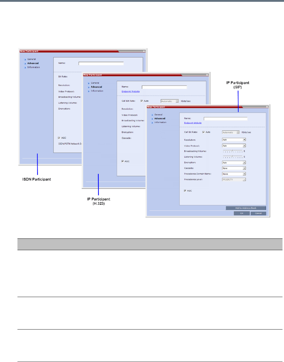
Address Book
Polycom®, Inc. 301
4Usually, additional definitions are not required and you can use the system defaults for the
remaining parameters. In such a case, click OK.
To modify the default settings for advanced parameters, click the Advanced tab.
5Define the following Advanced parameters:
New Participant - Advanced
Field Description
Video Bit Rate / Auto
(IP Only)
The Auto check box is automatically selected to use the Line Rate defined for
the conference.
Note: This check box cannot be cleared when defining a new participant during
an ongoing conference.
To specify the video rate for the endpoint, clear this check box, and then select
the required video rate.
Video Protocol Select the video compression standard that will be forced by the MCU on the
endpoint when connecting to the conference: H.261, H.263, H.264 or RTV.
Select Auto to let the MCU select the video protocol according to the endpoint’s
capabilities.
Resolution The Auto check box is automatically selected to use the Resolution defined for
the conference.
To specify the Resolution for the participant, select the required resolution from
the drop-down menu.

Address Book
Polycom®, Inc. 302
6To add general information about the participant, such as e-mail, company name, and so on, click
the Information tab and type the necessary details in the Info 1-4 fields. Text in the info fields can
be added in Unicode format (length: 31 characters).
7Click OK.
The new participant is added to the selected group in the address book.
Broadcasting Volume +
Listening Volume
To adjust the volume the participant broadcasts to the conference or the volume
the participant hears the conference, move the slider; each unit represents an
increase or decrease of 3 dB (decibel). The volume scale is from 1 to 10, where
1 is the weakest and 10 is the strongest. The default connection value is 5.
Encryption Select whether the endpoint uses encryption for its connection to the
conference.
Auto (default setting) indicates that the endpoint will connect according to the
conference encryption setting.
AGC AGC (Auto Gain Control) mechanism regulates noise and audio volume by
keeping the received audio signals of all participants balanced. Select this check
box to enable the AGC mechanism for participants with weaker audio signals.
Notes:
•To be enable AGC, set the value of the ENABLE_AGC System Flag in
system.cfg to YES. The flag’s default value is NO.
•If the System Flag does not exist in the system, it must be manually added to
the System Configuration. For more information see Modifying System Flags.
•Enabling AGC may result in amplification of background noise.
Cascaded (IP Only) If this participant is used as a link between conferences select:
•Slave, if the participant is defined in a conference running on a Slave MCU.
•Master, if the participant is defined in a conference running on the Master
MCU.
It enables the connection of one conference directly to another conference using
an H.323 connection only. The conferences can run on the same MCU or
different MCU’s. For more information, see Basic Cascading Using IP Cascaded
Link.
Precedence Domain
Name
(Dial-out SIP Only)
When Multi Level Precedence and Preemption is used, this is the Precedence
Domain Name for the participant.
For more information see MLPP (Multi Level Precedence and Preemption).
Precedence Level
(Dial-out SIP Only)
When Multi Level Precedence and Preemption is used, this is the Precedence
Level for the participant
For more information see MLPP (Multi Level Precedence and Preemption).
AGC The Audio Gain Control (AGC) protocol that reduces noises is enabled by
default for the participants.
Clear this check box to disable the AGC feature.
ISDN/PSTN Network
Service
Enables you to select the ISDN/PSTN network service.
New Participant - Advanced
Field Description

Address Book
Polycom®, Inc. 303
Substituting E.164 Number in Dial String
Between the time a conference is scheduled and when it becomes active, the IP of an endpoint may change,
especially in an environment that uses DHCP. The MCU can be set to ignore the IP address of a participant
when the conference starts. Instead, the alternative E.164 number will be used.
The flag, REMOVE_IP_IF_NUMBER_EXISTS controls this option. This flag must be manually added to
change its value. The values of this flag are:
●YES (default) - The IP address of an endpoint will be ignored if an E.164 number (or other) exists.
●NO - The IP address of an endpoint will be used.
Guidelines for Substituting E.164 Number in Dial String
●When this feature is enabled, the IP address field of participants in scheduled conferences and
conference templates will be empty.
●In order for the MCU to ignore the IP of H.323 participants, the following requirements must be met:
A gatekeeper must be defined.
The alias of the participant must be defined.
The alias type must be defined (not set to None).
●If an H.323 gatekeeper is defined but is not connected, the MCU will fail to connect to H.323 dial-out
participants.
●In order for the MCU to ignore the IP of SIP participants, the following requirements must be met:
A SIP proxy must be defined.
The SIP address must be defined.
●If a SIP proxy is defined but is not connected, the MCU will fail to connect to SIP dial-out participants.
Adding a Participant from an Ongoing Conference to the Address
Book
You can add a participant to the Address Book directly from an ongoing conference.
To add a participant from the conference to the Address Book:
1During an ongoing conference, select the participant in the Participant pane, and either click the
Add Participant to Address Book button ( ), or right-click and select Add Participant to
Address Book.
The participant is added to the Address Book.
Alternatively, you could:
aDouble-click the participant’s icon, or right-click the participant icon and select Participant
Properties.
When adding a participant to the address book from a new conference, Participants list of an
ongoing conference or Conference Template, the participant is always added to the “Main” group.
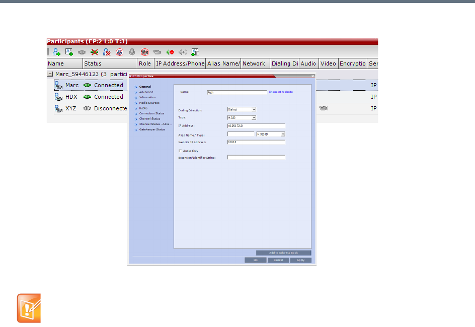
Address Book
Polycom®, Inc. 304
The Participant Properties window opens.
bClick the Add to Address Book button.
Modifying Participants in the Address Book
When required, you can modify the participant’s properties.
To modify participant properties in the Address Book:
1In the Address Book - Navigation pane, select the group to where the participant to modify is
listed.
If the participant name is already listed in the All Participants list, an error message is displayed. In
such a case, change the name of the participant before adding the participant to the address book.
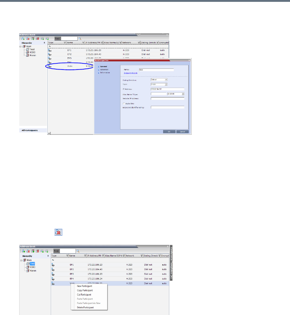
Address Book
Polycom®, Inc. 305
2In the Address Book - List pane, double-click the participant’s icon.
The Participant’s Properties window is displayed.
3Modify the necessary properties in the window, such as dialing direction, communication protocol
type, and so on. You can modify any property in any of the three tabs: General, Advanced and Info.
4Click OK.
The changes to the participant’s properties are updated.
Deleting Participants from the Address Book
To delete participants from the Address Book:
1In the Address Book - Navigation pane, select the group where the participant to delete is listed.
2In the Address Book - List pane, either select the participant to delete, and then select the Delete
Participant ( ) button, or right-click the participant icon and then select the Delete Participant
option.
3A confirmation message is displayed depending on the participant’s assignment to groups in the
address book:
aWhen the participant belongs to only one group: click Yes to permanently delete the participant
from the address book.
bWhen the participant belongs to multiple groups, a message is displayed requesting whether to
delete the participant from the Address Book or from the current selected group. Select:
Current group to delete the participant from the selected group
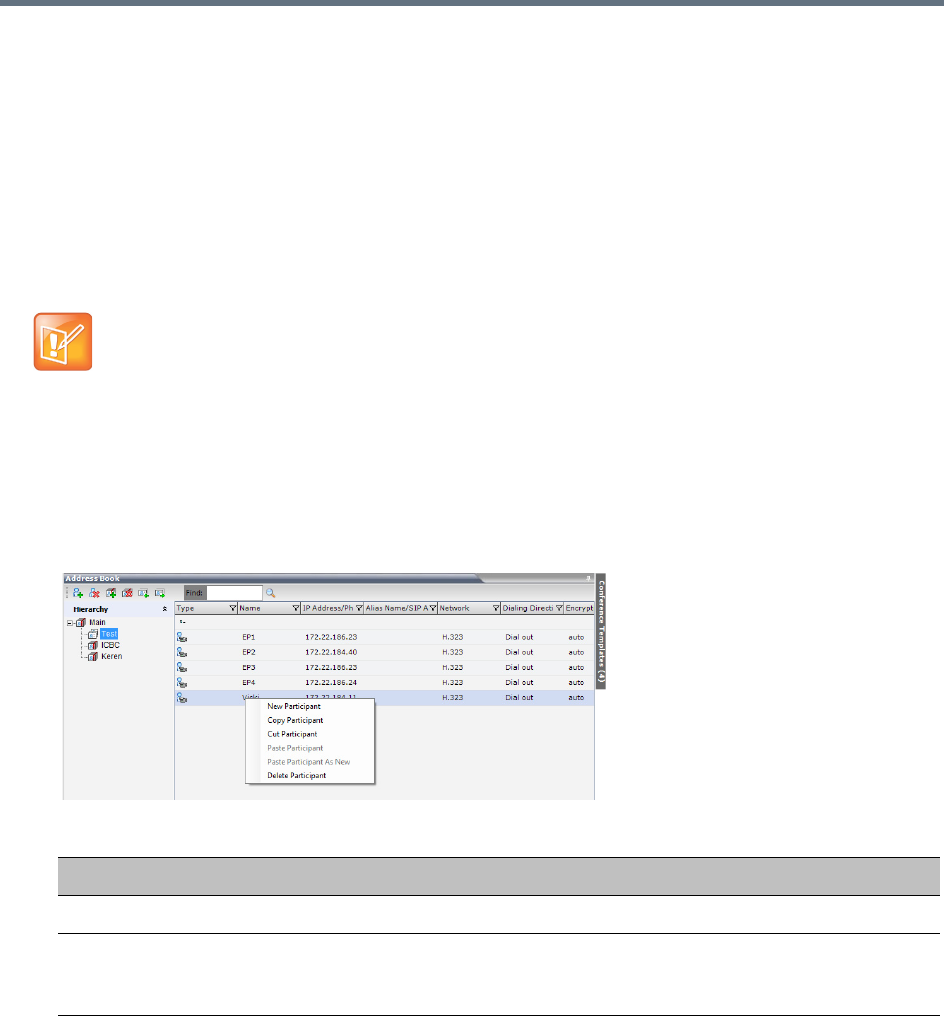
Address Book
Polycom®, Inc. 306
Address Book to permanently delete the participant from the address book (all groups).
Click OK to perform the delete operation, or Cancel to exit the delete operation.
Copying or Moving a Participant
You can copy or move a participant from one group to another group using the Copy, Cut, and Paste options.
A participant can belong to multiple groups. However, there is only one entity per participant. Groups that
contain the same participants refer to the same definition of the participant entity. Alternatively, you can drag
a participant from one location in the Address Book to another location, moving the participant to its new
location using the drag-and-drop operation.
To copy or move a participant to another group:
1In the Address Book - Navigation pane, select the group from where to copy the participant.
2In the Address Book - List pane, select the participant you want to copy.
3Right-click the selected participant, and select one of the following functions from the drop-down
menu:
4In the Address Book - Navigation pane, navigate and select the group in which you want to paste
the participant.
5Right-click the selected group, and click one of the following Paste functions from the drop-down
menu:
The cut and copy actions are not available when selecting multiple participants.
Copy / Move Participant
Function Description
Copy Participant Copies the participant to be pasted into an additional group.
Cut Participant Moves the participant from the current group to a different group. Alternatively,
you can move a participant to another location by dragging the participant to the
new location.
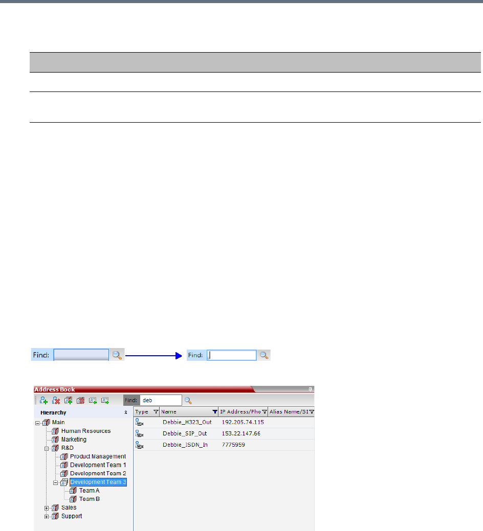
Address Book
Polycom®, Inc. 307
To drag a participant from an address book group to another group:
1Select the participant or participants you want to move.
2Click and hold the left mouse button and drag the selection to the new group.
The participants are moved to the new address book group.
Searching the Address Book
You can search the Address Book for a participant’s name or a group name only on the currently selected
group/level.
To search for participants or groups in the current selected level:
1In the Address Book - Navigation pane, select the group/level within to run the search.
2In the Address Book toolbar, activate the search option by clicking the Find field.
The field clears and a cursor appears indicating that the field is active.
3Type all or part of the participant’s name or group name and click the search button.
The closest matching participant entries are displayed and the Active Filter indicator turns on.
Filtering the Address Book
The entries in an address book group can be filtered to display only the entries (participants or groups) that
meet criteria that you specify and hides entries that you do not want displayed. It enables you to select and
work with a subset of Address Book entries.
Paste Participant
Function Description
Paste Participant Creates a link to the participant entity in the pasted location.
Paste Participant as New Pastes as a new participant into the selected group. This paste action adds
“Copy” to the end of the participant name.
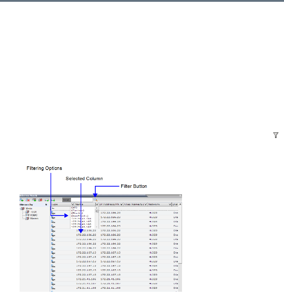
Address Book
Polycom®, Inc. 308
You can filter by more than one column, by adding additional filters (columns).
The filter applies to the displayed group. If All Participants option is selected, it applies to all the listed
participants.
Filtering can be done using:
●A predefined pattern
●Customized pattern
When you use the Find dialog box to search filtered data, only the data that is displayed is searched; data
that is not displayed is not searched. To search all the data, clear all filters.
Filtering Address Book Data Using a Predefined Pattern
To filter the data in an address book group:
1In the Address Book - Navigation pane, select the group to filter.
2In the Address Book - List pane, in the column that you want to use for filtering, click the filter ()
button.
A drop-down menu is displayed containing all the matching patterns that can be applied to the
selected field.
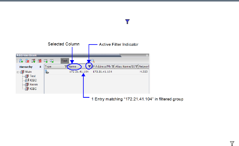
Address Book
Polycom®, Inc. 309
3Click the matching pattern to be applied.
The filtered list is displayed with a filter indicator ( ) displayed in the selected column heading.
Example: If the user selects 172.21.41.104 as the matching pattern, the filtered group in the Address
Book is displayed as follows:
Filtering Address Book Data Using a Custom Pattern
To filter the data in an address book group:
1In the Address Book - Navigation pane, select the group to filter.
2In the Address Book - List pane, in the column that you want to use for filtering, click the filter ()
button.
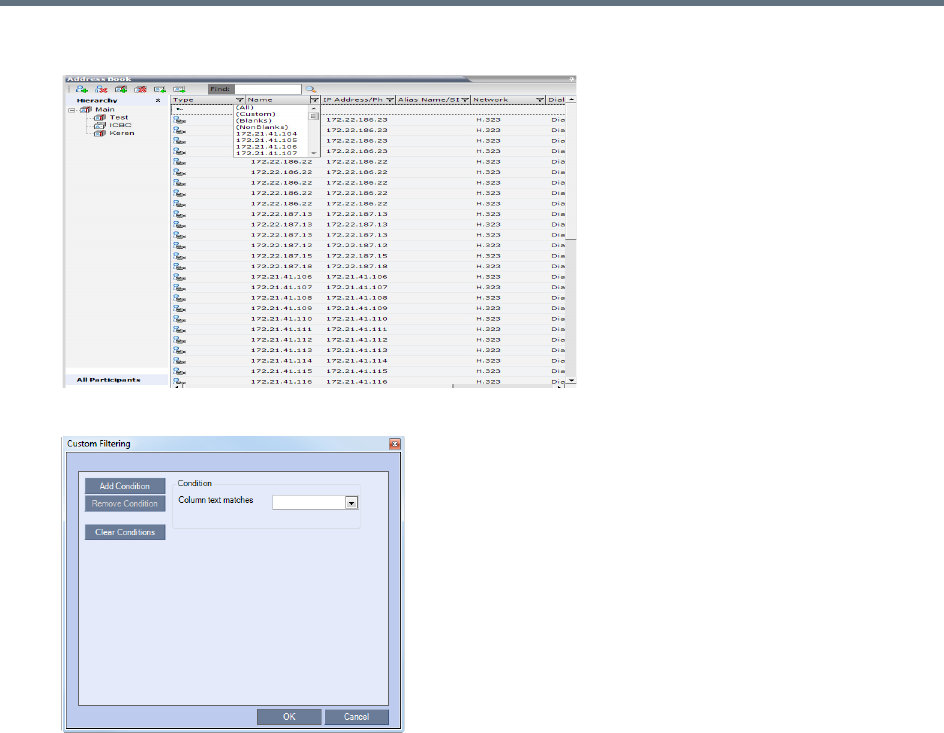
Address Book
Polycom®, Inc. 310
3Select the (Custom) option from the drop-down list.
The Custom Filtering dialog box opens.
4In the Condition - Column text matches field, enter the filtering pattern.
For example, to list only endpoints that include the numerals 41 in their name, enter 41.
5To add filtering patterns to further filter the list or fine tune your search, click Add Condition.
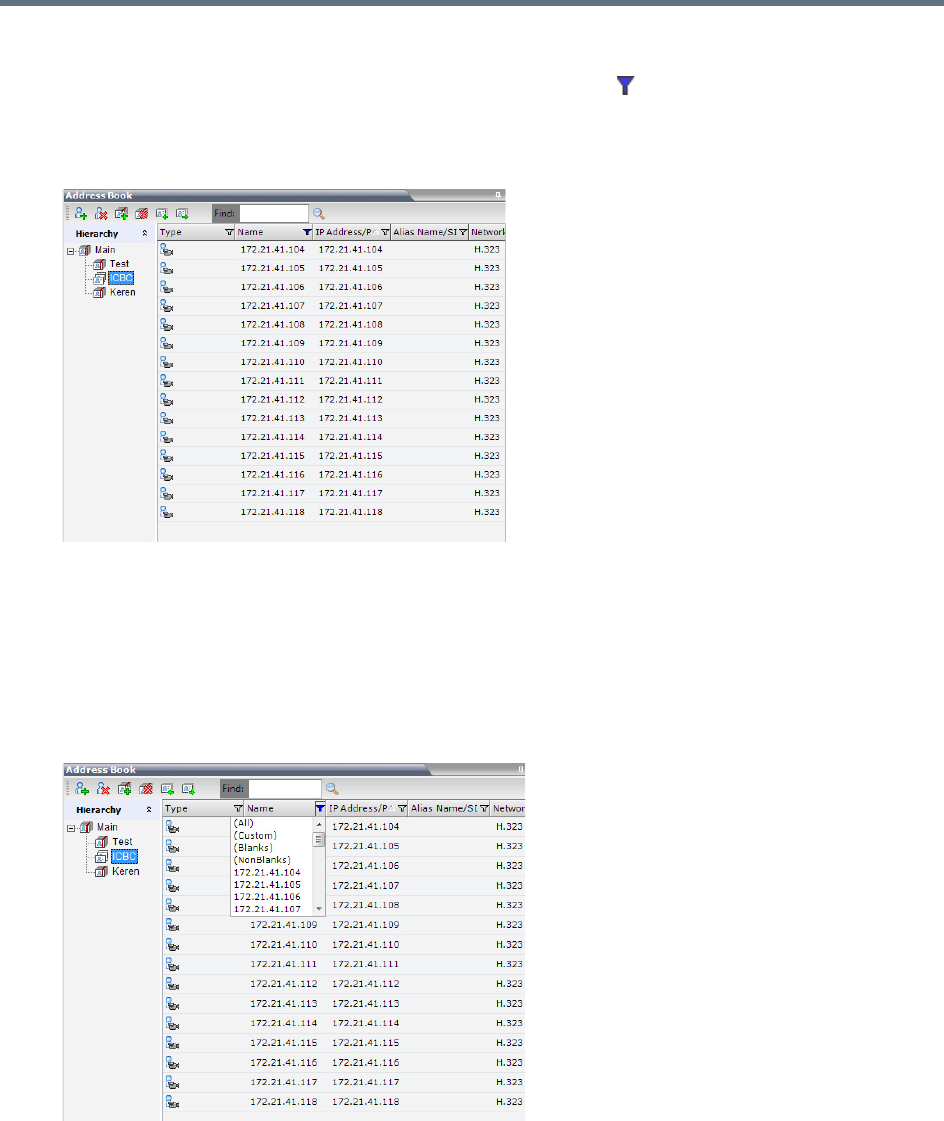
Address Book
Polycom®, Inc. 311
6To clear a filtering pattern, click Clear Condition.
The filtered list is displayed with an active filter (blue) indicator ( ) displayed in the selected column
heading.
For example, if the filtering pattern is 41, the participants list includes all the endpoints that contain
the numerals 41 in their name.
Clearing the Filter
To clear the filter and display all entries:
1In the filtered Address Book column heading, click the Active Filter indicator.
The pattern matching options menu is displayed.
2Click (All).
The filter is deactivated and all the group/level entries are displayed.
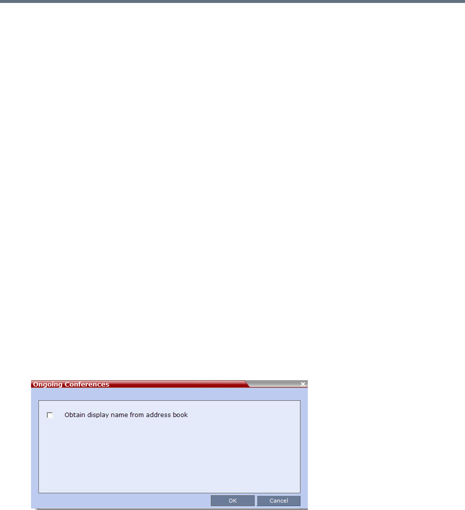
Address Book
Polycom®, Inc. 312
Obtaining the Display Name from the Address Book
The MCU can be configured to replace the name of the dial-in participant as defined in the endpoint (site
name) with the name defined in the Address Book.
In this process, the system retrieves the data (name, alias, number or IP address) of the dial-in participant
and compares it first with the conference defined dial-in participants and if the endpoint is not found, it then
searches for the endpoint with entries in the address book. After a match is found, the system displays the
participant name as defined in the address book instead of the site name, in both the video layout and the
Collaboration Server Web Client/Manager.
The system compares the following endpoint data with the address book entries:
●For H.323 participants, the system compares the IP address, Alias, or H.323 number.
●For SIP participants, the system compares the IP address or the SIP URI.
Guidelines for Obtaining the Display Name from the Address Book
●Only Users with Administrator and Operator Authorization Levels are allowed to enable and disable
the Obtain Display Name from Address Book feature.
●This feature is supported for IPv4 participants only.
Enabling and Disabling the Obtain Display Name from Address Book Feature
The Obtain Display Name from Address Book option can be enabled for all participants connecting to the
MCU if the name of the participants are defined in the Address Book.
To enable or disable the Obtain Display Name from Address Book option:
1On the Collaboration Server main menu bar, select Setup > Customize Display Settings >
Ongoing Conferences.
The Ongoing Conferences dialog box is displayed.
2Select the Obtain display name from address book check box to enable the feature or clear the
check box to disable the feature.
3Click OK.
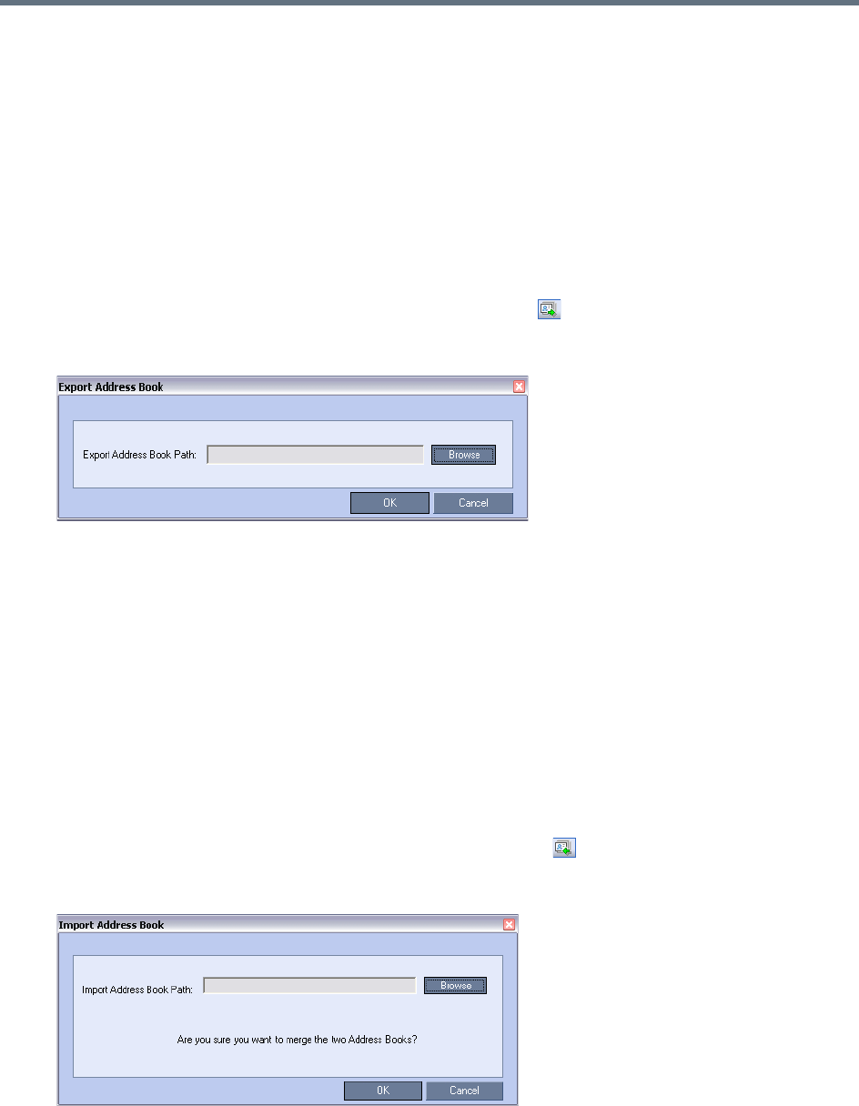
Address Book
Polycom®, Inc. 313
Importing and Exporting Address Books
Address Books are proprietary Polycom data files that can only be distributed among Collaboration Server
units. The Address Books are exported in XML format, which are editable offline. If no name is assigned to
the exported Address Book, the default file name is:
EMA.DataObjects.OfflineTemplates.AddressbookContent_.xml
Exporting an Address Book
To Export an Address Book:
1In the Address Book pane, click the Export Address Book ( ) button, or right-click an empty area
in the pane, and click Export Address Book.
The Export Address Book dialog box is displayed.
2Enter the desired path, or click the Browse button.
3In the Save Address Book dialog box, select the directory to save the file. You may also rename
the file in the File Name field.
4Click Save.
You will return to the Export File dialog box.
5Click OK.
The exported Address Book is saved in the selected folder in XML format.
Importing an Address Book
To Import and Address Book:
1In the Address Book pane, click the Import Address Book ( ) button, or right-click an empty
area in the pane, and then click Import Address Book.
The Import Address Book dialog box is displayed.
2Enter the path from which to import the Address Book, or click the Browse button.

Address Book
Polycom®, Inc. 314
3In the Open dialog box navigate to the desired Address Book file (in XML format) to import.
4Click Open.
You will return to the Import File dialog box.
5Click OK.
The Address Book is imported and a confirmation message is displayed at the end of the process.
6Click Close.
Upgrading and Downgrading Considerations
When upgrading to a multi-level address book version from a single-level address book, the following
factors have to be taken into consideration:
●The system automatically creates a new address book with a different name and modifies the new
address book to a multi-level hierarchical address book.
●By default, the address book contains two levels:
The top level (root) named Main.
Second level - All address book groups from the single-level address book are placed under the
Main group with their associated participants.
●Participants that were not previously associated with any group in the Address Book are placed in the
Main group.
●All participants in the Address Book appear in the All Participants group.
●During the upgrade process, the single-level address book file is save in the system to enable a future
the downgrade of the version to a previous, single-level address book version (if required).
When downgrading from a multi-level address book version to a single-level address book version, the
multi-level address book is replaced during the downgrade process by the single-level address book that
was saved during the upgrade process.
Integrating the Global Address Book (GAB) with the
Collaboration Server
The RealPresence Resource Manager includes a Global Address Book (GAB) with all registered endpoints.
This address book can be used by the RealPresence Collaboration Server users to add participants to
conferences.
Integration with Resource Manager
●The RealPresence Collaboration Server can use only one address book at a time.
When importing an Address Book, participants with exact names in the current Address Book will be
overwritten by participants defined in the imported Address Book.
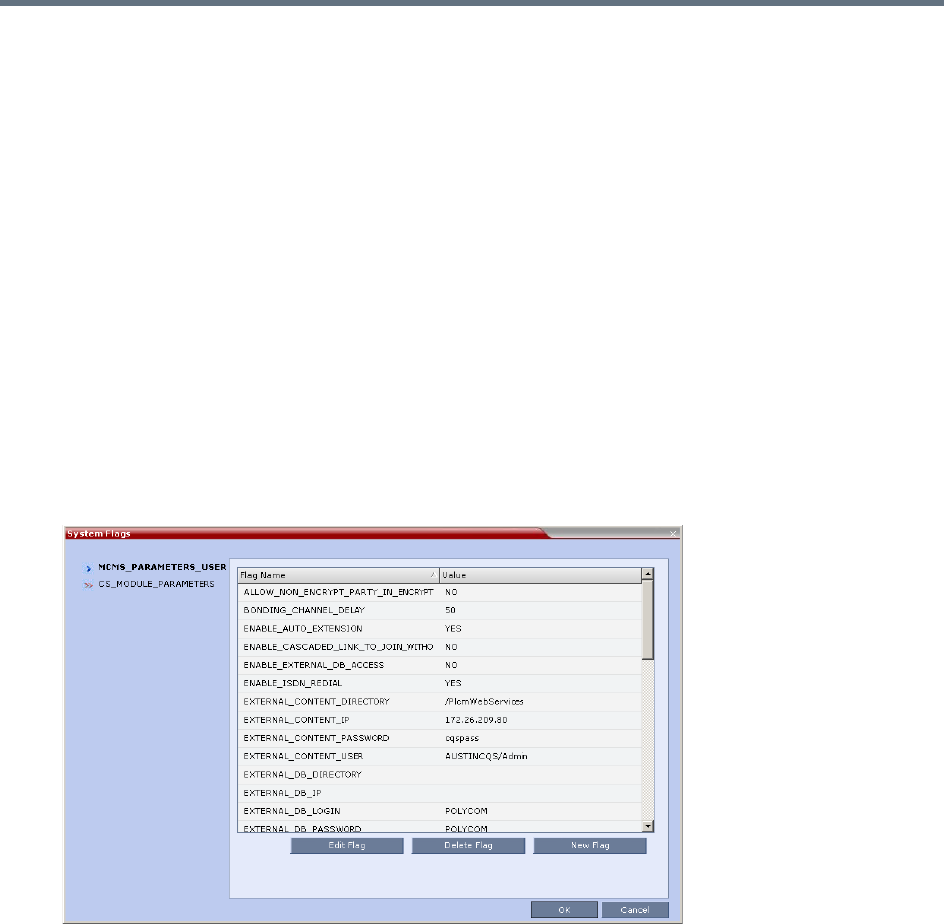
Address Book
Polycom®, Inc. 315
●The Collaboration Server uses the RealPresence Resource Manager address book in read-only
mode. You can only add or modify the address book entries from the RealPresence Resource
Manager.
To Integrate the RealPresence Resource Manager Global Address Book (GAB) with the
Collaboration Server:
1In the RealPresence Resource Manager, manually add the Polycom Collaboration Server system to
the RealPresence Resource Manager as directed in the RealPresence Resource Manager
Operations Guide.
2In the RealPresence Resource Manager, add a user or use an existing user for Collaboration Server
login as directed in the RealPresence Resource Manager Operations Guide.
Write down the User Name and Password as they will be used later to define the Collaboration Server
connection to the RealPresence Resource Manager Address Book.
RealPresence Collaboration Server Side
1On the RealPresence Collaboration Server menu, click Setup > System Configuration.
The System Flags - MCMS_PARAMETERS_USER dialog box opens.
2Modify the values of the flags in the table below.
For more information, see Modifying System Flags.
3Click OK to complete the definitions.
4When prompted, click Yes to reset the MCU and implement the changes to the system
configuration.

Polycom®, Inc. 316
Scheduling Reservations
The Reservations option enables users to schedule conferences. These conferences can be launched
immediately or become ongoing, at a specified time on a specified date.
Scheduling a conference reservation requires definition of conference parameters such as the date and time
at which the conference is to start, the participants and the duration of the conference.
Scheduled conferences (Reservations) can occur once or repeatedly, and the recurrence pattern can vary.
The maximum number of reservations per Collaboration Server is:
●RealPresence Collaboration Server (RMX) 1500/1800/2000 - 2000
●RealPresence Collaboration Server (RMX) 4000 - 4000
●Reservations are not supported by Collaboration Server (RMX) 1800-0.
Guidelines for Scheduling Reservations
System
●By default, the Scheduler is enabled by a System Flag. The flag prevents potential scheduling
conflicts from occurring as a result of system calls from external scheduling applications such as
RealPresence Resource Manager, ReadiManager®, SE200, and others via the API.
If an external scheduling application is used, the flag INTERNAL_SCHEDULER must be manually
added to the System Configuration and its value must be set to NO.
For more information see Modifying System Flags.
Resources
●System resources are calculated according to the Collaboration Server’s license. For more
information, see Forcing Video Resource Allocation to CIF Resolution.
●System resource availability is partially checked when reservations are created:
If a conference duration extension request is received from an ongoing conference, the request
is rejected if it would cause a resource conflict.
If several reservations are scheduled to be activated at the same time and there are not enough
resources for all participants to be connected:
The conferences are activated.
Participants are connected to all the ongoing conferences until all system resources are used
up.
●If sufficient resources are not available in the system and a scheduled Reservation cannot be
activated, the Reservation is deleted from the schedule.
In the RealPresence CloudAxis Solution, Reservations are scheduled in the RealPresence Resource
Manager (XMA) component and should not be scheduled directly in the RealPresence Collaboration
Server (RMX) 1500/1800/2000/4000 component.

Scheduling Reservations
Polycom®, Inc. 317
●In RealPresence Collaboration Server (RMX) 1500/2000/4000, resources for Reservations are also
calculated using the Reserve Resources for Audio/Video Participants fields of the New Reservation
dialog box. For more information see Resources.
●Resources are reserved for participants at the highest video resolution supported by the Line Rate
specified in the conference Profile and up to the maximum system video resolution specified by the
Resolution Configuration dialog box.
●When a new Reservation is created in the Reservation Calendar, the effect of the new Reservation
(including its recurrences) on available resources is checked. If resource deficiencies are found an
error message is displayed.
Defined dial-in or dial-out participants, Meeting Rooms, Entry Queues and new connections to
Ongoing conferences are not included in the resources calculation.
Reservations
●A Reservation that has been activated and becomes an ongoing conference is deleted from the
Reservation Calendar list.
●The maximum number of concurrent reservations is 80. Reservations with durations that overlap (for
any amount of time) are considered to be concurrent.
●System resource availability is partially checked when reservations are created:
If a conference duration extension request is received from an ongoing conference, the request
is rejected if it would cause a resource conflict.
If several reservations are scheduled to be activated at the same time and there are not enough
resources for all participants to be connected:
The conferences are activated.
Participants are connected to all the ongoing conferences until all system resources are used
up.
●A scheduled Reservation cannot be activated and is deleted from the schedule if:
An Ongoing conference has the same Numeric ID.
Sufficient resources are not available in the system.
●If a problem prevents a Reservation from being activated at its schedule time, the Reservation will
not be activated at all. This applies even if the problem is resolved during the Reservation’s
scheduled time slot.
●A Profile that is assigned to a Reservation cannot be deleted.
●Reservations are backed up and restored during Setup > Software Management >Backup /
Restore Configuration operations. For more information see Software Management.
●All existing reservations are erased by the Standard Restore option of the Administration > Tools
> Restore Factory Defaults procedure.
●Reservations can also be scheduled from Conference Templates. For more information see
Scheduling a Reservation From a Conference Template.
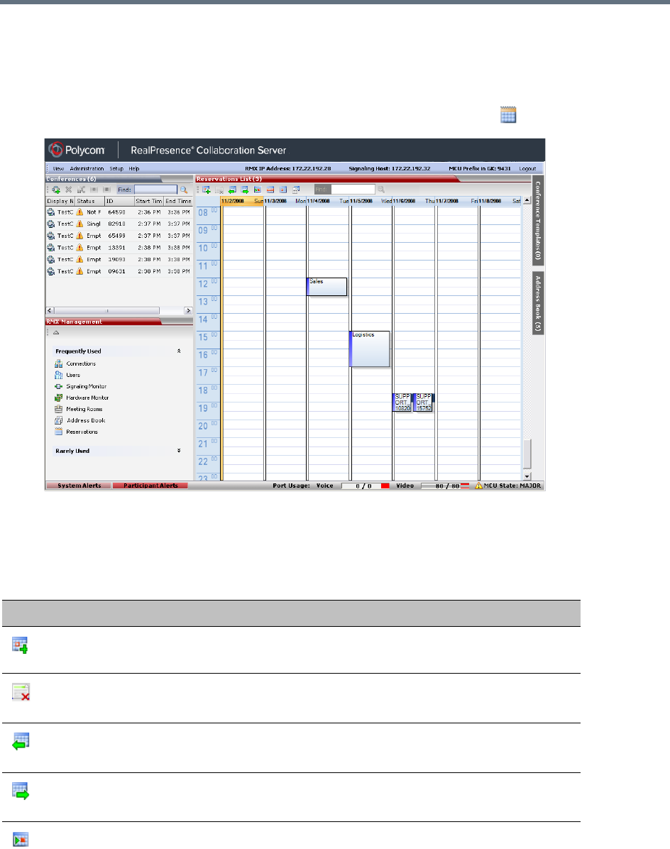
Scheduling Reservations
Polycom®, Inc. 318
Using the Reservation Calendar
To open the Reservation Calendar:
●In the RMX Management pane, click the Reservation Calendar button ( ).
Toolbar Buttons
The toolbar buttons functions are described in the table below.
Reservations – Toolbar Buttons
Button Description
New Reservation
Create a new reservation. The date and time of the new reservation is
set according to the highlighted blocks on the Reservation Calendar.
Delete Reservation
Click to delete the selected reservation.
Back
Click to show the previous day or week, depending on whether Show
Day or Show Week is the selected.
Next
Click to show the next day or week, depending on whether Show Day
or Show Week is the selected.
Today
Click to show the current date in the Reservation Calendar in either
Show Day or Show Week view.
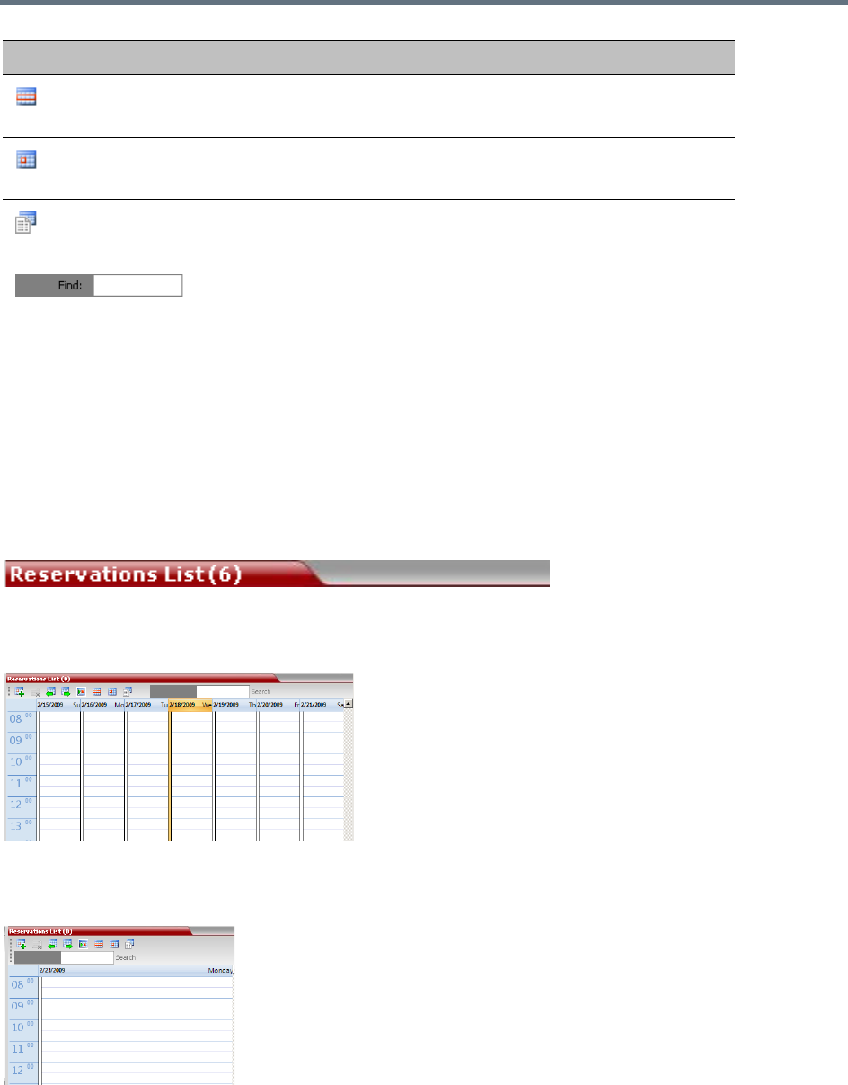
Scheduling Reservations
Polycom®, Inc. 319
Reservations Views
The Reservation Calendar list has the following views available:
●Week
●Day
●Today
●List
In all views the Main Window List Pane header displays the total number of reservations in the system.
Week View
By default the Reservation Calendar is displayed in Week view with the current date highlighted in orange.
Day View
A single day is displayed.
Show Week
Change the calendar view to weekly display, showing a calendar week:
Sunday through Saturday
Show Day
Click this button to show the day containing the selected time slot.
Reservations List
Click to change to List View and display a list of all reservations.
Used to search for reservations by Display Name. (Available in
Reservations List view only).
Button Description
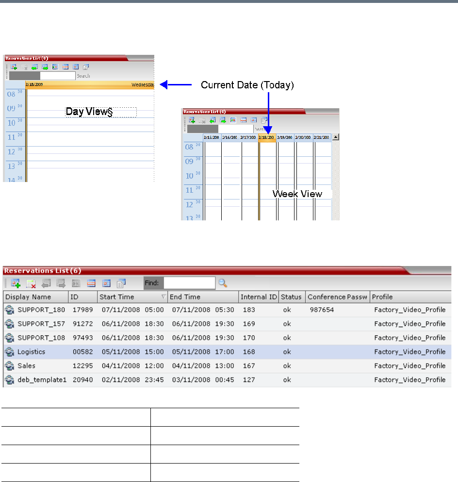
Scheduling Reservations
Polycom®, Inc. 320
Today View
The current date (Today), highlighted in orange, can be viewed in both Week View and Day View.
List View
List View does not have a calendar based format.
All Reservations are listed by:
The Reservations can be sorted, searched and browsed by any of the listed fields.
•Display Name •End Time
•ID •Status
•Internal ID •Conference Password
•Start Time •Profile
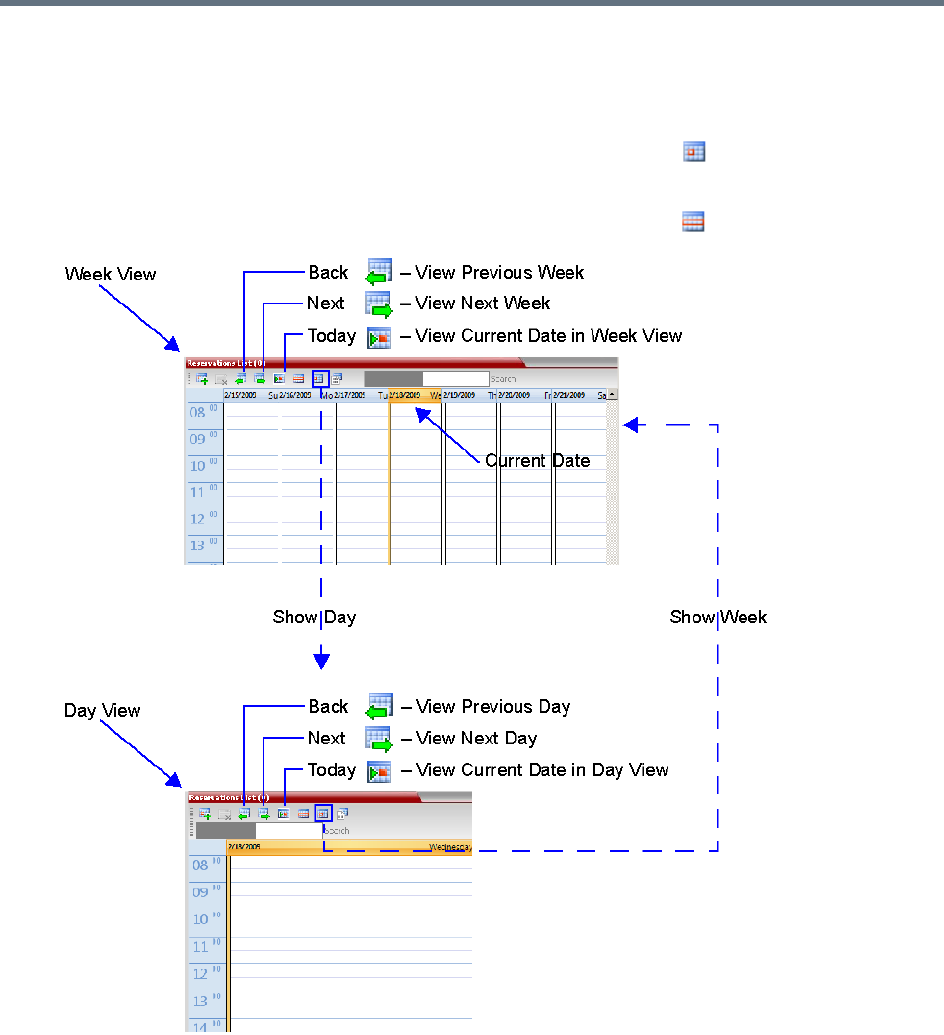
Scheduling Reservations
Polycom®, Inc. 321
Changing the Calendar View
To change between Week and Day views:
1In Week View: In the Reservation Calendar toolbar, click Show Day ( ) to change to Day View.
or
In Day View: In the Reservation Calendar toolbar, click Show Week ( ) to change to Week View.
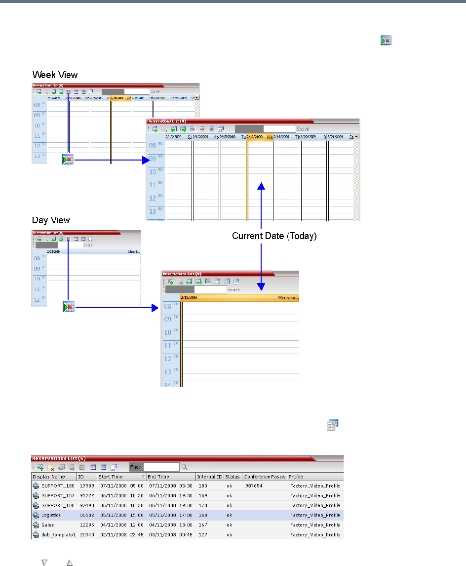
Scheduling Reservations
Polycom®, Inc. 322
To view Today (the current date):
●In Week View or Day View, in the Reservation Calendar toolbar, click the Today ( ) button to have
the current date displayed within the selected view.
To change to List View:
1In the Reservation Calendar toolbar, click, the Reservations List ( ) button.
The Reservations List is displayed.
2To sort the data by any field (column heading), click on the column heading.
A or symbol is displayed in the column heading indicating that the list is sorted by this field, as
well as the sort order.
3To toggle the column’s sort order, click on the column heading.
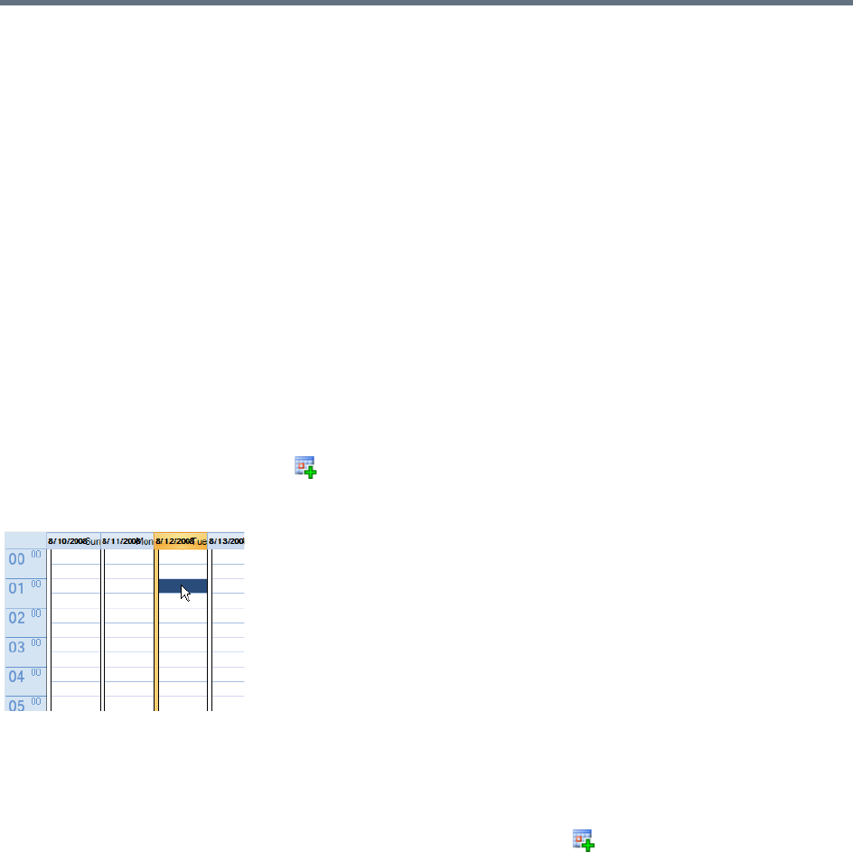
Scheduling Reservations
Polycom®, Inc. 323
To return to Calendar View:
●In the Reservation Calendar toolbar, click any of the buttons (Show Week/Show Day/Today) to
return to the required Reservation Calendar view.
Scheduling Conferences Using the Reservation
Calendar
Creating a New Reservation
There are three methods of creating a new reservation:
●Method I – Creating a reservation with default duration of 1 hour
●Method II – Creating a reservation with default duration of ½ hour
●Method III – Interactively define the reservation duration
Each method requires the selection of a starting time slot in the Reservation Calendar. The default time slot
is the current half-hour period of local time.
In all views, if the New Reservation ( ) button is clicked without selecting a starting time slot, or if a time
slot is selected that is in the past, the Reservation becomes an Ongoing conference immediately and is not
added to the Reservations calendar.
After selecting a starting time slot in the Reservation Calendar you can create a reservation with a default
duration derived from the creation method used or by interactively defining the duration of the reservation.
Method I – To create a reservation with default duration of 1 hour:
»In the Reservation Calendar toolbar, click the New Reservation ( ) button to create a reservation
of 1 hour duration.
Method II – To create a reservation with default duration of ½ hour:
»Right-click and select New Reservation to create a reservation of ½ hour default duration.
Method III – To interactively define the duration:
1In the calendar, click & drag to expand the time slot to select the required Date, Start Time and
Duration for the reservation.
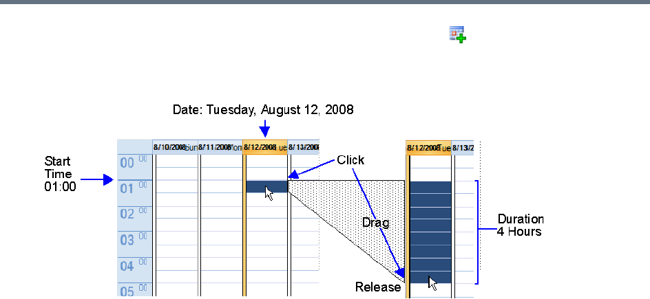
Scheduling Reservations
Polycom®, Inc. 324
2In the Reservation Calendar toolbar, click the New Reservation ( ) button or right-click and
select New Reservation.
Example: The following click & drag sequence would select a reservation for Tuesday, August 12,
2008, starting at 01:00 with a duration of 4 hours.
The duration of reservations created by any of the above methods can be modified in the Scheduler
tab of the New Reservation dialog box.
To create a new reservation:
1Open the Reservation Calendar.
2Select a starting time slot.
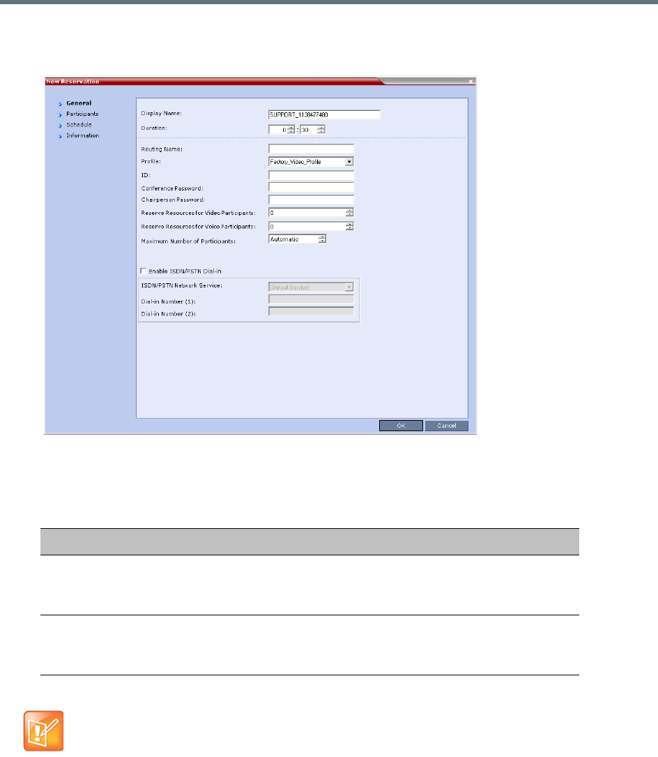
Scheduling Reservations
Polycom®, Inc. 325
3Create the reservation using one of the three methods described above.
The New Reservation – General tab dialog box opens.
All the fields are the same as for the New Conference – General dialog box. For more information,
refer to General Tab.
New Reservation – Reserved Resources
Field Description
Reserve Resources
for Video Participants
Enter the number of video participants for which the system must
reserve resources.
Default: 0 participants.
Reserve Resources
for Audio Participants
Enter the number of audio participants for which the system must
reserve resources.
Default: 0 participants.
When a Conference Profile is assigned to a Meeting Room or a Reservation, the Profile’s parameters
are not embedded in the Reservation, and are taken from the Profile when the reservation becomes an
ongoing conference. Therefore, any changes to the Profile parameters between the time the
Reservation or Meeting Room was created and the time that it is activated (and becomes an ongoing
conference) will be applied to the conference.
If the user wants to save the current parameters, a different Profile with these parameters must be
assigned, or a different Profile with the new parameters must be created.
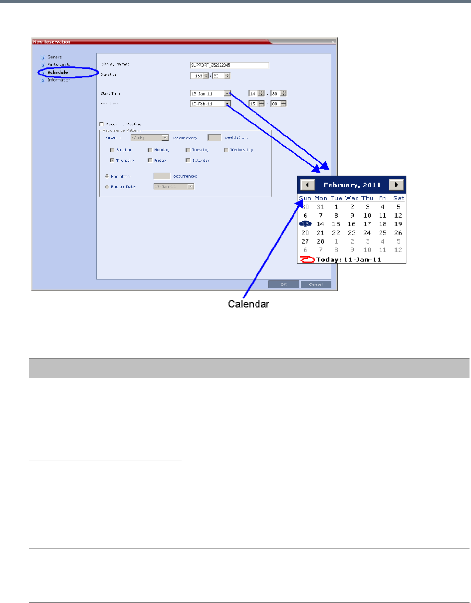
Scheduling Reservations
Polycom®, Inc. 326
4 Click the Schedule tab.
5Adjust the new reservation’s schedule by modifying the fields as described in the table below.
New Reservation – Schedule Tab
Field Description
Start Time Select the Start
Time of the
Reservation.
•The Start/End Times of the Reservation are initially taken from the
time slot selected in the Reservation Calendar.
•The Start/End Times can be adjusted by typing in the hours and
minutes fields or by clicking the arrow buttons.
•The Start/End dates can be adjusted by typing in the date field or
by clicking the arrow buttons or using the calendar.
•The start time of all the reservations can be manually adjusted in
one operation. For more information see Adjusting the Start Times
of all Reservations.
•End Time settings are initially calculated as Start Time + Duration.
End Time settings are recalculated if Start Time settings are
changed.
Changes to End Time settings do not affect Start Time settings.
However, the Duration of the Reservation is recalculated.
End Time Select the End
Time of the
Reservation.
Recurring
Meeting
Select this option to set up a Recurring Reservation - a series of Reservations to be repeated
on a regular basis.
To create a recurring reservation, you must define a time period and a recurrence pattern of
how often the Reservation should occur: Daily, Weekly or Monthly.

Scheduling Reservations
Polycom®, Inc. 327
Recurrence
Pattern
Daily If Daily is selected, the system automatically selects all the days of
the week. To de-select days (for example, weekends) clear their
check boxes.
Weekly If Weekly is selected, the system automatically selects the day of the
week for the Reservation from the day selected in the Reservation
Calendar.
You can also define the recurrence interval in weeks. For example, if
you want the reservation to occur every second week, enter 2 in the
Recur every _ week(s) field.
To define a twice-weekly recurring Reservation, select the check box
of the additional day of the week on which the Reservation is to be
scheduled and set the recurrence interval to 1.
Monthly If Monthly is selected, the system automatically selects the day of the
month as selected in the Reservation Calendar. You are required to
choose a recurrence pattern:
• Day (1-31) of every (1-12) month(s) - Repeats a conference on a
specified day of the month at a specified monthly interval. For
example, if the first Reservation is scheduled for the 6th day of the
current month and the monthly interval is set to 1, the monthly
Reservation will occur on the 6th day of each of the following
months.
• The (first, second,...,last) (Sun-Sat) of x month(s) - Repeats a
Reservation in a particular week, on a specified day of the week at
the specified monthly interval. For example, a recurrent meeting on
the third Monday every second month.
A series of Reservations can be set to end after a specified number of occurrences or by a specific date.
Select one of the following methods of terminating the series of Reservations:
End After End After: x Occurrences - Ends a recurring series of Reservations after a specific number
(x) of occurrences.
Default: 1
(Leaving the field blank defaults to 1 occurrence.)
End by Date End By Date: mm/dd/yyyy - Specifies a date for the last occurrence of the recurring series
of Reservations. The End By Date value can be adjusted by typing in the date field or by
clicking the arrow button and using the calendar utility.
Default: Current date.
New Reservation – Schedule Tab
Field Description
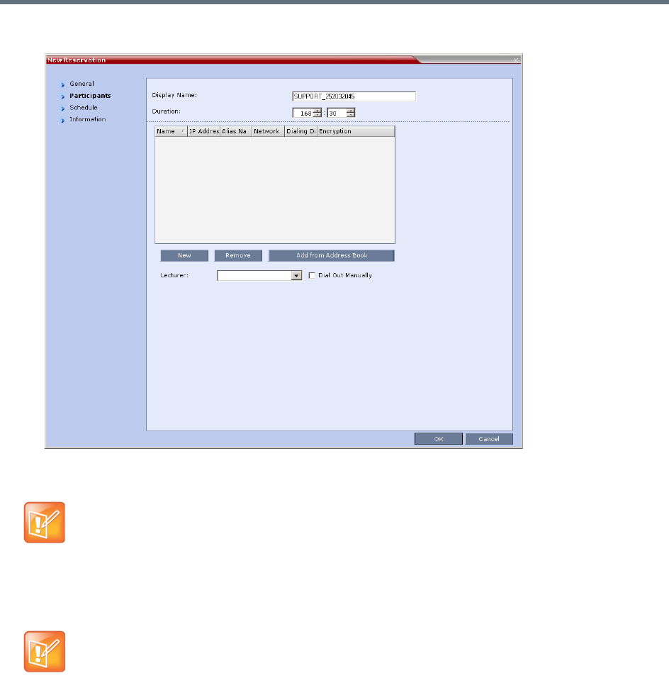
Scheduling Reservations
Polycom®, Inc. 328
6Click the Participants tab.
The fields are the same as for the New Conference – Participants dialog box. For more information,
see Participants Tab.
7You can add participants from the Participants Address Book.
For more information see Adding Participants from the Address Book.
8 Optional. Add information to the reservation.
Information entered in the Information tab is written to the Call Detail Record (CDR) when the
reservation is activated. Changes made to this information before it becomes an ongoing conference
will be saved to the CDR.
For more information see Information Tab.
Participant properties are embedded in the conferencing entity and therefore, if the participant
properties are modified in the Address Book (or Meeting Rooms) after the Reservation has been
created they are not applied to the participant when the Reservation is activated.
Between the time a conference is scheduled and when it becomes active, the IP of an endpoint may
change, especially in an environment that uses DHCP. The MCU can be set to ignore the IP address of
a participant when the conference starts. Instead, the alternative E.164 number will be used instead of
the IP address. For more information see Substituting E.164 Number in Dial String.

Scheduling Reservations
Polycom®, Inc. 329
9Click OK.
The New Reservation is created and is displayed in the Reservation Calendar.
If you create a recurring reservation all occurrences have the same ID. A recurring Reservation is
assigned the same ISDN/PSTN dial-in number for all recurrences.
If a dial in number conflict occurs prior to the conference’s start time, an alert is displayed: ISDN
dial-in number is already assigned to another conferencing entity and the
conference cannot start.
The series number (_0000n) of each reservation is appended to its Display Name.
Example:
Conference Template name: Sales
Display Name for single scheduled occurrence: Sales
If 3 recurrences of the reservation are created:
Display Name for occurrence 1: Sales_00001
Display Name for occurrence 2: Sales_00002
Display Name for occurrence 3: Sales_00003
Managing Reservations
Reservations can be accessed and managed via all the views of the Reservations List.
Guidelines
●The Recurrence Pattern fields in the Schedule tab that are used to create multiple occurrences of
a Reservation are only displayed when the Reservation and its multiple occurrences are initially
created.
●As with single occurrence Reservations, only the Duration, Start Time and End Time parameters of
multiple occurrence reservations can be modified after the Reservation has been created.
●A single occurrence Reservation cannot be modified to become a multiple occurrence reservation.
●Reservations can only be modified one at a time and not as a group.
●If Reservations were created as a recurring series, the system gives the option to delete them
individually, or all as series.
Viewing and Modifying Reservations
Reservations can be viewed and modified by using the Week and Day views of the Reservations Calendar
or by using the Reservation Properties dialog box.
Using the Week and Day views of the Reservations Calendar
In the Week and Day views each Reservation is represented by a shaded square on the Reservation
Calendar. Clicking on a Reservation selects the Reservation. A dark blue border is displayed around the
edges of the Reservation indicating that it has been selected.
The Start Time of the Reservation is represented by the top edge of the square while the End Time is
represented by the bottom edge.
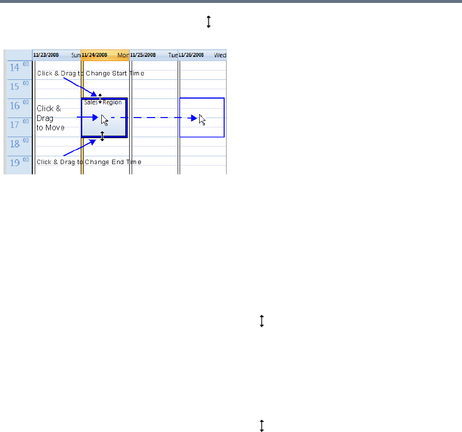
Scheduling Reservations
Polycom®, Inc. 330
The cursor changes to a vertical double arrow ( ) when it is moved over the top and bottom sides of the
square.
To move the Reservation to another time slot:
1Select the Reservation.
2Hold the mouse button down and drag the Reservation to the desired time slot.
3Release the mouse button.
To change the Reservation’s Start time:
1Select the Reservation.
2Move the mouse over the top edge of the Reservation’s square.
3When the cursor changes to a vertical double arrow ( ) hold the mouse button down and drag the
edge to the desired Start Time.
4Release the mouse button.
To change the Reservation’s End time:
1Select the Reservation.
2Move the mouse over the bottom edge of the Reservation’s square.
3When the cursor changes to a vertical double arrow ( ) hold the mouse button down and drag the
edge to the desired End Time.
4Release the mouse button.
To View or Modify Reservations using the Reservation Properties dialog box:
1In the Reservations List, navigate to the reservation (or its recurrences) you want to view, using the
Show Day, Show Week, Today, Back, Next or List buttons.
2Double-click, or right-click and select Reservation Properties, to select the reservation to be
viewed or modified.
The Reservation Properties – General dialog box opens.
3Select the tab(s) of the properties you want to view or modify.
4 Optional. Modify the Reservation Properties.

Scheduling Reservations
Polycom®, Inc. 331
5Click OK.
The dialog box closes and modifications (if any) are saved.
Adjusting the Start Times of all Reservations
When utilizing GMT offset (for example, Daylight Saving Time change), the start time of the reoccurring
reservations scheduled before the Collaboration Server time change are not updated accordingly (although
their start times appear correctly in the Reservations list, when checking the reservation properties the start
time is incorrect).
Following the Collaboration Server time change, the start time of all reoccurring reservations must be
manually adjusted in one operation.
Using this option, the start times of all reservations currently scheduled on the Collaboration Server are
adjusted with the same offset.
To adjust the reoccurring reservations start time after the GMT Offset has been changed
for Daylight Saving Time (DST) or a physical move:.
1On the Collaboration Server menu, click Setup > RMX Time.
The RMX Time dialog box opens.
Adjustment of Reservation Time should only be performed after adjustment of Collaboration Server
Time is completed as a separate procedure.
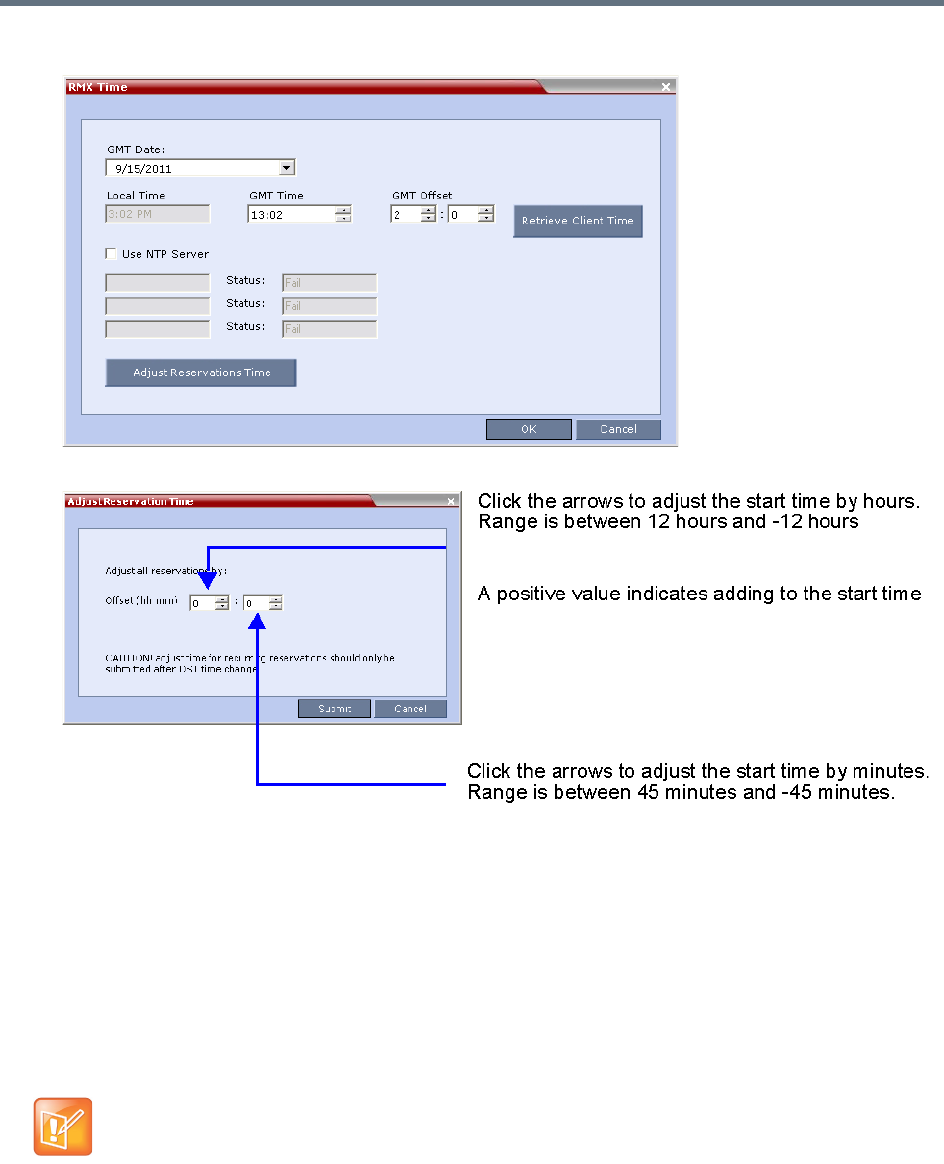
Scheduling Reservations
Polycom®, Inc. 332
2Click the Adjust Reservations Time button.
The Adjust Reservations Time dialog box opens.
3Click the arrows of the Offset - Hours box to indicate the number of hours to add or subtract from
the current start time; a positive value indicates adding time, while minus (-) indicates subtracting
time.
4Click the arrows of the Offset - minutes box to indicate the number of minutes to add or subtract
from the current start time of the reservations. Increments or decrements are by 15 minutes.
For example, to subtract 30 minutes from the start time of all the reservation, enter 0 in the hours
box, and -30 in the minutes box.
To add one hour and 30 minutes to the start time, enter 1 in the hours box and 30 in the minutes box.
5Click the Adjust button to apply the change to all the reoccurring reservations currently scheduled
on the Collaboration Server.
When adjusting the start time of 1000 - 2000 reservations, an Internal communication error
message may appear. Ignore this message as the process completes successfully.
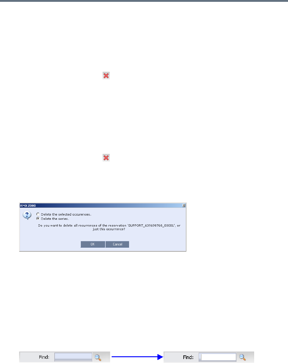
Scheduling Reservations
Polycom®, Inc. 333
Deleting Reservations
To delete a single reservation:
1In the Reservations List, navigate to the reservation you want to delete, using the Show Day, Show
Week, Today, Back, Next or List buttons.
2Click to select the reservation to be deleted.
3Click the Delete Reservation () button.
or
Place the mouse pointer within the Reservation block, right-click and select Delete Reservation.
4Click OK in the confirmation dialog box.
The Reservation is deleted.
To delete all recurrences of a reservation:
1In the Reservations List, navigate to the Reservation or any of its recurrences, using the Show Day,
Show Week, Today, Back, Next or List buttons.
2Click the Delete Reservation () button.
or
Place the mouse pointer within the Reservation or any of its recurrences, right-click and select Delete
Reservation.
A confirmation dialog box is displayed.
3Select Delete the series.
4Click OK.
All occurrences of the Reservation are deleted.
Searching for Reservations using Quick Search
Quick Search is available only in List View. It enables you to search for Reservations by Display Name.
To search for reservations:
1In the Reservation Calendar toolbar, click in the Quick Search field.
The field clears and a cursor is displayed indicating that the field is active.
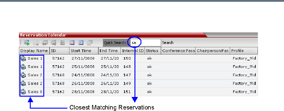
Scheduling Reservations
Polycom®, Inc. 334
2Type all or part of the reservation’s Display Name into the field and click Search.
The closest matching Reservation entries are displayed.
3To view or modify the Reservation:
Double- click the Reservation’s entry in the list to open the Reservations Properties dialog box.
or
Right -click the Reservation’s entry in the list and select a menu option to view, modify or delete the
Reservation.
To clear the search and display all reservations:
1Clear the Quick Search field.
2Click Search.
All Reservations are displayed.

Polycom®, Inc. 335
Operator Assistance & Participant Move
Users (operators) assistance to participants is available when:
●Participants have requested individual help (using *0 DTMF code) during the conference.
●Participants have requested help for the conference (using 00 DTMF code) during the conference.
●Participants have problems connecting to conferences, for example, when they enter the wrong
conference ID or password.
In addition, the user (operator) can join the ongoing conference and assist all conference participants.
Operator assistance is available only when an Operator conference is running on the MCU.
The Operator conference offers additional conference management capabilities to the Collaboration Server
users, enabling them to attend to participants with special requirements and acquire participant details for
billing and statistics. This service is designed usually for large conferences that require the personal touch.
Operator Conferences
An Operator conference is a special conference that enables the Collaboration Server user acting as an
operator to assist participants without disturbing the ongoing conferences and without being heard by other
conference participants. The operator can move a participant from the Entry Queue or ongoing conference
to a private, one-on-one conversation in the Operator conference.
In attended mode, the Collaboration Server user (operator) can perform one of the following actions:
●Participants connected to the Entry Queue who fail to enter the correct destination ID or conference
password can be moved by the user to the Operator conference for assistance.
●After a short conversation, the operator can move the participant from the Operator conference to the
appropriate destination conference (Home conference).
●The operator can connect participants belonging to the same destination conference to their
conference simultaneously by selecting the appropriate participants and moving them to the Home
conference (interactively or using the right-click menu).
●The operator can move one or several participants from an ongoing conference to the Operator
conference for a private conversation.
●The operator can move participants between ongoing Continuous Presence conferences.
In the RealPresence CloudAxis Solution, the Conference Profiles are defined in the RealPresence
DMA system component and should not be defined directly in the RealPresence Collaboration Server
(RMX) 1500/1800/2000/4000 component.
Operator conferences and participant move are supported in AVC CP Conferencing Mode only.

Operator Assistance & Participant Move
Polycom®, Inc. 336
Operator Conference Guidelines
●An Operator conference can only run in Continuous Presence mode.
●Operator conference is defined in the Conference Profile. When enabled in Conference Profile, High
Definition Video Switching option is disabled.
●An Operator conference can only be created by a User with Operator or Administrator Authorization
level.
●Operator conference name is derived from the User Login Name and it cannot be modified.
●Only one Operator conference per User Login Name can be created.
●When created, the Operator conference must include one and only one participant - the Operator
participant.
●Only a defined dial-out participant can be added to an Operator conference as an Operator participant
●Once running, the Collaboration Server user can add new participants or move participants from
other conferences to this conference. The maximum number of participants in an Operator
conference is the same as in standard conferences.
●Special icons are used to indicate an Operator conference in the Ongoing Conferences list and the
operator participant in the Participants list.
●An Operator conference cannot be defined as a Reservation.
●An Operator conference can be saved to a Conference Template. An ongoing Operator conference
can be started from a Conference Template.
●The Operator participant cannot be deleted from the Operator conference or from any other
conference to which she/he was moved to, but it can be disconnected from the conference.
●When deleting or terminating the Operator conference, the operator participant is automatically
disconnected from the MCU, even if participating in a conference other than the Operator conference.
●Participants in Telepresence conferences cannot be moved from their conference, but an operator
can join their conference and help them if assistance is required.
●Moving participants from/to an Operator conference follows the same guidelines as moving
participants between conferences. For move guidelines, see Move Guidelines.
●When a participant is moved from the Entry Queue to the Operator conference, the option to move
back to the source (Home) conference is disabled as the Entry Queue is not considered as a source
conference.
●The conference chairperson cannot be moved to the Operator conference following the individual
help request if the Auto Terminate When Chairperson Exits option is enabled, to prevent the
conference from automatically ending prematurely. In such a case, the assistance request is treated
by the system as a conference assistance request, and the operator can join the conference.
Defining the Components Enabling Operator Assistance
To enable operator assistance for conferences, the following conferencing entities must be adjusted or
created:
●IVR Service (Entry Queue and Conference) in which Operator Assistance options are enabled.
●A Conference Profile with the Operator Conference option enabled.
●An active Operator conference with a connected Operator participant.
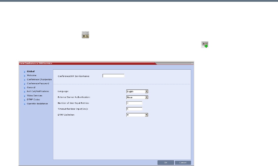
Operator Assistance & Participant Move
Polycom®, Inc. 337
To define a Conference IVR Service with Operator Assistance Options
1In the RMX Management pane, expand the Rarely Used list.
2Click the IVR Services () entry.
3On the IVR Services toolbar, click the New Conference IVR Service () button.
The New Conference IVR Service - Global dialog box opens.
4Enter the Conference IVR Service Name.
5Define the Conference IVR Service - Global parameters. For more information, see Conference
IVR Service Properties - Global Parameters.
6Click the Welcome tab.
The New Conference IVR Service - Welcome dialog box opens.
7Define the system behavior when the participant enters the Conference IVR queue. For more
information, see Defining a New Conference IVR Service.
8Click the Conference Chairperson tab.
The New Conference IVR Service - Conference Chairperson dialog box opens.
9If required, enable the chairperson functionality and select the various voice messages and options
for the chairperson connection. For more information, see New Conference IVR Service Properties -
Conference Chairperson Options and Messages.
10 Click the Conference Password tab.
The New Conference IVR Service - Conference Password dialog box opens.
11 If required, enable the request for conference password before moving the participant from the
conference IVR queue to the conference and set the MCU behavior for password request for Dial-in
and Dial-out participant connections. For more information, see New Conference IVR Service
Properties - Conference Password Parameters.
12 Select the various audio messages that will be played in each case. For more information, see For
more information, see New Conference IVR Service Properties - Conference Password Parameters.
13 Click the General tab.
The New Conference IVR Service - General dialog box opens.
14 Select the messages that will be played during the conference. For more information, see
Conference IVR Service Properties - General Voice Messages.
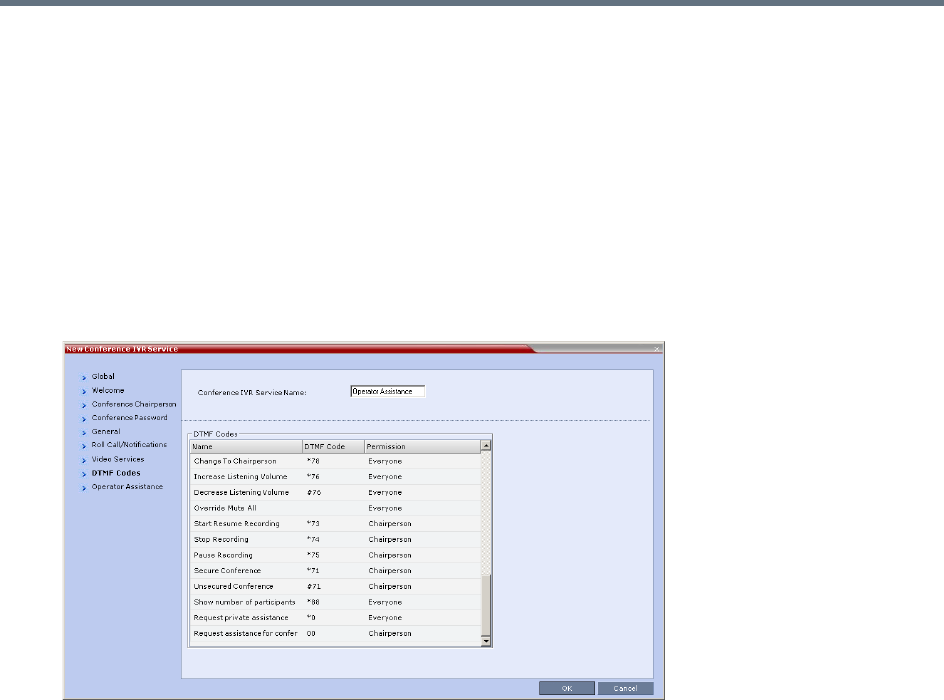
Operator Assistance & Participant Move
Polycom®, Inc. 338
15 Click the Roll Call/Notifications tab.
The New Conference IVR Service - Roll Call dialog box opens.
16 Enable the Roll Call feature and assign the appropriate audio file to each message type. For more
information, see Conference IVR Service Properties - Roll Call Messages.
17 Click the Video Services tab.
The New Conference IVR Service - Video Services dialog box opens.
18 Define the Video Services parameters. For more information, see New Conference IVR Service
Properties - Video Services Parameters.
19 Click the DTMF Codes tab.
The New Conference IVR Service - DTMF Codes dialog box opens.
The default DTMF codes for the various functions that can be performed during the conference by all
participants or by the chairperson are listed. For the full list of the available DTMF codes, see New
Conference IVR Service Properties - DTMF Codes.
20 If required, modify the default DTMF codes and the permissions for various operations including
Operator Assistance options:
*0 for individual help - the participant requested help for himself or herself. In such a case, the
participant requesting help is moved to the Operator conference for one-on-one conversation. By
default, all participants can use this code.
00 for conference help - the conference chairperson (default) can request help for the conference.
In such a case, the operator joins the conference.
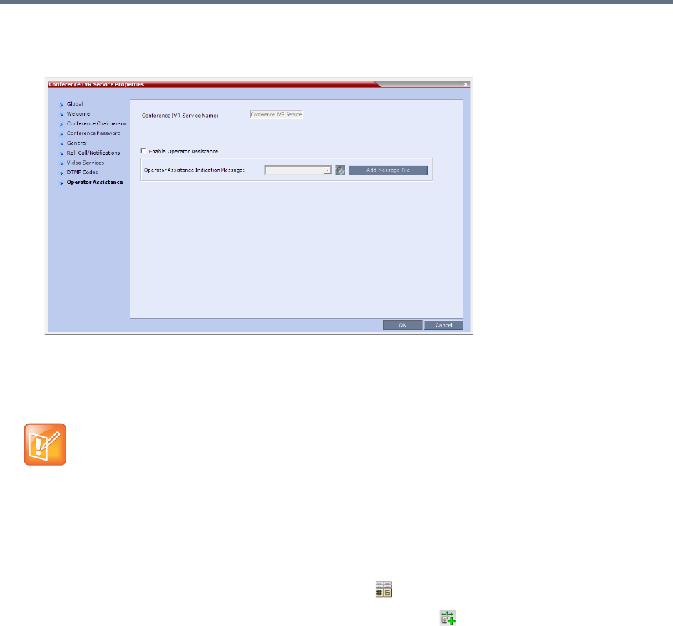
Operator Assistance & Participant Move
Polycom®, Inc. 339
21 Click the Operator Assistance tab.
The Operator Assistance dialog box opens.
22 Select Enable Operator Assistance to enable operator assistance when the participant requires or
requests help during the connection process to the conference or during the conference.
23 In the Operator Assistance Indication Message field, select the audio message to be played
when the participant requests or is waiting for the operator’s assistance.
24 Click OK to complete the IVR Service definition.
The new Conference IVR Service is added to the IVR Services list.
To define an Entry Queue IVR Service with Operator Assistance Options
1In the RMX Management pane, click IVR Services ().
2In the IVR Services list, click New Entry Queue IVR Service ( ).
The New Entry Queue IVR Service - Global dialog box opens.
3Define the Entry Queue Service Name.
4Define the Entry Queue IVR Service Global parameters. For more information, see Entry Queue
IVR Service Properties - Global Parameters.
5Click the Welcome tab.
The New Entry Queue IVR Service - Welcome dialog box opens.
6Define the system behavior when the participant enters the Entry Queue. This dialog box contains
options that are identical to those in the Conference IVR Service - Welcome Message dialog box.
7Click the Conference ID tab.
The New Entry Queue IVR Service - Conference ID dialog box opens.
8Select the required voice messages. For more information, see Entry Queue IVR Service Properties
- Conference ID.
If the audio file was not uploaded prior to the definition of the IVR Service or if you want to add new
audio files, click Add Message File to upload the appropriate audio file to the Collaboration Server.
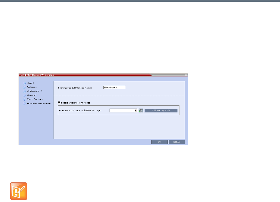
Operator Assistance & Participant Move
Polycom®, Inc. 340
9Click the Video Services tab.
The New Entry Queue IVR Service - Video Services dialog box opens.
10 In the Video Welcome Slide list, select the video slide that will be displayed to participants
connecting to the Entry Queue. The slide list includes the video slides that were previously uploaded
to the MCU memory.
11 Click the Operator Assistance tab.
The Operator Assistance dialog box opens.
12 Select Enable Operator Assistance to enable operator assistance when the participant requires or
requests help during the connection process.
13 In the Operator Assistance Indication Message field, select the audio message to be played
when the participant requests or is waiting for operator’s assistance.
14 Click OK to complete the Entry Queue IVR Service definition.
The new Entry Queue IVR Service is added to the IVR Services list.
To define a Conference Profile for an Operator Conference
1In the RMX Management pane, click Conference Profiles.
2In the Conference Profiles pane, click New Profile.
The New Profile – General dialog box opens.
3Define the Profile name and, if required, the Profile general parameters.
For more details, see New AVC CP Profile - General Parameters.
If the audio file was not uploaded prior to the definition of the IVR Service or if you want to add new
audio files, click Add Message File to upload the appropriate audio file to the Collaboration Server.
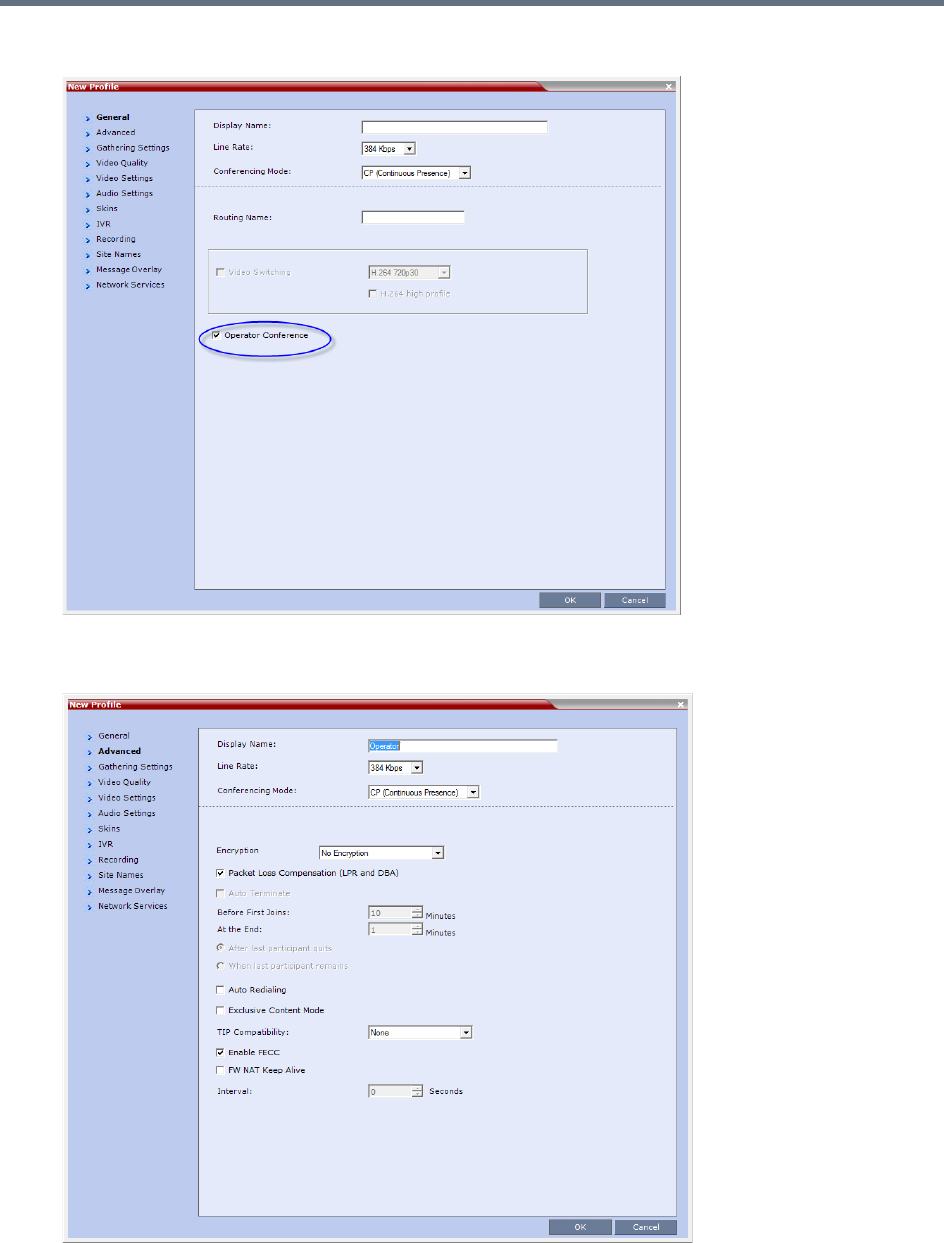
Operator Assistance & Participant Move
Polycom®, Inc. 341
4Click the Operator Conference check box.
5Click the Advanced tab.
The New Profile – Advanced dialog box opens.

Operator Assistance & Participant Move
Polycom®, Inc. 342
6Define the Profile - Advanced parameters. For more details, see New AVC CP Profile - Advanced
Parameters.
Note that when Operator Conference is selected, the Auto Terminate selection is automatically
cleared and disabled and the Operator conference cannot automatically end unless it is terminated
by the Collaboration Server User.
7Click the Video Quality tab.
The New Profile – Video Quality dialog box opens.
8Define the Video Quality parameters. For more details, see New AVC CP Profile - Video Quality
Parameters.
9Click the Video Settings tab.
The New Profile - Video Settings dialog box opens.
10 Define the video display mode and layout. For more details, see New AVC CP Profile - Video
Settings Parameters.
11 Define the remaining Profile parameters. For more details, see Defining AVC CP Conferencing
Profiles.
12 Click OK to complete the Profile definition.
A new Profile is created and added to the Conference Profiles list.
Starting an Ongoing Operator Conference
To start a conference from the Conference pane:
1In the Conferences pane, click New Conference ().
The New Conference – General dialog box opens.
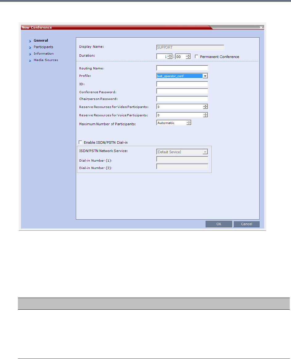
Operator Assistance & Participant Move
Polycom®, Inc. 343
2In the Profile field, select a Profile in which the Operator Conference option is selected.
Upon selection of the Operator Conference Profile, the Display Name is automatically taken from the
Collaboration Server User Login Name. This name cannot be modified.
Only one Operator conference can be created for each User Login name.
3Define the following parameters:
New Conference – General Options
Field Description
Duration Define the duration of the conference in hours using the format HH:MM (default
01:00).
Notes:
•The Operator conference is automatically extended up to a maximum of 168
hours. Therefore, the default duration can be used.
•This field is displayed in all tabs.

Operator Assistance & Participant Move
Polycom®, Inc. 344
Routing Name The name with which ongoing conferences, Meeting Rooms, Entry Queues and
SIP Factories register with various devices on the network such as gatekeepers
and SIP servers. This name must be defined using ASCII characters.
Comma, colon and semicolon characters cannot be used in the Routing Name.
The Routing Name can be defined by the user or automatically generated by the
system if no Routing Name is entered as follows:
•If ASCII characters are entered as the Display Name, it is used also as the
Routing Name
•If a combination of Unicode and ASCII characters (or full Unicode text) is entered
as the Display Name, the ID (such as Conference ID) is used as the Routing
Name.
If the same name is already used by another conference, Meeting Room or Entry
Queue, the Collaboration Server displays an error message and requests that you
to enter a different name.
Profile Select an operator profile from the Profile drop-down list.
ID Enter the unique-per-MCU conference ID. If left blank, the MCU automatically
assigns a number once the conference is launched.
This ID must be communicated to conference participants to enable them to dial in
to the conference.
Conference
Password
Leave this field empty when defining an Operator conference.
Chairperson
Password
Leave this field empty when defining an Operator conference.
Reserve Resources
for Video Participants
Enter the number of video participants for which the system must reserve
resources.
Default: 0 participants.
When defining an Operator conference it is recommended to reserve resources for
at least 2 video participants (for the operator and one additional participant - who
will be moved to the Operator conference for assistance).
Note: This option is not supported with Collaboration Server 1800.
Reserve Resources
for Voice Participants
Enter the number of audio participants for which the system must reserve
resources.
Default: 0 participants.
When defining an Operator conference and the operator is expected to help voice
participants, it is recommended to reserve resources for at least 2 video participants
(for the operator and one additional participant - who will be moved to the Operator
conference for assistance).
Note: This option is not supported with Collaboration Server 1800.
Maximum Number of
Participants
Enter the maximum number of participants that can connect to an Operator
conference (you can have more than two), or leave the default selection
(Automatic).
Maximum number of participants that can connect to an Operator conference:
New Conference – General Options
Field Description

Operator Assistance & Participant Move
Polycom®, Inc. 345
4Click the Participants tab.
The New Conference - Participants dialog box opens.
You must define or add the Operator participant to the Operator conference.
This participant must be defined as a dial-out participant.
Define the parameters of the endpoint that will be used by the Collaboration Server User to connect
to the Operator conference and to other conference to assist participants.
For more information see Participants Tab.
5To insert general information, select the Information tab.
The Information dialog box opens.
6Enter the required information. For more information, see Information Tab.
7Click OK.
The new Operator conference is added to the ongoing Conferences list with a special icon .
The Operator participant is displayed in the Participants list with an Operator participant icon ,
and the system automatically dials out to the Operator participant.
Saving an Operator Conference to a Template
The Operator conference that is ongoing can be saved as a template.
To save an ongoing Operator conference as a template:
1In the Conferences list, select the Operator conference you want to save as a Template.
2Click the Save Conference to Template () button.
or
Right-click and select Save Conference to Template.
Enable ISDN/PSTN
Dial-in
Select this check box if you want ISDN and PSTN participants to be able to connect
directly to the Operator conference. This may be useful if participants are having
problems connecting to their conference and you want to identify the problem or
help them connect to their destination conference.
ISDN/PSTN Network
Service and Dial-in
Number
If you have enable the option for ISDN/PSTN direct dial-in to the Operator
conference, assign the ISDN/PSTN Network Service and a dial-in number to be
used by the participants, or leave these fields blank to let the system select the
default Network Service and assign the dial-in Number.
Note: The dial-in number must be unique and it cannot be used by any other
conferencing entity.
New Conference – General Options
Field Description
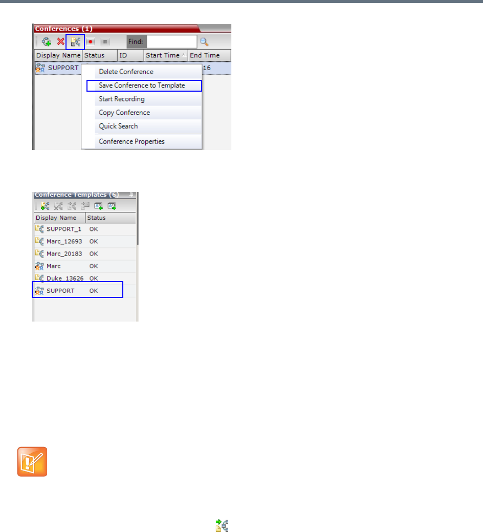
Operator Assistance & Participant Move
Polycom®, Inc. 346
The conference is saved to a template whose name is taken from the ongoing conference Display
Name (the Login name of the Collaboration Server User). The Template is displayed with the
Operator Conference icon.
Starting an Operator Conference from a Template
An ongoing Operator conference can be started from an Operator Template saved in the Conference
Templates list.
To start an ongoing Operator conference from an Operator Template:
1In the Conference Templates list, select the Operator Template to start as an ongoing Operator
conference.
2Click Start Conference from Template ().
or
Right-click and select Start Conference from Template.
•You can only start an Operator conference from a template whose name is identical to your Login
Name. For example, if your Login name is Polycom, you can only start an Operator conference from
a template whose name is Polycom.
•If an ongoing Operator conference with the same name or any other conference with the same ID
is already running, you cannot start another Operator conference with the same login name.
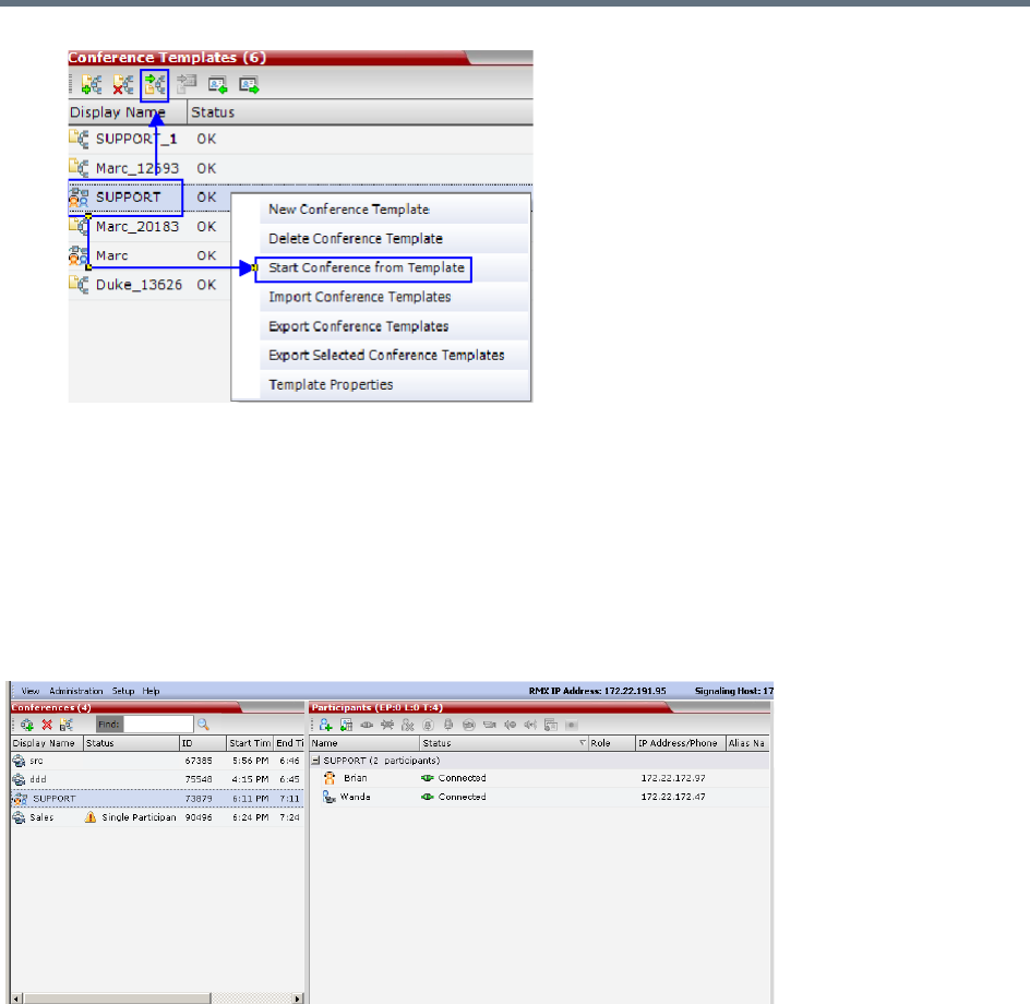
Operator Assistance & Participant Move
Polycom®, Inc. 347
The conference is started.
The name of the ongoing conference in the Conferences list is taken from the Conference Template
Display Name.
Monitoring Operator Conferences and Participants Requiring
Assistance
Operator conferences are monitored in the same way as standard ongoing conferences.
Each Operator conference includes at least one participant - the Operator.
You can view the properties of the Operator conference by double-clicking the conference entry in the
Conferences list or by right-clicking the conference entry and selecting Conference Properties.For more
information, see Participant Level Monitoring.
Requesting Help
A participant can request help using the appropriate DTMF code from his/her touch tone telephone or the
endpoint’s DTMF input device. The participant can request Individual Assistance (default DTMF code *0) or
Conference Assistance (default DTMF code 00).
Participants in Entry Queues who failed to enter the correct destination conference ID or the conference
password will wait for operator assistance (provided that an Operator conference is active).
When requiring or requesting operator assistance, the Collaboration Server management application
displays the following:
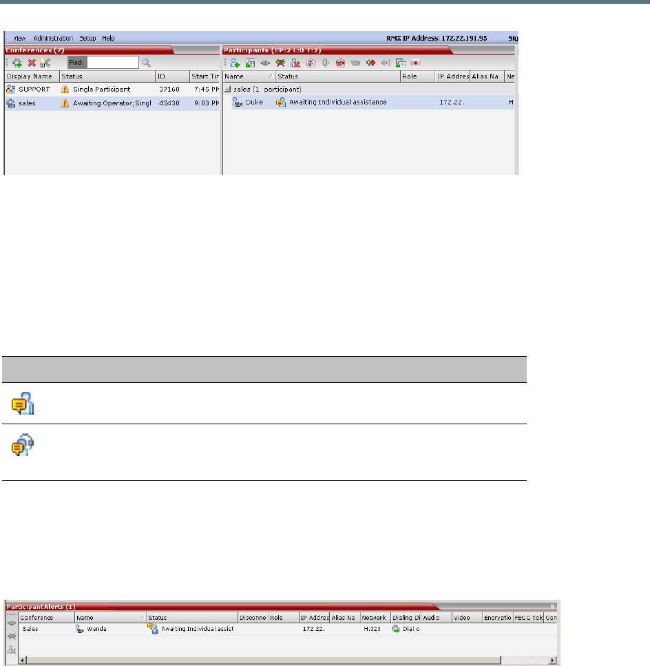
Operator Assistance & Participant Move
Polycom®, Inc. 348
●The participant’s connection Status changes, reflecting the help request. For more information, see
Participants List Status Column Icons and Indications.
●The conference status changes and it is displayed with the exclamation point icon and the status
Awaiting Operator.
●The appropriate voice message is played to the relevant participants indicating that assistance will
be provided shortly.
The following icons and statuses are displayed in the Participant Status column:
When the Operator moves the participant to the Operator conference for individual assistance the
participant Status indications are cleared.
Participant Alerts List
The Participant Alerts list contains all the participants who are currently waiting for operator assistance.
Participants are automatically added to the Participants Alerts list in the following circumstances:
●The participant fails to connect to the conference by entering the wrong conference ID or conference
password and waits for the operator’s assistance
●The participant requests Operator’s Assistance during the ongoing conference
This list is used as reference only. Participants can be assisted and moved to the Operator conference or
the destination conference only from the Participants list of the Entry Queues or ongoing conference where
they are awaiting assistance.
The participants are automatically removed from the Participant Alerts list when moved to any conference
(including the Operator conference).
Participants List Status Column Icons and Indications
Icon Status Indication Description
Awaiting Individual
Assistance
The participant has requested the operator’s
assistance for himself/herself.
Awaiting Conference
Assistance
The participant has requested the operator’s
assistance for the conference. Usually this means
that the operator is requested to join the conference.

Operator Assistance & Participant Move
Polycom®, Inc. 349
Audible Alarms
In addition to the visual cues used to detect events occurring on the Collaboration Server, an audible alarm
can be activated and played when participants request Operator Assistance.
Using Audible Alarms
The Audible Alarm functionality for Operator Assistance requests is enabled for each MCU in either the
Collaboration Server Web Client or RMX Manager.
The Audible Alarm played when Operator Assistance is requested is enabled and selected in the Setup >
Audible Alarm > User Customization. When the Audible Alarm is activated, the *.wav file selected in the
User Customization is played, and it is repeated according to the number of repetitions defined in the User
Customization.
If more than one Collaboration Server is monitored in the RMX Manager, the Audible Alarm must be enabled
separately for each Collaboration Server installed in the site/configuration. A different *.wav file can be
selected for each MCU.
When multiple Audible Alarms are activated in different conferences or by multiple MCUs, the Audible
Alarms are synchronized and played one after the other. It is important to note that when Stop Repeating
Alarm is selected from the toolbar from the Collaboration Server Web Client or RMX Manager, all activated
Audible Alarms are immediately halted.
For more details on Audible alarms and their configuration, see Audible Alarms.

Polycom®, Inc. 350
Conference Templates
Conference Templates enable administrators and operators to create, save, schedule and activate identical
conferences.
A Conference Template:
●Saves the conference Profile.
●Saves all participant parameters including their Personal Layout and Video Forcing settings.
●Simplifies the setting up Telepresence conferences where precise participant layout and video forcing
settings are crucial.
Guidelines
●The maximum number of templates is:
RealPresence Collaboration Server (RMX) 1500/1800/ 2000 - 100
RealPresence Collaboration Server (RMX) 4000 - 200
●A maximum of 200 participants can be saved in a Conference Template.
Trying to start a Conference Template that exceeds the allowed maximum number of participants will
result in participants being disconnected due to resource deficiency.
●If the Profile assigned to a conference is deleted while the conference is ongoing the conference
cannot be saved as a template.
●A Profile assigned to a Conference Template cannot be deleted. The system does not permit such a
deletion.
●Profile parameters are not embedded in the Conference Template, and are taken from the Profile
when the Conference Template becomes an ongoing conference. Therefore, any changes to the
Profile parameters between the time the Conference Template was created and the time that it is
activated (and becomes an ongoing conference) will be applied to the conference.
●Only defined participants can be saved to the Conference Template. Before saving a conference to
a template ensure that all undefined participants have disconnected.
●Undefined participants are not saved in Conference Templates.
●Participant properties are embedded in the Conference Template and therefore, if the participant
properties are modified in the Address Book after the Conference Template has been created they
are not applied to the participant whether the Template becomes an ongoing conference or not.
●The Conference Template display name, routing name or ID can be the same as an Ongoing
Conference, reservation, Meeting Room or Entry Queue as it is not active. However, an ongoing
conference cannot be launched from the Conference Template if an ongoing conference, Meeting
Room or Entry Queue already has the same name or ID. Therefore, it is recommended to modify the
template ID, display name, routing name to be unique.
●A Reservation that has become an ongoing conference can be saved as Conference Template.
●SIP Factories and Entry Queues cannot be saved as Conference Templates.
●The conference specified in the Conference Template can be designated as a Permanent
Conference. For more information see Permanent Conference.
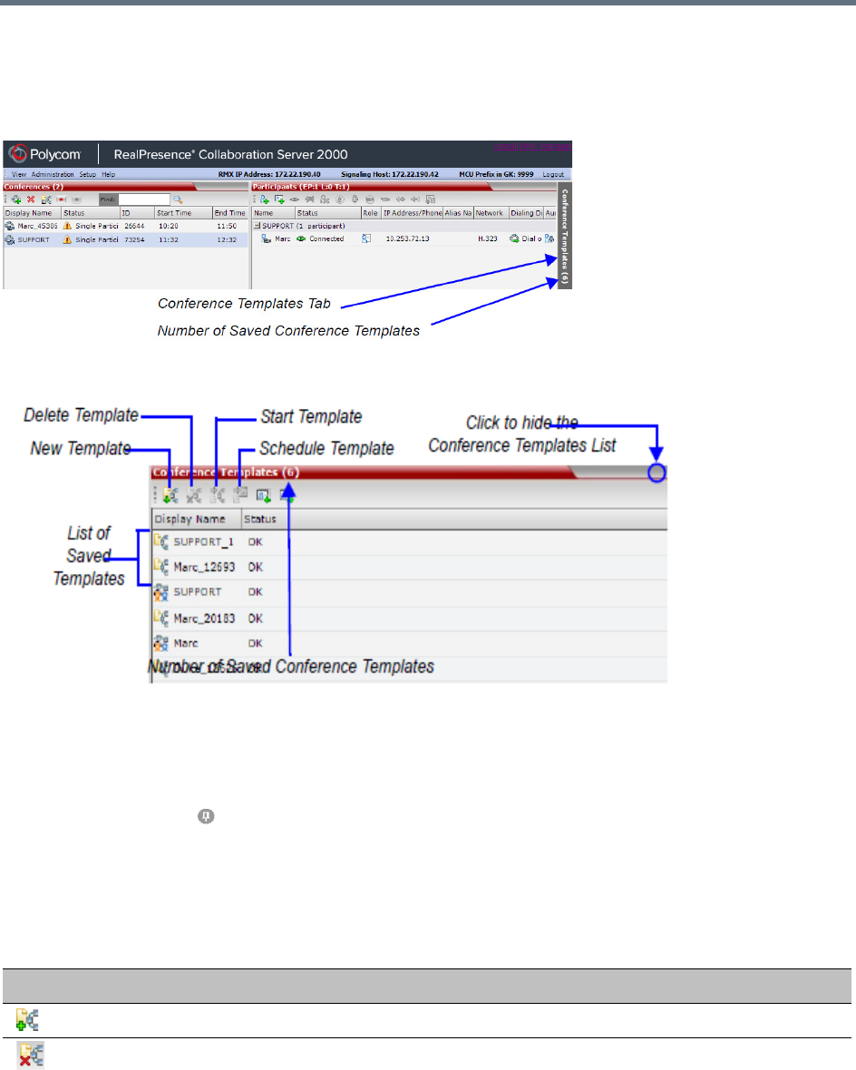
Conference Templates
Polycom®, Inc. 351
Using Conference Templates
The Conference Templates list is initially displayed as a closed tab in the Collaboration Server Web Client
main window. The number of saved Conference Templates is indicated on the tab.
Clicking the tab opens the Conference Templates list.
The Conference Templates are listed by Conference Template Display Name and ID and can be sorted by
either field. The list can be customized by re-sizing the pane, adjusting the column widths or changing the
order of the column headings.
For more information see Customizing the Main Screen.
Clicking the anchor pin ( ) button hides the Conference Templates list as a closed tab.
Toolbar Buttons
The Conference Template toolbar includes the following buttons:
Conference Templates – Toolbar Buttons
Button Description
New Conference Template Creates a new Conference Template.
Delete Conference Template Deletes the Conference Template(s) that are selected in the list.
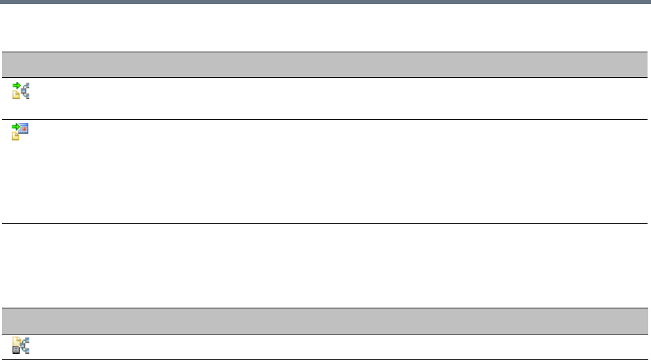
Conference Templates
Polycom®, Inc. 352
The Conferences List toolbar includes the following button:
Creating a New Conference Template
There are two methods to create a Conference Template:
●From scratch - defining the conference parameters and participants
●Saving an ongoing conference as Template
Creating a new Conference Template from Scratch
To create a new Conference Template:
1In the Collaboration Server main screen, click the Conference Templates pane.
Start Conference from Template Starts an ongoing conference from the Conference Template that has
an identical name, ID parameters and participants as the template.
Schedule Reservation from Template Creates a conference Reservation from the Conference Template
with the same name, ID, parameters and participants as the
Templ at e.
Opens the Scheduler dialog box enabling you to modify the fields
required to create a single or recurring Reservation based on the
template. For more information see Scheduling Reservations.
Conferences List – Toolbar Button
Button Description
Save Conference to Template Saves the selected ongoing conference as a Conference Template.
Conference Templates – Toolbar Buttons
Button Description
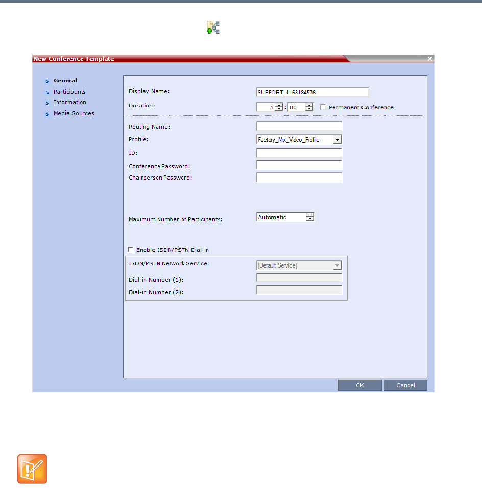
Conference Templates
Polycom®, Inc. 353
2Click the New Conference Template ( ) button.
The New Conference Template - General dialog box opens.
The fields of the New Template – General dialog box are identical to those of the New Conference
– General dialog box. For more information, see General Tab.
3Modify the fields of the General dialog box.
A unique dial-in number must be assigned to each conferencing entity. However, Conference
Templates can be assigned dial-in numbers that are already assigned to other conferencing entities,
but when the template is used to start an ongoing conference or schedule a reservation, it will not start
if another ongoing conference, Meeting Room, or Entry Queue or Gateway Profile is using this
number.
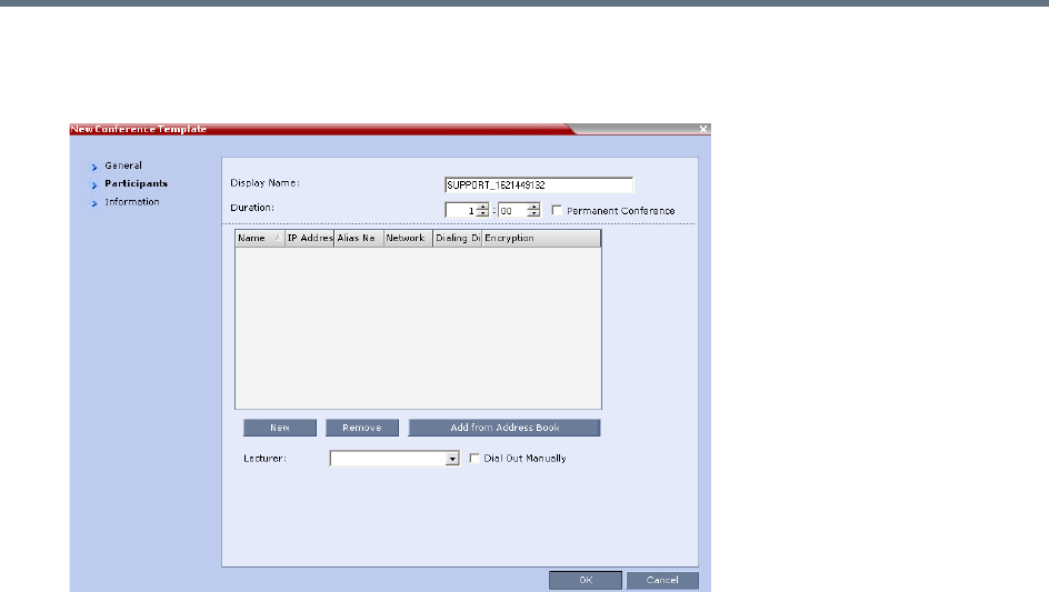
Conference Templates
Polycom®, Inc. 354
4Click the Participants tab.
The New Template – Participants dialog box opens.
Specify the Display Name or Duration.
To have a permanent conference, select the Permanent Conference check box.
The fields of the New Template – Participants dialog box are the same as those of the New
Conference – Participant dialog box.
5You can add participants to the template from the Address Book as desired.
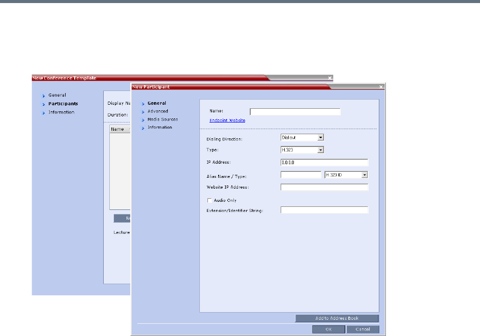
Conference Templates
Polycom®, Inc. 355
6Click the New button.
The New Participant – General dialog box opens.
The New Template – Participant dialog box remains open in the background.
For a full description of the General tab fields see Adding a New participant to the Address Book
Directly.
7Modify the fields of the General dialog box.
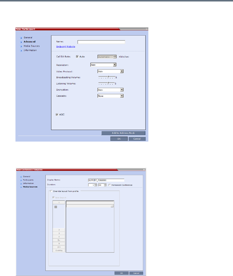
Conference Templates
Polycom®, Inc. 356
8Click the Advanced tab.
The New Participant – Advanced dialog box opens.
9Modify the fields of the Advanced dialog box.
10 Click the Media Sources tab.
The Media Sources dialog box opens.
The Media Sources dialog box enables you to set up and save, Display Name, Duration and
Personal Layout and Video Forcing settings for each participant. This is especially important when
setting up Telepresence conferences.
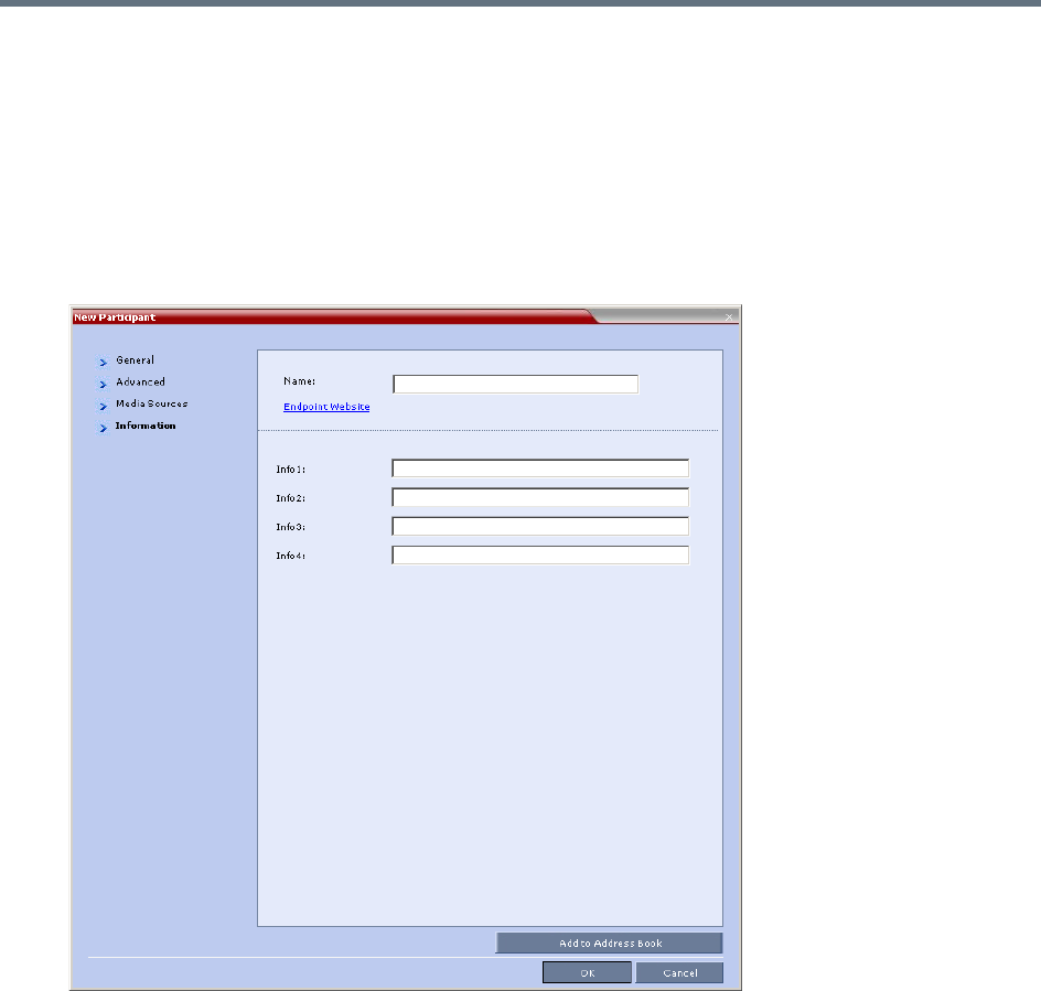
Conference Templates
Polycom®, Inc. 357
11 Specify the Display Name and Duration.
To have a permanent conference, select the Permanent Conference check box.
12 Modify the Personal Layout and Video Forcing settings for the participant, and select Override
layout from Profile if needed.
For Configuring Personal Layout and Video Forcing functions, see configurations on Video Settings
tab in Defining AVC-Based Conference Profiles.
13 To add any optional information, click the Information tab.
The New Participant – Information dialog box opens.
For more information, see Information Tab.
14 Click the OK button.
The participant you have defined is added to the Participants List.
The New Participant dialog box closes and you are returned to the New Template – Participant
dialog box (which has remained open since step 6).
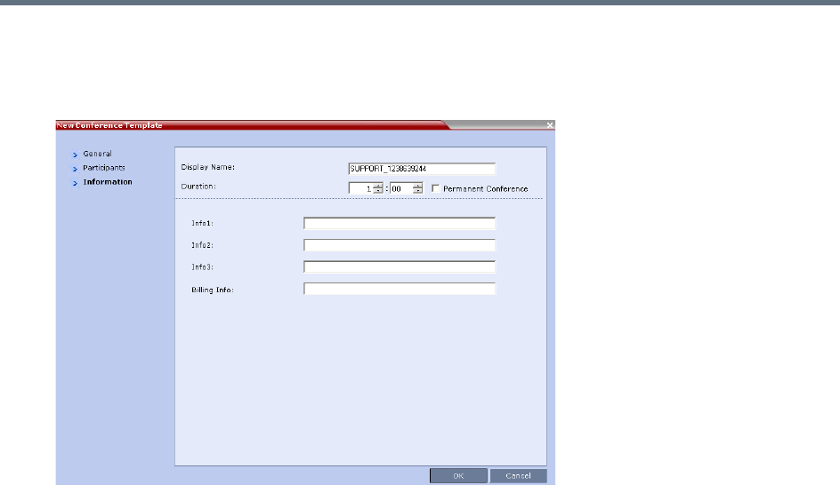
Conference Templates
Polycom®, Inc. 358
15 To add any optional information, in the New Conference Template dialog box, click the Information
tab.
The New Conference Template – Information dialog box opens.
For more information, see Information Tab.
16 Click the OK button.
The New Conference Template is created and its name is added to the Conference Templates list.
Saving an Ongoing or AVC-CP Operator Conference as a Template
Any ongoing or AVC-based CP Operator Conference can be saved as a template.
To save an ongoing or AVC-based CP Operator Conference as a template:
1In the Conferences List, select the conference or Operator Conference to be saved as a Template.
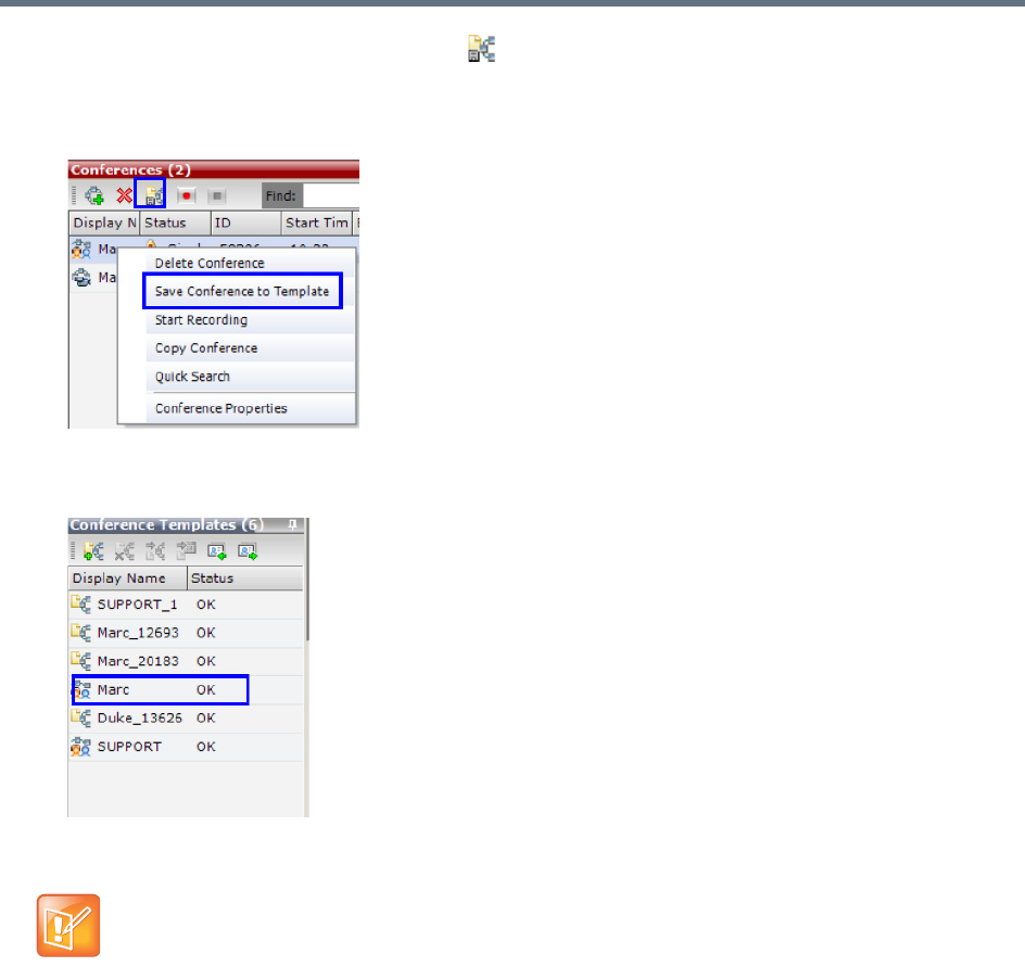
Conference Templates
Polycom®, Inc. 359
2Click the Save Conference to Template () button.
or
Right-click and select Save Conference to Template.
The conference is saved to a template whose name is taken from the ongoing conference Display
Name (the Login name of the Collaboration Server User). The Template is displayed with the
Operator Conference icon.
Starting an Ongoing Conference From a Template
An ongoing conference can be started from any Template saved in the Conference Templates list. In
SVC-based templates, only defined dial-in participants may be part of the conference.
To start an ongoing conference from a Template:
1In the Conference Templates list, select the Template you want to start as an ongoing conference.
Conference Templates saved from an ongoing conference does not include Message Overlay text
messages.
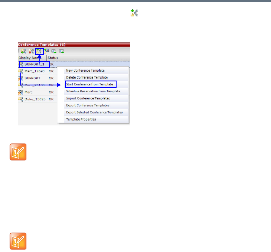
Conference Templates
Polycom®, Inc. 360
2Click the Start Conference from Template () button.
or
Right-click and select Start Conference from Template.
The conference is started.
The name of the ongoing conference in the Conferences list is taken from the Conference Template
Display Name.
Participants that are connected to other ongoing conferences when the template becomes an
ongoing conference are not connected.
Starting an Operator Conference from a Template (AVC Conferencing)
An ongoing Operator conference can be started from an Operator Template saved in the Conference
Templates list.
To start an ongoing Operator conference from an Operator Template:
1In the Conference Templates list, select the Operator Template to start as an ongoing Operator
conference.
If a Conference Template is assigned a dial-in number that is already assigned to an ongoing
conference, Meeting Room, or Entry Queue or Gateway Profile, when the template is used to start an
ongoing conference or schedule a reservation it will not start. However, the same number can be
assigned to several conference templates provided they are not used to start an ongoing conference
at the same time. If a dial in number conflict occurs prior to the conference’s start time, an alert is
displayed: ISDN dial-in number is already assigned to another conferencing
entity and the conference cannot start.
If an ongoing conference, Meeting Room or Entry Queue with the same Display Name, Routing Name
or ID already exists in the system, the conference will not be started.
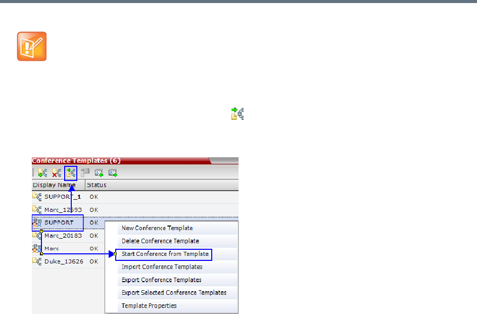
Conference Templates
Polycom®, Inc. 361
2Click the Start Conference from Template () button.
or
Right-click and select Start Conference from Template.
The conference is started.
The name of the ongoing conference in the Conferences list is taken from the Conference Template
Display Name.
Scheduling a Reservation From a Conference Template
A Conference Template can be used to schedule a single or recurring Reservation.
To schedule a Reservation from a Conference Template:
1In the Conference Templates list, select the Conference Template you want to schedule as a
Reservation.
•You can only start an Operator conference from a template whose name is identical to your Login
Name. For example, if your Login name is Polycom, you can only start an Operator conference from
a template whose name is Polycom.
•If an ongoing Operator conference with the same name or any other conference with the same ID
is already running, you cannot start another Operator conference with the same login name.
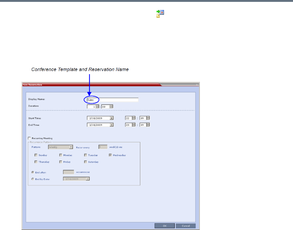
Conference Templates
Polycom®, Inc. 362
2Click the Schedule Reservation from Template () button.
or
Right-click and select Schedule Reservation from Template.
The Reservation Properties dialog box is displayed.
The Display Name of the Reservation is taken from the Conference Template Display Name.
For a full description of the Reservation Properties fields see Creating a New Reservation.
3Modify the fields of the Reservation Properties.

Conference Templates
Polycom®, Inc. 363
4Click the OK button.
A Reservation is created based on the Conference Template. The Reservation can be viewed and
modified along with all other Reservations using the Reservations - Calendar View and Reservations
List.
If you create a recurring reservation all occurrences have the same ID. A recurring Reservation is
assigned the same ISDN/PSTN dial-in number for all recurrences.
If a dial-in number conflict occurs prior to the conference’s start time, an alert is displayed: ISDN
dial-in number is already assigned to another conferencing entity and the
conference cannot start.
The series number (_0000n) of each reservation is appended to its Display Name.
Example:
Conference Template name: Sales
Display Name for single scheduled occurrence: Sales
If 3 recurrences of the reservation are created:
Display Name for occurrence 1: Sales_00001
Display Name for occurrence 2: Sales_00002
Display Name for occurrence 3: Sales_00003
Deleting a Conference Template
One or several Conference Templates can be deleted at a time.
To delete Conference Templates:
1In the Conference Templates list, select the Template(s) you want to delete.
2Click the Delete Conference Template () button.
or
Right-click and select Delete Conference Template.
A confirmation dialog box is displayed.
3Click the OK button to delete the Conference Template(s).
Exporting and Importing Conference Templates
Conference Templates can be exported from one MCU and imported to multiple MCUs in your environment.
Additionally, you can export Conference Templates and their associated Conference Profiles
simultaneously. Using this option can save configuration time and ensures that identical settings are used
for conferences running on different MCUs. This is especially important in environments using cascading
conferences that are running on different MCUs.
●Administrators can export and import Conference Templates. Operators are only allowed to export
Conference Templates.
●You can select a single, multiple or all Conference Templates to be exported.
●Both Conference Templates and their associated Conference Profiles can be exported and imported
simultaneously when enabling the Export includes conference profiles or Import includes conference
profiles options.
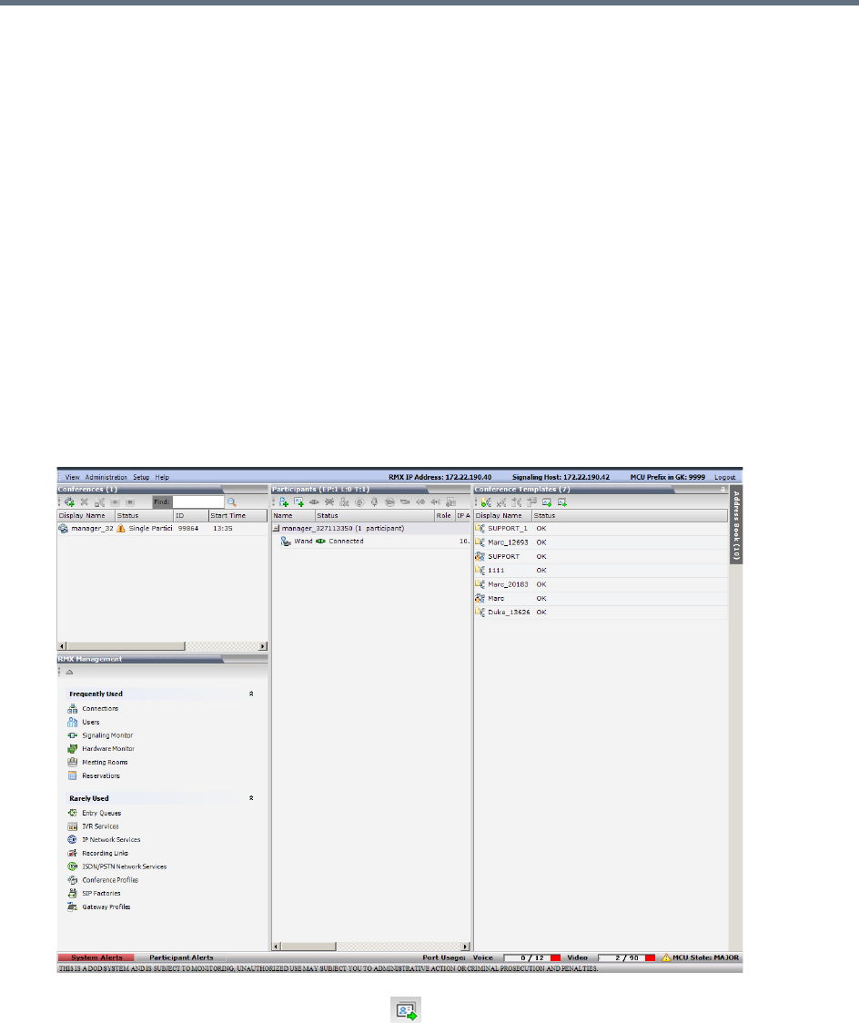
Conference Templates
Polycom®, Inc. 364
●Exporting and importing Conference Templates only can be used when you want to export and import
individual Conference Templates without their associated Conference Profiles. This option enables
you to import Conference Templates when Conference Profiles already exist on an MCU.
Exporting Conference Templates
Conference Templates are exported to a single XML file that can be used to import the Conference
Templates on multiple MCUs.
Using the Export Conference Templates option, you can:
●Export all Conference Templates from an MCU
●Export selected Conference Templates
Exporting All Conference Templates from an MCU
To export all Conference Templates from an MCU:
1In the Collaboration Server Web Client main window, click the Conference Templates tab.
The Conference Templates list pane is displayed.
2Click the Export Conference Templates button, or right-click the Conference Templates list,
and then select Export Conference Templates.
The Conference Templates - Export dialog box is displayed.
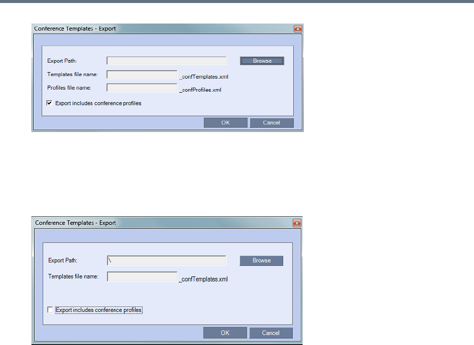
Conference Templates
Polycom®, Inc. 365
3In the Export Path field, type the path name to the location where you want to save the exported file
or click Browse to select the desired path.
4If you wish to clear the Export includes conference profiles check box when you only want to
export Conference Templates.
When this check box is cleared, the Conference Templates - Export dialog box is displayed without
the Profiles file name field.
5In the Templates file name field, type the file name prefix. The file name suffix
(_confTemplates.xml) is predefined by the system. For example, if you type Templates01, the
exported file name is defined as Templates01_confTemplates.xml.
The system automatically defines the Profiles file name field with the same file name prefix as the
Templates file name field. For example, if you type Templates01 in the Templates file name field, the
exported profiles file name is defined as Templates01_confProfiles.xml.
6Click OK to export the Conference Templates and Conference Profiles to a file.
Exporting Selected Conference Templates
You can export a single Conference Template or multiple Conference Templates to other MCUs in your
environment.
To export selected Conference Templates:
1In the Conference Templates list, select the templates you want to export.
2Right-click the Conference Templates to be exported, and then click Export Selected Conference
Templates.
The Conference Templates - Export dialog box is displayed.
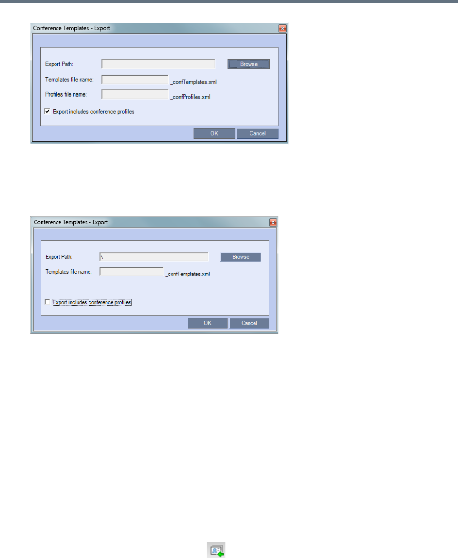
Conference Templates
Polycom®, Inc. 366
3In the Export Path field, type the path name to the location where you want to save the exported file
or click Browse to select the desired path.
4To export Conference Templates, clear the Export includes conference profiles check box.
When this check box is cleared, the Conference Templates - Export dialog box is displayed without
the Profiles file name field.
5In the Templates file name field, type the file name prefix. The file name suffix
(_confTemplates.xml) is predefined by the system. For example, if you type, Templates01, the
exported file name is defined as Templates01_confTemplates.xml.
The system automatically defines the Profiles file name field with the same file name prefix as the
Templates file name field. For example, if you type Templates01 in the Templates file name field, the
exported profiles file name is defined as Templates01_confProfiles.xml.
6Click OK to export the Conference Templates and Conference Profiles to a file.
Importing Conference Templates
You can import Conference Templates and Conference Profiles from one MCU to multiple MCUs in your
environment.
To import Conference Templates:
1In the Collaboration Server Web Client main window, click the Conference Templates tab.
The Conference Templates are displayed.
2Click the Import Conference Templates button, or right-click the Conference Templates pane,
and then click Import Conference Templates.
The Conference Templates - Import dialog box is displayed.
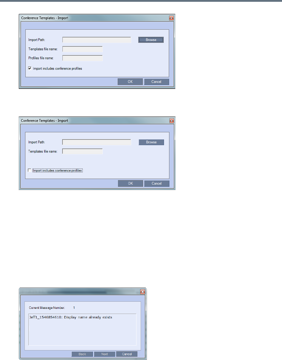
Conference Templates
Polycom®, Inc. 367
3To import Conference Templates, clear the Import includes conference profiles check box.
When this check box is cleared, the Conference Templates - Import dialog box is displayed without
the Profiles file name field.
4In the Import Path field, click Browse to navigate to the path and file name of the Conference
Templates you want to import.
When clicking the exported templates file you want to import, the system automatically displays the
appropriate files in the Templates file name field and the Profiles file name field (when the Import
includes conference profiles check box is selected).
5Click OK to import the Conference Templates and their associated Conference Profiles, if selected.
Conference Templates are not imported when:
A Conference Template already exists
An associated Conference Profile is not defined in the Conference Profiles list
When one or more Conference Templates are not imported, a Message Alert window is displayed with
the templates that were not imported.

Conference Templates
Polycom®, Inc. 368
6Click Cancel to exit the Message Alerts window.
The imported Conference Templates are added to the Conference Templates list. When the Import
includes conference profiles check box is selected, the imported Conference Profiles are added to
the Conference Profiles list.

Polycom, Inc. 369
Start a Conference
There are several ways to start a conference:
●Clicking the New Conference button in the Conferences pane. For more information, see Start an
AVC CP Conference from the Conferences Pane and Starting a New SVC Conference.
●Dialing in to a Meeting Room.
A Meeting Room is a conference that is saved on the MCU. It remains in passive mode until it is
activated by the first participant, or the meeting organizer, dialing in.
For more information, see Meeting Rooms.
●Dialing in to an Ad Hoc Entry Queue which is used as the access point to the MCU. This option is
valid to AVC participants dialing into an AVC-based or a Mixed CP and SVC Entry Queue.
For more information, see Entry Queues, Ad Hoc Conferences and SIP Factories.
●Start a Reservation (AVC CP):
If the Start Time of the Reservation is past due the conference becomes ongoing immediately.
If the Start Time of the Reservation is in the future the conference becomes ongoing, at the
specified time on the specified date.
Changes made to this information once the conference is running are not saved to the CDR.
●Start any Conference Template saved in the Conference Templates list.
For more information, see Starting an Ongoing Conference From a Template.
●Clicking on the link included in a Microsoft Outlook Polycom Meeting Invitation or by manually dialing
the numbers displayed in the invitation using the endpoint's numeric input device.
This option is valid to AVC participants only.
Attendees that have received an invitation to a Polycom Meeting through the Polycom Conferencing
Add-in for Microsoft Outlook can start a conference by being the first invited attendee to click on a link
in the Meeting Invitation displayed on his/her workstation or calendaring enabled endpoint, or
manually dial in to the meeting using the Polycom Conference information included in the Meeting
Invitation.
For more information see Polycom Conferencing for Microsoft Outlook®.
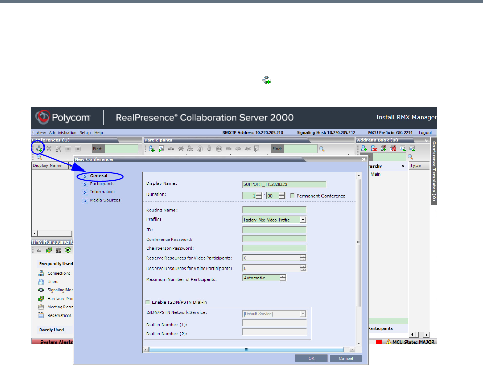
Start a Conference
Polycom, Inc. 370
Start an AVC CP Conference from the Conferences Pane
To start an AVC CP conference from the Conference pane:
1In the Conferences pane, click New Conference ().
The New Conference – General dialog box opens.
2Set general information, such as meeting duration, meeting profile, and passwords. For more
information, see General Tab.
3Click the Participants tab to add participants from the Participants Address Book or to define
participants (mainly dial-out participants). For more information, see Participants Tab.
4If all participants are undefined, dial-in, and no additional information is required for the new
conference, click OK.
The system displays the conference default Name, Duration and the default Profile, which contains
the conference parameters and media settings.
The system automatically allocates the conference ID when the conference starts.
In most cases, the default conference ID can be used and you can just click OK to launch the
conference. If required, you can enter a conference ID before clicking OK to launch the conference.
If you are the meeting chairperson or organizer using the Collaboration Server Web Client to start
your own meeting, you need to communicate the default conference ID (or the one you created) to
the other conference participants so that they can dial in.
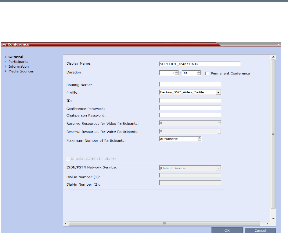
Start a Conference
Polycom, Inc. 371
General Tab
You can define parameters such as your display name, conference profile, conference password, and
duration in the General tab.
The following table describes the information displayed in the General Tab.

Start a Conference
Polycom, Inc. 372
New Conference - General tab parameters
Field Description
Display Name The Display Name is the conferencing entity name in native language character sets to
be displayed in the RP Collaboration Server Web Client.
In conferences, Meeting Rooms, Entry Queues and SIP factories the system
automatically generates an ASCII name for the Display Name field that can be
modified using Unicode encoding.
•
English text uses ASCII encoding and can contain the most characters (length varies
according to the field).
•European and Latin text length is approximately half the length of the maximum.
•Asian text length is approximately one third of the length of the maximum.
The maximum length of text fields also varies according to the mixture of character
sets (Unicode and ASCII).
Maximum field length in ASCII is 80 characters.
If the same name is already used by another conference, Meeting Room or Entry
Queue, the Collaboration Server displays an error message requesting you to enter a
different name.
Note: This field is displayed in all tabs.
Duration Define the duration of the conference in hours using the format HH:MM (default 01:00).
Note: This field is displayed in all tabs.
Permanent Conference Click this check box to make this conference a Permanent Conference: an ongoing
conference with no pre-determined End Time, continuing until it is terminated by an
administrator, operator or chairperson. For more information see Audio Algorithm
Support.
Note: This field is displayed in all tabs.
Routing Name Routing Name is the name with which ongoing conferences, Meeting Rooms, Entry
Queues and SIP Factories register with various devices on the network such as
gatekeepers and SIP servers. This name must be defined using ASCII characters.
Comma, colon and semicolon characters cannot be used in the Routing Name.
The Routing Name can be defined by the user or automatically generated by the
system if no Routing Name is entered as follows:
•If ASCII characters are entered as the Display Name, it is used also as the Routing
Name
•If a combination of Unicode and ASCII characters (or full Unicode text) is entered as
the Display Name, the ID (such as Conference ID) is used as the Routing Name.
If the same name is already used by another conference, Meeting Room or Entry
Queue, the Collaboration Server displays an error message and requests that you
enter a different name.
Profile The system displays the name of the default Conference Profile. Select the required
Profile from the list.
The Conference Profile includes the conferencing mode, conference line rate, media
settings and general settings.
For a detailed description of Conference Profiles, see Using Conference Profiles.

Start a Conference
Polycom, Inc. 373
ID Enter the unique-per-MCU conference ID. If left blank, the MCU automatically assigns
a number once the conference is launched.
This ID must be communicated to conference participants to enable them to dial in to
the conference.
Note: If setting the Conference ID to the digits that are used for MCU prefix in
Gatekeeper (for example gatekeeper prefix is set to 10 and the conference ID is 1001),
the system will not be able to dial to the destination conference as the prefix digits are
truncated from the conference ID, preventing the system from locating it.
Note: If SIP Factories are used do not use the number 7001 as an ID. 7001 is the
default SIP Factory ID.
Conference Password Enter a password to be used by participants to access the conference. If left blank, no
password is assigned to the conference.
This password is valid only in conferences that are configured to prompt for a
conference password.
This field is numeric and has a default length of 4 characters. The administrator can
modify it in the Setup >System Configuration settings. For more information, see
System Configuration Flags.
The Collaboration Server can be configured to automatically generate conference (and
chairperson) passwords when these fields are left blank. For more information, see
Automatic Password Generation Flags.
Chairperson Password Enter a password to be used by the Collaboration Server to identify the Chairperson
and grant him/her additional privileges. If left blank, no chairperson password is
assigned to the conference. This password is valid only in conferences that are
configured to prompt for a chairperson password.
This field is numeric and has a default length of 4 characters. The administrator can
modify it in the Setup > System Configuration settings. For more information, see
System Configuration Flags.
The RealPresence Collaboration Server can be configured to automatically generate
chairperson (and conference) passwords when these fields are left blank. For more
information, see Automatic Password Generation Flags.
Reserve Resources for
Video Participants
(Collaboration Server
1500/2000/4000 only)
Enter the number of video participants for which the system must reserve resources.
Default: 0 participants.
Maximum:
•x Mode: 60 participants (Double card assembly)
•x Mode: 30 participants (Single card assembly)
Reserve Resources for
Audio Participants
(Collaboration Server
1500/2000/4000 only)
Enter the number of audio participants for which the system must reserve resources.
Voice resources must be allocated in the Video/Voice Port Allocation dialog box.
Default: 0 participants.
Maximum:
•x Mode: 720 participants (Double card assembly, with all ports are set to Audio
Only).
•x Mode: 360 participants (Single card assembly, with all ports are set to Audio Only).
New Conference - General tab parameters
Field Description
Start a Conference
Polycom, Inc. 374
Maximum Number of
Participants
Indicate the total number of participants that can be connected to the conference. The
automatic setting indicates that the maximum number of participants that can be
connected to the conference is determined according to resource availability.
Note: If a number is specified, it should be large enough to accommodate the
participants specified in the Reserve Resources for Video/Voice Participants fields.
Enable ISDN/PSTN
Dial-in
Select this check box if you want ISDN and PSTN participants to be able to connect
directly to the conference.
ISDN/PSTN Network
Service
The default Network Service is automatically selected. A different ISDN/PSTN Network
Service can be selected from the Network Services list.
Dial-in Number (1) Leave this field blank to let the system automatically assign a number from the dial-in
range defined for the selected ISDN/PSTN Network Service. To manually define a
dial-in number, enter a unique number from the dial-in number range defined for the
selected Network Service. This number cannot be assigned to another
Conference/Reservation/Meeting Room/Gateway Profile
Dial-in Number (2) By default, the second dial-in number is not defined. To define a second dial-in number,
enter a required number from the dial-in number range defined for the selected
Network Service.
New Conference - General tab parameters
Field Description
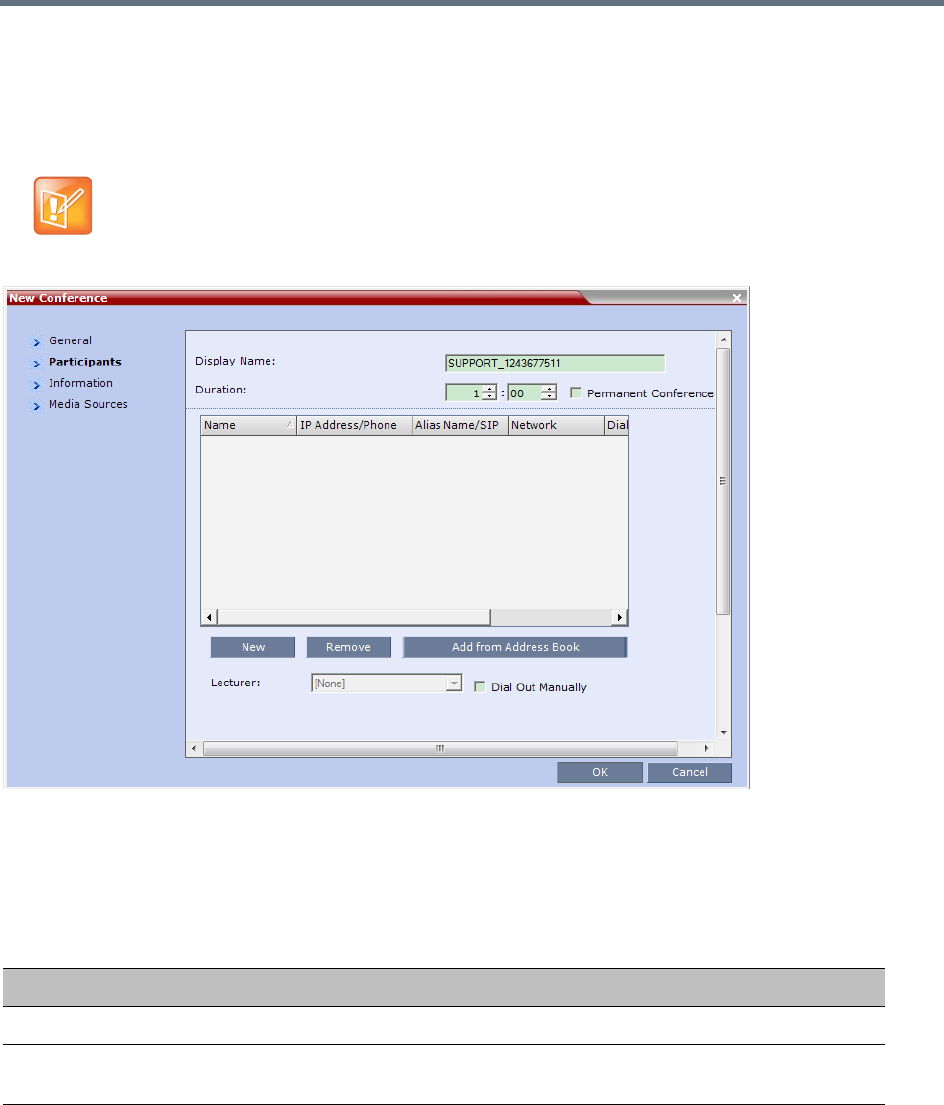
Start a Conference
Polycom, Inc. 375
Participants Tab
The Participants tab is used to add participants to the conference from the Address Book or by defining
them. Defined dial-out participants are connected to the conference automatically when the conference is
launched, unless the Dial Out Manually option is selected.
When defining a new conference, the Participants List is empty.
The following table describes the information displayed in the Participants List and the operations that can
be performed.
This procedure is optional.
New Conference – Participants Tab
Column / Button Description
Participants List
Name A Unicode field that displays the participant’s name and an icon representing the
endpoint type: Voice or Video.
IP Address/Phone Indicates the IP address or phone number of the participant’s endpoint.
•For dial-out connection, displays the IP address or phone number of the
endpoint called by the RealPresence Collaboration Server.
•For dial-in connection, displays the participant’s IP address or phone number
used to identify and route the participant to the appropriate conference.
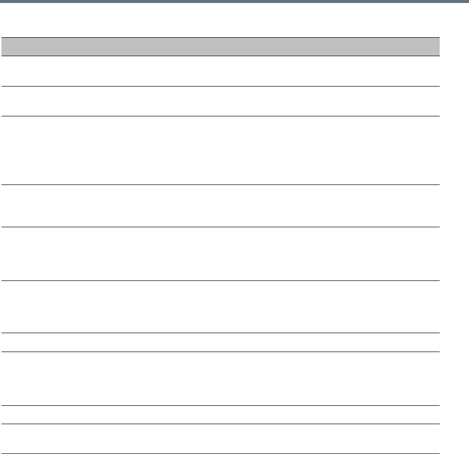
Start a Conference
Polycom, Inc. 376
Participants can be added to the conference in the following methods:
●Defining a new participant during the definition of the conference (clicking the New button).
●Adding pre-defined participants from the Address Book by either selecting the participants from the
list or dragging and dropping the participants from the Address Book to the Participants list.
●Dial-in participants can connect to the conference after it was started (without using the New
Conference - Participants dialog box).
●Once the conference has started, participants can be added to a conference directly from the
Participants Address Book without having to use the New Conference – Participants tab.
Alias Name/SIP
Address (IP Only)
Displays the alias name of an H.323 endpoint or the SIP URL.
Network The network communication protocol used by the endpoint to connect to the
conference: IP (H.323 or SIP) or ISDN/PSTN.
Dialing Direction Select the dialing direction:
• Dial-in – The participant dials in to the conference. This field applies to IP
participants only.
• Dial-out – The MCU dials out to the participant.
Note: Dial-out is forced when defining an ISDN/PSTN participant.
Encryption Displays whether the endpoint uses encryption for its media.
The default setting is Auto, indicating that the endpoint must connect according to
the conference encryption setting.
Lecturer This option is used to activate the Lecture Mode. Select the participant you want to
designate as Lecturer from the list of conference participants.
The Lecturer can be selected once the conference is running and participants are
connected.
Dial Out Manually Select this option to designate a Collaboration Server User-controlled dial-out
conference connection. When checked, the user must connect each of the dial-out
participants who remain on standby until they are connected to the conference.This
option is disabled in SVC conferences.
Buttons
New Click to define a new participant.
For more information, see Polycom® RealPresence Collaboration Server (RMX)
1500/1800/2000/4000 Administrator’s Guide, Adding a New participant to the
Address Book Directly.
Remove Click to remove the selected participant from the conference.
Add from Address
Book
Click to add a participant from the Address Book to the conference.
New Conference – Participants Tab (continued)
Column / Button Description
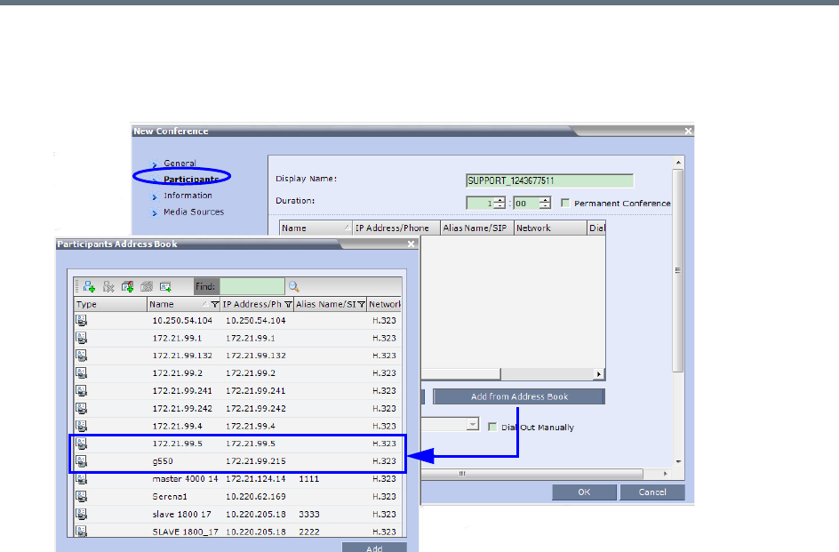
Start a Conference
Polycom, Inc. 377
To add participants from the Address Book:
1In the Participants List, click the Add from Address Book button to open the Participants Address
Book.
The All Participants list opens.
2In the Participants Address Book, select the participants that you want to add to the conference and
click the Add button.
Standard Windows multiple selection techniques can be used in this procedure.
3The selected participants are assigned to the conference and appear in the Participant List.
4Select additional Participants or click the Close button to return to the Participants tab.
Information Tab
In the Info fields, you can add general information about the conference, such as contact person name,
company name, billing code, etc.
This information is written to the Call Detail Record (CDR) when the conference is launched.
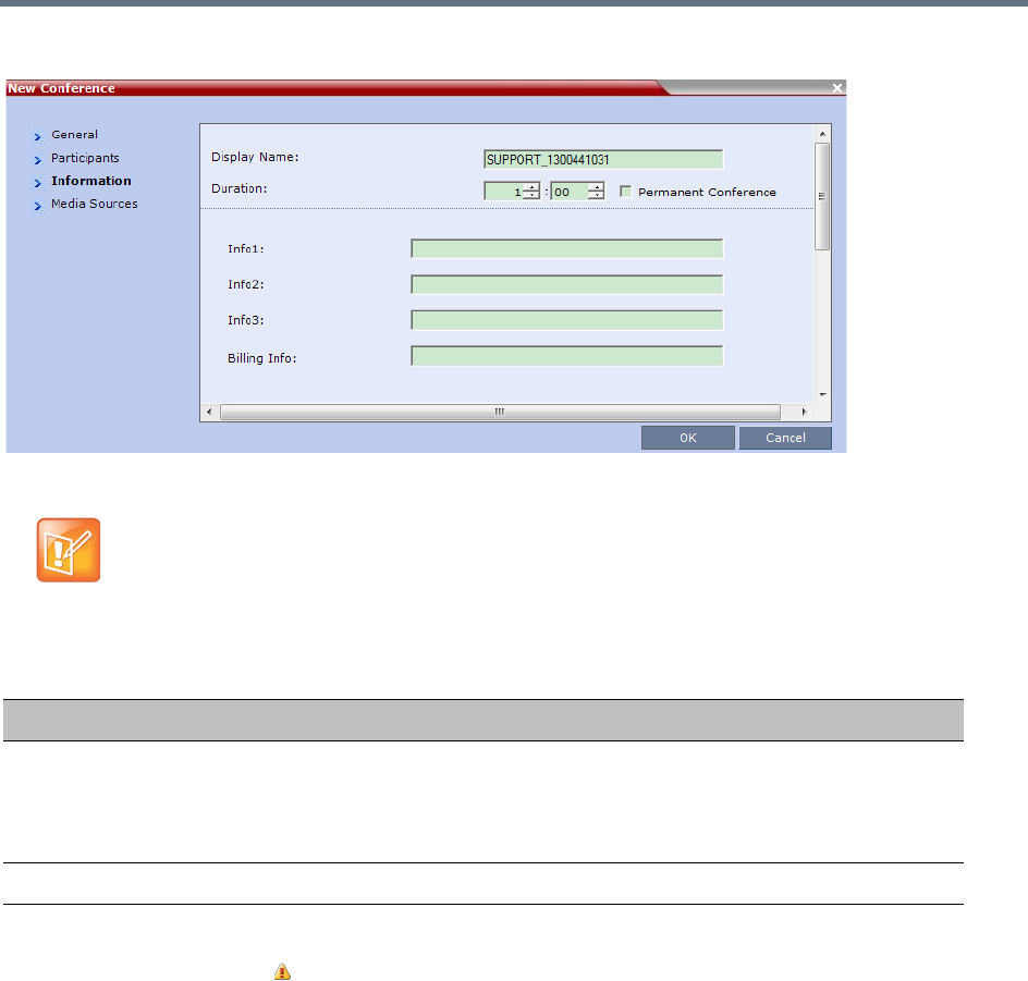
Start a Conference
Polycom, Inc. 378
Changes made to this information once the conference is running are not saved to the CDR.
If no participants were defined for the conference or as long as no participants are connected, the indication
Empty and a warning icon ( ) appear in the Status column in the Conferences pane.
The status changes when participants connect to the conference.
If no participant connects within the time specified in the Conference Profiles > Auto Terminate > Before
First Joins field, the conference is automatically terminated by the system.
Media Sources Tab
You can define a new layout, and override the original layout that defined in the Conference Profile.
Furthermore you can define any participant into a specific window in the new layout. For more information,
see Video Forcing (AVC-Based CP and Mixed CP and SVC Conferences).
This procedure is optional.
The information entered into these fields does not affect the conference.
New Conference – Information Tab
Field Description
Info1, 2, 3 There are three information fields that allow you to enter general information for
the conference such as company name, contact person etc.
Unicode can be used in these fields.
The maximum length of each field is 80 characters.
Billing Enter the conference billing code if applicable.
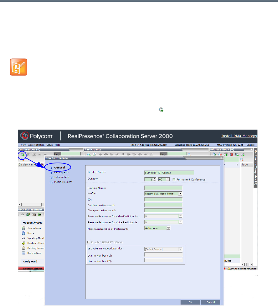
Start a Conference
Polycom, Inc. 379
Starting a Mixed CP and SVC or SVC Only Conference from the
Conferences Pane
Starting a New SVC Conference
To start a SVC conference from the Conference pane:
1In the Conferences pane, click the New Conference ( ) button.
The New Conference – General dialog box opens.
2Select a Profile set to SVC or Mixed CP and SVC Conferencing Mode.
3Set parameters in the General, Information, Media Sources, and Participants tabs.
For more information on parameters, see General Tab, Participants Tab, Information Tab, and Media
Sources Tab.
•SA license is required for SVC conferencing.
•In mixed AVC/SVC conferences, participants with SVC-enabled endpoints and AVC endpoints can
participate in the same conference.
•During mixed SVC & CP conferences, PSTN (Audio Only) calls are also supported.
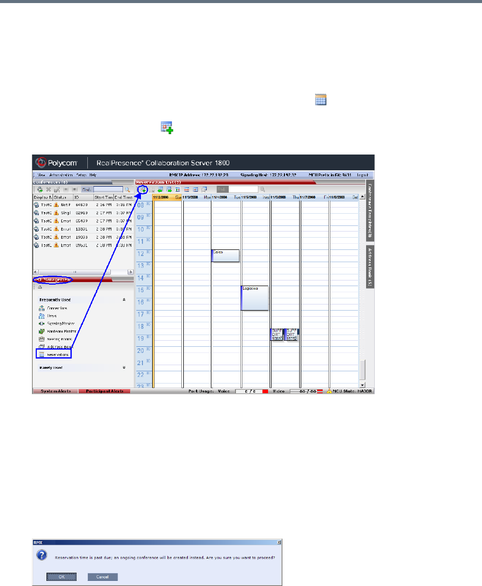
Start a Conference
Polycom, Inc. 380
Scheduling an AVC-based Reservation
AVC-based Reservations are started by selecting an AVC-based Profiles.
To start a conference from the Reservation Calendar:
1In the RMX Management pane, click the Reservations entry ( ). The Reservation Calendar is
displayed.
2Click the New Reservation ( ) button.
The New Reservation – General tab dialog box is displayed.
This dialog box is identical to the AVC CP New Conference - General dialog box. For a field
description, see General Tab.
3 Optional. Select the Enable ISDN/PSTN Dial-in check box if you want ISDN and PSTN participants
to be able to connect directly to the conference.
4If Enable ISDN/PSTN Dial-in option is selected, either enter a dial-in number, or leave the Dial-in
Number field blank to let the system automatically assign a number from the dial-in range defined
for the selected ISDN/PSTN Network Service.
5Click the OK button.
A confirmation box is displayed stating that the Reservation time is past due and that the conference
will become ongoing.
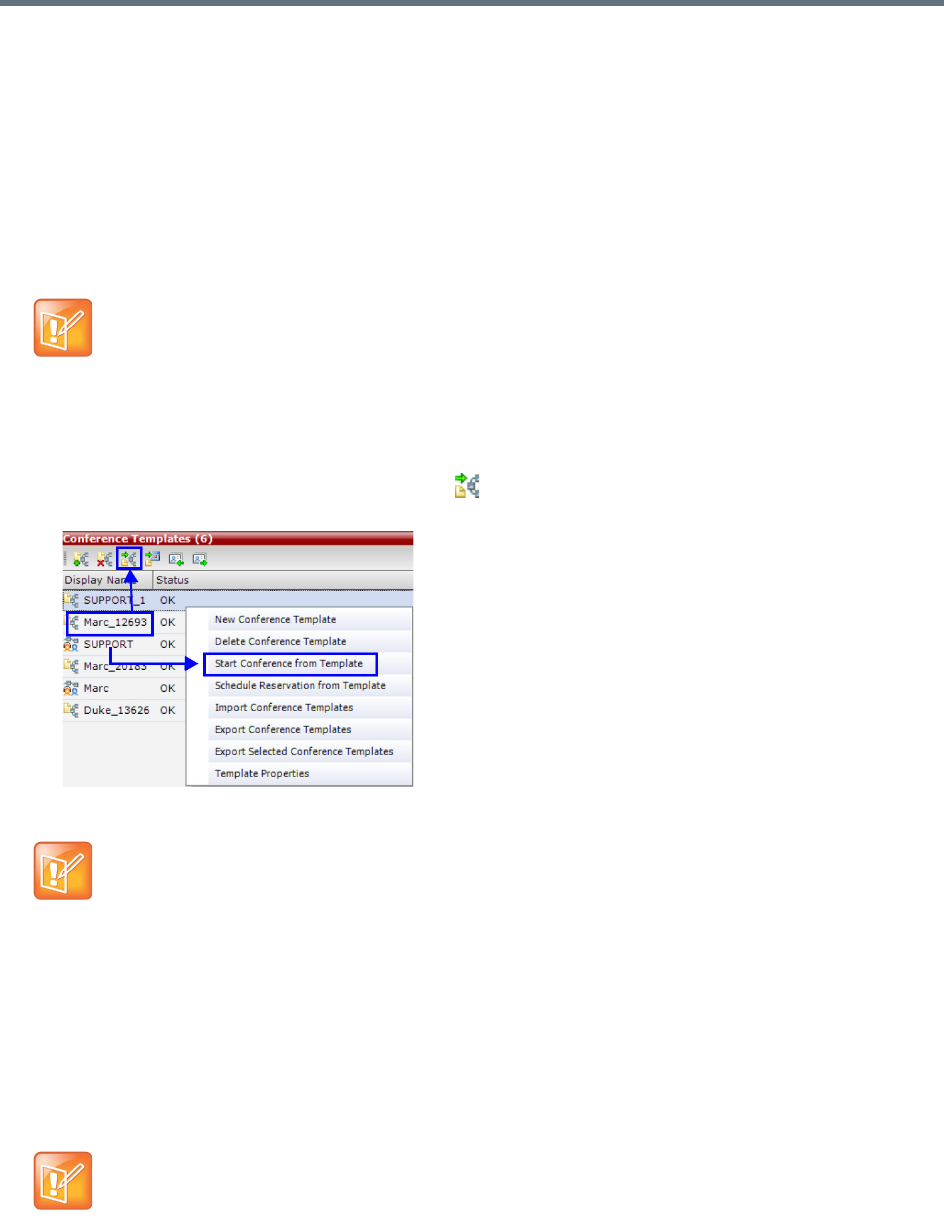
Start a Conference
Polycom, Inc. 381
6Click OK.
The conference is started. If applicable, an ISDN/PSTN dial-in number was assigned to the
conference either automatically or manually, this number can be viewed in the Conferences pane.
For more information about Reservations, see Scheduling Reservations.
Starting an Ongoing Conference From a Template
An ongoing conference can be started from any Conference Template saved in the Conference Templates
list.
To start an ongoing conference from a template:
1In the Conference templates list, select the template you want to start as an ongoing conference.
2Click the Start Conference from Template () button, or right-click and select Start Conference
from Template.
The conference is started.
The name of the ongoing conference in the Conferences list is taken from the conference template
Display Name.
Participants that are connected to other ongoing conferences when the template becomes an
ongoing conference are not connected.
SVC-based Conference Templates cannot be saved with dial-out participants, only dial-in SIP
participants may be defined.
If an AVC-based CP Conference Template is assigned an ISDN/PSTN dial-in number that is already
assigned to an ongoing conference, Meeting Room, Entry Queue or Gateway Profile, when the
template is used to start an ongoing conference or schedule a reservation it will not start. However,
the same number can be assigned to several conference templates provided they are not used to
start an ongoing conference at the same time. If a dial in number conflict occurs prior to the
conference’s start time, an alert appears: “ISDN dial-in number is already assigned to another
conferencing entity” and the conference cannot start.
If an ongoing conference, Meeting Room or Entry Queue with the same Display Name, Routing
Name or ID already exist in the system, the conference will not be started.

Start a Conference
Polycom, Inc. 382
For detailed description of Conference Templates, see Conference Templates.
Starting a Meeting from Microsoft Outlook Using Polycom Add-in
Polycom Conferencing for Microsoft Outlook is an add-in that enables users to easily organize and invite
attendees to video enabled meetings via Microsoft Outlook®. For more information see Polycom
Conferencing for Microsoft Outlook®.
Using Polycom Conferencing add-in to Microsoft Outlook, an audio meeting can be created as any other
Outlook meeting. For more information, see Appendix H - Integration Into Microsoft Environments.
This section is applicable for CP-AVC only conferences.

Polycom, Inc. 383
Conference and Participant Level
Operations
Conference Operations
The Collaboration Server user can Copy and Paste conferences. When using the Collaboration Server Web
Client, conferences can be copied and pasted on the same MCU. However, when using the RMX Manager,
with its ability to manage multiple MCUs, conferences can be copied and pasted between different MCUs.
Copy Conference
The Copy command copies all the conference’s properties including connected participants and makes
these properties available for pasting and starting a new conference. The copied conference remains active
until it terminates or is deleted.
To copy a conference:
»In the Conferences List pane, right-click the conference you want to copy, and select Copy
Conference.
Paste Conference
The Paste Conference command starts the new conference on the same MCU or on a different MCU.
To paste a conference:
»Right-click in the Conferences List pane, and select Paste Conference.
or
If you are using the RMX Manager, and you want to paste the conference to a different MCU:
aIn the MCUs list pane, click the MCU in which to create the conference.
bIn the Conferences List pane, right-click, and select Paste Conference.
The conference is pasted to the MCU with its Display Name assigned by the system.
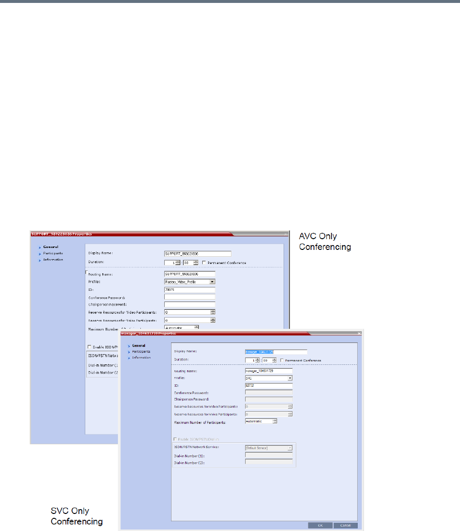
Conference and Participant Level Operations
Polycom, Inc. 384
Paste Conference As
The Paste Conference As command allows the system user to create a new conference using the copied
conference properties as a template. It automatically opens the Conference Properties dialog box allowing
the user to modify information in the General, Participants and Information tabs to create the new
conference. When the OK button in the Conference Properties dialog box conference Properties dialog
box is clicked, the new conference is started.
To paste a conference as a new conference:
1Right-click in the Conferences List pane, and select Paste Conference As.
or
If you are using the RMX Manager and you want to paste the conference to a different MCU:
aIn the MCUs list pane, click the MCU in which to create the conference.
bIn the Conferences List pane, right-click, and select Paste Conference As.
The Conference Properties dialog box is displayed.
2Modify the conference information as required.
3Click OK to paste and start the new conference.
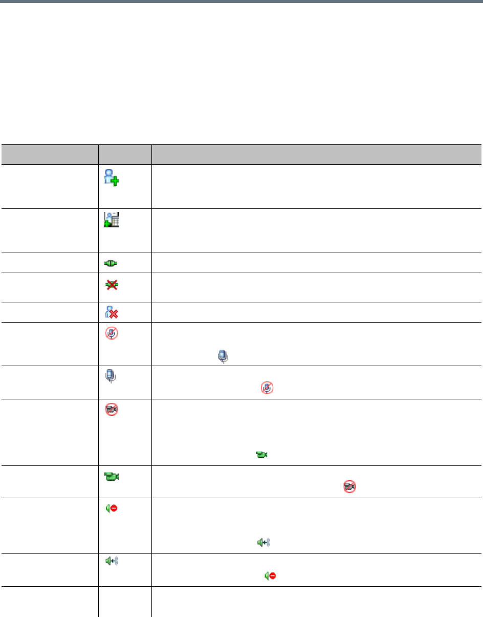
Conference and Participant Level Operations
Polycom, Inc. 385
Participant Operations
Operational Buttons
Various operations can be performed during an ongoing conference, affecting only the selected participants
in the conference. These operations enable you to modify and control the connections and statuses of
participants in ongoing conferences, as described in the following table.
Participant Level Operations
Menu Option Button Description
New Participant Define a new participant.
SVC dial-in participants can be added to SVC Only and Mixed CP and SVC
conferences. SVC dial-out participants cannot be added to any conference.
Add Participant
From Address Book
Open the Address Book to select the participant for the conference.
SVC dial-in participants can be added to SVC Only and Mixed CP and SVC
conferences. SVC dial-out participants cannot be added to any conference.
Connect Participant Connect a disconnected defined dial-out participant to the conference.
Disconnect
Participant
Disconnect the participant from the conference.
Delete Participant Delete the selected participants from the conference.
Mute Audio Mute the audio transmission from the participant to the conference.
The Audio Muted indicator appears in the Participants List and the Unmute
Audio button ( ) becomes active.
Unmute Audio Resume the participant’s audio transmission to the conference.
The Mute Audio button ( ) becomes active.
Suspend Video Suspend the video transmission from the participant to the conference. The
suppressed participant’s video is not transmitted to the conference but the
participant still receives conference video.
The Suspend Video indicator appears in the Participants List and the
Resume Video button ( ) becomes active.
Resume Video Resume the participant’s video transmission to the conference.
The Suspend Video button becomes active ( ).
Block Audio Block the audio transmission from the conference to the participant. When
blocked, the participant can still be heard by the conference.
The Audio Blocked indicator appears in the Participants List and the
Unblock Audio button ( ) becomes active.
Unblock Audio Resume the audio transmission from the conference to the participant.
The Block Audio button ( ) becomes active.
Change to
Chairperson
Define the selected participant as the conference leader/chairperson.

Conference and Participant Level Operations
Polycom, Inc. 386
Change to Regular
Participant
Define the chairperson as a regular participant without chairperson privileges.
Change To Content
Token Owner
Initiate Content Broadcast Control to prevent the accidental interruption or
termination of H.239 Content that is being shared by this participant.
Cancel Content
Token Owner
Cancel Content Broadcast Control.
Add Participant to
Address Book
Add selected participant’s details to the Participant Address Book.
Move to Conference
(AVC Only)
Move an AVC participant to another ongoing AVC CP or Mixed CP and SVC
conference. The destination conference is selected from a displayed list.
View Participant
Sent Video
(AVC Only)
Preview the video sent from the AVC participant to the conference.
View Participant
Received Video
(AVC Only)
Preview the video sent from the conference to the AVC participant.
Copy Participant Copy the all participant’s parameters in preparation for Pasting into another
conference or back into the current conference.
Cut Participant Copy the all participant’s parameters and delete the participant from the
current conference. The participant can be pasted into another conference or
back into the current conference.
Paste Participant As Paste the participant into the selected conference as a new participant with
parameters modified via the Address Book Participant - Properties dialog
box.
Abort H.239 Session Withdraw the Content Token from the participant back to the MCU for
re-assignment.
Connect to Website
(AVC Only)
Connect directly to the internal website of the participant’s endpoint to perform
administrative, configuration and troubleshooting activities.
AGC
(Auto Gain Control)
(AVC Only)
Enable AGC for the participant with weak audio signal during ongoing
conferences.
Notes:
•To implement AGC for the participant audio, the ENABLE_AGC System
Flag in system.cfg must be set to YES. The flag default value is NO.
•Enabling AGC may result in amplification of background noise.
Participant
Properties
View all Participant Properties.
Participant Level Operations
Menu Option Button Description

Conference and Participant Level Operations
Polycom, Inc. 387
Copy, Cut and Paste Participant
The Collaboration Server user can Copy, Cut and Paste participants between different conferences running
on the MCU, including his/her current conference. These functions, when used via the RMX Manager, with
its ability to manage multiple MCUs and participants, allow the MCU user to Copy, Cut and Paste
participants between conferences running on different MCUs.
Copy Participant
The Copy command copies all the participant’s properties and makes them available for pasting. The
participant remains connected to his/her current conference.
To copy a participant:
»In the Participants List pane, right-click the participant you want to copy, and select Copy
Participant.
Cut Participant
The Cut command copies all the participant’s properties and makes them available for pasting. The
participant is deleted from his/her current conference.
To cut a participant:
»In the Participants List pane, right-click the participant you want to cut, and select Cut Participant.
Paste Participant
The Paste command connects the copied or cut participant to the selected conference.
If the participant was copied, he/she should be deleted from the conference he/she was copied from, unless
it is required that the participant is connected to two (or more) conferences. (There are endpoints that permit
a participant to be connected to multiple conferences).
To paste a participant:
1In the Conferences List pane, click the conference into which you want to paste the copied/cut
participant.
2Right-click in the Participants List pane of the selected conference, and select Paste Participant.
or
If you are using the RMX Manager and you want to paste the participant to a conference on a different
MCU:
aIn the MCUs list pane, click the MCU hosting the conference into which you wish to add the
participant.
bIn the Conferences list pane, click the conference into which you want to paste the copied/cut
participant.
cRight-click the Participants list pane, and select Paste Participant.
The participant is connected to the conference.
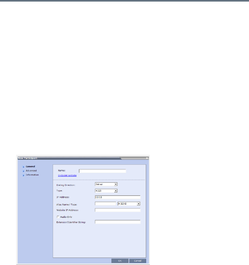
Conference and Participant Level Operations
Polycom, Inc. 388
Paste Participant As
The Paste Participant As command allows the MCU user to create a new participant using the copied
participant’s properties as a template. It automatically opens the Address Book - Participant Properties
dialog box allowing the MCU user to modify the participant’s properties effectively creating a new participant.
When the OK button in the Participant Properties dialog box is clicked, the new participant is connected
to the selected conference.
To paste a participant as a new participant:
1In the Conferences List pane, click the conference into which you want to paste the copied/cut
participant.
Right-click in the Participants List pane of the selected conference, and select Paste Participant As
or
If you are using the RMX Manager and you want to paste the participant to a conference on another
MCU:
aIn the MCUs list pane, click the MCU hosting the conference into which you wish to add the
participant.
bIn the Conferences list pane, click the conference into which you want to paste the copied/cut
participant.
cRight-click the Participants List pane, and select Paste Participant As.
The Address Book - Participant Properties dialog box is displayed.
2Modify the participant information as required. For more information, see Address Book.
Optional. If not already in the Address Book, both the copied/cut participant and the new one can be
added to the Address Book.
3Click OK to connect the new participant to the selected conference.

Conference and Participant Level Operations
Polycom, Inc. 389
Moving Participants Between Conferences
The Collaboration Server User can move participants between ongoing conferences, including an Operator
conference, and from the Entry Queue to the destination conference if help is required.
When moving between conferences or when a participant is moved from an Entry Queue to a conference
by the Collaboration Server user (after failure to enter the correct destination ID or conference password),
the IVR messages and slide display are skipped.
Move Guidelines
●Move is available only between CP conferences (meaning, not between Video Switching
conferences).
●Move between conferences can be performed without an active Operator conference.
●When moving the conference chairperson from one conference to another, the source conference
will automatically end if the Auto Terminate When Chairperson Exits option is enabled, and that
participant is the only conference chairperson.
●When moving the Operator to any conference (following assistance request), the IVR messages and
slide display are skipped.
●Participants cannot be moved from a Telepresence conference.
●Participants cannot be moved from LPR-enabled conferences to non-LPR conferences. Move from
non-LPR conferences to LPR-enabled conferences is possible.
●Move between encrypted and non-encrypted conferences depends on the
ALLOW_NON_ENCRYPT_PARTY_IN_ENCRYPT_CONF flag setting, as described in the following
table:
●When moving dial-out participants who are disconnected to another conference, the system
automatically dials out to connect them to the destination conference.
●Cascaded links cannot be moved between conferences.
Participant Move Capabilities vs. ALLOW_NON_ENCRYPT_PARTY_IN_ENCRYPT_CONF flag setting
Flag Setting
Source Conference/EQ
Encrypted
Destination
Conference Encrypted Move Enabled?
NO Yes Yes Yes
NO Yes No Yes
NO No Yes No
NO No No Yes
YES Yes Yes Yes
YES Yes No Yes
YES No Yes Yes
YES No No Yes
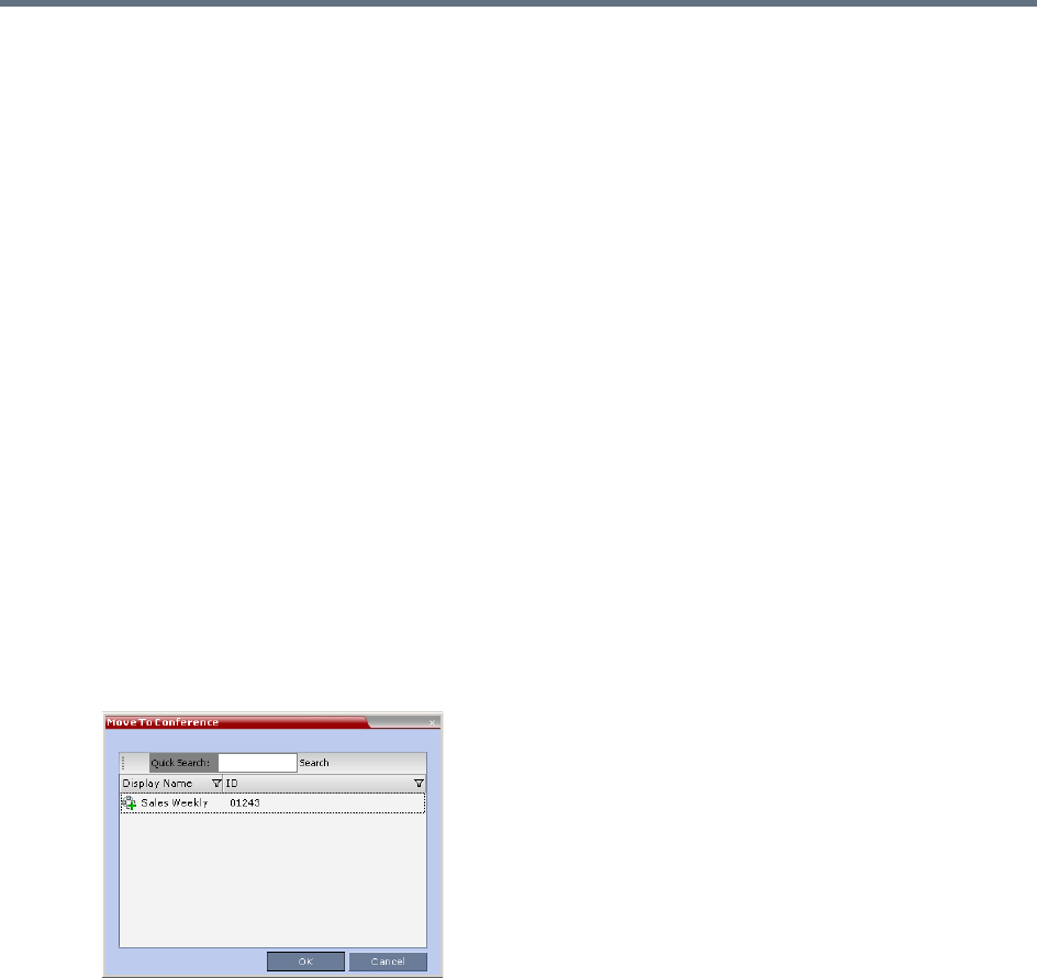
Conference and Participant Level Operations
Polycom, Inc. 390
●Participants cannot be moved to a conference if the move will cause the number of participants to
exceed the maximum number of participants allowed for the destination conference.
Moving Participants Options
Collaboration Server users can assist participants by performing the following operations:
●Move a participant to an Operator conference (Attend a participant).
●Move a participant to its Home (destination) conference.
●Move participant from one ongoing conference to another
A move can be performed using the following methods:
●Using the participant right-click menu
●Using drag and drop
To move a participant from the ongoing conference using the right-click menu options:
1In the Conference List pane, click the conference where there are participants waiting for
Operator’s Assistance to display the list of participants.
2In the Participants list, right-click the icon of the participant to be moved, and select one of the
following options:
Move to Operator Conference - to move the participant to the Operator conference.
Move to Conference - to move the participant to any ongoing conference.
When selected, the Move to Conference dialog box opens, letting you select the name of the
destination conference.
Back to Home Conference - if the participant was moved to another conference or to the
Operator conference, this options moves the participant back to its source conference.
This option is not available if the participant was moved from an Entry Queue to an Operator
conference or the destination conference.
Moving a Participant Interactively
You can drag and drop a participant from an Entry Queue or an ongoing conference to an Operator or
destination (Home) conference.
1Display the participants list of the Entry Queue or the source conference by clicking its entry in the
Conferences list.
2In the Participants list, drag the icon of the participant to the Conferences List pane, and drop it on
the Operator Conference icon or another ongoing conference.
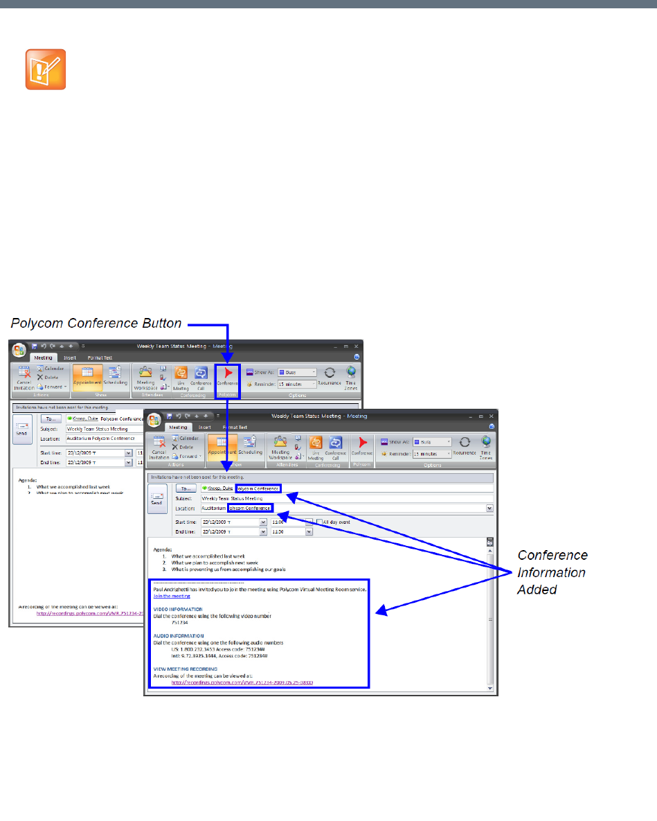
Polycom®, Inc. 391
Polycom Conferencing for Microsoft
Outlook®
Polycom Conferencing for Microsoft Outlook is an add-in that enables users to easily organize and invite
attendees to Video Enabled meetings via Microsoft Outlook®.
Polycom Conferencing for Microsoft Outlook is implemented by installing the Polycom Conferencing Add-in
for Microsoft Outlook on Microsoft Outlook® e-mail clients. It enables meetings to be scheduled with video
endpoints from within Outlook. The add-in also adds a Polycom Conference button in the Meeting tab of the
Microsoft Outlook e-mail client ribbon.
The meeting organizer clicks the Polycom Conference button to add Conference Information to the meeting
invitation.
Attendees call the meeting at the scheduled Start Time using the link or the dial-in number provided in the
meeting invitation.
Polycom Conferencing for Microsoft Outlook is supported in AVC CP Conferencing Mode only
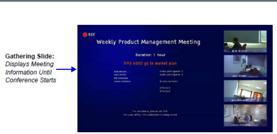
Polycom Conferencing for Microsoft Outlook®
Polycom®, Inc. 392
A Gathering Slide is displayed to connected participants until the conference starts.
The Gathering Slide displays live video along with information taken from the meeting invitation such as the
subject, meeting organizer, duration, dial-in numbers etc. At the end of the Gathering Phase, the conference
layout is displayed.
For more information see Video Preview (AVC Participants Only).
Setting up the Calendaring Solution
The following steps are performed to set up the Calendaring solution:
aThe administrator installs the Polycom Conferencing Add-in for Microsoft for Microsoft Outlook
e-mail clients. For more information, see the Polycom Unified Communications Deployment
Guide for Microsoft Environments.
bThe administrator creates an Microsoft Outlook e-mail-account for the Collaboration Server.
If included in the solution, Polycom RealPresence DMA system and calendaring-enabled
endpoints share this e-mail account. For more information, see the Polycom Unified
Communications Deployment Guide for Microsoft Environments.
cThe administrator configures the Collaboration Server for Calendaring using the Exchange
Integration Configuration dialog box, providing it with the Microsoft Exchange Server Name, User
Name and Password and optional Primary SMTP Mail box information needed to access the
e-mail account.
To configure the Collaboration Server’s Exchange Integration Configuration:
1On the Collaboration Server menu, click Setup > Exchange Integration Configuration.
The Exchange Integration Configuration dialog box is displayed.
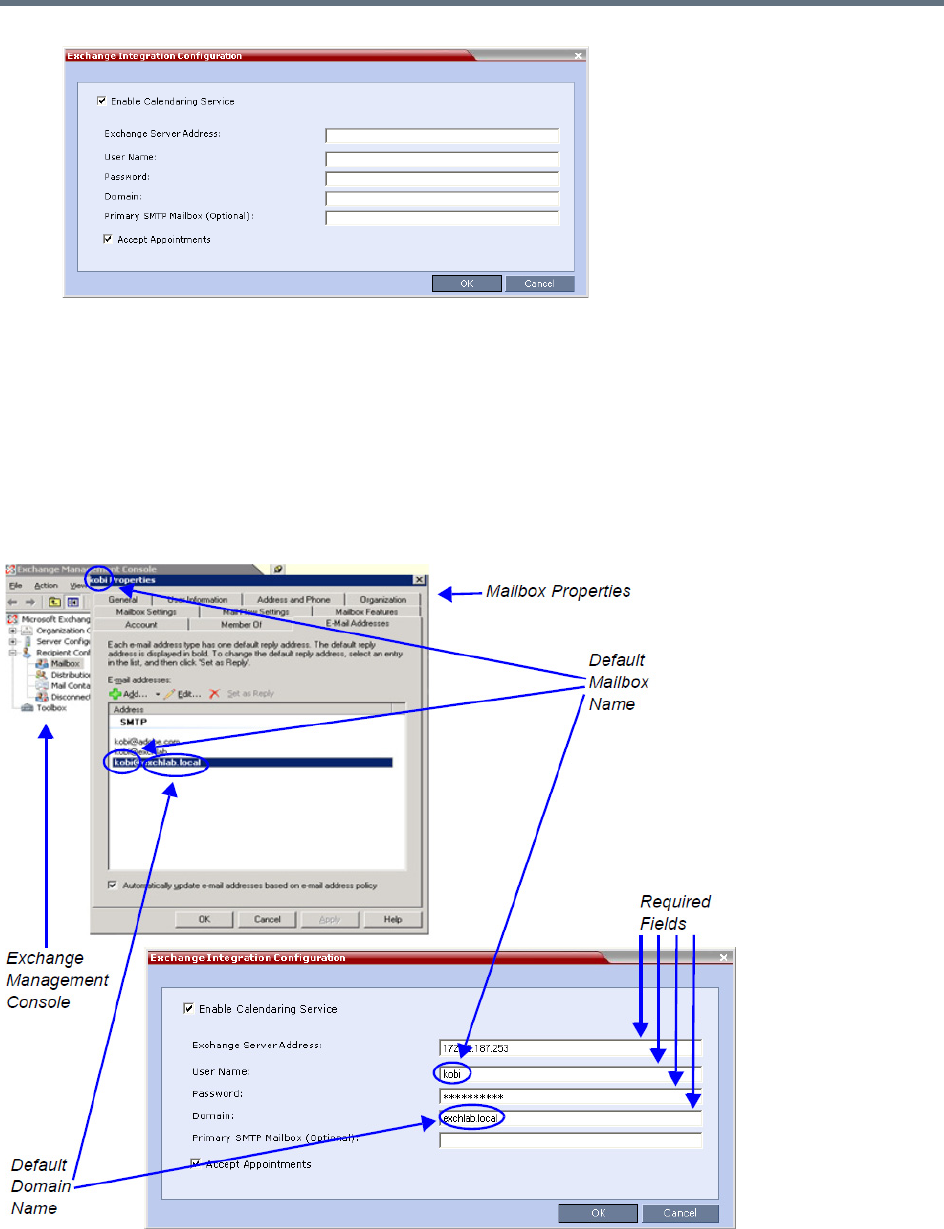
Polycom Conferencing for Microsoft Outlook®
Polycom®, Inc. 393
There are three options that can be used to configure the Exchange Integration Configuration. The
option you choose will depend on the configuration of the mailbox in the Exchange Server and the
configuration of the Exchange Server itself.
Option 1 - Use this option if the Exchange Server settings have been left at their default values.
Option 2 - Use this option if the Primary SMTP Mailbox is not the default mailbox.
Option 3 - Use this option if the Exchange Server settings have been modified by the
administrator.
Option 1 - Using default Exchange Server settings
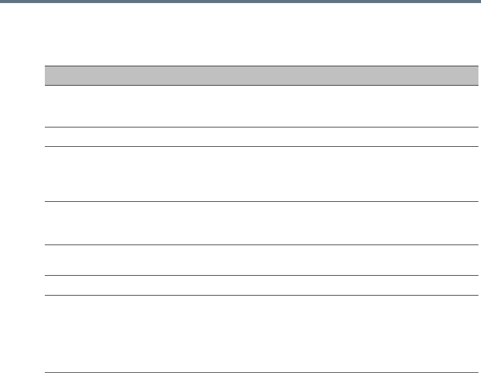
Polycom Conferencing for Microsoft Outlook®
Polycom®, Inc. 394
aDefine the following fields:
bClick OK.
Exchange Integration Configuration - Option 1
Field Description
Enable Calendaring Service Select or clear this check box to enable or disable the Calendaring
Service using the Polycom Add-in for Microsoft Outlook. When this
check box is cleared all fields in the dialog box are disabled.
Exchange Server Address Enter the IP address of the Exchange Server.
User Name Enter the User Name of the Collaboration Server, as registered in
the Microsoft Exchange Server, that the Collaboration Server uses
to login to its e-mail account.
Field length: Up to 80 characters.
Password Enter the Password the Collaboration Server uses to login to its
e-mail account as registered in the Microsoft Exchange Server.
Field length: Up to 80 characters.
Domain Enter the name of the network domain where the Collaboration
Server is installed as defined in the Microsoft Exchange Server.
Primary SMTP Mailbox (Optional) This field is left empty.
Accept Appointments Select this check box to enable the Collaboration Server to send
replies to meeting invitations.
Clear this check box when the Collaboration Server is part of a
Unified Conferencing solution that includes a RealPresence DMA
system, as the RealPresence DMA system will send a reply to the
meeting invitation.
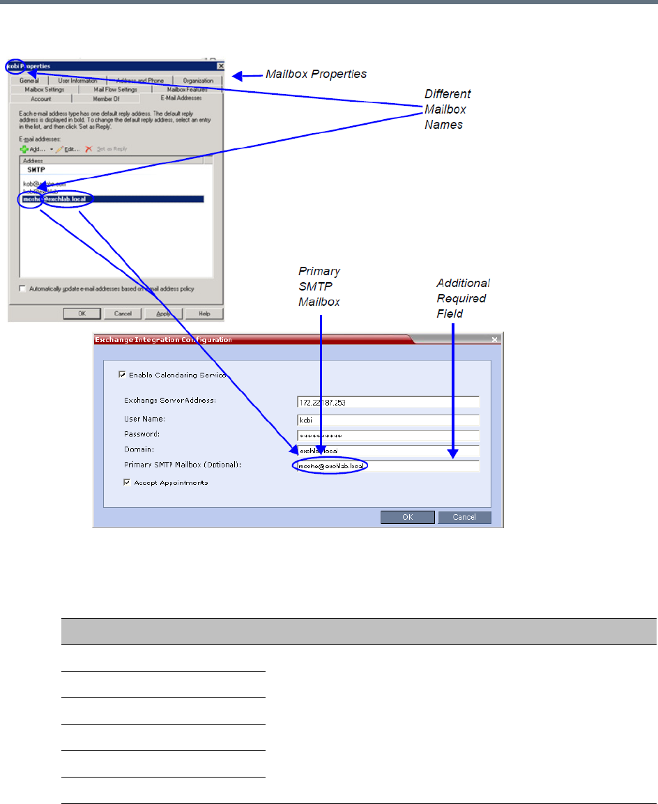
Polycom Conferencing for Microsoft Outlook®
Polycom®, Inc. 395
Option 2 - Using an alternate Primary SMTP Mailbox
aDefine the following fields:
Exchange Integration Configuration - Option 2
Field Description
Enable Calendaring Service
These fields are defined as for Option 1 above.
Exchange Server Address
User Name
Password
Domain
Accept Appointments
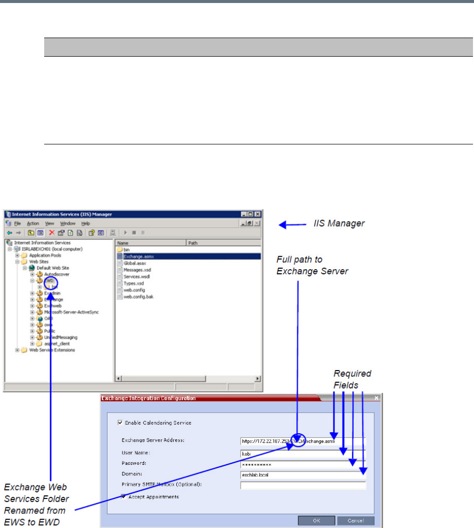
Polycom Conferencing for Microsoft Outlook®
Polycom®, Inc. 396
bClick OK.
Option 3 - Using modified Exchange Server settings
Primary SMTP Mailbox (Optional) Enter the name of the SMTP Mailbox in the Microsoft Exchange
Server to be monitored by the Collaboration Server.
Note: Although several mailboxes can be assigned to each user in
the Microsoft Exchange Server, only the Primary SMTP Mailbox is
monitored. The Primary SMTP Mailbox name does not have to
contain either the Collaboration Server’s User Name or Domain
name.
Exchange Integration Configuration - Option 2
Field Description
Polycom Conferencing for Microsoft Outlook®
Polycom®, Inc. 397
aDefine the following fields:
bClick the OK button.
If applicable, RealPresence Capture Server or RSS systems, VMC, RealPresence DMA system, and
calendaring-enabled endpoints are configured with the Exchange Server Name, User Names and
Passwords needed to access their accounts.
For more information see the Polycom Unified Communications Deployment Guide for Microsoft
Environments.
The administrator configures the Collaboration Server to have a default Ad-hoc Entry Queue service
enabled.If ISDN/PSTN participants are included, up to two ISDN/PSTN dial-in numbers must be
configured for the Ad Hoc Entry Queue.
For more information see Defining a New Entry Queue.
Calendaring Guidelines
●The Collaboration Server must have its MCU prefix registered in the gatekeeper.
For more information see Modifying the Default IP Network Service.
●The Collaboration Server must be configured as a Static Route.
For more information see Modifying the Default IP Network Service.
Exchange Integration Configuration - Option 3
Field Description
Exchange Server Address If Exchange Server settings have been modified, enter the full path
to the Microsoft Exchange Server where the Collaboration Server’s
Microsoft Outlook e-mail account is registered, for example if the
EWS folder has been renamed EWD:
https://labexch01/EWD/Exchange.asmx
Note: If a server name is entered, the Collaboration Server and the
Microsoft Exchange Server must be registered to the same
Domain. (The Domain name entered in this dialog box must match
the Local Domain Name entry in the Management Network - DNS
Properties dialog box.)
For more information see Modifying the Default IP Network Service.
Field length: Up to 80 characters.
Enable Calendaring Service
These fields are defined as for Option 1 above.
User Name
Password
Domain
Primary SMTP Mailbox (Optional)
Accept Appointments

Polycom Conferencing for Microsoft Outlook®
Polycom®, Inc. 398
●The Collaboration Server’s Default Entry Queue must be configured as an Ad Hoc Entry Queue and
must be designated as the Transit Entry Queue.
For more information see the Entry Queues.
●The meeting organizer can enable recording and/or streaming of the meeting.
●If meeting is to be recorded, the Ad Hoc Entry Queue must have recording enabled in its Profile.
For more information see Defining AVC CP Conferencing Profiles.
●Meetings can be single instance or have multiple occurrences.
●Attendees that do not have video devices may be invited to the meeting.
●Attendees using e-mail applications that use the iCalendar format may be invited to meetings via the
Calendaring Service.
●Meeting invitations sent by Polycom Conferencing for Microsoft Outlook can be in a different
language to the Collaboration Server Web Client. The following languages are supported:
English
French
German
International Spanish
Korean
Japanese
Simplified Chinese
●Collaboration Server resource management is the responsibility of the system administrator:
Conferences initiated by Polycom Conferencing for Microsoft Outlook are ad hoc and therefore
resources are not reserved in advance.
Polycom Conferencing for Microsoft Outlook Add-in assumes that sufficient resources are
available and does not check resource availability. Sufficient resources are therefore not
guaranteed.
A meeting invitation that is automatically accepted by the Collaboration Server is not guaranteed
availability of resources.
If the Collaboration Server runs out of resources, attendees will not be able to connect to their
conferences.
●By using RealPresence DMA system to load-balance resources between several Collaboration
Servers, resource capacity can be increased, alleviating resource availability problems.
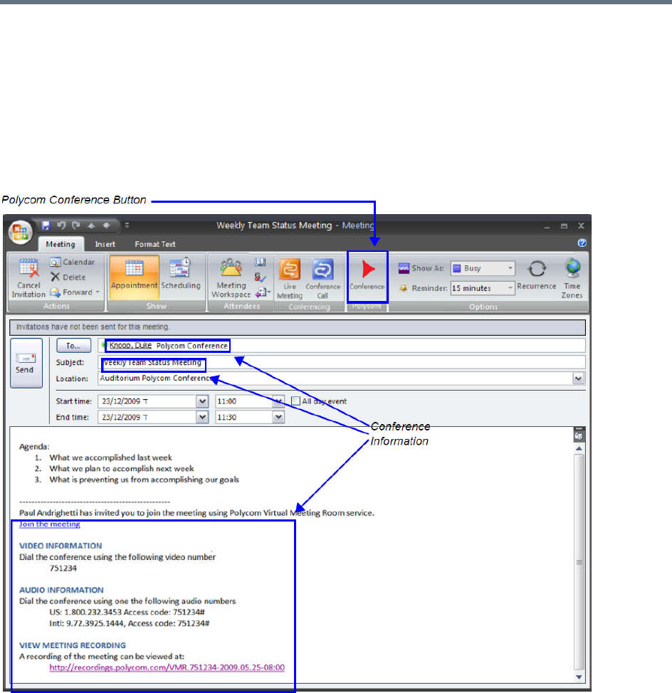
Polycom Conferencing for Microsoft Outlook®
Polycom®, Inc. 399
Creating and Connecting to a Conference
Creating a Conference
Meetings are organized using the Microsoft Outlook client in the normal manner.
If the meeting organizer decides that video participants are to be included in a multipoint video conference,
he/she clicks the Polycom Conference button. Conference Information such as the Meeting ID and
connection information is automatically added to the existing appointment information.
The meeting organizer can add a meeting agenda or personal text to the invitation before it is sent. The
meeting organizer can update or cancel the video enabled meeting in the same manner as for any other
meeting.
When the meeting organizer sends the meeting invitation a meeting record is saved in the Microsoft
Exchange Server, the RealPresence Collaboration Server, RealPresence DMA system, RealPresence
Capture Server or RSS systems, and calendaring-enabled endpoints.
RealPresence Collaboration Servers, RealPresence DMA system, and calendaring-enabled endpoints poll
the Microsoft Exchange Server to retrieve new meeting records and updates to existing meeting records.

Polycom Conferencing for Microsoft Outlook®
Polycom®, Inc. 400
Microsoft Outlook Field Usage table below summarizes the Collaboration Server’s usage of Microsoft
Outlook data fields included in the meeting invitation.
Connecting to a Conference
Participants can connect to the conference in the following ways:
●Participants with Polycom CMA/RealPresence Desktop™ or a Microsoft Office Communicator client
running on their PCs can click on a link in the meeting invitation to connect to the meeting.
Microsoft Outlook Field Usage
Microsoft
Outlook Field
Usage by the Collaboration Server / RealPresence DMAsystem
Conference / Meeting Room Gathering Slide
Subject Display Name of Conference / Meeting
Room.
Meeting Name.
Start/End Time Used to calculate the Conference’s Duration.
Record Enable Recording in the Conference or
Meeting Room Profile.
Display Recording option.
Video Access
Number
Comprised of: <MCU Prefix in
Gatekeeper> <Conference
Numeric ID>.
Note: It is important that MCU Prefix in
Gatekeeper field in the Collaboration
Server’s IP Network Service -
Gatekeeper tab and the Dial-in prefix
field in the Polycom Conferencing
Add-in for Microsoft Outlook - Video
Network tab contain the same prefix
information.
If Recording and Streaming are enabled
in the Conference Profile, this number
is used as part of the recording file
name.
Displayed as the IP dial in number
in the Access Number section of
the Gathering Slide.
Audio Access
Number
ISDN/PSTN dial-in number.
Up to two numbers are supported.
Displayed as the ISDN/PSTN
dial-in number in the Access
Number section of the Gathering
Slide.
Streaming
recording link
Enables the recording of the
conference to the Polycom
RealPresence Capture Server or
RSS systems using the recording link.
Enables streaming of the recording of
the conference from the Polycom
RealPresence Capture Server or
RSS systems.
If recording is enabled, a REC
indicator is displayed in the top left
corner of the slide.

Polycom Conferencing for Microsoft Outlook®
Polycom®, Inc. 401
●Participants with a HDX or a room system will receive a prompt from the endpoint’s calendaring
system along with a button that can be clicked in order to connect.
Participants with endpoints that are not calendaring-enabled can connect to the meeting by dialing
the meeting number manually.
●Participants outside the office or using PSTN or mobile phones, can use the dial in number in the
meeting invitation to manually dial in to the meeting.
Collaboration Server Standalone Deployment
When using a single Collaboration Server in a standalone deployment, connection is via an Ad Hoc Entry
Queue. The meeting is started when the first participant connects to the Collaboration Server.
When the first participant connects, a conference is created and named according to the information
contained in the dial string. Subsequent participants connecting with the same dial string are routed from
the Ad Hoc Entry Queue to the conference.
After the conference has been created the Conference Name, Organizer, Time, Duration and Password (if
enabled) are retrieved from the conference parameters for display during the Gathering Phase.
Collaboration Server and Polycom RealPresence DMA System Deployment
In a RealPresence DMA system deployment a Virtual Meeting Room is activated when the first participant
connects to the RealPresence DMA system. The RealPresence DMA system receives the dial string to
activate a Virtual Meeting Room on the Collaboration Server.
The RealPresence DMA system uses the Meeting ID contained in the dial-in string to access meeting
information stored in the Exchange Server database.
When the meeting information is found on the Exchange Server, the Conference Name, Organizer, Time,
Duration and Password (if enabled) are retrieved from the Exchange Server database for display during the
Gathering Phase.
Polycom Solution Support
Polycom Implementation and Maintenance services provide support for Polycom solution components only.
Additional services for supported third-party Unified Communications (UC) environments integrated with
Polycom solutions are available from Polycom Global Services and its certified Partners. These additional
services will help customers successfully design, deploy, optimize and manage Polycom visual
communications within their UC environments.
Professional Services for Microsoft Integration is mandatory for Polycom Conferencing for Microsoft Outlook
and Microsoft Office Communications Server integrations. For additional information and details please see
http://www.polycom.com/services/professional_services/index.html or contact your local Polycom
representative.
If enabled, automatically generated passwords are ignored.
For more information see Automatic Password Generation Flags.
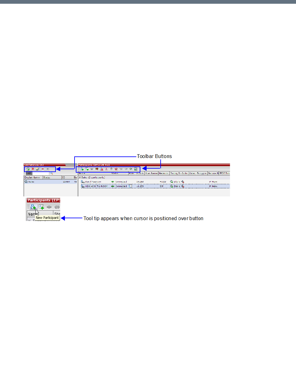
Polycom®, Inc. 402
Conference and Participant Monitoring
You can monitor ongoing conferences and perform various operations while conferences are running.
Three levels of monitoring are available with the Collaboration Server:
●General Monitoring - You can monitor the general status of all ongoing conferences and their
participants in the main window.
●Conference Level Monitoring - You can view additional information regarding a specific conference
and modify its parameters if required, using the Conference Properties option.
●Participant Level Monitoring - You can view detailed information on the participant's status, using the
Participant Properties option.
General Monitoring
Users can monitor a conference or keep track of its participants and progress.
All monitoring and operations procedures performed during ongoing conferences can be performed by
either of following two methods:
●Using the buttons in the toolbars.
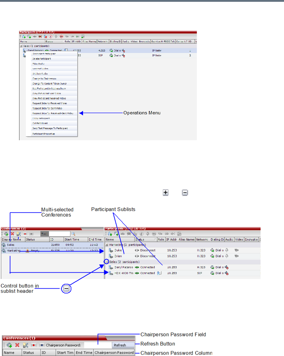
Conference and Participant Monitoring
Polycom®, Inc. 403
●Right-clicking an entity in the Conferences or Participants pane and selecting an operation from the
menu.
Multi-Selection
Using multiple selection, you can monitor and perform simultaneous operations on multiple participants in
multiple conferences.
The selected conferences are displayed as sub-lists in the Participants list pane.
The sub-lists can be expanded and collapsed by clicking the and sublist control buttons that appear
next to the conference name in the sub-list headings.
Using the Chairperson Password for Filtering
If you are logged in as a chairperson, the Chairperson Password field is displayed. It enables you to
search for, and display a list of, ongoing conferences for which you have the password.
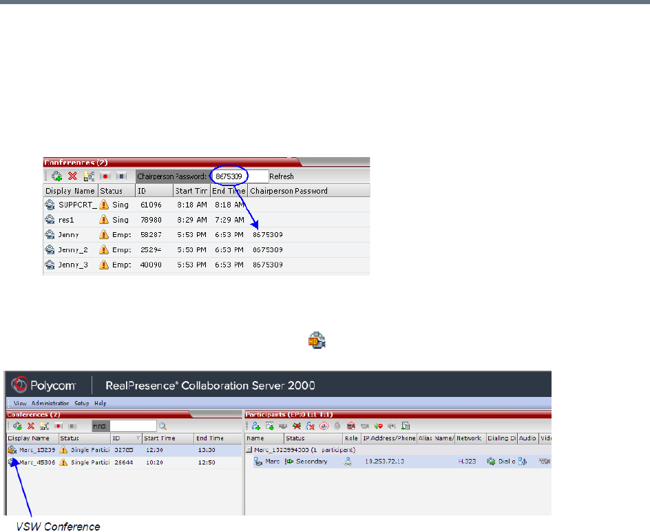
Conference and Participant Monitoring
Polycom®, Inc. 404
To search for an ongoing conference by Chairperson Password:
1Click in the Chairperson Password field.
2Enter the password to be searched for.
3Click the Refresh button.
The Conferences list is refreshed and ongoing conferences with the requested password are
displayed.
You can also click the blinking Participant Alerts indication bar to view participants that require attention. For
more information, see System and Participant Alerts.
Video Switching conferences appear with the HD ( ) icon in the conferences list to differentiate between
CP and VSW conferences.
Monitoring is done in the same way as for CP conferences.
Conference Level Monitoring
In addition to the general conference information that is displayed in the Conference list pane, you can view
the details of the conference’s current status and setup parameters, using the Conference Properties dialog
box.
The tabs displayed in the Conference Properties dialog boxes are dependent on the Conferencing Mode,
the participant authorization, and the Card Configuration Mode of the Collaboration Server (for Collaboration
Server 1500/2000/4000) — whether MPMx or MPMRx cards.
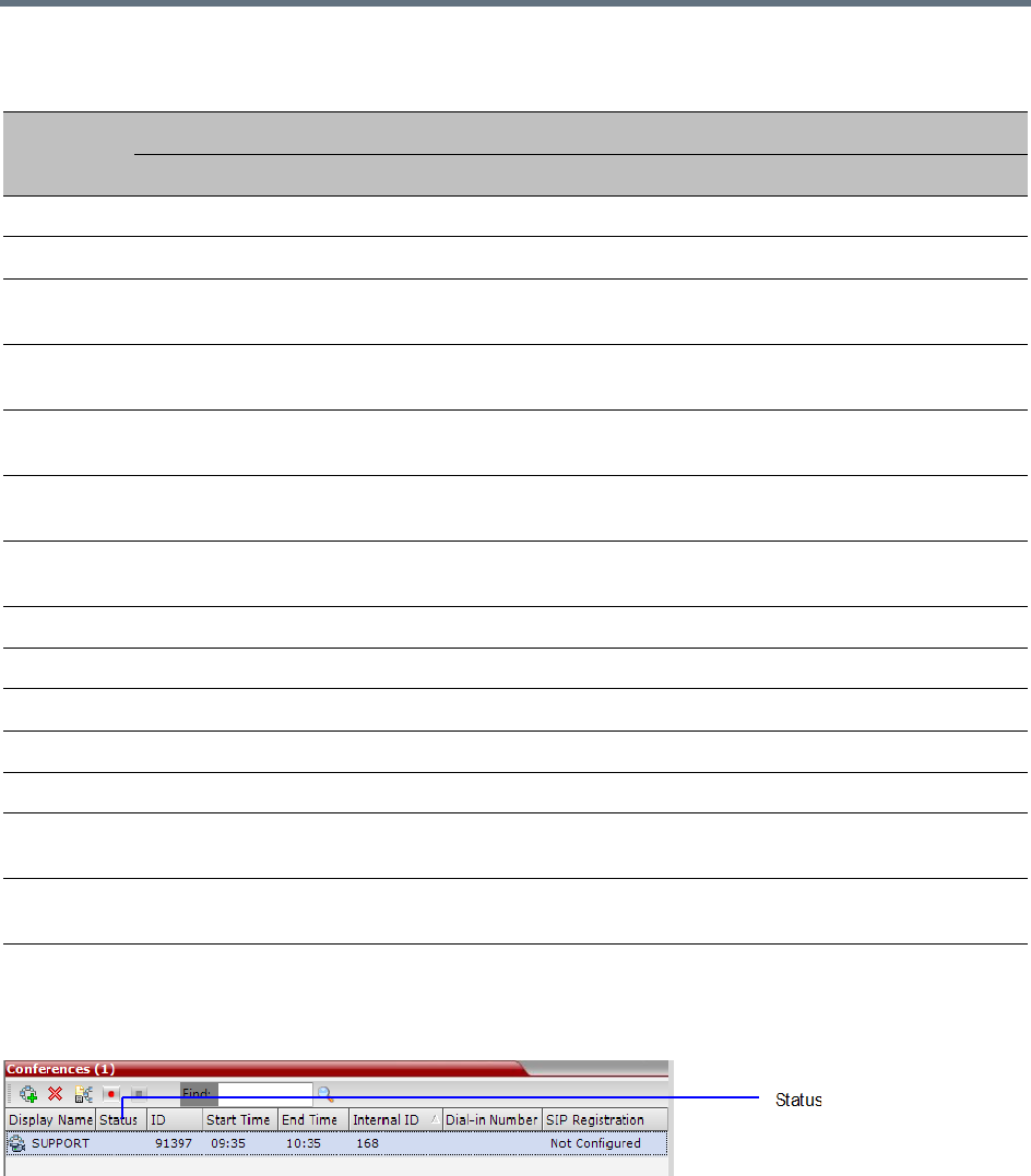
Conference and Participant Monitoring
Polycom®, Inc. 405
Monitoring the Conference in the Conference List Pane
The Conference List pane displays information about ongoing conferences.
No status indicator display in the Status column means that the conference is running without problems.
One or more of the status indicators may appear in the Status column.
Conference monitoring - Tab list per conferencing mode and user
Tab Name
Admin Chairperson Operator
CP SVC Mixed VSW CP SVC Mixed VSW CP SVC Mixed VSW
General
Advanced
Gathering
Settings
Video
Quality
Video
Settings
Audio
Settings
Customized
Polling
Skins
IVR
Information
Recording
Site Names
Message
Overlay
Network
Services
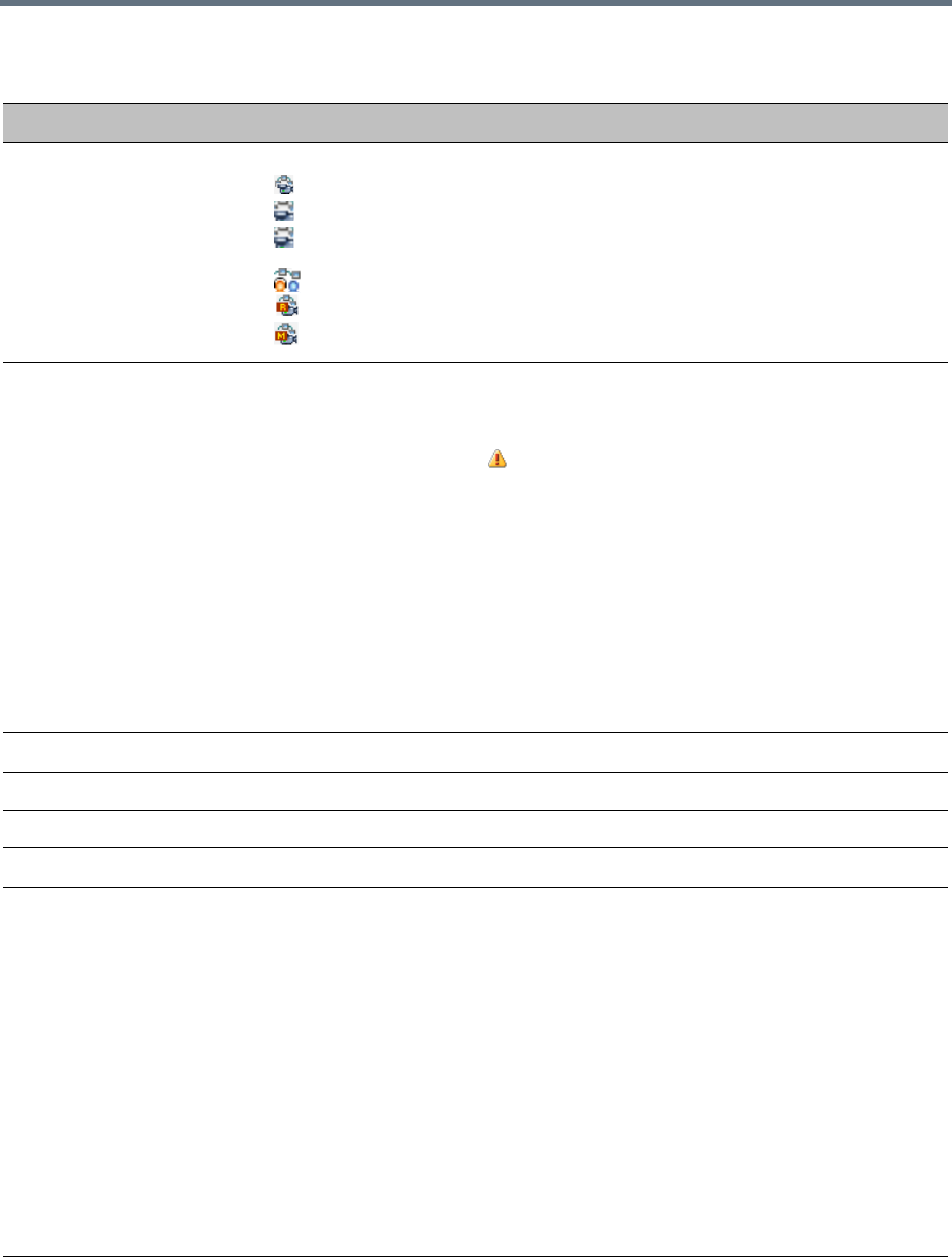
Conference and Participant Monitoring
Polycom®, Inc. 406
Conferences – Monitoring Information
Field Description
Display Name Displays conference name and type of conference:
• – AVC Conference running in CP mode.
• – AVC Conference running in Video Switching mode.
• – The AVC conference has been secured using the *71 DTMF code. For details,
see Secured Conference Monitoring (AVC CP Only).
• – AVC Operator Conference
• – Media Relay - SVC-based Conference.
• – Mixed CP and SVC Conference
Status Displays the status of the ongoing conference.
If there is no problem with the participant’s connection no indication is displayed.
If one of the following statuses occur, the appropriate indication is displayed,
proceeded by a warning icon ( ).
•Audio – There is a problem with the participant’s audio.
•Empty – No participants are connected.
• Faulty Connection – Participants are connected, but the connection is problematic.
• Not Full – Not all the defined participants are connected.
• Partially Connected – The connection process is not yet complete; the video
channel has not been connected.
• Single Participant – Only one participant is connected.
•Video – There is a problem with the participant’s video.
• Content Resource Deficiency – Content will not be sent to legacy endpoints.
• Awaiting Operator – A participant has requested operator assistance.
ID The Conference ID assigned to the conference.
Start Time Conference start time.
End Time The time the conference is expected to end.
Dial in Number(1) The Conference dial in number for ISDN/PSTN participants.
SIP Registration The status of registration with the SIP server:
• Not configured - Registration with the SIP Server was not enabled in the
Conference Profile assigned to this conferencing Entity.
In Multiple Networks configuration, If one service is not configured while others are
configured and registered, the status reflects the registration with the configured
Network Services. The registration status with each SIP Server can be viewed in
the Properties - Network Services dialog box of each conferencing entity.
•Failed - Registration with the SIP Server failed. This may be due to incorrect
definition of the SIP server in the IP Network Service, or the SIP server may be
down, or any other reason the affects the connection between the MCU or the SIP
Server to the network.
•Registered - The conferencing entity is registered with the SIP Server.
• Partially Registered - This status is available only in Multiple Networks
configuration, when the conferencing entity failed to register to all the required
Network Services if more than one Network Service was selected.

Conference and Participant Monitoring
Polycom®, Inc. 407
Additional information about the conference can be viewed when accessing the conference properties.
Viewing the Properties of CP and Mixed CP and SVC Conferences
To view the parameters of an ongoing CP conference:
1In the Conference list pane, double-click the conference, or right-click the conference and then click
Conference Properties.
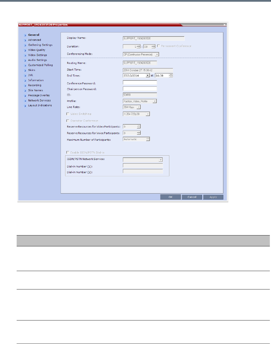
Conference and Participant Monitoring
Polycom®, Inc. 408
The Conference Properties - General dialog box with the General tab opens.
The following information is displayed in the General tab:
Conference Properties - General
Field Description
Display Name The Display Name is the conference name in native language and Unicode
character sets to be displayed in the Collaboration Server Web Client.
Note: This field is displayed in all tabs.
Duration The expected duration of the conference using the format HH:MM.
Note: This field is displayed in all tabs.
Permanent Conference Indicates whether the conference is set as a Permanent Conference, with no
pre-determined End Time. This conference continues until it is terminated by
an administrator, operator or chairperson.
Note: This field is displayed in all tabs.
Routing Name The ASCII name of the conference. It can be used by H.323 and SIP
participants for dialing in directly to the conference. It is used to register the
conference in the gatekeeper and the SIP server.

Conference and Participant Monitoring
Polycom®, Inc. 409
Conferencing Mode The conferencing mode set for the conference: CP, VSW, SVC Only, or CP
and SVC.
Start Time The time the conference started.
End Time The expected conference end time.
Note: This field is not shown when the conference is set as a Permanent
Conference.
Conference Password A numeric password for participants to access the conference.
Chairperson Password A numeric password used by participants to identify themselves as the
conference chairperson.
ID The conference ID.
Profile The name of the conference Profile from which conference parameters were
taken.
Line Rate The maximum transfer rate, in kilobytes per second (Kbps) of the call (video
and audio streams).
Video Switching When selected, the conference is running in a special conferencing mode
which implies that all participants must connect at the same line rate and the
video parameters are set according to the highest common parameters.
Participants with endpoints not supporting the video parameters (such as the
video protocol, resolution and frame rate) selected for the conference will
connect as secondary (audio only). If HD 1080p is selected for the conference,
endpoints that do not support HD 1080p resolution are connected as
Secondary (Audio Only) participants.
Video layout changes are not enabled during a conference.
Note: Video Switching conferencing mode is unavailable to ISDN participants.
For more information, see Video Switching (VSW) Conferencing.
Reserve Resources for
Video Participants
Displays the number of video participants for which the system reserved
resources.
Default: 0 participants.
Reserve Resources for
Audio Participants
Displays the number of audio participants for which the system reserved
resources.
Default: 0 participants.
Max Number of
Participants
Indicates the total number of participants that can be connected to the
conference. The Automatic setting indicates the maximum number of
participants that can be connected to the MCU according to resource
availability.
Enable ISDN/PSTN
Network Service
When selected, ISDN/PSTN participants can dial into the conference.
ISDN/PSTN Network
Service
When the Enable ISDN/PSTN Network Service is selected, displays the default
Network Service.
Conference Properties - General
Field Description
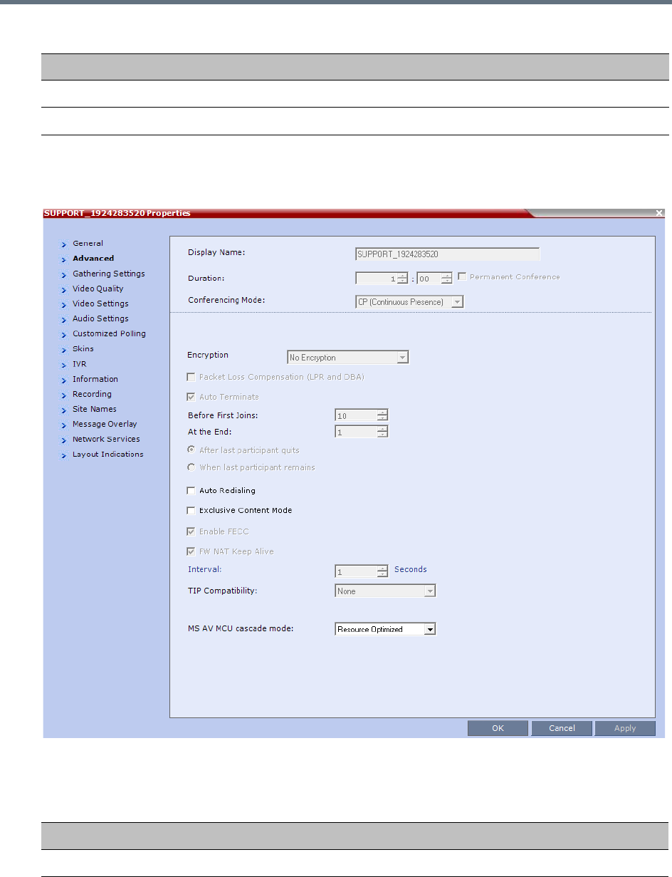
Conference and Participant Monitoring
Polycom®, Inc. 410
2Click the Advanced tab.
The Conference Properties - Advanced dialog box opens.
3The following information is displayed in the Advanced tab:
Dial-in Number (1) Displays the conference dial in number.
Dial-in Number (2) Displays the conference dial in number.
Conference Properties - Advanced Parameters
Field/Option Description
Encryption Indicates whether the conference is encrypted.
Conference Properties - General
Field Description
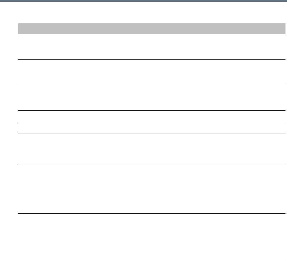
Conference and Participant Monitoring
Polycom®, Inc. 411
4Click the Gathering Settings tab.
The Conference Properties - Gathering Settings dialog box opens.
Packet Loss
Compensation (LPR and
DBA)
Indicates wether Packet Loss Compensation (LPR and DBA) is enabled for the
conference.
Auto Terminate When selected, indicates that the MCU will automatically terminate the
conference when Before First Joins, At the End-After Last Quits and At the
End - When Last Participant Remains parameters apply.
Auto Redialing Indicates whether dial-out participants are automatically (when selected) or
manually (when cleared) connected to the conference.
This option is disabled in mixed CP and SVC conferences.
Exclusive Content Mode When selected, Content is limited to one participant.
Enable FECC When selected, Far End Camera Control is enabled.
FW NAT Keep Alive When selected, sends a FW NAT Keep Alive message at specific Intervals for
the RTP, UDP and BFCP channels. The interval specifies how often a FW NAT
Keep Alive message is sent. For more information, see RealPresence
Collaboration Server (RMX) Network Port Usage.
TIP Compatibility Indicates the TIP Compatibility mode implemented for the conference, when
the environment implements the Collaboration Server and Cisco Telepresence
Systems (CTS) Integration solution.
•None
• Prefer TIP
For more information, see .
MS AV MCU cascade
mode
This field is part of the Microsoft Lync utility and defines the resource usage in
the cascading relationship between Polycom RealPresence Collaboration
Server and Microsoft Lync server.
Microsoft Lync is not supported by Collaboration Server (RMX) 18000-0.
For more information see Video Resource Requirement Selection in Lync 2013
AVMCU Cascade.
Conference Properties - Advanced Parameters
Field/Option Description
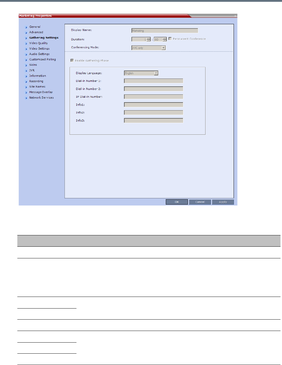
Conference and Participant Monitoring
Polycom®, Inc. 412
The following information is displayed:
Profile - Gathering Settings
Field/Options Description
Enable Gathering Indicates whether the Gathering Phase has been enabled.
Display Language Indicates the language of the Gathering Slide field headings.
Note: When working with the Polycom Conferencing Add-in for Microsoft Outlook,
the language selected should match the language selected for the conference in
the Polycom Conferencing Add-in for Microsoft Outlook to ensure that the
Gathering Phase slide displays correctly.
Access Number 1 Indicates the ISDN or PSTN number(s) to call to connect to the conference.
Note: The numbers entered must be verified as the actual Access Numbers.
Access Number 2
IP Dial-in Number
Info 1 Additional information to be displayed during the Gathering Phase.
Info 2
Info 3
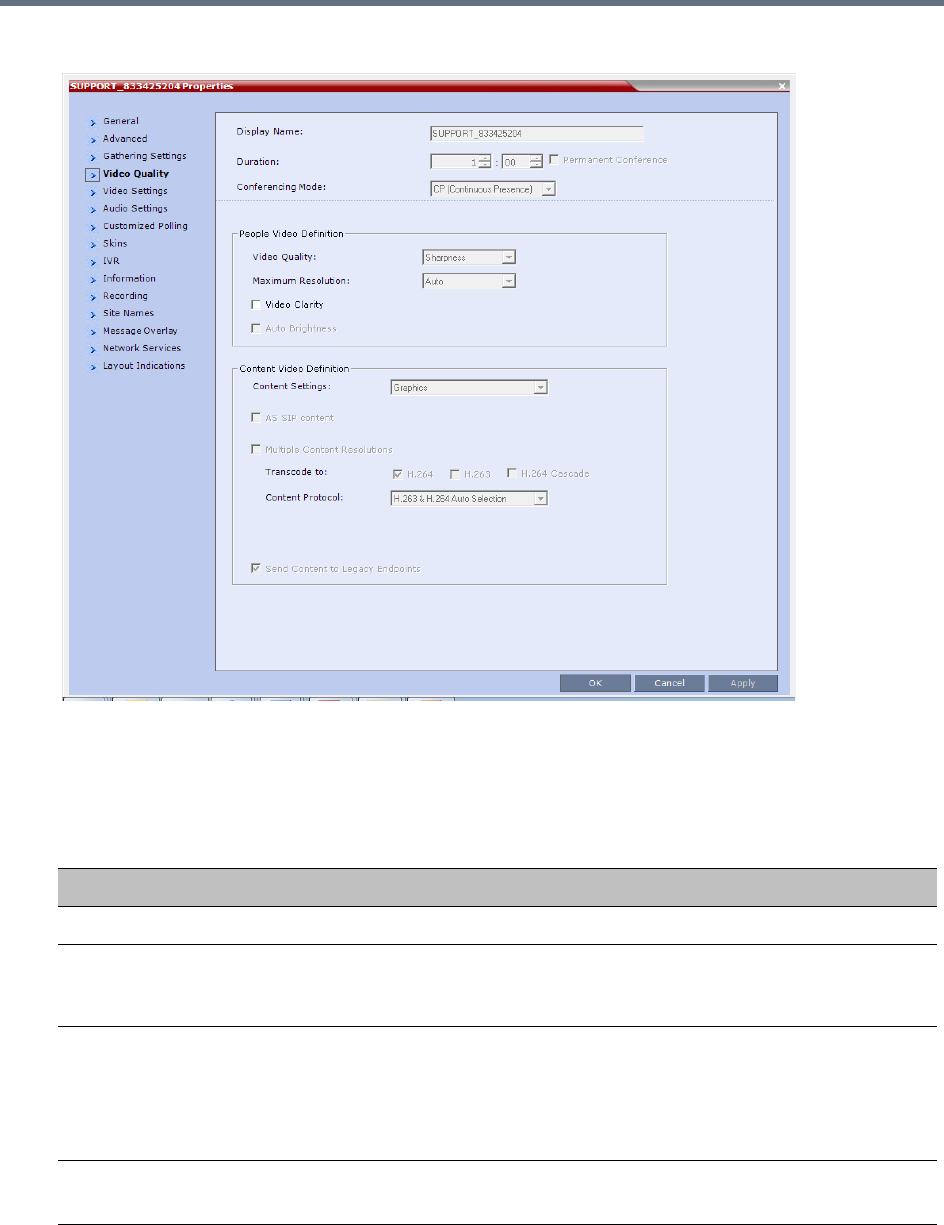
Conference and Participant Monitoring
Polycom®, Inc. 413
5Click the Video Quality tab.
The Conference Properties - Video Quality dialog box opens.
The following information is displayed:
Conference Properties - Video Quality Parameters
Field/Option Description
People Video Definition
Video Quality Indicates the resolution and frame rate that determine the video quality set for
the conference. Possible settings are: Motion or Sharpness. For more
information, see Video Resolutions in AVC CP Conferencing.
Maximum Resolution Indicates the Maximum Resolution setting for the conference.
Auto (default) - indicates that the Maximum Resolution is selected in the
Resolution Configuration dialog box.
The Maximum Resolution settings for conferences and participants cannot be
changed during an ongoing conference.
Video Clarity Indicates if Video Clarity is enabled for the conference.
Video Clarity is not support by Collaboration Server (RMX) 1800-0.
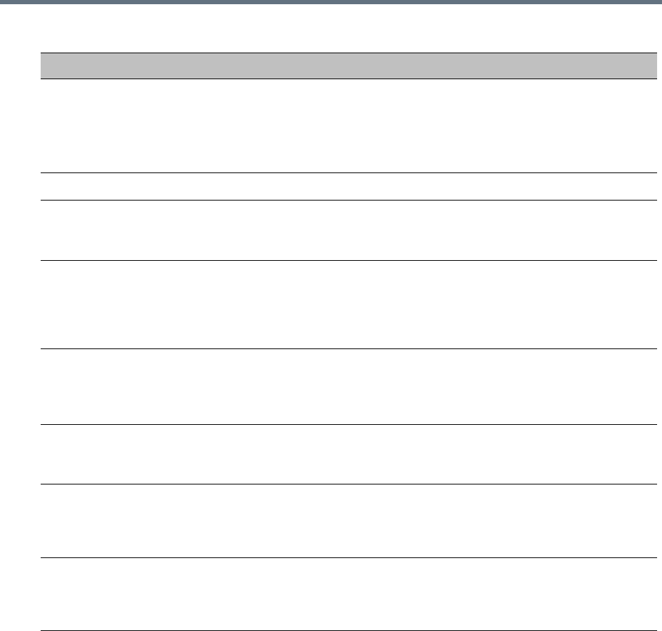
Conference and Participant Monitoring
Polycom®, Inc. 414
6Click the Video Settings tab to list the video parameters.
Auto Brightness Indicates if Auto Brightness is selected for the conference.
Note: When Auto Brightness is enabled, color changes may be observed in
computer-based VGA Content sent by HDX endpoints through the People video
channel.
Auto Brightness is not support by Collaboration Server (RMX) 1800-0.
Content Video Definition
AS-SIP When selected, content is shared using the Multiple Resolutions mode and is
not supported in any other Content sharing mode.
For more information, see Enabling AS-SIP Content.
Multiple Content
Resolutions
Indicates if Multiple Content Resolutions mode for content sharing is enabled. In
this mode, content is shared in multiple streams, one for each video protocol:
H.263 and H.264. This allows endpoints with different protocols to connect and
disconnect without having to restart Content sharing in the middle of a
conference. For more information, see Multiple Content Resolutions.
Content Settings Indicates the Content channel resolution set for the conference. Possible
resolutions are Graphics (default), Hi-res Graphics, Live Video, and
Customized Content Rate.
For more information, see Content Settings.
Content Protocol Indicates the Content Protocol used for content sharing in Highest Common
Content Sharing Mode.
For more information, see MCU Usage Modes of Content Protocols.
Content Resolution Indicates the Content Resolution and frame rate according to the selected
Content Sharing Mode (Highest common Content or Multiple Resolution
Contents) and the video protocol. For more information, see H.264 Cascade
Optimized.
Send Content to Legacy
Endpoints
(CP only)
Indicates if the Send Content to Legacy Endpoints is enabled. If enabled,
Content can be sent to H.323/SIP/ISDN endpoints that do not support H.239
Content (legacy endpoints) over the video (people) channel. For more
information see Sending Content to Legacy Endpoints.
Conference Properties - Video Quality Parameters
Field/Option Description
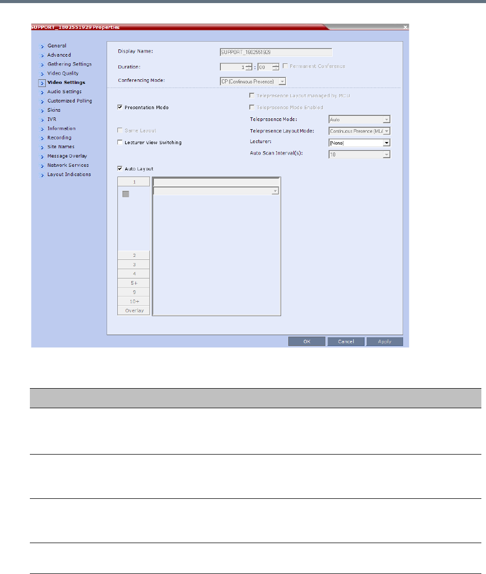
Conference and Participant Monitoring
Polycom®, Inc. 415
Conference Properties - Video Settings Parameters
Field Description
Presentation Mode When checked, indicates that the Presentations Mode is active.
This option is disabled in a mixed CP and SVC conference.
For more information, see Supplemental Conferencing Features.
Lecturer View
Switching
When checked, the Lecturer View Switching enables automatic random
switching between the conference participants in the lecturer video window.
This option is disabled in a mixed CP and SVC conference.
Same Layout When checked, forces the selected layout on all conference participants, and the
Personal Layout option is disabled.
This option is disabled in a mixed CP and SVC conference.
Auto Layout When enabled, the system automatically selects the conference layout based on
the number of participants in the conference.
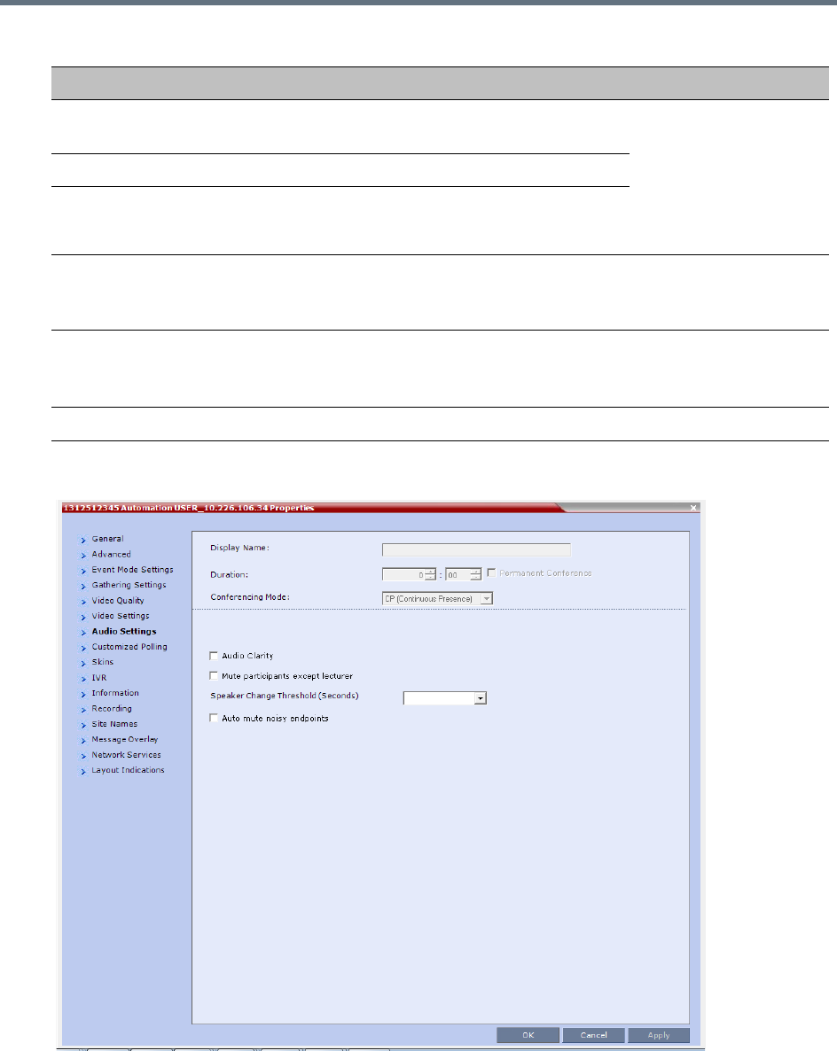
Conference and Participant Monitoring
Polycom®, Inc. 416
7Click the Audio Settings tab to view the audio setting for the conference.
8If needed, you can enable or disable the Mute participants except lecturer setting.
Telepresence Mode
Enabled
Indicates if the conference is running in Telepresence
Mode.
These fields are enabled
if the Collaboration
Server has a
Telepresence license
installed.
See Defining New
Profiles.
Telepresence Mode Indicates the Telepresence Mode.
Telepresence Layout
Mode
Indicates the layout of the Telepresence Mode.
Lecturer Indicates the name of the lecturer (if one is selected). Selecting a lecturer enables
the Lecture Mode.
This option is disabled in a mixed CP and SVC conference.
Auto Scan Interval(s) The time interval, 10 - 300 seconds, that Auto Scan uses to cycle the display of
participants that are not in the conference layout in the selected cell.
This option is disabled in a mixed CP and SVC conference.
Video Layouts Indicates the currently selected video layout.
Conference Properties - Video Settings Parameters
Field Description
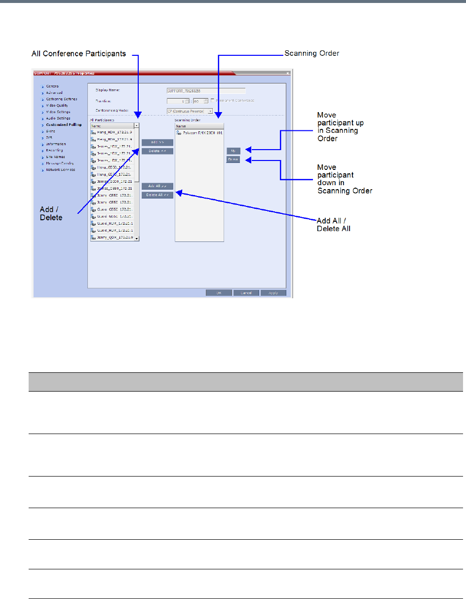
Conference and Participant Monitoring
Polycom®, Inc. 417
9 CP Only Conferences: Click the Customized Polling tab to view and modify the customized
polling for the conference.
All conference participants are listed in the left pane (All Participants) whereas the participants to be
displayed in the Auto Scan enabled cell are listed in the right pane (Scanning Order).
The dialog box buttons are summarized in the table below.
Customized Polling - Buttons
Button Description
Add Select a participant and click this button to add a the participant to the list of
participants to be Auto Scanned.
The participants name is removed from the All Participants pane.
Delete Select a participant and click this button to delete the participant from the list of
participants to be Auto Scanned.
The participants name is moved back to the All Participants pane.
Add All Add all participants to the list of participants to be Auto Scanned.
All participants’ names are removed from the All Participants pane.
Delete All Delete all participant from the list of participants to be Auto Scanned.
All participants’ names are moved back to the All Participants pane.
Up Select a participant and click this button to move the participant up in the Scanning
Order.
Down Select a participant and click this button to move the participant down in the
Scanning Order.
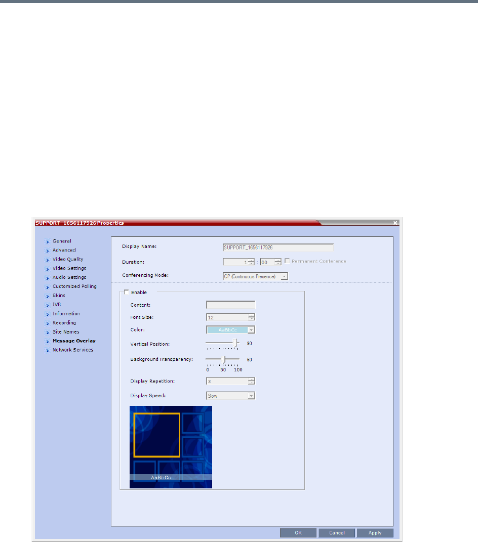
Conference and Participant Monitoring
Polycom®, Inc. 418
10 Click Apply to confirm and keep the Conference Properties dialog box open.
or
Click OK to confirm and return to the Collaboration Server Web Client main screen.
11 Click the Skins tab to view the skin selected for the conference.
You cannot select another skin during an ongoing conference.
12 Click the IVR tab to view the IVR settings.
13 Click the Information tab to view general information defined for the conference. Changes made to
this information once the conference is running are not saved to the CDR.
14 Click the Recording tab to review the recording settings for the conference.
15 Click the Site Names tab to enable or disable the display of site names during the conference, and
adjust the display properties.
16 Click the Message Overlay tab to send text messages to the conference participants during the
conference, and adjust the display properties of the text messages.
For more information, see Sending Text Messages During a Conference Using Message Overlay.
17 Click the Network Services tab to verify the SIP registration for the conference.
18 Click the Layout Indications tab to view the layout indications settings for the conference.
No changes in layout indications settings is possible for ongoing conferences.
19 Click OK to close the Conference Properties dialog box.
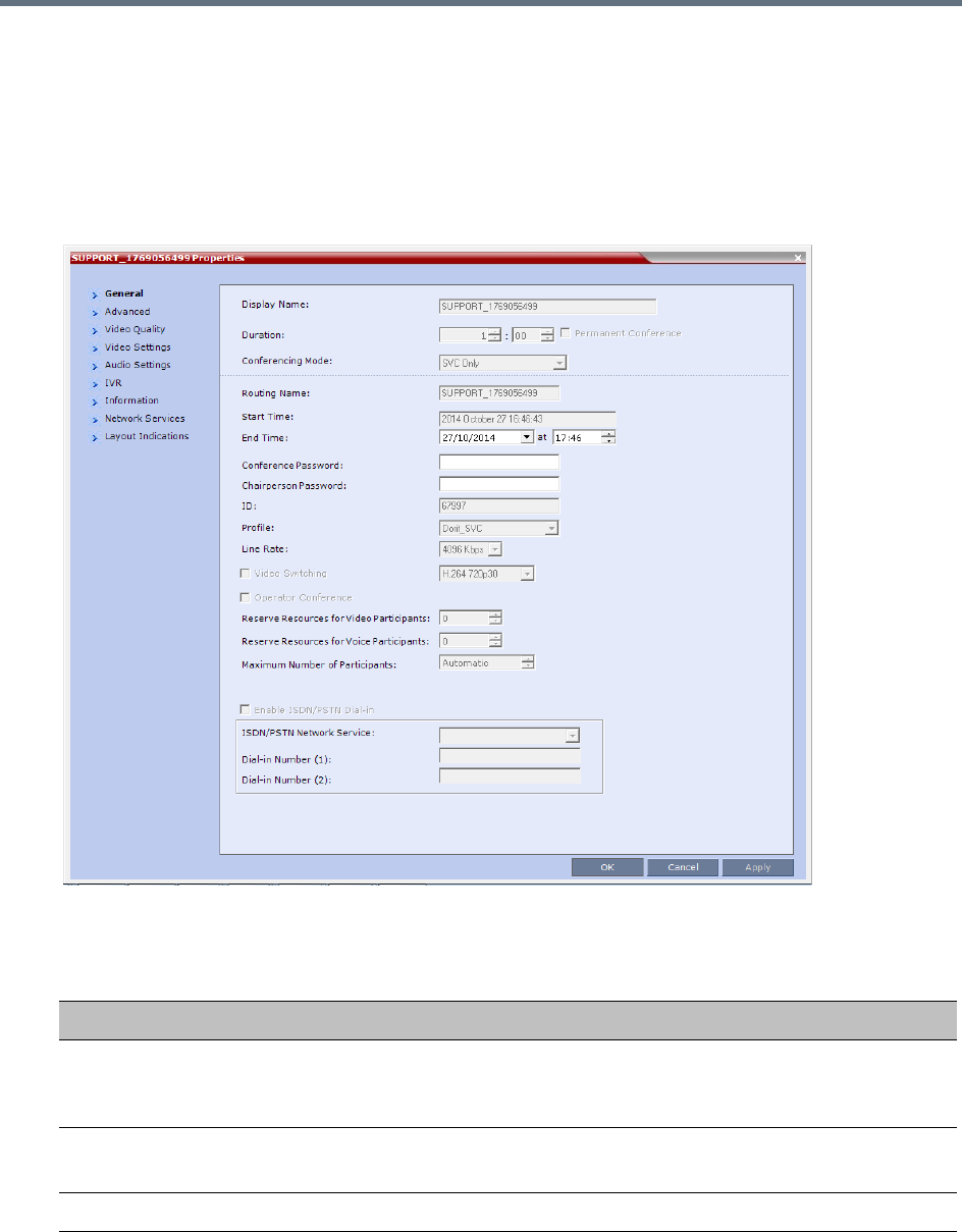
Conference and Participant Monitoring
Polycom®, Inc. 419
Viewing the Properties of Ongoing SVC Conferences
To view the parameters of an ongoing SVC conference:
1In the Conference list pane, double-click the SVC conference or right-click the SVC conference and
then click Conference Properties.
The Conference Properties - General dialog box with the General tab opens.
2The following information is displayed in the General tab:
Conference Properties - General Parameters
Field Description
Display Name The Display Name is the conference name in native language and Unicode
character sets to be displayed in the Collaboration Server Web Client.
Note: This field is displayed in all tabs.
Duration The expected duration of the conference using the format HH:MM.
Note: This field is displayed in all tabs.
Conferencing Mode The conferencing mode for the conference.

Conference and Participant Monitoring
Polycom®, Inc. 420
3Click the Advanced tab.
The Conference Properties - Advanced dialog box opens.
Routing Name The ASCII name of the conference. It can be used by H.323 and SIP participants
for dialing in directly to the conference. It is used to register the conference in the
gatekeeper and the SIP server.
Start Time The time the conference started.
End Time The expected conference end time.
Conference
Password
A numeric password for participants to access the conference.
Chairperson
Password
A numeric password used by participants to identify themselves as the conference
chairperson.
ID The conference ID.
Profile The name of the conference Profile from which conference parameters were taken.
Line Rate The maximum transfer rate, in kilobytes per second (Kbps) of the call (video and
audio streams).
Video Switching Video Switching is not supported in SVC conferences.
Reserve Resources
for Video Participants
Reserve Resources for Video Participants is not supported in SVC conferences.
Reserve Resources
for Audio Participants
Reserve Resources for Audio Participants is not supported in SVC conferences.
Max Number of
Participants
Indicates the total number of participants that can be connected to the conference.
The Automatic setting indicates the maximum number of participants that can be
connected to the MCU according to resource availability.
Enable ISDN/PSTN
Network Service
ISDN/PSTN participants are not supported in SVC conferences.
ISDN/PSTN Network
Service
ISDN/PSTN participants are not supported in SVC conferences.
Dial-in Number (1) ISDN/PSTN participants are not supported in SVC conferences.
Dial-in Number (2) ISDN/PSTN participants are not supported in SVC conferences.
Conference Properties - General Parameters
Field Description
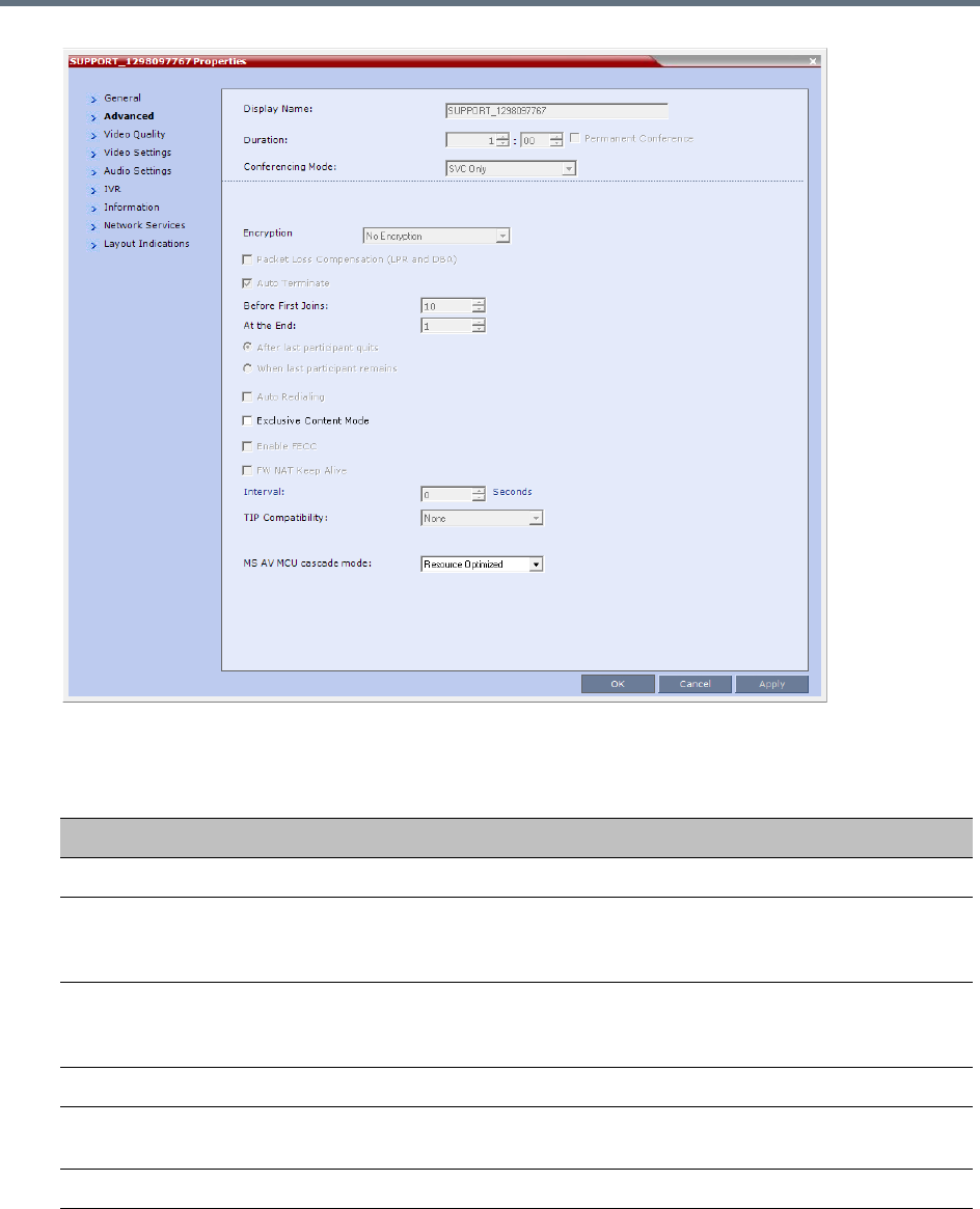
Conference and Participant Monitoring
Polycom®, Inc. 421
4The following information is displayed in the Advanced tab:
Conference Properties - Advanced Parameters
Field/Option Description
Encryption Indicates the Encryption setting for the conference.
Packet Loss
Compensation (LPR
and DBA)
Packet Loss Compensation is not supported in SVC conferences.
Auto Terminate When selected, indicates that the MCU will automatically terminate the conference
when Before First Joins, At the End-After Last Quits and At the End - When
Last Participant Remains parameters apply.
Auto Redialing Dial-out is not supported in SVC conferences.
Exclusive Content
Mode
When selected, Content is limited to one participant.
Enable FECC Far End Camera Control is not supported in SVC conferences.
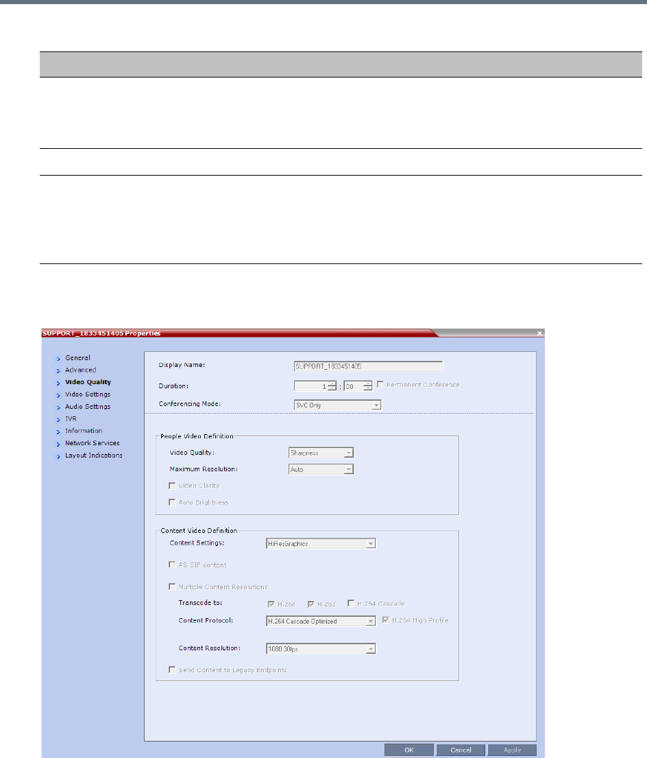
Conference and Participant Monitoring
Polycom®, Inc. 422
5Click the Video Quality tab.
The Conference Properties - Video Quality dialog box opens.
The following information is displayed:
FW NAT Keep Alive When selected, sends a FW NAT Keep Alive message at specific Intervals for the
RTP, UDP and BFCP channels. The interval specifies how often a FW NAT Keep
Alive message is sent. For more information, see RealPresence Collaboration
Server (RMX) Network Port Usage.
TIP Compatibility TIP Compatibility is not supported in SVC conferences.
MS AV MCU cascade
mode
This field is part of the Microsoft Lync utility and defines the resource usage in the
cascading relationship between Polycom RealPresence Collaboration Server and
Microsoft Lync server.
For more information see Video Resource Requirement Selection in Lync 2013
AVMCU Cascade.
Conference Properties - Advanced Parameters
Field/Option Description

Conference and Participant Monitoring
Polycom®, Inc. 423
Conference Properties - Video Quality Parameters
Field/Option Description
People Video Definition
Video Quality Indicates the resolution and frame rate that determine the video quality set for the
conference. In SVC conferencing, only Sharpness is supported.
Maximum Resolution In SVC conferencing, this is always Auto (default) - The Maximum Resolution
remains as selected in the Resolution Configuration dialog box.
Video Clarity Video Clarity is not supported in SVC conferences.
Auto Brightness Auto Brightness is not supported in SVC conferences.
Content Video Definition
AS-SIP AS-SIP is not supported in SVC conferences.
Multiple Content
Resolutions
Indicates if Multiple Content Resolutions mode for content sharing is enabled. In
this mode, content is shared in multiple streams, one for each video protocol: H.263
and H.264. This allows endpoints with different protocols to connect and disconnect
without having to restart Content sharing in the middle of a conference. For more
information, see Multiple Content Resolutions.
Content Settings Indicates the Content channel resolution set for the conference. Possible
resolutions are Graphics (default), Hi-res Graphics, Live Video, and Customized
Content Rate.
For more information, see Content Settings.
Content Protocol Indicates the Content Protocol used for content sharing in Highest Common
Content Sharing Mode.
For more information, see MCU Usage Modes of Content Protocols.
Content Resolution Indicates the Content Resolution and frame rate according to the selected Content
Sharing Mode (Highest common Content or Multiple Resolution Contents) and the
video protocol. For more information, see H.264 Cascade Optimized.
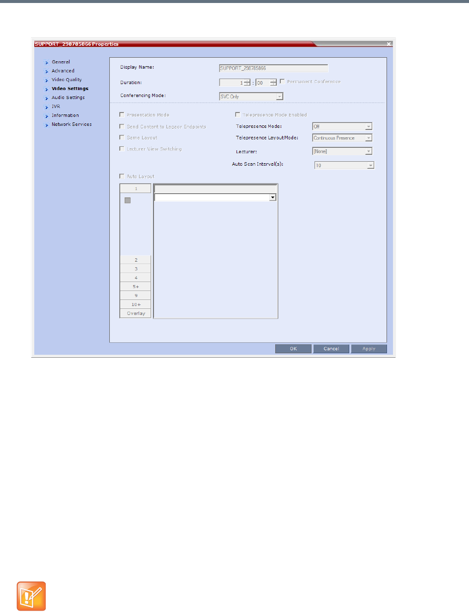
Conference and Participant Monitoring
Polycom®, Inc. 424
6Click the Video Settings tab to view the video parameters defined for the conference.
In SVC conferences, only Auto Layout is enabled and cannot be disabled. All other video settings are
disabled.
7Click the Audio Settings tab to view the audio parameters defined for the conference.
In SVC conferences, all Audio Settings options are disabled.
8Click the IVR tab to view the conference IVR settings.
9Click the Information tab to view general information defined for the conference. Changes made to
this information once the conference is running are not saved to the CDR.
10 Click the Network Services tab to view the conference IVR settings.
11 Click the Layout Indications tab to view the conference IVR settings.
12 Click OK to close the Conference Properties dialog box.
Monitoring of Operator Conferences and Participants Requiring
Assistance
This feature is applicable only in CP and Mixed CP and SVC conferences.
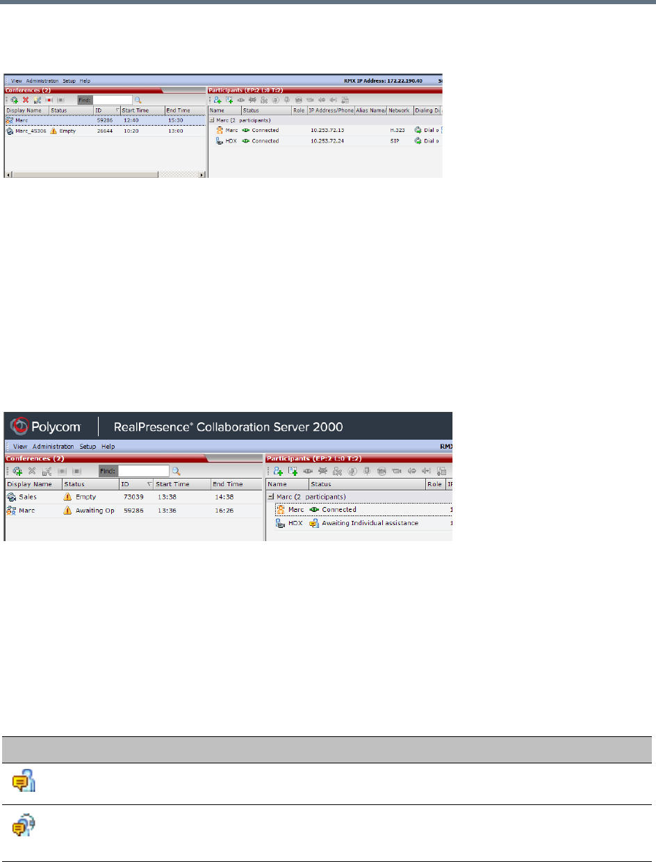
Conference and Participant Monitoring
Polycom®, Inc. 425
Operator conferences are monitored in the same way as standard ongoing conferences.
Each Operator conference includes at least one participant - the Operator.
You can view the properties of the Operator conference by double-clicking the conference entry in the
Conferences list or by right-clicking the conference entry and selecting Conference Properties.
Requesting Help
A participant can request help using the appropriate DTMF code from his/her touch tone telephone or the
endpoint’s DTMF input device. The participant can request Individual Assistance (default DTMF code *0) or
Conference Assistance (default DTMF code 00).
Participants in Entry Queues who failed to enter the correct destination conference ID or the conference
password will wait for operator assistance (provided that an Operator conference is active).
When requiring or requesting operator assistance, the Collaboration Server management application
displays the following:
●The participant’s connection Status changes, reflecting the help request. For details, see Participants
List Status Column Icons and Indications.
●The conference status changes and it is displayed with the exclamation point icon and the status
Awaiting Operator.
●The appropriate voice message is played to the relevant participants indicating that assistance will
be provided shortly.
The following icons and statuses are displayed in the Participant Status column:
Participants List Status Column Icons and Indications
Icon Status indication Description
Awaiting Individual Assistance The participant has requested the operator’s assistance for
himself/herself.
Awaiting Conference
Assistance
The participant has requested the operator’s assistance for the
conference. Usually this means that the operator is requested to
join the conference.
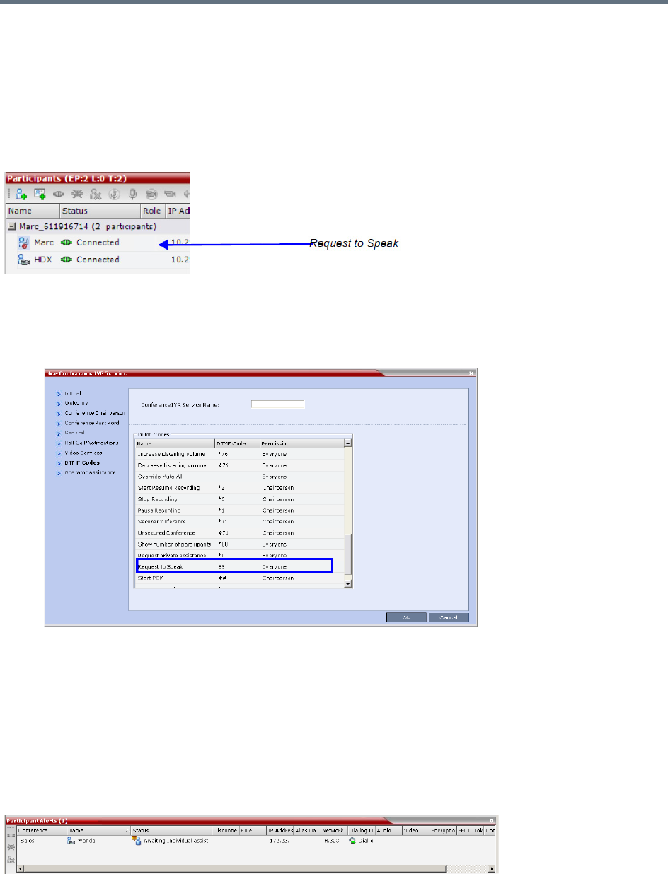
Conference and Participant Monitoring
Polycom®, Inc. 426
When the Operator moves the participant to the Operator conference for individual assistance the
participant Status indications are cleared.
Request to Speak
Participants that were muted by the conference organizer/system operator can indicate that they want to be
unmuted by entering the appropriate DTMF code.
An icon is displayed in the Role column of the Participants list for 30 seconds.
Request to Speak is:
●Activated when the participant enters the appropriate DTMF code (default: 99).
The DTMF code can be modified in the conference IVR Service Properties - DTMF Codes dialog
box.
●Available for dial-in and dial-out participants.
●A participant can request to speak more than once during the conference.
●Supported in all conference types.
●Supported in H.323 and SIP environments.
●The duration of the icon display cannot be modified.
Participant Alerts List
The Participant Alerts list contains all the participants who are currently waiting for operator assistance.

Conference and Participant Monitoring
Polycom®, Inc. 427
Participants are automatically added to the Participants Alerts list in the following circumstances:
●The participant fails to connect to the conference by entering the wrong conference ID or conference
password and waits for the operator’s assistance.
●The participant requests Operator’s Assistance during the ongoing conference.
This list is used as reference only. Participants can be assisted and moved to the Operator conference or
the destination conference only from the Participants list of the Entry Queues or ongoing conference where
they are awaiting assistance.
The participants are automatically removed from the Participant Alerts list when moved to any conference
(including the Operator conference).
Participant Level Monitoring
In addition to conference information, you can view detailed information regarding the status and
parameters of each listed participant, using the Participant Properties dialog box. Participant properties can
be displayed for all participants currently connected to a conference and for defined participants that have
been disconnected.
The table below lists the tabs in the Participant Properties dialog box, as viewed by each user type, for each
participant connection types.
Properties differ for IP and ISDN/PSTN participants.
SIP SVC-based participant properties are similar to SIP AVC-based participant properties.
Participant monitoring - Tab list per participant connection type and user
Tab Name
Admin Chairperson Operator
AVC H.323 AVC/SVC SIP AVC H.323 AVC/SVC SIP AVC H.323 AVC/SVC SIP
General
Advanced
Information
Media Sources
H.245
SDP
Connection
Status
Channel Status
Channel Status -
Advanced
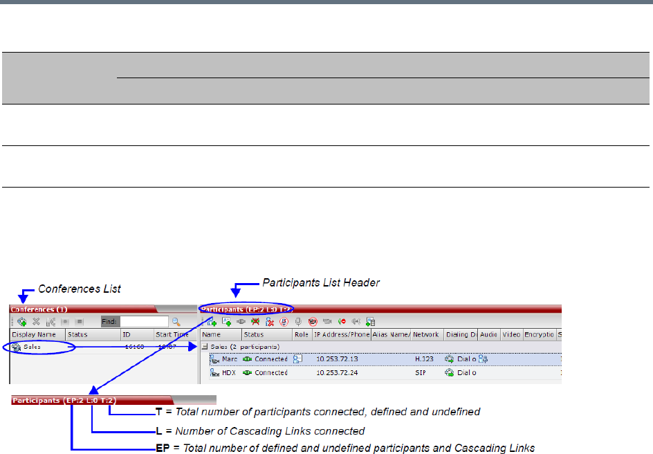
Conference and Participant Monitoring
Polycom®, Inc. 428
Participant Connection Monitoring (AVC and SVC-based Connections)
When a conference is selected in the Conference list, the Participants list header displays a summary of
participant connection status.
These numbers include:
●EP = the number of Endpoints currently connected to the conference (both defined and undefined
participants). This number includes participants whose status is connected with problem, connected
partially or connected as secondary.
Connected Cascading Links are not included and are detailed separately.
●L = the number of Cascading Links currently connected to the conference.
●T = the total number of all:
connected Participants - both defined and undefined participants
defined participants that are currently disconnected
Cascading Links - both connected and disconnected
If more than one conference is selected, the EP:n L:n T:n numbers reflect the cumulative connection status
information of all the selected conferences.
If no conference is selected, the EP:n L:n T:n numbers are all zeroed.
If the T(otal) number of participants is higher than the number of connected participants, it indicates that
additional participants defined for the conference have not yet connected. For example, if the EP: is 12 and
the T: is 15, it means that 12 out of 15 of the expected participants have connected and that 3 defined
participants have not yet connected.
The Participant list displays the following participant indicators and properties:
Gatekeeper
Status
Call Admission
Control
Participant monitoring - Tab list per participant connection type and user
Tab Name
Admin Chairperson Operator
AVC H.323 AVC/SVC SIP AVC H.323 AVC/SVC SIP AVC H.323 AVC/SVC SIP
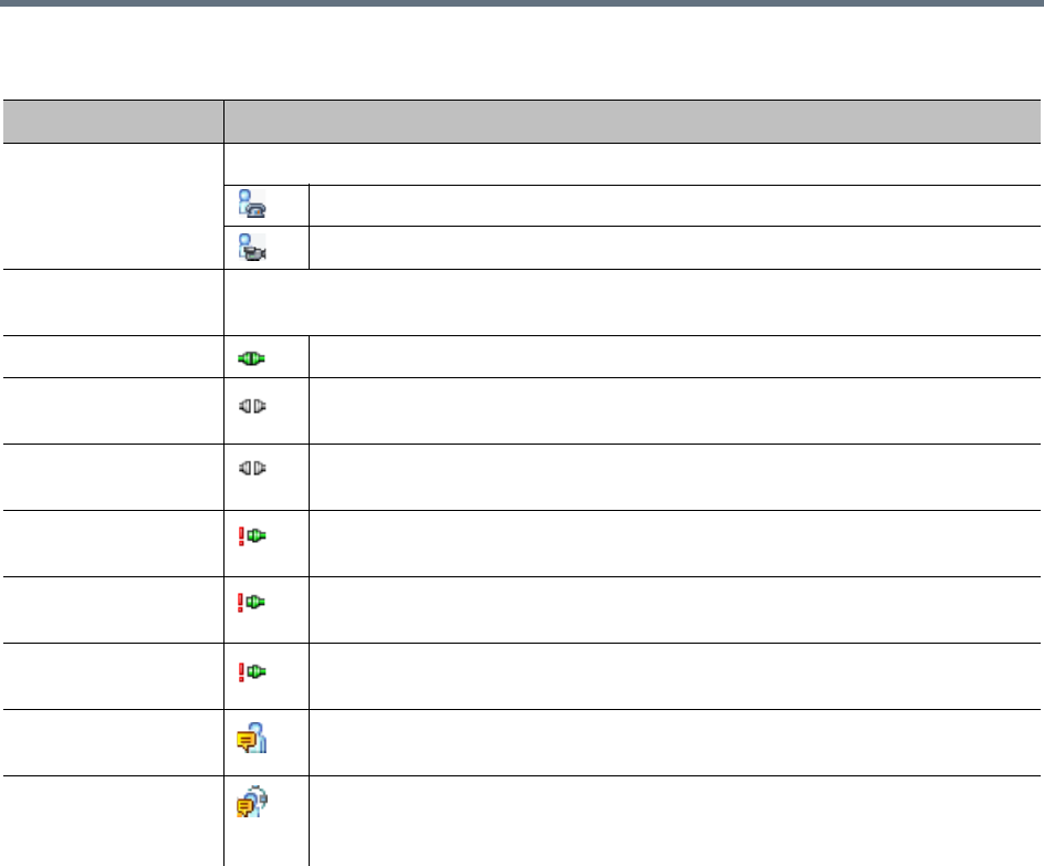
Conference and Participant Monitoring
Polycom®, Inc. 429
Participant Monitoring – Indicators and Properties
Column Icon/Description
Name Displays the name and type (icon) of the participant:
Audio Participant – Connected via IP phone or ISDN/PSTN.
Video Participant – Connected with audio and video channels.
Status Displays the connection status (text and icon) of the participant. If there is no problem with
the participant’s connection no indication is displayed.
Connected – The participant is successfully connected to the conference.
Disconnected – The participant is disconnected from the conference. This
status applies only to defined participants.
Waiting for Dial-in – The system is waiting for the defined participant to dial into
the conference.
Partially Connected – The connection process is not yet complete; the video
channel has not been connected.
Faulty Connection – The participant is connected, but problems occurred in the
connection, such as synchronization loss.
Secondary Connection – The endpoint’s video channel cannot be connected to
the conference and the participant is connected only via audio.
Awaiting Individual Assistance (AVC-based connection) – The participant has
requested the user’s (operator’s) assistance.
Awaiting Conference Assistance (AVC-based connection) – The participant
has requested the operator’s assistance for the conference. This usually means
that the user (operator) has been requested to join the conference.
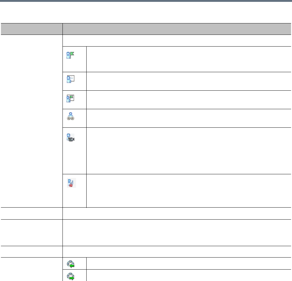
Conference and Participant Monitoring
Polycom®, Inc. 430
Role Displays the participant’s role or function in the conference:
Chairperson – The participant is defined as the conference chairperson. The
chairperson can manage the conference using touch-tone signals (DTMF
codes).
Lecturer (AVC-based connection) – The participant is defined as the conference
Lecturer.
Lecturer and Chairperson – The participant is defined as both the conference
Lecturer and Chairperson.
Cascade-enabled Dial-out Participant (AVC-based connection) – A special
participant functioning as a link in a cascaded conference.
Recording (AVC-based connection) – A special participant functioning as a
Recording Link.
Note: The Recording participant does not support H.264 High Profile. If
recording a conference set to H,264 High Profile, the Recording participant
connects as Audio Only and records the conference Audio while displaying the
recording icon for the conference.
Request to speak (AVC-based connection) - Participants that were muted by
the conference organizer/system operator can indicate that they want to be
unmuted by entering the appropriate DTMF code (default 99).
The icon is displayed for 30 seconds.
IP Address/Phone The IP participant’s IP address or the ISDN/PSTN participant’s phone number.
Alias Name/
SIP Address
The participant’s Alias Name or SIP URI.
The alias of an RealPresence Capture Server or RSS system if the participant is
functioning as a recording link.
Network The participant’s network connection type – H.323, or SIP or ISDN/PSTN.
Dialing Direction Dial-in – The participant dialed the conference.
Dial-out – The MCU dialed the participant.
Participant Monitoring – Indicators and Properties
Column Icon/Description
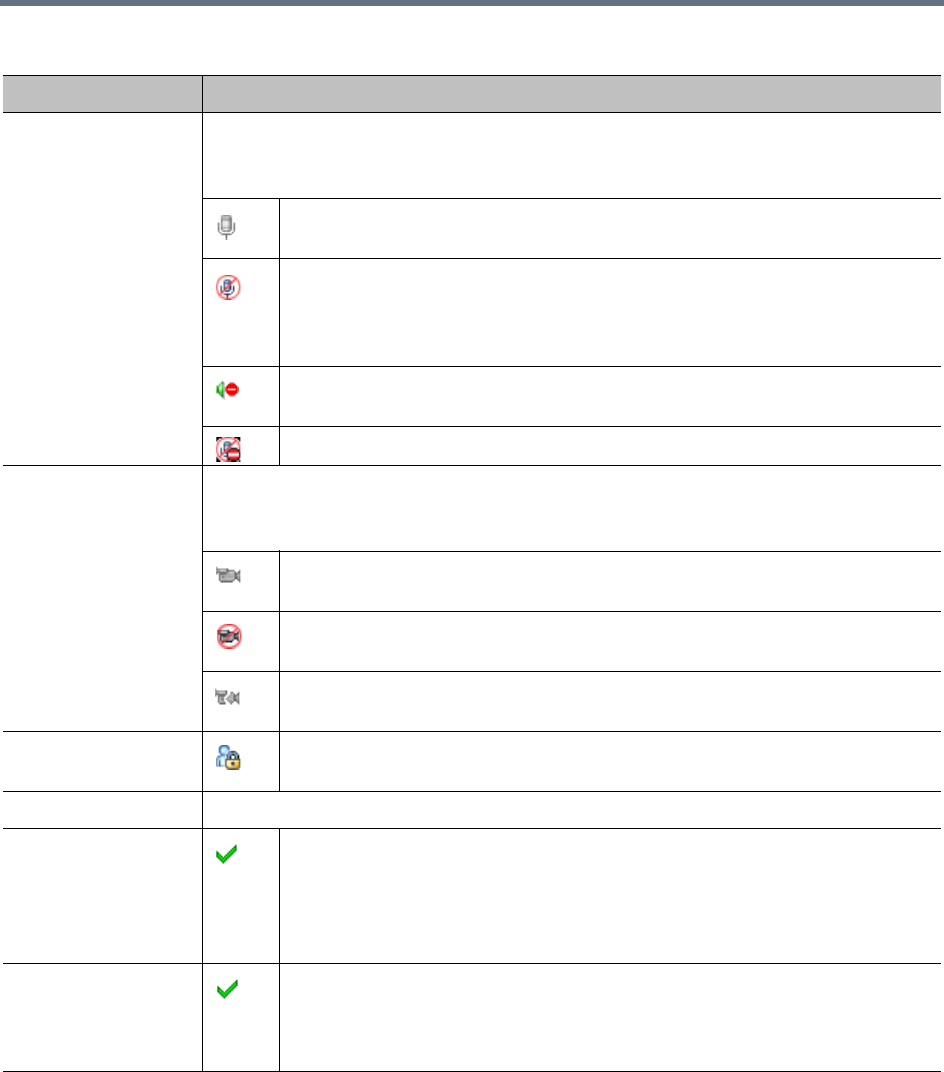
Conference and Participant Monitoring
Polycom®, Inc. 431
Audio Displays the status of the participant’s audio channel.
If the participant’s audio is connected and the channel is neither muted nor blocked, no
indication is displayed.
Disconnected – Participant’s audio channel is disconnected. This is a defined
participant who is waiting to be connected to the conference.
Muted – Participant’s audio channel is muted. Indicates who initiated the Mute:
participant, Collaboration Server User or MCU. The participant can still hear the
conference.
Blocked – Transmission of audio from the conference to the participant is
blocked.
Muted and Blocked - Audio channel is muted and blocked.
Video Displays the status of the participant’s video channel.
If there is no problem with the participant’s video connection and the channel is neither
suspended nor secondary, no indication is displayed.
Disconnected – Participant’s video channel is disconnected. This is a defined
participant who is waiting to be connected to the conference.
Suspended – Video transmission from the endpoint to the conference is
suspended.
Secondary – Participant is connected only through the audio channel due to
problems with the video channel.
Encryption (AVC-based connection) Indicates that the endpoint is connected to the
conference using encryption.
Service Name Displays the IP Network Service used to connect this participant to the conference.
FECC Token Participant is the holder of the FECC token and has Far End Camera Control
capabilities.
The FECC token can be allocated to only one participant at a time and remains
un-allocated if no participant requests it.
Note: FECC is not supported with ISDN.
Content Token Participant is the holder of the Content token and has content sharing
permission.
The Content token can be allocated to only one participant at a time and remains
un-allocated if no participant requests it.
Participant Monitoring – Indicators and Properties
Column Icon/Description
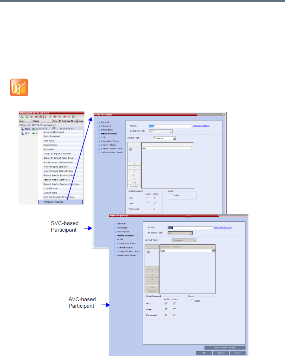
Conference and Participant Monitoring
Polycom®, Inc. 432
Viewing the Properties of Participants
To view the participant Properties:
»In the Participant List pane double-click the participant entry. Alternatively, right-click a participant
and then click Participant Properties.
The Participant Properties dialog box opens, displaying the last opened tab.
The Media Sources dialog box enables you to mute participant’s audio, suspend participant’s video
transmission and select a personal Video Layout for the participant.
Media Sources properties are not available for SVC participants.
Conference and Participant Monitoring
Polycom®, Inc. 433
Monitoring IP Participants
The following parameters are displayed for an IP participant.
For ISDN/PSTN participants, only the following tabs are displayed in the Participant Properties dialog
box:
•General, Advanced, Information
•Media Sources
•Connection Status
•Channel Status
The General, Advanced and Information tabs include the same properties for new and defined
participants. For more information, see Adding a Participant to the Address Book.
Participant Properties - Media Sources Parameters
Field Description
Name Indicates the participant’s name.
Note: This field is displayed in all tabs.
Endpoint Website
(link)
Click the Endpoint Website hyperlink to connect to the internal website of the participant’s
endpoint. It enables you to perform administrative, configuration and troubleshooting
activities on the endpoint.
The connection is available only if the IP address of the endpoint’s internal site is filled in
the Website IP Address field in the Participant Properties - General dialog box.
Note: This field is displayed in all tabs (excluding ISDN/PSTN participants).
Endpoint Website hyperlinks are not supported when the Collaboration Server is in Ultra
Secure Mode. For more information see Ultra Secure Mode.
Endpoint Type Indicates whether the participant is using an AVC-based or SVC-based endpoint.
Fields, tabs and options are enabled or disabled according to the endpoint type.
Note: This field is displayed in all tabs.
Layout Type Indicates whether the video layout currently viewed by the participant is the Conference or
Personal Layout.
If Personal Layout is selected, you can select a Video Layout that will be viewed only by
this participant.
Video Layout Indicates the video layout currently viewed by the participant. When Personal Layout is
selected in the Layout Type you can force participants to the video windows in a layout
that is specific to the participant. For more information, see Setting the Video Layout in
Cascading conferences.
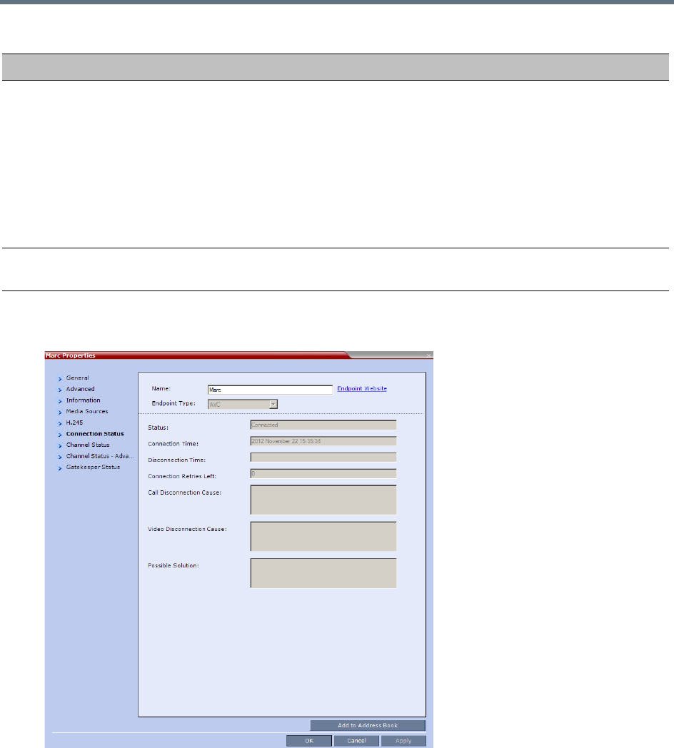
Conference and Participant Monitoring
Polycom®, Inc. 434
1Click the Connection Status tab to view the connection status, and if disconnected the cause of the
disconnection.
This dialog box is the same for AVC-based and SVC-based participants.
The following parameters are displayed:
Mute/Suspend Indicates if the endpoint’s audio and/or video channels have been muted/suspended. The
entity that initiated audio mute or video suspend is also indicated.
•MCU – Audio or Video channel has been muted/suspended by the MCU.
• User – Channels have been muted/suspended by the Collaboration Server user.
• Participant – Channels have been muted/suspended by the participant from the
endpoint.
You can also cancel or perform mute and suspend operation using these check boxes.
Note: If the participant muted his/her audio channel, the system displays the mute icon
only for H.323.
Block When checked, the audio transmission from the conference to the participant’s endpoint is
blocked, but the participant will still be heard by other participants.
Participant Properties - Media Sources Parameters
Field Description
Conference and Participant Monitoring
Polycom®, Inc. 435
Participant Properties - Connection Status Parameters
Field Description
Participant Status
Status Indicates the connection status of the participant.
Connection Time The date and time the participant connected to the conference.
Note: The time format is derived from the MCU’s operating system
time format.
Disconnection Time The date and time the defined participant disconnected from the
conference.
Connection Retries
Left
Indicates the number of retries left for the system to connect defined
participant to the conference.
Call Disconnection
Cause
Displays the cause for the defined participant’s disconnection from
the conference. See Conference and Participant Monitoring.
Video Disconnection
Cause
Displays the cause the video channel could not be connected. For
more information, see Appendix A - Disconnection Causes.
Possible Solution In some cases, a possible solution is indicated to the cause of the
video disconnection.
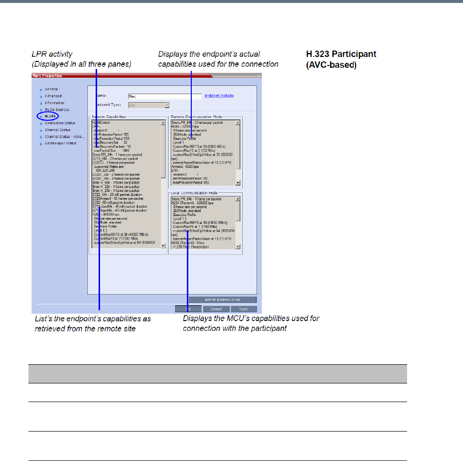
Conference and Participant Monitoring
Polycom®, Inc. 436
2Click the H.245 (H.323) or SDP (SIP) tab during or after the participant’s connection process to view
information that can help in resolving connection issues.
3Click on the Channel Status tab to view the status of the various channels.
Participant Properties - H.245/SDP Parameters
Field Description
Remote Capabilities Lists the participant’s capabilities as declared by the endpoint.
Remote
Communication Mode
Displays the actual capabilities used by the endpoint when
establishing the connection with the MCU (Endpoint to MCU).
Local Communication
Mode
Displays the actual capabilities used by the MCU when establishing
the connection with the participant’s endpoint (MCU to Endpoint).
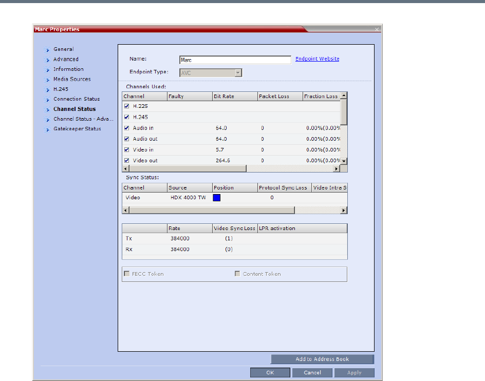
Conference and Participant Monitoring
Polycom®, Inc. 437

Conference and Participant Monitoring
Polycom®, Inc. 438
The following parameters are displayed:
Participant Properties - Channel Status Parameters
Field Description
Channels Used When checked, indicates the channel type used by the participant to connect to the
conference: Incoming channels are endpoint to MCU, Outgoing channels are from
MCU to endpoint.
Channels:
• H.225/Signaling - The call-signaling channel.
• H.245/SDP - The Control channel.
• Audio in - Incoming audio channel
• Audio out - Outgoing audio channel
• Video in - Incoming video channel
• Video out - Outgoing video channel
• Content in - H.239/People+Content conferences
• Content out - H.239/People+Content conferences
• FECC in - The incoming FECC channel is open.
• FECC out - The outgoing FECC channel is open.
Columns:
•Faulty – A red exclamation point indicates a faulty channel condition. This is a
real-time indication; when resolved the indication disappears. An exclamation
point indicates that further investigation may be required using additional
parameters displayed in the Advanced Channel Status tab.
•Bit Rate – The actual transfer rate for the channel. When channel is inactive, bit
rate value is 0. For example, if the participant is connected without video, the bit
rate for the video channel is 0.
Note: The CTS Audio Auxiliary channel is used only for Content. In all other
cases, the bit rate shown in this column for this channel is 0.
• Packet Loss – The accumulated count of all packets that are missing according
to the RTCP report since the channel was opened. This field is relevant only
during the connection stage and does not display faulty indications.
• Fraction Loss (Peak) – The ratio between the number of lost packets and the
total number of transmitted packets since the last RTCP report. Peak (in
parentheses) indicates the highest ratio recorded since the channel was opened.
• Number of Packets – The number of received or transmitted packets since the
channel has opened. This field does not cause the display of the faulty indicator.
• Jitter (Peak) – Displays the network jitter (the deviation in time between the
packets) as reported in the last RTCP report (in milliseconds). Peak (in
parentheses) reflects the maximum network jitter since the channel was opened.
• Latency – Indicates the time it takes a packet to travel from one end to another
in milliseconds (derived from the RTCP report).
High latency value may indicate that there is a problem in the network, or that
the endpoint is sending an incorrect RTCP values.

Conference and Participant Monitoring
Polycom®, Inc. 439
4Click the Channel Status Advanced tab to view additional information for selected audio and video
channels.
Sync Status •Channel - The channel type: Video or Content.
•Source - The name of the participant currently viewed by this participant.
•Position - The video layout position indicating the place of each participant as
they appear in a conference.
• Protocol Sync Loss - Indicates whether the system was able to synchronize the
bits order according to the selected video protocol.
• Video Intra Sync - Indicates whether the synchronization on a video Intra frame
was successful.
• Video Resolution - The video resolution of the participant.
Rx - Rate The received line rate.
Tx - Rate The transmitted line rate.
Tx - Video Sync Loss When checked, indicates a video synchronization problem in the outgoing channel
from the MCU.
The counter indicates the sync-loss count.
Rx - Video Sync Loss When checked, indicates a video synchronization problem in the incoming channel
from the endpoint.
The counter indicates the sync-loss count.
Tx - LPR Activation When checked, indicates LPR activation in the outgoing channel.
Rx - LPR Activation When checked, indicates LPR activation in the incoming channel.
FECC Token When checked, indicates that the participant is the holder of the FECC Token.
Content Token When checked, indicates that the participant is the holder of the Content Token.
Participant Properties - Channel Status Parameters
Field Description
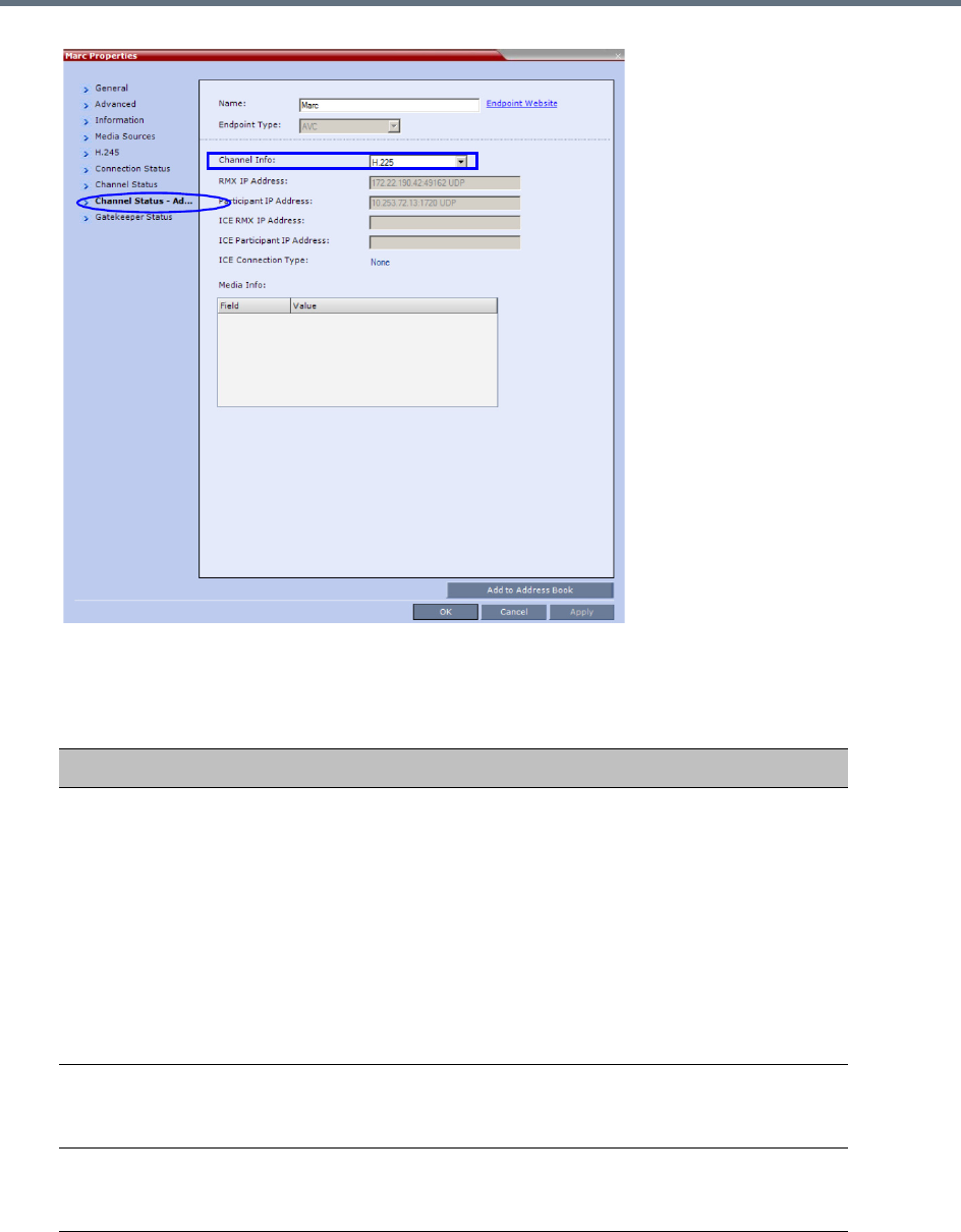
Conference and Participant Monitoring
Polycom®, Inc. 440
In the Channel Status - Advanced tab, channels can be selected for viewing additional information:
Participant Properties - Channel Status Advanced Parameters
Field Description
Channel Info Select a channel to view its information:
•H.225
•H.245
•Audio in
•Audio out
•Video in
•Video out
•Content in
•Content Out
•SIP BFCP TCP
Collaboration Server
IP Address
The IP address and the transport protocol (TCP/UDP) of the MCU to
which the participant is connected and the port number allocated to
the participant incoming media stream on the MCU side.
Participant IP
Address
The IP address and the transport protocol (TCP/UDP) of the
participant and the port number allocated to the media stream on the
participant side.
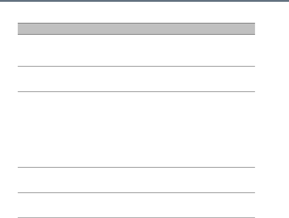
Conference and Participant Monitoring
Polycom®, Inc. 441
ICE RealPresence
Collaboration Server
1500/1800/2000/400
0 IP Address
The IP address, port number, and transport protocol of the MCU used
to pass through the media when ICE is functional. See Monitoring
Participant Connections.
ICE Participant IP
Address
The IP address, port number, and transport protocol of the endpoint
used to pass through the media when ICE is functional. See
Monitoring the Participant Connection in ICE Environment.
ICE Connection Type Indicates the type of connection between the Collaboration Server
and the participant in the ICE environment:
•Local (or Host) - The endpoint (Remote) is on the same network
as the Collaboration Server and the media connection is direct,
using local addresses.
• Relay - Media between the Collaboration Server and the
participant passes through a media relay server.
• Firewall - Media connection between the Collaboration Server and
the participant is done using their external IP addresses (the IP
addresses as seen outside of the local network).
Media Info This table provides information about the audio and video parameters,
such as video algorithm, resolution, etc. For more information, see
Appendix E - Participant Properties Advanced Channel Information.
RTP Statistics This information may indicate problems with the network which can
affect the audio and video quality. For more information, see Appendix
E - Participant Properties Advanced Channel Information.
Participant Properties - Channel Status Advanced Parameters
Field Description
Conference and Participant Monitoring
Polycom®, Inc. 442
5 For H.323 AVC-based participants only - Click the Gatekeeper Status tab to view its parameters.
Participant Properties - Gatekeeper Status Parameters
Field Description
Requested
Bandwidth
The bandwidth requested by the MCU from the gatekeeper.
Allocated Bandwidth The actual bandwidth allocated by the gatekeeper to the MCU.
Required Info Interval Indicates the interval, in seconds, between registration messages
that the MCU sends to the gatekeeper to indicate that it is still
connected.
Gatekeeper State Indicates the status of the participant’s registration with the
gatekeeper and the bandwidth allocated to the participant. The
following statuses may be displayed:
•ARQ – Admission Request - Indicates that the participant has
requested the gatekeeper to allocate the required bandwidth on
the LAN.
• Admitted – Indicates that the gatekeeper has allocated the
required bandwidth to the participant.
•DRQ – Disengage Request – The endpoint informs the gatekeeper
that the connection to the conference is terminated and requests
to disconnect the call and free the resources.
•None – Indicates that there is no connection to the gatekeeper.
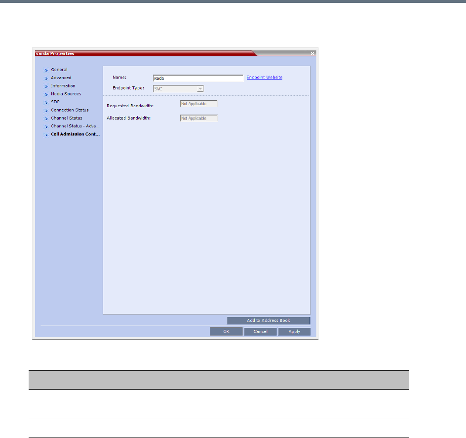
Conference and Participant Monitoring
Polycom®, Inc. 443
6 For SIP AVC-based and SVC-based participants - Click the Call Admission Control tab to view
its parameters.
Participant Properties - Gatekeeper Status Parameters
Field Description
Requested
Bandwidth
The bandwidth requested by the MCU from the SIP server.
Allocated Bandwidth The actual bandwidth allocated by the SIP server to the MCU.
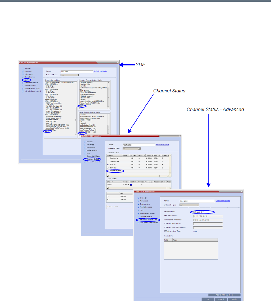
Conference and Participant Monitoring
Polycom®, Inc. 444
Monitoring SIP BFCP Content
In the SIP Participant Properties dialog box, BFCP status information appears in:
●All three panes of the SDP tab.
●The Channel Status tab.
●The Channel Status - Advanced tab.
For more information see Participant Level Monitoring.

Conference and Participant Monitoring
Polycom®, Inc. 445
Detecting Endpoint Disconnection
Endpoint disconnect can be detected for
●SIP endpoints - Detecting SIP Endpoint Disconnection
●H.323 endpoints - H.323 Endpoint Disconnection Detection
Detecting SIP Endpoint Disconnection
When an abnormal disconnection of SIP endpoints occurs because of network problems or client
application failures, SIP endpoints remain connected to the conference causing connection disruptions. For
example, the video freezes in the layout or blocks content for SIP endpoints when a quick re-connection is
performed. It can take several minutes to detect the SIP endpoint disconnection using the SIP standard
behavior.
In a normal SIP video call, audio and video (RTP and RTCP) messages are sent from the endpoints to the
MCU to detect the signaling of connected endpoints. Conversely, SVC endpoints might not send video RTP
messages to the MCU when a participant is not displayed in the video layout of any of the participants in the
conference. For SVC endpoints, the MCU will only verify audio RTP and RTCP messages and video RTCP
messages. Video RTP messages will not be checked.
To detect the disconnection of SIP endpoints in a reasonable amount of time, a new system flag can be
defined to specify the amount of time that the MCU should wait for an RTCP or RTP message from the SIP
endpoint before the endpoint starts the disconnection process. The system default value is automatically
set to 20 seconds.
The system flag, DETECT_SIP_EP_DISCONNECT_TIMER, contains the amount of time in seconds to wait
for an RTCP or RTP message to be received from the endpoint. When the time that was set in the system
flag has elapsed and no RTCP or RTP audio or video message has been received on either the audio or
the video channel, the MCU disconnects the SIP endpoint from the conference. A CDR event record is
created with a Call Disconnection Cause of SIP remote stopped responding.
The Microsoft Lync add-in endpoint opens audio and content channels. Lync endpoints can send
RTCP/RTP messages and empty RTP audio messages. When the time that was set in the system flag has
elapsed and no RTCP or RTP message has been received on the audio channel, the MCU disconnects the
endpoint from the conference.
SIP audio only endpoints use the audio channel only. When the time that was set in the system flag has
elapsed and no RTCP or RTP message has been received on the audio channel, the MCU disconnects the
SIP audio endpoint from the conference.
Configuring the System Flag
The time out used for SIP endpoint disconnection detection is controlled by the
DETECT_SIP_EP_DISCONNECT_TIMER System Flag which must be added to the System Configuration
to view or modify its value.
Range: 0 - 300
When the value is set between 0 and 14, the feature is disabled and SIP endpoints are not detected for
disconnection. When the value is set between 15 and 300, the feature is enabled.
Default: 20
For more information see , and Modifying System Flags.

Conference and Participant Monitoring
Polycom®, Inc. 446
H.323 Endpoint Disconnection Detection
In versions previous to version 8.4, when an H.323 endpoint disconnected, round trip messages were still
received, even when a gatekeeper was deployed. Because of this, the MCU failed to detect the endpoint
disconnection.
From version 8.4 onward, the MCU detects H.323 endpoint connection or disconnection by monitoring
RTCP/RTP messages reception using either the audio or video channels. When these messages are not
received within a predefined timeout interval, the endpoint is considered disconnected. Therefore as long
as either RTCP or RTP messages (interchangeably) are received on either of the video or audio channels,
the endpoint is considered connected.
If no messages are received through either channel within the predefined time out interval, the endpoint is
disconnected, and a disconnection message, H.323 remote stopped responding, is sent to the
endpoint.
No channel disconnection detection occurs while an endpoint’s video or audio are muted, or while the
endpoint is put on hold.
In audio calls, only the audio channel is polled for RTCP/RTP messages.
System Configuration Flag
The time out used for H.323 endpoint disconnection detection is controlled by the
DETECT_H323_EP_DISCONNECT_TIMER System Flag which must be added to the System
Configuration to view or modify its value.
Range: 16 - 300 (4-second units). Values indivisible by 4 will be rounded upward. Flag values between 0
and 15 disable the flag functionality.
Default: 20
For more information see , and Modifying System Flags.
Monitoring ISDN/PSTN Participants
Using the Participant Properties dialog box, you can monitor and verify the properties of an ISDN/PSTN
participant. The dialog box’s tabs contain information that is relevant to the participant’s status only while
the conference is running and is used to monitor the participant’s status when connection problems occur.
The table below lists the audio algorithms that are supported for ISDN participants according to their
connection bit rate
Maximum line rate at which ISDN endpoints can connect to a conference is 768 kbps.
Conference and Participant Monitoring
Polycom®, Inc. 447
:
Supported Audio Algorithms vs Bit Rate
Bit Rate
96Kbps
(and Lower) 128Kbps – 192Kbps
256Kbps (and
Higher)
Audio
Algorithm
G722.1 16K G722.1 C 32K G722.1 C 48K
G722.1 C 24K G722.1 C 24K G722.1 C 32K
Siren14 24K Siren14 32K G722.1 C 24K
G722 48K Siren14 24K Siren14 48K
G722 56K G722.1 32K Siren14 32K
G722 64K G722.1 24K Siren14 24K
G711 56K G722 48K G722.1 32K
G711 64K G722 56K G722.1 24K
G722 64K G722.1 16K
G711 56K G722 48K
G711 64K G722 56K
G722 64K
G711 56K
G711 64K
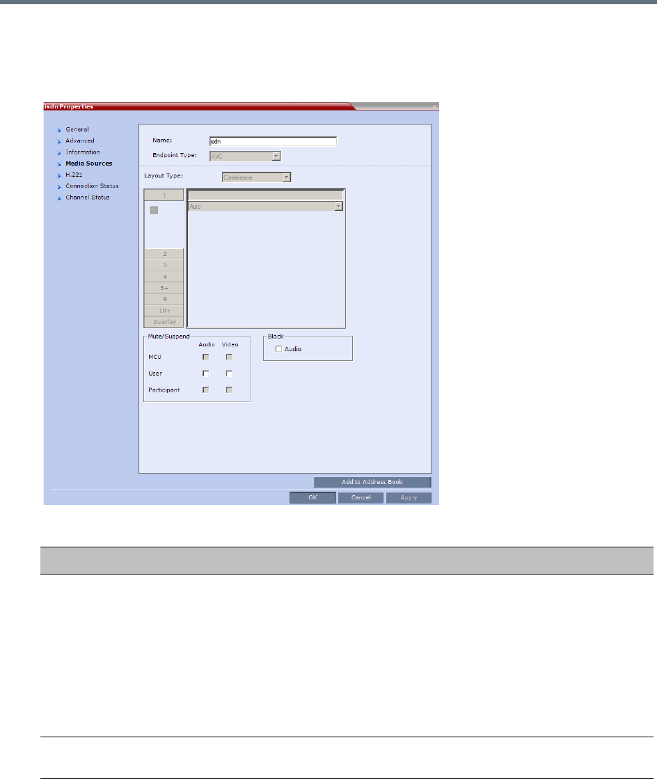
Conference and Participant Monitoring
Polycom®, Inc. 448
To view the participant properties during a conference:
1In the Participants list, right click the desired participant and select Participant Properties.
The Participant Properties - Media Sources dialog box is displayed.
ISDN/PSTN Participant Properties - Media Sources
Field Description
Mute/Suspend Indicates if the endpoint’s audio and/or video channels from the endpoint have been
muted/suspended.
The entity that initiated audio mute or video suspend is also indicated.
•MCU – Audio or Video channel has been muted/suspended by the MCU.
• User – Channels have been muted/suspended by the Collaboration Server user.
• Participant – Channels have been muted/suspended by the participant from the
endpoint.
You can also cancel or perform mute and suspend operation using these check
boxes.
Block (Audio) When checked, the audio transmission from the conference to the participant’s
endpoint is blocked, but the participant will still be heard by other participants.
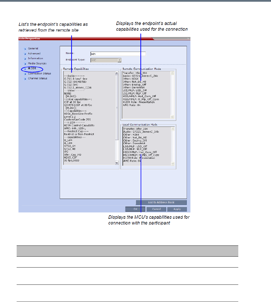
Conference and Participant Monitoring
Polycom®, Inc. 449
2Click the H.221 tab to view additional information that can help to resolve connection issues.
Participant Properties - H.221 Parameters
Field Description
Remote Capabilities Lists the participant’s capabilities as declared by the endpoint.
Remote
Communication Mode
Displays the actual capabilities used by the endpoint when
establishing the connection with the MCU (Endpoint to MCU).
Local Communication
Mode
Displays the actual capabilities used by the MCU when establishing
the connection with the participant’s endpoint (MCU to Endpoint).
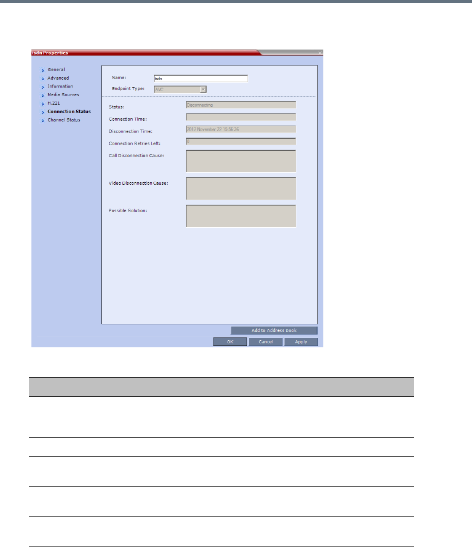
Conference and Participant Monitoring
Polycom®, Inc. 450
3Click the Connection Status tab to view general information regarding the participant connection
and disconnection causes of the participant to the conference.
ISDN/PSTN Participant Properties - Connection Status
Field Description
Status Indicates the connection status of the participant to the conference. If
there is a problem, the appropriate status is displayed, for example,
Disconnected.
Connection Time The date and time the participant connected to the conference.
Disconnection Time The date and time the participant was disconnected from the
conference.
Connection Retries
Left
Indicates the number of retries left for the system to connect the
participant to the conference.
Call Disconnection
Cause
For a full list of Disconnection Causes, Appendix A - Disconnection
Causes.
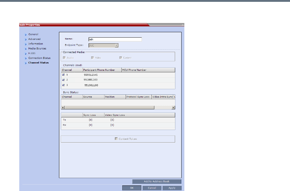
Conference and Participant Monitoring
Polycom®, Inc. 451
4Click the Channel Status tab to view the status of a participant’s channels.
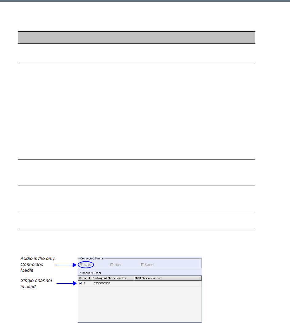
Conference and Participant Monitoring
Polycom®, Inc. 452
The Connected Media and Channels Used fields of an Audio Only participant are displayed as
follows:
ISDN/PSTN Participant Properties - Channel Status
Field Description
Connected Media Indicates if the participant is connected with Audio, Video and
Content media channels.
Channels Used •Channel – Indicates the channel used by the participants and
whether the channel is connected (indicated with a check mark) or
disconnected.
• Participant Phone Number – In a dial-in connection, indicates the
participant’s CLI (Calling Line Identification) as identified by the
MCU.
In a dial-out connection, indicates the participant’s phone number
dialed by the MCU for each channel.
• MCU Phone Number – In a dial-in connection, indicates the MCU
number dialed by the participant.
In a dial-out connection, indicates the MCU (CLI) number as seen
by the participant. This is the number entered in the MCU Number
field in the Network Service.
Tx - Video Sync Loss When checked, indicates a video synchronization problem in the
outgoing channel from the MCU.
The counter indicates the sync-loss count.
Rx - Video Sync Loss When checked, indicates a video synchronization problem in the
incoming channel from the endpoint.
The counter indicates the sync-loss count.
Content Token A check mark indicates that the participant is the current holder of the
Content Token.
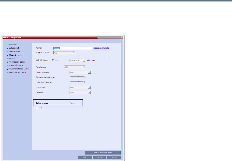
Conference and Participant Monitoring
Polycom®, Inc. 453
Monitoring Telepresence Participant Properties
A Telepresence status indicator is displayed in the Participant Properties - Advanced tab when
monitoring conference participants.
The Telepresence mode of the participant is indicated:
●RPX - The participant’s endpoint is transmitting 4:3 video format.
●TPX - The participant’s endpoint is transmitting 16:9 video format.
●None - The participant’s endpoint is neither RPX nor TPX.

Polycom, Inc. 454
Recording and Streaming Conferences
Conferences running on the Collaboration Server can be recorded using Polycom RealPresence® Capture
Server in the following ways:
●Capture Server dials in MCU for conference recording via an SIP interface from Capture Server. From
the Capture Server Admin UI, you can start a conference recording by dialing out to a Collaboration
Server. After the Collaboration Server gets the request from the Capture Server, the recording will
start if the recording is enabled on the Collaboration Server. During the conference recording, you
can pause or stop the recording from the Capture Server Admin UI. Refer to the Polycom
RealPresence Capture Server User’s Guide on how to start a recording by dialing out to an
interoperable endpoint.
●Collaboration Server dials out to Capture Server for a conference recording. Recording conferences
is enabled via a dial-out Recording Link, which is a dial-out connection from the conference to the
recording system.
The recording system can be installed at the same site as the conferencing MCU or at a remote site. Several
MCU’s can share the same recording system.
Recording conferences is enabled via a Dial Out Recording Link, which is a dial-out connection from the
conference to the recording system.
Recording can start automatically, when the first participant connects to a conference, or on request, when
the Collaboration Server user or conference chairperson initiates it.
Multiple Dial Out Recording Links may be defined.
Conference Dial Out Recording Links can be associated on the Collaboration Server with Virtual Recording
Rooms (VRR), created and saved on Polycom® RealPresence Capture Server (or RSS - Recording and
Streaming Server).
Each Dial Out Recording Link defined on the Collaboration Server can be given a descriptive name and can
be associated with one VRR saved on the Polycom RealPresence Capture Server or RSS 4000 systems.
The following guidelines apply:
●A Dial Out Recording Link that is being used by an ongoing conference cannot be deleted.
●A Dial Out Recording Link that is assigned to a Profile cannot be deleted.
●The Dial Out Recording Link supports H.264 High Profile with H.323 connections.
●While a Profile is being used in an ongoing conference, it cannot have a different Dial Out Recording
Link assigned to it.
Conference recording is applicable for AVC conferences only.

Recording and Streaming Conferences
Polycom, Inc. 455
●Up to 100 Dial Out Recording Links can be listed for selection in the Conference Profile.
●Multiple Dial Out Recording Links are supported in Continuous Presence and Video Switched
conferences.
●The number of Dial Out Recording Links available for selection is determined by the value of the
MAXIMUM_RECORDING_LINKS System Flag in system.cfg. Default value is 20 Dial Out Recording
Links.
●The Dial Out Recording Link can be encrypted when recording from an encrypted conference to the
RealPresence Capture Server or RSS system that is set to encryption. For more details, see Dial Out
Recording Link Encryption.
Creating Multiple Virtual Recording Rooms on the
RealPresence Capture Server or RSS Systems
If the environment includes a RealPresence Capture Server or RSS 4000 (V8.5) system and you want to
associate Dial Out Recording Links on the Collaboration Server with Virtual Recording Rooms (VRR),
created and saved on the RealPresence Capture Server or RSS 4000 (V8.5) system perform the following
operations on the RealPresence Capture Server or RSS 4000 (V8.5) system:
1Modify the parameters of a recording Template to meet the recording requirements.
2Assign the modified recording Template to a VRR. The recording and streaming server will assign a
number to the VRR.
3Repeat step
1
and step
2
for each VRR to create additional VRRs.
For more information see the RealPresence Capture Server or RSS 4000 (V8.5) system User Guide.
Configuring the Collaboration Server to Enable
Recording
To make recording possible the following components you must be configured on the Collaboration Server:
●Dial Out Recording Link – Defines the connection between the conference and the recording
system.
●Recording-enabled Conference IVR Service – Recording DTMF codes and messages must be set
in the Conference IVR Service to enable recording-related voice messages to be played and to allow
the conference chairperson to control the recording process using DTMF codes.
●Recording-enabled Profile – Recording must be enabled in the Conference Profile assigned to the
recorded conference.
If Multiple Dial Out Recording Links are being defined for Virtual Recording Rooms (VRRs), created and
saved on the RealPresence Capture Server or RSS 4000 (V8.5) system, the
MAXIMUM_RECORDING_LINKS System Flag in system.cfg can be modified to determine the number of
Dial Out Recording Links available for selection.
●Range: 20 - 100
●Default: 20
The flag value can be modified by selecting the System Configuration option from the Setup menu. For more
information, see Modifying System Flags.
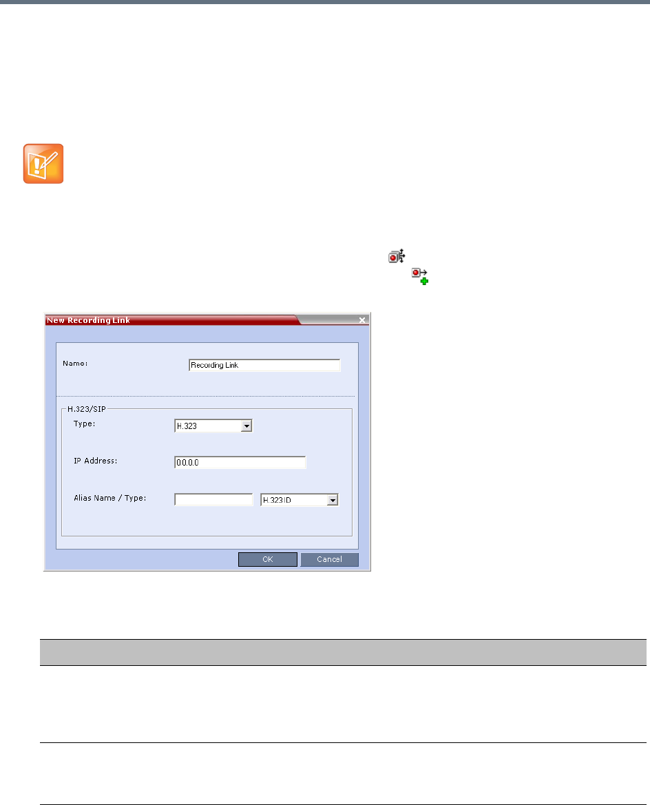
Recording and Streaming Conferences
Polycom, Inc. 456
Defining the Dial Out Recording Link
The Dial Out Recording Link is defined once and can be updated when the H.323 alias or the IP address
(of the recording system) is changed. Only one Dial Out Recording Link can be defined in the Collaboration
Server. Its type must be H.323.
To define a Dial Out Recording Link:
1In the RMX Management pane, click Recording Links ().
2In the Recording Links list, click the New Recording Link ( ) button.
The New Recording Link dialog box is displayed.
3Define the following parameters:
In Multiple Networks Configuration, Dial Out Recording Links use the default Network Service to
connect to conferences, therefore the recording system must be defined on the default IP Network
Service to enable the recording.
Recording Link Parameters
Parameter Description
Name Displays the default name that is assigned to the Recording Link.
If multiple Recording Links are defined, it is recommended to use a descriptive
name to be indicate the VRR to which it will be associated.
Default: Recording Link
Type Select the network environment:
•H.323
•SIP

Recording and Streaming Conferences
Polycom, Inc. 457
4Click OK.
The Dial Out Recording Link is added to the Collaboration Server unit.
Enabling the Recording Features in a Conference IVR Service
To record a conference, a Conference IVR Service in which the recording messages and DTMF codes are
activated must be assigned to the conference. The default Conference IVR Service shipped with the
Collaboration Server includes the recording-related voice messages and default DTMF codes that enable
the conference chairperson to control the recording process from the endpoint. You can modify these default
settings.
To modify the default recording settings for an existing Conference IVR Service:
1In the RMX Management pane, click IVR Services ().
The IVR Services are listed in the IVR Services list pane.
2To modify the default recording settings, double-click the Conference IVR Service or right-click and
select Properties.
The Conference IVR Service Properties dialog box is displayed.
IP Address •If no gatekeeper is configured, enter the IP Address of the RealPresence
Capture Server or RSS 4000 system. Example: If the RealPresence
Capture Server or RSS 4000 system IP address is 173.26.120.2, enter
173.26.120.2.
•If a gatekeeper is configured, you can either enter the IP address or an alias (see
the alias description).
Alias Name If using the endpoint’s alias instead of IP address, first select the alias type and
then enter the endpoint’s alias.
If you are associating this recording link to a VRR on the RealPresence Capture
Server or RSS 4000system, define the alias as follows:
•If you are using the RealPresence Capture Server or RSS 4000 systemIP
address, enter the VRR number in the Alias field. For example, if the VRR
number is 5555, enter 5555.
•Alternatively, if the Alias Type is set to H.323 ID, enter the RealPresence
Capture Server or RSS 4000system IP address and the VRR number in the
format:
<RealPresence_Capture_Server_or_RSS_4000_system_IP_Address>
##<VRR number>
For example: If the RealPresence Capture Server or RSS 4000 system IP
is 173.26.120.2 and the VRR number is 5555, enter 173.26.120.2##5555
Alias Type Depending on the format used to enter the information in the IP address and Alias
fields, select H.323 ID or E.164 (for multiple Recording links). E-mail ID and
Participant Number are also available.
Recording Link Parameters
Parameter Description
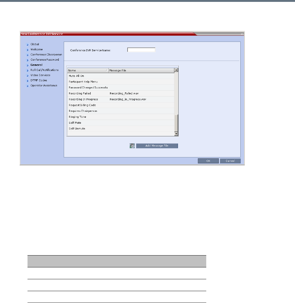
Recording and Streaming Conferences
Polycom, Inc. 458
3To assign voice messages other than the default, click the General tab and scroll down the list of
messages to the recording messages.
4Select the Recording In Progress message, and then select the appropriate message file (by
default, Recording_in_Progress.wav) from the file list to the right of the field.
5Select the Recording Failed message, and then select the appropriate message file (by default,
Recording_Failed.wav) from the file list to the right of the field.
6To modify the default DTMF codes, click the DTMF Codes tab.
7To modify the DTMF code or permission for a recording function:
aSelect the desired DTMF name (Start, Stop or Pause Recording), click the DTMF code entry
and type a new code.
bIn the Permission entry, select whether this function can be used by all conference participants
or only the chairperson.
8Click OK.
Enabling the Recording in the Conference Profile
To be able to record a conference, the recording options must be enabled in the Conference Profile
assigned to it. You can add recording to existing Profiles by modifying them.
Default DTMF Codes assigned to the recording process
Recording Operation DTMF Code Permission
Start or Resume Recording *2 Chairperson
Stop Recording *3 Chairperson
Pause Recording *1 Chairperson
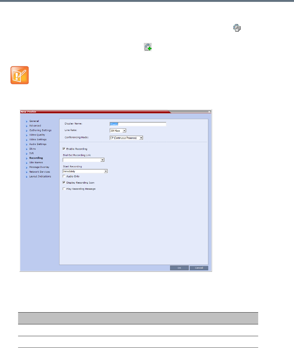
Recording and Streaming Conferences
Polycom, Inc. 459
To enable recording for a conference:
1In the Collaboration Server Management pane, click Conference Profiles ().
The Conference Profiles list is displayed.
2Create a new profile by clicking New Profile ( ), or modify an existing profile by double-clicking or
right-clicking an existing profile and then selecting Profile Properties.
3In the New Profile dialog box, click the Recording tab.
4Select the Enable Recording check box.
5Define the following parameters
If creating a new profile, complete the conference definition. For more information on creating Profiles
see Defining AVC CP Conferencing Profiles.
Conference Profile Recording Parameters
Parameter Description
Enable Recording Select to enable Recording Settings in the dialog box.
Recording Link Select a recording link for the conference from the list.
Recording and Streaming Conferences
Polycom, Inc. 460
6Click OK.
Recording is enabled in the Conference Profile.
Dial Out Recording Link Encryption
The Dial Out Recording Link can be encrypted when recording an encrypted conference. The encryption of
the Dial Out Recording Link is enabled when Encryption is selected in the Conference Profile on the
Collaboration Server and on the RealPresence Capture Server or RSS 4000 system, and the system flag
ALLOW_NON_ENCRYPT_RECORDING_LINK_IN_ENCRYPT_CONF is set to NO.
Dial Out Recording Link Encryption Guidelines:
●The Dial Out Recording Link connection type must be H.323.
●The Dial Out Recording Link uses the AES encryption format.
●The RealPresence Capture Server or RSS 4000 system recorder must be set to support encryption.
For more information see the RealPresence Capture Server or RSS 4000 system User Guide.
●Encryption must be selected in the Conference Profile.
Dial Out Recording Link Encryption Flag Setting
Dial Out Recording Links are treated as regular participants, however if the
ALLOW_NON_ENCRYPT_RECORDING_LINK_IN_ENCRYPT_CONF System Flag is set to YES a
non-encrypted Dial Out Recording Link is to be allowed to connect to an encrypted conference.
The following table summarizes the connection possibilities for a Dial Out Recording Link that is to be
connected to a conference for each of the conference profile and Entry Queue encryption options.
Start recording Select one of the following:
• Immediately – conference recording is automatically started upon
connection of the first participant.
• Upon Request – the operator or chairperson must initiate the
recording (manual).
Audio only Select this option to record only the audio channel of the conference.
Note: An Audio Only Recording Link cannot be used to record a
conference if there are no Voice resources allocated in the
Video/Voice Port Configuration.
Display Recording
Icon
Select this option to display Recording Indications to all conference
participants informing them that the conference is being recorded.
The recording icon is replaced by a Paused icon when conference
recording is paused.
For more information see New AVC CP Profile - Layout Indications
Parameters and Recording Indications
Play Recording
Message
Selected by default. A message is played to all participants
announcing that the conference is being recorded. Un check this box
to prevent the announcement from being played.
Conference Profile Recording Parameters
Parameter Description
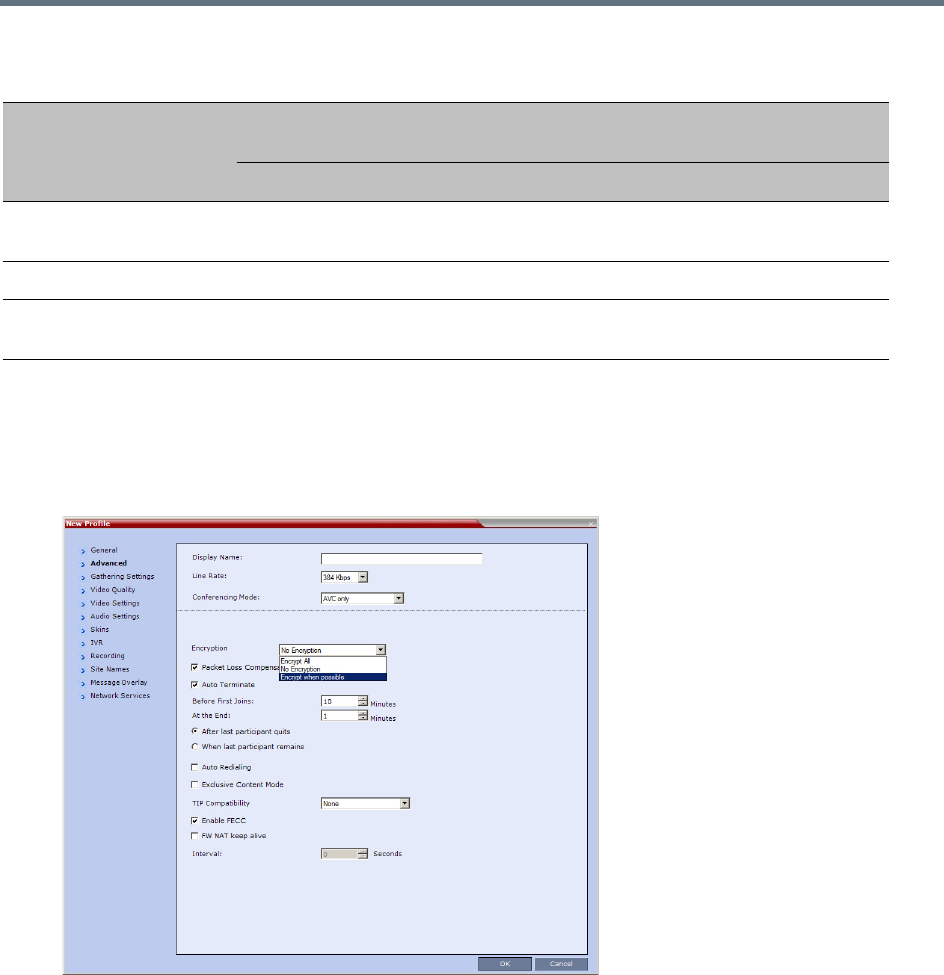
Recording and Streaming Conferences
Polycom, Inc. 461
Dial Out Recording Link Settings
The recording of encrypted conferences via an encrypted Dial Out Recording Link is enabled in the
Conference Profile by:
1Selecting the Encryption option (Encrypt All or Encrypt when Possible) in the Advanced tab.
For more details, see Packet Loss Compensation - LPR and DBA.
2Setting the Recording options in the Recording tab. For more details, see Enabling the Recording
in the Conference Profile.
Managing the Recording Process
When a conference is started and recording is enabled in its Profile, the system will automatically start the
recording if the Start Recording parameter is set to immediately. If it is set to Upon Request, the system waits
for the chairperson or Collaboration Server user’s request. Once the recording is initiated for a conference,
the MCU connects to the recording device (Capture Server). The connection that is created between the
Connections by Recording Link and Conference Encryption Settings
Conference Profile
Setting
Dial Out Recording Link Connection Status according to flag:
ALLOW_NON_ENCRYPT_RECORDING_LINK_IN_ENCRYPT_CONF
YES NO
Encrypt All Connected encrypted if possible,
otherwise connected non-encrypted.
Connected only if encrypted,
otherwise disconnected.
No Encryption Connected non-encrypted. Connected non-encrypted.
Encrypt when possible Connected encrypted if possible,
otherwise connected non-encrypted.
Connected encrypted if possible,
otherwise connected non-encrypted.
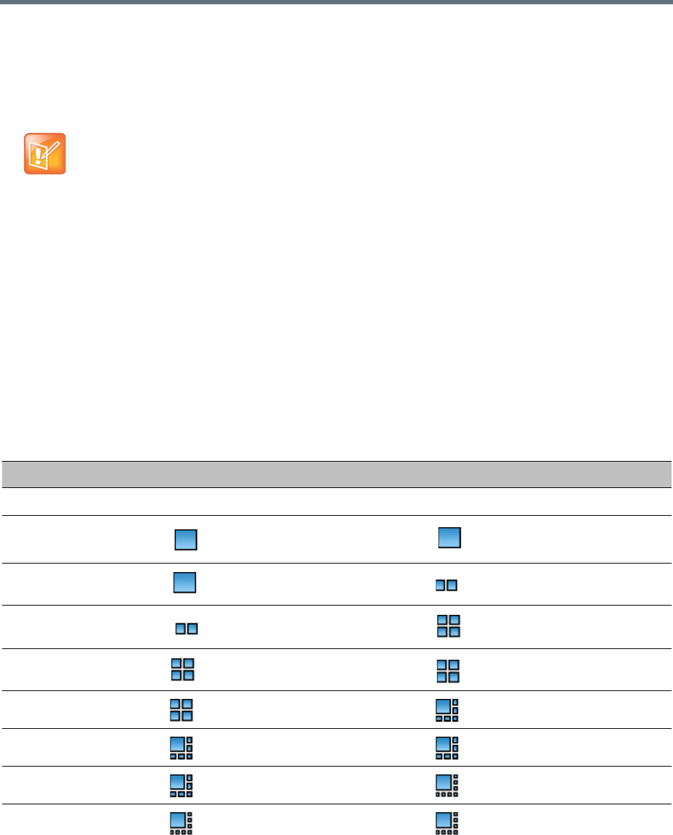
Recording and Streaming Conferences
Polycom, Inc. 462
conference and the recording device is represented as a special participant (Recording) whose name is the
Recording Link. Once the recording has started, the recording process can be stopped and restarted from
the Chairperson’s endpoint (using DTMF codes) or from the Collaboration Server Web Client. After the
recording process has finished, the recording can be identified in the Capture Server by its Collaboration
Server conference name.
Recording Layout
When the video layout of the conference is set to Auto Layout, the recording of the conference will now
include all the conference participants and not n-1 participants as in previous versions.
In the new Auto Layout algorithm, the Recording Link is counted as a participant, and therefore it is excluded
from the layout display used for the recording. The layout used for the other participants will behave as in
the standard Auto Layout behavior.
The Recording Layout can be changed during an ongoing conference in the same manner as for any other
conference participant. For more information see the Participant Level Monitoring.
The default settings for Auto Layout for the conference and the Recording Link are summarized in the
following table:
A conference participant and the Recording Link cannot have identical names, otherwise the
recording process will fail.
Recording Link Default Layout Settings (Auto Layout Mode)
Number of Participants Conference Default Auto Layout Settings Recording Link Auto Layout Settings
0N/A N/A
1
2
3
4
5
6
7
8
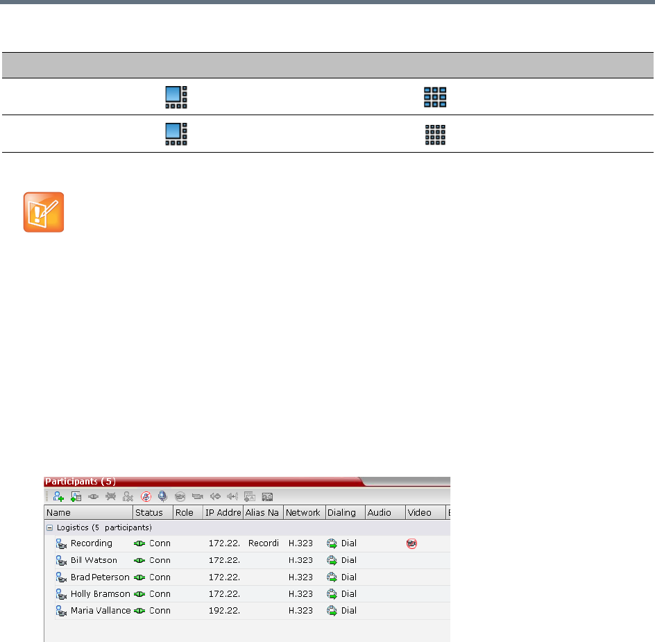
Recording and Streaming Conferences
Polycom, Inc. 463
The default settings for Auto Layout of the Recording Link cannot be changed, and the Auto Layout flags
do not apply to the Recording Link Auto Layout default settings.
Using the Collaboration Server Web Client to Manage the Recording
Process
To manage the recording process using the right-click menu:
»Right-click the Recording participant in the conference and select from one of the following options:
9
10 or more
When Capture Server dials in MCU for conference recording, you can choose the video layout from
the Capture Server Admin UI. The following layout is supported by Collaboration Server.
•Auto: automatic layout setting at the Collaboration Server side.
• Single View: record 1x1 layout.
•Dual View: record 1x2 layout.
Recording Link Default Layout Settings (Auto Layout Mode)
Number of Participants Conference Default Auto Layout Settings Recording Link Auto Layout Settings
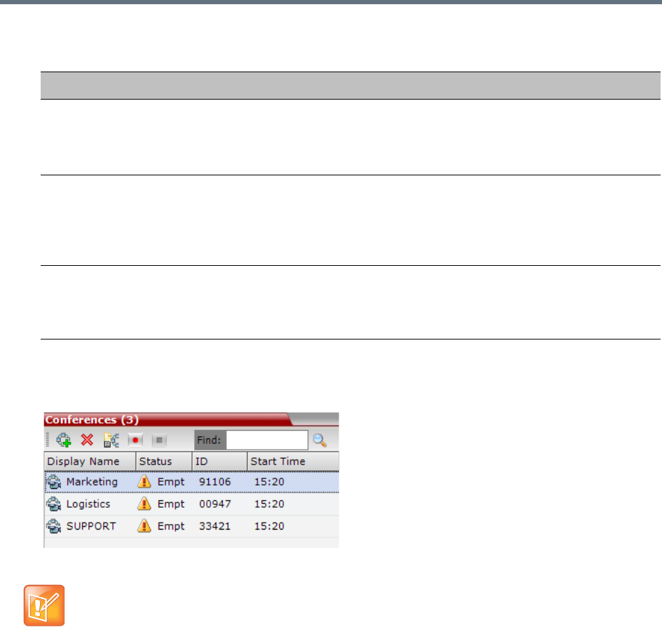
Recording and Streaming Conferences
Polycom, Inc. 464
To manage the recording process using the Conference toolbar:
»In the Conferences pane, click one of the following buttons in the Conference tool bar.
Recording Participant Right-click Options
Name Description
Suspend Video The Suspend Video option prevents the incoming video of the recording link
participant to be part of the conference layout.
The Recording Link participant is set by default to Suspend Video. The Suspend
Video option toggles with the Resume Video option.
Resume Video The Resume Video option enables the incoming video of the recording link
participant to be part of the conference layout.
This feature may be used to play back previously recorded video or audio feeds in
the conference layout. For more information, see the RealPresence Capture
Server or RSS 4000 system User Guide.
Participant Properties The Participant Properties option displays viewing only information for monitoring,
e.g. communication capabilities and channels used to connect to the conference.
Users will not be able to perform any functional requests from this window, i.e.
disconnect, change layout and mute.
The recording buttons will only be displayed in the conference tool bar for a conference that is
recording-enabled.
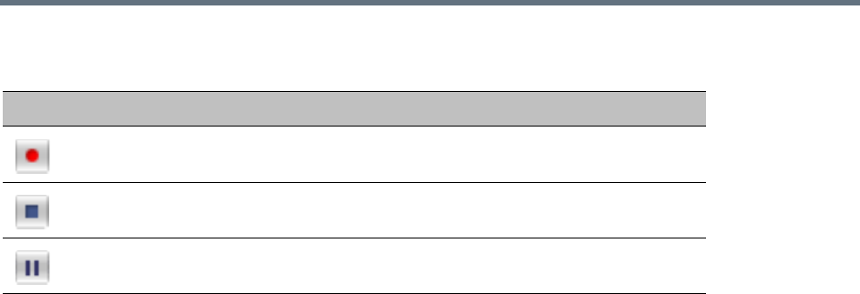
Recording and Streaming Conferences
Polycom, Inc. 465
Conferences List - Recording Tool bar buttons
Using DTMF Codes to Manage the Recording Process
By entering the appropriate DTMF code on the endpoint, the chairperson can Stop the recording (*3),
Pause it (*1), or Start/Resume the recording (*2). For more information on managing the recording process
via DTMF codes, see the RRealPresence Capture Server or RSS 4000 system User Guide.
Conference Recording with Codian IP VCR
Conference recording is available with Codian VCR 2210, VCR 2220 and VCR 2240.
Recording between the Collaboration Server and the Codian VCR is enabled by adding an IP participant to
the recorded conference that acts as a link between the conference and the recording device. This
participant is identified as a recording link to the Codian VCR according to the product ID sent from the VCR
during the connection phase, in the call setup parameters.
The video channel between the conference and the recording device is unidirectional where the video
stream is sent from the conference to the recorder.
If the Codian VCR opens a video channel to the conference - this channel is excluded from the conference
video mix.
To record a conference running on the Collaboration Server using Codian recorder:
»In the conference, define or add a dial-out participant using the Codian VCR IP address as the
address for dialing.
Once added to the conference, the MCU automatically connects the participant (the link to Codian VCR)
and the recording is automatically started on the Codian VCR.
A connection can also be defined on the Codian VCR, dialing into the recorded conference using the MCU
prefix and the Conference ID as for any other dial-in participant in the conference.
Monitoring the recording participant
This connection is monitored as any other participant in the conference. The connection can also be
monitored in the Codian VCR web client.
Button Description
Start/Resume recording. This button toggles with the Pause button.
Stop recording.
Pause recording. This button toggles with the Start/Resume button.

Polycom®, Inc. 466
Users, Connections, and Notes
Collaboration Server Users
Collaboration Server Web Client users are defined in the User’s table and can connect to the MCU to
perform various operations.
A maximum of 100 users can be defined per MCU.
User Types
The MCU supports the following user Authorization Levels:
Administrator
Operator
Machine Account (Application-user)
Administrator Read-only
Chairperson
Auditor
The authorization level determines a user’s capabilities within the system.
Administrator
An administrator can define and delete other users, and perform all configuration and maintenance tasks.
A default user with administrator authorization is provided by all MCU types to be used with Polycom
products, having the following details:
●User name - SA_PLCM_Integration
●Password - Polycom_CS
This user is not considered a new user. Therefore, no New SA_PLCM_Integration user message
should be generated.
The following user types are not supported in Ultra Secure Mode:
•SUPPORT user
•Chairperson
•Auditor
For more information see Ultra Secure Mode, User and Connection Management.
Users with Auditor authorization level cannot connect to the Collaboration Server via the RMX Manager
application and must use the Collaboration Server Web Client.

Users, Connections, and Notes
Polycom®, Inc. 467
Since this user is provided in secure mode (JITC) as well, an active alarm is displayed upon login, indicating
the existence of an SA_PLCM_Integration default user, and recommending replacing it with an alternate
one for security reasons.
This user should be recognized by the DMA/XMA as well, thus enable their logging into the MCU without
any undue messages, with the exception of the active alarm stated above upon logging into a secure
machine.
Administrator Read-only
A user with Administrator permission with the same viewing and monitoring permissions of a regular
Administrator. However, this user is limited to creating system backups and cannot perform any other
configuration or conference related operation.
Operator
An Operator can manage Meeting Rooms, Profiles, Entry Queues, and SIP Factories, and can also view
the Collaboration Server configurations, but cannot change them.
Administrator and Operator users can verify which users are defined in the system. Neither of them can view
the user passwords, but an Administrator can change a password.
Chairperson
A Chairperson can only manage ongoing conferences and participants. The Chairperson does not have
access to the Collaboration Server configurations and utilities.
Auditor
An Auditor can only view Auditor Files and audit the system.
Machine Account
User names can be associated with servers (machines) to ensure that all users are subject to the same
account and password policies. For more details, see Machine Account later on this chapter.
Listing Users
The Users pane lists the currently defined users in the system and their authorization levels. The pane also
enables the administrators to add and delete users.
The system is shipped with a default Administrator user called POLYCOM, whose password is POLYCOM.
However, once you have defined other authorized Administrator users, it is recommended to remove the
default user.
You can view the list of users that are currently defined in the system.
To view the users currently defined in the system:
1In the RMX Management pane, click Users ().
The Users pane is displayed.
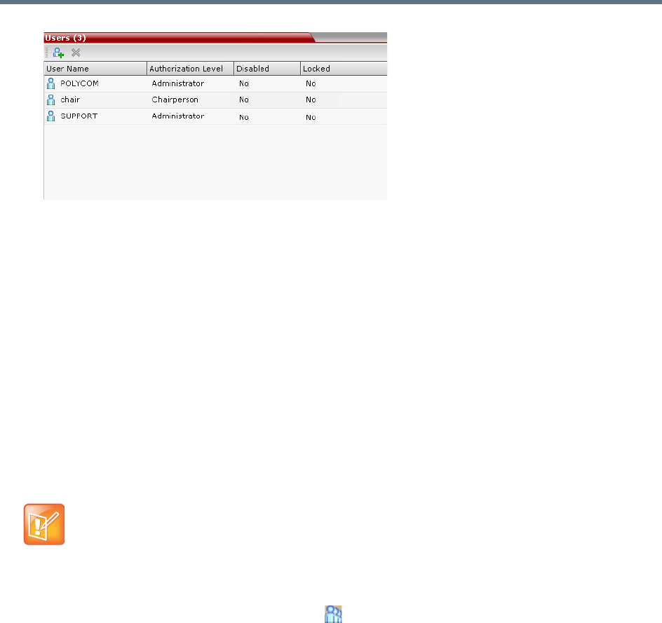
Users, Connections, and Notes
Polycom®, Inc. 468
The list includes three columns: User Name, Authorization Level and Disabled:
User Name - The login name used by the user to connect to the MCU.
The Authorization - Indicates the Authorization Level assigned to the User: Administrator,
Administrator Read-only, Operator, Chairperson or Auditor.
Disabled - Indicates whether the user is disabled and cannot access the system unless enabled
by the administrator. For more details, see Disabling a User.
Locked indicates whether the user has been locked out and cannot access the system unless
enabled by the administrator.
In Ultra Secure Mode (ULTRA_SECURE_MODE=YES), Users can be automatically disabled or
locked out by the system when they do not log into the Collaboration Server application for a
predefined period or if their login session does not meet Enhanced Security requirements. Users can
be manually disabled by the administrator. For more details, see Notes.
Adding a New User
Administrators can add new users to the system.
To add a new user to the system:
1In the RMX Management pane, click Users ().
2The Users pane is displayed.
The User Name and Password must be in ASCII.
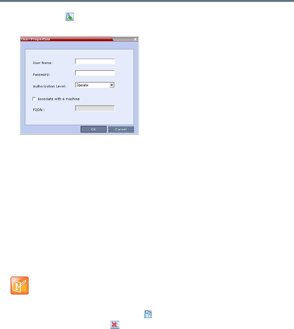
Users, Connections, and Notes
Polycom®, Inc. 469
3Click New User ( ), or right-click anywhere in the pane and then click New User.
The User Properties dialog box opens.
4In the User Name text box, enter the name of the new user. This is the login name used by the user
when logging into the system.
5In the Password text box, enter the new user’s password. This will be the user’s password when
logging into the system.
6In the Authorization Level list, select the user type: Administrator, Administrator Read-Only,
Operator, Chairperson or Auditor.
7To associate a user with a machine:
aIn the User Properties dialog box, select the Associate with a machine check box.
bEnter the FQDN of the server that hosts the application who’s application-user name is being
added.
8Click OK.
The User Properties dialog box closes and the new user is added to the system.
Deleting a User
1In the RMX Management pane, click Users ().
2Select the user and click Delete ( ), or right-click the user and then click Delete User.
The system displays a confirmation message.
3In the confirmation dialog box, select Yes to confirm or No to cancel the operation.
If you select Yes, the user name and icon are removed from the system.
To delete a user, you must have Administrator authorization. The last remaining Administrator in the
Users list cannot be deleted.

Users, Connections, and Notes
Polycom®, Inc. 470
Changing a User’s Password
Users with Administrator authorization can change their own password and other users’ passwords. Users
with Operator authorization can change their own password.
To change a user’s password:
1In the RMX Management pane, click Users ().
2Right-click the user and click Change User Password.
The Change Password dialog box opens.
3Enter the Old Password (current), New Password and Confirm the New Password.
4Click OK.
The user’s password is changed.
Disabling a User
An administrator can disable an enabled user. An indication is displayed in the Users List when the User is
disabled. An administrator can enable a disabled User.
To disable a user:
1In the RMX Management pane, click Users ().
The Users pane is displayed.
2In the Users pane, right-click the user to be disabled and select Disable User in the menu.
A confirmation box is displayed.
3Click YES.
The User status in the Users list - Disabled column changes to Yes.
Enabling a User
An administrator can enable a User who was disabled automatically by the system (in the Ultra Secure
Mode) or manually by the administrator.
The Password must be in ASCII.
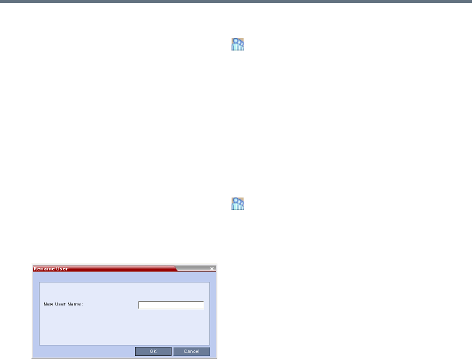
Users, Connections, and Notes
Polycom®, Inc. 471
To enable a user:
1In the RMX Management pane, click Users ().
The Users pane is displayed.
2Right-click the user to be enabled and select Enable User.
A confirmation box is displayed.
3Click YES.
The User status in the Users list - Disabled column changes to NO.
Renaming a User
To rename a user:
1In the RMX Management pane, click Users ().
The Users pane is displayed.
2Right-click the user to be renamed and select Rename User.
The Rename User dialog box is displayed.
3Enter the user’s new name in the New User Name field and click OK.
The user is renamed and is forced to change his/her password.
Machine Account
User names can be associated with servers (machines) to ensure that all users are subject to the same
account and password policies.
For enhanced security reasons it is necessary for the Collaboration Server to process user connection
requests in the same manner, whether they be from regular users accessing the Collaboration Server via
the Collaboration Server Web Browser / RMX Manager.
Regular users can connect from any workstation having a valid certificate while application-users
representing applications can only connect from specific servers. This policy ensures that a regular user
cannot impersonate an application-user to gain access to the Collaboration Server in order to initiate an
attack that would result in a Denial of Service (DoS) to the impersonated application.
The connection process for an application-user connecting to the Collaboration Server is as follows:
1The application-user sends a connection request, including its TLS certificate, to the Collaboration
Server.
2The Collaboration Server searches its records to find the FQDN that is associated with the
application-user’s name.

Users, Connections, and Notes
Polycom®, Inc. 472
3If the FQDN in the received certificate matches that associated with application-user, and the
password is correct, the connection proceeds.
Guidelines for defining a machine account
●Application-users are only supported when TLS security is enabled and Request peer certificate is
selected. TLS security cannot be disabled until all application-user accounts have been deleted from
the system.
●For Secure Communications, an administrator must set up on the Collaboration Server system a
machine account for the RealPresence DMA system with which it interacts. This machine account
must include a fully-qualified domain name (FQDN) for the RealPresence DMA system.
●Application-user names are the same as regular user names.
Example: the DMA application could have an application-user name of DMA1.
●The FQDN can be used to associate all user types: Administrator, Operator with the FQDN of a
server.
●Multiple application-users can be configured the same FQDN name if multiple applications are
hosted on the same server
●If the system is downgraded the application-user’s FQDN information is not deleted from the
Collaboration Server’s user records.
●A System Flag, PASS_EXP_DAYS_MACHINE, enables the administrator to change the password
expiration period of application-user’s independently of regular users. The default flag value is 365
days.
●The server hosting an application-user whose password is about to expire will receive a login
response stating the number of days until the application-user’s password expires. This is determined
by the value of the PASSWORD_EXPIRATION_WARNING_DAYS System Flag. The earliest
warning can be displayed 14 days before the password is due to expire and the latest warning can
be displayed 7 days before passwords are due to expire. An Active Alarm is created stating the
number of days before the password is due to expire.
●The MIN_PWD_CHANGE_FREQUENCY_IN_DAYS System Flag does not effect application-user
accounts. Applications typically manage their own password change frequency.
●If an application-user identifies itself with an incorrect FQDN, its account will not be locked, however
the event is written to the Auditor Event File.
●If an application-user identifies itself with a correct FQDN and an incorrect password, its account will
be locked and the event written to the Auditor Event File.
●An application-user cannot be the last administrator in the system. The last administrator must be
regular user.
●User names are not case sensitive.
Monitoring
●An application-user and its connection is represented by a specific icon.
Active Directory
●When working with Active Directory, the RealPresence DMA system cannot be registered within
Active Directory as regular users. The RealPresence DMA system application-users must be
manually.
●The only restriction is that TLS mode is enabled together with client certificate validation.
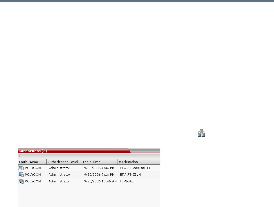
Users, Connections, and Notes
Polycom®, Inc. 473
●If the above configuration are set off it will not be possible to add machine accounts.
●When setting the TLS mode off the system should check the existence of a machine account and
block this operation until all machine accounts are removed.
Connections
The Collaboration Server enables you to list all connections that are currently logged into the MCU, e.g.
users, servers or API users. The MCU issues an ID number for each login. The ID numbers are reset
whenever the MCU is reset.
A maximum of 50 users can be concurrently logged in to the MCU.
Viewing the Connections List
To list the users who are currently connected to the MCU:
1In the Collaboration Server Management pane, click Connections ().
A list of connected users is displayed in the Connections pane.
The information includes:
The user’s login name.
The user’s authorization level (Chairperson, Operator, Administrator or Auditor).
The time the user logged in.
The name/identification of the computer used for the user’s connection.
Notes
Notes are the electronic equivalent of paper sticky notes. You can use notes to write down questions,
important phone numbers, names of contact persons, ideas, reminders, and anything you would write on
note paper. Notes can be left open on the screen while you work.
Using Notes
Notes can be read by all system Users concurrently connected to the MCU. Notes that are added to the
Notes list are updated on all workstations by closing and re-opening the Notes window. Notes can be written
in any Unicode language.
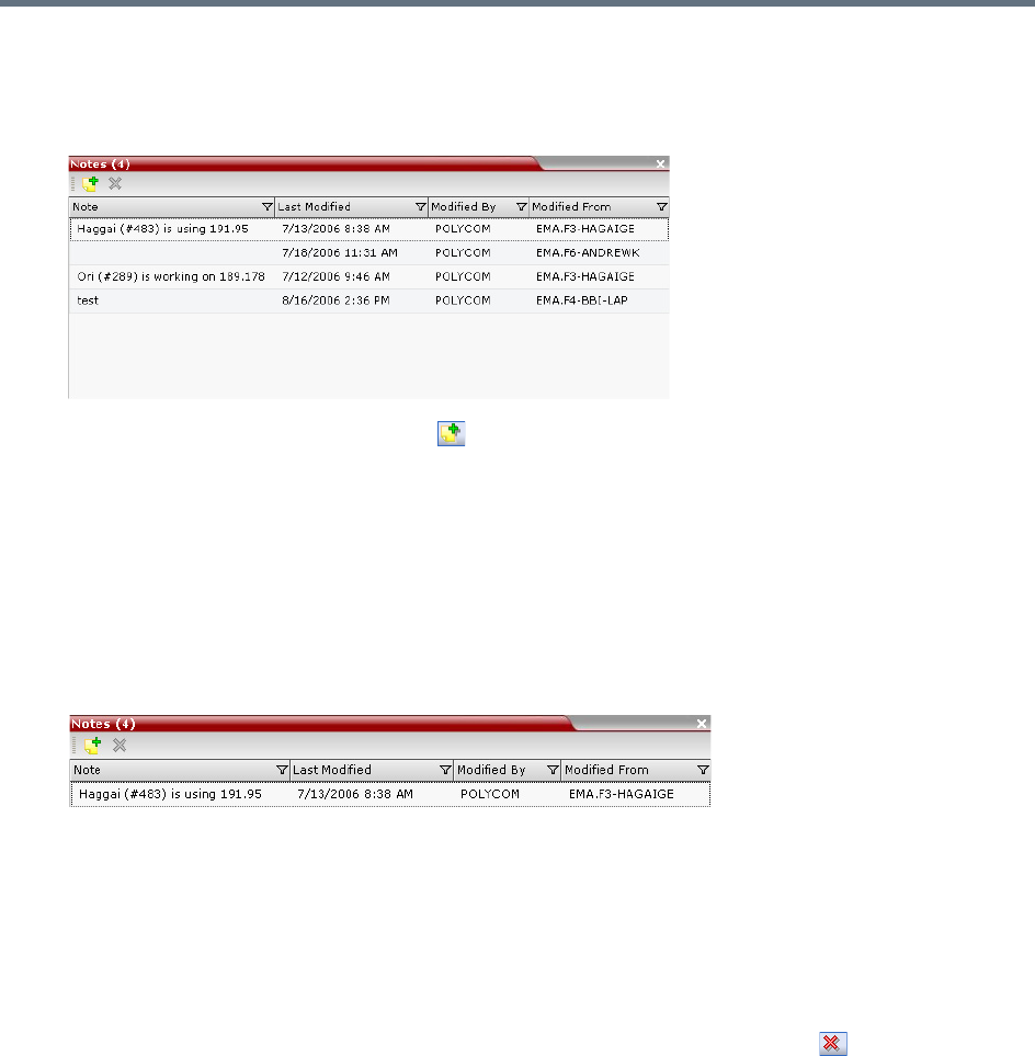
Users, Connections, and Notes
Polycom®, Inc. 474
To create a note:
1On the Collaboration Server menu, select Administration > Notes.
The Notes window opens.
2In the Notes toolbar, click New Note ( ), or right-click anywhere inside the Notes window and
select New Note.
3In the Note dialog box, type the required text and click OK.
The new note is saved and closed. The Notes list is updated, listing the new note and its properties:
Note – The beginning of the note’s text.
Last Modified – The date of creation or last modification.
Modified By – The Login Name of the user who last modified the note.
Modified From – The Client Application and Workstation from which the note was created or
modified.
To open or edit a note:
»Double-click the entry to edit, or right-click the entry and select Note Properties.
The note opens for viewing or editing.
To delete a note:
1In the Notes list, select the entry for the note to delete and click Delete Note ( ), or right-click the
entry and select Delete Note.
A delete confirmation dialog box is displayed.
2Click OK to delete the note, or click Cancel to keep the note.

Polycom, Inc. 475
IP Network Services
IP Network Services enable the Collaboration Server to function within IP network environments. They
include the network parameters required for the MCU to connect with other IP devices on the same network
or outside the network through a firewall.
Collaboration Server IP Network Services Overview
Two types of IP Network Services are defined for the Collaboration Server:
●Management Network Service
●Default IP Service (Conferencing Service)
Connection between the Collaboration Server management applications (Web Client And RMX Manager)
and participant connections to conferences (Dial in, dial out) are supported within the following IP
addressing environments: IPv4, IPv6 and IPv6 & IPv4
When IPv4 is selected, IPv6 fields are hidden and conversely when IPv6 is selected, IPv4 fields are hidden.
When IPv6 & IPv4 is selected both IPv6 and IPv4 fields are displayed.
For more information on IPv6, see LAN Redundancy.
When the RMX is configured for IPv4 and IPv6 Addressing, the addition of the sdp-anat option tag in the
SIP Require and SIP Supported headers allows a mixture of IPv4 and IPv6 addressing to be specified by
the Session Description Protocol (SDP). For more information see Management Network (Primary).
For the purposes of comprehensive documentation, all screen captures in this chapter pertaining to
RealPresence Collaboration Servers (RMX) 1500/1800/2000/4000 show the dialog boxes as
displayed with IPv6 & IPv4 selected.
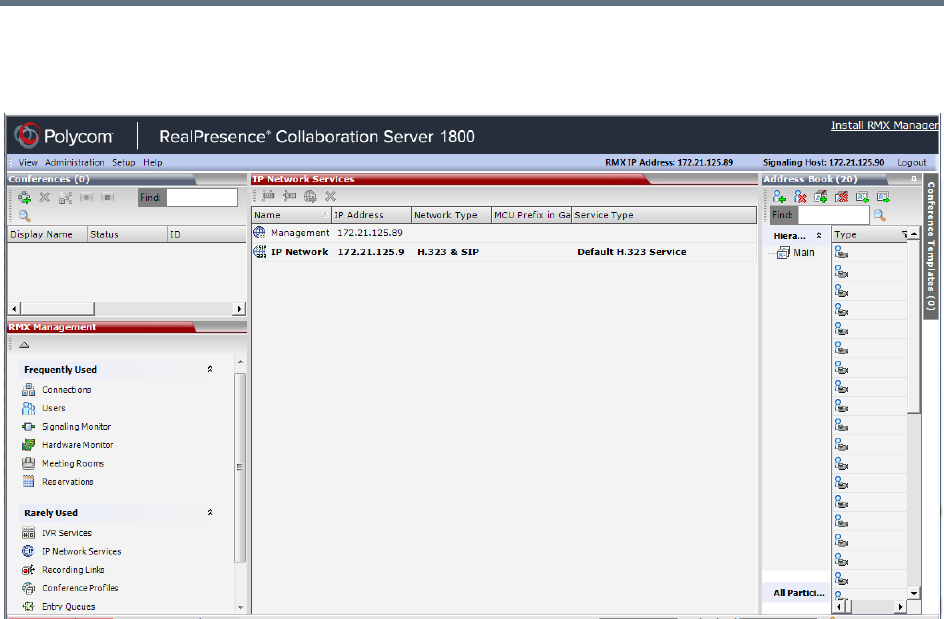
IP Network Services
Polycom, Inc. 476
The IP Network Services are configured by selecting this option in the RMX Management pane of the
Collaboration Server Web Client/RMX Manager application.
Management Network (Primary)
The Management Network is used to connect between the Collaboration Server and the management
applications (Collaboration Server Web Client or RMX Manager application) and enable these applications
to control the MCU. It contains the network parameters, such as the IP address of the MCU’s control unit,
required for connection between the Collaboration Server and the management applications. You can use
this IP address to connect to the control unit should the MCU become corrupted or inaccessible.
During First Time Power-up, the Management Network parameters can be set either via a USB key or by
using a cable to create a private network. For more information, see First Entry Power-up and Configuration
and Appendix G - Configuring Direct Connections to the Collaboration Server in the RealPresence
Collaboration Server (RMX) Getting Started Guide.
Default IP Service (Conferencing Service)
The Default IP Service (Conferencing Service) is used to configure and manage communications between
the Collaboration Server and conferencing devices such as endpoints, gatekeepers, SIP servers, etc.
The Default IP Service contains parameters for:
●Signaling Host IP Address
●External conferencing devices
Calls from all external IP entities are made to the Signaling Host, which initiates call set-up and assigns the
call to the appropriate media card.
Conferencing related definitions such as environment (H.323 or SIP) are also defined in this service.

IP Network Services
Polycom, Inc. 477
Most of the Default IP Service is configured by the Fast Configuration Wizard, which runs automatically
should the following occur:
●First time power-up.
●Deletion of the Default IP Service, followed by a system reset.
For more information, see First Entry Power-up and Configuration in the Polycom® RealPresence
Collaboration Server (RMX) 1500/1800/2000/4000 Getting Started Guide
Using IPv6 Networking Addresses for Collaboration Server Internal
and External Entities
IPv6 addresses can be assigned to both Collaboration Server (Internal) and External Entity addresses.
Collaboration Server Internal Addresses (Default Management Network Service):
●Control Unit
●Signaling Host
●Shelf Management
●MPM1 (Media Card)
●MPM2 (Media Card)
External Entities:
●Gatekeepers (Primary & Secondary)
●SIP Proxies on EMA
●DNS Servers
●Default Router
●Defined participants
IPv6 Addressing Guidelines
●Internet Explorer 7™ is required for the Collaboration Server Web Client and RMX Manager to
connect to the Collaboration Server using IPv6.
●The default IP address version is IPv4.
●The IP address field in the Address Book entry for a defined participant can be either IPv4 or IPv6. A
participant with an IPv4 address cannot be added to an ongoing conference while the Collaboration
Server is in IPv6 mode nor can a participant with an IPv6 address be added while the Collaboration
Server is in IPv4 mode.
An error message, Bad IP address version, is displayed and the New Participant dialog box remains
open so that the participant’s address can be entered in the correct format.
●Participants that do not use the same IP address version as the Collaboration Server in ongoing
conferences launched from Meeting Rooms, Reservations and Conference Templates, and are
disconnected. An error message, Bad IP address version, is displayed.
●IP Security Protocols (IPSec) are not supported.
Changes made to any of these parameters only take effect when the Collaboration Server is reset.
An Active Alarm is created when changes made to the system have not yet been implemented and
the MCU must be reset.
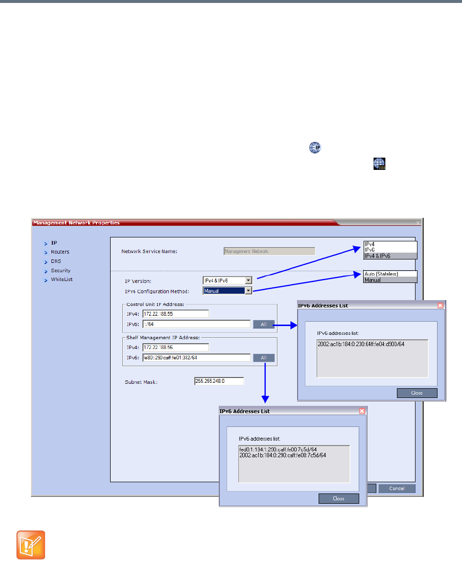
IP Network Services
Polycom, Inc. 478
Modifying the Management Network
The Management Network parameters need to be modified if you want to:
●Connect directly to the Collaboration Server from a workstation
●Modify routes
●Modify DNS information
To view or modify the Management Network Service:
1In the RMX Management pane, click the IP Network Services () button.
2In the IP Network Services list pane, double-click the Management Network ( ) entry.
The Management Network Properties - IP dialog box opens
Management Network Properties - Collaboration Servers (RMX) 1500/2000/4000
On the RealPresence Collaboration Server (RMX) 2000 an additional tab called LAN Ports appears.
For more information on the LAN Ports tab see Step 8.
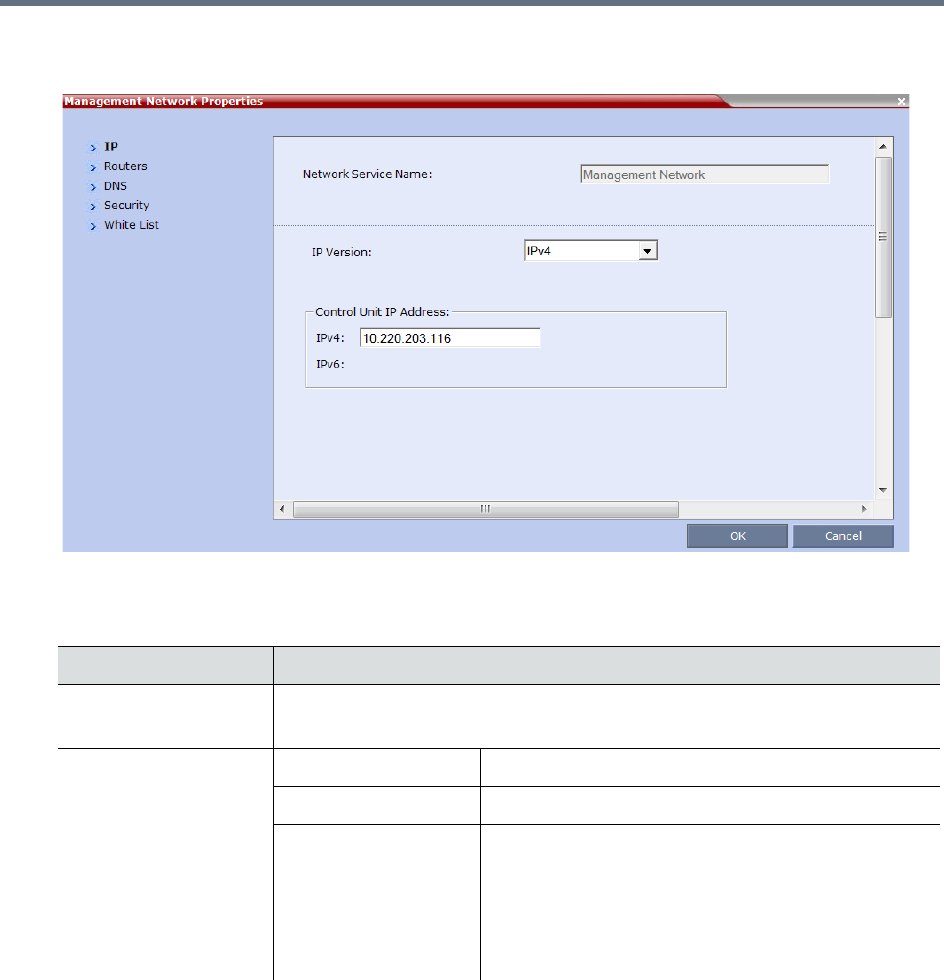
IP Network Services
Polycom, Inc. 479
Management Network Properties - Collaboration Server (RMX) 1800
3Modify the following fields:
Default Management Network Service – IP
Field Description
Network Service Name Displays the name of the Management Network. This name cannot be modified.
Note: This field is displayed in all Management Network Properties tabs.
IP Version IPv4 Select this option for IPv4 addressing only.
IPv6 Select this option for IPv6 addressing only.
IPv4 & IPv6 Select this option for both IPv4 and IPv6 addressing.
Note: If the gatekeeper cannot operate in IPv6
addressing mode, the H323_RAS_IPV6 System Flag
should be set to NO.
For more information see Manually Adding Flags to the
CS_MODULE_PARAMETERS Tab.

IP Network Services
Polycom, Inc. 480
IPv6 Configuration
Method
Manual Configuration
Method is
recommended with
IPv6.
Auto (Stateless) Select this option to allow automatic generation of the
following addresses:
•Link-Local (For internal use only)
•Site-Local
•Global
Manual Select this option to enable manual entry of the
following addresses:
•Site-Local
•Global
Manual configuration of the following address types is
not permitted:
•Link-Local
•Multicast
•Anycast
Control Unit IP Address IPv4 The IPv4 address of the Collaboration Server. This IP
address is used by the Collaboration Server Web
Client to connect to the Collaboration Server.
IPv6 The IPv6 address of the MCU. This IP address is used
by the Collaboration Server Web Client to connect to
the Collaboration Server.
Note: Internet Explorer 7™ is required for the
Collaboration Server Web Client to connect to the
MCU using IPv6.
All Click the All button to display the IPv6
addresses as follows:
•Auto - If selected, Site-Local and Global
site addresses are displayed.
•Manual - If selected, only the Manual site
address is displayed.
Default Management Network Service – IP
Field Description
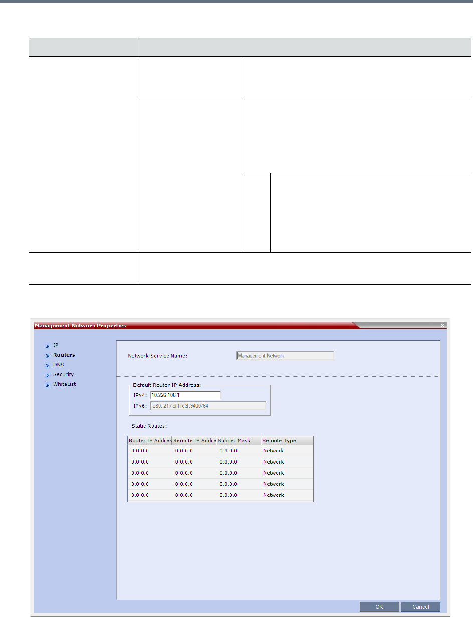
IP Network Services
Polycom, Inc. 481
4Click the Routers tab.
Shelf Management IP
Address
Collaboration Server
1500/2000/4000 only)
IPv4 The IPv4 address of the RMX Shelf Management
Server. This IP address is used by the Collaboration
Server Web Client for Hardware Monitoring purposes.
IPv6 The IPv6 address of the RMX Shelf Management
Server. This IP address is used by the Collaboration
Server Web Client for Hardware Monitoring purposes.
Note: Internet Explorer 7™ is required for the
Collaboration Server Web Client to connect to the
MCU using IPv6.
All Click the All button to display the IPv6
addresses as follows:
•Auto - If selected, Site-Local and Global
site addresses are displayed.
•Manual - If selected, only the Manual site
address is displayed.
Subnet Mask Enter the subnet mask of the Control Unit.
Note: This field is specific to IPv4 and is not displayed in IPv6 only mode.
Default Management Network Service – IP
Field Description
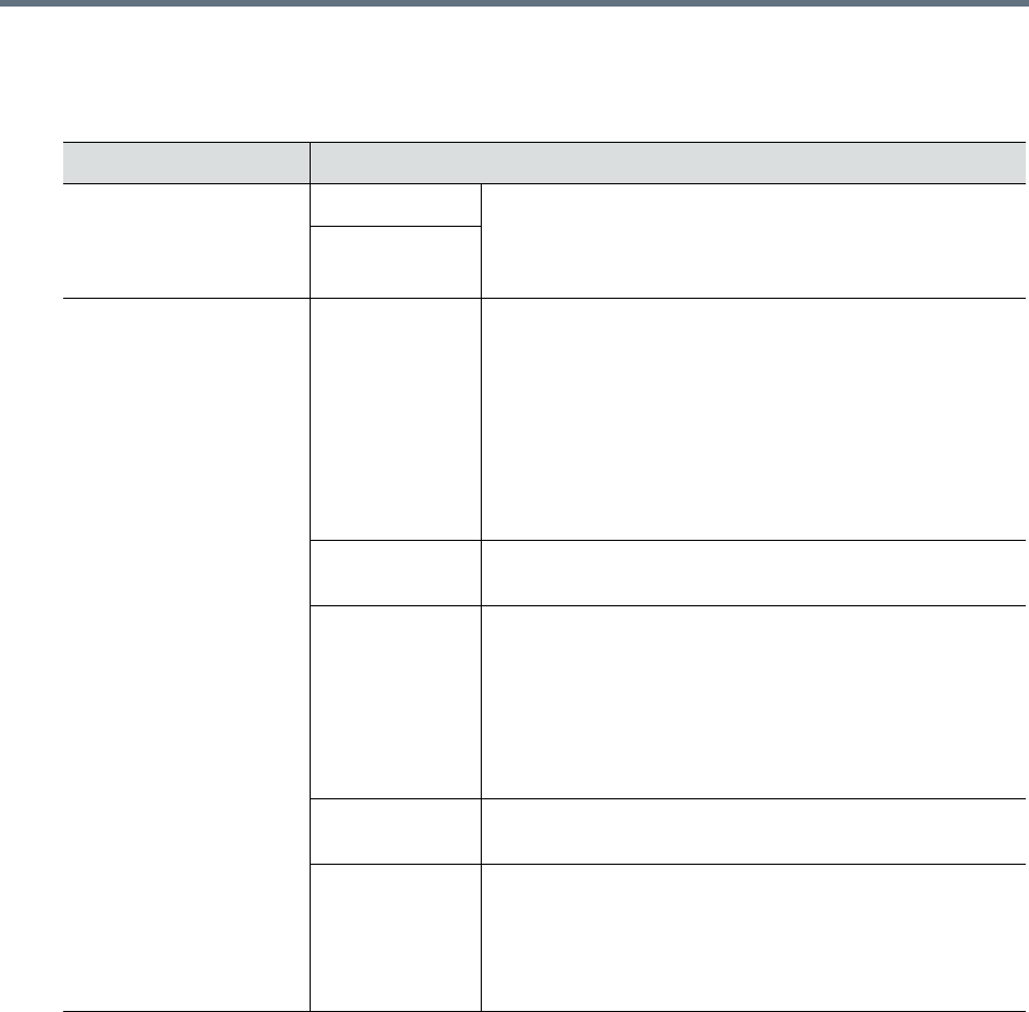
IP Network Services
Polycom, Inc. 482
5Modify the following fields:
Default Management Network Service – Routers
Field Description
Default Router IP
Address
IPv4 Enter the IP address of the default router. The default router
is used whenever the defined static routers are not able to
route packets to their destination. The default router is also
used when host access is restricted to one default router.
IPv6
Static Routes
(IPv4 Only Table)
The system uses Static Routes to search other networks
for endpoint addresses that are not found on the local LAN.
Up to five routers can be defined in addition to the Default
Router. The order in which the routers appear in the list
determines the order in which the system looks for the
endpoints on the various networks. If the address is in the
local subnet, no router is used.
To define a static route (starting with the first), click the
appropriate column and enter the required value.
Router IP
Address
Enter the IP address of the router.
Remote IP
Address
Enter the IP address of the entity to be reached outside the
local network. The Remote Type determines whether this
entity is a specific component (Host) or a network.
•If Host is selected in the Remote Type field, enter the IP
address of the endpoint.
•If Network is selected in the Remote Type field, enter of
the segment of the other network.
Remote Subnet
Mask
Enter the subnet mask of the remote network.
Remote Type Select the type of router connection:
•Network – defines a connection to a router segment in
another network.
•Host – defines a direct connection to an endpoint found
on another network.
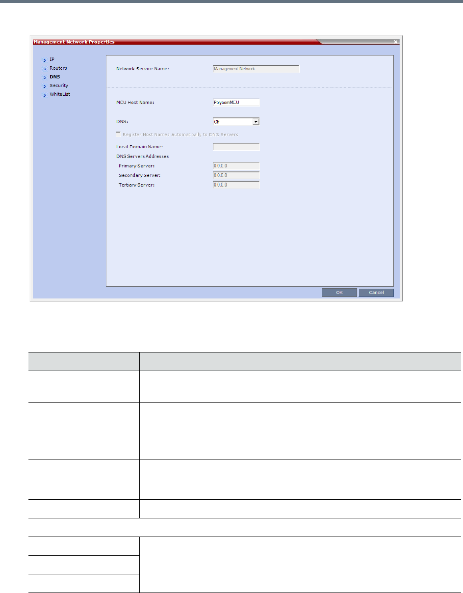
IP Network Services
Polycom, Inc. 483
6Click the DNS tab.
7Modify the following fields:
Default Management Network Service – DNS
Field Description
MCU Host Name Enter the name of the MCU on the network.
Default name is RMX
DNS Select:
•Off – If DNS servers are not used in the network.
•Specify –To enter the IP addresses of the DNS servers.
Note: The IP address fields are enabled only if Specify is selected.
Register Host Names
Automatically to DNS
Servers
Select this option to automatically register the MCU Signaling Host and Shelf
Management with the DNS server.
Local Domain Name Enter the name of the domain where the MCU is installed.
DNS Servers Addresses
Primary Server The static IP addresses of the DNS servers.
A maximum of three servers can be defined.
Secondary Server
Tertiary Server
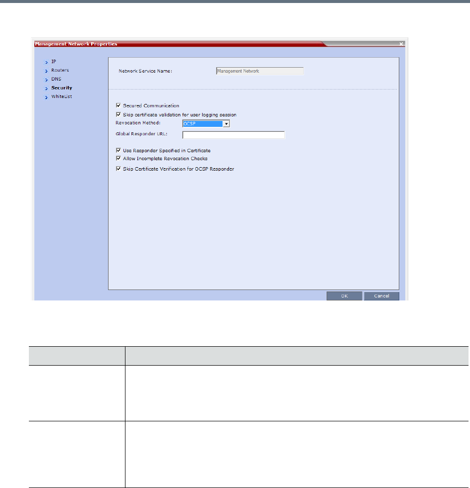
IP Network Services
Polycom, Inc. 484
8Click the Security tab.
9Modify the following fields:
Management Network Properties – Security Parameters
Field Description
Secured
Communication
Select to enable Secured Communication.
The Collaboration Server supports TLS 1.0 and SSL 3.0 (Secure Socket Layer).
A SSL/TLS Certificate must installed on the Collaboration Server for this feature to
be enabled. For more information see Appendix F- Secure Communication Mode.
Skip certificate
validation for user
logging session
Select this check box to prevent peer certificate requests being issued.
For more information see (PKI) Public Key Infrastructure.
This check box must be cleared when enabling Secured Mode. If it is not cleared
an Active Alarm is created and a message is displayed stating that Secured
Communications Mode must be enabled.
Revocation Method

IP Network Services
Polycom, Inc. 485
10 Click OK.
11 If you have modified the Management Network Properties, reset the MCU.
12 To define a white list, click the White List tab.
A White List contains the addresses of IP Networking Entities permitted to connect to the RMX’s
Management Network; Networking Entities such as Network Hosts, Control Workstations,
Gatekeepers SIP/ DNS Servers, etc.
For a detailed description of these fields see White List Access.
Global Responder
URL
For a detailed description of these fields see Certificate Managementand Certificate
Revocation.
Use Responder
Specified in
Certificate
Allow Incomplete
Revocation Checks
Skip Certificate
Validation for OSCP
Responder
For a detailed description see Certificate Management and Certificate Revocation.
Management Network Properties – Security Parameters
Field Description
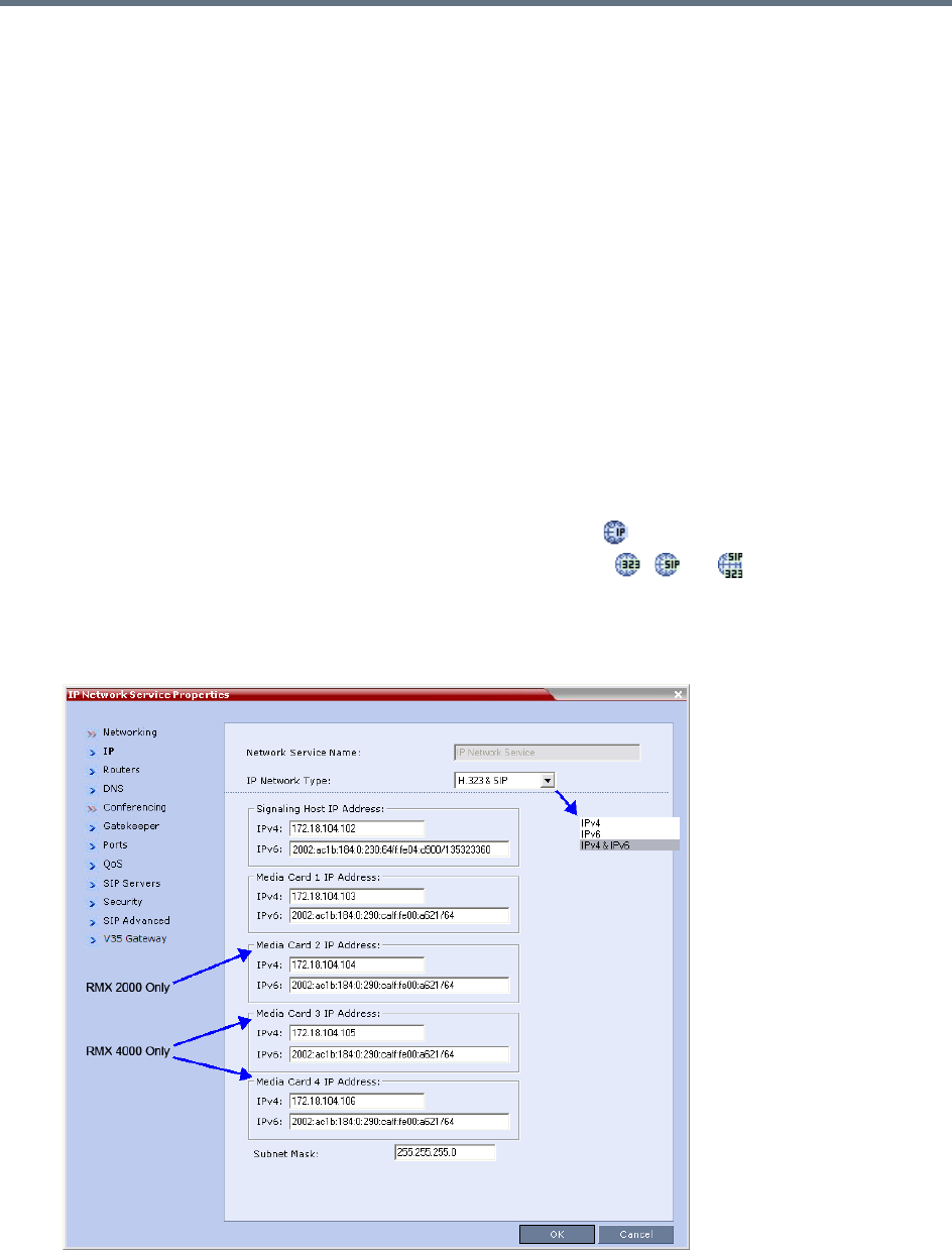
IP Network Services
Polycom, Inc. 486
Modifying the Default IP Network Service
The Default IP Network Service is defined initially during the First Time Power-up or if the Default IP Service
has been deleted, followed by an Collaboration Server restart. For details, see Polycom® RealPresence
Collaboration Server (RMX) 1500/1800/2000/4000 Getting Started Guide, Procedure 4: Modifying the
Default IP Service and ISDN/PSTN Network Service Settings.
Once the Default IP Network Service is defined, you can modify its properties through the IP Network
Properties dialog boxes. The Default IP Service parameters need to be modified if you want to change the:
●Network type that the Collaboration Server connects to
●IP address of the Collaboration Server Signaling Host
●IP addresses of the Collaboration Server Media boards
●Subnet mask of the Collaboration Server’s IP cards
●Gatekeeper parameters or add gatekeepers to the Alternate Gatekeepers list
●SIP server parameters
To view or modify the Default IP Service:
1In the RMX Management pane, click IP Network Services ().
2In the Network list pane, double-click the Default IP Service ( , , or ) entry.
The Default IP Service - Networking IP dialog box is displayed.
Default IP Service - Collaboration Servers (RMX) 1500/2000/4000
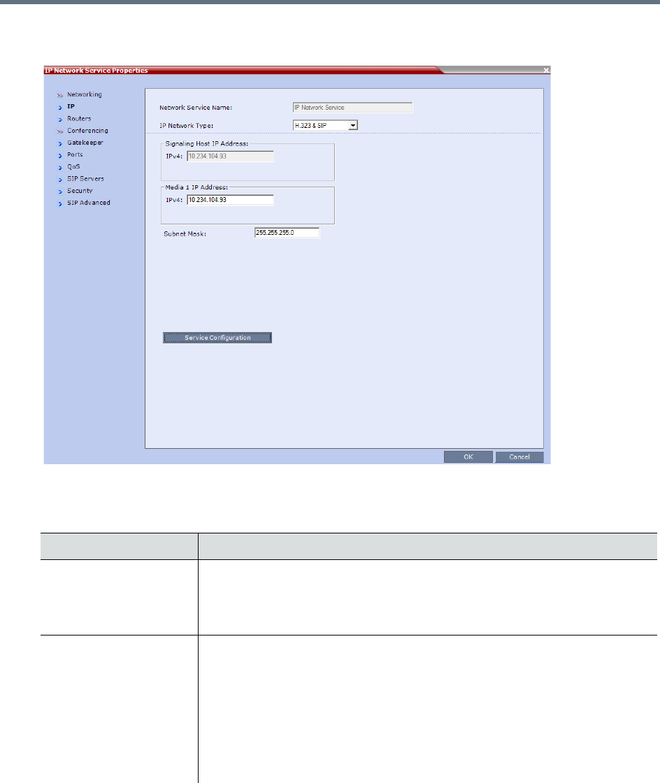
IP Network Services
Polycom, Inc. 487
Default IP Service - Collaboration Server (RMX) 1800
3Modify the following fields:
Default IP Network Service – IP
Field Description
Network Service Name The name Default IP Service is assigned to the IP Network Service by the Fast
Configuration Wizard. This name can be changed.
Note: This field is displayed in all IP Signaling dialog boxes and can contain
character sets that use Unicode encoding.
IP Network Type Displays the network type selected during the First Entry configuration. The
Default IP Network icon indicates the selected environment.
You can select:
• H.323 - For an H.323-only Network Service.
• SIP - For a SIP-only Network Service.
• H.323 & SIP - For an integrated IP Service. Both H.323 and SIP participants
can connect to the MCU using this service.
Note: This field is displayed in all Default IP Service tabs.
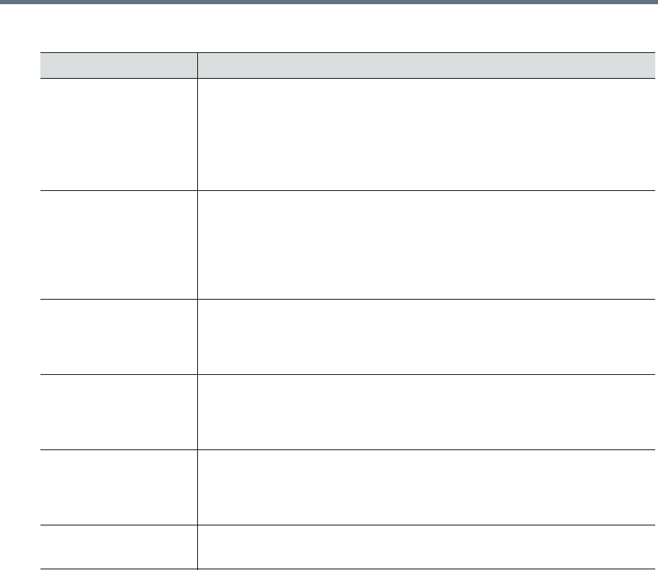
IP Network Services
Polycom, Inc. 488
Signaling Host IP
Address
On RealPresence Collaboration Server 1800 this field is disabled as only one IP
address is used for signaling and media transmission.
Enter the address to be used by IP endpoints when dialing in to the MCU.
Dial out calls from the Collaboration Server are initiated from this address.
This address is used to register the Collaboration Server with a Gatekeeper or a
SIP Proxy server.
Media Card 1 IP Address Collaboration Server 1500/1800: Enter the IP address of the media card to be
used by IP endpoints when dialing in to the MCU.
Collaboration Server 2000/4000: Enter the IP address of the first media card
as provided by the network administrator.first media card
Endpoints connect to conferences and transmit call media (video, voice and
content) via these addresses.
Media Card 2 IP Address
(Collaboration Server
2000/4000)
Collaboration Server 2000/4000: Enter the IP address of the second media
card if installed.
Endpoints connect to conferences and transmit call media (video, voice and
content) via these address.
Media Card 3 IP Address
(Collaboration Server
4000)
Collaboration Server 4000: Enter the IP address of the third media cards if
installed.
Endpoints connect to conferences and transmit call media (video, voice and
content) via these addresses.
Media Card 4 IP Address
(Collaboration Server
4000)
Collaboration Server 4000: Enter the IP address of the fourth media cards if
installed.
Endpoints connect to conferences and transmit call media (video, voice and
content) via these addresses.
Subnet Mask Enter the subnet mask of the MCU.
Default value: 255.255.255.0.
Default IP Network Service – IP
Field Description
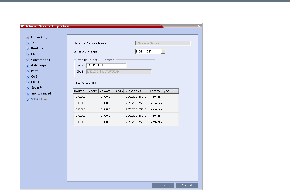
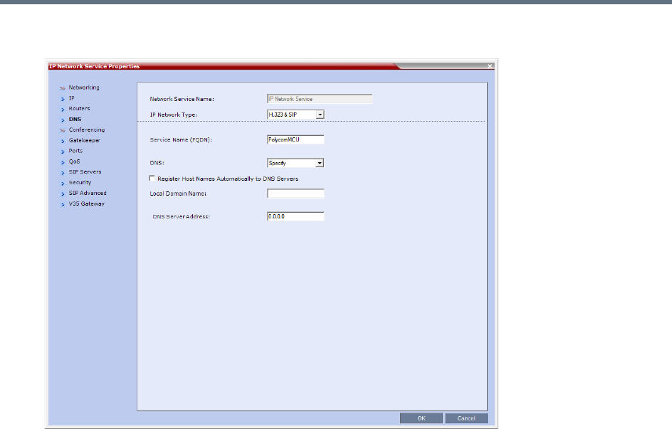
IP Network Services
Polycom, Inc. 490
5 Optional. Click the DNS tab.
6In the DNS field select Specify.
7In the DNS Server Address field, enter the IP address of the DNS Server for the IP Network
Service.
If the DNS field in the IP Network Service is set to Specify and the DNS is not configured or
disabled, the DNS configured for the Management Network will be used.
When upgrading from a version that does not support a DNS per IP Network Service, the DNS
configured for the Management Network will be used.
In both Standard Security and Ultra Secure Modes:
A separate DNS can be configured for the Management Network Service and the IP Network
Service.
If a Multiple Services Licence is installed, a separate DNS can be configured for each
additional IP Network Service that is defined. For more information see Multiple Network
Services.
IP Network Services
Polycom, Inc. 491
8To view or modify the gatekeeper parameters, click the Gatekeeper tab.
9 Modify the following fields:
Default IP Service – Conferencing – Gatekeeper Parameters
Field Description
Gatekeeper Select Specify to enable configuration of the gatekeeper IP address.
When Off is selected, all gatekeeper options are disabled.
Primary Gatekeeper IP
Address or Name
Enter either the gatekeeper’s host name as registered in
the DNS or IP address.
Note: When in
IPv4&IPv6 or in
IPv6 mode, it is
easier to use
Names instead of
IP Addresses.
Alternate Gatekeeper IP
Address or Name
Enter the DNS host name or IP address of the gatekeeper
used as a fallback gatekeeper used when the primary
gatekeeper is not functioning properly.
MCU Prefix in
Gatekeeper
Enter the number with which this Network Service registers in the gatekeeper.
This number is used by H.323 endpoints as the first part of their dial-in string
when dialing the MCU.
When PathNavigator or SE200 is used, this prefix automatically registers with
the gatekeeper. When another gatekeeper is used, this prefix must also be
defined in the gatekeeper.
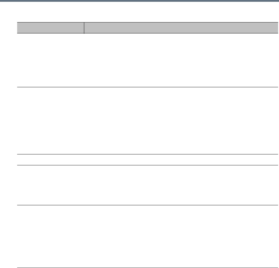
IP Network Services
Polycom, Inc. 492
10 To view or modify the ports values, click the Ports tab.
Register as Gateway Select this check box if the Collaboration Server is to be seen as a gateway, for
example, when using a Cisco gatekeeper.
Notes:
•Do not select this check box when using Polycom ReadiManager or a
Radvision gatekeeper.
•Gateway functionality is not supported by Collaboration Server (RMX)
1800-0.
Refresh Registration
every __ seconds
The frequency with which the system informs the gatekeeper that it is active by
re-sending the IP address and aliases of the IP cards to the gatekeeper. If the IP
card does not register within the defined time interval, the gatekeeper will not
refer calls to this IP card until it re-registers. If set to 0, re-registration is
disabled.
Note:
•It is recommended to use default settings.
•This is a re-registration and not a ‘keep alive’ operation – an alternate
gatekeeper address may be returned.
Aliases
Alias The alias that identifies the Collaboration Server’s Signaling Host within the
network. Up to five aliases can be defined for each Collaboration Server.
Note: When a gatekeeper is specified, at least one alias must be entered in the
table.
Additional aliases or prefixes may also be entered.
Type The type defines the format in which the card’s alias is sent to the gatekeeper.
Each alias can be of a different type:
•H.323 ID (alphanumeric ID)
•E.164 (digits 0-9)
•Email ID (email address format, e.g. abc@example.com)
•Participant Number (digits 0-9, * and #)
Note: Although all types are supported, the type of alias to be used depends on
the gatekeeper’s capabilities.
Default IP Service – Conferencing – Gatekeeper Parameters
Field Description
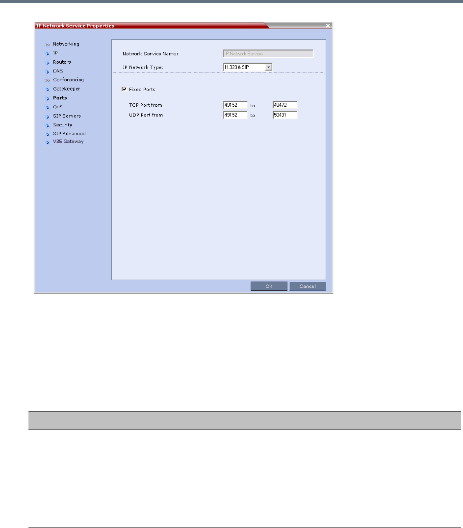
IP Network Services
Polycom, Inc. 493
Settings in the Ports tab allow specific ports in the firewall to be allocated to multimedia conference
calls.
The port range recommended by IANA (Internet Assigned Numbers Authority) is 49152 to 65535.
The Collaboration Server uses this recommendation along with the number of licensed ports to
calculate the port range.
11 Modify the following fields:
Default IP Service – Conferencing – Ports Parameters
Field Description
Fixed Ports Leave this check box cleared if you are defining a Network Service for local calls
that do not require configuring the firewall to accept calls from external entities.
When cleared, the system uses the default port range and allocates 4 RTP and
4 RTCP ports for media channels (Audio, Video, Content and FECC).
Note: When ICE Environment is enabled, 8 additional ports are allocated to
each call.
Click this check box to manually define the port ranges or to limit the number of
ports to be left open.
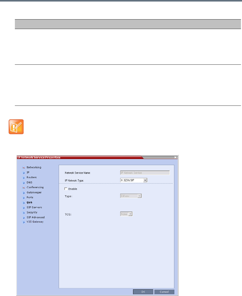
IP Network Services
Polycom, Inc. 494
12 If required, click the QoS tab.
TCP Port from - to Displays the default settings for port numbers used for signaling and control.
To modify the number of TCP ports, enter the first and last port numbers in the
range.
The number of ports is calculated as follows:
Number of simultaneous calls x 2 ports (1 signaling + 1 control).
UDP Port from - to Displays the default settings for port numbers used for audio and video.
To modify the number of UDP ports:
•Enter the first and last port numbers in the range, and the range must be 3000
ports per media card.
•When ICE environment is enabled, the range must be 6000 ports per media
card.
If you do not specify an adequate port range, the system will accept the settings but will issue a
warning. Calls will be rejected when the Collaboration Server’s ports are exceeded.
Default IP Service – Conferencing – Ports Parameters
Field Description

IP Network Services
Polycom, Inc. 495
Quality of Service (QoS) is important when transmitting high bandwidth audio and video information.
QoS can be measured and guaranteed in terms of:
• Average delay between packets
• Variation in delay (jitter)
• Transmission error rate
DiffServ and Precedence are the two QoS methods supported by the Collaboration Server. These
methods differ in the way the packet’s priority is encoded in the packet header.
The Collaboration Server’s implementation of QoS is defined per Network Service, not per endpoint.
13 View or modify the following fields:
The routers must support QoS in order for IP packets to get higher priority.
Default IP Service – Conferencing – QoS Parameters
Field Description
Enable Select to enable the configuration and use of the QoS settings.
When un-checked, the values of the DSCP (Differentiated Services Code Point)
bits in the IP packet headers are zero.
Type DiffServ and Precedence are two methods for encoding packet priority. The
priority set here for audio video and IP Signaling packets should match the
priority set in the router.
•DiffServ: Select when the network router uses DiffServ for priority encoding.
The default priorities for both audio and video packets is 0x31. These values
are determined by the QOS_IP_VIDEO and QOS_IP_AUDIO flags in the
system.cfg file.
The default priority for Signaling IP traffic is 0x00 and is determined by the
QOS_IP_SIGNALING flag in the system.cfg file.
For more information Modifying System Flags.
• Precedence: Select when the network router uses Precedence for priority
encoding, or when you are not sure which method is used by the router.
Precedence should be combined with None in the TOS field.
The default priority is 5 for audio and 4 for video packets.
Note: Precedence is the default mode as it is capable of providing priority
services to all types of routers, as well as being currently the most common
mechanism.
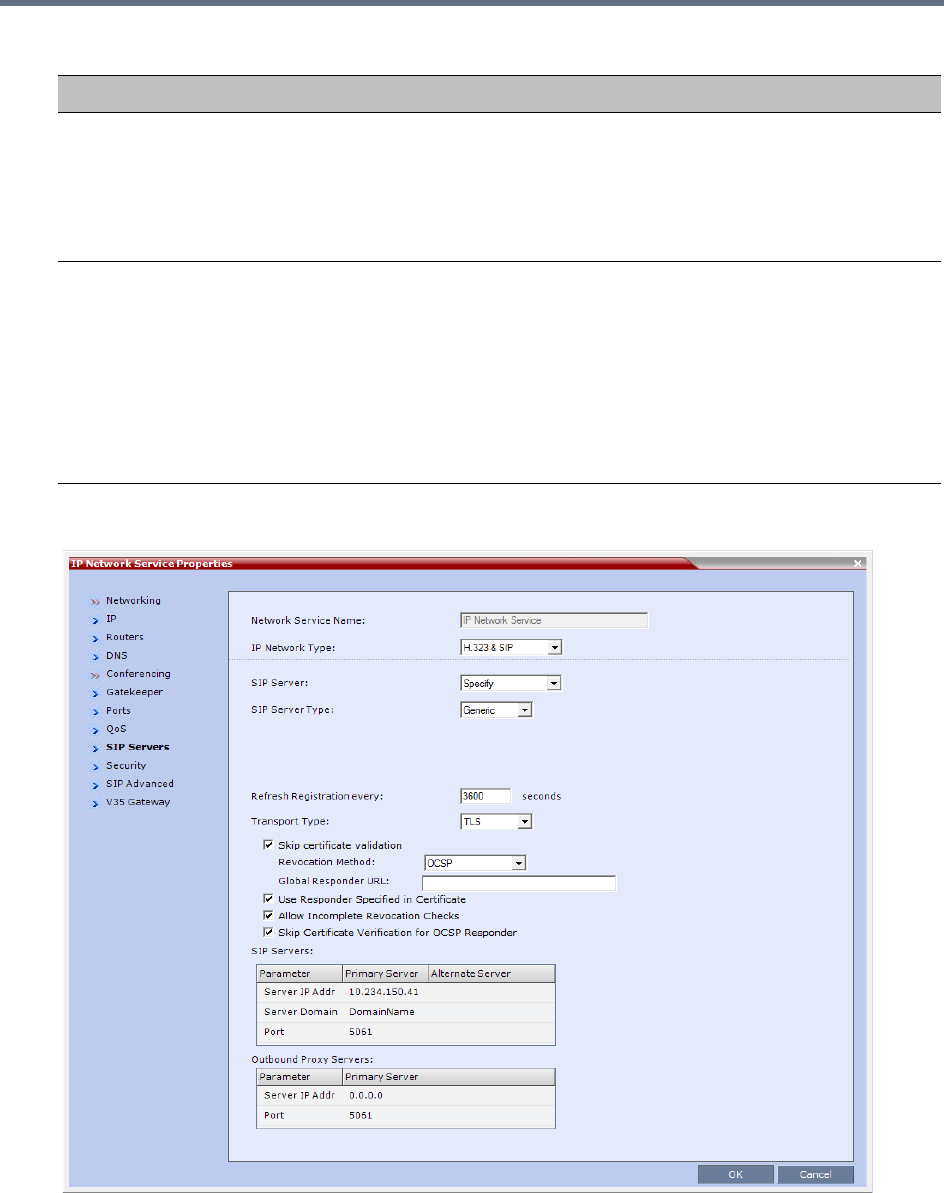
IP Network Services
Polycom, Inc. 496
14 Click the SIP Servers tab.
15 Modify the following fields:
Audio / Video You can prioritize audio and video IP packets to ensure that all participants in
the conference hear and see each other clearly. Select the desired priority. The
scale is from 0 to 5, where 0 is the lowest priority and 5 is the highest. The
recommended priority is 4 for audio and 4 for video to ensure that the delay for
both packet types is the same and that audio and video packets are
synchronized and to ensure lip sync.
TOS Select the type of Service (TOS) that defines optimization tagging for routing the
conferences audio and video packets.
• Delay: The recommended default for video conferencing; prioritized audio
and video packets tagged with this definition are delivered with minimal delay
(the throughput of IP packets minimizes the queue sequence and the delay
between packets).
•None: No optimization definition is applied. This is a compatibility mode in
which routing is based on Precedence priority settings only. Select None if
you do not know which standard your router supports.
Default IP Service – Conferencing – QoS Parameters
Field Description

IP Network Services
Polycom, Inc. 497
Default IP Network Service – SIP Servers
Field Description
SIP Server Select:
• Specify – To manually configure SIP servers.
•Off – If SIP servers are not present in the network.
Note: When set to Specify, the Security tab is displayed.
SIP Server Type Select:
•Generic - For non Microsoft environments.
•Microsoft - For Microsoft SIP environments.
Refresh Registration This defines the time in seconds, in which the Collaboration Server refreshes it’s
registration on the SIP server. For example, if “3600” is entered the
Collaboration Server will refresh it’s registration on the SIP server every 3600
seconds.
Transport Type Select the protocol that is used for signaling between the Collaboration Server
and the SIP Server or the endpoints according to the protocol supported by the
SIP Server:
UDP – Select this option to use UDP for signaling.
TCP – Select this option to use TCP for signaling.
TLS – The Signaling Host listens on secured port 5061 only and all outgoing
connections are established on secured connections. Calls from SIP clients or
servers to non secured ports are rejected.
The following protocols are supported: TLS 1.0, SSL 2.0 and SSL 3.0.
Note: If TLS is selected, the Skip Certificate Validation and the other
certificate related fields are displayed.
Skip Certificate Validation When checked, no Certificate Validation is performed.
Revocation Method
For a detailed description, see Certificate Management and Certificate
Revocation.
Global Responder URL
Use Responder Specified
in Certificate
Allow Incomplete
Revocation Checks
Skip Certificate Validation
for OSCP Responder
SIP Servers: Primary / Alternate Server Parameter
Server IP Address Enter the IP address of the preferred SIP server.
If a DNS is used, you can enter the SIP server name.
Note: When in IPv4&IPv6 or in IPv6 mode, it is easier to use Names instead of
IP Addresses.
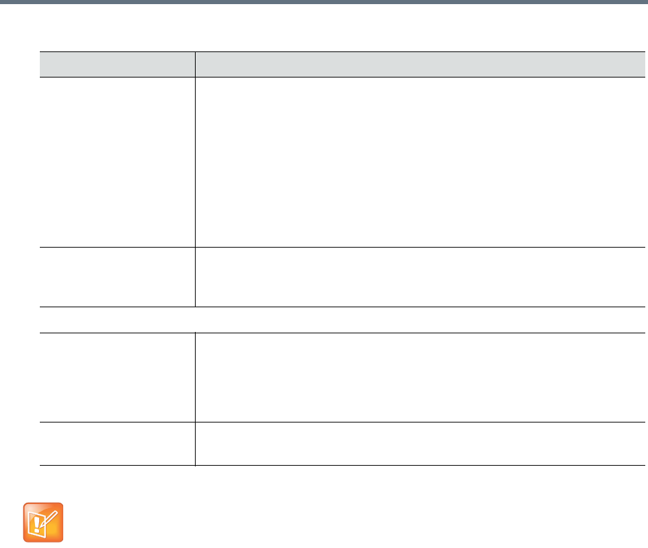
IP Network Services
Polycom, Inc. 498
16 Click the Security tab.
(This tab is only displayed if the SIP Server field in the SIP Servers tab is set to Specify.)
Server Domain Name Enter the name of the domain that you are using for conferences, for example:
user_name@domain name
The domain name is used for identifying the SIP server in the appropriate
domain according to the host part in the dialed string.
For example, when a call to EQ1@polycom.com reaches its outbound proxy,
this proxy looks for the SIP server in the polycom.com domain, to which it will
forward the call.
When this call arrives at the SIP server in polycom.com, the server looks for
the registered user (EQ1) and forwards the call to this Entry Queue or
conference.
Port Enter the number of the TCP or UDP port used for listening. The port number
must match the port number configured in the SIP server.
Default port is 5060.
Outbound Proxy Servers: Primary / Alternate Server Parameter
Server IP Address By default, the Outbound Proxy Server is the same as the SIP Server. If they
differ, modify the IP address of the Outbound Proxy and the listening port
number (if required).
Note: When in IPv4&IPv6 or in IPv6 mode, it is easier to use Names instead of
IP Addresses.
Port Enter the port number the outbound proxy is listening to.
The default port is 5060.
When updating the parameters of the SIP Server in the IP Network Service - SIP Servers dialog
box, the Collaboration Server must be reset to implement the change.
Default IP Network Service – SIP Servers
Field Description
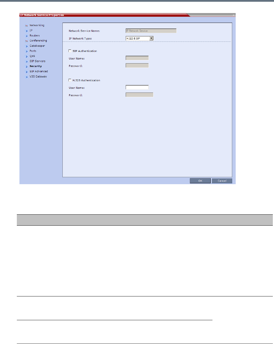
IP Network Services
Polycom, Inc. 499
17 Modify the following fields:
Default IP Network Service – Security (SIP Digest)
Field Description
SIP Authentication Click this check box to enable SIP proxy
authentication.
Select this check box only if the authentication is
enabled on the SIP proxy, to enable the Collaboration
Server to register with the SIP proxy. If the
authentication is enabled on the SIP proxy and
disabled on the RMX, calls will fail to connect to the
conferences.
Leave this check box cleared if the authentication
option is disabled on the SIP proxy.
User Name Enter the user name the Collaboration Server will use
to authenticate itself with the SIP proxy. This name
must be defined in the SIP Proxy.
These fields can
contain up to 20 ASCII
characters.
Password Enter the password the Collaboration Server will use
to authenticate itself with the SIP proxy. This
password must be defined in the SIP proxy.
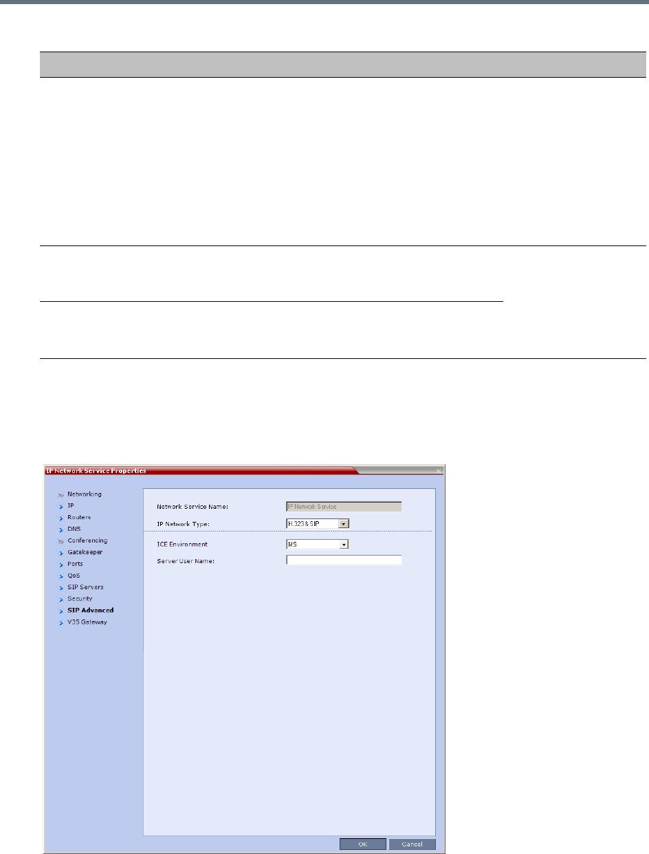
IP Network Services
Polycom, Inc. 500
If the Authentication User Name and Authentication Password fields are left empty, the SIP
Digest authentication request is rejected. For registration without authentication, the Collaboration
Server must be registered as a trusted entity on the SIP server.
18 To configure the ICE environment, click the SIP Advanced tab.
H.323 Authentication Click this check box to enable H.323 server
authentication.
Select this check box only if the authentication is
enabled on the gatekeeper, to enable the
Collaboration Server to register with the gatekeeper. If
the authentication is enabled on the gatekeeper and
disabled on the RMX, calls will fail to connect to the
conferences.
Leave this check box cleared if the authentication
option is disabled on the gatekeeper.
User Name Enter the user name the Collaboration Server will use
to authenticate itself with the gatekeeper. This name
must be defined in the gatekeeper.
These fields can
contain up to 64 ASCII
characters.
Password Enter the password the Collaboration Server will use
to authenticate itself with the gatekeeper. This
password must be defined in the gatekeeper.
Default IP Network Service – Security (SIP Digest)
Field Description
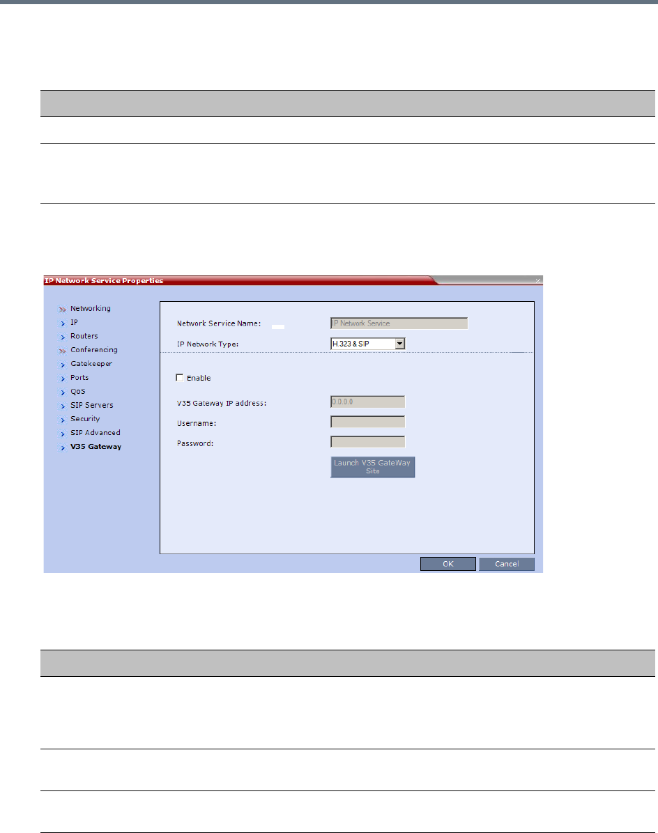
IP Network Services
Polycom, Inc. 501
19 Modify the following fields:
20 To view or modify the V35 gateway parameters, click the V35 Gateway tab.
The V35 Gateway dialog box is displayed.
21 Modify the following fields:
22 Click the OK button.
Default IP Network Service – SIP Advanced
Field Description
ICE Environment Select MS (for Microsoft ICE implementation) to enable the ICE integration.
Server User Name Enter the Collaboration Server User name as defined in the Active Directory.
For example, enter rmx1234.
This field is disabled if the ICE Environment field is set to None.
Network Service - V35 tab
Field Description
V35 Gateway IP
Address
Enter the Management IP address of the management interface of the Serial
Gateway. For more information see the RealPresence Collaboration Server
(RMX) 1500/2000/4000 Deployment Guide for Maximum Security Environments,
Serial Gateway S4GW - Maximum Security Mode.
Username Enter the User Name that the Collaboration Server uses to log in to the
management interface of the Serial Gateway.
Password Enter the Password that the Collaboration Server uses to log in to management
interface of the Serial Gateway.
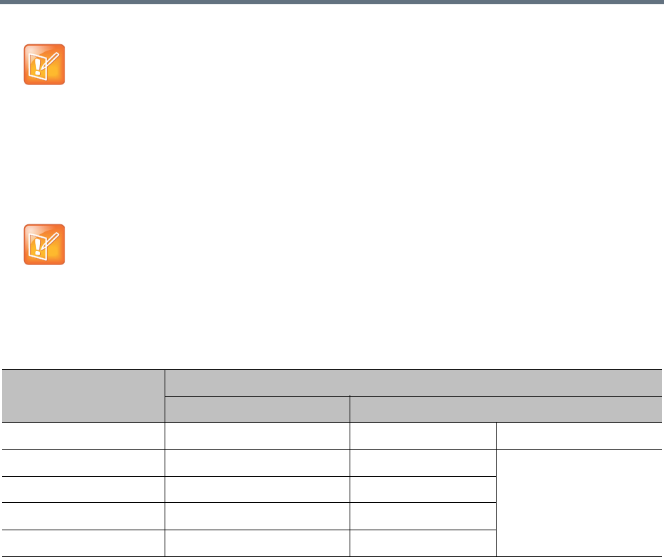
IP Network Services
Polycom, Inc. 502
Ethernet Settings
The automatically identified speed and transmit/receive mode of each LAN port used by the system can be
manually modified if a specific switch requires it. These settings can be modified in the Ethernet Settings
dialog box.
The following table lists the physical mapping of Port Type to the physical label on the back panel of the
RealPresence Collaboration Server (RMX) 1500.
When updating the parameters of the SIP Server in the IP Network Service - SIP Servers dialog
box, the Collaboration Server must be reset to implement the change.
RealPresence Collaboration Server (RMX) 1500: The Port numbers displayed in the dialog box
do not reflect the physical Port numbers as labeled on the RealPresence Collaboration Server
(RMX) 1500.
Physical Mapping - Port Type to Label on RealPresence Collaboration Server 1500/4000
Port Type
Label on MCU
1500 4000
Media LAN 2 LAN 2 RTM LAN Card
Modem Modem LAN 1 RTM-IP 4000 Card
Management 1 MNG B LAN 2
Signaling 1 MNG LAN 3
ShM Shelf LAN 6
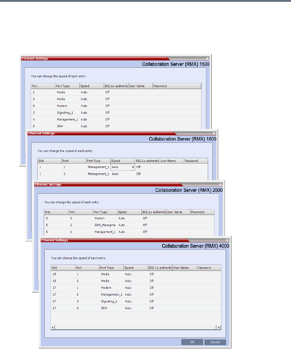
IP Network Services
Polycom, Inc. 503
To modify the automatic LAN port configuration:
1On the Collaboration Server menu, select Setup > Ethernet Settings.
The Ethernet Settings dialog box specific to the system you are using is displayed; some examples
are shown below.
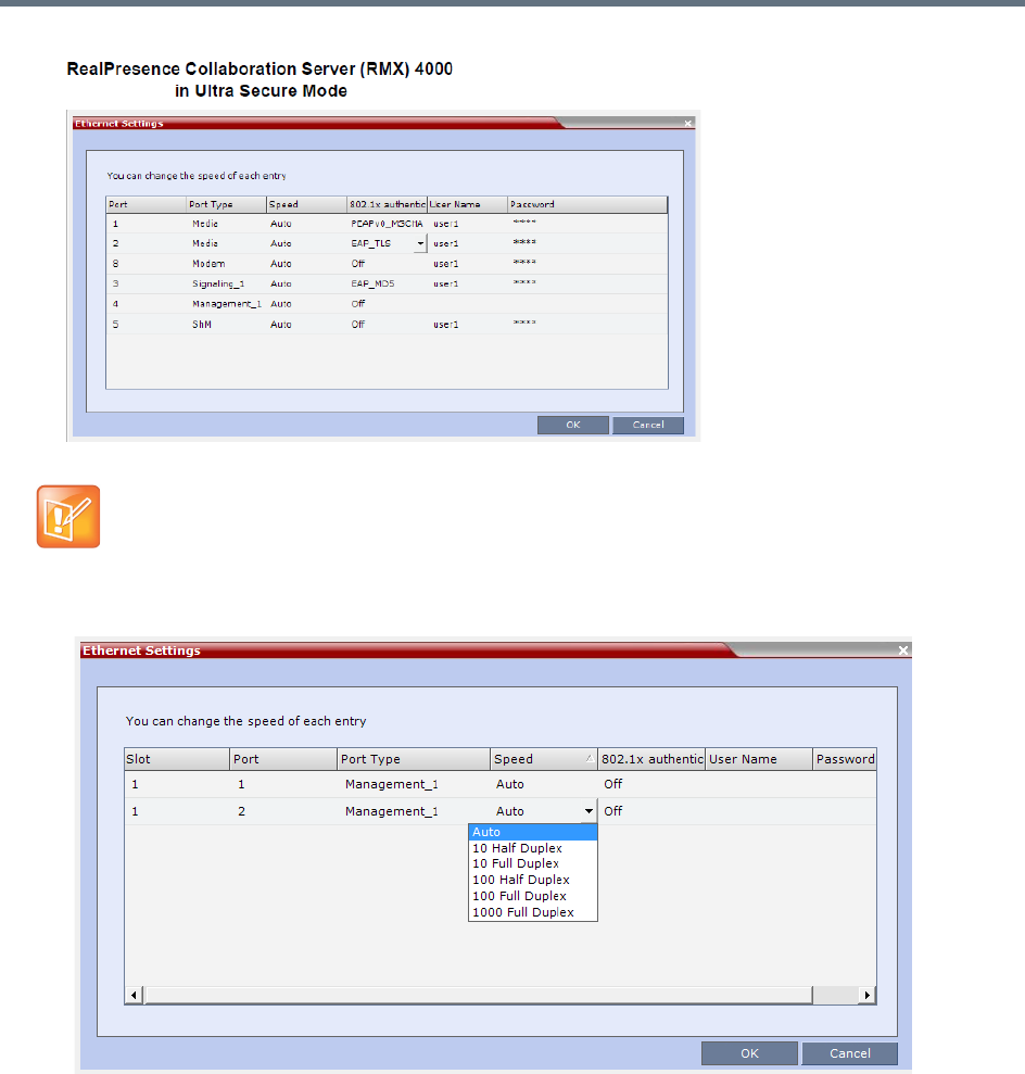
IP Network Services
Polycom, Inc. 504
2Select the speed and transmit/receive mode for each ports as follows:
RealPresence Collaboration Server (RMX) 1500/4000 :
Although the RTM LAN (media card) ports are shown as Port 1 in the Ethernet Settings and
Hardware Monitor, the physical LAN connection is Port 2.
IP Network Services
Polycom, Inc. 505
3Click OK.
Ethernet Settings Parameters
Field Description
Speed The Collaboration Server 1500/1800 has 2 LAN ports that can be configured.
The Collaboration Server 2000/4000 has 3 LAN ports on the RTM-IP (Management,
Signaling and Shelf Management), and additional LAN ports on each media card (RTM
LAN) and RTM ISDN cards. You can set the speed and transmit/receive mode
manually for these ports.
Port The LAN port number.
Note: Do not change the automatic setting of Port 1,4 and Port 5 of
the Management 2 and Signaling 2 Networks. Any change to the
speed of these ports will not be applied.
Speed Select the speed and transmit/receive mode for each port.
Default: Auto – Negotiation of speed and transmit/receive mode starts
at 1000 Mbits/second Full Duplex, proceeding downward to
10 Mbits/second Half Duplex.
Notes:
To maximize conferencing performance, especially in high bit rate call
environments, a 1Gb connection is recommended.
• RealPresence Collaboration Server (RMX) 4000 - Do not select
1000 Full Duplex for any LAN ports in Slot 17.
Select only 100 Full Duplex.
• RealPresence Collaboration Server (RMX) 1500 - Do not select
1000 Full Duplex for Port 5 (ShM).
Select only 100 Full Duplex.
802.1x
Authentication
For more information about 8.2.1x Authentication see IEEE 802.1X Authentication.
User Name
Password
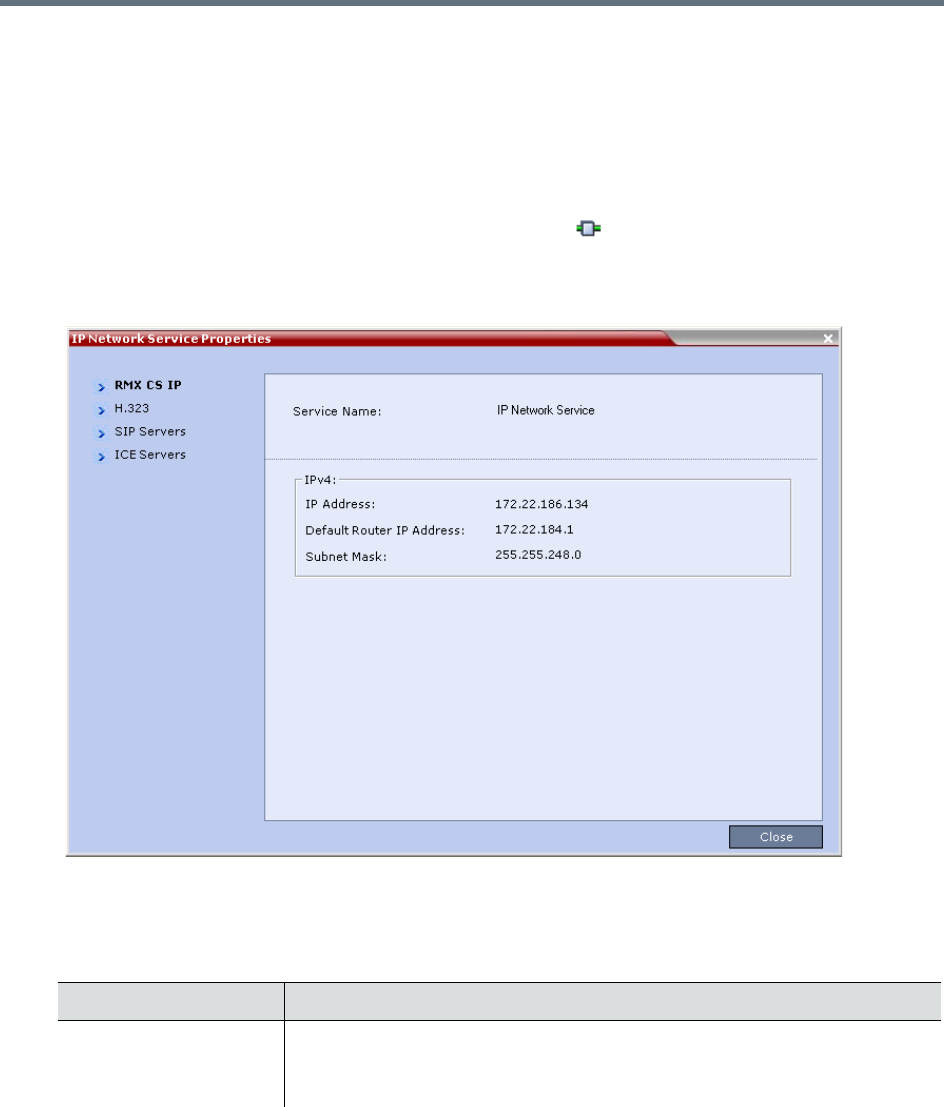
IP Network Services
Polycom, Inc. 506
IP Network Monitoring
The Signaling Monitor is the Collaboration Server entity used for monitoring the status of external network
entities such as the gatekeeper, DNS, SIP proxy and Outbound proxy and their interaction with the MCU.
To monitor signaling status:
1In the RMX Management pane, click Signaling Monitor ().
2In the Signaling Monitor pane, double-click Default IP Service.
The IP Network Services Properties – RMX CS IP tab opens:
The RMX CS IP tab displays the following fields:
IP Network Services Properties – RMX CS IP Parameters
Field Description
Service Name The name assigned to the IP Network Service by the Fast Configuration
Wizard.
Note: This field is displayed in all tabs.
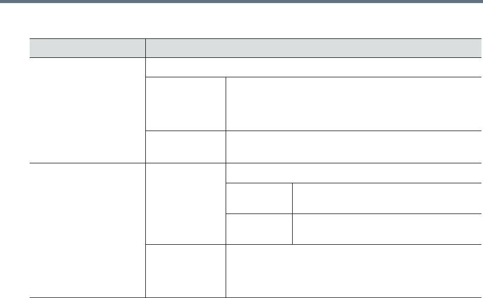
IP Network Services
Polycom, Inc. 507
IPv4 IP Address
Default Router
IP Address
The IP address of the default router. The default router is
used whenever the defined static routers are not able to
route packets to their destination. The default router is also
used when host access is restricted to one default router.
Subnet Mask The subnet mask of the MCU.
Default value: 255.255.255.0.
IPv6 Scope IP Address
Global The Global Unicast IP address of the
Collaboration Server.
Site-Local The IP address of the Collaboration Server
within the local site or organization.
Default Router
IP Address
The IP address of the default router. The default router is
used whenever the defined static routers are not able to
route packets to their destination. The default router is also
used when host access is restricted to one default router.
IP Network Services Properties – RMX CS IP Parameters
Field Description
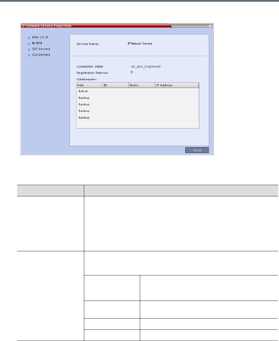
IP Network Services
Polycom, Inc. 508
3Click the H.323 tab.
The H.323 tab displays the following fields:
IP Network Services Properties – H.323 Parameters
Field Description
Connection State The state of the connection between the Signaling Host and the gatekeeper:
Discovery - The Signaling Host is attempting to locate the gatekeeper.
Registration - The Signaling Host is in the process of registering with the
gatekeeper.
Registered - The Signaling Host is registered with the gatekeeper.
Not Registered - The registration of the Signaling Host with the gatekeeper
failed.
Registration Interval The interval in seconds between the Signaling Host’s registration messages to
the gatekeeper. This value is taken from either the IP Network Service or from
the gatekeeper during registration. The lesser value of the two is chosen.
Role Active - The active gatekeeper.
Backup - The backup gatekeeper that can be used if
the connection to the preferred gatekeeper fails.
ID The gatekeeper ID retrieved from the gatekeeper during
the registration process.
Name The gatekeeper’s host’s name.
IP Address The gatekeeper’s IP address.
IP Network Services
Polycom, Inc. 509
4Click the SIP Servers tab.
The SIP Servers tab displays the following fields:
IP Network Services Properties – SIP Servers Parameters
Field Description
Role Active -The default SIP Server is used for SIP traffic.
Backup -The SIP Server is used for SIP traffic if the preferred proxy fails.
Name The name of the SIP Server.
IP Address The SIP Server's IP address.
Status The connection state between the SIP Server and the Signaling Host.
Not Available - No SIP server is available.
Auto - Gets information from DHCP, if used.
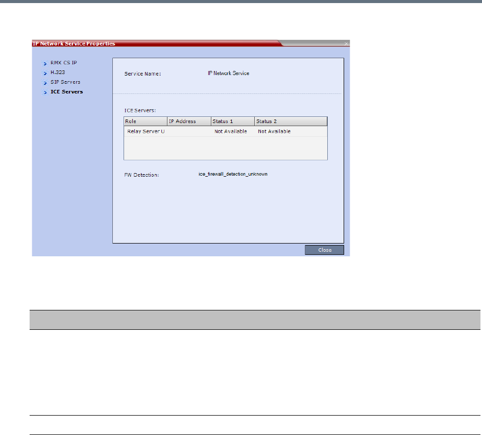
IP Network Services
Polycom, Inc. 510
5Click the ICE Servers tab.
The ICE Servers tab displays the following fields:
IP Network Services Properties – ICE Servers Parameters
Field Description
Role The ICE Server’s role is displayed:
•STUN password server
•STUN Server UDP
•STUN Server TCP
•Relay Server UDP
•Relay Server TCP
IP Address The ICE Server’s IP Address.

IP Network Services
Polycom, Inc. 511
Status 1/2/3/4 A status is displayed for each media card installed in the Collaboration Server:
•Connection O.K.
•MS – register fail
•MS – subscribe fail
•MS – service fail
•Connection failed
•User/password failed
•Channel didn't receive any packets for 5 seconds
•Channel exceeded allotted bandwidth
•Unknown failure
In systems with multiple media cards, Status 1 refers to the uppermost media
card.
FW Detection The Firewall Detection status is displayed:
•Unknown
•UDP enabled
•TCP enabled
•Proxy -TCP is possible only through proxy
•Block – both UDP & TCP blocked
•None
IP Network Services Properties – ICE Servers Parameters
Field Description
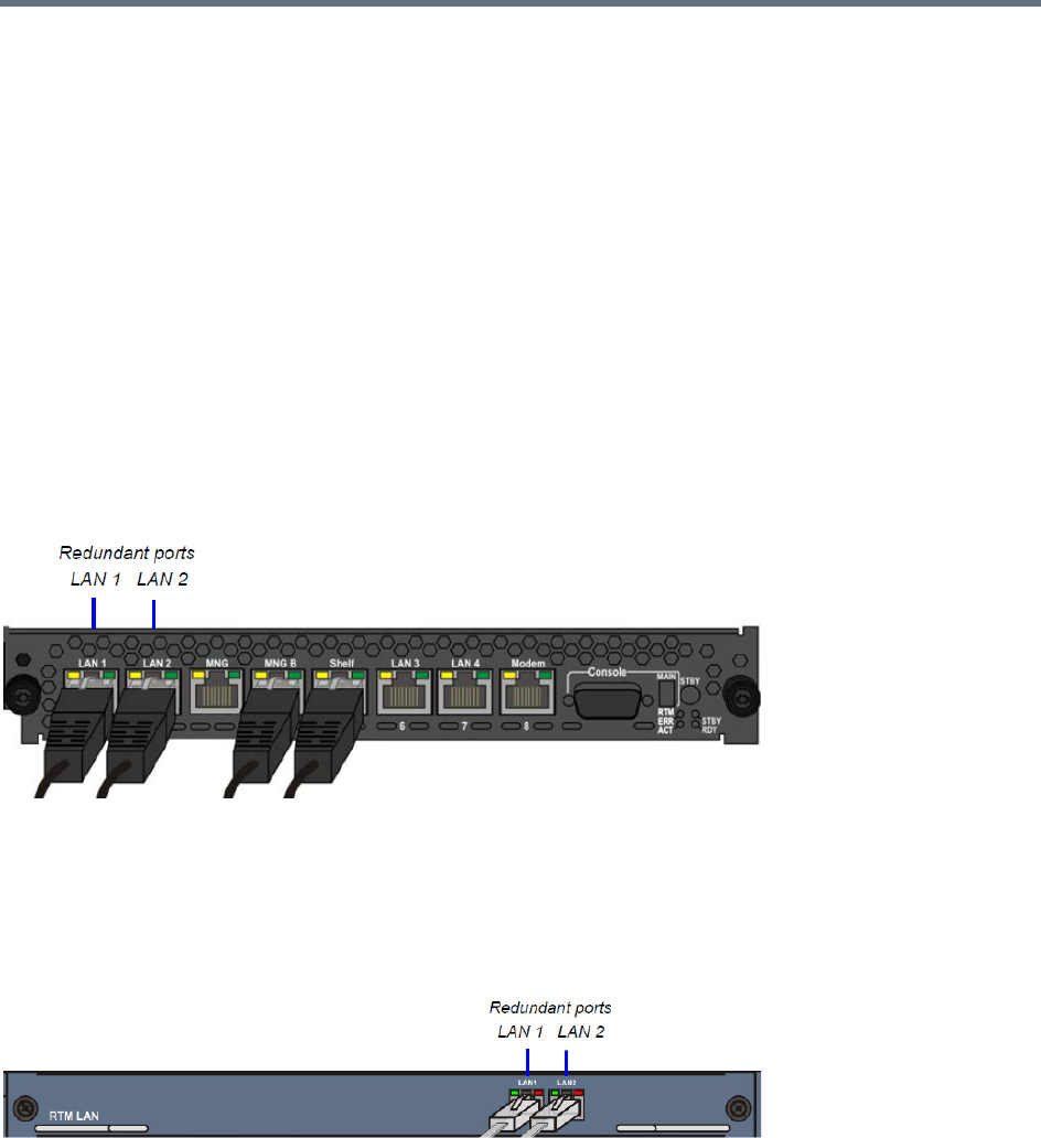
IP Network Services
Polycom, Inc. 512
LAN Redundancy
LAN Redundancy enables the redundant LAN port connection to automatically replace the failed LAN port
by using another physical connection and NIC (Network Interface Card). When a LAN port fails, IP network
traffic failure is averted and network or endpoints disconnections do not occur. When LAN cables are
connected to both LAN 1 and LAN 2 ports, the RMX automatically selects which port is active and which is
redundant.
Media Redundancy
Media Redundancy on RealPresence Collaboration Server (RMX) 1500
On the RealPresence Collaboration Server (RMX) 1500 LAN 1 and LAN 2 are the redundant media ports:
●LAN 2 port is used for standard communications
●LAN 1 port can be used to define a second Network Service or for LAN Redundancy
RealPresence Collaboration Server (RMX) 1500 - RTM IP 1500 on Rear Panel
Media Redundancy on RealPresence Collaboration Server (RMX) 2000/4000
On the RealPresence Collaboration Server (RMX) 2000 and RealPresence Collaboration Server (RMX)
4000, the LAN 1 and LAN 2 port on the RTM LAN card can be used as redundant media ports.
RealPresence Collaboration Server (RMX) 2000/4000 RTM LAN Card on Rear Panel
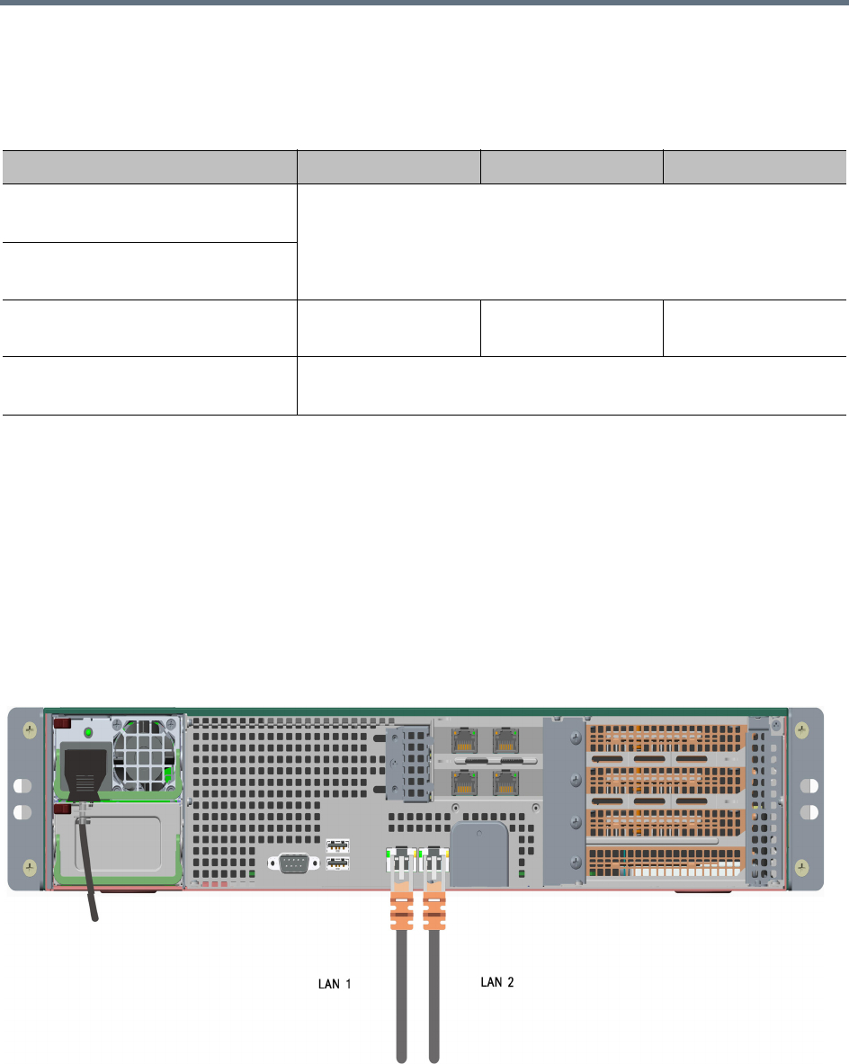
IP Network Services
Polycom, Inc. 513
Media Redundancy on the RealPresence Collaboration Server (RMX) 1500/2000/4000 is dependent on the
settings of the LAN_REDUNDANCY and MULTIPLE_SERVICES System Flags as summarized in the
following table:
Media Redundancy is not supported on any of the RMX RTM ISDN cards.
Media and Signaling Redundancy on RealPresence Collaboration Server (RMX)
1800
On the RealPresence Collaboration Server 1800 LAN 1 and LAN 2 are the redundant media and signaling
ports:
●LAN 1 port is used for standard communications
●LAN 2 port can be used to define a second Network Service or for LAN Redundancy
The following cables are connected to the LAN ports on the rear panel of the RealPresence Collaboration
Server 1800:
RMX 1500 / 2000 / 4000 - Media Redundancy - System Flags
System Flag / Value RMX 1500 RMX 2000 RMX 4000
LAN_REDUNDANCY = NO
MULTIPLE_SERVICES = NO
No Redundancy
LAN_REDUNDANCY = NO
MULTIPLE_SERVICES = YES
LAN_REDUNDANCY = YES
MULTIPLE_SERVICES = NO
Full Redundancy Media Redundancy
Only
Full Redundancy
LAN_REDUNDANCY = YES
MULTIPLE_SERVICES = YES
Full Media Redundancy
(If only one IP Network Service is defined per media card.)

IP Network Services
Polycom, Inc. 514
Media Redundancy on the RealPresence Collaboration Server (RMX) 1800 is dependent on the settings of
the LAN_REDUNDANCY and MULTIPLE_SERVICES System Flags as summarized in the following table:
Signaling and Management Redundancy
Signaling and Management Redundancy on RealPresence Collaboration Server
(RMX) 1500
On the RealPresence Collaboration Server (RMX) 1500, for Signaling and Management Redundancy, the
MNG port is redundant to the MNG B port and must have a LAN cable connected.
LAN Connections to the IP ports
IP Port Description
LAN 1 For management network connections:
When LAN redundancy is enabled, LAN 1 is used for management, media, and
signaling network connections.
LAN 2 For media, and signaling network connections:
When LAN redundancy is enabled, LAN 2 is the backup for the LAN 1 port.
RMX 1800 - Media Redundancy - System Flags
System Flag / Value RMX 1800
LAN_REDUNDANCY = NO
MULTIPLE_SERVICES = NO
No Redundancy.
If a second LAN cable is connected to Port 2, Network separation is
enabled (the Management Network Service is separated from the Default
IP Network Service)
LAN_REDUNDANCY = NO
MULTIPLE_SERVICES = YES
No Redundancy.
LAN_REDUNDANCY = YES
MULTIPLE_SERVICES = NO
Full Redundancy
LAN_REDUNDANCY = YES
MULTIPLE_SERVICES = YES
These flags cannot be set to YES simultaneously.
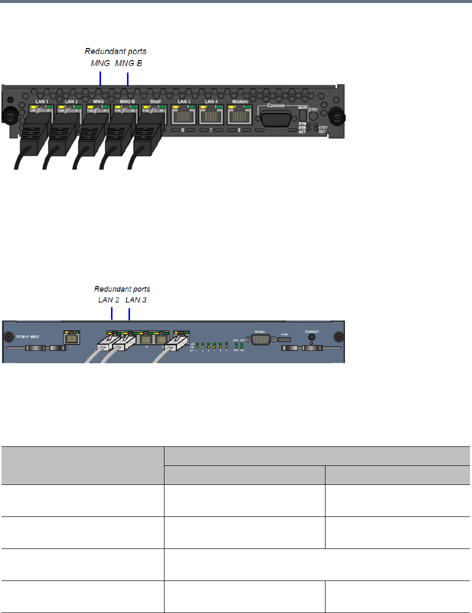
IP Network Services
Polycom, Inc. 515
RealPresence Collaboration Server (RMX) 1500 - RTM IP 1500 on Rear Panel
Signaling and Management Redundancy on RealPresence Collaboration Server
(RMX) 4000
On the RealPresence Collaboration Server (RMX) 4000, for Signaling and Management Redundancy when
LAN_REDUNDANCY = YES and MULTIPLE_SERVICES = NO, the LAN 3 port on the RTM-IP 4000 card
is redundant to the LAN 2 port. LAN ports 4 and 5 are never used.
RealPresence Collaboration Server (RMX) 4000 - RTM IP 4000 on Rear Panel2
On the RealPresence Collaboration Server (RMX) 1500/4000 Signaling and Management Redundancy is
implemented using the LAN ports on the RTM-IP card and is dependent on the settings of the
LAN_REDUNDANCY and MULTIPLE_SERVICES System Flags as summarized in the following table.
RMX 1500 / 4000 - Signaling and Management Redundancy - System Flags
Flag / Value
Port Usage
LAN 2 / MNG B (RMX 1500)LAN 3 / MNG (RMX 1500)
LAN_REDUNDANCY = NO
MULTIPLE_SERVICES = NO
Management Signaling
LAN_REDUNDANCY = NO
MULTIPLE_SERVICES = YES
Management Not Used
LAN_REDUNDANCY = YES
MULTIPLE_SERVICES = NO
Management & Signaling
(LAN3 is redundant to LAN 2)
LAN_REDUNDANCY = YES
MULTIPLE_SERVICES = YES
Management Management
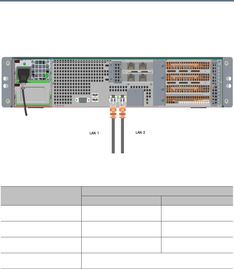
IP Network Services
Polycom, Inc. 516
Management Redundancy on RealPresence Collaboration Server (RMX) 1800
On the RealPresence Collaboration Server 1800, for Management Redundancy, the LAN 2 port is
redundant to the LAN 1 port and must have a LAN cable connected.
LAN Redundancy is not supported by Collaboration Server (RMX) 1800-0.
RealPresence Collaboration Server 1800 - LAN 2 connection on Rear Panel
On the RealPresence Collaboration Server 1800, Management Redundancy is implemented using the LAN
1 and LAN 2 ports and is dependent on the settings of the LAN_REDUNDANCY and
MULTIPLE_SERVICES System Flags as summarized in the following table.
RMX 1800 - Management Redundancy - System Flags
Flag / Value
Port Usage
LAN 1 LAN 2
LAN_REDUNDANCY = NO
MULTIPLE_SERVICES = NO
Management Media and Signaling
LAN_REDUNDANCY = NO
MULTIPLE_SERVICES = YES
Management Media and Signaling
LAN_REDUNDANCY = YES
MULTIPLE_SERVICES = NO
Management, Media and Signaling. LAN 2 is redundant to LAN 1
LAN_REDUNDANCY = YES
MULTIPLE_SERVICES = YES
These flags cannot be set to YES simultaneously.

IP Network Services
Polycom, Inc. 517
Configuration Requirements
LAN Redundancy is disabled by default and is enabled by changing the LAN_REDUNDANCY system flag
to YES and connecting the appropriate LAN cables to the LAN ports on the Collaboration Server as follows:
RealPresence Collaboration Server (RMX) 1500
»Connect the additional LAN cable to LAN 1 port on the RTM IP.
RealPresence Collaboration Server 1800
»Connect the additional LAN cable to LAN 2 port on the rear panel of the Collaboration Server 1800.
RealPresence Collaboration Server (RMX) 2000
●Connect the additional LAN cable to LAN 1 port on the RTM LAN.
●In the Setup> System Configuration > System Flags dialog box, add the flag
RMX2000_RTM_LAN and set it to YES to activate the installed RTM LAN card.
●On the RealPresence Collaboration Server (RMX) 2000, LAN Redundancy can be enabled
simultaneously with Multiple Networks. To enable the Multiple Networks option, set the
MULTIPLE_SERVICES flag to YES.
●A system reset is required when adding the RMX2000_RTM_LAN flag.
RealPresence Collaboration Server (RMX) 4000
●Connect the additional LAN cable to LAN 1 port on the RTM LAN.
●On the RealPresence Collaboration Server (RMX) 4000, LAN Redundancy can be enabled
simultaneously with Multiple Networks. To enable the Multiple Networks option, set the
MULTIPLE_SERVICES flag to YES.
●If required, reset the Collaboration Server.
On all systems:
●LAN Redundancy can be disabled by setting the LAN_REDUNDANCY System Flag to NO.
●If the LAN_REDUNDANCY System Flag value set to NO, the LAN 2 port must be connected to the
IP network.
Hardware Monitor Indications
When LAN Redundancy is enabled on the Collaboration Server, LAN 2 port is Active. With LAN
redundancy, when LAN LEDs are lit they indicate that a physical connection of the cables is present but
On a RealPresence Collaboration Server (RMX) 2000, one RTM LAN card is required.
For more information see the RealPresence Collaboration Server (RMX) 2000 Hardware Guide,
Installing or Replacing the RTM LAN.
On the RMX 1500/2000/4000, full media redundancy is supported if only one IP Network Service is
defined per media card.
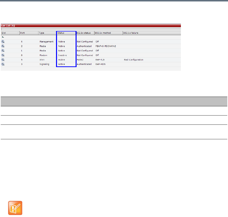
IP Network Services
Polycom, Inc. 518
does not indicate their activity status. In the Hardware Monitor pane the Lan List displays the Collaboration
Server LAN ports together with their Status indication.
The Hardware Monitor Status indications are summarized in the following table:
Network Traffic Control
The Network Traffic Control mechanism controls the level of UDP packets generated by the system. It
regulates a set of queuing systems and mechanisms by which UDP packets are received and transmitted
to the network router.
During a conference the MPMx cards occasionally blast-out UDP packets which can cause overloads on
the network. Collaboration Server bandwidth usage can increase to above the designated conference
participant line rate settings, causing network bandwidth issues such as latency and packet loss.
Three Network Traffic Control Flags are used to control the Network Traffic mechanism:
●ENABLE_TC_PACKAGE -
When the flag is set to NO (default), Network Traffic Control is disabled on the Collaboration Server.
Set the flag to YES to enable Network Traffic Control.
●TC_BURST_SIZE -
This flag regulates the Traffic Control buffer or max burst size as a percentage of the participant line
rate. In general, higher traffic rates require a larger buffer. For example, if the flag is set to 10 and the
participants line rate is 2MB, then the burst size is 200Kbps.
Default = 10
Flag range: 1-30.
RTM LAN Indications
Status Description
Active The LAN port cable is connected.
Inactive The LAN port cable is not connected.
Standby The LAN Redundancy option is enabled and this LAN port is the redundant and in
standby mode. In case of failure, this port becomes active.
Only supported in the MPMx Card Configuration mode.

IP Network Services
Polycom, Inc. 519
●TC_LATENCY_SIZE -
This flag limits the latency (in milliseconds) or the number of bytes that can be present in a queue.
Default = 500
Flag range: 1-1000 (in milliseconds).
SIP Proxy Failover With Polycom® Distributed Media
Application™ (DMA™) 7000
Collaboration Server systems that are part of a RealPresence DMA system environment can benefit from
the RealPresence DMA system’s SIP Proxy Failover functionality.
SIP Proxy Failover is supported in the RealPresence DMA system’s Local Clustering mode with redundancy
achieved by configuring two DMA servers to share a single virtual IP address.
The virtual IP address is used by the Collaboration Server as the IP address of its SIP Proxy.
No additional configuration is needed on the Collaboration Server.
Should a SIP Proxy failure occur in one of the RealPresence DMA system servers:
●The other RealPresence DMA system server takes over as SIP Proxy.
●Ongoing calls may be disconnected.
●Previously ongoing calls will have to be re-connected using the original IP address, registration and
connection parameters.
●New calls will connect using the original IP address, registration and connection parameters.
RealPresence Collaboration Server (RMX) Network
Port Usage
The following table summarizes the port numbers and their usage in the <Product Name>:
Server Network Port Usage Summary
Connection
Type
Port
Number Protocol Description Configurable
HTTP 80 TCP Management between the
Collaboration Server and
Collaboration Server Web Client.
No
HTTPS 443 TCP Secured Management between the
Collaboration Server and
Collaboration Server Web Client.
No
DNS 53 UDP Domain name server. Can be disabled in the IP
Network Service.
DHCP 68 UDP Dynamic Host Configuration
Protocol.
Can be disabled in the IP
Network Service.

IP Network Services
Polycom, Inc. 520
SSH 22 TCP Secured shell. It is the Collaboration
Server terminal.
SSH is not supported when the
Collaboration Server is in Ultra
Secure Mode. For more information
see Ultra Secure Mode.
No
NTP 123 UDP Network Time Protocol. Enables
access to a time server on the
network.
No
H.323 GK RAS 1719 UDP Gatekeeper RAS messages traffic. No
H.323 Q.931 1720 -
incoming;
49152-599
99 -
outgoing
TCP H.323 Q.931 call signaling.
Each outgoing call has a separate
port.
The port for each outgoing call is
allocated dynamically.
Yes - for outgoing calls
only.
It is configured in the
Fixed Ports section of the
IP service.
H.323 H.245 49152 -
59999
TCP H.245 control.
Each outgoing call has a separate
port.
The port for each outgoing call is
allocated dynamically. It can be
avoided by tunneling.
Yes - for outgoing calls
only.
It is configured in the
Fixed Ports section of the
IP service.
SIP server 5060
60000
UDP, TCP Connection to the SIP Server.
Sometimes port 60000 is used
when the system cannot reuse the
TCP port. This port can be set in the
Central signaling (CS) configuration
file.
Yes - in the IP service.
Alternative SIP
server
5060
60000
UDP, TCP Connection to the alternate SIP
Server.
Sometimes port 60000 is used
when the system cannot reuse the
TCP port. This port can be set in the
Central signaling (CS) configuration
file.
Yes - in the IP service.
SIP Outbound
proxy
5060
60000
UDP, TCP Connection to the SIP outbound
proxy.
Sometimes port 60000 is used
when the system cannot reuse the
TCP port. This port can be set in the
Central signaling (CS) configuration
file.
Yes - in the IP service.
Server Network Port Usage Summary
Connection
Type
Port
Number Protocol Description Configurable

IP Network Services
Polycom, Inc. 521
Alternative SIP
Outbound proxy
5060
60000
UDP, TCP Connection to the alternate SIP
outbound proxy.
Sometimes port 60000 is used
when the system cannot reuse the
TCP port. This port can be set in the
Central signaling (CS) configuration
file.
Yes - in the IP service.
SIP-TLS 60002 TCP Required for Binary Floor Control
Protocol (BFCP) functionality for
SIP People+Content content
sharing.
No - port is not opened if
SIP People+Content is
disabled.
RTP 49152 -
59999
UDP RTP media packets.
The ports are dynamically allocated.
Yes - It is configured in the
Fixed Ports section of the
IP service.
RTCP 49152 -
59999
UDP RTP control.
The ports are dynamically allocated.
Yes - It is configured in the
Fixed Ports section of the
IP service.
SIP -TLS 5061 TCP SIP -TLS for SIP server, alternate
SIP server, outbound proxy and
alternate outbound proxy.
No
Server Network Port Usage Summary
Connection
Type
Port
Number Protocol Description Configurable
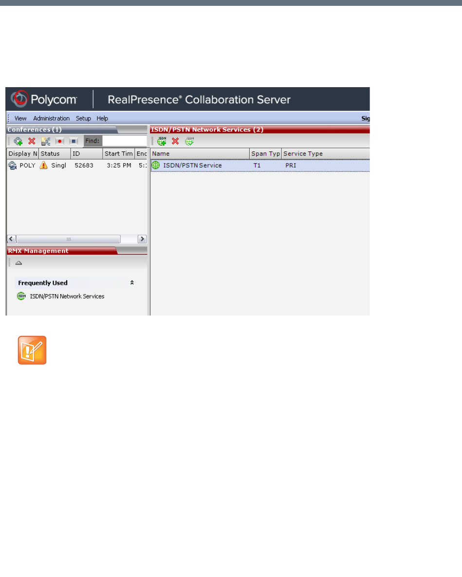
Polycom®, Inc. 522
Defining ISDN/PSTN Network Services
To enable the RealPresence Collaboration Server (RMX) to function within ISDN/PSTN network
environments, network parameters must be defined for the ISDN/PSTN Network Service.
The configuration dialog boxes for both these network services are accessed from the RMX Management
pane of the RMX Web Client or RMX Manager.
ISDN/PSTN Network Services Overview
To enable ISDN and PSTN participants to connect to the MCU, an ISDN/PSTN Network Service must be
defined. A maximum of two ISDN/PSTN Network Services, of the same Span Type (E1 or T1) can be
defined for the Collaboration Server. Each Network Service can attach spans from either or both cards.
Most of the parameters of the first ISDN/PSTN Network Service are configured in the Fast Configuration
Wizard, which runs automatically if an RTM ISDN card is detected in the Collaboration Server during first
time power-up. For more information, see Procedure 1: First-time Power-up in the Polycom RealPresence
Collaboration Server (RMX) 1500/1800/2000/4000 Getting Started Guide.
Note: DSP Cards
RealPresence Collaboration Servers (RMX) 1800 support ISDN/PSTN only with 3 DSP cards
installed, and with built-in ISDN hardware.
RealPresence Collaboration Server 1800-0 does not utilize DSP cards and does not support
ISDN/PSTN connections.

Defining ISDN/PSTN Network Services
Polycom®, Inc. 523
Supported Capabilities and Conferencing Features:
●ISDN video is supported only in Continuous Presence (CP) conferences.
●Only BONDING (using multiple channels as a single, large bandwidth channel) is supported.
●Simple audio negotiation.
●Supported video resolutions are the same as for IP.
●Supported video Protocols are the same as for IP: H.261, H.263, H.264.
●H.239 for content sharing.
●Lecture Mode.
●DTMF codes.
●Securing of conferences.
●Basic cascading between two MCUs using an ISDN link is available and forwarding of DTMF codes
can be suppressed.
Non Supported Capabilities and Conferencing Features:
●NFAS (Non-Facility Associated Signaling)
●Leased line usage
●Restricted Channel mode
●Aggregation of channels
●E1 and T1 spans cannot operate simultaneously
●V.35 serial standards
●Primary and secondary clock source configuration (they are automatically selected by the system)
●Auto detection of Audio Only setting at endpoint
●Auto re-negotiation of bit rate
●Additional network services (two currently supported)
●Change of video mode (capabilities) from remote side during call
●Audio algorithms G.729 and G.723.1
●FECC
●H.243 Chair Control
●T.120 data sharing protocol
●H.261 Annex D
●MIH Cascading using an ISDN connection as cascade link
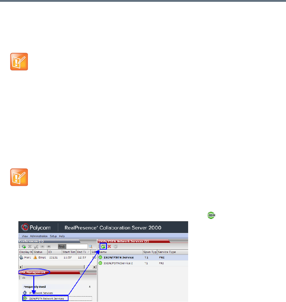
Defining ISDN/PSTN Network Services
Polycom®, Inc. 524
Adding/Modifying ISDN/PSTN Network Services
The system administrator can use the RMX Management – ISDN/PSTN Network Services section of the
Collaboration Server Web Client to add a second ISDN/PSTN Network Service or modify the first
ISDN/PSTN Network Service.
Obtaining ISDN/PSTN required information
Before configuring the ISDN/PSTN Network Service, obtain the following information from your ISDN/PSTN
Service Provider:
●Switch Type
●Line Coding and Framing
●Numbering Plan
●Numbering Type
●Dial-in number range
To Add an ISDN/PSTN Network Service:
1In the RMX Management pane, click ISDN/PSTN Network Services ().
A new ISDN/PSTN Network Service can be defined even if no RTM ISDN card is installed in the
system.
If the Collaboration Server is connected to the public ISDN Network, an external CSU or similar
equipment is needed.
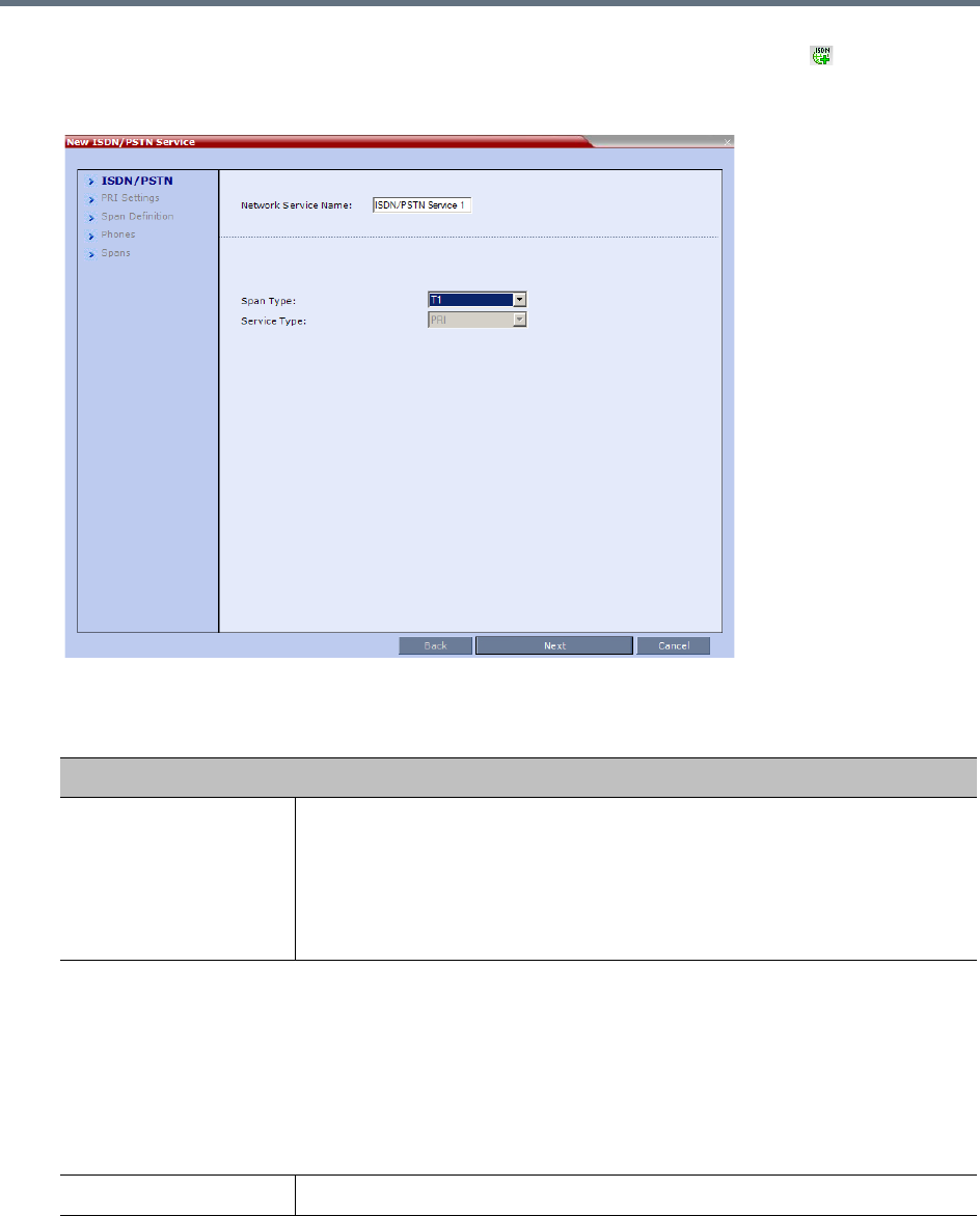
Defining ISDN/PSTN Network Services
Polycom®, Inc. 525
2In the ISDN/PSTN Network Services list menu, click New ISDN/PSTN Service ( ), or right-click
anywhere in the ISDN/PSTN Network Services list and select New ISDN/PSTN Service.
The Fast Configuration Wizard sequence begins with the ISDN/PSTN dialog box:
3Define the following parameters:
ISDN Service Settings
Field Description
Network Service Name Specify the service provider’s (carrier) name or any other name you choose,
using up to 20 characters. The Network Service Name identifies the ISDN/PSTN
Service to the system.
Default name: ISDN/PSTN Service
Note: This field is displayed in all ISDN/PSTN Network Properties tabs and can
contain character sets that use Unicode encoding.
Span Type Select the type of spans (ISDN/PSTN) lines, supplied by the service provider,
that are connected to the Collaboration Server. Each span can be defined as a
separate Network Service, or all the spans from the same carrier can be defined
as part of the same Network Service.
Select either:
•T1 (U.S. – 23 B channels + 1 D channel)
•E1 (Europe – 30 B channels + 1 D channel) Default: T1
Note: E1 and T1 spans cannot operate simultaneously.
Service Type PRI is the only supported service type. It is automatically selected.
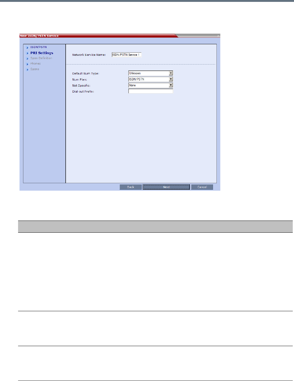
Defining ISDN/PSTN Network Services
Polycom®, Inc. 526
4Click Next.
The PRI Settings dialog box is displayed:
5Define the following parameters:
ISDN Service Settings
Field Description
Default Num Type Select the Default Num Type from the list.
The Num Type defines how the system handles the dialing digits. For example,
if you type eight dialing digits, the Num Type defines whether this number is
national or international.
If the PRI lines are connected to the Collaboration Server via a network switch,
the selection of the Num Type is used to route the call to a specific PRI line. If
you want the network to interpret the dialing digits for routing the call, select
Unknown.
Default: Unknown
Note: For E1 spans, this parameter is set by the system.
Num Plan Select the type of signaling (Number Plan) from the list according to information
given by the service provider.
Default: ISDN
Note: For E1 spans, this parameter is set by the system.
Net Specific Select the appropriate service program if one is used by your service provider
(carrier).
Some service providers may have several service programs that can be used.
Default: None
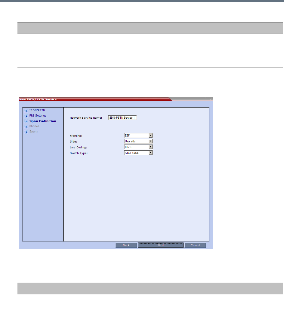
Defining ISDN/PSTN Network Services
Polycom®, Inc. 527
6Click Next.
The Span Definition dialog box is displayed:
7Define the following parameters:
Dial-out Prefix Enter the prefix that the PBX requires to dial out. Leave this field blank if a
dial-out prefix is not required.
The field can contain be empty (blank) or a numeric value between 0 and 9999.
Default: Blank
Span Definition
Field Description
Framing Select the Framing format used by the carrier for the network interface from the
list.
•For T1 spans, default is SFSF.
•For E1 spans, default is FEBE.
ISDN Service Settings
Field Description
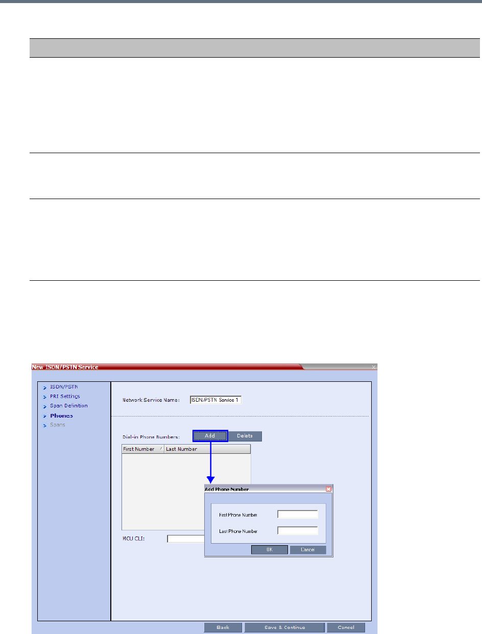
Defining ISDN/PSTN Network Services
Polycom®, Inc. 528
8Click Next.
The Phones dialog is displayed.
9To define dial-in number ranges click the Add button.
10 The Add Phone Number dialog box opens.
Side Select one of the following options:
•User side (default)
•Network side
•Symmetric side
Note: If the PBX is configured on the network side, then the Collaboration
Server unit must be configured as the user side, and vice versa, or both must be
configured symmetrically.
Line Coding Select the PRI line coding method from the list.
•For T1 spans, default is B8ZS.
•For E1 spans, default is HDB3.
Switch Type Select the brand and revision level of switch equipment installed in the service
provider’s central office.
•For T1 spans, default is AT&T 4ESS.
•For E1 spans, default is EURO ISDN.
Note: For T1 configurations in Taiwan, Framing must be set to ESF and Line
Coding to B8ZS.
Span Definition
Field Description
Defining ISDN/PSTN Network Services
Polycom®, Inc. 529
11 Define the following parameters:
12 Click OK.
The new range is added to the Dial-in Phone Numbers table.
13 To define additional dial-in ranges, repeat steps 8 to 10.
14 Enter the MCU CLI (Calling Line Identification).
In a dial-in connections, the MCU CLI indicates the MCU’s number dialed by the participant. In a
dial-out connection, indicates the MCU (CLI) number as seen by the participant
15 Click Save & Continue.
After clicking Save & Continue, you cannot use the Back button to return to previous configuration
dialog boxes.
The ISDN/PSTN Network Service is created and confirmed.
16 Click OK to continue the configuration.
The Spans dialog box opens displaying the following read-only fields:
ID – The connector on the ISDN/PSTN card (PRI1 - PRI12).
Slot – The media card that the ISDN/PSTN card is connected to (1 or 2)
Service – The Network Service to which the span is assigned, or blank if the span is not assigned
to a Network Service
Clock Source – Indicates whether the span acts as a clock source, and if it does, whether it acts
as a Primary or Backup clock source. The first span to synchronize becomes the primary clock
source.
State – The type of alarm: No alarm, yellow alarm or red alarm.
Phones Settings
Field Description
First Number The first number in the phone number range.
Last Number The last number in the phone number range.
•A range must include at least two dial-in numbers.
•A range cannot exceed 1000 numbers.
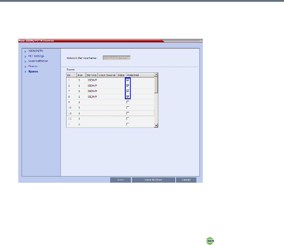
Defining ISDN/PSTN Network Services
Polycom®, Inc. 530
17 Attach spans to existing Network Services, by marking the appropriate check boxes in the Attached
field.
Each ISDN/PSTN card can support 7 E1 or 9 T1 PRI lines.
18 Click Save & Close.
Modifying an ISDN/PSTN Network Service
To Modify an ISDN/PSTN Network Service:
1In the RMX Management pane, click ISDN/PSTN Network Services ().
2In the ISDN/PSTN Network Services list, double-click the ISDN or right-click the ISDN entry and
select Properties.
The ISDN Properties dialog boxes are displayed. They are similar to the Fast Configuration
Wizard’s dialog boxes. For more information see Adding/Modifying ISDN/PSTN Network Services.
The following ISDN Properties can be modified:
PRI Settings
Net Specific
Dial-out Prefix
Span Definition
Framing
Side
Line Coding
Switch Type
Phones

Defining ISDN/PSTN Network Services
Polycom®, Inc. 531
Dial-in Phone Numbers
MCU CLI
Spans
Attached
All other ISDN Properties can only be modified by deleting the ISDN/PSTN network service and
creating a new PSTN service using the Fast Configuration Wizard. For more information, see
Adding/Modifying ISDN/PSTN Network Services.

Polycom®, Inc. 532
Network Security
System security can be enhanced by separating the Media, Signaling and Management Networks.
RealPresence Collaboration Server (RMX) 1500/4000
On the RealPresence Collaboration Server (RMX) 1500/4000, Media, Signaling and Management Networks
are physically separated to provide enhanced security. The Default IP Network Service and the
Management Network Service have been logically and physically separated from each other. In the IP
Network Service each IP address is assigned a physical port and media (RTP) inputs are routed directly to
a media card. This provides for a more secure network with greater bandwidth as each media card has its
own dedicated port. All signaling communications are processed on a single stack of the processor in the
Collaboration Server.
RealPresence Collaboration Server 1800
On the RealPresence Collaboration Server 1800 the Default IP Network Service and the Management
Network Service have been logically and physically separated from each other to provide enhanced
security. The Collaboration Server 1800 includes two LAN ports that can be used for separating the
management network from the signaling and media network or if Multiple Networks option is enabled, each
LAN port is used for signaling, media and management per Network Service.
RealPresence Collaboration Server (RMX) 2000
On the RealPresence Collaboration Server (RMX) 2000 a RTM LAN or RTM ISDN card is required to enable
the separation between the networks. By defining Multiple Network Services, a separate network can be
defined for each media card installed in the system.
For more information see Procedure 5: Enable Network Separation (RMX 2000) in the RealPresence
Collaboration Server (RMX) 1500/2000/4000 Deployment Guide for Maximum Security Environments.
Multiple Network Services
Media, signaling and management networks can be physically separated on the Collaboration Server
system to provide enhanced security. This addresses the requirement in an organization that different
groups of participants be supported on different networks. For example, some participants may be internal
to the organization while others are external.
Up to eight media and signaling networks can be defined for the RealPresence Collaboration Server (RMX)
4000, or four for the RealPresence Collaboration Server (RMX) 2000 and two for the RealPresence
Collaboration Server (RMX) 1500/1800. Multiple Networks are not supported by Collaboration Server
(RMX) 1800-0.
Multiple IP Network Services can be defined; up to two for each media and signaling network connected to
the Collaboration Server. The networks can be connected to one or several Media cards in the Collaboration
Server unit.
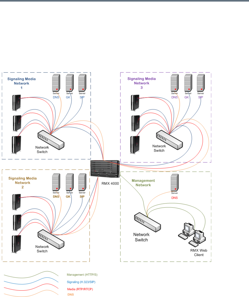
Network Security
Polycom®, Inc. 533
The Management Network is logically and physically separated from the media and signaling networks.
There can be one Management Network defined per Collaboration Server system.
Each conference on the Collaboration Server can host participants from the different IP Network networks
simultaneously.
The following figure shows the network topology with three different media and signaling networks and one
Management network connected to the Collaboration Server (RMX) 4000.
RealPresence Collaboration Server (RMX) 4000 - Multiple Networks Topology Sample
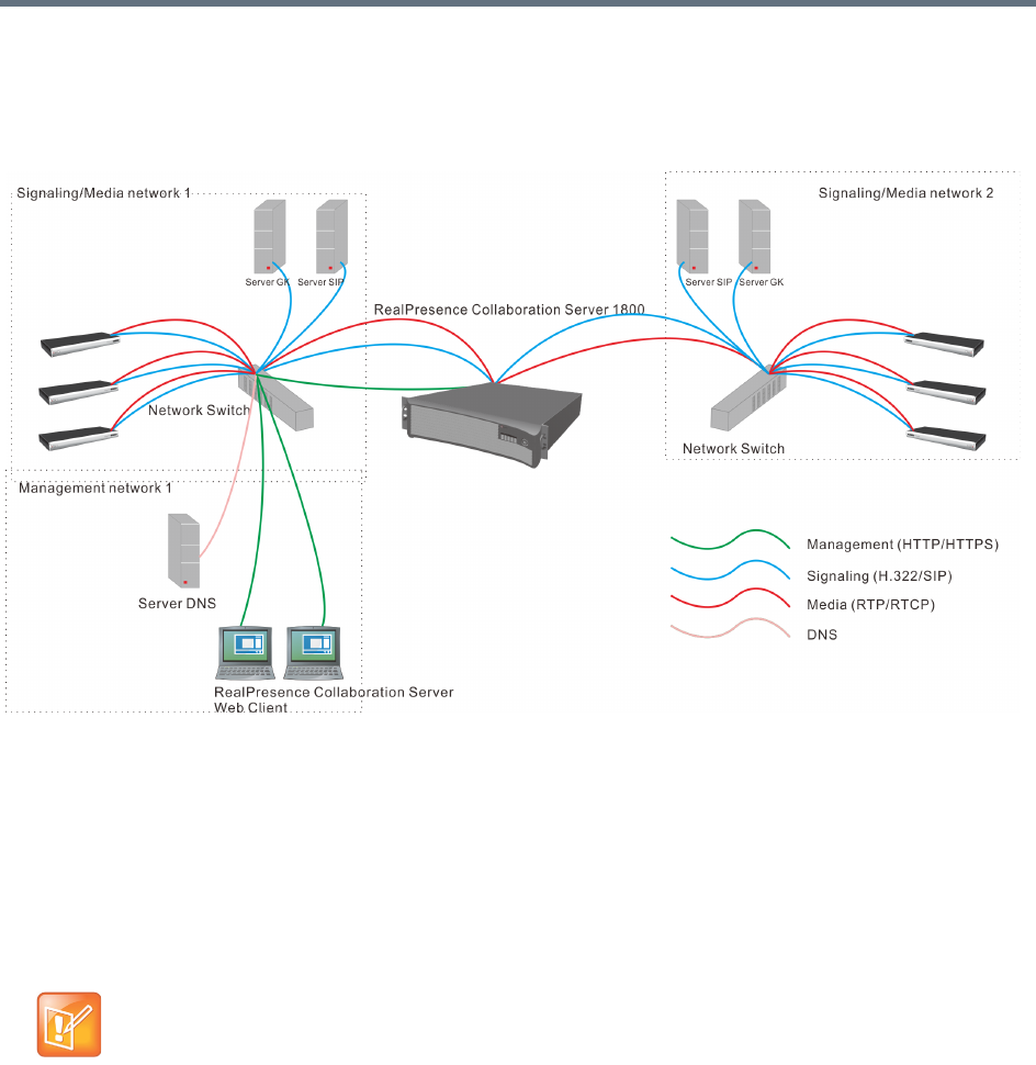
Network Security
Polycom®, Inc. 534
The following figure shows the network topology with two different media and signaling networks and one
Management network connected to the Collaboration Server (RMX) 1800.
RealPresence Collaboration Server (RMX) 1800 - Multiple Networks Topology Sample
Guidelines
●Multiple Services system mode is a purchasable option and it is enabled in the MCU license.
●Multiple Network Services are supported in MCUs with at least 1024MB memory only. MCU units with
memory of 512MB support only one IP Network Service.
●Multiple Services system mode is enabled when the system configuration flag
MULTIPLE_SERVICES is added and set to YES.
●Only IPv4 is supported for the definition of Multiple Network Services.
●When configuring Multiple Networks on the RealPresence Collaboration Server (RMX) 2000, the
RMX2000_RTM_LAN flag must be set to YES in addition to the MULTIPLE_NETWORKS=YES flag.
●Multiple Network Services are not supported with Microsoft ICE Environments in versions prior to
Version 7.8.
●Up to two Network Services, one per LAN port, can be associated with each Media card.
●An IP Network Service can be associated with one or several media cards. If more than one card is
associated with the same Network Service, the system routes the calls to the appropriate card
according to resource availability.
The MULTIPLE_SERVICE System Flag cannot be set to YES when IPv6 Addressing is enabled.

Network Security
Polycom®, Inc. 535
●On the RealPresence Collaboration Server (RMX) 2000/4000, both RTM ISDN or RTM LAN can be
used for Multiple Services configuration. However, if RTM ISDN is installed and used for Multiple
Services configuration, only one Network Service can be associated with the media card to which the
RTM/ISDN card is attached.
●On the RealPresence Collaboration Server (RMX) 1500, when Multiple Network Services option is
enabled, the two networks must differ in their subnet masks.
●On the RealPresence Collaboration Server (RMX) 1500 and 1800, LAN redundancy cannot be
enabled in parallel to Multiple Networks and the LAN_REDUNDANCY flag must be set to NO when
the Multiple Networks option is enabled.
●Participants on different networks can connect to the same conference with full audio, video and
content capabilities.
●Traffic on one network does not influence or affect the traffic on other networks connected to the same
MCU, unless they are connected to the same media card. If one network fails, it will not affect the
traffic in the other connected networks, unless they are connected to the same media card and the
card fails.
●Maximum number of services that can be defined per Collaboration Server platform:
●From Version 7.8 onwards, a DNS server can be specified for each IP Network Service and for the
Collaboration Server Management Network Service.
In the Network Services that do not include the DNS, use the IP addresses of the various devices
to define them in the Network Services.
●Participants are associated with a Network Service and use it resources as follows:
Dial-in participants - according to the network used to place the call and connect to the
Collaboration Server.
Dial-out participant - according to the Network Service selected during the participant properties
definition or during conference definition, according to the Network Service selected as default.
Maximum Number of Network Services per Collaboration Server System
MCU Total Media
Cards
Network Services
(Up to 2 per Media Card)
Management
Services
Network Services
that Include ICE
(1 / Media Card)
1500 1 Up to 2 1 1
1800
(Excluding
1800-0)
3 (DSP Cards) Up to 2
11
2000 2 Up to 4 when using 2 RTM LAN
cards.
Less when using a combination
of RTM ISDN and RTM LAN, or
2 RTM ISDN cards.
12
4000 4 Up to 8 when using 4 RTM LAN
cards.
Less when using up to 2 RTM
ISDN cards and the remaining
RTM LAN cards.
14

Network Security
Polycom®, Inc. 536
●Recording Links use the default Network Service to connect to conferences, therefore the recording
system must be defined on the default network to enable the recording.
Resource Allocation and Capacity
The Video/Voice Port Configuration (Collaboration Server 1500/20000/4000 in MPMx Card Configuration
Mode only) and the Resolution Configuration settings are configured per MCU and affect the resource
capacity of the MCU. They are reflected in the port gauges displayed on the Collaboration Server
management application’s main screen. In Multiple Networks mode, the overall resources are divided
between the Network Services. However, the port gauges do not reflect the resource availability per
Network Service. For more information see Resource Capacity.
First Time Installation and Configuration
First Time Installation and Configuration of the RealPresence Collaboration Server (RMX)
1500/1800/2000/4000 consists of the following procedures:
1Preparations:
Gather Network Equipment and Address Information Get the information needed for integrating
the Collaboration Server into the local network for each of the networks that will be connected to
the Collaboration Server.
Unpack the Collaboration Server.
Modify the Management Network parameters on the USB Key.
2Hardware Installation and Setup:
Mount the Collaboration Server in a rack.
Connect the necessary cables.
3First Entry Power-up and Configuration:
Power up the Collaboration Server.
Register the Collaboration Server.
Connect to the Collaboration Server.
Configure the Default IP Network Service.
Configure the ISDN/PSTN Network Service.
Modify the required System Flag to enable Multiple Services and reset the MCU.
4Add the required IP Network Services to accommodate the networks connected to the Collaboration
Server.
5Select a Network Service to act as default for dial out and gateway calls for which the Network
Service was not selected.
6Place several calls and run conferences to ensure that the system is configured correctly.
For details see First Time Installation and Configuration in the Polycom RealPresence Collaboration Server
(RMX) 1500/1800/2000/4000 Getting Started Guide.

Network Security
Polycom®, Inc. 537
Upgrading to Multiple Services
1Gather Network Equipment and Address Information for each of the networks that will be connected
to the Collaboration Server unit. For a list of required address, see the Polycom RealPresence
Collaboration Server (RMX) 1500/1800/2000/4000 Getting Started Guide, Gather Network
Equipment and Address Information.
2Upgrade to the new version and install the activation key that contains the Multiple Services license
as described in the RealPresence Collaboration Server (RMX) 1500/1800/2000/4000 Release
Notes. .
3Place several calls and run conferences to ensure that the system upgrade was completed
successfully.
4Modify the required System Flag to enable Multiple Services, DO NOT reset the MCU yet.
5Connect the additional network cables to the Collaboration Server and change existing connections
to match the required configuration as described in the appropriate RealPresence Collaboration
Server (RMX) Hardware Guide.
At this point, the Management Network can be modified to match the required local network settings
.
6Reset the MCU.
7Connect to the MCU and add the required IP Network Services to accommodate the networks
connected to the Collaboration Server unit.
8Select a Network Service to act as default for dial out and gateway calls for which the Network
Service was not selected.
9Place several calls and run conferences to ensure that the system is configured correctly.
Gather Network Equipment and Address Information - IP Network
Services Required Information
It is important that before connecting multiple networks and implementing Multiple Services in the
Collaboration Server, that you obtain the information needed to complete the IP Network Service
configuration for each connected network from your network administrator.
If the RealPresence Collaboration Server (RMX) 2000 you are upgrading does not include RTM
ISDN or RTM LAN cards, you must install at least one RTM LAN card to enable the definition of
multiple Network Services. If no RTM ISDN or RTM LAN cards are installed, the RealPresence
Collaboration Server (RMX) 2000 works in a single Network Service mode and an alarm is issued by
the system. For more details about the installation of RTM LAN cards, see the RealPresence
Collaboration Server (RMX) 2000 Hardware Guide.
Network Equipment and Address Information per IP Network Service
Parameter Note
Signaling Host IP address
Media Board IP address (MPM 1)
Media Board IP address (MPM 2)
RealPresence Collaboration Server (RMX) 2000/4000 only
If more than one media card is
associated with this Network Service
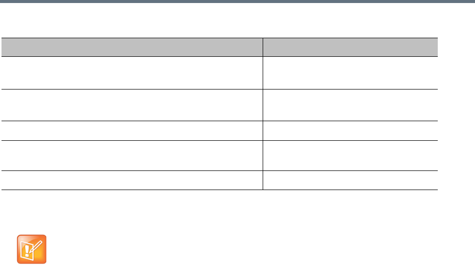
Network Security
Polycom®, Inc. 538
RealPresence Collaboration Server (RMX) Hardware Installation
Media Board IP address (MPM 3)
RealPresence Collaboration Server (RMX) 4000 only
If more than one media card is
associated with this Network Service
Media Board IP address (MPM 4)
RealPresence Collaboration Server (RMX) 4000 only
If more than one media card is
associated with this Network Service
Gatekeeper IP address (optional)
DNS IP address (optional) Only one DNS can be defined for the
entire Network topology
SIP Server IP address (optional)
When connecting the LAN cables of the various networks to the Collaboration Server it is
recommended to use a color system to differentiate between the networks, for example, using
colored cables.
Network Equipment and Address Information per IP Network Service
Parameter Note
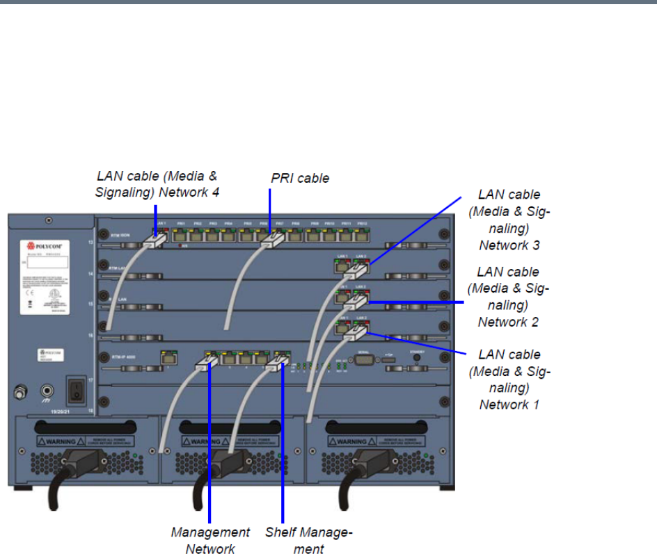
Network Security
Polycom®, Inc. 539
RealPresence Collaboration Server (RMX) 4000 Multiple Services Configuration
RealPresence Collaboration Server (RMX) 4000 Rear Panel with LAN and PRI cables shows the cables
connected to the RealPresence Collaboration Server (RMX) 4000 rear panel, when one RTM ISDN and
three RTM LAN cards are installed providing IP and ISDN connectivity. The RTM ISDN card can be used
for both ISDN and IP calls and only one IP network Service is associated with each RTM/LAN card.
RealPresence Collaboration Server (RMX) 4000 Rear Panel with LAN and PRI cables
In this case, up to four different IP Network Services can be defined - one for each RTM LAN/RTM ISDN
cards installed in the system.
If two LAN ports per each installed RTM LAN card are used, up to three additional Network Services can be
defined, bringing it to a total of up to 7 IP Network Services.
Several cards can be assigned to the same IP Network Service. The definition of the network services
attached to the Collaboration Server unit and which cards are assigned to each network service is defined
in the IP Network Service.
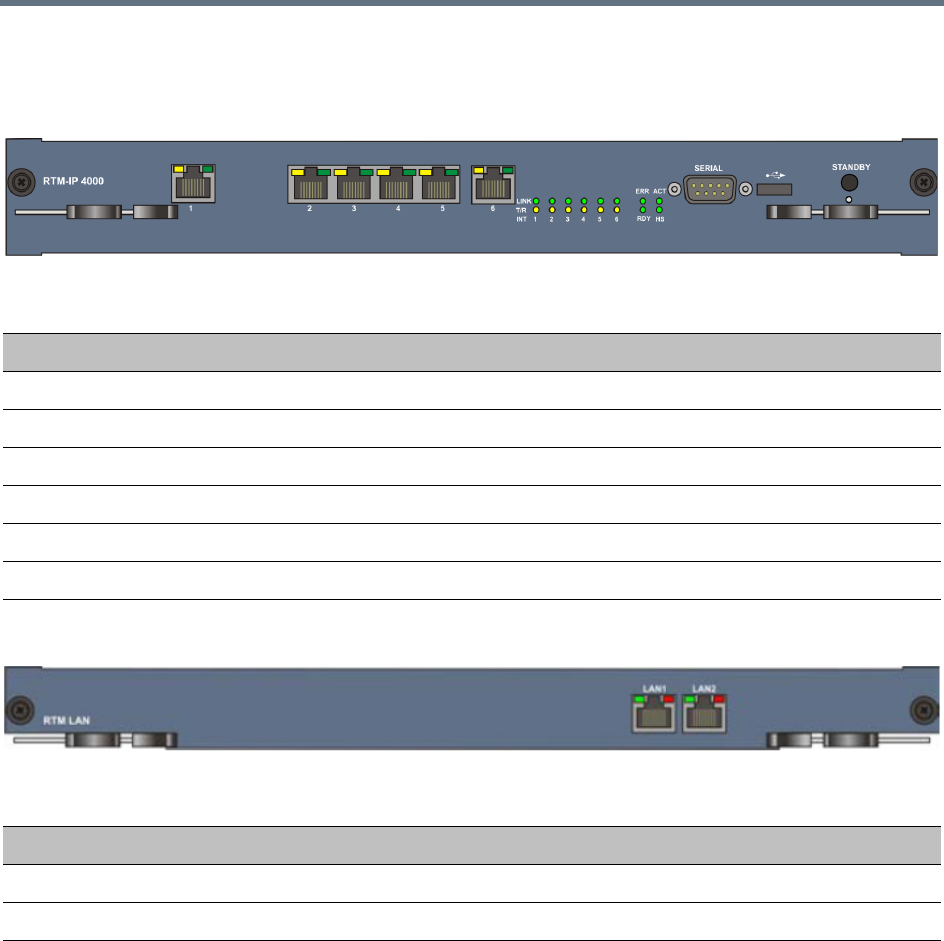
Network Security
Polycom®, Inc. 540
Connecting the cables to the RTM IP 4000
The following cables are connected to the RTM IP on the rear panel of the RealPresence Collaboration
Server (RMX) 4000.
Connecting the cables to the RTM LAN
RealPresence Collaboration Server (RMX) 2000 Multiple Services Configuration
If one LAN port per RTM ISDN/ RTM LAN card is used, up to two different IP Network Services can be
defined - one for each installed RTM LAN/RTM ISDN cards.
If two LAN ports per each installed RTM LAN card are used, up to four Network Services can be defined.
RealPresence Collaboration Server (RMX) 2000 Rear Panel with RTM LAN Cables shows the cables
connected to the RealPresence Collaboration Server (RMX) 2000 rear panel, when two RTM LAN cards are
installed providing IP connectivity. In this case, only one IP network Service can be associated with each
RTM LAN card.
LAN Connections to the RTM IP
RTM IP Port Description
LAN 1 Modem
LAN 2 Management
LAN 3 –
LAN 4 –
LAN 5 –
LAN 6 Shelf Management
LAN Connections to the RTM LAN
RTM LAN Port Description
LAN 1 Signaling and Media - additional (second) Network Service
LAN 2 Signaling and Media - existing (first) Network Service
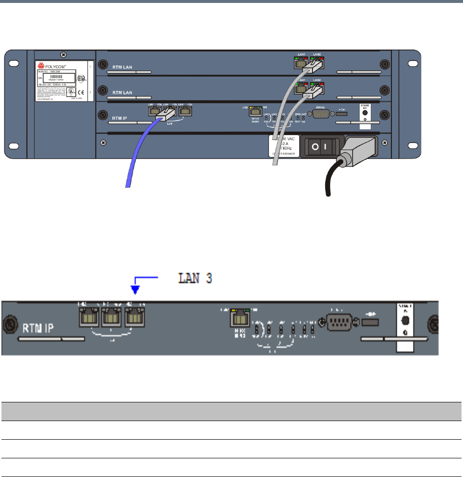
Network Security
Polycom®, Inc. 541
RealPresence Collaboration Server (RMX) 2000 Rear Panel with RTM LAN Cables
Connecting the cables to the RTM IP
The following cables are connected to the RTM IP on the rear panel of the RealPresence Collaboration
Server (RMX) 2000.
LAN Connections to the RTM IP
RTM IP Port Description
LAN 1 –
LAN 2 Management
LAN 3 Modem
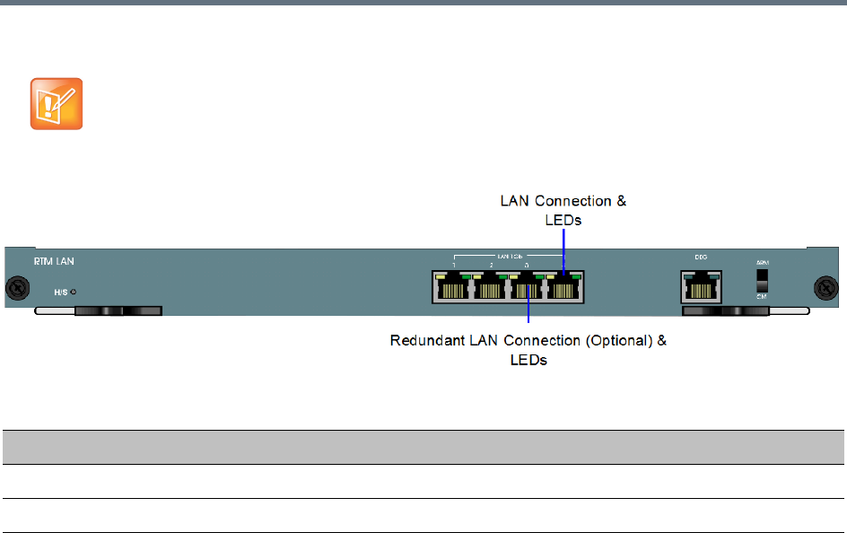
Network Security
Polycom®, Inc. 542
Connecting the cables to the RTM LAN
RealPresence Collaboration Server (RMX) 1800 Multiple Services Configuration
Up to two media and signaling networks can be defined for the RealPresence Collaboration Server (RMX)
1800. Each of these networks can be assigned a different IP Network Services (Multiple IP Network
Services).
If RTM LAN or RTM ISDN cards are not installed on the Collaboration Server, they must be installed
before connecting the additional network cables for media and signaling.
LAN Connections to the RTM LAN
RTM IP Port Description
LAN 1 Signaling and Media - second Network Service (optional)
LAN 2 Signaling and Media - first Network Service (optional)
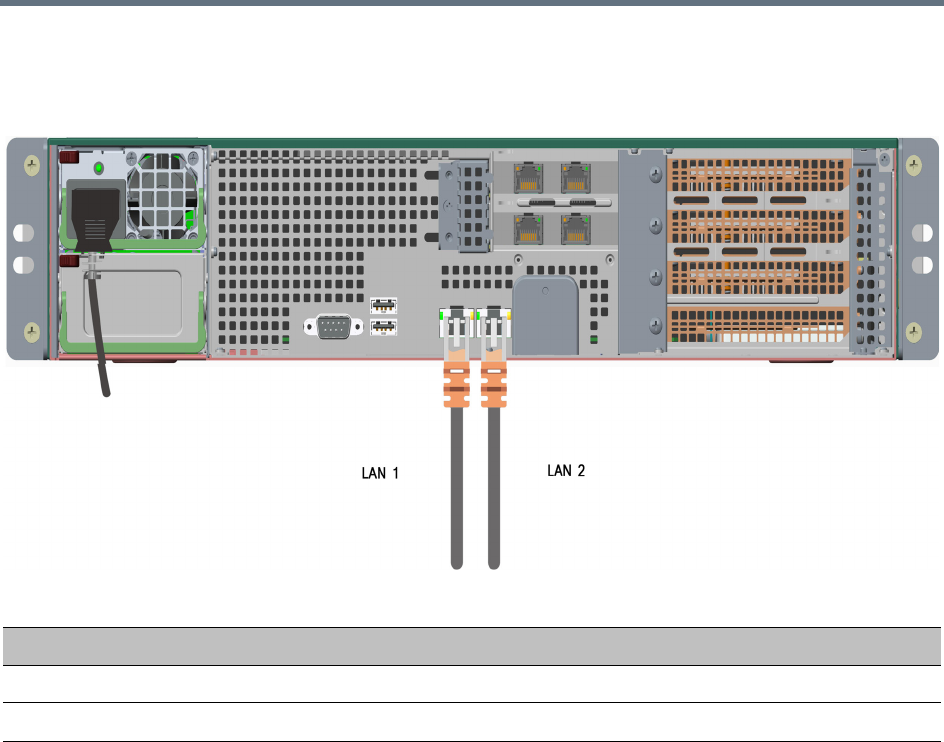
Network Security
Polycom®, Inc. 543
Connecting the cables to the RealPresence Collaboration Server 1800
Two LAN cables are connected to the LAN ports on the rear panel of the RealPresence Collaboration Server
1800:
RealPresence Collaboration Server (RMX) 1500 Multiple Services Configuration
Up to two media and signaling networks can be defined for the RealPresence Collaboration Server (RMX)
1500. Each of these networks can be assigned a different IP Network Services (Multiple IP Network
Services).
LAN Connections to the IP ports
IP Port Description
LAN 1 Management, media and signaling for Network Service 1.
LAN 2 Media and signaling for Network Service 2.
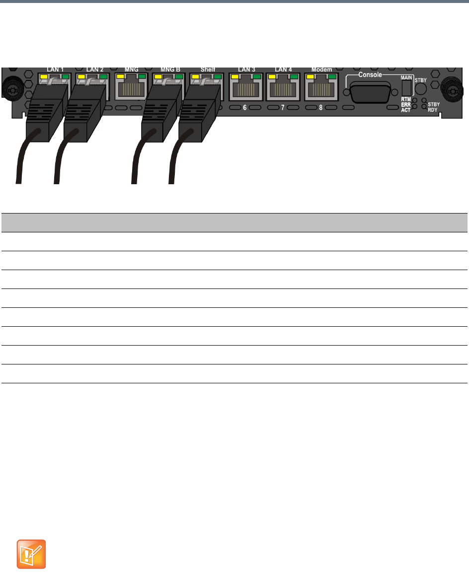
Network Security
Polycom®, Inc. 544
Connecting the cables to the RTM IP 1500
The following cables are connected to the RTM IP on the rear panel of the RealPresence Collaboration
Server (RMX) 1500:
Collaboration Server Configuration
Once the network cables are connected to the Collaboration Server, you can modify the default IP Network
Service and add additional Network Services.
System Flags and License Settings
The MULTIPLE_SERVICES System Flag determines whether the Multiple Services option will be activated
once the appropriate license is installed. Possible Values: YES / NO Default: NO
This flag must be manually added to the system configuration and set to YES to enable this option. For more
information see .
LAN Connections to the RTM IP
RTM IP Port Description
LAN 1 Media and signaling - additional (second) Network Service
LAN 2 Media and signaling - existing (first) Network Service
MNG –
MNG B Management
Shelf Shelf Management
LAN 3 –
LAN 4 –
Modem Modem
If the MULTIPLE_SERVICES System Flag is set to YES and no RTM ISDN or RTM LAN card is
installed in the RealPresence Collaboration Server (RMX) 2000, an Active Alarm is displayed.

Network Security
Polycom®, Inc. 545
IP Network Service Definition
Use this procedure to define Network Services in addition to the Network Service already defined during
first entry installation and configuration. Each of the defined Network Service can be associated with one or
more media cards installed in the system (depending on the system type).
Once a media card is associated with a Network Service it cannot be associated with another network
service.
If the values or either of the MULTIPLE_SERVICES or V35_ULTRA_SECURED_SUPPORT
System Flags are changed from YES to NO, the defined IP Network Services are not displayed in
the IP Network Services list pane: they are, however, saved in the system.
If either of the flag values are changed back to YES, the saved defined IP Network Services will be
displayed.

Network Security
Polycom®, Inc. 546
To add new/additional Network Services:
1In the Device Management pane, click IP Network Services ().
2In the Network Services list toolbar, click the Add Network Service button.
The New IP Service - Networking IP dialog box opens.
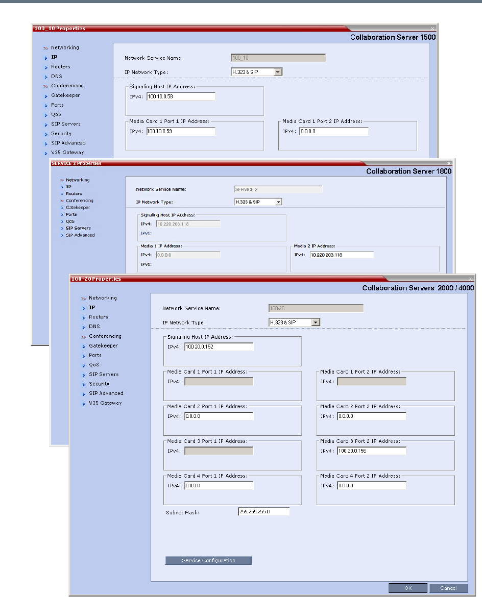
Network Security
Polycom®, Inc. 547
3Define the following fields:
Network Security
Polycom®, Inc. 548
IP Network Service - IP Parameters
Field Description
Network Service Name Enter the IP Network Service name.
Note: This field is displayed in all IP Signaling dialog boxes and can contain
character sets that use Unicode encoding.
IP Network Type Select the IP Network environment. You can select:
• H.323 - For an H.323-only Network Service.
•SIP - For a SIP-only Network Service.
• H.323 & SIP - For an integrated IP Service. Both H.323 and SIP participants
can connect to the Collaboration Server using this service.
Note: This field is displayed in all Default IP Service tabs.
Signaling Host IP
Address
Enter the address to be used by IP endpoints when dialing into the
Collaboration Server using this Network Service.
Dial out calls of participants to whom this network service will be assigned are
initiated from this address.
This address is used to register the Collaboration Server with a Gatekeeper or a
SIP Proxy server residing on this network.
Media Card 1 Port 1 IP
Address
Media Card 1 Port 2 IP
Address 2
If only one network is connected to this media card, it is enough to assign one
media card to this Network Service. In such a case, enter one IP address for the
media card according to the LAN Port used for the connection.
If each of the LAN ports on one media card is used with two different networks,
each port is assigned to its own Network Service. In such a case, enter the IP
address of the port to be assigned to this Network Service.
A LAN port that is already assigned to a different Network Service, displays the
IP Address of the assigned port and it cannot be assigned to this Network
Service (it is disabled).
Network Security
Polycom®, Inc. 549
Media Card 2 Port 1 IP
Address
Media Card 2 Port 2 IP
Address
(RealPresence
Collaboration Server
(RMX) 2000/4000)
If only one network is connected to this media card, it is enough to assign one
media card to this Network Service. In such a case, enter one IP address for the
media card according to the LAN Port used for the connection, as provided by
the network administrator.
If each of the LAN ports on one media card is used with two different networks,
each port is assigned to its own Network Service. In such a case, enter the IP
address of the port to be assigned to this Network Service.
Notes:
•LAN Ports/Media cards that are already associated with another Network
Service cannot be associated with this Network Service.
•You can define a Network Service without assigning media cards to it.
•To change the assignment of a card from one service to another, the card
must first be removed from the service to which it is assigned prior to its
assignment to another service.
RealPresence Collaboration Server (RMX) 2000: If one card was already
assigned to another service, only one additional card can be assigned to this
service.
RealPresence Collaboration Server (RMX) 4000: Depending on the number of
media cards installed in the system, you can assign up to 4 media cards to this
network service provided that they are not assigned to any other Network
Service.
Media Card 3 Port 1 IP
Address/
Media Card 3 Port 2 IP
Address
(RealPresence
Collaboration Server
(RMX) 4000)
Media Card 4 Port 1 IP
Address
Media Card 4 Port 2 IP
Address
(RealPresence
Collaboration Server
(RMX) 4000)
Subnet Mask Enter the subnet mask of the Collaboration Server in that network service.
Default value: 255.255.255.0.
IP Network Service - IP Parameters
Field Description
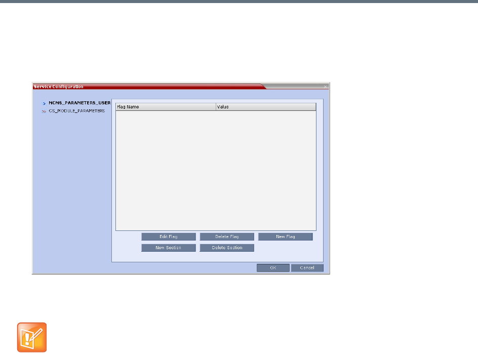
Network Security
Polycom®, Inc. 550
4 Optional. Some system flags can be defined per Network Service, depending on the network
environment.
To modify these flags, click the Service Configuration button.
The Service Configuration dialog box opens.
All the flags must be manually added to this dialog box. For a detailed description of the flags and
how to add them, see .
The following flags can be defined per service:
ALLOW_NON_ENCRYPT_PARTY_IN_ENCRYPT_CONF
ENABLE_H239
SIP_ENABLE_FECC
ENABLE_CLOSED_CAPTION
ALLOW_NON_ENCRYPT_RECORDING_LINK_IN_ENCRYPT_CONF
NUMERIC_CONF_ID_LEN
NUMERIC_CONF_ID_MIN_LEN
NUMERIC_CONF_ID_MAX_LEN
ENABLE_CASCADED_LINK_TO_JOIN_WITHOUT_PASSWORD
MAX_CP_RESOLUTION
QOS_IP_AUDIO
QOS_IP_VIDEO
QOS_IP_SIGNALING
ENABLE_CISCO_GK
SIP_FREE_VIDEO_RESOURCES
Flags defined per Network Service override their general definition in the System Configuration.
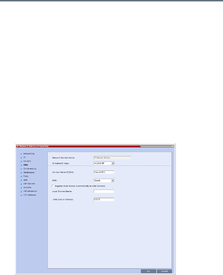
Network Security
Polycom®, Inc. 551
FORCE_CIF_PORT_ALLOCATION
MS_ENVIRONMENT
SIP_FAST_UPDATE_INTERVAL_ENV
SIP_FAST_UPDATE_INTERVAL_EP
H263_ANNEX_T
H239_FORCE_CAPABILITIES
MIX_LINK_ENVIRONMENT
IP_LINK_ENVIRONMENT
FORCE_STATIC_MB_ENCODING
FORCE_RESOLUTION
SEND_WIDE_RES_TO_IP
DISABLE_WIDE_RES_TO_SIP_DIAL_OUT
SEND_SIP_BUSY_UPONRESOURCE_THRESHOLD
5Click the Routers tab.
6Define the routers used in this network and that are other than the routers defined in the
Management Network. The field definitions of the Routers tab are the same as for the Default
Management Network. For more information see Default Management Network Service – Routers.
7Click the DNS tab.

Network Security
Polycom®, Inc. 552
8Modify the following fields:
9Click the Gatekeeper tab.
10 Define the Primary and Alternate Gatekeepers and at least one Alias for this network Service. The
field definitions of the Gatekeeper tab are the same as for the Default IP Network Service. For more
information see Default IP Service – Conferencing – Gatekeeper Parameters.
11 To view or modify the port settings, click the Ports tab.
Settings in the Ports tab allow specific ports in the firewall to be allocated to multimedia conference
calls. If required, defined the ports to be used multimedia conference calls handled by this Network
Service. The field definitions of the Ports tab are the same as for the Default IP Network Service.
For more information see Default IP Service – Conferencing – Ports Parameters.
Default Management Network Service – DNS
Field Description
Service Host Name Enter the host name of this network Service. Each Network Service must have a
unique Host Name otherwise an error message is displayed.
DNS Select:
•Off – If no DNS server is used in this network.
•Specify – To enter the IP address of the DNS server used by this network
service.
Notes:
•The IP address field is enabled only if Specify is selected.
•In both Standard Security and Ultra Secure Modes:
•A DNS can be configured for the Management Network Service that is
defined and the IP Network Service.
•If a Multiple Services Licence is installed, a DNS can be configured for each
additional IP Network Service that is defined.If the DNS field in the IP
Network Service is set to Specify and the DNS is not configured or disabled,
the DNS configured for the Management Network will be used.
•When upgrading from a version that does not support a DNS per IP Network
Service, the DNS configured for the Management Network will be used.
Register Host Names
Automatically to DNS
Servers
Select this option to automatically register this Network Service Signaling
Host with the DNS server.
Local Domain Name Enter the name of the domain for this network service.
DNS Server Address Enter the static IP address of the DNS server that is part of this network.
In Multiple Services mode, an Alias must be defined for the specified gatekeeper.
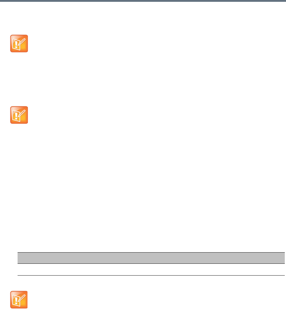
Network Security
Polycom®, Inc. 553
12 If required, click the QoS tab.
The Collaboration Server’s implementation of QoS is defined per Network Service, not per endpoint.
The field definitions of the QoS tab are the same as for the Default IP Network Service. For more
information see Default IP Service – Conferencing – QoS Parameters.
13 Click the SIP Servers tab.
14 Define the Primary and Alternate SIP Server for this network Service.
The field definitions of the SIP Servers tab are the same as for the Default IP Network Service. For
more information see Default IP Network Service – SIP Servers.
15 Click the Security tab.
The field definitions of the Security tab are the same as for the Default IP Network Service. For more
information see Default IP Network Service – Security (SIP Digest).
16 To configure the ICE environment, click the SIP Advanced tab.
17 Modify the following fields:
18 Click the OK button.
The new Network Service is added to the IP Network Services list pane.
The routers must support QoS in order for IP packets to get higher priority.
•Starting with Version 7.1, Registration of conferencing entities with the SIP Servers was moved
to the conferencing entities and is defined in the Conference Profile.
•If Microsoft Office Communications or Lync server are part of this network service, a certificate
must be created for this network service. If each network connected to the Collaboration Server
includes Microsoft Office Communications or Lync server, separate certificates must be created
and sent to the Collaboration Server for each of these networks.
•If the Network Service does not include a DNS, you must use the IP address of the SIP Server
instead of its name.
Default IP Network Service – SIP Advanced
Field Description
ICE Environment Select MS (for Microsoft ICE implementation) to enable the ICE integration.
For more information, see
LAN Redundancy
.

Network Security
Polycom®, Inc. 554
Setting a Network Service as Default
The default Network Service is used when no Network Service is selected for the following:
●Dial out participants
●Reserving resources for participants when starting an ongoing conference
●Gateway calls
In addition, the Signaling Host IP address and the MCU Prefix in GK displayed on the Collaboration Server
Web Client main screen are taken from the default H.323 Network Service.
One IP Network Service can be defined as default for H.323 connections and another Network Service as
default for SIP connections. If the IP Network Service supports both H.323 and SIP connections, you can
set the same Network Service as default for both H.323 and SIP, or for H.323-only or for SIP-only.
To designate an IP Network Service as the default IP Network Service:
1In the Device Management pane, click IP Network Services ().
2In the Network Services list pane right-click the IP Network Service to be set as the default, and
then click Set As H.323 Default, or Set As SIP Default.
The next time you access this menu, a check mark is added next to the network service type to
indicate its selection as default.
To set this IP Network Service for both H.323 and SIP connections, repeat step 2 and select the
option you need.
The following icons are used to indicate the default IP Network Service type:
Ethernet Settings
The Collaboration Server is set to automatically identify the speed and transmit/receive mode of each LAN
ports located on the RTM LAN or RTM ISDN cards that are added to the system. These port settings can
be manually configured if the specific switch requires it, via the Ethernet Settings dialog box.
Default IP Network Service Icons
Icon Description
This Network Service supports both SIP and H.323 connections and is
designated as default for both SIP and H.323 connections.
This Network Service supports both SIP and H.323 connections and is
designated as default for H.323 connections.
This Network Service supports both SIP and H.323 connections and is
designated as default for SIP connections.
This Network Service supports only H.323 connections and is set as default for
H.323 connections.
This Network Service supports only SIP connections and is set as default for
SIP connections.
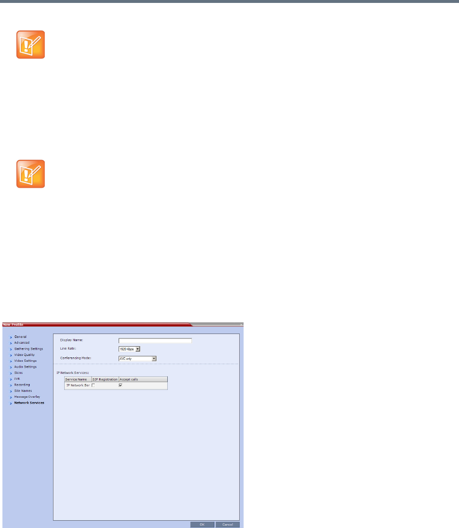
Network Security
Polycom®, Inc. 555
Signaling Host IP Address and MCU Prefix in GK Indications
The Collaboration Server Web Client displays the Signaling Host IP Address and MCU Prefix in GK
parameters as defined in the Default H.323 Network Service.
Video/Voice Port and Resolution Configuration
These configurations are set for the system and are applied to all the Network Services.
Conference Profile
Registration of conferencing entities such as ongoing conferences, Meeting Rooms, Entry Queues, SIP
Factories and Gateway Sessions with SIP servers is done per conferencing entity. This allows better control
on the number of entities that register with each SIP server by selecting for each of the conferencing entities
whether it will register with the SIP server.
The registration is defined in the Conference Profile - Network Services tab.
In the IP Network Services table, the system lists all the defined Network Services (one or several
depending on the system configuration).
●To register the conferencing entity to which this profile is assigned to a Network Service, in the
Registration column click the check box of that Network Service.
RealPresence Collaboration Server (RMX) 1500: The Port numbers displayed in the dialog box
do not reflect the physical Port numbers as labeled on the RealPresence Collaboration Server
(RMX) 1500 MCU.
This section is applicable to Collaboration Server with MPMx cards only.
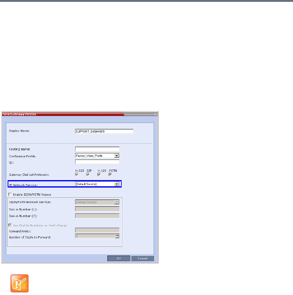
Network Security
Polycom®, Inc. 556
●You can also prevent dial in participants from connecting to that conferencing entities when
connecting via a Network Service.
In the Accept Calls column, clear the check box of the Network Service from which calls cannot
connect to the conference.
Gateway Profiles
To enable the Collaboration Server to call the destination endpoint/MCU via IP connection, the Network
Service for the call must be selected in the Gateway Profile dialog box.
The Network Service set as default is used if no other Network Service is selected.
If the same Network Service is used for H.323 and SIP calls, the Network Service Environment must
include both H.323 and SIP settings.
Note: Gateway Functionality
Gateway functionality is not supported by Collaboration Server (RMX) 1800-0.
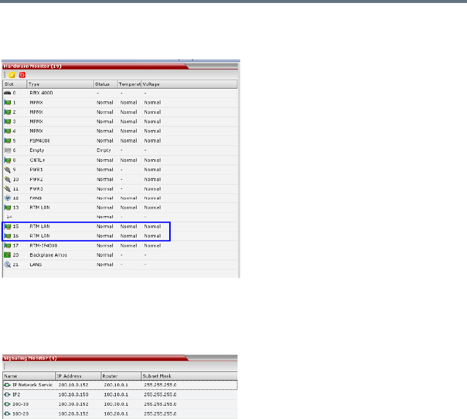
Network Security
Polycom®, Inc. 557
Hardware Monitor
The Hardware Monitor pane includes the status of the LAN ports on the RTM LAN cards.
Signaling Monitor
The Signaling Monitor pane includes the list of the IP Network Services defined in the system - up to two
in the RealPresence Collaboration Server (RMX) 1500/1800/2000 and up to four in the RealPresence
Collaboration Server (RMX) 4000. Double-clicking a Network Service, displays it properties and status.
Conferencing
Each conference on the Collaboration Server can host participants from the different IP Network networks
simultaneously.
Defining Dial Out Participants
When defining dial out participants, you can select the Network Service to place the call according to the
network to which the endpoint pertains. If the endpoint is located on a network other than the selected
network, the participant will not be able to connect.
If no Network is selected, the system uses the IP Network Service selected for reserving the conference
resources, and if none is set for the conference it uses the Network Service set as default.
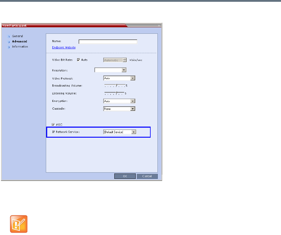
Network Security
Polycom®, Inc. 558
The IP Network Service is selected in the New Participant - Advanced dialog box.
Reserving Video Resources for a Conference
When defining a new ongoing conference or a conference reservation, you can select the Network Service
that will be used to reserve the required resources. If no Network Service is selected, the default Network
Service is used. Therefore, make sure that not all conferences are reserving resources from the same
Network Service, otherwise you may run out of resources for that Network Service.
This section is applicable only for Collaboration Servers 1500/2000/4000.
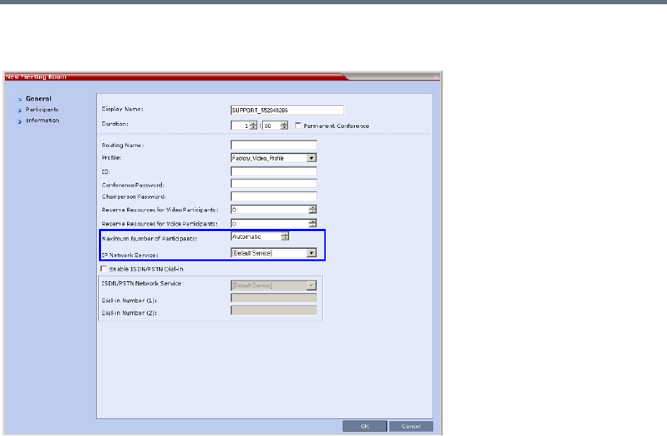
Network Security
Polycom®, Inc. 559
The IP Network Service is selected in the New Conference/New Meeting Room/New Reservation -
General dialog box.
Monitoring Conferences
The Conference Properties - Network Services dialog box shows for each Network Service with which
Network Service’s SIP proxy the conference should be registered and if the dial in call will be connected to
the conference.
In the Participant pane, a new column - Service Name was added, indicating the name of Network Service
used for the participant’s connection.
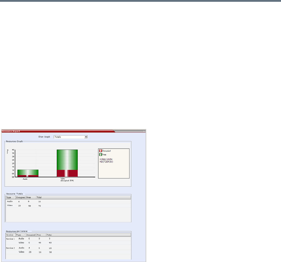
Network Security
Polycom®, Inc. 560
Resource Report
The Resource Report displays a graph of the MCU’s total resource usage as well as a graph of the MCU’s
total resource usage. When Multiple Network Services are active, an additional table of resource usage per
network service is displayed.
Video resource allocations are reported in AVC HD720p30 units. The same amounts of system resources
are allocated to Voice (Audio) participants, as those allocated to CIF Video participants.
The user can select a view of either resource usage Totals (default) or resource usage per Network Service.
For Collaboration Servers 1500 and 2000/4000 with MPMx media cards both Video and Audio resource
usage is displayed.
For Collaboration Servers 1800 and 2000/4000 with MPMRx media cards there is no differentiation
between Video and Voice (Audio) resource usage.
Resource Report - Collaboration Servers 1500 and 2000/4000 with MPMx Cards
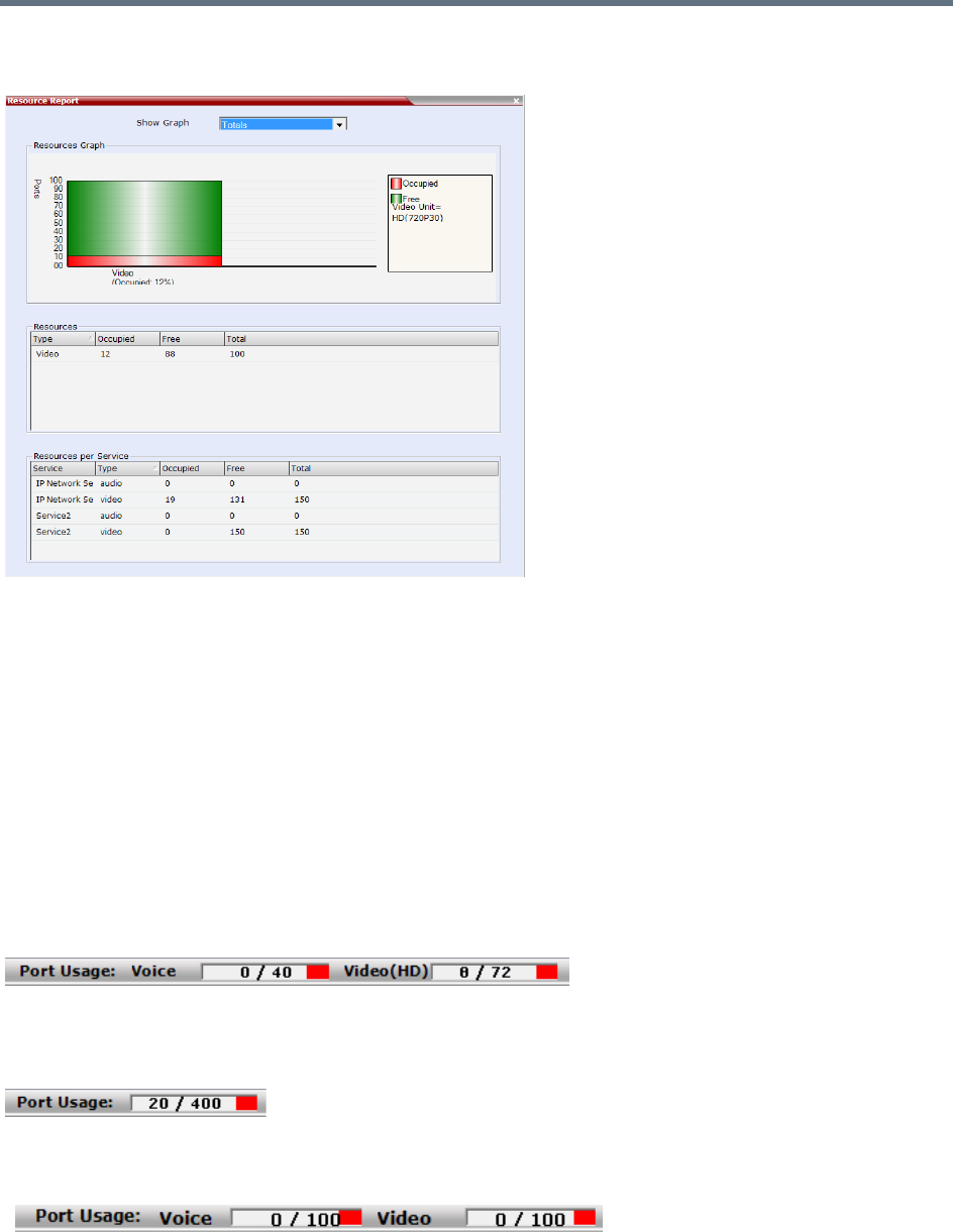
Network Security
Polycom®, Inc. 561
Resource Report - Collaboration Servers 1800 and 2000/4000 with MPMRx Cards
Port Usage Gauges
Collaboration Servers 1500 and 2000/4000 with MPMx media cards display port usage for Voice (Audio)
and Video separately.
Collaboration Servers 1800 and 2000/4000 with MPMRx media cards do not differentiate between Video
and Voice (Audio) resource usage and display a single port usage gauge.
The Port Gauge(s) show the total resource usage for the Collaboration Server and not per Network Service.
So it may not be an accurate representation of the availability of resources for conferencing, as one Network
Service may run out of available resources while another Network Service may have all of it resources
available. In such a case, the port gauge(s) may show that half of the system resources are available for
conferencing, while calls via the Network Service with no available resources will fail to connect.
Port Usage Gauges - Collaboration Servers 1500 and 2000/4000 with MPMx Cards
Port Usage Gauge - Collaboration Servers 2000/4000 with MPMRx Cards
Port Usage Gauge - Collaboration Server 1800 with MPMx Cards
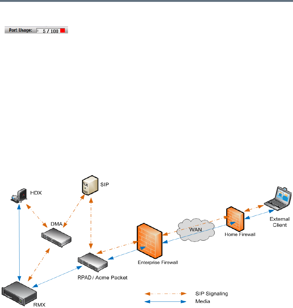
Network Security
Polycom®, Inc. 562
Port Usage Gauge - Collaboration Server 1800 with MPMRx Cards
NAT (Network Address Translation) Traversal
NAT Traversal is a set of techniques enabling participants behind firewalls to connect to conferences,
hosted on the Collaboration Server, remotely using the internet.
All signaling and media for both SIP and H.323 will be routed through an SBC. The following SBC
environments are supported:
●SAM - a Polycom SBC
●Acme Packet - a 3rd party SBC
●VBP - Polycom Video Border Proxy
Deployment Architectures
The following NAT Traversal topologies are given as examples. Actual deployments will depend on user
requirements and available infrastructure:
Remote Connection Using the Internet
The following Remote Connection call flow options are supported:
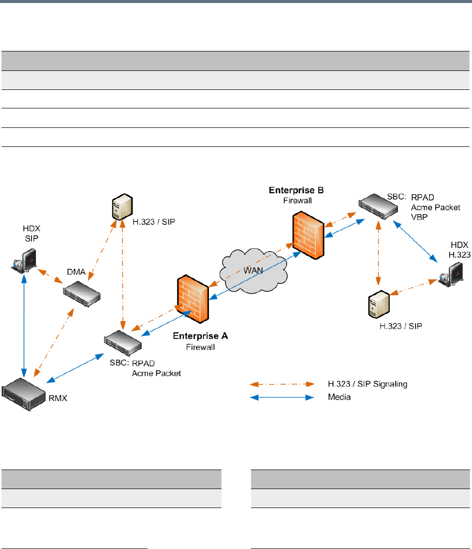
Network Security
Polycom®, Inc. 563
Business to Business Connections
The following Business to Business connection call flow options are supported:
Remote Connections
Enterprise Client
Environment Registered SBC
SIP / H.323 Yes SAM / Acme Packet
SIP / H.323 No SAM / Acme Packet
SIP / H.323 No SAM Only
Business to Business Connections
Enterprise A Client Enterprise B Client
Environment Registered SBC SBC Registered Environment
H.323 Yes RealPresence
Access
Director
RealPresence
Access
Director
Yes H.323
H.323 Yes VBP Yes H.323
Network Security
Polycom®, Inc. 564
FW (Firewall) NAT Keep Alive
The Collaboration Server can be configured to send a FW NAT keep alive message at specific Intervals for
the RTP, UDP and BFCP channels.
This is necessary because port mappings in the firewall are kept open only if there is network traffic in both
directions. The firewall will only allow UDP packets into the network through ports that have been used to
send packets out.
By default the Collaboration Server sends a FW NAT Keep Alive message every 30 seconds. As there is no
traffic on the Content and FECC channels as a call begins, the firewall will not allow any incoming packets
from the Content and FECC channels in until the Collaboration Server sends out the first of the FW NAT
Keep Alive messages 30 seconds after the call starts.
If Content or FECC are required within the first 30 seconds of a call the FW NAT Keep Alive Interval should
be modified to a lower value.
To enable and modify FW NAT Keep Alive:
FW NAT Keep Alive is enabled in the New Profile - Advanced dialog box.
SIP Yes RealPresence
Access
Director
RealPresence
Access
Director
Yes H.323
SIP Yes Acme Packet Acme Packet Yes H.323
Business to Business Connections
Enterprise A Client Enterprise B Client
Environment Registered SBC SBC Registered Environment
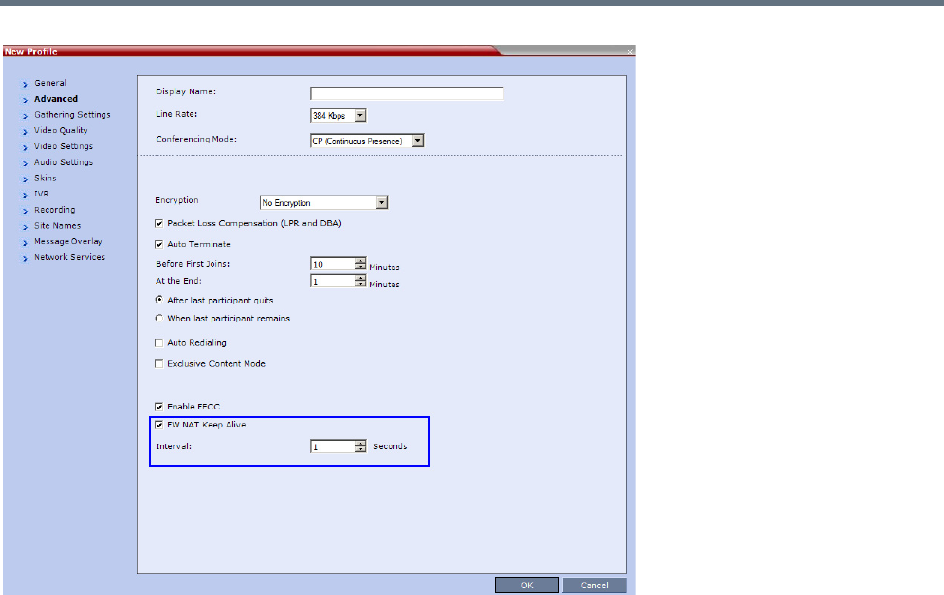
Network Security
Polycom®, Inc. 565
»Select the FW NAT Keep Alive check box and if required, modify the Interval field within the range
of 5 - 86400 seconds.
System Configuration in SBC environments
In an environment that includes SAM (a Polycom SBC), to ensure that a RealPresence Mobile endpoint can
send content to a conference the value of the system flag
NUM_OF_INITIATE_HELLO_MESSAGE_IN_CALL_ESTABLISHMENT must be set to at least 3.
For more details on modifying the values of system flags, see Modifying System Flags.
SIP TCP Keep-Alive
SIP TCP Keep Alive behavior is defined for each IP Network Service and can be modified by adding the
following System Flags and modifying their values:
●SIP_TCP_KEEP_ALIVE_TYPE
●SIP_TCP_KEEP_ALIVE_BEHAVIOR

Polycom®, Inc. 566
IVR Services
Interactive Voice Response (IVR) is an application that allows participants to communicate with the
conferencing system via their endpoint’s input device (such as a remote control). The IVR Service includes
a set of voice prompts and a video slide used to automate the participants connection to a conference or
Entry Queue. It allows customization of menu driven scripts and voice prompts to meet different needs and
languages.
The IVR module includes two types of services:
●Conference IVR Service that is used with conferences
●Entry Queue IVR Service that is used with Entry Queues
The system is shipped with two default Conference IVR Services (one for the conferences and the other for
gateway calls) and one default Entry Queue IVR Service. The default services include voice messages and
video slides in English.
To customize the IVR messages and video slide perform the following operations:
●Record the required voice messages and create a new video slide.
For more information, see Creating a Welcome Video Slide.
●Optional. Add the language to the list of languages supported by the system.
●Upload the voice messages to the MCU (This can be done as part of the language definition or during
the IVR Service definition).
●Create the Conference IVR Service and upload the video slide, and if required any additional voice
messages.
●Optional. Create the Entry Queue IVR Service and upload the required video slide and voice
messages.
IVR Services List
You can view the currently defined Conference IVR and Entry Queue IVR Services in the IVR Services list
pane.
To view the IVR Services list:
1In the Collaboration Server Management pane, expand the Rarely Used list.
When upgrading the Collaboration Server software version new DTMF Codes and voice messages
are not automatically added to existing IVR Services in order to avoid conflicts with existing DTMF
codes. Therefore, to use new options, new Conference and Entry Queue IVR Services must be
created.
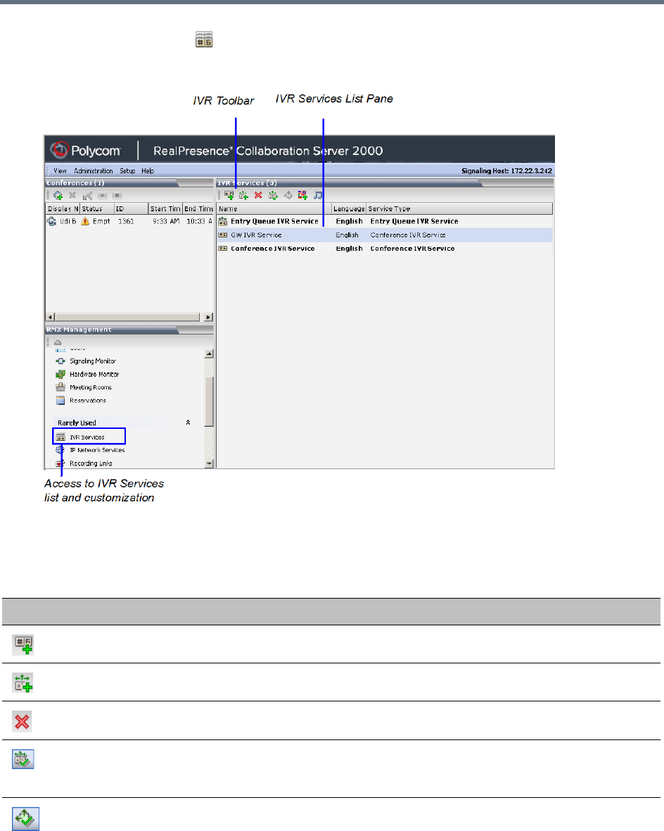
IVR Services
Polycom®, Inc. 567
2Click the IVR Services () entry.
The list pane displays the Conference IVR Services list and the total number of IVR services currently
defined in the system.
IVR Services Toolbar
The IVR Services toolbar provides quick access to the IVR Service definitions as follows:
IVR Toolbar buttons
Button Button Name Descriptions
New Conference IVR Service Creates a new Conference IVR Service.
New Entry Queue IVR Service Creates a new Entry Queue IVR Service.
Delete Service Deletes the selected IVR service(s).
Set Default Conference IVR
Service
Sets the selected Conference IVR Service as default. When
creating a new conference Profile the default IVR Service is
automatically selected for the Profile (but can be modified).
Set Default Entry Queue Service Sets the selected Entry Queue IVR Service as default. When
creating a new Entry Queue the default Entry Queue IVR
Service is automatically selected.
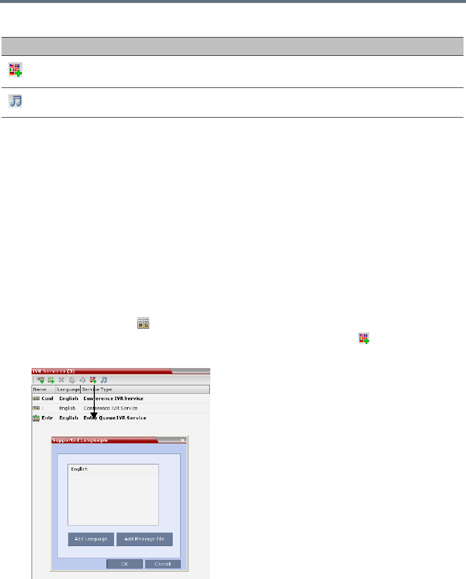
IVR Services
Polycom®, Inc. 568
Adding Languages
You can define different sets of audio prompts in different languages, allowing the participants to hear the
messages in their preferred language.
The Collaboration Server is shipped with a default language (English) and all the prompts and messages
required for the default IVR Services, conference and Entry Queues shipped with the system.
You can add languages to the list of languages for which different messages are downloaded to the MCU
and IVR Services are created. This step is required before the creation of additional IVR messages using
languages that are different from English, or if you want to download additional voice files to existing files in
one operation and not during the IVR service definition.
To add a language:
1In the Collaboration Server Management pane, expand the Rarely Used list.
2Click the IVR Services () entry.
3In the Conference IVR Services list, click the Add Supported Languages ( ) button.
The Supported Languages dialog box opens.
Add Supported
Languages
Adds languages to the IVR module, enabling you to download
voice prompts and messages for various languages.
Replace/Change Music File To replace the currently loaded music file that is used to play
background music, the MCU is shipped with a default music file.
IVR Toolbar buttons
Button Button Name Descriptions
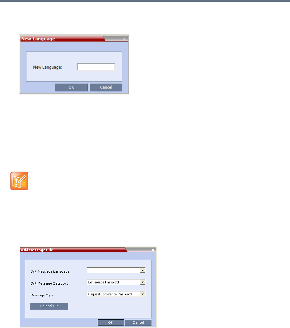
IVR Services
Polycom®, Inc. 569
4Click the Add Language button.
The New Language dialog box opens.
5In the New Language dialog box, enter the name of the new language. The language name can be
typed in Unicode and cannot start with a digit. Maximum field length is 31 characters.
6Click OK.
The new language is added to the list of Supported Languages.
Uploading a Message File to the Collaboration Server
You can upload audio files for the new language or additional files for an existing language now, or you can
do it during the definition of the IVR Service. In the latter case, you can skip the next steps.
To upload messages to the MCU:
1To upload the files to the MCU, in the Supported Languages dialog box, click the Add Message File
button.
The Add Message File dialog box opens.
Audio files are uploaded to the MCU one-by-one.
2In the IVR Message Language list, select the language for which the audio file will be uploaded to
the MCU.
3In the IVR Message Category list, select the category for which the audio file is uploaded.
•Voice messages should not exceed 3 minutes.
•It is not recommended to upload more than 1000 audio files to the MCU memory.

IVR Services
Polycom®, Inc. 570
4In the Message Type list, select the message type for which the uploaded message is to be played.
You can upload several audio files for each Message Type. Each file is downloaded separately.
The table below lists the Message Types for each category:
5Click Upload File to upload the appropriate audio file to the MCU.
The Install File dialog box opens.
IVR Message Types by Message Category
Message
Category Message Type Message
Conference
Password
Request Conference
Password
Requests the participant to enter the conference password.
Request Conference
Password Retry
A participant who enters an incorrect password is requested
to enter it again.
Request Digit Requests the participant to enter any digit in order to connect
to the conference. Used for dial-out participants to avoid
answering machines in the conference.
Welcome
Message
Welcome Message The first message played when the participant connects to
the conference or Entry Queue.
Conference
Chairperson
Request Chairperson
Identifier
Requests the participants to enter the chairperson identifier
key.
Request Chairperson
Password
Requests the participant to enter the chairperson password.
Request Chairperson
Password Retry
When the participant enters an incorrect chairperson
password, requests the participant to enter it again.
General Messages played for system related event notifications, for example, notification that the
conference is locked. Upload the files for the voice messages that are played when an
event occurs during the conference. For more information, see Conference IVR Service
Properties - General Voice Messages.
Billing Code Requests the chairperson to enter the conference Billing Code.
Roll Call Roll call related messages, such as the message played when a participant joins the
conference. Messages are listed in the Conference IVR Service - Roll Call dialog box.
Conference ID Requests the participant to enter the required Conference ID to be routed to the
destination conference.
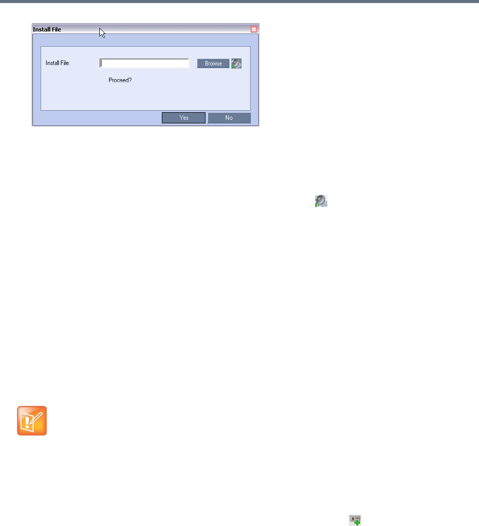
IVR Services
Polycom®, Inc. 571
6Enter the file name or click the Browse button to select the audio file to upload.
The Select Source File dialog box opens.
7Select the appropriate *.wav audio file, and then click the Open button.
The name of the selected file is displayed in the Install field in the Install File dialog box.
8Optional. You can play a .wav file by selecting the Play button ( ).
9Click Yes to upload the file to the MCU.
The system returns to the Add Message File dialog box.
10 Repeat step
6
for each additional audio file to be uploaded to the MCU.
11 Once all the audio files are uploaded to the MCU, close the Add Message File dialog box and
return to the Add Language dialog box.
12 Click OK.
Defining a New Conference IVR Service
The Collaboration Server is shipped with two default Conference IVR Services and all its audio messages
and video slide. You can define new Conference IVR Services or modify the default Conference IVR
Service. For the definition of Conference IVR Service for gateway calls, see Defining the IVR Service for
Gateway Calls.
Defining a New Conference IVR Service
To define a new Conference IVR Service:
1On the IVR Services toolbar, click the New Conference IVR Service () button.
The New Conference IVR Service - Global dialog box opens.
Up to 80 IVR Services (Conference IVR Services and Entry Queue IVR Services) can be defined
per Collaboration Server.
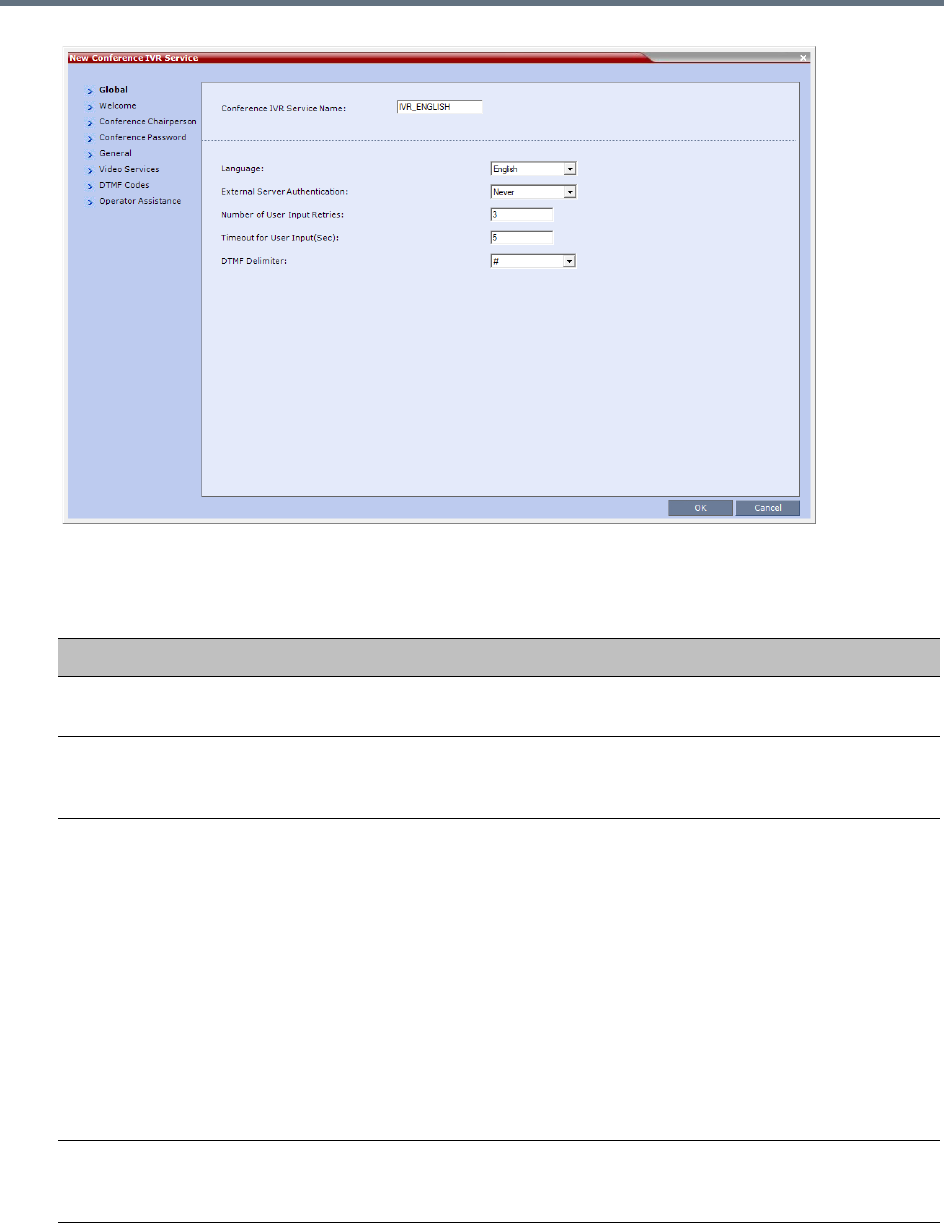
IVR Services
Polycom®, Inc. 572
2Define the following parameters:
Conference IVR Service Properties - Global Parameters
Field/Option Description
Conference IVR Service
Name
Enter the name of the Conference IVR Service. The maximum field length is 20
characters and may be typed in Unicode.
Language For IVR Select the language of the audio messages and prompts from the list of
languages defined in the Supported languages. The default language is
English. For more information, see Adding Languages.
External Server
Authentication
This option is not supported with Collaboration Server 1800.
You can configure the IVR Service to use an external database application to
verify a participant’s right to join the conference. For more information, see
Conference Access with External Database Authentication.
Select one of the following options:
• Never – The participant’s right to join the conference will not be verified with
an external database application (default).
• Always – Any participant request to join the conference is validated with the
external database application using a password.
• Upon Request – Only the participant request to join the conference as
chairperson is validated with the external database application using a
password. The validation process occurs only when the participant enters the
chairperson identifier key.
Number of User Input
Retries
Enter the number of times the participant will be able to respond to each menu
prompt before being disconnected from the conference. Range is between 1-4,
and the default is 3.
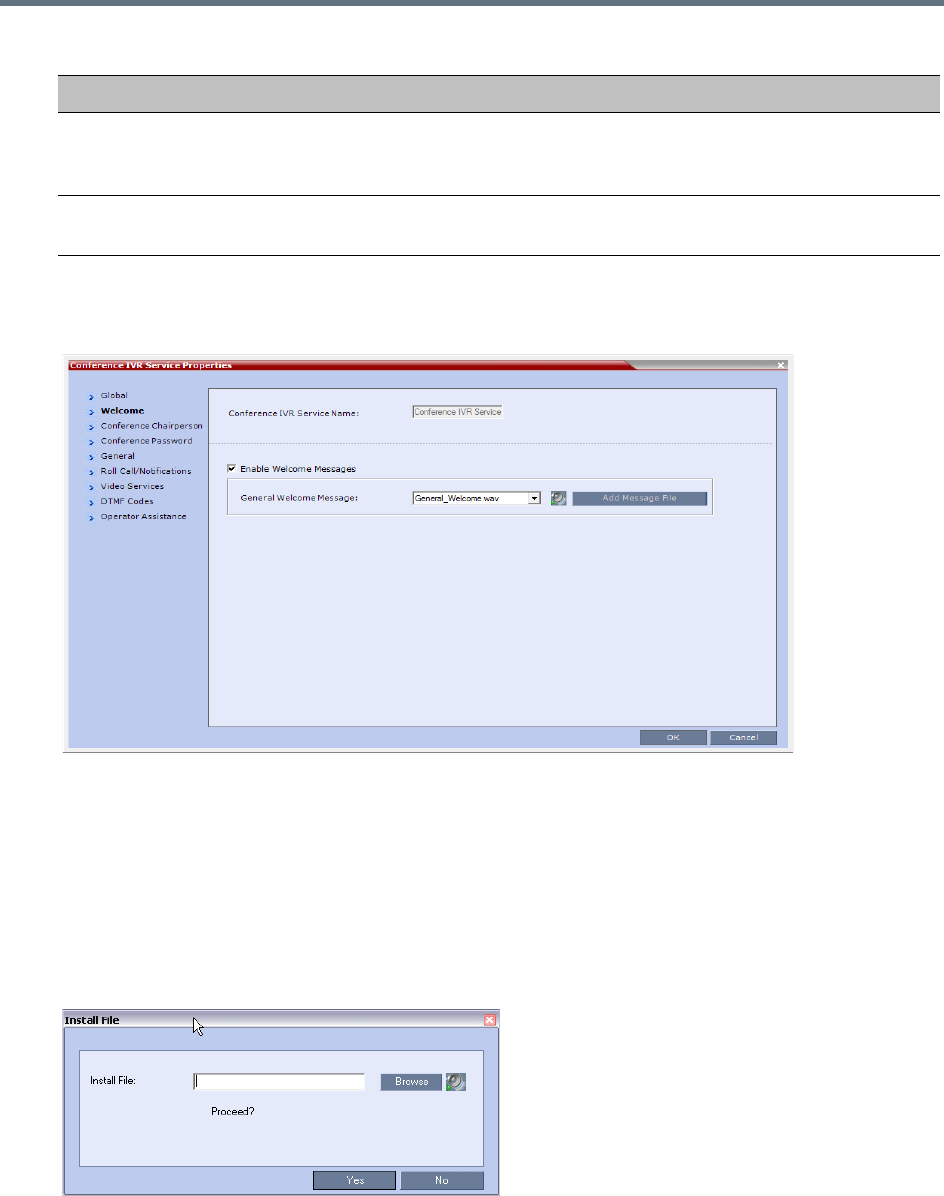
IVR Services
Polycom®, Inc. 573
3Click the Welcome tab.
The New Conference IVR Service - Welcome dialog box opens.
4Select the Enable Welcome Messages check box to define the system behavior when the
participant enters the Conference IVR queue. When participants access a conference through an
Entry Queue, they hear messages included in both the Entry Queue Service and Conference IVR
Service. To avoid playing the Welcome Message twice, disable the Welcome Message in the
Conference IVR Service.
5Select the General Welcome Message, to be played when the participant enters the conference
IVR queue.
6To upload an audio file for an IVR message, click Add Message File.
The Install File dialog box opens.
Timeout for User Input
(Sec)
Enter the duration in seconds that the system will wait for the participant’s input
before prompting for another input. Range is between 1-10, and the default
value is 5 seconds.
DTMF Delimiter Enter the key that indicates the last input key. Possible values are the pound (#)
and star (*) keys. The default is #.
Conference IVR Service Properties - Global Parameters
Field/Option Description
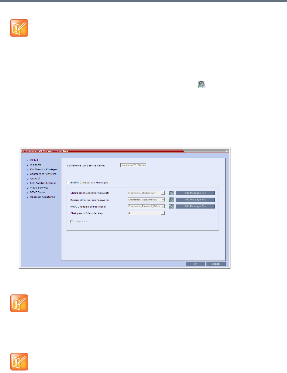
IVR Services
Polycom®, Inc. 574
aClick the Browse button to select the audio file (*.wav) to upload.
The Select Source File dialog box opens.
bSelect the appropriate *.wav audio file and then click the Open button.
cOptional. You can play a .wav file by selecting the Play button ( ).
dIn the Install File dialog box, click Yes to upload the file to the MCU memory.
The Done dialog box opens.
eOnce the upload is complete, click OK and return to the IVR dialog box. The new audio file can
now be selected from the list of audio messages.
7Click the Conference Chairperson tab.
The New Conference IVR Service - Conference Chairperson dialog box opens.
8Select the Enable Chairperson Messages check box to enable the chairperson functionality. If this
feature is disabled, participants are not able to connect as the chairperson.
9Select the various voice messages and options for the chairperson connection.
The Collaboration Server unit is bundled with default audio IVR message files. To upload a
customized audio file, see Creating Audio Prompts and Video Slides.
When both Conference Password and Chairperson Password options are enabled and defined, the
system first plays the prompt Enter conference password. However, if the participant enters
the chairperson password, the participant becomes the chairperson.
To play the prompt requesting the Chairperson password, For conference chairperson
services..., do not select the Enable Password Messages option.
If the files were not uploaded prior to the definition of the IVR Service or if you want to add new audio
files, click Add Message File to upload the appropriate audio file to the Collaboration Server.
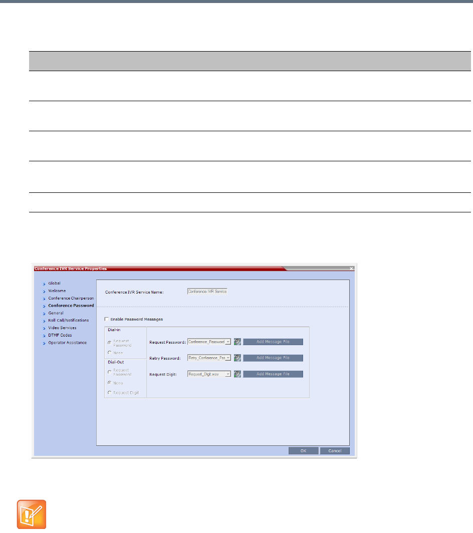
IVR Services
Polycom®, Inc. 575
10 Click the Conference Password tab.
The New Conference IVR Service - Conference Password dialog box opens.
11 Select the Enable Password Messages check box to request the conference password before
moving the participant from the conference IVR queue to the conference.
12 Select the MCU behavior for password request for Dial-in and Dial-out participant connections.
Select the required system behavior as follows:
Request password - The system requests the participant to enter the conference password.
New Conference IVR Service Properties - Conference Chairperson Options and Messages
Field/Option Description
Chairperson Identifier
Request
Select the audio file that requests the participants to enter the key that identifies
them as the conference chairperson.
Request Chairperson
Password
Select the audio file that prompts the participant for the chairperson password.
Retry Chairperson
Password
Select the audio file that prompts participants to re-enter the chairperson
password if they enter it incorrectly.
Chairperson Identifier
Key
Enter the key to be used for identifying the participant as a chairperson.
Possible keys are: pound key (#) or star (*).
Billing Code The prompt requesting the chairperson billing code selected in the General tab.
When both Conference Password and Chairperson Password are enabled and defined, the system
first plays the prompt Enter conference password. However, if the participant enters the
chairperson password, the participant becomes the chairperson.
To play the prompt requesting the Chairperson password, For conference chairperson
services..., do not select the Enable Password Messages option.

IVR Services
Polycom®, Inc. 576
None - The participant is moved to the conference without any password request.
Request Digit - The system requests the participant to enter any key. This option is used mainly
for dial-out participants and to prevent an answering machine from entering the conference.
13 Select the various audio messages that will be played in each case.
14 Click the General tab.
The New Conference IVR Service - General dialog box opens.
The General dialog box lists messages that are played during the conference. These messages are
played when participants or the conference chairperson perform various operations or when a
change occurs.
15 To assign the appropriate audio file to the message type, click the appropriate table entry, in the
Message File column. A drop-down list is enabled.
16 From the list, select the audio file to be assigned to the event/indication.
17 Repeat steps 15 and 16 to select the audio files for the required messages.
The following types of messages and prompts can be enabled:
New Conference IVR Service Properties - Conference Password Parameters
Option Description
Request Password Select the audio file that prompts the participant for the conference password.
Retry Password Select the audio file that requests the participant to enter the conference
password again when failing to enter the correct password.
Request Digit Select the audio file that prompts the participant to press any key when the
Request Digit option is selected.

IVR Services
Polycom®, Inc. 577
Conference IVR Service Properties - General Voice Messages
Message Type Description
Blip on Cascade Link Indicates that the link to the cascaded conference connected successfully.
Chairperson Exit Informs all the conference participants that the chairperson has left the
conference, causing the conference to automatically terminate after a short
interval.
Note: This message is played only when the Requires Chairperson option is
selected in the Conference Profile - IVR dialog box.
Chairperson Help Menu A voice menu is played upon a request from the chairperson, listing the
operations and their respective DTMF codes that can be performed by the
chairperson. The playback can be stopped any time.
Note: If you modify the default DTMF codes used to perform various operations,
the default voice files for the help menus must be replaced.
Change Chairperson
Password
Requests the participant to enter a new chairperson password when the
participant is attempting to modify the chairperson password.
Change Conference
Password
Requests the participant to enter a new conference password when the
participant is attempting to modify the conference password.
Change Password
Failure
A message played when the participant enters an invalid password, for example
when a password is already in use.
Change Passwords
Menu
This voice menu is played when the participants requests to change the
conference password. This message details the steps required to complete the
procedure.
Conference is Locked This message is played to participants attempting to join a Secured conference.
Conference is Secured This message is played when the conference status changes to Secure as
initiated by the conference chairperson or participant (using DTMF code *71).
Conference is unsecured This message is played when the conference status changes to Unsecured as
initiated by the conference chairperson or participant (using DTMF code #71).
Confirm Password
Change
Requests the participant to re-enter the new password.
Dial Tone The tone that will be played to indicate a dialing tone, to let the calling participant
enter the destination number.
Note: This option is not available in SVC conferences and for SVC participants
in mixed CP and SVC conferences.
Disconnect on Busy The Busy Tone is played when the system retries to redial a busy destination
number and fails after exceeding the number of redials. This call is then
disconnected.
Note: This option is not available in SVC conferences and for SVC participants
in mixed CP and SVC conferences.

IVR Services
Polycom®, Inc. 578
Disconnect on No
Answer
The Reorder Tone is played when the system retries to redial a destination
number that does not answer and fails after exceeding the number of redials.
This call is then disconnected.
Note: This option is not available in SVC conferences and for SVC participants
in mixed CP and SVC conferences.
Disconnect on Wrong
Number
A voice message is played when the call fails because of an incorrect
destination number. The message is followed the Reorder Tone and the call is
disconnected.
Note: This option is not available in SVC conferences and for SVC participants
in mixed CP and SVC conferences.
End Time Alert Indicates that the conference is about to end.
Enter Destination ID Prompts the calling participant for the destination number. Default message
prompts the participant for the conference ID (same message as in the Entry
Queue IVR Service).
Note: This option is not available in SVC conferences and for SVC participants
in mixed CP and SVC conferences.
First to Join Informs the participant that he or she is the first person to join the conference.
Incorrect Destination ID If the participant entered an incorrect conference ID (in gateway calls it is the
destination number), requests the participant to enter the number again.
Note: This option is not available in SVC conferences and for SVC participants
in mixed CP and SVC conferences.
Maximum Number of
Participants Exceeded
Indicates the participant cannot join the destination conference as the maximum
allowed number of participants will be exceeded.
Mute All Off This message is played to the conference to inform all participants that they are
unmuted (when Mute All is cancelled).
Mute All On Informs all participants that they are muted, with the exception of the conference
chairperson.
Note: This message is played only when the Mute All Except Me option is
activated.
No Video Resources
Audio Only.
Informs the participant of the lack of Video Resources in the Collaboration
Server and that he/she is being connected as Audio Only.
Participant Help Menu A voice menu that is played upon request from a participant, listing the
operations and their DTMF codes that can be performed by any participant.
Password Changed
Successfully
A message is played when the password was successfully changed.
Recording Failed This message is played when the conference recording initiated by the
chairperson or the participant (depending on the configuration) fails to start.
Recording in Progress This message is played to participant joining a conference that is being recorded
indicating the recording status of the conference.
Conference IVR Service Properties - General Voice Messages
Message Type Description
IVR Services
Polycom®, Inc. 579
18 Click the Roll Call/Notifications tab.
The New Conference IVR Service - Roll Call dialog box opens.
The Roll Call feature of the Conference IVR Service is used to record the participants’ names for
playback when the participants join and leave a conference.
Roll Call announcements played upon a participant’s connection or disconnection from a conference
(Entry and Exit announcements) can be replaced by tones. These tones can be used as notification
when participants join or leave the conference but the identification of the participant is not required.
The system is shipped with two default tones: Entry Tone and Exit tone. When the Tone Notifications
option is enabled, no recording of the participant names will occur and the conference chairperson
will not be able to ask for a name review during the conference.
In Collaboration Server 1500/2000/4000, the selection of tones in the IVR Service definition replaces
the functionality of the system flag IVR_ROLL_CALL_USE_TONES_INSTEAD_OF_VOICE.
19 Select one of the following options to determine the announcement mode:
Redial on Wrong Number A message is played requesting the participant to enter a new destination
number followed by up to five redial attempts. If all redial attempts fail, the
participant is alerted by an IVR message that the dialed number is unreachable,
followed by the Reorder Tone and disconnection.
Note: This option is not available in SVC conferences and for SVC participants
in mixed CP and SVC conferences.
Request Billing Code Requests the participant to enter a code for billing purposes.
Requires Chairperson The message is played when the conference is on hold and the chairperson
joins the conference. For this message to be played the Conference Requires
Chairperson option must be selected in the Conference Profile - IVR dialog
box.
Ringing Tone The tone that will be played to indicate that the system is calling the destination
number.
Note: This option is not available in SVC conferences and for SVC participants
in mixed CP and SVC conferences.
Self Mute A confirmation message that is played when participants request to mute their
line.
Self Unmute A confirmation message that is played when participants request to unmute their
line.
The Roll Call and Tone Notification options are disabled in SVC and mixed CP and SVC
conferences.
Conference IVR Service Properties - General Voice Messages
Message Type Description
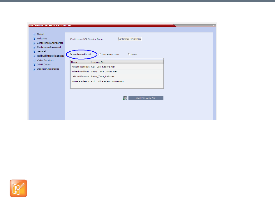
IVR Services
Polycom®, Inc. 580
aTo enable the Roll Call feature, select the Enable Roll Call option.
bSelect Enable Tones to enable the Tone Notifications option.
The dialog box changes to display the tone notification options.
cSelect None to disable the Roll Call and Tone Notifications features.
20 If you enable the Roll Call option, assign the audio file to the message type in the Message File
column, and click the appropriate table entry.
An arrow appears in the Message File column.
21 Click the arrow to open the Message File list and select the appropriate audio file.
If the Roll Call option is enabled, you must assign the appropriate audio files to all message types.
IVR Services
Polycom®, Inc. 581
Once a conference is enabled for Roll Call, Roll Call can be disabled using the #42 or enabled using
the * 42 DTMF Codes. or enabled with all connected participants in the conference receiving the
<name> has joined/left the conference announcement.
For all connected participants in the conference while the Roll Call is disabled (#42)
Joining participants are requested to say their name.
The conference is not interrupted with join/left announcements.
Roll call review is possible.
For all connected participants in the conference while the roll call is enabled (*42)
Joining participant are requested to say their name.
The conference is interrupted with join/left prompts.
Roll call review is possible.
If Roll Call is enabled, when a participant joins or leaves a conference, the system plays a voice
message to all participants. The audio message consists of the joining or leaving participant’s Roll
Call name followed by either “has joined the conference” or “has left the conference”.
These voice messages can be replaced with audio tones. The use of tones requires that the
appropriate tone files in *.wav format be uploaded and configured to replace the Roll Call
Joined.wav and Roll Call Left.wav message files.
22 If you enable the Tone Notifications option, select the Entry Tone or Exit tone.
Conference IVR Service Properties - Roll Call Messages
Roll Call Message Description
Roll Call Record Requests participants to state their name for recording, when they connect to
the conference.
Note: The recording is automatically terminated after two seconds.
Roll Call Joined A voice message stating that the participant has joined the conference.
Note: In Collaboration Server 1500/2000/4000, when the system flag
IVR_ROLL_CALL_USE_TONES_INSTEAD_OF_VOICE is set to YES, the
system does not playback the Roll Call names when participants enter the
conference. However, the voice message will be played, unless it is replaced
with tone file. In such a case, the use of tones requires the uploading of the
appropriate tone files in *.wav format and replacing the Roll Call Joined
message file with the tone file.
Roll Call Left A voice message stating that the participant has left the conference.
Note: In Collaboration Server 1500/2000/4000, when the system flag
IVR_ROLL_CALL_USE_TONES_INSTEAD_OF_VOICE is set to YES, the
system does not playback the Roll Call names when participants exit the
conference. However, the voice message will be played, unless it is replaced
with tone file. In such a case, the use of tones requires the uploading of the
appropriate tone files in *.wav format and replacing the Roll Call Left message
file with the tone file.
Roll Call Review Played when Roll Call is requested by the chairperson, introducing the names of
the conference participants in the order they joined the conference.
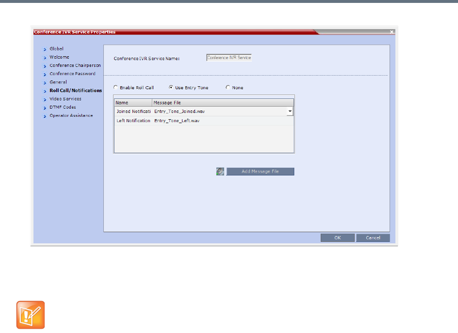
IVR Services
Polycom®, Inc. 582
aClick the appropriate table entry in the Message File column.
A drop-down list is enabled.
bFrom the list, select the audio file to be assigned to the event/indication.
If the Tones option is enabled, you must assign the appropriate audio files to all notification types.
The Collaboration Server system is shipped with two default tones: Entry_tone.wav and
Exit_tone.wav.
If required, you can upload customized audio files that will be played when participants join or leave
the conference.
If the option to play a tone when a cascading link connection is established, make sure that the tone
selected for Entry or Exit notification differ from the cascading link tone as the latter one cannot be
customized.
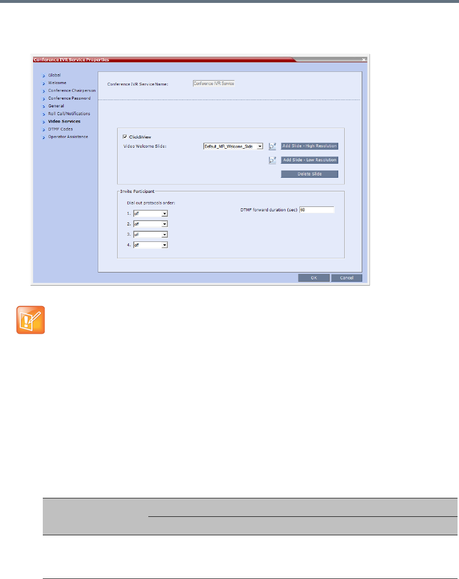
IVR Services
Polycom®, Inc. 583
23 Click the Video Services tab.
The New Conference IVR Service - Video Services dialog box opens.
.
In addition to the low and high resolution slides included in the default slide set, customized low and
high resolution slides are supported.
The following guidelines apply:
Two customized slides can be loaded per IVR Service:
A low resolution slide, to be used with low resolution endpoints.
A high resolution slide, to be used with high resolution endpoints.
The following table summarizes the recommended input slide formats and the resulting slides that
are generated:
The Click&View and Invite Participants features are disabled in SVC and mixed CP and SVC
conferences.
IVR Slide - Input / Output Formats
Slide Resolution
Format
Input Slides Generated Slides
High
HD1080p (16:9)
or
HD720p (16:9)
HD1080p
HD720p

IVR Services
Polycom®, Inc. 584
The source images for the high resolution slides must be in *.bmp or *.jpg format.
If the uploaded slides are not of the exact SD or HD resolution, an error message is displayed and
the slides are automatically cropped or enlarged to the right size.
If a slide that is selected in an IVR Service is deleted, a warning is displayed listing the IVR
Services in which it is selected. If deleted, it will be replaced with a default Collaboration Server
slide.
The generated slides are not deleted if the system is downgraded to a lower software version.
The first custom source file uploaded, whatever its format, is used to generate both high and low
resolution custom slides. High resolution source files uploaded after the first upload will be used
to generate and replace high resolution custom slides. Likewise, low resolution source files
uploaded after the first upload will be used to generate and replace low resolution custom slides.
If there are two custom source files in the folder, one high resolution, one low resolution, and a
new high resolution custom source file is uploaded, new high resolution custom slides are
created. The existing low resolution custom slides are not deleted.
If there are two custom source files in the folder, one high resolution, one low resolution, and a
new low resolution custom source file is uploaded, new low resolution custom slides are created.
The existing high resolution custom slides are not deleted.
24 Define the following parameters
:
Low
4CIF (4:3)
or
CIF (4:3)
4SIF
SIF
CIF
New Conference IVR Service Properties - Video Services Parameters
Video
Services Description
Click&View Select this option to enable endpoints to run the Click&View application that enables
participants to select a video layout from their endpoint.
Note: This option is not available in SVC conferences and for SVC participants in mixed CP
and SVC conferences.
Video
Welcome
Slide
Select the Low Resolution and High Resolution video slides to be displayed when
participants connect to the conference.
To view any slide, click the Preview Slide () button.
Notes:
•When using one of the default Polycom slides, the slide will be displayed in the resolution
defined in the profile, i.e. CIF, SD, HD 720p or HD 1080p. When defining a gateway IVR
Service, the recommended default slide is: Default_GW_Welcome_Slide.
•Customized H.261 slides are not supported.
When Collaboration Server is configured to IPv6, the IVR slide is displayed without taking
into account the MTU Size.
IVR Slide - Input / Output Formats
Slide Resolution
Format
Input Slides Generated Slides
IVR Services
Polycom®, Inc. 585
25 If the video slide file was not uploaded to the MCU prior to the IVR Service definition, click the:
Add Slide - Low Resolution button to upload a Low Resolution Slide.
Add Slide - High Resolution button to upload a High Resolution Slide.
The Install File dialog box opens. The uploading process is similar to the uploading of audio files.
For more information, see step 6 above.
Invite
Participant
See Inviting Participants using DTMF.
Note: The Invite Participant feature is not available in SVC conferences and for SVC
participants in mixed CP and SVC conferences.
Dial out
protocols
order
Select the order of the network protocols that will be used by the system to dial the
destination number. The system will start dialing using the first protocol, and if the call is not
answered it will continue with the second, third and fourth protocols (if they are enabled)
until the call is answered. By default, H.323 is set as the first protocol and SIP as the second
while the remaining protocols are disabled (set to Off).
For PSTN calls, select the PSTN protocol and not ISDN.
Set PSTN before ISDN if both PSTN and ISDN protocols are required.
DTMF
forward
duration
Use this field when connecting to another conferencing entity with an IVR, requiring the
input of a password, destination number or ID. Enter the number of seconds that the system
will wait for the input of an additional DTMF digits such as a password or conference
number.
Range: 10 - 600 seconds
Default: 60 seconds.
•The video slide must be in a .jpg or .bmp file format. For more information, see Creating a
Welcome Video Slide.
•Customized H.261 slides are not supported.
New Conference IVR Service Properties - Video Services Parameters
Video
Services Description
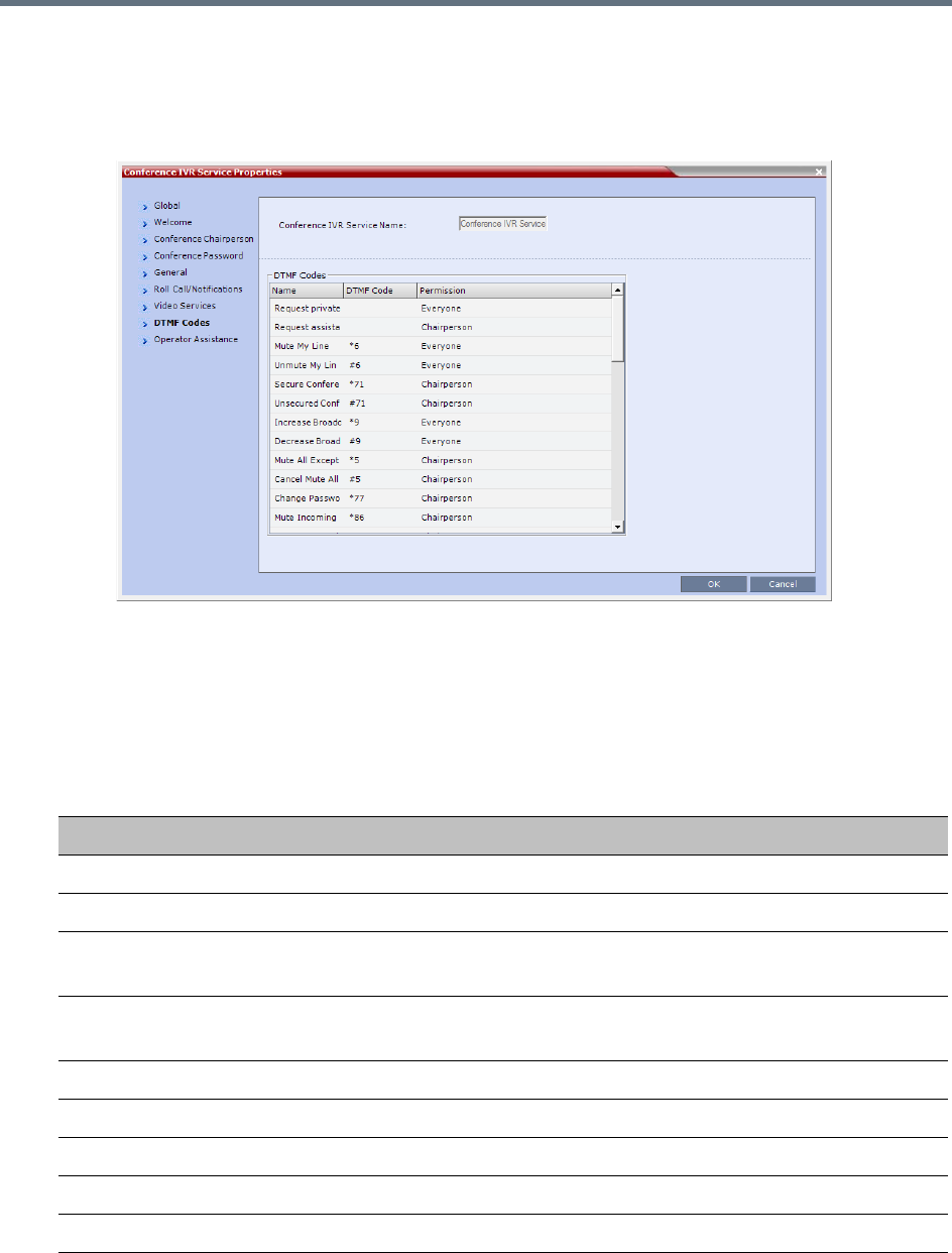
IVR Services
Polycom®, Inc. 586
26 Click the DTMF Codes tab.
The New Conference IVR Service - DTMF Codes dialog box opens.
This dialog box lists the default DTMF codes for the various functions that can be performed during
the conference by all participants or by the chairperson.
Participants and chairpersons can manage their connection to ongoing conferences from their
endpoints, using DTMF codes from their endpoints. Chairpersons can also control an ongoing
conference using DTMF codes.
To use the DTMF codes to control the conference, the DTMF input must be first enabled on the
endpoint remote control.
New Conference IVR Service Properties - DTMF Codes
Operation DTMF String Permission
Mute My Line *6 Everyone
Unmute My Line #6 Everyone
Increase Broadcast Volume
Note: This option is not available for SVC participants.
*9 Everyone
Decrease Broadcast Volume
Note: This option is not available for SVC participants.
#9 Everyone
Mute All Except Me *5 Chairperson
Cancel Mute All Except Me #5 Chairperson
Change Password *77 Chairperson
Mute Incoming Participants *86 Chairperson
Unmute Incoming Participants #86 Chairperson

IVR Services
Polycom®, Inc. 587
Play Help Menu *83 Everyone
Enable Roll Call
Note: This option is not available in SVC conferences.
*42 Chairperson
Disable Roll Call
Note: This option is not available in SVC conferences.
#42 Chairperson
Roll Call Review Names
Note: This option is not available in SVC conferences.
*43 Chairperson
Roll Call Stop Review Names
Note: This option is not available in SVC conferences.
#43 Chairperson
Terminate Conference *87 Chairperson
Start Click&View
Note: This option is not available for SVC participants.
** Everyone
Start PCM
Note: This option is not available for SVC participants.
## Chairperson
Invite Participant
Note: This option is not available for SVC participants.
*72 Everyone
Disconnect Last Invited Participant
Note: This option is not available for SVC participants.
#72 Chairperson
Change To Chairperson *78 Everyone
Increase Listening Volume
Note: This option is not available for SVC participants.
*76 Everyone
Decrease Listening Volume
Note: This option is not available for SVC participants.
#76 Everyone
Override Mute All Configurable Everyone
Start Recording *2 Chairperson
Stop Recording *3 Chairperson
Pause Recording *1 Chairperson
Secure Conference *71 Chairperson
Unsecured Conference #71 Chairperson
Show Number of Participants
Note: This option is not available in SVC conferences.
*88 Everyone
Request individual assistance
Note: This option is not available for SVC participants.
*0 Everyone
New Conference IVR Service Properties - DTMF Codes
Operation DTMF String Permission
IVR Services
Polycom®, Inc. 588
27 To modify the DTMF code or permission:
aIn the DTMF Code column, in the appropriate entry enter the new code.
bIn the Permission column, select from the list who can use this feature (Everyone or just the
Chairperson).
Request assistance for conference
Note: This option is not available for SVC participants.
00 Chairperson
Request to Speak 99 Everyone
Touch Control Prefix
Note: This option is not available for SVC participants.
*# Everyone
Do not change the DTMF code of the Touch Control Prefix (*#).
The Polycom® Touch Control device is only supported with MPM+ and MPMx media cards. For
more information see the Polycom® Touch Control User Guide.
If during the ongoing conference the Show Number of Participants DTMF option (default DTMF
*88) is used, when the displayed number of participants is removed, the message overlay text is also
removed.
By default, the Secure, Unsecure Conference and Show Number of Participants options are enabled
in the Conference IVR Service.When Secured Conference is enabled, it locks the conference
and prevents participants and Collaboration Server Users from joining the conference. A
Secured Conference cannot be monitored or controlled. In the Secured Conference mode,
the Administrator cannot view the participant or conference properties, but can manually
terminate them. In the Secured Conference mode, the chairperson and participants can
perform various operations, such as muting through DTMF codes. However, because
Secure conferences cannot be monitored, these operations or status changes are not
displayed in the Conferences or Participants panes.
The Secure, Unsecure Conference and Show Number of Participants options can be disabled by
removing their codes from the Conference IVR Service.
To disable the Text Indication option in the DTMF Code column, clear the DTMF code (*88) of Show
Number of Participants from the table.
To disable the Secure Conference options, in the DTMF Code column, clear the DTMF codes of
both Secured Conference (*71) and Unsecured Conference (#71) from the table.
New Conference IVR Service Properties - DTMF Codes
Operation DTMF String Permission
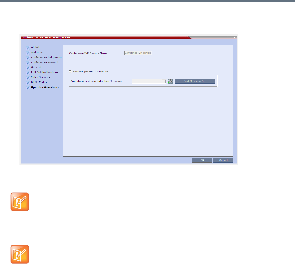
IVR Services
Polycom®, Inc. 589
28 Click the Operator Assistance tab.
The Operator Assistance dialog box opens.
29 Select Enable Operator Assistance to enable operator assistance when the participant requires or
requests help during the connection process to the conference or during the conference.
30 In the Operator Assistance Indication Message field, select the audio message to be played
when the participant requests or is waiting for the operator’s assistance.
31 Click OK to complete the IVR Service definition.
The new Conference IVR Service is added to the IVR Services list.
Change to Chairperson
Regular participants can request to become the conference chairperson using the appropriate DTMF code
(default: *78), which enabled them to perform operations designated for chairpersons only.
The Change to Chairperson via the DTMF code (default: *78) is executed only if the following settings were
configured for the MCU and the conference:
●In the Conference IVR Service - Conference Chairperson dialog box, select the Enable
Chairperson Messages check box, and select the appropriate voice messages.
For more information, see New Conference IVR Service Properties - Conference Chairperson
Options and Messages.
The Operator Assistance option is disabled in SVC conferences.
If the audio file was not uploaded prior to the definition of the IVR Service or if you want to add new
audio files, click Add Message File to upload the appropriate audio file to the Collaboration Server.

IVR Services
Polycom®, Inc. 590
●When starting a new conference or defining a new Meeting Room, define the Chairperson
Password in the conference General dialog box.
For more information, see Creating a New Meeting Room.
Controlling the receipt of in-band and out-of-band DTMF Codes
The RFC2833_DTMF System Flag controls the receipt of in-band or out-of-band DTMF Codes.
When set to YES (default), the RMX will receive DTMF Codes sent in-band. When set to NO the RMX
receives DTMF Codes sent out-of-band. The RMX always sends DTMF Codes in-band (as part of the Audio
Media stream). If you wish to modify the flag value, the flag must be added to the System Configuration file.
For more information see Modifying System Flags.
Entry Queue IVR Service
An Entry Queue (EQ) is a routing lobby for conferences. Participants are routed to the appropriate
conference according to the conference ID they enter.
An Entry Queue IVR Service must be assigned to the Entry Queue to enable the voice prompts and video
slide guiding the participants through the connection process.
An Entry Queue IVR Service is a subset of an IVR Service. You can create different Entry Queue Services
for different languages and personalized voice messages.
The Collaboration Server is shipped with a default Entry Queue IVR Service and all its audio messages and
video slide. You can define new Entry Queue IVR Services or modify the default Entry Queue IVR Service.
Defining a New Entry Queue IVR Service
To set up a new Entry Queue IVR Service:
1In the RMX Management pane, click IVR Services ().
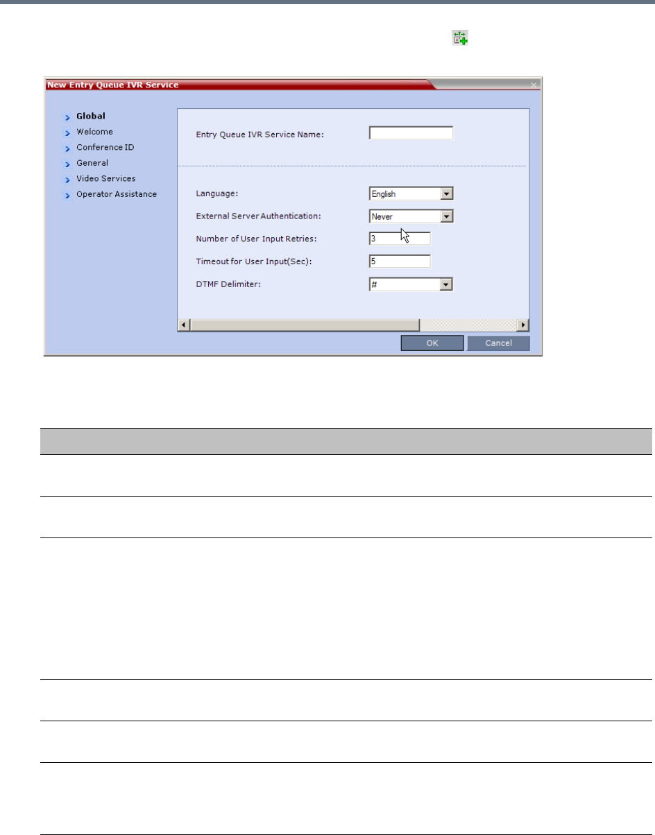
IVR Services
Polycom®, Inc. 591
2In the IVR Services list, click the New Entry Queue IVR Service ( ) button.
The New Entry Queue IVR Service - Global dialog box opens.
3Fill in the following parameters:
Entry Queue IVR Service Properties - Global Parameters
Option Description
Entry Queue Service
Name
(Mandatory) Enter the name of the Entry Queue Service. The name can be
typed in Unicode. Maximum field length is 80 ASCII characters.
Language Select the language in which the Audio Messages and prompts will be heard.
The languages are defined in the Supported Languages function.
External Server
Authentication
This option is used for Ad Hoc conferencing, to verify the participant’s
permission to initiate a new conference. For a detailed description see Appendix
D - Ad Hoc Conferencing and External Database Authentication.
Select one of the following options:
•None to start a new conference without verifying with an external database
the user right to start it.
• Conference ID to verify the user’s right to start a new conference with an
external database application using the conference ID.
Number of User Input
Retries
Enter the number of times the participant is able to respond to each menu
prompt before the participant is disconnected from the MCU.
Timeout for User Input
(Sec.)
Enter the duration in seconds that the system waits for input from the participant
before it is considered as an input error.
DTMF Delimiter The interaction between the caller and the system is done via touch-tone
signals (DTMF codes). Enter the key that will be used to indicate a DTMF
command sent by the participant or the conference chairperson. Possible keys
are the pound key (#) or star (*).
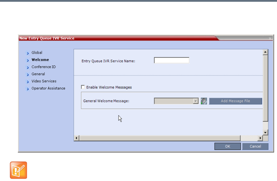
IVR Services
Polycom®, Inc. 592
4Click the Welcome tab.
The New Entry Queue IVR Service - Welcome dialog box opens.
5Define the appropriate parameters. This dialog box contains options that are identical to those in the
Conference IVR Service - Welcome Message dialog box. For more information about these
parameters, see New Conference IVR Service Properties - Conference Chairperson Options and
Messages.
If the files were not uploaded prior to the definition of the IVR Service or if you want to add new audio
files, click Add Message File to upload the appropriate audio file to the Collaboration Server.
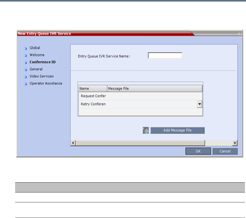
IVR Services
Polycom®, Inc. 593
6Click the Conference ID tab.
The New Entry Queue IVR Service - Conference ID dialog box opens.
7Select the voice messages:
8Assign an audio file to each message type, as follows:
In the Message File column, click the table entry, and then select the appropriate audio message.
Entry Queue IVR Service Properties - Conference ID
Field/Option Description
Request Conference ID Prompts the participant for the conference ID.
Retry Conference ID When the participant entered an incorrect conference ID, requests the
participant to enter the ID again.
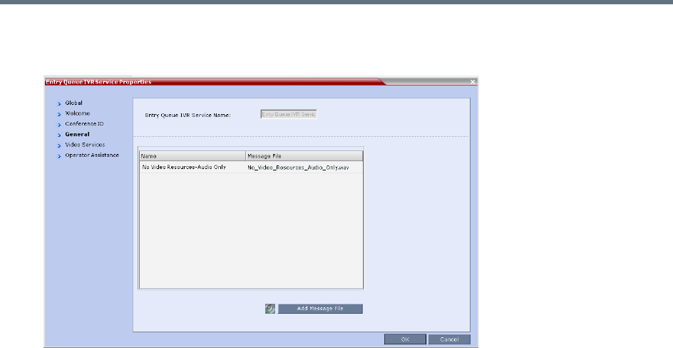
IVR Services
Polycom®, Inc. 594
9Click the General tab.
The New Entry Queue IVR Service - General dialog box opens.
The administrator can enable an audio message that informs the participant of the lack of Video
Resources in the Collaboration Server and that he/she is being connected as Audio Only. The
message states: All video resources are currently in use. Connecting using audio only.
The following guidelines apply:
The IVR message applies to video participants only. Audio Only participants will not receive the
message.
Only H.323 and SIP participants receive the audio message.
Downgrade to Audio Only is not supported for undefined ISDN dial in participants. These
participants are disconnected if there is a lack of Video Resources.
The audio message is the first message after the call is connected, preceding all other IVR
messages.
The message is called No Video Resources-Audio Only and the message file (.wav) is called
No video resources audio only.wav.
The audio message must be added to the Conference and Entry Queue IVR Services
separately.
The IVR message can be enabled/disabled by the administrator using the
ENABLE_NO_VIDEO_RESOURCES_ AUDIO_ONLY_MESSAGE System Flag in system.cfg.
Possible values: YES / NO, default: YES
If you wish to modify the flag value, the flag must be added to the System Configuration file. For
more information see the Modifying System Flags.
10 Enter the message Name and Message File name for the Audio Only message:
Message Name: No Video Resources-Audio Only
Message File name: No_Video_Resources_Audio_Only.wav
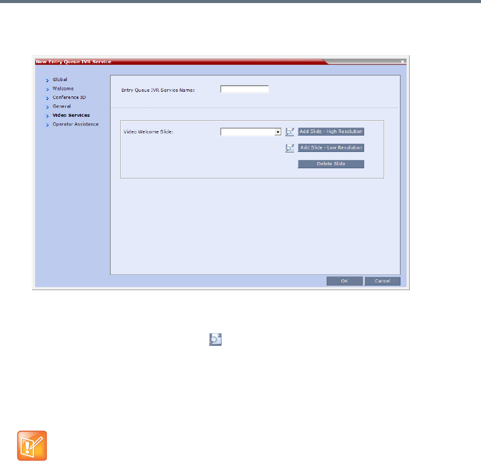
IVR Services
Polycom®, Inc. 595
11 Click the Video Services tab.
The New Entry Queue IVR Service - Video Services dialog box opens.
12 In the Video Welcome Slide list, select the video slide that will be displayed to participants
connecting to the Entry Queue. The slide list includes the video slides that were previously uploaded
to the MCU memory.
13 To view any slide, click Preview Slide ().
14 If the video slide file was not uploaded to the MCU prior to the IVR Service definition, click the:
Add Slide - Low Resolution button to upload a Low Resolution Slide.
Add Slide - High Resolution button to upload a High Resolution Slide.
The Install File dialog box opens. The uploading process is similar to the uploading of audio files.
For more information, see step
6
.
The video slide must be in a .jpg or .bmp file format. For more information, see Creating a Welcome
Video Slide.
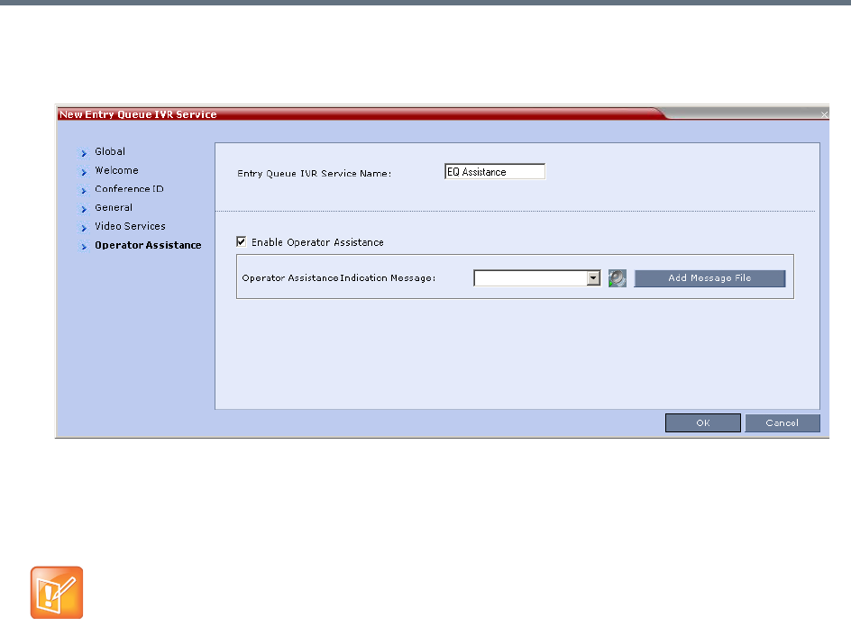
IVR Services
Polycom®, Inc. 596
15 Click the Operator Assistance tab.
The Operator Assistance dialog box opens.
16 Select Enable Operator Assistance to enable operator assistance when the participant requires or
requests help during the connection process.
17 In the Operator Assistance Indication Message field, select the audio message to be played
when the participant requests or is waiting for operator’s assistance.
18 Click OK to complete the Entry Queue Service definition.
19 The new Entry Queue IVR Service is added to the IVR Services list. For more information, see IVR
Services List.
Setting a Conference IVR Service or Entry Queue IVR Service as the
Default Service
The first Conference IVR Service and Entry Queue IVR Service are automatically selected by default. The
IVR Services (Conference and Entry Queue) shipped with the system are also set as default. If additional
Conference IVR Services and Entry Queue IVR Services are defined, you can set another service as the
default for each service type.
If the audio file was not uploaded prior to the definition of the IVR Service or if you want to add new
audio files, click Add Message File to upload the appropriate audio file to the Collaboration Server.
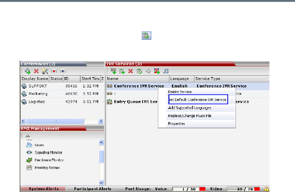
IVR Services
Polycom®, Inc. 597
To select the default Conference IVR Service:
●In the IVR Services list, select the Conference IVR Service to be defined as the default, and then
click Set Default Conference IVR Service ().
Alternatively, in the IVR Services list, right-click the Conference IVR Service and then select Set
Default Conference IVR Service.
The IVR Service is displayed in bold, indicating that it is the current default service.
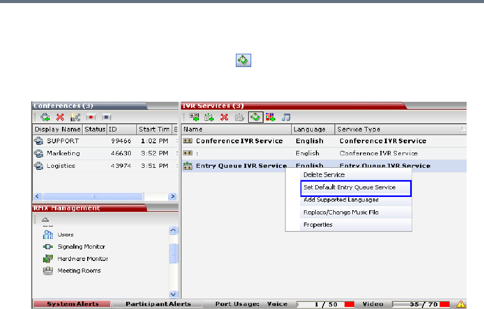
IVR Services
Polycom®, Inc. 598
To select the Default Entry Queue IVR Service:
»In the IVR Services list, select the Entry Queue IVR Service to be defined as the default, and then
click Set Default Entry Queue IVR Service ().
Alternatively, in the Conference IVR Services list, right-click the Entry Queue IVR Service and then
select Set Default Entry Queue IVR Service.
The default Entry Queue IVR Service is displayed in bold, indicating that it is the current default
service.
Modifying the Conference or Entry Queue IVR Service
Properties
You can modify the properties of an existing IVR Service, except the service name and language.
To modify the properties of an IVR Service:
1In the RMX Management pane, click IVR Services.
2In the IVR Services list, Click the IVR Service to modify.
For more information about the tabs and options of this dialog box, see Defining a New Conference
IVR Service.
3Modify the required parameters or upload the required audio files.
4Click OK.
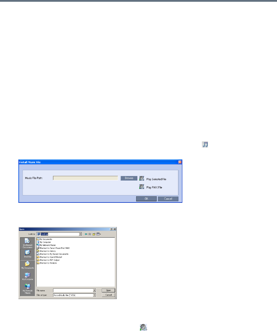
IVR Services
Polycom®, Inc. 599
Replacing the Music File
The Collaboration Server is shipped with a default music file that is played when participants are placed on
hold, for example, while waiting for the chairperson to connect to the conference (if the conference requires
a chairperson), or when a single participant is connected to the conference. You can replace the default
music file with your own recorded music.
Music file guidelines:
●The file must be in *.wav format.
●Music length cannot exceed one hour.
●The music recording must be in the range of (-12dB) to (-9dB).
Adding a Music File
To replace the Music file:
1In the RMX Management pane, click IVR Services.
2In the IVR Services list toolbar, click the Replace/Change Music File ( ) button.
The Install Music File window opens.
3Click the Browse button to select the audio file (*.wav) to upload.
The Open dialog box opens.
4Select the appropriate audio *.wav file and then click Open.
The selected file name is displayed in the Install Music File dialog box.
5You can play the selected file by clicking Play ().
aClick Play Selected File to play a file on your computer.
bClick Play RMX File to play a file already uploaded on the RMX.
6In the Install Music File dialog box, click OK to upload the file to the MCU.
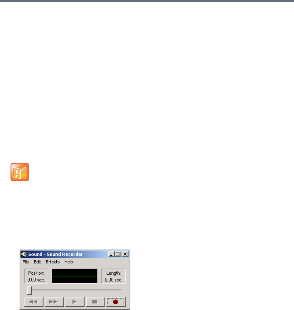
IVR Services
Polycom®, Inc. 600
7The new file replaces the previously uploaded file and this file is used for all background music
played by the MCU.
Creating Audio Prompts and Video Slides
The Collaboration Server is shipped with default voice messages (in WAV format) and video slides that are
used for the default IVR services. You can create your own video slides and record the voice messages for
different languages or customize them to your needs.
Recording an Audio Message
To record audio messages, use any sound recording utility available in your computer or record them
professionally in a recording studio. Make sure that recorded message can be saved as a Wave file (*.wav
format) and that the recorded format settings are as defined in steps 4 and 5 on the following procedure.
The files are converted into the Collaboration Server internal format during the upload process.
This section describes the use of the Sound Recorder utility delivered with Windows 95/98/2000/XP.
Defining the format settings for audio messages
To define the format settings for audio messages:
1On your PC, select Start > Programs > Accessories > Entertainment > Sound Recorder.
The Sound–Sound Recorder dialog box opens.
2To define the recording format, click File > Properties.
The Properties for Sound dialog box opens.
•The format settings for audio messages need to be set only once. The settings will then be applied
to any new audio messages recorded.
•The utility or facility used to record audio messages must be capable of producing audio files with
the formats and attributes as shown in the following procedure, namely, PCM, 16.000kHz, 16Bit,
Mono.
Windows® XP® Sound Recorder is one of the utilities that can be used.
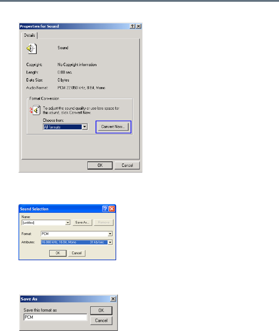
IVR Services
Polycom®, Inc. 601
3Click Convert Now.
The Sound Selection dialog box opens.
4In the Format field, select PCM.
5In the Attributes list, select 16.000 kHz, 16Bit, Mono.
6To save this format, click the Save As button.
The Save As dialog box opens.
7Select the location where the format will reside, enter a name and then click OK.
The system returns to the Sound Selection dialog box.
8Click OK.
The system returns to the Properties for Sound dialog box.
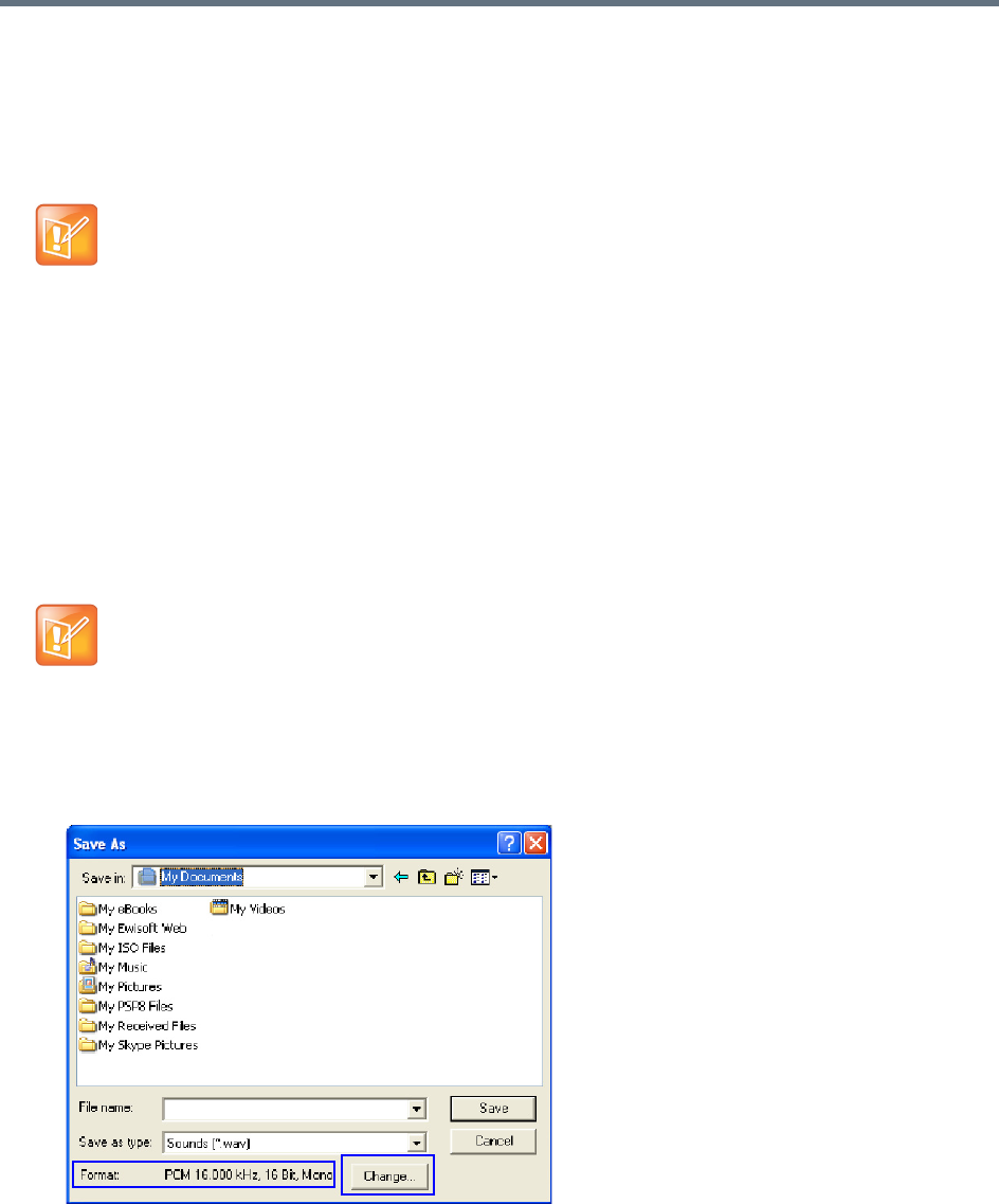
IVR Services
Polycom®, Inc. 602
9Click OK.
The system returns to the Sound–Sound Recorder dialog box. You are now ready to record your
voice message.
Recording a new audio message
To record a new audio message:
Make sure that a microphone or a sound input device is connected to your PC.
1On your PC, click Start > Programs > Accessories > Entertainment > Sound Recorder.
The Sound–Sound Recorder dialog box opens.
2Click File > New.
3Click the Record button.
The system starts recording.
4Start narrating the desired message.
5Click the Stop Recording button.
6Save the recorded message as a wave file, click File > Save As.
The Save As dialog box opens.
Regardless of the recording utility you are using, verify that any new audio message
recorded adheres to the following format settings: 16.000kHz, 16Bit, Mono.
For all audio IVR messages, stop the recording anytime up to 3 minutes (which is the maximum
duration allowed for an IVR voice message). If the message exceeds 3 minutes it will be rejected by
the Collaboration Server unit.
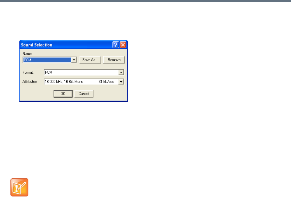
IVR Services
Polycom®, Inc. 603
7Verify that the Format reads: PCM 16.000 kHz, 16Bit, Mono. If the format is correct, continue with
step 10. If the format is incorrect, click Change.
The Sound Selection dialog box is displayed.
8In the Name field, select the name of the format created in step
7
.
9Click OK.
The system returns to the Save As dialog box.
10 In the Save in field, select the directory where the file will be stored.
11 In the Save as Type field, select the *.wav file format.
12 In the File name box, type a name for the message file, and then click the Save button.
13 To record additional messages, repeat steps 1 to 10.
To upload your recorded *.wav file to the Collaboration Server, see step
6
.

IVR Services
Polycom®, Inc. 604
Creating a Welcome Video Slide
The video slide is a still picture that can be created in any graphic application.
To create a welcome video slide:
1Using any graphic application, save your image in either *.jpg or *.bmp file format.
2For optimum quality, ensure that the image dimensions adhere to the Collaboration Server
recommended values (width x height in pixels):
640 x 480
704 x 480
848 x 480
720 x 576
704 x 576
1024 x 576
960 x 720
1280 x 720
1440 x 1088
1920 x 1088
The Collaboration Server can accommodate small deviations from the recommended slide
resolutions.
3Save your file.
Customized H.261 slides are not supported..
If using a default Polycom slide, the slide’s resolution will be as defined in the profile, i.e. SD, HD or
CIF.
If the display of the Welcome slide is cut in the upper area of the screen, change the settings of the
endpoint’s monitor to People Stretch instead of Zoom.
To upload your video slide to the Collaboration Server, see step
12
in Defining a New Entry Queue
IVR Service.

IVR Services
Polycom®, Inc. 605
Inviting Participants using DTMF
A participant in a video or audio conference can invite another participant to the conference using the
touch-tone DTMF numeric keypad on the participant’s endpoint. You can invite a participant using various
communication devices, such as a mobile phone, an IP phone, PSTN phones, laptops, or connect to
another conference running on another PBX or MCU.
Invite Call Flow
The following flow describes how a participant is invited to the conference using the DTMF codes:
1During the conference, the participant enters the DTMF code (default is *72) on the numeric keypad
to invite another participant.
2The participant is prompted to enter the invited participant’s destination number (a number or IP
address) including the prefix (if required) and the DTMF delimiter digit (‘*’ or ‘#’) at the end. The
asterisk (‘*’) is used to denote the dot in the IP address.
For example: To enter an IP address such as 10.245.22.19, on the DTMF keypad press
10*245*22*19 and then the DTMF delimiter.
3The system automatically dials to the destination according to the protocol order as defined in the
IVR Services Properties - Video Services tab.
When the call cannot be completed by the current protocol, the system attempts to connect to the
destination using the next protocol according to the protocol order.
The Collaboration Server connects the participant when the call is answered.
4The last invited participant can be disconnected when the inviting participant enters the DTMF code
(default is #72) on the numeric keypad.
Entering Additional DTMF Codes
In some environments, the call is answered by an IVR system (for example when connecting to another
conference or PBX), requesting a password or a destination number to complete the connection process.
In such a case, additional DTMF digits must be entered before the DTMF forward duration time has
expired and are forwarded to the invited destination. When the additional DTMF codes are entered, they
are heard by all the conference participants.
If the DTMF code is not entered on time or if the wrong DTMF code is entered, the participant is prompted
for a new input. After the defined number of retries have elapsed, the call is ended.
Error Handling
●If the destination endpoint is busy or the participant did not answer, the system ends the call.
This feature is disabled in SVC conferences and for SVC participants in mixed CP and SVC
conferences.
Digits that are entered after the DTMF delimiter and before the participant is connected are ignored.

IVR Services
Polycom®, Inc. 606
●When an incorrect number is entered, the call fails and an error message is displayed.
●If the destination number is not entered in a specific amount of time (defined in Timeout for user
input in the IVR Services - Global tab), the participant is prompted to enter a destination number
again. Depending on the Number of user input retries as defined in the IVR Services - Global tab,
the system will attempt to receive the required input. When all the retries have failed, the call to the
invited participant is cancelled.
Guidelines
●Inviting other participants is available to AVC-enabled participants only.
●Participants can be invited to Event Mode, and CP and VSW conferences.
Event Mode conferencing is not supported on Collaboration Server (RMX) 1800-0.
●All network protocols are supported (H.323, SIP, ISDN, and PSTN). It is recommended to select
PSTN and not ISDN if PSTN is the only destination protocol. If both PSTN and ISDN are enabled, it
is recommended to select the PSTN before ISDN as the connection process for PSTN endpoints will
be quicker.
●In an Multiple IP Networks environment, the system will try to connect the participant using each of
the IP Network Services listed in the Conference Profile - Network Services dialog box. Network
services that are excluded from this list are skipped during the dialing sequence.
●In Event Mode conferences, the invited participant connection parameters must match one of the
conference levels.
●In CP conferences, the participant initiating the invitation to another participant is able to view the
dialing information and connection status. During the dialing process, the dialing string is displayed
as the participant name which is replaced by the site name when connected to the conference.
●By default, all participants (Everyone) are granted permission to invite a participant to join a
conference. To change the permission to the Chairperson, modify the Permission column in the IVR
Service - DTMF Codes tab.
Enabling the Invite Participants using DTMF Option
The option to invite participants to a conference using the DTMF keypad is enabled in the following
Conference IVR Services dialog boxes:
●General
●Video Services
●DTMF Codes
To enable the Invite Participant using DTMF on the Collaboration Server:
1Open an existing or define a new Conference IVR Service.
Conference IVR Service - Global dialog box opens.
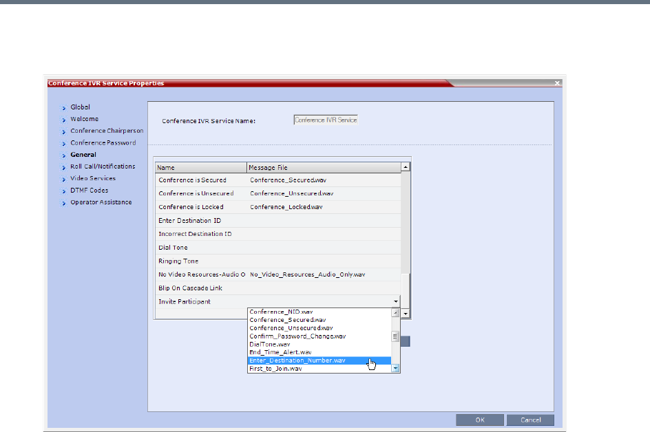
IVR Services
Polycom®, Inc. 607
2Click the General tab.
The Conference IVR Services - General tab is displayed.
3In the Message File column of the Invite Participant entry, click the drop-down arrow and select the
required voice message. The file Enter_Destination_Number.wav that is shipped with the system
can be used for this message.
To upload a new file, click the Add Message File. For more details, see Creating Audio Prompts and
Video Slides.
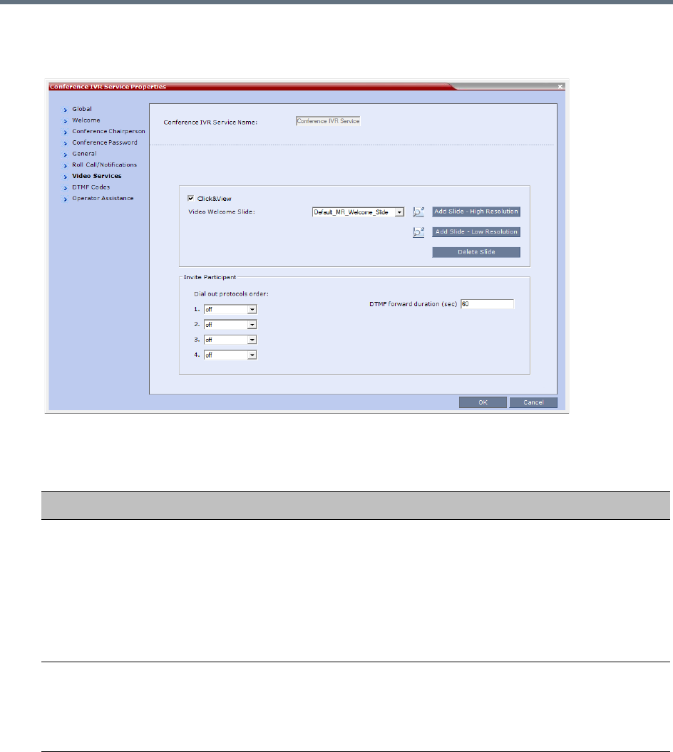
IVR Services
Polycom®, Inc. 608
4Click the Video Services tab.
The IVR Services - Video Services tab is displayed.
5Define the following parameters:
IVR Services Properties - Video Services Parameters - Invite Participants
Video Services Description
Dial out protocols order Select the order of the network protocols that will be used by the system to dial
the destination number. The system will start dialing using the first protocol, and
if the call is not answered it will continue with the second, third and fourth
protocols (if they are enabled) until the call is answered. By default, H.323 is set
as the first protocol and SIP as the second while the remaining protocols are
disabled (set to Off).
For PSTN calls, select the PSTN protocol and not ISDN.
Set PSTN before ISDN if both PSTN and ISDN protocols are required.
DTMF forward duration Use this field when connecting to another conferencing entity with an IVR,
requiring the input of a password, destination number or ID. Enter the number of
seconds that the system will wait for the input of additional DTMF digits such as
a password or conference number. The range can be from 10 seconds to 600
seconds. Default is 60 seconds.
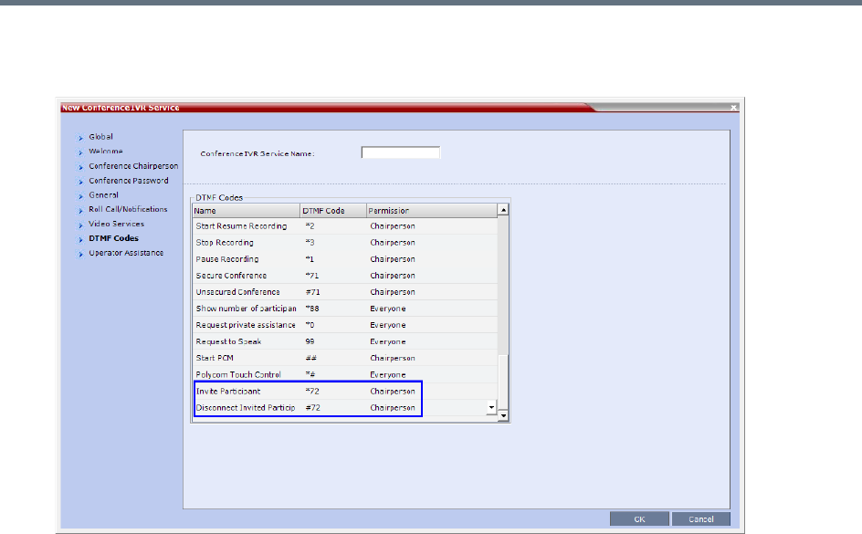
IVR Services
Polycom®, Inc. 609
6Click the DTMF Codes tab.
The IVR Services - DTMF Codes tab is displayed.
7Make sure that Invite Participant and Disconnect Invited Participant have DTMF Codes
assigned to them. Default system values are *72 (Invite Participant) and #72 (Disconnect Invited
Participant), however you can enter your own values.
When upgrading from a previous version, default system values may not be assigned if these IVR
entries were not defined in your existing IVR Service and have to be manually added to the DTMF
Codes table.
8If required, determine who can invite other participants to the conference using DTMF codes by
changing the permissions to either Chairperson or Everyone.
9Click OK.
Disabling the Invite Participant Option
To disable the Invite Participant option:
1From the IVR Services - DTMF Codes tab, delete the DTMF digits from the DTMF Code column.
2Click OK.

IVR Services
Polycom®, Inc. 610
External IVR Service Control
IVR Services can be controlled externally from an application server supporting the MCCF-IVR (Media
Control Channel Framework-Interactive Voice Response) package. The external IVR service is currently
being implemented with the integration of the Polycom RealPresence Virtualization Manager (DMA) as the
application server. When the application server is deployed in the enterprise environment and the Polycom
RealPresence Collaboration Server (MCU) is deployed as a media server, the external IVR service can be
used to play audio messages, display slides, and collect DTMF input from the participant.
For more information, see Using External IVR Services via the MCCF-IVR Package.
IVR Services Support with TIP Protocol
From Version 8.1, Conference IVR and Entry Queue IVR Services are supported with AVC TIP protocol in
conferences that include both TIP-enabled and non-TIP-enabled endpoints. TIP-enabled endpoints can be
moved from the Entry Queue to the destination conference if the TIP Compatibility Modes settings in the
Profile are identical for both conferencing entities (it is recommended to use the same Profile for both
entities).
The IVR services can be enabled in Prefer TIP TIP Compatibility Modes.
IVR media files, WAV for voice messages and JPG for video slides, are all stored on the RealPresence
Collaboration Server (RMX).
Guidelines for TIP Support with IVR Services
●AVC SIP and TIP protocols are supported on the RealPresence Collaboration Server
1500/2000/4000 only.
●IVR default audio files are enabled in Prefer TIP TIP Compatibility Modes.
●TIP-enabled endpoints can send DTMF digits to MCU.
●In a mixed TIP environment, there is no support for content in cascaded conferences. Additionally,
Legacy and Lync endpoints cannot view content.

IVR Services
Polycom®, Inc. 611
Default IVR Prompts and Messages
The system is shipped with the following audio prompts and messages:
Default IVR Messages
Message Type Message Text When Played File Name
General
Welcome
Message
Welcome to unified conferencing. The participant
enters the
conference IVR
queue
General_Welcome.wav
Chairperson
Identifier
Request
For conference Chairperson Services,
Press the Pound Key. All other
participants please wait...
The participant is
asked to
self-identify as the
chairperson
Chairperson_ Identifier.wav
Request
Chairperson
Password
Please enter the Conference
Chairperson Password. Press the
pound key when complete.
The participant is
asked for the
chairperson
password
Chairperson_Password.wav
Retry
Chairperson
Password
Invalid chairperson password. Please
try again.
A participant
enters an
incorrect
Chairperson
password
Chairperson_Password_Failure.
wav
Request
Password
Please enter the conference
password. Press the pound key when
complete.
A participant is
requested to
enter the
conference
password
Conference_ Password.wav
Retry Password Invalid conference password. Please
try again.
An incorrect
conference
password is
entered
Retry_
Conference_Password.wav
Request Digit Press any key to enter the
conference.
A participant is
requested to
press any key
Request_Digit.wav
Request Billing
Code
Please enter the Billing code. Press
the pound key when complete.
A participant is
asked to enter a
billing code
Billing_Code.wav
Requires
Chairperson
Please wait for the chairperson to join
the conference.
A participant
attempts to join a
conference prior
to the
Chairperson
joining
Requires Chairperson.wav

IVR Services
Polycom®, Inc. 612
Chairperson Exit The chairperson has left the
conference.
Note: The
TERMINATE_CONF_AFTER_CHAIR
_DROPPED flag must be enabled to
play this message.
The chairperson
has left the
conference.
Chairperson_Exit.wav
First to Join You are the first person to join the
conference.
The first
participant joins a
conference
First to Join.wav
Mute All On All conference participants are now
muted.
When all
participants are
muted by the
operator or
chairperson.
Mute_All_On.wav
Mute All Off All conference participants are now
unmuted.
When all
participants are
unmuted by the
operator or
chairperson.
Mute_All_Off.wav
End Time Alert The conference is about to end. The conference is
about it end
End_Time_Alert.wav
Change
Password Menu
Press one to change conference
password.
Press two to change chairperson
password.
Press nine to exit the menu.
A participant
requests a
conference
password change
Change_Password_ Menu.wav
Change
Conference
Password
Please enter the new conference
password. Press the pound key when
complete.
A participant
presses two in the
Change
Password IVR
menu.
Change_
Conference_Password.wav
Change
Chairperson
Password
Please enter the new chairperson
password. Press the pound key when
complete.
A participant
presses one in
the Change
Password IVR
menu.
Change_
Chairperson_Password.wav
Confirm
Password
Change
Please re-enter the new password.
Press the pound key when complete.
A participant
enters a new
conference or
chairperson
password
Confirm_
Password_Change.wav
Default IVR Messages
Message Type Message Text When Played File Name

IVR Services
Polycom®, Inc. 613
Change
Password
Failure
The new password is invalid. A participant
enters an invalid
password
Change_
Password_Failure.wav
Password
Changed
Successfully
The password has been successfully
changed.
A participant has
confirmed a
password change
Password_
Changed_Successfully.wav
Self Mute You are now muted. A participant
mutes his or her
audio
Self_Mute.wav
Self Unmute You are no longer muted. A participant
unmutes his or
her audio
Self_Unmute.wav
Chairperson
Help Menu
The available touch-tone keypad
actions are as follows:
•To exit this menu press any key.
•To request private assistance,
press star, zero.
•To request operator’s assistance
for the conference, press zero,
zero.
•To mute your line, press star, six.
•To unmute your line, press pound,
six.
A chairperson
requests the
chairperson help
menu
Chairperson_ Help_Menu.wav
Participant Help
Menu
The available touch-tone keypad
actions are as follows:
•To exit this menu press any key.
•To request private assistance,
press star, zero.
•To mute your line, press star, six.
•To unmute your line, press pound,
six.
•To increase your volume, press
star, nine.
•To decrease your volume, press
pound, nine.
A participant
requests the
participant help
menu
Participant_Help_Menu.wav
Maximum
Participants
Exceeded
The conference is full. You cannot join
at this time.
A participant
attempts to join a
full conference
Maximum_
Participants_Exceeded.wav
Roll Call Record
After the tone, please state your
name.
Roll_Call_Record.wav
Roll Call Joined ...has joined the conference. Roll_Call _Joined.wav
Roll Call Left ...has left the conference. Roll_Call_Left.wav
Default IVR Messages
Message Type Message Text When Played File Name

IVR Services
Polycom®, Inc. 614
Roll Call Review The conference participants are... Roll_Call_ Review.wav
Request
Conference NID
“Please enter your conference NID.
Press the pound key when complete.
Request_ Conference_NID.wav
Retry
Conference NID
Invalid conference NID. Please try
again.
A participant
enters an invalid
conference NID
Retry_Conference_NID.wav
Secured
Conference
The conference is now secured. A chairperson or
participant
secures a
conference
Conference_Secured.wav
Unsecured
Conference
The conference is now in an
unsecured mode
A chairperson or
participant
unsecures a
conference
Conference_Unsecured.wav
Locked
Conference
Conference you are trying to join is
locked
Conference_Locked.wav
Conference
Recording
The conference is being recorded Recording_ in_Progress.wav
Conference
Recording Failed
The conference recording has failed Recording_Failed.wav
No Video
Resources Audio
Only.
All video resources are currently in
use. Connecting using audio only
No_Video_Resources_Audio_O
nly.wav
Default IVR Messages
Message Type Message Text When Played File Name

IVR Services
Polycom®, Inc. 615
Volume Control of IVR Messages, Roll Call and Music
The volume of IVR music, and IVR messages and Roll Call is controlled by the following system flags:
●IVR_MUSIC_VOLUME
●IVR_MESSAGE_VOLUME
●IVR_ROLL_CALL_VOLUME
To control the volume of IVR music, Roll Call and messages:
»Modify the values of the System Flags listed in the following table by selecting Setup > System
Configuration.
If these flags do not appear in the System Flags list, they must be manually added. For more
information see System Configuration Flags.
Default IVR Messages
Flag Description
IVR_MUSIC_VOLUME The volume of the IVR music played when a single participant is
connected to the conference varies according to the value of this flag.
Possible value range: 0-10 (Default: 2).
0 – disables playing the music
1 – lowest volume
10 – highest volume
IVR_MESSAGE_VOLUME The volume of IVR messages varies according to the value of this
flag.
Possible value range: 0-10 (Default: 2).
0 – disables playing the IVR messages
1 – lowest volume
10 – highest volume
Note:
It is not recommended to disable IVR messages by setting the flag
value to 0.
IVR_ROLL_CALL_VOLUME The volume of the Roll Call varies according to the value of this flag.
Possible value range: 0-10 (Default: 4).
0 – disables playing the Roll Call
1 – lowest volume
10 – highest volume
Note: It is not recommended to disable the Roll Call by setting the flag
value to 0.

IVR Services
Polycom®, Inc. 616
IVR Services in TIP-Enabled Conferences
Conference IVR and Entry Queue/Virtual Entry Queues are supported with AVC TIP protocol in conferences
that include both TIP-enabled and non-TIP-enabled endpoints.
A Virtual Entry Queue can be configured to either IVR Only Service Provider or External IVR Control mode.
TIP-enabled endpoints can be moved from the Entry Queue to the destination conference if the TIP
Compatibility Modes settings in the Profile are identical for both conferencing entities (it is recommended
to use the same Profile for both entities).
TIP IVR users can access the conference directly or enter the Entry Queue/Virtual Entry Queue and provide
a password to access the conference.
The IVR services can be enabled with Prefer TIP.
IVR media files, WAV for voice messages and JPG for video slides, are all stored on the RealPresence
Collaboration Server (RMX).
IVR Services in TIP-Enabled Conferences Guidelines
●IVR default audio files are enabled for all TIP Compatibility Modes.
●TIP-enabled endpoints can send DTMF digits to MCU.
●In a mixed TIP environment there is no support for content in cascaded conferences. Additionally,
Legacy and Lync endpoints cannot view content.
Entry Queue and Virtual Entry Queue Access
TIP endpoints can dial-in to conferences directly using the IVR, Entry Queue/Virtual Entry Queue and IVR
Only Service Provider. For more information see Defining a New Entry Queue
For more information on Multipoint see the .
Configuring the Conference and Entry Queue IVR Services
The IVR module includes two types of services:
●Conference IVR Service that is used with conferences
●Entry Queue IVR Service that is used with Entry Queues
The configuration process is the same for TIP and non-TIP enabled Conferences and Entry Queues.
For more information about IVR Services see, Defining a New Conference IVR Service.
For more information about Entry Queues see, Entry Queues.
For more information see Appendix I - Polycom Open Collaboration Network (POCN).
The following System Flags do not require an MCU reset:
• IVR_MESSAGE_VOLUME
• IVR_MUSIC_VOLUME
• IVR_ROLL_CALL_VOLUME
For all other flag changes, the MCU must be reset for the modified flag settings (including deletion) to
take effect.

Polycom®, Inc. 617
Call Detail Record (CDR) Utility
The Call Detail Record (CDR) utility enables you to view summary information about conferences, and
retrieve full conference information and archive it to a file. The file can be used to produce reports or can be
exported to external billing programs.
The Collaboration Server can store details of up to 2000 (RealPresence Collaboration Server (RMX)
1500/1800/2000) or 4000 (RealPresence Collaboration Server (RMX) 4000)conferences. When this
number is exceeded, the system overwrites conferences, starting with the earliest conference. To save the
conferences’ information, their data must be retrieved and archived. The frequency with which the archiving
should be performed depends on the volume of conferences run by the MCU.
The Collaboration Server displays Active Alarms before overwriting the older files, enabling the users to
backup the older files before they are deleted. The display of Active Alarms is controlled by the
ENABLE_CYCLIC_FILE_SYSTEM_ALARMS system flag.
If the ENABLE_CYCLIC_FILE_SYSTEM_ALARMS is set to YES (default setting when
ULTRA_SECURE_MODE system flag is set to YES) and a Cyclic File reaches a file storage capacity limit,
an Active Alarm is created: Backup of CDR files is required.
Each conference is a separate record in the MCU memory. Each conference is archived as a separate file.
Each conference CDR file contains general information about the conference, such as the conference
name, ID, start time and duration, as well as information about events occurring during the conference, such
as adding a new participant, disconnecting a participant or extending the length of the conference.
The CDR File Properties
The output of a CDR file depends on the format in which the file was archived and the size of the file.
CDR File Formats
The conference CDR records can be retrieved and archived in the following two formats:
●Unformatted data – Unformatted CDR files contain multiple records in raw data format. The first
record in each file contains general conference data. The remaining records contain event data, one
record for each event. Each record contains field values separated by commas. This data can be
transferred to an external program such as Microsoft Excel for billing purposes. The following is a
sample of an unformatted CDR file.
Unformatted CDR File
The value of the fields that support Unicode values, such as the info fields, will be stored in the CDR
file in UTF8. The application that reads the CDR must support Unicode.
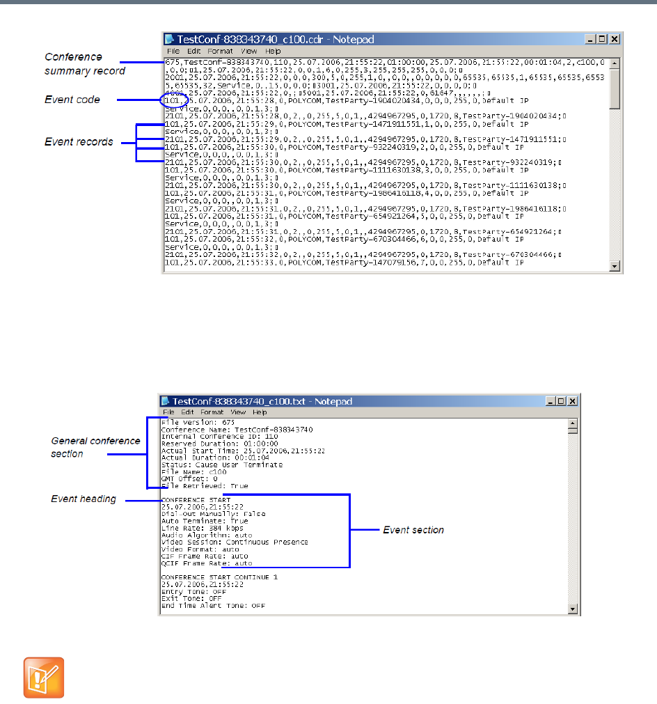
Call Detail Record (CDR) Utility
Polycom®, Inc. 618
●Formatted text – Formatted CDR files contain multiple sections. The first section in each file contains
general conference data. The remaining sections contain event data, one section for each event.
Each field value is displayed in a separate line, together with its name. This data can be used to
generate a summary report for a conference. The following is an example of a formatted CDR file.
Formatted CDR File
Multi-Part CDR Files
By default, the maximum CDR (Call Data Record) file size is limited to 1MB. When a CDR file reaches a
size of 1MB the file is saved and further call data recording is stopped and the additional data is lost.
The Collaboration Server can be configured to keep recording the data in multiple CDR file set of 1MB each.
Multi-Part CDR ensures that conference call data from long duration or permanent conferences is recorded
and not lost.
The field names and values in the formatted file will appear in the language being used for the
Collaboration Server Web Client user interface at the time when the CDR information is retrieved.

Call Detail Record (CDR) Utility
Polycom®, Inc. 619
Enabling the Multi-Part CDR Option
●Multi-Part CDR is enabled by setting the value of ENABLE_MULTI_PART_CDR system flag to YES.
The flag’s default value is NO.
When flag value is NO, CDR storage is limited to a single 1MB file. Further call data recording stops.
To modify the default setting, the flag must be manually added to the System Configuration. For more
information see, Modifying System Flags.
●If the flag value is set to YES, when a CDR file reaches 1MB, an additional CDR file is created and
added to the CDR file set for that conference.
●If the flag value is changed from YES to NO (or visa versa) all existing CDR files are retained.
CDR File Contents
The general conference section or record contains information such as the Routing Name and ID, and the
conference starting date and time.
The event sections or records contain an event type heading or event type code, followed by event data.
For example, an event type may be that a participant connects to the conference, and the event data will
list the date and time the participant connects to the conference, the participant name and ID, and the
participant capabilities used to connect to the conference.
To enable compatibility for applications that written for the MGC family, the Collaboration Server CDR file
structure is based on the MGC CDR file structure.
The unformatted and formatted text files contain basically the same information. The following differences
should be noted between the contents of the unformatted and formatted text files:
●In many cases a formatted text file field contains a textual value, whereas the equivalent unformatted
file field contains a numeric value that represents the textual value.
●For reading clarity, in a few instances, a single field in the unformatted file is converted to multiple
fields in the formatted text file, and in other cases, multiple fields in the unformatted file are combined
into one field in the formatted file.
●To enable compatibility between MGC CDR files and Collaboration Server CDR files, the unformatted
file contains fields that were applicable to the MGC MCUs, but are not supported by the Collaboration
Server MCUs. These fields are omitted from the formatted text file.
Appendix C - CDR Fields, Unformatted File Appendix contains a full list of the events, fields and
values that appear in the unformatted file. This appendix can be referred to for information regarding
the contents of fields in the unformatted text file, but does not reflect the exact contents of the
formatted text file.
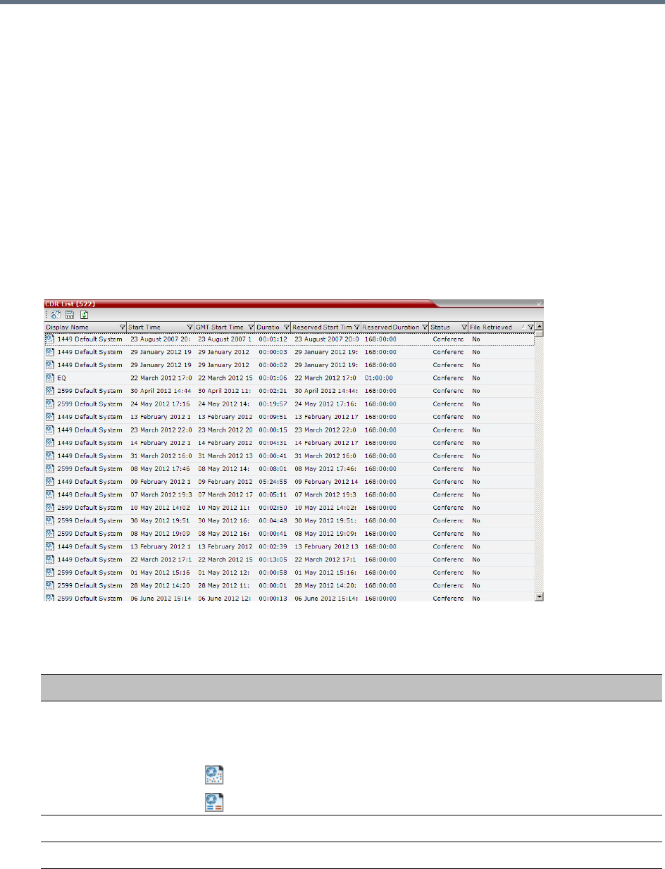
Call Detail Record (CDR) Utility
Polycom®, Inc. 620
Viewing, Retrieving and Archiving Conference
Information
You can view the list of CDR files and retrieve them to your local workstation. These files can then be used
to generate billing information, resource usage reports and more by any third party application.
Viewing the Conference Records
You can list all the CDR files that are currently saved on the MCU.
To open the CDR utility:
»On the Collaboration Server Menu, click Administration > CDR.
The CDR List pane opens, displaying a list of the conference CDR records stored in the MCU.
The following fields are displayed:
Conference Record Fields
Field Description
Display Name The Display Name of the conference and an icon indicating whether or not the
CDR record has been retrieved and saved to a formatted text file.
The following icons are used:
The CDR record has not been saved.
The CDR record has been saved.
Start Time The time the conference started.
GMT Start Time The time the conference started according to Greenwich Mean Time (GMT).
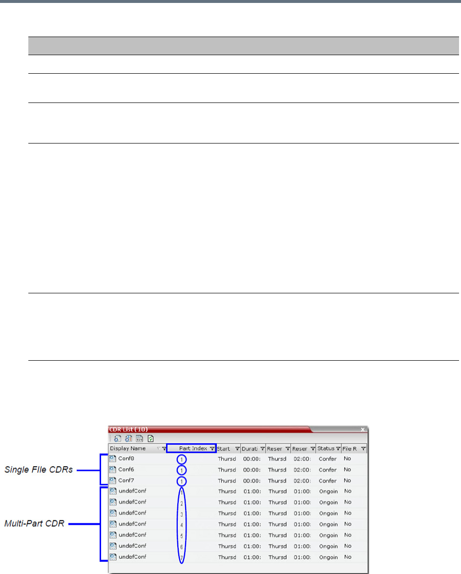
Call Detail Record (CDR) Utility
Polycom®, Inc. 621
Multi-part CDR File display
When the Multi-Part CDR is configured on the Collaboration Server, an additional column, Part Index is
added to the CDR list.
The Part Index column displays the CDR file’s sequence in the CDR file set:
●CDRs up to 1MB consist of a single file. Each file has a unique Display Name and a Part Index of 1.
Duration The actual conference duration.
Reserved Start Time The reserved start time of the conference. If the conference started immediately
this is the same as the Start Time.
Reserved Duration The time the conference was scheduled to last. Discrepancy between the
scheduled and the actual duration may indicate that the conference duration was
prolonged or shortened.
Status The conference status. The following values may be displayed:
•Ongoing Conference
•Terminated by User
•Terminated when end time passed
•Automatically terminated when conference was empty – The conference
ended automatically because no participants joined the conference for a
predefined time period, or all the participants disconnected from the
conference and the conference was empty for a predefined time period.
•Conference never became ongoing due to a problem
•Unknown error
Note: If the conference was terminated by an MCU reset, the status Ongoing
Conference will be displayed.
File Retrieved Indicates if the conference record was downloaded using any of the file retrieval
buttons in the CDR List pane or the API.
•Yes - when the conference record was retrieved to any file or using the API.
•No - when the conference record was not retrieved at all.
The File Retrieved field is updated whenever the record is downloaded.
Conference Record Fields
Field Description
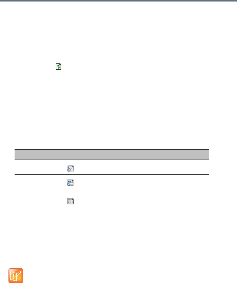
Call Detail Record (CDR) Utility
Polycom®, Inc. 622
●Files included in a Multi-Part CDR file sets have the same Display Name. The first file of the set is
numbered 1 with each additional CDR file numbered in an ascending numeric sequence.
Refreshing the CDR List
If the CDR file list remains constant too long, you can refresh the list to view the latest CDR files.
To refresh the CDR list:
»Click the Refresh button, or right-click on any record and then select Refresh.
Updated conference CDR records are retrieved from the MCU memory.
Retrieving and Archiving Conference CDR Records
You can retrieve the CDR files and store them on your workstation for later use.
To retrieve and archive CDR records:
1To retrieve a single CDR record, right-click the record to retrieve, and select the required format or
the record to retrieve. Then, click the appropriate button on the toolbar as detailed in the table below.
To retrieve multiple CDR records simultaneously, use standard Windows multi-selection methods.
The Retrieve dialog box opens.
The dialog box displays the names of the destination CDR files.
2Select the destination folder for the CDR files and then click OK.
If the destination file already exists, you will be asked if you want to overwrite the file or specify a new
name for the destination file.
The files are saved to the selected folder.
Menu Option Button Action
Retrieve Retrieves the conference information as unformatted data
into a file whose extension is .cdr.
Retrieve Formatted
XML
Retrieves the conference information as formatted text
into a file whose extension is .xml.
Note: Viewed when logged in as a special support user.
Retrieve Formatted Retrieves the conference information as formatted text
into a file whose extension is .txt.
CDR files are not included in the backup process and should be backed up manually by saving the
CDR files to a destination device.

Polycom®, Inc. 623
Gateway Calls
The RealPresence Collaboration Server (RMX) can be used as a gateway that provides connectivity across
different physical networks and translates multiple protocols for point-to-point rich media communications.
The Collaboration Server supports a range of video and audio algorithms. It allows sites with different frame
rates, connection speeds, audio algorithms, video resolutions and network protocols to transparently
connect with one another. It also enables multipoint conference creation from an endpoint.
A special conference acting as a Gateway Session is created on the Collaboration Server. It includes one
dial-in connection of the endpoint initiating the Gateway Session and one or several dial-out connections to
endpoints. It provides connectivity between the various protocols: H.323, SIP, ISDN and PSTN.
To enable the gateway functionality a special Gateway Profile is defined on the Collaboration Server.
Gateway Functionality
The following features and capabilities are supported in gateway calls:
●Gateway Sessions are in CP Mode only.
If Video Switching is selected in the Profile assigned to the Gateway Session, the system ignores this
setting and will run the Gateway Session in CP mode.
Gathering phase is not supported in gateway calls, even if it is defined in the Profile assigned to
the Gateway Profile.
●Sharing Content using H.239 protocol
●FECC.
Note: Only IP participants can use FECC as it is not supported by the ISDN protocol.
●Recording.
Note: The Recording Link is not considered as a participant and therefore, the gateway session will
automatically end when only one of the participants remains connected in addition to the recording
link. The video of the Recording Link is not included in the display of the video of the gateway call.
●Forwarding of DTMF codes from the Gateway Session to a conference running on another gateway,
MCU or DMA. This enables the participant to enter the required conference and/or chairperson
password when connecting to another conference.
DTMF forwarding is enabled when there are only two participants connected to the Gateway Session.
●Forwarding of all DTMF codes sent by participants in the Gateway Session to all PSTN and ISDN
participants. This is enabled by adding the
ALWAYS_FORWARD_DTMF_IN_GW_SESSION_TO_ISDN System Flag to system.cfg and
setting its value to YES.
●Up to 80 gateway calls may be run on a fully configured MCU.
●Gateway Profiles are included in the Backup and Restore Configuration operations.
Note: Gateway Functionality
Gateway calls are supported with AVC calls only.
Gateway functionality is not supported by Collaboration Server (RMX) 1800-0.

Gateway Calls
Polycom®, Inc. 624
●CDR files are generated for Gateway Sessions in the same way as for conferences.
●Cascading. To support cascading, the gateway indicates a lower number than the MCU for
master-slave relation (directly or through DMA).
●Gateway calls are supported in Microsoft and Avaya environments.
●If the ENABLE_AUTO_EXTENSION system flag is set to:
YES (default), Gateway Calls are not limited in duration while endpoints are connected.
NO, Gateway Calls are limited to 60 minutes.
For more information see Modifying System Flags.
Call Flows
Call flow changes according to the connection protocols: IP or ISDN. This section describes the call flows
between two endpoints connect via one gateway. For call flows describing connections between two
endpoints via two gateways, or a connection of an endpoint to a conference running on MCU via a gateway,
see Basic Cascading Using ISDN Cascaded Link.
IP Participants
The following calling methods are available:
●Direct Dialing - the dialing string includes the destination number/conference ID and the call is routed
directly to the destination endpoint/conference. This is the recommended method.
●Gateway IVR Dialing For IP Participants - the call connects to the gateway, where through interaction
with the IVR, the destination number is entered using DTMF codes.
●Direct Dialing Using IP Addresses - dial and receive calls to and from H.323 endpoints using the IP
address when that the Gatekeeper is not functioning
●Calling a SIP Endpoint in a Remote Domain - connection of H.323 and SIP endpoints residing in one
domain to SIP endpoints residing in a remote domain
Direct Dialing
The calling endpoint enters the dialing string that includes the access numbers to the Collaboration Server
Gateway Profile and the number of the destination endpoint. Up to 10 destination numbers can be entered
in one string.
The call connects to the Collaboration Server Gateway Profile and a Gateway Session is created. The
dial-in participant is automatically connected to it.
During the connection phase, the number being dialed is displayed on the screen of the calling endpoint.
If the call is not answered or it cannot be completed using one communication protocol, the system will try
to connect the endpoint using the next communication protocol according to the selected protocols in the
following order: H.323, SIP and ISDN. PSTN numbers are identified separately and are dialed immediately
without trying other connections.
If the call is busy, the system will not try to connect the endpoint using another protocol.
If the call is not completed after trying all possible protocols, the system displays the number that was dialed
on the calling endpoint’s screen and the reason for not completing the call. For details, see Connection
Indications.
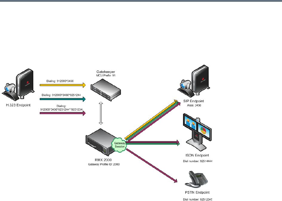
Gateway Calls
Polycom®, Inc. 625
When the call is connected, a new Gateway Session is created and added to the ongoing Conferences list.
Dialing from H.323 Endpoints
The calling endpoints can dial to one, two or several endpoints (up to ten) in one dialing string.
Dialing String and Call Flow from H.323 Endpoint to One, Two or Three Endpoints
The dialing string includes the following components:
[MCU prefix in GK] - the prefix with which the Collaboration Server is registered to the gatekeeper.
[GW Profile ID] - The ID of the Gateway Profile to be used for routing the call to the destination endpoint
or DMA, as defined in the Collaboration Server Gateway Profiles. It includes the parameters of the call to
the destination.
* - indicates H.323, SIP or ISDN connection protocol to the destination endpoint (followed by the appropriate
destination number). Placing this delimiter before the destination number causes the system to try to
connect the endpoint using H.323 first, then SIP and lastly ISDN according to the selected protocols.
** - indicates a PSTN connection to the destination endpoint (followed by the appropriate destination
number).
[Destination number] - the destination number as alias, IPv4 address or ISDN/PSTN number.
The dialing string:
[MCU prefix in GK][GW Profile ID]*[Destination Number, first
participant]*[Destination Number, second participant]**[Destination
number]......*[Destination Number, tenth participant]
For example, If the MCU Prefix in the GK is 91 and the GW Profile ID is 2000, and the destination number
is 3456 (SIP) enter: 912000*3456.
To invite two participants: SIP: 3456 and ISDN: 9251444, enter: 912000*3456*9251444.
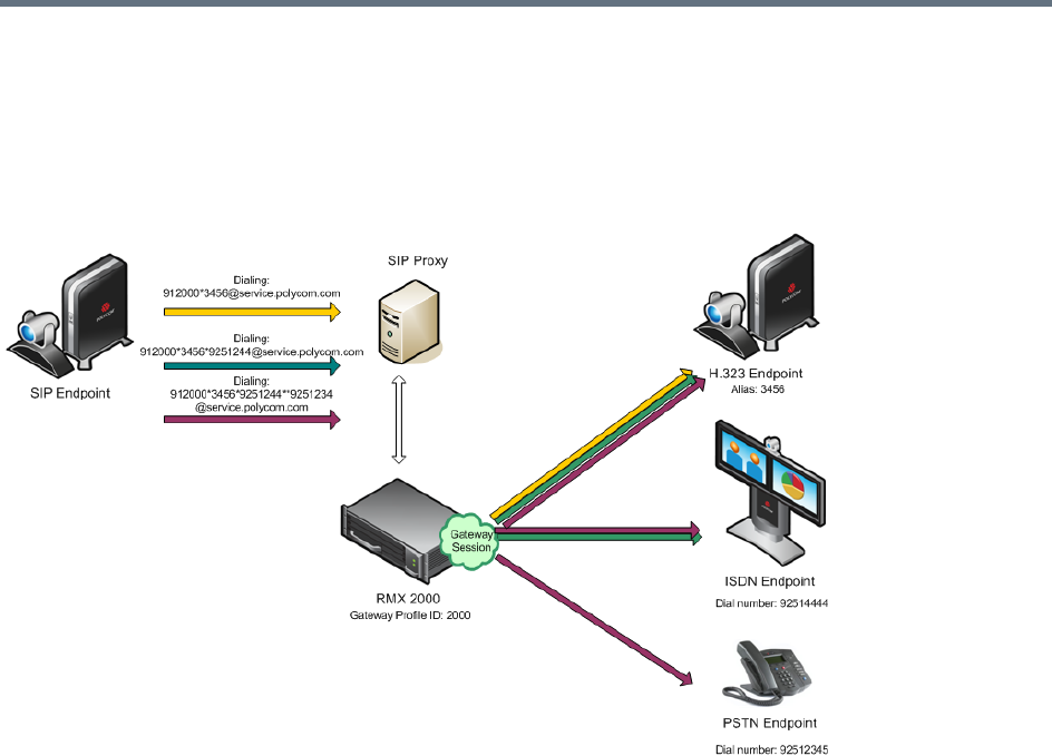
Gateway Calls
Polycom®, Inc. 626
To invite two participants: SIP: 3456 and a PSTN participant whose number is 9251234, enter:
912000*3456**9251234.
Dialing from SIP Endpoints
Dialing String and Call Flow from SIP Endpoint to One, Two or Three Endpoints
The calling endpoints can dial to one, two or several endpoints (up to ten) in one dialing string. The dialing
string includes the following components:
[MCU Prefix in SIP Proxy] - The prefix with which the Collaboration Server is registered to the SIP
Proxy. This component is optional and is not required in most cases.
[GW Profile ID] - The ID of the Gateway Profile to be used for routing the call to the destination endpoint
or DMA, as defined in the Collaboration Server Gateway Profiles. It includes the parameters of the call to
the destination.
* - indicates H.323, SIP or ISDN connection protocol to the destination endpoint (followed by the appropriate
destination number). Placing this delimiter before the destination number causes the system to try to
connect the endpoint using H.323 first, then SIP and lastly ISDN according to the selected protocols.
** - indicates a PSTN connection to the destination endpoint (followed by the appropriate destination
number).
[Destination number] - the destination number as alias, IPv4 address or ISDN/PSTN number.
[@domain name] - the Collaboration Server domain name as registered to the SIP Proxy
The dialing string:
[GW Profile ID]*[Destination Number, first participant]*[Destination Number,
second participant]**[destination number]......*[Destination Number, tenth
participant]@domain name
Gateway Calls
Polycom®, Inc. 627
Optional:
[GW Profile ID]*[Destination Number, first participant]*[Destination Number,
second participant]**[destination number]......*[Destination Number, tenth
participant]@IP address of the Collaboration Server signaling host
Optional:
[MCU prefix in SIP Proxy][GW Profile ID]*[Destination Number, first
participant]*[Destination Number, second participant]**[destination
number]......*[Destination Number, tenth participant]@domain name
For example, if the GW Profile ID is 2000, the domain name is service.polycom.com, and the destination
number is 3456, enter: 2000*3456@service.polycom.com.
If using the IP address of the Collaboration Server signaling host (for example, 172.22.188.22) instead of
the domain name enter: 2000*3456@172.22.188.22.
To invite two participants IP: 3456 and ISDN: 9251444, enter: 2000*3456*9251444@service.polycom.com.
To invite two participants IP: 3456 and PSTN: 9251234, enter:
912000*3456**9251234@service.polycom.com.
Gateway IVR Dialing For IP Participants
Can be used by IP endpoints when the destination dialing string includes the address of the MCU only. This
is the same flow as the dialing method used for ISDN/PSTN calls, however it is less recommended for IP
participants. For details, see Dialing via Gateway IVR for ISDN Participants.
Dialing from H.323 Endpoints
Dialing String and Call Flow from IP Endpoint to ISDN Endpoint
[MCU prefix in GK] - the prefix with which the Collaboration Server is registered to the gatekeeper.
[GW Profile ID] - The ID of the Gateway Profile to be used for the gateway call and the IVR message.
The dialing string format is:
[MCU prefix in GK][GW Profile ID]
For example, if the MCU Prefix in the GK is 91 and the GW Profile ID is 2000 enter: 912000.

Gateway Calls
Polycom®, Inc. 628
Once the participant is connected to the Gateway Profile and hears the IVR message requesting the
destination number, using the DTMF input keypad, the participant enters the number of the destination
endpoint followed by the # key. PSTN numbers are identified by an * before the number.
For example, enter 3456# for IP endpoint, or 9253456# for ISDN, or *9253456# for PSTN phone.
To enter an IP address as the destination number, replace the periods (.) with asterisks (*) in the format
n*n*n*n followed by the # key. For example, if the IP address is 172.22.188.22, enter 172*22*188*22#.
Dialing from SIP Endpoints
[MCU prefix in SIP Proxy] - the prefix with which the Collaboration Server is registered to the
gatekeeper. [Optional.]
[GW Profile ID] - The ID of the Gateway Profile to be used for the gateway call and the IVR message.
[@domain name] - the Collaboration Server domain name as registered to the SIP Proxy.
The dialing string:
[GW Profile ID]@domain name
Optional:
[GW Profile ID]@IP address of the Collaboration Server signaling host
Optional:
[MCU prefix in SIP proxy][GW Profile ID]@domain name
Once the participant is connected to the Gateway Profile and hears the IVR message requesting the
destination number, using the DTMF input keypad, the participant enters the number of the destination
endpoint followed by the # key. PSTN numbers are identified by an * before the number.
For example, enter 3456# for IP endpoint, or 9253456# for ISDN, or *9253456# for PSTN phone.
To enter an IP address as the destination number, replace the periods (.) with asterisks (*) in the format
n*n*n*n followed by the # key. For example, if the IP address is 172.22.188.22, enter 172*22*188*22#.
Direct Dialing Using IP Addresses
For Collaboration Servers registered to a gatekeeper, the Collaboration Server can be configured to dial and
receive calls to and from H.323 endpoints using the IP address in the event that the Gatekeeper is not
functioning.
Dial-out Calls
For Dial-out calls, direct IP dialing is enabled or disabled by the GK_MANDATORY_FOR_CALLS_OUT
system flag.

Gateway Calls
Polycom®, Inc. 629
When the flag is set to NO (default), if the Gatekeeper is not functioning, the Collaboration Server dials to
the endpoint using the endpoint’s IP address configured in the IP Address field of the New
Participant/Participant Properties - General dialog box.
If no IP address is defined in the Participant Properties, the call will fail.
The method by which calls are dialed out to the endpoint is dependant on the flag value and the availability
of the Gatekeeper as summarized in the following table:
Dial-in Calls
For Dial-in calls, direct IP dialing is enabled or disabled by the GK_MANDATORY_FOR_CALLS_IN and
system flag.
Determination of Method for Dialing an Endpoint by Flag and Gatekeeper Availability
Flag Value
Gatekeeper
Available Results
NO NO Dial out to endpoint IP Address bypassing the Gatekeeper.
NO YES Dial out to endpoint Alias Name using the Gatekeeper.
YES NO No dial out to endpoint.
YES YES Dial out to endpoint Alias Name using the Gatekeeper.
Gateway Calls
Polycom®, Inc. 630
When the flag is set to NO (default), if the Gatekeeper is not functioning, calls from endpoints will be
connected directly to the Entry Queue, Conference or Meeting Room that was dialed.
The method by which dial-in calls are accepted or rejected is dependant on the flag value and the availability
of the Gatekeeper as summarized in the following table.
Enabling or Disabling Direct IP Dialing
The direct IP dialing is enabled by default. To disable it, manually add the flags
GK_MANDATORY_FOR_CALLS_OUT and GK_MANDATORY_FOR_CALLS_IN to the System
Configuration - MCMS_PARAMETERS dialog box and for each flag enter the required value (YES or NO).
For more information on flag definition, see Modifying System Flags.
Calling a SIP Endpoint in a Remote Domain
The Gateway functionality allows the connection of H.323 and SIP endpoints to SIP endpoints residing in a
remote domain, different to that of the MCU’s domain.
This functionality can be enabled when:
●The calling endpoint may be H.323 or SIP.
●The destination endpoint must be SIP.
●The dial string from the calling endpoint to the Collaboration Server includes the gateway dial-out
number of the SIP endpoint that is located in the remote domain.
By definition, a dial-in string cannot contain two domains and it is therefore necessary that the dial string be
of the following format:
mcu-meeting-room*dest%40dest-domain@mcu-domain
Where:
●The domain of the gateway call is mcu-domain
●The remote destination domain is dest%40dest-domain.
●The “%40” is replaced with an “@” when the gateway call is dialed to the remote SIP destination.
GK_MANDATORY_FOR_CALLS_IN - System Flag
Flag Value Gatekeeper Available Results
NO NO Dial-in call is connected bypassing the Gatekeeper.
NO YES Dial-in call is connected using the Gatekeeper.
YES NO Dial-in call is rejected.
YES YES Dial-in call is connected using the Gatekeeper.
For flag changes (including deletion) to take effect, reset the Collaboration Server. For more
information see Resetting the Collaboration Server.
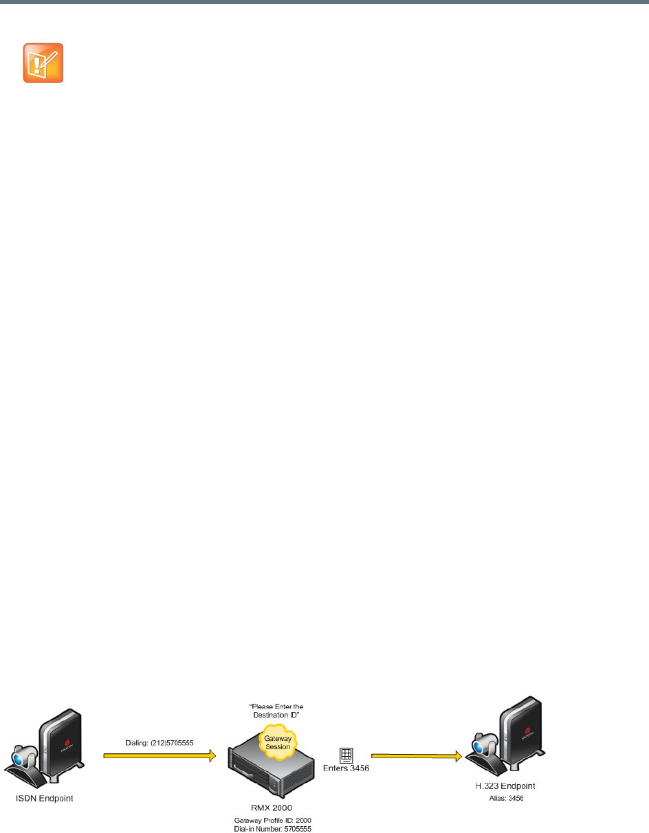
Gateway Calls
Polycom®, Inc. 631
ISDN Participants
Two dialing methods are available to ISDN/PSTN participants:
●Dialing via Gateway IVR for ISDN Participants
●Direct Dial-in to Endpoints or DMA VMR using Automatically Generated Destination Numbers.
In addition, PSTN participants can dial the Gateway IVR and can use the MCU or DMA prefix in the
gatekeeper together with the conference ID/endpoint alias as the destination string to simplify the input. This
is one of the methods for PSTN participants to connect to a virtual Meeting Room on the DMA.
Dialing via Gateway IVR for ISDN Participants
In this flow, the calling endpoint enters the dialing string that includes the access number to the
Collaboration Server Gateway Profile.
The endpoint connects to the Collaboration Server and is welcomed by the IVR Welcome slide and
message: Please enter the destination number followed by the dial tone.
Using the endpoint’s DTMF input device such as remote control, the participant enters the number of the
destination endpoint followed by the # key. Only one number can be dialed.
While the system dials to the destination endpoints, the participant hears the dialing rings. During the
connection phase, the number being dialed is displayed on the screen of the calling endpoint.
If the call is not answered or it cannot be completed using one communication protocol, the system will try
to connect the endpoint using the next communication protocol according to the selected protocols in the
following order: H.323, SIP and ISDN.
PSTN numbers are identified separately and are dialed immediately without trying other connections.
If the endpoint is busy, the system will not try to connect the endpoint using another protocol.
If the call is not completed after trying all possible protocols, the system displays the number that was dialed
on the calling endpoint’s screen and the reason for not completing the call. For details, see Connection
Indications.
Dialing from ISDN/PSTN Endpoints
Dialing String and Call Flow from ISDN Endpoint to IP Endpoint
DTMF tones and Caller-id are not passed end-to-end.

Gateway Calls
Polycom®, Inc. 632
[GW Profile ISDN/PSTN number] - The dial-in number assigned to the Gateway Profile, including the
required country and area codes.
For example, if the dial-in number assigned to the Gateway Profile is 5705555, enter this number with the
appropriate area code: 2125705555.
Once the participant is connected to the Gateway Profile and hears the IVR message requesting the
destination number, using the DTMF input keypad, the participant enters the number of the destination
endpoint followed by the # key. For example, enter 3456# for IP endpoint.
To enter an IP address as the destination number, replace the periods (.) with asterisks (*) in the format
n*n*n*n followed by the # key. For example, if the IP address is 172.22.188.22, enter 172*22*188*22#.
PSTN Dial-in Using GK Prefix
When connecting to an Collaboration Server that is standalone or part of a DMA solution deployment, PSTN
participants are prompted by an IVR message requesting the Destination Conference ID followed by the
# key to be entered using the DTMF input keypad.
Including the Gatekeeper Prefix in the DTMF input string enables PSTN participants to use the input string
when connecting to an Collaboration Server whether the Collaboration Server is a standalone MCU or part
of a DMA solution deployment. For a detailed description, see PSTN Dial-in Using GK Prefix.
Direct Dial-in to Endpoints or DMA VMR using Automatically Generated
Destination Numbers
ISDN/PSTN participants can call the destination endpoints without interaction with the IVR of the gateway.
This dialing method is enabled when the administrator configures the Gateway Profile to automatically
generate the dial string of the destination endpoint or Meeting Room on the DMA by truncating the dial in
string and replacing the truncated digits by other digits that can be used as the destination number.
For a detailed description of the call flow when dialing the DMA using this method, see Calling a
RealPresence DMA Direct with Automatically Generated Destination Dial Strings.
Calling an IP Endpoint via Gateway
If the call destination is an IP endpoint, the endpoints must be registered to the same gatekeeper to which
the Collaboration Server is registered. There should be a mapping between the dial-in numbers in the range
defined for the ISDN Network Service and also assigned to the Gateway Profile and the IP endpoints, in
such a way that the alias of each endpoint is the number that will be appended to the ISDN prefix.
When the call arrives to the gateway, this prefix is truncated and replaced by digits that correspond to the
MCU prefix in the gatekeeper and the call is forwarded to the destination endpoint.
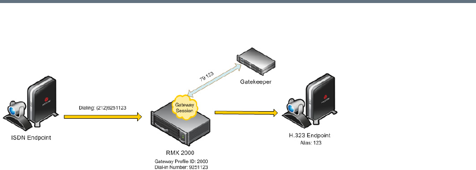
Gateway Calls
Polycom®, Inc. 633
Call Flow from ISDN Endpoint to H.323 Endpoint with Automatically Generated Forwarded Dial String
For example:
●The ISDN prefix is 9251.
●The dial in number range defined in the ISDN Network Service can be 100 to 400 (that is, 9251100
to 9251400).
●The dial in numbers assigned to the Gateway Profile can the entire range, or part of the range of other
Gateway Profiles are to be used: 100 to 200 (that is 9251100 to 9251200).
●The aliases assigned to the IP endpoints will range between 100 to 200 or 400 (for the full range) as
well.
●MCU Prefix in the gatekeeper: 79.
●Number of digits to append (same as the ISDN prefix is this example): 3.
●The destination endpoint alias is 123.
●The ISDN endpoint dials 9251123. The Collaboration Server truncates the four first digits 9251
replacing them with 79 and appends 123 to 79, to create the destination number 79123 which is sent
to the gatekeeper for routing.
Interoperability with DMA
The Collaboration Server does not register to the gatekeeper as a Gateway, therefore it is recommended to
create and use the DMA Dialing Rules to enable the DMA Dial One Method.
When the caller enters the Dial One digit as the destination number prefix, the DMA replaces this digit with
the MCU prefix in the Gatekeeper and the ID of the Gateway Profile. For example, the calling participant
can enter 99251444, where 9 is the digit that is used as the MCU prefix registered in gatekeeper and is
replaced by the gatekeeper with * and the Gateway Profile ID (for example, *2000) as defined in the Dialing
Rule.
For more details on Dialing Rules definition in the DMA, see Dial Rule Operations in the Polycom
RealPresence DMA System Operations Guide.

Gateway Calls
Polycom®, Inc. 634
Configuring the Gateway Components on the
Collaboration Server
To enable gateway calls in the Collaboration Server, the following components have to be configured:
●Conference IVR Service to be used with the Conference Profile assigned to the Gateway Profile. The
IVR Services are used for Gateway IVR connections.
●Conference Profile that includes the IVR Service for the Gateway Session and the settings to
automatically terminate the Gateway Session when one participant is still connected or when no
participants are connected
●Gateway Profile for call routing.
Defining the IVR Service for Gateway Calls
The system is shipped with a default Conference IVR Services for gateway calls named GW IVR Service
that enables you to run gateway calls without defining a new Conference IVR Service. This IVR Service
includes the following settings:
●Welcome slide and message - disabled
●Conference and Chairperson Passwords - disabled
●General Messages - all messages including the gateway messages and dial tones are selected
●Roll Call - disabled
●Video Services - Click&View - enabled
●Video Services - Video Welcome Slide - Default_GW_Welcom_Slide
●Operator Assistance - disabled
You can define a new Conference IVR Service to be used for gateway calls. This Conference IVR Service
will be assigned to the appropriate Gateway Profile.
To define a new Conference IVR Service for gateway calls:
1In the RMX Management - Rarely Used pane, click the IVR Services () entry.
The list pane displays the Conference IVR Services list.
2On the IVR Services toolbar, click New Conference IVR Service ().
The New Conference IVR Service - Global dialog box opens.
3In the Conference IVR Service Name field, enter a name that will identify this service as a gateway
IVR service.
4Define the IVR Service Global parameters (it is recommended to use the system defaults). For more
details, see Conference IVR Service Properties - Global Parameters.
5When defining a gateway IVR Service, the following options should remain disabled:
Welcome Messages (in the Conference IVR Service - Welcome dialog box).
Chairperson Messages (in the Conference IVR Service - Conference Chairperson dialog box).
Password Messages (in the Conference IVR Service - Conference Password dialog box)
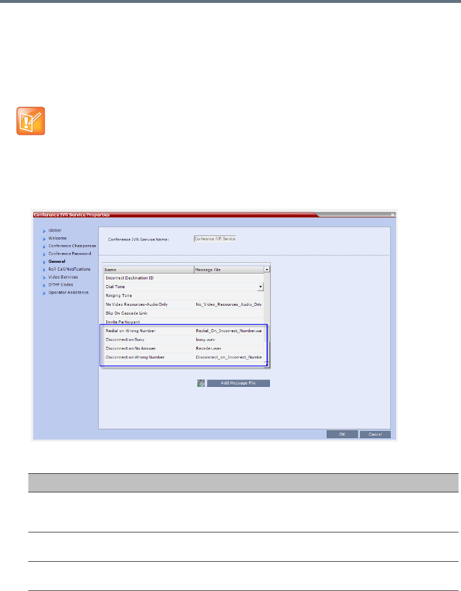
Gateway Calls
Polycom®, Inc. 635
6Click the General tab.
The General dialog box lists messages that are played during the conference. These messages are
played when participants or the conference chairperson perform various operations or when a
change occurs.
7To assign the appropriate audio file to the message type, click the appropriate table entry, in the
Message File column. A drop-down list is enabled.
8From the list, select the audio file to be assigned to the event/indication.
9Repeat steps 7 and 8 to select the audio files for the required messages.
10 For a gateway IVR Service, select the audio file for the following message types:
For gateway redial, ensure that the audio files for the gateway redial messages have been assigned.
Conference IVR Service Properties - Gateway General Voice Messages
Message Type Description
Enter Destination ID Prompts the calling participant for the destination number. Default message
prompts the participant for the conference ID (same message as in the Entry
Queue IVR Service).
Incorrect Destination
ID
If the participant entered an incorrect conference ID (in gateway calls it is the
destination number), requests the participant to enter the number again.
Dial Tone The tone that will be played to indicate a dialing tone, to let the calling participant
enter the destination number.

Gateway Calls
Polycom®, Inc. 636
11 When defining a gateway IVR Service, it is recommended that the Roll Call option remains
disabled.
12 Click the Video Services tab.
The New Conference IVR Service - Video Services dialog box opens.
13 Define the following parameters:
14 Click the DTMF Codes tab.
The New Conference IVR Service - DTMF Codes dialog box opens.
15 If required, modify the DTMF codes or permissions. For more details see New Conference IVR
Service Properties - DTMF Codes.
16 Click the Operator Assistance tab.
17 If Operator Assistance will not be available to participants, clear the Enable Operator Assistance
option, which is automatically selected to disable it.
Ringing Tone The tone that will be played to indicate that the system is calling the destination
number.
Redial on Wrong
Number
The message played when the wrong destination is entered, allowing you to enter a
new number. For details, see Redial on Wrong Number.
Disconnect on Wrong
Number
The message played when the wrong destination is entered, followed by a
disconnection tone. For details, see Disconnect on Wrong Number.
Disconnect on Busy The tone (or message) played when the dialed destination number is busy. For
details, see Disconnect on Busy.
Disconnect on No
Answer
The tone (or message) played when the dialed destination number does not
answer. For details, see Disconnect on No Answer
New Conference IVR Service Properties - Video Services Parameters
Video Services Description
Click&View Select this option to enable endpoints to run the Click&View application that enables
participants to select a video layout from their endpoint.
Video Welcome Slide Select the video slide file to be displayed when participants connect to the
conference. To view any slide, click the Preview Slide ( ) button.
If the video slide file was not uploaded to the MCU prior to the IVR Service
definition, click the Add Slide button. The Install File dialog box opens. The
uploading process is similar to the uploading of audio files. For more information,
see step 7.
Notes:
•When using one of the default Polycom slides, the slide will be displayed in the
resolution defined in the profile, i.e. CIF, SD, HD 720p or HD 1080p.
•When defining a gateway IVR Service, the recommended default slide is:
Default_GW_Welcome_Slide.
Conference IVR Service Properties - Gateway General Voice Messages
Message Type Description
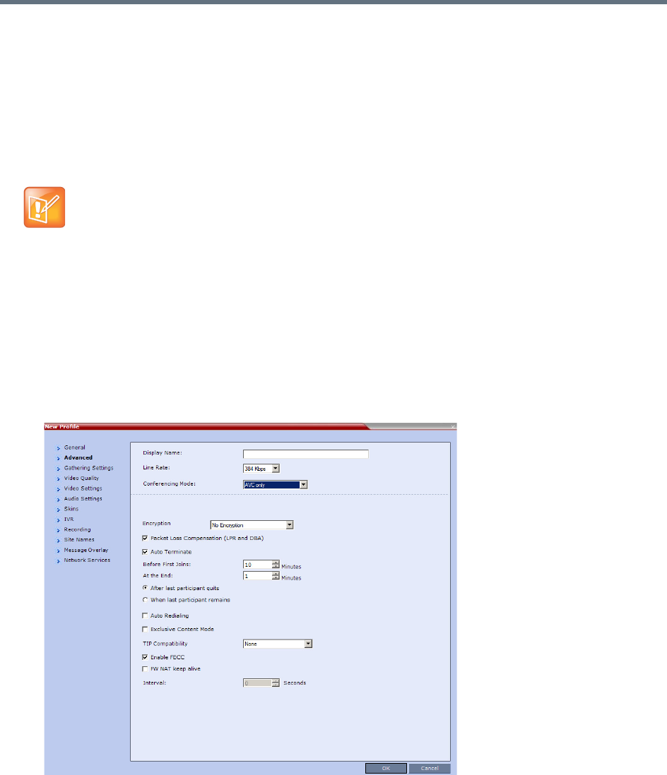
Gateway Calls
Polycom®, Inc. 637
18 Click OK to complete the IVR Service definition.
The new Conference IVR Service is added to the IVR Services list.
Defining the Conference Profile for Gateway Calls
The Conference Profile that will be later assigned to the Gateway Profile determine the parameters of the
gateway call, such as the line rate and video resolution and if to automatically terminate the gateway session
when one participant or no participants are connected to the Gateway Session.
To define a Conference Profile for Gateway Sessions:
1In the RMX Management - Rarely Used pane, click Conference Profiles.
2In the Conference Profiles pane, click New Profile.
The New Profile – General dialog box opens.
3Define the Profile name and select the line rate for the gateway session.
4Click the Advanced tab.
The New Profile – Advanced dialog box opens.
5Define the required settings for Encryption and LPR.
6Set the Auto Terminate - At the End option to When Last Participant Remains ensuring that the
gateway call will end when only one participant is connected. For more details, see New AVC CP
Profile - Advanced Parameters.
7Define the remaining Profile parameters as described in Defining AVC CP Conferencing Profiles.
Gathering phase is not supported in gateway calls, even if it is defined in the Profile assigned to the
Gateway Profile.
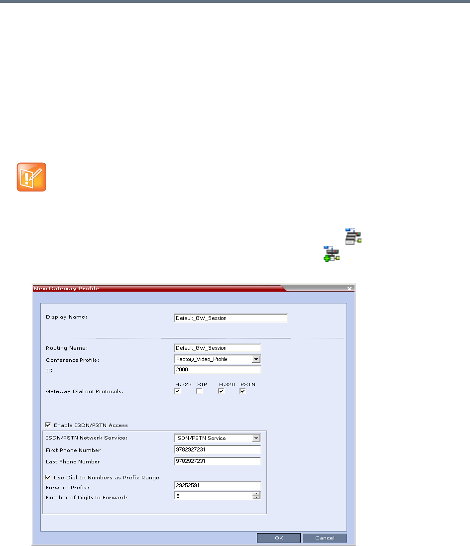
Gateway Calls
Polycom®, Inc. 638
Defining the Gateway Profile
A Gateway Profile is a conferencing entity, based on the Conference Profile assigned to it, that enables
endpoints to dial-in and initiate Gateway Sessions. The system is shipped with a default Gateway Profile,
named Default_GW_Session.
When an endpoint calls the Gateway Profile, a new Gateway Session is automatically created based on the
Profile parameters, and the endpoint joins the gateway call which can also be a multipoint conference if
more than two participants are connected to the conference.
The Gateway Profile defines the parameters of the gateway call that are taken from the Conference Profile
assigned to it, such as line rate, resolution, the IVR Service to be used and the dial-in numbers.
To define a new Gateway Profile:
1In the RMX Management - Rarely Used pane, click Gateway Profiles .
2In the Gateway Profiles list pane, click the New Gateway Profile button.
The New Gateway Profile dialog box opens.
Up to 1000 Gateway Profiles, Entry Queues, IP Factories and Meeting Rooms can be defined in the
Collaboration Server (they are all part of one repository whose size is 1000 entries).

Gateway Calls
Polycom®, Inc. 639
The new Gateway Profile is added to the list.
System Configuration
For details about adding and modifying system flags, see .
Displaying the Connection Information
You can hide the connection indications displayed on the participant’s screen during the connection phase
by changing the system configuration and manually adding and setting the system flag
DISABLE_GW_OVERLAY_INDICATION to YES in the MCMS_PARAMETERS_USER tab.
By default, this flag is set to NO and all connection indications are displayed.
Enabling PSTN dial-in using GK prefix
The feature is enabled when setting the flag USE_GK_PREFIX_FOR_PSTN_CALLS to Yes.
For more details, see PSTN Dial-in Using GK Prefix.
Gateway Calls Redialing
The Gateway can redial to numbers that are wrong, or busy or there is no answer.
Gateway Redial Guidelines
●Redial with IVR is supported:
In CP environments only.
For H.323, SIP and ISDN calls.
When using the Collaboration Server’s Inviting Participants using DTMF functionality.
●Redial with IVR is not supported:
When using PCM’s Invite Participant functionality.
Dialing multiple destination numbers.
Redial on Wrong Number
An IVR message is played requesting the user to enter a new number, followed by up to five redial attempts.
If all redial attempts fail, the user is alerted by an IVR message that the dialed number is unreachable,
followed by reorder tone and disconnection.
Do not enable PSTN/ISDN access without defining the dial-in numbers range and/or the use of
“Dial-In Numbers as Prefix Range”. If you enable the PSTN/ISDN access without the definition of the
dialing parameters, people can dial in to the gateway from outside the organization and then make
long distance calls at the 'host' expense.
Gateway Calls
Polycom®, Inc. 640
Wrong Destination Number
●The number of re-dial attempts is controlled by the WRONG_NUMBER_DIAL_RETRIES system
flag.
The default number of redial attempts is 3. To modify the number of redial attempts, manually add the
flag to system.cfg and set its value to the number of redial attempts required.
The flag value range is 0-5. A flag value of 0 means that no redials are attempted.
For more information about system flags see .
●Redial attempts follow the same order as defined in the Gateway Profile: H.323, followed by SIP,
followed by ISDN. For more information about Gateway Profiles and Gateway Dial out Protocols see
Defining the Gateway Profile.
●Redial on Wrong Number is activated if a Gateway Call fails, for all defined protocols, for any reason
or combination of reasons listed in the following table.
The user receives the Redial on Wrong Number IVR message: Incorrect destination.
Please enter the destination number.
If all the redial attempts fail the user receives the Disconnect on Wrong Number IVR message:
Destination could not be reached; call is disconnected.
●Gateway Re-dial is not activated if the reason for call failure is Busy or No Answer, for any of the
defined protocols.
Wrong Destination Number Time-out
●A time-out counter is started when the Redial on Wrong Number message is played. If the user does
not enter another destination number within the time-out period it is considered a failed dial out
attempt.
●The Redial on Wrong Number message and time-out are repeated according to the value of the
WRONG_NUMBER_DIAL_RETRIES system flag. If there is no input from the user, after completing
the retries, the user receives the Disconnect on Wrong Number IVR message: Incorrect
destination number followed by the Reorder Tone.
Call Failure Reasons - H.323, SIP, ISDN
H.323 SIP ISDN
Unreachable Destination 484 - Address Incomplete 3 - No Route to Destination
Bad Format Address 404 - Not Found 18 - No User Responding
Adaptive Busy 414 - Request-URI Too Long 28 - Invalid Number Format
Admission Rejected (ARJ)
Reason: Request Denied
Item 1: Cannot find
location.
416 - Unsupported URI Scheme 41 - Temporary Failure
Admission Rejected (ARJ)
Reason: Called Party Not
Registered
420 - Bad Extension
421 - Extension Required
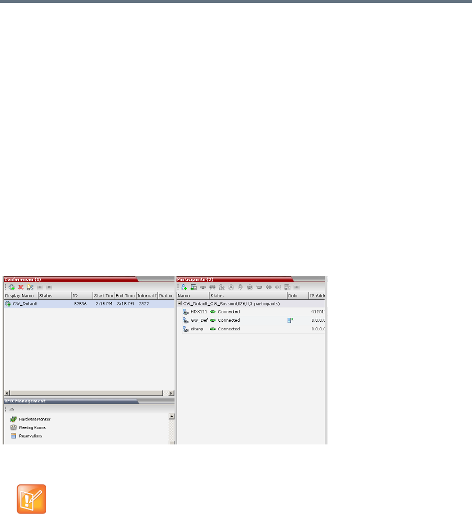
Gateway Calls
Polycom®, Inc. 641
Disconnect on Busy
Redialing of calls to busy destination can be selected. The number of redial attempts is dependent on the
NUMBER_OF_REDIAL system flag, the default value is 3.
If all redialing retry attempts fail, the user receives the Disconnect on Busy message in the form of Busy
Tone. The call is then disconnected.
Disconnect on No Answer
If all retry attempts fail, the user receives the Disconnect on No Answer message in the form of Reorder
Tone. The call is then disconnected.
Disconnect on Wrong Number
If a call fails due to no answer at the destination, the user receives the Disconnect on Wrong Number IVR
message: Incorrect Destination Number followed by Reorder Tone. The call is then disconnected.
Monitoring Ongoing Gateway Sessions
Ongoing Gateway Sessions that are created when calling the Gateway Profile, are listed in the ongoing
Conferences list pane.
Gateway Sessions are monitored in the same way as the conferences. For more details on monitoring
conferences, see Conference Level Monitoring.
Connection Indications
During the connection process to the other endpoints, the system displays on the calling participant’s screen
the called number and the connection status.
A Maximum of 32 characters can be displayed for connection indications. If the displayed information is
longer than 32 characters the text is truncated.
Additional ISDN and PSTN Participants cannot dial in directly to the Gateway Session once it was
started.

Gateway Calls
Polycom®, Inc. 642
If the system dials out to only one destination endpoint, the dialed number is not shown, only the connection
status.
If the destination endpoint is ISDN, the system displays the connection progress in percentages, where the
percentages represent various stages in the connection process as follows:
●Up to 60% the connection of the ISDN channels (up to 30 channels can be connected when E1 is
used for the connection).
●60% - 80% BONDING stage.
●80% - 90% Capability exchange stage.
●90% - 99% Media connection stage.
Once the call is completed, the indications are cleared.
If the call is not completed after trying all possible protocols, the system displays the number that was dialed
on the calling endpoint’s screen and one of the following causes:
●Busy - The far endpoint is in another call. In such a case, the system does not try to connect using
another communication protocol.
●Rejected - The far endpoint has rejected the call. In such a case, the system will try to connect using
another communication protocol.
●Unreached - The number could not be resolved by the gatekeeper or the SIP proxy or could not be
found on the network. In such a case, the system will try to connect using another communication
protocol.
●Failed - Any reason causing the system not to complete the connection process. In such a case, the
system will try to connect using another communication protocol.
You can hide the connection indications by changing the system configuration. For more details, see System
Configuration.
Gateway Session Parameters
The Collaboration Server creates a new conference that acts as a Gateway Session.
Gateway Session Name
The Gateway Session has a unique ID whose display name is composed of the following components:
●The prefix GW_,
●The Gateway Profile display name. For example, Default_GW_Session
●(number) where the number is a gateway conference counter.
For example: if the Gateway Profile display name is Default_GW_Session, the conference name will be
GW_Default_GW_Session(001).
Conference ID
The ID of the new conference is assigned randomly by the MCU.
The Gateway Session automatically ends when only one participant is left in the session.

Gateway Calls
Polycom®, Inc. 643
Connected Participant Parameters
Once this conference is created, the calling participant is connected to it and one or several dial-out
participant(s) are automatically created and added to this gateway session. The dial-in participant is also
identified as the chairperson of the conference.
The connecting (dial-in) participant name is taken from the endpoint. If the endpoint does not send its name,
it is derived from the Gateway Profile display name and it includes the Gateway Session name, underscore
and a random number is displayed (between brackets), for example,
GW_Default_GW_Session(001)_(000).
The name of the destination (dial-out) participant is taken from the endpoint. If the endpoint does not send
its name, it is taken from the dialed number. If the dialed number was an IP address, the system displays
underscores instead of dots, for example, 172_22_172_89.
Participants connected to a gateway session are monitored in the same way as participants connected to
ongoing conferences. For details, see Participant Level Monitoring.
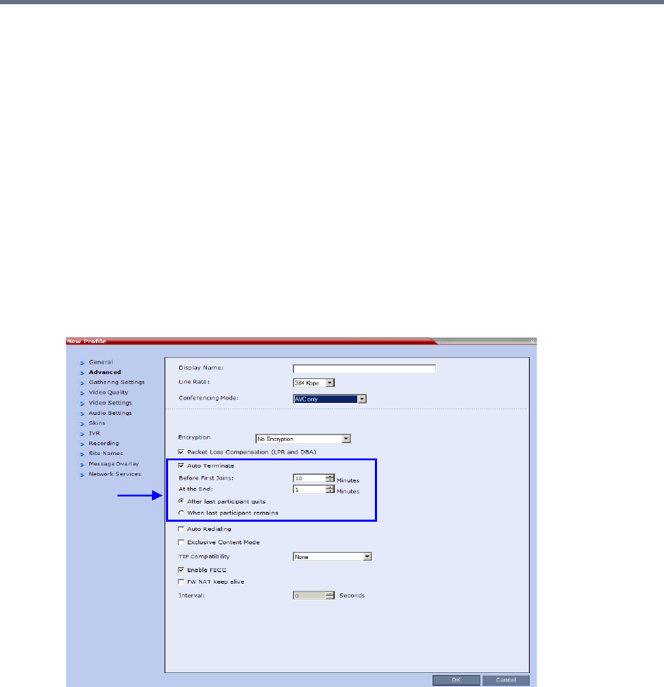
Gateway Calls
Polycom®, Inc. 644
Direct Dialing from ISDN/PSTN Endpoint to IP Endpoint
via a Meeting Room
Dialing from an ISDN endpoint to a specific IP endpoint using the Gateway Profile is a two-step process
(dialing to the Gateway and then entering the number of the destination IP endpoint).
When dialing to specific IP endpoints you can simplify the dialing process by creating the appropriate
Meeting Room.
To set up the Meeting Room for direct dialing in:
1Set the conference parameters in the Conference Profile and make sure that the conference will
automatically end when there is only one participant connected to the meeting.
2Define the Meeting Room with the following:
Conference Profile in which the Auto Terminate - At the end - When Last Participant Remains
option is selected. For more details on Conference Profile definition, see Defining the IVR Service
for Gateway Calls.
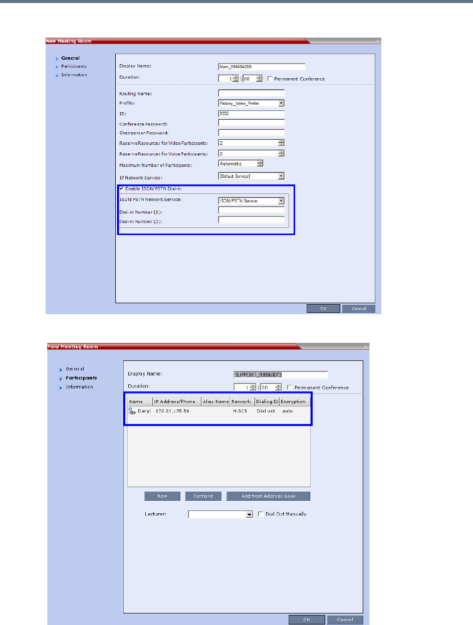
Gateway Calls
Polycom®, Inc. 645
▪ISDN/PSTN access is enabled and a dial-in number is assigned to the Meeting Room.
The dial-out IP endpoint is added to the Meeting Room’s Participants list.
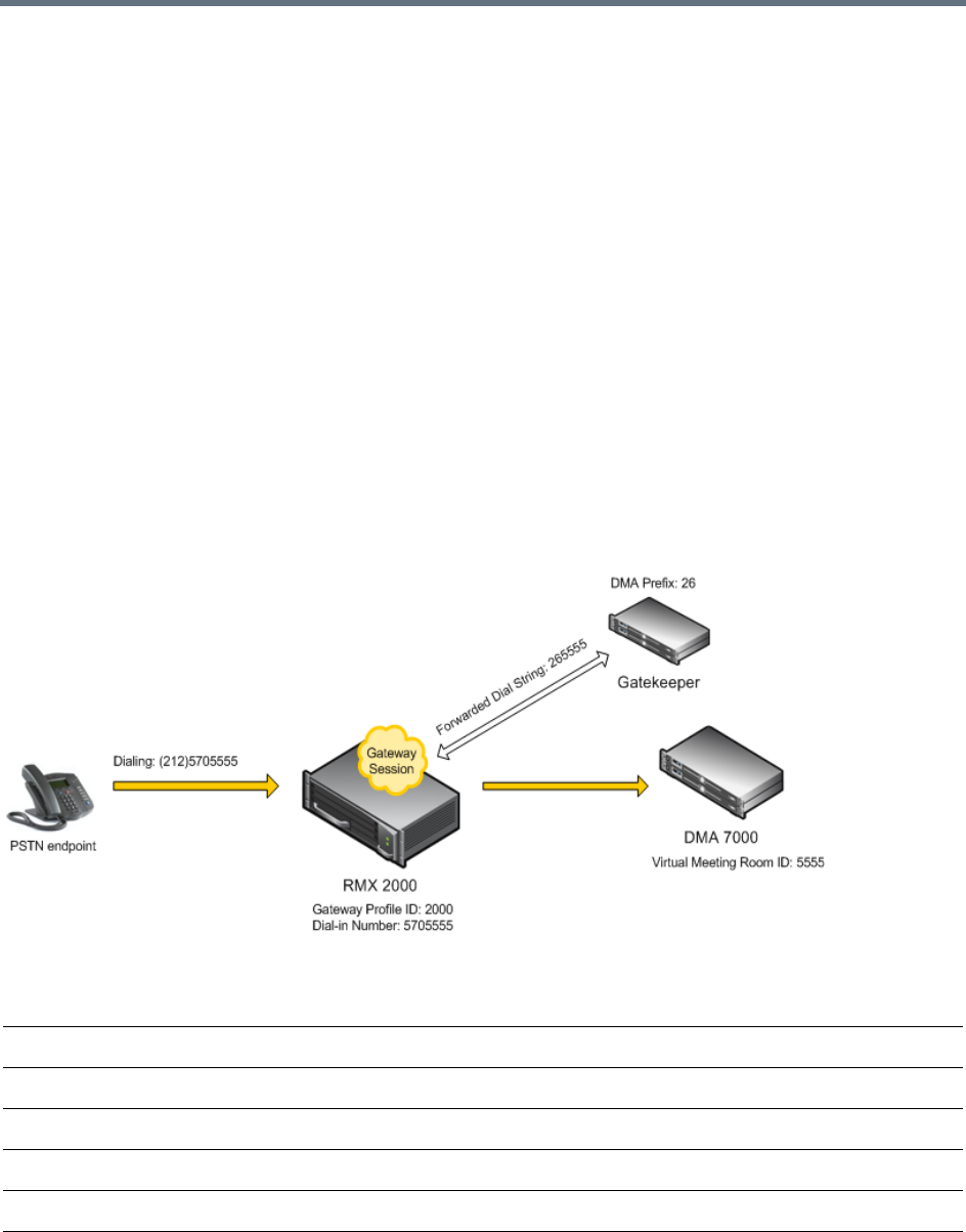
Gateway Calls
Polycom®, Inc. 646
Dialing to Polycom® RealPresence DMA System
Two dialing methods are available to ISDN/PSTN participants calling the DMA:
●Direct with automatically generated destination dial strings from dial-in strings. This option is
available only to Collaboration Servers with MPMx cards.
●Via Gateway IVR.
In addition, PSTN participants can dial the Gateway IVR and can use the MCU or DMA prefix in the
gatekeeper together with the conference ID/endpoint alias as the destination string to simplify the input. This
is one of the methods for PSTN participants to connect to a virtual Meeting Room on the DMA. For more
details, see PSTN Dial-in Using GK Prefix.
Calling a RealPresence DMA Direct with Automatically Generated
Destination Dial Strings
In this configuration, the gateway session initiator enters one of the dial-in numbers assigned to the gateway
profile. This number is truncated by the Collaboration Server gateway and the truncated digits are replaced
by a prefix that corresponds either to the DMA prefix in the Gatekeeper.
Call Flow from ISDN Endpoint to Polycom DMA with Automatically Generated Forwarded Dial String
Example:
The figure above shows the call flow assuming the following parameters:
First Dial-in Number 5705550
Last Dial-in Number 5705560
Use Dial-in Numbers as Destination ID Selected
DMA Meeting Room ID 5555
Destination Prefix (DMA prefix in Gatekeeper) 26
Number of Rightmost Digits to Append 4

Gateway Calls
Polycom®, Inc. 647
Calling the RealPresence DMA via Gateway IVR
Audio PSTN/ISDN calls can be routed to Polycom DMA 7000 via the Collaboration Server. ISDN Video
endpoints connect using their audio channels (but consume video resources). The RealPresence DMA
system enables load balancing and the distribution of multipoint calls on up to 10 Polycom Collaboration
Server media servers.
As part of this solution, the Collaboration Server acts as a gateway for the DMA that supports H.323 calls.
The PSTN or ISDN endpoint dials the virtual Meeting Room on the DMA via the Gateway Profile on the
Collaboration Server.
Both the Collaboration Server and the RealPresence DMA must be registered with the same gatekeeper.
The dialing string of the destination conference on the RealPresence DMA must be communicated to the
dialing endpoint and used during the connection to the Gateway Profile on the Collaboration Server. There
are two options available for doing this:
●Manual Dial String Entry
●Automatic Dial String Generation
Manual Dial String Entry
Dialing String and Call Flow from ISDN Endpoint to Polycom DMA
The connection is done in two steps:
●A PSTN/ISDN participant dials the dial-in number assigned to the Gateway Profile (5705555),
including the country and area code (if needed) and connects to the Gateway IVR.
●When prompted for the target conference ID, the caller enters the string of the target meeting room
on the DMA followed by the # key.
PSTN participant dials (212)5705555
Number that will be used by Collaboration Server to forward the call to the DMA 265555
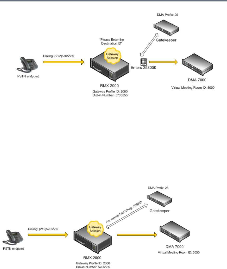
Gateway Calls
Polycom®, Inc. 648
This string is composed of the RealPresence DMA prefix as registered in the gatekeeper and the ID
of the virtual meeting room running on the RealPresence DMA. For example, if the DMA prefix is 25
and the target meeting room ID is 8000 the participant enters 258000 followed by the # key.
The Collaboration Server creates a Gateway Session with two participants, the calling participant and
the link to the conference running on the RealPresence DMA.
Automatic Dial String Generation
The administrator can configure the Gateway Profile to automatically generate and forward the dial string
from the Collaboration Server Gateway Session to the RealPresence DMA in order to connect to the
required RealPresence DMA Meeting Room. When this configuration option is selected, the participant
does not need to interact with the IVR Service.
Call Flow from ISDN Endpoint to RealPresence DMA with Automatically Generated Forwarded Dial String

Gateway Calls
Polycom®, Inc. 649
Example:
The figure above shows the call flow assuming the following parameters:
PSTN Dial-in Using GK Prefix
When connecting to an Collaboration Server that is standalone or part of a DMA solution deployment, PSTN
participants are prompted by an IVR message requesting the Destination Conference ID followed by the #
key to be entered using the DTMF input keypad.
Including the Gatekeeper Prefix in the DTMF input string enables PSTN participants to use the input string
when connecting to an Collaboration Server whether the Collaboration Server is a standalone MCU or part
of a DMA solution deployment.
Enabling PSTN dial-in using GK prefix
The feature is enabled by the USE_GK_PREFIX_FOR_PSTN_CALLS system flag in system.cfg. For more
information see Modifying System Flags.
The following table summarizes the PSTN participant’s DTMF input depending on the flag value.
First Dial-in Number 5705550
Last Dial-in Number 5705560
Use Dial-in Numbers as Destination ID Selected
DMA Meeting Room ID 5555
Destination Prefix (DMA Gatekeeper) 26
Number of Rightmost Digits to Append 4
PSTN participant dials (212)5705555
PSTN Participant input via DTMF
Configuration
FLAG: USE_GK_PREFIX_FOR_PSTN_CALLS=
NO YES
Standalone Collaboration Server
Conference ID= 1234
PSTN participant enters:
1234#.
PSTN participant enters:
761234#
(The Gatekeeper Prefix”76” is
automatically removed from
the DTMF input string for a
standalone Collaboration
Server.)
Collaboration Server with DMA
Virtual Meeting Room ID in DMA =
1234
DMA gatekeeper prefix = 76
PSTN participant enters:
761234#

Gateway Calls
Polycom®, Inc. 650
Deploying a Polycom RMX™ Serial Gateway S4GW
UC APL Public Key Infrastructure (PKI) requires that the Serial Gateway S4GW be connected directly to the
Collaboration Server and not to the H.323 network. The Serial Gateway effectively becomes an additional
module of the Collaboration Server, with all web and H.323 traffic passing through the Collaboration Server.
For more information see Deploying a Polycom RMX™ Serial Gateway S4GW in the RealPresence
Collaboration Server (RMX)1500/2000/4000 Deployment Guide for Maximum Security Environments.

Polycom®, Inc. 651
RMX Manager Application
The RMX Manager is the Windows version of the Collaboration Server Web Client. It can be used instead
of the Collaboration Server Web Client for routine Collaboration Server management and for Collaboration
Server management via a modem connection. For more information on using the RMX Manager via a
modem connection, see Appendix G - Configuring Direct Connections to the Collaboration Server.
.
Using the RMX Manager application, a single user can control a single or multiple MCU units as well as
conferences from multiple MCUs. The RealPresence Collaboration Server systems can be managed and
controlled by the RMX Manager application.
The RMX Manager can list and monitor:
●Up to 20 Collaboration Server systems in the MCUs pane
●Up to 800 conferences in the Conferences pane
●Up to 1600 participants in the Participants pane
The RMX Manager is faster than the RMX Web Client and can give added efficiency to Collaboration Server
management tasks, especially when deployed on workstations affected by:
●Lack of performance due to bandwidth constraints within the LAN/WAN environment.
●Slow operation and disconnections that can be caused by the anti-phishing component of various
antivirus applications.
The RMX Manager application can be installed in your local workstation or accessed directly on the
RealPresence Collaboration Server system without installing it in your workstation.
Installing the RMX Manager Application
The installation of the RMX Manager Application includes two main stages:
●Accessing or downloading the RMX Manager Installer
●Installing the RMX Manager application
For Maximum Security Environments, the RMX Manager is the recommended option for accessing
the RMX's management console. The RMX Manager specific to the Maximum Security version being
deployed can be downloaded from the Support section of the Polycom website.
Modem connection is not supported when the Collaboration Server is in Ultra Secure Mode. For
more information see Ultra Secure Mode.
Users with Auditor authorization level cannot connect to the RealPresence Collaboration Server via
the RMX Manager application and must use the RMX Web Client.
For information about Installing the RMX Manager for Secure Communication Mode see Download
and Install the RMX Manager Onto a Workstation in the RealPresence Collaboration Server (RMX)
1500/1800/2000/4000 Deployment Guide for Maximum Security Environments.

RMX Manager Application
Polycom®, Inc. 652
Guidelines
●The Collaboration Server Installation and First Entry Configuration must be completed before
installing the RMX Manager application.
For more details, see the Polycom RealPresence Collaboration Server (RMX) 1500/1800/2000/4000
Getting Started Guide.
●When upgrading the RMX Manager application, it is recommended to backup the MCU list using the
Export RMX Manager Configuration option.
For more details, see Import/Export RMX Manager Configuration.
●When upgrading the RMX Manager from a major version (for example, version 8.7.0) to a
maintenance version of that version (for example, 8.7.0.x), the installation must be performed from
the same MCU (IP address) from which the major version was installed.
●If you are upgrading from another MCU (different IP address), you must first uninstall the RMX
Manager application from the Windows Control Panel.
Accessing or Downloading the RMX Manager Installer
The RMX Manager installer can be downloaded or accessed and installed on your workstations using one
of the following methods:
●Accessing the RMX Manager Application Installer Directly from the MCU
●Downloading the RMX Manager application from the Polycom web site at
http://www.polycom.com/support and installing it. The Installation procedure is the same as if you
have downloaded the application from the Login screen.
●Accessing the RMX Manager Installer from the Login screen
Accessing the RMX Manager Application Installer Directly from the MCU
1Start Internet Explorer and in your browser enter:
http://<Collaboration Server IP Address>/RMXManager.html.
For example, if the Collaboration Server IP address is 10.226.10.46, enter in the browser the
following address: http://10.226.10.46/RMXManager.html.
The RMX Manager installation page is displayed.
The RMX manager can be installed for use by multiple users on a shared workstation. For more
information, see Installing the RMX Manager for Multi-User Capability.
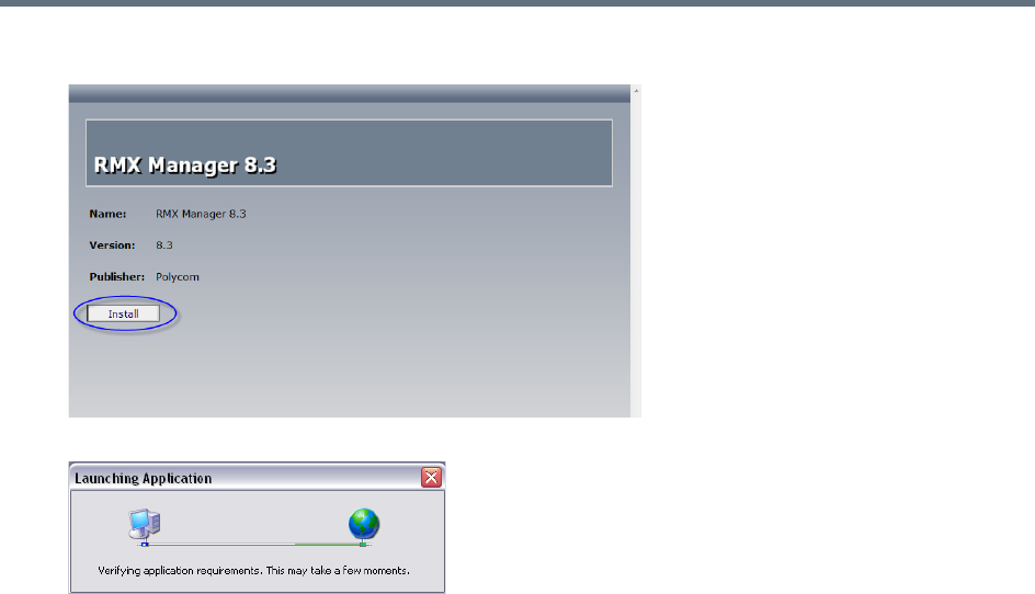
RMX Manager Application
Polycom®, Inc. 653
2Click Install.
The installer verifies the application’s requirements on the workstation.
3Continue the Installation as described in Installing the RMX Manager on Your Workstation.
Downloading the Installation files from Polycom Support Site
1Access the Polycom web site at http://www.polycom.com/support.
2Click on Documents and Downloads and then select UC Infrastructure from the drop-down list
3Select the appropriate RMX/Collaboration Server product.
4Click the RMX 1500/1800/2000/4000 version n.n.n.n Local Web Client (RMX Manager) link.
The file download dialog box opens.
5Follow the standard download procedure to either run the installer directly by selecting Open or
Save in the File Download dialog.
If you select Open, the download is performed and the archive containing the RMX Manager and
its components are saved in Internet Explorer’s Temporary Internet Files folder.
aNavigate to the RMX_x-x-x-nnnn_LocalWebClient-RMXManager >
RmxManagerInstallerMsi folder.
bDouble-click setup.exe to install the RMX Manager.
If you select Save, you need to specify where the archive containing the RMX Manager and its
components are saved locally.
aWhen the download completes, select Open or Open Folder.
bNavigate to the RMX_x-x-x-x_LocalWebClient-RMXManager folder.
cDouble-click deploy.application to install the RMX Manager.
6Continue the Installation as described in Installing the RMX Manager on Your Workstation.
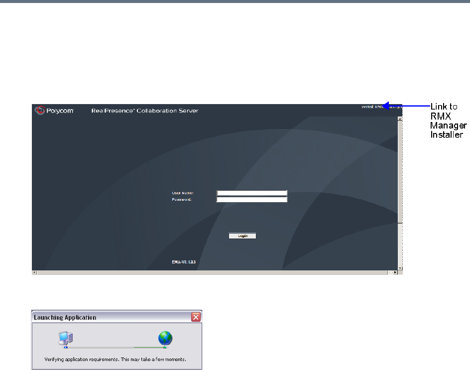
RMX Manager Application
Polycom®, Inc. 654
Accessing the RMX Manager Installer from the Login screen
1Start Internet Explorer and connect to one of the Collaboration Server units in your site. It is
recommended to connect to the Collaboration Server installed with the latest software version.
The Login screen is displayed.
There is a link to the RMX Manager Installer at the top of the right edge of the screen.
2Click the Install RMX Manager link.
The installer verifies the application’s requirements on the workstation.
The Install dialog box is displayed.
Installing the RMX Manager on Your Workstation
Once the installer has verified that the application’s requirements on the workstation are met, the The Install
dialog box is displayed.
1Click the Install button.
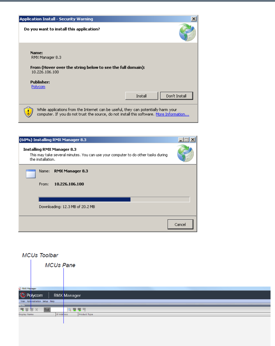
RMX Manager Application
Polycom®, Inc. 655
The installation proceeds.
The installation completes, the application loads and the RMX Manager - MCUs screen is displayed.
The first time you start the RMX Manager application, the MCUs pane is empty.
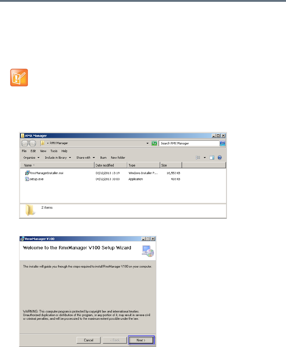
RMX Manager Application
Polycom®, Inc. 656
Installing the RMX Manager for Multi-User Capability
The RMX Manager can be installed to be available to all users of a shared computer during the initial
installation.
The following procedure is performed after downloading the RMX Manager from the Polycom Support
website.
To install the RMX Manager for Multiple Users:
1Download the RMX Manager installation package from the Polycom Support website.
2Unzip the installation package.
3Double-click setup.exe to open the RMX Manager Setup Wizard.
The RMX Manager can still be installed from the Collaboration Server Web Client, but the installation
will only be available to the current user.
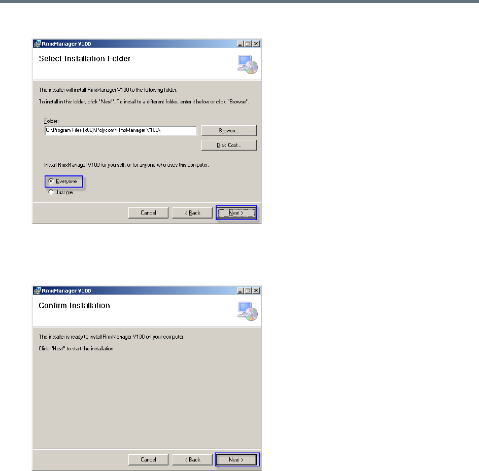
RMX Manager Application
Polycom®, Inc. 657
4Click Next.
5Select Everyone to install the RMX Manager for all users sharing the computer.
(Select Just me to install the RMX Manager just for the current user.)
6Click Next.
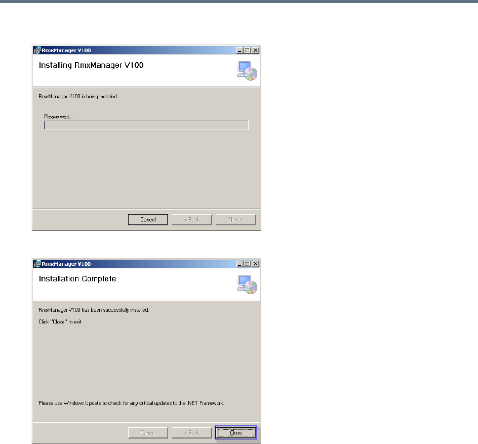
RMX Manager Application
Polycom®, Inc. 658
The installation begins.
When the installation is complete, a confirmation window is displayed.
7Click Close to close the RMX Manager installer.
The installation is complete.
Starting the RMX Manager Application
Once installed, the RMX Manager can be run using the http:// (non-secured) or https:// (secured)
command in the browser’s address line or the Windows Start menu.
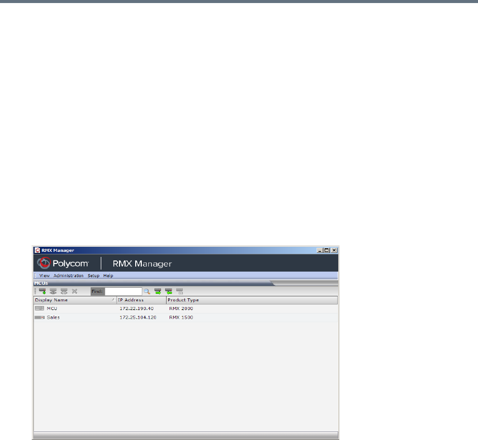
RMX Manager Application
Polycom®, Inc. 659
To use the browser:
1In the browser’s command line, enter:
http://<MCU Control Unit IP Address>/RMXManager.html
or
https://<MCU Control Unit IP Address>/RMXManager.html
2Press Enter.
To use the Windows Start menu:
1Click Start > Programs.
aIf the RMX Manager is displayed in the recently used programs list, click RMX Manager in the list
to start the application.
or
bClick All Programs > Polycom > RMX Manager.
The MCUs screen is displayed, listing the MCUs currently defined in the RMX Manager.
This screen enables you to add additional MCUs or connect to any of the MCUs listed. For details on
adding MCUs, see Adding MCUs to the MCUs List.
For each listed MCU, the system displays the following information:
MCU Display Name (as defined in the Add MCU dialog box).
IP Address of the MCU’s control unit
Product Type - The MCU type: RealPresence Collaboration Server (RMX)
1500/1800/2000/4000.
Before connecting to the MCU for the first time, the Collaboration Server type is unknown so RMX
is displayed instead as a general indication.
To display the RMX Manager main screen you must connect to one of the listed Collaboration
Servers. For more details, see Connecting to the MCU.
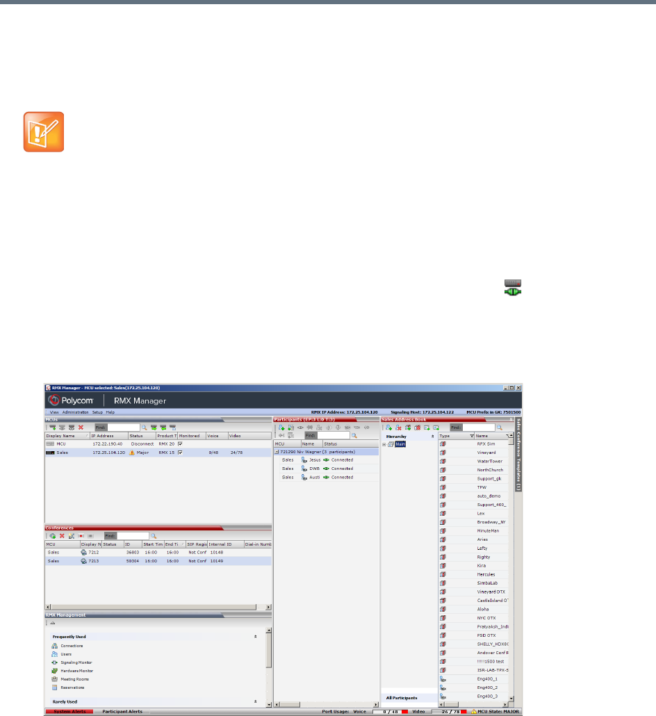
RMX Manager Application
Polycom®, Inc. 660
Connecting to the MCU
Once an MCU is defined, the RMX Manager can be connected to it. This allows you to set up conferences,
make reservations, monitor On Going Conferences and perform other activities on several MCUs.
To connect the RMX Manager to an MCU:
1In the MCUs pane or screen, use one of the following methods:
aDouble-click the MCU icon.
bSelect the Collaboration Server to connect and click the Connect MCU button.
cRight-click the MCU icon and then click Connect MCU.
If you are connecting to the MCU from the MCUs opening screen and have defined the Username
and Password for the connecting MCU, the system connects to the Collaboration Server, and the
RMX Manager Main Screen is displayed.
If you are connecting to any MCU from the MCUs pane in the RMX Manager Main Screen and have
defined the Username and Password for the connecting MCU, the MCU icon changes to connected
and its status, type and number of audio and video resources are displayed in the MCUs pane.
If the Username and Password are missing from the MCU parameters, or if the Remember Me check
box has been cleared, the Connect dialog box opens.
2Enter the Username and Password of the user with which you will login to the MCU.
The first Collaboration Server unit that is connected to the RMX Manager dictates the Authorization
Level of Users that can connect to the other MCUs on the list. For example, if the Authorization level of
the User POLYCOM is Administrator, all Users connecting to the other MCUs on the list must be
Administrators. Each user can have a different login name and password for each of the listed MCUs
and they must be defined in the Users list of each of the listed MCUs.
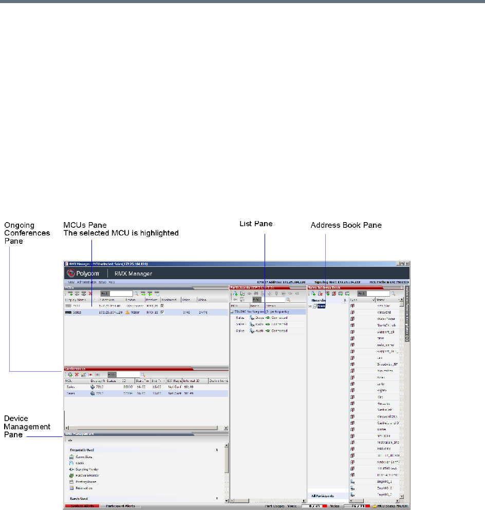
RMX Manager Application
Polycom®, Inc. 661
3To add the user name and password to the MCU properties so you will not have to enter them each
time you login to the MCU, make sure that the Remember Login check box is selected. Otherwise,
clear the Remember Login check box.
4Click OK.
The system connects to the Collaboration Server, and the RMX Manager Main Screen is displayed.
If a User with the entered Username and Password is not defined in the Collaboration Server, an error
message is displayed and the system lets you re-enter the Username and Password.
RMX Manager Main Screen
The RMX Manager Main Screen is displayed only when at least one MCU is connected.
This screen is similar to the RMX Web Client Main Screen with the addition of the MCUs pane. As in the
RMX Web Client, the panes are displayed according to the Authorization Level of the logged in User. The
MCUs pane is displayed to all users.
Only one MCU can be selected in the MCUs pane. If only one MCU is connected, it is automatically
selected. The selected MCU is highlighted.
The menu items, the Collaboration Server Management features, the Address Book and the Conference
Templates are all properties of the selected MCU and apply to it.
MCUs Pane
The MCUs pane includes a list of MCUs and a toolbar.
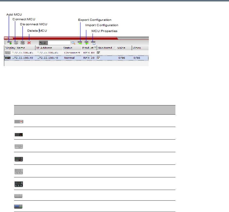
RMX Manager Application
Polycom®, Inc. 662
For each listed MCU, the system displays the following information:
●MCU Display Name - the name of the MCU and its icon according to its type and connection status.
The following icons are available:
MCU Icons and Statuses
●IP Address - of the MCU’s control unit.
●Status - The status of the MCU:
Connected - the MCU is connected to the RMX Manager and can be managed by the RMX
Manager user.
Disconnected - The MCU is disconnected from the RMX Manager
Major - The MCU has a major problem. MCU behavior could be affected and attention is required.
●Product Type - The MCU type: RealPresence Collaboration Server 1500/1800/2000/4000. Before
connecting to the MCU for the first time, the Collaboration Server type is unknown so RMX is
displayed instead as a general indication.
●Monitored - When checked indicates that the conferences running on this MCU are automatically
added to the Conferences list and monitored. To stop monitoring the conferences running on this
MCU and their participants, clear the Monitored check box.
Icon Description
RealPresence Collaboration Server (RMX) 1500, disconnected.
RealPresence Collaboration Server (RMX) 1500, connected.
RealPresence Collaboration Server (RMX) 2000, disconnected.
RealPresence Collaboration Server (RMX) 2000, connected.
RealPresence Collaboration Server (RMX) 4000, disconnected.
RealPresence Collaboration Server (RMX) 4000, connected.
RealPresence Collaboration Server 1800, disconnected
RealPresence Collaboration Server 1800, connected

RMX Manager Application
Polycom®, Inc. 663
●Video Resources - The number of video resources that are available for conferencing.
●Audio Resources - The number of audio resources that are available for conferencing (applicable
to Collaboration Server 1500/2000/4000 in MPMx Card Configuration Mode only).
Use Other RMX Manager UI Components
The RMX Manager has all the UI components that a RMX web client has, together with a unique MCU list
pane.
For more information on other UI components, such as conference pane, address book and so on, refer to
Collaboration Server Web Client Screen Components.
You can always control and manage conferences using either the RMX manager or the RMX web client.
Operations described throughout this book apply to both the RMX manager and the RMX web client.
Adding MCUs to the MCUs List
The RMX Manager can connect to one or several Collaboration Servers simultaneously. If the site’s
configuration includes more than one MCU, or when a new MCU is added to your configuration, and you
want to monitor and control all MCUs from within the same window, you must add the MCU to the MCUs list.
To add the MCU to the list of MCUs being managed, define the MCU’s connection parameters.
To add a Collaboration Server unit:
1On the MCUs toolbar, click Add MCU to add an MCU to the MCU list.
The Add MCU dialog box opens.
The Collaboration Server must be installed and its IP addresses properly configured in the
Management Network Service before defining its connection parameters in the RMX Manager
application.
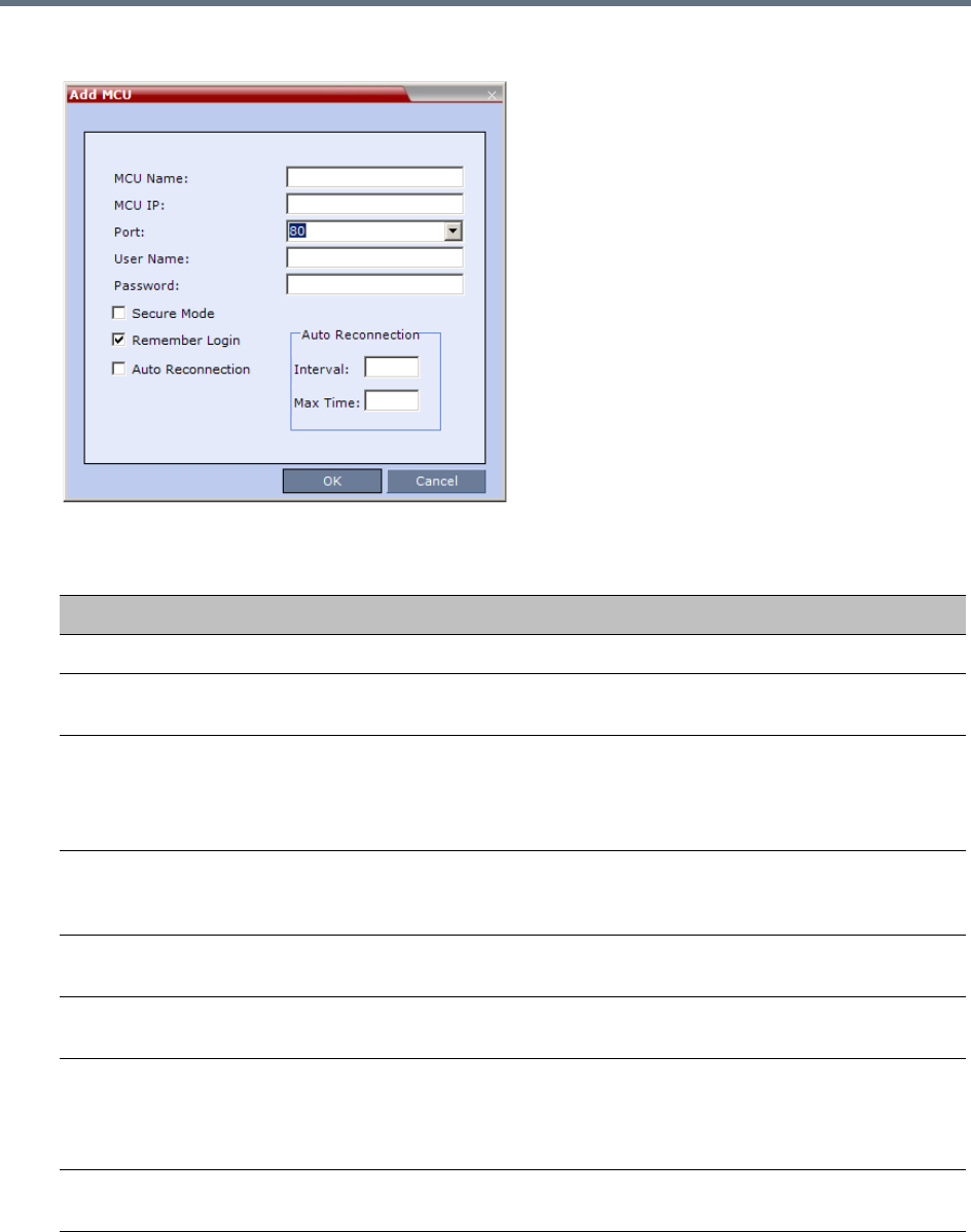
RMX Manager Application
Polycom®, Inc. 664
2Define the following parameters:
MCU Properties
Field Description
MCU Name Enter the name of the MCU on the network.
MCU IP Enter the IP address of the MCU’s Control Unit. The IP address must be identical to the
one configured in the MCU during first entry Configuration.
Port Enter the number of the port used for communication and data transactions between
the Collaboration Server unit and the RMX Manager.
For standard connection, enter 80.
For a Secured connection (using TLS or SSL), enter 443.
Username Enter the user name with which you will login to the MCU. A User with this name must
be defined in the Collaboration Server Users list. The system is shipped with a default
User whose name is POLYCOM.
Password Enter the password as defined for the user name with which you will login to the MCU.
The system is shipped with a default User whose password is POLYCOM.
Secure Mode Optional. Select this check box to connect to the Collaboration Server with SSL and
work in Secure Mode.
Remember Login This check box is automatically selected, and it enables the usage of the user name
and password entered in this dialog box when connecting to the Collaboration Server.
If this check box is cleared, the user is prompted for the user name and password when
connecting to this Collaboration Server unit.
Auto
Reconnection
Select this check box to automatically reconnect to the Collaboration Server if the
connection between the RMX Manager and the MCU is broken.
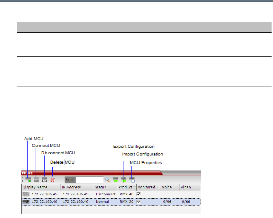
RMX Manager Application
Polycom®, Inc. 665
3Click OK.
The MCU is added to the MCUs pane.
4If required, repeat steps 1-3 to define additional Collaboration Server units.
The MCUs pane contains the list of all defined MCUs.
Grouping the Participants by MCU
The Participants can be grouped by MCU and then by conferences.
To change the display mode for the Participants pane:
Interval Enter time in seconds between reconnect ion attempts to the Collaboration Server. For
example, if you enter 10, the system will wait 10 seconds between the connection
attempts.
Max Time Enter the maximum amount of time in seconds that the Collaboration Server is allowed
to try to reconnect. If the Collaboration Server reconnects before the allotted time frame
the count down timer is halted. For example, if you enter 100, the system will stop trying
to reconnect if it has failed to do so within 100 seconds.
MCU Properties
Field Description
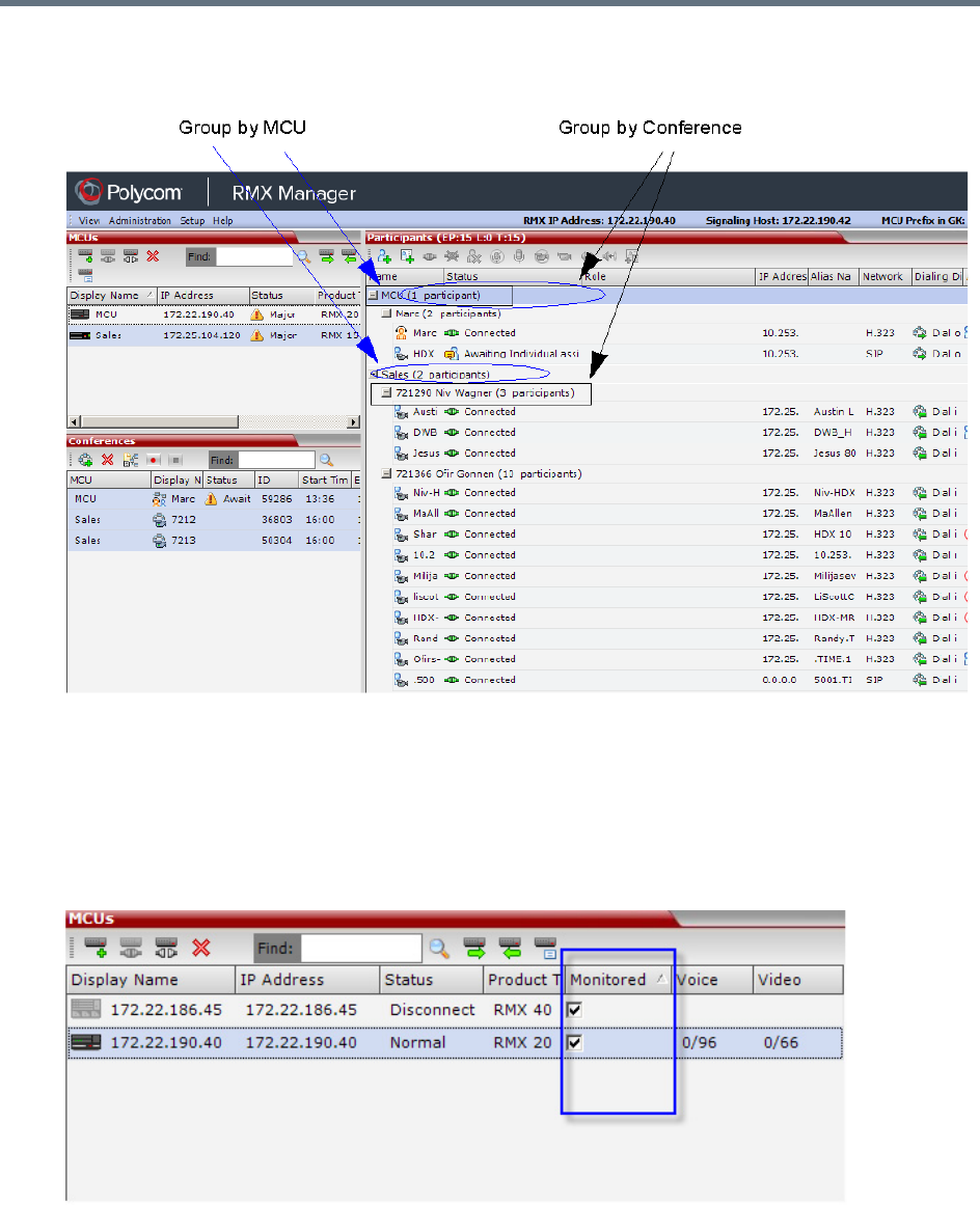
RMX Manager Application
Polycom®, Inc. 666
●On the Collaboration Server menu, click View > Group by MCU.
The Participants pane display changes accordingly.
To toggle between the two display modes, click View > Group by MCU.
Start Monitoring/Stop Monitoring
By default, all conferences running on connected Collaboration Servers are monitored.
You can stop the automatic monitoring of conferences on a specific MCU in one of the following methods:
»By clearing the check box in the Monitored column in the MCUs pane.
Right-clicking the MCU icon and selecting Stop Monitoring.
The check box is cleared in the Monitored column.

RMX Manager Application
Polycom®, Inc. 667
»To start monitoring again, click the check box in the Monitored column in the MCUs pane, or
right-clicking the MCU icon and selecting Start Monitoring.
Modifying the MCU Properties
You can view the currently defined MCU settings, and modify them when required, for example, change the
MCU name, IP address or Secured mode.
Use this procedure to add the Username and Password to the properties of the MCU that was
automatically added to the MCU list when installing the RMX Manager. This enables automatic login when
connecting the MCU to the RMX Manager.
You can modify the MCU properties when the MCU is connected or disconnected.
To view and/or modify the MCU Properties:
1Use one of the following methods:
aSelect the MCU to disconnect and click MCU Properties .
bRight-click the MCU icon and then click MCU Properties.
The MCU Properties dialog box opens.
2Define/modify the required parameters. For details, see MCU Properties.
3Click OK.
Disconnecting an MCU
An MCU can be disconnected from the RMX Manager, without removing it from the MCUs list.
To disconnect an MCU:
1Use one of the following methods:
aSelect the MCU to disconnect and click Disconnect MCU .
bRight-click the MCU icon and then click Disconnect MCU.
The MCU icon changes to disconnected and any ongoing conference running on that MCU will not
be monitored in this RMX Manager; they are removed from the Conferences pane. This MCU can
still be monitored and controlled by other users.
Removing an MCU from the MCUs Pane
An MCU can be removed from the RMX Manager. This function should be used if the MCU hardware was
disconnected and removed from the network.
To Remove an MCU from the list:
1Use one of the following methods:
aSelect the MCU to disconnect and click Delete .
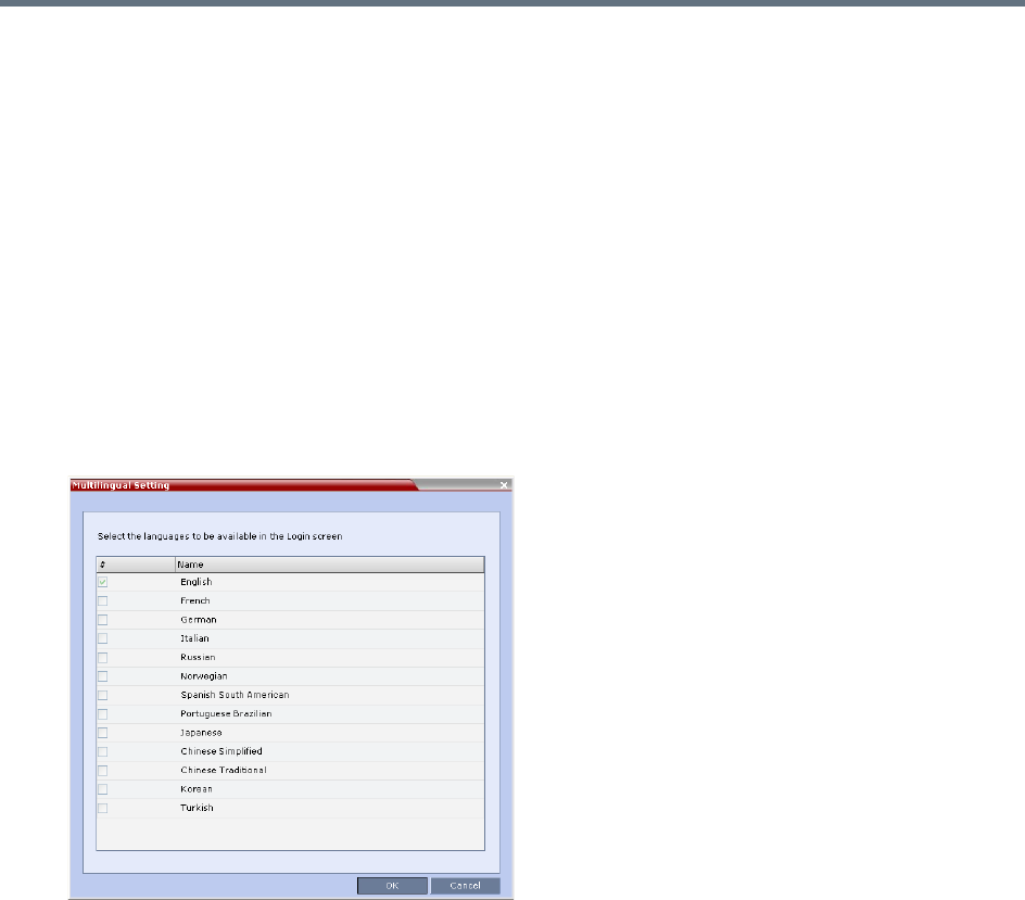
RMX Manager Application
Polycom®, Inc. 668
bRight-click the MCU icon and then click Remove MCU.
A confirmation message is displayed.
2Click OK to confirm or Cancel to abort the operation.
The MCU icon is removed from the MCUs pane.
Changing the RMX Manager Language
You can change the language of the RMX Manager menus and dialog boxes. Only one language can be
selected at a time and the RMX Manager application must be restarted after changing the display language.
To select a language:
1On the RMX Manager menu, click Setup > Customize Display Settings > Multilingual Settings.
The Multilingual Settings dialog box opens, displaying the current language selection.
2Click the check box of the required language. Only one language can be selected.
3Click OK.
4Restart the RMX Manager application to implement the language change.
Import/Export RMX Manager Configuration
The RMX Manager configuration that includes the MCU list and the multilingual selection can be save to
any workstation/PC on the network and imported to any Multi-RMX Manager installed in the network. This
enables the creation of the MCUs list once and distributing it to all RMX Manager installations on the
network.
In addition, when upgrading to a previous version, the MCU list is deleted, and can be imported after
upgrade.
The exported file is save in XML format and can be edited in any text editor that can open XML files.
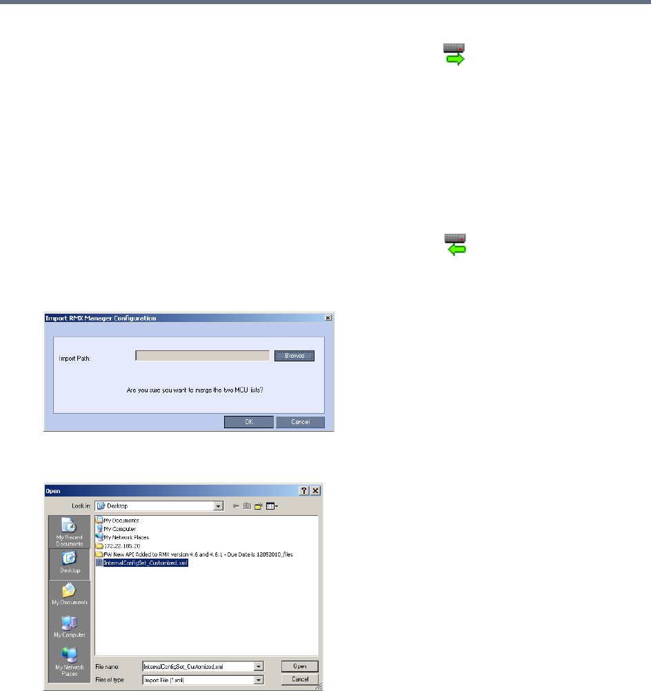
RMX Manager Application
Polycom®, Inc. 669
To Export the RMX Manager Configuration:
1In the RMX Manager, click Export RMX Manager Configuration in the toolbar, or right-click
anywhere in the MCUs pane and then click Export RMX Manager Configuration.
The Export RMX Manager Configuration dialog box opens.
2Click Browse to select the location of the save file, or enter the required path in the Export Path
box.
The selected file path is displayed in the Export Path box.
3Click OK to export the RMX Manager configuration.
To Import the RMX Manager Configuration:
1In the RMX Manager, click Import RMX Manager Configuration in the toolbar, or right-click
anywhere in the MCUs pane and then click Import RMX Manager Configuration.
The Import RMX Manager Configuration dialog box opens.
2Click the Browse button to select the saved file, or enter the required path in the Export Path box.
The Open dialog box is displayed.
3Select the XML file previously saved, and click the Open button.
The selected file path is displayed in the Import Path box.
4Click OK to import the file.
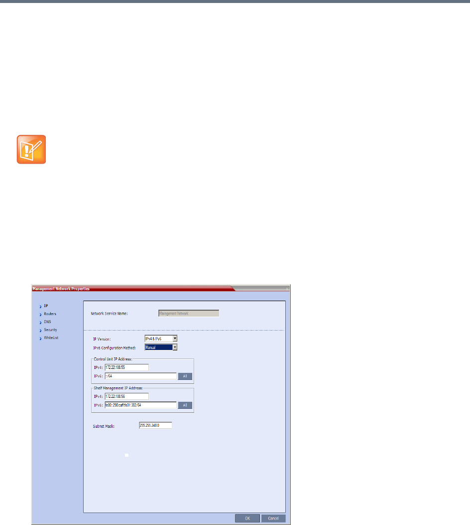
RMX Manager Application
Polycom®, Inc. 670
Installing RMX Manager in Secure Communication
Mode
The RMX Manager cannot be downloaded from an MCU operating in Secure Communication Mode, without
a valid TLS certificate.
The following procedure describes how to obtain a TLS certificate and download the RMX Manager from
the MCU operating in Secure Communication Mode.
To install the RMX Manager:
1Set the Collaboration Server to Non Secure Communication Mode
aIn the RMX Management pane, click IP Network Services.
bIn the IP Network Services list pane, double click the Management Network entry.
The Management Network Properties dialog box is displayed.
FIPS is always enabled in Ultra Secure Mode, and when ClickOnce is used to install RMX Manager,
the workstation must have one of the following installed:
•.NET Framework 3.5 or a later version of the .NET Framework.
•.NET Framework 2.0 plus Service Pack 1 or later.
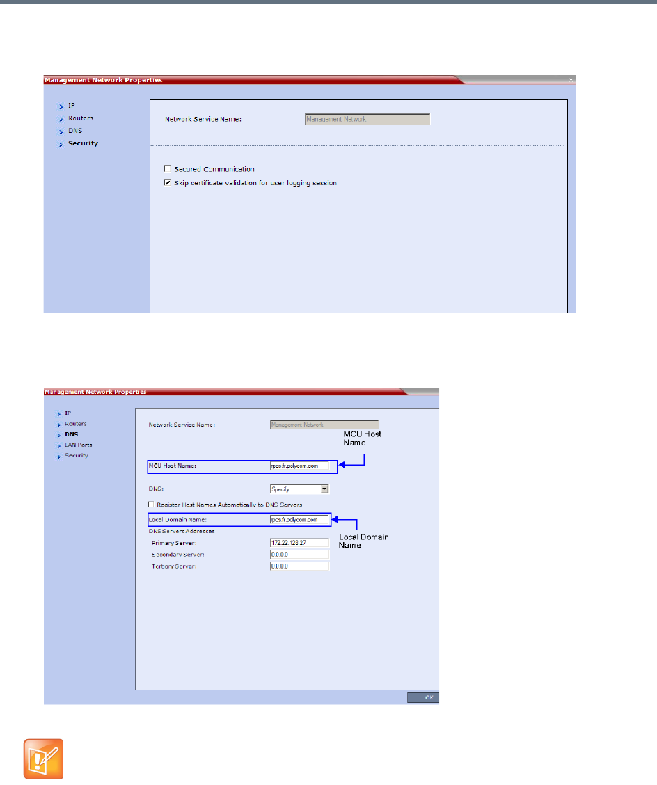
RMX Manager Application
Polycom®, Inc. 671
cClick on the Security tab.
The Security dialog box is displayed.
dClear the Secured Communication check box.
2Click the DNS tab.
The DNS dialog box is displayed.
3Enter the Local Domain Name.
The Local Domain Name must be the same as the MCU Host Name. If the content of these two fields
are not identical an active alarm is created.
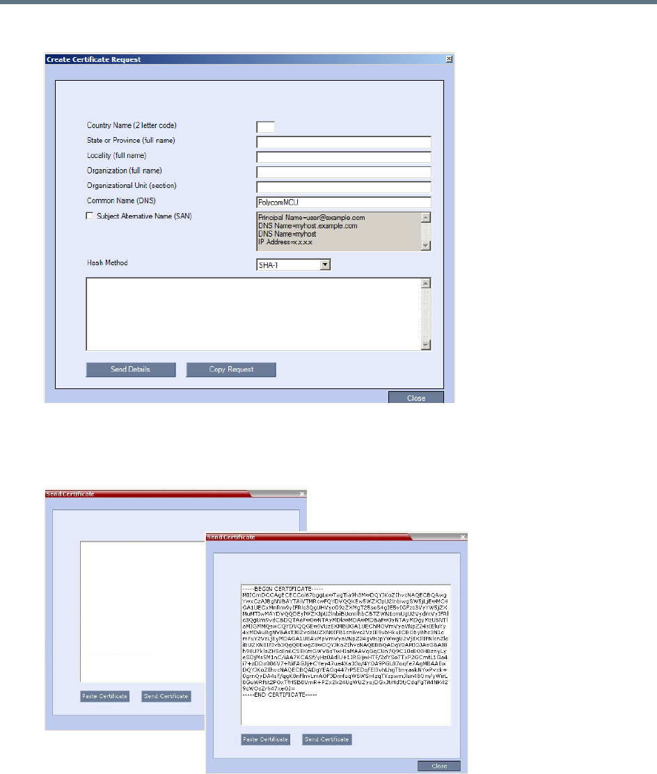
RMX Manager Application
Polycom®, Inc. 672
4Create a Certificate Request.
For more information, see Purchasing and Installing a Certificate.
Certificates can also be created and issued using an Internal Certificate Authority. For more
information see Using an Internal Certificate Authority.
5Install the certificate.
For more information, see Purchasing and Installing a Certificate.
6Set the Collaboration Server to Secure Communication Mode
aIn the RMX Management pane, click IP Network Services.
bIn the IP Network Services list pane, double click the Management Network entry.
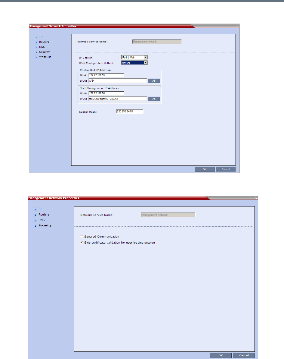
RMX Manager Application
Polycom®, Inc. 673
The Management Network Properties dialog box is displayed.
cClick the Security tab.
The Security dialog box is displayed.
dSelect the Secured Communication check box.
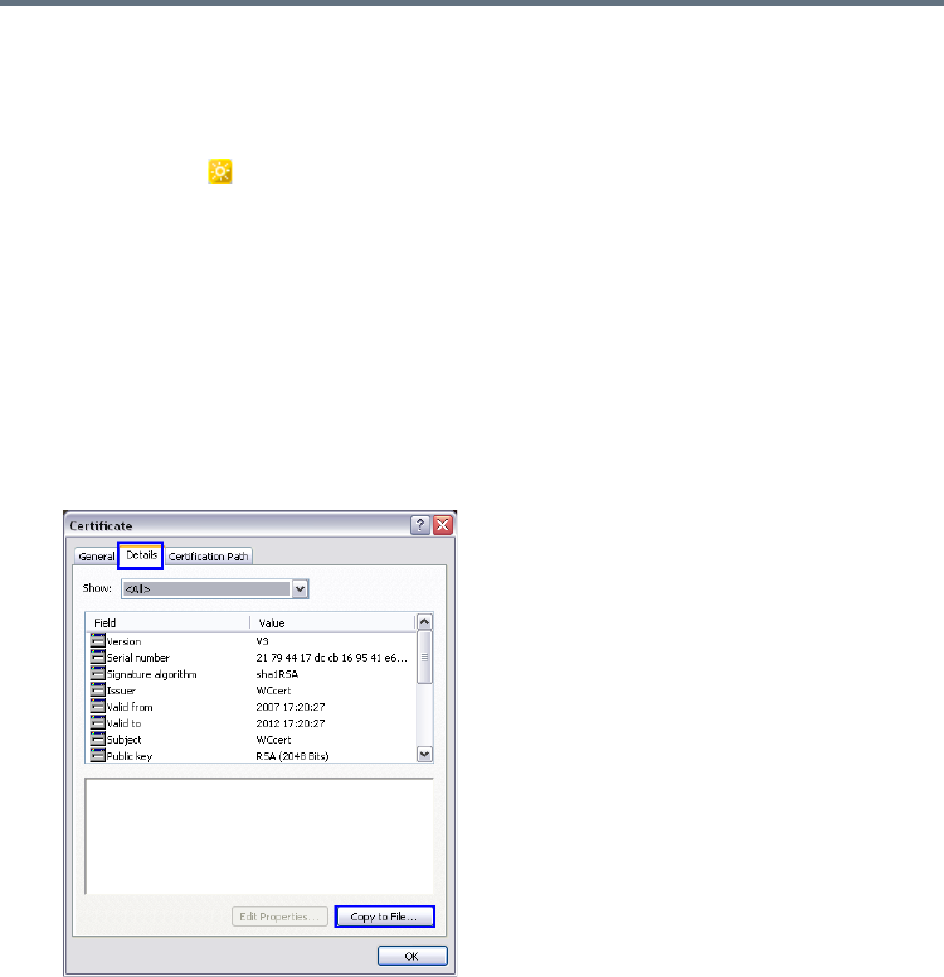
RMX Manager Application
Polycom®, Inc. 674
eClick OK.
7Reset the Collaboration Server:
aIn the RMX Management pane, click Hardware Monitor .
The Hardware Monitor pane is displayed.
bClick Reset ().
8Install the RMX Manager. For more information see Installing the RMX Manager Application.
Using an Internal Certificate Authority
If your TLS certificate was created and issued by an Internal Certificate Authority, it may not be seen as
having been issued by a trusted Certificate Authority. The RMX Manager is not downloaded successfully
and a warning is received stating that the certificate was not issued by a trusted Certificate Authority.
To add the Internal Certificate Authority as a trusted Certificate Authority:
1Navigate to the folder where the certificate (.cer) file is saved.
2Open the certificate file.
3Click the Details tab.

RMX Manager Application
Polycom®, Inc. 675
4Click the Copy to File button.
The Certificate Export Wizard is displayed.
5Click Next.
The Export File Format dialog box is displayed.
6Select Base-64 encoded X.509 (.CER).
7Click Next.
The File to Export dialog box is displayed.
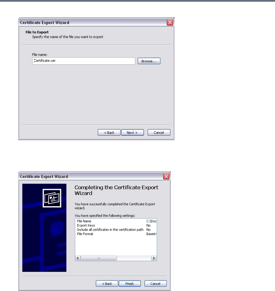
RMX Manager Application
Polycom®, Inc. 676
8In the File Name field, enter the file name for the exported certificate.
9Click Next.
The final Certificate Export Wizard dialog box is displayed.
10 Click Finish.
The successful export message is displayed.
11 Click OK.

Polycom®, Inc. 677
Use the RMX Web Client
You can manage or monitor a Polycom RealPresence Collaboration Server with the RMX Web Client
application, using Internet Explorer installed on your workstation, or using RMX Manager application.
The RMX Manager is the Windows version of the RMX Web Client. For more information, see RMX
Manager Application.
Starting the RMX Web Client
You start the RMX Web Client by connecting to the MCU system. To connect to the MCU you need to get
the following information from your system administrator:
●User name
●Password
●MCU Control Unit IP Address
You can always control and manage conferences using either the RMX manager or the
RMX web client. Operations described throughout this book apply to both the RMX
manager and the RMX web client.
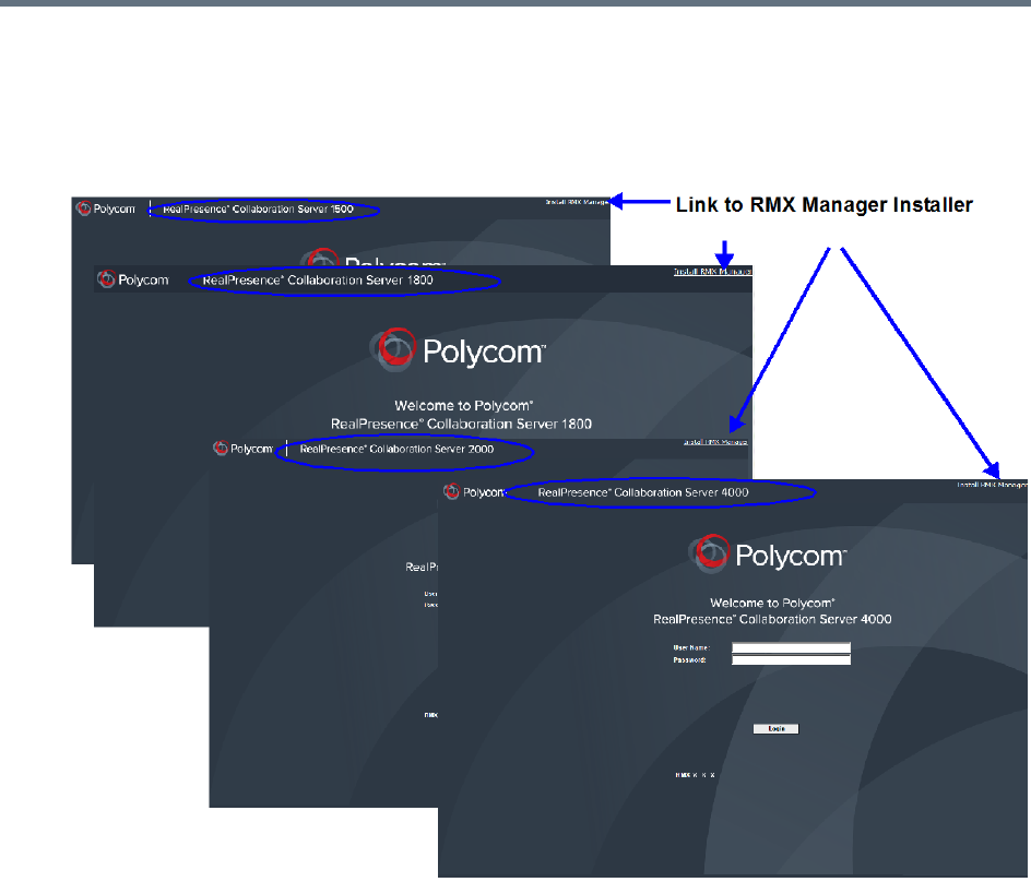
Use the RMX Web Client
Polycom®, Inc. 678
To start the Collaboration Server Web Client:
1In your browser address line, enter http://<Control Unit IP Address> and press the Enter
key.
The Login screen is displayed.
2Enter your User Name and Password and click the Login button.
If the default User name and password were not changed on first entry, the default user name and
password are both POLYCOM.
The RMX Web Client main screen is displayed.
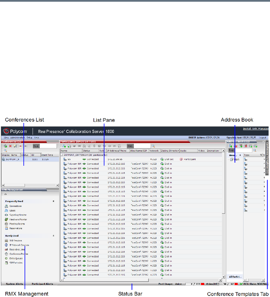
Use the RMX Web Client
Polycom®, Inc. 679
RMX Web Client Screen Components
The RMX Web Client main screen consists of the following panes:
●Conference List
●Status Bar
●List Pane
●Address Book
●Collaboration Server Management
●Conference Templates Tab
You can login as a user with Chairperson, Operator or Administrator authorization. Your Authorization Level
determines your viewing and system functions.
The Administrator’s view is shown below.
The main screen can be customized. For more information, see Customizing the Main Screen.
Viewing and System Functionality Permissions
Your User’s Authorization Level determines the viewing and system functionality of the RMX Web Client as
summarized in the following table.
Use the RMX Web Client
Polycom®, Inc. 680
For more information on users and permissions, see
Collaboration Server Users
.
Viewing and System Permissions
Authorization Level
Chairperson Operator Administrator
Viewing Permissions
Conference List
List pane
Address Book pane
Conference Templates pane
Status Bar
RealPresence Collaboration Server Management pane
Conference Alarms
Conference Status
Configurations dialog boxes
System Functionality
Start Conferences
Monitor Conferences
Monitor Participants
Solve Basic Problems
Modify MCU Configuration
In addition to Chairpersons, Operators and Administrators, additional user types are:
•Auditor: A user that can view Auditor Files and audit the system. For more information, see
Auditor
.
• Machine Account: A User Name associated with servers (machines). For more information, see
Machine Account
.
• Administrator - Read Only: A user with the viewing and monitoring permissions of a regular
Administrator, but can only create system backups and cannot perform any other functional
operation. For more information, see
Administrator Read-only
.
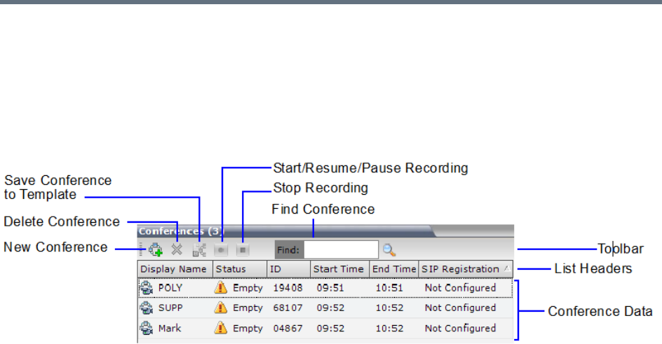
Use the RMX Web Client
Polycom®, Inc. 681
Conferences List
If you are logged in as a User with Operator or Administrator permissions:
The Conferences pane lists all the conferences currently running on the MCU along with their Status,
Conference ID, Start Time and End Time data. The number of ongoing conferences is displayed as the
title of the pane.
The Conferences List toolbar contains the following buttons:
●New Conference – Starts a new ongoing conference.
●Delete Conference – Deletes the selected conference(s).
●Save Conference to Template - Saves the conference with its participants to a template for future
use.
●If Conference Recording is enabled for AVC Only conferences, the following buttons are displayed in
color:
Start/Resume Recording – Starts/resumes recording.
A Recording Indication is displayed to all conference participants informing them that the
conference is being recorded.
Stop Recording – Stops recording.
Pause – Toggles with the Start/Resume button.
A Paused Indication is displayed to all conference participants informing them that conference
recording has been paused.
If you are logged in as a User with Chairperson permissions:
●You can list and monitor conferences you have started or for which you have entered the password
or that don’t have a Chairperson Password assigned.
●A Chairperson Password field and a Refresh button are displayed.
Enter a password and click Refresh to display a list of conferences with the requested password.
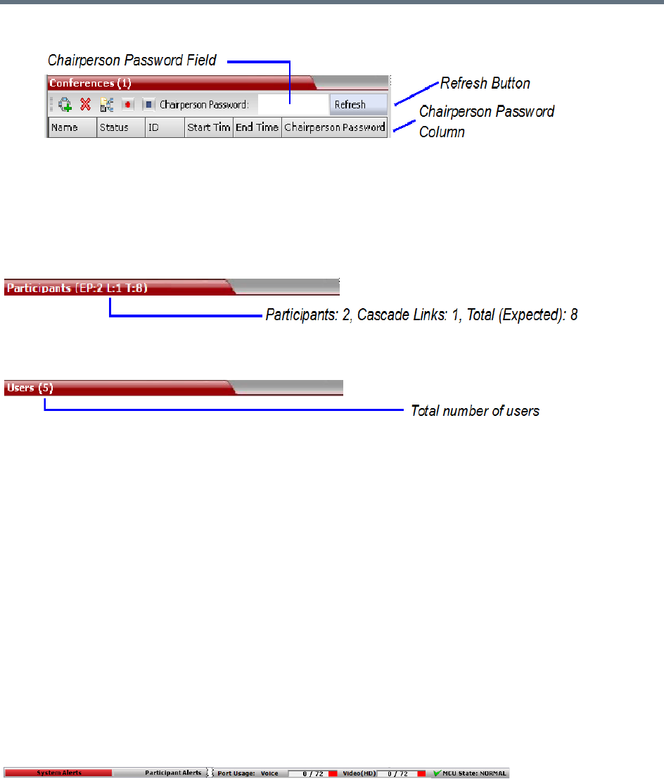
Use the RMX Web Client
Polycom®, Inc. 682
●A Chairperson Password column is included in the conference data.
List Pane
The List pane displays details of the item selected in the Conferences pane or RMX Management pane.
The title of the pane changes according to the selected item.
Example: When an ongoing conference is selected on the Conferences pane, the list and parameters of
the connected participants is displayed.
Selecting an item in the RMX Management pane lists the items currently defined.
Example: If the Users item is selected, a list of system Users defined for the MCU is displayed.
RMX Management Pane
This view is available to Operators and Administrators.
The RMX Management pane lists the entities that need to be configured to enable the Collaboration Server
to run conferences. Only users with Administrators permission can modify these parameters.
The RMX Management pane is divided into two sections:
●Frequently Used – Parameters often configured monitored or modified.
●Rarely Used – Parameters configured during initial system set-up and rarely modified afterward.
Items can be moved between these two sections to customize the management tasks per system User. For
more details, see Customizing the RMX Management Pane.
Status Bar
This view is available to Operators and Administrators.
The Status Bar at the bottom of the RMX Web Client contains System and Participant Alerts tabs as well as
Port Usage Gauges and an MCU State indicator. Information included in the status bar varies with the
product model.
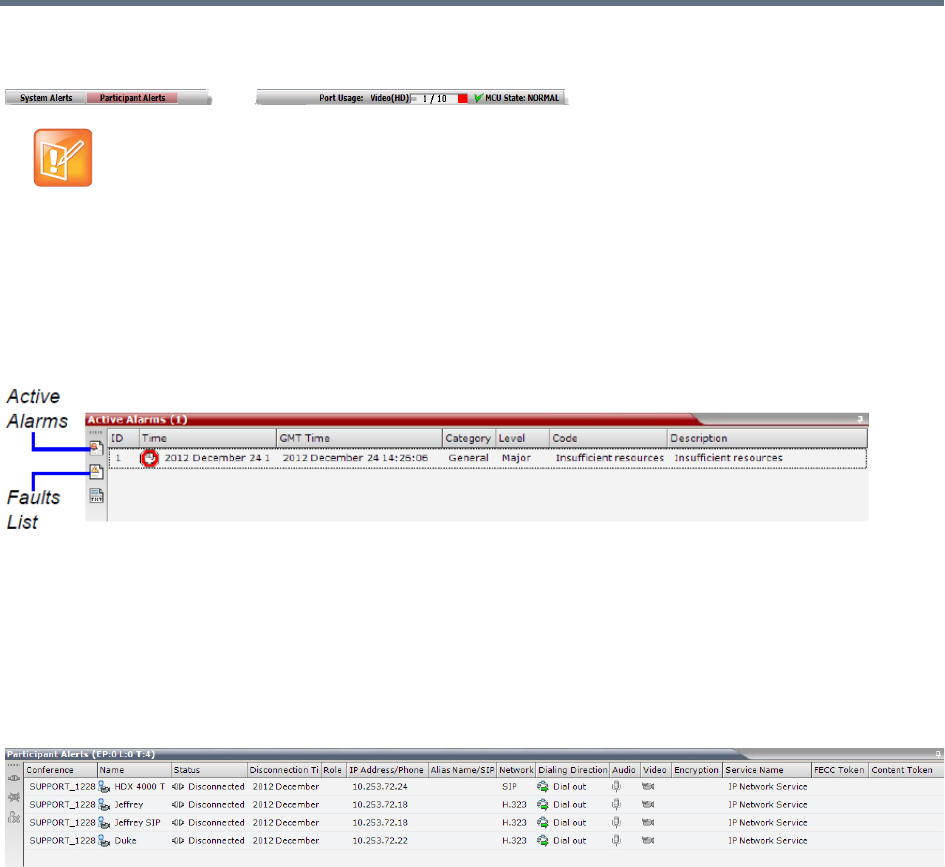
Use the RMX Web Client
Polycom®, Inc. 683
System Alerts
This view is available to Operators and Administrators.
This is a list of system problems. The alert indicator flashes red when at least one system alert is active.
The flashing continues until a user with Operator or Administrator permission reviews the list.
The System Alerts pane is opened and closed by clicking the System Alerts button in the left corner of the
Status Bar.
For more information about Active Alarms and Faults List, see
System and Participant Alerts
.
Participant Alerts
This view is available to Operators, Chairpersons and Administrators.
This is a list of participants that are experiencing connection problems. It is sorted by conference.
The Participant Alerts pane is opened and closed by clicking the Participant Alerts button in the left corner
of the Status Bar.
The basic unit used for reporting resource usage in the Port Gauges his HD720p30. Usage numbers
are rounded to the nearest integer.
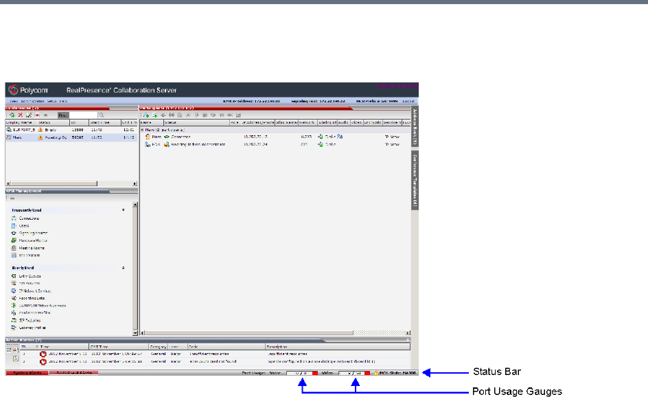
Use the RMX Web Client
Polycom®, Inc. 684
Port Usage Gauges
The Port Usage Gauges are displayed in the Status Bar at the bottom of the RMX Web Client screen.
In the RealPresence Collaboration Server (RMX) 1500/2000/4000, the Port Usage gauges displays for the
selected MCU:
●The total number of Video or Voice ports in the system according to the Video/Voice Port
Configuration. The Audio gauge is displayed only if Audio ports were allocated by the administrator,
otherwise only the Video port gauge is displayed.
●The number of Video and Voice ports in use.
●The High Port Usage threshold.
In the RealPresence Collaboration Server 1800 and the RealPresence Collaboration Server (RMX)
2000/4000 with an MPMRx card, the Port Usage Gauge displays for the selected MCU:
●The total number of Video ports in the system.
●The number of Video ports in use.
●The High Port Usage threshold.
Port Gauges - RealPresence Collaboration Server (RMX) 1500/2000/4000 with MPMx cards
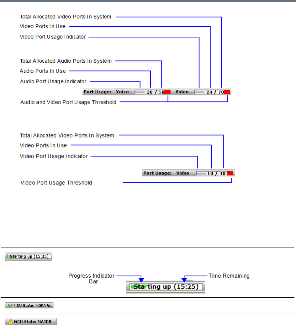
Use the RMX Web Client
Polycom®, Inc. 685
Port Gauges - RealPresence Collaboration Server 1800 and RealPresence Collaboration Server (RMX)
2000/4000 with MPMRx cards
The basic unit used for reporting resource usage in the Port Gauges is HD720p30. Results are rounded to
the nearest integer.
MCU State
This view is available to Chairpersons, Operators and Administrators.
The MCU State indicator displays one of the following:
Address Book
This view is available to Chairpersons, Operators and Administrators.
The Address Book is a list of Participants and Groups that have been defined on the MCU. The information
in the Address Book can be modified only by an administrator. All system users can, however, view and use
the Address Book to assign participants to conferences.
The MCU is starting up. The time remaining until the system start-up is complete is
displayed between brackets while a blue progress indicator bar indicates the start-up
progress.
The MCU is functioning normally.
The MCU has a major problem. MCU behavior could be affected and attention is required.
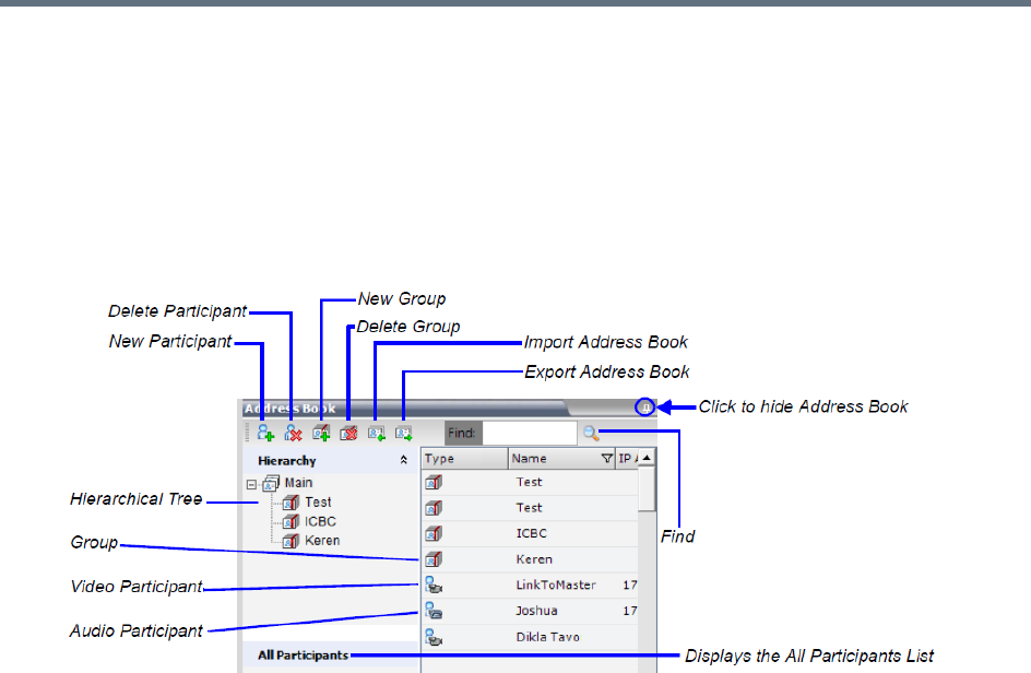
Use the RMX Web Client
Polycom®, Inc. 686
The Address Book toolbar contains a Quick Search field and the following six buttons:
●New Participant
●New Group
●Delete Participant
●Delete Group
●Import Address Book
●Export Address Book
The Navigation pane of the Address Book contains the following types of lists:
●Hierarchical — Displays a multi-level hierarchical tree of groups and participants. Double-clicking a
group on the navigation pane displays the group participants and sub-groups in the List pane.
●All Participants — Displays the single unique entity of all the participants in a single level as in
previous versions. When adding a participant to a group, the system adds a link to the participant’s
unique entity that is stored in the All Participants list.
The Participants List in the Address Book lists entries according to:
●Type – Indicates whether an individual Participant or a Group of participants
●Name – The name of the participant or group
●Dialing Direction – Dial-in or Dial-out
●IP Address/Phone – IP Address/Phone of the participant
●Encryption - Indicates whether the participant is encrypted, not encrypted or the system
automatically selects the encryption according to the conference settings
Displaying and Hiding the Address Book
The first time you access the RMX Web Client, the Address Book pane is displayed. You can hide it by
clicking the anchor pin button.
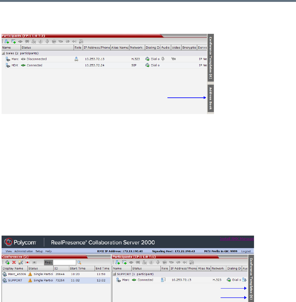
Use the RMX Web Client
Polycom®, Inc. 687
The Address Book pane closes and a tab appears at the right edge of the screen.
Click the tab to re-open the Address Book.
Conference Templates
Conference Templates enable administrators and operators to create, save, schedule and activate identical
conferences.
A Conference Template:
●Saves the conference Profile.
●Saves all participant parameters including their Personal Layout and Video Forcing settings.
●Simplifies the setting up Telepresence conferences where precise participant layout and video forcing
settings are crucial.
Displaying and Hiding Conference Templates
The Conference Templates list pane is initially displayed as a closed tab in the RMX Web Client main
window. The number of saved Conference Templates is indicated on the tab.
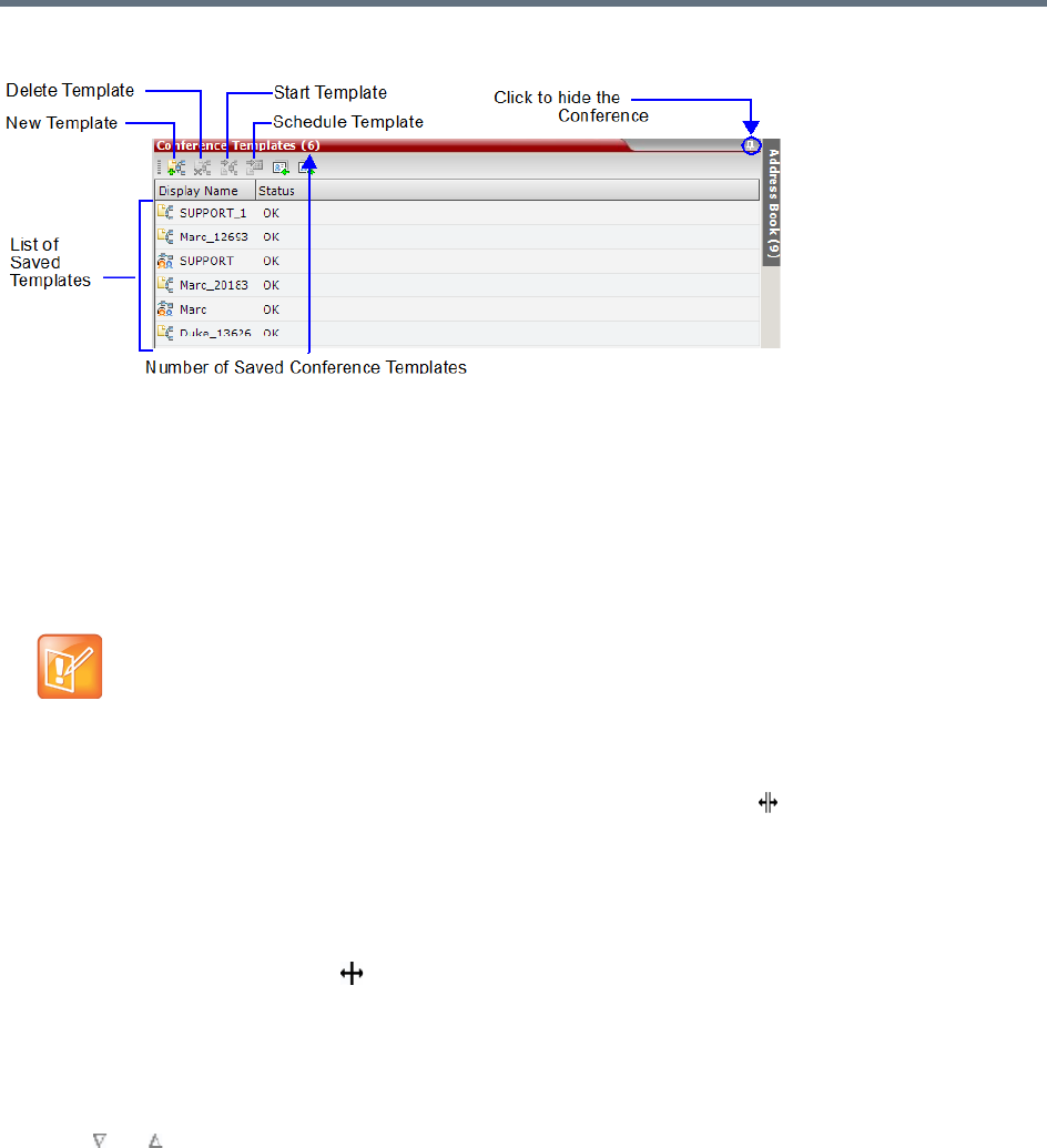
Use the RMX Web Client
Polycom®, Inc. 688
Clicking the tab opens the Conference Templates list pane.
Hide the Conference Templates list pane by clicking the anchor pin button in the top right corner of the
pane.
The Conference Templates list pane closes and a tab appears in the top right corner of the screen.
Customizing the Main Screen
You can customize the main screen according to your preferences. Pane sizes can be changed, column
widths can be adjusted and data lists can be sorted.
To resize a pane:
»Move the pointer over the pane border, and when the pointer becomes , resize the pane border to
the required size.
To adjust column width:
1In the column header row, place the pointer on the vertical field-separator bar of the column.
2When the pointer becomes , resize the field-separator bar to the required column size.
To sort the data by any field (column heading):
1In the Conference List or List view pane, click on the column heading of the field to be used for
sorting.
A or symbol appears in the column heading indicating that the list is sorted by this field, as well
as the sort order.
2Click on the column heading to toggle the column’s sort order.
To change the order of columns in a pane:
»Click the column heading to be moved and drag it to its new position, until a set of red arrows appears
indicating the column’s new position.
Customization settings are automatically saved for each logged-in user.
The next time the RMX Web Client is opened, the main screen settings appear as they were when
the user exited the application.
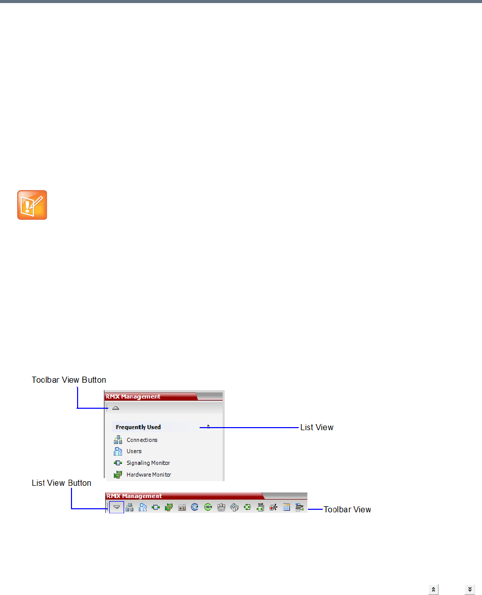
Use the RMX Web Client
Polycom®, Inc. 689
To restore the RealPresence Collaboration Server display window to its default
configuration:
»On the system menu, click View > Restore RMX Display Defaults.
Increasing and Decreasing the Text Size
You can increase or decrease the text size of the RMX Web Client windows for easier readability.
To increase or decrease the text size:
1On the system menu, click View.
2Select the Zoom option to achieve the desired text size percentage (default is 100%).
Customizing the RMX Management Pane
The RMX Management pane can be viewed either as a list or as a toolbar.
To switch between Toolbar and List Views:
1In the RMX Management pane, click the Toolbar View button to switch to Toolbar view.
2In Toolbar view, click the List View button to switch back to List view.
In List view, you can move items between the Frequently Used and Rarely Used sections
depending on the operations you most commonly perform and the way you prefer to work with the
RMX Web Client. This option does not work in Toolbar view as all items are represented by icons.
To expand or collapse the Frequently Used and Rarely Used sections:
The Frequently Used and Rarely Used sections can be expanded or collapsed by clicking the and
buttons.
In some cases, the text in the dialog boxes in the RMX Web Client might appear not aligned or
incomplete. This issue is not caused by setting the Zoom option. Rather, the text size in the Display
settings in Windows Control Panel may affect the display of the dialog boxes. Check the Windows
Display settings by clicking the Windows Start button and selecting Control Panel > Display. For
Windows XP, click the Appearance tab, select Normal for the Font size and click OK. For Windows
7, select the Smaller - 100% option and click OK.
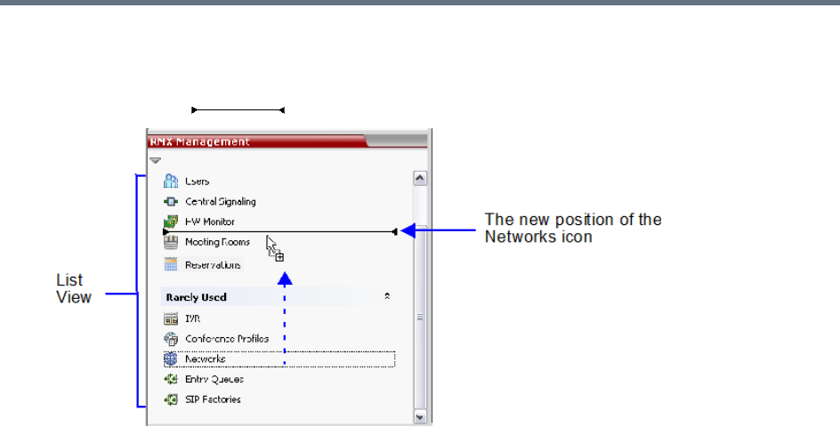
Use the RMX Web Client
Polycom®, Inc. 690
To move items within and between the Frequently Used and Rarely Used sections:
1In the RMX Management pane, drag the icon of the item you wish to move to the desired position.
An indicator line ( ) appears indicating the new position of the icon.
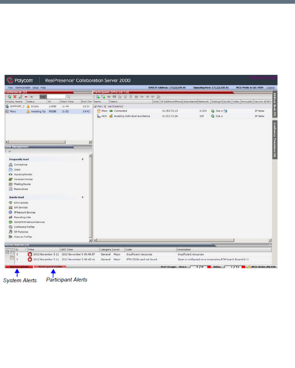
Polycom®, Inc. 691
Administration and Utilities
System and Participant Alerts
The MCU alerts users to any faults or errors the MCU encountered during operation. Two indication bars
labeled System Alerts and Participant Alerts signal users of system errors by blinking red in the event of an
alert.
Collaboration Server 1500/1800/2000/4000 Status Bar
The System Alerts indication bar blinks red prompting the user to view the active alarms. Once viewed, the
System Alerts indication bar becomes statically red until the errors have been resolved in the MCU.
The Participants Alerts indication bar blinks red indicating participant connection difficulties in
conferences. Once viewed, the Participant Alerts indication bar becomes statically red until the errors have
been resolved in the MCU.
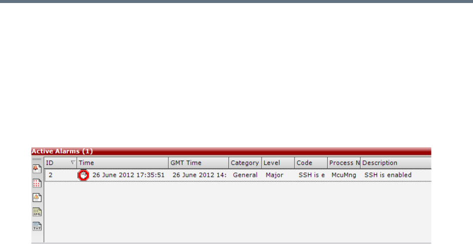
Administration and Utilities
Polycom®, Inc. 692
System Alerts
System Alerts are activated when the system encounters errors such as a general or card error. The system
errors are recorded by the Collaboration Server and can be generated into a report that can be saved in *.txt
format.
To view the System Alerts list:
1Click the red blinking System Alerts indication bar.
The Active Alarms pane opens. This screen indicates what events have not been resolved.
The following columns appear in the Active Alarms pane:
Administration and Utilities
Polycom®, Inc. 693
For more information about the Active Alarms, see Appendix B - Active Alarms.
2Click one of the following buttons to view its report in the System Alerts pane:
Active Alarms Pane Columns
Field Description
ID An identifying number assigned to the system alert.
Time Lists the local date and time that the error occurred. This column also
includes the icon indicating the error level (as listed in the level column).
GMT Time Lists the date and time according to Greenwich Mean Time (GMT) that
the error occurred.
Category Lists the type of error. The following categories may be listed:
• File indicates a problem in one of the files stored on the MCU’s hard disk.
•Card indicates problems with a card.
• Exception indicates software errors.
• General indicates a general error.
• Assert indicates internal software errors that are reported by the software
program.
•Startup indicates errors that occurred during system startup.
•Unit indicates problems with a unit.
•MPL indicates an error related to a Shelf Management component (MPL
component) other than an MPM, RTM or switch board (Collaboration Server
1500/2000/4000 only).
Level Indicates the severity of the problem, or the type of event. There are three fault
level indicators:
- Major Error
- System Message
- Startup Event
Code Indicates the problem, as indicated by the error category.
Process Name Lists the type of functional process involved.
Description When applicable, displays a more detailed explanation of the cause of the
problem.
System Alerts Buttons
Active Alarms (default) – this is the default reports list that is displayed when clicking the
System Alerts indication bar. It displays the current system errors and is a quick indicator of
the MCU status.
Faults Full List - A list of all system faults.
Note: Viewed when logged in as a special support user.
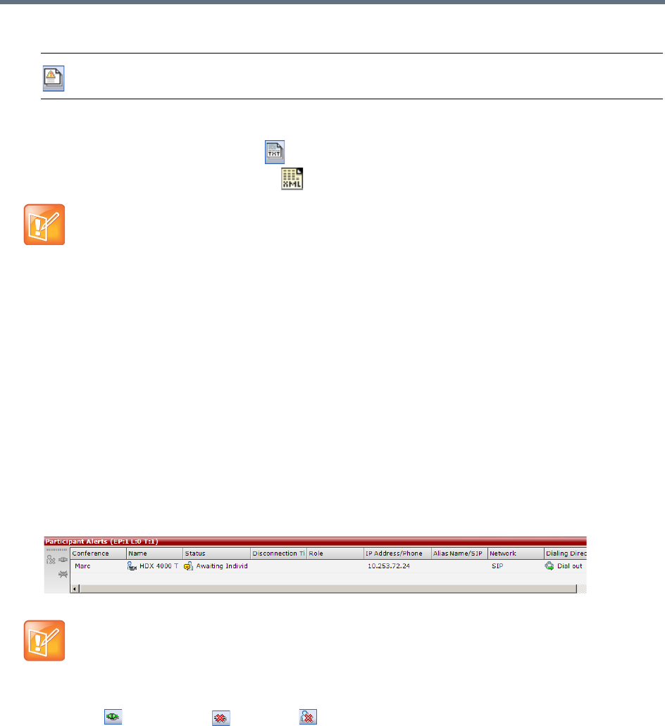
Administration and Utilities
Polycom®, Inc. 694
3To save the Active Alarms, Faults Full List or Faults report:
To a text file, click Save to Text .
To an XML file, click Save to XML .
The Save dialog window opens.
4Select a destination folder, and enter the file name.
5Click Save.
Participant Alerts
Participant Alerts enables users, participants and conferences to be prompted and currently connected.
This includes all participants that are disconnected, idle, on standby or waiting for dial-in. Alerts are intended
for users or administrators to quickly see all participants that need their attention.
To view the Participants Alerts list:
1Click the red blinking Participants Alerts indication bar.
The Participant Alerts pane opens.
2To resolve participant issues that created the Participant Alerts, the administrator can either
Connect , Disconnect or Delete a participant.
Faults List – a list of faults that occurred previously (whether they were solved or not) for
support or debugging purposes.
The Save to XML button is only available when logged in as a special support user.
The Participant Alerts pane displays similar properties to that of the Participant List pane. For
more information, see Participant Level Monitoring.
System Alerts Buttons
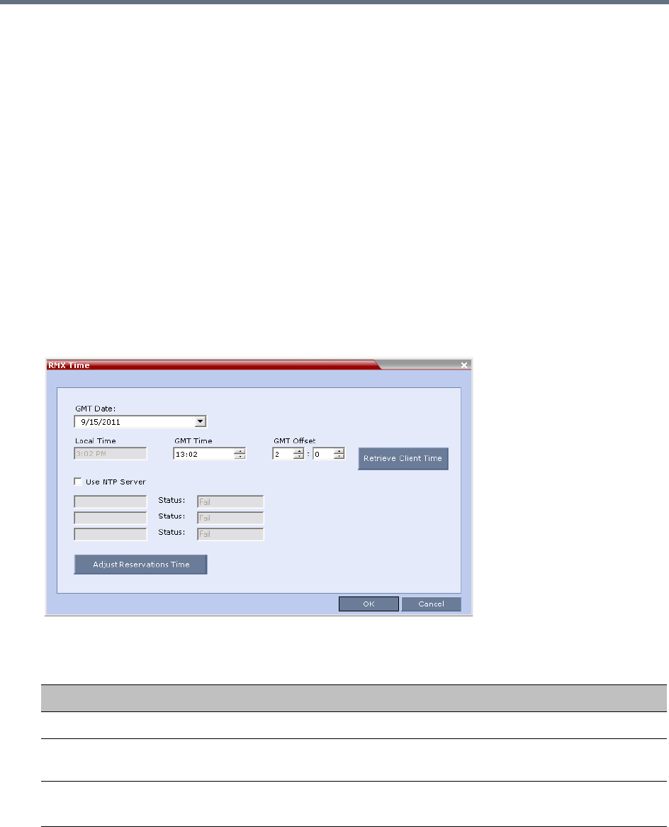
Administration and Utilities
Polycom®, Inc. 695
RMX Time
To ensure accurate conference scheduling, the MCU has an internal clock that can function in standalone
mode, or in synchronization with up to three Network Time Protocol (NTP) servers.
NTP Servers can be used if:
●NTP servers use Version 4 as it is the only supported protocol.
●If applicable, daylight saving adjustments must be implemented by the administrator whether the
MCU is in standalone mode or synchronized with NTP Servers.
Altering the clock
The MCU’s date and time can be set manually or enabled to synchronize with external NTP servers.
To Alter the MCU Time:
1On the Collaboration Server menu, select Setup > RMX Time.
The RMX Time dialog box opens.
2View or modify the following fields:
RMX Time – Fields Properties
Field Description
GMT Date The date at Greenwich, UK.
Local Time The MCU’s local time settings, are calculated from the GMT Time and the GMT
Offset.
GMT Time The MCU’s current GMT Time settings.
Select the Up or Down arrows to alter the GMT Time on the MCU.
Administration and Utilities
Polycom®, Inc. 696
GMT Offset The time zone difference between Greenwich and the MCU’s physical location
in hours and minutes.
Select the Up or Down arrows to alter the GMT Offset time on the MCU. To
enter a negative offset either type a minus in the hour box or use the down
arrow and decrease the offset below zero.
Retrieve Client Time Click this button to automatically update the MCU’s GMT Date, Time and Offset
to match that of the workstation.
Use NTP Server Select this check box to synchronize the time with up to three NTP servers.
When selected, the manual GMT Date and GMT Time setting options are
disabled. The GMT Offset fields are still active.
To implement this mode an external connection to an NTP server must be
enabled.
Enter the IP addresses of the required NTP servers in order of precedence.
The Status field indicates whether registration with the NTP Server failed or
succeeded.
Note: TheCollaboration Server will not use a time source such as a
Windows-based, W32Time service (SNTP) time service. Only full-featured
(below Stratum 16) NTP Servers are considered sufficiently reliable for
high-accuracy timing environments.
Adjust Reservations
Time
Use this button to adjust the start time of all the reservations in one operation.
For more information see Adjusting the Start Times of all Reservations.
Not supported in the RealPresence Collaboration Server.
After resetting the MCU a delay may occur when synchronizing with the external NTP server.
RMX Time – Fields Properties
Field Description

Administration and Utilities
Polycom®, Inc. 697
Resource Management
This section describes how the MCU resources are managed by the MCU and how they are used by the
MCU to connect participant to conferences.
This section describes:
●Resource Capacity
●AVC Conferencing - Voice
●Video/Voice Port Configuration - MPMx
●Displaying the Resource Report
●MCU Resource Management by RealPresence Resource Manager, Polycom CMA and Polycom
RealPresence DMA System
Resource Capacity
The MCU resources are determined by the MCU type, Card Configuration Mode and the system license you
have purchased. The total number of licensed resources is shown in the System Information.
Collaboration Server (RMX) 1500 supports one Card Configuration Mode: MPMx, and contains a single
card. It supports up to 4 ISDN/PSTN E1/T1 connections.
Collaboration Server (RMX) 2000/4000 support two Card Configuration Modes: MPMx or MPMRx.
Collaboration Server (RMX) 2000 can include up to two media cards and Collaboration Server (RMX) 4000
can include up to four media cards. Both include one RTM-ISDN card with up to 7 E1 or 9 T1 connections.
Collaboration Server (RMX) 1800 does not contain any MPM media cards, yet it supports one media card
type similar to the MPMRx card, and therefore has similar capabilities (in terms of the media card).
Collaboration Servers 1800 containing 3 DSP cards and built in ISDN also support up to 4 ISDN/PSTN
E1/T1 connections.
Collaboration Server (RMX) 1800-0 does not contain any DSP cards.
MCU Capacities in CP Only Conferencing and SVC Only Conferencing
The following table summarizes the resource capacities of fully configured (with all media cards at their full
capacity) and fully licenced Collaboration Servers with the various card types per resolution in AVC CP only
Conferencing mode or in SVC only conferences (and not in mixed CP and SVC conferences).
Three assembly variations, MPMx-S, MPMx-D and MPMx-Q, differing in resource capacity, are
available in RealPresence Collaboration Server (RMX) 1500. For capacity details, see
Administration and Utilities
Polycom®, Inc. 698
Resource Usage in AVC CP Conferencing
Video resources usage varies according to the video resolution used by the endpoints. The higher the video
resolution (quality), the greater the amount of video resources consumed by the MCU. The following table
shows the number of video resources used for each resolution.
The port consumption ratios of different calls against that of a HD720p30 call are as shown in this table.
Resource Capacities for Full Capacity Collaboration Server per Resolution in AVC CP Only or SVC Only
Resource Type
Maximum Possible Resources per Collaboration Server Model
1500 1800* 2000** 4000**
MPMx 1 card 3 cards MPMx MPMRx-D MPMx MPMRx-D
Voice (IP) 360 300 300 720 260 1440 520
Voice (PSTN) 120 N/A 120 400 260 400 400
CIF H.263 60 25 75 120 130 240 260
CIF H.264 90 50 150 180 260 360 520
CIF 60 H.264 60 12 37 120 65 240 130
SD30 H.264 60 50 150 120 260 240 520
4CIF H.263 30 25 75 60 130 120 260
4CIF 60 / SD 60 30 12 37 60 65 120 130
HD720p30 30 25 75 60 130 120 260
HD1080p30 / HD720p60
Symmetric 15 12 37 30 65 60 130
HD1080p60 Asymmetric 7 N/A N/A 30 NA 60 NA
HD1080p60 Symmetric N/A 6 18 N/A 32 N/A 65
SVC 90 75 225 180 390 360 780
SVC 1080p ports N/A 150 150 N/A 50 N/A 50
* Collaboration Server 1800: For a maximum license of 75 ports.
** Collaboration Server 2000/4000: For a maximum license of 65 ports.
Administration and Utilities
Polycom®, Inc. 699
Resource Usage in SVC Conferencing
During a SVC conference, each SVC-endpoint uses a video port that is equivalent to a third of HD720p30
port. When sharing content an additional video resource is used.
MCU Capacities in Mixed CP and SVC Conferencing
In a mixed CP and SVC conference, video resources are used according to the amount of both AVC and
SVC participants in the conference.
Port Consumption Ratios of Different Calls
Card Type/
Conferencing
Mode HD1080p60 HD1080p30 HD720p30 AVC SD AVC CIF Audio SVC
MPMRx
CP only or
SVC only
4 2 1 0.5 0.5 0.5 0.3333
MPMx
CP only or
SVC only
N/A 2 1 0.5 0.3333 0.0833 0.3333
Resource Capacities for Full Capacity Collaboration Server per Resolution in Mixed CP and SVC Conferencing
Resource Type
Maximum Possible Resources per Collaboration Server Model
1500 1800* 2000** 4000**
MPMx 1 card 3 cards MPMx MPMRx-D MPMx MPMRx-D
Voice (IP) 360 26 75 720 150 1440 300
Voice (PSTN) 120 120 120 400 150 300 300
CIF H.264 26 75 150 300
SD30 H.264/4CIF 30 26 75 60 150 120 300
HD720p30 20 14 42 40 84 80 168
HD1080p30 10 8 25 20 42 40 84
HD1080p60 5 N/A N/A 10 N/A 20 N/A
SVC 90 52 150 180 300 360 600
SVC 1080p ports N/A 120 120 N/A 50 N/A 50
* Collaboration Server 1800: For a maximum license of 75 ports for 3 cards and 25 ports for 1 card
configurations.
** Collaboration Server 2000/4000: For a maximum license of 65 ports.
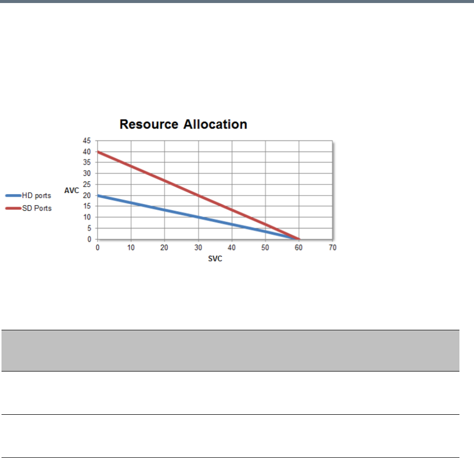
Administration and Utilities
Polycom®, Inc. 700
The ratio of resources in a mixed conference is one AVC HD (720p30) video resource to three SVC video
resources, meaning for each AVC HD video resource, three SVC video resources can be allocated.
For example, in a mixed AVC/SVC conference, 10 HD AVC ports and 30 SVC ports can be used,
maintaining ratio of one HD port to three SVC ports.
The following diagram illustrates the amount of AVC to SVC port resources that are used in a mixed
AVC/SVC conference:
Resource Usage in Mixed CP and SVC Conferencing
AVC Conferencing - Video Switching Resource Capacity
During a Video Switching conference, each endpoint uses one video (CIF) port.
The following table summarizes the resource capacities of fully configured MCUs with the various card types
per line rate in VSW Conferencing mode.
Port Consumption Ratios of Different Calls
Card Type/
Conferencing
Mode HD1080p60 HD1080p30 HD720p30 AVC SD AVC CIF Audio SVC
MPMRx
mixed CP and
SVC
N/A 3 1.5 0.75 0.75 0.75 0.3333
MPMx
mixed CP and
SVC
N/A 3 1.5 0.75 0.75
Administration and Utilities
Polycom®, Inc. 701
Resource Usage in AVC CP Conferencing
Video resources usage varies according to the video resolution used by the endpoints. The higher the video
resolution (quality), the greater the amount of video resources consumed by the MCU.
For information on resource usage vs. resolution, see Polycom RealPresence Collaboration Server
1500/1800/2000/4000 (depending on the machine) Hardware Guide.
AVC Conferencing - Voice
In Collaboration Server 1500/2000/4000 in MPMx Card Configuration Mode, one Audio Only resource is
used to connect a single voice participant when CIF resources have been converted to Audio Only.
However, if no CIF resources were converted, Audio Only endpoints use one CIF video resource per
connection.
When video ports are fully used, the system cannot use free audio ports for video. When audio port
resources are fully used, video ports can be used, using one video port to connect one voice participant.
In Collaboration Server 1500/1800/2000/4000 in MPMRx Card Configuration Mode, a voice port equals a
CIF video port and there is no differentiation between voice and video ports.
Resource Capacity Modes
The installed media card type (MPMx or MPMRx) determines the Card Configuration Mode, which in turn
determines the resource allocation method that can be selected for the MCU. The resource allocation
method determines how the system resources are allocated to the connecting endpoints and it is defined in
the Video/Voice Port Configuration.
Resource Capacity Allocation per Line Rate in VSW Conferencing Mode
Resource Type
Maximum Possible Resources (CIF Video Resources)
RMX 1500 RMX 1800-3 RMX 2000 RMX 4000
MPMx MPMx MPMRx MPMx MPMRx
Voice (IP) 360 360 720 260 1440 520
Voice (PSTN) 120 120 400 260 400 400
VSW 2Mb 80 200 160 130 320 260
VSW 4Mb 40 150 80 130 160 260
VSW 6Mb 20 100 40 100 80 200
ISDN 4 E1 or 9 T1
(per RTM ISDN card) 7 E1 or 9 T1 (per RTM ISDN card)
MCUs with 500MB of memory can support a maximum of 400 simultaneous participant calls,
regardless of how system resources are allocated.
MCUs with 1000MB of memory are not subject to this limitation.
MCU memory size is listed in the Administration > System Information properties box. For more
information see System Information.

Administration and Utilities
Polycom®, Inc. 702
Flexible Resource Capacity™ is the allocation mode that is used in all versions and can be used in all Card
Configuration Modes and applies to all Conferencing Modes (SVC and AVC conferencing). The resources
are only set to audio and video as a pool and the system allocates the resources according to the connecting
endpoints. This mode offers flexibility in resource allocation and is available in MPMx and MPMRx Card
Configuration Modes.
In Flexible Resource Capacity mode, in MPMx and MPMRx Card Configuration Modes, the maximum
number of resources is based on the system license, regardless of the hardware configuration of the MCU.
These resources are allocated as CIF resources by default.
Example: If the MCU is licensed for 80 video resources, but only one Media card is currently installed in the
MCU, the system lets you allocate 80 ports although only 40 video resources are available for participant
connection. (However, an active alarm will be added to the Active Alarms list indicating a resource
deficiency).
Video/Voice Port Configuration - MPMRx
Although the Video/Voice Configuration dialog box is displayed for Collaboration Servers 2000/4000 with
MPMRx media cards installed, Video/Voice Configuration is not supported.
These MCUs and the Collaboration Server 1800 will allocate the same amount of system resources to voice
(audio) participants, as those allocated to CIF video participants. For more information see Resource
Reports.
Video/Voice Port Configuration - MPMx
The Video/Voice Port Configuration dialog box enables you to configure the resources per resource type
using Flexible Resource Capacity Mode if the MCU has MPMx media cards installed.
Flexible Resource Capacity Mode
Flexible Resource Capacity is the default mode for MPMx media cards.
All resources are initially allocated as HD720p30 video ports. The administrator can allocate some or all of
these resources as Voice resources and let the system allocate the remaining Video resources
automatically as participants connect to conferences. The number of resources automatically allocated by
the system resources per endpoint is according to the participant’s endpoint type, capabilities and line rate.
Fixed Resource Capacity mode is disabled and cannot be selected in the Video/Voice Port
Configuration.
If Fixed Resource Capacity mode was active at the time of an upgrade, Flexible Resource Capacity
mode will automatically be enabled, the settings from the last time Flexible Resource Capacity mode
active on the Collaboration Server are implemented when the upgrade is complete.
If the system runs out of voice ports, voice endpoints cannot connect to available video ports.
Conversely, video endpoints cannot connect to available voice ports.
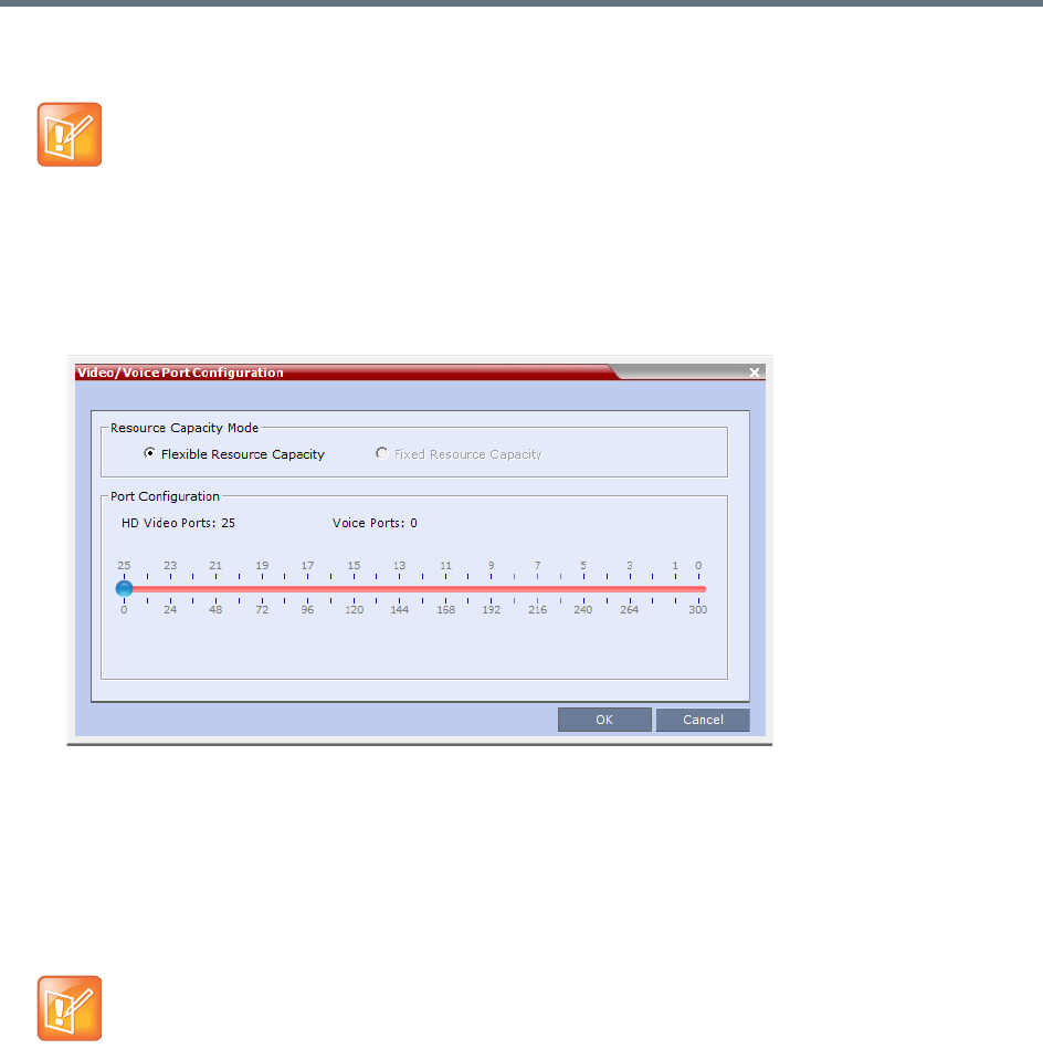
Administration and Utilities
Polycom®, Inc. 703
Configuring the Video/Voice Resources
To allocate Voice resources:
1In the RMX menu, select Setup > Video/Voice Port Configuration.
The Video/Voice Port Configuration dialog box is displayed.
A slider is displayed, calibrated according to the number of HD720p30 video licenses purchased for
the MCU.
2Move the slider (to the right) to increase the number of Voice ports allocated.
As the slider moves, HD720p30 video ports are converted to voice ports, with each HD720p30 video
port converting to 12 voice ports.
3Click OK.
Forcing Video Resource Allocation to CIF Resolution
You can set the MCU to allocate one CIF video resource to an endpoint, regardless of the resolution
determined by the Conference Profile parameters. This forcing saves resources and enables more
endpoints to connect to conferences.
The forcing is done by modifying the system configuration and it applies to all conferences running on the
MCU.
You can specify the endpoint types for which resource allocation can be forced to CIF resource, enabling
other types of endpoints to use higher resolutions in the same conference. For example, you can force the
•Resource re-configuration should only be performed when no conferences are running on the
MCU.
•Updating the configuration sequentially requires a 10 seconds wait between updates, to let the
system complete the update process.
On the RMX1500 MPMx-Q assembly, the use of HD with Continuous Presence requires an
additional license. In the Resource Report and Resolution Configuration panes, HD settings are
displayed but are not enabled and if HD is selected the system will enable SD by default.

Administration and Utilities
Polycom®, Inc. 704
system to allocate one CIF video resource to CMAD and VSX endpoints while HDX endpoints can connect
using SD or HD video resources.
Once the endpoint connects to the conference, its type is identified by the Collaboration Server and, if
applicable, the Collaboration Server will connect it using one CIF resource, even if a higher resolution can
be used.
To force CIF resource:
1On the Collaboration Server menu, select Setup > System Configuration.
The System Flags dialog box opens.
2In the MCMS_PARAMETERS tab, click New Flag.
The New Flag dialog box is displayed.
3In the New Flag field enter the flag name: FORCE_CIF_PORT_ALLOCATION
4In the Value field enter the product type to which the CIF resource should be allocated. Possible
values are VSX nnnn where nnnn represents the model number for example, VSX 8000.
5Click OK.
The new flag is added to the flags list.
Reset the MCU for changes to take effect. For more details, see the Resetting the Collaboration Server.
To cancel the forcing of CIF resource:
1On the Collaboration Server menu, select Setup > System Configuration.
The System Flags dialog box opens.
2In the MCMS_PARAMETERS tab, select the flag FORCE_CIF_PORT_ALLOCATION and click Edit
Flag or double-click it.
3In the New Value field, clear the value entries.
4Click OK.
Reset the MCU for changes to take effect. For more details, see the Resetting the Collaboration Server.
Resource Reports
When viewing the Collaboration Server resource report, the resource allocations are described in AVC
HD720p30 units.
The Resource Report also includes a graphic representation of the resource usage. One resource report is
available for all resource usage including SVC-based endpoints.

Administration and Utilities
Polycom®, Inc. 705
Displaying the Resource Report
1In the main toolbar, select Administration > Resource Report.
For each resource type, the Resource Report includes the following columns:
Resource Report for Collaboration Servers 1500 and 2000/4000 with MPMx
The Resource Report details the current availability and usage of the system resources for both AVC and
SVC-based endpoint, displaying the number of free and occupied audio and video resources. A Resources
Graph is displayed in addition to the Resources table.
Example: A Collaboration Server with MPMx media cards installed has:
●30 licensed HD720p30 resources.
●6 of its 30 HD720p30 resources allocated as Audio = 72 Audio resources (6x12).
●All 72 Audio resources free (green).
●The remaining 24 HD720p30 resources allocated as Video resources.
●3 of the 24 HD720p30 resources are occupied (red) while the remaining 21 are free.
Resource Report Fields Parameters
Column Description
Type The type of audio/video resources available - both AVC and SVC-based
endpoints (and resources).
Occupied The number of MCU resources that are used by connected AVC and
SVC-based participants or reserved for defined participants.
Free The number of MCU resources available for connecting AVC and SVC-based
endpoints.
Total The Total column displays the total number of resources of that type as
configured in the system (Occupied and Free). This number reflects the
current audio/video port configuration (for AVC and SVC-based conferencing).
Any changes to the resource allocation will affect the resource usage displayed
in the Resource Report.
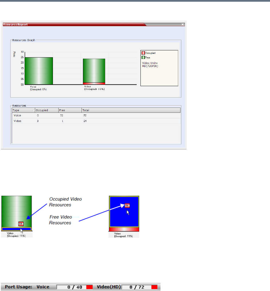
Administration and Utilities
Polycom®, Inc. 706
The Resource Report is displayed as follows:
Resource usage is displayed for Voice and Video resources, where the number of video resources is
represented in the equivalent of HD720p30 resources. The number represents a pool of both AVC and SVC
resources. They are displayed as percentages of the total resource type.
The actual number of occupied or free resources can also be displayed by moving the cursor over the
columns of the bar graph. Moving the cursor over the Video bar displays the following:
Port Gauges
The Port Gauges in the Status Bar show the numbers as they appear in the resource report. In the following
example, 0 of the 40 Audio (Voice) resources are shown as occupied and 8 of the 72 Video resources are
shown as occupied.
Resource Reports for Collaboration Server 1800 and 2000/4000 with MPMRx
Collaboration Servers with MPMRx media cards installed do not differentiate between Video and Voice
(Audio) resources. These MCUs allocate the same amount of system resources to Voice (Audio)
participants, as those allocated to CIF Video participants.
Example: A Collaboration Server with MPMRx media cards installed has 200 licensed HD720p30
resources, all of which are free.
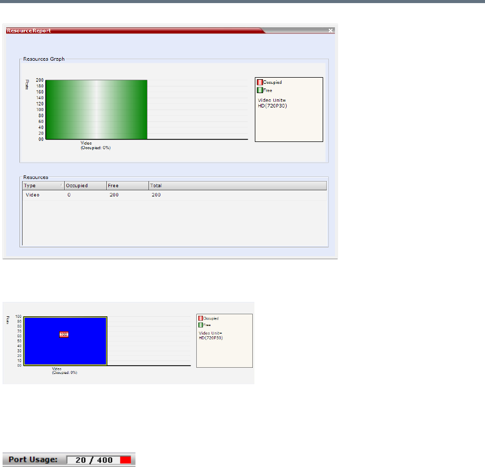
Administration and Utilities
Polycom®, Inc. 707
The actual number of occupied or free resources can also be displayed by moving the cursor over the
columns of the bar graph. Moving the cursor over the Video bar displays the following view:
Port Gauge
The Port Gauge in the Status Bar show the numbers as they appear in the resource report. In the following
example, 20 of the 400 system resources are shown as occupied.

Administration and Utilities
Polycom®, Inc. 708
Resource Capacities in AVC CP, SVC and Mixed Mode Conferences in
MPMx Card Configuration Mode
When viewing the Collaboration Server resource report for mixed CP and SVC conferences, the resource
allocations are described in AVC HD720p30 units. A port ratio of 1 AVC HD port will equal 2 AVC SD ports,
which equals 3 SVC ports (in a non-mixed conference). When the Collaboration Server is reporting the
available capacity, it will appropriately round up the remaining capacity to the nearest whole value of
available ports. For example, one SVC endpoint in a conference is equal to 1/3 of the resource value. The
resource report displays this as one full resource used. Two SVC endpoints is equal to 2/3 of the resource
value. Therefore, the resource report displays this as one full resource used, and so forth. The following
tables show the actual resource capacity utilization for both CP only and mixed CP and SVC conferences
in AVC HD720p30 units for each port type for a single MPMx media board at full capacity
Resource Capacities in AVC CP, SVC and Mixed Mode Conferences in
MPMRx Card Configuration Mode
Collaboration Server 1800/2000/4000 Resource Capacities are set out below.
Collaboration Server 1800 Resource Capacity
The RMX 1800 system allocates port resources in AVC HD 720 p30 units. The number of unit ports each
types of calls requires differs for AVC-SVC mixed conferences and non-mixed conferences.
Resource Capacity Allocation Per Port Type
Port Type Non-Mixed Conferences Mixed CP and SVC Conferences
AVC HD 1 1.5 *
AVC SD 0.5 0.75 *
AVC CIF 0.333 0.75 *
SVC 0.333 0.333
* Resources are consumed at this rate only after the conference contains a mix of endpoints.
Resource Capacity Utilization Per Port Type per MPMx Card
Port Type
Maximum Ports in Non-mixed
Conferences
Maximum Ports in Mixed CP and SVC
Conferences
Maximum number of
licences
30
AVC HD 30 20
AVC SD 60 40
AVC CIF 90 40
SVC 90 90
Administration and Utilities
Polycom®, Inc. 709
Listed are the resource capacities for different system configurations, licenses, and conferencing modes.
Resource Capacity in Non-Mixed Conferences
The port consumption ratios of different calls against that of a HD 720 p30 call are as shown in this table.
In other words, to make a1080p60 call, you need four 720p 30 ports; to make a 1080p 30 call, two 720p 30
ports; and so forth.
When the required resource is not a whole number, it’s rounded up to the nearest whole number. For
example, to make an SVC call requiring1/3 of an HD 720 p30 port. In fact, one port will be allocated.
Resource Capacity in Mixed Conferences
The the port consumption of different calls in mixed conferences are shown in the following table.
In other words, to make one 720 p30 call in a mixed conference, you need two license ports; to make one
1080 p30 call, three license ports; and so forth.
When the required resource is not a whole number, it’s rounded up to the nearest whole number. For
example, to make an SVC call requiring1/3 of a license port. In fact, one port will be allocated.
For more information about resources licenses and capacities for the various Collaboration Server 1800
media card configurations, see the Realpresence Collaboration Server (RMX) 1800 Hardware Guide.
Port consumption ratios of different calls
HD720p 30 HD1080p 60 HD1080p 30 SD CIF Audio SVC
1 4 2 1/21/21/31/3
Port Consumption Ratios, in Mixed Conferences
HD720p30 HD1080p60 HD1080p30 AVC SD AVC CIF Audio SVC
1.5 NA 3 3/4 3/4 3/4 1/3
Administration and Utilities
Polycom®, Inc. 710
Collaboration Server 2000/4000 Resource Capacity
The Collaboration Server Models 2000/4000 Resource Capacities are set out below.
Resource Capacity in Non-Mixed Conferences
The port consumption ratios of different calls against that of a HD720p30 call are as shown in this table.
In other words, to make one1080p60 call, you need 4x 720p 30 ports; to make one 1080p 30 call, 2x 720p
30 ports; and so forth.
When the required resource is not a whole number, it’s rounded up to the nearest whole number. For
example, to make an SVC call requiring1/3 of an HD720p30 port. However in the Port Gauge, one port
appears allocated.
Resource Capacity in Mixed Conferences
The following table shows the port consumption ratios of different calls against that of an HD720p30 call.
In other words, to make one 1080p30 call, you need 3x 720p30 ports; to make one 720p30 call, 1.5x 720p30
ports; and so forth.
When the required resource is not a whole number, it’s rounded up to the nearest whole number. For
example, to make an SVC call requiring1/3 of an HD720p30 port. However in the Port Gauge, one port
appears allocated.
For more information about resources licenses and capacities for the various Collaboration Server
2000/4000 media card configurations, see the RealPresence Collaboration Server (RMX) 2000 Hardware
Guide and RealPresence Collaboration Server (RMX) 4000 Hardware Guide.
ISDN/PSTN
RMX 1500 supports one ISDN card with 4 E1/T1 PRI lines.
RMX 1800-3 with built-in ISDN supports 4 E1/T1 PRI lines.
On the RMX 2000/4000 a maximum of two RTM ISDN cards are supported, each providing connection for
up to either 7 E1 or 9 T1 PRI lines.
E1 and T1 connections cannot be used simultaneously.
The following table lists the ISDN supported bit rates and their respective participant connection capacities
per RTM ISDN card:
Port Consumption Ratios of Different Calls
HD720p30 HD1080p60 HD1080p30 AVC SD AVC CIF Audio SVC
1 4 2 1/2 1/2 1/2 1/3
Port Consumption Ratios, in Mixed Conferences
HD720p30 HD1080p60 HD1080p30 AVC SD AVC CIF Audio SVC
1.5 NA 3 3/4 3/4 3/4 1/3
Administration and Utilities
Polycom®, Inc. 711
If the conference bit rate is above 128Kbps but does not match any of the bonded bit rates, participants are
connected at the highest bonded bit rate that is less than the conference bit rate. For example: If the
conference bit rate is 1024Kbps, the participant is connected at 768Kbps
MCU Resource Management by RealPresence Resource Manager, and
Polycom RealPresence DMA System
When the RealPresence Resource Manager, and Polycom RealPresence DMA system are part of the
solution, following a request by the RealPresence Resource Manager and Polycom RealPresence DMA
system, the MCU will send updates on resource usage to the DMA, which updates its own resource usage
for the MCU. This provides better management of the Collaboration Server resources by the RealPresence
Resource Manager, and Polycom RealPresence DMA system.
Guidelines
●Resource usage updates from RMX to the DMA are supported only for Collaboration Servers with
MPMx card(s).
●Following requests sent by the RealPresence DMA system, the Collaboration Server will send the
number of occupied resources for a conference or total for the MCU.In Flexible Resource Capacity
Mode, the DMA receive information about how many Video (CIF) and Audio resources are occupied
per conference or MCU according the request type sent by the DMA.
●Occupied resources are resources that are connected to ongoing conferences. Disconnected
endpoints in an ongoing conference are not counted as occupied resources.
RMX 1500/2000/4000 ISDN – E1/T1 Connection Capacity vs. Bit rate
Bit Rates
(Kbps)
(Bonded)
Number of Participants per RTM ISDN Card
E1 T1 Type
64 120 92 Voice / PSTN
128 40 40
Video
192 40 40
256 40 40
320 40 40
384 34 34
512 25 25
768 17 17
1152 11 11
1472 9 9
1536 8 8
1920 7 6
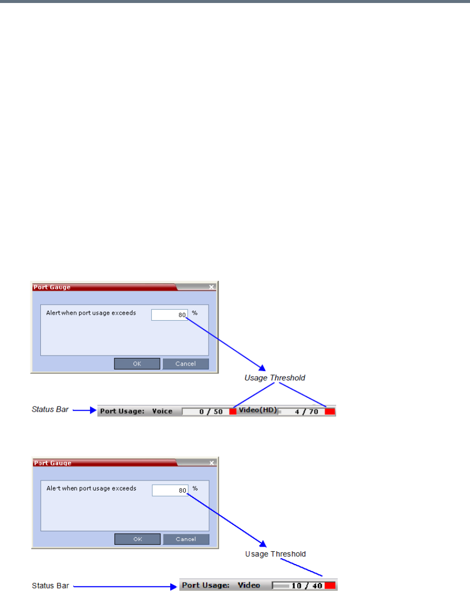
Administration and Utilities
Polycom®, Inc. 712
●An ongoing conference that does not include participants and the Send Content to Legacy
Endpoints option is disabled does not occupy resources. If the Send Content to Legacy Endpoints
option is enabled, the conference occupies one SD resource.
Port Usage Threshold
The Collaboration Server can be set to alert the administrator to potential port capacity shortages. A
capacity usage threshold can be set as a percentage of the total number of licensed ports in the system.
When the threshold is exceeded, a System Alert is generated.
The default port capacity usage threshold is 80%.
The administrator can monitor the MCU’s port capacity usage via the Port Gauge in the Status Bar of the
Collaboration Server Web Client.
Setting the Port Usage Threshold
To Set the Port Usage Threshold:
1In the Setup menu, click Port Gauge to open the Port Gauge dialog box.
Port Gauge Threshold Setting - RealPresence Collaboration Server (RMX) 1500/2000/4000 with MPMx
Port Gauge Threshold Setting - RealPresence Collaboration Server 1800 or 2000/4000 with MPMRx
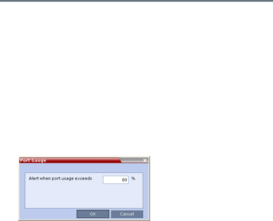
Administration and Utilities
Polycom®, Inc. 713
2Enter the value for the percentage capacity usage threshold.
The value is applied to the Audio and video resources according to the Video/Voice Port
Configuration.
The high Port Usage threshold represents a percentage of the total number of video or voice ports
available. It is set to indicate when resource usage is approaching its maximum, resulting in no free
resources to run additional conferences. When port usage reaches or exceeds the threshold, the red
area of the gauge flashes. The default port usage threshold is 80%.
3Click OK.
SIP Dial-in Busy Notification
When the system flag SEND_SIP_BUSY_UPON_RESOURCE_THRESHOLD is set to YES (NO is the
default), it enables the MCU to send a busy notification to a SIP audio endpoint or a SIP device when dialing
in to the MCU whose audio resource usage exceeded the Port Usage threshold.
The Collaboration Server will send a SIP busy response to SIP audio endpoints when:
●The system flag SEND_SIP_BUSY_UPON_RESOURCE_THRESHOLD is set to YES (NO is the
default)
●The port usage threshold for Audio resources is exceeded. The threshold is defined in the Setup >
Port Gauge dialog box.
When the flag is set to YES, the system will allow SIP audio endpoints to connect to the MCU until the Port
Usage threshold is reached. Once this threshold is exceeded, the SIP audio endpoints will not be able to
connect, ensuring that the remaining system resources can be used by all other connections, including SIP
video, H.323 cascaded links, and ISDN video. When the call is rejected by the MCU because of lack of
resources, the appropriate indication will be sent by the MCU to the SIP audio endpoint.
For example, if the Port Gauge threshold is set to 80%, when 80% of the Audio resources are used, the
system will not allow additional SIP audio endpoints to connect and will send a busy notification to the
endpoint.
This does not affect the video resources usage.

Administration and Utilities
Polycom®, Inc. 714
Port Usage Gauges
The Port Usage Gauges are displayed in the Status Bar at the bottom of the RMX Web Client screen.
Port Usage Gauges
In the RealPresence Collaboration Server (RMX) 1500/2000/4000, the Port Usage gauges displays for the
selected MCU:
●The total number of Video or Voice ports in the system according to the Video/Voice Port
Configuration. The Audio gauge is displayed only if Audio ports were allocated by the administrator,
otherwise only the Video port gauge is displayed.
●The number of Video and Voice ports in use.
●The High Port Usage threshold.
In the RealPresence Collaboration Server 1800 and the RealPresence Collaboration Server (RMX)
2000/4000 with an MPMRx card, the Port Usage Gauge displays for the selected MCU:
●The total number of Video ports in the system.
●The number of Video ports in use.
●The High Port Usage threshold.
Port Gauges - RealPresence Collaboration Server (RMX) 1500/2000/4000 with MPMx
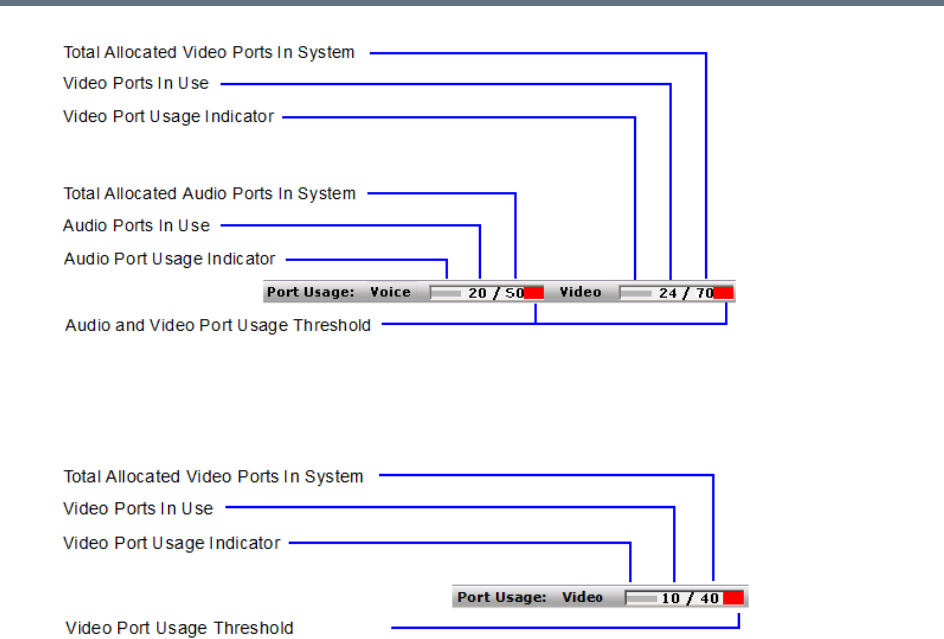
Administration and Utilities
Polycom®, Inc. 715
Port Gauges - RealPresence Collaboration Server 1800 and 2000/4000 with MPMRx
The basic unit used for reporting resource usage in the Port Gauges is HD720p30. Results are
rounded to the nearest integer.
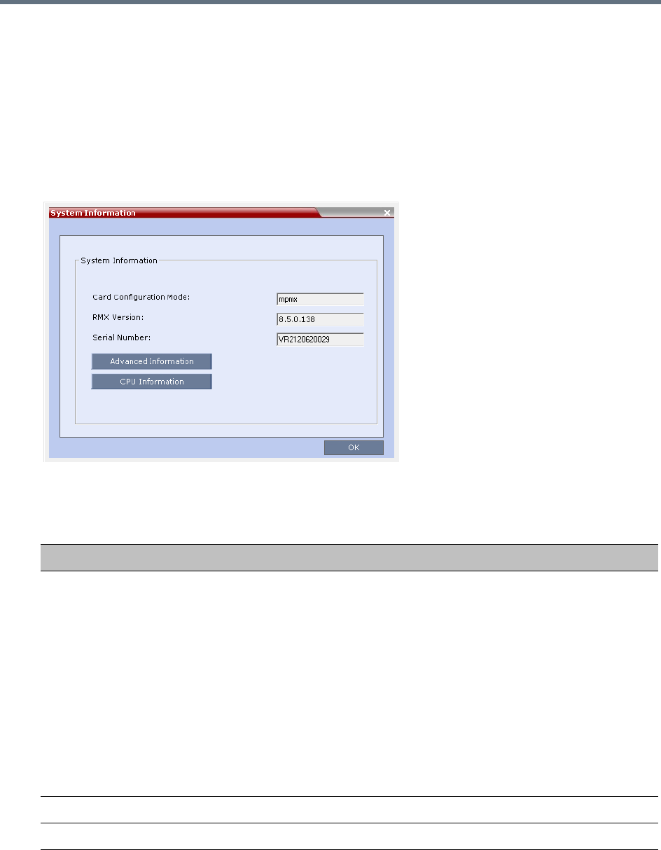
Administration and Utilities
Polycom®, Inc. 716
System Information
System Information includes License Information and general system information, such as system memory
size and Media Card Configuration Mode.
To view the System Information properties box:
»On the Collaboration Server menu, select Administration > System Information.
The System Information dialog box is displayed.
The following information is displayed:
System Information
Field Description
Card Configuration Mode
(N/A for Collaboration Server
1800)
Indicates the MCU configuration as derived from the installed media cards:
•MPMx: Only MPMx cards are supported. Any other media card in the
system is disabled.
•MPMRx: Only MPMRx cards are supported. Any other media card in the
system is disabled.
Notes:
•The RMX only switches between MPMx and MPMRx Card Configuration
Modes if MPMx or MPMRx cards are removed or swapped while it is
powered on. The Card Configuration Mode switch occurs during the next
restart.
•Installing or swapping MPMx or MPMRx cards while the system is off will
not cause a mode switch when the system is restarted; it will restart in the
Card Configuration Mode that was active previous to powering down.
RMX Version Displays the System Software Version of the MCU.
Serial Number Displays the Serial Number of the Collaboration Server unit.

Administration and Utilities
Polycom®, Inc. 717
SNMP (Simple Network Management Protocol)
SNMP enables managing and monitoring of the MCU status by external managing systems, such as HP
OpenView or through web applications.
The Collaboration Server’s implementation of SNMPv3 is FIPS 140 compliant.
MIBs (Management Information Base)
MIBs are a collection of definitions, which define the properties of the managed object within the device to
be managed. Every managed device keeps a database of values for each of the definitions written in the
MIB.
The SNMP systems poll the MCU according to the MIB definitions.
Traps
The MCU is able to send Traps to different managers. Traps are messages that are sent by the MCU to the
SNMP Manager when an event such as MCU Reset occurs.
Guidelines
●Version 1, Version 2 and Version 3 traps are supported.
●When SNMPv3 is selected only SNMPv3 Queries and Traps receive responses.
●A mixture of Version 1, Version 2 and Version 3 traps is not permitted.
●In Ultra Secure Mode:
Version 3 is the default for both SNMP Agent Version and SNMP Trap Version.
The default Authentication Protocol is SHA
The default Privacy Protocol is AES.
MIB Files
The H.341 standard defines the MIBs that H.320 and H.323 MCUs must comply with. In addition, other MIBs
should also be supported, such as MIB-II and the ENTITY MIB, which are common to all network entities.
The MIBs are contained in files in the SNMP MIBS sub-directory of the Collaboration Server root directory.
The files should be loaded to the SNMP external system and compiled within that application. Only then can
the SNMP external application perform the required monitoring tasks.
Private MIBs
●RMX-MIB (RMX-MIB.MIB)
Contains the statuses of the Collaboration Server: Startup, Normal and Major.
Contains all the Alarms of the Collaboration Server that are sent to the SNMP Manager.
The MULTI-MEDIA_MIB_TC must be compiled before compiling the other MIBs.

Administration and Utilities
Polycom®, Inc. 718
Support for MIB-II Sections
The following table details the MIB-II sections that are supported:
The Alarm-MIB
MIB used to send alarms. When a trap is sent, the Alarm-MIB is used to send it.
H.341-MIB (H.341 – H.323)
●Gives the address of the gatekeeper.
●Supports H.341-MIB of SNMP events of H.323.
Standard MIBs
This section describes the MIBs that are included with the Collaboration Server. These MIBs define the
various parameters that can be monitored, and their acceptable values.
Supported MIB-II Sections
Section Object Identifier
system mib-2 1
interfaces mib-2 2
ip mib-2 4
Standard MIBs
MIB Name Description
MULTI-MEDIA-MIB-TC
(MULTIMTC.MIB)
Defines a set of textual conventions used within the set of Multi Media MIB
modules.
H.320ENTITY-MIB
(H320-ENT.MIB)
This is a collection of common objects, which can be used in an H.320 terminal, an
H.320 MCU and an H.320/H.323 gateway. These objects are arranged in three
groups: Capability, Call Status, and H.221 Statistics.
H.320MCU-MIB
(H320-MCU.MIB)
Used to identify managed objects for an H.320 MCU. It consists of four groups:
System, Conference, Terminal, and Controls. The Conference group consists of the
active conferences. The Terminal group is used to describe terminals in active
MCU conferences. The Controls group enables remote management of the MCU.
H323MC-MIB
(H323-MC.MIB)
Used to identify objects defined for an H.323 Multipoint Controller. It consists of six
groups: System, Configuration, Conference, Statistics, Controls and Notifications.
The Conference group is used to identify the active conferences in the MCU. The
Notifications group allows an MCU, if enabled, to inform a remote management
client of its operational status.
Note: The Collaboration Server supports only one field in H.341-H323MC MIB. The
Collaboration Server reports the Gatekeeper address using H.341-H323MC MIB –
323McConfigGatekeeperAddress (0.0.8.341.1.1.4.2.1.1.4) in response to a query
from a manager.

Administration and Utilities
Polycom®, Inc. 719
Unified MIB
The Collaboration Server uses the Polycom Unified MIB, in addition to the RMX specific MIB. The Polycom
Unified MIB is an MIB that is used by many Polycom products. The following table describes the information
provided by the Collaboration Server in the Unified MIB.
MP-MIB (H323-MP.MIB) Used to identify objects defined for an H.323 Multipoint Processor, and consists of
two groups: Configuration and Conference. The Configuration group is used to
identify audio/video mix configuration counts. The Conference group describes the
audio and video multi-processing operation.
MIB-II/RFC1213-MIB
(RFC1213.MIB)
Holds basic network information and statistics about the following protocols: TCP,
UDP, IP, ICMP and SNMP. In addition, it holds a table of interfaces that the Agent
has. MIB-II also contains basic identification information for the system, such as,
Product Name, Description, Location and Contact Person.
ENTITY-MIB (ENTITY.MIB) Describes the unit physically: Number of slots, type of board in each slot, and
number of ports in each slot.
Unified MIB SNMP Fields
Name Type Description
Debug Boolean Indicates whether the unit is in a debugging state.
IncomingCallsReqrGK Boolean Indicates whether a gatekeeper is required to receive incoming
H.323 calls.
OutgoingCallsReqrGK Boolean Indicates whether a gatekeeper is required to make outgoing
H.323 calls.
HDBitrateThrshld Integer The minimum bit rate required by endpoints in order to connect
to an HD conference.
MaxCPRstln Integer Maximum resolution of a CP conference.
MaxCPRstlnCfg Integer Configured resolution for a CP conference.
EndpointDispayName String The name of the MCU that is displayed on the screen of
endpoints that are connecting to the conference.
PALNTSC NTSC / PAL /
AUTO
The video encoding of the RMX.
SeparateMgmtNet Boolean Indicates whether management network separation is enabled.
NumPorts Integer Total number of ports.
NumVideoPorts Integer Number of ports configured for video.
Standard MIBs
MIB Name Description

Administration and Utilities
Polycom®, Inc. 720
ServiceH323 Integer Indicates the status of H.323 capabilities:
1 - The service is enabled and operational.
2 - The service is enabled but is not operational.
3 - The service is disabled.
ServiceSIP Integer Indicates the status of SIP capabilities:
1 - The service is enabled and operational.
2 - The service is enabled but is not operational.
3 - The service is disabled.
ServiceISDN Integer Indicates the status of SIP capabilities:
1 - The service is enabled and operational.
2 - The service is enabled but is not operational.
3 - The service is disabled.
RsrcAllocMode Fixed/Flexible The resource allocation method which determines how the
system resources are allocated to the connecting endpoints.
McuSystemStatus Integer System State.
FanStatus Boolean Status of the hardware fan.
PowerSupplyStatus Boolean Status of the power supply.
IntegratedBoardsStatus Boolean Status of the integrated boards.
UltraSecureMode Boolean Indicates whether the RMX is operating in Ultra Secure Mode.
ChassisTemp Integer The temperature of the chasis.
NumPortsUsed Integer Number of ports currently in use.
NewCallsPerMinute Integer New calls in the last minute.
ScsfNewCallsPerMinute Integer Successful new calls in the last minute.
FldNewCallsPerMinute Integer Failed new calls in the last minute.
PctScsflNewCalls Integer Percentage of new calls in the last minute which were
successful.
CallsEndedScsflPerMin Integer Number of calls in the last minute which ended with a success
code.
CallsEndedFailedPerMin Integer Number of calls in the last minute which ended with a failure
code.
CallsEndedScsfl Integer Number of calls in the last minute which ended with a success
code.
CallsEndedFailed Integer Number of calls in the last minute which ended with a failure
code.
NumActvCnfrncs Integer Number of active conferences.
Unified MIB SNMP Fields
Name Type Description

Administration and Utilities
Polycom®, Inc. 721
Traps
Three types of traps are sent as follows:
●ColdStart trap. This is a standard trap which is sent when the MCU is reset.
An Example of a ColdStart Trap
●Authentication failure trap. This is a standard trap which is sent when an unauthorized community
tries to enter.
An Example of an Authentication Failure Trap
●Alarm Fault trap. The third trap type is a family of traps defined in the POLYCOM-RMX-MIB file,
these traps are associated with the Collaboration Server active alarm and clearance (proprietary
SNMP trap).
An Example of an Alarm Fault Trap
coldStart notification received from: 172.22.189.154 at 5/20/2007
7:03:12 PM
Time stamp: 0 days 00h:00m:00s.00th
Agent address: 172.22.189.154 Port: 32774 Transport: IP/UDP
Protocol: SNMPv2c Notification
Manager address: 172.22.172.34 Port: 162 Transport: IP/UDP
Community: public
Enterprise: enterprises.8072.3.2.10
Bindings (3)
authentication Failure notification received from: 172.22.189.154 at
5/20/2007 7:33:38 PM
Time stamp: 0 days 00h:30m:27s.64th
Agent address: 172.22.189.154 Port: 32777 Transport: IP/UDP
Protocol: SNMPv2c Notification
Manager address: 172.22.172.34 Port: 162 Transport: IP/UDP
Community: public
Enterprise: enterprises.8072.3.2.10
Bindings (3)

Administration and Utilities
Polycom®, Inc. 722
Each trap is sent with a time stamp, the agent address, and the manager address.
Status Trap
The MCU sends status traps for the status MAJOR - a trap is sent when the card/MCU status is MAJOR.
All traps are considered MAJOR.
RMX MIB entities that do not generate traps.
The following table lists the entities that appear in the RMX MIB of the SNMP that do not generate traps.
These traps will be displayed as Faults in the System Alerts pane (at the bottom of the RMX Web Client
screen.
SNMP MIB entities that do not generate traps
Key Description Comment
5002 Resource process did not receive the Meeting Room list during startup.
5004 Task terminated
5008 Low Processing Memory
5009 Low system Memory
5010 High system CPU usage
5014 High CPU utilization
5016 Process idle
5107 Failed to open Apache server configuration file
5108 Failed to save Apache server configuration file
rmxFailedConfigUserListInLinuxAlarmFault notification received
from: 172.22.189.154 at 5/20/2007 7:04:22 PM
Time stamp: 0 days 00h:01m:11s.71th
Agent address: 172.22.189.154 Port: 32777 Transport: IP/UDP
Protocol: SNMPv2c Notification
Manager address: 172.22.172.34 Port: 162 Transport: IP/UDP
Community: public
Bindings (6)
Binding #1: sysUpTime.0 *** (timeticks) 0 days 00h:01m:11s.71th
Binding #2: snmpTrapOID.0 *** (oid)
rmxFailedConfigUserListInLinuxAlarmFault
Binding #3: rmxAlarmDescription *** (octets) Insufficient resources
Binding #4: rmxActiveAlarmDateAndTime *** (octets)
2007-6-19,16:7:15.0,0:0

Administration and Utilities
Polycom®, Inc. 723
5110 A private version is loaded
5111 NTP synchronization failure
5112 Invalid date and time
5116 Incorrect Ethernet Settings
5117 Smart Report found errors on hard disk
5118 Invalid MCU Version
5150 Music file error
5205 Unspecified problem
5207 Unit not responding
5209 Failed to mount Card folder
5401 The Log file system is disabled
5450 Action redirection failure
5601 Process terminated
5602 Terminal initiated MCU reset
5603 User initiated MCU reset
5604 Internal MCU reset
5605 MCU reset
5606 MCU Reset to enable Diagnostics mode
5607 Startup process failure
5801 Polycom default User exists. For security reasons, it is recommended to delete
this User and create your own User.
Only in non-Ultra
Secure Mode
5904 Single clock source
5950 MCU is not configured for AVF gatekeeper mode
5652 Hard disk error /AA_HARD_DISK_FAILURE Not in use
5551 Port configuration modified Not in use
5011 Used for testing the Active Alarms mechanism Not in use
5001 License not found Not in use
(Product activation
failure is trapped)
SNMP MIB entities that do not generate traps
Key Description Comment
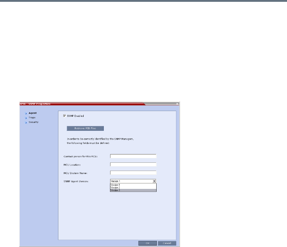
Administration and Utilities
Polycom®, Inc. 724
Defining the SNMP Parameters in the Collaboration Server
The SNMP option is enabled via the Collaboration Server Web Client application.
The addresses of the Managers monitoring the MCU and other security information are defined in the
Collaboration Server Web Client application and are saved on the MCU’s hard disk. Only users defined as
Administrator can define or modify the SNMP security parameters in the RMX Web Client application.
To enable SNMP option:
1In the RMX Web Client menu bar, select Setup > SNMP.
The RMX SNMP Properties - Agent dialog box is displayed.
This dialog box is used to define the basic information for this MCU that will be used by the SNMP
system to identify it.
2In the Agent dialog box, select the SNMP Enabled check box.
3Click Retrieve MIB Files to obtain a file that lists the MIBs that define the properties of the object
being managed.
The Retrieve MIB Files dialog box is displayed.
4Click Browse and navigate to the desired directory to save the MIB files.
5Click OK.
The path of the selected directory is displayed in the Retrieve MIB Files dialog box.
6Click Save.
The MIB files are saved to the selected directory.
7Click Close to exit the Retrieve MIB Files dialog box.
8In the Agent dialog box, define the parameters that allow the SNMP Management System and its
user to easily identify the MCU.
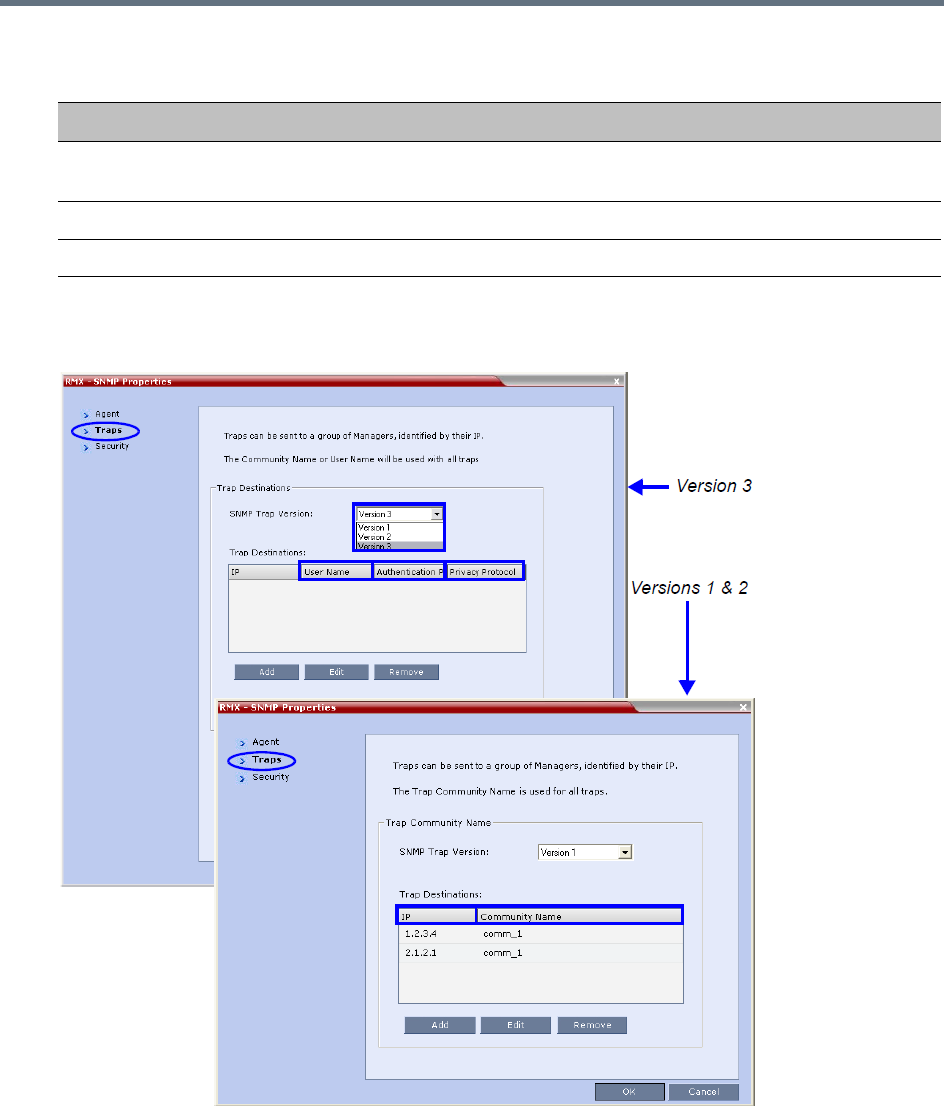
Administration and Utilities
Polycom®, Inc. 725
9Select the Traps tab.
The SNMP Properties – Traps dialog box opens.
Traps are messages sent by the MCU to the SNMP Managers when events such as MCU Startup or
Shutdown occur. Traps may be sent to several SNMP Managers whose IP addresses are specified
in the Trap Destinations box.
Collaboration Server-SNMP Properties - Agent Options
Field Description
Contact person for
this MCU
Type the name of the person to be contacted in the event of problems with the
MCU.
MCU Location Type the location of the MCU (address or any description).
MCU System Name Type the MCU’s system name.
Administration and Utilities
Polycom®, Inc. 726
10 Define the following parameters:
SNMPv3 - Traps
Field Description
SNMP Trap Version Specifies the version, either Version 1 2 or 3 of the traps being sent to the IP
Host. Polycom software supports the standard SNMP version 1 and 2 traps,
which are taken from RFC 1215, convention for defining traps for use with
SNMP.
Note: The SNMP Trap Version parameters must be defined identically in the
external SNMP application.
Trap Destination This box lists the currently defined IP addresses of the Manager terminals to
which the message (trap) is sent.
IP Enter the IP address of the SNMP trap
recipient.
All Versions
Community Name Enter the Community Name of the
manager terminal used to monitor the
MCU activity
Version 1
and Version
2
User Name Enter the name of the user who is to have
access to the trap.
Version 3
Authentication
Protocol
Enter the authentication protocol: MD5 or
SHA.
Privacy Protocol Enter the privacy protocol: DES or AES.
Engine ID Enter an Engine ID to be used for both
the Agent and the Trap.
Default: Empty
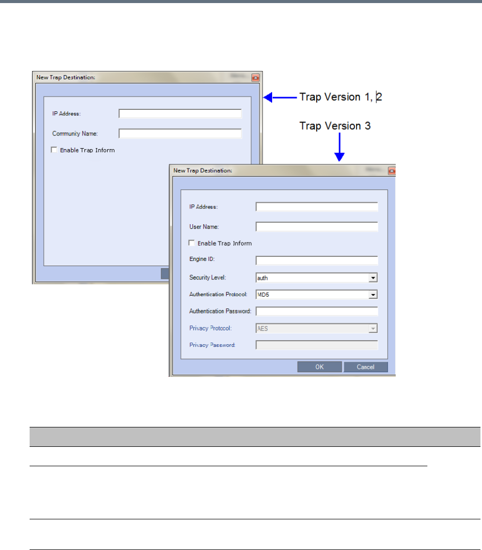
Administration and Utilities
Polycom®, Inc. 727
11 Click Add to add a new Manager terminal.
Depending on the SNMP Trap Version selected, one of the two following New Trap Destination
dialog boxes opens.
12 Define the following parameters:
SNMPv3 - Traps
Field Description Version
IP Address Enter the IP address of the SNMP trap recipient. 1,2,3
Enable Trap
Inform
An Inform is a Trap that requires receipt confirmation from the entity
receiving the Trap. If the Engine ID field (Version 3) is empty when
Enable Trap Inform has been selected, the Engine ID is set by the
Client.
Community Name Enter the Community Name of the manager terminal used to monitor the
MCU activity
1, 2

Administration and Utilities
Polycom®, Inc. 728
13 Type the IP Address and the Community name of the manager terminal used to monitor the MCU
activity, and then click OK.
The Community name is a string of characters that will be added to the message that is sent to the
external Manager terminals. This string is used to identify the message source by the external
Manager terminal.
The new IP Address and Community name is added to the Trap Destinations box.
aTo delete the IP Address of a Manager terminal, select the address you wish to delete, and click
Remove.
The IP address in the Trap Destinations box is removed.
User Name Enter the name of the user who is to have access to the trap. 3
Engine ID Enter an Engine ID to be used for the Trap.
This field is enabled when the Enable Trap Inform check box is selected.
If the Enable Trap Inform check box is cleared the Engine ID of the
Agent is used. The Engine ID is comprised of up to 64 Hexadecimal
characters.
Default: Empty
Security Level Select a Security Level from the drop-down menu.
Range: No Auth, No Priv; Auth, No Priv; Auth, Priv
Default: Auth, Priv
Authentication
Protocol
Enter the authentication protocol: MD5 or SHA.
The availability of the MD5 Authentication Protocol as a selectable option
is controlled by adding the SNMP_FIPS_MODE System Flag to
system.cfg and setting its value. A value of YES means that MD5 will
neither be displayed as selectable option nor supported.
Range: YES/NO.
Default: NO.
Authentication Password
Privacy Protocol Enter the privacy protocol: DES or AES.
The availability of the DES Privacy Protocol as a selectable option is
controlled by adding the SNMP_FIPS_MODE System Flag to system.cfg
and setting its value. A value of YES means that DES will neither be
displayed as a selectable option nor supported.
Range: YES/NO.
Default: NO.
Privacy Password
SNMPv3 - Traps
Field Description Version
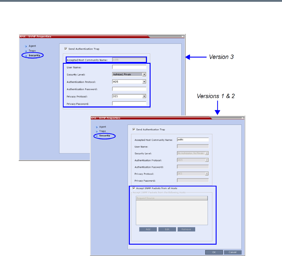
Administration and Utilities
Polycom®, Inc. 729
14 Select the Security tab.
The SNMP Properties – Security dialog box opens.
This dialog box is used to define whether the query sent to the MCU is sent from an authorized
source. When the Accept SNMP packets from all Hosts is disabled, a valid query must contain the
appropriate community string and must be sent from one of the Manager terminals whose IP address
is listed in this dialog box.

Administration and Utilities
Polycom®, Inc. 730
15 Define the following parameters:
SNMP - Security
Field Description
Send Authentication
Trap
Select this check box to send a message to the SNMP Manager
when an unauthorized query is sent to the MCU. When cleared, no
indication will be sent to the SNMP Manager.
Versions
1 & 2
Accept Host Community
Name
Enter the string added to queries that are sent from the SNMP
Manager to indicate that they were sent from an authorized source.
Note: Queries sent with different strings will be regarded as a
violation of security, and, if the Send Authentication Trap check box is
selected, an appropriate message will be sent to the SNMP Manager.
Accept SNMP Packets
from all Host
Select this option if a query sent from any Manager terminal is valid.
When selected, the Accept SNMP Packets from These Hosts option
is disabled.
Accept SNMP Packets
from the following Hosts
Lists specific Manager terminals whose queries will be considered as
valid. This option is enabled when the Accept SNMP Packets from
any Host option is cleared.
User Name Enter a User Name of up to 48 characters
Default: Empty
Version3
Security Level Select a Security Level from the drop-down menu.
Range: No Auth, No Priv; Auth, No Priv; Auth, Priv
Default: Auth, Priv
Authentication Protocol Select the authentication protocol
Range: MD5, SHA
Default: MD5
These fields are
enabled if
Authentication
is selected in the
Security Level
field.
Authentication
Password
Enter an Authentication Password.
Range: 8 - 48 characters
Default: Empty
Privacy Protocol Select a Privacy Protocol.
Range: DES, AES
Default: DES These fields are
enabled if
Privacy is
selected in the
Security Level
field.
Privacy Password Enter a Privacy Password.
Range: 8 - 48 characters
Default: Empty
Engine ID Enter an Engine ID to be used for both the Agent
and the Trap.
Default: Empty
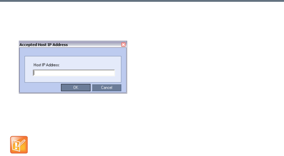
Administration and Utilities
Polycom®, Inc. 731
16 To specifically define one or more valid terminals, ensure that the Accept SNMP Packets from any
Host option is cleared, and click Add.
The Accepted Host IP Address dialog box opens.
17 Enter the IP Address of the Manager terminal from which valid queries may be sent to the MCU, and
then click OK.
Click Add to define additional IP Addresses.
The IP Address or Addresses are displayed in the Accept SNMP Packets from These Hosts box.
18 In the SNMP Properties - Security dialog box, click OK.
Audible Alarms
In addition to the visual cues used to detect events occurring on the Collaboration Server, an audible alarm
can be activated and played when participants request Operator Assistance.
Using Audible Alarms
The Audible Alarm functionality for Operator Assistance requests is enabled for each MCU in either the
Collaboration Server Web Client or RMX Manager.
The Audible Alarm played when Operator Assistance is requested is enabled and selected in the Setup >
Audible Alarm > User Customization.
When the Audible Alarm is activated, the *.wav file selected in the User Customization is played, and it is
repeated according to the number of repetitions defined in the User Customization.
If more than one Collaboration Server is monitored in the RMX Manager, the Audible Alarm must be enabled
separately for each Collaboration Server installed in the site/configuration. A different *.wav file can be
selected for each MCU.
When multiple Audible Alarms are activated in different conferences or by multiple MCUs, the Audible
Alarms are synchronized and played one after the other. It is important to note that when Stop Repeating
Alarm is selected from the toolbar from the Collaboration Server Web Client or RMX Manager, all activated
Audible Alarms are immediately halted.
Queries sent from terminals not listed in the Accept SNMP Packets from These Hosts box are
regarded as a violation of the MCU security, and if the Send Authentication Trap check box is
selected, an appropriate message will be sent to all the terminals listed in the SNMP Properties –
Traps dialog box.
Administration and Utilities
Polycom®, Inc. 732
Audible Alarm Permissions
An operator/administrator can configure the Request Operator Assistance audible alarm, however Users
with different authorization level have different configuration capabilities as shown in the following table.
Stop Repeating Message
The Collaboration Server User can stop playing the audible alarm at any time. If more than one audible
alarm has been activated, all activated alarms are immediately stopped.
If after stopping the Audible Alarms a new Operator Assistance request event occurs, the audible alarm is
re-activated.
To stop the Audible Alarm on the Collaboration Server Client or RMX Manager:
»On the Collaboration Server menu, select Setup > Audible Alarms > Stop Repeating Alarm.
When selected all audible alarms are immediately stopped.
Configuring the Audible Alarms
User Customization
The operators and administrators can:
●Enable/Disable the Audible Alarm.
●Select whether to repeat the Audible Alarm.
●Define the number of repetitions and the interval between the repetitions.
To Customize the Audio Alert on the Collaboration Server Client or RMX Manager:
1On the Collaboration Server menu, select Setup > Audible Alarms > User Customization.
The User Customization window opens.
Audible Alarm Permissions
Option Operator Administrator
User Customization Yes Yes
Download Audible Alarm File No Yes
Stop Repeating Alarms Yes Yes
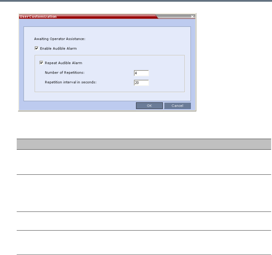
Administration and Utilities
Polycom®, Inc. 733
2Define the following parameters:
3Click OK.
Replacing the Audible Alarm File
Each Collaboration Server is shipped with a default tone file in *.wav format that plays a specific tone when
participants request Operator Assistance. This file can be replaced by a *.wav file with your own recording.
The file must be in *.wav format and its length cannot exceed one hour.
Only the User with Administrator permission can download the Audible Alarm file.
Audible Alarm - User Customization Options
Option Description
Enable Audible Alarm Select this check box to enable the Audible Alarm feature and to define its
properties.
When this check box is cleared, the Audible Alarm functionality is disabled.
Repeat Audible Alarm Select this check box to play the Audible Alarm repeatedly. When selected, it
enables the definition of the number of repetitions and the interval between
repetitions.
When cleared, the Audible Alarm will not be repeated and will be played only
once.
Number of Repetitions Define the number of times the audible alarm will be played.
Default number of repetitions is 4.
Repetition interval in
seconds
Define the number of seconds that the system will wait before playing the
Audible Alarm again.
Default interval is 20 seconds.
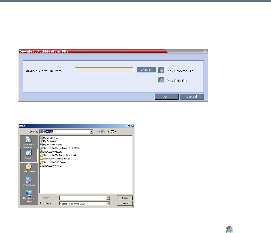
Administration and Utilities
Polycom®, Inc. 734
To replace the Audio file on the Collaboration Server Client or RMX Manager:
1On the Collaboration Server menu, select Setup > Audible Alarms > Download Audible Alarm
File.
The Download Audible Alarm File window opens.
2Click Browse to select the audio file (*.wav) to download.
The Open dialog box opens.
3Select the appropriate *.wav file, and click Open.
The selected file name is displayed in the Install Audible Alarm File dialog box.
4 Optional. You can play the selected file or the currently used file by clicking Play () as follows:
aClick Play Selected File to play a file saved on your computer.
bClick Play Collaboration Server File to play the file currently saved on the Collaboration Server.
5In the Download Audible Alarm File dialog box, click OK to download the file to the MCU.
The new file replaces the file stored on the MCU. If multiple Collaboration Servers are configured in the RMX
Manager, the file must be downloaded to each of the required MCUs separately.
Multilingual Setting
Each supported language is represented by a country flag in the Welcome Screen and can be selected as
the language for the Collaboration Server Web Client.
Customizing the Multilingual Setting
The languages available for selection in the Login screen of the RMX Web Client can be modified using the
Multilingual Setting option.
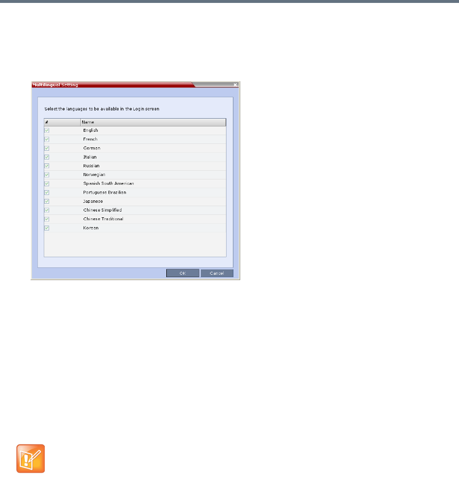
Administration and Utilities
Polycom®, Inc. 735
To customize the Multilingual Setting:
1On the Collaboration Server menu, select Setup > Customize Display Settings > Multilingual
Setting.
The Multilingual Setting dialog box is displayed.
2Select the check boxes of the languages to be available for selection.
3Click OK.
4Log out from the RMX Web Client and re-log in for the customization to take effect.
Banner Display and Customization
The Login Screen and Main Screen of the Collaboration Server Web Client and the RMX Manager can
display informative or warning text banners. These banners can include general information or they can be
cautioning users to the terms and conditions under which they may log into and access the system, as
required in many secured environments.
Banner display is enabled in the Setup > Customize Display Settings > Banners Configuration.
The administrator can choose one of four alternative login banners to be displayed. The four alternative
banners cannot be modified. A Custom banner (default) can also be defined.
The Main Page Banner is blank and can be defined.
When the ULTRA_SECURE_MODE System Flag is set to YES, the banners are displayed by
default and cannot be disabled. When set to NO (default), banner display is according to the check
box selection in the Banners Configuration dialog box.
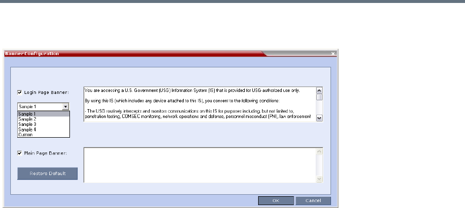
Administration and Utilities
Polycom®, Inc. 736
The Banner Configuration dialog box allows the administrator to select a Login Banner from a drop-down
menu.
One of the following Login Banners can be selected:
●Non-Modifiable Banners
Sample 1
Sample 2
Sample 3
Sample 4
●Modifiable Banner
Custom (Default)
Guidelines
●The Login Banner cannot be disabled when the Collaboration Server is in Ultra Secure Mode.
●The Login Banner must be acknowledged before the user is permitted to log in to the system.
●If a Custom banner has been created, and the user selects one of the alternative, non-modifiable
banners the Custom banner not deleted.
●The Custom Login Banner may contain up to 1300 characters.
●An empty Login Banner is not allowed.
●Any attempt to modify a non-modifiable banner results in it automatically being copied to the Custom
banner.
Non-Modifiable Banner Text
Sample 1 Banner
You are accessing a U.S. Government (USG) Information System (IS) that is provided
for USG-authorized use only.
By using this IS (which includes any device attached to this IS), you consent to the
following conditions:

Administration and Utilities
Polycom®, Inc. 737
− The USG routinely intercepts and monitors communications on this IS for purposes
including, but not limited to, penetration testing, COMSEC monitoring, network
operations and defense, personnel misconduct (PM), law enforcement (LE), and
counterintelligence (CI) investigations.
− At any time, the USG may inspect and seize data stored on this IS.
− Communications using, or data stored on, this IS are not private, are subject to
routine monitoring, interception, and search, and may be disclosed or used for any
USG authorized purpose.
− This IS includes security measures (e.g., authentication and access controls) to
protect USG interests--not for your personal benefit or privacy.
− Notwithstanding the above, using this IS does not constitute consent to PM, LE or
CI investigative searching or monitoring of the content of privileged communications,
or work product, related to personal representation or services by attorneys,
psychotherapists, or clergy, and their assistants. Such communications and work
product are private and confidential. See User Agreement for details.
Sample 2 Banner
This system is for the use of authorized users only. Individuals using this computer
system without authority, or in excess of their authority, are subject to having all
of their activities on this system monitored and recorded by systems personnel. In
the course of monitoring individuals improperly using this system, or in the course
of system maintenance, the activities of authorized users also may be monitored.
Anyone using this system expressly consents to such monitoring and is advised that if
such monitoring reveals possible criminal activity, system personnel may provide the
evidence of such monitoring to law enforcement officials.
Sample 3 Banner
You are about to access a system that is intended for authorized users only. You
should have no expectation of privacy in your use of this system. Use of this system
constitutes consent to monitoring, retrieval, and disclosure of any information
stored within the system for any purpose including criminal prosecution.
Sample 4 Banner
This computer system including all related equipment, network devices (specifically
including Internet access), is provided only for authorized use. All computer systems
may be monitored for all lawful purposes, including ensuring that their use is
authorized, for management of the system, to facilitate protection against
unauthorized access, and to verify security procedures, survivability and operational
security. Monitoring includes active attacks by authorized personnel and their
entities to test or verify the security of the system. During monitoring, information
may be examined, recorded, copied and used for authorized purposes. All information
including personal information, placed on or sent over this system may be monitored.
Use of this system, authorized or unauthorized, constitutes consent to monitoring of
this system. Unauthorized use may subject you to criminal prosecution. Evidence of
any such unauthorized use collected during monitoring may be used for administrative,
criminal or other adverse action. Use of this system constitutes consent to
monitoring for these purposes.
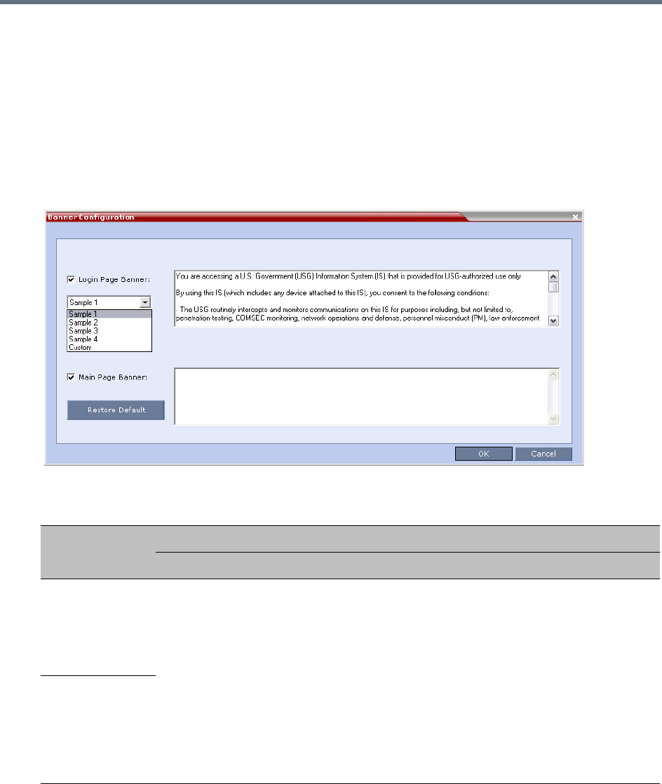
Administration and Utilities
Polycom®, Inc. 738
Customizing Banners
The Login and Main Screen banners can be customized to display conference information, assistance
information or warning text as required in the Ultra Secure Mode.
To customize the banners:
1In the Collaboration Server menu, select Setup > Customize Display Settings > Banners
Configuration.
The Banners Configuration dialog box opens.
2Customize the banners by modifying the following fields:
3Click OK.
Banner Configuration
Field
Description
Check Box Text Field Restore Default Button
Login Page
Banner Select or clear the
check box to enable or
disable the display of
the banner.
Note: Banner display
cannot be disabled in
when the
ULTRA_SECURE_M
ODE flag is set to
YES.
Edit the text in this field to meet
local requirements:
•Banner content is multilingual
and uses Unicode, UTF-8
encoding. All text and special
characters can be used.
•Maximum banner size is
100KB.
•The banner may not be left
blank when the
ULTRA_SECURE_MODE flag
is set to YES.
Click the button to
restore the default text to
the banner
Main Page
Banner
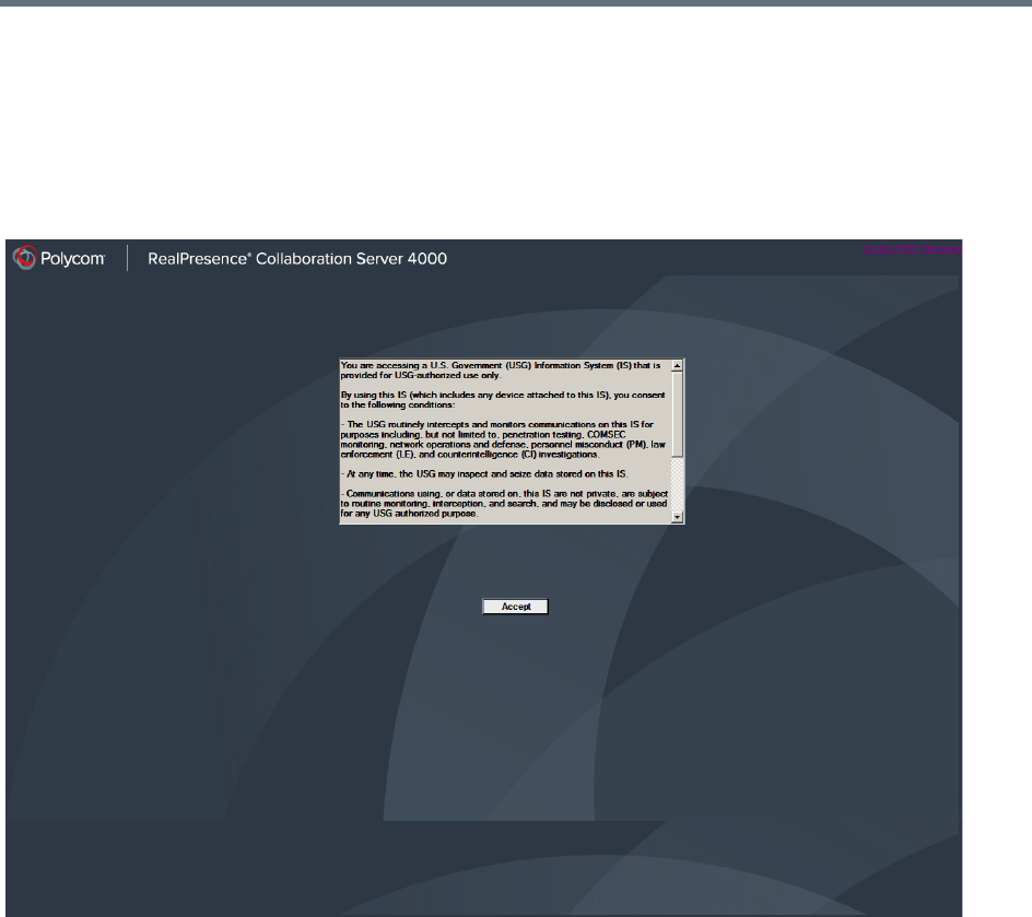
Administration and Utilities
Polycom®, Inc. 739
Banner Display
Login Screen Banner
The Login screen banner can display any text, for example the terms and conditions for system usage. The
default text is that required in Ultra Secure Mode. The user must acknowledge that the information was read
and click Accept to proceed to the Login screen as shown in the following screen:
When the Collaboration Server is configured to work in Ultra Secure Mode, such as Maximum Security
Environments, the display banner includes the terms and conditions for system usage as detailed in the
default text: contained in Sample Banner 1.
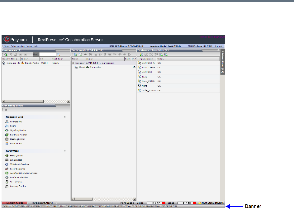
Administration and Utilities
Polycom®, Inc. 740
Main Screen Banner
The Main Screen banner is displayed at the bottom of the screen:
When the Collaboration Server is configured to work in Ultra Secure Mode, such as the Maximum Security
environment, the display banner includes the following default text:
THIS IS A DOD SYSTEM AND IS SUBJECT TO MONITORING, UNAUTHORIZED USE MAY SUBJECT YOU
TO ADMINISTRATIVE ACTION OR CRIMINAL PROSECUTION AND PENALTIES.

Administration and Utilities
Polycom®, Inc. 741
Software Management
The Software Management menu is used to backup and restore the Collaboration Server's configuration
files and to download MCU software.
Backup and Restore Guidelines
●Direct access to the Collaboration Server file system is disabled in both Ultra Secure Mode and
standard security mode.
●System Backup can only be performed by an administrator.
●The System Backup procedure creates a single backup file that can be viewed or modified only by
developers.
●A System Backup file from one system can be restored on another system.
●To ensure file system consistency, do not perform any configuration changes as the system does not
suspended them during the backup procedure.
●The following parameters, settings and files are backed up:
MCMS configuration files (/mcms/Cfg):
Network and service configurations,
Rooms,
Profiles
Reservations
System Flags
Resource Allocation
IVR messages, music
Collaboration Server Web Client user setting - fonts, windows
Collaboration Server Web Client global settings – notes, address book, language
Private keys and certificates (TLS)
Conference participant settings
Operation DB (administrator list)
SNMP settings
Time configuration
●CDR files are not included in the backup process and should be backed up manually by saving the
CDR files to a destination device.
This applies only to one RealPresence Collaboration Server (RMX) 1500/1800/2000/4000 system to
another. Do not use a backup file from the RealPresence Collaboration Server (RMX)
1500/1800/2000/4000 on any other model.
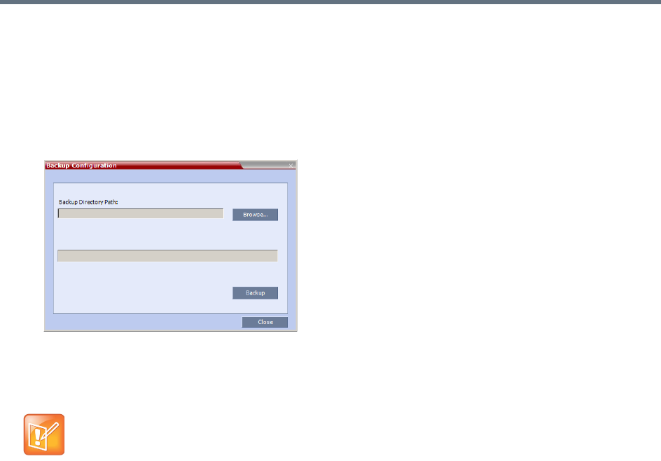
Administration and Utilities
Polycom®, Inc. 742
Using Software Management
To backup configuration files:
1On the Collaboration Server menu, select Administration > Software Management > Backup
Configuration.
The Backup Configuration dialog box opens.
2Click Browse.
The Browse To File dialog box opens.
3Select the Backup Directory Path and then click Backup.
To restore configuration files:
1On the Collaboration Server menu, select Administration > Software Management > Restore
Configuration.
2Browse to the Restore Directory Path where the backed up configuration files are stored and then
click Restore.
To download MCU software files:
1On the Collaboration Server menu, select Administration > Software Management > Software
Download.
2Browse to the Install Path and then click Install.
When the Collaboration Server system backs up the current configuration, if any changes occur
immediately or during the request, then additional changes are not registered.
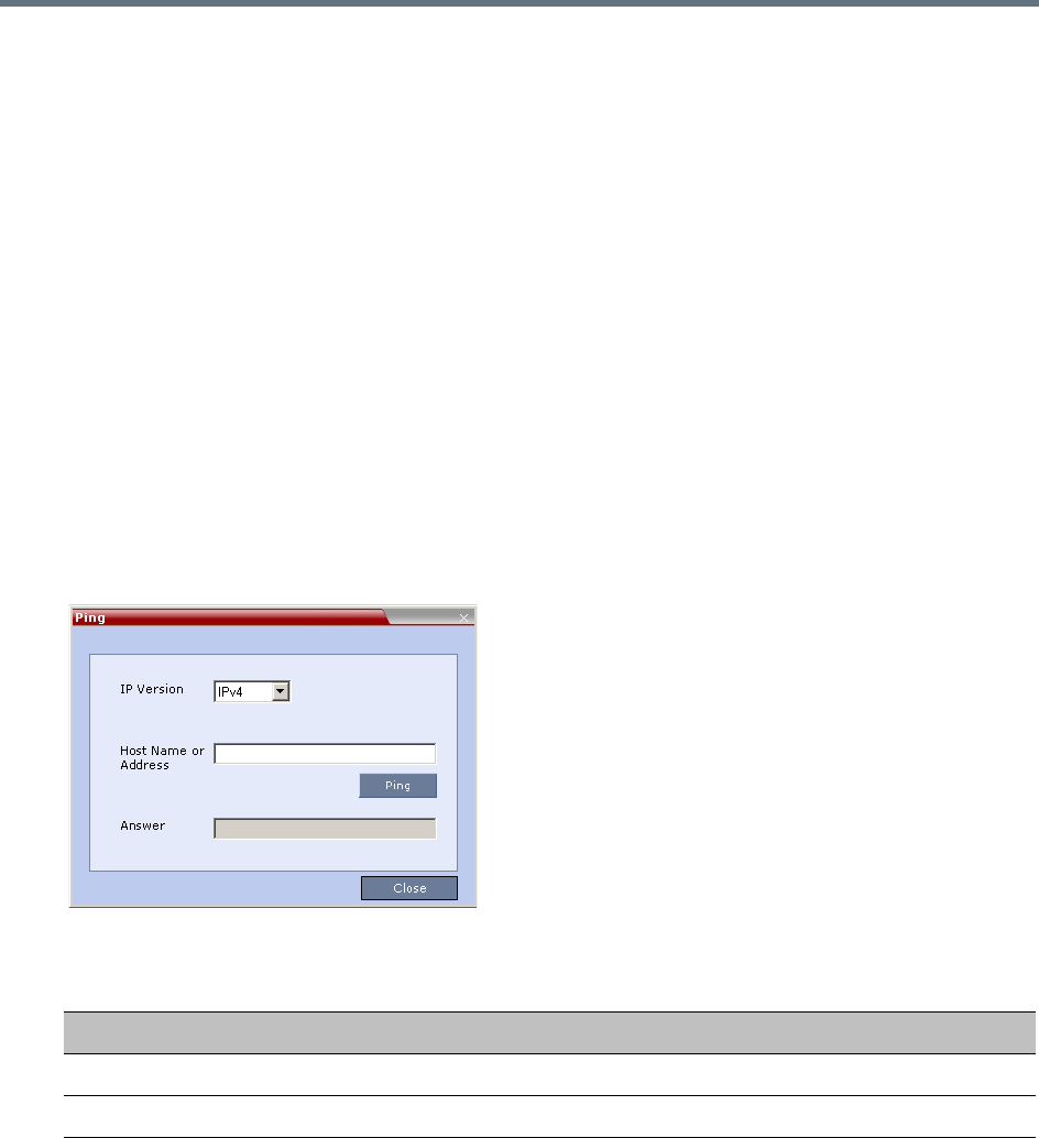
Administration and Utilities
Polycom®, Inc. 743
Ping the Collaboration Server
The Ping administration tool enables the Collaboration Server Signaling Host to test network connectivity
by Pinging IP addresses.
Guidelines
●The IP addressing mode can be either IPv4 or IPv6.
●Both explicit IP addresses and Host Names are supported.
●The Collaboration Server Web Client blocks any attempt to issue another Ping command before the
current Ping command has completed. Multiple Ping commands issued simultaneously from multiple
Collaboration Server Web Clients are also blocked.
Using Ping
To Ping a network entity from the Collaboration Server:
1On the Collaboration Server menu, select Administration > Tools > Ping.
The Ping dialog box is displayed:
2Modify or complete the following fields:
3Click Ping.
The Ping request is sent to the Host Name or IP Address of the Collaboration Server entity.
The Answer is either:
OK
or
FAILED
Ping Parameters
Field Description
IP Version Select IPv4 or IPv6 from the drop-down menu.
Host Name or Address Enter the Host Name or IP Address of the network entity to be Pinged.
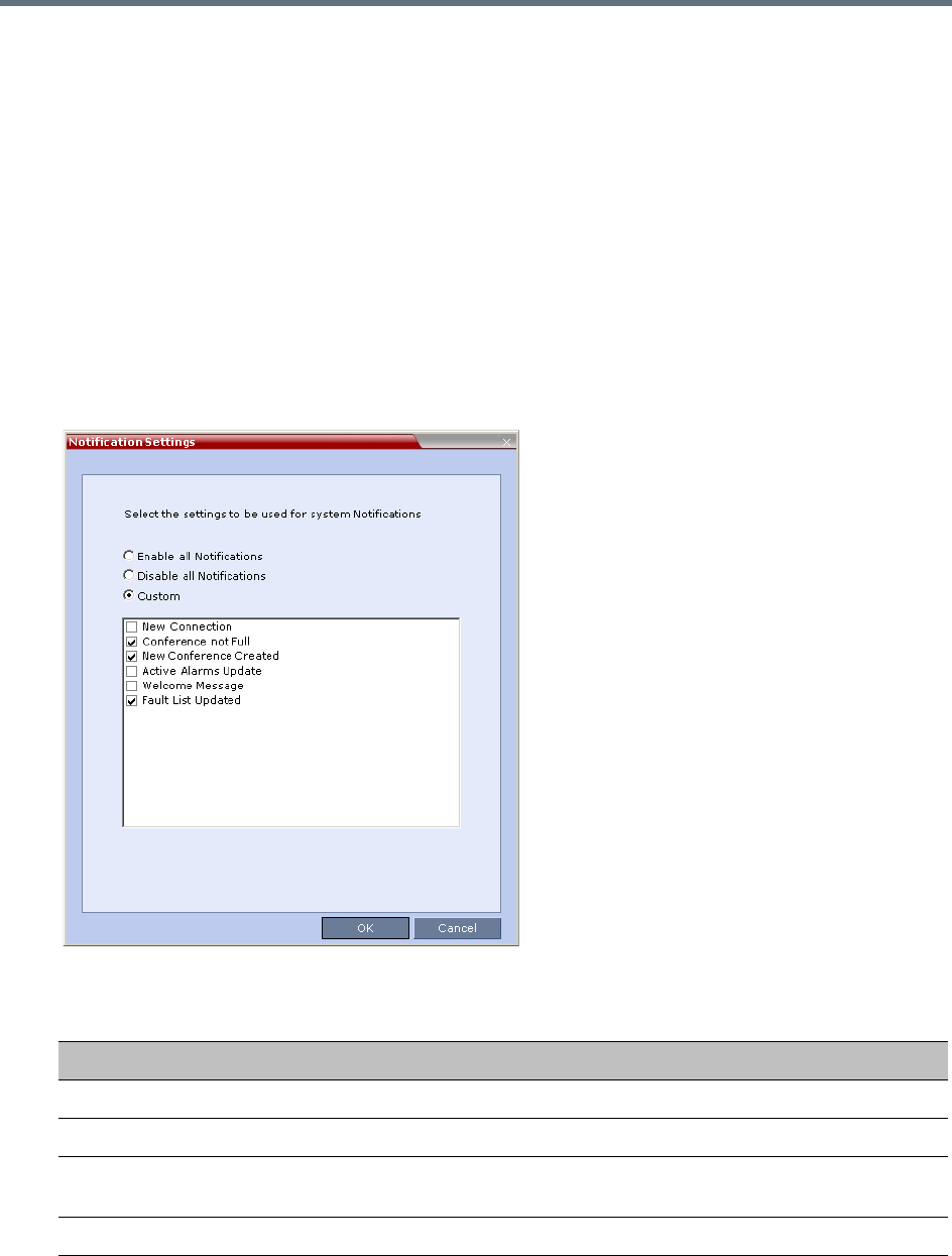
Administration and Utilities
Polycom®, Inc. 744
Notification Settings
The Collaboration Server can display notifications when:
●A new Collaboration Server user connects to the MCU.
●A new conference is started.
●Not all defined participants are connected to the conference or when a single participant is connected.
●A change in the MCU status occurs and an alarm is added to the alarms list.
A welcome message is displayed to the Collaboration Server user upon connection.
To configure the notifications:
1On the Collaboration Server menu, select Setup > Notification Settings.
The Notification Settings dialog box is displayed.
The following notification options are displayed.
Notification Settings Parameters
Field Description
New Connection Notification of a new user/administrator connecting to the Collaboration Server.
New Conference Created New conference has been created.
Conference Not Full The conference is not full and additional participants are defined for the
conference.
Welcome Message A welcome message after user/administrator logon.
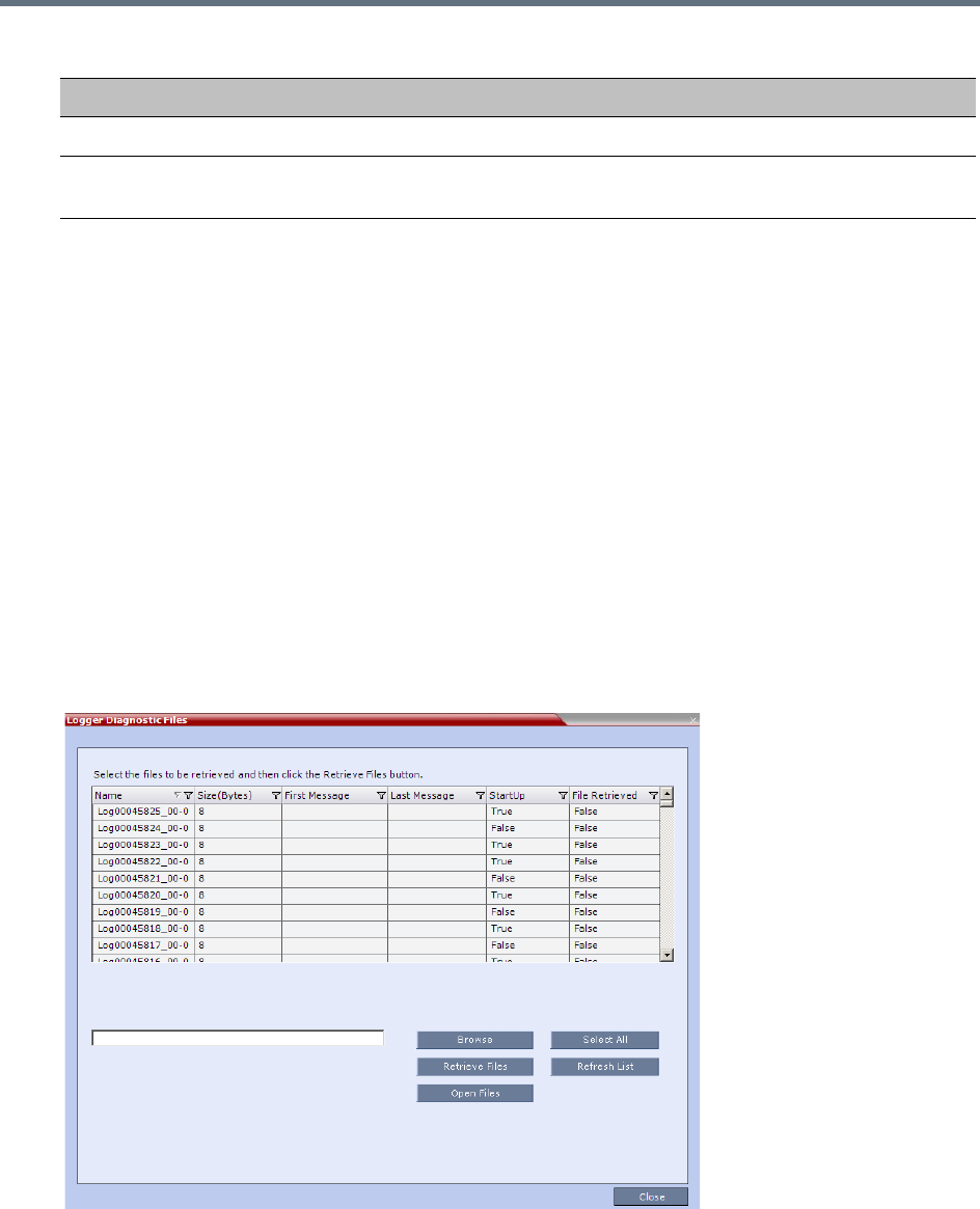
Administration and Utilities
Polycom®, Inc. 745
2Enable/Disable All Notifications or Custom to select specific notifications to display.
3Click OK.
Logger Diagnostic Files
The Logger utility is a troubleshooting tool that continually records MCU system messages and saves them
to files in the MCU hard drive. For each time interval defined in the system, a different data file is created.
The files may be retrieved from the hard drive for off-line analysis and debugging purposes.
The Logger utility is activated at the MCU startup. The Logger is disabled when the MCU is reset manually
or when there is a problem with the Logger utility, e.g. errors on the hard drive where files are saved. In such
cases, data cannot be retrieved.
When the MCU is reset via the Collaboration Server, the files are saved on the MCU hard drive.
To access the Logger Diagnostic Files:
»On the Collaboration Server menu, select Administration > Tools > Logger Diagnostic Files.
The following tasks can be performed:
Active Alarms Update Updates you of any new alarm that occurred.
Fault List Updated Updates you when the faults list is updated (new faults are added or existing
faults are removed).
Notification Settings Parameters
Field Description
Administration and Utilities
Polycom®, Inc. 746
When retrieved, the log file name structure is as follows:
●Sequence number (starting with 1)
●Date and Time of first message
●Date and Time of last message
●File size
●Special information about the data, such as Startup
File name structure:
Log_SNxxxxxxxxxx_FMDddmmyyy_FMThhmm_LMDddmmyyyy_LMThhmm_SZxxxxxxxxxx_SUY.log
File name format:
●SN = Sequence Number
●FM = First Message, date and time
●LM = Last Message, date and time
●SZ = Size
●SU = Startup (Y/N) during the log file duration
Example:
Log_SN0000000002_FMD06032007_FMT083933_LMD06032007_LMT084356_SZ184951_SUY.log.
To Retrieve the Logger Files:
1Select the log files to retrieve. Multiple selections of files are enabled using standard Windows
conventions.
2In the Logger Diagnostic Files dialog box, click Browse.
3In the Browse for Folder window, select the directory location to save the Logger files and click OK.
You will return to the Logger Diagnostic Files dialog box.
Diagnostic File Button Options
Button Description
Refresh List Refreshes the list and adds newly generated logger files.
Select All Selects all the logger files listed.
Browse Selects the destination folder for download.
Retrieve Files Saves files to the destination folder.
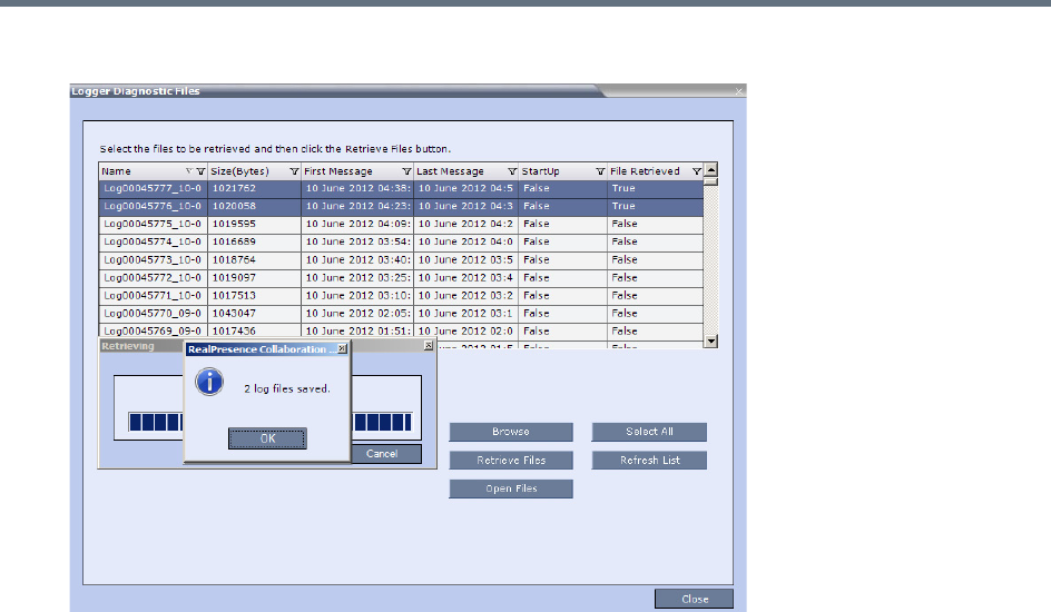
Administration and Utilities
Polycom®, Inc. 747
4Click Retrieve Files.
The log files (in *.txt format) are saved to the defined directory and a confirmation caption box is
displayed indicating a successful retrieval of the log files.
To View the Logger Files:
To analyze the log files generated by the system, open the retrieved *.txt files in any text editor application,
i.e. Notepad, Textpad or MS Word.
1Using Windows Explorer, browse to the directory containing the retrieved log files.
2Use any text editor application to open the log file(s).
Information Collector
Standard Security Mode
The Information Collector comprehensively attains all information from all the MCU internal entities for data
analysis. That data, stored in a central repository, is logged from the following system components:
•System Log Files •Full faults
•CDR •Apache logs
•OS (Core dumps, CFG - DNS, DHCP, NTP, kernal state,
event logs
•CFG directory (without IVR)
•Signaling Trace files (H.323 & SIP) •Cards info: HW version, state and status
•Central Signaling logs •SW version number
•Processes internal state and statistics

Administration and Utilities
Polycom®, Inc. 748
The data collected is saved into a single compressed file containing all the information from each system
component in its relative format (.txt, .xml, etc.). In case the disk is malfunctioning, the file will be written to
the RAM (involves only a small amount of information where the RAM size is 1/2 a gigabyte). The zipped
file (info.tgz) can be opened with the following applications: WinRAR and WinZip. The entire zipped file is
then sent to Polycom’s Network Systems Division for analysis and troubleshooting.
Ultra Secure Mode
The Information Collector logs information from the Collaboration Server’s Network Intrusion Detection
System (NIDS), saving it into a compressed disk file. (If the disk malfunctions, the file is written to RAM.)
The zipped file (info.tgz) can be opened with either WinRAR or WinZip. The entire zipped file can be sent
to Polycom for analysis.
Network Intrusion Detection System (NIDS)
The Collaboration Server system uses iptables for access control. For each different kind of packet
processing, there is a table containing chained rules for the treatment of packets. Every network packet
arriving at or leaving from the Collaboration Server must pass the rules applicable to it.
Depending on the nature of the suspect packets, the rules may reject, drop, or limit their arrival rate
(dropping the rest).
The Collaboration Server maintains a log that includes all unpermitted access attempts blocked by the fire
wall.
Unpermitted access includes:
●Access to ports which are not opened on the Collaboration Server.
●Invalid access to open ports.
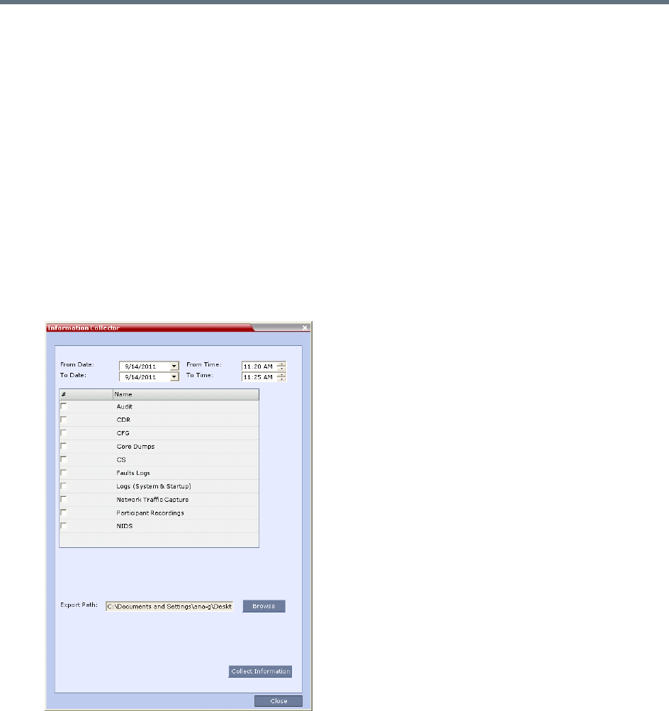
Administration and Utilities
Polycom®, Inc. 749
Using the Information Collector
When the Information Collector is used the following steps are performed:
●Step 1: Creating the Information Collector file.
●Step 2: Saving the Information Collector file.
●Step 3: Viewing the information in the Information Collector file.
Step 1: Creating the Information Collector Compressed File
To create the compressed file:
1In the Collaboration Server menu, select Administration > Tools > Information Collector.
The Information Collector dialog box is displayed.
Information Collector - Standard Security Mode
Information Collector - Ultra Secure Mode
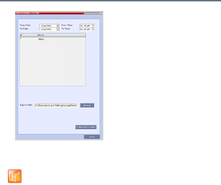
Administration and Utilities
Polycom®, Inc. 750
2In the From Date and Until Date fields, use the arrow keys to define the date range of the data files
to be included in the compressed file.
3In the From Time and Until Time fields, use the arrow keys to define the time range of the data files
to be included in the compressed file.
4Select the check boxes of the information to be collected.
5In the Export Path field, click Browse, and navigate to the directory path where the compressed file
is to be saved.
6Click Collect Information.
A progress indicator is displayed in the Information Collector dialog box while the file is being
created.
Step 2: Saving the Compressed File
1The compressed file is automatically saved in the directory selected in the Information Collector
dialog box. The file is named info.tgz.
A success information box is displayed.
2Click OK.
If logs are being collected in order to troubleshoot a specific issue, it is important that the date and
time range include the time and date in which the issue occurred. The default date and time ranges
may not be sufficient.
For example, if a specific issue occurred on October 1, 2013 at 12:15, the From Date and Until
Date should be October 1, 2013, the From Time should be around 12:10, and the Until Time
should be around 12:20.

Administration and Utilities
Polycom®, Inc. 751
Step 3: Viewing the Compressed File
The compressed file is saved in .tgz format and can be viewed with any utility that can open files of that
format, for example WinRAR® 3.80.
To view the compressed file:
1Navigate to the directory on the workstation in which the file was saved.
2Double click the info.tgz file to view the downloaded information.
Auditor
An Auditor is a user who can view Auditor and CDR files for system auditing purposes.
The Event Auditor enables administrators and auditors to analyze configuration changes and unusual or
malicious activities in the Collaboration Server system.
Auditor operates in real time, recording all administration activities and login attempts from the following
Collaboration Server modules:
●Control Unit
●Shelf Manager
For a full list of monitored activities, see Audit Events.
The Auditor must always be active in the system. A System Alert is displayed if it becomes inactive for any
reason.
The Auditor tool is composed of the Auditor Files and the Auditor File Viewer that enables you to view the
Auditor Files.
Auditor Files
All audit events are saved to a buffer file on hard disk in real time and then written to a file on hard disk in
XML in an uncompressed format.
A new current auditor event file is created when:
●The system is started
●The size of the current auditor event file exceeds 2 MB
Some browsers save the file as info.gz due to a browser bug. If this occurs, the file must be
manually renamed to info.tgz before it can be viewed.
The Auditor user must connect to the Collaboration Server using the RMX Web Client only.
Time stamps of Audit Events are GMT.
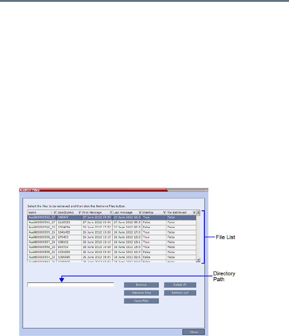
Administration and Utilities
Polycom®, Inc. 752
●The current auditor event file’s age exceeds 24 hours
Up to 1000 auditor event files are stored per Collaboration Server. These files are retained for at least one
year and require 1.05 GB of disk space. The files are automatically deleted by the system (oldest first) when
the system reaches the auditor event file limit of 1000.
A System Alert is displayed with Can't store data displayed in its Description field if:
●the system cannot store 1000 files
●the Collaboration Server does not have available disk space to retain files for one year
Audit Event Files are retained by the Collaboration Server for at least 1 year. Any attempt to delete an audit
event file that is less than one year old raises a System Alert with File was removed listed in the Description
field.
Using the Restore Factory Defaults of the System Restore procedure erases Audit Files.
Retrieving Auditor Files
You can open the Auditor file directly from the Auditor Files list or you can retrieve the files and save them
to a local workstation.
To access Auditor Files:
»On the Collaboration Server menu, select Administration > Tools > Auditor Files.
The Auditor Files dialog box is displayed.
The Auditor Files dialogue box displays a file list containing the following file information:
Name
Size (Bytes)
First Message – Date and time of the first audit event in the file

Administration and Utilities
Polycom®, Inc. 753
Last Message – Date and time of the last audit event in the file
StartUp:
True – File was created when the system was started
False – File was created when previous audit event file reached a size of 2 MB or was more
than 24 hours old
File Retrieved:
True - File was previously retrieved.
False - File was never previously retrieved.
The order of the Auditor Files dialog box field header columns can be changed and the fields can
be filtered to enable searching.
For more information, see Auditor File Viewer.
To retrieve files for storage on a workstation:
1Click Browse, select the folder on the workstation to receive the files, and click OK.
The folder name is displayed in the directory path field.
2Select the file(s) to be retrieved by clicking their names in the file list or click Select All to retrieve all
the files. (Windows multiple selection techniques can be used.)
3Click Retrieve Files.
The selected files are copied to the selected directory on the workstation.
To open the file in the Auditor File Viewer:
»Double-click the file.
Auditor File Viewer
The Auditor File Viewer enables Auditors and Administrators to view the content of and perform detailed
analysis on auditor event data in a selected Auditor Event File.
You can view an Auditor Event File directly from the Auditor Files list or by opening the file from the Auditor
File Viewer.
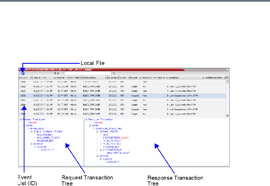
Administration and Utilities
Polycom®, Inc. 754
To open the Auditor File Viewer from the Administration Menu:
1On the Collaboration Server menu, select Administration > Tools > Auditor File Viewer.
The Auditor File Viewer is displayed.
If you previously double clicked an Auditor Event File in the Auditor Files list, that file is automatically
opened.
The following fields are displayed for each event:

Administration and Utilities
Polycom®, Inc. 755
Auditor Event Columns
Field Description
Event ID The sequence number of the event generated by the Collaboration Server.
Date & Time The date and time of the event taken from the Collaboration Server’s Local Time
setting.
User Name The Username (Login Name) of the user who triggered the event.
Reporting Module The Collaboration Server system internal module that reported the event:
•MCMS
•MPL
•Central Signaling
•MPL Simulation
•Collaboration Server Web Client
•CM Switch
•Shelf Management
•ART
•Video
•Card Manager
•RTM
•MUX
Workstation The name (alias) of the workstation used to send the request that triggered the
event.
IP Address (Workstation) The IP address of the workstation used to send the request that triggered the
event.
Event Type Auditor events can be triggered by:
•API
•HTTP
•Collaboration Server Internal Event
Event The process, action, request or transaction that was performed or rejected.
•POST:SET transactions (API)
•Configuration changes via XML (API)
•Login/Logout (API)
•GET (HTTP)
•PUT (HTTP)
•MKDIR (HTTP)
•RMDIR (HTTP)
•Startup (Collaboration Server Internal Event)
•Shutdown (Collaboration Server Internal Event)
•Reset (Collaboration Server Internal Event)
•Enter Diagnostic Mode (Collaboration Server Internal Event)
•IP address changes via USB (Collaboration Server Internal Event)

Administration and Utilities
Polycom®, Inc. 756
The order of the Auditor File Viewer field header columns can be changed and the fields can be
sorted and filtered to facilitate different analysis methods.
2In the event list, click the events or use the keyboard’s Up and Down arrow keys to display the
Request Transaction and Response Transaction XML trees for each audit event.
The transaction XML trees can be expanded and collapsed by clicking the expand ( ) and collapse
( ) buttons.
To open an auditor event file stored on the workstation:
1Click Local File ( ) to open the Open dialogue box.
2Navigate to the folder on the workstation that contains the audit event file.
3Select the audit event file to be opened.
4Click Open.
The selected file is opened in the Auditor Viewer.
Audit Events
Alerts and Faults
Alerts and Faults that are recorded by the Auditor.
Process Completed Status of the process, action, request or transaction returned by the system:
•Yes – performed by the system.
•No – rejected by the system.
Description A text string describing the process, action, request or transaction.
Additional Information An optional text string describing the process, action, request or transaction in
additional detail.
Alerts and Faults recorded by the Auditor
Event
Attempt to exceed the maximum number of management session per user
Attempt to exceed the maximum number of management sessions per system
Central Signaling indicating Recovery status.
Failed login attempt
Failed to open Apache server configuration file.
Failed to save Apache server configuration file.
Fallback version is being used.
Auditor Event Columns
Field Description

Administration and Utilities
Polycom®, Inc. 757
File system scan failure.
File system space shortage.
Internal MCU reset.
Internal System configuration during startup.
Invalid date and time.
Invalid MCU Version.
IP addresses of Signaling Host and Control Unit are the same.
IP Network Service configuration modified.
IP Network Service deleted.
Login
Logout
Management Session Time Out
MCU Reset to enable Diagnostics mode.
MCU reset.
Music file error.
New activation key was loaded.
New version was installed.
NTP synchronization failure.
Polycom default User exists.
Private version is loaded.
Restoring Factory Defaults.
Secured SIP communication failed.
Session disconnected without logout
SSH is enabled.
System Configuration modified.
System is starting.
System Resets.
TCP disconnection
Terminal initiated MCU reset.
Alerts and Faults recorded by the Auditor
Event

Administration and Utilities
Polycom®, Inc. 758
Transactions
Transactions that are recorded by the Auditor.
The Log file system is disabled.
The software contains patch(es).
USB key used to change system configuration.
User closed the browser
User initiated MCU reset.
Transactions recorded by the Auditor
Transaction
TRANS_CFG:SET_CFG
TRANS_IP_SERVICE:DEL_IP_SERVICE
TRANS_IP_SERVICE:NEW_IP_SERVICE
TRANS_IP_SERVICE:SET_DEFAULT_H323_SERVICE
TRANS_IP_SERVICE:SET_DEFAULT_SIP_SERVICE
TRANS_IP_SERVICE:UPDATE_IP_SERVICE
TRANS_IP_SERVICE:UPDATE_MANAGEMENT_NETWORK
TRANS_ISDN_PHONE:ADD_ISDN_PHONE
TRANS_ISDN_PHONE:DEL_ISDN_PHONE
TRANS_ISDN_PHONE:UPDATE_ISDN_PHONE
TRANS_ISDN_SERVICE:DEL_ISDN_SERVICE
TRANS_ISDN_SERVICE:NEW_ISDN_SERVICE
TRANS_ISDN_SERVICE:SET_DEFAULT_ISDN_SERVICE
TRANS_ISDN_SERVICE:UPDATE_ISDN_SERVICE
TRANS_MCU:BEGIN_RECEIVING_VERSION
TRANS_MCU:COLLECT_INFO
TRANS_MCU:CREATE_DIRECTORY
TRANS_MCU:FINISHED_TRANSFER_VERSION
TRANS_MCU:LOGIN
TRANS_MCU:LOGOUT
Alerts and Faults recorded by the Auditor
Event
Administration and Utilities
Polycom®, Inc. 759
ActiveX Bypass
At sites that, for security reasons, do not permit Microsoft® ActiveX® to be installed, the MSI (Windows
Installer File) utility can be used to install .NET Framework and .NET Security Settings components on
workstations throughout the network.
All workstation that connect to Collaboration Server systems must have both.NET Framework and .NET
Security Settings running locally. These components are used for communication with the Collaboration
Server and can only be installed on workstations by users with administrator privileges.
The MSI utility requires the IP addresses of all the Collaboration Server systems (both control unit and Shelf
Management IP addresses) that each workstation is to connect to.
If the IP address of the any of the target Collaboration Servers is changed, the ActiveX components must
be reinstalled.
Installing ActiveX
To install ActiveX components on all workstations in the network:
1Download the MSI file EMA.ClassLoaderInstaller.msi from the Polycom Resource Center.
The MSI file contains installation scripts for both .NET Framework and .NET Security Settings.
TRANS_MCU:REMOVE_DIRECTORY
TRANS_MCU:REMOVE_DIRECTORY_CONTENT
TRANS_MCU:RENAME
TRANS_MCU:RESET
TRANS_MCU:SET_PORT_CONFIGURATION
TRANS_MCU:SET_RESTORE_TYPE
TRANS_MCU:SET_TIME
TRANS_MCU:TURN_SSH
TRANS_MCU:UPDATE_KEY_CODE
TRANS_OPERATOR:CHANGE_PASSWORD
TRANS_OPERATOR:DELETE_OPERATOR
TRANS_OPERATOR:NEW_OPERATOR
TRANS_RTM_ISDN_SPAN:UPDATE_RTM_ISDN_SPAN
TRANS_SNMP:UPDATE
Transactions recorded by the Auditor
Transaction
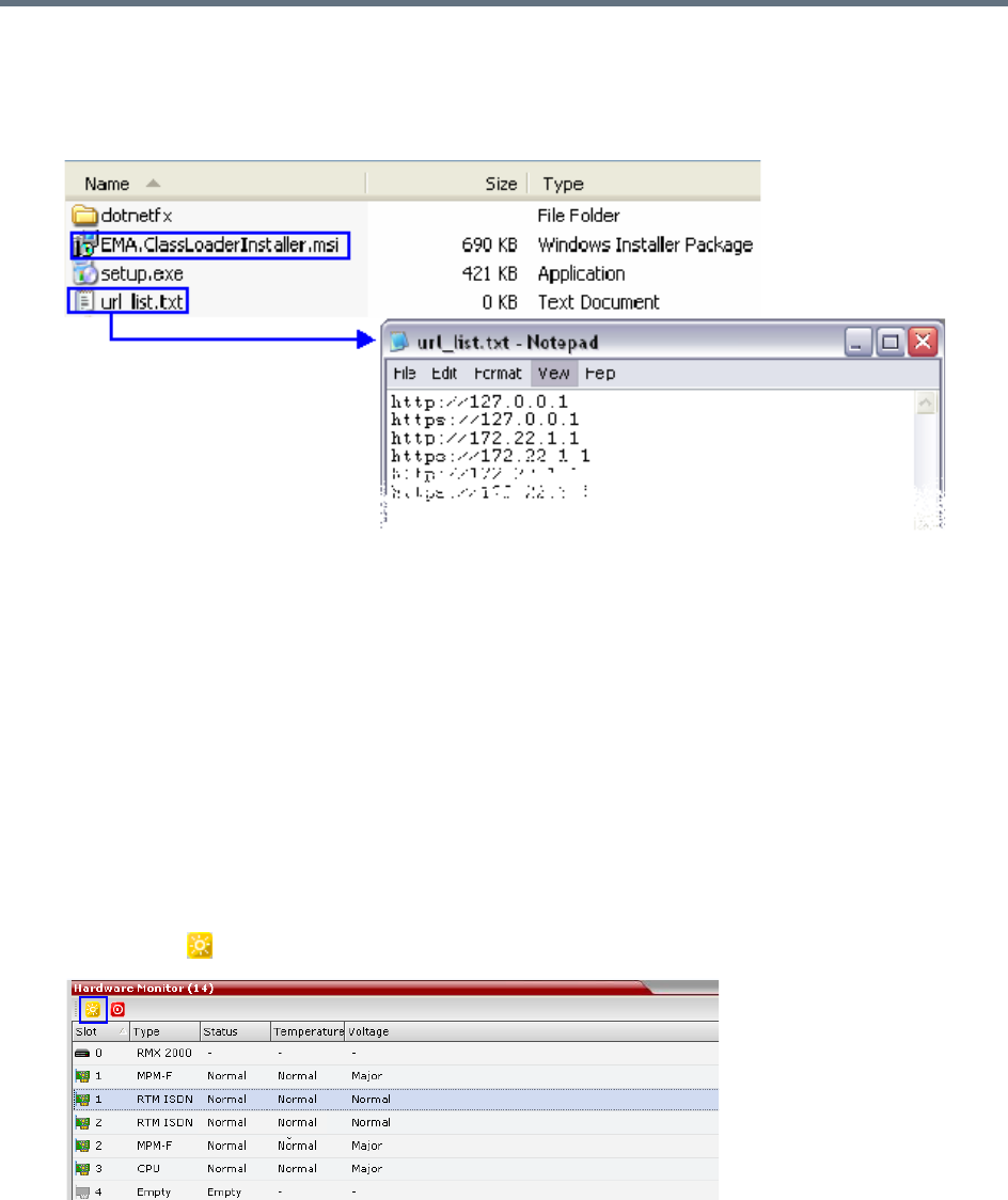
Administration and Utilities
Polycom®, Inc. 760
2Create a text file to be used during the installation containing the IP addresses of all the
Collaboration Server systems (both control unit and Shelf Management IP addresses) that each
workstation in the network is to connect to.
The file must be named url_list.txt and must be saved in the same folder as the downloaded MSI file.
3Install the ActiveX components on all workstations on the network that connect to Collaboration
Server systems.
The installation is done by the network administrator using a 3rd party network software installation
utility and is transparent to all other users.
Resetting the Collaboration Server
System Reset saves system configuration changes and restarts the system with the latest settings.
To reset the RMX:
1In the RMX Management pane, click Hardware Monitor.
The Hardware Monitor pane is displayed.
2Click Reset ().

Administration and Utilities
Polycom®, Inc. 761
When the Collaboration Server system is reset, during Collaboration Server startup the Progress Bar
appears at the bottom of the Collaboration Server Status pane, displaying the amount of time
remaining for the reset process to complete:
The Startup progress is also indicated by a green bar moving from left to right.
The duration of the Startup depends on the type of activity that preceded the MCU reset. For
example: Fast Configuration Wizard, New Version installation, Version Upgrade, Restore Last
Configuration etc.
When resetting the Collaboration Server from the Hardware Monitor, sometimes SIP endpoints may
remain connected although the conference ended.
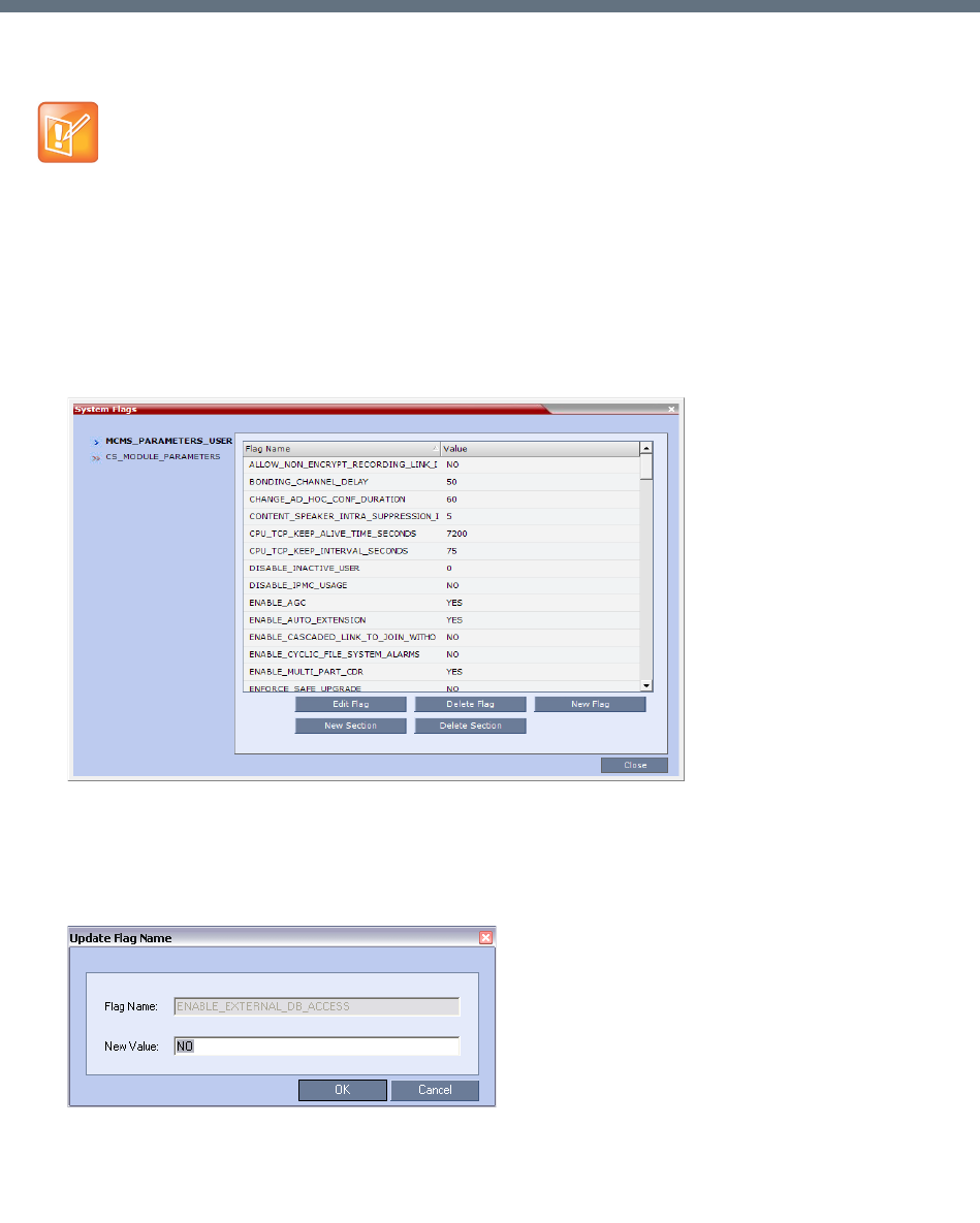
Polycom®, Inc. 762
System Configuration Flags
The system’s overall behavior can be configured by modifying the default values of the System Flags.
Modifying System Flags
To modify system flags:
1On the Collaboration Server menu, select Setup > System Configuration.
The System Flags dialog opens.
2In the MCMS_PARAMETERS_USER tab, the flags listed in the MCMS_PARAMETERS_USER
Flags table can be modified.
3To modify a flag value, select the flag and click Edit Flag, or double-click it.
4In the New Value field, enter the flag’s new value.
5Click OK to close the Update Flag dialog.
Generally, for flag changes (including deletion) to take effect, the MCU must be reset, unless
indicated otherwise.
For information on system reset see Resetting the Collaboration Server (RMX).
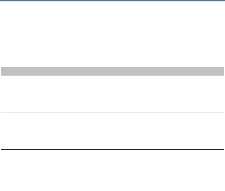
System Configuration Flags
Polycom®, Inc. 763
6Repeat steps 2–5 to modify additional flags.
7Click OK to close the System Flags dialog.
8If not otherwise indicated, reset the MCU for flag changes (including deletion) to take effect. For more
information see Resetting the Collaboration Server.
Manually Added and Deleted System Flags
MCMS_PARAMETERS_USER Flags
Flag Description
ALLOW_NON_ENCRYPT_RECOR
DING_LINK_IN_ENCRYPT_CONF
When set to NO (default), the Recording Link inherits the encryption
settings of the conference. If the conference is encrypted, the recording link
will be encrypted.
When set to YES, it disables the encryption of the recording link,
regardless of the Encryption settings of the conference and
RealPresence Capture Server or RSS 4000 system recorder.
BONDING_CHANNEL_DELAY When connecting a bonding group, this is the delay (number of 1/100
seconds) between dialing attempts to connect sequential channels.
The channel per second connection performance of ISDN switches can
vary and can cause timing issues that result in bonding channel
disconnection.
Default: 50
CHANGE_AD_HOC_CONF_DURAT
ION
The duration of an ad-hoc conference* can be configured on a system level
by setting the flag to one of the following values (in minutes): 60 (default),
90, 180 and 270.
* An ad-hoc conference is automatically created when the participant dials
into an Ad-hoc Entry Queue and enters a conference ID that is not being
used by any other conferencing entity. It is based on the Conference Profile
assigned to the EQ.
CONTENT_SLAVE_LINKS_INTRA_
SUPPRESSION_IN_ SECONDS
Defines the interval, in seconds, during which the Collaboration Server is
allowed to forward an Intra Request received from any of the Slave
Cascading Links. The Slave Cascading Link can be connected to the local
Collaboration Server, to an MCU on a higher cascade level or to the
Content sharer.
The first Intra request that is received from any of the Slave MCUs
connected to the Collaboration Server starts the interval counter and is
forwarded to the next level MCU or to the Content sharer.
All other Intra requests that are received within this interval are registered
but ignored. After an interval of <flag value> seconds, the system checks if
during the last interval any additional Intra requests were registered. If
there is at least one Intra request it will be forwarded. If there is no
additional Intra request not no action is taken other than to wait for the next
cycle.
This filtering process is repeated every <flag value> seconds.
Default: 30
System Configuration Flags
Polycom®, Inc. 764
CONTENT_SPEAKER_INTRA_SUP
PRESSION_IN_SECONDS
This flag controls the requests to refresh (intra) the content sent from the
Collaboration Server system to the content sender as a result of refresh
requests initiated by other conference participants.
Enter the interval in seconds between the Intra requests sent from the
Collaboration Server to the endpoint sending the content to refresh the
content display. Refresh requests that will be received from endpoints
within the defined interval will be postponed to the next interval.
Default setting: 5
CPU_TCP_KEEP_ALIVE_TIME_SE
CONDS
This flag indicates when to send the first KeepAlive indication to check the
TCP connection.
Default value: 7200 second (120 minutes)
Range: 600-18000 seconds
When there are NAT problems, this default may be too long and the TCP
connection is lost. In such a case, the default value should be changed to
3600 seconds (60 minutes) or less.
CPU_TCP_KEEP_INTERVAL_SEC
ONDS
This flag indicates the interval in seconds between the KeepAlive requests.
Default value: 75 second
Range: 10-720 seconds.
DISABLE_INACTIVE_USER Users can be automatically disabled by the system when they do not log
into the Collaboration Server application for a predefined period.
Possible Values: 0 - 90 days.
Default: 0 (disables this option).
Default (ULTRA_SECURE_MODE=YES): 30
ENABLE_ACCEPTING_ICMP_REDI
RECT
When set to YES, allows the RMX to accept ICMP Redirect Messages
(ICMP message type #5).
Possible values: YES / NO
Default:
•Ultra Secure Mode: NO
•Standard Security Mode: YES
ENABLE_AGC Set this flag to YES to enable the AGC option. (Default setting is NO.)
When disabled, selecting the AGC option in the Participant Properties has
not effect on the participant audio. For more information see Managing the
Address Book.
The Auto Gain Control mechanism regulates noise and audio volume by
keeping the received audio signals of all participants balanced.
Note:
Enabling AGC may result in amplification of background noise.
MCMS_PARAMETERS_USER Flags
Flag Description

System Configuration Flags
Polycom®, Inc. 765
ENABLE_AUTO_EXTENSION When set to YES, allows conferences running on the Collaboration Server
to be automatically extended as long as there are participants connected
and the system has free resources.
Set this flag to NO prevent conference duration from being automatically
extended.
Default: YES
Note: If this flag is set to:
•YES, Gateway Calls are not limited in duration while endpoints are
connected.
•NO, Gateway Calls are limited to 60 minutes.
For more information see Gateway Functionality.
ENABLE_CASCADED_LINK_TO_J
OIN_WITHOUT_PASSWORD
Enables a cascaded link to enter a conference without a password.
Default: NO, for security reasons.
ENABLE_CYCLIC_FILE_SYSTEM_
ALARMS
Enables or disables the display of Active Alarms before overwriting the
older CDR/Auditor/Log files, enabling the users to backup the older files
before they are deleted.
Default: NO
Default (ULTRA_SECURE_MODE=YES): YES
ENFORCE_SAFE_UPGRADE When set to YES this flag enables the Collaboration Server system to
notify users when an incorrect version upgrade/downgrade or
upgrade/downgrade path is selected.
When set to NO, after initiating an upgrade or downgrade software
installation, the Collaboration Server activates a fault alert in the Faults List:
Warning: Upgrade started and SAFE Upgrade protection is turned OFF
and the upgrade/downgrade process continues.
Range: YES / NO
Default: YES
EXT_DB_IVR_PROV_TIME_SECO
NDS
When an Entry Queue is set as IVR Service Provider for the RealPresence
DMA system, the value here indicates the time interval in seconds in which
the database is accesses for the ID.
Default: 300
FORCE_CIF_PORT_ALLOCATION Sets the MCU to allocate one CIF video resource to an endpoint,
regardless of the resolution determined by the Conference Profile
parameters. You can specify the endpoint types for which resource
allocation can be forced to CIF resource, enabling other types of endpoints
to use higher resolutions in the same conference.
Enter the product type to which the CIF resource should be allocated.
Possible values are VSX nnnn - where nnnn represents the model number
for example, VSX 8000.
FORCE_STRONG_PASSWORD_P
OLICY
When set to YES, implements the Strong Password rules. For more details,
Changing a User’s Password.
Default: NO
(default when ULTRA_SECURE_MODE=YES),
MCMS_PARAMETERS_USER Flags
Flag Description

System Configuration Flags
Polycom®, Inc. 766
FORCE_SYSTEM_BROADCAST_V
OLUME
If set to YES, the level of broadcasting volume of the connected participant
is value taken from the system flag SYSTEM_BROADCAST_VOLUME.
If set to NO (default), the broadcasting volume level is 5.
FORCE_SYSTEM_LISTENING_VO
LUME
If set to YES, the level of listening volume of the connected participant is
value taken from the system flag SYSTEM_LISTENING_VOLUME.
If set to NO (default), the listening volume level is 5.
GK_MANDATORY_FOR_CALLS_IN If set to YES, a gatekeeper is required to receive incoming H.323 calls. If a
gatekeeper is not configure in the Collaboration Server, the calls will fail.
If set to NO (default), gatekeeper is not required to process H.323 incoming
calls and H.323 participants can dial in with or without a gatekeeper.
GK_MANDATORY_FOR_CALLS_O
UT
If set to YES, a gatekeeper is required to perform H.323 outgoing calls. If a
gatekeeper is not configure on the Collaboration Server, the calls will fail.
If set to NO (default), gatekeeper is not required to dial out to H.323
participants and calls can be dialed out with or without a gatekeeper.
H263_ANNEX_T Set to NO to send the content stream without Annex T and enable Aethra
and Tandberg endpoints, that do not support Annex T, to process the
content.
Default: YES
HD_THRESHOLD_BITRATE Sets the minimum bit rate required by endpoints to connect to an HD
Conference. Endpoints that cannot support this bit rate are connected as
audio only.
Range: 384kbps - 4Mbs (Default: 768)
HW_FOLLOW_SPEAKER_RESOL
UTION_ON_1X1_LAYOUT
Enables endpoints capable of higher resolution In a conference where
some endpoints are lower than 4CIF and others are higher to receive the
Indication icons.
INTERNAL_SCHEDULER When set to NO (default) this flag prevents potential scheduling conflicts
from occurring as a result of system calls from external scheduling
applications such as Polycom ReadiManager®, and others via the API.
Set to YES to schedule conference reservations using an external
scheduling application.
ISDN_COUNTRY_ CODE The name of the country in which the MCU is located.
Default: COUNTRY_NIL
ISDN_IDLE_CODE_E1 The Idle code (silent), transmitted on the ISDN E1 B channels, when there
is no transmission on the channels.
Default: 0x54
ISDN_IDLE_CODE_T1 The Idle code (silent), transmitted on the ISDN T1 B channels, when there
is no transmission on the channels.
Default: 0x13
ISDN_NUM_OF DIGITS When using ISDN Overlap sending dialing mode, this field holds the
number of digits to be received by the MCU.
Default: 9
MCMS_PARAMETERS_USER Flags
Flag Description

System Configuration Flags
Polycom®, Inc. 767
ISDN_RESOURCE_POLICY The flag value determines how the ISDN B-channels within configured
spans are allocated.
The robustness of the ISDN network can be improved by allocating
channels evenly (load balancing) among the spans, minimizing the effect of
channel loss resulting from the malfunction of a single span.
Set the flag value to:
•LOAD_BALANCE - To allocate channels evenly among all configured
spans.
•FILL_FROM_FIRST_CONFIGURED_SPAN -
To allocate all channels on the first configured span before allocating
channels on other spans.
•FILL_FROM_LAST_CONFIGURED_SPAN -
To allocate all channels on the last configured span before allocating
channels on other spans.
Default: LOAD_BALANCE
MCMS_PARAMETERS_USER Flags
Flag Description
System Configuration Flags
Polycom®, Inc. 768
ITP_CROPPING If the conference is set to TelePresence mode, cropping of the image is
done according to this flag value:
• ITP (default) - Cropping is done as follows:
Left/right sides: no cropping
Top/Bottom: the calculated area to be stripped will be split and
cropped equally from the top and the bottom of the display area.
•CP - Cropping is done as follows:
Left/right sides: the calculated area to be stripped will be split and
cropped equally from the top and bottom of the image
Top/Bottom: the calculated area to be stripped will be split and
cropped equally from both sides.
• MIXED - Cropping is done as follows:
Left/right sides: the calculated area to be stripped will be split and
cropped equally from the top and bottom of the image
Top/Bottom: the calculated area to be stripped will be cropped 84%
of the calculated area to be stripped will be cropped from the bottom,
and 16%will be cropped from the top.
Note: If the flag was added with no value, and the conference is set to
TelePresence mode, cropping is done as follows:
•Left/right sides: no cropping
•Top/Bottom: the calculated area to be stripped will be cropped 84% of
the calculated area to be stripped will be cropped from the bottom, and
16%will be cropped from the top.
MCMS_PARAMETERS_USER Flags
Flag Description

System Configuration Flags
Polycom®, Inc. 769
IVR_MESSAGE_VOLUME The volume of IVR messages varies according to the value of this flag.
Possible value range: 0-10 (Default: 6).
0 – disables playing the IVR messages
1 – lowest volume
10 – highest volume
Notes:
•It is not recommended to disable IVR messages by setting the flag value
to 0.
•System reset is not required for flag changes to take effect.
IVR_MUSIC_VOLUME The volume of the IVR music played when a single participant is connected
to the conference varies according to the value of this flag.
Possible value range: 0-10 (Default: 5).
0 – disables playing the music
1 – lowest volume
10 – highest volume
Note: System reset is not required for flag changes to take effect.
IVR_ROLL_CALL_VOLUME The volume of the Roll Call varies according to the value of this flag.
Possible value range: 0-10 (Default: 6).
0 – disables playing the Roll Call
1 – lowest volume
10 – highest volume
Note:
•It is not recommended to disable the Roll Call by setting the flag value
to 0.
•System reset is not required for flag changes to take effect.
LAST_LOGIN_ATTEMPTS If YES, the system displays a record of the last Login of the user.
Default: NO.
For more details, see User Login Record.
LEGACY_EP_CONTENT_DEFAULT
_LAYOUT
Defines the video layout to be displayed on the screen of the legacy
endpoints when switching to Content mode.
Default value: CP_LAYOUT_1P7 (1+7).
For a detailed list of possible flag values for the various video layouts, see
Legacy Endpoint Content Default Layout Flag Values.
MAX_CONF_PASSWORD_REPEAT
ED_DIGITS
Allows the administrator to configure the maximum number of consecutive
repeating characters that are to be allowed in a conference password.
Range: 1 - 4
Default: 2
MCMS_PARAMETERS_USER Flags
Flag Description

System Configuration Flags
Polycom®, Inc. 770
MAX_CP_RESOLUTION The MAX_CP_RESOLUTION flag value is applied to the system during
First Time Power-on and after a system upgrade. The default value is
HD1080.
All subsequent changes to the Maximum CP Resolution of the system are
made using the Resolution Configuration dialog box.
Possible flag values:
• HD1080 – High Definition at 60 fps
• HD1080 - High Definition at 30 fps
• HD720 – High Definition at 60 fps
•HD – High Definition at 30 fps
•SD30 – Standard Definition at 30 fps
•SD15 – Standard Definition at 15 fps
•CIF – CIF resolution
Default: HD1080
For more information see Video Resolutions in AVC CP Conferencing.
MAX_INTRA_REQUESTS_PER_IN
TERVAL
Enter the maximum number of refresh (intra) requests for the Content
channel sent by the participant’s endpoint in a 10 seconds interval that will
be dealt by the Collaboration Server system. When this number is
exceeded, the Content sent by this participant will be identified as noisy
and his/her requests to refresh the Content display will be suspended.
Default setting: 3
MAX_INTRA_SUPPRESSION_DUR
ATION_IN_SECONDS
Enter the duration in seconds to ignore the participant’s requests to refresh
the Content display.
Default setting: 10
MAX_NUMBER_OF_MANAGEMEN
T_SESSIONS_PER_SYSTEM
Defines the maximum number of concurrent management sessions (http
and https connections) per system.
Value: 4 - 80
Default: 80
MAX_NUMBER_OF_MANAGEMEN
T_SESSIONS_PER_USER
Defines the maximum number of concurrent management sessions (http
and https connections) per user.
Value: 4 - 80
Default: 10 (20 in Ultra Secure Mode)
MAX_PASSWORD_REPEAPED_C
HAR
Allows the administrator to configure the maximum number of consecutive
repeating characters to be allowed in a user password.
Range: 1 - 4
Default: 2
MAX_PASSWORD_REPEATED_CH
AR
Allows the administrator to configure the maximum number of consecutive
repeating characters to be allowed in a password.
Range: 1 - 4
Default: 2
MCMS_PARAMETERS_USER Flags
Flag Description

System Configuration Flags
Polycom®, Inc. 771
MCU_DISPLAY_NAME The name of the MCU that is displayed on the endpoint’s screen when
connecting to the conference.
Default: POLYCOM RealPresence Collaboration Server
1500/1800/2000/4000 (the last depends on the product type).
MIN_PASSWORD_LENGTH The length of passwords.
Possible value: between 0 and 20.
0 means this rule is not enforced, however this rule cannot be disabled
when the Collaboration Server is in Ultra Secure Mode.In Ultra Secure
Mode, passwords must be at least 15 characters in length (default) and can
be up to 20 characters in length.
For more details, see Password Length.
MIN_PWD_CHANGE_FREQUENC
Y_IN_DAYS
Defines the frequency with which a user can change a password.
Values: 0 -7.
0 (standard default) - users do not have to change their passwords. In Ultra
Secure Mode the retention period is between 1 (default) and 7.
For details, see Defining Password Change Frequency.
MIN_SYSTEM_DISK_SPACE_TO_
ALERT
Defines a minimum remaining Collaboration Server disk capacity in
megabytes. If the remaining disk capacity falls below this level an active
alarm is raised.
Default: 2048
MIN_TIP_COMPATIBILITY_LINE_R
ATE
This flag determines the minimum line rate at which conferencing entities
such as an Entry Queue or Meeting Room can be TIP-enabled and
TIP-enabled endpoints can connect to them.
CTS version 7 requires a minimum line rate of 1024 kbps and will reject
calls at lower line rates, therefore the System Flag value should be 1024
kbps or higher.
0 means that no minimum line rate is enforced on the conference for TIP
connectivity.
Default: 1024
MS_ENVIRONMENT If YES, sets the Collaboration Server SIP environment to integrate with
Microsoft OCS solution.
Default: NO
MULTIPLE_SERVICES Determines whether the Multiple Services option is be activated once the
appropriate license is installed.
Possible Values: YES / NO
Default: NO
Note: If the MULTIPLE_SERVICES System Flag is set to YES and no RTM
ISDN or RTM LAN card is installed in the RealPresence Collaboration
Server , an Active Alarm is displayed.
NUM_OF_LOWER_CASE_ALPHAB
ETIC
The minimum number of lower case alphabetic characters required in a
Login password in Ultra Secure Mode.
Default: 0
MCMS_PARAMETERS_USER Flags
Flag Description

System Configuration Flags
Polycom®, Inc. 772
NUM_OF_NUMERIC The minimum number of numeric characters required in a Login password
in Ultra Secure Mode.
Default: 0
NUM_OF_SPECIAL_CHAR The minimum number of special characters (asterisks, brackets, periods
etc.) required in a Login password in Ultra Secure Mode.
Default: 0
NUM_OF_UPPER_CASE_ALPHAB
ETIC
The minimum number of upper case alphabetic characters required in a
Login password in Ultra Secure Mode.
Default: 0
NUMERIC_CHAIR_PASS_DEFAUL
T_LEN
This flag enables or disables the automatic generation of chairperson
passwords and determines the number of digits in the chairperson
passwords assigned by the MCU.
Possible values are:
•0 disables the automatic password generation in both Standard Security
Mode or Ultra Secure Mode.
Any value other than 0 enables the automatic generation of chairperson
passwords if the flag HIDE_CONFERENCE_PASSWORD is set to NO.
• 1 – 16, default: 6 (Standard Security Mode)
• 9 – 16, default: 9 (Ultra Secure Mode).
If the default is used, in non-secured mode the system will automatically
generate chairperson passwords that contain 6 characters.
NUMERIC_CHAIR_PASS_MAX_LE
N
The maximum number of digits that the user can enter when manually
assigning a password to the chairperson.
Range:
• 0 – 16 (Standard Security Mode)
• 9 – 16 (Ultra Secure Mode).
Default (both Modes): 16
NUMERIC_CHAIR_PASS_MIN_LE
N
Defines the minimum length required for the Chairperson password.
Value: 0-16
Default:
•0 - (Standard Security Mode) this rule is not enforced. However this rules
cannot be disabled when the Collaboration Server is in Ultra Secure
Mode.
•9 - (Ultra Secure Mode) Chairperson password must be at least 9
characters in length (default).
NUMERIC_CONF_ID_LEN Defines the number of digits in the Conference ID that will be assigned by
the MCU. Enter 0 to disable the automatic assignment of IDs by the MCU
and let the Collaboration Server user manually assign them.
Range: 2-16 (Default: 4).
MCMS_PARAMETERS_USER Flags
Flag Description
System Configuration Flags
Polycom®, Inc. 773
NUMERIC_CONF_ID_MAX_LEN The maximum number of digits that the user can enter when manually
assigning an ID to a conference.
Range: 2-16 (Default: 8)
Note: Selecting 2 limits the number of simultaneous ongoing conferences
to 99.
NUMERIC_CONF_ID_MIN_LEN The minimum number of digits that the user must enter when manually
assigning an ID to a conference.
Range: 2-16 (Default: 4)
Note: Selecting 2 limits the number of simultaneous ongoing conferences
to 99.
NUMERIC_CONF_PASS_DEFAULT
_LEN
This flag enables or disables the automatic generation of conference
passwords and determines the number of digits in the conference
passwords assigned by the MCU.
Possible values are:
•0 disables the automatic password generation in both Standard Security
Mode or Ultra Secure Mode.
Any value other than 0 enables the automatic generation of conference
passwords if the flag HIDE_CONFERENCE_PASSWORD is set to NO.
• 1 – 16, default: 6 (Standard Security Mode)
• 9 – 16, default: 9 (Ultra Secure Mode).
If the default is used, in non-secured mode the system will automatically
generate conference passwords that contain 6 characters.
NUMERIC_CONF_PASS_MAX_LE
N
The maximum number of digits that the user can enter when manually
assigning a password to the conference.
Range:
• 0 – 16 (Standard Security Mode)
• 9 – 16 (Ultra Secure Mode).
Default (both Modes): 16
NUMERIC_CONF_PASS_MIN_LEN Defines the minimum length required for the Conference password.
Value: 0-16
Default:
•0 - (Standard Security Mode) this rule is not enforced. However this rules
cannot be disabled when the Collaboration Server is in Ultra Secure
Mode.
•9 - (Ultra Secure Mode) Conference password must be at least 9
characters in length (default).
MCMS_PARAMETERS_USER Flags
Flag Description

System Configuration Flags
Polycom®, Inc. 774
PAL_NTSC_VIDEO_OUTPUT When set to AUTO (default), the video output sent by the Collaboration
Server is either PAL or NTSC format, depending on the current speaker in
the layout. This ensures full synchronization between the frame rate of the
speaker and the video encoder, ensuring smoother video.
In environments where the majority of endpoints are configured to either
NTSC or PAL, the flag can be set accordingly to change the video encoding
of the Collaboration Server to be compatible with the majority of endpoints
in the call.
Possible Values: AUTO, PAL, NTSC
PASSWORD_EXPIRATION_DAYS Determines the duration of password validity.
Value: between 0 and 90 days.
0 - user passwords do not expire. In Ultra Secure Mode: default - 60 days,
the minimum duration is 7 days.
For details, see Defining Password Aging.
PASSWORD_EXPIRATION_DAYS_
MACHINE
Enables the administrator to change the password expiration period of
Application-user’s independently of regular users. Default: 365 (days).
PASSWORD_EXPIRATION_WARNI
NG_DAYS
Determines the display of a warning to the user of the number of days until
password expiration.
Value: between 0 and 14 days.
0 - password expiry warnings are not displayed. In Ultra Secure Mode, the
earliest display - 14 days, the latest 7 days (default).
For details, see Defining Password Aging.
PASSWORD_HISTORY_SIZE The number of passwords that are recorded to prevent users from re-using
their previous passwords.
Values are between 0 and 16.
0 (standard default) - the rule is not enforced, however this rule cannot be
disabled when the Collaboration Server is in Ultra Secure Mode.In Ultra
Secure Mode, at least 10 passwords (default) and up to 16 passwords
must be retained.
For more details, see Implementing Password Re-Use / History Rules.
RESTRICT_CONTENT_BROADCA
ST_TO_LECTURER
If set to YES, only the conference lecturer may send content to the
conference.
If set to NO, any conference participant can send content.
Default: YES
RMX2000_RTM_LAN This flag is used after installation on and RTM-LAN card to activate the
card. The flag must be set to YES. (RealPresence Collaboration Server
(RMX) 2000 only.)
MCMS_PARAMETERS_USER Flags
Flag Description

System Configuration Flags
Polycom®, Inc. 775
RRQ_WITHOUT_GRQ To enable registration, some gatekeepers require sending first RRQ and
not GRQ.
Set flag to YES, if this behavior is required by the gatekeeper in your
environment.
Default: NO.
GRQ (Gatekeeper Request) - Gatekeeper discovery is the process an
endpoint uses to determine which gatekeeper to register with.
RRQ - registration request sent to the gatekeeper.
SEPARATE_MANAGEMENT_NET
WORK
Enables/disables the Network Separation. Can only be disabled in the Ultra
Secure Mode (ULTRA_SECURE_MODE=YES).
Default: NO.
SESSION_TIMEOUT_IN_MINUTES If there is no input from the user or if the connection is idle for longer than
the number of minutes specified by this flag, the connection to the
Collaboration Server is terminated.
If the ULTRA_SECURE_MODE System Flag has a value of NO:
•Range: 0-999
•Default: 0 (Feature is disabled.)
If the ULTRA_SECURE_MODE System Flag has a value of YES:
•Range: 5-60
•Default: 5 (This feature cannot be disabled in Ultra Secure Mode.)
SIP_AUTO_SUFFIX_EXTENSION Used to automatically add a suffix to a SIP address (To Address) instead of
adding it manually in the Collaboration Server Web Client (SIP address)
when the SIP call is direct-dial and not through a Proxy.
Example:
Participant Name = john.smith
Company Domain = maincorp.com
SIP_AUTO_SUFFIX_EXTENSION flag value = @maincorp.com
Entering john.smith will generate a SIP URI = john.smith@maincorp.com
STAR_DELIMITER_ALLOWED When set to YES, an asterisk “*” can be used as a delimiter in Conference
and Meeting Room dial strings.
The dial string is first searched for “'#' first followed by “*”.
Default: NO
SYSTEM_BROADCAST_VOLUME This value is used when the system flag
FORCE_SYSTEM_BROADCAST_VOLUME is set to YES.
Determines the default audio level with which the participants connects and
sends audio to the conference.
The volume scale is from 1 to 10, where 1 is the weakest and 10 is the
strongest. The default connection value is 5.
Each unit change represents an increase or decrease of 3 dB (decibel).
Range: 1-10
Default: 5
MCMS_PARAMETERS_USER Flags
Flag Description

System Configuration Flags
Polycom®, Inc. 776
SYSTEM_LISTENING_VOLUME This value is used when the system flag
FORCE_SYSTEM_LISTENING_VOLUME is set to YES.
Determines the default audio level with which the participants connects and
receives audio from the conference.
The volume scale is from 1 to 10, where 1 is the weakest and 10 is the
strongest. The default value is 5. Each unit change represents an increase
or decrease of 3 dB (decibel).
Range: 1-10
Default: 5
ULTRA_SECURE_MODE When set to YES enables the Ultra Secure Mode. When enabled, affects
the ranges and defaults of the System Flags that control:
•Network Security
•User Management
•Strong Passwords
•Login and Session Management
•Cyclic File Systems alarms
Default: NO
For a list of flags affected when the Ultra Secure Mode is enabled, see
System Flags affected by Ultra Secure Mode.
USE_GK_PREFIX_FOR_PSTN_CA
LLS
When set to YES the Gatekeeper Prefix is included in the DTMF input
string enabling PSTN participants to use the same input string when
connecting to an Collaboration Server whether the Collaboration Server is
a standalone MCU or part of a DMA solution deployment.
Possible Values: YES / NO
Default: NO
For more information see PSTN Dial-in Using GK Prefix.
USER_LOCKOUT If YES, a user is locked out of the system after three consecutive Login
failures with same User Name. The user is disabled and only the
administrator can enable the user within the system.
Default: NO (in Ultra Secure Mode: YES)
For details, see User Lockout
USER_LOCKOUT_DURATION_IN_
MINUTES
Defines the duration of the Lockout of the user.
Value: 0 - 480
0 means permanent User Lockout until the administrator re-enables the
user within the system.
Default: 0
USER_LOCKOUT_WINDOW_IN_MI
NUTES
Defines the time period during which the three consecutive Login failures
occur.
Value: 0 - 45000
0 means that three consecutive Login failures in any time period will result
in User Lockout.
Default: 60
MCMS_PARAMETERS_USER Flags
Flag Description
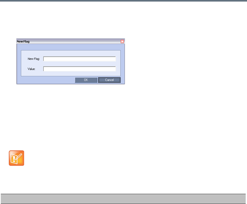
System Configuration Flags
Polycom®, Inc. 777
To add a flag:
1In the System Flags dialog, click New Flag.
The New Flag dialog box is displayed.
2In the New Flag field enter the flag name.
3In the Value field enter the flag value.
The flags in the Manually Added, Modified, Deleted System Flags table can be manually added
to the MCMS_PARAMETERS_USERS tab.
4Click OK to close the New Flag dialog.
The new flag is added to the flags list.
5Click OK to close the System Flags dialog.
:
Unless indicated otherwise, reset the MCU is required for flag changes (including deletion) to take
effect. For more information see Resetting the Collaboration Server.
Manually Added, Modified, Deleted System Flags
Flag Description
ACCEPT_VOIP_DTMF_TYPE Defines the type of DTMF tones (inband) or digits (outband) that the
Collaboration Server will accept in VOIP calls.
Range:
•0 - Auto (default):
Inband or outband DTMF tones/digits are accepted depending on the
endpoint's current setting. If the endpoint switches from inband to
outband, and vice versa, the value of the
SET_DTMF_SOURCE_DIFF_IN_SEC flag determines the time interval
after which both inband and outband tones/digits will be accepted.
•1 - Outband (H.245) only
•2 - Inband only
System Configuration Flags
Polycom®, Inc. 778
ALLOW_SIREN7_CODEC When a Lync server is configured to allow 33Kbps audio rate, Lync
clients connecting the MCU, and using audio rates smaller than
42Kbps, fail, thus disconnecting the call.
To prevent that, Siren7 audio codec is supported by the MCU, and
is the preferred codec for SIP/Lync calls.
Range:
• YES - Siren7 is the preferred audio codec for SIP/Lync calls.
•NO - Siren7 audio codec is not supported.
Default value: NO
Note: No system is required for the flag changed value to take effect.
ALWAYS_FORWARD_DTMF_IN_G
W_SESSION_TO_ISDN
When set to YES, all DTMF codes sent by participants in the GW session
will be forwarded to all PSTN and ISDN participants in the same GW
session.
Range: YES / NO
Default Value: NO
ANAT_IP_PROTOCOL If YES, enables Alternative Network Address Types. For more information,
see Alternative Network Address Types (ANAT).
Range: DISABLED, AUTO, PREFER_IPv4, PREFER_IPv6
Default:
•ULTRA SECURE MODE: NO
•STANDARD SECURITY MODE: YES
APACHE_KEEP_ALIVE_TIMEOUT If the connection is idle for longer than the number of seconds specified by
this flag, the connection to the Collaboration Server is terminated.
Value: 0 - 999
Default: 15
Default (ULTRA_SECURE_MODE=YES): 15
Note: A value of 0 results in an unlimited keep-alive duration. This value
should never be used in Ultra Secure Mode.
AVOID_VIDEO_LOOP_BACK_IN_C
ASCADE
When set to YES the current speaker’s image is not sent back through the
participant link in cascaded conferences with conference layouts other than
1x1.
Default: YES
Range: YES / NO
Manually Added, Modified, Deleted System Flags
Flag Description

System Configuration Flags
Polycom®, Inc. 779
BLOCK_CONTENT_LEGACY_FOR
_LYNC
This flag is used to control the system behavior in an environment where
some Lync clients use the Polycom CCS plug-in and some do not.
When set to NO (default), Content is sent to all Lync clients over the video
channel, including those with the plug-in installed, even when the Send
Content to Legacy Endpoints is disabled. Other, non-Lync legacy endpoints
will not be affected by this flag and will receive content according to the
Send Content to Legacy Endpoints settings in the conference Profile.
When set to YES, Content is not sent to Lync clients over the video channel
including those with the Polycom CCS plug-in installed, even when the
Send Content to Legacy Endpoints is enabled. Other, non-Lync legacy
endpoints will not be affected by this flag and will receive content according
to the Send Content to Legacy Endpoints settings in the conference Profile.
BONDING_DIALING_METHOD When set to:
•SEQUENTIAL
The MCU initiates channel connections sequentially until it reaches the
number of channels defined by the
BONDING_NUM_CHANNELS_IN_GROUP flag.
When a channel is connected, dialing begins for the next channel in the
group.
•BY_TIMERS
The MCU initiates channel connections sequentially using the values of
the BONDING_CHANNEL _DELAY and BONDING_GROUP_DELAY
flags.
The first group of channels is dialed, using the
BONDING_CHANNEL_DELAY between dialing attempts for each
channel in the group.
The Collaboration Server then implements the
BONDING_GROUP_DELAY, before dialing the first channel of the next
group.
Default: SEQUENTIAL
BONDING_GROUP_DELAY
(ISDN)
When connecting several bonding groups, this is the delay (number of
1/100 seconds) preceding the first dialing attempt to connect the next
bonding group.
Default: 500
BONDING_NUM_CHANNELS_IN_
GROUP
(ISDN)
The number of channels in the bonding group to be connected before
dialing the next sequential channel.
Default: 50
BURN_BIOS Although not recommended, setting this flag’s value to NO will prevent
BIOS upgrade.
Default: YES.
CAC_ENABLE When set to YES, enables the Call Admission Control implementation in the
Collaboration Server.
Default: NO (CAC is disabled)
Manually Added, Modified, Deleted System Flags
Flag Description

System Configuration Flags
Polycom®, Inc. 780
CASCADE_LINK_PLAY_TONE_ON
_CONNECTION
When set to YES, the RealPresence Collaboration Server plays a tone
when a cascading link between conferences is established. The tone is
played in both conferences.
This tone is not played when the cascading link disconnects from the
conferences.
The tone used to notify that the cascading link connection has been
established cannot be customized.
Default value: NO.
The tone volume is controlled by the same flag as the IVR messages and
tones: IVR_MESSAGE_VOLUME.
CELL_IND_LOCATION Change the location of the display of Network Quality Indicators displayed
in the cells of the conference Video Layout.
Default: TOP_RIGHT
Range:
•BOTTOM_LEFT
•BOTTOM_RIGHT
•TOP_LEFT
•TOP_RIGHT
CFG_KEY_ENABLE_FLOW_CONT
ROL_REINVITE
Used to enable or disable sending a re-INVITE to endpoints to adjust their
data rate. When set to YES, re-INVITE is used for endpoints that do not
support flow control in SIP using either the Information or RTCP Feedback
mechanisms.
Default: NO.
CONF_GATHERING_DURATION_S
ECONDS
The value of this System Flag sets the duration of the Gathering Phase in
seconds. The Gathering Phase duration of the conference is measured
from the scheduled start time of the conference.
Range: 0 - 3600
Default: 180
For more information see Video Preview (AVC Participants Only)
CP_REGARD_TO_INCOMING_SE
TUP_RATE
For use in the Avaya Environment.
If set to YES, the RealPresence Collaboration Server calculates the line
rate for incoming calls in CP conferences, according to the line rate which is
declared by the endpoint in the H.225 setup message.
If set to NO, the rate is calculated according to the conference line rate
regardless of the rate in the H.225 setup message.
Default: YES.
CPU_BONDING_LINK_MONITORI
NG_FREQUENCY
Used when using the MII Monitor for troubleshooting networks.This flag
sets the MII Polling Interval in milliseconds. A value of zero disables MII
monitoring.
Default: 100
Manually Added, Modified, Deleted System Flags
Flag Description

System Configuration Flags
Polycom®, Inc. 781
CPU_BONDING_MODE Sets the Bonding Mode of the Signalling and Management network
interface controllers.
Mode=6, balance-alb,
(Adaptive Load Balancing) includes balance-tlb, (Transmit Load Balancing)
and balance-rlb (Receive Load Balancing) for IPV4 traffic. No special
switch support is required.
Receive Load Balancing is achieved by ARP negotiation.
Outbound ARP Replies are intercepted and their source hardware address
is overwritten with the unique hardware address of one of the slaves in the
bond. In this way different peers will use different hardware addresses for
the server.
Note: balance-alb is the only supported value. All other possible values are
for troubleshooting purposes only.
Default: balance-alb
Possible values:
•balance-alb
•balance-rr
•active-backup
•balance-xor
•broadcast
•802.3ad
•balance-tlb
DETECT_H323_EP_DISCONNECT
_TIMER
On detecting a H.323 endpoint disconnection, a new system flag,
DETECT_H323_EP_DISCONNECT_TIMER allows you to specify the
amount of time the MCU waits before disconnecting the endpoint.
DETECT_SIP_EP_DISCONNECT
_TIMER
On detecting a SIP endpoint disconnection, a new system flag,
DETECT_SIP_EP_DISCONNECT_TIMER allows you to specify the
amount of time the MCU waits before disconnecting the endpoint
DELAY_BETWEEN_H320_DIAL_O
UT_PARTY
The delay in milliseconds that the MCU waits when connecting dial out
ISDN and PSTN participants.
Default: 1000
DISABLE_CELLS_NETWORK_IND Disable the display of Network Quality Indicators displayed in the cells of
the conference Video Layout.
Default: YES
Range: YES / NO
DISABLE_DUMMY_REGISTRATIO
N
Enables or disables SIP dummy registration on the domain.
Possible Values:
NO (Default) - Disables SIP dummy registration.
YES - Enables SIP dummy registration.
Note: For homologation and certification testing, the flag must be set to
YES.
Manually Added, Modified, Deleted System Flags
Flag Description
System Configuration Flags
Polycom®, Inc. 782
DISABLE_GW_OVERLAY_INDICAT
ION
When set to NO (default), displays progress indication during the
connection phase of a gateway call.
Set the value to YES to hide the connection indications displayed on the
participant’s screen during the connection phase of a gateway call.
DISABLE_SELF_NETWORK_IND Disable the display of the Network Quality Indicator of the participant’s own
endpoint.
Default: NO
Range: YES / NO
NOTE: This flag’s function has been replaced by the Network Quality check
box in the Layout Indications tab of the New Profile / Profile Properties
dialog.
DISABLE_WIDE_RES_TO_SIP_DI
AL_OUT
When set to NO (default), the RealPresence Collaboration Server sends
wide screen resolution to dial-out SIP endpoints. Endpoint types that do not
support wide screen resolutions are automatically identified by the
Collaboration Server according to their product type and version and will
not receive the wide resolution even if the flag is set to YES.
When manually added and set to YES, the RealPresence Collaboration
Server does not send wide screen.
Default: NO.
DTMF_FORWARD_ANY_DIGIT_TI
MER_SECONDS
Used for DTMF code suppression in cascading conferences.
Determines the time period (in seconds) that MCU A will forward DTMF
inputs from conference A participants to MCU B.
Flag range (in seconds): 0 - 360000
This flag is defined on MCU A (the calling MCU).
For more information, see Setting the Video Layout in Cascading
conferences.
ENABLE_CISCO_GK When set to YES, it enables the use of an identical prefix for different
Collaboration Servers when registering with a Cisco MCM Gatekeeper.
Default: NO.
ENABLE_CLOSED_CAPTION Enables or disables the Closed Captions option that allow endpoints to
endpoints to provide real-time text transcriptions or language translations of
the video conference.
When set to NO (default), Closed Captions are disabled.
When set to YES, Closed Captions are enabled.
Manually Added, Modified, Deleted System Flags
Flag Description

System Configuration Flags
Polycom®, Inc. 783
ENABLE_CONTENT_OF_768_FOR
_1024_LV
Generally, the content rate used for 1024 Kbps conferences with a Live
Video settings is 512 Kbps. Set this flag to YES, to increase the content
rate in this scenario to 768 Kbps.
This flag is applicable for protocols supporting H.264 media protocol usage:
•H.263 and H.264 auto selection
•H.264 HD
•H.264 Cascade Optimized
Range: YES, NO
Default: NO
Modifying flag values requires manual addition with no system reset.
ENABLE_EPC When set to YES (default), enables Polycom proprietary People+Content.
When set to NO, disables this feature for all conferences and participants.
ENABLE_FLOW_CONTROL_REIN
VITE
Used to enable or disable sending a re-INVITE to endpoints to adjust their
data rate. When set to YES, re-INVITE is used for endpoints that do not
support flow control in SIP using either the Information or RTCP Feedback
mechanisms.
Default: NO
ENABLE_EXTERNAL_DB_ACCES
S
If YES, the Collaboration Server connects to an external database
application, to validate the participant’s right to start a new conference or
access a conference.
Default: NO
ENABLE_H239 When set to YES, Content is sent via a separate Content channel.
Endpoints that do not support H.239 Content sharing will not be able to
receive
When set to NO, the Content channel is closed. In such a case, H.239
Content is sent via the video channel (“people” video) enabling endpoints
that do not support H.239 Content sharing to receive the Content in their
video channel.
Default: YES
ENABLE_H239_ANNEX_T In H.239-enabled MIH Cascading, when MGC is on level 1, enables
sending Content using Annex T.
ENABLE_LYNC_RTCP_INTRA When set to YES, RTCP FIR is used for sending Intra Requests. When set
to NO Intra Requests are sent using SIP INFO Messages.
Range: YES / NO
Default: NO
ENABLE_MCCF Enables or disables the support of External IVR Services via the
MCCF-IVR package is enabled. In Ultra Secure Mode and in secured
environments where the External IVR Services via the MCCF-IVR package
is not required and unused ports should be closed, this flag should be set to
NO.
Range: YES / NO
Default: YES (in Standard security Mode) or NO (in Ultra Secure Mode)
Manually Added, Modified, Deleted System Flags
Flag Description

System Configuration Flags
Polycom®, Inc. 784
ENABLE_MS_FEC Enables the Microsoft FEC (Forward Error Correction) support for RTV.
Range: Auto/No
Default: Auto
When set to Auto, FEC support is enabled. FEC uses the DV00 option
(DV=00 - one FEC per frame using XOR). When set to No, FEC support is
disabled.
ENABLE_NO_VIDEO_RESOURCE
S_AUDIO_ONLY_MESSAGE
Enables playing a voice message that Informs the participant of the lack of
Video Resources in the RealPresence Collaboration Server and that he/she
is being connected as Audio Only.
Default: YES
ENABLE_RECORDING_
OPERATION_VIA_SIPINFO
Allows recording control operations to be performed using either DTMF
tones or a SIP INFO request.
When set to NO: The Collaboration Server will send Recording Control
Operation commands to the Capture Server using DTMF as in all previous
version.
When set to YES: The Collaboration Server will send Recording Control
Operation commands to the Capture Server using a SIP INFO request.
Default: NO
ENABLE_RTP_TRAFFIC_SHAPIN
G
Indicates whether traffic shaping, which is responsible for flattening packet
bursts within 100 msec time intervals, is enabled. When set to YES, traffic
shaping is applied to all ports, resulting in some port capacity reduction in
MCUs with MPMx/MPMRx cards (see Capacity Reduction During Traffic
Shaping). When set to NO, traffic shaping is disabled.
Range: YES, NO
Default: NO
ENABLE_SELECTIVE_MIXING Enables (default) or disables the Automatic muting of noisy AVC endpoints.
For more details, see Automatic Muting of Noisy Endpoints.
When set to YES, the automatic muting of noisy endpoints can be enabled
or disabled at the conference level in the Conference Profile - Audio
Settings dialog box.
When set to NO, the automatic muting of noisy endpoints is disabled at the
conference level and cannot be enabled in the Conference Profile - Audio
Settings dialog box.
Default: YES
Note: MCU reset is not required when changing the flag value, though
change will apply only for conferences created from that point onward.
ENABLE_SIP_PEOPLE_PLUS_CO
NTENT
If security is of higher priority than SIP Content sharing, SIP
People+Content can be disabled by setting this System Flag to NO. (The
content management control (BFCP) utilizes an unsecured channel
(60002/TCP) even when SIP TLS is enabled.)
Default: YES
Manually Added, Modified, Deleted System Flags
Flag Description

System Configuration Flags
Polycom®, Inc. 785
ENABLE_SIP_PPC_FOR_ALL_US
ER_AGENT
When set to YES, SIP People+Content and BFCP capabilities are declared
with all vendors’ endpoints.
Default: YES
Range: YES / NO
ENABLE_SIRENLPR Enable / disable SirenLPR Audio Algorithm for use in IP (H.323, SIP) calls
in both CP and VSW conferences.
Range: YES / NO
Default: YES
ENABLE_SIRENLPR_SIP_ENCRY
PTION
Enables the SirenLPR audio algorithm when using encryption with the SIP
protocol.
Range: YES / NO
Default: NO
ENABLE_TC_PACKAGE Enables or disables Network Traffic Control.
Range: YES / NO
Default: NO
ENABLE_TEXTUAL_CONFERENC
E_STATUS
Set the value of this flag to NO to disable Text Indication. This setting is
recommended for MCUs running Telepresence conferences.
Default: YES.
ENABLE_VIDEO_PREVIEW Enables the Video Preview feature.
Default: YES.
For more details, see Video Preview (AVC Participants Only).
EXTERNAL_CONTENT_DIRECTO
RY
The Web Server folder name. Change this name if you have changed the
default names used by the DMA application.
Default: /PlcmWebServices
EXTERNAL_CONTENT_IP Enter the IP address of the DMA server in the format:
http://[IP address of the DMA server].
For example, http://172.22.185.89.
This flag is also the trigger for replacing the internal Collaboration Server
address book with the DMA global Address Book.
When empty, the integration of the DMA address book with the
Collaboration Server is disabled.
EXTERNAL_CONTENT_PASSWO
RD
The password associated with the user name defined for the Collaboration
Server in the DMA server.
EXTERNAL_CONTENT_PORT The DMA port used by the Collaboration Server to send and receive XML
requests/responses.
Default: 80.
EXTERNAL_CONTENT_USER The login name defined for the Collaboration Server in the DMA server
defined in the format:
domain name/user name.
Manually Added, Modified, Deleted System Flags
Flag Description
System Configuration Flags
Polycom®, Inc. 786
EXTERNAL_DB_DIRECTORY Applicable to the RealPresence Collaboration Server (RMX)
1500/2000/4000 only.
The URL of the external database application. For the sample script
application, the URL is:
<virtual directory>/SubmitQuery.asp
EXTERNAL_DB_IP Applicable to the RealPresence Collaboration Server (RMX)
1500/2000/4000 only.
The IP address of the external database server, if one is used.
Default: 0.0.0.0
EXTERNAL_DB_LOGIN Applicable to the RealPresence Collaboration Server (RMX)
1500/2000/4000 only.
The login name defined for the Collaboration Server in the external
database server.
Default: POLYCOM
EXTERNAL_DB_PASSWORD Applicable to the RealPresence Collaboration Server (RMX)
1500/2000/4000 only.
The password associated with the user name defined for the Collaboration
Server on the external database server.
Default: POLYCOM
EXTERNAL_DB_PORT Applicable to the RealPresence Collaboration Server (RMX)
1500/2000/4000 only.
The external database server port used by the Collaboration Server to send
and receive XML requests/responses.
For secure communications set the value to 443.
Default: 5005.
FORCE_1X1_LAYOUT_ON_CASC
ADED_LINK_CONNECTION
When set to YES, the cascaded link is automatically set to Full Screen
(1x1) in CP conferences forcing the speaker in one cascaded conference to
display in full window in the video layout of the other conference.
Set this flag to NO when connecting to an MGC using a cascaded link, if the
MGC is functioning as a Gateway and participant layouts on the other
network are not to be forced to 1X1.
Default: YES
Manually Added, Modified, Deleted System Flags
Flag Description

System Configuration Flags
Polycom®, Inc. 787
FORCE_AUDIO_CODEC_FOR_MS
_SINGLE_CORE
This flag is used to force the use of a specific Audio algorithm when a
Microsoft Office Communicator R2 or Lync Client is hosted on a workstation
with a single core processor. The flag value overrides the default audio
algorithm selection (G.722.1) that may cause audio quality problems when
G.722.1 is used by Microsoft Clients running on single processor
workstations.
This flag can be set to:
• AUTO – No forcing occurs and the Collaboration Server negotiates a full
set of Audio algorithm during capabilities exchange.
• G711A/U or G722 – Set this flag value according to the hosting
workstation capabilities. If the Collaboration Server detects single core
host during capabilities exchange it will assign a G.711 or G.722 Audio
algorithm according to the flag value.
Possible values: AUTO, G711A, G711U, G722
Default: G711A
FORCE_ENCRYPTION_FOR_UND
EFINED_PARTICIPANT_IN_WHEN
_AVAILABLE_MODE
When set to YES, Undefined participants must connect encrypted,
otherwise they are disconnected.
When set to NO (default) and the conference Encryption in the Profile is set
to Encrypt When Possible, both Encrypted and Non-encrypted Undefined
participants can connect to the same conferences, where encryption is the
preferred setting.
Default: NO
FORCE_G711A Setting this flag forces the use of the G711A Audio Codec.
Possible values: YES / NO
Default: NO
FORCE_RESOLUTION Use this flag to specify IP (H.323 and SIP) endpoint types that cannot
receive wide screen resolution and that were not automatically identified as
such by the Collaboration Server.
Possible values are endpoint types, each type followed by a semicolon. For
example, when disabling Wide screen resolution in an HDX endpoint enter
the following string: HDX;
Note: Use this flag when the flag SEND_WIDE_RES_TO_IP is set to YES.
FORCE_STATIC_MB_ENCODING This flag supports Tandberg MXP mode of sending and receiving video by
IP endpoint in HD 720p resolution and Video Quality set to Motion. This
mode is not supported for ISDN endpoints.
Default value: Tandberg MXP.
To disable this flag, enter NONE.
G728_IP Enables or disables declaration of G.728 Audio Algorithm capabilities in IP
calls.
Range: YES / NO
Default: NO
Manually Added, Modified, Deleted System Flags
Flag Description

System Configuration Flags
Polycom®, Inc. 788
G728_ISDN Enables or disables declaration of G.728 Audio Algorithm capabilities in
ISDN calls.
Range: YES / NO
Default: NO
H239_FORCE_CAPABILITIES When the flag is set to NO, the Collaboration Server only verifies that the
endpoint supports the Content protocols: Up to H.264 or H.263.
When set to YES, the Collaboration Server checks frame rate, resolution
and all other parameters of the Content mode as declared by an endpoint
before receiving or transmitting Content.
Default: NO.
H264_HD_GRAPHICS_MIN_CONT
ENT_RATE
Determines the minimum content rate (in kbps) required for endpoints to
share H.264 high quality content via the Content channel When Content
Setting is Graphics.
Range: 0-1536
Default: 128
H264_HD_HIGHRES_MIN_CONTE
NT_RATE
Determines the minimum content rate (in kbps) required for endpoints to
share H.264 high quality content via the Content channel When Content
Setting is Hi Resolution Graphics.
Range: 0-1536
Default: 256
H264_HD_LIVEVIDEO_MIN_CONT
ENT_RATE
Determines the minimum content rate (in kbps) required for endpoints to
share H.264 high quality content via the Content channel When Content
Setting is Live Video.
Range: 0-1536
Default: 384
H323_FREE_VIDEO_RESOURCES For use in the Avaya Environment.
In the Avaya Environment there are features that involve converting
undefined dial-in participants’ connections from video to audio (or vice
versa). To ensure that the participants’ video resources remain available for
them, and are not released for use by Audio Only calls, set this flag to NO.
If set to YES, the Collaboration Server will release video resources for
Audio Only calls.
Default: YES.
HIDE_CONFERENCE_PASSWOR
D
If set to YES (default in Ultra Secure Mode):
•Conference and Chairperson Passwords that are displayed in the
Collaboration Server Web Client or RMX Manager are hidden when
viewing the properties of the conference.
•Automatic generation of passwords (both conference and chairperson
passwords) is disabled, regardless of the settings of the flags:
NUMERIC_CONF_PASS_DEFAULT _LEN
NUMERIC_CHAIR_PASS_ DEFAULT_LEN.
For more information see Automatic Password Generation Flags.
Default: NO.
Manually Added, Modified, Deleted System Flags
Flag Description
System Configuration Flags
Polycom®, Inc. 789
IGNORE_AIM Audio Indicate Muted (AIM) is Relevant to H.323 endpoints. When an
endpoint mutes its microphone, it does not necessarily mute its entire audio
stream. This allows sharing of Content that includes audio while
microphones are muted.
When set to:
NO - When the AIM signal is received, the participant is muted and a mute
icon is displayed in the RMX Web Client / RMX Manager.
YES - When the AIM signal is received, the participant is not muted and a
mute icon is not displayed in the RMX Web Client / RMX Manager.
Range: YES, NO
Default: NO
IP_LINK_ENVIRONMENT In H.239-enabled MIH Cascading, when MGC is on level 1, setting this flag
to YES will adjust the line rate of HD Video Switching conferences run on
the RealPresence Collaboration Server (RMX) 1500/1800/2000/4000 from
1920Kbps to 18432, 100bits/sec to match the actual rate of the IP Only HD
Video Switching conference running on the MGC.
Note: If the flag MIX_LINK_ENVIRONMENT is set to NO, the
IP_ENVIRONMENT_LINK flag must be set to YES.
IP_RESPONSE_ECHO When the System Flag value is YES, the Collaboration Server will respond
to ping (IPv4) and ping6 (IPv6) commands. When set to NO, the
Collaboration Server will not respond to ping and ping6 commands.
IPV6_AUTO_ADDRESS_CONFIGU
RATION_METHOD
SLAAC (Stateless Address Auto Configuration) and DHCPv6 related
system behavior is controlled by setting this flag’s value as required.
Range: AUTO / SLAAC
AUTO—(default) Use DHCPv6 first in case of failure use SLAAC.
SLAAC—Use SLAAC only.
ITP_CERTIFICATION When set to NO (default), this flag disables the telepresence features in the
Conference Profile.
Set the flag to YES to enable the telepresence features in the Conference
Profile (provided that the appropriate License is installed).
LAN_REDUNDANCY Enables Local Area Network port redundancy on RealPresence
Collaboration Server (RMX) 2000/4000 RTM LAN Card and RealPresence
Collaboration Server (RMX) 1500 LAN ports on the RTM IP 1500.
Range: YES / NO
Default: NO
Note: If the flag value is set to YES and either of the LAN connections
(LAN1 or LAN2) experiences a problem, an active alarm is raised stating
that there is no LAN connection, specifying both the card and port number.
Manually Added, Modified, Deleted System Flags
Flag Description

System Configuration Flags
Polycom®, Inc. 790
LPR_CONTENT_RATE_ADJUST_
WEAK_LPR
When LPR is initiated by an endpoint in an AVC-CP conference due to
experienced packet loss, the MCU reduces video rate (minimum is 64K) to
avoid exceeding bandwidth.
At times, further reduction is required to preserve the bandwidth, which is
regulated by this system flag.
Set this flag valustep e to YES, to enable H.323 endpoints to reduce their
content rate or LPR strength as follows:
• For single MCU conferences:
VSW content - Drop content rate upon packet loss condition.
Transcoding - Drop content rate upon packet loss condition for the
protocol used by the endpoint experiencing the packet loss.
• For cascaded conferences:
VSW content - Decrease LPR strength (from 5% to 2%).
Transcoding:
If packet loss occurs at one of the local endpoints, drop content rate
upon packet loss condition for the protocol used by the endpoint
experiencing the packet loss.
If packet loss occurs at the cascaded link, Decrease LPR strength
(from 5% to 2%).
If you set this flag to NO, the content rate is not reduced, and MCU packet
loss protection is guaranteed for 5%.
Range: YES / NO
Default: NO
Notes:
•No system restart is required for this flag new value to take effect.
•This flag should not be set to YES in systems using TIP conferencing.
LYNC_AVMCU_1080p30_ENCODE
_RESOLUTION
MS AV MCU Cascade deployment supports HD1080p30 video resolution
according to the settings of this flag only if Video Optimized mode is
selected.
Range: YES / NO
Default: NO
•NO—Video streams sent to and received from the MS AV MCU are
HD720p30, SD, and CIF.
• YES—Video streams sent to the MS AV MCU are HD1080p30, SD, CIF.
Video streams received from the MS AV MCU are 720p30,SD, and CIF.
For more information see Video Resource Requirement Selection in Lync
2013 AVMCU Cascade.
Manually Added, Modified, Deleted System Flags
Flag Description
System Configuration Flags
Polycom®, Inc. 791
MANAGE_TELEPRESENCE_ROO
M_SWITCH_LAYOUTS
Determines whether the MLA or the RMX controls the Room Switch
Telepresence Layouts.
•When set to NO, the RMX does not manage Telepresence Room Switch
Layouts and they continue to be managed by the MLA.
•When set to YES, the RMX manages Telepresence Room Switch
Layouts.
Default: NO
Range: YES / NO
Note: System re-start is not required for this flag’s settings to take effect.
For more information see Room Switch Telepresence Layouts.
MAX_ALLOWED_RTV_HD_FRAM
E_RATE
Defines the threshold Frame Rate (fps) in which RTV Video Protocol
initiates HD resolutions.
Flag values are as follows:
Range: 0-30 (fps)
Default: 0 (fps) - Implements any Frame Rate based on Lync RTV Client
capabilities
MAX_RTV_RESOLUTION Enables you to override the Collaboration Server resolution selection and
limit it to a lower resolution, hence minimizing the resource usage to 1 or
1.5 video resources per call instead of 3 resources. Possible flag values
are:
AUTO (default), QCIF, CIF, VGA or HD720.
MAX_MS_SVC_RESOLUTION Used to minimizing the resource usage by overriding the default resolution
selection and limiting it to a lower resolution.
Range: AUTO, CIF, VGA, HD720, HD1080
Default: AUTO
The MAX_MS_SVC_RESOLUTION System Flag operates independently
from the MAX_RTV_RESOLUTION System Flag allowing differing
maximum resolutions to be selected for the MS SVC and RTV protocols.
MAX_TRACE_LEVEL This flag indicates the debugging level for system support.
Possible values:
TRACE = t
DEBUG = d
INFO_NORMAL = n
INFO_HIGH = i
WARN = w
ERROR = e
FATAL = f
OFF = o
Default: n
Manually Added, Modified, Deleted System Flags
Flag Description

System Configuration Flags
Polycom®, Inc. 792
MAXIMUM_RECORDING_LINKS The maximum number of Recording Links available for selection in the
Recording Links list and the Conference Profile - Recording dialog box.
Range: 1 - 100
Default: 20
MEDIA_NIC_MTU_SIZE The maximum data payload size (bytes) transmitted in a single packet over
the network, and should be minimally the MTU_SIZE (see below) to avoid
fragmenting of data packets.
The Collaboration Server sends large amount of data over the network and
may be required to adjust its MTU size according to the network
environment in which it is deployed.
MTU configuration is applicable to Collaboration Servers with RTM-LAN
cards installed only.
Range: 500-20,000. Values outside that range are treated as 1,500.
Default: 1,500
MIN_H239_HD1080_RATE Used to set the threshold line rate for HD Resolution Content: the line rate
at which the Collaboration Server will send Content at HD1080 Resolution.
Setting the flag to 0 disables HD Resolution Content.
Default: 768 kbps.
MINIMUM_FRAME_RATE_THRES
HOLD_FOR_SD
Low quality, low frame rate video is prevented from being sent to endpoints
by ensuring that an SD channel is not opened at frame rates below the
specified value.
Range: 0 -30
Default: 15
MIX_LINK_ENVIRONMENT In H.239-enabled MIH Cascading, when MGC is on level 1, setting this flag
to YES will adjust the line rate of HD Video Switching conferences run on
the RealPresence Collaboration Server (RMX) 1500/1800/2000/4000 from
1920Kbps to 17897, 100bits/sec to match the actual rate of the HD Video
Switching conference running on the MGC.
Note: If the flag MIX_LINK_ENVIRONMENT is set to YES, the
IP_ENVIRONMENT_LINK flag must be set to NO.
MS_CAC_AUDIO_MIN_BR The minimum bit rate for audio using the Microsoft CAC (Call Admission
Control) protocol. When the bit rate is lower than the
MS_CAC_AUDIO_MIN_BR, the call is not connected.
Range: 0 - 384
Default: 30
MS_CAC_VTDEO_MIN_BR The minimum bit rate for video using the Microsoft CAC (Call Admission
Control) protocol. When the bit rate is lower than the
MS_CAC_VIDEO_MIN_BR, the call is not connected as a video call..
Range: 0 - 384
Default: 40
Manually Added, Modified, Deleted System Flags
Flag Description

System Configuration Flags
Polycom®, Inc. 793
MS_PROXY_REPLACE Enables the proxy=replace parameter in the SIP Header. When set to YES
the outbound proxy to replaces the contact information in the contact
header with its own enabling other clients and servers to reach the client
using the proxy's IP address, even if the client is behind a firewall.
Possible Values: YES / NO
Default: YES
NETWORK_IND_CRITICAL_PERC
ENTAGE
The percentage degradation due to packet loss required to change the
indicator from Major to Critical.
Default: 5
NETWORK_IND_MAJOR_PERCEN
TAGE
The percentage degradation due to packet loss required to change the
indicator from Normal to Major.
Default: 1
NUM_OF_INITIATE_HELLO_MESS
AGE_IN_CALL_ESTABLISHMENT
Indicates how many times the Hello (keep alive) message is sent from the
Collaboration Server to the endpoint in an environment that includes a
Session Border Controller (SBC) with a 3-second interval between
messages.
Range: 1 to 10.
Default:3
NUM_OF_PCM_IN_MPMX In Collaboration Server 1500/2000/4000 systems with MPMx cards, sets
the maximum number of PCM sessions.
The default value of this flag is set according to the SVC license:
1 - If SVC is enabled in the license (the only possible value).
4 - If SVC is disabled in the license
Range: 1-4 (If SVC is disabled in the license).
NUMBER_OF_REDIAL Enter the number re dialing attempts required. Dialing may continue until
the conference is terminated.
Default: 3
OCSP_RESPONDER_TIMEOUT Not Supported in RMX 1800.
Determines the number of seconds the RMX is to wait for an OCSP
response from the OCSP Responder before failing the connection.
Network latency or slow WAN links can cause login problems when logging
in to the RMX’s Management Network.This System Flag’s value determines
the number of seconds the MCU is to wait for an OCSP response from the
OCSP Responder before failing the connection.
Default: 3 (seconds)
Range: 1-20 (seconds)
PARTY_GATHERING_DURATION_
SECONDS
The value of this System Flag sets the duration, in seconds, of the display
of the Gathering slide for participants that connect to the conference after
the conference start time.
Range: 0 - 3600
Default: 15
For more information see Video Preview (AVC Participants Only).
Manually Added, Modified, Deleted System Flags
Flag Description
System Configuration Flags
Polycom®, Inc. 794
PASSWORD_FAILURE_LIMIT The number of unsuccessful Logins permitted in Ultra Secure Mode.
Default: 3
PCM_FECC Determines whether the DTMF Code, ##, the Far/Arrow Keys (FECC) or
both will activate the PCM interface. This flag can be also be used in
combination with DTMF code definitions to disable PCM.
Possible Values: YES / NO
Default: YES.
PCM_LANGUAGE Determines the language of the PCM interface.
Possible Values are: ENGLISH, CHINESE_SIMPLIFIED,
CHINESE_TRADITIONAL, JAPANESE, GERMAN, FRENCH, SPANISH,
KOREAN, PORTUGUESE, ITALIAN, RUSSIAN, NORWEGIAN
Default: Current Collaboration Server Web Client language.
PORT_GAUGE_ALARM When set to YES, if system resource usage reaches the High Port Usage
Threshold as defined for the Port Gauges, System Alerts in the form of an
Active Alarm and an SNMP trap are generated.
PRESERVE_ICE_CHANNEL_IN_C
ASE_OF_LOCAL_MODE
When set to NO (default), local the ICE channel is closed after applying
CAC bandwidth management when Call Admission Control is enabled in
the local network.
When set to YES, the ICE channel is preserved open throughout the call.
Default: NO
PRESERVE_PARTY_CELL_ON_F
ORCE_LAYOUT
Used to prevent reassignment of cells in a forced layout that were assigned
to endpoints that have disconnected, paused their video, or have been
removed from the conference. The cell will remain black until the endpoint
reconnects or a new layout is used, or the conference ends.
Range: YES / NO
Default: NO
•NO - Cells of dropped endpoints are reassigned. Endpoints that
reconnect will be treated as new endpoints.
•YES - Cells of dropped endpoints are not reassigned, but will be
reserved until the endpoint reconnects.
Forced Layout Guidelines:
•It is recommended that this flag be set to YES if the Collaboration Server
is used primarily for ITP conferences with MLA.
•When a new forced layout is sent to the MCU, the MCU no longer
preserves the cells for disconnected participants. The layout is redrawn
using the currently connected participants only.
•If the dropped endpoint was forced to use a particular cell, and that cell
is switched from forced layout to automatically assigned, the MCU no
longer preserves the cell. Any other endpoint can be assigned that
particular cell.
•This feature works the same way in Telepresence conferences, even
where the layouts are controlled by MLA.
Manually Added, Modified, Deleted System Flags
Flag Description

System Configuration Flags
Polycom®, Inc. 795
PSTN_RINGING_DURATION_SEC
ONDS
If there is a slow response from the ISDN switch, the PSTN dial-out ringing
duration (in seconds) is used by the Collaboration Server to disconnect the
call.
Default: 45
QOS_IP_AUDIO Used to select the priority of audio packets when DiffServ is the is the
selected method for packet priority encoding.
Default: 0x31
QOS_IP_VIDEO Used to select the priority of video packets when DiffServ is the is the
selected method for packet priority encoding.
Default: 0x31
QOS_MANAGEMENT_NETWORK Enter the DSCP value for the RMX Management Network.
Default: 0x10
Range: 0x00 - 0x3F
REDUCE_CAPS_FOR_REDCOM_
SIP
To accommodate deployments where some devices have limits on the size
of the SDP payload in SIP messages (such as LSCs from Redcom running
older software versions), when the flag value = YES, the SDP size is less
than 2kb and includes only one audio and one video media line.
Default: NO
REDIAL_INTERVAL_IN_SECONDS Enter the number of seconds that the Collaboration Server should wait
before successive re dialing attempts.
Range: 0-30 (Default: 10)
REDUCE_CAPS_FOR_REDCOM_
SIP
To accommodate Redcom’s SDP size limit, when the flag value = YES, the
SDP size is less than 2kb and includes only one audio and one video media
line.
Default: NO
REJECT_INCORRECT_PRECEDE
NCE_DOMAIN_NAME
When set to YES, when the Precedence Domain of a SIP dial-in call does
not match the Precedence Domain of the RMX, the call is rejected. For
more information, see MLPP (Multi Level Precedence and Preemption).
Possible values: YES/NO
Default: No
REMOVE_EP_FROM_LAYOUT_O
N_NO_VIDEO_TIMER
Enables the removal of empty video cells from a Video Layout.
REMOVE_H323_EPC_CAP_TO_N
ON_POLYCOM_VENDOR
Used to disable EPC protocol. Use of Polycom’s proprietary protocol, High
Profile, EPC, may result in interoperability issues when used with other
vendors’ endpoints.
Possible values: YES / NO
Default: NO
Manually Added, Modified, Deleted System Flags
Flag Description

System Configuration Flags
Polycom®, Inc. 796
REMOVE_H323_HIGH_PROFILE_
CAP_TO_NON_POLYCOM_VEND
OR
Used to disable High Profile protocol. Use of Polycom’s proprietary
protocol, High Profile, may result in interoperability issues when used with
other vendors’ endpoints.
Possible values: YES / NO
Default: NO
REMOVE_H323_HIGH_QUALITY_
AUDIO_CAP_TO_NON_POLYCOM
_VENDOR
Used to disable the following Audio Codecs:
•G231
•G7221C
•G7221
•G719
•Siren22
•Siren14
Possible values: YES / NO
Default: NO
REMOVE_H323_LPR_CAP_TO_N
ON_POLYCOM_VENDOR
Used to disable H.323 LPR protocol. Use of Polycom’s proprietary protocol,
H.323 LPR, may result in interoperability issues when used with other
vendors’ endpoints.
Possible values: YES / NO
Default: NO
REMOVE_IP_IF_NUMBER_EXIST
S
Between the time a conference is scheduled and when it becomes active,
the IP of an endpoint may change, especially in an environment that uses
DHCP. This flag determines if the E.164 number is to be substituted for the
IP address in the dial string.
Range: YES / NO
Default: YES - The IP address will be substituted with the E.164 number.
RFC2833_DTMF Controls the receipt of in-band and out-of-band DTMF Codes. When set to:
•YES The RMX will receive DTMF Codes sent in-band.
•NO The RMX receive DTMF Codes sent out-of-band.
The RMX always sends DTMF Codes in-band (as part of the Audio Media
stream).
Range: YES/NO
Default YES
RMX_MANAGEMENT_SECURITY_
PROTOCOL
Enter the protocol to be used for secure communications.
Default: TLSV1_SSLV3 (both).
Default for U.S. Federal licenses: TLSV1.
RTCP_FIR_ENABLE When set to YES, the Full Intra Request (FIR) is sent as INFO (and not
RTCP).
Default = YES
RTCP_FLOW_CONTROL_TMMBR
_ENABLE
Enables/disables the SIP RTCP flow control parameter.
Default: YES
Manually Added, Modified, Deleted System Flags
Flag Description
System Configuration Flags
Polycom®, Inc. 797
RTCP_FLOW_CONTROL_TMMBR
_INTERVAL
Modifies the interval (in seconds) of the TMMBR (Temporary Maximum
Media Stream Bit Rate) parameter for SIP RTCP flow control.
Range: 5 - 999 (seconds)
Default: 180
RTCP_PLI_ENABLE When set to YES, the (Picture Loss Indication (PLI) is sent as INFO (and
not RTCP).
Default = YES
RTCP_QOS_IS_EQUAL_TO_RTP Range: YES/NO
Default: YES
RTV_MAX_BIT_RATE_FOR_FORC
E_CIF_PARTICIPANT
Enables the removal of empty video cells from a Video Layout.
SELF_IND_LOCATION Change the location of the display of the Network Quality Indicator of the
participant’s own endpoint.
Default: BOTTOM_RIGHT
Range:
•TOP_ LEFT
•TOP
•TOP_RIGHT
•BOTTOM_ LEFT
•BOTTOM
•BOTTOM_RIGHT
NOTE: This flag’s function has been replaced by the Network Quality check
box in the Layout Indications tab of the New Profile / Profile Properties
dialog.
SEND_SIP_BUSY_UPON_RESOU
RCE_THRESHOLD
When set to YES, it enables the Collaboration Server to send a busy
notification to a SIP audio endpoint or a SIP device when dialing in to the
Collaboration Server whose audio resource usage exceeded the Port
Usage threshold.
When set to NO, the system does limit the SIP audio endpoint connections
to a certain capacity and will not send a busy notification when the resource
capacity threshold is exceeded.
Default: NO
Manually Added, Modified, Deleted System Flags
Flag Description

System Configuration Flags
Polycom®, Inc. 798
SEND_SRTP_MKI Enables or disables the inclusion of the MKI field in SRTP packets sent by
the Collaboration Server. Setting the value to NO to disables the inclusion
of the MKI field in SRTP packets sent by the Collaboration Server.
Set this flag to:
•NO
When all conferences on the RMX will not have MS-Lync clients
participating and will have 3rd party endpoints participating.
When using endpoints (eg. CounterPath Bria 3.2 Softphone) that
cannot decrypt SRTP-based audio and video streams if the MKI
(Master Key Identifier) field is included in SRTP packets sent by the
Collaboration Server.
This setting is recommended for Maximum Security Environments.
• YES
When any conferences on the RMX will have both MS-Lync clients
and Polycom endpoints participating.
Some 3rd party endpoints may be unsuccessful in participating in
conferences with this setting.
Notes:
•This System Flag must be added and set to YES (default) when
Microsoft Office Communicator and Lync Clients are used as they all
support SRTP with MKI.
•The system flag must be added and set to NO when Siemens phones
(Openstage and ODC WE) are used in the environment as they do not
support SRTP with MKI.
•Polycom endpoints function normally regardless of the setting of this
flag.
Default: YES
SEND_WIDE_RES_TO_IP When set to YES (default), the Collaboration Server sends wide screen
resolution to IP endpoints. Endpoint types that do not support wide screen
resolutions are automatically identified by the Collaboration Server
according to their product type and version and will not receive the wide
resolution even when the flag is set to YES.
When manually added and set to NO, the Collaboration Server does not
send wide screen resolution to all IP endpoints.
Default: YES.
SEND_WIDE_RES_TO_ISDN When set to YES, the Collaboration Server sends wide screen resolution to
ISDN endpoints.
When set to NO (default), the Collaboration Server does not send wide
screen resolution to ISDN endpoints.
Default: NO.
Manually Added, Modified, Deleted System Flags
Flag Description

System Configuration Flags
Polycom®, Inc. 799
SET_AUDIO_CLARITY Audio Clarity improves received audio from participants connected via low
audio bandwidth connections, by stretching the fidelity of the narrowband
telephone connection to improve call clarity. The enhancement is applied to
the following low bandwidth (4kHz) audio algorithms:
•G.729a
•G.7 11
•Guidelines
Note:
This flag sets the initial value for Audio Clarity during First-time Power-up.
Thereafter the feature is controlled via the New Profile - Audio Settings
dialog box.
Possible Values: ON / OFF
Default: OFF
For more information see Defining New Profiles.
SET_AUDIO_PLC Packet Loss Concealment (PLC) for Siren audio algorithms improves
received audio when packet loss occurs in the network.
The following audio algorithms are supported:
•Siren 7 (mono)
•Siren 14 (mono/stereo)
•Siren 22 (mono/stereo)
Possible Values: ON / OFF
Default: ON
Note: The speaker’s endpoint must use a Siren algorithm for audio
compression.
SET_AUTO_BRIGHTNESS Auto Brightness detects and automatically adjusts the brightness of video
windows that are dimmer than other video windows in the conference
layout. Auto Brightness only increases brightness and does not darken
video windows.
Note:
This flag sets the initial value for Auto Brightness during First-time
Power-up. Thereafter the feature is controlled via the New Profile - Video
Quality dialog box.
Possible Values: YES / NO
Default: NO
For more information see Defining New Profiles.
SET_DTMF_SOURCE_DIFF_IN_S
EC
If the ACCEPT_VOIP_DTMF_TYPE flag is set to 0 (Auto) this flag
determines the interval, in seconds after which the Collaboration Server will
accept both DTMF tones (inband) and digits (outband).
Default: 120
Manually Added, Modified, Deleted System Flags
Flag Description

System Configuration Flags
Polycom®, Inc. 800
SIP_BFCP_DIAL_OUT_MODE Controls BFCP’s use of UDP and TCP protocols for dial-out SIP Client
connections according to its value:
• AUTO (Default)
If SIP Client supports UDP, TCP or UDP and TCP:
- BFCP/UDP is selected as Content sharing protocol.
• UDP
If SIP Client supports UDP or UDP and TCP:
- BFCP/UDP selected as Content sharing protocol.
If SIP Client supports TCP
- Cannot share Content.
•TCP
If SIP Client supports TCP or UDP and TCP
- BFCP/TCP selected as Content sharing protocol.
If SIP Client supports UDP
- Cannot share Content.
SIP_DUAL_DIRECTION_TCP_CO
N
In environments set to integration with Microsoft, if set to YES the system
sends a new request on the same TCP connection (instead of opening a
new one).
SIP_ENABLE_FECC By default, FECC support for SIP endpoints is enabled at the MCU level.
You can disable it by manually adding this flag and setting it to NO.
SIP_FAST_UPDATE_INTERVAL_E
NV
Default setting is 0 to prevent the Collaboration Server from automatically
sending an Intra request to all SIP endpoints.
Enter n (where n is any number of seconds other than 0) to let the
Collaboration Server automatically send an Intra request to all SIP
endpoints every n seconds.
It is recommended to set the flag to 0 and modify the frequency in which the
request is sent at the endpoint level (as defined in the next flag).
SIP_FAST_UPDATE_INTERVAL_E
P
Default setting is 6 to let the Collaboration Server automatically send an
Intra request to Microsoft OC endpoints only, every 6 seconds.
Enter any other number of seconds to change the frequency in which the
Collaboration Server send the Intra request to Microsoft OC endpoints only.
Enter 0 to disable this behavior at the endpoint level (not recommended).
SIP_FORMAT_GW_HEADERS_FO
R_REDCOM
Controls whether the RMX adds special gateway prefix and postfix
characters to the user portion of the SIP URI expressed in the From and
Contact headers of SIP messages sent during calls involving Gateway
Services. The addition of these characters can result in call failures with
some SIP call servers. It is recommended to set this flag to YES whenever
the RMX is deployed such that it registers its conferences to a SIP call
server.
Range: YES, NO
Default: NO
Manually Added, Modified, Deleted System Flags
Flag Description

System Configuration Flags
Polycom®, Inc. 801
SIP_FREE_VIDEO_RESOURCES For use in Avaya and Microsoft Environments.
When set to NO (required for Avaya and Microsoft environments), video
resources that were allocated to participants remain allocated to the
participants as long as they are connected to the conference even if the call
was changed to audio only. The system allocates the resources according
to the participant’s endpoint capabilities, with a minimum of 1 CIF video
resource.
Enter YES to enable the system to free the video resources for allocation to
other conference participants. The call becomes an audio only call and
video resources are not guaranteed to participants if they want to add video
again.
Default value in Microsoft environment: NO.
SIP_OMIT_DOMAIN_FROM_PART
Y_NAME
Enables the removal of Domain Names from SIP dial-in participants’ Site
Names. This prevents long domain names being appended to SIP
participant names.
SIP_TCP_PORT_ADDR_STRATEG
Y
Setting the flag to 1 prevents the use of two sockets for one SIP call - one
for inbound traffic, one for outbound traffic. This is done by inserting port
5060/5061 into the Route[0] header.
Possible values:
•0 - Inbound traffic on port 5060/5061 outbound traffic on port 60000
•1 - Both inbound and outbound traffic on port 5060/5061
Default: 0
SOCKET_ACTIVITY_TIMEOUT For use in Microsoft environments.
When the MS_KEEP_ALIVE System Flag is set to YES, the value of this
flag is used as the MS Keep-Alive Timer value.
SUPPORT_HIGH _PROFILE Enables or disables the support of High Profile video protocol in CP
conferences. This flag is specific to CP conferences and has no effect on
VSW conferences.
Range: YES / NO
Default: YES
SUPPORT_HIGH_PROFILE_WITH
_ISDN
Enables or disables the support of High Profile video protocol for ISDN
participants in CP conferences. This flag is specific to CP conferences and
has no effect on VSW conferences.
Range: YES / NO
Default: NO
SUPPORT_MULTIPLE_ICE_USER
S
Enables the configuration of multiple Lync registrations.
TC_BURST_SIZE This flag regulates the Traffic Control buffer or maxburst size as a
percentage of the participant line rate.
Range: 1-30.
Manually Added, Modified, Deleted System Flags
Flag Description

System Configuration Flags
Polycom®, Inc. 802
TC_LATENCY_SIZE This flag limits the latency (in milliseconds) or the number of bytes that can
be present in a queue.
Range: 1-1000 (in milliseconds).
TCP_RETRANSMISSION_TIMEOU
T
The number of seconds the server will wait for a TCP client to answer a call
before closing the connection.
Default = 5 (seconds)
TRAFFIC_SHAPING_MTU_FACTO
R
Used for the MTU (Maximum transmitting Unit - the size of transmitted
packets) dynamic calculation:
New MTU = video bit rate / TRAFFIC_SHAPING_MTU_FACTOR
where the new MTU value is guaranteed to be a minimum of 410, and a
maximum of 1460 (MAX_MTU). The purpose of this calculation is to match
video rate in outgoing video to call rate, yet force lower encoder bit rates to
avoid overflow.
This flag is applicable only when traffic shaping is enabled (see
ENABLE_RTP_TRAFFIC_SHAPING).
Range: 0-5000, where 0 signifies no change in MTU
Default: 800
V35_MULTIPLE_SERVICES Not Supported in RMX 1800.
If the connection of multiple Serial Gateways to RTM-LAN cards is required:
The V35_MULTIPLE_SERVICES System Flag must be set to YES.
The default value of the V35_MULTIPLE_SERVICES System Flag is NO,
enabling only one Serial Gateway to be supported per RTM-LAN card.
V35_ULTRA_SECURED_SUPPOR
T
This flag must be set to YES when deploying a Serial Gateway S4GW in
Ultra Secure Mode.
VIDEO_BIT_RATE_REDUCTION_P
ERCENT
Indicates the percentage of actual reduction in bit rate sent from the RMX to
the endpoint (negotiated bit rate is not reduced). This flag is applicable only
when traffic shaping is enabled (see ENABLE_RTP_TRAFFIC_SHAPING).
Range: 0-60
Default: 15
VSW_CIF_HP_THRESHOLD_BITR
ATE
Controls the Minimum Threshold Line Rate (kbps) for CIF resolution for
High Profile-enabled VSW conferences.
Default: 64
VSW_HD_1080p_HP_THRESHOL
D_BITRATE
Controls the Minimum Threshold Line Rate (kbps) for HD1080p resolution
for High Profile-enabled VSW conferences.
Default: 1024
VSW_HD_720p30_HP_THRESHOL
D_BITRATE
Controls the Minimum Threshold Line Rate (kbps) for HD720p30 resolution
for High Profile-enabled VSW conferences.
Default: 512
Manually Added, Modified, Deleted System Flags
Flag Description

System Configuration Flags
Polycom®, Inc. 803
Manually Adding Flags to the CS_MODULE_PARAMETERS Tab
Using the procedure to manually add flags to the System Configuration, the following flags can be manually
added to the CS_MODULE_PARAMETERS tab:
VSW_HD_720p50_60_HP_THRES
HOLD_BITRATE
Controls the Minimum Threshold Line Rate (kbps) for HD720p50 and
HD720p50 resolutions for High Profile-enabled VSW conferences.
Default: 832
VSW_RATE_TOLERANCE_PEREC
ENT
Determines the percentage of bandwidth that can be deducted from the
required bandwidth to allow participants to connect to the conference.
For example, a value of 20 will allow a participant to connect to the
conference if the allocated line rate is up to 20% lower than the conference
line rate (or between 80% to 100% of the required bandwidth).
Range: 0 - 75
Default: 0
VSW_SD_HP_THRESHOLD_BITR
ATE
Controls the Minimum Threshold Line Rate (kbps) for SD resolution for
High Profile-enabled VSW conferences.
Default: 128
WRONG_NUMBER_DIAL_RETRIE
S
The number of re-dial attempts for a wrong destination number or a wrong
destination number time-out.
Range: 0 - 5
Default: 3
A flag value of 0 means that no redials are attempted.
Manually Added CS_MODULE_PARAMETERS System Flags
Flag Description
CS_ENABLE_EPC Add this flag with the value YES (default value is NO) to enable endpoints that support
People+Content and require a different signaling (for example, FX endpoints) to receive
Content.
H245_TUNNELING For use in the Avaya Environment.
In the Avaya Environment, set the flag to YES to ensure that H.245 is tunneled through
H.225. Both H.245 and H.225 will use the same signaling port.
Default: NO.
H323_RAS_IPV6 If the Collaboration Server is configured for IPv4 & IPv6 addressing, RAS (Registration,
Admission, and Status) messages are sent in both IPv4 and IPv6 format. If the
gatekeeper cannot operate in IPv6 addressing mode, registration fails and endpoints
cannot connect using the Collaboration Server prefix.
In such cases this System Flag should be set to NO.
Default: YES
Manually Added, Modified, Deleted System Flags
Flag Description
System Configuration Flags
Polycom®, Inc. 804
H323_TIMERS_SET_I
NDEX
Enables or disables H.323 index timer according to standard or proprietary H.323
protocol.
Possible values:
0 (Default) - Sets the H.323 index timer to Polycom proprietary.
1 - Sets the H.323 index timer based on the H.323 Standard recommendation.
Note: For homologation and certification testing, this flag must be set to 1.
MS_UPDATE_CONTAC
T_REMOVE
When the flag value is set to:
•YES - The Contact Header is removed from the UPDATE message that is sent
periodically to the endpoints.
This is required when the SIP Server Type field of the IP Network Service is set as
Microsoft. Removal of the Contact Header from the UPDATE message is required
specifically by OCS R2.
•NO - The Contact Header is included in the UPDATE message. This is the system
behavior when the SIP Server Type is set as Generic.
This is required when the Collaboration Server is configured to accept calls from
both Microsoft LYNC and Cisco CUCM as CUCM requires the Contact Header.
QOS_IP_SIGNALING Used to select the priority of IP packets when DiffServ is the is the selected method for
packet priority encoding.
Range: 0x##
Default: 0x28
SIP_DUAL_DIRECTIO
N_TCP_CON
For use in Microsoft environments.
When set to YES, sends a new request on the same TCP connection instead of opening
a new connection.
Range: YES/NO
Default: NO
SIP_ST_ENFORCE_VA
L
For use in Microsoft environments.
Session timer interval in seconds.
Default = YES
SIP_TCP_TLS_TIMER
S
Determines the timeout characteristics of SIP TCP TLS connections.
Format: SIP_TCP_TLS_TIMERS = <string>
The string contains the following parameters:
Ct - Timeout of TCP CONNECT operation (seconds)
Cs - Timeout of TLS CONNECT operation (seconds)
A - Timeout of accept operation (seconds)
D - Timeout of disconnect operation (nanoseconds)
H - Timeout of handshake operation (seconds)
Default: <1,5, 4,500000,5>
Manually Added CS_MODULE_PARAMETERS System Flags
Flag Description
System Configuration Flags
Polycom®, Inc. 805
Deleting a Flag
To delete a flag:
1In the System Flags dialog box, select the flag to delete and click Delete Flag.
2In the confirmation message box, click Yes to confirm.
3Click OK to close the System Flags dialog box.
Auto Layout Configuration
The Auto Layout option lets the Collaboration Server automatically select the conference video layout based
on the number of participants currently connected to the conference. You can modify the default selection
of the conference video layout to customize it to your conferencing preferences.
The table below lists the available layouts.
SIP_TIMERS_SET_IND
EX
SIP Timer type timeout settings according to standard or proprietary protocol.
Possible values are:
0 - Default
1 - SIP Standard recommendation.
Note: For homologation and certification testing, this flag must be set to 1.
SIP_TO_TAG_CONFLI
CT
For use in Microsoft environments.
In case of forking, a tag conflict will be resolved when Status 200 OK is received from an
answering UA.
Default: YES
Available Layouts
No. of Cells Layout Layout Flag Value
1 CP_LAYOUT_1X1
2 CP_LAYOUT_1X2
CP_LAYOUT_1X2HOR
CP_LAYOUT_1x2VER
CP_LAYOUT_2X1
3 CP_LAYOUT_1P2HOR
CP_LAYOUT_1P2HOR_UP
CP_LAYOUT_1P2VER
Manually Added CS_MODULE_PARAMETERS System Flags
Flag Description
System Configuration Flags
Polycom®, Inc. 806
Customizing the Default Auto Layout
The default Auto Layout is controlled by 13 flags:
PREDEFINED_AUTO_LAYOUT_0, ... , PREDEFINED_AUTO_LAYOUT_12
Each of the 11 Auto Layout flags can be left at its default value, or set to any of the Possible Values listed
in the following Default Auto Layouts table.
The flag that controls the Auto Layout you wish to modify must be added to the System Configuration file.
For more information see .
The table below lists the default layouts according to the number of participants.
4 CP_LAYOUT_2X2
CP_LAYOUT_1P3HOR_UP
CP_LAYOUT_1P3VER
5 CP_LAYOUT_1P4HOR_UP
CP_LAYOUT_1P4HOR
CP_LAYOUT_1P4VER
6 CP_LAYOUT_1P5
8 CP_LAYOUT_1P7
9 CP_LAYOUT_1P8UP
CP_LAYOUT_1P8CENT
CP_LAYOUT_1P8HOR_UP
CP_LAYOUT_3X3
CP_LAYOUT_1TOP_LEFT_P8
10 CP_LAYOUT_2P8
CP_LAYOUT_2TOP_P8
13 CP_LAYOUT_1P12
16 CP_LAYOUT_4X4
Default Auto Layouts
Flag Name: PREDEFINED_AUTO_LAYOUT_n (n = Number of Participants)
nLayout Layout Flag Value
0 CP_LAYOUT_1X1
1 CP_LAYOUT_1X1
Available Layouts
No. of Cells Layout Layout Flag Value
System Configuration Flags
Polycom®, Inc. 807
2 CP_LAYOUT_1X1
3 CP_LAYOUT_1x2VER
4 CP_LAYOUT_2X2
5 CP_LAYOUT_2X2
6 CP_LAYOUT_1P5
7 CP_LAYOUT_1P5
8 CP_LAYOUT_1P7
9 CP_LAYOUT_1P7
10 CP_LAYOUT_2P8
11 CP_LAYOUT_2P8
12 CP_LAYOUT_1P12
Default Auto Layouts
Flag Name: PREDEFINED_AUTO_LAYOUT_n (n = Number of Participants)
nLayout Layout Flag Value
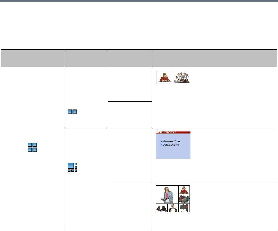
System Configuration Flags
Polycom®, Inc. 808
Example:
The following table illustrates the effect of modifying the PREDEFINED_AUTO_LAYOUT_5 flag in
conferences with fewer or more participants than the number of windows selected in the default layout.
LEGACY_EP_CONTENT_DEFAULT_LAYOUT Flag
The following table lists the value for each video layout that can be defined for the
LEGACY_EP_CONTENT_DEFAULT_LAYOUT Flag. It allows the selection of video layout that will be
displayed on the screen of the legacy endpoint when switching to Content mode.
For a list of available layouts see Available Layouts.
CS_ENABLE_EPC Flag
Endpoints that support People+Content may require a different signaling (for example, FX endpoints). For
these endpoints, manually add the flag CS_ENABLE_EPC with the value YES (default value is NO) to the
CS_MODULE_PARAMETERS tab.
Example of Predefined Auto Layouts
Flag
Set to
Possible Value
Number of
Participants Participant’s View
PREDEFINED
_AUTO_LAYOUT_5
Default =
CP_LAYOUT_1
x2VER
3 Voice activated switching displays the current
speaker in the left window of the video layout and
only the two last speakers are displayed.
7
CP_LAYOUT_I
P5
3
Voice activated switching displays the current
speaker in the large (top left) window of the video
layout.
7
Voice activated switching displays the current
speaker in the top left window of the video layout.

System Configuration Flags
Polycom®, Inc. 809
Automatic Password Generation Flags
The Collaboration Server can be configured to automatically generate conference and chairperson
passwords when the Conference Password and Chairperson Password fields are left blank.
Guidelines
●If the flag HIDE_CONFERENCE_PASSWORD is set to YES, the automatic generation of passwords
(both conference and chairperson passwords) is disabled, regardless of the settings of the flags
NUMERIC_CONF_PASS_DEFAULT_LEN and NUMERIC_CHAIR_PASS_ DEFAULT _LEN.
●The automatic generation of conference passwords is enabled/disabled by the flag
NUMERIC_CONF_PASS_DEFAULT_LEN.
●The automatic generation of chairperson passwords is enabled/disabled by the flag
NUMERIC_CHAIR_PASS_ DEFAULT _LEN.
●The automatically generated passwords will be numeric and random.
●The passwords are automatically assigned to ongoing conferences, Reservations, and Meeting
Rooms at the end of the creation process (once they are added to the Collaboration Server).
●Automatically assigned passwords can be manually changed through the Conference/Meeting
Room/Reservation Properties dialog boxes.
●Deleting an automatically created password will not cause the system to generate a new password
and the new password must be added manually or the field can be left blank.
●If a password was assigned to the conference via Microsoft Outlook using the PCO add-in, the
system does not change these passwords and additional passwords will not be generated (for
example, if only the conference password was assigned a chairperson password will not be
assigned).
●If the flag values (i.e. the password lengths) are changed, passwords that were already assigned to
conferences, Reservations, and Meeting Rooms will not change and they can be activated using the
existing passwords. Only new conferencing entities will be affected by the change.
Enabling the Automatic Generation of Passwords
The default password length is defined by the system flag NUMERIC_CONF_PASS_DEFAULT_LEN or by
one of the following Automatic Password Generation flags:
Do not enable this option in an environment that includes a Polycom DMA system.
Automatic Password Generation Flags
Flag Description
HIDE_CONFERENCE_PASSWORD NO (default) - Conference and chairperson passwords are
displayed when viewing the Conference/Meeting Room/
Reservation properties. It also enables the automatic generation
of passwords in general.
Yes - Conference and Chairperson Passwords are hidden (they
are replaced by asterisks). It also disables the automatic
generation of passwords.
System Configuration Flags
Polycom®, Inc. 810
NUMERIC_CONF_PASS_MIN_LEN Enter the minimum number of characters required for conference
passwords.
Possible values: 0 – 16.
0 (default in non-secured mode) means no minimum length.
However this setting cannot be applied when the Collaboration
Server is in Ultra Secure Mode.
9 (default in Ultra Secure Mode) Conference password must be
at least 9 characters in length.
NUMERIC_CHAIR_PASS_MIN_LEN Enter the minimum number of characters required for chairperson
passwords.
Possible values: 0 – 16.
0 (default in non-secured mode) means no minimum length.
However this setting cannot be applied when the Collaboration
Server is in Ultra Secure Mode.
9 (default in Ultra Secure Mode), Chairperson password must
be at least 9 characters in length.
NUMERIC_CONF_PASS_MAX_LEN Enter the maximum number of characters permitted for
conference passwords.
Possible values: 0 – 16 (non-secured mode) or 9 – 16 (Ultra
Secure Mode).
16 (default) - Conference password maximum length is 16
characters.
NUMERIC_CHAIR_PASS_MAX_LEN Enter the maximum number of characters permitted for
chairperson passwords.
Possible values: 0 – 16 (non-secured mode) or 9 – 16 (Ultra
Secure Mode).
16 (default) - chairperson password maximum length is 16
characters.
NUMERIC_CONF_PASS_DEFAULT_LEN This flag enables or disables the automatic generation of
conference passwords. The length of the automatically generated
passwords is determined by the flag value.
Possible values:
• 0 – 16, 6 default (non-secured mode)
• 0 and 9 – 16, 9 default (Ultra Secure Mode).
Enter 0 to disable the automatic generation of passwords.
Any value other than 0 enables the automatic generation of
conference passwords provided the flag
HIDE_CONFERENCE_PASSWORD is set to NO.
If the default is used, in non-secured mode the system will
automatically generate conference passwords that contain 6
characters.
Automatic Password Generation Flags
Flag Description
System Configuration Flags
Polycom®, Inc. 811
The default password length defined by the NUMERIC_CONF_PASS_DEFAULT_LEN or
NUMERIC_CHAIR_PASS_ DEFAULT LEN does not fall within the range defined by the minimum and
maximum length an appropriate fault is added to the Faults list.
Flags Specific to Maximum Security Environments - Ultra Secure Mode
The Collaboration Server can operate in one of two modes: Standard Security Mode or Ultra Secure Mode.
In Ultra Secure Mode the enhanced security features of the version are rigorously enforced.
The Ultra Secure Mode is enabled or disabled depending on the value of the ULTRA_SECURE_MODE
System Flag.
Ultra Secure Mode, is enabled by manually adding the ULTRA_SECURE_MODE flag to the System
Configuration and setting its value to YES.
Ultra Secure Mode Flag
NUMERIC_CHAIR_PASS_ DEFAULT _LEN This flag enables or disables the automatic generation of
chairperson passwords. The length of the automatically
generated passwords is determined by the flag value.
Possible values:
• 0 – 16, 6 default (non-secured mode)
•0 and 9 – 16, 9 default (Ultra Secure Mode).
Enter 0 to disable the automatic generation of passwords.
Any value other than 0 enables the automatic generation of
chairperson passwords provided the flag
HIDE_CONFERENCE_PASSWORD is set to NO.
If the default is used, in non-secured mode the system will
automatically generate chairperson passwords that contain 6
characters.
WARNING: Once Ultra Secure Mode is enabled it can only be undone by performing a Restore to
Factory Defaults. Also, to implement a Maximum Security environment, other Polycom products on
the network must be similarly configured.
For more information see Restoring Defaults.
Automatic Password Generation Flags
Flag Description

Polycom®, Inc. 812
Ultra Secure Mode
Ultra Secure Mode is the operating mode of the RealPresence Collaboration Server when deployed in a
Maximum Security Environment. When the MCU is set to Ultra Secure Mode, all enhanced security features
are activated and rigorously enforced.
To download and install the RMX Manager onto a workstation
»The RMX Manager specific to the installed version must be downloaded from the Support section of
the Polycom website at http://www.polycom.com/forms/rmx-sw-fed-thankyou.html
To install the RMX Manager:
1Obtain the RMX Manager specific to Version 8.1.4.J from the Polycom Software Distribution
website.
2Install the RMX Manager on the workstation:
aUsing Windows, navigate to the folder where the downloaded RMX Manager has been saved.
bDouble-click on the downloaded install file and follow the on-screen instructions to complete
the installation.
3When the install of the RMX Manager is completed, launch the RMX Manager using the Windows
Start menu.)
Warning:
Once Ultra Secure Mode is enabled it can only be disabled by performing a Restore to Factory
Defaults. In addition, to implement a Maximum Security Environment, other Polycom products on the
network must be similarly configured.
For more information see Restoring the RMX Using the USB Port in the RealPresence Collaboration
Server (RMX) 1500/2000/4000 Deployment Guide for Maximum Security Environments.
•When working in Ultra Secure Mode, the RMX Manager is the recommended option for accessing
the RMX's management console.
•Only MPMx/MPMRx media cards are supported.
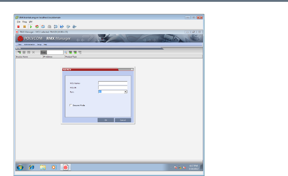
Ultra Secure Mode
Polycom®, Inc. 813
4If needed, add the MCU to the RMX Manager’s MCUs list if it was not pre-populated during
installation.
aRight-click in the RMX Manager window.
bSelect Add MCU.
cEnter the MCU Name.
dEnter the IP Address of the MCU.
eLeave the port as Port 80 until such time that the RMX is placed into Secure Mode.
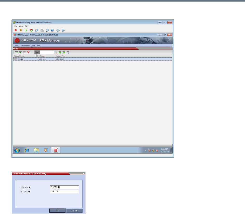
Ultra Secure Mode
Polycom®, Inc. 814
5Click OK.
6The Username and Password dialog box is displayed.
7Enter the default Username - POLYCOM and default Password – POLYCOM.
8Click OK.
Enabling Ultra Secure Mode
The Ultra Secure Mode is disabled by default and can be enabled by adding the ULTRA_SECURE_MODE
System Flag and setting its value of to YES using the Setup > System Configuration menu. Doing so
affects the ranges and defaults of other System Flags that control:
●Network Security
●User Management
●Strong Passwords
●Login and Session Management
●Cyclic File Systems alarms

Ultra Secure Mode
Polycom®, Inc. 815
For a detailed description of the installation and configuration of an MCU in a Maximum Security
Environment see First Time Installation and Configuration in the RealPresence Collaboration Server (RMX)
1500/2000/4000 Deployment Guide for Maximum Security Environments.
ULTRA_SECURE_MODE System Flag
Guidelines
●After modifying the value of the ULTRA_SECURE_MODE System Flag to YES, all Collaboration
Server users are forced to change their Login passwords.
●In previous versions the ULTRA_SECURE_MODE System Flag was named JITC_MODE:
When upgrading from a version that used the JITC_MODE System Flag, the system will
automatically create an ULTRA_SECURE_MODE System Flag and set it to the same value as
that of the JITC_MODE flag before the upgrade. The system will then delete the JITC_MODE
System Flag.
When downgrading to a version that utilizes the JITC_MODE System Flag, the administrator will
need to set the JITC_MODE flag to that of the ULTRA_SECURE_MODE flag before the
downgrade.
Modifying the Ultra Secure Mode System Flag Value
Ultra Secure Mode can be enabled by changing the value of the ULTRA_SECURE_MODE System Flag to
YES during First Entry Configuration or at any time using the Setup > System Configuration menu.
When the ULTRA_SECURE_MODE flag is set to YES, the following are not supported:
•Connection to Alternate Management
Network via LAN3 port
•SUPPORT user
•Auditor user
•Chairperson user
•Connections to External Databases
•IP Sec security protocols
•ISDN Cascade
•PCM
•SSH server
•USB key configuration
•Web link (Hyperlink in Participant Properties
dialog box)
•QoS with IPv6
•PCO (MS-Outlook)
•Video Preview
•Serial connection
•Modem connection
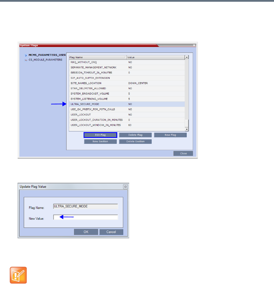
Ultra Secure Mode
Polycom®, Inc. 816
To modify the ULTRA_SECURE_MODE System flag value:
1On the Collaboration Server menu, click Setup > System Configuration.
The System Flags dialog box opens.
2Double-click or select the ULTRA_SECURE_MODE flag and click the Edit Flag button.
3In the New Value field, enter the flag’s new value - YES or NO.
4Click OK to close the Update Flag dialog box.
5Click OK to close the System Flags dialog box.
System Flags affected by Ultra Secure Mode
When the ULTRA_SECURE_MODE flag is set to YES the default and range values of the following flags
are affected.
For flag changes (including deletion) to take effect, reset the MCU. For more information see
Resetting the Collaboration Server.
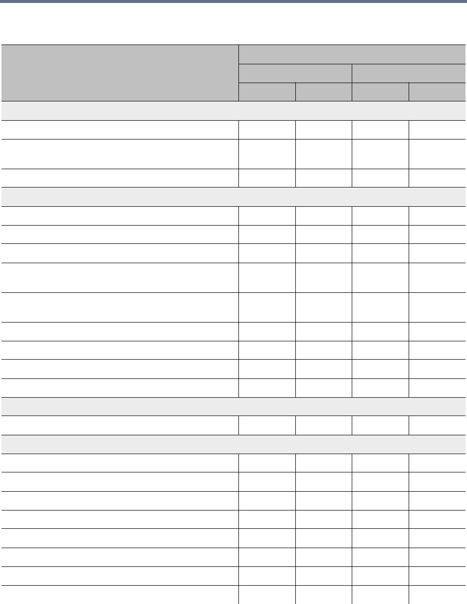
Ultra Secure Mode
Polycom®, Inc. 817
ULTRA_SECURE_MODE Flag Value – Effect on System Flags
Flag
ULTRA_SECURE_MODE Value
YES NO
Range Default Range Default
Network Security
ENABLE_ACCEPTING_ICMP_REDIRECT YES/NO NO YES/NO YES
ENABLE_SENDING_ICMP_DESTINATION_UNREACH
ABLE
YES/NO NO YES/NO YES
SEPARATE_MANAGEMENT_NETWORK YES/NO YES NO NO
Login and Session Management
APACHE_KEEP_ALIVE_TIMEOUT 1-999 15 1-999 120
LAST_LOGIN_ATTEMPTS YES/NO YES YES/NO NO
MAX_KEEP_ALIVE_REQUESTS 0 - > 0
MAX_NUMBER_OF_MANAGEMENT_SESSIONS_PER
_SYSTEM
4-80 80 4-80 80
MAX_NUMBER_OF_MANAGEMENT_SESSIONS_PER
_USER
4-80 20 4-80 10
SESSION_TIMOUT_IN_MINUTES 5-60 5 0-999 0
USER_LOCKOUT YES/NO YES YES/NO NO
USER_LOCKOUT_DURATION_IN_MINUTES 0-480 0 0-480 0
USER_LOCKOUT_WINDOW_IN_MINUTES 0-45000 60 0-45000 60
User Management
DISABLE_INACTIVE_USER 1-90 30 0-90 0
Strong Passwords
FORCE_STRONG_PASSWORD_POLICY YES YES YES/NO NO
HIDE_CONFERENCE_PASSWORD YES/NO NO YES/NO NO
HIDE_CONFERENCE_PASSWORD YES/NO NO YES/NO NO
MAX_CONF_PASSWORD_REPEATED_DIGITS 1-4 2 0-4 0
MAX_PASSWORD_REPEATED_CHAR 1-4 2 0-4 2
MIN_PASSWORD_LENGTH 15-20 15 0-20 0
MIN_PWD_CHANGE_FREQUENCY_IN_DAYS 1-7 1 0-7 0
NUM_OF_LOWER_CASE_ALPHABETIC 1-2 2 0-2 0
Ultra Secure Mode
Polycom®, Inc. 818
Certificate Management
(PKI) Public Key Infrastructure
PKI (Public Key Infrastructure) is a set of tools and policies deployed to enhance the security of data
communications between networking entities.
The implementation of PKI on the Collaboration Server has been enhanced to ensure that all networked
entities are checked for the presence of unique certificates by implementing the following rules and
procedures during the TLS negotiation:
●The Collaboration Server identifies itself with the same certificate when operating as a server and as
a client.
●The Collaboration Server’s management applications: Collaboration Server Web Client and RMX
Manager, identify themselves with certificates.
●While establishing the required TLS connection, there is an exchange of certificates between all
entities.
●Entities such as the DMA that function as both client and server within the Management Network
identify themselves with the same certificate for both their client and server functions.
●A single Certificate Repository is maintained for:
The Management Network Service.
SIP TLS Personal Certificates for each defined IP Network Service.
Trusted (CA) certificate for all TLS connections.
CRL for all TLS connections.
●SIP TLS certificates are validated against the CA.
●SIP TLS certificates are managed using CRL and Online Certificate Status Protocol (OCSP).
NUM_OF_NUMERIC 1-2 2 0-2 0
NUMERIC_CHAIR_PASS_MIN_LEN 9-16 9 0-16 0
NUMERIC_CONF_PASS_MIN_LEN 9-16 9 0-16 0
PASS_EXP_DAYS_MACHINE 365
PASSWORD_EXPIRATION_DAYS 7-90 60 0-90 0
PASSWORD_EXPIRATION_WARNING_DAYS 7-14 7 0-14 0
PASSWORD_HISTORY_SIZE 10-16 10 0-16 0
Cyclic File Systems
ENABLE_CYCLIC_FILE_SYSTEM_ALARMS YES/NO YES YES/NO NO
ULTRA_SECURE_MODE Flag Value – Effect on System Flags
Flag
ULTRA_SECURE_MODE Value
YES NO
Range Default Range Default
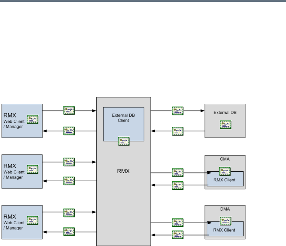
Ultra Secure Mode
Polycom®, Inc. 819
Certificate revocation mode, whether by OCSP or CRL is managed using the i setting of the
Management Network.
SIP TLS is managed using the General TLS setting.
●The following certificate file formats are supported:
PEM
DER
PKCS#7/P7B
PKCS#12PFX
The following diagram illustrates the certificate exchange during the TLS connection procedure.
Adding Certificates to the Certificate Repository
To access the Certification Repository:
»In the Collaboration Server Web Client, click Setup > RMX Secured Communication >
Certification Repository.
The Certification Repository dialog box contains tabs that display the following lists:
Trusted Certificates
Personal Certificates (Management and Signaling Certificates)
CRL (Certificate Revocation List)
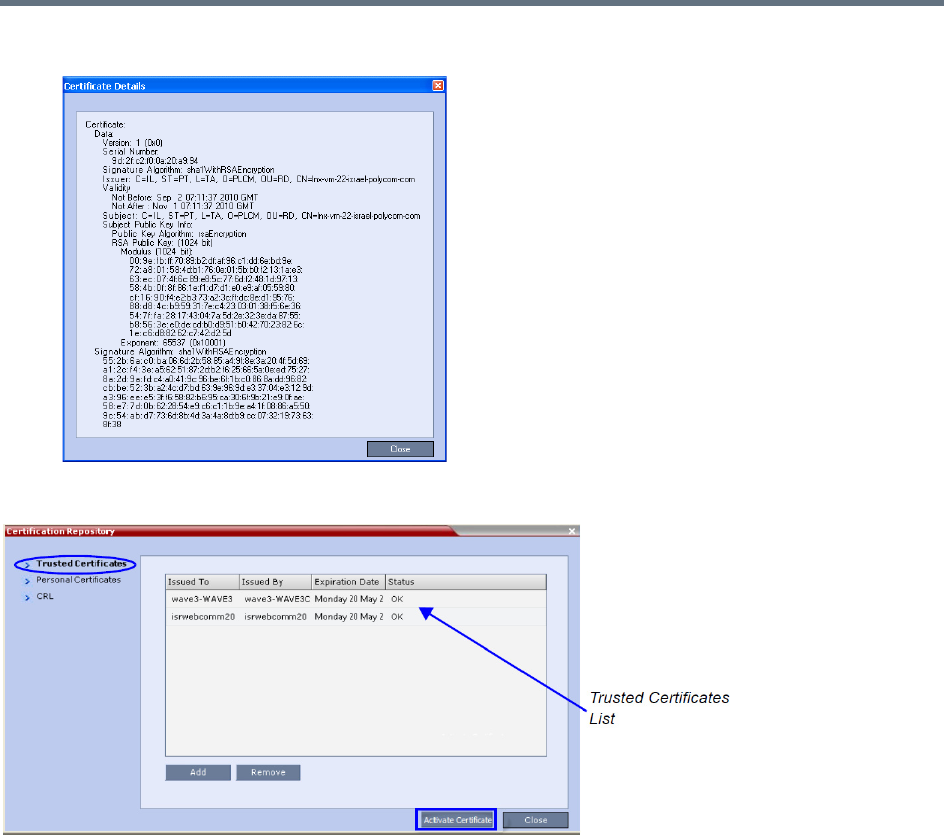
Ultra Secure Mode
Polycom®, Inc. 820
Double-clicking on a certificate in any if the displayed lists, displays the certificate’s properties:
Trusted Certificates
By clicking the column headers the Trusted Certificates can be sorted by:
●Issued To
●Issued By
●Expiration Date
●Status
To add a certificate to the repository:
Repeat steps 1 - 4 for each certificate you wish to add to the Certification Repository.
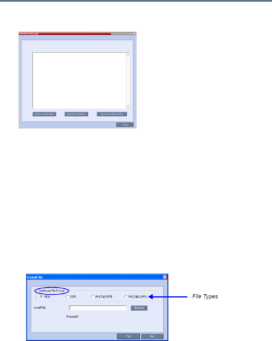
Ultra Secure Mode
Polycom®, Inc. 821
1In the Trusted Certificates tab click the Add button.
The Send Certificate dialog box is displayed.
2Send the certificate to the Collaboration Server.
Two options are available for sending the certificate to the Collaboration Server:
Paste Certificate and Send Certificate
Use this option if the certificate has been received from the Certification Authority in text format.
Send Certificate File
Use this option if the certificate has been received from the Certification Authority in file format.
Paste Certificate and Send Certificate
After you have received the certificate from the Certificate Authority:
aCopy (Ctrl + C) the certificate information from the Certificate Authority’s e-mail to the clipboard.
bClick Paste Certificate to paste the clipboard content into the Send Certificate dialog box.
cClick the Send Certificate button to send the certificate to the Collaboration Server.
Send Certificate File
After you have received the certificate file from the Certificate Authority:
dClick Send Certificate File.
The Install File dialog box is displayed.
eSelect the Certificate File Format: PEM, DER, PKCS#7/P7B or PKCS#12PFX.
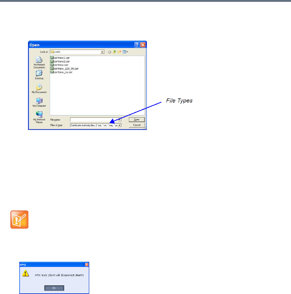
Ultra Secure Mode
Polycom®, Inc. 822
fEnter the certificate file name in the Install File field or click the Browse button.
The Open file dialog box is displayed. The files are filtered according to the file type selected in
Step e.
gEnter the certificate file name in the File name field or click to select the certificate file entry in the
list.
hClick the Open button.
iIn the Install File dialog box, click the Yes button to proceed.
The certificate is added to the Trusted Certificate List in the Certification Repository.
3If there are additional Trusted Certificates to be added to the Certification Repository, repeat steps
1 - 2, otherwise click the Update Repository button to complete Trusted Certificate / CRL
installation.
When the Activate Certificate button is clicked, all added Trusted Certificates and CRLs are installed
and the Collaboration Server displays a disconnection confirmation dialog box.
4Click OK.
5Login to the Collaboration Server to proceed with further management tasks.
Trusted Certificates added to the Certification Repository are not automatically activated. They remain in
the Trusted Certificates List until the Activate Certificate button is clicked, at which time all Trusted
Certificates in the list are activated simultaneously.
Before clicking the Activate Certificate button ensure that all CRLs have also been added to the
Certification Repository.

Ultra Secure Mode
Polycom®, Inc. 823
Personal Certificates
Default Management and Default IP Network Service certificates can be viewed in the Personal Certificates
dialog box.
They are listed alongside the service to which they are attached. By clicking the column headers the Trusted
Certificates can be sorted by:
●Network Service
●Issued To
●Issued By
●Expiration Date
●Status
To add a Personal Certificate to the Certificate Repository:
1In the Certification Repository - Personal Certificates dialog box select the Network Service.
2Click the Add button.
The Add dialog box is displayed with the configured parameters of the selected Network Service
filled in.
3Select the Certificate Method. (Default is CSR)
Only CSR can be selected for the Default Management Network Service.
CSR or PFX/PEM can be selected for IP Network Services.
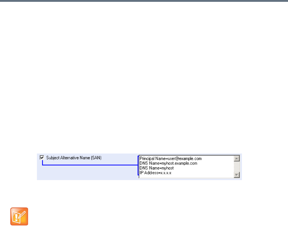
Ultra Secure Mode
Polycom®, Inc. 824
4Optional. If CSR was selected as the Certificate Method:
aClick Create Certificate Request.
The Create Certificate Request dialog box is displayed with the Common Name field filled in.
bComplete the Certificate Request fields.
The two additional fields are defined as:
Subject Alternative Name (SAN) - This field is required when using EAP-TLS in conjunction
with a Network Policy Server (MS-NPS). It allows the optional inclusion of:
- Principle Name
- DNS Name:
Long – FQDN
Short - Host only
- IP Address (IPv4 and IPv6)
When the Subject Alternative Name (SAN) check box is selected the input box becomes
active, allowing the user to modify the example values provided, to match local certificate
requirements and delete those that are not applicable.
The user can add up to 20 different SANs. If an incorrect SAN type is entered, an error
message, Unsupported SAN type, is displayed when the Send Details button is clicked.
Hash Method - Select the output value for the Secure Hash Algorithm:
- SHA-256 the output value is 256 bits.
- SHA-1 the output value is 160 bits.
For backward compatibility, with previous versions, either SHA-1 or SHA-256 can be selected
as the hash algorithm used in the creation of CSRs (Certificate Signing Requests).
5Click Send Certificate.
For all certificates, both Management and SIP TLS:
●Once the certificate is sent a message is displayed indicating successful installation of the certificate
and the new certificate replaces the old certificate.
●If the certificate installation fails the old certificate continues to function and a message is displayed
indicating one of the following the reasons for the failure:
Invalid password.
Certificate expired.
Certificate DNS name does not match Collaboration Server (service) DNS name.
Chain is not trusted
The SAN field option - DNS Name (FQDN) is not used for Machine Account validation. For example,
the DMA will not validate the Collaboration Server unless the FQDN field in the User Properties
dialog box is correctly filled in.
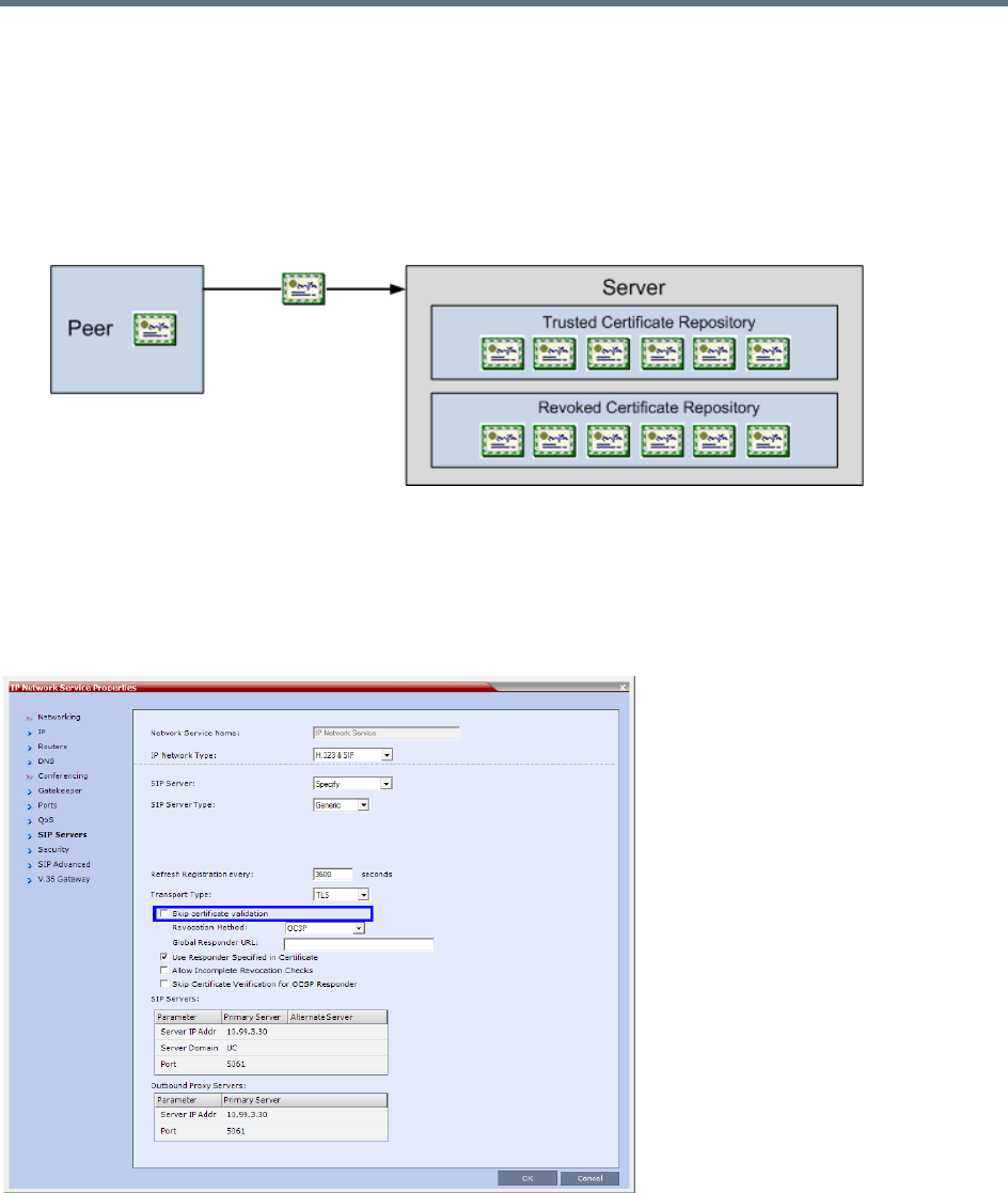
Ultra Secure Mode
Polycom®, Inc. 825
General - <Error message from the SSL library>.
Certificate Validation
The credentials of each certificate received from a networked peer are verified against a repository of
trusted certificates. Each networked entity contains a repository of trusted certificates. The digital signature
of the certificate’s issuing authority is checked along with the certificate’s expiration date.
Validation of peer SIP TLS certificates against one or several installed CA certificates can be enabled or
disabled for the Default Management and each defined IP Service by selecting or clearing the Skip
certificate validation check box.
The check box is checked by default to Skip certificate validation for user logging session and no validation
of expiration, CA signature or CRL/OCSP checking is performed.
Clearing the check box enables full validation requires that there be at least one CA certificate in the
certificate repository, failing which a message At least one CA certificate should be
installed is displayed.
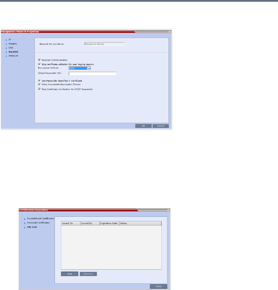
Ultra Secure Mode
Polycom®, Inc. 826
If the Secured Communication option is unchecked in the Management Network - Security dialog box all
Certificate Validation and Revocation fields are disabled.
CRL (Certificate Revocation List)
A CRL contains a summary of the installed Certificate Revocation Lists.
By clicking the column headers the Certificate Revocation List can be sorted by:
●Issued To
●Issued By
●Expiration Date
●Status
If the CRL List is not valid for any reason an Active Alarm is created and a message is displayed. The
Collaboration Server Web Client/RMX Manager connection to the Collaboration Server is not disabled.
Adding a CRL
Repeat steps 1 - 5 for each CRL that is to be added to the Certification Repository.
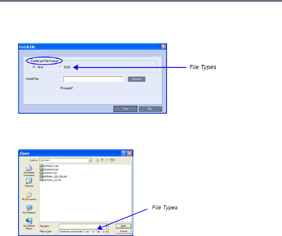
Ultra Secure Mode
Polycom®, Inc. 827
To add a CRL to the repository:
1In the CRL List dialog box, click the Add button.
The Install File dialog box is displayed.
2Select the Certificate File Format: PEM or DER.
3Enter the certificate file name in the Install File field or click the Browse button.
The Open file dialog box is displayed. The files are filtered according to the file type selected in Step e.
4Enter the Certificate file name in the File name field or click to select the certificate file entry in the
list.
5Click the Open button.
The certificate is added to the CRL List in the Certification Repository.
If there are additional CRLs to be added to the Certification Repository, repeat steps 1 - 5, otherwise
click the Activate Certificate button to complete CRL / Trusted Certificate installation.
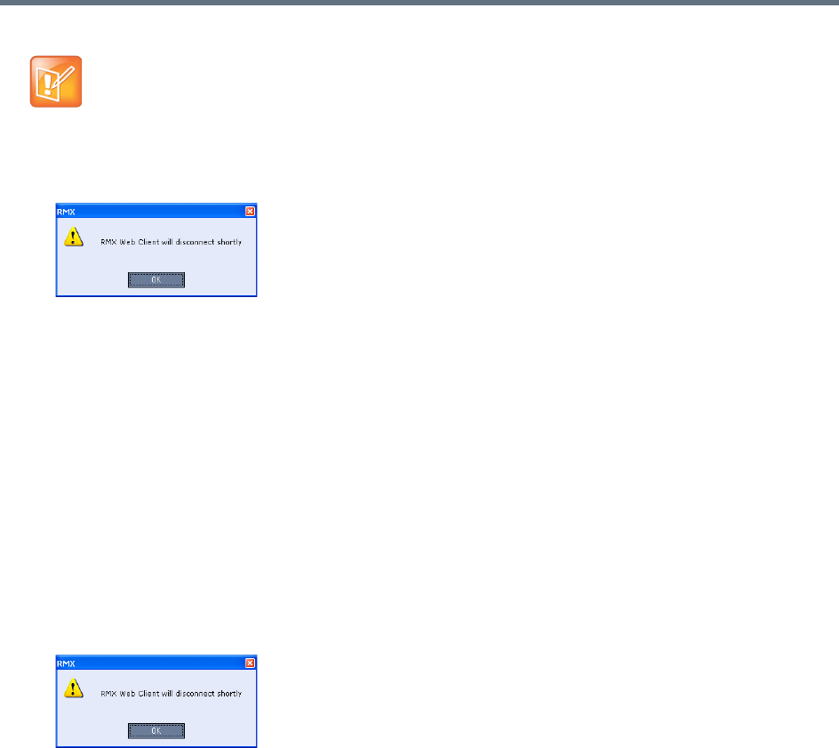
Ultra Secure Mode
Polycom®, Inc. 828
When the Activate Certificate button is clicked, all added Trusted Certificates and CRLs are installed
and the Collaboration Server displays a disconnection confirmation dialog box.
6Click the OK button.
7Login to the Collaboration Server to proceed with further management tasks
CRLs added to the Certification Repository are not automatically activated. They remain in the CRL
List until the Activate Certificate button is clicked, at which time all CRLs in the list are activated
simultaneously.
Removing a CRL
To remove a CRL:
1In the certificate list, select the CRL List to be removed.
2Click the Remove button.
The certificate is removed and the Collaboration Server displays a disconnection confirmation dialog
box.
3Click the OK button.
Login to the Collaboration Server to proceed with further management tasks.
Before clicking the Activate Certificate button ensure that all Trusted Certificates have also been
added to the Certification Repository.
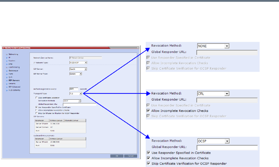
Ultra Secure Mode
Polycom®, Inc. 829
Certificate Revocation
Certificate Revocation of IP Network and peer SIP TLS certificates for each defined IP Service can be
enabled, disabled and configured:
Revocation Method
One of three Certificate Revocation Methods can be selected:
●NONE (Default) - Certificate Revocation is not implemented.
●CRL - Requires at least one CRL file be installed, failing which an error message, At least one CRL
should be installed, is displayed.
●OCSP - When selected, additional configuration options are displayed.
Global Responder URL
The format of the URL is validated and must be of the format:
http(s)://responder.example.com/ocsp
The URL can be either http or https.
If the Global Responder URL does not respond an Active Alarm is raised.
Use Responder Specified in Certificate
The default for this check box is unchecked.
If the check box is checked Responder URL is taken from the certificate. If the certificate does
not contain a Responder URL, the Global Responder URL is used.
If the check box is unchecked the Global Responder URL is used. If the Global Responder
URL is incorrectly configured a message, Global responder URL must be configured, is
displayed.
Allow Incomplete Revocation Checks
If OCSP is selected:
If the check box is checked and the Global Responder or the Responder Specified in the
Certificate does not respond for any reason the certificate is not considered revoked.

Ultra Secure Mode
Polycom®, Inc. 830
If the check box is unchecked and the Global Responder or the Responder Specified in the
Certificate does not respond for any reason the certificate is considered revoked.
If CRL is selected:
If the check box is checked and the CRL of the specific CA is not loaded, all Certificates are
the CA are not considered revoked.
If the check box is unchecked and the CRL of the specific CA is not loaded, all Certificates
are the CA are considered revoked.
Skip Certificate Validation for OSCP Responder
No Certificate Validation is performed.
●System Flag:
Should intermittent login problems occur when logging in to the Collaboration Server’s Management
Network, the OCSP_RESPONDER_TIMEOUT system flag can be manually added to system.cfg
and its value set to the number of seconds the Collaboration Server is to wait for an OCSP response
from the OCSP Responder before failing the connection.
Default: 3 (seconds)
Range: 1-20 (seconds)
Self-signed Certificate
In compliance with UC APL requirements, PKI Self-signed Certificates are supported for the both the Default
Management and IP Network Services.
A mixture of Self-signed and CA-signed Certificates is supported, however a CA-signed certificate will
always override a Self-signed Certificate.
Self-signed Certificate Creation
Self-signed Certificates are created during:
●Initial system start-up before any CA-signed Certificates have been installed.
●IP Network Services creation.
●Network Services updates that result in Host Name changes.
●Daily validity checks of Self-signed Certificates.
●Backup and Restore of the system configuration
Self-signed Certificate field values are automatically inserted when the certificate is created:
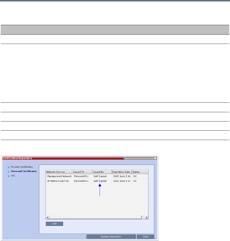
Ultra Secure Mode
Polycom®, Inc. 831
Self-signed Certificates are indicated in the Certification Repository - Issued By field.
Self-signed Certificate Field Values - Creation
Field Value
Signature Algorithm SHA1
Issuer / Issued To Service Host Name
Both the Issuer and Issued To fields have the same values.
CN = host name of the service name
DC = Polycom
OU = Self Signed Certificate
O = Polycom MCU
Note: The value of CN is derived from the IP Network Service Name, while the
values of DC, OU and O are hard coded.
For a full description of these fields see RFC 5280.
Valid from Date of creation
Valid to Date of creation + 10 years
Subject (Common Name) Service Host Name
Public Key 2048 bits

Ultra Secure Mode
Polycom®, Inc. 832
Emergency CRL (Certificate Revocation List) Update
Administrators maintaining RMX systems are required to perform an update of the CRLs used on the
systems within the validity period of the current CRLs.
Should the current CRLs expire; the system will not allow administrators to login and perform administrative
tasks using the RMX Web Client or RMX Manager.
The Emergency CRL Update procedure disables client certificate validation enabling an administrator to
access the system and install an updated CRL file without having to perform a full system rebuild.
To perform an Emergency CRL Update procedure:
Step 1: Download and save the updated CRL files from the CA Server.
Step 2: Disable Secured Communications Mode.
Step 3: Open the Certification Repository and update the CRL files.
Step 5: Update the Repository.
Step 6: Re-connect to the RMX.
Step 7: Re-enable Secured Communications Mode.
Step 1: Download and save the updated CRL files from the CA Server
These files are saved on the workstation.
Step 2: Disable Secure Communications mode
aConnect a USB keyboard or mouse to the USB port of RMX.
The USB port locations for RMX 1500/2000/4000 are shown in USB Restore.
bPower the RMX Off and then On using the power switch and allow the RMX to complete its
startup.
System restart can take 5 - 10 minutes, depending on the RMX’s configuration.
Using the RMX Manager:
cIn the MCUs list, select the RMX to be updated.
dIn MCU Properties, change the Port number from 443 to 80.
This procedure must only be performed on a secured network as the system must disable the client
certificate validation process resulting in management traffic being sent over the network without the
use of SSL encryption.
The RMX must be powered on before starting this procedure.
The RMX supports the use of PEM and DER formats.
Take note of the format you download as you will need to make a selection later in this process when
uploading the new CRL files.
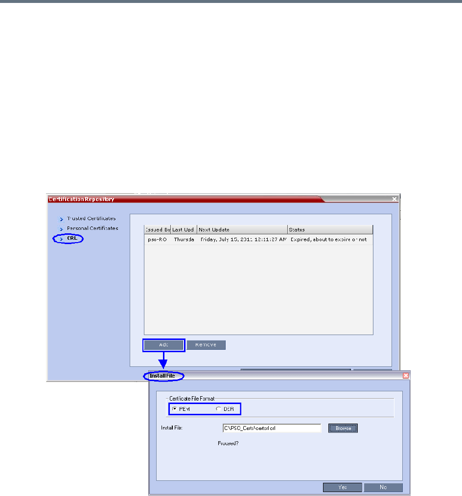
Ultra Secure Mode
Polycom®, Inc. 833
eClick OK.
fIn the MCUs list, select the RMX to be updated.
gRight-click in the MCUs list entry and select Connect.
hClick Accept to accept the warning banner.
iEnter an administrator Username and Password.
jClick OK.
Step 3: Open the Certification Repository and Update the CRL files
aOn the RMX menu, click Setup > RMX Secured Communication > Certification Repository.
bClick the CRL tab.
cClick Add.
dIn the Install File dialog box, select the DER or PEM format depending on which file format was
chosen in Step 1 of this procedure.
eClick the Browse button to navigate to the folder on the workstation where you saved the CRL
files in Step 1 of this procedure.
fSelect the CRL file that you want to upload.
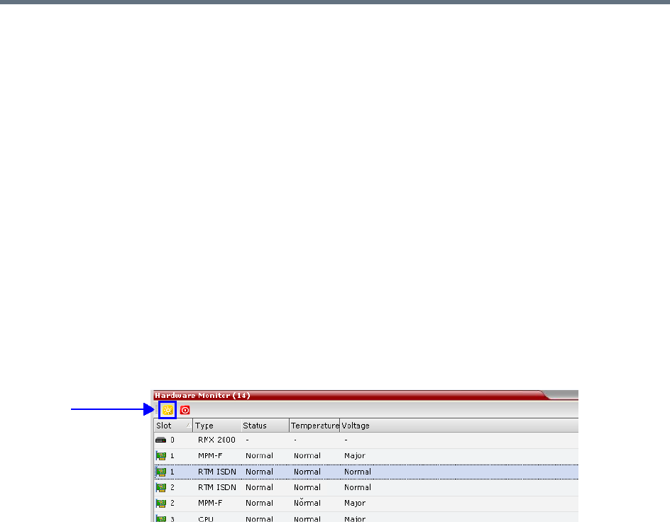
Ultra Secure Mode
Polycom®, Inc. 834
gClick Yes to proceed.
The system checks the CRL file and displays a message that the certificate was loaded
successfully.
hRepeat Steps d through f until all of the required CRL files has been updated.
Step 4: Update the repository.
When all the CRL files have been updated as described in Step 3.
a Click Update Repository.
A repository update confirmation message is displayed.
bClick OK to update the repository.
Step 5: Re-connect to the RMX.
aRemove the USB device that was connected in Step 2a.
bRestart the RMX.
cIn the RMX Management pane, click the Hardware Monitor button.
The Hardware Monitor pane is displayed.
dClick the Reset button.
The RMX restarts. System restart can take 5 - 10 minutes, depending on the RMX’s configuration.
Using the RMX Manager:
eIn the MCUs list, select the RMX to be updated.
fRight-click in the MCUs list entry and select Connect.
gClick Accept to accept the warning banner.
hEnter an administrator Username and Password.
iClick OK.
Step 6: Re-enable Secured Communications Mode.
Using the RMX Manager:
aIn the RMX Management pane, click the IP Network Services button. (Depending on the RMX
Manager configuration, you may have to click Rarely Used first.)
bIn the IP Network Services list pane, double-click Management Network.
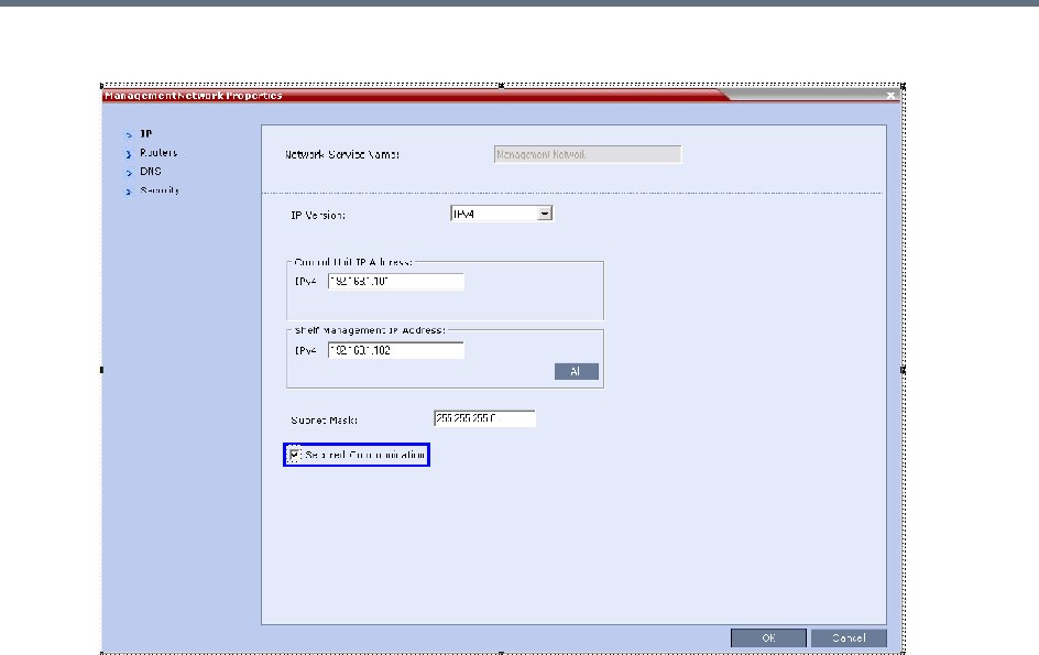
Ultra Secure Mode
Polycom®, Inc. 835
The Management Network Properties dialog box is displayed.
cSelect the Secured Communication check box.
dClick OK.
A message informs you that your session will be disconnected and that you must re-connect the
RMX using https in the browser URL.
eClick OK.
A system restart confirmation message is displayed.
fClick Yes to restart the RMX.
The RMX restarts. System restart can take 5 - 10 minutes, depending on the RMX’s configuration.
gIn the MCUs list, select the RMX to be updated.
hIn MCU Properties, change the Port number from 80 to 443.
iClick OK.

Ultra Secure Mode
Polycom®, Inc. 836
SIP TCP Keep-Alive
In compliance with UC APL requirements, the NAT Keep Alive method has been enhanced according to
IETF RFC 5626 and For a full description of Keep Alive see IETF RFC 5626 and IETF RFC 6223.
Keep Alive behavior is defined for each IP Network Service and can be modified by adding the following
system flags and modifying their values according to System Flags: SIP_TCP_KEEP_ALIVE_TYPE /
BEHAVIOR. For more information see IP Network Services.
System Flags - SIP_TCP_KEEP_ALIVE_TYPE / BEHAVIOR
Flag Possible Flag Values
SIP_TCP_KEEP_ALIVE_TYPE NONE
•No Keep Alive messages are sent.
MS (Default when Microsoft SIP Server Type is selected for the Network
Service).
•Keep Alive messages are sent only after successful registration.
•A Ping response is not expected.
RFC5626
•In the SIP Header, the Flow-Timer Header Field is mandatory.
•Keep Alive messages are sent only after successful registration. A Ping
response is expected and if none is received, the value of the
SIP_TCP_KEEP_ALIVE_BEHAVIOR system flag is checked.
If its value is
DO_NOT_RE_REGISTRATION_WHEN_NO_PONG_RESPONSE:
For a Register Dialog, a Reregister Message is sent. There is no
disconnection.
For a Call Dialog, no further messages are sent. There is no
disconnection.
If its value is RE_REGISTRATION_WHEN_NO_PONG_RESPONSE:
Both Register and Call Dialogs are disconnected.
SIP_TCP_KEEP_ALIVE_TYPE RFC6223
•Behavior is the same as for RFC5626 with the following differences:
In the SIP Header, the Via Header “keep” is mandatory.
In the SIP Header, the Flow-Timer Header Field is optional.
PLCM (Default when Generic SIP Server Type is selected for the Network
Service).
•For Call and successful Register Dialogues:
Two CR LF character sequences are sent
No Ping response is expected
Ultra Secure Mode
Polycom®, Inc. 837
SIP_TCP_KEEP_ALIVE_BEHAVIOR If the value of the System Flag, SIP_TCP_KEEP_ALIVE_TYPE=
RFC5626 or RFC6223 and no Ping is received, the value of this System
Flag is checked.
Possible Values:
• RE_REGISTRATION_WHEN_NO_PONG_RESPONSE
• DO_NOT_RE_REGISTRATION_WHEN_NO_PONG_RESPONSE
(Default)
For a full description see the description for the
SIP_TCP_KEEP_ALIVE_TYPE flag (above).
System Flags - SIP_TCP_KEEP_ALIVE_TYPE / BEHAVIOR
Flag Possible Flag Values
Ultra Secure Mode
Polycom®, Inc. 838
Keep Alive Frequency
The Keep Alive frequency is set by the SIP Server using the Via Header keep and Flow Timer fields of the
SIP Header.
If the Collaboration Server is functioning as the server, the Keep Alive frequency is set according to the hard
coded values listed in the following table.
User and Connection Management
Chairperson and Auditor user Authorization Levels are not supported in Ultra Secure Mode.
In Ultra Secure Mode (ULTRA_SECURE_MODE=YES), Users can be automatically disabled or locked out
by the system when they do not log into the Collaboration Server application for a predefined period or if
their login session does not meet Enhanced Security requirements. Users can be manually disabled by the
administrator.
An administrator can enable a User who was disabled automatically by the system (in the Ultra Secure
Mode) or manually by the administrator.
Additional security measures can be implemented in the Collaboration Server by setting the appropriate
system flags. These measures control the system users, the user connections to the MCU and the user
login process.
Managing system users includes:
●User types that are not supported when the Ultra Secure Mode is enabled.
●Disabling and enabling system Users.
●Renaming Users.
●Disabling inactive users.
Managing the user login process includes:
●Implementing Strong Passwords.
●Implementing password re-use / history rules.
●Defining password aging rules.
●Defining password change frequency.
●Forcing password change.
Keep Alive - Frequency
Field Seconds
SIP_TCP_KEEP_ALIVE_DISABLE None
SIP_TCP_KEEP_ALIVE_MS 300
SIP_TCP_KEEP_ALIVE_5626 60
SIP_TCP_KEEP_ALIVE_6223
SIP_TCP_KEEP_ALIVE_PLCM

Ultra Secure Mode
Polycom®, Inc. 839
●Conference and Chairman Passwords.
●Locking out User.
●Displaying the User Login record.
Controlling the user sessions includes:
●Limiting the maximum number of concurrent user sessions.
●User session timeout.
●Limiting the maximum number of users that can connect to the system.
Managing the System Users
When the MCU is configured to Ultra Secure Mode (the ULTRA_SECURE_MODE is set to YES), the
following user management rules are automatically enforced:
User Types
●Auditor and chairperson user types are not supported.
●The SUPPORT user type is not allowed. If it exists, this user type is removed when the
ULTRA_SECURE_MODE is set to YES and the system is restarted.
The Audit files can be retrieved by the Administrator User.
Disabling/Enabling Users
●An administrator can disable a user or enable a disabled user, including administrators.
●The last administrator cannot be disabled.
For more information see Disabling Inactive Users.
Renaming Users
●An administrator can rename any user, including administrators.
●A renamed user is considered by the system to be a new user and is forced to change his/her
password.
Disabling Inactive Users
Users can be automatically disabled by the system when they do not log into the Collaboration Server
application for a predefined period. When the Collaboration Server is configured to Ultra Secure Mode this
option is enforced.
●To enable this option, the DISABLE_INACTIVE_USER system flag to a value between 1 to 90. This
value determines the number of consecutive days a user can be inactive before being disabled.
When flag value is set to 0 (default in standard security environment), this option is disabled.
The flag value is automatically set to 30 days when Ultra Secure Mode is enforced.
●The user is marked as disabled but is not deleted from the system administrator/operator database.
●The user remains disabled until re-enabled by an administrator.
●If a disabled user attempts to Login, an error message, Account is disabled, is displayed.
●The last remaining administrator cannot be disabled.

Ultra Secure Mode
Polycom®, Inc. 840
Managing the User Login Process
Implementing Strong Passwords
Strong Passwords can be implemented for logging into the Collaboration Server management applications.
They can be implemented when the system is in standard security mode or when in Ultra Secure Mode.
The FORCE_STRONG_PASSWORD_POLICY System Flag, which enables or disables all password
related flags cannot be set to NO and all Strong Passwords rules are automatically enabled and cannot be
disabled when the ULTRA_SECURE_MODE System Flag is set to YES.
If an administrator modifies any of the Strong Passwords flag settings, all users are forced to perform the
password change procedure, ensuring that all user passwords conform to the modified Strong Passwords
settings.
Administrators can change passwords for users and other administrators. When changing passwords for
him/herself, other administrators or other users, the administrator is required to enter his/her own
administrator’s password.
Strong Passwords rules are enforced according to the settings of the various Strong Passwords flags as
described in System Flags affected by Ultra Secure Mode. Default settings of these flag change according
to the system security mode.
Password Character Composition
●When the FORCE_STRONG_PASSWORD_POLICY System Flag is set to YES:
A Strong Password must contain at least one of all of the following character types:
Upper case letters
Lower case letters
Numbers
Special characters: @ # $ % ^ & * ( ) _ - = + | } { : " \ ] [ ; / ? > < , . (space) ~
●When the FORCE_STRONG_PASSWORD_POLICY and ULTRA_SECURE_MODE System Flags
are set to YES:
A Strong Password must contain at least two of all of the following character types:
Upper case letters
Lower case letters
Numbers
Special characters: @ # $ % ^ & * ( ) _ - = + | } { : " \ ] [ ; / ? > < , . (space) ~
●Passwords cannot contain the User ID (User Name) in any form. Example: A user with a User ID,
ben, is not permitted to use “123BeN321” as a password because BeN is similar to the User ID.
●Passwords cannot contain more than four digits in succession.
When the strong password option is enabled and the password does not meet the Strong Password
requirements the error Password characteristics do not comply with Enhance Security
requirements is displayed.

Ultra Secure Mode
Polycom®, Inc. 841
Password Length
The length of passwords is determined by the value of the MIN_PASSWORD_LENGTH System Flag.
●Possible flag values are between 0 and 20.
●A System Flag value of 0 means this rule is not enforced, however this rule cannot be disabled when
the Collaboration Server is in Ultra Secure Mode.
●In Ultra Secure Mode, passwords must be at least 15 characters in length (default) and can be up to
20 characters in length.
●If the MIN_PASSWORD_LENGTH flag is enabled and the password does not meet the required
length the error Password is too short is displayed.
If the minimum password length is increased, valid pre-existing passwords remain valid until users are
forced to change their passwords.
Implementing Password Re-Use / History Rules
Users are prevented from re-using previous passwords by keeping a list of previous passwords. If a
password is recorded in the list, it cannot be re-used. The list is cyclic, with the most recently recorded
password causing the deletion of the oldest recorded password.
●The number of passwords that are recorded is determined by the value of the
PASSWORD_HISTORY_SIZE System Flag. Possible values are between 0 and 16.
●A flag value of 0 means the rule is not enforced, however this rule cannot be disabled when the
Collaboration Server is in Ultra Secure Mode.
●In Ultra Secure Mode, at least 10 passwords (default) and up to 16 passwords must be retained.
If the password does not meet this requirement, the error New password was used recently is
displayed.
Defining Password Aging
The duration of password validity is determined by the value of the PASSWORD_EXPIRATION_DAYS
System Flag.
●Passwords can be set to be valid for durations of between 0 and 90 days.
●If the System Flag is set to 0, user passwords do not expire. The System Flag cannot be set to 0 when
the Collaboration Server is in Ultra Secure Mode.
●In Ultra Secure Mode, the minimum duration can be set to 7 days and the default duration is 60 days.
The display of a warning to the user of the number of days until password expiration is determined by the
value of the PASSWORD_EXPIRATION_WARNING_DAYS System Flag.
●Possible number of days to display expiry warnings is between 0 and 14.
●If the System Flag is set to 0, password expiry warnings are not displayed. The System Flag cannot
be set to 0 when the Collaboration Server is in Ultra Secure Mode.
●In Ultra Secure Mode, the earliest warning can be displayed 14 days before passwords are due to
expire and the latest warning can be displayed 7 days before passwords are due to expire (default
setting).
●If a user attempts to log in after his/her password has expired, an error is displayed: User must
change password.

Ultra Secure Mode
Polycom®, Inc. 842
Maximum Repeating Characters
There are two separate flags that control the maximum number of repeated characters permitted in a
password, one for the user password and one for the chairperson (conference) password.
●MAX_PASSWORD_REPEATED_CHAR allows the administrator to configure the maximum number
of consecutive repeating characters to be allowed in a user password.
Range: 1 - 4
Default: 2
●MAX_CONF_PASSWORD_REPEATED_DIGITS allows the administrator to configure the maximum
number of consecutive repeating digits to be allowed in a conference password.
Range: 1 - 4
Default: 2
Defining Password Change Frequency
The frequency with which a user can change a password is determined by the value of the
MIN_PWD_CHANGE_FREQUENCY_IN_DAYS System Flag. The value of the flag is the number of days
that users must retain a password.
●Possible retention period is between 0 and 7 days. In Ultra Secure Mode the retention period is
between 1 (default) and 7.
●If the System Flag is set to 0, users do not have to change their passwords. The System Flag cannot
be set to 0 when the Collaboration Server is in Ultra Secure Mode.
●If a user attempts to change a password within the time period specified by this flag, the error
Password change is not allowed before defined min time has passed is displayed.
An administrator can assign a new password to a user at any time.
Forcing Password Change
When the system is in Ultra Secure Mode the user is forced to change his/her password as follows:
●After modifying the value of the ULTRA_SECURE_MODE System Flag to YES, all Collaboration
Server users are forced to change their Login passwords.
●When an administrator creates a new user, the user is forced to change his/her password on first
Login.
●If an administrator changes a users User ID name, that user is forced to change his/her password on
his/her next Login.
●If a user logs in using his/her old or default password, the Login attempt will fail. The error User must
change password is displayed.
●Changes made by the administrator to any of the Strong Password enforcement System Flags render
users’ passwords invalid.
Example: A user is logged in with a fifteen character password. The administrator changes the value of the
MIN_PASSWORD_LENGTH System Flag to 20.
The next time the user tries to log in, he/she is forced to change his/her password to meet the updated
Strong Password requirements.
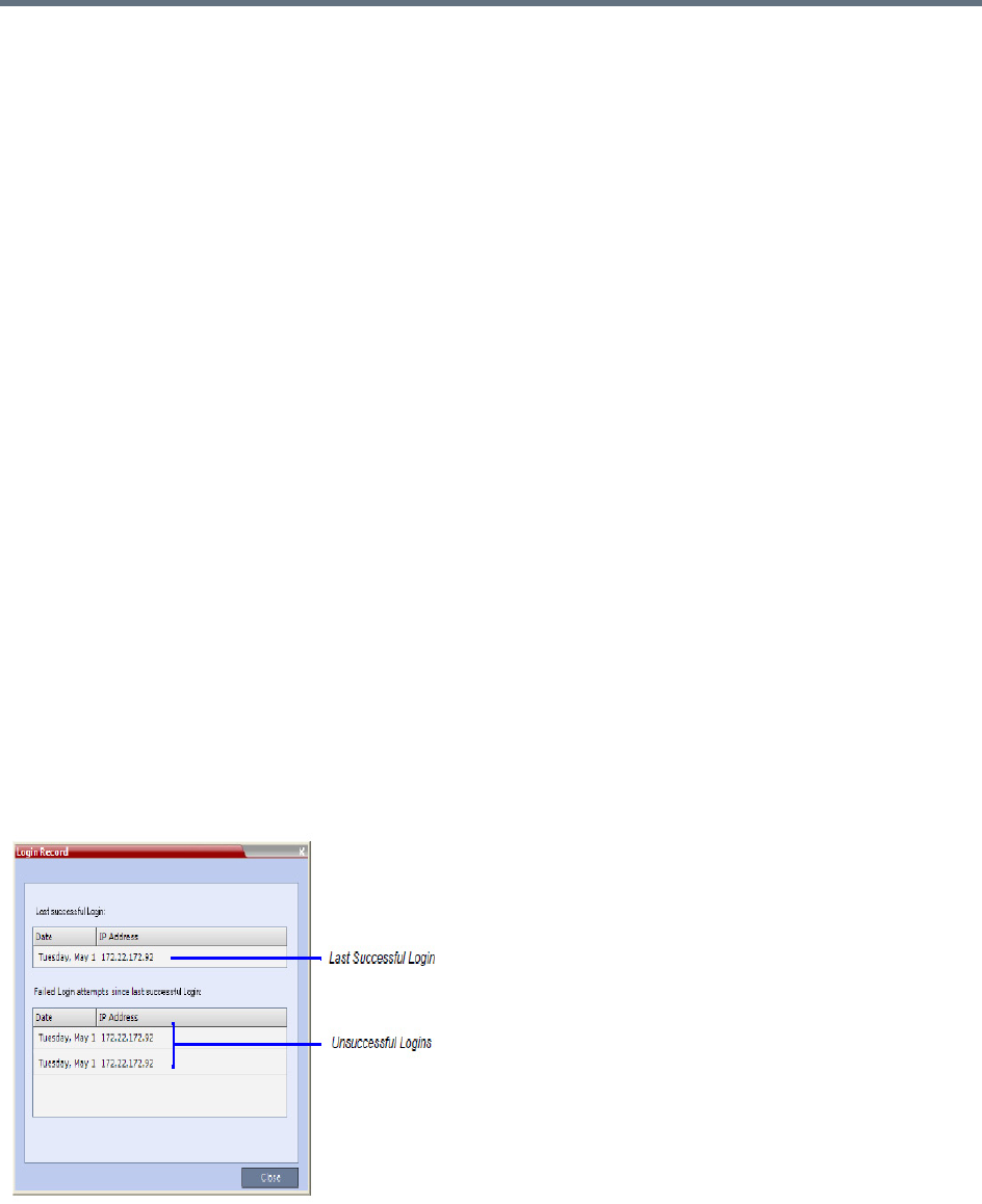
Ultra Secure Mode
Polycom®, Inc. 843
Temporary User Lockout
When the ULTRA_SECURE_MODE System Flag is set to YES, Temporary User Lockout is implemented
as a defense against Denial of Service Attacks or Brutal Attacks. Such attacks usually take the form of
automated rapid Login attempts with the aim of gaining access to or rendering the target system (any
network entity) unable to respond to users.
If a user tries to log in to the system and the Login is unsuccessful, the user’s next Login attempt only
receives a response from the Collaboration Server after 4 seconds.
User Lockout
User Lockout can be enabled to lock a user out of the system after three consecutive Login failures with
same User Name. The user is disabled and only the administrator can enable the user within the system.
User Lockout is enabled when the USER_LOCKOUT System Flag is set to YES.
If the user tries to login while the account is locked, the error message Account is disabled is
displayed.
User Lockout is an Audit Event.
A system reset does not reset the Login attempts counter.
The time period during which the three consecutive Login failures occur is determined by the value of the
USER_LOCKOUT_WINDOW_IN_MINUTES System Flag. A flag value of 0 means that three consecutive
Login failures in any time period will result in User Lockout. Value can be between 0 and 45000.
The duration of the Lockout of the user is determined by the value of the
USER_LOCKOUT_DURATION_IN_MINUTES System Flag. A flag value of 0 means permanent User
Lockout until the administrator re-enables the user within the system. Value can be between 0 and 480.
User Login Record
The system can display a record of the last Login of the user. It is displayed in the Main Screen of the
Collaboration Server Web Client or Collaboration Server Manager. The user Login Record display is
enabled when the LAST_LOGIN_ATTEMPTS System Flag is set to YES.
Both lists display the:
●Date and Time of the Login attempt.

Ultra Secure Mode
Polycom®, Inc. 844
●IP Address of the workstation initiating the Login attempt.
The list of unsuccessful Logins can contain up to ten records.
Failed Login attempts are written to the system Log Files and are recorded as Audit Events. The Audit files
can be retrieved by the Administrator User.
Controlling User Sessions
Management Sessions per System
It is possible for a several users to simultaneously log in to the Collaboration Server and initiate
management sessions from different instances of the Collaboration Server Web Client or Collaboration
Server Manager that are running on a single or several workstations.
The maximum number of concurrent management sessions (http and https connections) per system is
determined by the value of the MAX_NUMBER_OF_MANAGEMENT_SESSIONS_PER_SYSTEM System
Flag.
Any attempt to exceed the maximum number of management sessions per system results in the display of
an error message: Maximum number of permitted user connections has been exceeded.
New connection is denied.
The log in attempt is recorded as an Audit Event.
Sessions per User
It is possible for a user to log in to the Collaboration Server and initiate multiple management sessions from
different instances of the Collaboration Server Web Client or Collaboration Server Manager that are running
on a single or several workstations.
The maximum number of concurrent management sessions per user (http and https connections) is
determined by the value of the MAX_NUMBER_OF_MANAGEMENT_SESSIONS_PER_USER System
Flag.
Any attempt to exceed the maximum number of management sessions per user results in the display of an
error message: A user with this name is already logged into the system. Additional
connection is denied.
The log in attempt is recorded as an Audit Event.
Connection Timeout
If the connection is idle for longer than the number of seconds specified by the setting of the
APACHE_KEEP_ALIVE_TIMEOUT System Flag, the connection to the Collaboration Server is terminated.
Session Timeout
If there is no input from the user or if the connection is idle for longer than the number of minutes specified
by the setting of the SESSION_TIMOUT_IN_MINUTES System Flag, the connection to the MCU is
terminated.
A flag value of 0 means Session Timeout is disabled, however this feature cannot be disabled when the
MCU is in Ultra Secure Mode.
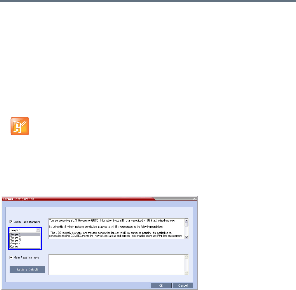
Ultra Secure Mode
Polycom®, Inc. 845
Erase Session History After Logout
In Ultra Secure Mode, the Collaboration Server Web Client and RMX Manager leave no session information
on the user’s workstation or the MCU after the user logs off.
Banner Display and Customization
The Login Screen and Main Screen of the Collaboration Server Web Client and the Collaboration Server
Manager can display informative or warning text banners. These banners can include general information
or they can be cautioning users to the terms and conditions under which they may log into and access the
system, as required in many secured environments.
Banner display is enabled via Setup > Customize Display Settings > Banners Configuration.
The administrator can choose one of four alternative login banners to be displayed. The four alternative
banners cannot be modified. A Custom banner (default) can also be defined.
The Main Page Banner is blank and can be defined.
The Banner Configuration dialog box allows the administrator to select a Login Page Banner from a
drop-down menu.
One of the following Login Page Banners can be selected:
●Non-Modifiable Banners
Sample 1
Sample 2
Sample 3
Sample 4
●Modifiable Banner
Custom (Default)
When the ULTRA_SECURE_MODE system flag is set to YES, the banners are displayed by default
and cannot be disabled. When set to NO (default), banner display is according to the check box
selection in the Banners Configuration dialog box.

Ultra Secure Mode
Polycom®, Inc. 846
Guidelines for Customizing the Login Page Banner
●The Login Page Banner cannot be disabled when the Collaboration Server is in Ultra Secure Mode.
●The Login Page Banner must be acknowledged before the user is permitted to log in to the system.
●If a Custom banner has been created, and the user selects one of the alternative, non-modifiable
banners the Custom banner not deleted.
●The Custom Login Page Banner banner may contain up to 1300 characters.
●An empty Login Page Banner is not allowed.
●Any attempt to modify a non-modifiable banner results in it automatically being copied to the Custom
banner.
Non-Modifiable Banner Text
Sample 1 Banner
You are accessing a U.S. Government (USG) Information System (IS) that is provided
for USG-authorized use only.
By using this IS (which includes any device attached to this IS), you consent to the
following conditions:
− The USG routinely intercepts and monitors communications on this IS for purposes
including, but not limited to, penetration testing, COMSEC monitoring, network
operations and defense, personnel misconduct (PM), law enforcement (LE), and
counterintelligence (CI) investigations.
− At any time, the USG may inspect and seize data stored on this IS.
− Communications using, or data stored on, this IS are not private, are subject to
routine monitoring, interception, and search, and may be disclosed or used for any
USG authorized purpose.
− This IS includes security measures (e.g., authentication and access controls) to
protect USG interests--not for your personal benefit or privacy.
− Notwithstanding the above, using this IS does not constitute consent to PM, LE or
CI investigative searching or monitoring of the content of privileged communications,
or work product, related to personal representation or services by attorneys,
psychotherapists, or clergy, and their assistants. Such communications and work
product are private and confidential. See User Agreement for details.
Sample 2 Banner
This system is for the use of authorized users only. Individuals using this computer
system without authority, or in excess of their authority, are subject to having all
of their activities on this system monitored and recorded by systems personnel. In
the course of monitoring individuals improperly using this system, or in the course
of system maintenance, the activities of authorized users also may be monitored.
Anyone using this system expressly consents to such monitoring and is advised that if
such monitoring reveals possible criminal activity, system personnel may provide the
evidence of such monitoring to law enforcement officials.
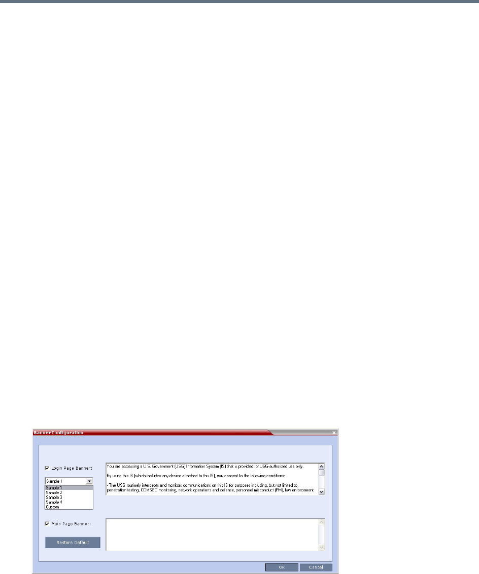
Ultra Secure Mode
Polycom®, Inc. 847
Sample 3 Banner
You are about to access a system that is intended for authorized users only. You
should have no expectation of privacy in your use of this system. Use of this system
constitutes consent to monitoring, retrieval, and disclosure of any information
stored within the system for any purpose including criminal prosecution.
Sample 4 Banner
This computer system including all related equipment, network devices (specifically
including Internet access), is provided only for authorized use. All computer systems
may be monitored for all lawful purposes, including ensuring that their use is
authorized, for management of the system, to facilitate protection against
unauthorized access, and to verify security procedures, survivability and operational
security. Monitoring includes active attacks by authorized personnel and their
entities to test or verify the security of the system. During monitoring, information
may be examined, recorded, copied and used for authorized purposes. All information
including personal information, placed on or sent over this system may be monitored.
Use of this system, authorized or unauthorized, constitutes consent to monitoring of
this system. Unauthorized use may subject you to criminal prosecution. Evidence of
any such unauthorized use collected during monitoring may be used for administrative,
criminal or other adverse action. Use of this system constitutes consent to
monitoring for these purposes.
Customizing Banners
The Login and Main Screen banners can be customized to display conference information, assistance
information or warning text as required in the Ultra Secure Mode.
To customize the banners:
1In the Collaboration Server menu, click Setup > Customize Display Settings > Banners
Configuration.
The Banners Configuration dialog box opens.
Ultra Secure Mode
Polycom®, Inc. 848
2Customize the banners by modifying the following fields:
3Click the OK button.
Banner Configuration
Field
Description
Check Box Text Field
Restore Default
Button
Login Page
Banner Select or clear the
check box to enable
or disable the display
of the banner.
Note: Banner display
cannot be disabled
when ULTRA
SECURE_MODE flag
is set to YES.
Edit the text in this field to meet
local requirements:
•Banner content is multilingual
and uses Unicode, UTF-8
encoding. All text and special
characters can be used.
•Maximum banner size is
100KB.
•The banner may not be blank
when ULTRA SECURE_MODE
flag is set to YES.
Click the button to
restore the default text
to the bannerMain Page
Banner
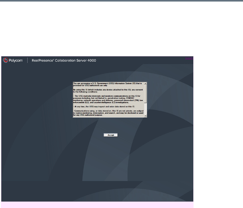
Ultra Secure Mode
Polycom®, Inc. 849
Banner Display
Login Screen Banner
The Login screen banner can display any text, for example the terms and conditions for system usage. The
default text is that required in Ultra Secure Mode. The user must acknowledge that the information was read
and click the Accept button to proceed to the Login screen as shown in the following screen:
When the Collaboration Server is configured to work in Ultra Secure Mode, such as Maximum Security
Environments, the display banner includes the terms and conditions for system usage as detailed in the
default text: contained in Sample Banner 1.
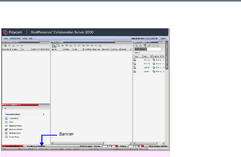
Ultra Secure Mode
Polycom®, Inc. 850
Main Screen Banner
The Main Screen banner is displayed at the bottom of the screen, as follows:
When the Collaboration Server is configured to work in Ultra Secure Mode, such as the Maximum Security
environment, the display banner includes the following default text:
THIS IS A DOD SYSTEM AND IS SUBJECT TO MONITORING, UNAUTHORIZED USE MAY SUBJECT YOU
TO ADMINISTRATIVE ACTION OR CRIMINAL PROSECUTION AND PENALTIES.
Securing an External Database
TLS 1.0 is used when securing communications between the Collaboration Server and an external
database. The certificate is installed on the database server and the Collaboration Server is the client. When
the certificate is installed on the database server, all client requests and responses are transferred via
secure port 443.
It is important to verify that the external database application is operating in secure mode before enabling
secure external database communications on the Collaboration Server. The Collaboration Server checks
the validity of external database’s certificate before communicating. If there is a certificate error an Active
Alarm is raised with Error in external database certificate in the description field.
To enable secure Collaboration Server Communications with an External Database:
●Set the Collaboration Server to communicate with the database server via port 443 by setting the
value of the System Flag EXTERNAL_DB_PORT in system.cfg to 443.
For more information see Modifying System Flags.
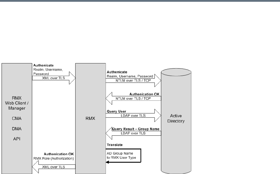
Ultra Secure Mode
Polycom®, Inc. 851
MS Active Directory Integration
It is possible to configure direct interaction between the Collaboration Server and Microsoft Active Directory
for Authentication and Authorization of Management Network users.
The following diagram shows a typical user authentication sequence between a User, Collaboration Server
and Active Directory.
Directory and Database Options
Ultra Secure Mode
Internal Collaboration Server database and Active Directory
Authentication is first attempted using the internal Collaboration Server database. If it is not successful
authentication is attempted using the Active Directory.
Standard Security Mode
Internal Collaboration Server database + External Database
First authentication is via the internal Collaboration Server database. If it is not successful, authentication is
via the External Database.
Internal Collaboration Server database + External Database + Active Directory
●Management Logins
First authentication is via the internal Collaboration Server database. If it is not successful,
authentication is via the Active Directory.
●Conference Queries (Chairperson Password, Numerical ID etc.)
First authentication is via the internal Collaboration Server database. If it is not successful,
authentication is via the External Database.

Ultra Secure Mode
Polycom®, Inc. 852
Guidelines
●The Collaboration Server maintains a local record of:
Audit Events – users that generate these events are marked as being either internal or external.
Successful user logins
Failed user login attempts
●User passwords and user lockout policy for external users are managed via Active Directory’s
integration with the user’s host machine.
●Enabling or disabling Active Directory integration does not require a reset.
●In Standard Security Mode multiple accounts of all user types are supported. In Ultra Secure Mode,
enabling Active Directory integration is only permitted if the Collaboration Server only has one local
Administrator User.
●Multiple Machine Accounts with various roles are supported.
●Microsoft Active Directory is the only directory service supported.
●Active Directory integration is configured as part of the Management Network.
●Both IPv4 and IPv6 addressing are supported.
●In Standard Security Mode, the Active Directory can be queried using NTLM with or without TLS
encryption. In Ultra Secure Mode, TLS encryption is required.
●Server and client certificate validation requests use LDAP with or without TLS encryption.
•When using LDAP over TLS, in addition to using port 389 with STARTTLS, the administrator has
the option of using port 636.
•LDAP is not supported by Collaboration Server (RMX) 1800-0.
•The Active Directory setting define Send NTLMv2 response only. Refuse LM & NTLM (in the
group policy management > forest > polycomdemo.com > group policy objects > default
domain policy > edit > computer configuration > policies > windows settings > security
settings > local policies > security options > network security: Lan Manager authentication
level) is not supported with the Collaboration Server.
•Active Directory is not supported by Collaboration Server (RMX) 1800-0.
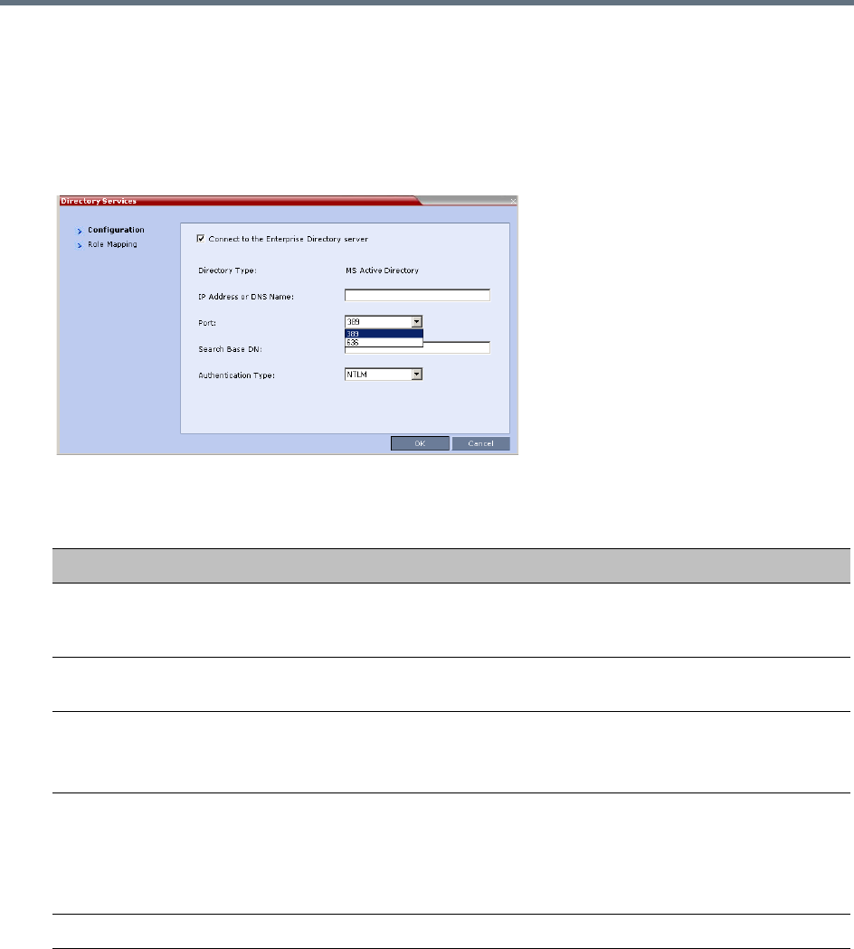
Ultra Secure Mode
Polycom®, Inc. 853
Enabling Active Directory Integration
To configure Directory Services:
1On the Collaboration Server Menu, click Setup > Directory Services.
The Directory Services - Configuration dialog box is displayed.
2Modify the following fields.
Directory Services - Configuration
Field Description
Connect to the
Enterprise Directory
Server
Select this check box to enable or disable the Active Directory feature.
IP Address or DNS
Name
Enter the IP address or DNS name of the Enterprise Directory Server (Active
Directory).
Port Select the Port according to the Authentication Protocol to be used:
•389 - NTLM over TCP
•636 - NTLM over TLS
Search Base DN Enter the starting point when searching for User and Group information in the
Active Directory.
For example if the Domain Name is: mainoffice.bigcorp.com.uk
The entry in this field should be:
CN=Users,DC=mainoffice,DC=bigcorp,DC=come,DC=uk
Authentication Type Only NTLM can be used.
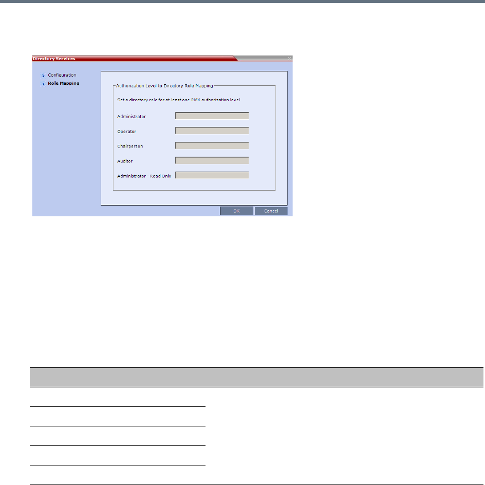
Ultra Secure Mode
Polycom®, Inc. 854
3Click the Role Mapping tab.
The Directory Services - Role Mapping dialog box is displayed.
Each of the Collaboration Server user types: Administrator, Administrator Read-Only, Auditor,
Operator and Chairperson can be mapped to only one Active Directory Group or Role according
to the customer’s specific implementation.
In Ultra Secure Mode there are only two user types: Operator and Administrator.
A Collaboration Server user that belongs to multiple Active Directory Groups is assigned to the
Group with the least privileges.
4Map the Collaboration Server User Types, to their Active Directory roles by modifying the following
fields.
5Click OK.
Restoring the Collaboration Server Using the USB Port
When the RMX is in Ultra Secure Mode, restoring the RealPresence® Collaboration Server
1500/2000/4000 using the USB port can be used to set the RMX back to its factory default settings, if for
any combination of factors the system becomes unstable or unmanageable.
For a full description of this procedure see Restoring the RMX Using the USB Port in the RealPresence®
Collaboration Server (RMX®) 1500/2000/4000 Deployment Guide for Maximum Security Environments.
Directory Services - Role Mapping
Field Description
Administrator At least one of these User Types must be mapped to an Active
Directory Role.
Administrator Read-Only
Operator
Chairperson
Auditor

Ultra Secure Mode
Polycom®, Inc. 855
MLPP (Multi Level Precedence and Preemption)
In compliance with UC APL requirements, Quality of Service (QoS) can be more accurately modified to suit
local needs with the addition of Multi Level Precedence and Preemption methods for call prioritizing and call
handling.
QoS is important when transmitting high bandwidth audio and video information. QoS can be measured and
guaranteed in terms of:
●Latency
●Low packet throughput
●Average delay between packets
●Jitter (variation in delay)
●Transmission error rate
●Order of packet delivery
Precedence is the method by which a call is assigned a priority level. The RMX supports two separately
defined and configurable Domains, each having its own Precedence policy.
For a full description of Precedence see IETF RFC 2474.
One of the following Precedence Levels is assigned to all calls:
Conferences can have a mix of participants from different Precedence domains and network domains.
Precedence is supported for both IPv4 and IPv6.
Preemption is the method whereby, when system resources are insufficient, lower priority calls are
terminated and their resources assigned to higher priority calls. Preemption is typically a function of network
components such as the Local Session Controller (LSC). To the RMX, a preempted call appears as a
disconnected call.
Precedence Levels
Highest Priority FLASH-OVERRIDE-OVERRIDE (Classified Networks only)
FLASH-OVERRIDE
FLASH
IMMEDIATE
PRIORITY
Lowest Priority ROUTINE
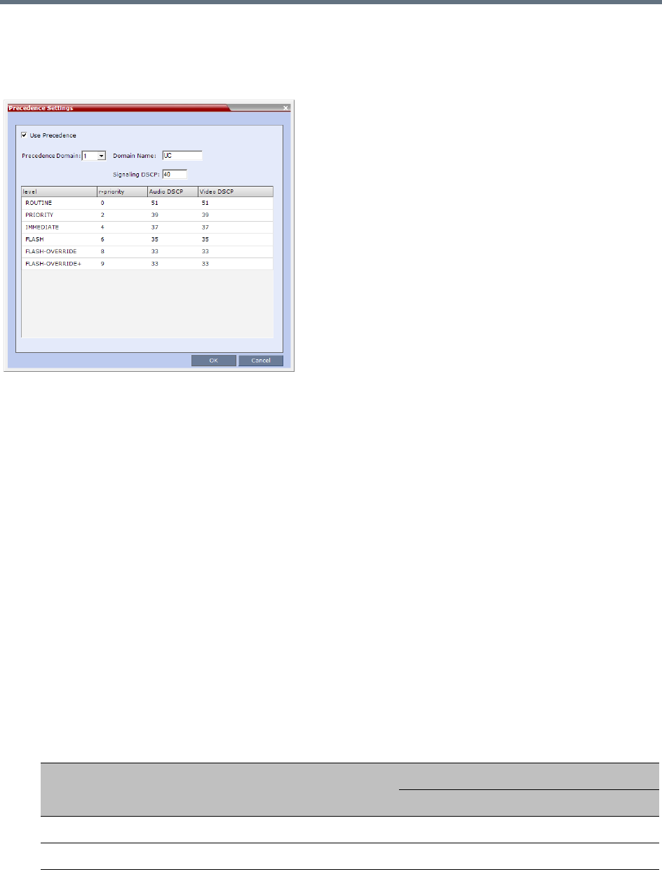
Ultra Secure Mode
Polycom®, Inc. 856
Enabling Precedence
Precedence is disabled by default. It is enabled by using the Setup > Precedence Settings menu to display
the Precedence Settings dialog box. Precedence is enabled by selecting the Use Precedence check box.
See Configuring and Modifying Precedence Domains and DSCP Values.
When Precedence is enabled, all other QoS system settings are overridden by the parameters sent in the
SIP Message. For more information about QoS, see Modifying the Default IP Network Service.
SIP Message
A SIP Message is a request or a response between network entities that communicate using the SIP
protocol. The SIP Message header contains Precedence and Resource Priority (r-value) information and an
optional Require tag for each call.
For a full description of SIP Messages see IETF RFC 3261.
For a full description of Resource Priority (DSCP) see IETF RFC 2474.
For a full description of SIP r-priority see IETF RFC 4412.
Dial-in calls
If the Use Precedence check box in Precedence Settings is selected:
●The RMX uses the information in the SIP Message header to match the call to a Precedence Domain
and a Precedence Level. The table below summarizes the default values.
Precedence Domain and Resource Priority - DSCP Default Values
Resource
Priority Precedence Level
DSCP Value
Audio Video
9 FLASH-OVERRIDE-OVERRIDE 33 (0x21) 33 (0x21)
8 FLASH-OVERRIDE 33 (0x21) 33 (0x21)
Ultra Secure Mode
Polycom®, Inc. 857
●SIP Dial in participants, both defined and undefined, do not inherit Precedence or Domain
characteristics from the Participant’s Address Book. (Additional fields, added to the Participant’s
Properties - Advanced and Address Book - Advanced dialog boxes are used to enter and modify
Precedence or Domain characteristics for SIP Dial-out participants.)
●For backward compatibility, calls received with a SIP Message header that contains no Precedence
Domain and the Resource Priority information, are assigned ROUTINE priority in the first defined
Precedence Domain.
●Incoming calls are accepted or rejected depending on the:
Value of the REJECT_INCORRECT_PRECEDENCE_DOMAIN_NAME System Flag.
Match or mismatch of the Precedence Domains, set in the RMX and contained in the incoming
SIP Message r-value.
The r-value is of the following format:
r-value = <domain name>-<subdomain>.<r-priority>
The table below shows an example of calls accepted or rejected assuming:
Domain Name = UC
Sub Domain = 000000
r-priority = 2
6 FLASH 35 (0x23) 35 (0x23)
4 IMMEDIATE 37 (0x25) 37 (0x25)
2 PRIORITY 39 (0x27) 39 (0x27)
0 ROUTINE 51 (0x33) 51 (0x33)
NONE No Resource Priority header for backward compatibility
Precedence Domain and Resource Priority - DSCP Default Values
Resource
Priority Precedence Level
DSCP Value
Audio Video
Ultra Secure Mode
Polycom®, Inc. 858
●Rejected calls receive a 417 Error response.
●If the Require tag is null, the call is connected and assigned ROUTINE priority in the first defined
Precedence Domain
●If the Use Precedence check box in Precedence Settings is cleared, the RMX will not reject such
calls. The LSC is responsible for rejecting such calls.
Example - Call Acceptance by System Flag Value and Precedence Domain Matching
Call Acceptance
Precedence Domain
Flag Value:
REJECT_INCORRECT_PRECEDENCE_DOMAIN_NAME
RMX
Incoming SIP
Message YES NO (Default)
UC UC
Call Accepted
Call Accepted
and
assigned ROUTINE priority
UC UC.00001
UC UC.00002
UC-00000 UC-00000
UC-00000 UC-00001
UC-00000 UC
UC UC00002
Call RejectedUC UCC
UCC UC
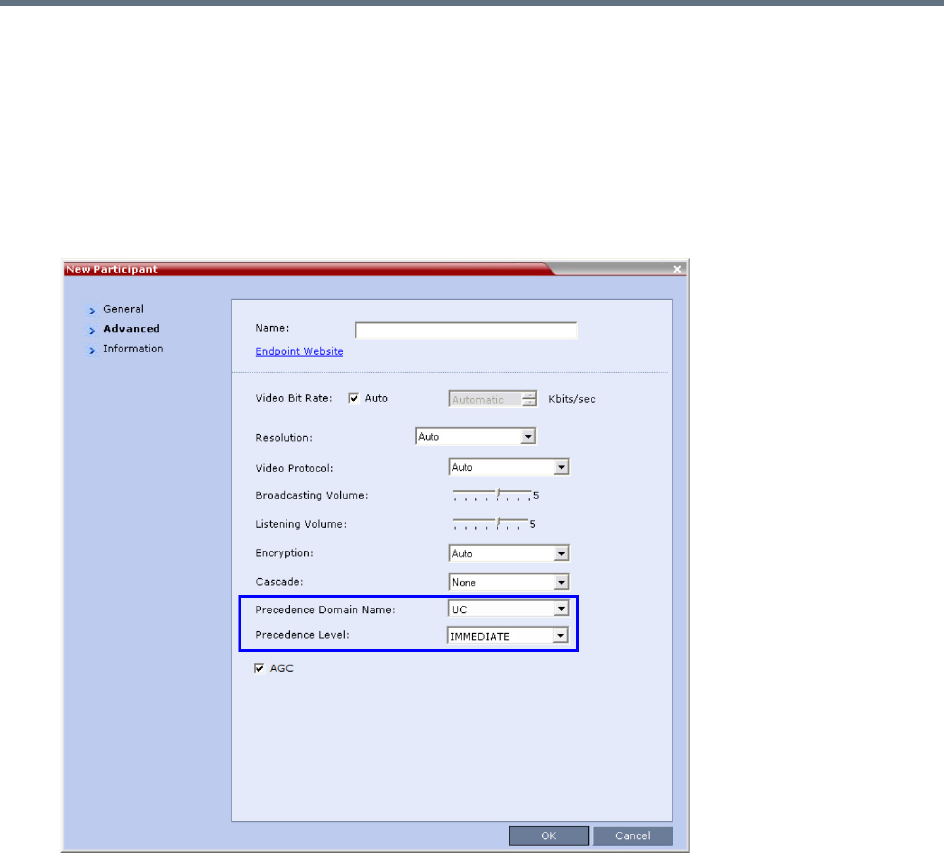
Ultra Secure Mode
Polycom®, Inc. 859
Dial-out calls
For Dial-out calls, the SIP Message header information for the Precedence Domain and Resource Priority
(r-priority) of the call is configurable.
Additional fields in the Participant’s Properties - Advanced and Participant’s Address Book - Advanced
dialog box are used to modify these parameters:
●Precedence Domain Name
●Precedence level
Precedence Level Change
The Precedence Level of all calls can only be changed by the LSC sending a Re-Invite or similar SIP
Message to the Collaboration Server.
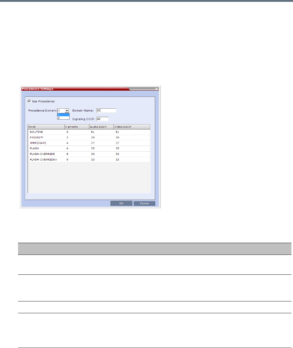
Ultra Secure Mode
Polycom®, Inc. 860
Configuring and Modifying Precedence Domains and DSCP Values
The Precedence Domains and DSCP values for each Precedence Domain can be configured and modified
per MCU.
To configure Precedence Settings:
1On the RMX menu, click Setup > Precedence Settings
The Precedence Settings dialog box is displayed.
2 Optional: Modify the values if required.
Precedence Settings - Domains, Levels and DSCP Values
Field Description
Use Precedence Select or clear the check box to enable or disable Precedence.
Default: Cleared (Precedence disabled)
Precedence Domain Select the Precedence Domain to be modified, 1 or 2, from the drop-down
menu.
Possible Values: 1 / 2
Domain Name Enter the required Domain Name.
Signaling DSCP Modify the DSCP value of the Signaling DSCP. A single Signaling Proxy is used
for all Precedence Levels.
Default: 40
Range: 0 - 63
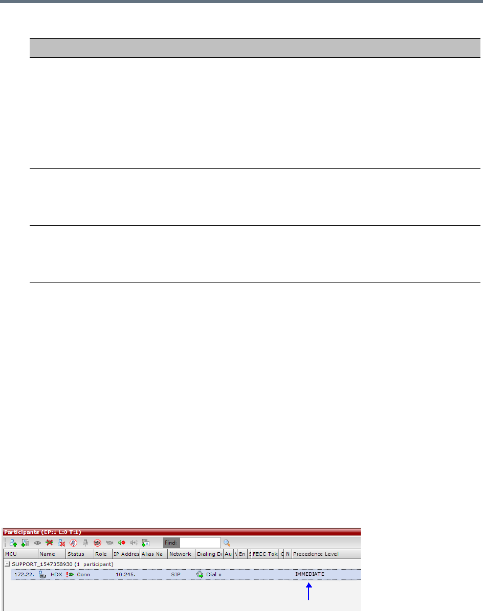
Ultra Secure Mode
Polycom®, Inc. 861
3Click OK.
System Flags
The following System Flags must be added to system.cfg if their values are to be modified:
●QOS_MANAGEMENT_NETWORK - the overall hex value of the DiffServ field (not just the value of
the DSCP portion) is used as the DSCP value for the RMX Management Network.
Default: 0x10
Range: 0x00 - 0xFC
●REJECT_INCORRECT_PRECEDENCE_DOMAIN_NAME - see Dial-in calls (above) for a
description of this flag.
Default: NO
Range: YES / NO
Monitoring Precedence Level
The Precedence Level of each connected participant is listed in the Participants list pane.
Level r-priority, Audio DSCP and Video DSCP values can be modified for each of the
six Precedence Levels:
•ROUTINE
•PRIORITY
•IMMEDIATE
•FLASH
•FLASH-OVERRIDE
•FLASH-OVERRIDE+
r-priority Modify the r-priority value for the Level.
Range: 0 - 255.
Default: ROUTINE - 0, PRIORITY - 2, IMMEDIATE - 4, FLASH - 6,
FLASH-OVERRIDE - 8, FLASH-OVERRIDE+ - 9
Audio/Video DSCP Modify the DSCP value for the Audio/Video DSCP.
Range: 0 - 63.
Default: ROUTINE - 51, PRIORITY - 39, IMMEDIATE - 37, FLASH - 35,
FLASH-OVERRIDE - 33, FLASH-OVERRIDE+ - 31
Precedence Settings - Domains, Levels and DSCP Values
Field Description

Ultra Secure Mode
Polycom®, Inc. 862
IEEE 802.1X Authentication
In compliance with UC APL requirements for enhanced security of wireless local area networks that follow
the IEEE 802.11 standard, support for 802.1X Authentication has been included in this version.
802.1X Authentication requires that the RMX registers with a 802.1X Authentication Server and is supported
on RMX 1500/2000/4000 The authentication protocol is applied to each the following Network Interface
Controllers (NICs):
●Management
●Signaling
●Media
The following 802.1X Authentication methods are supported:
●EAP-MD5
●EAP-TLS
●PEAPv0
●MSCHAPv2
Certificate Repository
Implementation of 802.1X Authentication requires a certificate, which is obtained from the Certificate
Repository.
●Either one TLS certificate is retrieved for all IP services and their associated NICs,
If one certificate is retrieved for all NICs, the RMX will use the Management Certificate for all the
NICs.
or
● A TLS certificate for each IP service and their associated NICs is retrieved from the Certificate
Repository:
If several different TLS certificates are retrieved, each NIC will use the certificate of the service
that it is associated with.
In a system configured with Multiple Network Services each IP service will use its own
certificate.
A NIC that does not have its own certificate will first attempt to use the Management Certificate
before using a self-signed certificate.
For RMX 2000, Network Separation must be implemented before configuring 802.1X Authentication.
802.1X Authentication is not supported in Microsoft environments.
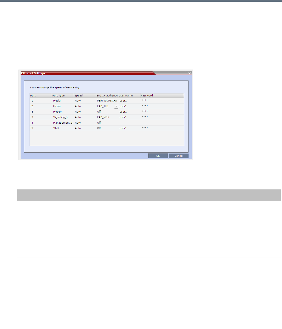
Ultra Secure Mode
Polycom®, Inc. 863
Enabling and Configuring 802.1X Authentication
802.1X Authentication for each NIC is enabled or disabled in the Setup > Ethernet Settings dialog box.
The following additional table columns are used to modify these parameters:
●802.1X Authentication
●User Name
●Password
Modify the Ethernet Settings table fields as set out below:
802.1X Authentication - Configuration
Field Description
802.1x Authentication For each NIC, click the arrow to open the drop-down menu and select (or
disable) the 802.1X Authentication method:
•Off
•EAP-MD5
•EAP-TLS
•PEAPv0
•MSCHAPv2
User Name Enter the User name that the RMX will use to register with the 802.1X
Authentication Server. This must be the RMX’s DNS name and can be up to
256 characters.
Note: If the Domain Name (DC) field was completed in the Certificate Request,
the User must be: <Common Name (DNS)>@<Domain Name (DC)> as set
out in the Certificate Request.
Password
(EAP-MD5, PEAPv0 and
MSCHAPv2 only)
Enter the Password, that the RMX will use to register with the 802.1X
Authentication Server. Up to 256 Unicode characters can be used.
The Password is always displayed as four asterisks.
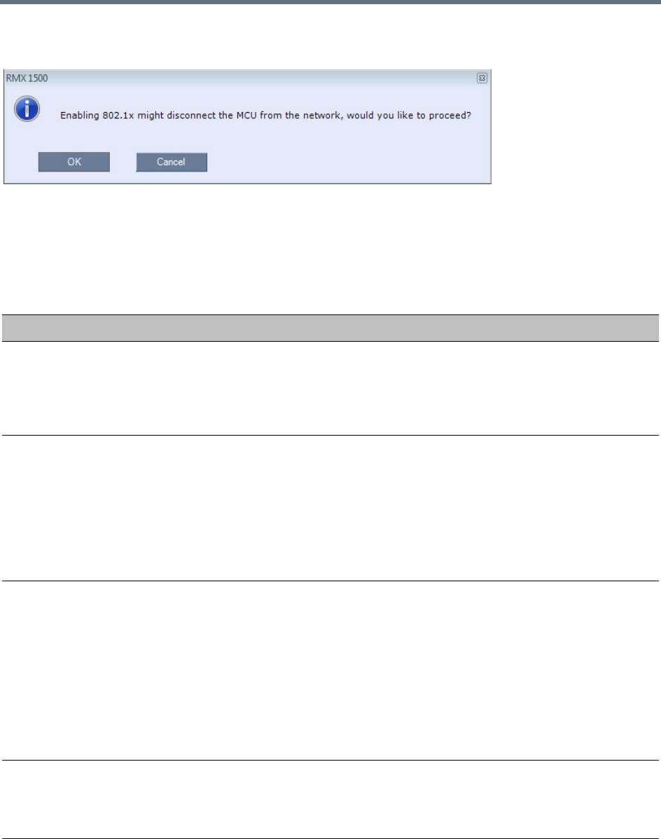
Ultra Secure Mode
Polycom®, Inc. 864
Enabling 802.1X Authentication can result in the RMX being disconnected from the network and a warning
message is displayed:
System Flags
The following system flags are used to manage the 802.1X Authentication process. They must be manually
added to system.cfg if their default values need to be modified.
802.1X Authentication System Flags
Flag name Description
802_1X_CERTIFICATE_MODE Determines whether one TLS certificate is retrieved from the
Certificate Repository for all IP services or if multiple certificates will be
retrieved, one for each IP service.
Range: ONE_CERTIFICATE, MULTIPLE_CERTIFICATE
Default: ONE_CERTIFICATE.
802_1X_SKIP_CERTIFICATE_VALIDATI
ON
If the flag value is:
•YES - The retrieved certificate is not validated against the CA
certificate.
•NO - The retrieved certificate is validated against the CA certificate.
Validation failure raises an Active Alarm and is reported in the
Ethernet Monitoring dialog box.
Range: YES, NO.
Default: YES.
802_1X_CRL_MODE If the flag value is:
• ENABLED - Forces CRL checking. The system fails the connection
request if the certificate has been revoked or if there is no CRL.
• OPTIONAL - The system fails the connection request if the
certificate is revoked but does not fail the connection request if there
is no CRL.
•DISABLED - Does not check the CRL and does not fail the
connection request based on the CRL content.
Range: ENABLED, OPTIONAL, DISABLED
Default: DISABLED.
802_FIPS_MODE If the flag value is YES, the availability of the MD5 Authentication
Protocol will neither be displayed as selectable option nor supported.
Range: YES/NO.
Default: NO
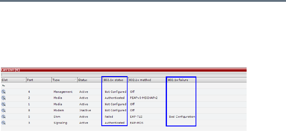
Ultra Secure Mode
Polycom®, Inc. 865
Disabling 802.1X Authentication
Switching to http mode from https mode by inserting a USB key containing a file named
RestoreFactorySecurityDefaults.txt into the RTM-IP USB port disables 802.1X functionality
Ethernet Monitoring
802.1x Status is displayed in the Hardware Monitor - LAN List.
The following 802.1X Statuses are possible:
●Authenticated
●Not Configured
●Failed
The following 802.1X Failure reasons are possible:
●Bad Configuration
●Link Status not Detected
White List Access
In compliance with UC APL requirements for enhanced security of web access to the RMX, a White List
containing the addresses of IP Networking Entities permitted to connect to the RMX’s Management Network
is implemented - Networking Entities such as Network Hosts, Control Workstations, Gatekeepers SIP/ DNS
Servers, etc.
Guidelines
●Only administrators can access and modify the White List.
●During First Time Installation and Configuration, when enabling the White List, the IP address of the
workstation used to run the RMX Web Client is automatically added to the White List.
●The last White List entry cannot be deleted to prevent lock out. Any attempt to enable an empty White
List results in the display of an error message: WhiteList is empty please add IP’s to the list if you
want to enable WhiteList.
●Both IPv4 and IPv6 are supported.
●Web access to the RMX for http and https is through ports 80 and 443 respectively.
●The White List can hold up to 100 entries. An error message is displayed when exceeding this limit.
●Access is blocked at the firewall for devices with IP addresses not listed in the White List.
●The White List is saved during Backup, Restore and Upgrade processes.
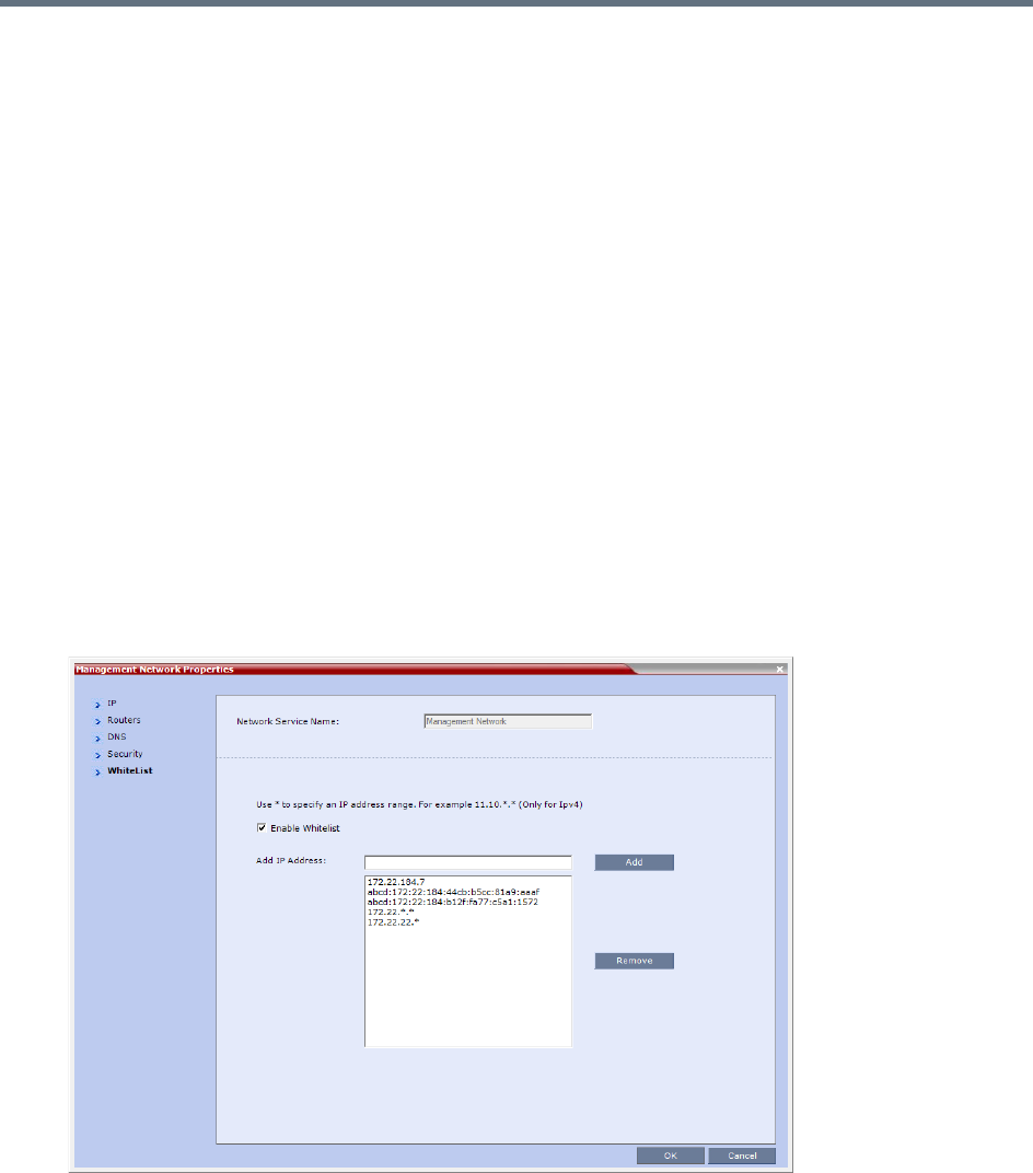
Ultra Secure Mode
Polycom®, Inc. 866
●Changes to the White List are written to the Auditor Event File.
●Alterations to the White List do not require a system reset.
Enabling, Disabling and Modifying the White List
The use of White List in the environment can be enabled or disabled in the Management Network Service
- White List dialog box.
To enable, disable, view or modify the White List:
1In the RMX Management pane, click the IP Network Services.
The IP Network Services pane is displayed.
2In the IP Network Services list pane, double-click the Management Network entry.
The Management Network dialog box is displayed.
3Click the WhiteList tab.
The WhiteList dialog box is displayed.
If there are no entries in the White List, it is disabled to prevent lock out.
If the White List is disabled none of the IP addresses in the list are displayed.
The Add and Remove buttons are only active if the Enable Whitelist check box is selected.
4Select the Enable Whitelist check box.
All IP addresses in the list are displayed and the Add and Remove buttons become active.
5Modify the White List.
Both IPv4 and IPv6 addresses are supported and the system will only allow an entry of the type of
IP addresses for which the Management Network Service is configured according to the table
below.
Ultra Secure Mode
Polycom®, Inc. 867
If the system changes its IP addressing mode (e.g. from IPv4 only to both IPv4 &6) while the
White List is enabled, the White List is disabled and a message, White list has been disabled
please reconfigure, is displayed.
IPv4 addresses can be added as a range by using the wildcard character, *, to substitute the 3rd
and 4th dotted decimal numbers of the IP address, e.g. 11.10.*.*
aTo Add IP addresses:
For each IP address to be added to the White List:
iIn the Add IP Address field enter an IP address to be added to the White List and click the
Add button.
If an invalid IP address is entered, an error message is displayed and the administrator is
prompted to enter a correct IP address.
If a duplicate IP address is entered, a message: Duplicate IP’s are not allowed in WhiteList
is displayed.
ii When all the IP addresses have been added, click OK.
A message is displayed: Applying white list will limit RMX web access to the configured
IP list, are you sure you want to continue?
iii Click Yes to apply the modified White List.
bTo Remove IP addresses:
For each IP address to be removed from the White List:
iIn the White List, click to select an IP address to be removed from the White List.
Click the Remove button.
ii When all the IP necessary addresses have been removed, click OK.
A message is displayed: Applying white list will limit RMX web access to the configured
IP list, are you sure you want to continue?
iii Click Yes to apply the modified White List.
IP Address Modes
IP Address Modes
RMX Workstation / Device
IPv4
IPv4
IPv4 & IPv6
IPv6
IPv6
IPv4 & IPv6
IPv4 & IPv6
IPv4
IPv6
IPv4 & IPv6

Ultra Secure Mode
Polycom®, Inc. 868
Alternative Network Address Types (ANAT)
In compliance with UC_APL_NET_0007 Alternative Network Address Types (ANAT) is supported.
When the RMX is configured for IPv4 and IPv6 Addressing, the addition of the sdp-anat option tag in the
SIP Require and SIP Supported headers allows a mixture of IPv4 and IPv6 addressing to be specified by
the Session Description Protocol (SDP).
For a full description of ANAT see IETF RFCs 4091 and 4092.
Guidelines
●BFCP over TCP is not supported in Ultra Secure Mode. It’s associated Content channel is not
available.
●BFCP over UDP is supported in Ultra Secure Mode.
●If the RMX is configured for both IPv4 and IPv6, IPv4 addressing is given preference when
establishing the connection.
●If an Outbound Proxy is configured, its transport type is used.
●If an Outbound Proxy is not configured, the SIP Server’s (Registrar) transport type is used.
The Outbound Proxy and the SIP Server must be configured with one type only either according to
the IP address type or according to the DNS Resolution type. However, if the RMX is configured for
IPv4&IPv6 then the SIP Contact field will contain both IPv4 and IPv6 addresses.
System Flag
The ANAT Protocol selection is controlled by the ANAT_IP_PROTOCOL System Flag.
To modify it, manually add it to system.cfg and set its value as described in the table below.
Range: DISABLED, AUTO, PREFER_IPv4, PREFER_IPv6
Default:
If the ULTRA_SECURE_MODE System Flag is set to NO: DISABLED.
If the ULTRA_SECURE_MODE System Flag is set to YES: AUTO.
ANAT_IP_PROTOCOL System Flag Values for Dial in Dial out
Value Behavior - Dial in and Dial out
DISABLED sdp-anat does not appear in SIP headers and the SDP does not contain a mixture of
IPv4 and IPv6.
If an endpoint requests ANAT (sends the Require: sdp-anat tag) the RMX will accept
the call.
AUTO sdp-anat appears in SIP headers.
Dial in: The IP Version preference is according to the SDP priority.
Dial out: IPv4 is advertised first.
PREFER_IPv4 sdp-anat appears in SIP headers.
Dial in: IPv4 is the IP Version preference.
Dial out: IPv4 is advertised first.
Ultra Secure Mode
Polycom®, Inc. 869
BFCP Over UDP – AS-SIP Content
In compliance with UCR 2008 Change 3, AS-SIP (Assured Services-Session Initiation Protocol) Content
flow is an implementation of SIP that utilizes SIP’s built in security features.
When using AS-SIP Content, the media line of the content channel is not sent as part of the initial SDP
Offer/Answer message sequence. The media line of the Content channel is only sent to the MCU when an
endpoint wanting to share Content initiates Content sharing. The Collaboration Server (RMX) then sends
the Content media line to all conference participants using an SDP Re-invite.
Guidelines
●AS-SIP Content is shared using Multiple Resolutions (Content Transcoding) and is not supported in
any other Content sharing mode such as H.263 Content and H.264 Cascade Optimized Content
Protocol.
●Multiple Resolutions consumes system video resources. If sufficient system video resources are not
available, a conference with AS-SIP Content enabled in its Profile, will not be created. An error:
Conference could not be created due to lack of Content DSP resources, is displayed.
●The SIP BFCP UDP application line is included in SDP Offer/Answer message sequence.
●An endpoint declaring SIP BFCP TCP is connected with video and audio but without Content. The
SIP BFCP TCP channel will not be connected.
●The following resolutions are supported with H.264 HD Content protocol. Only when H.264 HD is
selected, these resolutions are enabled for selection:
HD 720p5
HD 720p30
HD 1080p15
●Endpoints that do not support receiving H.264 Content at a resolution of HD 720p5 or greater are
considered Legacy Endpoints and will receive Content using the people video channel.
●Endpoints that do not support transmitting H.264 Content at a resolution of HD 720p5 or greater are
considered Legacy Endpoints and will transmit Content using the people video channel. Depending
on the endpoint type, these endpoints may not be able to transmit Content at all - this is dependent
on the endpoint and is not controlled by the RMX.
●A mixture of older, non AS-SIP compliant and AS-SIP compliant endpoints are supported in the same
conference and are able to share Content.
●An endpoint connecting during a Content session is immediately sent an SDP Re-invite that includes
the connect media line and will receive Content.
●An endpoint connecting after Content started and was stopped will receive the SDP Re-invite and the
content media line only after a new Content request is sent.
PREFER_IPv6 sdp-anat appears in SIP headers.
Dial in: IPv6 is the IP Version preference
Dial out: IPv6 is advertised first.
ANAT_IP_PROTOCOL System Flag Values for Dial in Dial out
Value Behavior - Dial in and Dial out
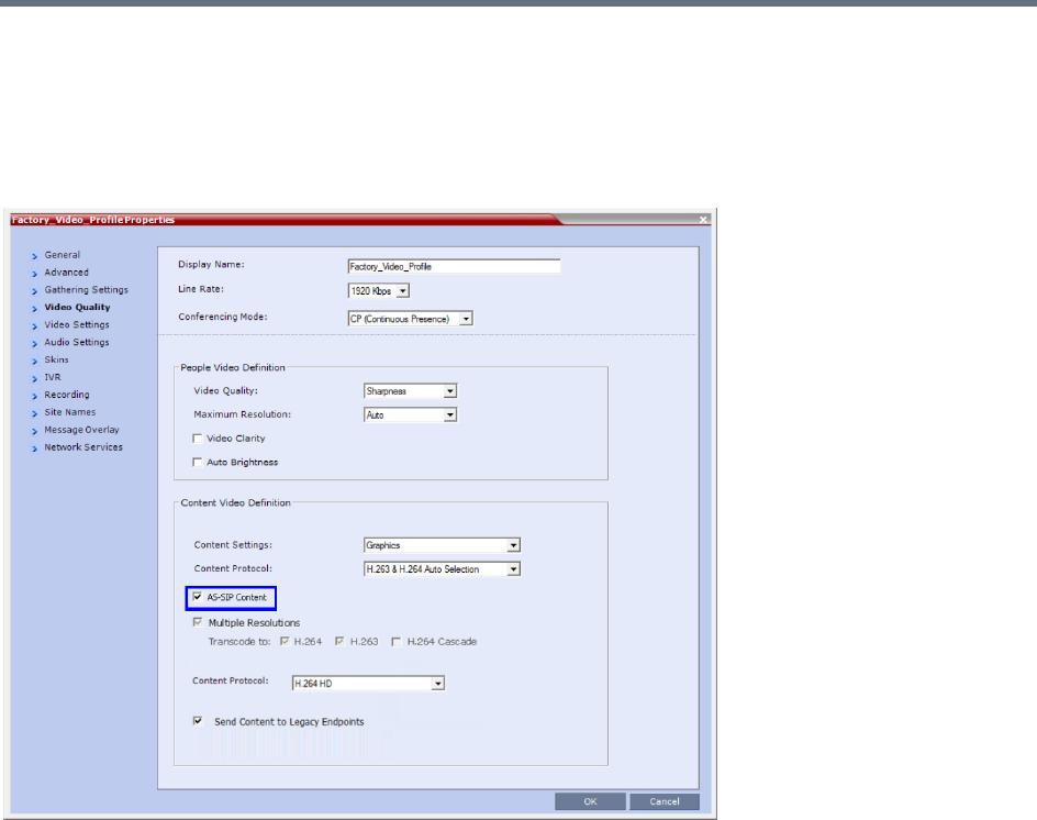
Ultra Secure Mode
Polycom®, Inc. 870
●Once Content has been initiated by one of the endpoints, the Content channel will be opened to all
endpoints and remain open even if the Content sharing endpoint stops sharing Content.
Enabling AS-SIP Content
AS-SIP Content is enabled in the New Profile / Profile Properties - Video Quality tab.
When the AS-SIP Content check box is selected the following are automatically enabled and cannot be
disabled:
●Send Content to Legacy Endpoints
●Multiple Resolutions
System Flag
The time that the RMX waits for endpoints to respond to its SDP Re-invite is determined by a timer. The
timer duration, in seconds, is controlled by the AS_SIP_CONTENT_TIMER System Flag. Its default value
is 10 seconds. To modify the timer value, manually add this flag to system.cfg and modifying its value as
required:
Range: 1 - 60 seconds. (Values outside this range are rejected and an error message is displayed.)

Ultra Secure Mode
Polycom®, Inc. 871
Internet Control Message Protocol (ICMP)
ICMP (Internet Control Message Protocol) is used to send messages between networked entities. It is
typically used to send and receive information concerning:
●Communications errors in network applications
●Remote host reachability and availability
●Network congestion (latency)
●Traffic redirection
Malicious devices can however use these capabilities in order to divert, intercept, detect, network traffic.
The following System Flags have been added to enable the administrator to control ICMP Redirect and
Destination Unreachable messages:
●ENABLE_ACCEPTING_ICMP_REDIRECT
●ENABLE_SENDING_ICMP_DESTINATION_UNREACHABLE
By setting the value of these flags to NO the risk of malicious behavior can be mitigated.
For a full description of ICMP see RFC 792.
Guidelines
●Both flags apply to all MCU platforms: RealPresence Collaboration Server (RMX) 1500/2000/4000/
1800).
●Both flags apply to all Ethernet connections: Management, Signaling, Media, Modem, etc.
System Flag: ENABLE_ACCEPTING_ICMP_REDIRECT
This System Flag enables the administrator to control whether the RMX accepts or rejects ICMP Redirect
Messages (ICMP message type #5), typically used to instruct routers to redirect network traffic through
alternate network elements.
●Range: YES / NO
●Default:
Ultra Secure Mode: NO - Redirect messages or ignored.
Default Security Mode: YES - Redirect messages are accepted.
System Flag: ENABLE_SENDING_ICMP_DESTINATION_UNREACHABLE
This System Flag enables the administrator to control whether the RMX sends ICMP Destination
Unreachable Messages (ICMP message type #3).
Destination Unreachable Messages are sent when the RMX receives a UDP packet on a port configured
for TCP, or receives a UDP packet on a port configured for TCP, or when, in real time, a packet is not
processed in the prescribed time interval. The prescribed time interval is determined by the comparison of
timestamps. The timestamp is a 32-bit field, representing milliseconds since midnight UT. For detailed
timestamp information see RFC 792.
The Destination Unreachable Message may also be sent when Network or Host is unreachable (sent by the
router) or the Port is unreachable (sent by the RMX).
●Range: YES / NO
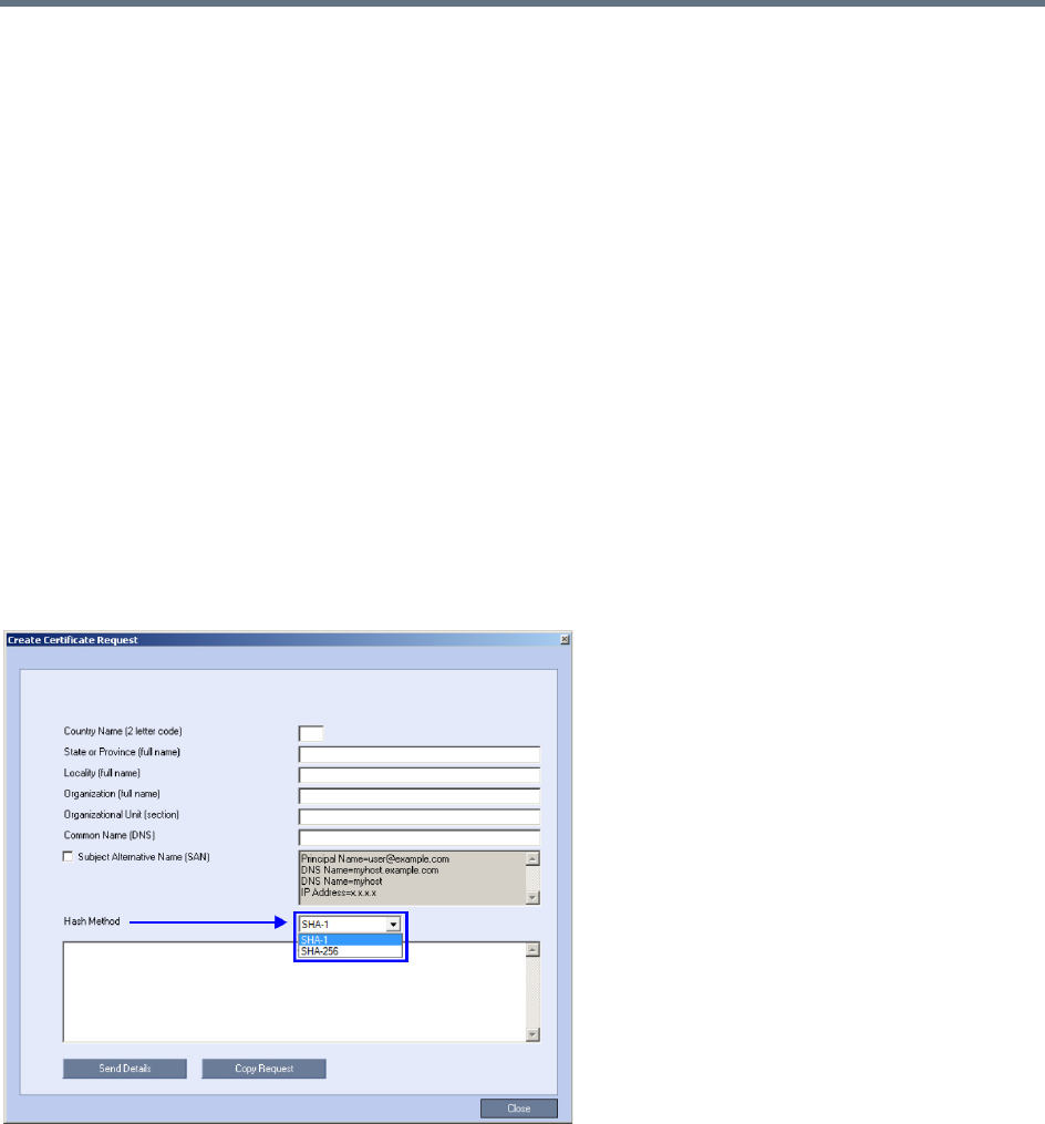
Ultra Secure Mode
Polycom®, Inc. 872
●Default:
Ultra Secure Mode: NO - Destination Unreachable Message is never sent.
Default Security Mode: YES - Destination Unreachable Message is sent when needed.
Modifying the flag values
To modify the System Flags values, the flags must first be manually added to system.cfg.
For more information about System Flags, see .
Password Encryption
In compliance with UC APL, FIPS 140-2 the SHA-256 (Secure Hash Algorithm) is applied to:
●Application login passwords.
●Linux operating system passwords.
●CSRs (Certificate Signing Requests).
The output value for SHA-256 is 256 bits whereas for SHA-1 the output value is 160 bits.
For backward compatibility with previous versions, either SHA-1 or SHA-256 can be selected as the hash
algorithm used in the creation of CSRs.
Upgrade / Downgrade Guidelines
The RMX configuration, including users and passwords, should be backed up before upgrading or
downgrading.
The table below summarizes the system behavior with regard to passwords and certificates when upgrading
to or downgrading from this version.

Ultra Secure Mode
Polycom®, Inc. 873
Version Change - Password and Certificate Compatibility
Version
Change
Behavior
Passwords Certificates
Upgrade
from old version
to new version
On user login:
•All new-user passwords are hashed and
saved using SHA-256.
• Existing user passwords remain saved using
the SHA-1 signature, however:
On first login after the upgrade the SHA-1
hashed password is automatically replaced
with SHA-256 hashed password.
Note: After an upgrade to version 8.1.4.J there
will be still passwords saved with the SHA-1
signature.
In order not to rely on automatic password
signature conversion and replacement, and to
ensure that the system only has SHA-256 hashed
passwords saved, the administrator should:
Either:
•Ensure that all the users login to the system at
least once to ensure automatic replacement of
SHA-1 hashed passwords with SHA-256
hashed passwords.
Or:
•Delete and recreate all users.
The new version accepts certificates
issued with SHA-1 hashing.
Downgrade
from new
version to old
version
Before the downgrade procedure begins, the
administrator receives a popup warning message
Passwords will change to factory
default would you like to proceed?
All users and SHA-256 hashed passwords are
deleted.
The administrator’s User Name and Password
reverts to the Factory Default: POLYCOM /
POLYCOM.
The old version accepts certificates issued
with SHA-1 hashing.
For certificates issued with SHA-256
hashing:
•The administrator receives a popup
warning message TLS certificate
will be deleted and the system
will switch to non-secured
connection, would you like to
proceed?
•For each certificate that is hashed with
SHA-256:
RMX Web Client / RMX Manager
connections to the RMX are
switched to non-secured mode.
LDAP services are changed from
636 to port 389.
SIP TLS sessions are changed to
SIP UDP.
The certificate is deleted.
Ultra Secure Mode
Polycom®, Inc. 874
Non-hashed Passwords
All non-hashed passwords are stored encrypted as set out in the table below.
In compliance with UC APL requirements, PKI Self-signed Certificates are supported for the both the Default
Management and IP Network Services.
A mixture of Self-signed and CA-signed Certificates is supported, however a CA-signed certificate will
always override a Self-signed Certificate.
Self-signed Certificate Creation
Self-signed Certificates are created during:
●Initial system start-up before any CA-signed Certificates have been installed.
●IP Network Services creation.
●Network Services updates that result in Host Name changes.
●Daily validity checks of Self-signed Certificates.
●Backup and Restore of the system configuration
Self-signed Certificate field values are automatically inserted when the certificate is created Self-signed
Certificates are indicated in the Certification Repository - Issued By field.
Non-hashed Passwords - Encryption
Connection Storage type
Previous
Versions
From
Version 8.1
SNMPv3
Two passwords: Authentication
/ Privacy
Community permissions which are not
the PW to connect to SNMP are not
Saved Encrypted
Non encrypted AES 256
Exchange Non encrypted – Feature disabled in
Ultra Secure Mode
Non encrypted AES 256
RV v.35 serial ports – password
for login
Reversible – AES_128 with 256 Bytes
Key (2048 Bits)
AES 256 AES 256
H.323 authentication –
password
Reversible – AES_128 with 256 Bytes
Key (2048 Bits)
AES 256 AES 256
SIP digest – password Reversible – AES_128 with 256 Bytes
Key (2048 Bits)
AES 256 AES 256
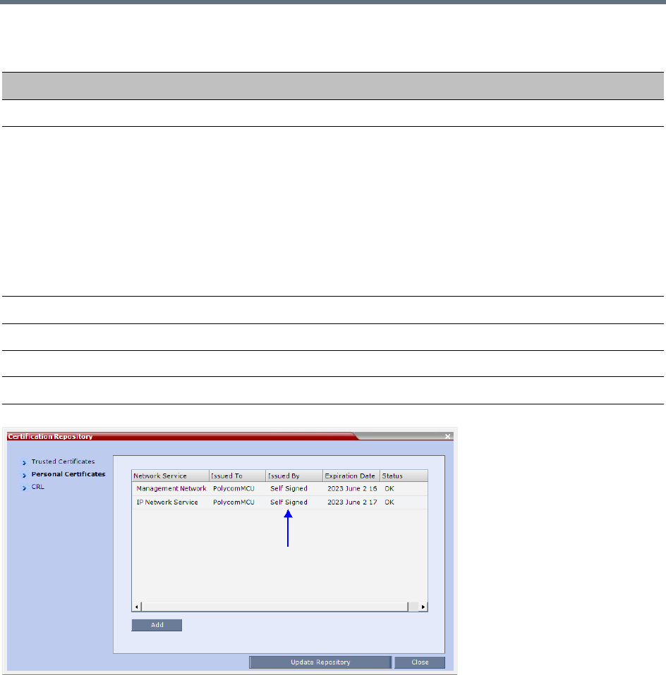
Ultra Secure Mode
Polycom®, Inc. 875
Media Encryption and Authentication
In compliance with UC_APL_SEC_0013, the RMX supports the Privacy Protocols:
●AES_CM_128_HMAC_SHA1_32
●AES_CM_128_HMAC_SHA1_80
System Flag
The Privacy Protocol selection is controlled by the SRTP_SRTCP_HMAC_SHA_LENGH System Flag. To
modify its setting, manually add it to system.cfg and set its value as summarized in the table below.
Self-signed Certificate - Creation
Field Value
Signature Algorithm SHA1
Issuer / Issued To Service Host Name
Both the Issuer and Issued To fields have the same values.
CN = host name of the service name
DC = Polycom
OU = Self Signed Certificate
O = Polycom RMX
Note: The value of CN is derived from the IP Network Service Name, while the
values of DC, OU and O are hard coded.
For a full description of these fields see RFC 5280.
Valid from Date of creation
Valid to Date of creation + 10 years
Subject (Common Name) Service Host Name
Public Key 2048 bits
Ultra Secure Mode
Polycom®, Inc. 876
Range: 80, 32, 80_32
Default: 80
Privacy Protocols - Flag Settings
SRTP_SRTCP_HMAC_SHA_LE
NGH Flag Value
Negotiation Protocol
SDP
Authentication Tag Length
RTP RTCP
80 AES_CM_128_HMAC_SHA1_80 80 80
32 AES_CM_128_HMAC_SHA1_32 32 80
80_32 First:
AES_CM_128_HMAC_SHA1_32
Second:
AES_CM_128_HMAC_SHA1_80
32 or 80
(Depending on
negotiation
result)
80

Polycom®, Inc. 877
Collaboration Server Hardware
Monitoring
The status and properties of the Collaboration Server hardware components can be viewed and monitored
in the Hardware Monitor list pane.
Viewing the Status of the Hardware Components
The Hardware Monitor’s status column displays the present status of the hardware components. In addition
to the status, temperature and voltage indications are provided for each component.
For RMX 1500/2000/4000 systems, the MCU’s Shelf Management Server is what users are connecting to
when accessing the Hardware Monitor pane. This pane can be accessed in either two ways: through the
RMX Web Client or the Shelf Management Server. Connection via the Shelf Management Server enables
users to access the Hardware Monitor even when the connection through the Collaboration Server Web
Client is unavailable. The ability to connect directly via the Shelf Management Server enables users to: enter
the Hardware Monitor and view the problematic hardware components, reset and restart the MCU and run
diagnostics. Running diagnostics and restarting the MCU can only be done via direct connection to the Shelf
Management Server.
•When accessing the Shelf Management server, the content displayed will be available in English
only.
•Shelf Management is not supported on the RMX 1800.
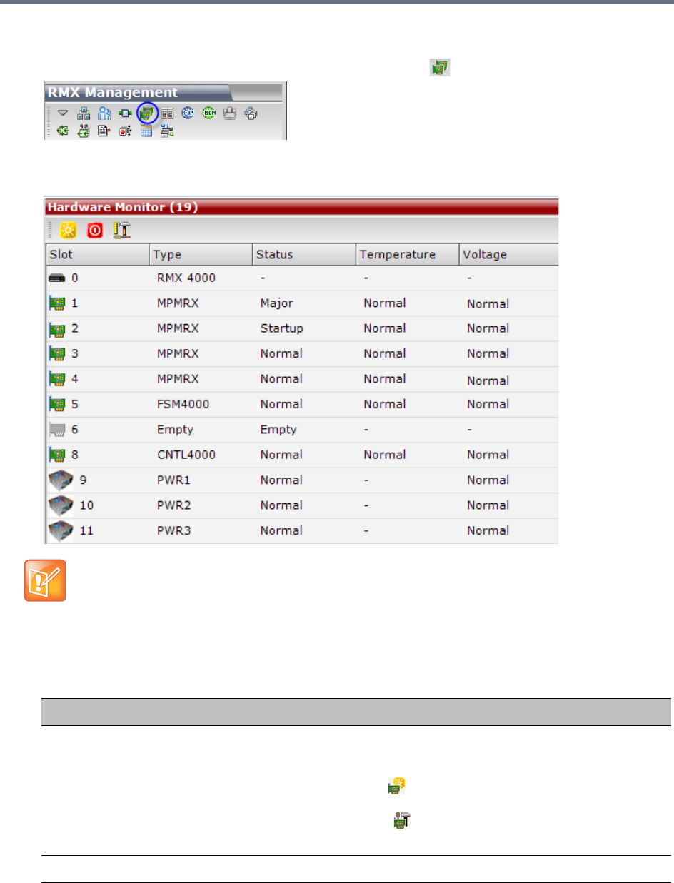
Collaboration Server Hardware Monitoring
Polycom®, Inc. 878
To access Hardware Monitor:
»In the RMX Management pane, click the Hardware Monitor button.
The Hardware Monitor pane displays. Depending on your product model, available hardware
components may vary.
The Hardware Monitor pane displays the following hardware component’s status columns:
In the Hardware Monitor, slots 1 & 2 may sometimes appear as duplicates in the Slot list.
HW Monitor Pane Status Columns
Field Description
Slot Displays an icon according to the HW component type and the slot number. The
icon displays the hardware status as follows:
•An exclamation point (!) indicates errors in the HW component.
•Card icon with the reset button ( ) indicates that the HW component is currently
resetting.
•Card icon with diagnostic tools ( ) indicates that the HW component is in
diagnostic mode.
Type The type of hardware component card.
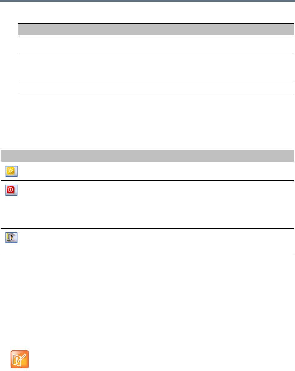
Collaboration Server Hardware Monitoring
Polycom®, Inc. 879
HW Monitor Pane Toolbar
The following buttons appear in the tool bar of the Hardware Monitor. Depending on your product model,
available buttons may vary.
HW Monitor Pane Tool Bar Buttons
Viewing the Properties of Hardware Components
Depending on your product model, available hardware components may vary. The properties displayed for
the hardware components will vary according to the type of component viewed.Hardware component
properties can be grouped as follows:
●MCU Properties
●Card Properties (MPMx / MPMRx, CNTL/CNTL 4000, RTM IP, RTM ISDN, DSP card, RTM LAN,
RTM-IP 4000)
●Supporting Hardware Components Properties (Backplane, FANS, LAN, PWR)
Status The current status of the HW component; Normal, Major, Critical, Resetting,
Diagnostics, or Empty.
Temperature Monitors the temperature of the hardware components; Normal, Major, and
Critical.
Note: Critical condition invokes a system shut down.
Voltage The voltage threshold of the hardware component; either Normal or Major.
Button Name Description
System Reset Resets and restarts the system. Resetting saves settings and information
that you changed in the system, i.e. IP Services, etc...
System Shut Down Shuts down the system into a standby mode. When the user in the
Collaboration Server Manager/Client presses the System Shut Down
(red) button in the Hardware Monitor tool bar, the system should enter a
standby mode and the LED turns ON. Only the media and control unit
cards are in a standby mode. Shelf Manager remains active.
Turn the system OFF/ON to exit the standby mode.
Active Diagnostic Mode Sets the MFA, CPU and switches cards such as MPMx/MPMRx, CNTL
and RTM IP into diagnostic mode. For more information, see Diagnostic
Mode.
No properties are provided for Power Supply (PWR). For more information, see your product
Hardware Guide.
HW Monitor Pane Status Columns
Field Description
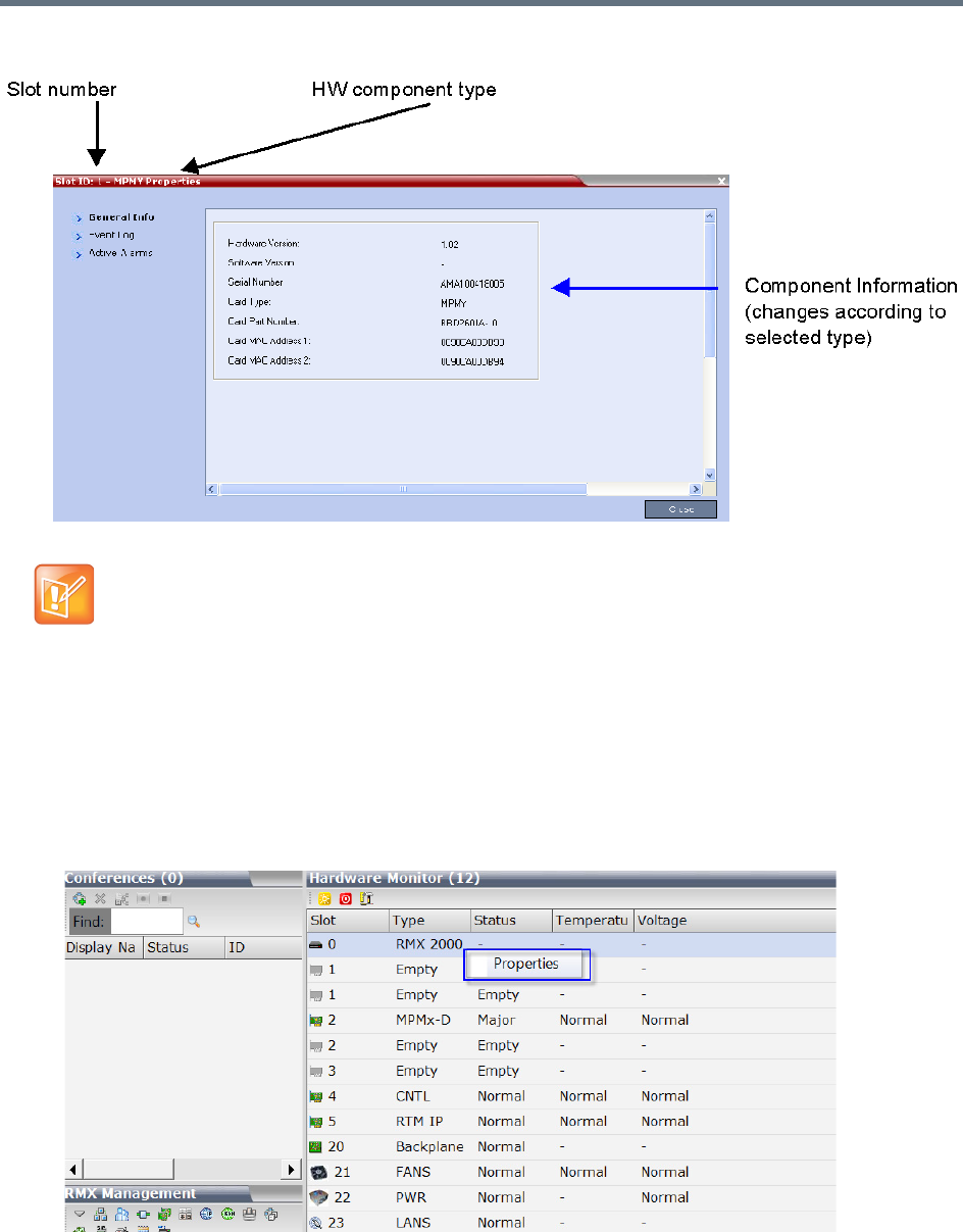
Collaboration Server Hardware Monitoring
Polycom®, Inc. 880
The Hardware Properties dialog box has the following structure:
To view the MCU Properties:
1In the Hardware Monitor pane, right-click your MCU entry, for example, RMX 2000, and select
Properties.
Note: DSP Cards
In Collaboration Server (RMX) 1800, the mapping between DSP media card IDs and the physical slots
is as the following:
•ID 1: Slot 0 (in the middle)
•ID 2: Slot 1 (bottom)
•ID 3: Slot 2 (top)
Collaboration Server (RMX) 1800-0 does not contain DSP cards.
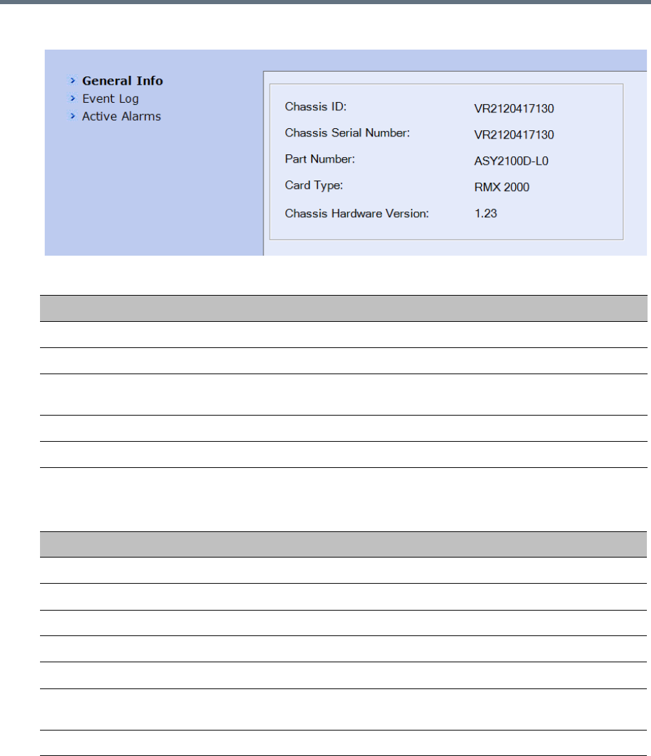
Collaboration Server Hardware Monitoring
Polycom®, Inc. 881
2General information is displayed:
MCU 1500/2000/4000 Properties - General Info
Field Description
Chassis ID The ID assigned to the MCU’s chassis file.
Chassis Serial Number The serial number assigned to the MCU’s chassis.
Part Number The chassis part number. The Part Number contains the letter A/B/C/D that
represents the chassis type.
Card Type The name of the hardware product or component, i.e. RMX 1500, Backplane.
Chassis Hardware Version Indicates the MCU’s current chassis hardware version.
MCU 1800 Properties - General Info
Field Description
Hardware Version The version of the system hardware.
Firmware Version The version of the firmware installed on the system.
Serial Number The serial number of the system hardware.
Card Type Displays the type of the media card that occupies the slot.
Card Part Number The part number of this media card.
Card MAC Address 1 Specific hardware address of the component. This address is burnt onto the
component and is automatically identified by the system.
Card MAC Address 2 (If applicable) second MAC address.
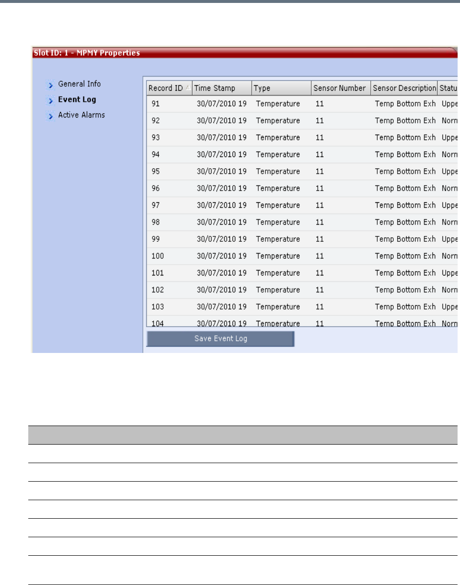
Collaboration Server Hardware Monitoring
Polycom®, Inc. 882
3(RMX 1500/2000/4000 only) Click the Event Log tab to view a log of events that were recorded by
the system.
The logged events can be saved to a *.xls file by clicking the Save Event Log button. It is not possible
to save individual or multiple selected events; the entire log file must be saved.
MCU Properties - Event Log
Column Description
Record ID The recorded ID number of the logged event.
Time Stamp Lists the date and time that the event occurred.
Type Displays the type of event recorded in the log.
Sensor Number The number of the LED sensor on the Collaboration Server unit.
Sensor Description Describes which sensor the event is being logged.
Status The sensor’s active status.
Ipmb Address(hex) Contains all the internal IPMI network addresses on the IPMB bus, i.e. 0x20
(Switch), 0x86 (MFA), etc...
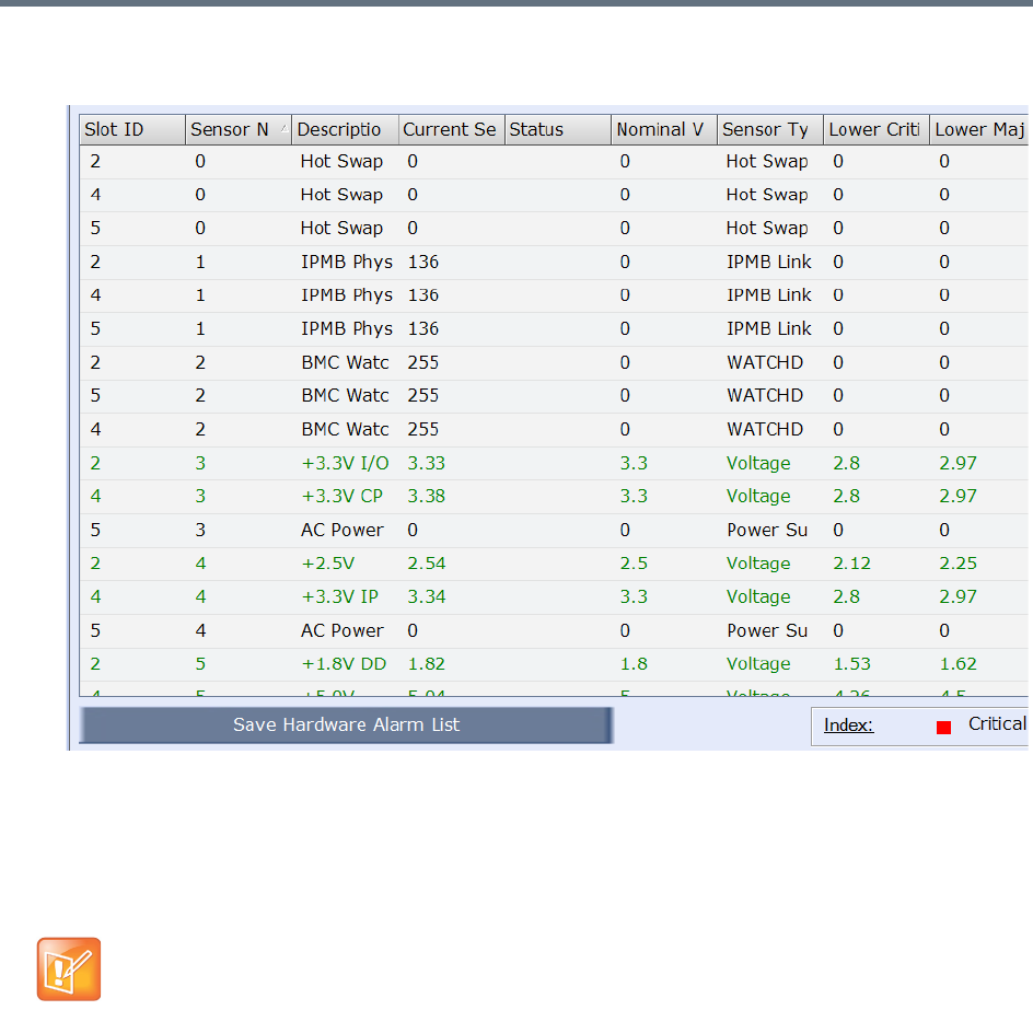
Collaboration Server Hardware Monitoring
Polycom®, Inc. 883
4Click the Active Alarms tab to view alarms related to the Collaboration Server, i.e. temperatures
and main power sensors.
The Active Alarms dialog box displays fields that relate to faults and errors detected on the
Collaboration Server by sensors. The Active Alarms dialog box is divided into two sections:
Hardware Alarm List and Software Alarm List.
Each section’s alarm list can be saved as a *.xls file by clicking the Save Hardware Alarm List and
Save Software Alarm List buttons respectively. Each alarm list color codes the severity of the alarm;
Critical (RED), Major (ORANGE) and Normal (GREEN).
To view a card properties:
1In the Hardware Monitor pane, right-click a desired card and select Properties.
Depending on your card type, available properties may vary.
For RMX 1500/2000/4000 systems, if you are connected to the Hardware Monitoring via the Shelf
Management server, the Software Alarm List section will not be displayed.
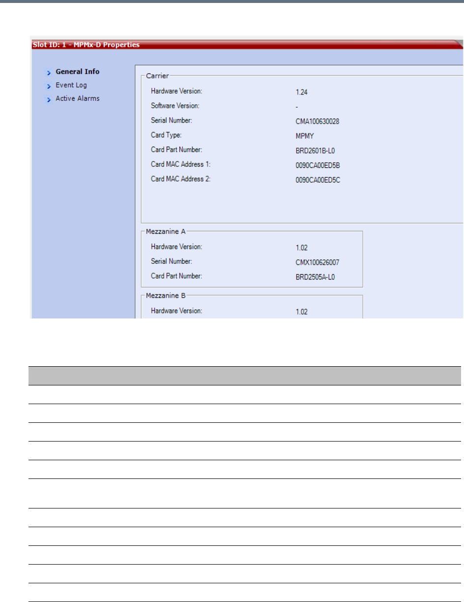
Collaboration Server Hardware Monitoring
Polycom®, Inc. 884
2The card property window may look like this:
Depending on the card type, the following information may be available:
Card Properties - General Info
Field Description
Hardware Version The hardware component’s version number.
Software Version The version number of the software installed on card.
Serial Number The hardware component’s serial number.
Card Type Displays the type of card that occupies the slot.
Card Part Number The part number of the HW component’s board.
Card Mac Address 1 Specific hardware address of the component. This address is burnt onto the
component and is automatically identified by the system.
Card MAC Address 2 (If applicable) second MAC address.
Mezzanine x
Hardware Version The Mezzanine x hardware component’s version number.
Serial Number The Mezzanine x hardware component’s serial number.
Card Part Number The part number of the Mezzanine x hardware component’s board.

Collaboration Server Hardware Monitoring
Polycom®, Inc. 885
3Click the Event Log tab (if any) to view a log of events recorded by the system on the HW
component.
4Click the Active Alarms tab (if any) to view alarms related to the hardware component, i.e.
temperatures and main power sensors.
For more information, see Appendix B - Active Alarms.
5Click Close to return to the Hardware Monitor pane.
To view the supporting hardware components properties:
»In the Hardware Monitor pane, right-click and select Properties for the desired supporting hardware
component.
The component’s properties dialog box will appear with the General Info tab displayed.
View Backplane Properties
The Collaboration Server unit’s backplane properties provides the following information:
View FAN Properties
The Collaboration Server unit’s chassis contains 3 fans that regulate the unit’s temperature. If the
temperature increases, the fans speed will increase and vice-versa. A “Critical” condition in the fans
operation will result in a system shut down.
Backplane Properties - General Info
Field Description
HW Version The Backplane’s current hardware version.
SW Version The Backplane’s current software version.
Serial Number The Backplane’s serial number.
Card Type The name of the hardware component for which information is displayed, e.g.
Backplane.
Card Part Number The Backplane’s part number.
Card MAC Address 1 The Backplane’s hardware address.
Card MAC Address 2 (If applicable) second Backplane MAC address.
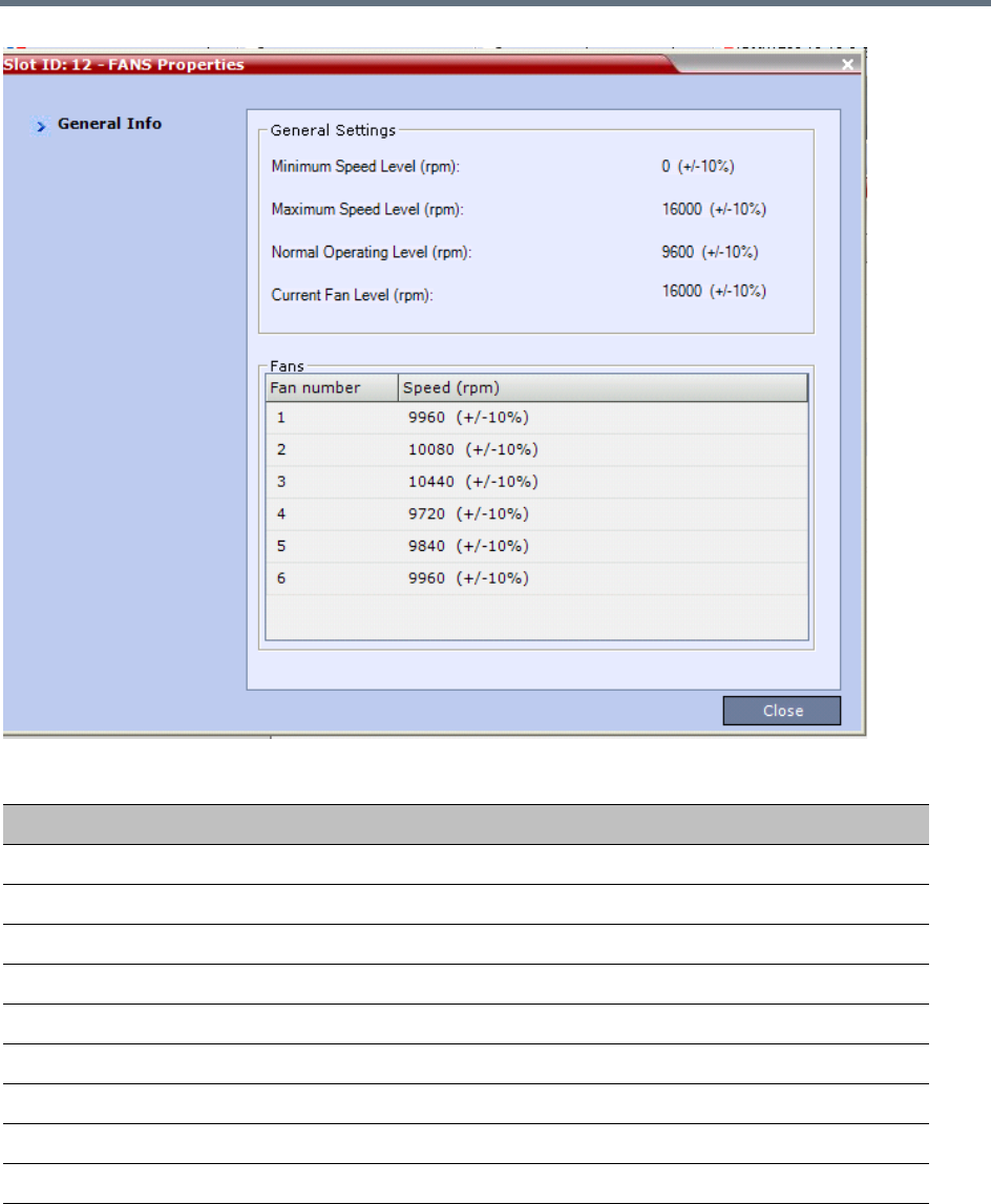
Collaboration Server Hardware Monitoring
Polycom®, Inc. 886
FAN Properties - General Info
Field Description
General Settings
Min. Speed Level (rpm) The minimum speed level of the fans.
Max. Speed Level (rpm) The maximum speed level of the fans.
Normal Operating Level (rpm) The normal operating level defined for the fans.
Current Fan Level (rpm) The current operating level of the fans.
Fans
Fan 1 Speed (rpm) Present speed of fan 1.
Fan 2 Speed (rpm) Present speed of fan 2.
Fan 3 Speed (rpm) Present speed of fan 3.
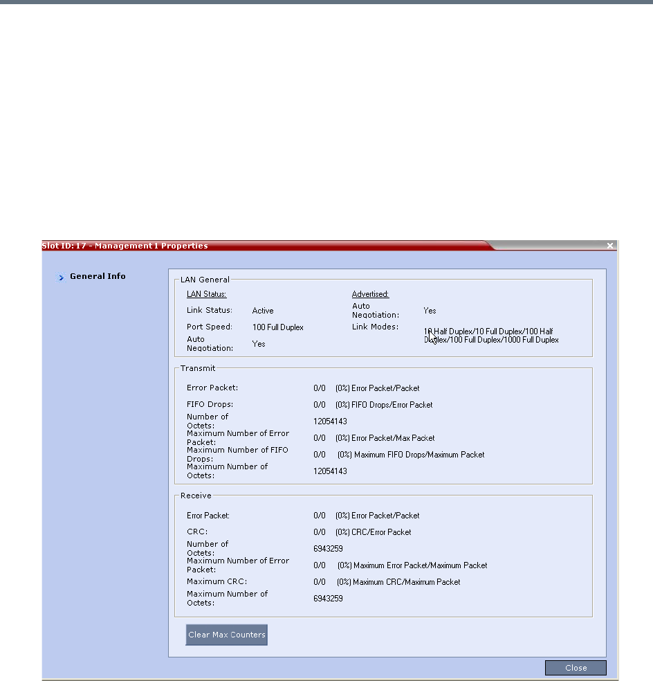
Collaboration Server Hardware Monitoring
Polycom®, Inc. 887
View LAN Properties
Depending on your product model, a Collaboration Server may contain various numbers of external LAN
connectors.
To view a LAN connector properties:
1In the Hardware Monitor pane, double-click LANS.
The LAN list opens.
2Double-click a desired LAN to view its properties.
The information will be refreshed every eight seconds and also contains a peek detector to log the
maximal values, since the last peek values reset.
Temperature Thresholds
On each Collaboration Server card or there are temperature sensors that are placed near specific
components on the media card. In the Hardware Monitor you can view the properties of each card together
with their temperature statuses. By right clicking on any card and viewing the cards Properties, the Active
Alarms tab displays all the card sensors, their statuses and lists each sensor’s temperature specifications.
When the temperature on the cards initially rises, a fault could be triggered and can viewed in the System
Alerts, Faults List. Load issues can arise when the system nears the maximum conference mark or high port
capacity occurs on an Collaboration Server resulting in Upper Major or Upper Critical faults.
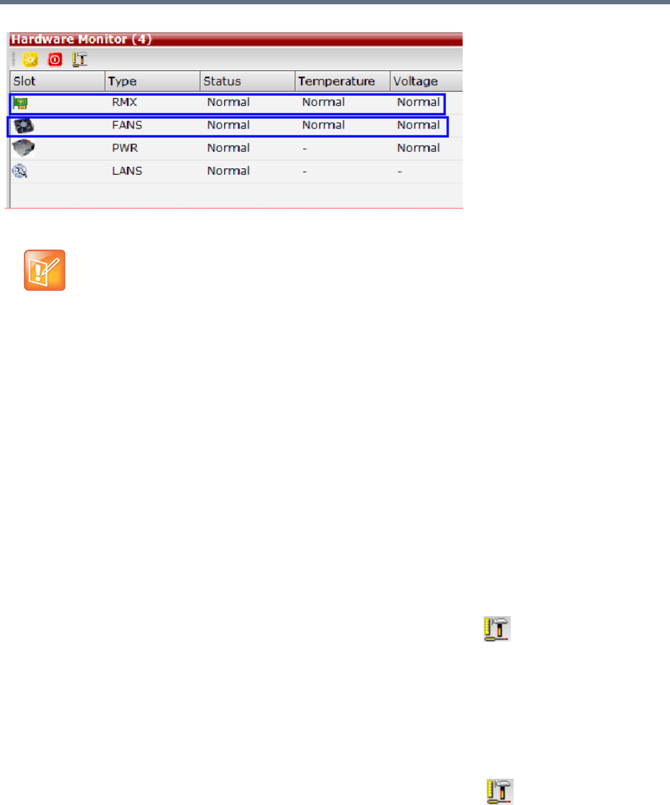
Collaboration Server Hardware Monitoring
Polycom®, Inc. 888
Diagnostic Mode
Diagnostic Mode is a debugging tool for performing hardware diagnostics that detect malfunctions in the
hardware component’s performance. Diagnostics are performed only for the MFA, CPU and Switch (Cards:
MPMx/MPMRx, DSP media cards, CPU, RTM IP, and RTM ISDN).
A user using an Administrator Login can view and access the Diagnostic Mode. When Diagnostic Mode is
initialized, the MCU is reset and upon restarting, the MCU will enter Diagnostic Mode. Entering this mode
causes the MCU to terminate all active conferences and prohibits conferences from being established.
RMX 1500/2000/4000 Administrator users must access the system in Diagnostic Mode using the system
Shelf Management IP address.
To run Diagnostics on a card:
1On the Hardware Monitor toolbar, click the Active Diagnostic Mode button.
2If asked whether to continue this operation, click Yes.
3The Collaboration Server restarts.
4For RMX 1500/2000/4000, the web client reopens using the Shelf Manager IP address; For RMX
1800, you need to re-enter the system management IP in the browser to access the web client
again.
5Log in using an Administrator account.
6On the Hardware Monitor toolbar, click the Active Diagnostic Mode( ) button.
With an Upper Major alarm activation it is recommended to perform the following checks:
•Fans/fan tray functions
•Overall System Ventilation
•Filter (top, bottom & sides free and no dust)
•Room temperature (cool).
When no apparent cause can be found, then contact your next level of support.
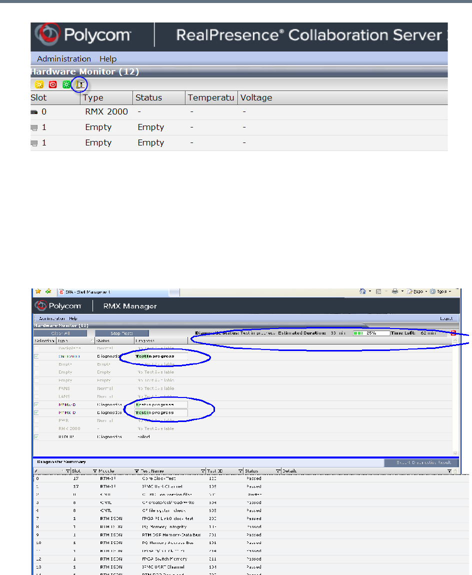
Collaboration Server Hardware Monitoring
Polycom®, Inc. 889
7When asked whether to continue, click Yes.
8The Collaboration Server resets and enters the Diagnostic mode.
9For RMX 1500/2000/4000, the web client reopens using the Shelf Manager IP address; For RMX
1800, you need to re-enter the system management IP in the browser to access the web client
again.
10 Log in again using an Administrator account.
11 To run diagnostics on one or several cards, select the desired cards and select Run Tests.
12 You can view diagnostic status, progress, and summary from the Hardware Monitor pane.
13 To stop the diagnostic tests, click Stop Tests.
14 When the tests are completed, you can download a report in Excel format for analysis by your next
level of support by clicking the Export Diagnostics Result button.
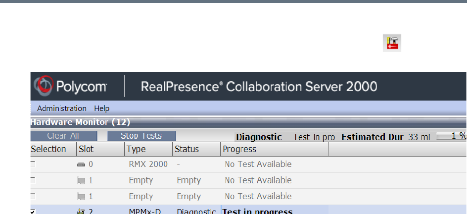
Collaboration Server Hardware Monitoring
Polycom®, Inc. 890
To exit the Diagnostics Mode:
»To exit the Diagnostic Mode and reset the system to normal working status, click on the
upper-right of the Hardware Monitor window.

Polycom®, Inc. 891
Appendix A - Disconnection Causes
If a participant was unable to connect to a conference or was disconnected from a conference, the
Connection Status tab in the Participant Properties dialog box indicates the call disconnection cause. In
some cases, a possible solution may be displayed.
A video participant who is unable to connect the video channels, but is able to connect as an audio only
participant, is referred to as a Secondary participant. For Secondary participants, the Connection Status tab
in the Participant Properties dialog box indicates the video disconnection cause. In some cases, a possible
solution may be indicated.
The table below lists the call disconnection causes that can be displayed in the Call Disconnection Cause
field and provides an explanation of each message
IP Disconnection Causes
Call Disconnection Causes
Disconnection Cause Description
Disconnected by User The user disconnected the endpoint from the conference.
Remote device did not open the
encryption signaling channel
The endpoint did not open the encryption signaling channel.
Remote devices selected encryption
algorithm does not match the local
selected encryption algorithm
The encryption algorithm selected by the endpoint does not match the
MCU's encryption algorithm.
Resources deficiency Insufficient resources available.
Call close. Call closed by MCU The MCU disconnected the call.
H323 call close. No port left for audio Insufficient audio ports.
H323 call close. No port left for video The required video ports exceed the number of ports allocated to video
in fixed ports.
H323 call close. No port left for FECC The required data ports exceed the number of ports allocated to data in
fixed ports.
H323 call close. No control port left The required control ports exceed the number of ports allocated to
control data in fixed ports.
H323 call close. No port left for videocont The required video content ports exceed the number of ports allocated
to video content in fixed ports.
H323 call closed. Small bandwidth The gatekeeper allocated insufficient bandwidth to the connection with
the endpoint.
H323 call closed. No port left There are no free ports left in the IP card.

Appendix A - Disconnection Causes
Polycom®, Inc. 892
Caller not registered The calling endpoint is not registered in the gatekeeper.
H323 call closed. ARQ timeout The endpoint sent an ARQ message to the gatekeeper, but the
gatekeeper did not respond before timeout.
H323 call closed. DRQ timeout The endpoint sent a DRQ message to the gatekeeper, but the
gatekeeper did not respond before timeout.
H323 call closed. Alt Gatekeeper failure An alternate gatekeeper failure occurred.
H323 call closed. Gatekeeper failure A gatekeeper failure occurred.
H323 call closed. Remote busy The endpoint was busy. (Applicable only to dial-out)
H323 call closed. Normal The call ended normally, for example, the endpoint disconnected.
H323 call closed. Remote reject The endpoint rejected the call.
H323 call closed. Remote unreachable The call remained idle for more than 30 seconds and was
disconnected because the destination device did not answer. Possible
causes can be due to network problems, the gatekeeper could not find
the endpoint's address, or the endpoint was busy or unavailable (for
example, the “do not disturb” status is selected).
H323 call closed. Unknown reason The reason for the disconnection is unknown, for example, the
endpoint disconnected without giving a reason.
H323 call closed. Faulty destination
address
Incorrect address format.
H323 call closed. Small bandwidth The gatekeeper allocated insufficient bandwidth to the connection with
the endpoint.
H323 call closed. Gatekeeper reject
ARQ
The gatekeeper rejected the endpoint's ARQ.
H323 call closed. No port left There are no ports left in the IP card.
H323 call closed. Gatekeeper DRQ The gatekeeper sent a DRQ.
H323 call closed. No destination IP
address
For internal use.
H323 call. Call failed prior or during the
capabilities negotiation stage
The endpoint did not send its capabilities to the gatekeeper.
H323 call closed. Audio channels didn't
open before timeout
The endpoint did not open the audio channel.
H323 call closed. Remote sent bad
capability
There was a problem in the capabilities sent by the endpoint.
H323 call closed. Local capability wasn't
accepted by remote
The endpoint did not accept the capabilities sent by the gatekeeper.
H323 failure Internal error occurred.
Call Disconnection Causes
Disconnection Cause Description

Appendix A - Disconnection Causes
Polycom®, Inc. 893
H323 call closed. Remote stop
responding
The endpoint stopped responding.
H323 call closed. Master slave problem A People + Content cascading failure occurred.
SIP bad name The conference name is incompatible with SIP standards.
SIP bad status A general IP card error occurred.
SIP busy everywhere The participant's endpoints were contacted successfully, but the
participant is busy and does not wish to take the call at this time.
SIP busy here The participant's endpoint was contacted successfully, but the
participant is currently not willing or able to take additional calls.
SIP capabilities don't match The remote device capabilities are not compatible with the conference
settings.
SIP card rejected channels The IP card could not open the media channels.
SIP client error 400 The endpoint sent a SIP Client Error 400 (Bad Request) response.
The request could not be understood due to malformed syntax.
SIP client error 402 The endpoint sent a SIP Client Error 402 (Payment Required)
response.
SIP client error 405 The endpoint sent a SIP Client Error 405 (Method Not Allowed)
response.
The method specified in the Request-Line is understood, but not
allowed for the address identified by the Request-URI.
SIP client error 406 The endpoint sent a SIP Client Error 406 (Not Acceptable) resources.
The remote endpoint cannot accept the call because it does not have
the necessary responses. The resource identified by the request is
only capable of generating response entities that have content
characteristics not acceptable according to the Accept header field
sent in the request.
SIP client error 407 The endpoint sent a SIP Client Error 407 (Proxy Authentication
Required) response.
The client must first authenticate itself with the proxy.
SIP client error 409 The endpoint sent a SIP Client Error 409 (Conflict) response.
The request could not be completed due to a conflict with the current
state of the resource.
SIP client error 411 The endpoint sent a SIP Client Error 411 (Length Required) response.
The server refuses to accept the request without a defined Content
Length.
Call Disconnection Causes
Disconnection Cause Description

Appendix A - Disconnection Causes
Polycom®, Inc. 894
SIP client error 413 The endpoint sent a SIP Client Error 413 (Request Entity Too Large)
response.
The server is refusing to process a request because the request entity
is larger than the server is willing or able to process.
SIP client error 414 The endpoint sent a SIP Client Error 414 (Request-URI Too Long)
response.
The server is refusing to service the request because the Request-URI
is longer than the server is willing to interpret.
SIP client error 420 The endpoint sent a SIP Client Error 420 (Bad Extension) response.
The server did not understand the protocol extension specified in a
Require header field.
SIP client error 481 The endpoint sent a SIP Client Error 481 (Call/Transaction Does Not
Exist) response.
SIP client error 482 The endpoint sent a SIP Client Error 482 (Loop Detected) response.
SIP client error 483 The endpoint sent a SIP Client Error 483 (Too Many Hops) response.
SIP client error 484 The endpoint sent a SIP Client Error 484 (Address Incomplete)
response.
The server received a request with a To address or Request-URI that
was incomplete.
SIP client error 485 The endpoint sent a SIP Client Error 485 (Ambiguous) response.
The address provided in the request (Request-URI) was ambiguous.
SIP client error 488 The endpoint sent a SIP Client Error 488 (Not Acceptable Here)
response.
SIP forbidden The SIP server rejected the request.
The server understood the request, but is refusing to fulfill it.
SIP global failure 603 A SIP Global Failure 603 (Decline) response was returned.
The participant's endpoint was successfully contacted, but the
participant explicitly does not wish to or cannot participate.
SIP global failure 604 A SIP Global Failure 604 (Does Not Exist Anywhere) response was
returned.
The server has authoritative information that the user indicated in the
Request-URI does not exist anywhere.
SIP global failure 606 A SIP Global Failure 606 (Not Acceptable) response was returned.
SIP gone The requested resource is no longer available at the Server and no
forwarding address is known.
SIP moved permanently The endpoint moved permanently. The user can no longer be found at
the address in the Request-URI.
SIP moved temporarily The remote endpoint moved temporarily.
Call Disconnection Causes
Disconnection Cause Description

Appendix A - Disconnection Causes
Polycom®, Inc. 895
SIP not found The endpoint was not found.
The server has definitive information that the user does not exist at the
domain specified in the Request-URI.
SIP redirection 300 A SIP Redirection 300 (Multiple Choices) response was returned.
SIP redirection 305 A SIP Redirection 305 (Use Proxy) response was returned.
The requested resource MUST be accessed through the proxy given
by the Contact field.
SIP redirection 380 A SIP Redirection 380 (Alternative Service) response was returned.
The call was not successful, but alternative services are possible.
SIP remote cancelled call The endpoint canceled the call.
SIP remote closed call The endpoint ended the call.
SIP remote stopped responding The endpoint is not responding.
SIP remote unreachable The endpoint could not be reached.
SIP request terminated The endpoint terminated the request.
The request was terminated by a BYE or CANCEL request.
SIP request timeout The request was timed out.
SIP server error 500 The SIP server sent a SIP Server Error 500 (Server Internal Error)
response.
The server encountered an unexpected condition that prevented it from
fulfilling the request.
SIP server error 501 The SIP server sent a SIP Server Error 501 (Not Implemented)
response.
The server does not support the functionality required to fulfill the
request.
SIP server error 502 The SIP server sent a SIP Server Error 502 (Bad Gateway) response.
The server, while acting as a gateway or proxy, received an invalid
response from the downstream server it accessed in attempting to fulfill
the request.
SIP server error 503 The SIP server sent a SIP Server Error 503 (Service Unavailable)
response.
The server is temporarily unable to process the request due to a
temporary overloading or maintenance of the server.
SIP server error 504 The SIP server sent a SIP Server Error 504 (Server Time-out)
response.
The server did not receive a timely response from an external server it
accessed in attempting to process the request.
Call Disconnection Causes
Disconnection Cause Description

Appendix A - Disconnection Causes
Polycom®, Inc. 896
ISDN Disconnection Causes
SIP server error 505 The SIP server sent a SIP Server Error 505 (Version Not Supported)
response.
The server does not support, or refuses to support, the SIP protocol
version that was used in the request.
SIP temporarily not available The participant's endpoint was contacted successfully but the
participant is currently unavailable (e.g., not logged in or logged in such
a manner as to preclude communication with the participant).
SIP remote device did not respond in the
given time frame
The endpoint did not respond in the given time frame.
SIP trans error TCP Invite A SIP Invite was sent via TCP, but the endpoint was not found.
SIP transport error Unable to initiate connection with the endpoint.
SIP unauthorized The request requires user authentication.
SIP unsupported media type The server is refusing to service the request because the message
body of the request is in a format not supported by the requested
resource for the requested method.
ISDN Disconnection Causes
Number Summary Description
1 Unallocated (unassigned
number)
No route to the number exists in the ISDN network or the number was
not found in the routing table.
•Ensure that the number appears in the routing table.
•Ensure that it is a valid number and that correct digits were dialed.
2 No route to specified transit
network (national use)
The route specified (transit network) between the two networks does
not exist.
3 No route to destination No physical route to the destination number exists although the dialed
number is in the routing plan.
•The PRI D-Channel is malfunctioning.
•Incorrect connection of the span or WAN.
4 Send special information
tone
Return the special information tone to the calling party indicating that
the called user cannot be reached.
5 Misdialed trunk prefix
(national use)
A trunk prefix has erroneously been included in the called user number.
6 Channel Unacceptable The sending entity in the call does not accept the channel most
recently identified.
Call Disconnection Causes
Disconnection Cause Description

Appendix A - Disconnection Causes
Polycom®, Inc. 897
7 Call awarded and being
delivered in an Established
channel
The incoming call is being connected to a channel previously
established for similar calls.
8 Pre-Emption The call has been pre-empted.
9 Pre-Emption – Circuit
reserved for reuse
Call is being cleared in response to user request.
16 Normal Call Clearing Call cleared normally because user hung up.
17 User Busy Dialed number is busy.
18 No User Responding The called user has not answered the call.
19 No Answer from User
(User Alerted)
Called user has received call alert, but has not responded within a
prescribed period of time. Internal network timers may initiate this
disconnection.
20 Subscriber Absent User is temporarily absent from the network - as when a mobile user
logs off.
21 Call Rejected Called number is either busy or has compatibility issues.
Supplementary service constraints in the network may also initiate the
disconnection.
22 Number Changed Same as Cause 1. The diagnostic field contains the new called user
number. Cause 1 is used if the network does not support this cause
value.
26 Non-Selected User
Clearing
The incoming call has not been assigned to the user.
27 Destination Out-of-Order Messages cannot be sent to the destination number because the span
may not be active.
28 Invalid Number Format
(address incomplete)
The Type of Number (TON) is incorrect or the number is incomplete.
Network, Unknown and National numbers have different formats.
29 Facility Rejected User requested supplementary service which cannot be provided by
the network.
30 Response to STATUS
ENQUIRY
A STATUS message has been received in response to a prior STATUS
ENQUIRY.
31 Normal, Unspecified A normal, unspecified disconnection has occurred.
34 No Circuit/Channel
Available
No B-Channels are available for the call.
38 Network Out-of-Order Network is out-of-order because due to a major malfunction.
39 Permanent Frame Mode
Connection Out-of-Service
A permanent frame mode connection is out-of-service. This cause is
part of a STATUS message.
ISDN Disconnection Causes
Number Summary Description

Appendix A - Disconnection Causes
Polycom®, Inc. 898
40 Permanent Frame Mode
Connection Operational
A permanent frame mode connection is operational. This cause is part
of a STATUS message.
41 Temporary Failure Minor network malfunction. Initiate call again.
42 Switching Equipment
Congestion
High traffic has congested the switching equipment. Cause 43 is
included.
43 Access Information
Discarded
Access Information elements exceed maximum length and have been
discarded. Included with Cause 42.
44 Requested Circuit/Channel
not Available
The requested circuit or channel is not available. Alternative circuits or
channels are not acceptable.
47 Resource Unavailable,
Unspecified
The resource is unavailable. No other disconnection cause applies.
49 Quality of Service Not
Available
Quality of Service, as defined in Recommendation X.213, cannot be
provided.
50 Requested Facility Not
Subscribed
A supplementary service has been requested that the user is not
authorized to use.
53 Outgoing Calls Barred
Within Closed User Group
(CUG)
Outgoing calls are not permitted for this member of the CUG.
55 Incoming Calls Barred
within CUG
Incoming calls are not permitted for this member of the CUG.
57 Bearer Capability Not
Authorized
A bearer capability has been requested that the user is not authorized
to use.
58 Bearer Capability Not
Presently Available
A bearer capability has been requested that the user is not presently
available.
62 Inconsistency in
Designated Outgoing
Access Information and
Subscriber Class
Outgoing Access and Subscriber Class information is inconsistent
63 Service or Option Not
Available, Unspecified
The service or option is unavailable. No other disconnection cause
applies.
65 Bearer Capability Not
Implemented
The requested bearer capability is not supported.
66 Channel Type Not
Implemented
The requested channel type is not supported.
69 Requested Facility Not
Implemented
The requested supplementary service is not supported.
ISDN Disconnection Causes
Number Summary Description

Appendix A - Disconnection Causes
Polycom®, Inc. 899
70 Only Restricted Digital
Information Bearer
Capability is Available
(national use)
Unrestricted (64kb) bearer service has been requested but is not
supported by the equipment sending this cause.
79 Service or Option Not
Implemented, Unspecified
An unsupported service or unimplemented option has been requested.
No other disconnection cause applies.
81 Invalid Call Reference
Value
A message has been received which contains a call reference which is
currently unassigned or not in use on the user-network interface.
82 Identified Channel Does
Not Exist
A request has been received to use a channel which is currently
inactive or does not exist.
83 A Suspended Call Exists,
but This Call Identity Does
Not Exist
A RESUME message cannot be executed by the network as a result of
an unknown call identity.
84 Call Identity in Use A SUSPEND message has been received with a call identity sequence
that is already in use.
85 No Call Suspended A RESUME message cannot be executed by the network as a result of
no call suspended.
86 Call Having the Requested
Call Identity Has Been
Cleared
A RESUME message cannot be executed by the network as a result of
the call having been cleared while suspended.
87 User Not Member of CUG A CUG member was called by a user who is not a member of the CUG
or a CUG call was made to a non CUG member.
88 Incompatible Destination User-to-user compatibility checking procedures in a point-to-point data
link have determined that an incompatibility exists between Bearer
capabilities.
90 Non-Existent CUG CUG does not exist.
91 Invalid Transit Network
Selection (national use)
The transit network selection is of an incorrect format. No route (transit
network) exists between the two networks.
95 Invalid Message,
Unspecified
Invalid message received. No other disconnection cause applies.
96 Mandatory Information
Element is Missing
A message was received with an information element missing.
97 Message Type
Non-Existent or Not
Implemented
A message was received that is of a type that is not defined or of a type
that is defined but not implemented.
98 Message is Not Compatible
with the Call State, or the
Message Type is
Non-Existent or Not
Implemented
An unexpected message or unrecognized message incompatible with
the call state has been received
ISDN Disconnection Causes
Number Summary Description
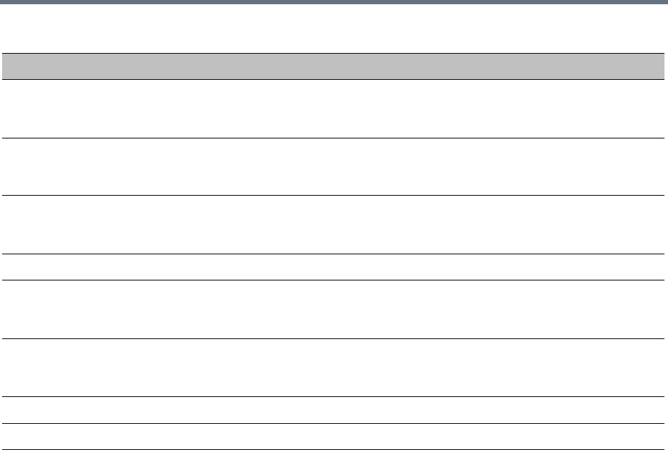
Appendix A - Disconnection Causes
Polycom®, Inc. 900
99 An Information Element or
Parameter Does Not Exist
or is Not Implemented
A message was received containing elements or parameters that are
not defined or of a type that is defined but not implemented.
100 Invalid Information Element
Contents
A message other than SETUP, DISCONNECT, RELEASE, or
RELEASE COMPLETE has been received which has one or more
mandatory information elements containing invalid content.
101 The Message is Not
Compatible with the Call
State
A STATUS message indicating any call state except the Null state has
been received while in the Null state.
102 Recovery on Timer Expired An error handling procedure timer has expired.
103 Parameter Non-Existent or
Not Implemented – Passed
On (national use)
A message was received containing parameters that are not defined or
of a type that is defined but not implemented.
110 Message with
Unrecognized Parameter
Discarded
A message was discarded because it contained a parameter that was
not recognized.
111 Protocol Error, Unspecified A protocol error has occurred. No other disconnection cause applies.
127 Interworking, Unspecified An interworking call has ended.
ISDN Disconnection Causes
Number Summary Description

Polycom®, Inc. 901
Appendix B - Active Alarms
Active Alarms
Alarm Code Alarm Description
A matching activation key is required.
To cancel the upgrade process, reset
the Collaboration Server
The system upgrade requires that a valid activation key be entered. If
none is available, resetting the Collaboration Server will cancel the
upgrade and return the Collaboration Server to the previous version.
A new activation key was loaded.
Reset the system.
A new activation key was loaded: Reset the MCU.
A new version was installed. Reset the
system.
A new version was installed: Reset the MCU.
Alarm generated by a Central
Signaling component
A system alert was generated by a component of the Central Signaling.
Alarm generated by an internal
component
A system alert was generated by an internal system component.
Allocation mode was modified
Automatic reset is unavailable in Safe
Mode
The system switches to safe mode if many resets occur during startup. To
prevent additional resets, and allow the system to complete the startup
process the automatic system resets are blocked.
Backup of audit files is required If the ENABLE_CYCLIC_FILE_SYSTEM_ALARMS is set to YES (default
setting when ULTRA_SECURE_MODE System Flag is set to YES) and a
Cyclic File reaches a file retention time or file storage capacity limit, the
user is alerted that audit files need to be backed up.
Backup of CDR files is required If the ENABLE_CYCLIC_FILE_SYSTEM_ALARMS is set to YES (default
setting when ULTRA_SECURE_MODE System Flag is set to YES) and a
Cyclic File reaches a file retention time or file storage capacity limit, the
user is alerted that CDR files need to be backed up.
Backup of log files is required If the ENABLE_CYCLIC_FILE_SYSTEM_ALARMS is set to YES (default
setting when ULTRA_SECURE_MODE System Flag is set to YES) and a
Cyclic File reaches a file retention time or file storage capacity limit, the
user is alerted that log files need to be backed up.
Bios version is not compatible with
Ultra Secure Mode.
The current BIOS version is not compatible with Ultra Secure Mode
(ULTRA_SECURE_MODE=YES).
Card configuration event
Card failed to switch to Enhanced
Secure Mode
Card failure occurred when the system was set to Ultra Secure Mode
(ULTRA_SECURE_MODE=YES).

Appendix B - Active Alarms
Polycom®, Inc. 902
Card failure Possible reasons for the card failure:
•Resetting Card
•Resetting component
•Unknown shelf error
•Unknown card error
Card not found This occurs when: the system does not receive an indication about the
card (since it does not exist…) usually when the card was removed from
the MCU and the system did not have a chance to recalculate it
resources.
Card not responding Possible reasons for the card not responding:
•No connection with MPM card.
•No connection with the Switch.
Cards wrong file's mode
Central signaling component failure Possible explanations:
•Central signaling component failure; unit type:
[NonComponent\CSMngnt\CSH323\CSSIP]
•Central signaling component failure; unit type: (invalid:
[NonComponent\CSMngnt\CSH323\CSSIP])
•Central signaling component failure - Invalid failure type. Unit id: [id],
Type: [NonComponent\CSMngnt\CSH323\CSSIP], Status:
[Ok\Failed\Recovered]
•Central signaling component failure - Invalid failure type
Central Signaling indicating Faulty
status
Central signaling failure detected in IP Network Service.
Central Signaling indicating Recovery
status
Central Signaling startup failure Central Signaling component is down.
Conference Encryption Error
Configuration of external database did
not complete.
Check the configuration of the external DB.
Could not complete MPM Card startup
procedure
Possible explanations:
•Unit loading confirmation was not received.
•No Media IP for this card.
•Media IP Configuration confirmation was not received.
•Unspecified problem.
Check the card slot and reset the card.
Could not complete RTM ISDN Card
startup procedure
The RTM ISDN card cannot complete its startup procedure (usually after
system reset).
Check the card slot and reset the card.
Active Alarms
Alarm Code Alarm Description

Appendix B - Active Alarms
Polycom®, Inc. 903
CPU IPMC software was not updated. Turn off the MCU and then turn it on.
CPU slot ID not identified The CPU slot ID required for Ethernet Settings was not provided by the
Shelf Management.
D channel cannot be established
DEBUG mode enabled Possible explanations:
•System is running in DEBUG mode.
•System DEBUG mode initiated.
In this mode, additional prints are added and Startup and Recovery
Conditions are different then Non Debug Mode.
Change the DEBUG_MODE flag value to NO and reset the Collaboration
Server.
DEBUG mode flags in use The system is using the DEBUG CFG flags.
DMA not supported by IDE device Possible explanations:
•DMA (direct memory access) not supported by IDE device:
Incompatible flash card / hard disk being used.
•Flash card / hard drive are not properly connected to the board / one
of the IDE channels is disconnected.
•DMA was manually disabled for testing.
DNS configuration error Check the DNS configuration.
DNS not configured in IP Network
Service
Configure the DNS in the IP Network Services.
Encryption Server Error. Failed to
generate the encryption key
FIPS 140 test failed while generating the new encryption key.
Error in external database certificate
Error reading MCU time Failed to read MCU time configuration file ([status]).
Manually configure the MCU Time in the Collaboration Server Web Client
or RMX Manager Manager application.
eUserMsgCode_Cs_EdgeServerDnsF
ailed
eUserMsgCode_Cs_SipTLS_Certificat
eHasExpired
eUserMsgCode_Cs_SipTLS_Certificat
eSubjNameIsNotValid_Or_DnsFailed
eUserMsgCode_Cs_SipTLS_Certificat
eWillExpireInLessThanAWeek
eUserMsgCode_Cs_SipTLS_FailedTo
LoadOrVerifyCertificateFiles
Active Alarms
Alarm Code Alarm Description

Appendix B - Active Alarms
Polycom®, Inc. 904
eUserMsgCode_Cs_SipTLS_Registrat
ionHandshakeFailure
eUserMsgCode_Cs_SipTLS_Registrat
ionServerNotResponding
Event Mode Conferencing resources
deficiency due to inappropriate license.
Please install a new license
External NTP servers failure The MCU could not connect to any of the defined NTP server for
synchronization due to the remote server error or network error or
configuration error.
Change the configuration of the NTP server.
Failed to access DNS server Failed to access DNS server.
Failed to configure the Media card IP
address
Possible reasons for the failure:
•Failure type: [OK Or Not supported.
•Does not exist Or IP failure.
•Duplicate IP Or DHCP failure.
•VLAN failure Or Invalid: [status_Number].
Failed to configure the Users list in
Linux
The authentication process did not start.
Use the Restore to factory Defaults to recover.
Failed to connect to application server Possible reasons for the failure:
•Failed to connect to application server:
•Failed to establish connection to server, url = [url].
Failed to connect to recording device The MCU could not connect to the defined recording device due to
configuration error or network error.
Failed to connect to SIP registrar Cannot establish connection with SIP registrar.
Failed to create Default Profile Possible reasons for the failure:
•Failed to validate the default Profile.
•Failed to add the default Profile.
Possible action:
•Restore the Collaboration Server configuration from the Backup.
•Use the Non-Comprehensive Restore To Factory Defaults operation.
Failed to initialize system base mode
Failed to initialize the file system Possible reasons for the failure:
•Failed to initialize the file system.
•Failed to initialize the file system and create the CDR index.
Reset the MCU.
Failed to open Users list file Restore the MCU configuration or re-define the user.
Active Alarms
Alarm Code Alarm Description
Appendix B - Active Alarms
Polycom®, Inc. 905
Failed to register with DNS server Check the DNS configuration.
Failed to subscribe with the OCS,
therefore the A/V Edge Server URI
was not received
Failure in initialization of SNMP agent.
Fallback version is being used Fallback version is being used. Restore current version.
Version being used: [running version]; Current version: [current version].
Fan Problem Level Critical
Fan Problem Level Major
File error Possible reasons for the file error:
•XML file does not exist [file name]; Error no: [error number].
•Not authorized to open XML file [file name]; Error no: [error number].
•Unknown problem in opening XML file [file name]; Error no: [error
number].
•Failed to parse XML file [file name].
File system scan failure File system scan failure: Failed to scan [file system path].
Multiple occurrences may point to a hardware problem.
System is functioning.
File system space shortage File system space shortage:
Out of file system space in [file system path]; Free space: [free space
percentage]% ([free space] Blocks) - Minimum free space required:
[minimum free space percentage]% ([minimum free space] Blocks).
FIPS 140 failure
FIPS 140 test result not received
Active Alarms
Alarm Code Alarm Description

Appendix B - Active Alarms
Polycom®, Inc. 906
Gatekeeper failure Possible reasons for the Gatekeeper failure:
•Failed to register to alternate Gatekeeper.
•Gatekeeper discovery state.
- Check GK IP address (GUI, ping)
•Gatekeeper DNS Host name not found.
•Gatekeeper Registration Timeout.
•Gatekeeper rejected GRQ due to invalid revision.
•Gatekeeper rejected GRQ due to resource unavailability.
•Gatekeeper rejected GRQ due to Terminal Exclusion.
•Gatekeeper rejected GRQ due to unsupported feature.
•Gatekeeper rejected GRQ. Reason 18.
•Gatekeeper rejected RRQ due to Discovery Required.
•Gatekeeper rejected RRQ due to duplicate alias.
- Check duplicate in aliases or in prefixes
•Gatekeeper rejected RRQ due to Generic Data.
•Gatekeeper rejected RRQ due to invalid alias.
•Gatekeeper rejected RRQ due to invalid call signaling address.
•Gatekeeper rejected RRQ due to invalid endpoint ID.
•Gatekeeper rejected RRQ due to invalid RAS address.
•Gatekeeper rejected RRQ due to invalid revision.
•Gatekeeper rejected RRQ due to invalid state.
•Gatekeeper rejected RRQ due to invalid terminal alias.
•Gatekeeper rejected RRQ due to resource unavailability.
•Gatekeeper rejected RRQ due to Security Denial.
•Gatekeeper rejected RRQ due to terminal type.
•Gatekeeper rejected RRQ due to unsupported Additive Registration.
•Gatekeeper rejected RRQ due to unsupported feature.
•Gatekeeper rejected RRQ due to unsupported QOS transport.
•Gatekeeper rejected RRQ due to unsupported transport.
•Gatekeeper rejected RRQ. Full registration required.
•Gatekeeper rejected RRQ. Reason 18.
•Gatekeeper Unregistration State.
•Registration succeeded.
Check the Gatekeeper configuration.
GUI System configuration file is invalid
xml file
The XML format of the system configuration file that contains the user
interface settings is invalid.
Hard disk error Hard disk not responding.
Hot Backup: Master-Slave
configuration conflict.
Possible reasons:
• When both the MCUs are configured as Master or as Slave
• The slave Collaboration Server is defined with the same IP as the
Master.
Active Alarms
Alarm Code Alarm Description

Appendix B - Active Alarms
Polycom®, Inc. 907
Hot backup: Network issue
Hot Backup: Paired MCU is
unreachable.
Initialization of ice stack failed
Insufficient resources The number of resources in the license is higher than the actual system
resources.
Check the media cards or insert a media card.
Insufficient UDP Ports When defining fixed port, the number of defined UDP ports is lower than
the required ports.
Configure additional ports.
Internal System configuration during
startup
System configuration during startup.
Wait until Collaboration Server startup is completed.
Invalid System Configuration
IP addresses of Signaling Host and
Control Unit are the same
IP addresses of Signaling Host and Control Unit are identical.
Assign different IP addresses to the Signaling Host and Control Unit.
IP Network Service added
IP Network Service configuration
modified
IP Network Service was modified. Reset the MCU.
IP Network Service deleted IP Network Service was deleted. Reset the MCU.
IP Network Service not found IP Service not found in the Network Services list.
Configure the IP Network Service.
IPMC software upgrade in component
IPS 140 test result not received
ISDN/PSTN Network Services
configuration changed
New ISDN/PSTN configuration. Reset the MCU for the change to take
effect.
LDAP TLS: Failed to connect to OSCP
responder
Management Network not configured Configure the Management Network.
Missing Central Signaling configuration Configure the central signaling.
Missing Central Signaling IP
configuration
MPL startup failure. Authentication not
received.
Authentication was not received from Switch. Check the switch card.
MPL startup failure. Management
Network configuration not received.
Management Network message was not received. Check the Switch
card.
Active Alarms
Alarm Code Alarm Description

Appendix B - Active Alarms
Polycom®, Inc. 908
Network interface is not configured.
New interface need to be chosen
Network traffic capture is on
New certificate for CS need
Collaboration Server reset to take
effect
No clock source The system could not use any of the connected ISDN spans as clock
source. Check the ISDN Settings.
No default ISDN/PSTN Network
Service defined in ISDN/PSTN
Network Services list
Set a default ISDN/PSTN Network Service.
No default IVR Service in IVR Services
list
No default IVR Service in IVR Services list. Ensure that one conference
IVR Service and one EQ IVR Service are set as default.
No IP Network Services defined IP Network Service parameters missing. Configure the IP Network
Service.
No ISDN/PSTN Network Services
defined
No ISDN/PSTN Network Services were defined or no default ISDN/PSTN
Network was defined.
No LAN connection
No License for ISDN/PSTN. Please
activate the RTM ISDN card through
Polycom website
Configure the ISDN Network Service.
No response from Central Signaling No connection with central signaling.
No response from RTM ISDN card
No RTM-LAN or RTM-ISDN installed.
One of these cards must be installed in
the RealPresence Collaboration
Server (RMX) 4000
No usable unit for audio controller No media card is installed, or the media card installed is not functioning.
Install the appropriate media card.
OCS Registration failed
Password expiration warning
Please install a newer version
Port configuration was modified
Power off
Power Problem Level Critical
Power Problem Level Major
Active Alarms
Alarm Code Alarm Description

Appendix B - Active Alarms
Polycom®, Inc. 909
Product activation failure Assign a new activation key.
Product Type mismatch. System is
restarting.
The user is alerted to a mismatch between the product type that is stored
in MCU software and the product type received from another system
component. In such a case the system is automatically restarted.
Received Notification failed
Recording device has disconnected
unexpectedly
Red Alarm When a certain timeout will be reached (after startup), MCMS will go over
the configured Spans. A configured Span that is related to nonexistent
card – will produce a 'RED_ALARM' Alert. Similarly on HotSwap: if an
RTM card (or an MPM that has an RTM extension) is removed, MCMS
will go over the configured Spans. A configured Span that is related to the
removed card – will produce a 'RED_ALARM' Alert.
Requested changes to the certification
repository were not completed.
Repository must be updated to
implement these changes.
Resource process failed to request the
Meeting Room list during startup.
Without the Meeting Rooms list, the system cannot allocate the
appropriate dial numbers, Conference ID etc. and therefore cannot run
conferences.
Restore Failed Restoring the system configuration has failed as the system could not
locate the configuration file in the selected path, or could not open the
file.
Restore Succeeded Restoring the system configuration has succeeded. Reset the MCU.
Restoring Factory Defaults. Default
system settings will be restored once
Reset is completed
Default system settings will be restored once Reset is completed.
Collaboration Server fails to connect to
Active Directory server.
Collaboration Server is uploading the
version file. To cancel the upload and
the upgrade, reset the Collaboration
Server
Collaboration Server user/password
list will be reset
RTM ISDN card not found RTM ISDN card is missing. Install the RTM ISDN card.
RTM ISDN card startup procedure
error
The RTM ISDN card cannot complete its startup procedure (usually after
system reset). Check the card and/or reset the card.
Secured SIP communication failed Error status (408) received from SIP proxy.
Active Alarms
Alarm Code Alarm Description

Appendix B - Active Alarms
Polycom®, Inc. 910
Security mode failed. Certificate has
expired.
Security mode failed. Certificate host
name does not match the
Collaboration Server host name.
Security mode failed. Certificate is
about to expire.
Security mode failed. Certificate not
yet valid.
Security mode failed. Error in
certificate file.
Service Request failed
SIP registrations limit reached SIP registrations limit reached.
SIP TLS: Certificate has expired The current TLS certificate files have expired and must be replaced with
new files.
SIP TLS: Certificate is about to expire The current TLS certificate files will expire shortly and will have to be
replaced to ensure the communication with the OCS.
SIP TLS: Certificate subject name is
not valid or DNS failed to resolve this
name
This alarm is displayed if the name of the Collaboration Server in the
certificate file is different from the FQDN name defined in the OCS.
SIP TLS: Failed to load or verify
certificate files
This alarm indicates that the certificate files required for SIP TLS could
not be loaded to the Collaboration Server. Possible causes are:
•Incorrect certificate file name. Only files with the following names can
be loaded to the system: rootCA.pem, pkey.pem, cert.pem and
certPassword.txt
•Wrong certificate file type. Only files of the following types can be
loaded to the system: rootCA.pem, pkey.pem and cert.pem and
certPassword.txt
•The contents of the certificate file does not match the system
parameters
SIP TLS: Registration handshake
failure
This alarm indicates a mismatch between the security protocols of the
OCS and the Collaboration Server, preventing the Registration of the
Collaboration Server to the OCS.
Active Alarms
Alarm Code Alarm Description

Appendix B - Active Alarms
Polycom®, Inc. 911
SIP TLS: Registration server not
responding
This alarm is displayed when the Collaboration Server does not receive a
response from the OCS to the registration request in the expected time
frame. Possible causes are:
•The Collaboration Server FQDN name is not defined in the OCS pool,
or is defined incorrectly.
•The time frame for the expected response was too short and it will be
updated with the next data refresh. The alarm may be cleared
automatically the next time the data is refreshed.
•The Collaboration Server FQDN name is not defined in the DNS
server. Ping the DNS using the Collaboration Server FQDN name to
ensure that the Collaboration Server is correctly registered to the DNS.
SIP TLS: Registration transport error This alarm indicates that the communication with the SIP server cannot
be established. Possible causes are:
•Incorrect IP address of the SIP server
•The SIP server listening port is other than the one defined in the
system
•The OCS services are stopped
Software upgrade in component
SSH is enabled
SWITCH not responding Check the Switch card.
System Cards MPM Plus mode are not
supported in Event mode
System configuration changed. Please
reset the MCU
System Configuration modified System configuration flags were modified. Reset the MCU.
System resources of Audio ports
usage has exceeded Port Gauge
threshold
System resources of Video ports
usage has exceeded Port Gauge
threshold
System resources usage has
exceeded Port Gauge threshold
Temperature Level - Critical Temperature has reached a critical level.
Temperature Level - Major Temperature has reached a problematic level and requires attention.
The Log file system is disabled
because of high system CPU usage
The MCCF channel is not connected
The software contains patch(es) The software contains patch(es).
Active Alarms
Alarm Code Alarm Description

Appendix B - Active Alarms
Polycom®, Inc. 912
The system has been configured for
Ultra Secure Mode, but communication
is not secured until a TLS certificate is
installed and the MCU is set to
Secured Communication.
Although the System Flag ULTRA_SECURE_MODE is set to YES, the
Ultra Secure Mode is not fully implemented as the TLS certificate was not
installed. Please install the TLS certificate and set the MCU to Secured
Communication Mode to fully enable the Enhanced Security
Environment.
Unable to connect to Exchange Server.
User Name SUPPORT cannot be used
in Enhanced Security Mode
Version upgrade is in progress
Voltage problem Possible reasons for the problem:
•Card voltage problem.
•Shelf voltage problem.
•Voltage problem
Warning: Upgrade started and SAFE
Upgrade protection is turned OFF
Yellow Alarm Problem sending/receiving data from/to network. Check the cables.
Active Alarms
Alarm Code Alarm Description

Polycom®, Inc. 913
Appendix C - CDR Fields, Unformatted
File
The CDR (Call Detail Records) utility is used to retrieve conference information to a file. The CDR utility can
retrieve conference information to a file in both formatted and unformatted formats.
Unformatted CDR files contain multiple records. The first record in each file contains information about the
conference in general, such as the conference name and start time. The remaining records each contain
information about one event that occurred during the conference, such as a participant connecting to the
conference, or a user extending the length of the conference. The first field in each record identifies the
event type, and this is followed by values containing information about the event. The fields are separated
by commas.
Formatted files contain basically the same information as unformatted files, but with the field values
replaced by descriptions. Formatted files are divided into sections, each containing information about one
conference event. The first line in each section is a title describing the type of event, and this is followed by
multiple lines, each containing information about the event in the form of a descriptive field name and value.
The MCU sends the entire CDR file via API or HTTP, and the Collaboration Server or external application
does the processing and sorting. The Collaboration Server ignores events that it does not recognize, that
is, events written in a higher version that do not exist in the current version. Therefore, to enable
compatibility between versions, instead of adding new fields to existing events, new fields are added as
separate events, so as not to affect the events from older versions. This allows users with lower versions to
retrieve CDR files that were created in higher versions.
The Conference Summary Record
The conference summary record (the first record in the unformatted CDR file) contains the following fields.
The field names and values in the formatted file will appear in the language being used for the
Collaboration Server Web Client user interface at the time when the CDR information is retrieved.
The value of the fields that support Unicode values, such as the info fields, will be stored in the CDR
file in UTF8. The application that reads the CDR file must support Unicode.
This appendix describes the fields and values in the unformatted CDR records.
Although the formatted files contain basically the same information, in a few instances a single field in
the unformatted file is converted to multiple lines in the formatted file, and in other cases, multiple
fields in the unformatted file are combined into one line in the formatted file.
Conference Summary Record Fields
Field Description
File Version The version of the CDR utility that created the file.
Conference Routing
Name
The Routing Name of the conference.
Internal Conference ID The conference identification number as assigned by the system.

Appendix C - CDR Fields, Unformatted File
Polycom®, Inc. 914
Reserved Start Time The time the conference was scheduled to start in Greenwich Mean Time (GMT). The
reservation time of a reservation that was started immediately or of an ongoing
conference is the same as the Actual Start Time.
Reserved Duration The amount of time the conference was scheduled to last.
Actual Start Time The actual time the conference started in GMT.
Actual Duration The actual conference duration.
Status The conference status code as follows:
1 - The conference is an ongoing conference.
2 - The conference was terminated by a user.
3 - The conference ended at the scheduled end time.
4 - The conference ended automatically because no participants joined the conference
for a predefined time period, or all the participants disconnected from the conference and
the conference was empty for a predefined time period.
5 - The conference never started.
6 - The conference could not start due to a problem.
8 - An unknown error occurred.
9 - The conference was terminated by a participant using DTMF codes.
Note: If the conference was terminated by an MCU reset, this field will contain the value
1 (ongoing conference).
File Name The name of the conference log file.
GMT Offset Sign Indicates whether the GMT Offset is positive or negative. The possible values are:
0 - Offset is negative. GMT Offset will be subtracted from the GMT Time.
1 - Offset is positive. GMT Offset will be added to the GMT Time.
GMT Offset The time zone difference between Greenwich and the Collaboration Server’s physical
location in hours and minutes.
Together with the GMT Offset Sign field the GMT Offset field is used to define the
Collaboration Server local time. For example, if the GMT Offset Sign is 0 and GMT Offset
is 3 hours then the time zone of the Collaboration Server’s physical location is -3, which
will be subtracted from the GMT time to determine the local time. However, if the GMT
Offset Sign is 1 and GMT Offset is 4 hours then the time zone of the Collaboration
Server’s physical location is +4, which will be added to the GMT time to determine the
local time.
File Retrieved Indicates if the file has been retrieved and saved to a formatted file, as follows:
0 - No
1 - Yes
Conference Summary Record Fields
Field Description
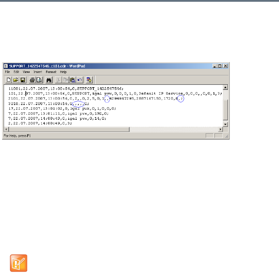
Appendix C - CDR Fields, Unformatted File
Polycom®, Inc. 915
Event Records
The event records, that is, all records in the unformatted file except the first record, contain standard fields,
such as the event type code and the time stamp, followed by fields that are event specific.
The event fields are separated by commas. Two consecutive commas with nothing between them (,,), or a
comma followed immediately by a semi-colon (,;), indicates an empty field, as in the example below:
Standard Event Record Fields
All event records start with the following fields:
●The CDR event type code. For a list of event type codes and descriptions, refer to .
●The event date.
●The event time.
●The structure length. This field is required for compatibility purposes, and always contains the value
0.
Event Types
The table below contains a list of the events that can be logged in the CDR file, and indicates where to find
details of the fields that are specific to that type of event.
The event code identifies the event in the unformatted CDR file, and the event name identifies the
event in the formatted CDR file.

Appendix C - CDR Fields, Unformatted File
Polycom®, Inc. 916
Event Specific Fields
CDR Event Types
Event Code Event Name Description
1 CONFERENCE
START
The conference started.
Note: There is one CONFERENCE START event per conference. It is always
the first event in the file, after the conference summary record. It contains
conference details, but not participant details.
2 CONFERENCE
END
The conference ended.
Note: There is one CONFERENCE END event per conference, and it is
always the last event in the file.
3 ISDN/PSTN
CHANNEL
CONNECTED
An ISDN/PSTN channel connected.
4 ISDN/PSTN
CHANNEL
DISCONNECTED
An ISDN/PSTN channel disconnected.
5 ISDN/PSTN
PARTICIPANT
CONNECTED
An ISDN/PSTN participant connected to the conference.
7 PARTICIPANT
DISCONNECTED
A participant disconnected from the conference.
10 DEFINED
PARTICIPANT
Information about a defined participant, that is, a participant who was added to
the conference before the conference started.
Note: There is one event for each participant defined before the conference
started.
15 H323 CALL
SETUP
Information about the IP address of the participant.
17 H323
PARTICIPANT
CONNECTED
An H.323 participant connected to the conference.
18 NEW
UNDEFINED
PARTICIPANT
A new undefined participant joined the conference.
20 BILLING CODE A billing code was entered by a participant using DTMF codes.
21 SET
PARTICIPANT
DISPLAY NAME
A user assigned a new name to a participant, or an end point sent its name.
22 DTMF CODE
FAILURE
An error occurred when a participant entered a DTMF code.

Appendix C - CDR Fields, Unformatted File
Polycom®, Inc. 917
23 SIP
PARTICIPANT
CONNECTED
A SIP participant connected to the conference.
26 RECORDING
LINK
A recording event, such as recording started or recording resumed, occurred.
28 SIP PRIVATE
EXTENSIONS
Contains SIP Private Extensions information.
30 GATEKEEPER
INFORMATION
Contains the gatekeeper caller ID, which makes it possible to match the CDR
in the gatekeeper and in the MCU.
31 PARTICIPANT
CONNECTION
RATE
Information about the line rate of the participant connection. This event is
added to the CDR file each time the endpoint changes its connection bit rate.
32 EVENT NEW
UNDEFINED
PARTY
CONTINUE IPV6
ADDRESS
Information about the IPv6 address of the participant’s endpoint.
33 PARTY CHAIR
UPDATE
Participants connect to the conferences as standard participants and they are
designated as chairpersons either by entering the chairperson password
during the IVR session upon connection, or while participating in the
conference using the appropriate DTM code.
34 PARTICIPANT
MAXIMUM
USAGE
INFORMATION
This event includes information of the maximum line rate, maximum resolution
and maximum frame rate used by H.323 or SIP participant during the
conference.
35 SVC SIP
PARTICIPANT
CONNECTED
An SVC user connected over SIP.
100 USER
TERMINATE
CONFERENCE
A user terminated the conference.
101 USER ADD
PARTICIPANT
A user added a participant to the conference during the conference.
102 USER DELETE
PARTICIPANT
A user deleted a participant from the conference.
103 USER
DISCONNECT
PARTICIPANT
A user disconnected a participant.
104 USER
RECONNECT
PARTICIPANT
A user reconnected a participant who was disconnected from the conference.
CDR Event Types
Event Code Event Name Description

Appendix C - CDR Fields, Unformatted File
Polycom®, Inc. 918
105 USER UPDATE
PARTICIPANT
A user updated the properties of a participant during the conference.
106 USER SET END
TIME
A user modified the conference end time.
107 OPERATOR
MOVE PARTY
FROM
CONFERENCE
The participant moved from an Entry Queue to the destination conference or
between conferences.
108 OPERATOR
MOVE PARTY
TO
CONFERENCE
The Collaboration Server User moved the participant from an ongoing
conference to another conference.
109 OPERATOR
ATTEND PARTY
The Collaboration Server User moved the participant to the Operator
conference.
111 OPERATOR
BACK TO
CONFERENCE
PARTY
The Collaboration Server User moved the participant back to his Home
(source) conference.
112 OPERATOR
ATTEND PARTY
TO
CONFERENCE
The Collaboration Server User moved the participant from the Operator
conference to another conference.
1001 NEW
UNDEFINED
PARTICIPANT
CONTINUE 1
Additional information about a NEW UNDEFINED PARTICIPANT event.
2001 CONFERENCE
START
CONTINUE 1
Additional information about a CONFERENCE START event.
2007 PARTICIPANT
DISCONNECTED
CONTINUE 1
Additional information about a PARTICIPANT DISCONNECTED event.
2010 DEFINED
PARTICIPANT
CONTINUE 1
Additional information about a DEFINED PARTICIPANT event.
2011 RESERVED
PARTICIPANT
CONTINUE PV6
ADDRESS
Additional information about a DEFINED PARTICIPANT event that includes
the IPv6 addressing of the defined participant.
2012 RESERVED
PARTICIPANT
CONTINUE 2
Additional information about a DEFINED PARTICIPANT event.
CDR Event Types
Event Code Event Name Description
Appendix C - CDR Fields, Unformatted File
Polycom®, Inc. 919
2101 USER ADD
PARTICIPANT
CONTINUE 1
Additional information about a USER ADD PARTICIPANT event.
2102 USER ADD
PARTICIPANT
CONTINUE 2
Additional information about a USER ADD PARTICIPANT event.
2105 USER UPDATE
PARTICIPANT
CONTINUE 1
Additional information about a USER UPDATE PARTICIPANT event.
2106 USER UPDATE
PARTICIPANT
CONTINUE 2
Additional information about a USER UPDATE PARTICIPANT event.
3010 PARTICIPANT
INFORMATION
The contents of the participant information fields.
5001 CONFERENCE
START
CONTINUE 4
Additional information about a CONFERENCE START event.
Note: An additional CONFERENCE START CONTINUE 4 event will be
written to the CDR each time the value of one of the following conference
fields is modified:
•Conference Password
•Chairperson Password
•Info1, Info2 or Info3
•Billing Info
These additional events will only contain the value of the modified field.
6001 CONFERENCE
START
CONTINUE 5
Additional information about a CONFERENCE START event.
11001 CONFERENCE
START
CONTINUE 10
Additional information about a CONFERENCE START event. This event
contains the Display Name.
CDR Event Types
Event Code Event Name Description

Appendix C - CDR Fields, Unformatted File
Polycom®, Inc. 920
Event Fields for Event 1 - CONFERENCE START
Field Description
Dial-Out Manually Indicates whether the conference was a dial-out manually conference or not.
Currently the only value is:
0 - The conference was not a dial-out manually conference, that is, the MCU initiates the
communication with dial-out participants, and the user does not need to connect them
manually.
Auto Terminate Indicates whether the conference was set to end automatically if no participant joins the
conference for a predefined time period after the conference starts, or if all participants
disconnect from the conference and the conference is empty for a predefined time period.
Possible values are:
0 - The conference was not set to end automatically.
1 - The conference was set to end automatically.
Line Rate The conference line rate, as follows:
0 - 64 kbps
6 - 384 kbps
12 - 1920 kbps
13 - 128 kbps
15 - 256 kbps
23 - 512 kbps
24 - 768 kbps
26 - 1152 kbps
29 - 1472 kbps
32 - 96 kbps
Line Rate (cont.) 33 - 1024 kbps
34 - 4096 kbps
Restrict Mode Not supported.
Always contains the value 0.
Audio Algorithm The audio algorithm.
Currently the only value is:
255 - Auto
Video Session The video session type.
Currently the only value is:
3 - Continuous Presence
Video Format The video format.
Currently the only value is:
255-Auto
CIF Frame Rate The CIF frame rate.
Currently the only value is:
255 -Auto

Appendix C - CDR Fields, Unformatted File
Polycom®, Inc. 921
QCIF Frame Rate The QCIF frame rate:
Currently the only value is:
255 -Auto
LSD Rate Not supported.
Always contains the value 0.
HSD Rate Not supported.
Always contains the value 0.
T120 Rate Not supported.
Always contains the value 0.
Event Fields for Event 2001 - CONFERENCE START CONTINUE 1
Field Description
Audio Tones Not supported.
Always contains the value 0.
Alert Tone Not supported.
Always contains the value 0.
Talk Hold Time The minimum time that a speaker has to speak to become the video source.
The value is in units of 0.01 seconds.
Currently the only value is 150, which indicates a talk hold time of 1.5 seconds.
Audio Mix Depth The maximum number of participants whose audio can be mixed.
Collaboration Servers 1500/2000/4000: 5
Soft MCUs and Collaboration Server 1800: AVC, 4; SVC, 5.
Operator
Conference
Not supported.
Always contains the value 0.
Video Protocol The video protocol.
Currently the only value is:
255 -Auto
Meet Me Per
Conference
Indicates the Meet Me Per Conference setting.
Currently the only value is:
1 - The Meet Me Per Conference option is enabled, and dial-in participants can join the
conference by dialing the dial-in number.
Number of Network
Services
Not supported.
Always contains the value 0.
Chairperson
Password
The chairperson password for the conference.
An empty field “” means that no chairperson password was assigned to the conference.
Event Fields for Event 1 - CONFERENCE START
Field Description

Appendix C - CDR Fields, Unformatted File
Polycom®, Inc. 922
Chair Mode Not supported.
Always contains the value 0.
Cascade Mode The cascading mode.
Currently the only value is:
0 - None
Master Name Not supported.
This field remains empty.
Minimum Number
of Participants
The number of participants for which the system reserved resources. Additional participants
may join the conference without prior reservation until all the resources are utilized.
Currently the only value is 0.
Allow Undefined
Participants
Indicates whether or not undefined dial-in participants can connect to the conference.
Currently the only value is:
1 - Undefined participants can connect to the conference
Time Before First
Participant Joins
Note: This field is only relevant if the Auto Terminate option is enabled.
Indicates the number of minutes that should elapse from the time the conference starts,
without any participant connecting to the conference, before the conference is automatically
terminated by the MCU.
Time After Last
Participant Quits
Note: This field is only relevant if the Auto Terminate option is enabled.
Indicates the number of minutes that should elapse after the last participant has
disconnected from the conference, before the conference is automatically terminated by the
MCU.
Conference Lock
Flag
Not supported.
Always contains the value 0.
Maximum Number
of Participants
The maximum number of participants that can connect to the conference at one time.
The value 65535 (auto) indicates that as many participants as the MCU’s resources allow
can connect to the conference, up to the maximum possible for the type of conference.
Audio Board ID Not supported.
Always contains the value 65535.
Audio Unit ID Not supported.
Always contains the value 65535.
Video Board ID Not supported.
Always contains the value 65535.
Video Unit ID Not supported.
Always contains the value 65535.
Data Board ID Not supported.
Always contains the value 65535.
Event Fields for Event 2001 - CONFERENCE START CONTINUE 1
Field Description

Appendix C - CDR Fields, Unformatted File
Polycom®, Inc. 923
Data Unit ID Not supported.
Always contains the value 65535.
Message Service
Type
The Message Service type.
Currently the only value is:
3 - IVR
Conference IVR
Service
The name of the IVR Service assigned to the conference.
Note: If the name of the IVR Service contains more than 20 characters, it will be truncated to
20 characters.
Lecture Mode Type Indicates the type of Lecture Mode, as follows:
0 - None
1 - Lecture Mode
3 - Presentation Mode
Lecturer Note: This field is only relevant if the Lecture Mode Type is Lecture Mode.
The name of the participant selected as the conference lecturer.
Time Interval Note: This field is only relevant if Lecturer View Switching is enabled.
The number of seconds a participant is to be displayed in the lecturer window before
switching to the next participant.
Currently the only value is 15.
Lecturer View
Switching
Note: This field is only relevant when Lecture Mode is enabled.
Indicates the lecturer view switching setting, as follows:
0 - Automatic switching between participants is disabled.
1 - Automatic switching between participants is enabled.
Audio Activated Not supported.
Always contains the value 0.
Lecturer ID Not supported.
Always contains the value 4294967295.
Event Fields for Event 5001 - CONFERENCE START CONTINUE 4
Field Description
Note: When this event occurs as the result of a change to the value of one of the event fields, the event will only
contain the value of the modified field. All other fields will be empty.
Conference ID The conference ID.
Conference Password The conference password.
An empty field “” means that no conference password was assigned to the conference.
Chairperson Password The chairperson password.
An empty field “” means that no chairperson password was assigned to the conference.
Event Fields for Event 2001 - CONFERENCE START CONTINUE 1
Field Description

Appendix C - CDR Fields, Unformatted File
Polycom®, Inc. 924
Info1
Info2
Info3
The contents of the conference information fields.
These fields enable users to enter general information for the conference, such as the
company name, and the contact person’s name and telephone number.
The maximum length of each field is 80 characters.
Billing Info The billing code.
Event Fields for Event 6001 - CONFERENCE START CONTINUE 5
Field Description
Encryption Indicates the conference encryption setting, as follows:
0 - The conference is not encrypted.
1 -The conference is encrypted.
Event Fields for Event 11001 - CONFERENCE START CONTINUE 10
Field Description
Display Name The Display Name of the conference.
Event Fields for Event 2 - CONFERENCE END
Field Description
Conference End
Cause
Indicates the reason for the termination of the conference, as follows:
1 - The conference is an ongoing conference or the conference was terminated by an MCU
reset.
2 - The conference was terminated by a user.
3 - The conference ended at the scheduled end time.
4 - The conference ended automatically because no participants joined the conference for a
predefined time period, or all the participants disconnected from the conference and the
conference was empty for a predefined time period.
5 - The conference never started.
6 - The conference could not start due to a problem.
8 - An unknown error occurred.
9 - The conference was terminated by a participant using DTMF codes.
Event Fields for Event 5001 - CONFERENCE START CONTINUE 4
Field Description

Appendix C - CDR Fields, Unformatted File
Polycom®, Inc. 925
Event fields for Event 3 - ISDN/PSTN CHANNEL CONNECTED
Field Description
Participant Name The name of the participant.
Participant ID The identification number assigned to the participant by the MCU.
Channel ID The channel identifier.
Number of
Channels
The number of channels being connected for this participant.
Connect Initiator Indicates who initiated the connection, as follows:
0 - Collaboration Server
1 - Participant
Any other number - Unknown
Call Type The call type, as follows:
68 - 56 KBS data call
72 - 1536kbs data call (PRI only)
75 - 56 KBS data call
77 - Modem data service
79 - 384kbs data call (PRI only)
86 - Normal voice call
Network Service
Program
The Network Service program, as follows:
0 - None
1 - ATT_SDN or NTI_PRIVATE
3 - ATT_MEGACOM or NTI_OUTWATS
4 - NTI FX
5 - NTI TIE TRUNK
6 - ATT ACCUNET
8 - ATT 1800
16 - NTI_TRO
Preferred Mode The value of the preferred/exclusive field for B channel selection (the PRF mode), as follows:
0 -None
1 -Preferred
2 -Exclusive
For more details refer to the Q.931 standard.
Calling Participant
Number Type
The type of calling number, as follows:
0 - Unknown, default
1 - International
2 - National
3 - Network specific
4 - Subscriber
6 - Abbreviated

Appendix C - CDR Fields, Unformatted File
Polycom®, Inc. 926
Calling Participant
Number Plan
The calling participant number plan.
0 - Unknown
1 - ISDN/PSTN
9 - Private
Calling Participant
Presentation
Indicator
The calling participant presentation indicator, as follows:
0 - Presentation allowed, default
1 - Presentation restricted
2 - Number not available
255 - Unknown
Calling Participant
Screening Indicator
The calling participant screening indicator, as follows:
0 - Participant not screened, default
1 - Participant verification succeeded
2 - Participant verification failed
3 - Network provided
255 - Unknown
Calling Participant
Phone Number
The telephone number used for dial-in.
Called Participant
Number Type
The type of number called, as follows:
0 - Unknown, default
1 - International
2 - National
3 - Network specific
4 - Subscriber
6 - Abbreviated
Called Participant
Number Plan
The called participant number plan, as follows:
0 - Unknown
1 - ISDN/PSTN
9 - Private
Called Participant
Phone Number
The telephone number used for dial-out.
Event fields for Event 4 - ISDN/PSTN CHANNEL DISCONNECTED
Field Description
Participant Name The participant name.
Participant ID The identification number assigned to the participant by the MCU.
Channel ID The channel identifier.
Event fields for Event 3 - ISDN/PSTN CHANNEL CONNECTED
Field Description

Appendix C - CDR Fields, Unformatted File
Polycom®, Inc. 927
Disconnect Initiator Indicates who initiated the disconnection, as follows:
0 - Collaboration Server
1 - Participant
Any other number - Unknown
Disconnect Coding
Standard
The disconnection cause code standard.
For values and explanations, see the Q.931 Standard.
Disconnect
Location
The disconnection cause location.
For values and explanations, see the Q.931 Standard.
Q931
Disconnection
Cause
The disconnection cause value.
For values and explanations, see the Q.931 Standard.
Event fields for Event 5 - ISDN/PSTN PARTICIPANT CONNECTED
Field Description
Participant Name The name of the participant.
Participant ID The identification number assigned to the participant by the MCU.
Participant Status The participant status, as follows:
0 -Idle
1 -Connected
2 - Disconnected
3 - Waiting for dial-in
4 -Connecting
5 - Disconnecting
6 - Partially connected. Party has completed H.221 capability exchange
7 - Deleted by a user
8 -Secondary. The participant could not connect the video channels and is connected via
audio only
10 - Connected with problem
11 - Redialing
Remote
Capabilities
Note: This field is only relevant to ISDN video participants.
The remote capabilities in H.221 format.
Remote
Communication
Mode
Note: This field is only relevant to ISDN video participants.
The remote communication mode in H.221 format.
Event fields for Event 4 - ISDN/PSTN CHANNEL DISCONNECTED
Field Description

Appendix C - CDR Fields, Unformatted File
Polycom®, Inc. 928
Secondary Cause Note: This field is only relevant to ISDN video participants and only if the Participant Status
is Secondary.
The cause for the secondary connection (not being able to connect the video channels), as
follows:
0 - Default
11 - The incoming video parameters are not compatible with the conference video
parameters
12 - H.323 card failure
13 - The conference video settings are not compatible with the endpoint capabilities
14 - The new conference settings are not compatible with the endpoint capabilities
Secondary Cause
(cont.)
15 - Video stream violation due to incompatible annexes or other discrepancy.
16 - Inadequate video resources
17 - When moved to a Transcoding or Video Switching conference, the participant’s video
capabilities are not supported by the video cards
18 - Video connection could not be established
24 - The endpoint closed its video channels
25 - The participant video settings are not compatible with the conference protocol
26 - The endpoint could not re-open the video channel after the conference video mode was
changed
27 - The gatekeeper approved a lower bandwidth than requested
28 - Video connection for the SIP participant is temporarily unavailable
29 - AVF problem. Insufficient bandwidth.
30 - H2.39 bandwidth mismatch
255 - Other
Event Fields for Event 7 - PARTICIPANT DISCONNECTED
Field Description
Participant Name The name of the participant.
Participant ID The identification number assigned to the participant by the MCU.
Call Disconnection
Cause
The disconnection cause. For more information about possible values, see .
Q931 Disconnect
Cause
If the disconnection cause is “No Network Connection” or “Participant Hang Up”, then this
field indicates the Q931 disconnect cause.
Event fields for Event 5 - ISDN/PSTN PARTICIPANT CONNECTED
Field Description

Appendix C - CDR Fields, Unformatted File
Polycom®, Inc. 929
Event Fields for Event 2007 - PARTICIPANT DISCONNECTED CONTINUE 1
Field Description
Rx Synchronization
Loss
The number of times that the general synchronization of the MCU was lost.
Tx Synchronization
Loss
The number of times that the general synchronization of the participant was lost.
Rx Video
Synchronization
Loss
The number of times that the synchronization of the MCU video unit was lost.
Tx Video
Synchronization
Loss
The number of times that the synchronization of the participant video was lost.
Mux Board ID Not supported.
Always contains the value 0.
Mux Unit ID Not supported.
Always contains the value 0.
Audio Codec Board
ID
Not supported.
Always contains the value 0.
Audio Codec Unit
ID
Not supported.
Always contains the value 0.
Audio Bridge Board
ID
Not supported.
Always contains the value 0.
Audio Bridge Unit
ID
Not supported.
Always contains the value 0.
Video Board ID Not supported.
Always contains the value 0.
Video Unit ID Not supported.
Always contains the value 0.
T.120 Board ID Not supported.
Always contains the value 0.
T.120 Unit ID Not supported.
Always contains the value 0.
T.120 MCS Board
ID
Not supported.
Always contains the value 0.
T.120 MCS Unit ID Not supported.
Always contains the value 0.

Appendix C - CDR Fields, Unformatted File
Polycom®, Inc. 930
H.323 Board ID Not supported.
Always contains the value 0.
H323 Unit ID Not supported.
Always contains the value 0.
Event Fields for Events 10, 101, 105 - DEFINED PARTICIPANT, USER ADD PARTICIPANT, USER UPDATE
PARTICIPANT
Field Description
User Name The login name of the user who added the participant to the conference, or updated the
participant properties.
Participant Name The name of the participant.
Participant ID The identification number assigned to the participant by the MCU.
Dialing Direction The dialing direction, as follows:
0 - Dial-out
5 - Dial-in
Bonding Mode Not supported.
Always contains the value 0.
Number Of
Channels
Note: This field is only relevant to ISDN/PSTN participants.
The number of channels being connected for this participant.
Net Channel Width Not supported.
Always contains the value 0.
Network Service
Name
The name of the Network Service.
An empty field “” indicates the default Network Service.
Restrict Not supported.
Always contains the value 0.
Audio Only Indicates the participant’s Audio Only setting, as follows:
0 - The participant is not an Audio Only participant
1 - The participant is an Audio Only participant
255 - Unknown
Event Fields for Event 2007 - PARTICIPANT DISCONNECTED CONTINUE 1
Field Description

Appendix C - CDR Fields, Unformatted File
Polycom®, Inc. 931
Default Number
Type
The type of telephone number, as follows:
0 - Unknown
1 - International
2 - National
3 - Network specific
4 - Subscriber
6 - Abbreviated
255 - Taken from Network Service, default
Notes:
•For dial-in participants, the only possible value is 255
•This field is only relevant to ISDN/PSTN participants.
Net Sub-Service
Name
Not supported.
This field remains empty.
Number of
Participant Phone
Numbers
The number of participant phone numbers.
n a dial-in connection, the participant phone number is the CLI (Calling Line Identification) as
identified by the MCU.
In a dial-out connection, participant phone numbers are the phone numbers dialed by the
MCU for each participant channel.
Note: This field is only relevant to ISDN/PSTN participants.
Number of MCU
Phone Numbers
The number of MCU phone numbers.
In a dial-in connection, the MCU phone number is the number dialed by the participant to
connect to the MCU.
In a dial-out connection, the MCU phone number is the MCU (CLI) number as seen by the
participant.
Note: This field is only relevant to ISDN/PSTN participants.
Party and MCU
Phone Numbers
No, one or more fields, one field for each participant and MCU phone number.
The participant phone numbers are listed first, followed by the MCU phone numbers.
Note: This field is only relevant to ISDN/PSTN participants.
Identification
Method
The method by which the destination conference is identified, as follows:
1 - Called phone number, IP address or alias
2 - Calling phone number, IP address or alias
Note: This field is only relevant to dial-in participants.
Meet Me Method The meet-me per method. Currently the only value is:
3 - Meet-me per participant
Note: This field is only relevant to dial-in participants.
Event Fields for Events 10, 101, 105 - DEFINED PARTICIPANT, USER ADD PARTICIPANT, USER UPDATE
PARTICIPANT
Field Description

Appendix C - CDR Fields, Unformatted File
Polycom®, Inc. 932
Event Fields for Events 2010, 2011, 2015 - DEFINED PARTICIPANT CONTINUE 1,USER ADD PARTICIPANT
CONTINUE 1, USER UPDATE PARTICIPANT CONTINUE 1
Field Description
Network Type The type of network between the participant and the MCU, as follows:
0 - ISDN/PSTN
2 - H.323
5 - SIP
H.243 Password Not supported.
This field remains empty.
Chair Not supported.
Always contains the value 0.
Video Protocol The video protocol used by the participant, as follows:
1 - H.261
2 - H.263
4 - H.264
255 - Auto
Broadcasting
Volume
The broadcasting volume assigned to the participant.
The value is between 1 (lowest) and 10 (loudest).
Each unit movement increases or decreases the volume by 3 dB.
Undefined
Participant
Indicates whether are not the participant is an undefined participant, as follows:
0 - The participant is not an undefined participant.
2 - The participant is an undefined participant.
Node Type The node type, as follows:
0 - MCU
1 - Terminal
Bonding Phone
Number
The phone number for Bonding dial-out calls.
Bonding is a communication protocol that aggregates from two up to thirty 64 Kbps B
channels together, to look like one large bandwidth channel.
Note: This field is only relevant to ISDN/PSTN participants.
Video Bit Rate The video bit rate in units of kilobits per second.
A value of 4294967295 denotes auto, and in this case, the rate is computed by the MCU.
IP Address Note: This field is only relevant to IP participants.
The IP address of the participant.
An address of 4294967295 indicates that no IP address was specified for the participant, and
the gatekeeper is used for routing. In all other cases the address overrides the gatekeeper.
Signaling Port Note: This field is only relevant to IP participants.
The signaling port used for participant connection.

Appendix C - CDR Fields, Unformatted File
Polycom®, Inc. 933
H.323 Participant
Alias Type/SIP
Participant Address
Type
Note: This field is only relevant to IP participants.
For H.323 participants, the alias type, as follows:
7 - E164
8 - H.323 ID
13 - Email ID
14 - Participant number
For SIP participants, the address type, as follows:
1 - SIP URI
2 - Tel URL
H.323 Participant
Alias Name/SIP
Participant Address
Note: This field is only relevant to IP participants.
For H.323 participants:
The participant alias. May contain up to 512 characters.
For SIP participants:
The participant address. May contain up to 80 characters.
Event Fields for Event 2011 - DEFINED PARTICIPANT CONTINUE 2, Event 2012 - USER ADD PARTICIPANT
CONTINUE 2, Event 2016 - USER UPDATE PARTICIPANT CONTINUE 2
Field Description
Encryption Indicates the participant’s encryption setting as follows:
0 - The participant is not encrypted.
1 - The participant is encrypted.
2 - Auto. The conference encryption setting is applied to the participant.
Participant Name The name of the participant.
Participant ID The identification number assigned to the participant by the MCU.
Event fields for Event 15 - H323 CALL SETUP
Field Description
Participant Name The name of the participant.
Participant ID The identification number assigned to the participant by the MCU.
Connect Initiator Indicates who initiated the connection, as follows:
0 - MCU
1 - Remote participant
Any other number - Unknown
Event Fields for Events 2010, 2011, 2015 - DEFINED PARTICIPANT CONTINUE 1,USER ADD PARTICIPANT
CONTINUE 1, USER UPDATE PARTICIPANT CONTINUE 1
Field Description

Appendix C - CDR Fields, Unformatted File
Polycom®, Inc. 934
Min Rate The minimum line rate used by the participant.
The data in this field should be ignored. For accurate rate information, see CDR event 31.
Max Rate The maximum line rate achieved by the participant.
The data in this field should be ignored. For accurate rate information, see CDR event 31.
Source Party
Address
The IP address of the calling participant.
A string of up to 255 characters.
Destination Party
Address
The IP address of the called participant.
A string of up to 255 characters.
Endpoint Type The endpoint type, as follows:
0 - Terminal
1 - Gateway
2 - MCU
3 - Gatekeeper
4 - Undefined
Event Fields for Events 17, 23 - H323 PARTICIPANT CONNECTED, SIP PARTICIPANT CONNECTED
Field Description
Participant Name The name of the participant.
An empty field “” denotes an unidentified participant or a participant whose name is
unspecified.
Participant ID The identification number assigned to the participant by the MCU.
Participant Status The participant status, as follows:
0 -Idle
1 -Connected
2 - Disconnected
3 - Waiting for dial-in
4 – Connecting
5 - Disconnecting
6 - Partially connected. Party has completed H.221 capability exchange
7 - Deleted by a user
8 -Secondary. The participant could not connect the video channels and is connected via
audio only
10 - Connected with problem
11 - Redialing
Capabilities Not supported.
Always contains the value 0.
Event fields for Event 15 - H323 CALL SETUP
Field Description

Appendix C - CDR Fields, Unformatted File
Polycom®, Inc. 935
Remote
Communication
Mode
Not supported.
Always contains the value 0.
Secondary Cause Note: This field is only relevant if the Participant Status is Secondary.
The cause for the secondary connection (not being able to connect the video channels), as
follows:
0 - Default
11 - The incoming video parameters are not compatible with the conference video
parameters
13 - The conference video settings are not compatible with the endpoint capabilities
14 - The new conference settings are not compatible with the endpoint capabilities
15 - Video stream violation due to incompatible annexes or other discrepancy
16 - Inadequate video resources
17 - When moved to a Transcoding or Video Switching conference, the participant’s video
capabilities are not supported by the video cards
18 - Video connection could not be established
24 - The endpoint closed its video channels
25 - The participant video settings are not compatible with the conference protocol
26 - The endpoint could not re-open the video channel after the conference video mode was
changed
27 - The gatekeeper approved a lower bandwidth than requested
28 - Video connection for the SIP participant is temporarily unavailable
255 - Other
Event Fields for Event 18 - NEW UNDEFINED PARTICIPANT
Field Description
Participant Name The name of the participant.
Participant ID The identification number assigned to the participant by the MCU.
Dialing Direction The dialing direction, as follows
0 - Dial-out
5 - Dial-in
Bonding Mode Not supported.
Always contains the value 0.
Number of
Channels
The number of channels being connected for this participant.
Note: This field is only relevant to ISDN/PSTN participants.
Net Channel Width Not supported.
Always contains the value 0.
Event Fields for Events 17, 23 - H323 PARTICIPANT CONNECTED, SIP PARTICIPANT CONNECTED
Field Description

Appendix C - CDR Fields, Unformatted File
Polycom®, Inc. 936
Network Service
Name
The name of the Network Service.
An empty field “” indicates the default Network Service.
Restrict Not supported.
Always contains the value 0.
Audio Only Indicates the participant’s Audio Only setting, as follows:
0 - The participant is not an Audio Only participant
1 - The participant is an Audio Only participant
255 - Unknown
Default Number
Type
The type of telephone number.
Note: Since undefined participants are always dial-in participants, the only possible value is:
255 - Taken from Network Service
Note: This field is only relevant to ISDN/PSTN participants.
Net Sub-Service
Name
Not supported.
This field remains empty.
Number of
Participant Phone
Numbers
The number of participant phone numbers.
The participant phone number is the CLI (Calling Line Identification) as identified by the
MCU.
Note: This field is only relevant to ISDN/PSTN participants.
Number of MCU
Phone Numbers
The number of MCU phone numbers.
The MCU phone number is the number dialed by the participant to connect to the MCU.
Note: This field is only relevant to ISDN/PSTN participants.
Party and MCU
Phone Numbers
No, one or more fields, one field for each participant and MCU phone number.
The participant phone numbers are listed first, followed by the MCU phone numbers.
Note: This field is only relevant to ISDN/PSTN participants.
Identification
Method
Note: This field is only relevant to dial-in participants.
The method by which the destination conference is identified, as follows:
1 - Called phone number, IP address or alias
2 - Calling phone number, IP address or alias
Meet Me Method Note: This field is only relevant to dial-in participants.
The meet-me per method, as follows:
3 - Meet-me per participant
Network Type The type of network between the participant and the MCU, as follows:
0 - ISDN/PSTN
2 - H.323
5 - SIP
H.243 Password Not supported.
This field remains empty.
Event Fields for Event 18 - NEW UNDEFINED PARTICIPANT
Field Description

Appendix C - CDR Fields, Unformatted File
Polycom®, Inc. 937
Chair Not supported.
Always contains the value 0.
Video Protocol The video protocol, as follows:
1 - H.261
2 - H.263
4 - H.264
255 -Auto
Broadcasting
Volume
The broadcasting volume assigned to the participant.
The value is between 1 (lowest) and 10 (loudest).
Each unit movement increases or decreases the volume by 3 dB.
Undefined
Participant
Indicates whether are not the participant is an undefined participant, as follows:
0 - The participant is not an undefined participant.
2 - The participant is an undefined participant.
Node Type The node type, as follows:
0 - MCU
1 - Terminal
Bonding Phone
Number
Note: This field is only relevant to ISDN/PSTN participants.
The phone number for Bonding dial-out calls.
Bonding is a communication protocol that aggregates from two up to thirty 64 Kbps B
channels together, to look like one large bandwidth channel.
Video Bit Rate The video bit rate in units of kilobits per second.
A value of 4294967295 denotes auto, and in this case, the rate is computed by the MCU.
IP Address Note: This field is only relevant to IP participants.
The IP address of the participant.
An address of 4294967295 indicates that no IP address was specified for the participant, and
the gatekeeper is used for routing. In all other cases the address overrides the gatekeeper.
Signaling Port Note: This field is only relevant to IP participants.
The signaling port used for participant connection.
A value of 65535 is ignored by MCU.
H.323 Participant
Alias Type/SIP
Participant Address
Type
Note: This field is only relevant to IP participants.
For H.323 participants, the alias type, as follows:
7 - E164
8 - H.323 ID
13 - Email ID
14 - Participant number
For SIP participants, the address type, as follows:
1 - SIP URI
2 - Tel URL
Event Fields for Event 18 - NEW UNDEFINED PARTICIPANT
Field Description

Appendix C - CDR Fields, Unformatted File
Polycom®, Inc. 938
H.323 Participant
Alias Name/SIP
Participant Address
Note: This field is only relevant to IP participants.
For H.323 participants:
The participant alias. May contain up to 512 characters.
For SIP participants:
The participant address. May contain up to 80 characters.
Event Fields for Event 1001 - NEW UNDEFINED PARTY CONTINUE 1
Field Description
Encryption Indicates the participant’s encryption setting as follows:
0 - The participant is not encrypted.
1 - The participant is encrypted.
2 - Auto. The conference encryption setting is applied to the participant.
Participant Name The name of the participant.
Participant ID The identification number assigned to the participant by the MCU.
Event Fields for Event 20 - BILLING CODE
Field Description
Participant Name The name of the participant who added the billing code.
Participant ID The identification number, as assigned by the MCU, of the participant who added the billing
code.
Billing Info The numeric billing code that was added (32 characters).
Event Fields for Event 21 - SET PARTICIPANT DISPLAY NAME
Field Description
Participant Name The original name of the participant, for example, the name automatically assigned to an
undefined participant, such as, “<conference name>_(000)”.
Participant ID The identification number assigned to the participant by the MCU.
Display Name The new name assigned to the participant by the user, or the name sent by the end point.
Event Fields for Event 18 - NEW UNDEFINED PARTICIPANT
Field Description

Appendix C - CDR Fields, Unformatted File
Polycom®, Inc. 939
Event Fields for Event 22 - DTMF CODE FAILURE
Field Description
Participant Name The name of the participant.
Participant ID The identification number assigned to the participant by the MCU.
Incorrect Data The incorrect DTMF code entered by the participant, or an empty field “” if the participant did
not press any key.
Correct Data The correct DTMF code, if known.
Failure Type The type of DTMF failure, as follows:
2 - The participant did not enter the correct conference password.
6 - The participant did not enter the correct chairperson password.
12 - The participant did not enter the correct Conference ID.
Event fields for Event 26 - RECORDING LINK
Field Description
Participant Name The name of the Recording Link participant.
Participant ID The identification number assigned to the Recording Link participant by the MCU.
Recording
Operation
The type of recording operation, as follows:
0 - Start recording
1 - Stop recording
2 - Pause recording
3 - Resume recording
4 - Recording ended
5 - Recording failed
Initiator Not supported.
Recording Link
Name
The name of the Recording Link.
Recording Link ID The Recording Link ID.
Start Recording
Policy
The start recording policy, as follows:
1 - Start recording automatically as soon as the first participant connects to the conference.
2 - Start recording when requested by the conference chairperson via DTMF codes or from
the Collaboration Server Web Client, or when the operator starts recording from the
Collaboration Server Web Client.

Appendix C - CDR Fields, Unformatted File
Polycom®, Inc. 940
Event Fields for Event 28 - SIP PRIVATE EXTENSIONS
Field Description
Participant Name The name of the participant.
Participant ID The participant’s identification number as assigned by the system.
Called Participant
ID
The called participant ID.
Asserted Identity The identity of the user sending a SIP message as it was verified by authentication.
Charging Vector A collection of charging information.
Preferred Identity The identity the user sending the SIP message wishes to be used for the P-Asserted-Header
field that the trusted element will insert.
Event Fields for Event 30 - GATEKEEPER INFORMATION
Field Description
Participant Name The name of the participant.
Participant ID The identification number assigned to the participant by the MCU.
Gatekeeper Caller
ID
The caller ID in the gatekeeper records. This value makes it possible to match the CDR in
the gatekeeper and in the MCU.
Event fields for Event 31 - PARTICIPANT CONNECTION RATE
Field Description
Participant Name The participant name.
Participant ID The identification number assigned to the participant by the MCU.
Participant Current
Rate
The participant line rate in Kbps.
Event Fields for Event 32
Field Description
IP V6 IPv6 address of the participant’s endpoint.

Appendix C - CDR Fields, Unformatted File
Polycom®, Inc. 941
Event fields for Event 33 - PARTY CHAIR UPDATE
Field Description
Participant Name The participant name.
Participant ID The identification number assigned to the participant by the MCU.
Chairperson Possible values:
•True - participant is a chairperson
•False - Participant is not a chairperson participant (is a standard participant)
Event fields for Event 34 - PARTICIPANT MAXIMUM USAGE INFORMATION
Field Description
Participant Name The name of the participant.
Participant ID The identification number assigned to the participant by the MCU.
Maximum Bit Rate The maximum bit rate used by the participant during the call.
Maximum Resolution The maximum resolution used by the participant during the call.
Note: The reported resolutions are: CIF, SD, HD720, and HD1080. Other resolutions are
rounded up to the nearest resolution. For example, 2SIF is reported as SD resolution.
Maximum Frame Rate The maximum frame rate used by the participant during the call.
Participant Address Note: This field is only relevant to IP participants.
For H.323 participants, the participant alias. The alias may contain up to 512 characters.
For SIP participants, the participant address. The address may contain up to 80
characters.
Event Fields for Event 35 - SVC SIP PARTICIPANT CONNECTED
Field Description
Participant Name The name of the participant.
An empty field "" denotes an unidentified participant or a participant whose name is
unspecified
Participant ID The identification number assigned to the participant by the MCU.

Appendix C - CDR Fields, Unformatted File
Polycom®, Inc. 942
Participant Status The participant status, as follows:
0 - Idle
1 - Connected
2 - Disconnected
3 - Waiting for dial-in
4 - Connecting
5 - Disconnecting
6 - Partially connected. Party has completed H.221 capability exchange
7 - Deleted by a user
8 - Secondary. The participant could not connect the video channels and is connected via
audio only
10 - Connected with problem
11 - Redialing
Receive line rate Negotiated reception line rate
Transmit line rate Negotiated transmission line rate
Uplink Video
Capabilities
•Number of uplink streams
•Video stream (multiple streams):
Resolution width
resolution height
max frame rate
max line rate
Audio Codec SAC, Other
Secondary Cause
Event Fields for Event 100 - USER TERMINATE CONFERENCE
Field Description
Terminated By The login name of the user who terminated the conference.
Event Fields for Events 102,103, 104 - USER DELETE PARTICIPANT, USER DISCONNECT PARTICIPANT, USER
RECONNECT PARTICIPANT
Field Description
User Name The login name of the user who reconnected the participant to the conference, or
disconnected or deleted the participant from the conference.
Event Fields for Event 35 - SVC SIP PARTICIPANT CONNECTED
Field Description

Appendix C - CDR Fields, Unformatted File
Polycom®, Inc. 943
Participant Name The name of the participant reconnected to the conference, or disconnected or deleted from
the conference.
Participant ID The identification number assigned to the participant by the MCU.
Event Fields for Event 106 - USER SET END TIME
Field Description
New End Time The new conference end time set by the user, in GMT.
User Name The login name of the user who changed the conference end time.
Event Fields for Events 107 and 109 - OPERATOR MOVE PARTY FROM CONFERENCE and OPERATOR
ATTEND PARTY
Field Description
Operator Name The login name of the user who moved the participant.
Party Name The name of the participant who was moved.
Party ID The identification number of the participant who was moved, as assigned by the MCU.
Destination Conf
Name
The name of the conference to which the participant was moved.
Destination Conf ID The identification number of the conference to which the participant was moved.
Event Fields for Events 108, 112 - OPERATOR MOVE PARTY TO CONFERENCE,OPERATOR ATTEND PARTY
TO CONFERENCE
Field Description
Operator Name The login name of the operator who moved the participant to the conference.
Source Conf Name The name of the source conference.
Source Conf ID The identification number of the source conference, as assigned by the MCU.
Party Name The name of the participant who was moved.
Party ID The identification number assigned to the participant by the MCU.
Connection Type The connection type, as follows:
0 - Dial-out
5 - Dial-in
Event Fields for Events 102,103, 104 - USER DELETE PARTICIPANT, USER DISCONNECT PARTICIPANT, USER
RECONNECT PARTICIPANT
Field Description

Appendix C - CDR Fields, Unformatted File
Polycom®, Inc. 944
Bonding Mode Possible values are:
0 - Bonding is disabled
1 - Bonding is enabled
255 -Auto
Note: This field is only relevant to ISDN/PSTN participants.
Number Of
Channels
The number of channels, as follows:
255 - Auto
Otherwise, in range of 1 - 30
Note: This field is only relevant to ISDN/PSTN participants.
Net Channel Width The bandwidth of each channel.
This value is always 0, which represents a bandwidth of 1B, which is the only bandwidth that
is currently supported.
Net Service Name The name of the Network Service.
An empty field “” indicates the default Network Service.
Restrict Indicates whether or not the line is restricted, as follows:
27 - Restricted line
28 - Non restricted line
255 - Unknown or not relevant
Voice Mode Indicates whether or not the participant is an Audio Only participant, as follows:
0 - The participant is not an Audio Only participant
1 - The participant is an Audio Only participant
255 - Unknown
Number Type The type of telephone number, as follows:
0 - Unknown
1 - International
2 - National
3 - Network specific
4 - Subscriber
6 - Abbreviated
255 - Taken from Network Service, default
Note: This field is only relevant to dial-out, ISDN/PSTN participants.
Net SubService
Name
The network sub-service name.
An empty field “” means that MCU selects the default sub-service.
Note: This field is only relevant to dial-out, ISDN/PSTN participants.
Event Fields for Events 108, 112 - OPERATOR MOVE PARTY TO CONFERENCE,OPERATOR ATTEND PARTY
TO CONFERENCE
Field Description

Appendix C - CDR Fields, Unformatted File
Polycom®, Inc. 945
Number of Party
Phone Numbers
The number of participant phone numbers.
In a dial-in connection, the participant phone number is the CLI (Calling Line Identification)
as identified by the MCU.
In a dial-out connection, participant phone numbers are the phone numbers dialed by the
MCU for each participant channel.
Note: This field is only relevant to ISDN/PSTN participants.
Number of MCU
Phone Numbers
The number of MCU phone numbers.
In a dial-in connection, the MCU phone number is the number dialed by the participant to
connect to the MCU.
In a dial-out connection, the MCU phone number is the MCU (CLI) number as seen by the
participant.
Note: This field is only relevant to ISDN/PSTN participants.
Party and MCU
Phone Numbers
The participant phone numbers are listed first, followed by the MCU phone numbers.
Note: This field is only relevant to ISDN/PSTN participants.
Ident. Method Note: This field is only relevant to dial-in participants.
The method by which the destination conference is identified, as follows:
0 - Password
1 - Called phone number, or IP address, or alias
2 - Calling phone number, or IP address, or alias
Meet Method Note: This field is only relevant to dial-in participants.
The meet-me per method, as follows:
1 - Meet-me per MCU-Conference
3 - Meet-me per participant
4 - Meet-me per channel
Net Interface Type The type of network interface between the participant and the MCU, as follows:
0 - ISDN
2 - H.323
5 - SIP
H243 Password The H.243 password, or an empty field “” if there is no password.
Chair Not supported.
Always contains the value 0.
Video Protocol The video protocol, as follows:
1 - H.261
2 - H.263
3 - H.264*
4 - H.264
255 -Auto
Event Fields for Events 108, 112 - OPERATOR MOVE PARTY TO CONFERENCE,OPERATOR ATTEND PARTY
TO CONFERENCE
Field Description

Appendix C - CDR Fields, Unformatted File
Polycom®, Inc. 946
Audio Volume The broadcasting volume assigned to the participant.
The value is between 1 (lowest) and 10 (loudest).
Undefined Type The participant type, as follows:
0 - Defined participant. (The value in the formatted text file is “default”.)
2 - Undefined participant. (The value in the formatted text file is “Unreserved participant “.)
Node Type The node type, as follows:
0 - MCU
1 - Terminal
Bonding Phone
Number
Note: This field is only relevant to ISDN/PSTN participants.
The phone number for Bonding dial-out calls.
Video Rate Note: This field is only relevant to IP participants.
The video rate in units of kilobits per second.
A value of 4294967295 denotes auto, and in this case, the rate is computed by the MCU.
IP Address Note: This field is only relevant to IP participants.
The IP address of the participant.
An address of 4294967295 indicates that no IP address was specified for the participant,
and the gatekeeper is used for routing. In all other cases the address overrides the
gatekeeper.
Call Signaling Port Note: This field is only relevant to IP participants.
The signaling port used for participant connection.
A value of 65535 is ignored by MCU.
H.323 Party Alias
Type/SIP Party
Address Type
Note: This field is only relevant to IP participants.
For H.323 participants, the alias type, as follows:
7 - E164
8 - H.323 ID
11 - URL ID alias type
12 - Transport ID
13 - Email ID
14 - Participant number
For SIP participants, the address type, as follows:
1 - SIP URI
2 - Tel URL
H.323 Party
Alias/SIP Party
Address
Note: This field is only relevant to IP participants.
For H.323 participants, the participant alias. The alias may contain up to 512 characters.
For SIP participants, the participant address. The address may contain up to 80 characters.
Event Fields for Events 108, 112 - OPERATOR MOVE PARTY TO CONFERENCE,OPERATOR ATTEND PARTY
TO CONFERENCE
Field Description

Appendix C - CDR Fields, Unformatted File
Polycom®, Inc. 947
Disconnection Cause Values
Event Fields for Event 111 - OPERATOR BACK TO CONFERENCE PARTY
Field Description
Operator Name The login name of the operator moving the participant back to the conference.
Party Name The name of the participant being moved.
Party ID The identification number, as assigned by the MCU, of the participant being moved.
Event Fields for Events 2011, 2012, and 2016
Field Description
IP V6 IPv6 address of the participant’s endpoint.
Event Fields for Event 3010 - PARTICIPANT INFORMATION
Field Description
Info1
Info2
Info3
Info4
The participant information fields.
These fields enable users to enter general information about the participant, such as the
participant’s e-mail address.
The maximum length of each field is 80 characters.
VIP Not supported.
Always contains the value 0.
For an explanation of the disconnection causes, see Appendix A - Disconnection Causes.
Disconnection Cause Values
Value Call Disconnection Cause
0 Unknown
1 Participant hung up
2 Disconnected by User
5 Resources deficiency
6 Password failure

Appendix C - CDR Fields, Unformatted File
Polycom®, Inc. 948
20 H323 call close. No port left for audio
21 H323 call close. No port left for video
22 H323 call close. No port left for FECC
23 H323 call close. No control port left
25 H323 call close. No port left for video content
51 A common key exchange algorithm could not be established between the MCU and the remote device
53 Remote device did not open the encryption signaling channel
59 The remote devices’ selected encryption algorithm does not match the local selected encryption algorithm
141 Called party not registered
145 Caller not registered
152 H323 call close. ARQ timeout
153 H323 call close. DRQ timeout
154 H323 call close. Alt Gatekeeper failure
191 H323 call close. Remote busy
192 H323 call close. Normal
193 H323 call close. Remote reject
194 H323 call close. Remote unreachable
195 H323 call close. Unknown reason
198 H323 call close. Small bandwidth
199 H323 call close. Gatekeeper failure
200 H323 call close. Gatekeeper reject ARQ
201 H323 call close. No port left
202 H323 call close. Gatekeeper DRQ
203 H323 call close. No destination IP value
204 H323 call close. Remote has not sent capability
205 H323 call close. Audio channels not open
207 H323 call close. Bad remote cap
208 H323 call close. Capabilities not accepted by remote
209 H323 failure
Disconnection Cause Values
Value Call Disconnection Cause

Appendix C - CDR Fields, Unformatted File
Polycom®, Inc. 949
210 H323 call close. Remote stop responding
213 H323 call close. Master slave problem
251 SIP timer popped out
252 SIP card rejected channels
253 SIP capabilities don’t match
254 SIP remote closed call
255 SIP remote cancelled call
256 SIP bad status
257 SIP remote stopped responding
258 SIP remote unreachable
259 SIP transport error
260 SIP bad name
261 SIP trans error TCP invite
300 SIP redirection 300
301 SIP moved permanently
302 SIP moved temporarily
305 SIP redirection 305
380 SIP redirection 380
400 SIP client error 400
401 SIP unauthorized
402 SIP client error 402
403 SIP forbidden
404 SIP not found
405 SIP client error 405
406 SIP client error 406
407 SIP client error 407
408 SIP request timeout
409 SIP client error 409
410 SIP gone
Disconnection Cause Values
Value Call Disconnection Cause

Appendix C - CDR Fields, Unformatted File
Polycom®, Inc. 950
411 SIP client error 411
413 SIP client error 413
414 SIP client error 414
415 SIP unsupported media type
420 SIP client error 420
480 SIP temporarily not available
481 SIP client error 481
482 SIP client error 482
483 SIP client error 483
484 SIP client error 484
485 SIP client error 485
486 SIP busy here
487 SIP request terminated
488 SIP client error 488
500 SIP server error 500
501 SIP server error 501
502 SIP server error 502
503 SIP server error 503
504 SIP server error 504
505 SIP server error 505
600 SIP busy everywhere
603 SIP global failure 603
604 SIP global failure 604
606 SIP global failure 606
Disconnection Cause Values
Value Call Disconnection Cause

Polycom®, Inc. 951
Appendix D - Ad Hoc Conferencing and
External Database Authentication
The RealPresence Collaboration Server (RMX) 1500/1800/2000/4000 Ad Hoc conferencing feature
enables participants to start ongoing conferences on-the-fly, without prior definition when dialing an Ad
Hoc-enabled Entry Queue. The created conference parameters are taken from the Profile assigned to the
Ad Hoc-enabled Entry Queue.
Ad Hoc conferencing is available in two the following modes:
●Ad Hoc Conferencing without Authentication
Any participant can dial into an Entry Queue and initiate a new conference if the conference does not
exist. This mode is usually used for the organization’s internal Ad Hoc conferencing.
●Ad Hoc Conferencing with External Database Authentication
In this mode, the participant’s right to start a new conference is validated against a database.
The external database application can also be used to validate the participant’s right to join an ongoing
conference. Conference access authentication can be:
●Part of the Ad Hoc conferencing flow where the participants must be authorized before they can enter
the conference created in the Ad Hoc flow.
●Independent of Ad Hoc conferencing where conference access is validated for all conferences
running on the MCU regardless of the method in which the conference was started.
Ad Hoc Conferencing without Authentication
A participant dials in to an Ad Hoc-enabled Entry Queue and starts a new conference based on the Profile
assigned to the Entry Queue. In this configuration, any participant connecting to the Entry Queue can start
a new conference, and no security mechanism is applied. This mode is usually used in organizations where
Ad Hoc conferences are started from within the network and without security breach.
A conference is started using one of the following method:
1The participant dials in to the Ad Hoc-enabled Entry Queue.
2The Conference ID is requested by the system.
3The participant inputs a Conference ID via his/her endpoint remote control using DTMF codes.
4The MCU checks whether a conference with the same Conference ID is running on the MCU. If
there is such a conference, the participant is moved to that conference. If there is no ongoing
conference with that Conference ID, the system creates a new conference, based on the Profile
assigned to the Entry Queue, and connects this participant as the conference chairperson.
External Database Authentication is not supported in the RealPresence Collaboration Server 1800.
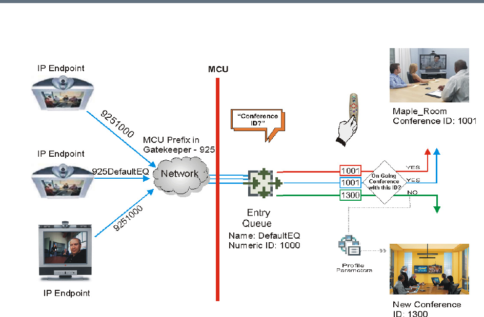
Appendix D - Ad Hoc Conferencing and External Database Authentication
Polycom®, Inc. 952
Ad Hoc Conference Initiation without Authentication
To enable this workflow, the following components must be defined in the system:
●An Entry Queue IVR Service with the appropriate audio file requesting the Conference ID
●An Ad Hoc-enabled Entry Queue with an assigned Profile
Ad Hoc Conferencing with Authentication
The MCU can work with an external database application to validate the participant’s right to start a new
conference. The external database contains a list of participants, with their assigned parameters. The
conference ID entered by the participant is compared against the database. If the system finds a match, the
participant is granted the permission to start a new conference.
To work with an external database application to validate the participant’s right to start a new conference,
the Entry Queue IVR Service must be configured to use the external database application for authentication.
In the external database application, you must define all participants (users) with rights to start a new
conference using Ad Hoc conferencing. For each user defined in the database, you enter the conference
ID, Conference Password (optional) and Chairperson Password (when applicable), billing code, Conference
general information (corresponding to the User Defined 1 field in the Profile properties) and user’s PIN code.
The same user definitions can be used for conference access authentication, that is, to determine who can
join the conference as a participant and who as a chairperson.
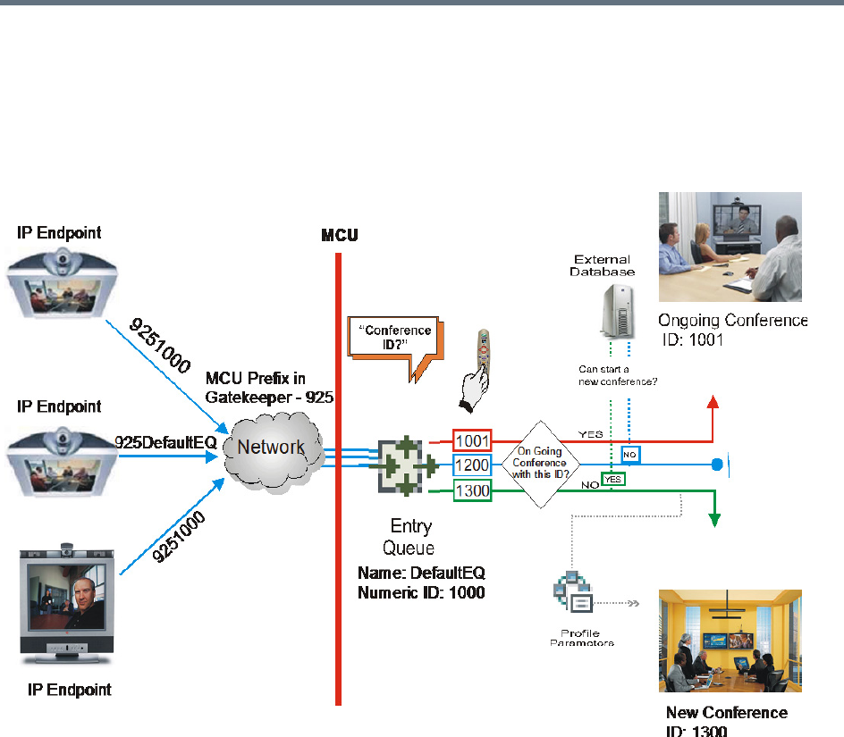
Appendix D - Ad Hoc Conferencing and External Database Authentication
Polycom®, Inc. 953
Entry Queue Level - Conference Initiation Validation with an External
Database Application
Starting a new conference with external database application validation entails the following steps:
Conference Initiation Validation with External Database Application
●The participant dials in to an Ad Hoc-enabled Entry Queue.
●The participant is requested to enter the Conference ID.
●The participant enters the conference ID via his/her endpoint remote control using DTMF codes. If
there is an ongoing conference with this Conference ID, the participant is moved to that conference
where another authentication process can occur, depending on the IVR Service configuration.
●If there is no ongoing conference with that Conference ID, the MCU verifies the Conference ID with
the database application that compares it against its database. If the database application finds a
match, the external database application sends a response back to the MCU, granting the participant
the right to start a new ongoing conference.
●If this Conference ID is not registered in the database, the conference cannot be started and this
participant is disconnected from the Entry Queue.
●The external database contains a list of participants (users), with their assigned parameters. Once a
participant is identified in the database (according to the conference ID), his/her parameters (as
defined in the database) can be sent to the MCU in the same response granting the participant the
right to start a new ongoing conference. These parameters are:

Appendix D - Ad Hoc Conferencing and External Database Authentication
Polycom®, Inc. 954
Conference Name
Conference Billing code
Conference Password
Chairperson Password
Conference Information, such as the contact person name. These fields correspond to Info 1, 2
and 3 fields in the Conference Properties - Information dialog box.
Maximum number of participants allowed for the conference
Conference Owner
These parameters can also be defined in the conference Profile. In such a case, parameters sent
from the database overwrite the parameters defined in the Profile. If these parameters are not sent
from the external database to the MCU, they will be taken from the Profile.
1A new conference is started based on the Profile assigned to the Entry Queue.
2The participant is moved to the conference.
If no password request is configured in the Conference IVR Service assigned to the conference, the
participant that initiated the conference is directly connected to the conference, as its chairperson.
If the Conference IVR Service assigned to the conference is configured to prompt for the conference
password and chairperson password, without external database authentication, the participant has
to enter these passwords in order to join the conference.
To enable this workflow, the following components must be defined in the system:
●A Conference IVR Service with the appropriate prompts. If conference access is also validated with
the external database application it must be configured to access the external database for
authentication.
●An Entry Queue IVR Service configured with the appropriate audio prompts requesting the
Conference ID and configured to access the external database for authentication.
●Create a Profile with the appropriate conference parameters and the appropriate Conference IVR
Service assigned to it.
●An Ad Hoc-enabled Entry Queue with the appropriate Entry Queue IVR Service and Conference
Profile assigned to it.
●An external database application with a database containing Conference IDs associated with
participants and their relevant properties.
●Define the flags required to access the external database in System Configuration.
For more information, see MCU Configuration to Communicate with an External Database
Application.
Conference Access with External Database
Authentication
The MCU can work with an external database application to validate the participant’s right to join an existing
conference. The external database contains a list of participants, with their assigned parameters. The
conference password or chairperson password entered by the participant is compared against the
database. If the system finds a match, the participant is granted the permission to access the conference.
To work with an external database application to validate the participant’s right to join the conference, the
Conference IVR Service must be configured to use the external database application for authentication.
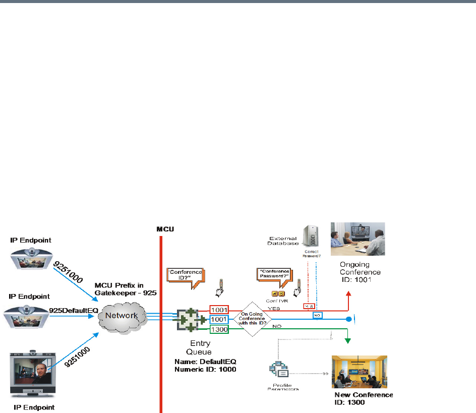
Appendix D - Ad Hoc Conferencing and External Database Authentication
Polycom®, Inc. 955
Conference access authentication can be performed as:
●Part of the Ad Hoc conferencing flow where the participants must be authorized before they can enter
the conference created in the Ad Hoc flow
●Independent of Ad Hoc conferencing where conference access is validated for all conferences
running on the MCU regardless of the method in which the conference was started.
Conference access authentication can be implemented for all participants joining the conference or for
chairpersons only.
Conference Access Validation - All Participants (Always)
Once the conference is created either via an Ad Hoc Entry Queue, or a standard ongoing conference, the
right to join the conference is authenticated with the external database application for all participants
connecting to the conference.
Conference Access - Conference Password validation with External Database Application
Joining the conference entails the following steps:
●When the conference is started (either in the Ad Hoc flow or in the standard method), all participants
connecting to the conference are moved to the Conference IVR queue where they are prompted for
the conference password.
●When the participant enters the conference password or his/her personal password, it is sent to the
external database application for validation.
●If there is a match, the participant is granted the right to join the conference. In addition, the external
database application sends to the MCU the following parameters:
Participant name (display name)
Whether or not the participant is the conference chairperson
Participant Information, such as the participant E-mail. These fields correspond to Info 1, 2, 3 and
4 fields in the Participant Properties - Information dialog box.
If there is no match (i.e. the conference or personal password are not defined in the database), the
request to access the conference is rejected and the participant is disconnected from the MCU.
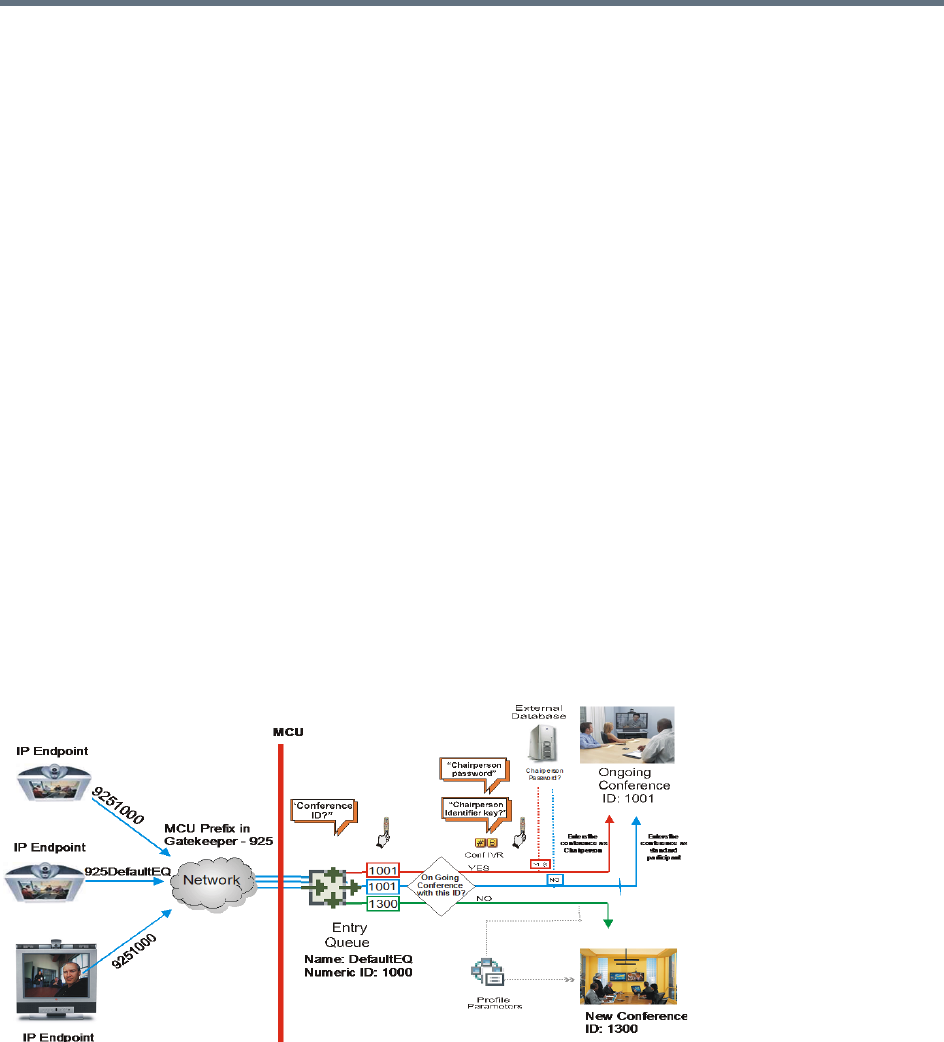
Appendix D - Ad Hoc Conferencing and External Database Authentication
Polycom®, Inc. 956
●If the Conference IVR Service is configured to prompt for the chairperson identifier and password,
the participant is requested to enter the chairperson identifier.
If no identifier is entered, the participant connects as a standard, undefined participant.
●If the chairperson identifier is entered, the participant is requested to enter the chairperson password.
In this flow, the chairperson password is not validated with the external database application, only
with the MCU.
If the correct chairperson password is entered, the participant is connected to the conference as
its chairperson.
If the wrong password is entered, he/she is disconnected from the conference.
To enable conference access validation for all participants the following conferencing components are
required:
●The external database must hold the conference password or the participant personal password/PIN
code or the participant’s Alias.
●The Conference IVR Service assigned to the conference (defined in the Profile) must be configured
to authenticate the participant’s right to access the conference with the external database application
for all requests. In addition it must be configured to prompt for the Conference Password.
Conference Access Validation - Chairperson Only (Upon Request)
An alternative validation method at the conference level is checking only the chairperson password with the
external database application. All other participants can be checked only with the MCU (if the Conference
IVR Service is configured to prompt for the conference password) or not checked at all (if the Conference
IVR Service is configured to prompt only for the chairperson password).
Conference Access - Chairperson Password validation with external database application
Joining the conference entails the following steps:
●When the conference is started (either in the Ad Hoc flow or in the standard method), all participants
connecting to the conference are moved to the conference IVR queue where they are prompted for
the conference password.

Appendix D - Ad Hoc Conferencing and External Database Authentication
Polycom®, Inc. 957
●If the Conference IVR Service is configured to prompt for the Conference password, the participant
is requested to enter the conference password. In this flow, the conference password is not validated
with the external database application, only with the MCU.
If the wrong password is entered, he/she is disconnected from the conference.
●If the correct conference password is entered, the participant is prompted to enter the chairperson
identifier key.
If no identifier is entered, the participant is connected to the conference as a standard participant.
●If the chairperson identifier is entered, the participant is prompted to enter the chairperson password.
●When the participant enters the chairperson password or his/her personal password, it is sent to the
external database application for validation.
If the password is incorrect the participant is disconnected from the MCU.
●If there is a match, the participant is granted the right to join the conference as chairperson. In
addition, the external database application sends to the MCU the following parameters:
Participant name (display name)
Participant Information, such as the participant E-mail. These fields correspond to Info 1, 2, 3 and
4 fields in the Participant Properties - Information dialog box.
To enable conference access validation for all participants, the following conferencing components are
required:
●The external database must hold the Chairperson Password or the participant’s Alias.
●The Conference IVR Service assigned to the conference (defined in the Profile) must be configured
to check the external database for the Chairperson password only when the participant enters the
chairperson identifier key (either pound or star). In addition, it must be configured to prompt for the
chairperson identifier key and password.
System Settings for Ad Hoc Conferencing and External
Database Authentication
Ad Hoc Settings
Before a participant can initiate an Ad Hoc conference (with or without authentication), the following
components must be defined:
●Profiles
Defines the conference parameters for the conferences that will be initiated from the Ad Hoc-enabled
Entry Queue. For more details, see Defining AVC-Based Conference Profiles and Defining SVC and
Mixed CP and SVC Conference Profiles.
●Entry Queue IVR Service with Conference ID Request Enabled
The Entry Queue Service is used to route participants to their destination conferences, or create a
new conference with this ID. For details, see IVR Services.
In Ad Hoc conferencing, the Conference ID is used to check whether the destination conference is
already running on the MCU and if not, to start a new conference using this ID.

Appendix D - Ad Hoc Conferencing and External Database Authentication
Polycom®, Inc. 958
●Ad Hoc - enabled Entry Queue
Ad Hoc conferencing must be enabled in the Entry Queue and a Profile must be assigned to the Entry
Queue. In addition, an Entry Queue IVR Service supporting conference ID request. For details, see
Entry Queues.
Authentication Settings
●MCU Configuration
Usage of an external database application for authentication (for starting new conferences or joining
ongoing conferences) is configured for the MCU in the System Configuration. For details, see System
Settings for Ad Hoc Conferencing and External Database Authentication.
●Entry Queue IVR Service with Conference Initiation Authentication Enabled
Set the Entry Queue IVR Service to send authentication requests to the external database application
to verify the participant’s right to start a new conference according to the Conference ID entered by
the participant. For details, see Enabling External Database Validation for Starting New Ongoing
Conferences.
●Conference IVR Service with Conference Access Authentication Enabled
Set the Conference IVR Service to send authentication requests to the external database application
to verify the participant’s right to connect to the conference as a standard participant or as a
chairperson. For details, see Enabling External Database Validation for Conferences Access.
●External Database Application Settings
The external database contains a list of participants (users), with their assigned parameters. These
parameters are:
Conference Name
Conference Billing code
Conference Password
Chairperson Password
Conference Information, such as the contact person name. These fields correspond to Info 1, 2
and 3 fields in the Conference Properties - Information dialog box.
Maximum number of participants allowed for the conference
Conference Owner
Participant name (display name)
Participant Information, such as the participant E-mail. These fields correspond to Info 1, 2, 3 and
4 fields in the Participant Properties - Information dialog box.
MCU Configuration to Communicate with an External Database Application
To enable the communication with the external database application, several flags must be set in the
System Configuration.
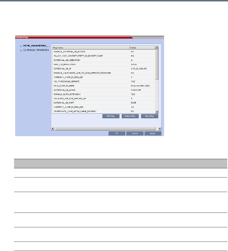
Appendix D - Ad Hoc Conferencing and External Database Authentication
Polycom®, Inc. 959
To set the System Configuration flags:
1On the Setup menu, click System Configuration.
The System Flags dialog box opens.
2Modify the values of the following flags:
3Click OK.
4Reset the MCU for flag changes to take effect.
Enabling External Database Validation for Starting New Ongoing Conferences
The validation of the participant’s right to start a new conference with an external database application is
configured in the Entry Queue IVR Service - Global dialog box.
Flag Values for Accessing External Database Application
Flag Description and Value
ENABLE_EXTERNAL_DB_ACCESS The flag that enables the use of the external database application.
EXTERNAL_DB_IP The IP address of the external database application server. default
IP: 0.0.0.0.
EXTERNAL_DB_PORT The port number used by the MCU to access the external
application server.
Default Port = 80.
EXTERNAL_DB_LOGIN The user name defined in the external database application for the
MCU.
EXTERNAL_DB_PASSWORD The password associated with the user name defined for the MCU in
the external database application.
EXTERNAL_DB_DIRECTORY The URL of the external database application.
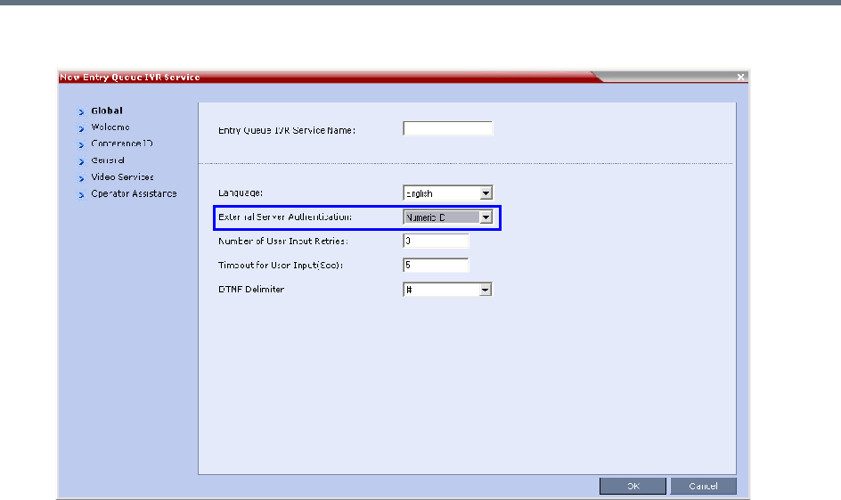
Appendix D - Ad Hoc Conferencing and External Database Authentication
Polycom®, Inc. 960
»Set the External Server Authentication field to Numeric ID.
Enabling External Database Validation for Conferences Access
The validation of the participant’s right to join an ongoing conference with an external database application
is configured in the Conference IVR Service - Global dialog box.
You can set the system to validate all the participants joining the conference or just the chairperson.
●Set the External Server Authentication field to:
Always - To validate the participant’s right to join an ongoing conference for all participants
Upon Request - To validate the participant’s right to join an ongoing conference as chairperson
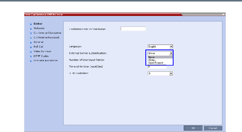
Appendix D - Ad Hoc Conferencing and External Database Authentication
Polycom®, Inc. 961

Polycom®, Inc. 962
Appendix E - Participant Properties
Advanced Channel Information
The following appendix details the properties connected with information about audio and video parameters,
as well as, problems with the network which can affect the audio and video quality.
Participant Properties - Channel Status Advanced Parameters
Field Description
Media Info
Algorithm Indicates the audio or video algorithm and protocol.
Frame per packet
(audio only)
The number of audio frames per packet that are transferred between the MCU
and the endpoint. If the actual Frame per Packets are higher than Frame per
Packets declared during the capabilities exchange, a Faulty flag is displayed.
Resolution
(video only)
Indicates the video resolution in use. If the actual resolution is higher than
resolution declared in the capabilities exchange, the Faulty flag is displayed.
For example, if the declared resolution is CIF and the actual resolution is 4CIF,
the Faulty flag is displayed.
Frame Rate
(video only)
The number of video frames per second that are transferred between the MCU
and the endpoint.
Annexes
(video only)
Indicates the H.263 annexes in use at the time of the last RTCP report. If the
actual annexes used are other than the declared annexes in the capabilities
exchange, the Faulty flag is displayed.
Channel Index For Polycom Internal use only.
RTP Statistics
Actual loss The number of missing packets counted by the IP card as reported in the last
RTP Statistics report. If a packet that was considered lost arrives later, it is
deducted from the packet loss count. Packet loss is displayed with the following
details:
• Accumulated N - number of lost packets accumulated since the channel opened.
• Accumulated % - percentage of lost packets out of the total number of packets
transmitted since the channel opened.
• Interval N - number of packets lost in the last RTP report interval (default interval is
5 minutes).
• Interval % - percentage of lost packets out of the total number of packets transmitted
in the last RTP report interval (default interval is 5 minutes).
• Peak - the highest number of lost packets in a report interval from the beginning of
the channel's life span.

Appendix E - Participant Properties Advanced Channel Information
Polycom®, Inc. 963
Out of Order The number of packets arriving out of order. The
following details are displayed:
• Accumulated N - total number of packets that arrived out of order since the channel
opened.
• Accumulated % - percentage of packets that arrived out of order out of the total
number of packets transmitted since the channel opened.
• Interval N - number of packets that arrived out of order in the last RTP report interval
(default interval is 5 minutes).
• Interval % - percentage of packets that arrived out of order out of the total number
of packets transmitted in the last RTP report interval (default interval is 5 minutes).
• Peak - the highest number of packets that arrived out of order in a report interval from
the beginning of the channel's life span.
Fragmented Indicates the number of packets that arrived to the IP card fragmented (i.e., a
single packet broken by the network into multiple packets). This value can
indicate the delay and reordering of fragmented packets that require additional
processing, but is not considered a fault.
The Fragmented information is displayed with the following details:
• Accumulated N - total number of packets that were fragmented since the channel
opened.
• Accumulated % - percentage of fragmented packets out of the total number of
packets transmitted since the channel opened.
• Interval N - number of fragmented packets received in the last RTP report interval
(default interval is 5 minutes).
• Interval % - percentage of fragmented packets out of the total number of packets
transmitted in the last RTP report interval (default interval is 5 minutes).
• Peak - the highest number of fragmented packets in a report interval from the
beginning of the channel's life span.
Participant Properties - Channel Status Advanced Parameters
Field Description

Polycom®, Inc. 964
Appendix F- Secure Communication
Mode
The RealPresence Collaboration Server can be configured to work in Secure Mode or Ultra Secure Mode.
For more information see Ultra Secure Mode and Flags Specific to Maximum Security Environments - Ultra
Secure Mode.
In Secured mode the Collaboration Server and the Collaboration Server Web Client are configured to work
with SSL/TLS.
In this mode, a SSL/TLS Certificate is installed on the MCU, setting the MCU Listening Port to secured port
443.
TLS is a cryptographic protocol used to ensure secure communications on public networks. TLS uses a
Certificate purchased from a trusted third party Certificate Authority to authenticate public keys that are used
in conjunction with private keys to ensure secure communications across the network.
The Collaboration Server supports:
●TLS 1.0
●SSL 3.0 (Secure Socket Layer)
SSL 3.0 utilizes 1024-bit RSA public key encryption.
TLS certificates can be generated using the following methods: CSR, PFX and PEM; each giving different
options for Encryption Key length. The table below lists the SIP TLS Encryption Key length support for the
various system components.
Certificate Configuration and Management
All Polycom devices used in a Maximum Security Environment require security certificates.
For more details see the Ultra Secure Mode chapter, Certificate Management.
Certificate Template Requirements
The specific security certificate requirements for Collaboration Servers used in Maximum Security
Environments are:
●Support of 2048-bit encryption keys.
SIP TLS - Encryption Key Support by System Component
System Component Key Generation Method Key Length (bits) Key generated by
SIP Signaling CSR 2048 Collaboration
Server
PFX / PEM 1024 or 2048 User
Management
CSR 2048 Collaboration
Server
LDAP

Appendix F- Secure Communication Mode
Polycom®, Inc. 965
●Support of Extended Key Usage (EKU) for both:
Client Authentication
Server Authentication
The certificate template used by your CA server may need modification to meet the Collaboration Server
requirements.
Certificate Requirements
Secure Mode
In Secure Mode, the certificate requirements depend on the Skip certificate validation for user logging
session field.
Ultra Secure Mode
In Ultra Secure Mode, each Polycom device must have security certificates for the entire Chain Of Trust.
The Collaboration Server must have:
●The public certificate of each server in the CA Chain or hierarchy that issued its certificate.
For example: RootCA > IntermediateCA > SubCA
●The public certificates of the chain that issued the administrator’s identity certificate.
For example: UserRootCA > UserIntermediateCA > UserSubCA
For more information see Ultra Secure Mode chapter, Certificate Validation and Certificate Revocation.
Configure Certificate Management
Within a PKI environment, certificate revocation policies are used to ensure that certificates are valid.
Certificates can expire or be revoked for various reasons (RFC 5280).
The Collaboration Server enforces these certificate revocation policies through Certificate Revocation Lists
(CRLs). CRLs are required for each CA Chain in use by the Collaboration Server. These CRL files must be
kept current. For more information see the Ultra Secure Mode chapter, Certificate Configuration and
Management and (PKI) Public Key Infrastructure.
Switching to Secure Mode
The following operations are required to switch the Collaboration Server to Secure Mode:
●Purchase and Install the SSL/TLS certificate
●Modify the Management Network settings
●Create/Modify the relevant System Flags
Purchasing and Installing a Certificate
Once a certificate is purchased and received it is stored in the Collaboration Server and used for all
subsequent secured connections. For more information see the Ultra Secure Mode chapter, Adding
Certificates to the Certificate Repository.
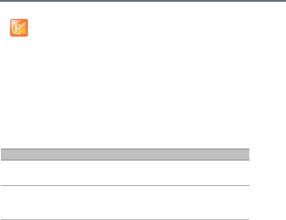
Appendix F- Secure Communication Mode
Polycom®, Inc. 966
Creating/Modifying System Flags
The following System Flags in system.cfg control secure communications.
●RMX_MANAGEMENT_SECURITY_PROTOCOL
●EXTERNAL_DB_PORT
The table below lists both flags and their settings.
If the System Flag, RMX_MANAGEMENT_SECURITY_PROTOCOL does not exist in the system, it must
be created by using the Setup menu.
For more information see Modifying System Flags.
The Collaboration Server must be restarted for modified flag settings to take effect.
Enabling Secure Communication Mode
After the SSL/TLS Certificate is installed, secure communications are enabled by modifying the properties
of the Management Network in the Management Network properties dialog box.
When Secure Communications Mode is enabled:
●Only https:// commands from the browser to the Control Unit IP Address of the Collaboration
Server are accepted.
●The Collaboration Server listens only on secured port 443.
●All connection attempts on port 80 are rejected.
●A secure communication indicator is displayed in the browser’s status bar.
To enable secure communications mode:
1In the Collaboration Server Management pane, click IP Network Services.
2In the IP Network Services list pane, double-click the Management Network entry.
Certificates are deleted when an administrator performs a Restore Factory Defaults with the
Comprehensive Restore option selected.
System Flags
Flag Description
RMX_MANAGEMENT_S
ECURITY_PROTOCOL
Enter the protocol to be used for secure communications.
Default: TLSV1_SSLV3 (both).
Default for U.S. Federal licenses: TLSV1.
EXTERNAL_DB_PORT The external database server port used by the Collaboration Server to
send and receive XML requests/responses.
For secure communications set the value to 443.
Default: 5005.
Appendix F- Secure Communication Mode
Polycom®, Inc. 967
3Click the Security tab.
The Management Security Properties dialog box is displayed.
4Select the Secured Communication check box.
5Select the Certificate Validation mode by checking or clearing the Skip certificate validation for
user logging session field as set out in the following table:
6Click OK.
Management Network Properties - Certificate Validation Mode
Field: Skip certificate validation for user logging session
Status RMX and Client Certificate Requirements
Un-checked
(Restricted Mode)
•The RMX must install a personal certificate issued by a CA.
•The Client must install a personal certificate issued by a CA.
•The public key of the CA must be installed in the RMX.
Note: When the RMX Manager is the Client, all Personal Certificates
in the workstation's Certification Repository are sent to the RMX.
When using the RMX Web Client, Internet Explorer gives the user the
option to select the Personal Certificate to be used from the
workstation's Certification Repository.
Checked
(Un-restricted Mode)
•The RMX must install a personal certificate issued by a CA.
•No additional configuration is required for the Client.

Appendix F- Secure Communication Mode
Polycom®, Inc. 968
Alternate Management Network
The Alternate Management Network enables direct access to the Collaboration Server for support
purposes. Access to the Alternate Management Network is via a cable connected to a workstation. The
Alternate Management Network is accessible only via the dedicated LAN 3 port.
For more information see:
●Appendix G - Configuring Direct Connections to the Collaboration Server
●Connect to the Alternate Management Network (1500/2000/4000)
Restoring Defaults
For details see Appendix J - Restore Defaults.
Connection to the Alternate Management Network bypasses LAN and Firewall security. Strict control
of access to LAN 3 port is recommended.

Polycom®, Inc. 969
Appendix G - Configuring Direct
Connections to the Collaboration Server
Direct connection to the Collaboration Server is necessary if you want to:
●Modify the Collaboration Server’s Factory Default Management Network settings without using the
USB memory stick.
●Connect to the Collaboration Server’s Alternate Management Network for support purposes.
●Connect to the Collaboration Server via a modem.
Management Network (Primary)
If you do not want to use the USB memory stick method of modifying the Collaboration Server’s
Management Network parameters, it is necessary to establish a direct connection between a workstation
and the Collaboration Server.
Alternate Management Network (1500/2000/4000)
The Alternate Management Network enables direct access to the Collaboration Server (RMX) 1500/
2000/4000) for support purposes.
While being separate from all other networks, it has identical functionality to the Management Network.
Support personnel can log in and use it to manage the Collaboration Server if a connection to the
Management Network cannot be made or if internet access to the host network is blocked by LAN security
or a firewall.
The Alternate Management Network cannot be configured and operates according to factory defaults.
The administrator’s Login name, Password, viewing and system permissions on the Alternate Management
Network are the same as those on the Management Network.
Once logged in, the RP Collaboration Server Web Client behaves as if the administrator had logged in on
the Management Network.
Configure the Workstation
The following procedures show how to modify the workstation’s networking parameters using the Windows
New Connection Wizard.
Note: Ultra Secure Mode
Direct connections to the Collaboration Server are not supported when the Collaboration Server is in
Ultra Secure Mode. For more information see Ultra Secure Mode.
Note: Security
•Connection to the Alternate Management Network bypasses LAN and Firewall security. Strict
control of access to LAN 3 port is recommended.
•The Alternate Management Network is only available if Network Separation has not been
performed. For more information, see Multiple Network Services.
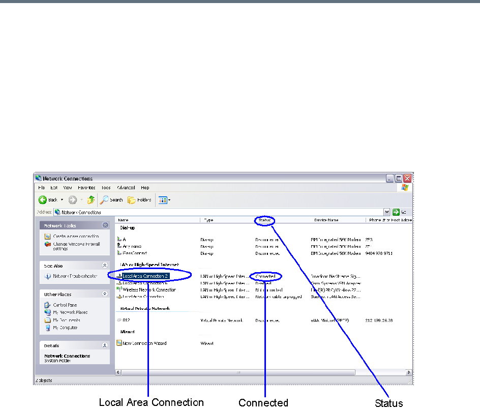
Appendix G - Configuring Direct Connections to the Collaboration Server
Polycom®, Inc. 970
For non-Windows operating systems an equivalent procedure must be performed by the system
administrator.
Before connecting directly, you must modify the IP Address, Subnet Mask and Default Gateway settings of
the workstation to be compatible with either the Collaboration Server’s Default Management Network or
Alternate Management Network.
To modify the workstation’s IP addresses:
1On the Windows Start menu, select Settings > Network Connections.
2In the Network Connections window, double-click the Local Area Connection that has Connected
status.
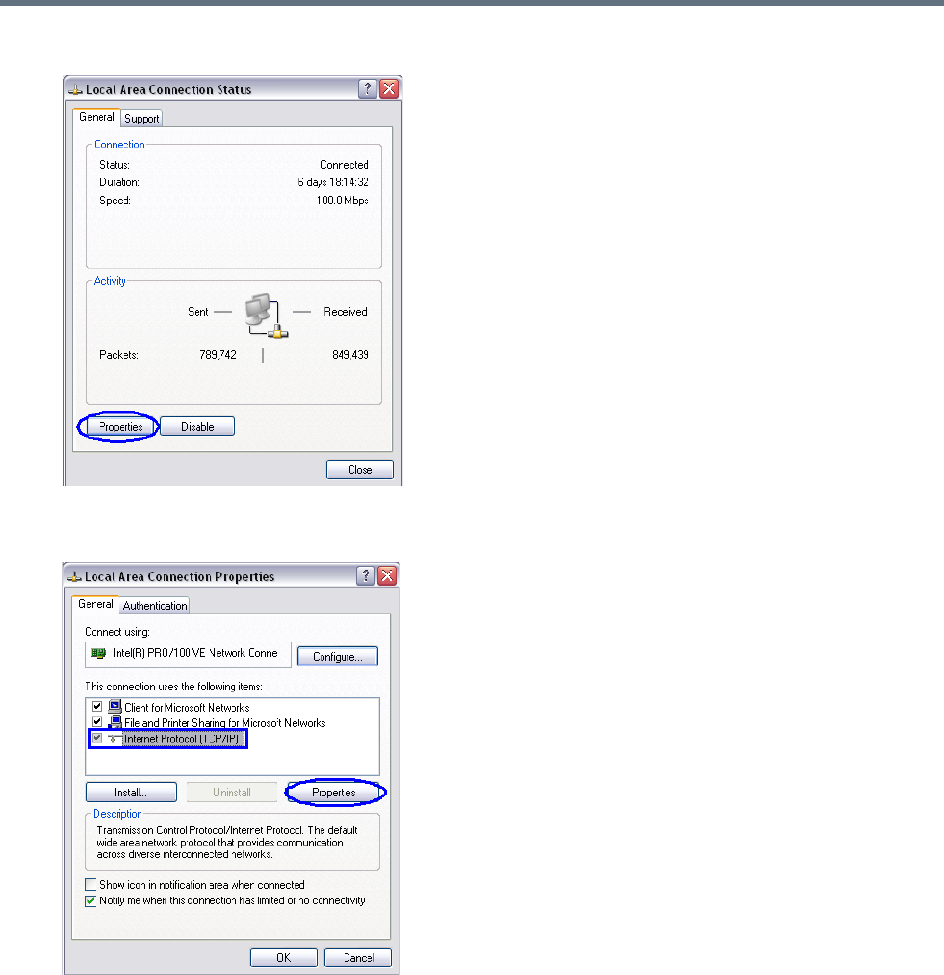
Appendix G - Configuring Direct Connections to the Collaboration Server
Polycom®, Inc. 971
3In the Local Area Connection Status dialog box, click Properties.
4In the Local Area Connection Properties dialog box, select Internet Protocol [TCP/IP] >
Properties.
5In the Internet Protocol (TCP/IP) Properties dialog box, select Use the following IP address.
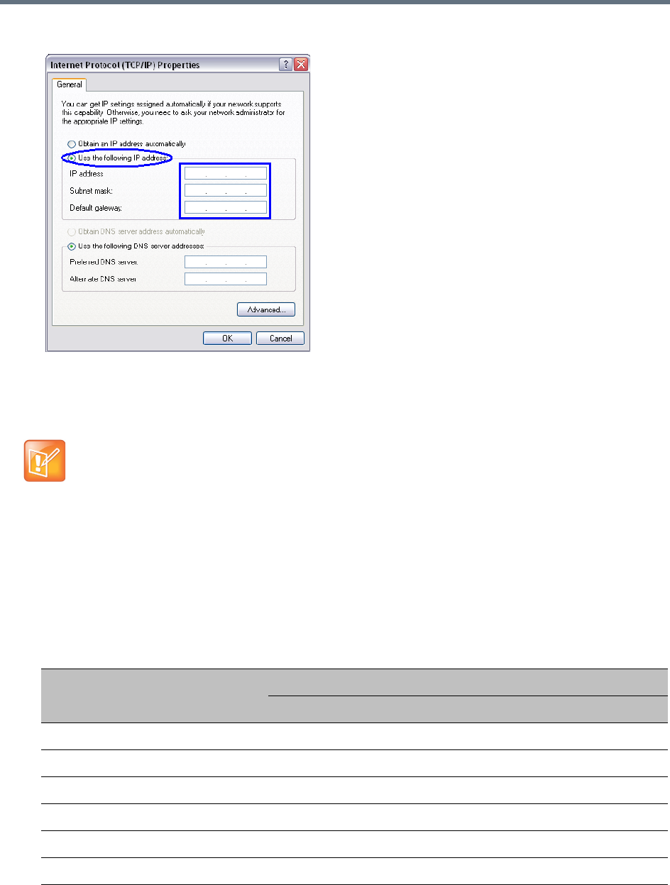
Appendix G - Configuring Direct Connections to the Collaboration Server
Polycom®, Inc. 972
6Enter the IP address, Subnet mask and Default gateway for the workstation.
The workstation’s IP address should be in the same network neighborhood as the Collaboration
Server’s Control Unit IP address.
Example: IP address – in the network neighborhood of 192.168.1.nn
The Subnet mask and Default gateway addresses should be the same as those for the Collaboration
Server’s Management Network.
The addresses needed for connection to either the Collaboration Server’s Default Management
Network or Alternate Management Network are listed in the table below.
For more information about connecting to the Alternate Management Network, see Appendix G -
Configuring Direct Connections to the Collaboration Server.
Note: Reserved IP Addresses
None of the reserved IP addresses listed in Reserved IP Addresses list below should be used for the
IP Address.
Reserved IP Addresses
Network Entity
IP Address
Management Network (Factory Default) Alternate Network
Control Unit IP Address 192.168.1.254 169.254.192.10
Control Unit Subnet Mask 255.255.255.0 255.255.240.0
Default Router IP Address 192.168.1.1 169.254.192.1
Shelf Management IP Address 192.168.1.252 169.254.192.16
Shelf Management Subnet Mask 255.255.255.0 255.255.240.0
Shelf Management Default Gateway 192.168.1.1 169.254.192.1
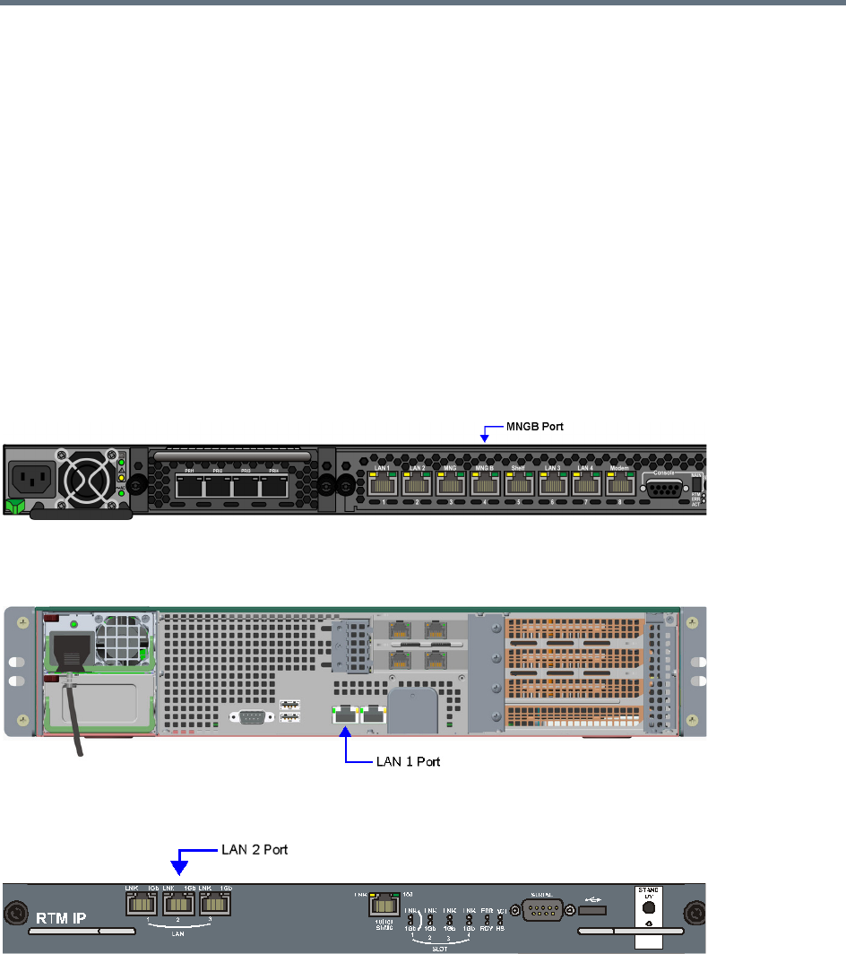
Appendix G - Configuring Direct Connections to the Collaboration Server
Polycom®, Inc. 973
7Click the OK button.
Connect to the Management Network
Connection to the Management Network is done using the following procedure.
To connect directly to the Collaboration Server:
1Using a LAN cable, connect the workstation:
To the MNGB Port on the Collaboration Server (RMX) 1500 back panel.
To the LAN 1 Port on the Collaboration Server (RMX) 1800 back panel.
To the LAN 2 Port on the Collaboration Server (RMX) 2000/4000 back panel.
Collaboration Server (RMX) 1500
Collaboration Server (RMX) 1800
Collaboration Server (RMX) 2000
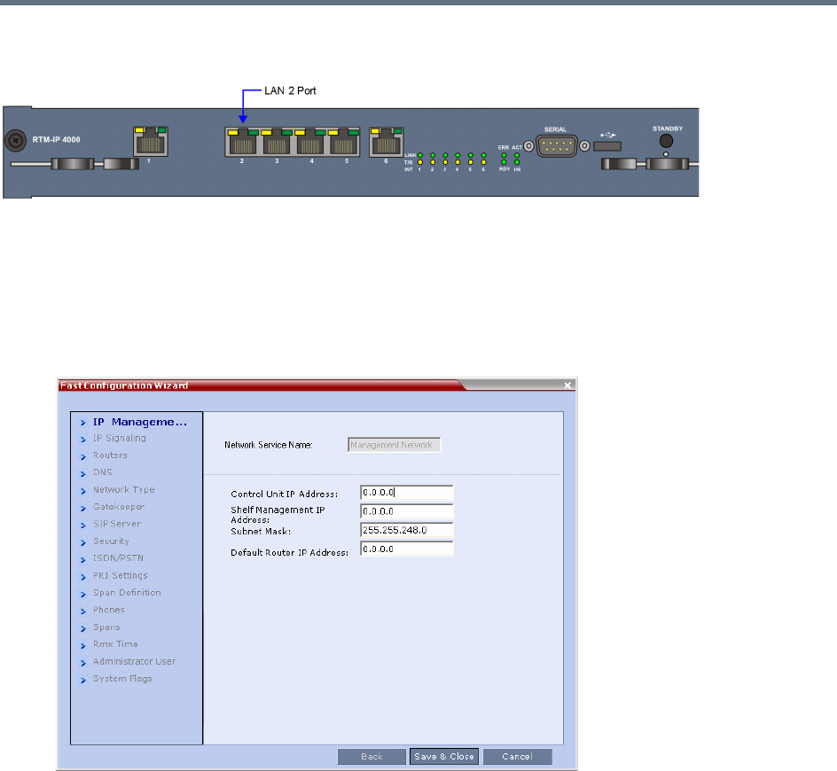
Appendix G - Configuring Direct Connections to the Collaboration Server
Polycom®, Inc. 974
Collaboration Server (RMX) 4000
2Connect the power cable and power the Collaboration Server On.
3Start the Collaboration Server Web Client application on the workstation, by entering the factory
setting Management IP address in the browser’s address line and pressing Enter.
4In the Collaboration Server Web Client Login screen, enter the default Username (POLYCOM) and
Password (POLYCOM) and click the Login button.
The Fast Configuration Wizard starts.
For more information about First-time Power-up and the Fast Configuration Wizard see Procedure 1:
First-time Power-up in the Polycom RealPresence Collaboration Server (RMX)
1500/1800/2000/4000 Getting Started Guide.
5Enter the following parameters using the information supplied by your network administrator:
Control Unit IP Address
Shelf Management IP Address
Control Unit Subnet Mask
Default Router IP Address
6Click the Save & Close button.
The system prompts you to sign in with the new Control Unit IP Address.
7Disconnect the LAN cable between the workstation and the LAN 2 Port on the Collaboration
Server’s back panel.
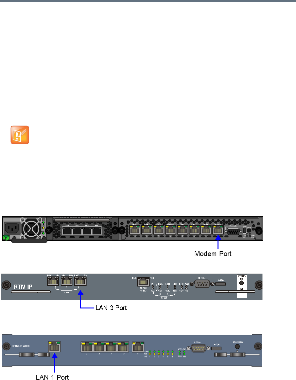
Appendix G - Configuring Direct Connections to the Collaboration Server
Polycom®, Inc. 975
8Connect LAN 2 Port on the Collaboration Server’s back panel to the local network using a LAN
cable.
9Enter the new Control Unit IP Address in the browser’s address line, using a workstation on the
local network, and press Enter to start the Collaboration Server Web Client application.
10 In the Collaboration Server Web Client Login screen, enter the default Username (POLYCOM) and
Password (POLYCOM) and click the Login button.
Connect to the Alternate Management Network
(1500/2000/4000)
The Alternate Management Network enables direct access to the Collaboration Server for support
purposes.
The Alternate Management Network is only accessible using a LAN cable, connecting the pre-configured
workstation to the appropriate port on the Collaboration Server:
●Collaboration Server (RMX) 1500 — Modem port
●Collaboration Server (RMX) 2000 — LAN 3 port
●Collaboration Server (RMX) 4000 — LAN 1 port
Collaboration Server (RMX) 1500
Collaboration Server (RMX) 2000
Collaboration Server (RMX) 4000
Note: Alternate Management Network
The Alternate Management Network cannot be configured and operates on factory defaults.
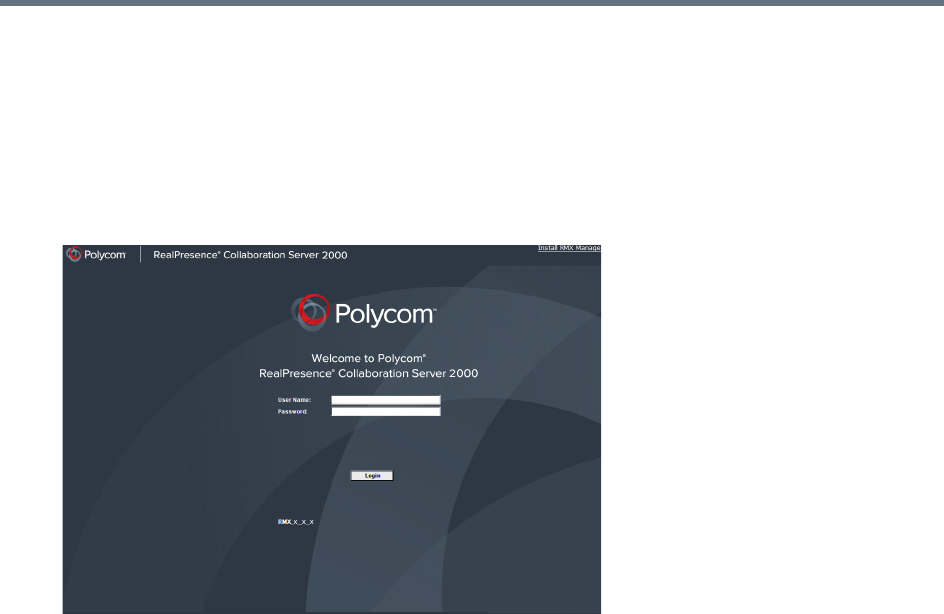
Appendix G - Configuring Direct Connections to the Collaboration Server
Polycom®, Inc. 976
To connect to the Alternate Management Network:
1Connect the cable between the relevant Collaboration Server port and the LAN port configured on
the workstation.
2Start the Collaboration Server Web Client application on the workstation, by entering
http://169.254.192.10 (the Control Unit IP Address) in the browser’s address line and press
Enter.
The Login dialog box is displayed.
3In the RealPresence Collaboration Server Welcome Screen, enter the administrator’s Username
and Password and click the Login button.
The RealPresence Collaboration Server Web Client starts and the Collaboration Server can be
managed in the same manner as if you had logged on to the Management Network.

Appendix G - Configuring Direct Connections to the Collaboration Server
Polycom®, Inc. 977
Connect to the Collaboration Server using a Modem
(1500/2000/4000)
Remote access to the Collaboration Server’s Alternate Management Network is supported via an external
PSTN <=> IP modem.
To connect via modem to the Alternate Management Network perform the following procedures:
1 Procedure 1: Install the RMX Manager – The web client enables direct access to the Collaboration
Server for support purposes.
2 Procedure 2: Configure the modem – By assigning it an IP address on a specific subnet in the
Alternate Management Network.
3 Procedure 3: Create a dial-up connection – Using Windows New Connection Wizard.
4 Procedure 4: Connect to the Collaboration Server – Via the RMX Manager.
Procedure 1: Install the RMX Manager
Before installing the RMX Manager, verify that you have at least 150Mb of free space on your workstation.
For more information see Installing the RMX Manager Application.
Procedure 2: Configure the Modem
Configure the modem with the following settings.
●IP address – near 169.254.192.nn
●Subnet Mask – 255.255.240.0
Procedure 3: Create a Dial-up Connection
This procedure is performed once. Only the Dial field in the Connect applet (see step 10 on Click the Dial
button to establish a connection to LAN 3 Port via the modem.) is modified for connection to different
modems.
To create a dial-up connection:
1In Windows, navigate via the Control Panel to the Network Connections applet and select Create
a new connection.
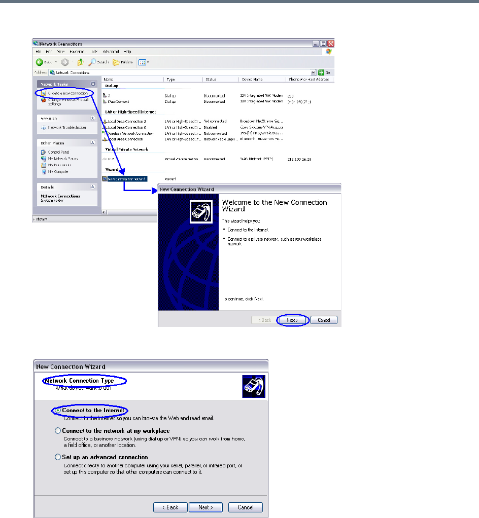
Appendix G - Configuring Direct Connections to the Collaboration Server
Polycom®, Inc. 978
2When the New Connection Wizard is displayed, click Next.
3In the Network Connection Type box, select Connect to the Internet and click Next.
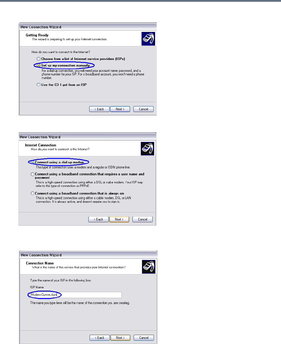
Appendix G - Configuring Direct Connections to the Collaboration Server
Polycom®, Inc. 979
4In the Getting Ready box, select Set up my connection manually and click the Next button.
5In the Internet Connection box, select Connect using dial-up modem and click the Next button.
6In the Connection Name box, enter a Name for the modem connection (e.g. Modem Connection)
and click the Next button.
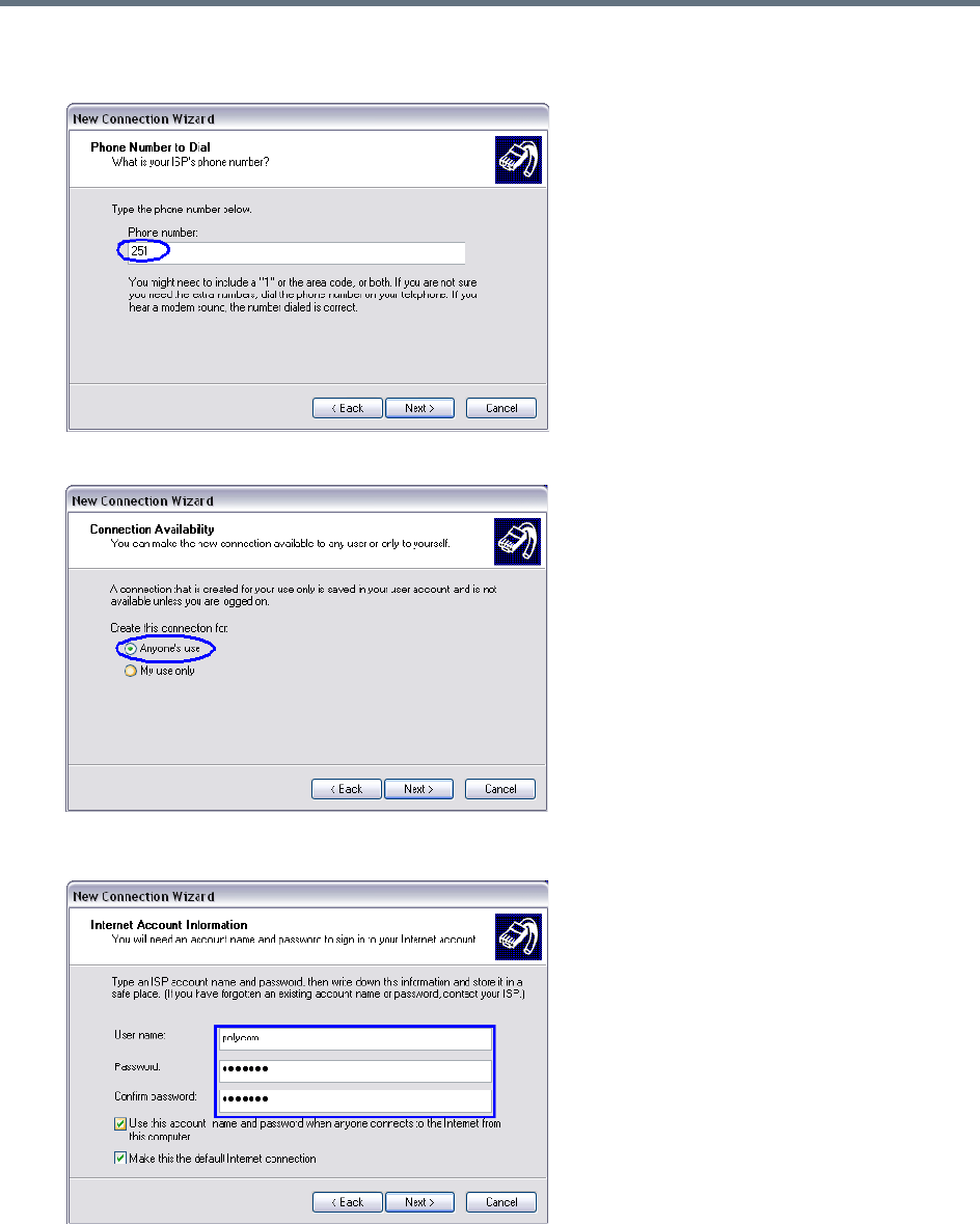
Appendix G - Configuring Direct Connections to the Collaboration Server
Polycom®, Inc. 980
7In the Phone Number to Dial box, enter the Phone Number for the modem and click the Next
button.
8In the Connection Availability box, select Anyone’s use and click the Next button.
9In the Internet Account Information box, complete the Username, Password and Confirm
Password fields and click the Next button.
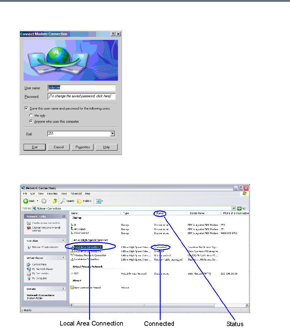
Appendix G - Configuring Direct Connections to the Collaboration Server
Polycom®, Inc. 981
10 The Connection applet is displayed with the field values filled in as specified by the New
Connection Wizard.
11 Click the Dial button to establish a connection to LAN 3 Port via the modem.
The Windows – Network Connections applet displays Connected status for the new connection.

Appendix G - Configuring Direct Connections to the Collaboration Server
Polycom®, Inc. 982
Procedure 4: Connect to the Collaboration Server
To Connect using the RMX Manager:
To use the browser:
»In the browser’s command line, enter http://<MCU Control Unit IP Address>/RmxManager.html
and press Enter.
To use the Windows Start menu:
1Click Start.
aIf the RMX Manager is displayed in the Recently used programs list, click RMX Manager in the
list to start the application.
or
bClick All Programs.
The All Programs list is displayed.
2Select Polycom and then select RMX Manager.
The RMX Manager – Welcome screen is displayed.

Polycom®, Inc. 983
Appendix H - Deployment Into Microsoft
Environments
Overview
Polycom® RealPresence Collaboration Server platforms and Polycom Unified Communications (UC)
software and products can be deployed in Microsoft® Lync™ 2010 and 2013 environments.
This chapter describes solution architecture options, and conferencing features supported in the
deployment of Polycom’s RealPresence Collaboration Server platforms into Microsoft® Lync™ 2010 and
2013 environments.
The following topics are covered in this chapter:
●Lync 2013 SVC Connectivity to RealPresence Collaboration Servers
●Connecting a Collaboration Server Meeting Room to a Microsoft AV-MCU Conference
●Call Admission Control
●Active Alarms and Troubleshooting
A description of the full Polycom UC solution for Microsoft environments can be found in the Polycom®
Unified Communications in a Microsoft® Environment Solution Deployment Guide, which includes the
following topics:
●Polycom Products Tested for use with this Solution
●Deploy Polycom® RealPresence Group Series® Systems
●Deploy Polycom® HDX® Systems
●Deploy Polycom® Immersive Telepresence (ITP) Systems
●Deploy Polycom® RealPresence Collaboration Server (RMX) Systems
●Deploy Polycom® RealPresence DMA® Systems
●Deploy Polycom® Conferencing for Microsoft® Outlook
This Solution Deployment Guide and additional reference material on Polycom solutions with Microsoft can
be found at: http://support.polycom.com/microsoft

Appendix H - Deployment Into Microsoft Environments
Polycom®, Inc. 984
Lync 2013 SVC Connectivity to RealPresence
Collaboration Servers
Microsoft’s H.264 SVC codec has replaced RTV as the preferred codec for enabling video calls between
Lync 2013 clients (endpoints) and Polycom endpoints, in the same as manner as RTV replaced H.263 as
the preferred codec in previous versions. For backward compatibility, RTV is still supported for both Lync
2010 and 2013.
Although similar, the Microsoft H.264 SVC codec is not compatible with, and should not be confused with
Polycom’s standards-based H.264 and SVC implementation.
The Collaboration Server considers Lync 2010 and H.264 SVC Lync 2013 clients to be AVC endpoints. The
administrator must set the Conferencing Mode in the Conference Profile to CP (Continuous Presence) to
enable H.264 SVC Lync clients to connect to the conference.
Deployment Architectures
Two Deployment Architectures are presented as examples. Both require that a Polycom RealPresence
Distributed Media Application (DMA) System 7000 be configured as part of the solution.
Although Cisco legacy endpoints are inter-operable with Collaboration Server (RMX) 1800-0, the MCU is
not supported for integration into third-party and partner environments.
●Deployment Architecture 1 - RealPresence Hosted Conferences (Direct)
Both Lync clients and Standards-based video endpoints connect directly to the same conference
hosted only on the Polycom RealPresence Collaboration Server.
●Deployment Architecture 2 - RealConnect Cascaded Conferences
Lync clients connect to a conference on the Lync 2013 AVMCU while Standards-based video
endpoints content to a separate conference on the Polycom RealPresence Collaboration Server. The
two MCUs are cascaded together to form a single conference including all participants.
Note: Collaboration Server (RMX) 1800-0
Collaboration Server (RMX) 1800-0, is not supported for integration into third-party and partner
environments.
Appendix H - Deployment Into Microsoft Environments
Polycom®, Inc. 985
The following table summarizes current and legacy (non DMA) conferencing modes within the deployment
architectures:
Backward Compatibility to Lync 2010
All Lync 2013 functionality can be disabled by adding the BLOCK_NEW_LYNC2013_FUNCTIONALITY
System Flag and setting its value to YES.
The flag’s default value is NO. When the flag is set to YES, all Lync 2013’s new functionality is disabled. All
Lync 2013 clients, whether connected directly or via cascading, will connect using the RTV codec, and not
the Microsoft H.264/SVC codec.
Conference Modes by Deployment Architecture
Conference
Mode
Deployment Architecture 1
RealPresence Hosted
Conferences
(Direct Dial In/Out)
With or without DMA
Deployment Architecture 2
Lync 2013 AVMCU Cascaded Conferences
(Indirect Dial In)
With DMA
(RealConnect)
Non DMA
(Backward Compatibility)
AVC Only Supported.
Dial Out from DMA is not
supported.
For backward compatibility,
Dial out from the RMX Web
Client or RMX Manager can
be used.
When using backward
compatibility mode for Dial
Out, the default video
protocol of H.264/SVC in
Lync 2013 clients is not
supported. Instead RTV will
be utilized, as long as that
codec has not been manually
disabled on the Collaboration
Server configuration using
any related system flag
setting which are covered
later in this section.
Supported.
Simulcast transmitted.
Multiple participants received.
Supported.
One transmitted RTV stream.
One received RTV stream.
Mixed Mode Supported Not Supported
SVC Only Not Supported
Appendix H - Deployment Into Microsoft Environments
Polycom®, Inc. 986
Video Resource Requirements and Implications
Lync 2013 SVC clients may not all connect to a VMR with the same stream layout. They are therefore
considered H.264 AVC participants and transcoding resources are allocated to them as summarized in the
following table.
Support for HD1080p Resolution
The Collaboration Server Hosted deployment supports HD1080p30 video resolution symmetrically for direct
calls.
The MS AV MCU Cascade deployment supports HD1080p30 video resolution only if
Video Optimized
mode
is selected and according to the settings of the LYNC_AVMCU_1080p30_ENCODE _RESOLUTION
System Flag:
NO (Default) Video streams sent to and received from the MS AV MCU are HD720p30, SD, and CIF.
YES Video streams sent to the MS AV MCU are HD1080p30, SD, CIF. Video streams received from
the MS AV MCU are 720p30,SD, and CIF.
Bandwidth and Resource Consumption by Video Codec
Video Codec Resolution and Aspect
Ratio
Maximum Video
Payload Bit rate
(Kbps)
Minimum Video
Payload Bit rate
(Kbps)
Resources
H.264 320x180 (16:9)
Coded as 320x192
212x160 (4:3)
250 15 CIF
H.264/RTVideo 424x240 (16:9)
Coded as 432x240
320x240 (4:3)
350 100 CIF
H.264 480x270 (16:9)
Coded as 480x272
424x320 (4:3)
Coded as 432x320
450 200 SD
H.264/RTVideo 640x360 (16:9)
Coded as 640:368
640x480 (4:3)
800 300 SD
H.264 848x480 (16:9) 1500 400 SD
H.264 960x540 (16:9)
Coded as 960:544
2000 500 SD
H.264/RTV 1280x720 (16:9) 2500 700 HD720p30
H.264 1920x1080 (16:9) 4000 1500 HD1080p30

Appendix H - Deployment Into Microsoft Environments
Polycom®, Inc. 987
Limit Maximum Resolution for MS SVC Using a System flag
The MAX_MS_SVC_RESOLUTION System Flag can be used to minimizing the resource usage by
overriding the default resolution selection and limiting it to a lower resolution.
Range: AUTO, CIF, VGA, HD720, HD1080
Default: AUTO
The MAX_MS_SVC_RESOLUTION System Flag operates independently from the
MAX_RTV_RESOLUTION System Flag allowing differing maximum resolutions to be selected for the MS
SVC and RTV protocols.
If you want to modify System Flag values, the flags must be added to the System Configuration file. For
more information see:
Modifying System Flags
and Controlling Resource Allocations for Lync Clients Using
RTV Video Protocol.
FEC (Forward Error Correction)
FEC is supported for RTV and MS SVC video protocols.
●FEC will be automatically turned on by the VSR (Video Source Request) message.
Redundant Audio Data (RED) is supported for the following Audio CODECS:
●G.722
●G.711A
●G.711U
The Collaboration Server transmits RED when packet loss is reported and stops sending RAD when packet
loss is stopped.
For more information see Lost Packet Recovery.
IPv6 Support
In addition to IPv4, IPv6 is supported in Lync 2013 environments.
Following IP modes are supported for all network connections—ICE, Media, Management, Signaling, etc.:
●IPv4 only
●IPv6 only
●IPv4 & IPv6
As in previous versions, IPv4 Candidates are advertised first in the SDP.
IPv6 is not supported by Lync 2010. All dial out calls from the Collaboration Server are considered Lync
2010 calls and utilize IPv4.
Dial out calls from DMA to Lync environments are considered to be dial in calls from the Collaboration
Server perspective.
The ANAT (Alternative Network Address Types) option is not applicable in Lync environments.
For more information see IPv6 Addressing Guidelines.
DHCPv6 Support for Auto IPv6 Address Assignment
DHCPv6 Auto IPv6 Addresses Assignment, as required by Lync 2013 environments is supported.

Appendix H - Deployment Into Microsoft Environments
Polycom®, Inc. 988
As in previous versions, SLAAC (Stateless Address Auto Configuration) continues to be supported.
System behavior can be controlled by adding the IPV6_AUTO_ADDRESS_CONFIGURATION_METHOD
System Flag and setting its value as required.
AUTO—(default) Use DHCPv6 first in case of failure use SLAAC.
SLAAC—Use SLAAC only.
For more information see,
Modifying System Flags
.
System Flags for Cropping Control
Cropping occurs when the video source (endpoint) aspect ratio is different from the video cell aspect ratio
in the Polycom Video Layout.
For all endpoints other than ITP endpoints and panoramic cells the Collaboration Server calculates the
mismatch percentage between the source video aspect ratio and Polycom video layout cell aspect ratio. The
mismatch percentage is used to determine whether cropping or striping will be applied to the video cell in
the Polycom video layout.
For non-panoramic layouts, cropping and striping can be controlled by adding the
CROPPING_PERCENTAGE_THRESHOLD_GENERAL System Flag and setting its value accordingly.
For panoramic layouts, cropping and striping can be controlled by adding the
CROPPING_PERCENTAGE_THRESHOLD_PANORAMIC System Flag and setting its value accordingly.
For both System Flags:
Range: -1-100.
Default: -1
If the calculation result is less than or equal to the value of the
CROPPING_PERCENTAGE_THRESHOLD_GENERAL System Flag, cropping will be applied.
If the calculation result is greater than the value of the
CROPPING_PERCENTAGE_THRESHOLD_GENERAL System Flag, striping will be applied.
If the CROPPING_PERCENTAGE_THRESHOLD_GENERAL System Flag value is set to 0, cropping will
not be applied.
If the CROPPING_PERCENTAGE_THRESHOLD_GENERAL System Flag value is set to -1 cropping will
always be applied.
If the CROPPING_PERCENTAGE_THRESHOLD_GENERAL System Flag value is set to 100, always
apply cropping with the exception of mobile aspect ratios. Mobile aspect ratios are those with a larger
vertical aspect than horizontal for example 3:4.
Example: A mobile Lync client sends 288x352 (3:4) aspect ratio. Cropping this resolution to 16:9 would
require the cropping of 190 pixels on the vertical aspect. The mismatch calculation would yield 190/352 ~54.
If the applicable System Flag's value is set to >= 54, striping, rather than cropping, is applied.
For more information see,
Modifying System Flags
.

Appendix H - Deployment Into Microsoft Environments
Polycom®, Inc. 989
Sharing Content During a Conference
Two implementations of the Content Sharing Suite (CSS) are available in Lync 2010 and Lync 2013
environments:
●RealPresence CSS Gateway
●RealPresence CSS Plug in
RealPresence CSS Gateway
The CSS Gateway provides Content interoperability between Lync clients and non Lync clients in a
conference. Lync clients connected to a Lync AV MCU use their native Content protocol, RDP (Remote
Desktop Protocol) and Polycom endpoints, use their native SIP BFCP Content protocol, to send or receive
Content, to or from the CSS Gateway, which renders a RDP SIP BFCP Content stream.
The Gateway functionality was previously enabled by a combination of: Content Add-on for Lync; Content
Sharing Server; and BFCP Content-Only Client Plug-in. These functionalities have been incorporated into
the CSS, eliminating the need for plug-ins. The CSS Plug in is still supported for backward compatibility.
For more information see:
RealPresence CSS Plug in
RealPresence® Content Sharing Suite Administrator Guide
Unified Communications Deployment Guide for Microsoft Environments
The Gateway allows Polycom endpoints, using native SIP BFCP, and Lync clients, using native RDP, to
share Content in a conference.
CSS Gateway Usage Guidelines
MS AV MCU Cascade is the only Deployment Architecture that is supported.
For more information see Deployment Architecture 2 - MS AV MCU Cascade.
One CSS RDP Gateway connection is supported per conference in the Collaboration Server, initiated by
the DMA through the CSS server.
There is no Lync client associated with the CSS Gateway connection and even if the AV MCU is empty the
CSS will be still be connected. The Collaboration Server does not consider the CSS RDP Gateway
connection as a participant and if the conferences on both the Collaboration Server and the AV MCU are
empty it will disconnect the CSS RDP Gateway and the AV MCU link.
When a Content sharing endpoint is detected by the Collaboration Server side the CSS RDP Gateway will
receive BFCP message triggering the RDP session on the Lync side of the topology.
RealPresence CSS Plug in
For backward compatibility the Collaboration Server supports Content sharing using either the CSS
Gateway or the lug-in based Content sharing solution, however not in the same conference.
Using Polycom CSS Plug in, Lync 2013 clients are able to share content in Polycom Content sessions in
both Collaboration Server Hosted calls and Cascaded Lync 2013 AVMCU calls, with both Lync 2010 & 2013
clients.

Appendix H - Deployment Into Microsoft Environments
Polycom®, Inc. 990
Content Sharing behavior is summarized in the following tables:
Content Sharing by Lync Version and Deployment Architecture
Lync Version
Collaboration Server Hosted Cascaded Lync 2013 AVMCU
CSS Plug in CSS Gateway CSS Plug in CSS Gateway
Lync 2010 Supported, as in
previous versions. Not supported.
Not supported.
Lync 2013 Supported. Supported.
Content Sharing Behavior by Lync Connection and MCU Type
Connection Type
Content Sharing Behavior
CSS Plug in CSS Gateway
Point to point: Lync client to
Lync client.
Microsoft Content is used for the entire session.
Lync calls VMR directly Polycom Content is used for the entire
session.
Not supported.
Lync calls Lync 2013 AVMCU
conference with no
Collaboration Server cascade
participant.
Microsoft content is used until
Collaboration Server will joins, from
which time it will switch to Polycom
content
Microsoft Native RDP Content is used.
Collaboration Server joins a
Lync 2013 AVMCU conference
before Content sharing is
initiated.
Polycom Content is used until
Collaboration Server leaves the
conference.
Collaboration Server joins a
Lync 2013 AVMCU conference
while Content is being shared.
When the CSS plug in of the Content
speaker detects that Microsoft Content
is being sent by the Lync client, it
automatically stops the Microsoft
Content and switches to Polycom
Content and starts sending Polycom
Content.
Polycom Content is used until the
Collaboration Server leaves the Lync
2013 AVMCU conference.
Appendix H - Deployment Into Microsoft Environments
Polycom®, Inc. 991
CSS Behavior by Lync Content Type
Lync Content Type
CSS Behavior
CSS Plug in CSS Gateway
Desktop Sharing Send the desktop In cases where there is more than one monitor, the Lync client asks
which monitor to use and the CSS will comply.
Program Sharing Only the application is sent.
Power Point Sharing Not supported. CSS should not send the Power Point to the Collaboration Server but
the Lync clients will be able to send/receive the Power Point. CSS issues a notification
in the Lync Content presenter device stating that the Power Point cannot be shared
with non-Lync devices.
Whiteboard Sharing Not supported. CSS should not send the whiteboard to the Collaboration Server but the
Lync clients will be able to send/receive the whiteboard. CSS issues a notification in the
Lync Content presenter device stating that the whiteboard cannot be shared with non-
Lync devices.
Appendix H - Deployment Into Microsoft Environments
Polycom®, Inc. 992
Cisco TIP Support
Polycom’s solution that allows the Collaboration Server to natively inter-operate with Cisco TelePresence
Systems using Cisco TIP protocol is supported.
MLA (Multipoint Layout Application) is required for managing Cisco TelePresence layouts (whether Polycom
ITP Systems are deployed or not. MLA is a Windows® application that allows conference administrators to
configure and control video layouts for multipoint calls involving Polycom Immersive Telepresence (ITP)
systems. For more information see the Polycom® Multipoint Layout Application (MLA) User’s Guide for Use
with Polycom Telepresence Solutions.
System behavior can be controlled by adding the MS_AV_MCU_ MONITORING System Flag and setting
its value accordingly as summarized in the following table.
For more information see Collaboration With Cisco’s Telepresence Interoperability Protocol (TIP) and
Collaboration with Microsoft and Cisco.
Lync 2013 Participant Monitoring
Lync Clients connected to a conference using the Collaboration Server Hosted architecture will experience
normal monitoring, with the addition of the MS SVC codec.
Lync Clients connected to a conference using a Lync 2013 AVMCU Cascade link will be monitored as a
single participant. In the Conference list the Lync 2013 AVMCU is listed as Lync AVMCU_x, where x is an
incrementing number, should multiple conferences be connected using Lync 2013 AVMCU Cascade links.
System Behavior by MS_AV_MCU_MONITORING System Flag Value and MLA Mode
MS_AV_MCU_MONITORING MLA Mode Collaboration Server Side Lync 2013 AVMCU Side
MAIN_AND_IN_SLAVE
(Default)
Room Switch Sees the AVMCU current speaker.
Sees the Collaboration
Server hosted current
speaker in a 1x1 layout.
CP Layout Sees all connected Lync Clients in
the layout.
NO
(Not recommended)
Room Switch Sees a Lync Client which may or
may not be the current speaker.
CP Layout
YES
Room Switch Sees the Lync 2013 AVMCU
current speaker.
CP Layout
(Not
recommended)
Sees cascaded slave Lync 2013
AVMCU s as empty cells in the
layout.
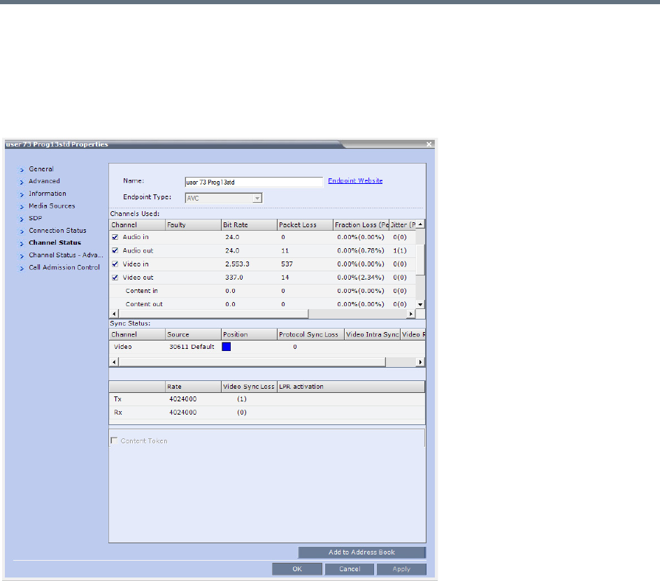
Appendix H - Deployment Into Microsoft Environments
Polycom®, Inc. 993
Monitoring Participant Properties - Channel Status Tab
Two Channel parameters for each Lync 2013 AVMCU Cascade link are displayed: Video in and Video out.
For both Video in and Video out, the Bit Rate and Packet Loss parameters are displayed as aggregate
values. For all other Channel parameters (Jitter, Latency, etc.) the highest values are displayed for each
video stream.
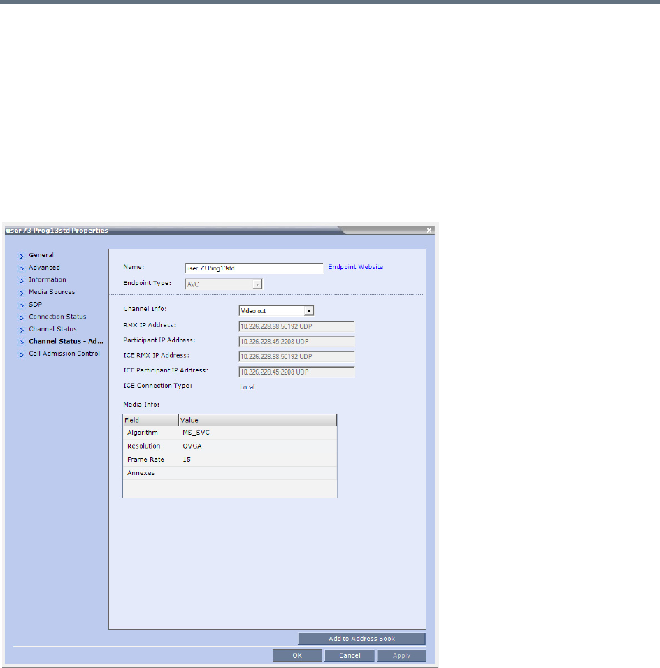
Appendix H - Deployment Into Microsoft Environments
Polycom®, Inc. 994
Monitoring Participant Properties - Channel Status - Advanced Tab
Media Info of each media stream sent by the Lync 2013 AVMCU is displayed:
Stream name: The Display Name of the Lync client.
Algorithms: H.264 or RTV.
Resolution: CIF, SD, VGA, HD720 etc.
Frame Rate: 7.5, 15, 30 etc.
Annexes: Used for H.263 only
RTP Statistics are aggregated and are not detailed per stream.
For more information see Participant Level Monitoring.
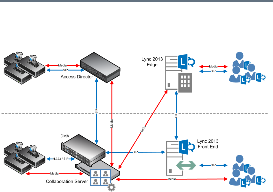
Appendix H - Deployment Into Microsoft Environments
Polycom®, Inc. 995
Deployment Architecture 1 - RealPresence Hosted
Conferences
Lync 2013 clients connect to a conference hosted on a Polycom Collaboration Server.
With this deployment architecture:
●The SVC Codec’s Temporal Scaling capability is used to send one video stream to and from the
Collaboration Server for each resolution at multiple frame rates.
●H.264 SVC uses H.264 SEI messages to send stream layout information rather than SDP messages.
●There is one audio stream per direction.
●Lync clients place calls to a Virtual Meeting Room provisioned on the DMA, for example,
1234@video.domain.com
●The Collaboration Server can connect Lync 2013 participants to either mixed AVC/SVC or to AVC
only conferences.
●Lync 2013 clients dialing to a VMR, where the type of the conference is SVC/AVC mixed and AVC
CP only have their video decoded. The Collaboration Server sends encoded video to Lync 2013
participants.
Look and Feel
All participants experience a Microsoft Point to Point conference with Polycom video layouts.
Only Classic Skin is supported. For more information about Skins, see Defining AVC CP Conferencing
Profiles.
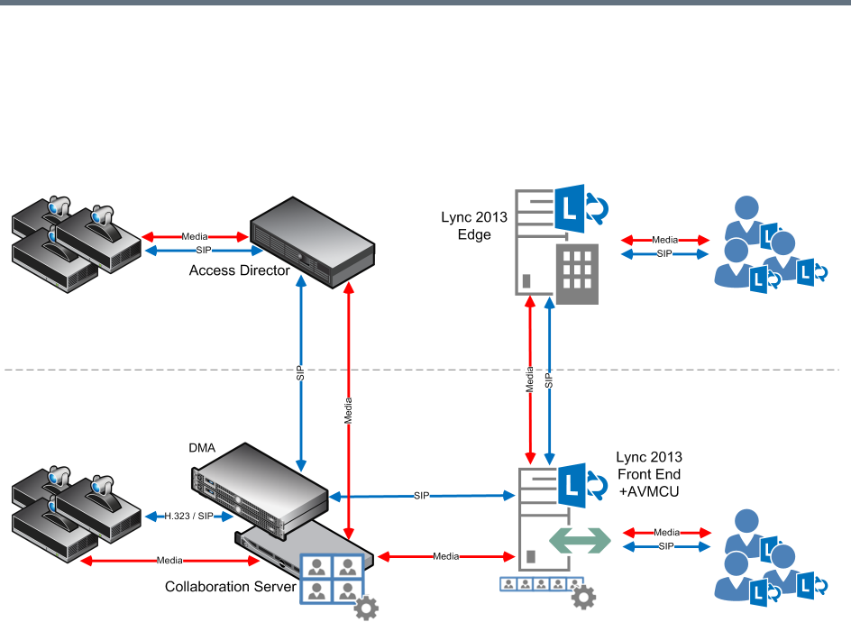
Appendix H - Deployment Into Microsoft Environments
Polycom®, Inc. 996
Deployment Architecture 2 - RealConnect Cascaded
Conferences
Cascaded VMR Participants (Lync 2013 clients) connect to a conference on a Microsoft AVMCU which is
cascaded with a Collaboration Server that is paired with a DMA.
With this deployment architecture, participants connecting to the conference by way of the Collaboration
Server are referred to as Cascaded VMR Participants.
●Lync clients connect to the Lync 2013 AVMCU in either ad hoc or scheduled scenarios.
●The Cascaded VMR connects as a Lync client to the AVMCU.
The Collaboration Server utilizes the SVC Codec’s Temporal Scaling capability to send up to three
simulcast video streams of different resolutions, of the current speaker to the AVMCU.
●The Collaboration Server receives media from up to five different Lync clients from the AVMCU.
●Lync clients experience a Microsoft Point to Point conference with Cascaded VMR Participants
appearing as Lync clients.
●Cascaded VMR Participants experience a conference with Polycom video layouts.
●Lync clients will see the active speaker from the Cascaded VMR while Cascaded VMR Participants
will see up to 5 Lync clients in addition to other participants.
●Lync 2013 clients, connected by means of the Lync AVMCU, in point to point calls, can connect to
Collaboration Server VMR participants by escalating the Lync call to a multipoint conference,
including the Collaboration Server VMR meeting room and its participants.
The Contact List can be used to select participants followed by, right-clicking and selecting Start
a Video Call.
An ad-hoc (Meet Now) Lync conference can be started; a drag-and-drop operation can then be
used in the Contact List to add a Cascaded VMR to the conference.
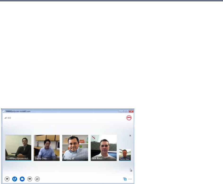
Appendix H - Deployment Into Microsoft Environments
Polycom®, Inc. 997
●Cascaded VMR Participants, in point to point calls, can connect to Lync AVMCU participants by
escalating the call to a multipoint Lync Conference.
A re-INVITE is issued to escalate the conference from point-to-point to multipoint.
●A re-INVITE can be issued from an ongoing Audio conference to escalate it, enabling connected
participants to start sending video.
●Multiple Collaboration Server conferences cannot be cascaded into the same Lync 2013 AVMCU
conference. Multiple concurrent cascades are supported in a 1:1 fashion between simultaneous,
separate conferences.
●The Collaboration Server can host multiple conferences, each connected in cascade to a different
AVMCU hosted conference.
Look and Feel for Lync Clients and Group Series Endpoints
Lync clients and Group Series endpoints with native Lync capability connect to the AVMCU directly and
experience a Lync look and feel conference and can see all Lync clients; up to 5 simultaneously in Gallery
View.
If the active speaker is a Cascaded VMR Participant, the participant is seen by Lync Clients in a video
window in the Gallery View.
By default, Cascaded VMR Participants are forced to a 1x1 layout by the default setting of the
FORCE_1X1_LAYOUT_ON_CASCADED_LINK_CONNECTION System Flag. The flag’s default setting is
YES, which prevents a VMR layout being displayed within a Gallery View video window. If required,
alternative Personal Layouts can be forced only after this System Flag has been added and its value set to
NO.
For more information see, Modifying System Flags.
Look and Feel for Legacy Endpoints
Legacy endpoints will connect to the Collaboration Server and will be able to see all Lync clients; up to 5
simultaneously in Polycom video layouts. Only Classic Skin is supported. For more information about Skins,
see Defining AVC CP Conferencing Profiles.
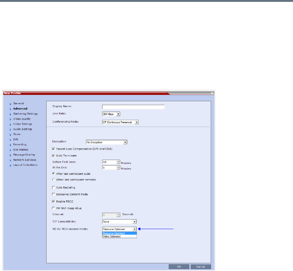
Appendix H - Deployment Into Microsoft Environments
Polycom®, Inc. 998
Video Resource Requirement Selection in Lync 2013 AVMCU Cascade
Collaboration Server resource usage in Lync 2013 AVMCU Cascade can be configured in the Advanced tab
of the Profile dialog by selecting either Resource Optimized or Video Optimized.
Resource Optimized
Resolutions of up to HD540p30 (SD30) are supported, depending on the conference’s profile setting.
Video Optimized
Resolutions of up to HD720p30 are supported, depending on the conference’s profile setting.
If the Collaboration Server has insufficient resources, endpoints will be connected at the lowest resolutions
possible: CIF or SD. If the Collaboration Server has no available resources, endpoints will not be connected.
Calls that are initially connected as Audio Only will only have video resources allocated to them should they
be escalated to video calls.

Appendix H - Deployment Into Microsoft Environments
Polycom®, Inc. 999
Video Forcing and Changing Layout in Lync 2013 AVMCU Cascade
Lync 2013 AVMCU Cascade behaves in the same manner as Collaboration Server to Collaboration Server
Cascading.
The Conference Layout as well as the Personal Layouts of participants can be changed. Participants can
be forced to appear in specific video cells of the layouts.
If Lync 2013 video streams are to be included in a Polycom Conference Layout, the Collaboration Server
will remove these streams from the layout sent over the AVMCU cascade link.
If Lync 2013 video streams are to be included in a Personal Conference Layout, the Collaboration Server
will not remove these streams from the layout to be sent over the AVMCU cascade link.
Handle Low Bit Rate Calls From the AVMCU
If the Collaboration Server or a Group Series endpoint is connected to the AVMCU at a bit rate of 256kbps,
the AVMCU transmits only one video stream even if it receives multiple video source requests.
At bit rates lower than256kbps (128kbps and 192kbps) the AVMCU does not transmit video.
This limitation can be controlled using the DISABLE_LYNC_AV_MCU_128_AND_192_KBPS System Flag.
The flag must be manually added to the System Configuration and its value modified as required:
NO (Default)—The Collaboration Server sends 128kbps or 192kbps (according to the call rate) but
will receive 256kbps for each incoming video stream.
YES—The Collaboration Server will not send or receive video from the Lync AVMCU. The connection
is audio only.
For more information see, Modifying System Flags.
Remove Empty Cells From the Video Layout
Empty cells in the Video Layout can occur as result of the following causes:
Case 1 — A camera connected to a PC that is hosting a Lync client is switched off, the cell in which the Lync
client was displayed remains in the video layout and is empty.
Case 2 — A Lync 2013 Client is connected using a CIF port at a bit rate that exceeds 192kbps.
Case 1
The empty cell can be removed from the video layout by adding the
REMOVE_EP_FROM_LAYOUT_ON_NO_VIDEO_TIMER System Flag and setting its value as required.
Range:
●0 – 19 (seconds): The feature is disabled.
●20 – 300 (seconds): The feature is enabled.
Default: 20
When enabled (flag value 20 - 300), the endpoint is removed when the empty cell is detected, and the cell
is used for another participant if:
●No video RTP messages are received from the EP for the defined timer value in addition to one of
the following timers, depending on the call type:
DETECT_SIP_EP_DISCONNECT_TIMER
DETECT_H323_EP_DISCONNECT_TIMER

Appendix H - Deployment Into Microsoft Environments
Polycom®, Inc. 1000
●Either the PRESERVE_PARTY_CELL_ON_FORCE_LAYOUT System Flag = NO
or
The endpoint is not forced in the layout.
Case 2
The RTV_MAX_BIT_RATE_FOR_FORCE_CIF_PARTICIPANT System Flag has been added to the system
with a default value of 192 (kbps). This ensures that the Lync Client sends the correct resolution and that
its cell in the Video Layout is displayed correctly.
In Lync environments that do not include ICE, the empty cell will remain in the layout for direct Lync
calls.

Appendix H - Deployment Into Microsoft Environments
Polycom®, Inc. 1001
Initiate and Connect to a Conference
There are several methods that Lync clients can use to initiate, and connect to, conferences running in an
environment that contains both Microsoft’s AVMCU and Polycom’s Realpresence Collaboration Servers.
This section discusses:
●Meet Now Lync Conferences
●RealConnect for Microsoft Lync (Requires DMA in the network infrastructure)
Meet Now Lync Conference
When using this method an ad hoc (Meet Now) Lync conference is started by the Lync client. A
Collaboration Server Meeting Room is then dragged and dropped into the conference from the Contact List.
This option requires that both the MCU and the AVMCU reside on the same network subnet, so that no
firewall or other barriers will trigger the NAT Traversal functionality.
To connect to an AVMCU conference:
1Click Meet Now on the Lync menu bar, click or click the arrow next to the Options button and select
Meet Now to start an ad-hoc conference.
2When the Group Conversation dialog box is displayed, drag the Meeting Room from the Lync
client Contacts List into the Group Conversation list.
After the Meeting Room is connected on Lync, an invitation is sent from the AVMCU to the
Collaboration Server using the Centralized Conference Control Protocol (CCCP). The Collaboration
Server responds triggering a standard SIP invite from the AVMCU to the Collaboration Server.
Multiple participants can now connect to both the Collaboration Server Meeting Room and the
AVMCU, and participate in a cascaded conference.
RealConnect for Lync 2013
RealConnect for Microsoft Lync requires that a conference call be scheduled and that Lync clients receive
an Online Meeting invite containing the dial-in conferencing ID.
To connect to a scheduled Online Meeting:
»Click the Join Lync Meeting link in the Online Meeting invite.
A call to the AVMCU is initiated. The RealPresence Platform obtains the Lync conference SIP URI is
obtained. The SIP URI is used to create an ad hoc Virtual Meeting Room (VMR) which is assigned
the same number as the Lync conference ID. The VMR then dials into the Online Meeting and
connects as a Lync Client.
When a conference begins as Audio Only, a Lync user cannot add video to the conference after the
VMR is connected to the conference. The conference will remain Audio Only.

Appendix H - Deployment Into Microsoft Environments
Polycom®, Inc. 1002
Call Admission Control
Call Admission Control (CAC) can be enabled if the RealPresence Collaboration Server system is
configured with a Microsoft Edge Server. Call Admission Control (CAC) is enabled by manually adding the
flags to the system Configuration and setting their values as follows:
●To enable the Call Admission Control implementation in the Collaboration Server:
CAC_ENABLE=YES
●In addition, to ensure that endpoints such as HDX remain connected to the conference for its duration
when the Collaboration Server is configured with FQDN address and the Lync server is working with
load balancing and holds more than one address, the following two flags must be manually added
and set to:
MS_KEEP_ALIVE_ENABLE = YES
Note: Since the Keep Alive is only required when the Lync server is working with load balancing
and holds more than one address, the default value is NO.
SIP_TCP_PORT_ADDR_STRATEGY = 0
●When Call Admission Control is enabled in the local network, by default the local the ICE channel is
closed after applying CAC bandwidth management.
To change and preserve the ICE channel open throughout the call:
PRESERVE_ICE_CHANNEL_IN_CASE_OF_LOCAL_MODE=YES.
Conferencing Behavior
Continuous Presence Conferences
In Continuous Presence conference, Lync clients connect with any allocated bandwidth.
Video Switching Conferences
In Video Switching conferences, Lync clients must connect with the same line rate as the conference,
otherwise they will be connected as Secondary (Audio Only) participants.
Mitigation of the line rate requirement can be effected by modifying the system flag:
VSW_RATE_TOLERANCE_PERECENT.
This system flag determines the line rate tolerance.
Possible values are: 0 - 75.
Setting this flag to 0 (0% - default) determines no line rate tolerance and the participant must connect at the
conference line rate.
Setting this flag to a value between 1 and 75 determines the percentage of bandwidth that can be deducted
from the required bandwidth to allow participants to connect to the conference.
For example, if you enter 20 (for 20%) as the flag value, the participant will be able to connect to the
conference if the allocated line rate is up to 20% lower than the conference line rate (or between 80% and
100% of the required bandwidth). If the conference line rate is 1024Kbps, participant with a line rate between
819Kbps and 1024Kbps will be able to connect to the conference.
When a Tolerance is set, the Highest Common mechanism is enabled for the conference line rate. When a
participant with a lower line rate connects to the conference, the line rates of all other connected participants
are reduced accordingly. When the participant with the low line rate disconnects from the conference, the
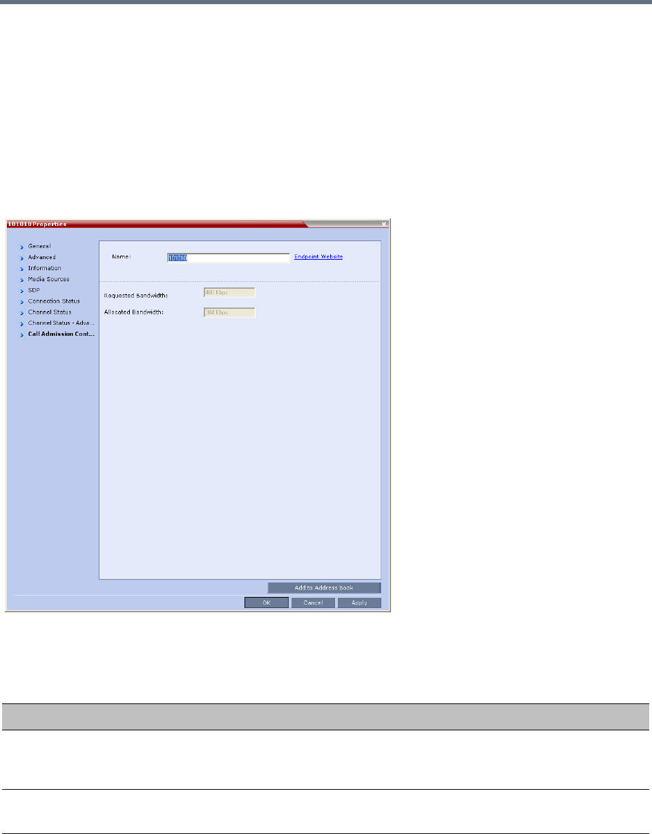
Appendix H - Deployment Into Microsoft Environments
Polycom®, Inc. 1003
line rates of the remaining participants are increased to the highest possible rate common to all connected
participants.
For example, if a participant with a line rate of 900Kbps connects to a conference in which all other
participants are connected at a line rate of 1024Kbps; the line rate of all participants will decrease to
900Kbps. When this participant disconnects, the line rate of the remaining participants will increase to
1024Kbps.
Monitoring Participant Connections
Activation of the Call Admission Control for a call can be viewed in the Participant Properties - Call
Admission Control dialog box.
This information applies only to dial-in participants.
The following information is available:
Participant Properties - Call Admission Control Parameters
Field Description
Requested Bandwidth Indicates the bandwidth requested by the Lync client (usually the line rate set
for the conference).
NA - indicates that Call Admission Control is disabled.
Allocated Bandwidth The actual bandwidth allocated by the Lync Policy Server.
NA - indicates that Call Admission Control is disabled.

Appendix H - Deployment Into Microsoft Environments
Polycom®, Inc. 1004
Active Alarms and Troubleshooting
Active Alarms
The following active alarms may be displayed in the Collaboration Server System Alerts pane when the
Collaboration Server is configured for integration in the OCS environment:
Active Alarms
Alarm Code Alarm Description
SIP TLS: Failed to load or verify
certificate files
This alarm indicates that the certificate files required for SIP TLS could not
be loaded to the Collaboration Server. Possible causes are:
•Incorrect certificate file name. Only files with the following names can be
loaded to the system: rootCA.pem, pkey.pem, cert.pem and
certPassword.txt
•Wrong certificate file type. Only files of the following types can be loaded
to the system: rootCA.pem, pkey.pem and cert.pem and
certPassword.txt
•The contents of the certificate file does not match the system
parameters
SIP TLS: Registration transport error This alarm indicates that the communication with the SIP server cannot be
established. Possible causes are:
•Incorrect IP address of the SIP server
•The SIP server listening port is other than the one defined in the system
•The OCS services are stopped
Note:
Sometimes this alarm may be activated without real cause. Resetting the
MCU may clear the alarm.
SIP TLS: Registration handshake
failure
This alarm indicates a mismatch between the security protocols of the
OCS and the Collaboration Server, preventing the Registration of the
Collaboration Server to the OCS.
SIP TLS: Registration server not
responding
This alarm is displayed when the Collaboration Server does not receive a
response from the OCS to the registration request in the expected time
frame. Possible causes are:
•The Collaboration Server FQDN name is not defined in the OCS pool,
or is defined incorrectly.
•The time frame for the expected response was too short and it will be
updated with the next data refresh. The alarm may be cleared
automatically the next time the data is refreshed.
Alternatively, the OCS Pool Service can be stopped and restarted to
refresh the data.
•The Collaboration Server FQDN name is not defined in the DNS server.
Ping the DNS using the Collaboration Server FQDN name to ensure
that the Collaboration Server is correctly registered to the DNS.
SIP TLS: Certificate has expired The current TLS certificate files have expired and must be replaced with
new files.

Appendix H - Deployment Into Microsoft Environments
Polycom®, Inc. 1005
ICE Active Alarms
When ICE environment is enabled in the Collaboration Server, failure to communicate with a required
component triggers the display of an Active Alarm in the System Alerts pane.
The following table lists these active alarms:
SIP TLS: Certificate is about to expire The current TLS certificate files will expire shortly and will have to be
replaced to ensure the communication with the OCS.
SIP TLS: Certificate subject name is
not valid or DNS failed to resolve this
name
This alarm is displayed if the name of the Collaboration Server in the
certificate file is different from the FQDN name defined in the OCS.
Note:
Occasionally this alarm may be activated without real cause. Resetting the
MCU may clear the alarm.
ICE Environment - Collaboration Server Active Alarms
Active Alarm Phase Alarm Displayed When Troubleshooting
ICE failure: Failed to
register with OCS.
Check the
Collaboration Server’s
Server Name.
Registration The Collaboration Server did
not receive a confirmation
response from the OCS to the
Registration request.
•Check that the Collaboration
Server Name in IP Network
Service - SIP Advanced is
identical to the User name
defined for the Collaboration
Server in the OCS Active
Directory.
•Make sure that the Collaboration
Server user is defined in the OCS
Active Directory.
ICE failure: Failed to
subscribe with the
OCS, therefore the A/V
Edge Server URI was
not received.
Subscribe The Collaboration Server did
not receive a confirmation
response from the OCS to the
Subscription request.
The Subscription is required
for obtaining the A/V Edge
Server URI which is followed
by the notify message
containing the credentials).
ICE failure: The Notify
message containing the
A/V Edge Server URI
was not received
Notify The Notify message
containing the A/V Edge
Server URI was not received
by the Collaboration Server.
ICE failure: Received
Notification does not
contain URI.
Notify The notify message that was
sent from the A/V Edge Server
does not contain the A/V Edge
server URI.
Verify the A/V Edge server is
configured in the OCS.
Active Alarms
Alarm Code Alarm Description
Appendix H - Deployment Into Microsoft Environments
Polycom®, Inc. 1006
Troubleshooting
●At the end of the installation and configuration process, to test the solution and the integration with
the OCS, create an ongoing conference with two participants, one dial-in and one dial-out and
connect them to the conference.
●If the active Alarm SIP TLS: Registration server not responding is displayed, stop and
restart the OCS Pool Service.
●If the communication between the OCS and the Collaboration Server cannot be established, one of
the possible causes can be that the Collaboration Server FQDN name is defined differently in the
DNS, OCS and Collaboration Server. The name must be defined identically in all three devices, and
defined as type A in the DNS. You can test the definition of the Collaboration Server FQDN name in
the DNS by pinging it, and receiving the Collaboration Server’s signaling IP from the DNS in the
response.
●The communication between the OCS and the Collaboration Server can be checked in the Logger
files:
SIP 401/407 reject messages indicate that the Collaboration Server is not configured as Trusted
in the OCS and must be configured accordingly.
SIP 404 reject indication indicates that the connection to the OCS was established successfully.
Known Issues
●Selecting Pause my Video in the OC Client causes the call to downgrade to Audio Only if the call was
not originally an Audio Only call (the call was started as a video call).
If the call is started as an Audio Only call and video is added to it, or if the call was started as a video
call and during the call it was changed to Audio Only and then back to video, selecting Pause my
Video will suspend it as required.
ICE failure: No
response from the A/V
Edge Server to the
Collaboration Server
Service Request
Service The Collaboration Server did
not receive a confirmation
response from the A/V Edge
Server to the Service request.
ICE failure: Received
Service message does
not contain the
Credentials.
Service The Service message
response does not contain the
Credentials.
ICE failure:
A/V Edge server URI
cannot be resolved
Service The Collaboration Server
failed to resolve The remote
address of the Edge server
URI.
ICE failure: Service
credential denied. A/V
Edge server credentials
rejected by the OCS.
Service This alarm indicates that the
OCS does not configure with
the credentials.
Generated by the ICE stack.
ICE Environment - Collaboration Server Active Alarms
Active Alarm Phase Alarm Displayed When Troubleshooting

Appendix H - Deployment Into Microsoft Environments
Polycom®, Inc. 1007
●Rarely, the OC Client disconnects after 15 minutes. The OC Client can be reconnected using the
same dialing method in which they were previously connected (dial-in or dial-out).
●Rarely, all SIP endpoints disconnect at the same time. The SIP endpoint can be reconnected using
the same dialing method in which they were previously connected (dial-in or dial-out).

Polycom®, Inc. 1008
Appendix I - Polycom Open
Collaboration Network (POCN)
Collaboration With Cisco’s Telepresence
Interoperability Protocol (TIP)
TIP is a proprietary protocol created by Cisco for deployment in Cisco TelePresence systems (CTS). Since
TIP is not compatible with standard video communication systems, interoperability between Cisco and other
vendors’ Telepresence systems was initially impossible.
Gateways were developed to provide interoperability but were subject to the inherent problems of additional
latency (delay) in connections and low video quality resulting from the reformatting of video and audio
content.
Polycom’s solution is to allow the Collaboration Server to natively inter-operate with Cisco TelePresence
Systems, ensuring optimum quality multi-screen, multipoint calls between:
●Polycom Immersive Telepresence Systems (ITP) Version 3.1.1:
RPX 200
RPX 400
OTX 300
(At Telepresence Licence is required on the Collaboration Server.)
●Polycom video conferencing endpoints
Standalone HDX
Polycom Group Series 300/500
●Microsoft
MS Lync (using MS-ICE)
RTV 720p
●Cisco TelePresence® System (CTS) Versions 1.10 Collaboration Server
CTS 1300
CTS 3010
Conferences hosted on the Collaboration Server can include a mix of existing end points (that do not
support TIP) and CTS endpoints.
TIP-enabled endpoints must support TIP Version 7 or higher. Calls from endpoints supporting older versions
of TIP will be rejected.
Working in the Open Collaboration Server and TIP protocol are supported in AVC Conferencing Mode
only.
Although Cisco legacy endpoints are inter-operable with Collaboration Server (RMX) 1800-0, the
MCU is not supported for integration into third-party and partner environments.

Appendix I - Polycom Open Collaboration Network (POCN)
Polycom®, Inc. 1009
Deployment Architectures
The following multipoint topologies are given as examples. Actual deployments will depend on user
requirements and available infrastructure:
●Single company with Polycom and Cisco Infrastructure
CTS and Polycom Telepresence Rooms in a corporate environment.
●Company to company via Service Provider
Model 1: Mixed Polycom and Cisco infrastructure at one of the companies, Cisco only
infrastructure at the other.
Model 2: Polycom only infrastructure at one of the companies, Cisco only infrastructure at the
other.
Single Company Model - Polycom and Cisco Infrastructure
The deployment architecture in Single company with Polycom and Cisco Infrastructure - Polycom endpoints
using SIP shows a company that has a mixture of Polycom and Cisco endpoints, room systems and
telephony equipment that needs to enable multipoint calls between all its video and audio endpoints using
the Collaboration Server as the conference bridge.
As shown in Single company with Polycom and Cisco Infrastructure - Polycom endpoints using SIP, Cisco
Telepresence endpoints can connect to conferences using the TIP protocol, Polycom endpoints connected
to the same conferences using SIP protocol.
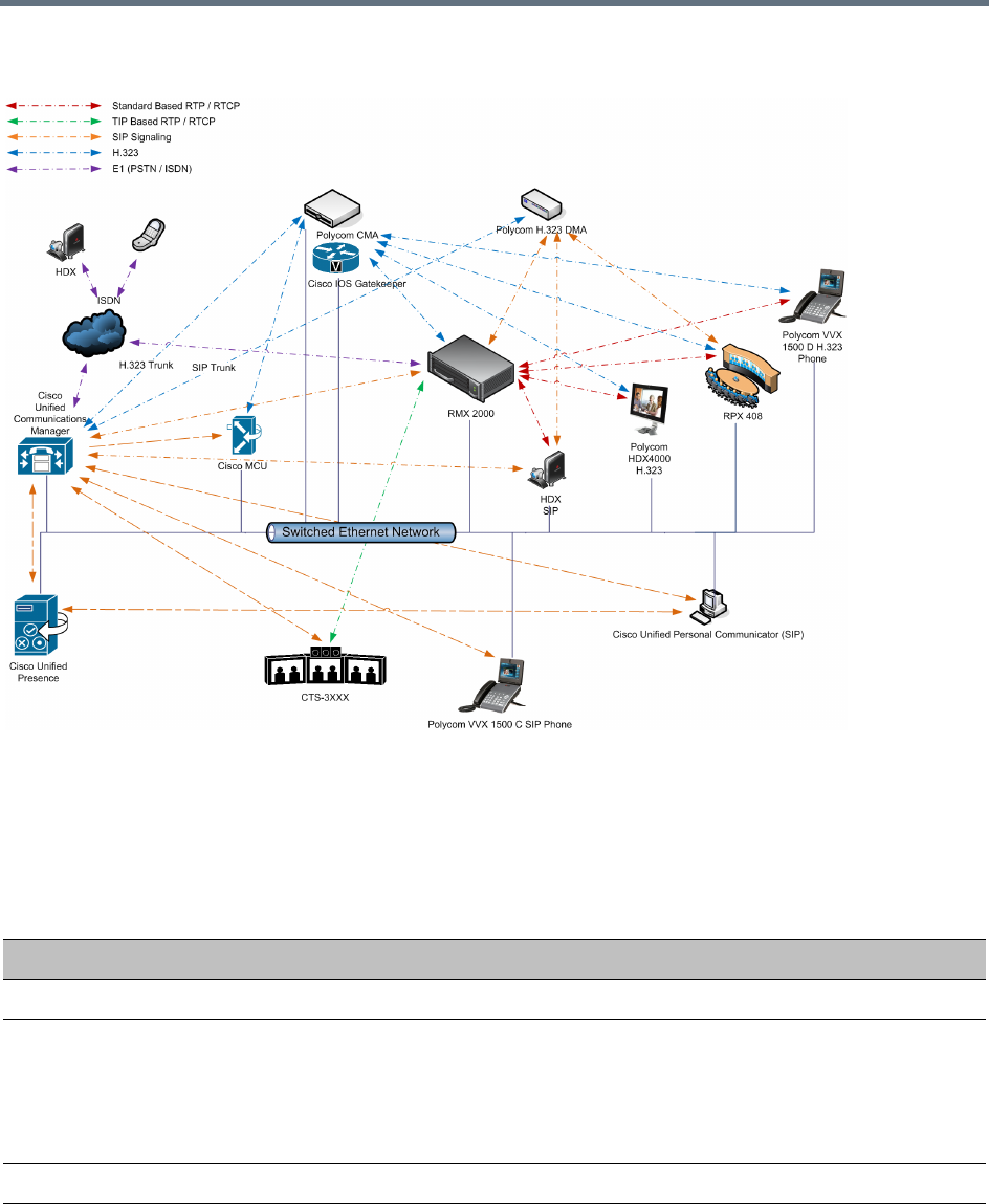
Appendix I - Polycom Open Collaboration Network (POCN)
Polycom®, Inc. 1010
Single company with Polycom and Cisco Infrastructure - Polycom endpoints using SIP
Polycom endpoints can also connect to Entry Queues, Meeting Rooms and conferences using all protocols,
including TIP and SIP.
The following table lists components and versions of the Collaboration Server and Cisco Telepresence
Systems (CTS) Integration Solution Architecture.
Solution Architecture Components
Component Version Description
CISCO Equipment
CUCM 8.5.1, 8.6.2 Cisco Unified Communication Manager:
CUCM must be configured to:
•Route calls to DMA (if present).
•Route all H.323 calls to the IOS gatekeeper, which can be either
DMA or IOS.
IOS 15.1T Cisco Internetwork Operating System - Gatekeeper
Endpoints (CTS) 1.7.2 (ATT),
1.8.1
Telephony, desktop and room systems.
•CTS endpoints must register to CUCM.
Appendix I - Polycom Open Collaboration Network (POCN)
Polycom®, Inc. 1011
Cisco Unified Video
Conferencing 5230
7.2 MCU.
Cisco Unified
Presence
8.5, 8.6 Network-based Presence and Instant Messaging.
Cisco Unified
Contact Center
Express
8.0, 8.5 Call distributor (ACD), interactive voice
response (IVR) and computer telephony integration (CTI).
Cisco IP
Communicator
7.0,8.6 Windows PC-based softphone application.
Cisco Unified
Personal
Communicator
8.5(2),8.5(5) Web client for Presence and Instant Messaging.
Cisco Unified Video
Advantage
2.2(2) Video telephony functionality for Cisco Unified IP phones.
Cisco Unified IP
Phones 7960, 7961,
7962, 7965, 7975
CUCM 8.5.1 /
CUCM 8.6.1
compatible
IP Phones.
Cisco Unified IP
Phones 9971
CUCM 8.5 /
CUCM 8.6(2)
compatible
CTMS 1.7.3, 1.8.2 Cisco TelePresence Multipoint Switch.
Cisco Unified Border
Element
15.1T SBC - Voice and video connectivity from enterprise IP network to
Service Provider SIP trunks.
Telepresence Server 2.2(1.54) Telepresence Server.
VCS X7.1 Video Communication Server / Session Manager.
Polycom Equipment
DMA 7000 4.0 Polycom Distributed Media Application
•DMA is an optional component but is essential if Content sharing is
to be enabled.
•All SIP endpoints register to DMA as a SIP Proxy.
•DMA should be configured to route SIP calls (with CTS destination)
to CUCM. If DMA is not present in the solution architecture, SIP
endpoints must register to CUCM as gatekeeper.
•DMA must be configured with a VMR (Virtual Meeting Room).
Incoming calls are then routed to the Collaboration Server.
Solution Architecture Components
Component Version Description
Appendix I - Polycom Open Collaboration Network (POCN)
Polycom®, Inc. 1012
Collaboration Server 7.6 and higher MCU:
•Functions as the network bridge for multipoint calls between H.323,
SIP and TIP endpoints.
•The Collaboration Server can be interfaced to CUCM using a SIP
trunk, enabling CTS to join multipoint calls on Collaboration Server.
Signaling goes through the CUCM while the media in TIP format
goes directly between the CTS and Collaboration Server.
•The Collaboration Server must be configured to route outbound SIP
calls to the DMA.
•The H.323 Network Service of the Collaboration Server should
register it's dial prefix with the DMA gatekeeper.
•When the DMA is not used an Ad-hoc Entry Queue, designated as
Transit Entry Queue, must be pre-defined on the Collaboration
Server.
MLA 3.0.3 Multipoint Layout Application
Required for managing multi-screen endpoint layouts for Cisco CTS
3XXX, Polycom TPX, RPX or OTX systems.
Endpoints Telephony, desktop and room systems.
•H.323 endpoints must register to the IOS gatekeeper.
•Polycom SIP endpoints must register to DMA as SIP Proxy when
DMA is used.
•H.323 endpoints must register to the IOS gatekeeper.
Solution Architecture Components
Component Version Description
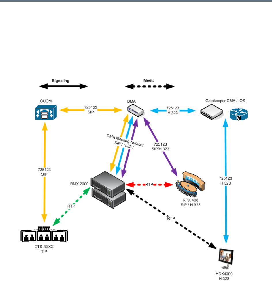
Appendix I - Polycom Open Collaboration Network (POCN)
Polycom®, Inc. 1013
Call Flows
Multipoint call with DMA
In this example:
●Collaboration Server prefix in the gatekeeper: 72
●Virtual Meeting Room in DMA: 725123
●DMA Meeting Number: Generated by DMA
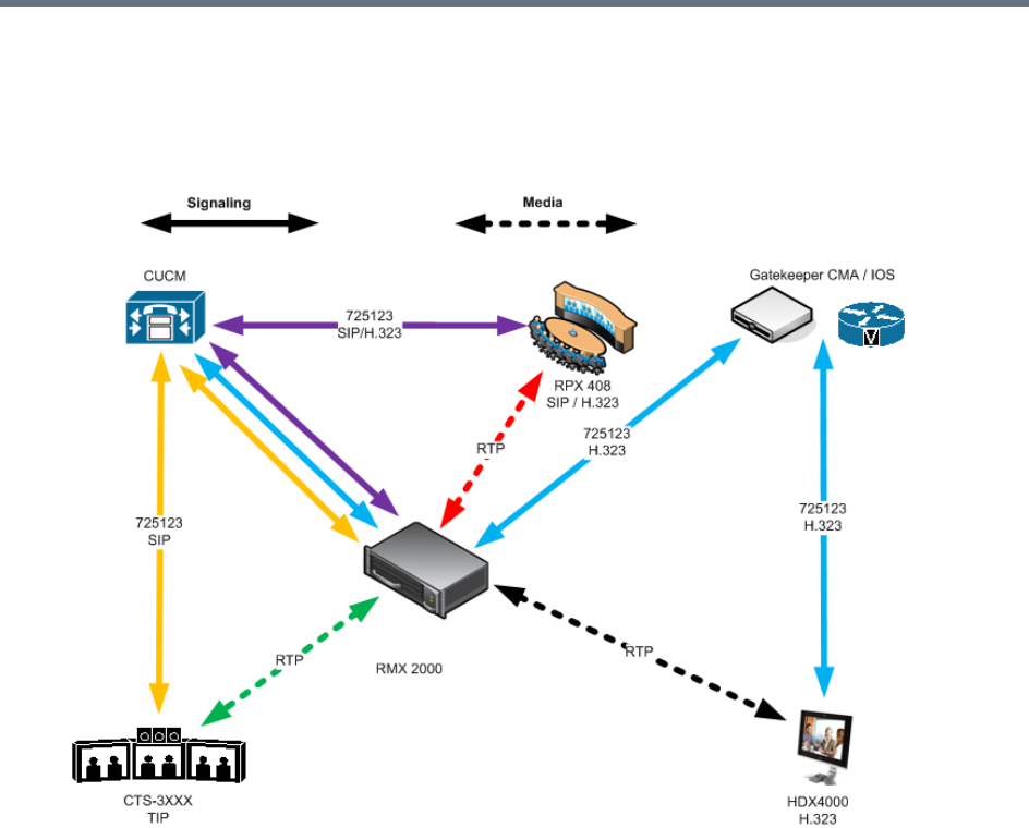
Appendix I - Polycom Open Collaboration Network (POCN)
Polycom®, Inc. 1014
Multipoint call without DMA
In this example:
●Collaboration Server prefix in the gatekeeper: 72
●CUCM: According to its Dial Plan forwards calls with prefix 72 to the Collaboration Server

Appendix I - Polycom Open Collaboration Network (POCN)
Polycom®, Inc. 1015
Company to Company Models Using a Service Provider
Using this topology, both companies connect to a Service Provider via a Cisco Session Border Controller
(SBC). The Service Provider functions as a B2B Telepresence Exchange, enabling multipoint calls between
the two companies and their respective video and audio endpoints using the Collaboration Server as the
conference bridge.
The SBC functions as a firewall that the Service Provider can configure according to Trust Relationships
between two or several companies. By using this method, companies do not have to open their corporate
firewalls and administer connectivity with the many companies they may need to communicate with.
Two topology models are discussed:
●Model 1:
Company A has a Polycom only environment.
Company B has a Cisco only Environment.
●Model 2:
Company A has a mixed Polycom and Cisco environment.
Company B has a Cisco only Environment.
Model 1
The deployment architecture in Call Flow shows two companies: Company A and Company B.
Company A - has deployed a Polycom solution including:
●DMA
●Collaboration Server
●MLA
●Polycom telephony and desktop endpoints.
Company B - has deployed a Cisco solution including:
●CTS 1000
●CTS 3000
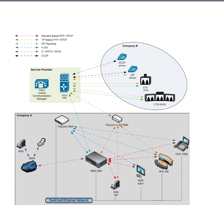
Appendix I - Polycom Open Collaboration Network (POCN)
Polycom®, Inc. 1016
●Cisco telephony and desktop endpoints
Company to Company via Service Provider - Model 1
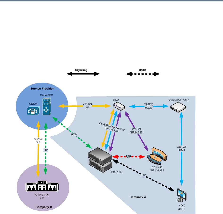
Appendix I - Polycom Open Collaboration Network (POCN)
Polycom®, Inc. 1017
Call Flow
Multipoint call via Service Provider - Model 1
In this example:
●Collaboration Server prefix in the gatekeeper: 72
●Virtual Meeting Room in DMA: 725123
●DMA Meeting Number: Generated by DMA
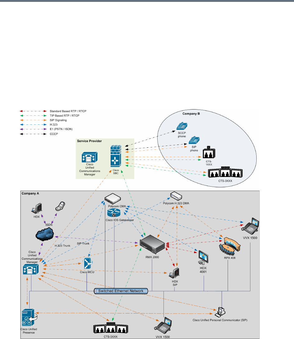
Appendix I - Polycom Open Collaboration Network (POCN)
Polycom®, Inc. 1018
Multipoint call via Service Provider - Model 2
The deployment architecture in The deployment architecture includes: shows two companies: Company A
and Company B.
Company A - has the same deployment architecture as shown in Single Company Model - Polycom and
Cisco Infrastructure.
Company B - has deployed a Cisco solution including:
●CTS 1000
●CTS 3000
●Cisco telephony endpoints.
Appendix I - Polycom Open Collaboration Network (POCN)
Polycom®, Inc. 1019
The deployment architecture includes:
Company A
For a full description of Company A’s deployment, see Single Company Model - Polycom and Cisco
Infrastructure.
Differing or additional configuration requirements for each element of this deployment model are listed
below:
Company B
Company A Solution Architecture Components
Component Version Description
CISCO Equipment
CUCM 8.5 Cisco Unified Communication Manager:
CUCM must be configured with a SIP trunk to the Service Provider’s
SBC.
Polycom Equipment
Collaboration Server 7.6.x and up MCU:
Collaboration Server must be configured to send and receive RTP
streams to and from the Service Provider's SBC.
Company B Solution Architecture Components
CISCO Equipment
Endpoints Endpoints should register with the Service Provider’s CUCM (or the
local CUCM, if present).
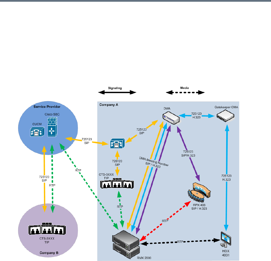
Appendix I - Polycom Open Collaboration Network (POCN)
Polycom®, Inc. 1020
Call Flow
Multipoint call via Service Provider - Model 2
In this example:
●Collaboration Server prefix in the gatekeeper: 72
●Virtual Meeting Room in DMA: 725123
●CUCM: According to its Dial Plan forwards calls with prefix 72 to the Collaboration Server

Appendix I - Polycom Open Collaboration Network (POCN)
Polycom®, Inc. 1021
Administration
The various deployment combinations and settings within the various Deployment Architectures affects the
administration of the system.
Gatekeepers
Standalone Polycom DMA System as a Gatekeeper
The Polycom DMA system can be used as the only gatekeeper for the network. Bandwidth and call
admission control of endpoints registered with the DMA system is split between the DMA and the CUCM.
For more information see the Polycom Unified Communications Deployment Guide for Cisco Environments.
Standalone Cisco IOS Gatekeeper
The Cisco IOS Gatekeeper can be used as the only gatekeeper for the network if the management
capabilities of the Polycom DMA system are not required.
For more information see the Polycom Unified Communications Deployment Guide for Cisco Environments.
Neighbored Cisco IOS and Polycom DMA Gatekeeper
Neighbored gatekeepers make it easier to create a common dial plan and should be considered when
integrating an existing Cisco telephony environment with an existing Polycom network. Neighbored
Gatekeepers allow number translation while maintaining the existing environments.
For more information see the Polycom Unified Communications Deployment Guide for Cisco
Environments,DMA
The Polycom DMA system can be configured as a SIP proxy and registrar for the environment. When used
as a SIP peer, the DMA system can host video calls between Cisco endpoints that are registered with the
CUCM and Polycom SIP endpoints that are registered with the DMA system.
For more information see the Polycom Unified Communications Deployment Guide for Cisco Environments.
CUCM
When Polycom SIP endpoints (voice and video) are registered directly with CUCM you can take advantage
of supported telephone functions. CUCM may not support the full range of codecs and features available
on the Polycom equipment. CUCM supported codecs and features will be used in such cases.
For more information see Polycom Unified Communications Deployment Guide for Cisco Environments.
Configuring the Cisco and Polycom Equipment
MLA (Multipoint Layout Application) is required for managing CTS 3XXX layouts whether Polycom TPX,
RPX or OTX systems are deployed or not. MLA is a Windows® application that allows conference
administrators to configure and control video layouts for multipoint calls involving Polycom Immersive
Telepresence (ITP) systems.
Call Detail Records (CDR) are generated on both the DMA Gatekeeper and the CUCM for reporting and
billing purposes.

Appendix I - Polycom Open Collaboration Network (POCN)
Polycom®, Inc. 1022
Cisco Equipment
To configure the various Cisco entities the following procedures are required.
CUCM
»Configure the CUCM to send and receive calls from the H.323 network.
aWith Neighbored IOS and DMA Gatekeepers
bWith IOS Gatekeeper
For more information see the Polycom Unified Communications Deployment Guide for Cisco
Environments.
IOS Gatekeeper
●Set up zones and gateway type prefixes to enable dialing to DMA and Collaboration Server systems.
IOS and DMA Gatekeepers (Neighbored)
●Configure the Cisco IOS Gatekeeper for two separate zones.
Polycom Equipment
The following table lists the Polycom products supported within the various Deployment Architecture.
Only Collaboration Server configurations are described in detail in this document.
Configuration procedures for all other solution components are described in the Polycom Unified
Communications Deployment Guide for Cisco Environments.
Supported Polycom products
Polycom TIP and SIP Version(s)
Polycom DMA 7000 system V4.0
Polycom RealPresence Collaboration Server (RMX) 2000/4000
systems
V7.6 and higher
Immersive Telepresence Systems:
•RPX 200 and 400 systems
•OTX 300 system
•TPX HD 306 system
•ATX HD 300 system
V3.0.3
Requires TIP option key.
Requires Polycom Touch Control.
HDX Systems:
•7000 HD Rev C
•8000 HD Rev B
•9006
•4500
V3.0.3
Requires TIP option key.
Peripheral Polycom Touch Control 1.3.0
SIP ONLY (no TIP support) Version(s)

Appendix I - Polycom Open Collaboration Network (POCN)
Polycom®, Inc. 1023
The following procedures 1 -16 are a summary of the configuration procedures.
The detailed procedures 1 - 16 begin with Procedure 1: Set the MIN_TIP_COMPATIBILITY_LINE_RATE
System Flag.
Configuring the Collaboration Server
1Set the MIN_TIP_COMPATIBILITY_LINE_RATE System Flag
2Configuring the Collaboration Server to statically route outbound SIP calls to DMA or CUCM
3Configuring the Collaboration Server’s H.323 Network Service to register with DMA gatekeeper
4Configuring a TIP enabled Profile on the Collaboration Server
5Configuring an Ad Hoc Entry Queue on the Collaboration Server if DMA is not used
6Configuring a Meeting Room on the Collaboration Server
7Configuring Participant Properties for dial out calls
Configuring DMA
If DMA is present in the configuration perform procedures Configuring DMA to route SIP calls to CUCM and
Configuring a Virtual Meeting Room (VMR), otherwise skip to procedure Configuring CMA to route H.323
calls to Collaboration Server.
1Configuring DMA to route SIP calls to CUCM
2Configuring a Virtual Meeting Room (VMR)
The procedures for configuring DMA are described in detail in the Polycom Unified Communications
Deployment Guide for Cisco Environments.
Configuring Endpoints
1Configuring H.323 endpoints to register to the IOS gatekeeper
The procedures for configuring H.323 endpoints are described in detail in the Polycom Unified
Communications Deployment Guide for Cisco Environments.
2Configuring SIP endpoints to register to:
aDMA as SIP Proxy
bCUCM as SIP Proxy
The procedures for configuring SIP endpoints are described in detail in the Polycom Unified
Communications Deployment Guide for Cisco Environments.
3Configuring TIP endpoints to register to:
aDMA
Spectralink wireless phones 8020/8030
Polycom VVX 1500 V4.0
Polycom VVX 1500 C V3.3.1
KIRK Wireless Server 300/600v3/6000
Supported Polycom products

Appendix I - Polycom Open Collaboration Network (POCN)
Polycom®, Inc. 1024
bCUCM
The procedures for configuring TIP- enabled endpoints are described in detail in the Polycom Unified
Communications Deployment Guide for Cisco Environments
Configuring Entry Queues and IVR Services
Conference IVR and Entry Queue/Virtual Entry Queues are supported with AVC TIP protocol in conferences
that include both TIP-enabled and non-TIP-enabled endpoints.
A Virtual Entry Queue can be configured to either IVR Only Service Provider or External IVR Control mode.
TIP-enabled endpoints can be moved from the Entry Queue to the destination conference if the TIP
Compatibility Modes settings in the Profile are identical for both conferencing entities (it is recommended to
use the same Profile for both entities).
TIP IVR users can access the conference directly or enter the Entry Queue/Virtual Entry Queue and provide
a password to access the conference.
The IVR services can be enabled with Prefer TIP TIP compatibility mode.
IVR media files, WAV for voice messages and JPG for video slides, are all stored on the Collaboration
Server.
Guidelines
●IVR default audio files are enabled for all TIP Compatibility Modes.
●In order for the MCU to detect DTMF digits from TIP-enabled endpoints, the system flag
SIP_REDUCE_AUDIO_CODECS_DECLARATION must be set to YES.
If the flag is set to NO, the MCU cannot detect DTMF digits from TIP endpoints.
●In an mixed TIP environment there is no support for content in cascaded conferences.
Entry Queue and Virtual Entry Queue Access
TIP endpoints can dial-in to conferences directly using the IVR, Entry Queue/Virtual Entry Queue and IVR
Only Service Provider.
Configuring the Conference and Entry Queue IVR Services
The IVR module includes two types of services:
●Conference IVR Service that is used with conferences
●Entry Queue IVR Service that is used with Entry Queues
The configuration process is the same for TIP and non-TIP enabled Conferences and Entry Queues.
Content
Polycom and Cisco endpoints can share Content within a Cisco TelePresence environment. The content
sharing experience depends on whether the endpoints are registered with the DMA or CUCM.
Appendix I - Polycom Open Collaboration Network (POCN)
Polycom®, Inc. 1025
Endpoint Registration Options - Content Sharing Experience
●H.239
A variety of resolutions and frame rates are supported.
For more information see Content Sharing Using H.239 Protocol and Content Sharing Using
People+Content Protocol.
Can be used with SIP and H.323 endpoints, desktop (CMAD), room systems (HDX) and ITP
(OTX, RPX).
Not supported by Lync clients, IBM clients and Cisco CTS endpoints.
Cannot be used when HDX endpoints are registered to CUCM.
●TIP
The resolution is fixed at XGA at 5fps, 512 Kbps.
Supported on HDX, Polycom ITP and Cisco CTS systems.
●The following content compatibility options are available:
None (TIP not enabled) – TIP endpoints cannot join the conference.
Prefer TIP - Both TIP and non-TIP endpoints can share content via H.264, base profile, using
resolution and rate as described above.
For more information see Procedure 4: Configuring a TIP Enabled Profile on the Collaboration
Server.
Procedure 1: Set the MIN_TIP_COMPATIBILITY_LINE_RATE System Flag
The MIN_TIP_COMPATIBILITY_LINE_RATE System Flag determines the minimum line rate at which an
Entry Queue or Meeting Room can be TIP enabled.
CTS version 1.9.1 is required, and if CUCM is present in the environment, a minimum line rate of 1280 kbps
must be set in the conference profile. Calls at lower line rates are rejected, therefore the System Flag value
must be set to 1280 or higher.
HD Video Resolutions for TIP calls are determined according to the following table:
Multipoint Calls on Collaboration Server Content Sharing People + Content
Endpoints Registered to DMA
HDX/ITP to HDX/ITP Yes Yes
HDX/ITP to Cisco CTS Yes Yes
Cisco CTS to HDX/ITP Yes No
Endpoints Registered to CUCM
HDX/ITP to HDX/ITP Yes No
HDX/ITP to Cisco CTS Yes No
Cisco CTS to HDX/ITP No No
Appendix I - Polycom Open Collaboration Network (POCN)
Polycom®, Inc. 1026
For more information see Modifying System Flags.
Procedure 2: Configuring Collaboration Server to statically route outbound SIP
calls to DMA or CUCM
1In the IP Network Services Properties dialog box, click the SIP Servers tab.
2In the SIP Server field, select Specify.
3In the SIP Server Type field, select Generic.
4Set Refresh Registration to every 3600 seconds.
5If not selected by default, change the Transport Type to TCP.
6In the SIP Servers table:
aEnter the IP address of the DMA or CUCM in both the Server IP Address or Name and Server
Domain Name fields.
bThe Port field must be set to it’s default value: 5060. DMA and CUCM use this port number by
default.
7In the Outbound Proxy Servers table:
aEnter the IP address in the Server IP Address or Name field. (The same value as entered in Step
6a.)
bThe Port field must be set to it’s default value: 5060.
(By default, the Outbound Proxy Server is the same as the SIP Server.)
TIP HD Video Resolution by Line Rate
Line Rate Video Resolution
Line Rate >=3Mbps HD1080p30
3Mbps > Line Rate >= 936kbps HD720p30
Line Rate < 936kbps Call is dropped.
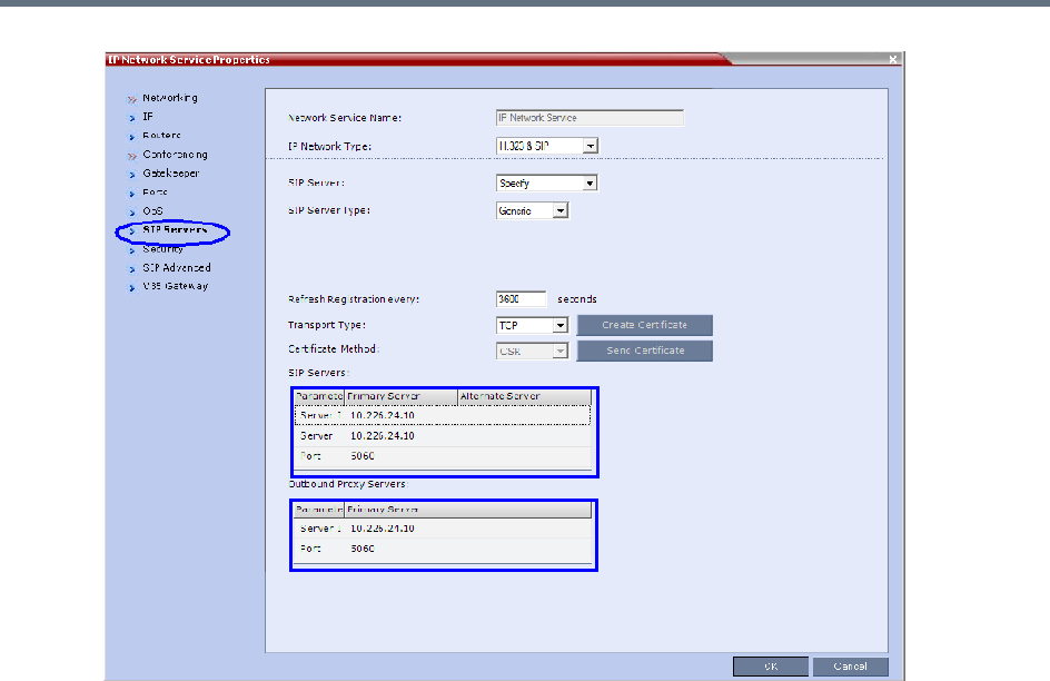
Appendix I - Polycom Open Collaboration Network (POCN)
Polycom®, Inc. 1027
When configuring Collaboration Server to statically route SIP calls to DMA or CUCM, it is important
to also configure the Collaboration Server’s H.323 Network Service to register with DMA gatekeeper.
For more information see Procedure 3: Configuring the Collaboration Server’s H.323 Network
Service to register with DMA gatekeeper.
Procedure 3: Configuring the Collaboration Server’s H.323 Network Service to
register with DMA gatekeeper
1In the IP Network Services Properties dialog box, click the Gatekeeper tab.
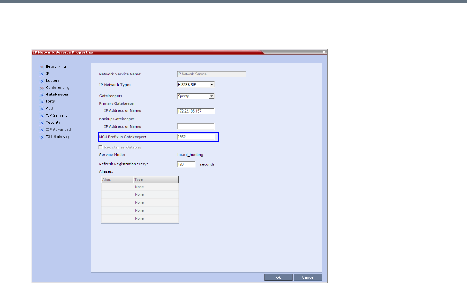
Appendix I - Polycom Open Collaboration Network (POCN)
Polycom®, Inc. 1028
2In the MCU Prefix in Gatekeeper field, enter the prefix that the Collaboration Server uses to register
with the gatekeeper.
Procedure 4: Configuring a TIP Enabled Profile on the Collaboration Server
TIP enabled profiles must be used for the Entry Queues and Meeting Rooms defined on the Collaboration
Server. (Different Profiles can be assigned to Entry Queues and Meeting Rooms, however they must be TIP
enabled.) When TIP is enabled in the Profile, Gathering Settings and Message Overlay options are
disabled.
1Create a New Profile for the Meeting Room.
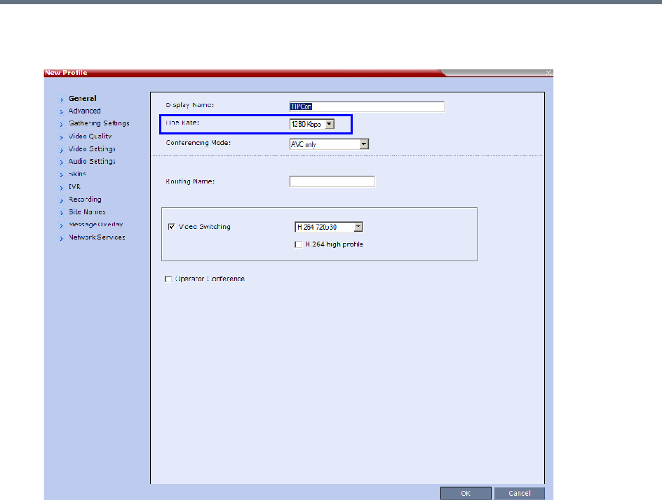
Appendix I - Polycom Open Collaboration Network (POCN)
Polycom®, Inc. 1029
2In the New Profile - General tab, set the Line Rate to a value of at least that specified for the
MIN_TIP_COMPATIBILITY_LINE_RATE System Flag in Procedure 1.
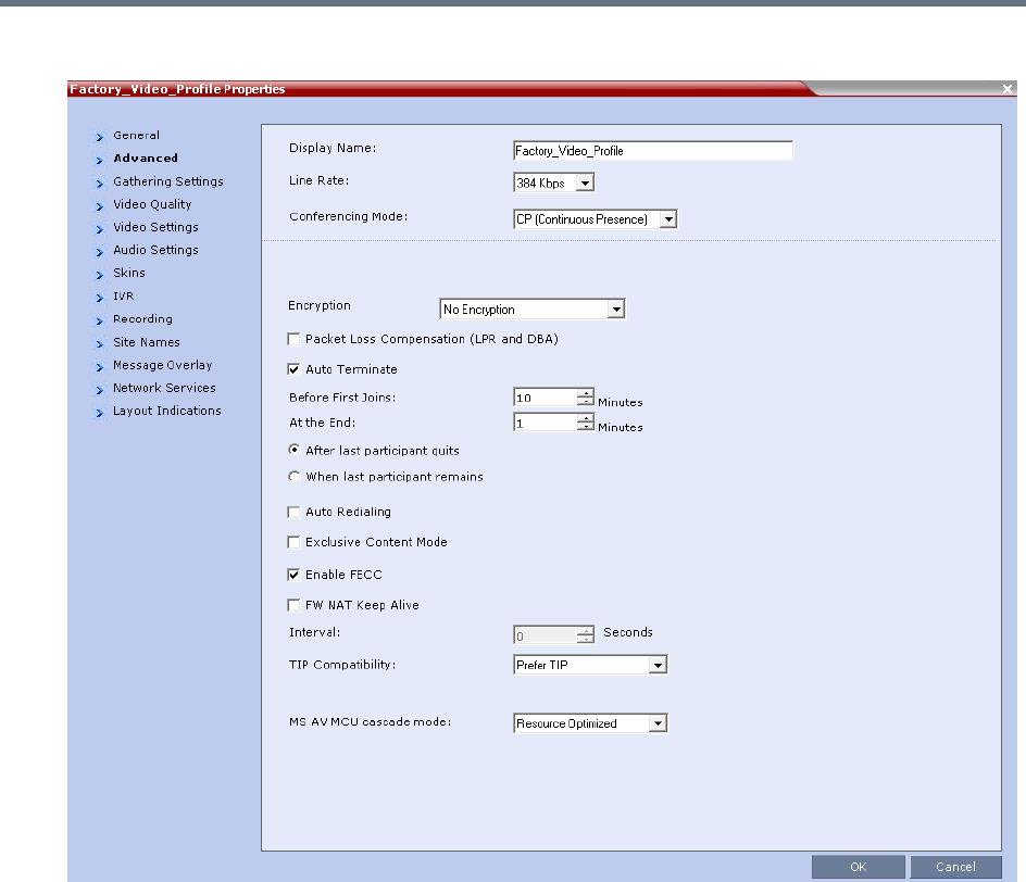
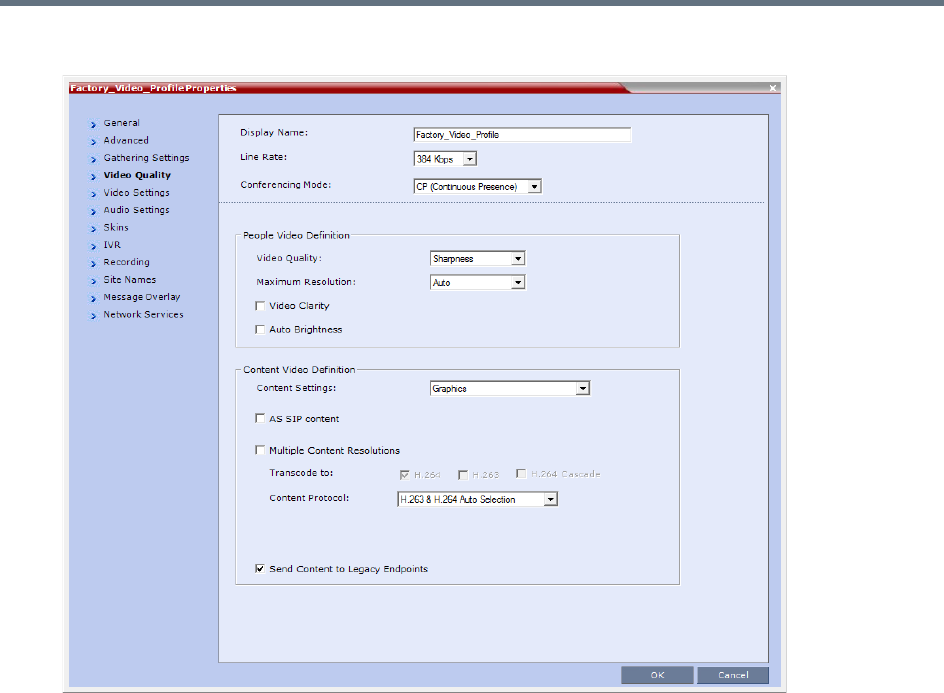
Appendix I - Polycom Open Collaboration Network (POCN)
Polycom®, Inc. 1031
5Click the Video Quality tab.
Content Settings is disabled if TIP Compatibility is set to Prefer TIP in the Advanced tab.
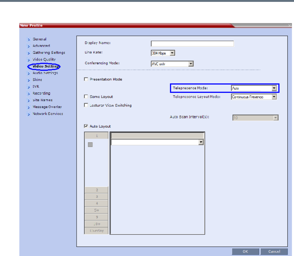

Appendix I - Polycom Open Collaboration Network (POCN)
Polycom®, Inc. 1033
Content Sharing Behavior
The following tables list the system’s Content sharing behavior for the various combinations of TIP
Compatibility mode settings and the following endpoints:
Polycom Immersive Telepresence Systems (ITP) Version 3.0.3:
RPX 200
RPX 400
OTX 300
TPX HD 306
ATX HD 300
Polycom video conferencing endpoints (HDX) Version 3.0.3:
7000 HD Rev C
8000 HD Rev B
9006
4500
Cisco TelePresence® System (CTS) Versions 1.7 / 1.8:
CTS 1000
CTS 3000
* CTS Version 1.9.1 and higher support H.264 Content.
TIP Compatibility - None
None
Content Receiver
HDX / ITP CTS
Content
Sender
HDX / ITP
Media:
Flow Control:
H.264
H.323 via H.239
SIP via BFCP
Not Connected
CTS Not Connected Not Connected
TIP Compatibility - Prefer TIP
Prefer TIP
Content Receiver
HDX / ITP CTS
Content
Sender
HDX / ITP Media:
Flow Control:
H.264
H.323 via H.239
SIP via BFCP
TIP via Auto Collaboration
CTS*
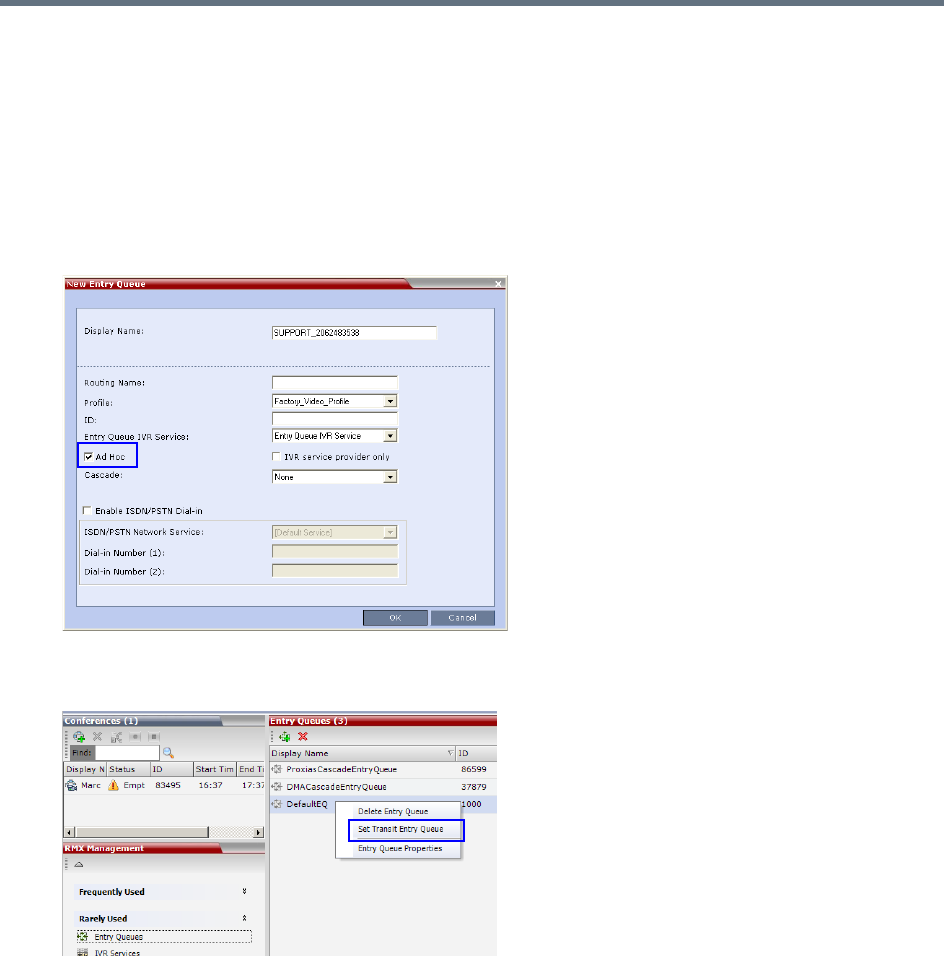
Appendix I - Polycom Open Collaboration Network (POCN)
Polycom®, Inc. 1034
In Prefer TIP mode, it is pre-requisite that the CTS and CUCM versions support H.264 base profile
content without restrictions and that the CTS version be 1.9.1 or higher and that CUCM version be
version 9.0 or higher.
Procedure 5: Configuring an Ad Hoc Entry Queue on the Collaboration Server if
DMA is not used
1Create or select the Entry Queue as described in Entry Queues.
2In the New Entry Queue or Entry Queue Properties dialog box, ensure that Ad Hoc is selected.
3Ensure that the Entry Queue is designated as the Transit Entry Queue as described in Setting a
Transit Entry Queue.
Procedure 6: Configuring a Meeting Room on the Collaboration Server
The Profile for the Meeting Room must be TIP enabled as described in Procedure 4.
For more information see Creating a New Meeting Room.
Procedure 7: Configuring Participant Properties for dial out calls
Participant Properties must be configured to ensure that defined participants inherit their TIP settings from
the Profile assigned to the Meeting Room.
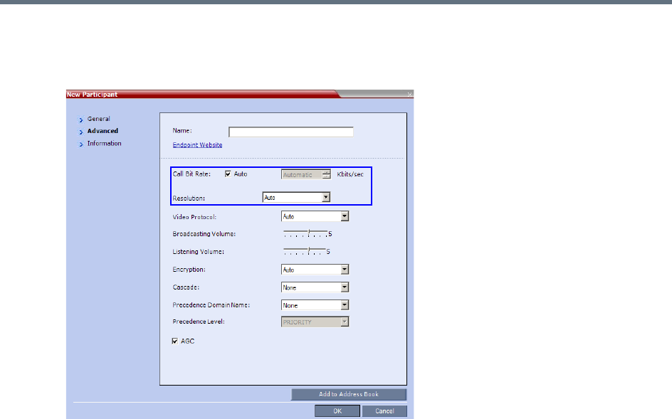
Appendix I - Polycom Open Collaboration Network (POCN)
Polycom®, Inc. 1035
aDefine the New Participant - General settings. For more information see Adding a Participant to
the Address Book.
bClick the Advanced tab.
cEnsure that:
Call Bit Rate is set to Automatic or at least equal to or greater than the value specified by the
MIN_TIP_COMPATIBILITY_LINE_RATE System Flag.
Resolution is set to Auto or at least HD 720.
Video Protocol is set to Auto or at least H.264.
Collaboration with Microsoft and Cisco
This solution enables Polycom, Microsoft and Cisco users, each within their own environment, to participate
in the same conference running on an Collaboration Server.
The Collaboration Server natively inter-operates with Microsoft Lync and Cisco TelePresence Systems,
ensuring optimum quality multi-screen, multipoint calls between:
●Polycom Immersive Telepresence Systems (ITP) Version 3.1.1:
RPX 200
RPX 400
OTX 300
●Polycom video conferencing endpoints
Standalone HDX
Polycom Group Series 300/500
●Microsoft
MS Lync (using MS-ICE)

Appendix I - Polycom Open Collaboration Network (POCN)
Polycom®, Inc. 1036
RTV 720p
●Cisco TelePresence® System (CTS) Versions 1.10
CTS 1300
CTS 3010
The deployment architecture in Single company with Polycom and Cisco Infrastructure - Polycom endpoints
using SIP shows a company that has a mixture of Polycom, Cisco and Microsoft endpoints, room systems
and telephony equipment that needs to enable multipoint calls between all its video and audio endpoints
using the Collaboration Server as the conference bridge.
This solution enables Polycom, Microsoft and Cisco users, each within their own environment, to participate
in the same conference running on an MCU.
In the solution described in Single company with Polycom and Cisco Infrastructure - Polycom endpoints
using SIP:
●DMA is required as all calls are dial-in to Virtual Meeting Rooms (VMR) provisioned on the DMA.
●Microsoft and Cisco clients dial the same VMR number to connect to the conference.
●Dial- out calls directly from the RMX are not supported.
●Lync Clients cannot share content with CTS
●SIP trunks are required to the DMA from:
MS Lync as a Static Route.
CUCM
Deployment Architecture:
●DMA is required as all calls are dial-in to Virtual Meeting Rooms (VMR) provisioned on the DMA.
●Microsoft and Cisco clients dial the same VMR number to connect to the conference.
●Dial- out calls are not supported
●Lync Clients can not share content with CTS
●SIP trunks are required to the DMA from:
MS Lync as a Static Route.
CUCM
For more information, see Cisco TIP Support.
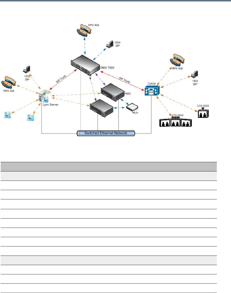
Appendix I - Polycom Open Collaboration Network (POCN)
Polycom®, Inc. 1037
POCN Polycom, Microsoft and Cisco Infrastructure. Solution Architecture
components
.
POCN Polycom, Microsoft and Cisco Infrastructure. Solution Architecture components
Component Version
Polycom
HDX 3.0.5
RSS 8.5.1
RealPresence Capture Server 1.7
DMA 5.0
CMAD 5.2.3
ITP (OTX, RPX, ATX, TPX) 3.0.5
Conferencing for Outlook (PCO) 1.0.7
Touch Control 1.3
Microsoft
Microsoft Lync 2010 Server 4.0.7577.223(CU10)
Microsoft Lync 2013 Server 5.0.8308.556 (CU3)
Microsoft Lync 2010 client 4.0.7577.4051 CU4
Exchange 2007 R2 SP3 8.3.213.1
Appendix I - Polycom Open Collaboration Network (POCN)
Polycom®, Inc. 1038
The following are not supported:
●In the Lync environment:
Sending or receiving Content.
Dial-out to Lync clients.
Presence of VMRs
●In the Cisco environment:
TLS and SRTP
OBTP
Exchange 2010 SP2 14.2.247.5
Outlook 2007 12.0.6557.5001 SP2
Outlook 2010 14.0.6112.5000
Cisco
CUCM 8.5, 8.6.2
Cisco Unified Personal communicator 8.5(2),8.5(5)
Cisco Unified IP Phones 7960, 7961, 7962, 7965, 7975 CUCM 8.5 / CUCM 8.6(2) Compatible
CTS 1.7.4, 1.8.1
C90, C20 TC5.0
POCN Polycom, Microsoft and Cisco Infrastructure. Solution Architecture components
Component Version
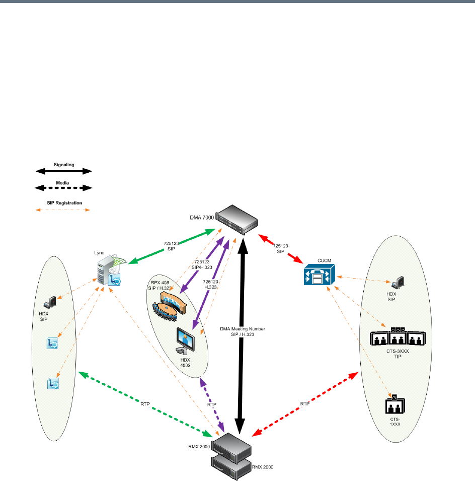
Appendix I - Polycom Open Collaboration Network (POCN)
Polycom®, Inc. 1039
Call Flow
Multipoint Calls using DMA
In this example:
●Endpoint registration: To either DMA, Lync or CUCM.
●DMA dial in Prefix: 72
●Virtual Meeting Room in DMA: 725123
●DMA Meeting Number: Generated by DMA

Appendix I - Polycom Open Collaboration Network (POCN)
Polycom®, Inc. 1040
Administration
The various deployment combinations and settings within the Deployment Architecture affects the
administration of the system.
DMA
The DMA system can be configured as a SIP proxy and registrar for the environment as well as a
Gatekeeper for dial in H.323 calls. When configured as a Gateway for dial in H.323 calls, it enables H.323
endpoints to connect to the same VMR as SIP clients.
When used as a SIP peer, the DMA system can host video calls between Cisco endpoints that are registered
with the CUCM, Lync Clients that are registered with the Lync Server and Polycom endpoints that are
registered with the DMA system.
For more information see Using a Polycom DMA System as SIP Peer in the Polycom Unified
Communications Deployment Guide for Cisco Environments.
Microsoft Lync Server
Microsoft Lync Server manages Presence for each registered Polycom endpoint and enables video calls
between Lync Clients and Polycom endpoints allowing Lync contacts to be called without needing to know
their addresses.
RTV video, MS-ICE and Lync-hosted conferencing are supported when Polycom endpoints are registered
to Lync Server. Polycom endpoints use H.264, while Lync Clients use the RTV protocol.
CUCM
When Polycom SIP endpoints (voice and video) are registered directly with CUCM you can take advantage
of supported telephone functions. CUCM may not support the full range of codecs and features available
on the Polycom equipment. CUCM supported codecs and features will be used in such cases.
For more information see Direct Registration of Polycom Endpoints with the Cisco Unified Communications
Manager Participants in the Polycom Unified Communications Deployment Guide for Cisco Environments.
Solution Interoperability Table
The following table lists components and versions of the Collaboration Server, Microsoft and Cisco
Telepresence Systems (CTS) Integration Solution Architecture.
Solution Architecture Components
Component Version Description
CISCO Equipment
CUCM 9.0.1 Cisco Unified Communication Manager:
•CUCM must be configured to route calls to ASR/SBC. CUCM must be
configured with a SIP trunk to the Service Provider’s SBC.
•All endpoints must register once with the CUCM
•SIP trunks from CUCM to Polycom system components (eg. DMA) should
be configured with Music on Hold disabled.

Appendix I - Polycom Open Collaboration Network (POCN)
Polycom®, Inc. 1041
ASR (Cisco SBC) 100x The Cisco Aggregation Services Routers (ASR) Series includes Cisco IOS
XE Software Internetwork Operating System - Gatekeeper.
It controls and manages real-time multimedia traffic flows between IP/SIP
network borders, handling signaling, data, voice, and video traffic.
Polycom Equipment
DMA 6.0.0_ATT_B
uild_25
Polycom Distributed Media Application
•DMA is an optional component but is essential if Content sharing is to be
enabled.
•All SIP endpoints register to DMA as a SIP Proxy.
•DMA should be configured to route SIP calls (with CTS destination) to
CUCM.
•DMA can be configured with a VMR (Virtual Meeting Room). Incoming
calls are then routed to the Collaboration Server.
Collaboration
Server
8.1.1 and up MCU:
•Functions as the network bridge for multipoint calls between H.323, SIP
and TIP endpoints.
•The Collaboration Server can be interfaced to CUCM using a SIP trunk,
enabling CTS to join multipoint calls on Collaboration Server. Signaling
goes through the CUCM while the media in TIP format goes directly
between the CTS and Collaboration Server.
•The Collaboration Server must be configured to route outbound SIP calls
to DMA.
•Collaboration Server must be configured to send and receive RTP
streams to and from the Service Provider's SBC.
MLA Server 3.0.5 Multipoint Layout Application
Required for managing multi-screen endpoint layouts for Cisco CTS 3XXX,
Polycom TPX, RPX or OTX systems.
HDX and ITP
Endpoints
3.1.1.1 Telepresence, desktop and room systems.
•Polycom SIP endpoints must register to DMA as SIP Proxy.
Microsoft
Lync 2010 4.0.7577.183
CU4
Lync 2010 client 4.0.7577.405
1 CU4
Exchange 2007
R2 SP3
8.3.213.1
Exchange 2010
SP2
14.2.247.5
Solution Architecture Components
Component Version Description

Appendix I - Polycom Open Collaboration Network (POCN)
Polycom®, Inc. 1042
TIP Layout Support & Resource Usage
Cisco Telepresence endpoints using TIP protocol support only one (CTS 1000) or three (CTS 3000) display
screens. Therefore, Polycom Telepresence endpoints will adjust their display to use one or three screens
as follows:
●OTX system - Works with three screens, therefore no adjustment is required and it should be set to
work in room switch Telepresence Layout Mode (while avoiding zooming in/out)
●RPX 2xx - This endpoint works with two screens, therefore it will adjust to use only one screen.
●RPX 4xx - This endpoint works with four screens, therefore it will adjust to use only three screens.
●Standalone HDX - behaves as the CTS 1000 and uses only one screen.
●Group system 300/500 - behaves as the CTS 1000 and uses only one screen.
The Polycom MLA Server manages the conference template layouts for Telepresence systems.
The number of screens used by each TIP-enabled endpoint is determined during the capabilities exchange
phase of the dial-in connection. It affects the usage and allocation of resources used with TIP-enabled
endpoints.
Supported TIP Resolutions and Resource Allocation
Supported Resolutions
In Telepresence TIP-enabled environment, only two video resolutions are available: 720p30 and 1080p30.
Resource Allocation
The MCU media processor (ART) supports up to three TIP-enabled screens as follows:
●One TIP-enabled endpoint with three screens
●Up to three TIP-enabled endpoint with one screen
Outlook 2007 12.0.6557.50
01 SP2
Outlook 2010 14.0.6112.50
00
Supported resolution per conference line rate
Conference Line Rate Selected Resolution
3Mb or higher 1080p 30 fps
963kbps to 3Mb 720p 30 fps
Up to 936kbps Call is disconnected.
Solution Architecture Components
Component Version Description
Appendix I - Polycom Open Collaboration Network (POCN)
Polycom®, Inc. 1043
TIP-enabled endpoint with three screens must be handled by the same media processor. This endpoint may
fail to connect if there is no one fully free media (ART) processor available.
The MCU will always try to fill up one media processor with up to three TIP-enabled endpoint with one
screen, to save free media processors for TIP-enabled endpoint with three screens.
When monitoring an ongoing Telepresence conference with TIP-enabled endpoints (Cisco and Polycom),
virtual participants are used to indicate the additional screens in the in the Web Client. For example, if the
endpoint has three screens, the system will display three participants, one for each screen.
An additional virtual Audio Only participant is used for the audio only telephone connected to the TIP
endpoint.
System capacity per MPMx card and resolution is summarized in the following table:
Configuring the Microsoft, Cisco and Polycom
Components
Carry out the following steps to configure the various system components to enable TIP.
To configure the Microsoft, Cisco and Polycom components:
1Configure a SIP Trunk connection between the Polycom DMA system and the Cisco Unified
Communications Manager (CUCM).
For more information see the Polycom Unified Communications Deployment Guide for Cisco
Environments
2Register the Collaboration Server to the Lync Server
aInstall a Security Certificate on the Collaboration Server.
The Certificate is obtained from the System Administrator and saved on the Workstation.
bIn the SIP Servers tab of the IP Network Services Properties dialog box:
1In the Certificate Method drop-down menu, select PEM/PFX.
2Click the Send Certificate button.
The Install File dialog box is displayed.
MPMx Resolution Capacities
No. of media processors
(ART) per card
No. of TIP screens per
media processor 720p30 ports 1080p30 ports
10 3 30 15
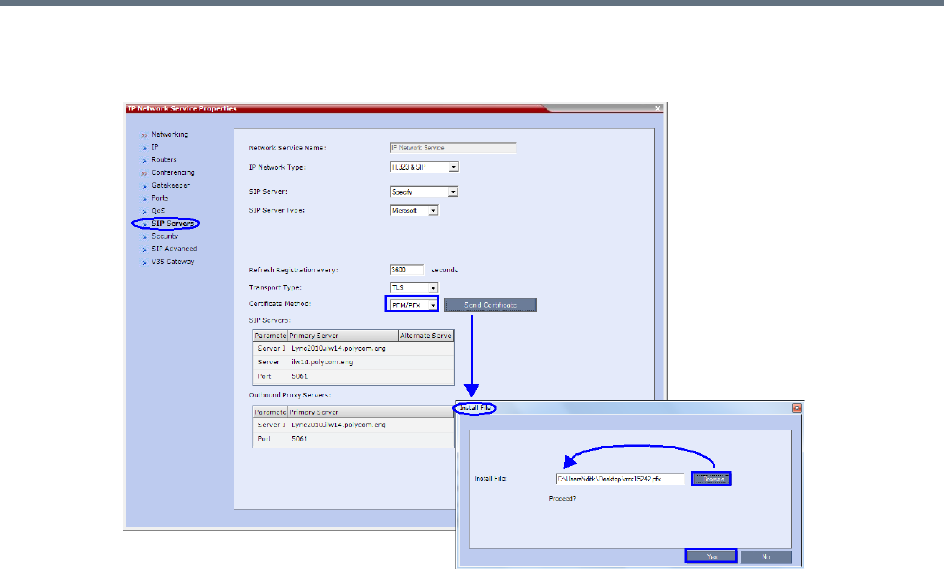
Appendix I - Polycom Open Collaboration Network (POCN)
Polycom®, Inc. 1044
iii Browse to the saved Certificate on the Workstation and click the Yes button to install the
certificate.
For more information see:
Appendix H - Integration Into Microsoft Environments.
The Polycom Unified Communications Deployment Guide for Cisco Environments.
3Register the Collaboration Server with the Lync Server.
aIn the IP Network Services Properties dialog box, click the SIP Servers tab.
bIn the SIP Server field, select Specify.
cIn the SIP Server Type field, select Microsoft.
dSet Refresh Registration to every 3600 seconds.
eIf not selected by default, change the Transport Type to TLS.
fIn the SIP Servers table, enter the IP address of the Lync Server in both the Server IP Address
or Name and Server Domain Name fields.
gIn the SIP Servers table, the Port field must be set to 5061.
hIn the Outbound Proxy Servers table, enter the IP address in the Server IP Address or Name
field. (The same value as entered in Step f.)
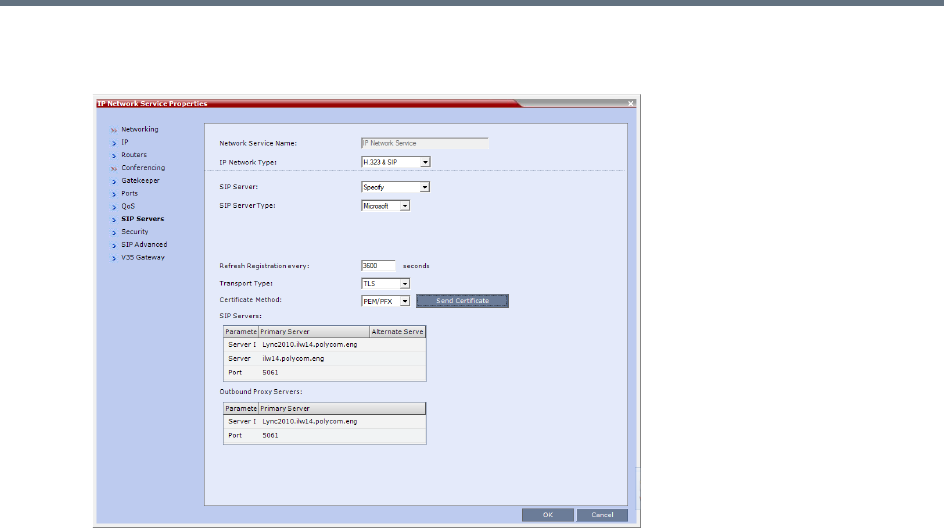
Appendix I - Polycom Open Collaboration Network (POCN)
Polycom®, Inc. 1045
iIn the Outbound Proxy Servers table, the Port field must be set to 5061. (The same value as
entered in Step g.)
For more information see the Polycom Unified Communications Deployment Guide for Cisco
Environments
4Set the ITP_CERTIFICATION System Flag to YES.
When set to NO (default), this flag disables the Telepresence features in the Conference Profile.
5Set the MIN_TIP_COMPATIBILITY_LINE_RATE System Flag.
The MIN_TIP_COMPATIBILITY_LINE_RATE System Flag determines the minimum line rate at
which a Profile can be TIP enabled.
CTS version 1.7 requires a minimum line rate of 1024 kbps and will reject calls at lower line rates,
therefore the System Flag value must be 1024 or higher.
6If required, manually add and set the FORCE_720P_2048_FOR_PLCM_TIP System Flag using
one of the following values:
FORCE_720P_2048_FOR_PLCM_TIP (Default) - Forces HD 720p video resolution and a line rate
of 2048kbps for all Polycom TIP-enabled endpoints that connect to the TIP-enabled Telepresence
conference. This setting is the recommended setting.
FORCE_2048_FOR_PLCM_TIP - Forces a line rate of 2048kbps for all Polycom TIP-enabled
endpoints connecting to the TIP-enabled Telepresence conference.
NO_FORCE - No forcing is applied and Polycom TIP-enabled endpoints can connect to the
TIP-enabled Telepresence conference at any line rate or resolution.
7Reset the Collaboration Server.
8Register the DMA to the Lync server
For more information see the Polycom Unified Communications Deployment Guide for Cisco
Environments
9Register the ITP endpoints to the Lync server.

Appendix I - Polycom Open Collaboration Network (POCN)
Polycom®, Inc. 1046
10 Register Lync Clients to the Lync server.
For more information see the relevant Lync documentation.
11 Register DMA to the CUCUM server
12 Register CTS1000 and CTS3000 endpoints to the CUCUM server
For more information see the relevant Cisco documentation.
13 Register ITP endpoints to the CUCM server.
14 Register HDX endpoints to the DMA as Gatekeeper
15 Open MLA to configure ITP Layouts
MLA (Multipoint Layout Application) is required for managing CTS 3XXX layouts whether Polycom
TPX, RPX or OTX systems are deployed or not. MLA is a Windows® application that allows
conference administrators to configure and control video layouts for multipoint calls involving
Polycom Immersive Telepresence (ITP) systems.
For more information see the Polycom Unified Communications Deployment Guide for Cisco
Environments.
16 Configure a TIP Enabled Profile on the Collaboration Server.
aCreate a New Profile for the Meeting Room.
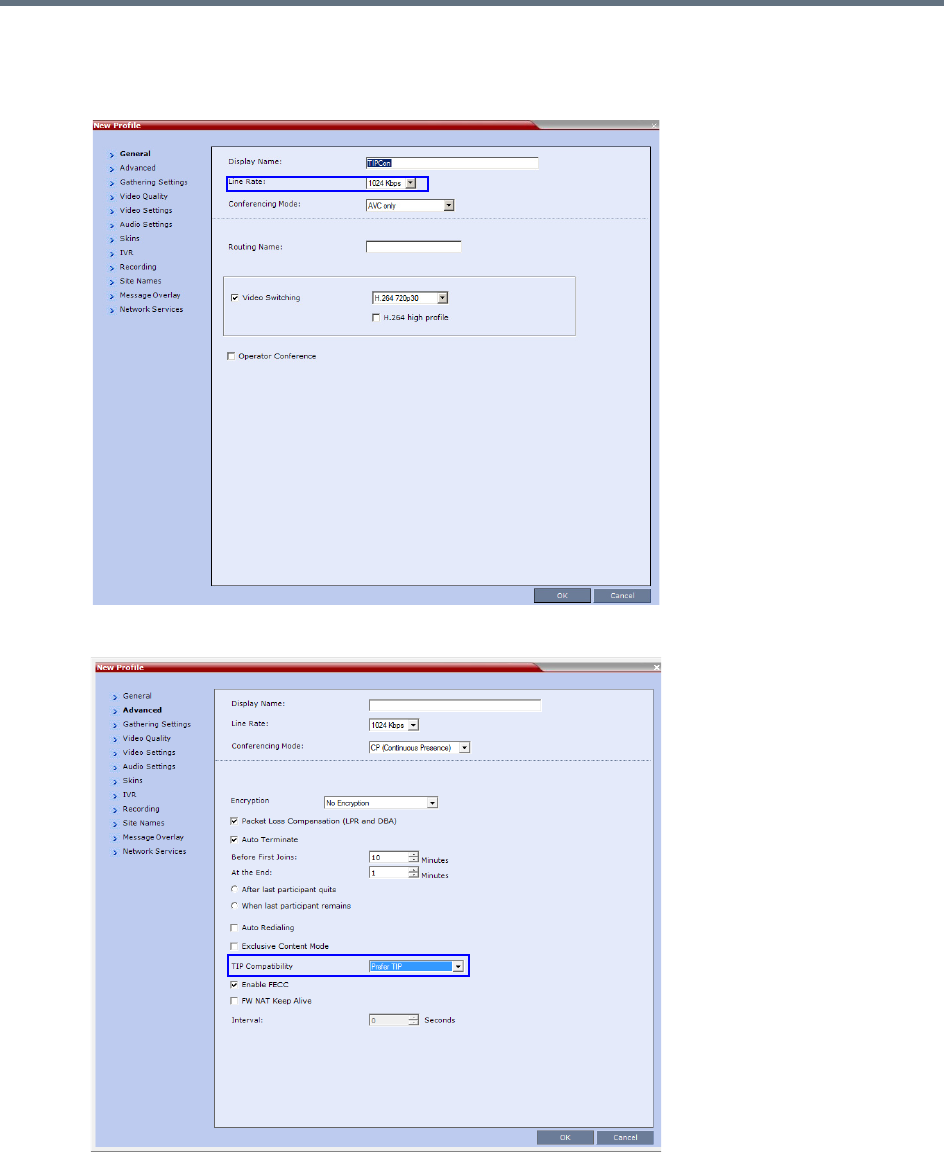
Appendix I - Polycom Open Collaboration Network (POCN)
Polycom®, Inc. 1047
bIn the New Profile - General tab, set the Line Rate to a value of at least that specified for the
MIN_TIP_COMPATIBILITY_LINE_RATE System Flag in Procedure 1: Set the
MIN_TIP_COMPATIBILITY_LINE_RATE System Flag.
cClick the Advanced tab.
dSelect Prefer TIP as the TIP Compatibility mode. To view its behavior, see the Content Sharing
Behavior tables that are listed below.

Appendix I - Polycom Open Collaboration Network (POCN)
Polycom®, Inc. 1048
Content Sharing Behavior
The following tables list the system’s Content sharing behavior for the various combinations of TIP
Compatibility mode settings and the following endpoints:
Polycom Immersive Telepresence Systems (ITP) Version 3.0.3:
RPX 200
RPX 400
OTX 300
TPX HD 306
ATX HD 300
Polycom video conferencing endpoints (HDX) Version 3.0.3:
7000 HD Rev C
8000 HD Rev B
9006
4500
Cisco TelePresence® System (CTS) Versions 1.7 / 1.8:
CTS 1000
CTS 3000
When Prefer TIP is selected, Video Switching, Gathering Settings, Skins, Message Overlay, Site
Names and Network Indications are disabled.
TIP Compatibility - None
None
Content Receiver
HDX / ITP CTS
Content
Sender
HDX / ITP
Media:
Flow Control:
H.264
H.323 via H.239
SIP via BFCP
Not Connected
CTS Not Connected Not Connected
Appendix I - Polycom Open Collaboration Network (POCN)
Polycom®, Inc. 1049
* CTS Version 1.9.1 and higher support H.264 Content.
In Prefer TIP mode, it is pre-requisite that the CTS and CUCM versions support H.264 base profile
content without restrictions and that the CTS version be 1.9.1 or higher and that CUCM version be
version 9.0 or higher.
Encryption
Encryption between the RealPresence Collaboration Server (RMX) 1500/1800/2000/4000 and a CISCO
environment is supported. Media is encrypted using SRTP, while control is encrypted using SRTCP. TIP is
encrypted using SRTCP. SIP is be encrypted using TLS. When upgrading, the Collaboration Server
automatically creates a self-signed certificate to support encrypted communications with CISCO endpoints.
For media encryption. the Collaboration Server will first attempt to exchange keys using DTLS. If the
Collaboration Server fails to exchange keys using DTLS, SIP TLS encrypted with SDES is used to exchange
media encryption keys.
Guidelines
●This feature is not supported in Ultra Secure Mode.
●Voice activity metrics and RTP are not encrypted.
●In the event that DTLS negotiation fails, SIP will be encrypted using TLS if enabled in the IP
Management Network properties, SIP Servers tab. DTLS negotiation does not require SIP TLS.
In a mixed CISCO and Microsoft Lync environment, in order to assure encrypted communications
with both CISCO endpoints and Microsoft Lync in the event of DTLS negotiation failure, the
certificate defined in the IP Management Network Services properties dialog box, SIP Servers
tab, must have been issued by the same certificate authority that issued the certificates used by
both the Microsoft Lync server and the CUCM server.
●The flag, SIP_ENCRYPTION_KEY_EXCHANGE_MODE, is used to control this feature. The
possible values are:
AUTO (default): Normal encryption flow
DTLS: Only use DTLS for encryption
SDES: Only use SDES (SRTP) for encryption
NONE: Encryption is disabled
●The feature was tested using the following CISCO components:
Cisco CUCM Version 9.0
Cisco TPC Version 2.3
TIP Compatibility - Prefer TIP
Prefer TIP
Content Receiver
HDX / ITP CTS
Content
Sender
HDX / ITP Media:
Flow Control:
H.264
H.323 via H.239
SIP via BFCP
TIP via Auto Collaboration
CTS*
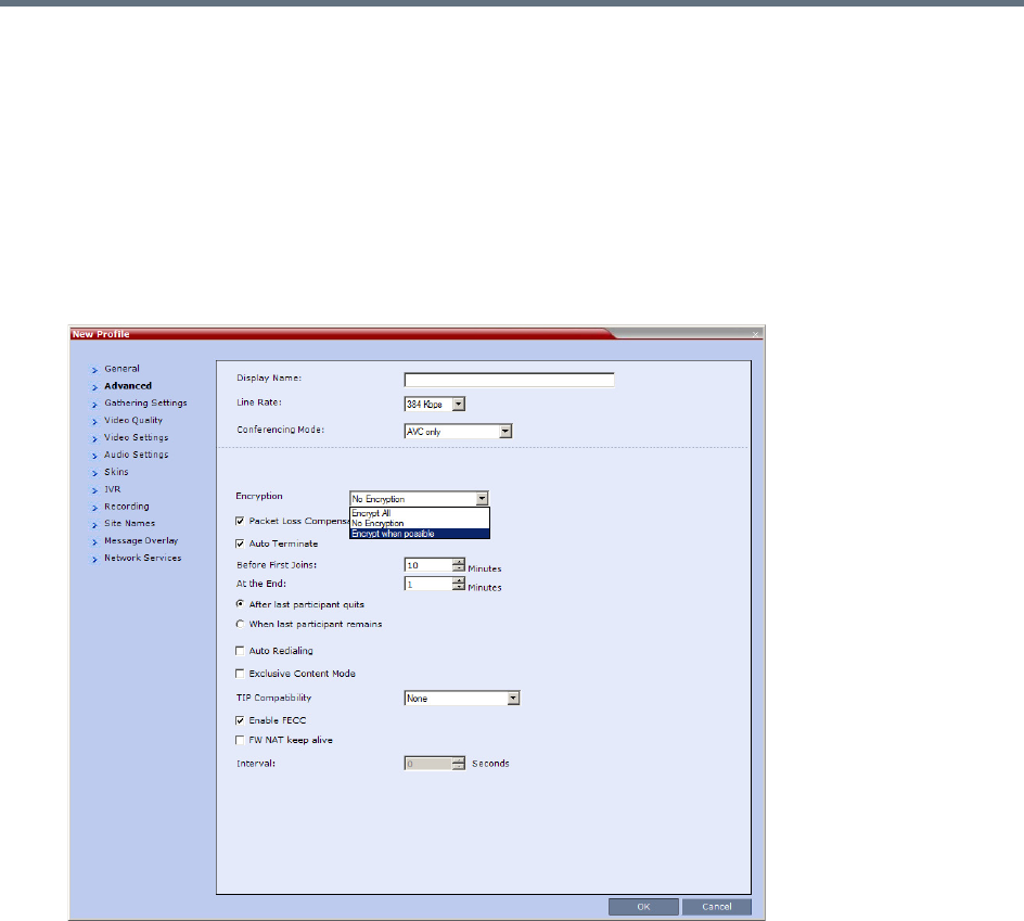
Appendix I - Polycom Open Collaboration Network (POCN)
Polycom®, Inc. 1050
Cisco endpoints running Version 1.9.1
C20, C40, C60, and C90 running TC5
CTS500
CTS1310
CTS3010
To enable DTLS negotiation for content encryption:
1In a new or existing Profile, click the Advanced tab.
2Set Encryption to either Encrypt All or Encrypt when possible.
3Set FORCE_ENCRYPTION_FOR_UNDEFINED_PARTICIPANT_IN_WHEN_AVAILABLE_MODE
System Flag to NO
These setting will enable encrypted and non-encrypted H.323 participants to connect to encrypted or
non-encrypted conferences.
For more information see Encryption.
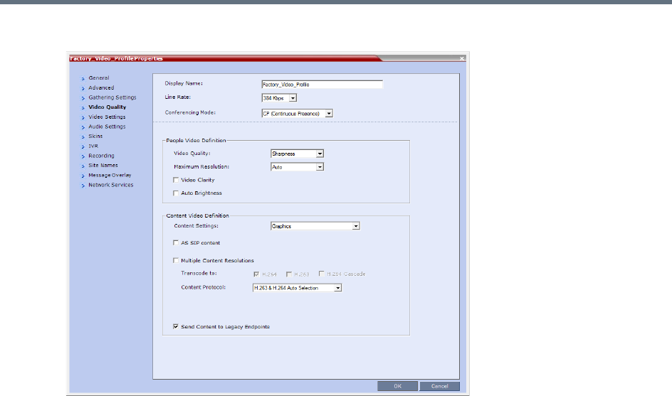
Appendix I - Polycom Open Collaboration Network (POCN)
Polycom®, Inc. 1051
aClick the Video Quality tab.
Content Settings is disabled if TIP Compatibility is set to Prefer TIP in the Advanced tab.
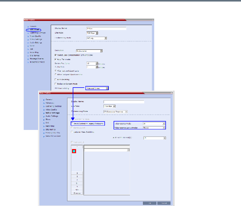
Appendix I - Polycom Open Collaboration Network (POCN)
Polycom®, Inc. 1052
bClick the Video Settings tab.
cSet the Telepresence Mode to Auto/On and select the Telepresence Layout Mode.
4Assign the New Profile to the Meeting Room. For more information see Creating a New Meeting
Room.
5Configure a Virtual Meeting Room (VMR) on the DMA.
The procedures for configuring DMA are described in detail in the Polycom Unified Communications
Deployment Guide for Cisco Environments.
Resolution Configuration
The resolution configuration dialog box is not applicable to TIP-enabled conferences as it uses fixed
settings.

Appendix I - Polycom Open Collaboration Network (POCN)
Polycom®, Inc. 1053
HD Video Resolutions for TIP calls are determined according to the following table:
Endpoints
1Configure HDX endpoints to register to Lync Server.
2Configure H.323 endpoints to register to DMA as SIP Proxy
3Configure SIP endpoints to register to:
DMA as SIP Proxy
Lync Server as SIP Proxy
CUCM as SIP Proxy
4Configure TIP endpoints to register to:
DMA
CUCM
For more information on the above, see Polycom Unified Communications Deployment Guide for Cisco
Environments.
Content
Endpoint Registration and Dialing Method affect the Video and Content Sharing characteristics of the
conference as detailed below.
TIP HD Video Resolution by Line Rate
Line Rate Video Resolution
Line Rate >=3Mbps HD1080p30
3Mbps > Line Rate >= 936kbps HD720p30
Line Rate < 936kbps Call is dropped.
Video and Content
Endpoint Registration Lync CUCM DMA
Dialing Method
ITP /HDX
RTV Key is required for
HDX and ITP
ITP /HDX
TIP Key is required for
HDX
ITP /HDX
TIP Key is required for
HDX
HDX to Collaboration
Server
•HD H.264 Video
•SIP P+C
•Content: XGA,5fps
•ICE
•HD H.264 Video
•No Content
•ICE not supported
•HD H.264 Video
•SIP P+C
•Content: XGA,5fps
•ICE not supported
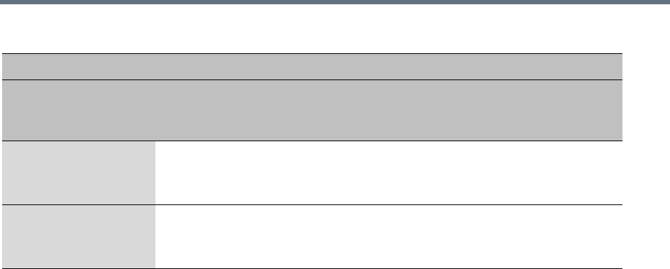
Appendix I - Polycom Open Collaboration Network (POCN)
Polycom®, Inc. 1054
Operations During Ongoing Conferences
Moving participants between TIP enabled meetings and non TIP enabled meetings is not possible.
Monitoring
CTS Participants
1In the Participant List pane double-click the participant entry. Alternatively, right-click a participant
and select Participant Properties.
The Participant Properties - General dialog box opens.
2Click the SDP tab.
The following are indicated in the Remote Capabilities, Remote Communication Mode and Local
Communication Mode panes:
AAC_LD - Audio Protocol
Lync to Collaboration
Server
•HD Video (RTV)
•No Content Sharing
•Content sent to Lync using Content for Legacy Endpoints
CTS to Collaboration
Server
•HD1080p30
•TIP Content Sharing
•Content: XGA,5fps
Video and Content
Endpoint Registration Lync CUCM DMA
Dialing Method
ITP /HDX
RTV Key is required for
HDX and ITP
ITP /HDX
TIP Key is required for
HDX
ITP /HDX
TIP Key is required for
HDX
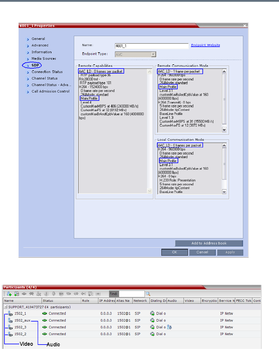
Appendix I - Polycom Open Collaboration Network (POCN)
Polycom®, Inc. 1055
●Main Profile - Video protocol
When viewing CTS systems in the Participants list, the individual video screens and the Audio Channel
(AUX) of the CTS system are listed as separate participants. The Participant list below shows a connected
CTS 3000, a 3-screen system.
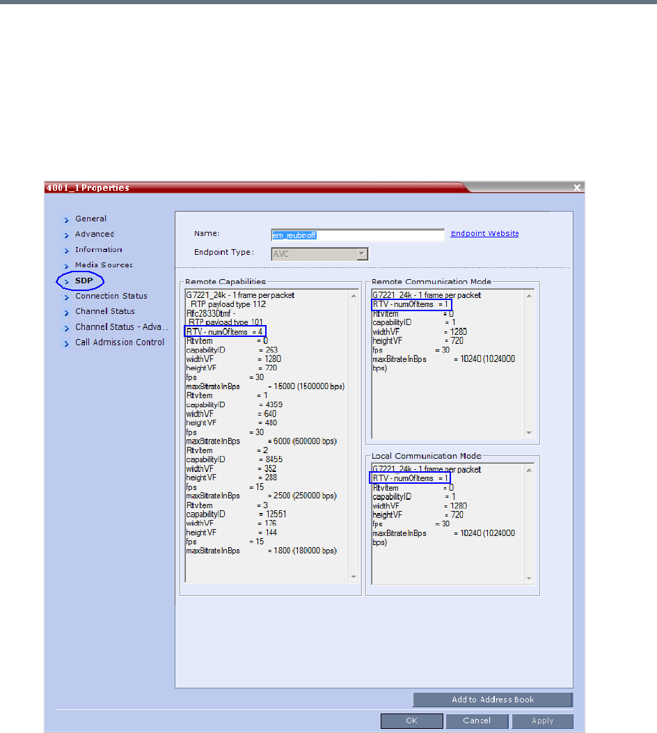
Appendix I - Polycom Open Collaboration Network (POCN)
Polycom®, Inc. 1056
Lync Participants (RTV)
1In the Participant List pane double-click the participant entry. Alternatively, right-click a participant
and select Participant Properties.
The Participant Properties - General dialog box opens.
2Click the SDP tab.
RTV is indicated in the Remote Capabilities, Remote Communication Mode and Local
Communication Mode panes:
3Click the Channel Status - Advanced tab
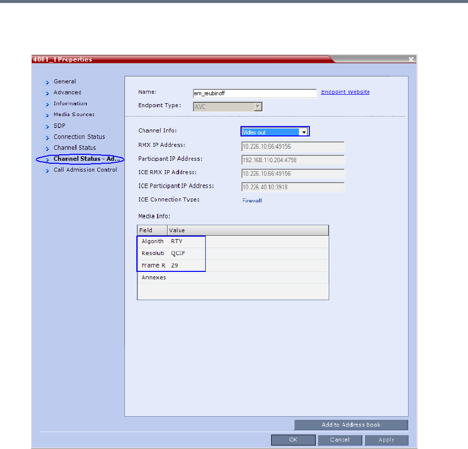
Appendix I - Polycom Open Collaboration Network (POCN)
Polycom®, Inc. 1057
4In the Channel Info drop-down menu select Video Out.
Media Info displays RTV Channel Status parameters:
Known Limitations
The following may occur in the collaborative environment:
●Artifacts and ghosting may appear when Lync Clients and CTS endpoints connect to the VMR.
Frequency: Seldom.
●Lync Client receives fast updates (Intra) from CTS 500 endpoints causing the screen to refresh
repeatedly.
Frequency: Often.
●Audio volume and video quality decreases on CTS endpoints.
Frequency: Seldom.

Appendix I - Polycom Open Collaboration Network (POCN)
Polycom®, Inc. 1058
●CTS endpoint connects and then disconnects after a few seconds.
Frequency: Seldom.
●Lync Clients always connect encrypted to non-encrypted conferences.
●Auto Layout sometimes ignored for CTS and Lync Clients calling through DMA.
Frequency: Rarely.
●Content sent from HDX endpoint is received by all endpoints for 1 second before stopping.
Conference is Content to Legacy enabled and TIP Compatibility is Prefer TIP.
Frequency: Often.

Polycom®, Inc. 1059
Appendix J - Restore Defaults
Administrators can erase the current Collaboration Server configurations and restore default system
settings. Two options are available:
●Standard Restore
Delete customer conferencing entities and keep only system default conferencing entities. However,
the management network service and license info are not deleted.
●Comprehensive Restore
Restore the MCU to the settings it had when shipped from the factory. The Default Management
Network and license information are deleted and the system hard disk file partition is formatted.
Perform a Standard Restore
A standard restore deletes the following files:
●CDR
●Address Book
●Log Files
●Faults
●Dump Files
●Notes
In addition, all the conferencing entities are deleted:
●Entry Queues
●Profiles
●Meeting Rooms
●IVR Services
●Default Network IP Service
When the system is restarted, these conferencing entities are created based on the system defaults. In
addition, the Fast Configuration Wizard runs automatically, enabling the user to configure the Default IP
Network Service.
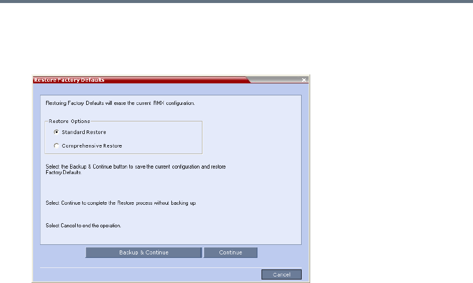
Appendix J - Restore Defaults
Polycom®, Inc. 1060
To perform a Standard Restore using the RMX Web Client:
1In the RMX Web Client, click Administration > Tools > Restore Factory Defaults.
2In the Restore Factory Defaults dialog, select Standard Restore.
3Click one of the following buttons:
Backup & Continue—Backup of the current Collaboration Server configuration. Select this
option if you wish to restore the current conferencing entities and system configuration after the
Standard Restore.
Proceed with step 4.
Continue—Initializes all the current system configuration files and conferencing entities and then
restores them to their system default values according to the selected restore level.
Proceed with step 5.
Cancel—cancels and exits this dialog box.
4In the Backup Configuration Dialog dialog, click Browse to select the Backup Directory Path
and select Backup.
The system initiates the backup of the Collaboration Server configuration files. When the backup
completes, a confirmation dialog box is displayed. To cancel the backup, click Close.
5Click Yes to restore the Collaboration Server.
6When prompted to reset the system now, click Yes.
7Following the system restart, follow the instructions in the RealPresence Collaboration Server
(RMX) 1500/1800/2000/4000 Getting Started Guide:
Modify Network Settings in USB Key
First Time Power Up

Appendix J - Restore Defaults
Polycom®, Inc. 1061
Perform a Comprehensive Restore
Restore the MCU to the default settings of the current software version.
In addition to files deleted when you Perform a Standard Restore, the following files are also deleted:
●CFS license information
●Management Network Service
You can perform a comprehensive restore in one of the following ways:
●Using the RMX Web Client (Recommended).
●Using the USB key.
Use the USB key for system restore only when you cannot do it from the system Web Client. For
example, when the Web Client isn’t accessible.
Note: Product Activation Key is required after a Comprehensive Restore
After a Comprehensive Restore, the Product Activation Key is required to reconfigure the
Management Network Service during the First Entry Configuration.
Warning: Insert a USB device into the Collaboration Server’s USB port ONLY when you want to
perform a system restore
Inserting a USB key containing the following files causes the Collaboration Server to exit Secure
Mode and perform a Comprehensive Restore:
•Collaboration Server (RMX) 1500/2000/4000—RestoreToFactoryDefault.txt and lan.cfg
•Collaboration Server (RMX) 1800—USB_action.cfg and lan.cfg
Do not insert a USB device into the Collaboration Server’s USB port unless it is your intention
to disable Secured Mode or perform a Comprehensive Restore to system defaults.
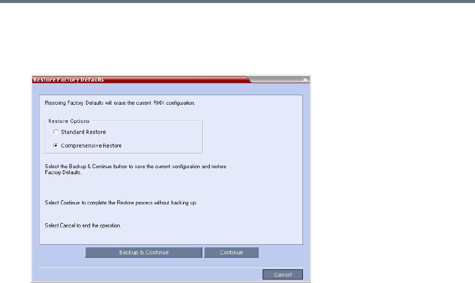
Appendix J - Restore Defaults
Polycom®, Inc. 1062
To perform a comprehensive restore using the RMX Web Client:
1In the RMX Web Client, click Administration > Tools > Restore Factory Defaults.
2In the Restore Factory Defaults dialog, select Comprehensive Restore.
3Click one of the following buttons:
Backup & Continue—Backup of the current Collaboration Server configuration. Select this
option if you wish to restore the current conferencing entities and system configuration after the
Standard Restore.
Proceed with step 4.
Continue—Initializes all the current system configuration files and conferencing entities and then
restores them to their system default values according to the selected restore level.
Proceed with step 5.
Cancel—cancels and exits this dialog box.
4In the Backup Configuration Dialog dialog, click Browse to select the Backup Directory Path
and select Backup.
The system initiates the backup of the Collaboration Server configuration files. When the backup
completes, a confirmation dialog box is displayed. To cancel the backup, click Close.
5Click Yes to restore the Collaboration Server.
6When prompted to reset the system now, click Yes.
7Following the system restart, follow the instructions in the RealPresence Collaboration Server
(RMX) 1500/1800/2000/4000 Getting Started Guide:
Modify Network Settings in USB Key
First Time Power Up
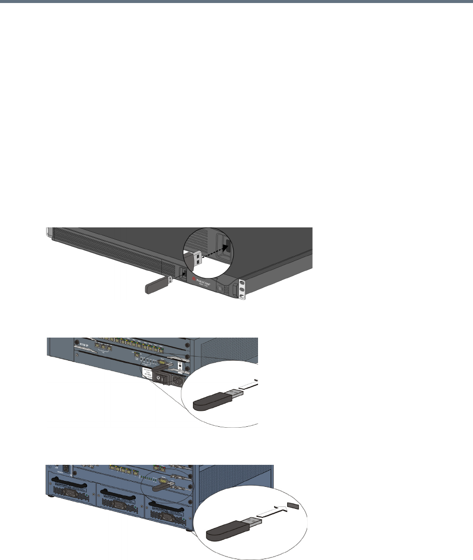
Appendix J - Restore Defaults
Polycom®, Inc. 1063
To perform a Comprehensive Restore using the USB key (1500/2000/4000):
1 Optional. Back up the system configuration:
aIn the RMX Web Client, click Administration > Software Management > Backup
Configuration.
bClick Browse to select a backup directory.
cClick Backup.
Perform this step if you wish to restore the current conferencing entities and system configuration
after the Comprehensive Restore.
2Insert the USB key that was included with your system into the workstation.
By default, the USB key contains files ToFactoryDefault.txt and a lan.cfg file which are used to trigger
the restore. However, if they are missing, you can create two blank .txt files with these names. (The
content of these two files doesn’t matter.)
The USB port locations for Collaboration Servers (RMX) 1500/2000/4000 are shown below:
RealPresence Collaboration Server (RMX) 1500—left most USB port on the front panel.
RealPresence Collaboration Server (RMX) 2000—at the bottom right corner of the RTM IP card
on the back panel.
.
RealPresence Collaboration Server (RMX) 4000—at the bottom right corner of the RTM IP 4000
card on the back panel.
3Power off and then power on the Collaboration Server.
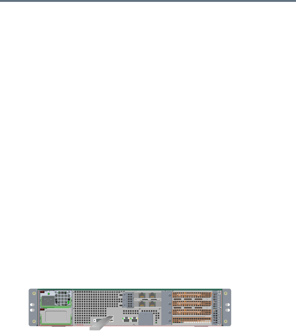
Appendix J - Restore Defaults
Polycom®, Inc. 1064
4Following the system restart, follow the instructions in the RealPresence Collaboration Server
(RMX) 1500/1800/2000/4000 Getting Started Guide:
Modify Network Settings in USB Key
First Time Power Up
To perform a comprehensive restore using the USB key (1800):
1Insert the USB key that is included with the system into your workstation:
In Windows XP:
The Polycom Documentation option is automatically selected. Click OK.
In Windows 7:
Select Open Folder to view files using Windows Explorer.
2Double-click the index.hta file.
3In the Language Menu window, click the hyperlink for the required documentation language.
4In the Polycom End User Licenses Agreement window, read the agreement and click the Accept
Agreement button.
In the Product Type Selection window, click RealPresence Collaboration Server 1800.
5Under the Support Utilities, select Restore to Factory Defaults.
6 Optional. In Restore to Factory Defaults window, select LAN Configuration and configure the
following:
Control Unit IP Address
Subnet Mask:
Default Router IP Address
This will configure the system to the local network so the administrator can access the RMX Web
Client from the local workstation when the system restarts.
If you skip this step, you can configure these settings later using the LAN Configuration Utility
included on the USB key.
7Remove the USB key from the workstation.
Insert the USB key into either of the two USB ports on the back panel of the Collaboration Server
(RMX)1800 system.
8Power off and then power on the Collaboration Server1800 system.
9Following the system restart, follow the instructions in the RealPresence Collaboration Server
(RMX) 1500/1800/2000/4000 Getting Started Guide:
Modify Network Settings in USB Key
First Time Power Up

Polycom®, Inc. 1065
Appendix K - SIP RFC Support
SIP RFC Support in RealPresence Collaboration Server (RMX) Systems
SIP RFC Description Note
1321 MD5
2032 RTP Payload for H.261
2205 RSVP
2327 Session Description Protocol (SDP)
2429 RTP Payload for H.263+
2833 RTP Payload for DTMF
2617 HTTP Authentication
2976 SIP Info Method
3261 SIP
3264 Offer/Answer Model
3265 SIP Specific Event Notification Limited support
3266 SDP Support for IPv6
3311 SIP Update Method
3515 SIP Refer Method Limited support
3550 RTP
3551 RTP Profile for Audio/Video
3711 SRTP
3890 Transport Independent Bandwidth Modifier for SDP
3891 SIP Replaces header Limited support
3892 SIP Referred-by Mechanism Limited support
3984 RTP Payload format for H.264
4028 Session Timers in SIP
4145 TCP Media Transport in SDP
4566 Session Description Protocol (SDP)
4568 SDP Security Descriptions
4573 H.224 RTP Payload (FECC)
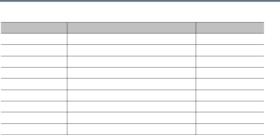
Appendix K - SIP RFC Support
Polycom®, Inc. 1066
4574 SDP Label Attribute
4582 Binary Floor Control Protocol (BFCP)
4583 SDP for BFCP
4796 SDP Content Attribute
5168 XML Schema for Media Control (Fast Update)
cc-transfer Call Transfer Capabilities in SIP Limited support
draft-ice-19 ICE spec for firewall traversal in SIP
draft-turn-07 TURN spec for firewall traversal in SIP
draft-rfc3489bis-15 STUN spec for firewall traversal in SIP
SIP RFC Support in RealPresence Collaboration Server (RMX) Systems
SIP RFC Description Note

Polycom, Inc. 1067
Appendix L - Media Traffic Shaping
Polycom integrated traffic shaping capabilities into the RealPresene Collaboration Server to enable
deploying Collaboration Server systems in networks limiting packet bursts within 100ms time intervals (or
more). Setting router policies to limiting of bandwidth within a time interval, causes the router to drop packets
exceeding the allowed bandwidth within this interval. Therefore, using this feature enables the MCU to
flatten the traffic, and minimize traffic bursts, without exceeding the bandwidth allowed within the time
interval.
Though the Collaboration Server supports high level network features, high quality of service requires
end-to-end video network operation. The Collaboration Server traffic shaping capabilities cannot compensate
for network level violations/limitations generated by elements outside the MCU, such as endpoints, routers,
etc.
Traffic shaping can flatten a momentary burst (meaning, within a 100ms time interval). However, it cannot
“flatten” longer bursts resulting from endpoints sharing content in video switching conferences. Similarly, this
feature helps reducing packets dropping by routers following momentary traffic bursts, yet it does not
resolve packet lost by faulty network connections or network congestion.
Note that during VSW content sessions, should source endpoint exceed the negotiated content rate for over
100ms, the Collaboration Server can flatten the video channel but not the incoming content channel.
Traffic Shaping Guidelines
●Traffic shaping is applied in the following conferencing modes and scenarios:
AVC conferences (both CP and VSW)
Mixed CP and SVC conferences - applied only on AVC endpoints
Content VSW
This feature is not applied on TIP endpoints.
●Capacity of CIF/SD resolutions on MPMx cards is reduced when traffic shaping is on: CIF capacity is
reduced from 90 to 70 (20% reduction), and SD capacity is reduced from 60 to 50, in terms of ports.
Capacity of mixed AVC/SVC calls is also reduced when traffic shaping is enabled.
Capacities of 720p and up are unaffected.
●License entitlement ratio for SD and CIF is reduced from 1:2 to 1:1.5 on Collaboration Servers with
MPMRx media card(s); license entitlement ratio for SD is reduced from 1:2 to 5:3, and for CIF - from
1:2 to 7:3 on Collaboration Servers with MPMx media card(s).
●Traffic shaping code is embedded in the DSP ART modules thus requiring enlarging PCI memory size
to 18Mbps, and content memory size to that of video.
●In MPMx MCUs, if all DSP units are defined as ART, each MPMx-D card can allocate 360 audio-only
ports. Yet, if all DSP units are set to full video (meaning, no voice), a CIF port is allocated for audio
only, resulting in audio capacity reduction similar to that of CIF capacity reduction (see Capacity
Reduction in MPMx and MPMRx MCUs).
●Should license port capacity be lower than the number of hardware ports, the unlicensed ports are
used for traffic shaping to decrease capacity reduction.
●Traffic shaping is applied on the aggregation of both content and people channels.

Appendix L - Media Traffic Shaping
Polycom, Inc. 1068
●Delays due to traffic shaping, if any, are limited to 10ms.
●This feature is not applied on audio, since the encoder output audio rate is constant.
●When LPR is enabled, traffic shaping is applied following packets repair and prior to packets sending.
System Flags
Traffic shaping usage is controlled by Collaboration Server configuration system flags (for the entire bridge):
●ENABLE_RTP_TRAFFIC_SHAPING - Controls traffic shaping. When set to YES, traffic shaping is
applied to all ports, resulting in some port capacity reduction in MCUs with MPMx/MPMRx cards (see
Capacity Reduction in MPMx and MPMRx MCUs). When set to NO (default), traffic shaping is
disabled.
●VIDEO_BIT_RATE_REDUCTION_PERCENT - Indicates the percentage of actual reduction in bit
rate sent from the MCU to the endpoint (negotiated bit rate is not reduced). This flag is applicable
only when traffic shaping is enabled (ENABLE_RTP_TRAFFIC_SHAPING set to YES).
Range: 0-60; Default value: 15
●TRAFFIC_SHAPING_MTU_FACTOR - Used for the MTU (Maximum transmitting Unit - the size of
transmitted packets) dynamic calculation:
New MTU = video bit rate / TRAFFIC_SHAPING_MTU_FACTOR
where the new MTU value is guaranteed to be a minimum of 410, and a maximum of 1460
(MAX_MTU). The purpose of this calculation is to match video rate in outgoing video to call rate, yet
force lower encoder bit rates to avoid overflow.
This flag is applicable only when traffic shaping is enabled.
Range: 0-5000, where 0 signifies no change in MTU; Default value: 800
To modify any of these flags, manually add them into the MCMS user parameters section of the system
configuration flags, and then modify their value (see Manually Adding and Deleting System Flags).
Capacity Reduction During Traffic Shaping
The table below describes the maximum capacity left after reduction due to traffic shaping in Collaboration
Servers 1500/2000/4000. There is no capacity reduction in Collaboration Server 1800.
Capacity Reduction in MPMx and MPMRx MCUs
Resolution
MPMx MPMRx
Non-mixed Mode Mixed Mode Non-mixed Mode Mixed Mode
CIF 70 40 150 * 100 *
SD 50 40 150 * 100 *
HD720p 30 20 100 66
HD1080p 15 10 50 40
Audio Only 70/360 40/360 300 150
* Assuming conference bit rate ≤ 1024 Kbps

Polycom®, Inc. 1069
Appendix M - Homologation for Brazil
H.323 & SIP Protocol Flag Options
Using a set of system flags, the user has the ability to select either Polycom proprietary or H.323/SIP
standard protocol settings.
H.323 & SIP Flag Settings
Three flags are enabled on the Collaboration Server, allowing the user to define and select either standard
or proprietary H.323 and SIP protocol settings.
Flag name: SIP_TIMERS_SET_INDEX
Description: SIP Timer type timeout settings according to standard or proprietary protocol.
Flag section: CS_MODULE_PARAMETERS
Possible Values: either 0 or 1.
0 - Polycom standard (flag default setting)
1 - SIP Standard recommendation. For homologation and certification testing, this flag must be set to 1.
For use as a reference, the following table lists the SIP timer types for each flag setting and their
corresponding timeout values in milliseconds.
SIP Timer Types
SIP TIMER Types Value (in milliseconds)
POLYCOM (flag default) Standard Recommended
T1 50000 500
T2 20000 4000
TimerB 35000 32000
TimerC 35000 60000
TimerD 32000 32000
TimerF 35000 32000
TimerH 35000 32000
TimerI 5000 5000
TimerJ 32000 32000
TimerK 5000 5000

Appendix M - Homologation for Brazil
Polycom®, Inc. 1070
Flag name: H323_TIMERS_SET_INDEX
Flag description: Enables or disables H.323 index timer according to standard or proprietary H.323 protocol.
Section CS_MODULE_PARAMETERS
Possible values:
0 - Sets the H.323 index timer to Polycom proprietary (flag default setting)
1 - Sets the H.323 index timer based on the H.323 Standard recommendation. For homologation and
certification testing, this flag must be set to 1.
Flag name: DISABLE_DUMMY_REGISTRATION
Flag description: Enables or disables SIP dummy registration on the domain.
Flag Section: MCMS_PARAMETERS_USER
Possible values:
NO - Disables SIP dummy registration (flag default setting).
YES - Enables SIP dummy registration. For homologation and certification testing, the flag must be set to
YES.
