Pontiac Automobile Parts Users Manual 250 4166
Automobile Parts to the manual af38e34c-c8fe-43ed-8272-1941eef59ef7
2015-01-23
: Pontiac Pontiac-Automobile-Parts-Users-Manual-272652 pontiac-automobile-parts-users-manual-272652 pontiac pdf
Open the PDF directly: View PDF ![]() .
.
Page Count: 5
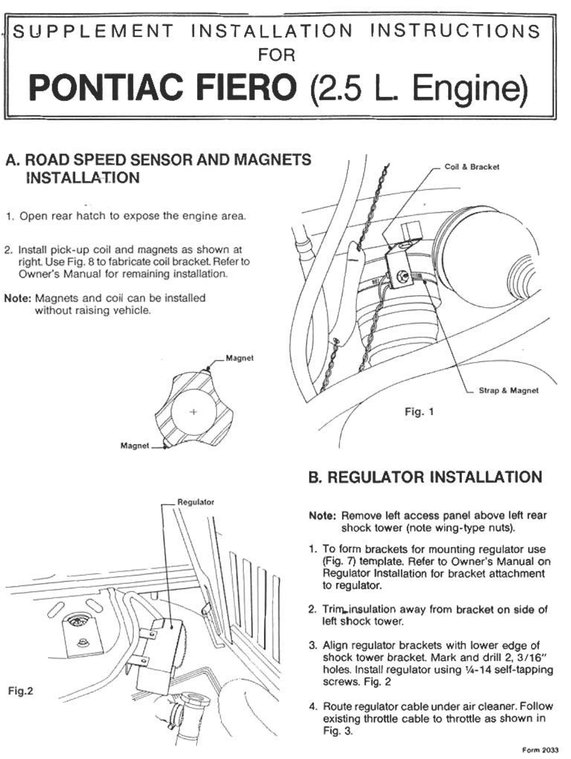
B. REGULATOR INSTALLATION
Note: Remove left access panel above left rear
shock tower (note wing-type nuts).
1. To form brackets for mounting regulator use
(Fig. 7) template. Refer to Owner's Manual on
Regulator Installation for bracket attachment
to regulator.
2. Trirn..il1sulation away from bracket on side of
left shock tower.
3. Align regulator brackets with lower edge of
shock tower bracket. Mark and drill 2, 3/16"
holes. Install regulator using 1/4-14 self-tapping
screws. Fig. 2
4. Route regulator cable under air cleaner. Follow
existing throttle cable to throttle as shown in
Fig. 3.
Form 2033
.rap
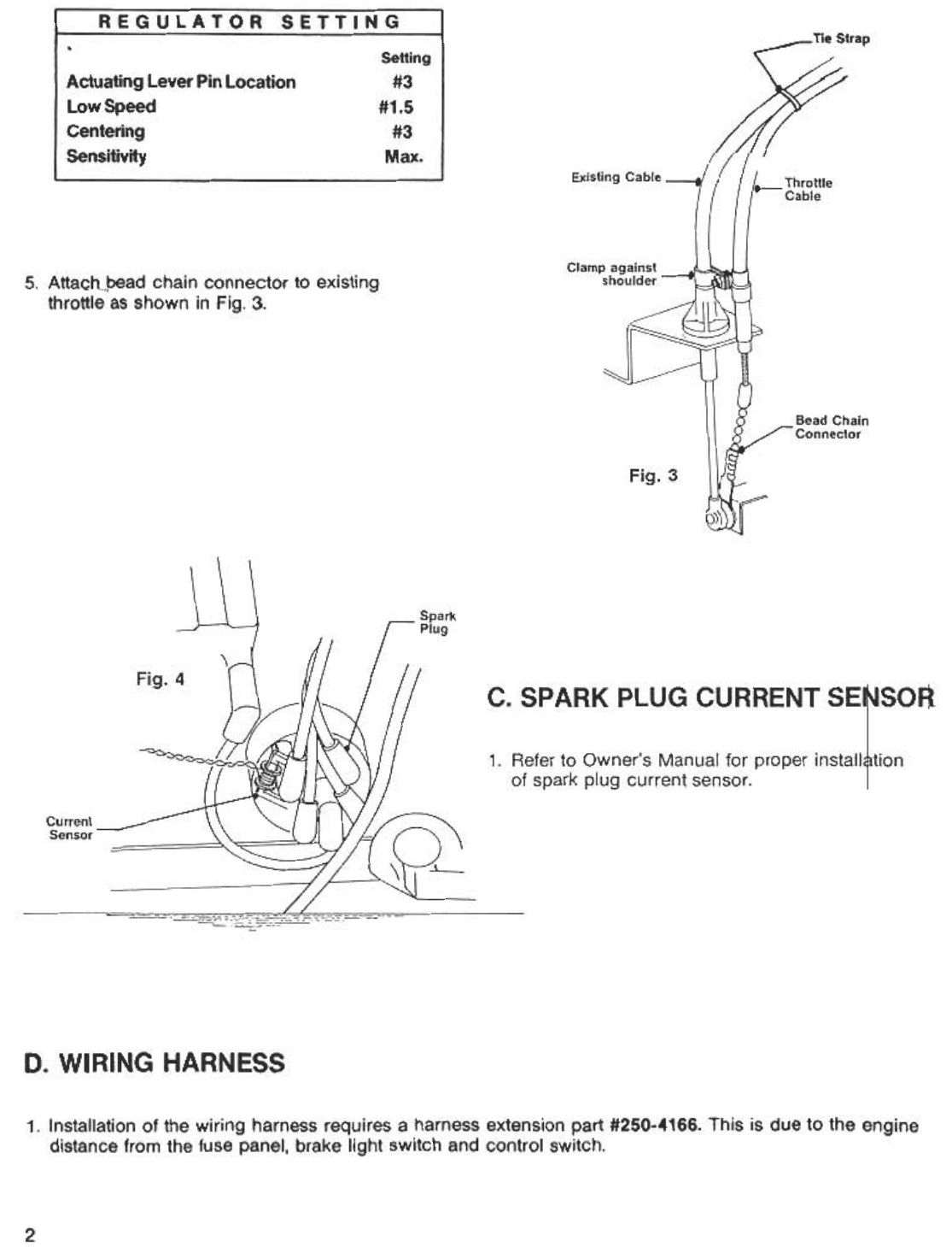
5. Attach~bead chain connector to existing
throttle as shown in Fig. 3.
D. WIRING HARNESS
1. Installation of the wiring harness requires a harness extension part #250-4166. This is due to the engine
distance from the fuse panel, brake light switch and control switch.
2
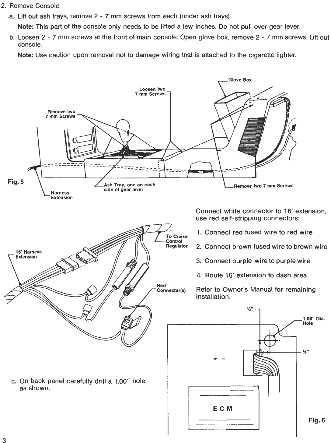
2. Remove Console
.a. Lift out ash trays. remove 2 -7 mm screws from each (under ash trays).
Note: This part of the console only needs to be lifted a few inches. Do not pullover gear lever.
b. Loosen 2 -7 mm screws at the front of main console. Open glove box, remove 2 -7 mm screws. Lift out
console.
Note: Use caution upon removal not to damage wiring that is attached to the cigarette lighter.
Glove Box
Loosen two
7 mm Screws ./
?~
Removetwo
7 mm .Screws ~
.,
~
~--"-~--~-:~:
Fig. 5 Ash Tray, one on each
side of gear lever Remove two 7 mm Screws
Harness
Extension
Connect white connector to 16' extension,
use red self-stripping connectors:
3
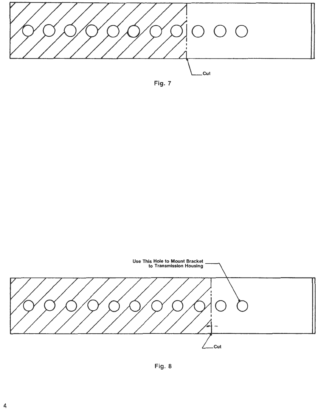
Fig.7
Fig.8
4
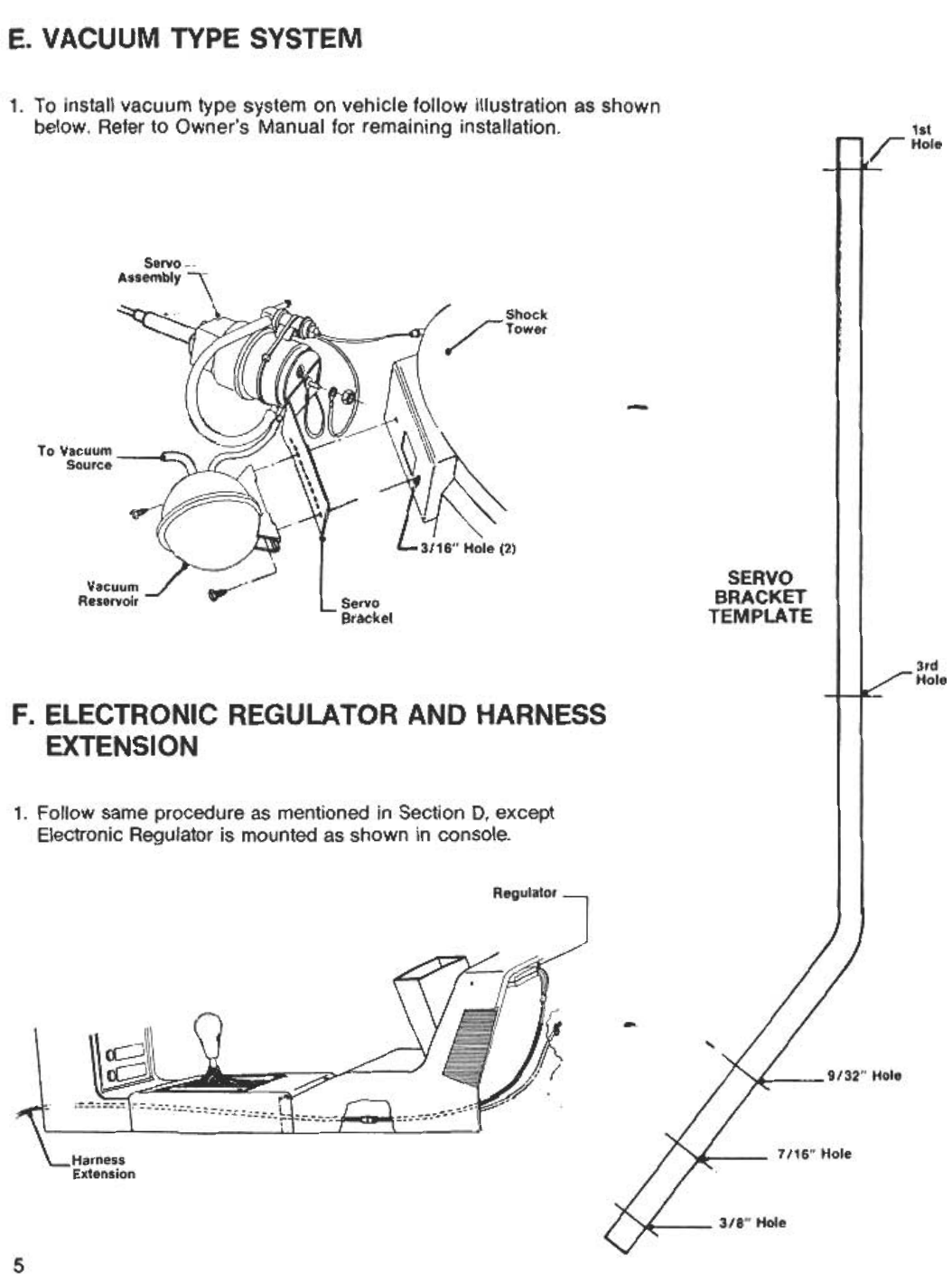
E. VACUUM TYPE SYSTEM
1. To install vacuum type system on vehicle follow illustration as shown
below. Refer to Owner's Manual for remaining installation.
Servo-
Assembly
~.
/ Shock
/TOWer
-
'\ \-.-
'-
To Vacuum ---c: Source ,~
/---11
~
~
R~:~~~~ ~ SERVO
BRACKET
TEMPLATE
Servo
Bracket
3rd
Hole
F. ELECTRONIC REGULATOR AND HARNESS
EXTENSION
1. Follow same procedure as mentioned in Section D, except
Electronic Regulator is mounted as shown in console.
Regulator
,
rC- l!f
~ 'I>
o y'(
-"
9132.. Hole
~
:'-'r
Harness
Extension 7/16"Hole
318" Hole
5
1st
-/HOle
~
3116" Hole (2)
