Portwell WISP5 Wireless Service Platform User Manual WISP
Portwell, Inc. Wireless Service Platform WISP
UserManual.wiki
>
Portwell
>
WISP5 User Manual
User manual
Navigation menu
Upload a User Manual
Namespaces
Wiki Guide
HTML
PDF
Info
Views
User Manual
Discussion / Help
Navigation


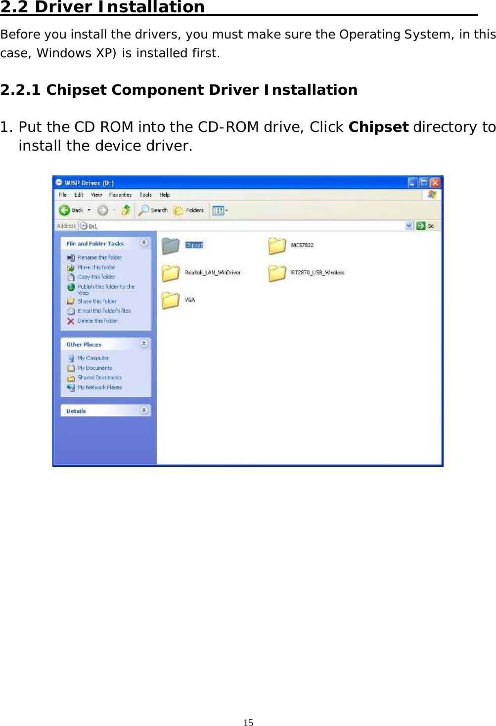
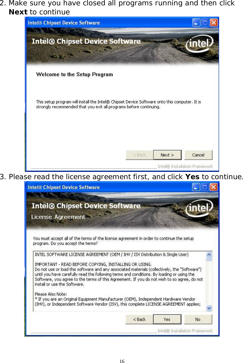
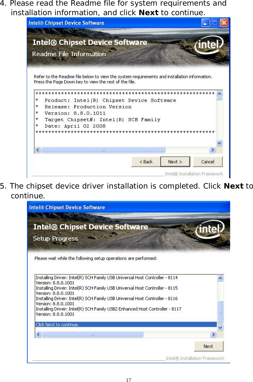
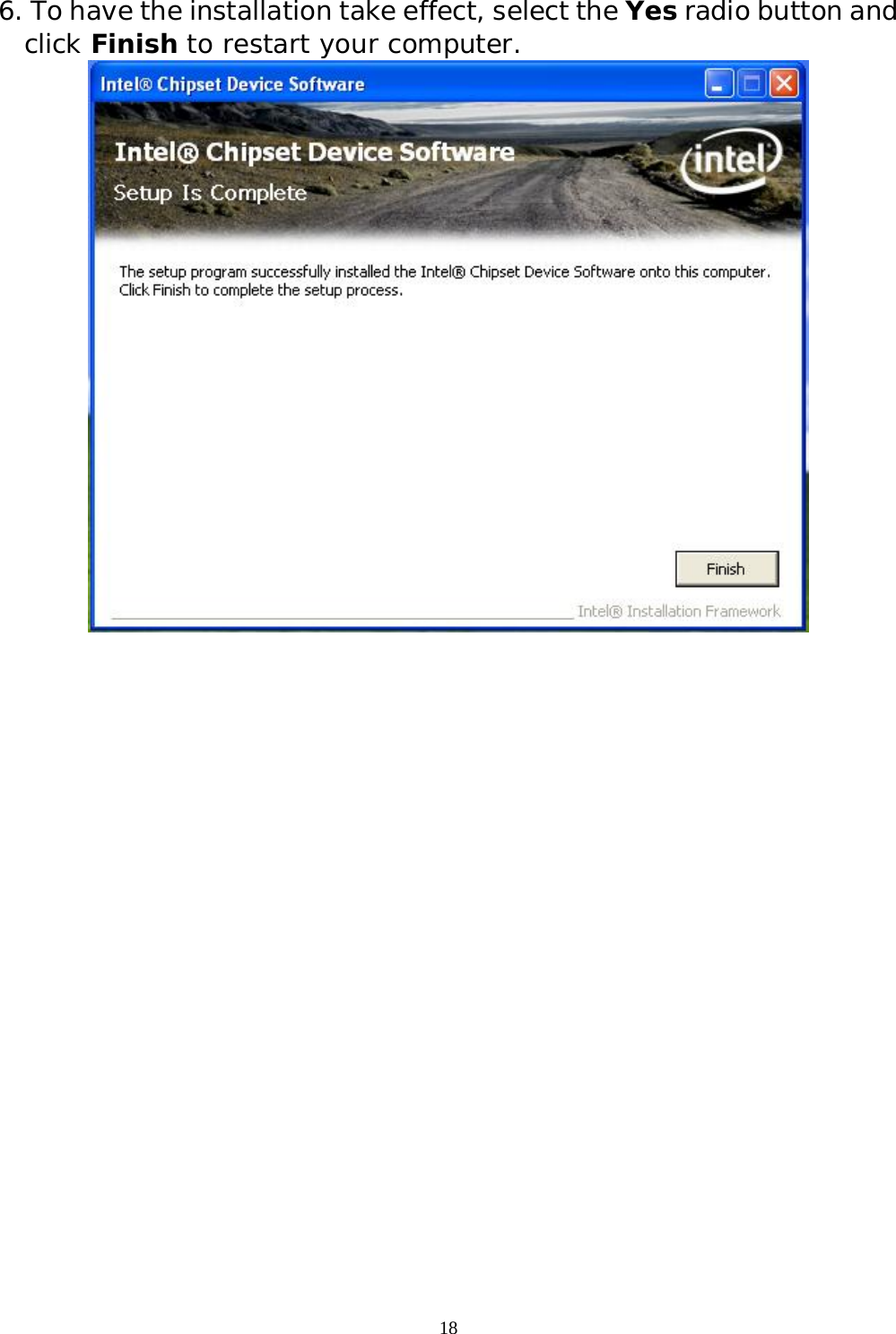

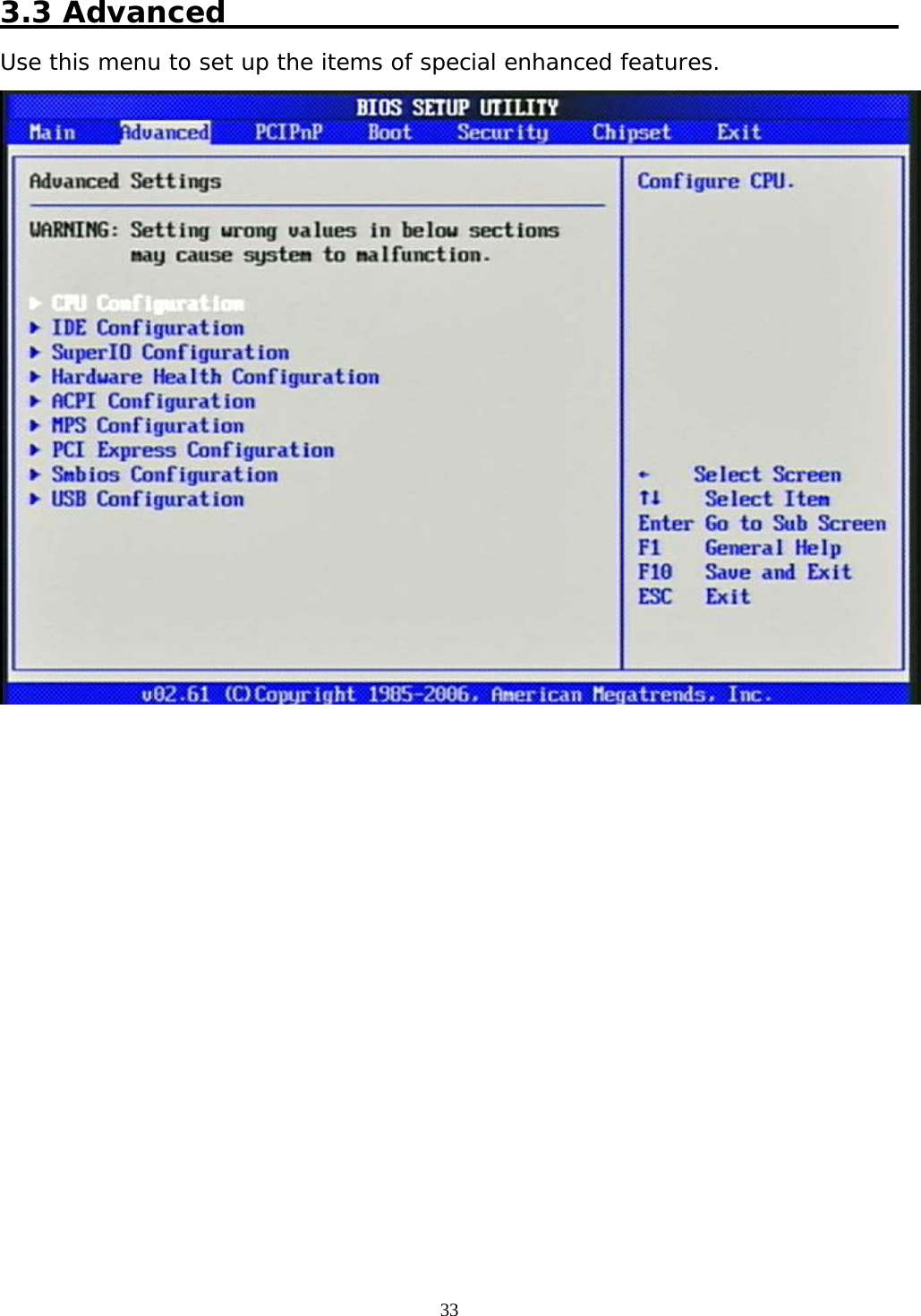
![32 3.2 Main Menu Use this menu for basic system configurations such as time, date etc. AMI BIOS, Processor, System Memory These items show the firmware and hardware specifications of your system. Read only. System Time The time format is <Hour> <Minute> <Second>. Use [+] or [-] to configure system Time. System Date The date format is <Day>, <Month> <Date> <Year>. Use [+] or [-] to configure system Date.](https://usermanual.wiki/Portwell/WISP5/User-Guide-3627642-Page-32.png)
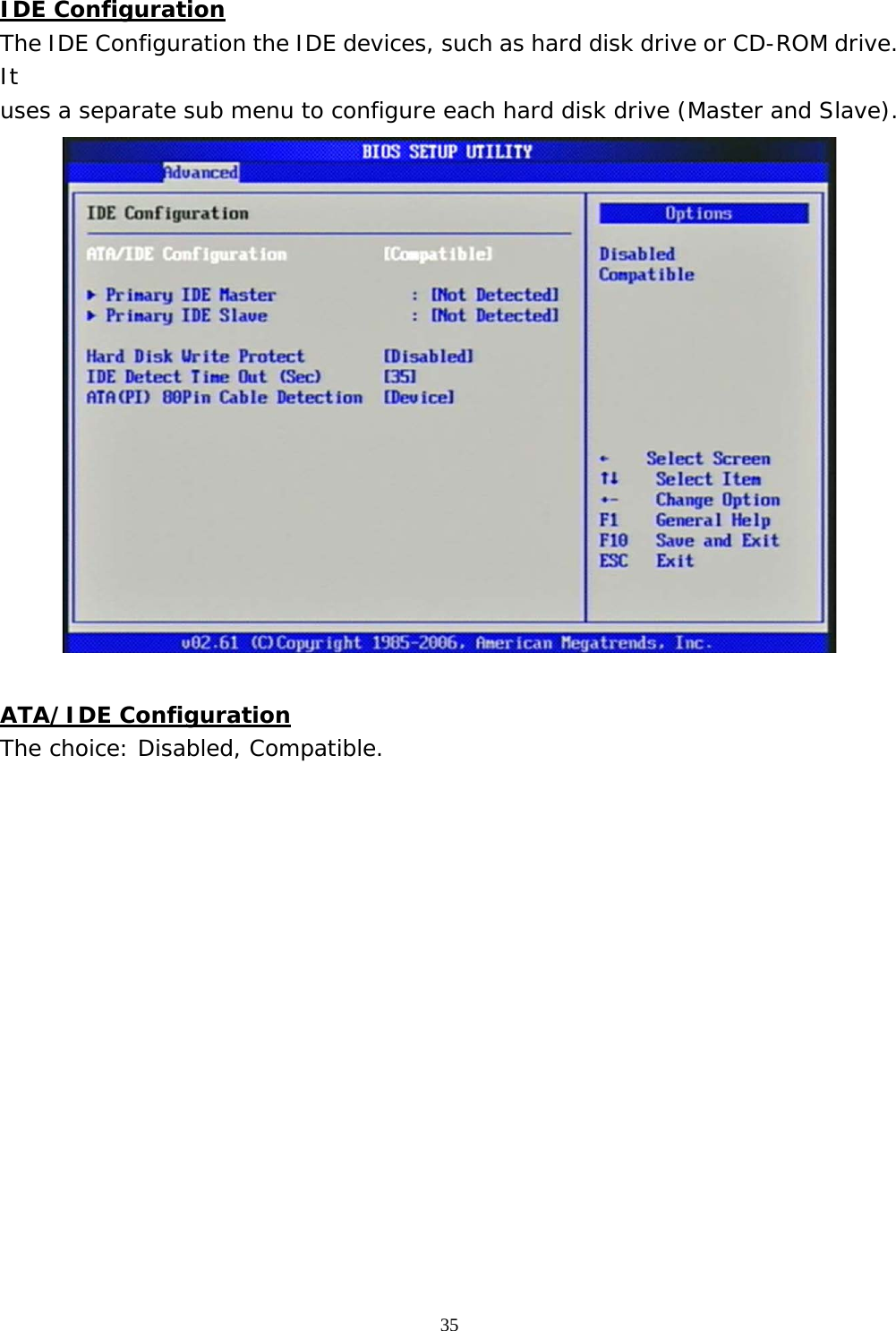
![36 Primary IDE Master/Slave While entering setup, BIOS auto detects the presence of IDE devices. This display shows the status of auto detection of IDE devices. [Type] Press PgUp/<+> or PgDn/<-> to select [Manual], [None] or [Auto] type. You can use [Manual] to define your own drive type manually. [LBA/Large Mode] Enabling LBA causes Logical Block Addressing to be used in place of Cylinders, Heads and Sectors. [Block (Multi-Sector Transfer)] Any selection except Disabled determines the number of sectors transferred per block. [PIO Mode] Indicates the type of PIO (Programmed Input/Output). [DMA Mode] Indicates the type of Ultra DMA.](https://usermanual.wiki/Portwell/WISP5/User-Guide-3627642-Page-36.png)
![37 [S.M.A.R.T.] This allows you to activate the S.M.A.R.T. (Self-Monitoring Analysis & Reporting Technology) capability for the hard disks. S.M.A.R.T is a utility that monitors your disk status to predict hard disk failure. This gives you an opportunity to move data from a hard disk that is going to fail to a safe place before the hard disk becomes offline. [32 Bit Data Transfer] Enable/Disable 32-bit Data Transfer. Hard Disk Write Protect Disabled/Enabled device write protection, this will be effective only if device is accessed through BIOS. The choice: Disabled, Enabled. IDE Detect Time Out (Sec) Select the time out value for detecting ATA/ATAPI device (s). The choice: 0, 5, 10, 15, 20, 25, 30, 35. ATA (PI) 80Pin Cable Detection Select the mechanism for detecting 80Pin ATA (PI) cable. The choice: Host & Device, Host, Device. Super IO Configuration Serial Port 1 Address Allows BIOS Select Serial Port1 Base Addresses. The choice: Disabled, 3F8/IRQ4. Watch Dog Timer Set This BIOS testing option is able to reset the system according to the selected table.](https://usermanual.wiki/Portwell/WISP5/User-Guide-3627642-Page-37.png)
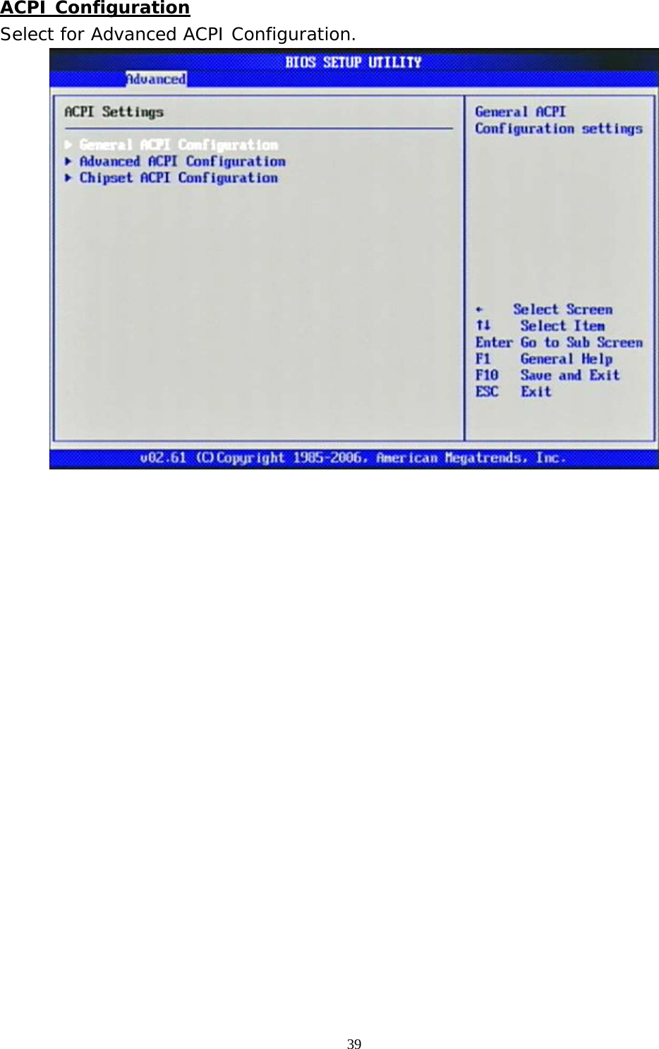
![40 General ACPI Configuration Suspend mode This item specifies the power saving modes for ACPI function. If your operating system supports ACPI, you can choose to enter the Standby mode in S3 (STR) function through the setting of this field. Option is: [S3 (STR)] The S3 sleep mode is a lower power state where the information of system configuration and open applications/ files is saved to main memory that remains powered while most other hardware components turn off to save energy. The information stored in memory will be used to restore the system when a “wake up” event occurs. Repost Video on S3 Resume Determines whether to invoke VGA BIOS post on S3/STR resume. The choice: No, Yes](https://usermanual.wiki/Portwell/WISP5/User-Guide-3627642-Page-40.png)
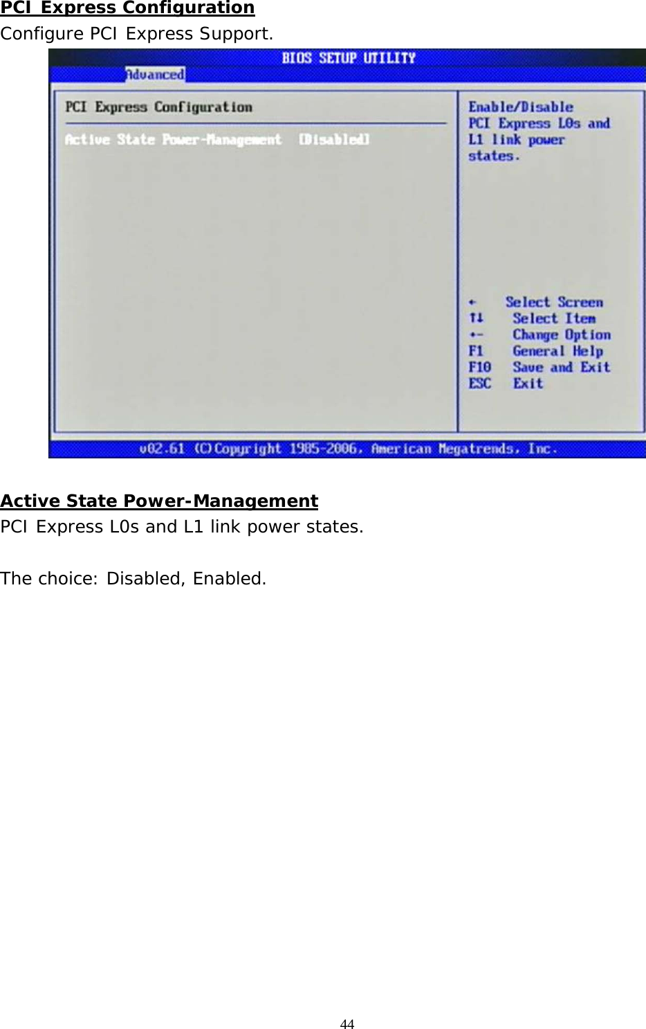
![46 USB Configuration Legacy USB Support Set to [Enabled] if you need to use any USB 1.1/2.0 device in the operating system that does not support or have any USB 1.1/2.0 driver installed, such as DOS and SCO Unix. The choice: Disabled, Enabled, Auto. USB 2.0 Controller Mode This setting specifies the operation mode of the onboard USB 2.0 controller. The choice: FullSpeed, HiSpeed. BIOS EHCI Hand-Off This is a workaround for OSes without EHCI hand-off support. The EHCI ownership change should claim by EHCI driver. The choice: Disabled, Enabled.](https://usermanual.wiki/Portwell/WISP5/User-Guide-3627642-Page-46.png)
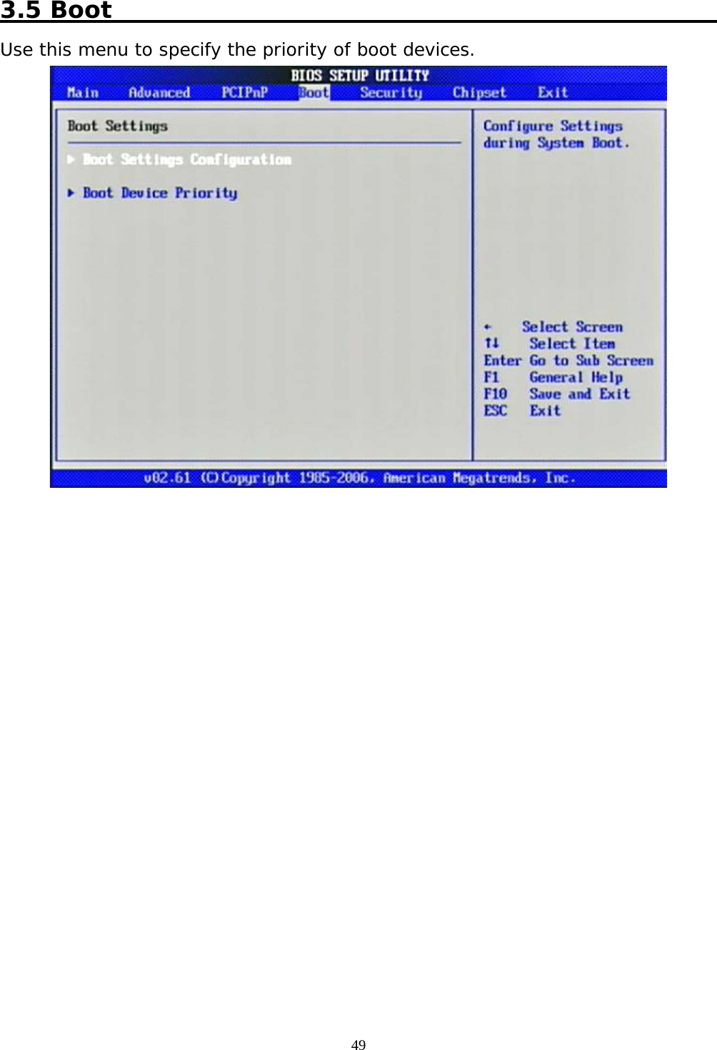
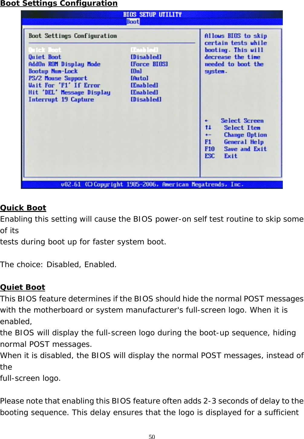
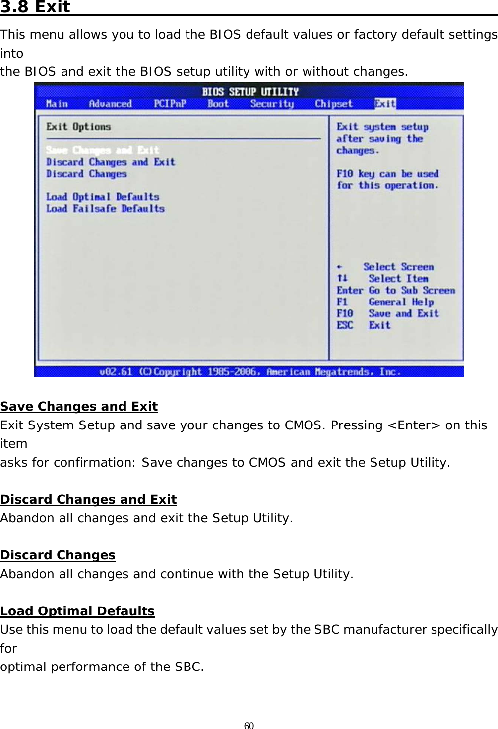
![51 amount of time. Therefore, it is recommended that you disable this BIOS feature for a faster boot-up time. The choice: Disabled, Enabled. AddOn ROM Display Mode This item is used to determine the display mode when an optional ROM is initialized during POST. When set to [Force BIOS], the display mode used by AMI BIOS is used. Select [Keep Current] if you want to use the display mode of optional ROM. The choice: Force BIOS, Keep Current. Bootup Num-Lock This setting is to set the Num Lock status when the system is powered on. Setting to [On] will turn on the Num Lock key when the system is powered on. Setting to [Off] will allow users to use the arrow keys on the numeric keypad. The choice: Off, On. PS/2 Mouse support Select [Enabled] if you need to use a PS/2-interfaced mouse in the operating system. The choice: Disabled, Enabled, Auto. Wait For ‘F1’ If Error When this setting is set to [Enabled] and the boot sequence encounters an error, it asks you to press F1. If disabled, the system continues to boot without waiting for you to press any keys. The choice: Disabled, Enabled. Hit ‘DEL’ Message Display Set this option to [Disabled] to prevent the message as follows:](https://usermanual.wiki/Portwell/WISP5/User-Guide-3627642-Page-51.png)
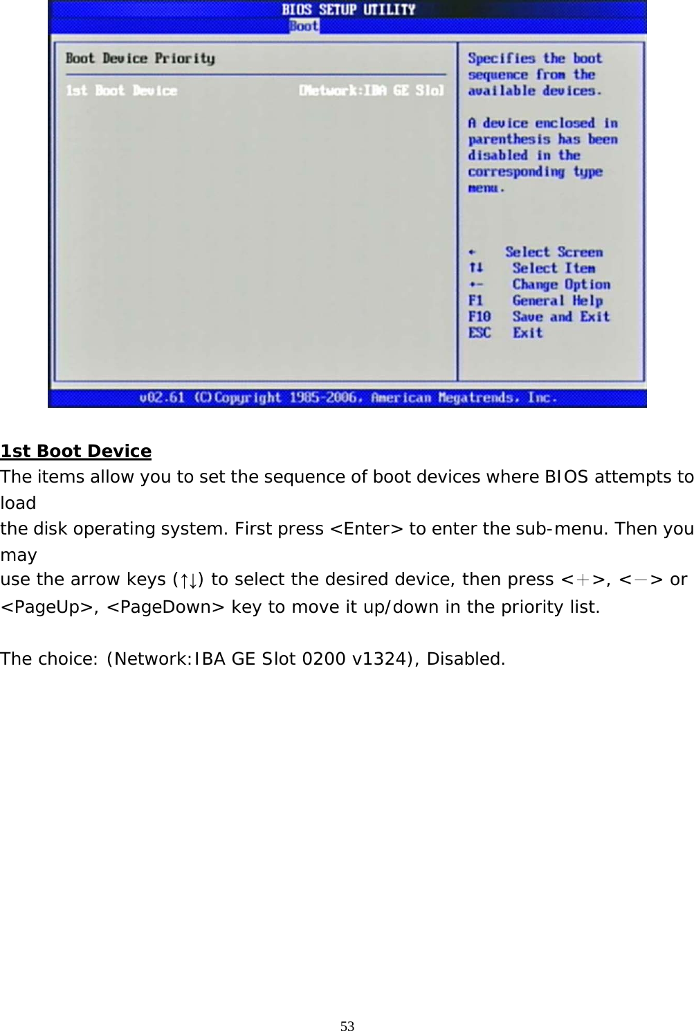
![52 Hit Del if you want to run setup It will prevent the message from appearing on the first BIOS screen when the computer boots. Set it to [Enabled] when you want to run the BIOS Setup Utility. The choice: Disabled, Enabled. Interrupt 19 Capture Interrupt 19 is the software interrupt that handles the boot disk function. When enabled, this BIOS feature allows the ROM BIOS of these host adaptors to "capture" Interrupt 19 during the boot process so that drives attached to these adaptors can function as bootable disks. In addition, it allows you to gain access to the host adaptor's ROM setup utility, if one is available. When disabled, the ROM BIOS of these host adaptors will not be able to "capture" Interrupt 19. Therefore, you will not be able to boot operating systems from any bootable disks attached to these host adaptors. Nor will you be able to gain access to their ROM setup utilities. The choice: Disabled, Enabled. Boot Device Priority](https://usermanual.wiki/Portwell/WISP5/User-Guide-3627642-Page-52.png)
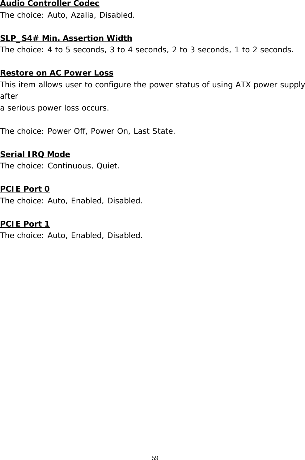
![58 SMPTE295M, SMPTE296M, CEA 7702, CEA 7703. South Bridge Chipset Configuration USB Functions This setting specifies the function of the onboard USB controller. The choice: Disabled, 2 USB Ports, 4 USB Ports, 6 USB Ports. USB 2.0 Controller Set to [Enabled] if you need to use any USB 2.0 device in the operating system that does not support or have any USB 2.0 driver installed, such as DOS. The choice: Enabled, Disabled. USB Client Controller The choice: Enabled, Disabled. SDIO controller The choice: Enabled, Disabled.](https://usermanual.wiki/Portwell/WISP5/User-Guide-3627642-Page-58.png)