Portwell WISP5 Wireless Service Platform User Manual WISP
Portwell, Inc. Wireless Service Platform WISP
Portwell >
User manual
1
WISP Medical PC
User’s Manual
Version 1.6
2
Contents
Copyright Notice......................................................................3
Declaration of Conformity.........................................................3
Chapter 1- General Information
1.1 Packing Contents................................................................4
1.2 System Specifications ........................................................5
1.3 System Overview...............................................................6
1.3.1 Front Side.................................................................6
1.3.2 Rear Side..................................................................6
1.3.3 Left Side...................................................................7
1.4 Dimensions.......................................................................8
1.5 Cleaning and Disinfecting…………………………………………………………….9
1.6 Additional Information and Assistance………………………………………10
1.7 System Setting…………………………………………………………………………..10
1.8 Power On Problems…………………………………………………………………….11
1.9 Install a Wall Mount…………………………………………………………………..12
Chapter 2- Locating Controls and Driver Installations
2.1 Locating Controls……………………………………………………………………….13
2.1.1 Front Panel..............................................................13
2.1.2 Rear I/O..................................................................14
2.2 Driver Installation.............................................................15
2.2.1 Chipset Component Driver Installation.........................15
2.2.2 Intel Graphics GMCH Chip Driver Installation................19
2.2.3 Realtek Gigabit Ethernet Controller Driver Installation….22
2.2.4 MCS7832 USB Ethernet Controller Driver Installation…….24
2.2.5 Wireless Driver Installation........................................27
Chapter 3- BIOS Setup Information
3.1 Entering Setup…………………………………………………………………………..30
3.2 Main Menu………………………………………………………………………………….32
3.3 Advanced……………………………………………………………………………………33
3.4 PCIPnP…………………………………………..…………………………………………..47
3.5 Boot…………………………………….…………………………………………………….51
3
3.6 Security………………………………………………………………………………………54
3.7 Chipset……………………………………………………………………………………….55
3.8 Exit……………………………………………………………………………………………..60
Chapter 4- Appendex
4.1 Protective Packing………………………………………………………………………62
4.2 FCC Caution……………………………………………………………………………….63

4
Copyright Notice
The material in this document is the intellectual property of
Portwell ,Inc. We take every care in the preparation of this
document, but no guarantee is given as to the correctness of its
contents. Our product is under continual improvement and we shall
reserve the right to make changes without notice.
Declaration of Conformity
EMC
CE/FCC Class B
This equipment complies with Part 15 of the FCC Rules. Operation is
subject to the following two conditions:
1. This equipment may not cause harmful interference.
2. This equipment must accept any interference that may cause
undesired operation.
Applicable Standards:
EN 55022: 2006 + A1: 2007, Class B
EN 61000-3-2: 2006
EN 61000-3-3: 1995 + A1: 2001 + A2: 2005
EN 55024: 1998 + A1: 2001 + A2: 2003
IEC 61000-4-2: 2008
IEC 61000-4-3: 2006 + A1: 2007
IEC 61000-4-4: 2004
IEC 61000-4-5: 2005
IEC 61000-4-6: 2007
IEC 61000-4-8: 1993 + A1: 2000
IEC 61000-4-11: 2004
FCC 47 CFR Part 15 Subpart
ICES-003 Issue 4
ANSI C63.4-2003
Safety
Applicable Standards:
EN 60601-1
UL 60601-1
5
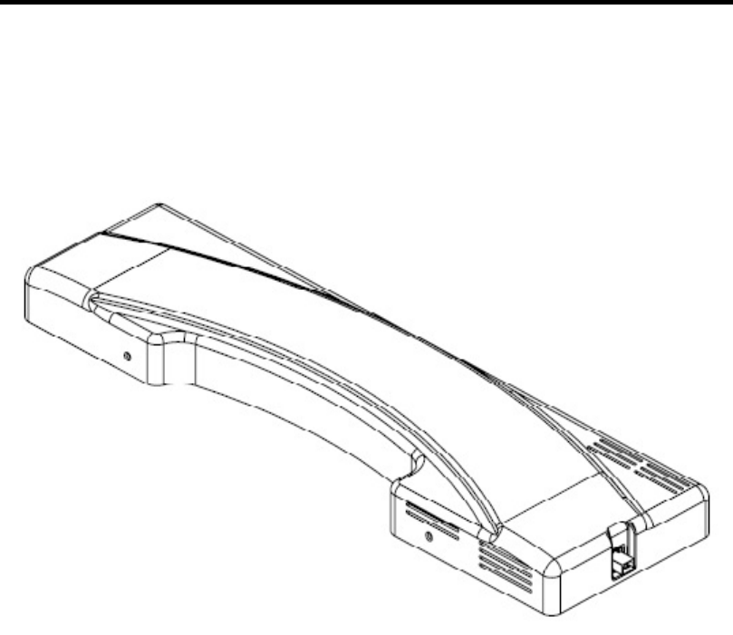
Chapter 1
General Information
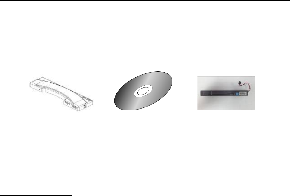
1.1 P
acking Contents
Following illustration displays the package contents of WISP. If any of the
following items is damaged or missed out please contact us right away.
Classification
1. Level of production against electric shock: not classified
2. Level of protection against the ingress of water: IPX0
3. Type of protection against: Power by Class I
4. Mode of operation: Continuous Operation
WISP
Driver & Utility
Battery Pack
(Option)

6
1.2 System Specifications
System
CPU
Intel® Atom™ CPU Z510 1.10GHz FSB:533MHz
L2:512K
Chipset
Intel® System Controller Hub US15W
Graphics Controller
Intel Graphics Media Accelerator 500
Memory
Transcend DDR2 533 1GB SODIMM
Storage
Transcend 16GB CF
Operation System
Windows Embeddad 2009
Peripherals & Devices
USB Port
USB Port x 2
Connectivity
RTL 8111C GbE LANs
WLAN 802.11 a/b/g/n support
MCS7830 USB Enternet support
Power Source
Internal SNP-Z057 (60W, Medical Level)
Power Input
100-240 Vac, 47-63 Hz, Max. 60 W
Button
Wireless on/off button
Mechanical & Environmental
Operating Temp
0 ~ 40°C
Vibration
5 grms/5 ~ 500Hz/random operation
Shock
10G/peak (11ms)
Regulatory
CE,FCC Class-B
EN60601-1
UL60601-1
Dimensions
530x41x155
Net Weight
10.5Kg
7
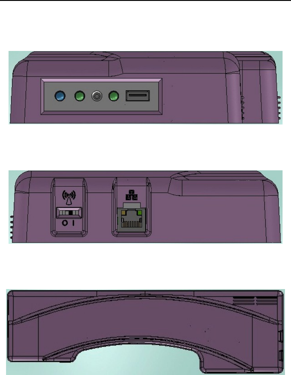
1.3 System Overview
1.3.1 Front Side
1.3.2 Rear Side
1.3.3 Left Side
8
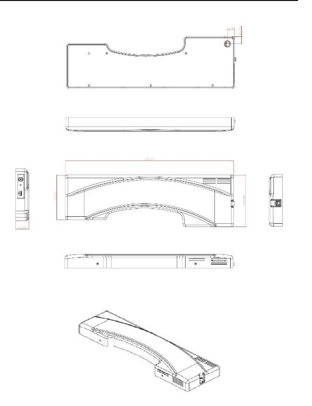
1.4 Dimensions

9
1.5 Cleaning and Disinfecting
Do not use sharp tools.
Never immerse electrical connectors in water or other liquids. Such
actions may damage the device.
If you accidentally spill liquid on a device, disconnect the unit from the
power source.
Contact your service personnel regarding the continued safety of the
unit before placing it back in operation.
Do not spray cleaning agent on the chassis.
Do not use disinfectants that contain phenol.
Do not autoclave or clean the device or its peripherals with strong
aromatic, chlorinated, ketene, ether, or Esther solvents, sharp tools or
abrasives.
During normal use of the WiSP may become soiled and should, therefore,
be cleaned regularly.
Cleaning instructions follow:
1. Wipe the WiSP with a clean cloth that has been moistened in the
cleaning solution.
2. Prepare agent per manufacturer’s instructions or hospital protocol.
Wipe thoroughly with a clean cloth.

10
1.6 Additional Information and Assistance
Contact your distributor, sales representative, or Portwell’s customer
service center for technical support if you need additional assistance.
Please have the following information ready before you call:
1. Product name and serial number
2. Description of your peripheral attachments
3. Description of your software (operating system, version, application
software, etc.)
4. A complete description of the problem
5. The exact wording of any error messages
6. This equipment is a source of electromagnetic waves. Before use
please, make sure that there are not EMI sensitive devices in its
surrounding which may malfunction therefore.
Manufacturer
Portwell, Inc.
Add: No. 242, Bo-Ai Street, Shu-Lin Dist., New Taipei City 238, Taiwan.
Tel: +886-2-7731-8888
Fax: +886-2-7731-9888
1.7 System Setting ___________________________
WiSP is terminal control system of the network none has VGA
display. Must be connected via Ethernet cable to the internal system.
Must be to trained service personnel of the install and
setting.
11
1.8 Power-On Problems_______________________
If the system does not boot after you have applied power, check the
following factors that might have caused the boot failure.
• The external power cord may be loosely connected.
• Loose or improperly connected internal power cables.
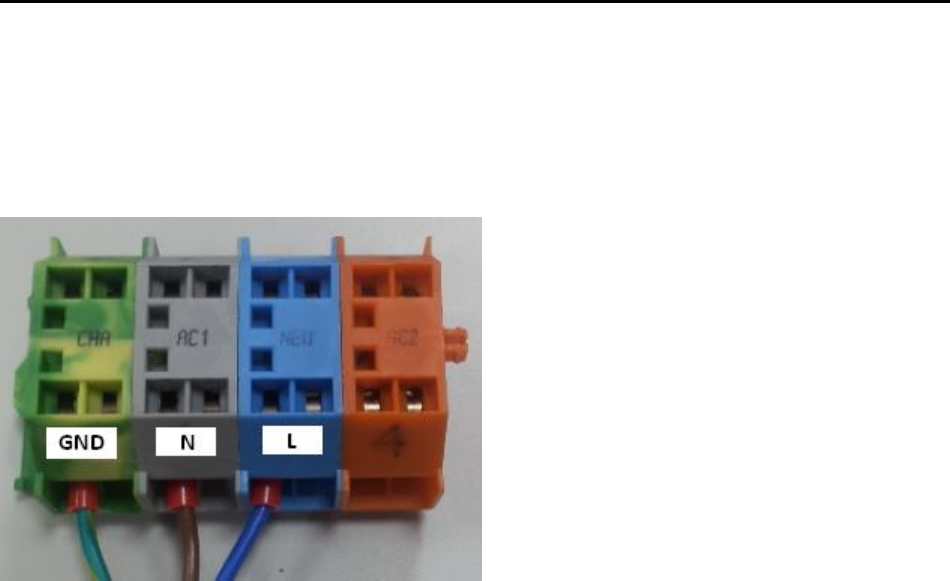
Note: Do not remove the grounding cable.
12
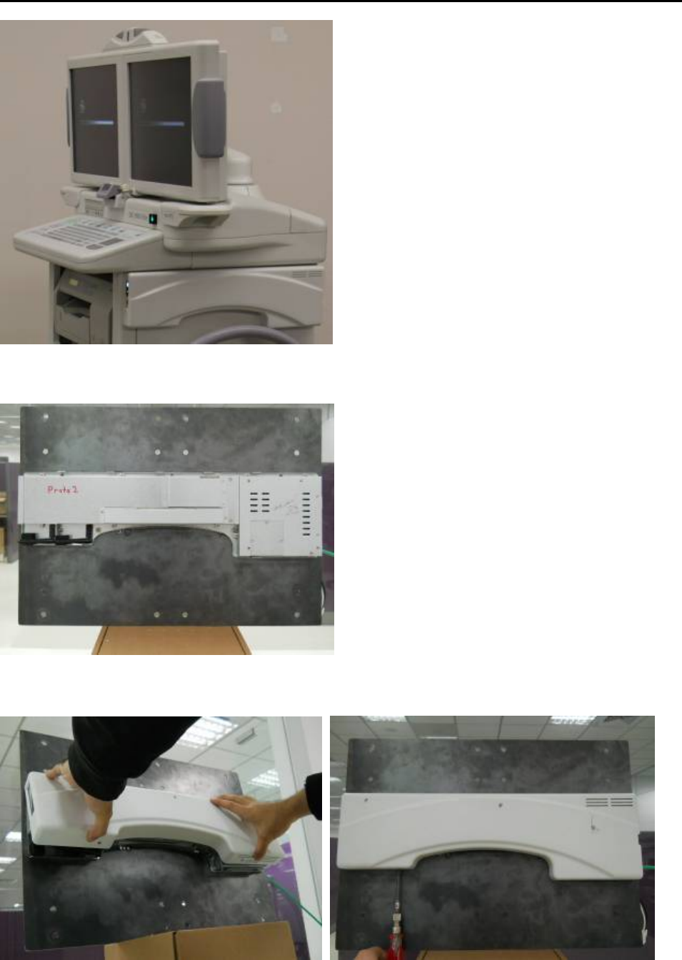
1.9 Install a Wall Mount_______________________
Set 1. Using the included screws, find the ones that match the wall
mount screw holes on the right of system.
Set 2. Close the cover and need to use a screw driver to tighten down the
screw at the bottom.
13
Chapter 2
Locating Controls and Driver installations
2.1
Location Controls
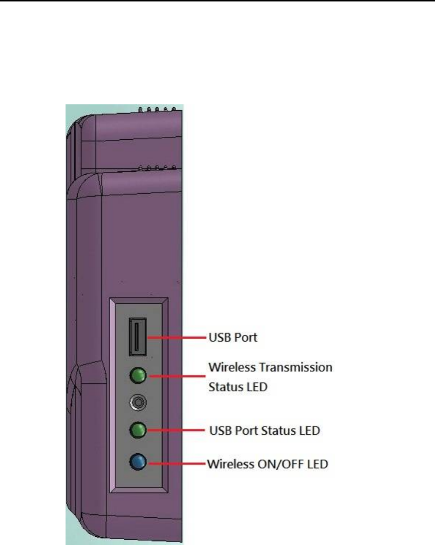
2.1.1 Front Panel
The front panel contains wireless ON/OFF LED, USB port and wireless status LED
14
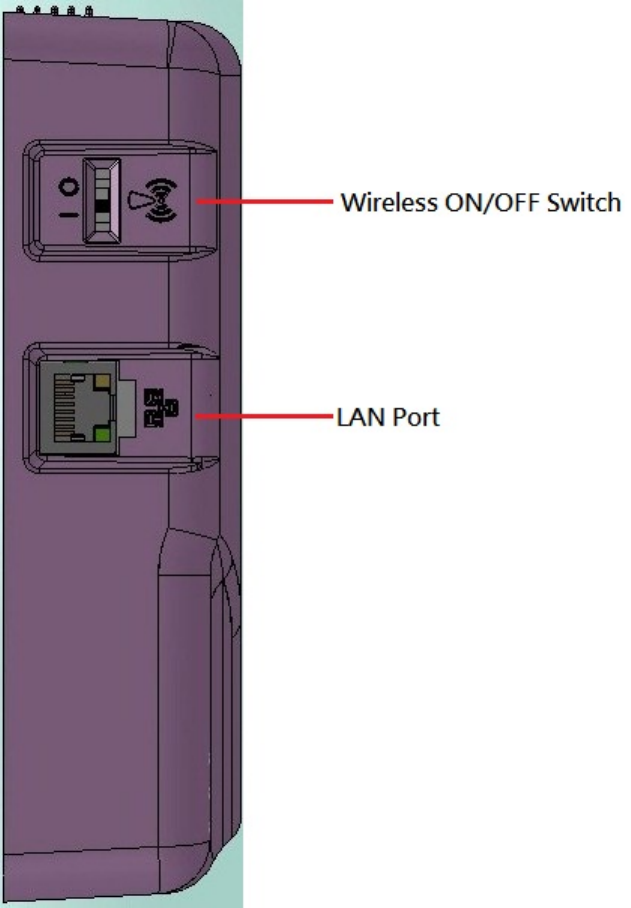
2.1.2 Rear I/O
The Rear I/O side contains LAN port and Wireless switch.
15
2.2 Driver Installation
Before you install the drivers, you must make sure the Operating System, in this
case, Windows XP) is installed first.
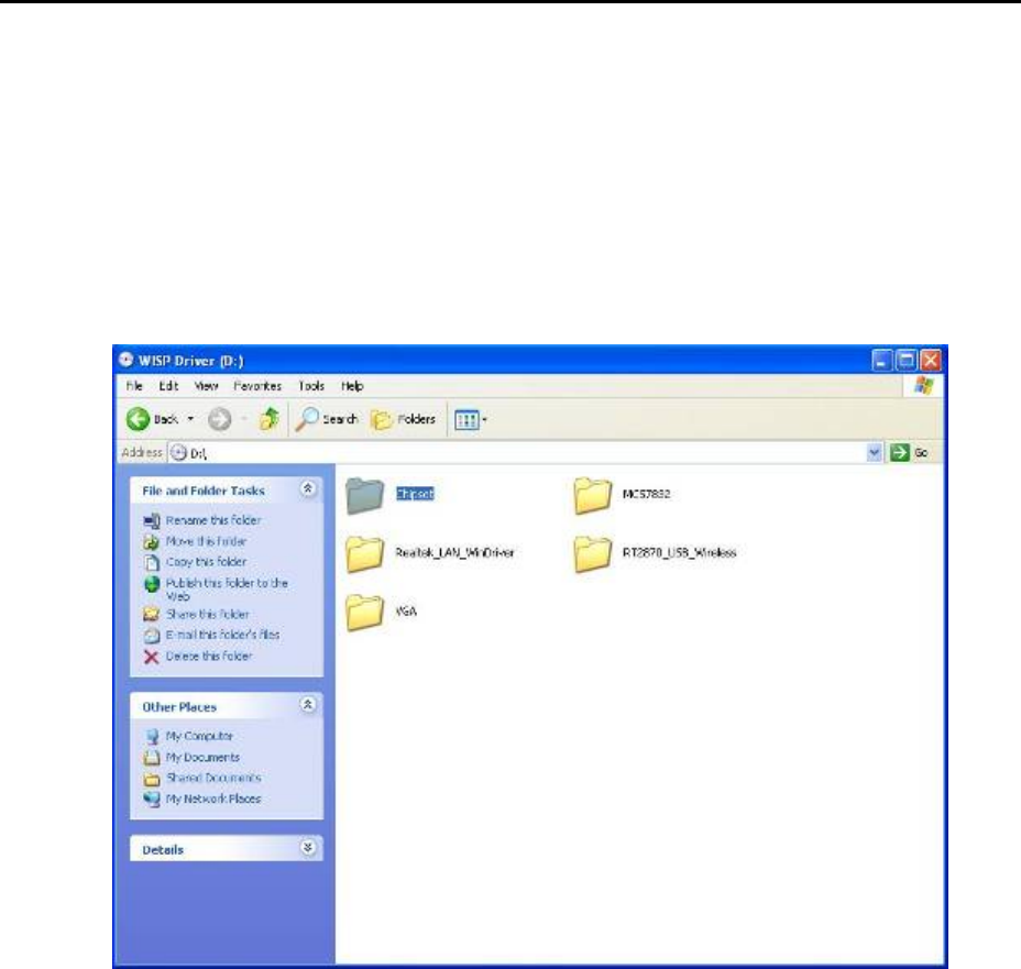
2.2.1 Chipset Component Driver Installation
1. Put the CD ROM into the CD-ROM drive, Click Chipset directory to
install the device driver.
16
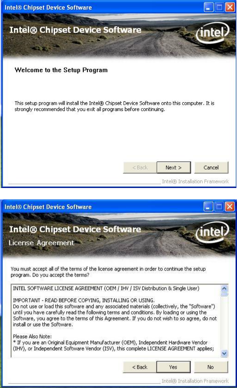
2. Make sure you have closed all programs running and then click
Next to continue
3. Please read the license agreement first, and click Yes to continue.
17
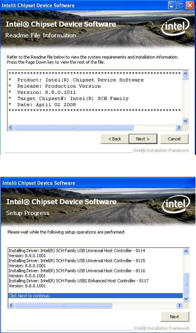
4. Please read the Readme file for system requirements and
installation information, and click Next to continue.
5. The chipset device driver installation is completed. Click Next to
continue.
18
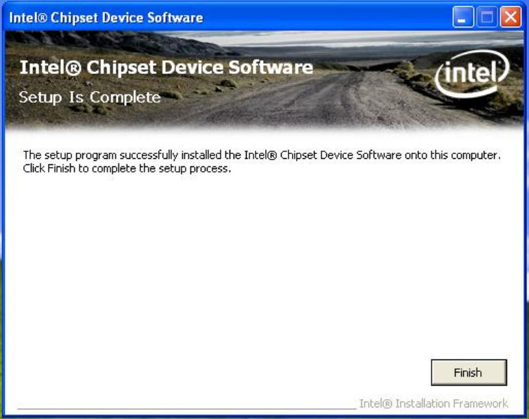
6. To have the installation take effect, select the Yes radio button and
click Finish to restart your computer.
19
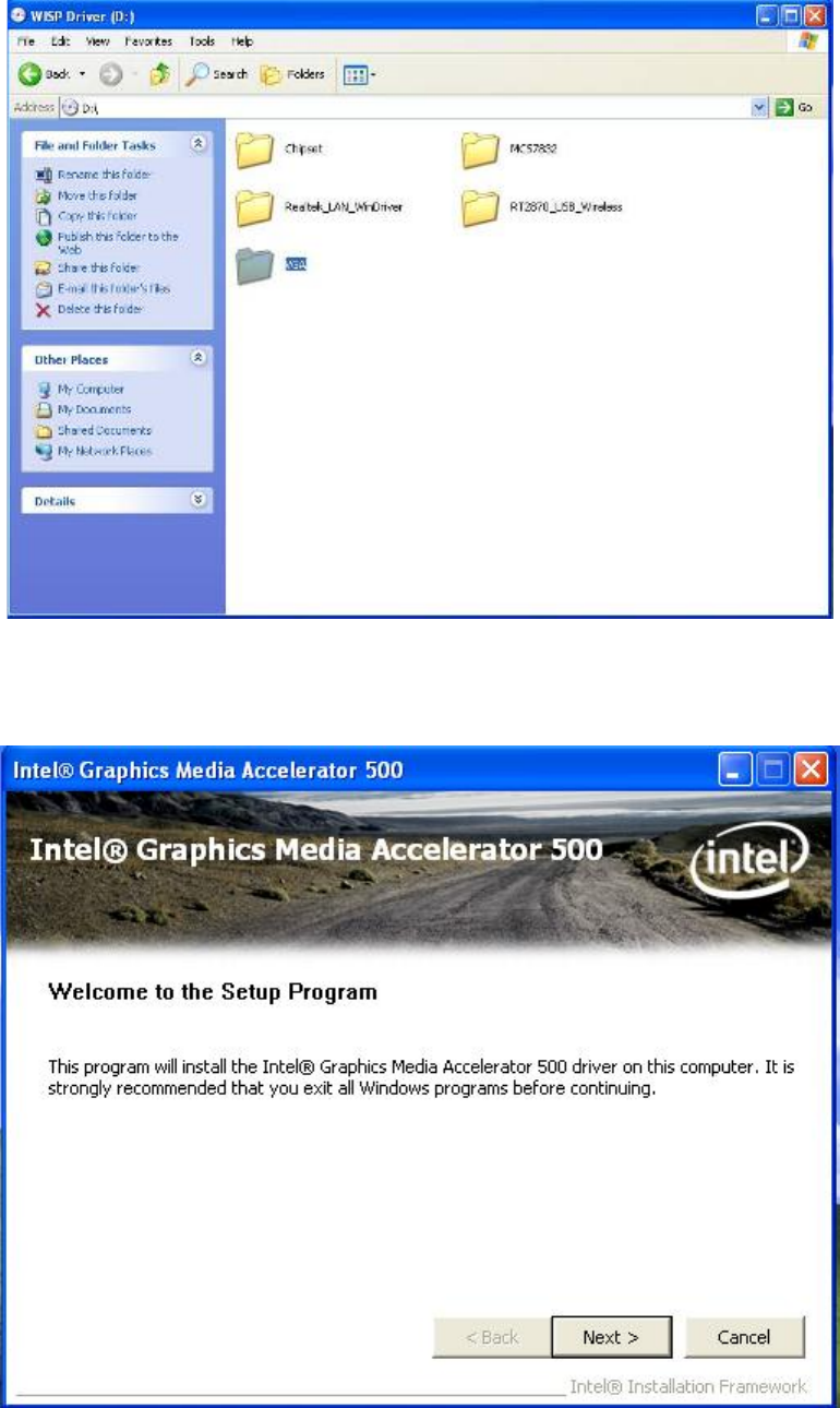
2.2.2 Intel Graphics GMCH Chip Driver Installation
1. Click VGA directory to install the device driver.
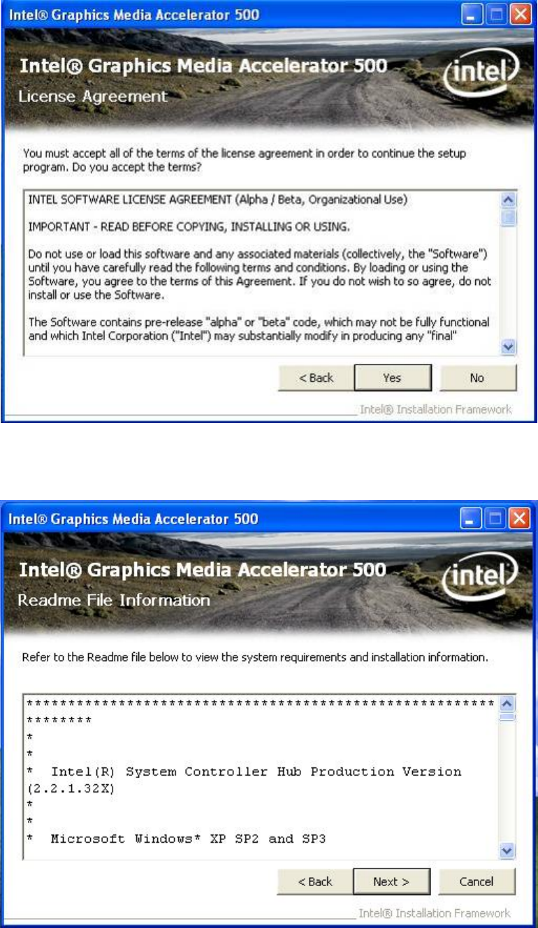
2. Make sure you have closed all programs running and then click
Next to continue.
20
3. Please read the license agreement first, and click Yes to continue.
4. Please read the Readme file for system requirements and
installation information, and click Next to continue.
21
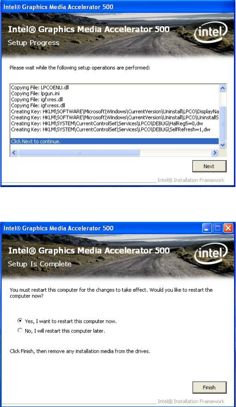
5. Please wait for a while for the data extracting and file copying.
6. After installing the graphics device driver, click Finish with Yes
radio button selected to restart your computer.
22
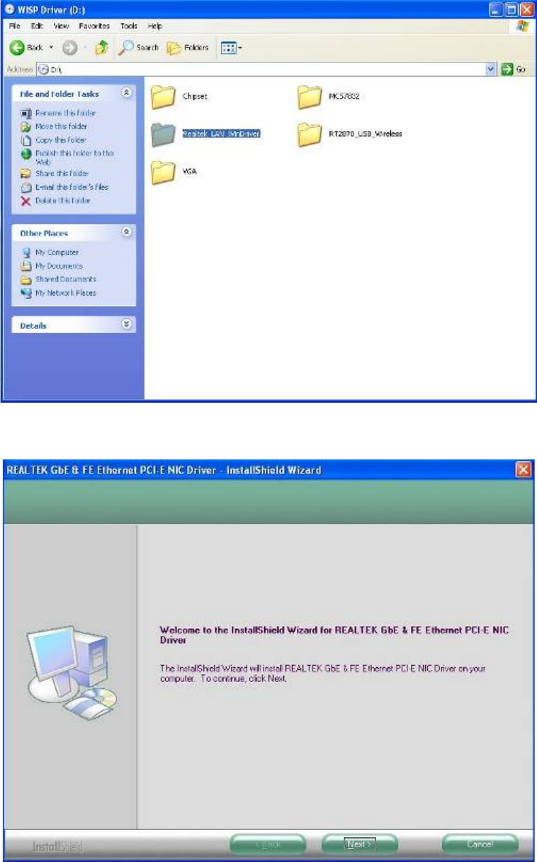
2.2.3 Realtek Gigabit Ethernet Controller Driver Installation
1. Click Realtek_LAN_WinDriver directory to install the device
driver.
2. Click Next to continue.
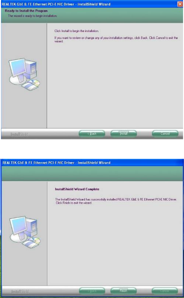
23
3. Click Install to start installation.
4. Click Finish to close the wizard window.
24
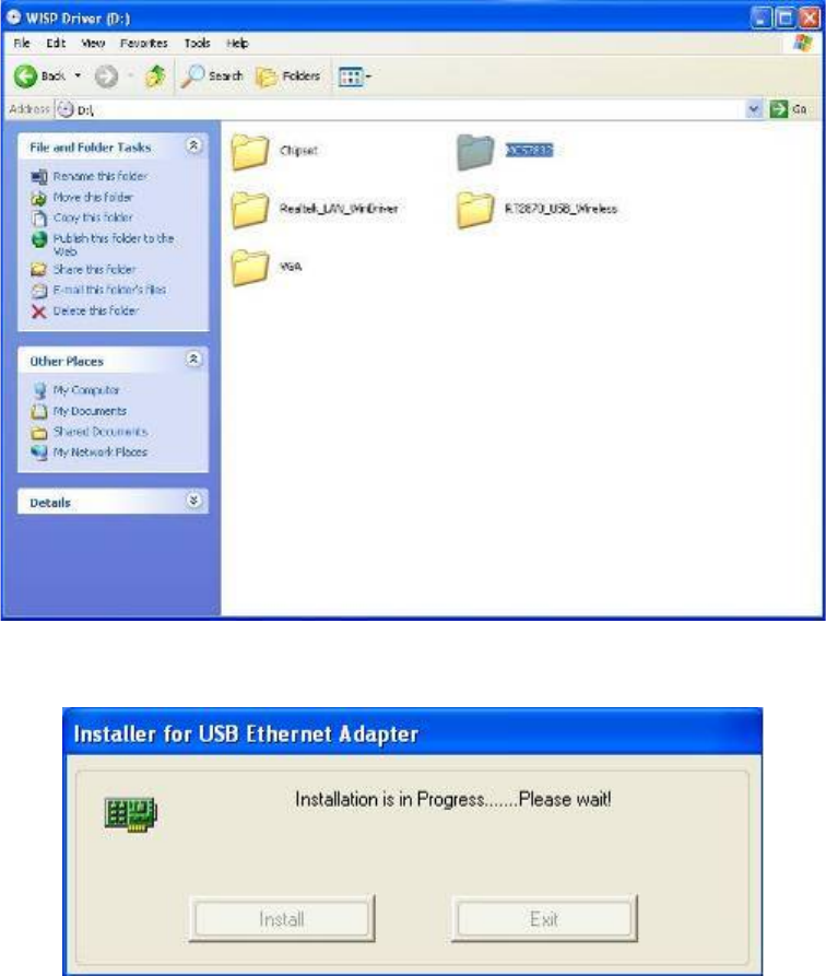
2.2.4 MCS7832 USB Ethernet Controller Driver Installation
1. Click MCS7832 directory to install the device driver.
2. Auto install for USB Ethernet
25
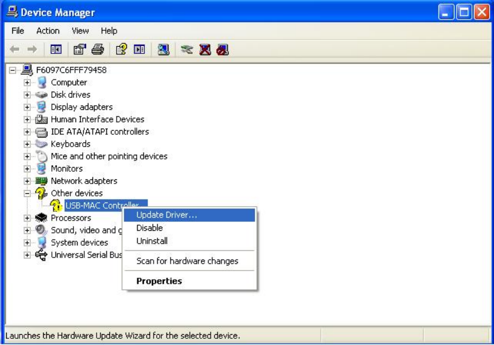
3. After the driver is installed, the USB Ethernet device information in
Device Manager may appear with an exclamation mark. To solve this
problem, please go through the following few steps to manually
update the driver for this device on the Device Manager”. You just
need to do it once.
Double left-click the mouse on the “USB Device” icon under the
“USB –MAC Controller” icon to update driver.
26
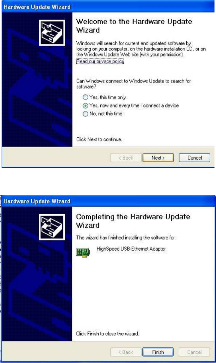
4. You will see the “Hardware Update Wizard” appearing on your
desktop. Please select “Yes, now and every time I connector a
device” and then click “Next”.
5. The driver is now completed updated. Click “Finish”.
27
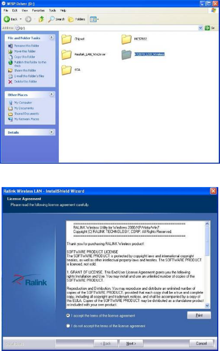
2.2.5 Wireless Driver Installation
1. Click RTL2870_USB_Wireless directory to install the device
driver.
2. Please read the license agreement first, and click Next to continue.
28
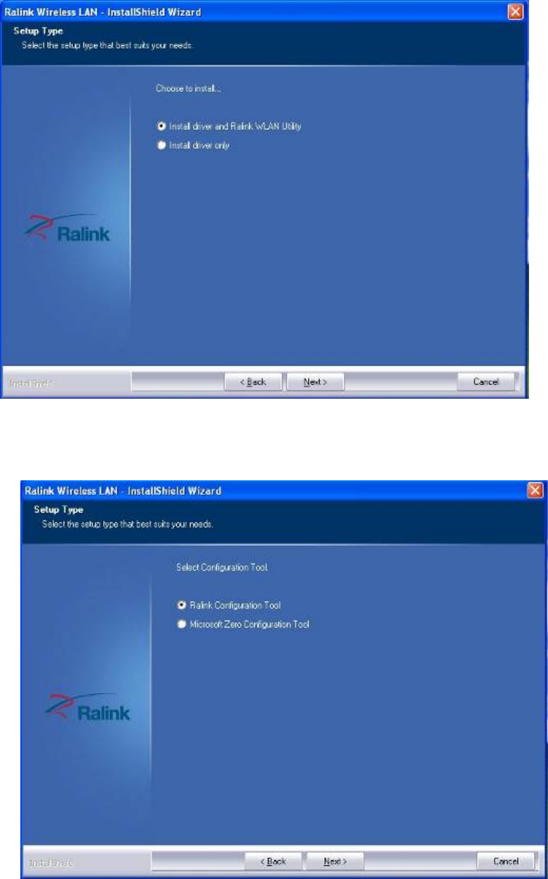
3. Select the setup type, click Next to continue. The default setting is
“Install driver and Ralink WLAN Utility”.
4. Select the configuration Tools type, click Next to continue. The
default setting is “Ralink Configuration Tool”.
29
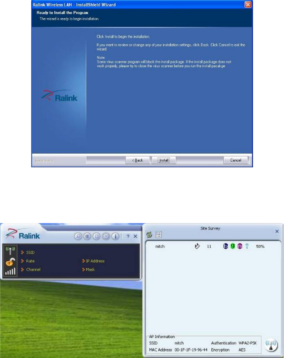
5. The WLAN driver is being installed. When the progress bar reaches
the end, the installation is done.
6. Once the installation is completed, a Wireless LAN window as the
figure shown below will pop up (for installing it the first time). This
windows displays the status of wireless signals and provides setting
options.

30
Chapter 3
BIOS Setup Information
WISP is equipped with the AMI BIOS stored in Flash ROM. These BIOS has a
built-in Setup program that allows users to modify the basic system configuration
easily. This type of information is stored in CMOS RAM so that it is retained during
power-off periods. When system is turned on, NANO-8045L communicates with
peripheral devices and checks its hardware resources against the configuration
information stored in the CMOS memory. If any error is detected, or the CMOS
parameters need to be initially defined, the diagnostic program will prompt the
user
to enter the SETUP program. Some errors are significant enough to abort the
start-up.
3.1 Entering Setup
Turn on or reboot the computer. When the message, “Hit <DEL> if you want to
run
SETUP” appears, press <Del> key to enter BIOS setup program.
If the message disappears before you respond, but you still wish to enter Setup,
please restart the system to try “COLD START” again by turning it OFF and then
ON, or touch the "RESET" button. You may also restart from “WARM START” by
pressing <Ctrl>, <Alt>, and <Delete> keys simultaneously. If you do not press
the
keys at the right time and the system will not boot, an error message will be
displayed
and you will again be asked to,
Press <F1> to Run SETUP or Resume
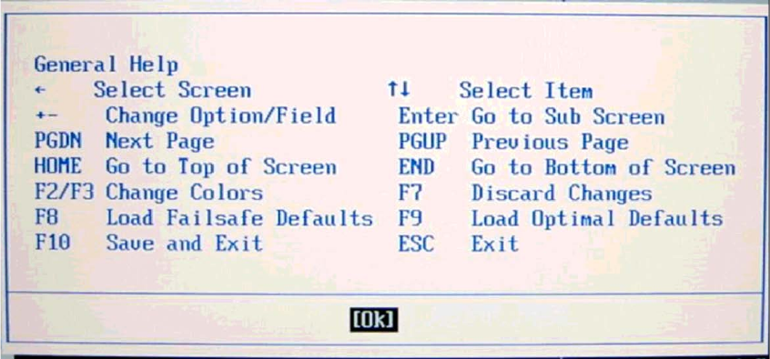
The BIOS setup program provides a General Help screen. You can call up this
screen
from any menu by simply pressing <F1>. The Help screen lists the appropriate
keys
to use and the possible selections for the highlighted item. Press <Esc> to exit
the
Help screen.
31
32
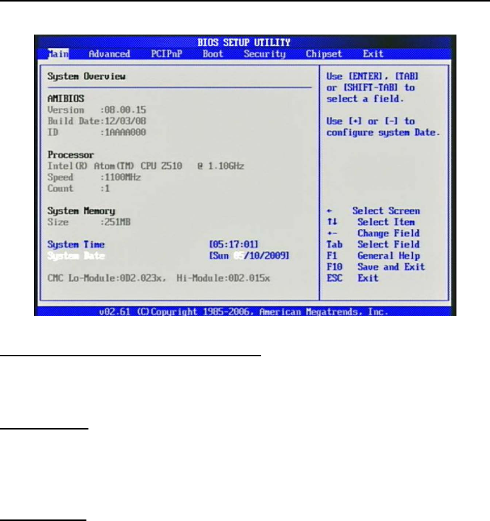
3.2 Main Menu
Use this menu for basic system configurations such as time, date etc.
AMI BIOS, Processor, System Memory
These items show the firmware and hardware specifications of your system. Read
only.
System Time
The time format is <Hour> <Minute> <Second>. Use [+] or [-] to configure
system
Time.
System Date
The date format is <Day>, <Month> <Date> <Year>. Use [+] or [-] to
configure
system Date.
33
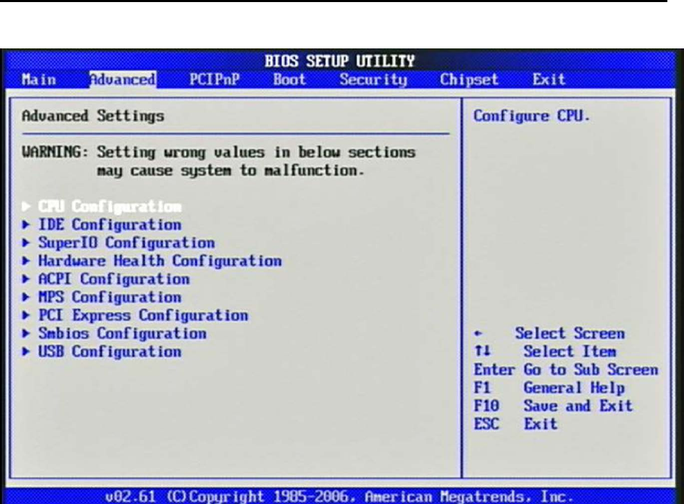
3.3 Advanced
Use this menu to set up the items of special enhanced features.
34
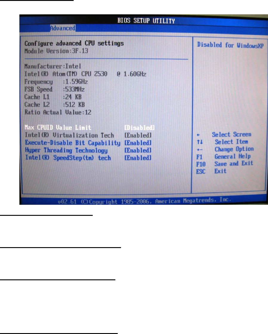
CPU Configuration
These items show the advanced specifications of your CPU. Read only.
Max CPUID Value Limit
Disable for Windows XP.
Execute-Disable Bit Capability
When disable, force the XD feature flag to always return 0.
Hyper Threading Technology
Enable for Windows XP and Linux4 (OS optimized for Hyper Threading
Technology)
and disabled for other OS (OS not optimized for Hyper-Threading Technology)
Intel(R) SpeedSetup(™) tech
Disable: Disable GV3
Enable: Enable GV3
35
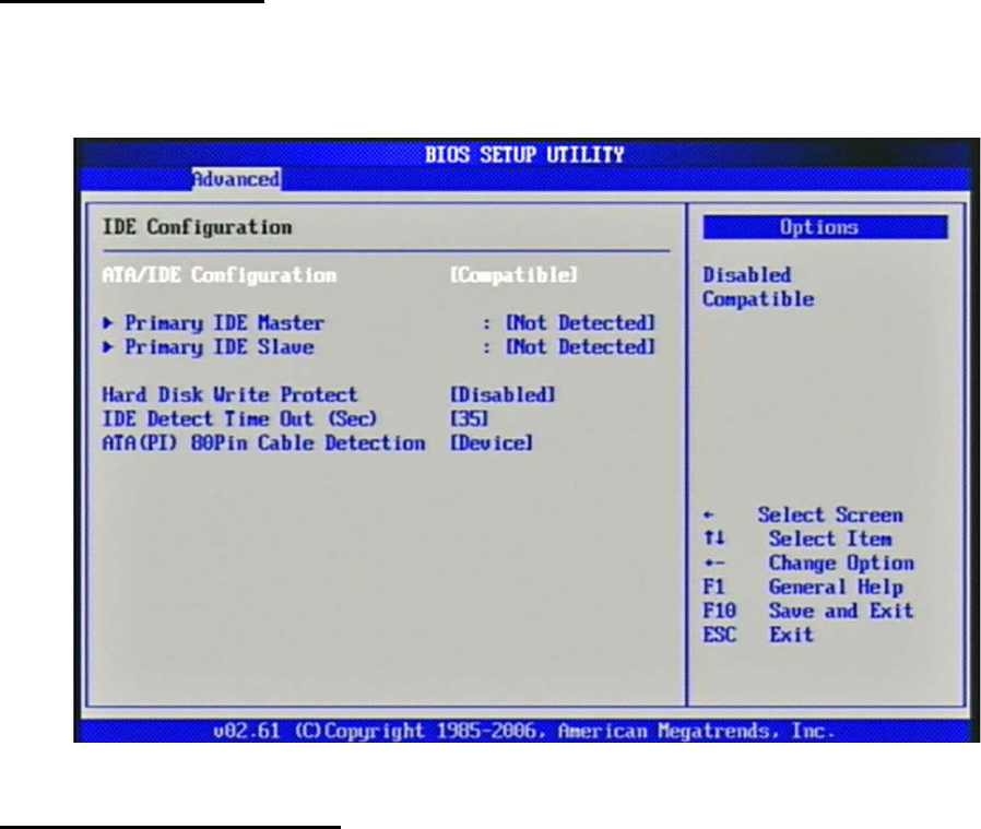
IDE Configuration
The IDE Configuration the IDE devices, such as hard disk drive or CD-ROM drive.
It
uses a separate sub menu to configure each hard disk drive (Master and Slave).
ATA/IDE Configuration
The choice: Disabled, Compatible.
36
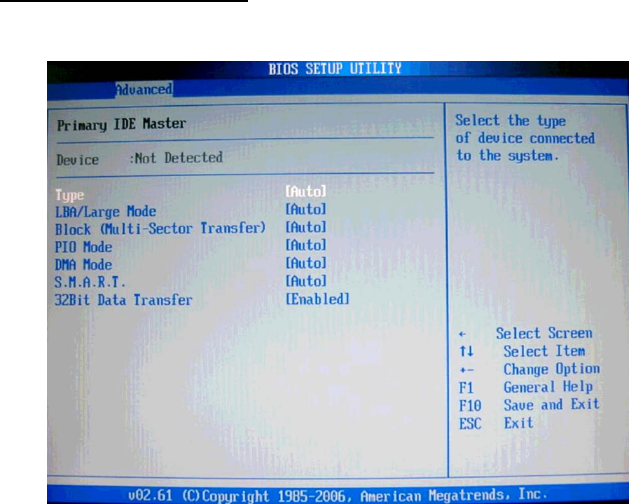
Primary IDE Master/Slave
While entering setup, BIOS auto detects the presence of IDE devices. This display
shows the status of auto detection of IDE devices.
[Type] Press PgUp/<+> or PgDn/<-> to select [Manual], [None] or [Auto]
type.
You can use [Manual] to define your own drive type manually.
[LBA/Large Mode] Enabling LBA causes Logical Block Addressing to be used in
place of Cylinders, Heads and Sectors.
[Block (Multi-Sector Transfer)] Any selection except Disabled determines the
number
of sectors transferred per block.
[PIO Mode] Indicates the type of PIO (Programmed Input/Output).
[DMA Mode] Indicates the type of Ultra DMA.

37
[S.M.A.R.T.] This allows you to activate the S.M.A.R.T. (Self-Monitoring Analysis
&
Reporting Technology) capability for the hard disks. S.M.A.R.T is a utility that
monitors your disk status to predict hard disk failure. This gives you an
opportunity
to move data from a hard disk that is going to fail to a safe place before the hard
disk
becomes offline.
[32 Bit Data Transfer] Enable/Disable 32-bit Data Transfer.
Hard Disk Write Protect
Disabled/Enabled device write protection, this will be effective only if device is
accessed through BIOS.
The choice: Disabled, Enabled.
IDE Detect Time Out (Sec)
Select the time out value for detecting ATA/ATAPI device (s).
The choice: 0, 5, 10, 15, 20, 25, 30, 35.
ATA (PI) 80Pin Cable Detection
Select the mechanism for detecting 80Pin ATA (PI) cable.
The choice: Host & Device, Host, Device.
Super IO Configuration
Serial Port 1 Address
Allows BIOS Select Serial Port1 Base Addresses.
The choice: Disabled, 3F8/IRQ4.
Watch Dog Timer Set
This BIOS testing option is able to reset the system according to the selected
table.
38
The choice: Disabled, 10, 20, 30, 40 Sec, 1Min, 2Min, 4Min.
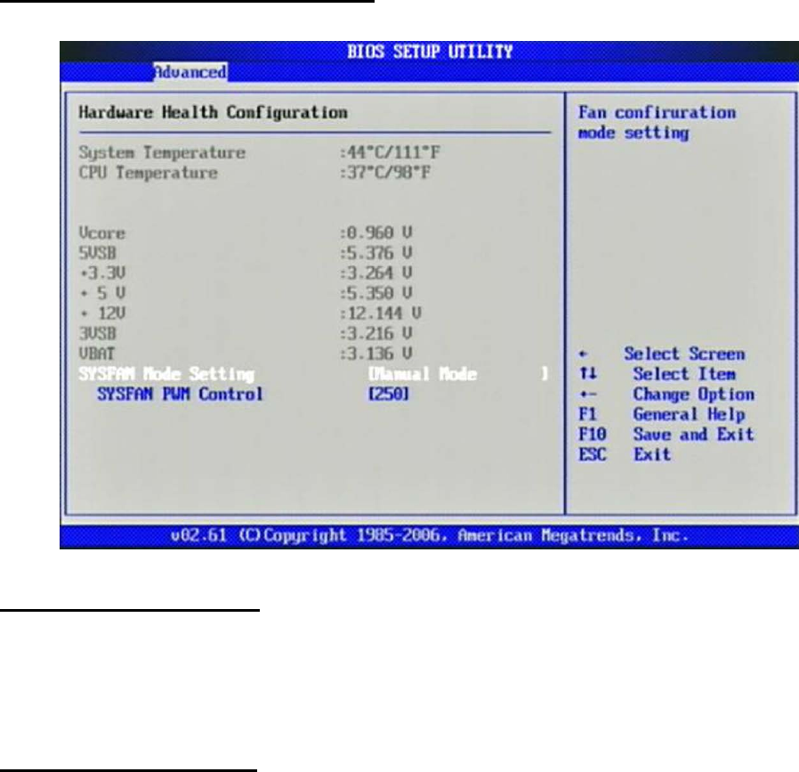
Hardware Health Configuration
Configuration / monitor the Hardware Health.
SYSFAN Mode Setting
Fan configuration mode setting.
The choice: Manual Mode, Thermal Cruise Mode.
SYSFAN PWM Control
The PWM duty cycle control.
The choice: 0 to 255.
39
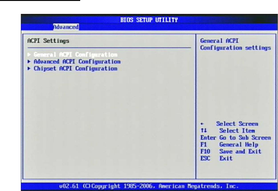
ACPI Configuration
Select for Advanced ACPI Configuration.
40
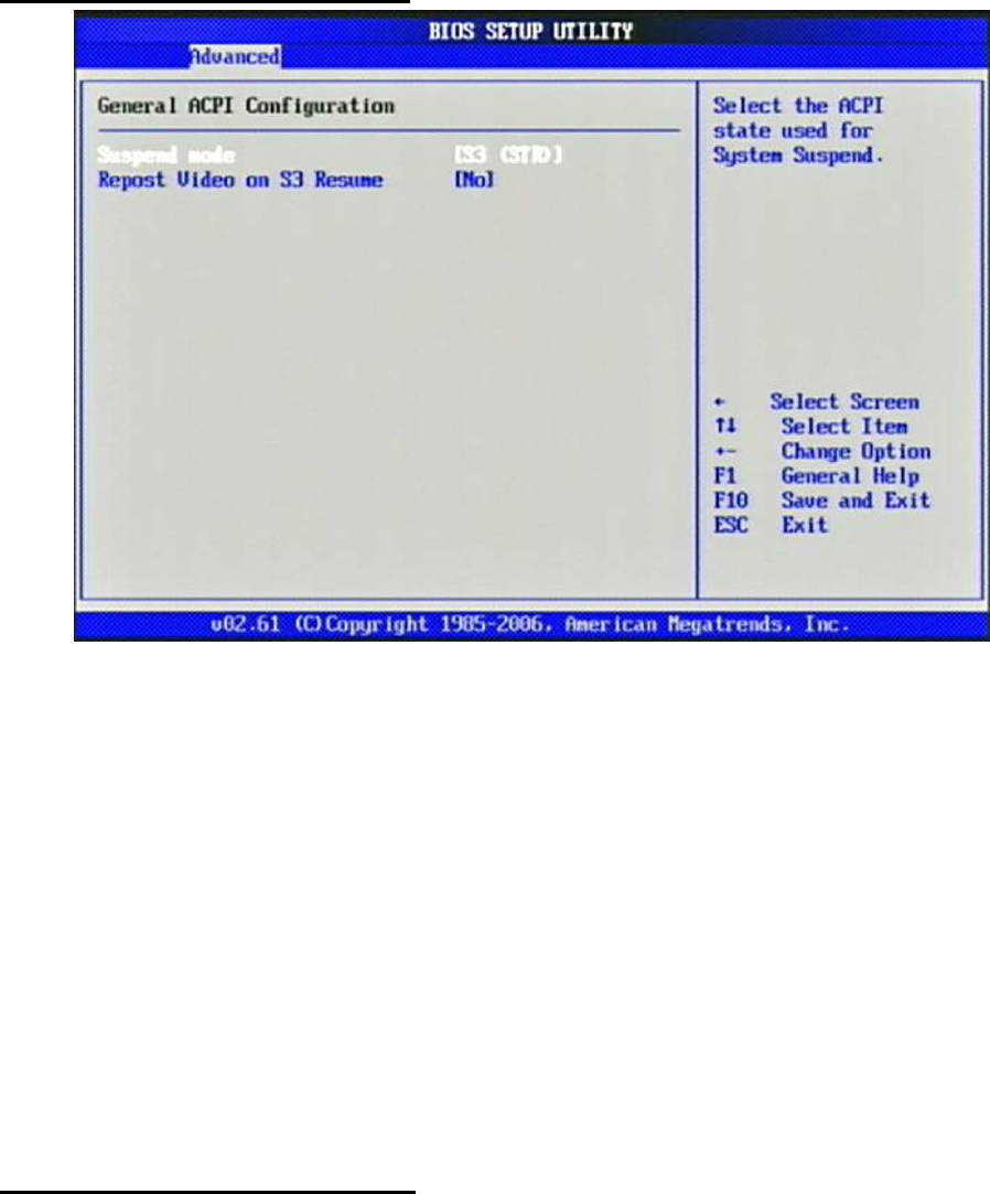
General ACPI Configuration
Suspend mode
This item specifies the power saving modes for ACPI function. If your operating
system supports ACPI, you can choose to enter the Standby mode in S3 (STR)
function through the setting of this field. Option is:
[S3 (STR)] The S3 sleep mode is a lower power state where the information of
system
configuration and open applications/ files is saved to main memory that remains
powered while most other hardware components turn off to save energy. The
information stored in memory will be used to restore the system when a “wake
up”
event occurs.
Repost Video on S3 Resume
Determines whether to invoke VGA BIOS post on S3/STR resume.
The choice: No, Yes
41
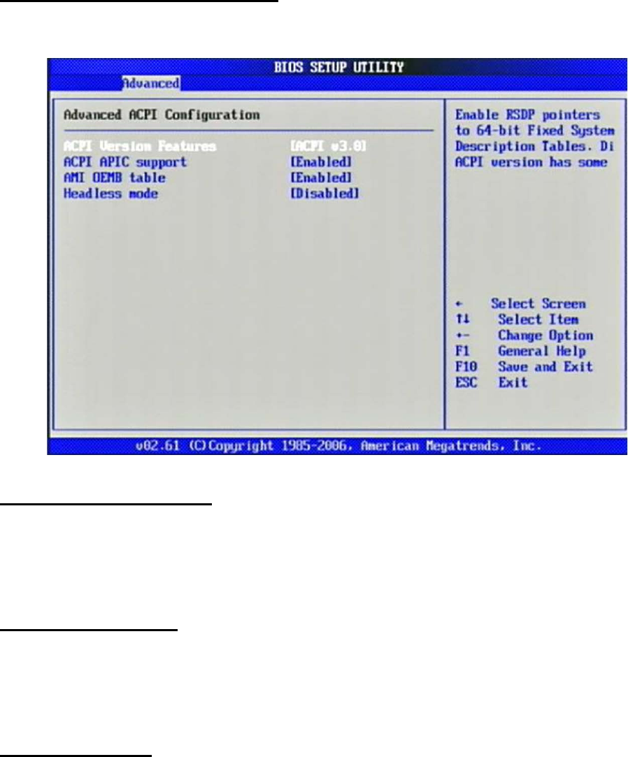
Advanced ACPI Configuration
Advanced ACPI Configuration settings, Use this section to configure additional
ACPI options.
ACPI Version Features
Enable RSDP pointers to 64-bit Fixed System Description Tables.
The choice: ACPI v1.0 / ACPI v2.0 / ACPI v3.0.
ACPI APIC support
Include ACPI APIC table pointer to RSDT pointer list.
The choice: Disabled, Enabled.
AMI OEMB table
Include OEMB table pointer to R(X) SDT pointer list.
The choice: Disabled, Enabled.
42
Headless mode
Enable / Disable Headless operation mode through ACPI.
The choice: Disabled, Enabled.
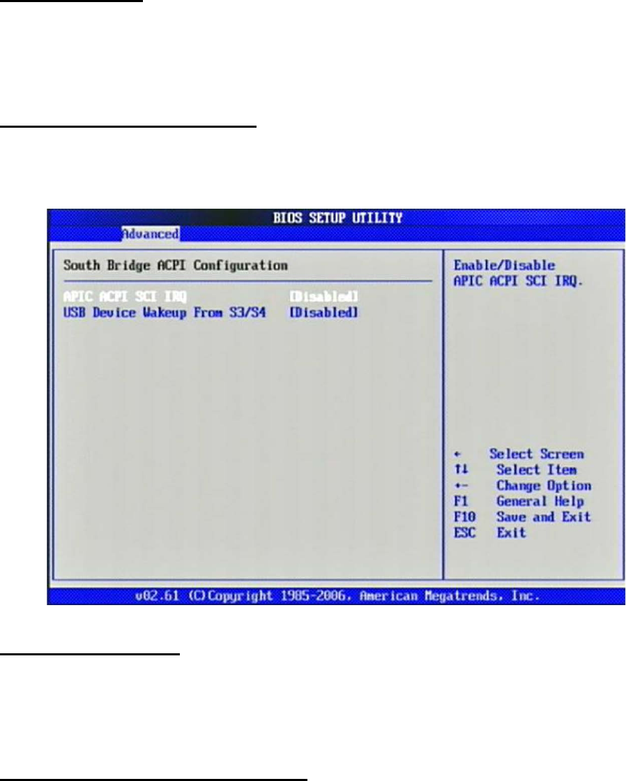
Chipset ACPI Configuration
Chipset ACPI related Configuration settings, Use this section to configure
additional
ACPI options.
APIC ACPI SCI IRQ
Enable / Disable APIC ACPI SCI IRQ.
The choice: Disabled, Enabled.
USB Device Wakeup From S3/S4
Enable / Disable USB device Wake from S3/S4 mode.
The choice: Disabled, Enabled.
43
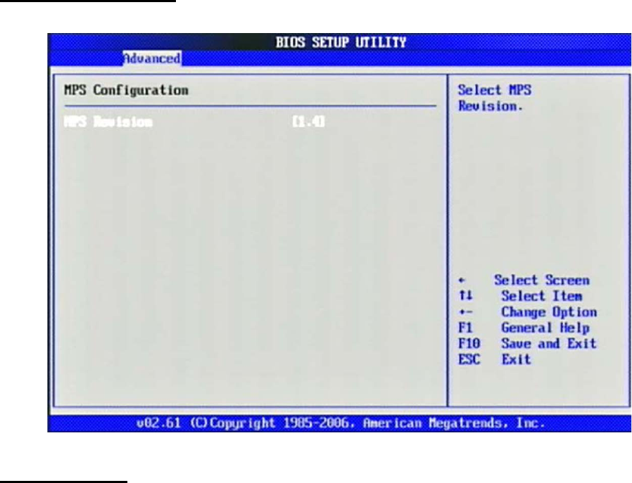
MPS Configuration
Configure the Multi-Processor Table.
MPS Revision
This field allows you to select which MPS (Multi-Processor Specification) version
to
be used for the operating system. You need to select the MPS version supported
by
your operating system. To find out which version to use, consult the vendor of
your
operating system.
The choice: 1.1, 1.4.
44
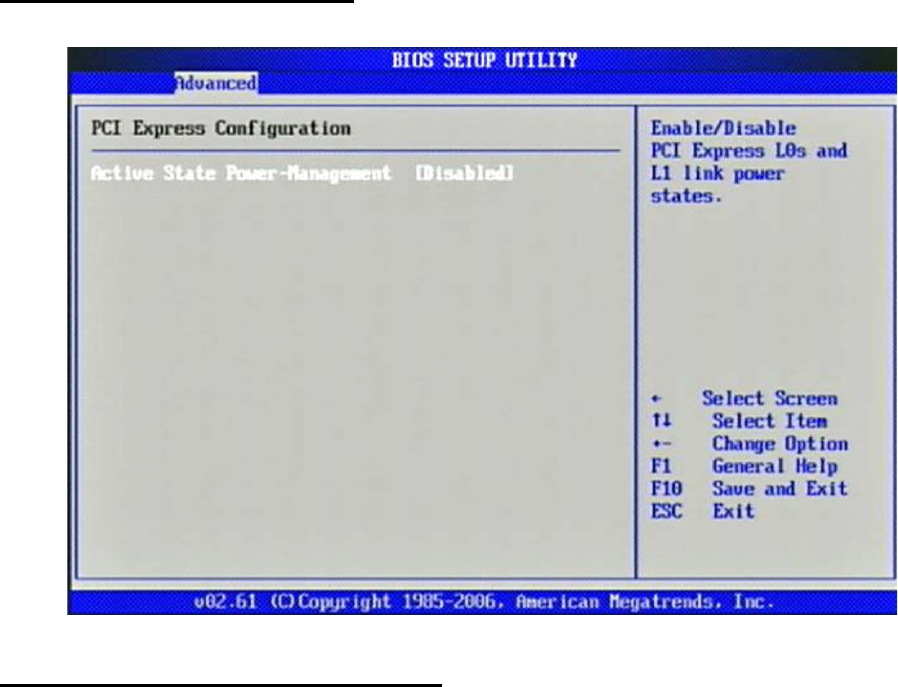
PCI Express Configuration
Configure PCI Express Support.
Active State Power-Management
PCI Express L0s and L1 link power states.
The choice: Disabled, Enabled.
45
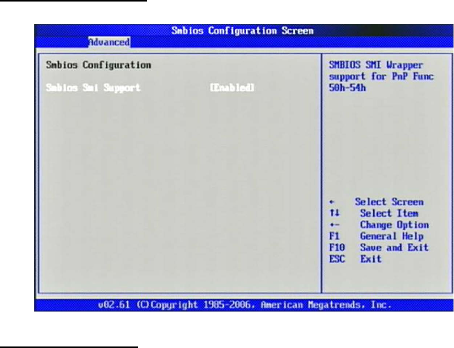
Smbios Configuration
SMBIOS Configuration Menu.
Smbios Smi Support
SMBIOS SMI Wrapper supports for PnP Func 50h-54h.
The choice: Disabled, Enabled.
46
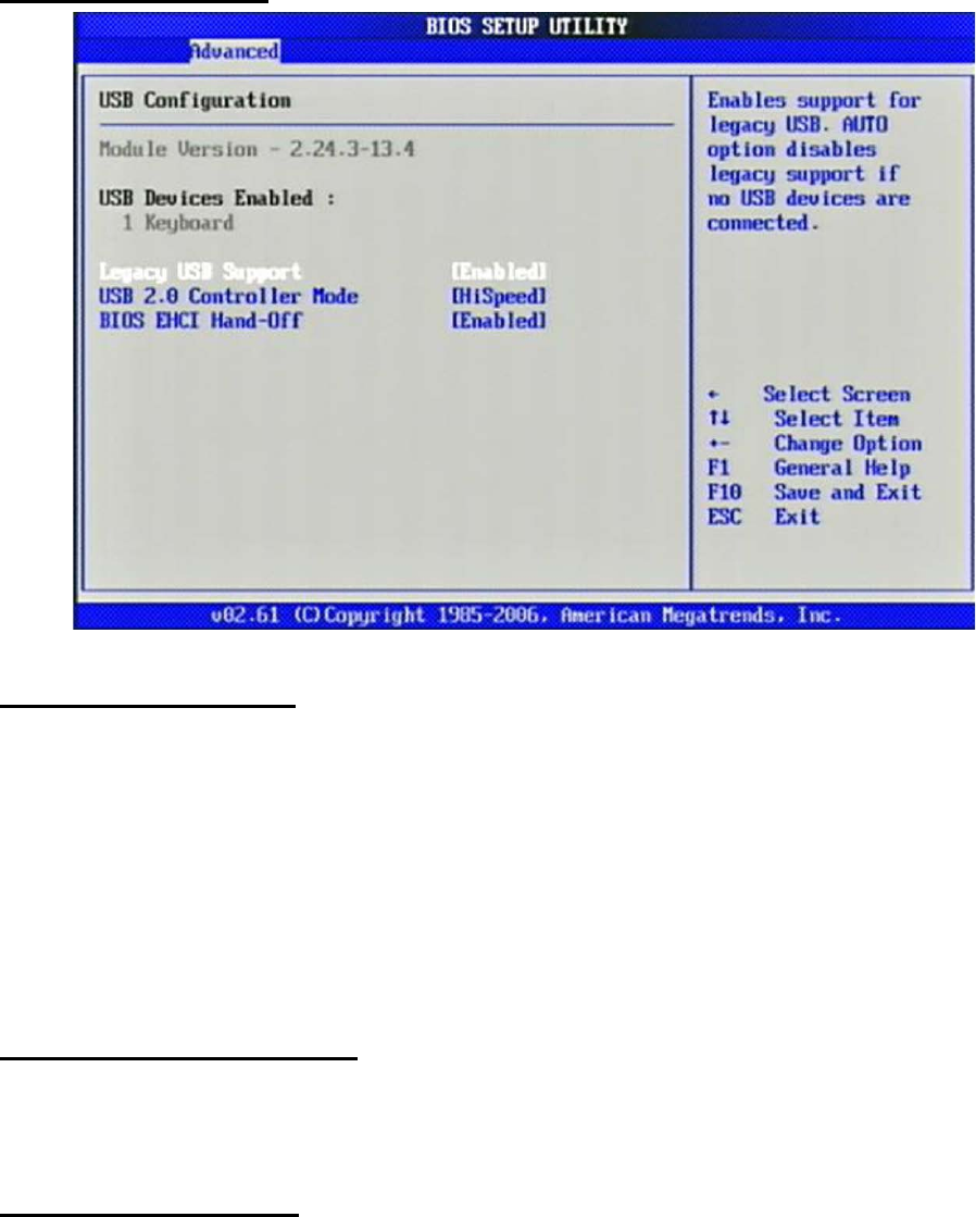
USB Configuration
Legacy USB Support
Set to [Enabled] if you need to use any USB 1.1/2.0 device in the operating
system
that does not support or have any USB 1.1/2.0 driver installed, such as DOS and
SCO
Unix.
The choice: Disabled, Enabled, Auto.
USB 2.0 Controller Mode
This setting specifies the operation mode of the onboard USB 2.0 controller.
The choice: FullSpeed, HiSpeed.
BIOS EHCI Hand-Off
This is a workaround for OSes without EHCI hand-off support. The EHCI
ownership
change should claim by EHCI driver.
The choice: Disabled, Enabled.
47
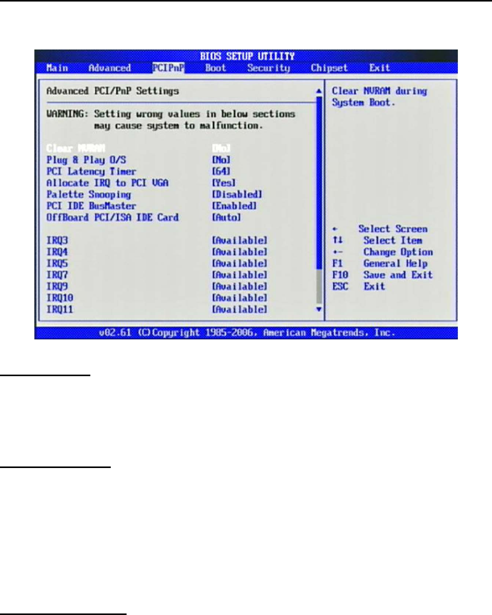
3.4 PCIPnP
Advanced PCI/PnP setting wrong values in below sections may cause system to
malfunction.
Clear NVRAM
Clear NVRAM during System Boot.
The choice: No, Yes.
Plug & Play O/S
No: lets the BIOS configure all the devices in the system.
Yes: lets the operating system configure Plug and Play (PnP) devices not required
for
boot if your system has a Plug and Play operating system.
The choice: No, Yes.
PCI Latency Timer
Select value in units of PCI clocks for PCI device latency timer register.
The choice: 32, 64, 96, 128, 160, 192, 224, 248.

48
Allocate IRQ to PCI VGA
Yes: Assigns IRQ to PCI VGA card if card requests an IRQ.
No: Does not assign IRQ to PCI VGA card even if card requests an IRQ.
The choice: No, Yes.
Palette Snooping
Enabled: informs the PCI devices that an ISA graphics device is installed in the
system so the card will function correctly.
The choice: Disabled, Enabled.
PCI IDE BusMaster
Enabled: Uses PCI bus mastering for reading / writing to IDE drives.
The choice: Disabled, Enabled.
OffBoard PCI/ISA IDE Card
Some PCI IDE cards may require this to be set to the PCI slot number that is
holding
the card. AUTO: Works for most PCI IDE cards.
The choice: Auto, PCI Slot1, PCI Slot2, PCI Slot3, PCI Slot4, PCI Slot5, PCI Slot6.
IRQ 3 / IRQ 4 / IRQ5 / IRQ7 / IRQ 9 / IRQ 10 / IRQ 11 / IRQ 14 / IRQ
15
Available: Specified IRQ is available to be used by PCI/PnP devices.
Reserved: Specified IRQ is reserved for used by Legacy ISA devices.
The choice: Available, Reserved.
Reserved Memory Size
Select Size of memory block to reserve for legacy ISA devices.
The choice: Disabled, 16K, 32K, 64K
49
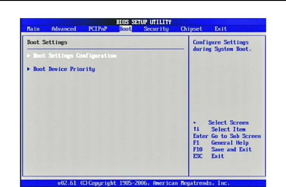
3.5 Boot
Use this menu to specify the priority of boot devices.
50
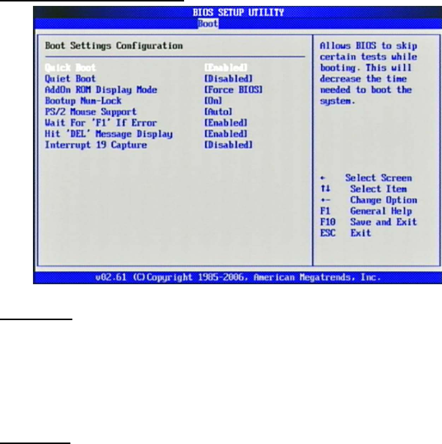
Boot Settings Configuration
Quick Boot
Enabling this setting will cause the BIOS power-on self test routine to skip some
of its
tests during boot up for faster system boot.
The choice: Disabled, Enabled.
Quiet Boot
This BIOS feature determines if the BIOS should hide the normal POST messages
with the motherboard or system manufacturer's full-screen logo. When it is
enabled,
the BIOS will display the full-screen logo during the boot-up sequence, hiding
normal POST messages.
When it is disabled, the BIOS will display the normal POST messages, instead of
the
full-screen logo.
Please note that enabling this BIOS feature often adds 2-3 seconds of delay to the
booting sequence. This delay ensures that the logo is displayed for a sufficient

51
amount of time. Therefore, it is recommended that you disable this BIOS feature
for a
faster boot-up time.
The choice: Disabled, Enabled.
AddOn ROM Display Mode
This item is used to determine the display mode when an optional ROM is
initialized
during POST. When set to [Force BIOS], the display mode used by AMI BIOS is
used.
Select [Keep Current] if you want to use the display mode of optional ROM.
The choice: Force BIOS, Keep Current.
Bootup Num-Lock
This setting is to set the Num Lock status when the system is powered on.
Setting to [On] will turn on the Num Lock key when the system is powered on.
Setting to [Off] will allow users to use the arrow keys on the numeric keypad.
The choice: Off, On.
PS/2 Mouse support
Select [Enabled] if you need to use a PS/2-interfaced mouse in the operating
system.
The choice: Disabled, Enabled, Auto.
Wait For ‘F1’ If Error
When this setting is set to [Enabled] and the boot sequence encounters an error,
it
asks you to press F1. If disabled, the system continues to boot without waiting for
you
to press any keys.
The choice: Disabled, Enabled.
Hit ‘DEL’ Message Display
Set this option to [Disabled] to prevent the message as follows:

52
Hit Del if you want to run setup
It will prevent the message from appearing on the first BIOS screen when the
computer boots. Set it to [Enabled] when you want to run the BIOS Setup Utility.
The choice: Disabled, Enabled.
Interrupt 19 Capture
Interrupt 19 is the software interrupt that handles the boot disk function. When
enabled, this BIOS feature allows the ROM BIOS of these host adaptors to
"capture"
Interrupt 19 during the boot process so that drives attached to these adaptors
can
function as bootable disks. In addition, it allows you to gain access to the host
adaptor's ROM setup utility, if one is available.
When disabled, the ROM BIOS of these host adaptors will not be able to "capture"
Interrupt 19. Therefore, you will not be able to boot operating systems from any
bootable disks attached to these host adaptors. Nor will you be able to gain
access to
their ROM setup utilities.
The choice: Disabled, Enabled.
Boot Device Priority
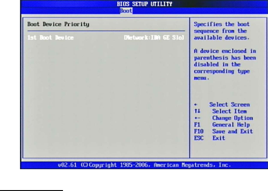
53
1st Boot Device
The items allow you to set the sequence of boot devices where BIOS attempts to
load
the disk operating system. First press <Enter> to enter the sub-menu. Then you
may
use the arrow keys (↑↓) to select the desired device, then press <+>, <-> or
<PageUp>, <PageDown> key to move it up/down in the priority list.
The choice: (Network:IBA GE Slot 0200 v1324), Disabled.
54
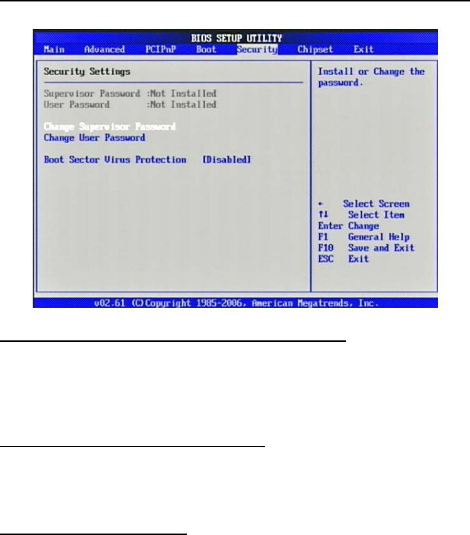
3.6 Security
Use this menu to set supervisor and user passwords.
Supervisor Password / Change Supervisor Password
Supervisor Password controls access to the BIOS Setup utility. These settings
allow
you to set or change the supervisor password.
User Password / Change User Password
User Password controls access to the system at boot. These settings allow you to
set or
change the user password.
Boot Sector Virus Protection
Boot Sector Virus Protection.
The choice: Disabled, Enabled.
55
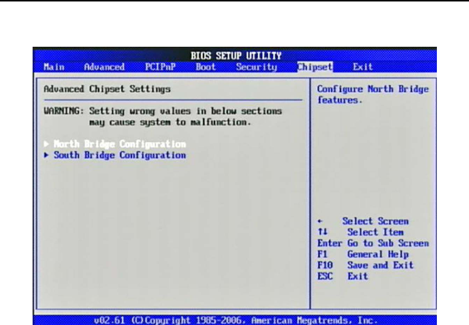
3.7 Chipset
This menu controls the advanced features of the onboard Northbridge and
Southbridge.
56
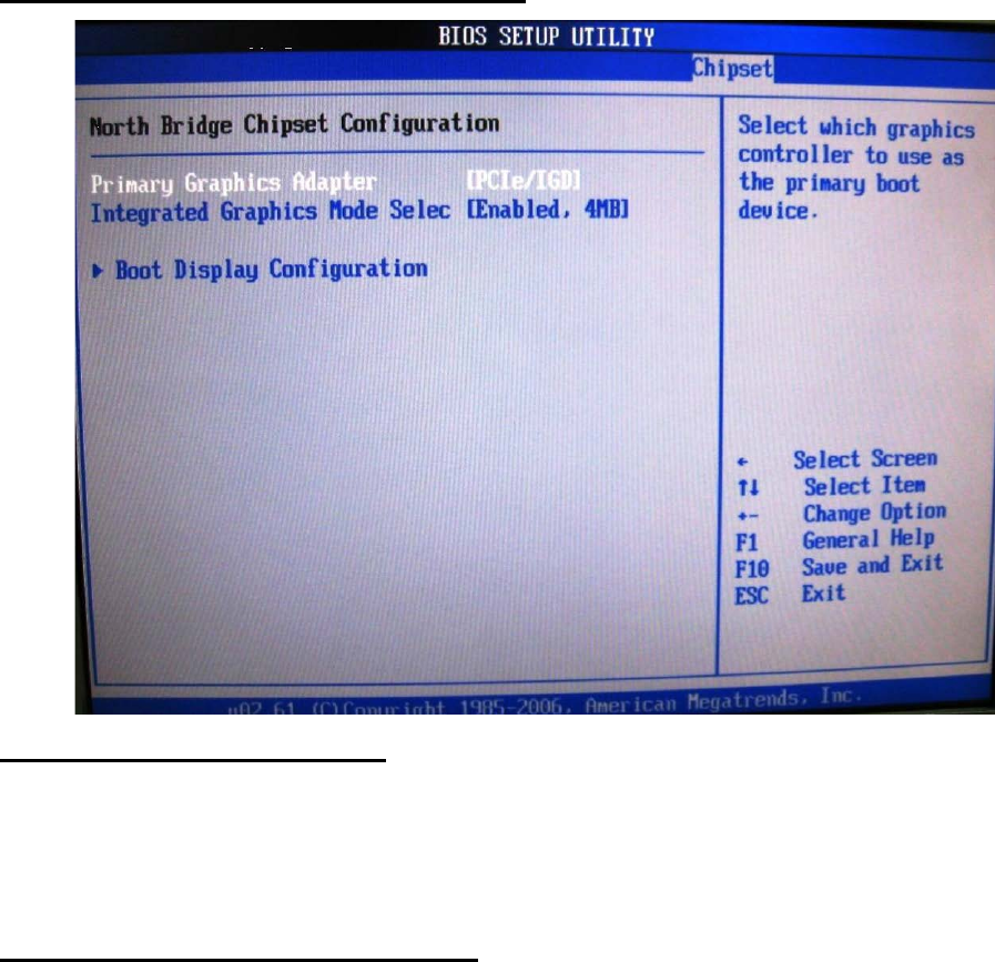
North Bridge Chipset Configuration
Primary Graphics Adapter
Select which graphics controller to use as the primary boot device.
The choice: IGD, PCIe/IGD.
Integrated Graphics Mode Selec
Select the amount of system memory used by the internal graphics device.
The choice: Disabled, Enabled, 1MB, Enabled, 4MB, Enabled, 8MB.
57
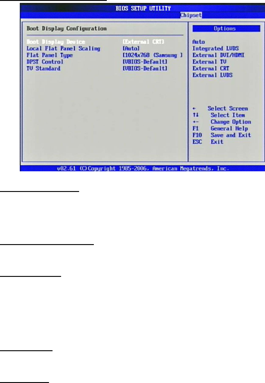
Boot Display Configuration
Boot Display Device
The choice: Auto, Integrated LVDS, External DVI/HDMI, External TV, External
CRT
External LVDS.
Local Flat Panel Scaling
The choice: Auto, Forced Scaling, Disabled.
Flat Panel Type
The choice: 640x480 (generic), 800x600 (generic), 1024x768 (generic),
640x480 (NEC
8.4”), 800x600 (NEC 9”), 1024x600 (TMD 5.61”), 1024x600 (Samsung
4.8”), 1024x768 (Samsung 15”), 1280x768 (Sharp 7.2”), 1280x800
(Samsung 15.4”), 1366x768 (TMD 11.1").
DPST Control
The choice: VBIOS-Default, DPST Disabled, DPST Enabled at Level 1~Level 5.
TV Standard
The choice: VBIOS-Default, NTSC, PAL, SECAM, SMPTE240M, ITU-R television,
58
SMPTE295M, SMPTE296M, CEA 7702, CEA 7703.
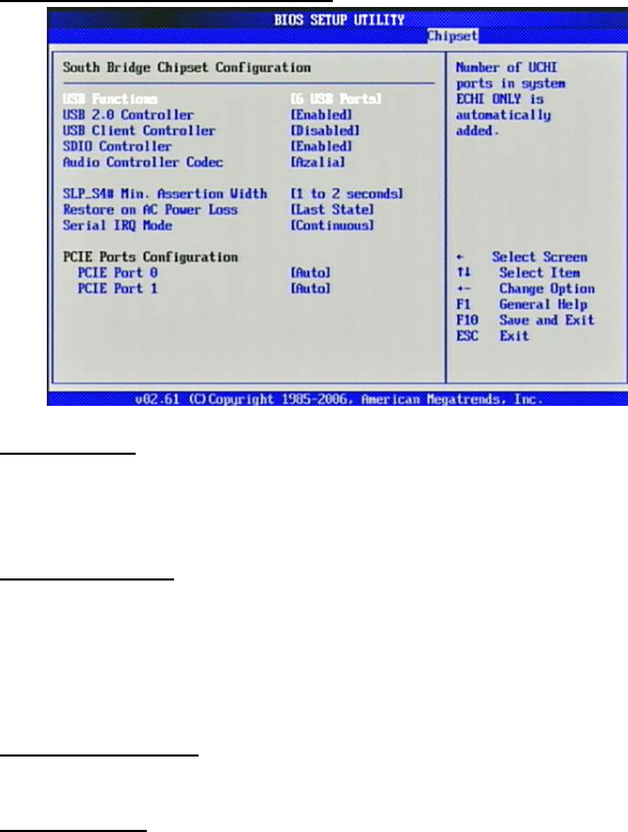
South Bridge Chipset Configuration
USB Functions
This setting specifies the function of the onboard USB controller.
The choice: Disabled, 2 USB Ports, 4 USB Ports, 6 USB Ports.
USB 2.0 Controller
Set to [Enabled] if you need to use any USB 2.0 device in the operating system
that
does not support or have any USB 2.0 driver installed, such as DOS.
The choice: Enabled, Disabled.
USB Client Controller
The choice: Enabled, Disabled.
SDIO controller
The choice: Enabled, Disabled.

59
Audio Controller Codec
The choice: Auto, Azalia, Disabled.
SLP_S4# Min. Assertion Width
The choice: 4 to 5 seconds, 3 to 4 seconds, 2 to 3 seconds, 1 to 2 seconds.
Restore on AC Power Loss
This item allows user to configure the power status of using ATX power supply
after
a serious power loss occurs.
The choice: Power Off, Power On, Last State.
Serial IRQ Mode
The choice: Continuous, Quiet.
PCIE Port 0
The choice: Auto, Enabled, Disabled.
PCIE Port 1
The choice: Auto, Enabled, Disabled.
60
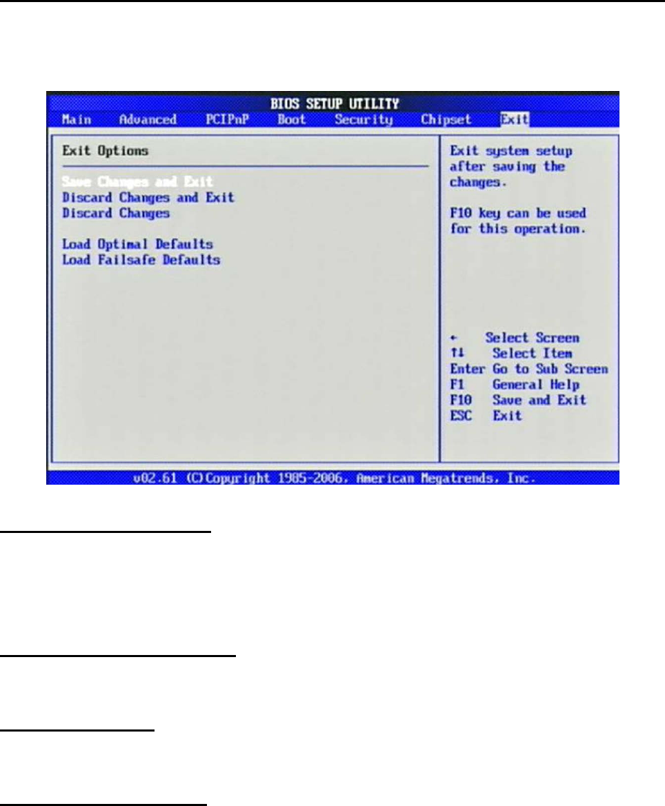
3.8 Exit
This menu allows you to load the BIOS default values or factory default settings
into
the BIOS and exit the BIOS setup utility with or without changes.
Save Changes and Exit
Exit System Setup and save your changes to CMOS. Pressing <Enter> on this
item
asks for confirmation: Save changes to CMOS and exit the Setup Utility.
Discard Changes and Exit
Abandon all changes and exit the Setup Utility.
Discard Changes
Abandon all changes and continue with the Setup Utility.
Load Optimal Defaults
Use this menu to load the default values set by the SBC manufacturer specifically
for
optimal performance of the SBC.

61
Load Failsafe Defaults
Use this menu to load the default values set by the BIOS vendor for stable system
performance.
62
Chapter 4 Appendix
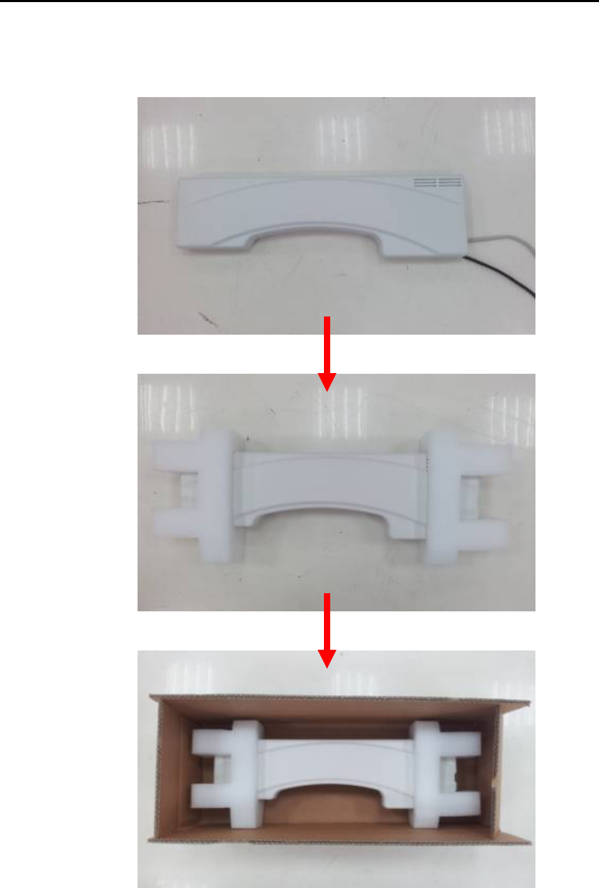
4.1 Protective Packing
Carefully packing your "WiSP" System (save the box and packing materials for
future use).
See the picture below for packing the "WiSP" System:

63
4.2 FCC Caution
This device complies with Part 15 of the FCC Rules. Operation is subject to
the following two conditions: (1) This device may not cause harmful interference,
and (2) this device must accept any interference received, including interference
that may cause undesired operation.
FCC Caution: Any changes or modifications not expressly approved by the
party responsible for compliance could void the user's authority to operate this
equipment.
This transmitter must not be co-located or operating in conjunction with any
other antenna or transmitter.
This equipment has been tested and found to comply with the limits for a
Class B digital device, pursuant to Part 15 of the FCC Rules. These limits are
designed to provide reasonable protection against harmful interference in a
residential installation. This equipment generates, uses and can radiate radio
frequency energy and, if not installed and used in accordance with the
instructions, may cause harmful interference to radio communications.
However, there is no guarantee that interference will not occur in a particular
installation. If this equipment does cause harmful interference to radio or
television reception, which can be determined by turning the equipment off and
on, the user is encouraged to try to correct the interference by one of the
following measures:
- Reorient or relocate the receiving antenna.
- Increase the separation between the equipment and receiver.
- Connect the equipment into an outlet on a circuit different from that
to which the receiver is connected.
- Consult the dealer or an experienced radio/TV technician for help.
Radiation Exposure
This equipment complies with FCC radiation exposure limits set forth for an
uncontrolled environment. This equipment should be installed and operated with
minimum distance 20cm between the radiator & your body.