Poulan PPFT55 User Manual To The 1906346d 5618 4c73 Ae82 71a6687d52a2
User Manual: Poulan PPFT55 to the manual
Open the PDF directly: View PDF ![]() .
.
Page Count: 24
OWNER'S MANUAL
MODEL:
PPFT55
FRONT TINE TILLER
ALWAYS WEAR EYE PROTECTION DURING OPERATION
Visit our website: www.poulan.pro.com
WARNING:
Read this Man u al and follow all Warnings and
Safety Instructions. Fail ure to do so can re sult
in serious in ju ry.
IMPORTANT MANUAL Do Not Throw Away
403661 Rev. 3 06.19.06 TR/VB
Printed in U.S.A.

2
• Keep children and pets away.
• Do not overload the machine capacity by attempting
to till too deep at too fast a rate.
• Never operate the machine at high speeds on slippery
surfaces. Look behind and use care when backing.
• Never allow bystanders near the unit.
• Use only attachments and accessories approved by
the manufacturer of the tiller.
• Never operate the tiller without good visibility or light.
• Be careful when tilling in hard ground. The tines may
catch in the ground and propel the tiller forward. If this
occurs, let go of the handlebars and do not restrain the
machine.
MAINTENANCE AND STORAGE
• Keep machine, attachments, and accessories in safe
work ing condition.
• Check shear pins, engine mounting bolts, and other
bolts at frequent intervals for proper tightness to be
sure the equip ment is in safe working condition.
• Never store the machine with fuel in the fuel tank inside
a building where ignition sources are present, such
as hot water and space heaters, clothes dryers, and
the like. Allow the engine to cool before storing in any
enclosure.
• Always refer to the operator’s guide instructions for
im por tant details if the tiller is to be stored for an ex-
tended period.
- IMPORTANT -
CAUTIONS, IMPORTANTS, AND NOTES ARE A MEANS OF
ATTRACTING ATTENTION TO IMPORTANT OR CRIT I CAL
IN FOR MA TION IN THIS MANUAL.
IMPORTANT: USED TO ALERT YOU THAT THERE IS A
POS SI BIL I TY OF DAM AG ING THIS EQUIP MENT.
NOTE: Gives essential information that will aid you to
better un der stand, incorporate, or execute a particular set
of instructions.
Look for this symbol to point out im-
por tant safety precautions. It means
CAUTION!!! BE COME ALERT!!! YOUR
SAFE TY IS INVOLVED.
CAUTION: Always disconnect spark
plug wire and place wire where it can-
not contact spark plug in order to pre-
vent ac ci den tal starting when setting
up, trans port ing, adjusting or making
re pairs.
SAFETY RULES
Safe Operation Practices for Walk-Behind Powered Ro ta ry Tillers
TRAINING
• Read the Owner’s Manual care ful ly. Be thor ough ly
fa mil iar with the controls and the proper use of the
equip ment. Know how to stop the unit and disengage
the controls quickly.
• Never allow children to operate the equipment. Never
allow adults to op er ate the equipment without proper
instruction.
• Keep the area of operation clear of all persons, par-
tic u lar ly small children, and pets.
PREPARATION
• Thoroughly inspect the area where the equipment is
to be used and remove all foreign objects.
• Disengage all clutches and shift into neutral before
starting the engine (mo tor).
• Do not operate the equipment with out wearing ad e -
quate outer gar ments. Wear footwear that will im prove
footing on slippery surfaces.
• Handle fuel with care; it is highly fl ammable.
• Use an approved fuel container.
• Never add fuel to a running engine or hot engine.
• Fill fuel tank outdoors with extreme care. Never fi ll fuel
tank indoors.
• Replace gasoline cap securely and clean up spilled
fuel before restarting.
• Use extension cords and receptacles as specifi ed by
the manufacturer for all units with electric drive motors
or electric starting motors.
• Never attempt to make any adjustments while the
engine (motor) is running (except where specifi cally
rec om mend ed by manufacturer).
OPERATION
• Do not put hands or feet near or under rotating parts.
• Exercise extreme caution when op er at ing on or cross-
ing gravel drives, walks, or roads. Stay alert for hidden
hazards or traffi c. Do not carry pas sen gers.
• After striking a foreign object, stop the engine (motor),
remove the wire from the spark plug, thoroughly in spect
the tiller for any damage, and repair the damage before
restarting and op er at ing the tiller.
• Exercise caution to avoid slipping or falling.
• If the unit should start to vibrate ab nor mal ly, stop the
engine (motor) and check immediately for the cause.
Vi bra tion is generally a warning of trouble.
• Stop the engine (motor) when leaving the operating
position.
• Take all possible precautions when leav ing the ma chine
unattended. Disengage the tines, shift into neutral, and
stop the engine.
• Before cleaning, repairing, or inspecting, shut off the
engine and make certain all moving parts have stopped.
Disconnect the spark plug wire, and keep the wire away
from the plug to prevent accidental starting. Disconnect
the cord on electric motors.
• Do not run the engine indoors; exhaust fumes are
dangerous.
• Never operate the tiller without proper guards, plates,
or other safety protective devices in place.
WARNING
The engine exhaust from this product con-
tains chem i cals known to the State of Cal i -
for nia to cause cancer, birth defects, or other
reproductive harm.

3
PRODUCT SPECIFICATIONS
Gasoline Capacity: 3 Quarts (2.8L)
Unleaded Regular
Oil (API-SG-SL): SAE 30 (Above 32°F/0°C)
(Capacity: 20 oz./0.6L) SAE 5w-30(Below 32°F/0°C)
Spark Plug: Champion RC12YC
(Gap: .030"/0.76mm)
CONGRATULATIONS on your purchase of a new tiller. It
has been designed, en gi neered and manu fac tured to give
you the best pos sible de penda bil ity and per form ance.
Should you experience any prob lems you can not easily
remedy, please contact your nearest authorized service
center. We have com pe tent, well-trained tech ni cians and
the proper tools to service or repair this unit.
Please read and retain this manual. The in struc tions will
enable you to assemble and main tain your tiller prop erly.
Always observe the “SAFETY RULES”.
IMPORTANT: THIS UNIT IS EQUIPPED WITH AN INTERNAL
COMBUSTION ENGINE AND SHOULD NOT BE USED ON
OR NEAR ANY UNIMPROVED FOREST-COVERED, BRUSH-
COVERED OR GRASS COVERED LAND UNLESS THE
ENGINE'S EXHAUST SYSTEM IS EQUIPPED WITH A SPARK
ARRESTER MEETING APPLICABLE LOCAL LAWS (IF ANY).
IF A SPARK ARRESTER IS USED, IT SHOULD BE MAINTAINED
IN EFFECTIVE WORK ING ORDER BY THE OPERATOR.
IN THE STATE OF CALIFORNIA, A SPARK ARRESTER IS
REQUIRED BY LAW (SECTION 4442 OF THE CALIFORNIA
PUBLIC RESOURCES CODE). OTHER STATES MAY HAVE
SIMILAR LAWS. FEDERAL LAWS APPLY ON FEDERAL LANDS.
SEE YOUR AUTHORIZED SERVICE CENTER/DEPARTMENT
FOR SPARK ARRESTER.
CUSTOMER RESPONSIBILITIES
• Read and observe the safety rules.
• Follow a regular schedule in maintaining, caring for
and using your tiller.
• Follow instructions under “Maintenance” and “Stor age”
sections of this Manual.
MAINTENANCE ..................................................... 10-12
SERVICE & ADJUSTMENTS ................................. 12-14
STORAGE .................................................................... 15
TROUBLESHOOTING ................................................. 16
REPAIR PARTS........................................................... 17-
WARRANTY................................................................. 17
SAFETY RULES ............................................................ 2
PRODUCT SPECIFICATIONS ....................................... 3
CUSTOMER RESPONSIBILITIES................................. 3
ASSEMBLY ................................................................. 4-5
OPERATION ............................................................... 6-9
MAINTENANCE SCHEDULE ...................................... 10
TABLE OF CONTENTS
4
ASSEMBLY
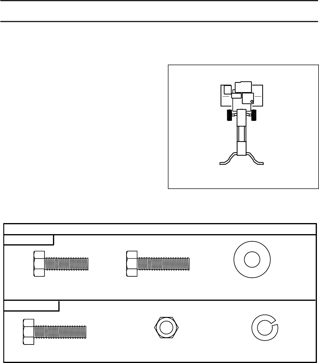
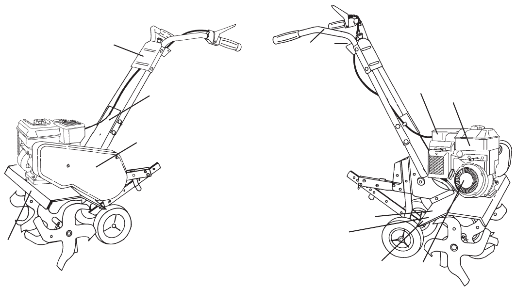
OPERATOR’S POSITION (See Fig. 1)
When right or left hand is mentioned in this manual, it
means when you are in the operating position (standing
behind tiller handles).
Your new tiller has been assembled at the factory with exception of those parts left unassembled for shipping purposes.
To ensure safe and proper operation of your tiller all parts and hardware you assemble must be tightened securely. Use
the correct tools as necessary to insure proper tightness.
TOOLS REQUIRED FOR ASSEMBLY
A socket wrench set will make assembly easier. Standard
wrench sizes are listed.
(1) Utility knife
(1) Screwdriver
(2) 1/2" wrenches
OPERATOR'S POSITION
RIGHT
FRONT
LEFT
overhead_views_8
FIG. 1
(6) Lock Washers 5/16
(6) Hex Nuts 5/16-18
(2) Hex Bolts 5/16-18 x 1-1/4
(2) Hex Bolts 5/16-18 x 1-1/4
(2) Hex Bolts 5/16-18 x 1 (4) Washers
3/8 x 7/8 x 14 Ga.
CONTENTS OF HARDWARE PACK
HANDLE
DEPTH STAKE
5
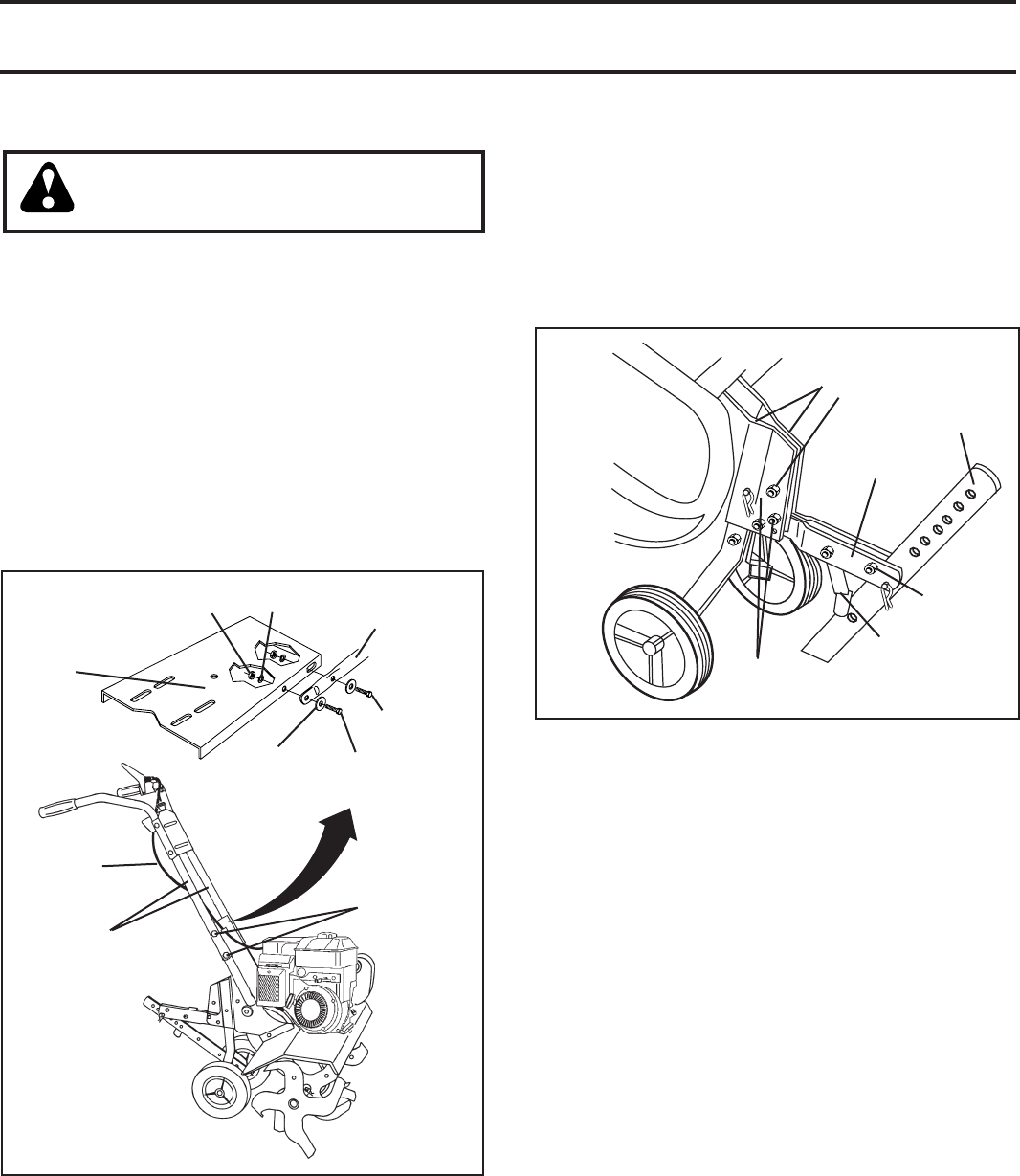
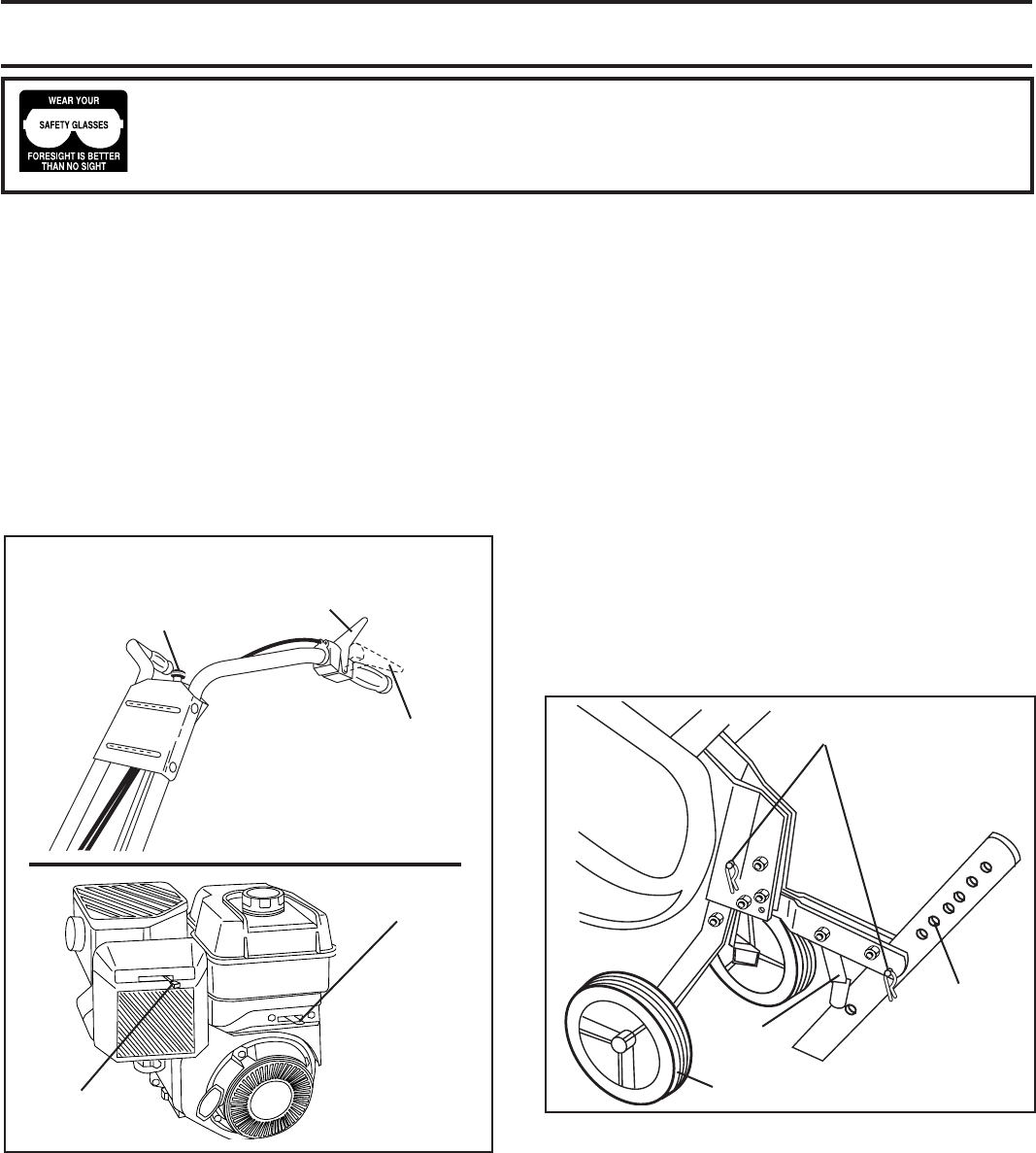
UNPACK CARTON & INSTALL HANDLE
(See Fig. 2)
CAUTION: Be careful of exposed
sta ples when handling or disposing
of cartoning material.
IMPORTANT: WHEN UNPACKING AND AS SEM BLING
TILLER, BE CAREFUL NOT TO STRETCH OR KINK
CABLE(S).
• Cut cable ties securing handles.
• Slowly lift handle as sem bly up, route cable(s) as shown
and align han dle holes with handle panel hole and
slot.
• Loosely assemble hardware as shown. Be sure the
shorter (1" long) hex bolt is assembled in lower hole
of handle. Repeat for opposite side. Tight en all hard-
ware se cure ly.
• Cut cable ties securing tiller to skid and remove tiller
from skid.
• Remove screws securing depth stake to skid and dis-
card the screws.
depth_stake_4
DEPTH
STAKE
SUPPORT
BOLT
5/16 X 1-1/4 HEX BOLTS,
LOCK WASH ERS,
AND HEX NUTS
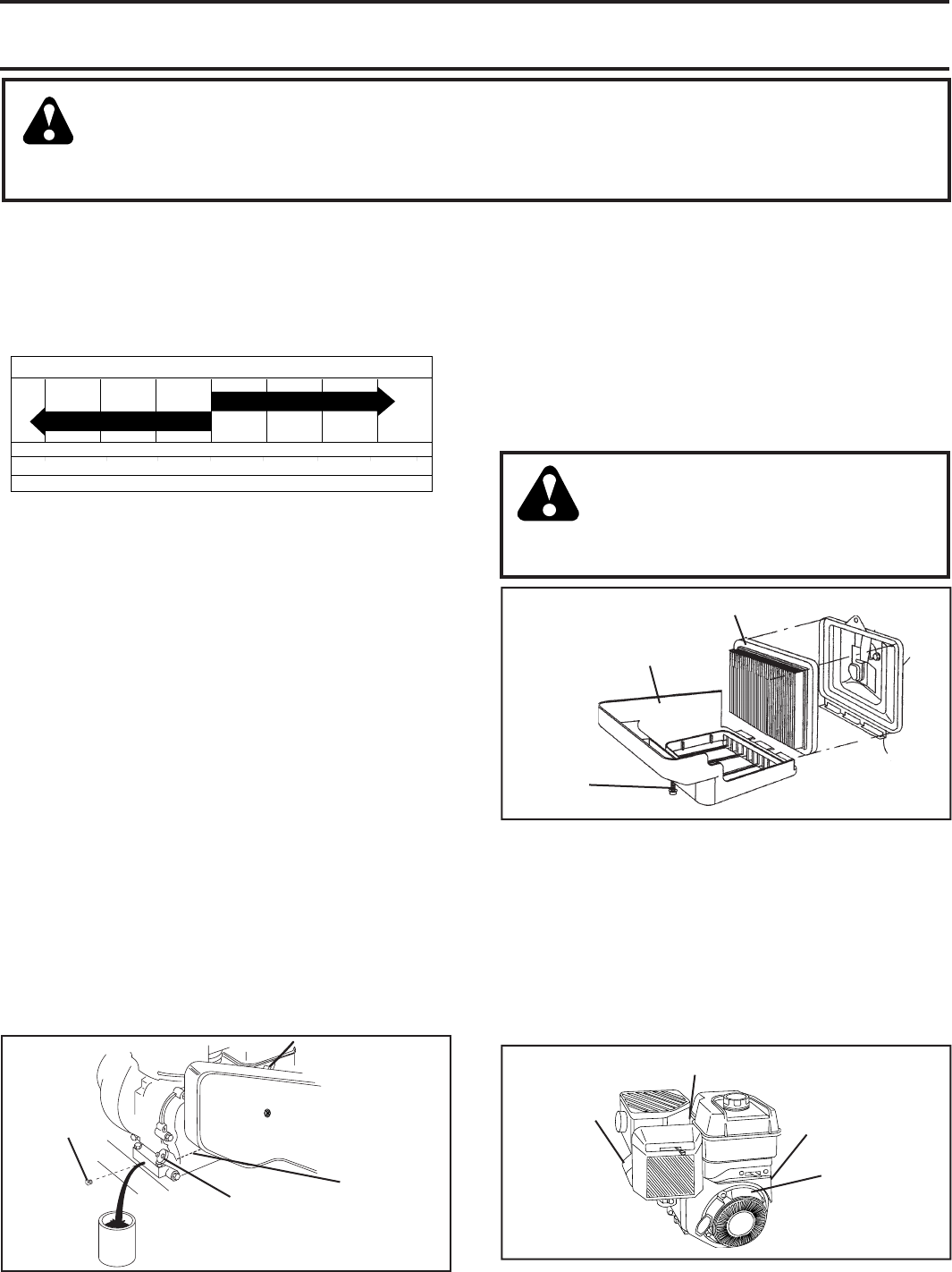
DEPTH STAKE
SUPPORT
NUT “A”
ENGINE BRACK ET
HALVES
FIG. 3
STAKE
SPRING
TILLER
HANDLES
02051
CABLE(S)
FIG. 2
handles_38
HANDLE
PANEL
BOLTS
FLAT
WASHER HEX BOLT
5/16-18X1"
TILLER
HANDLE
HAN DLE
PANEL
NUT
LOCK
WASH ER
HEX BOLT
5/16-18X1-1/4"
ASSEMBLY
HANDLE HEIGHT
• Handle height may be adjusted to better suit operator.
(See “HANDLE HEIGHT” in the Service and Ad just -
ments section of this manual).
TILLING WIDTH
• Tilling width may be adjusted to better handle your
tilling con di tions (See “TINE ARRANGEMENT” in the
Service and Adjustments section of this manual).
TINE OPERATION
• Check tine operation before fi rst use. (See “TINE OP-
ERATION CHECK” in the Service and Adjustments
section of this manual).
INSTALL DEPTH STAKE AS SEM BLY
(See Fig. 3)
• Loosen nut “A”.
• Insert stake support between engine brack et halves
with stake spring down.
• Bolt stake support to engine brackets with 5/16 x 1-1/4"
bolts, lock washers and nuts. Tight en se curely. Tighten
nut “A”.
• Depth stake must move freely. If it does not, loosen
support bolt.
6
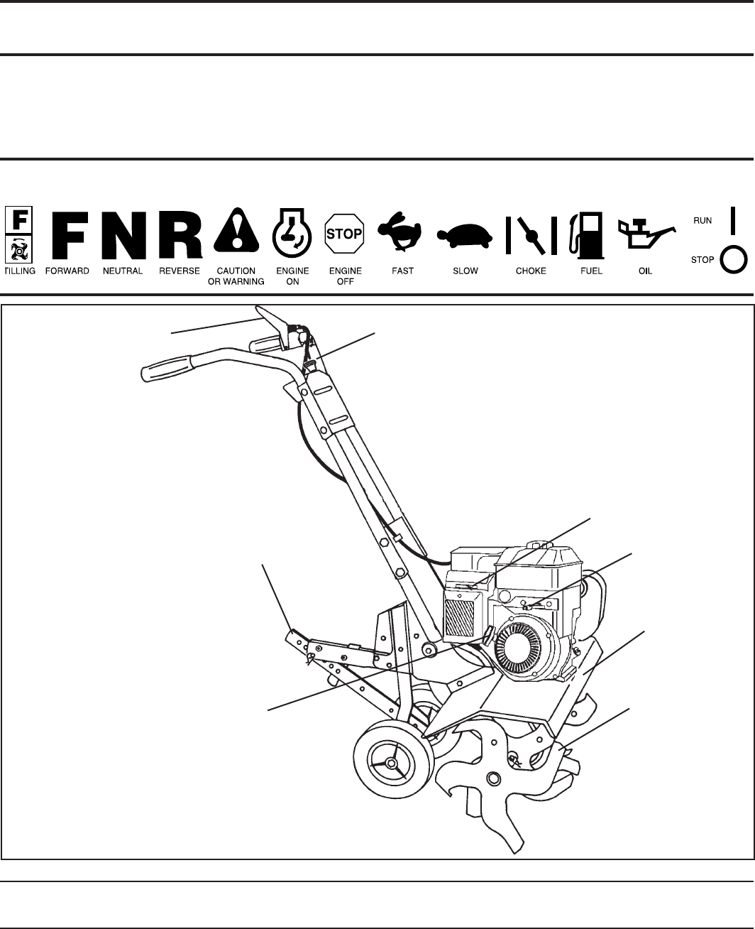
KNOW YOUR TILLER
READ THIS MANUAL AND SAFETY RULES BEFORE OPERATING YOUR TILLER.
Compare the illustrations with your tiller to familiarize yourself with the location of various controls and adjustments. Save
this manual for future reference.
REVERSE TINE
CONTROL
These symbols may appear on your Tiller or in literature supplied with the product. Learn and understand their mean-
ing.
RECOIL
STARTER
HANDLE
DEPTH STAKE
TINE
SHIELD
CHOKE CONTROL
FORWARD TINE
CONTROL
TINES
THROTTLE
CONTROL
FIG. 4
MEETS ANSI SAFETY REQUIREMENTS
Our tillers conform to the safety standards of the American National Standards Institute.
CHOKE CONTROL - Used when starting a cold engine.
DEPTH STAKE - Controls forward speed and the depth at
which the tiller will dig.
FORWARD TINE CONTROL - Engages tines in forward
direction.
OPERATION
REVERSE TINE CONTROL - Engages tines in reverse
RECOIL STARTER HANDLE - Used to start the engine.
direction.
THROTTLE CONTROL - Controls engine speed.
7
handles_94
FORWARD TINE CON TROL IN
“OFF ” (UP) POSITION
REVERSE
CONTROL
engine_art_
71
CHOKE
CONTROL
THROTTLE
CONTROL
FORWARD TINE CON TROL
IN “ON” (DOWN) POSITION
TINE OPERATION (See Fig. 5)
FORWARD
• Squeeze forward tine control to handle.
REVERSE
• With forward tine control “OFF” (up) position, pull back
and hold reverse tine control.
FIG. 5
HOW TO USE YOUR TILLER
Know how to operate all controls before adding fuel and oil
or attempting to start engine.
The operation of any tiller can result in foreign objects thrown into the eyes, which can result
in severe eye damage. Always wear safety glasses or eye shields before starting your tiller
and while tilling. We recommend a wide vision safety mask for over spectacles or standard
safety glasses.
STOPPING (See Fig. 5)
TINES
• Release forward tine control to stop forward move-
ment.
• Release reverse tine control to stop reverse move-
ment.
ENGINE
• Move throttle control to “STOP” position.
• Never use choke to stop engine.
TILLING
The speed and depth of tilling is regulated by the position
of the depth stake and wheel height.
The depth stake should always be below the wheels for
digging. It serves as a brake to slow the tiller’s forward
motion to enable the tines to penetrate the ground. Also,
the more the depth stake is lowered into the ground the
deeper the tines will dig.
DEPTH STAKE (See Fig. 6)
Adjust depth stake by removing the hairpin clip and clevis
pin. Change depth stake to desired position. Replace the
clevis pin and hairpin clip.
• For normal tilling, set depth stake at the second or third
hole from the top.
WHEELS (See Fig. 6)
Adjust wheels by removing the hairpin clip and clevis pin.
Change wheel position. Replace the hairpin clip and clevis
pin.
• For normal tilling, set wheels at the second or third
hole from the top.
depth_stake_4
DEPTH
STAKE
STAKE
SPRING
HAIRPIN CLIP
AND CLEVIS PIN
WHEEL
FIG. 6
OPERATION
8
TO TRANSPORT
CAUTION: Before lifting or trans port ing,
allow tiller engine and muffl er to cool.
Disconnect spark plug wire. Drain
gasoline from fuel tank.
AROUND THE YARD
• Tip depth stake forward until it is held by the stake
spring.
• Push tiller handles down, raising tines off the ground.
• Push or pull tiller to desired location.
AROUND TOWN
• Disconnect spark plug wire.
• Drain fuel tank.
• Transport in upright position to prevent oil leakage.
FIG. 7
engine_art_4
OIL
FILLER
PLUG
OIL
LEVEL
BEFORE STARTING ENGINE
IMPORTANT: BE VERY CAREFUL NOT TO ALLOW DIRT
TO ENTER THE ENGINE WHEN CHECKING OR ADDING
OIL OR FUEL. USE CLEAN OIL AND FUEL AND STORE IN
AP PROVED, CLEAN, COVERED CONTAINERS. USE CLEAN
FILL FUNNELS.
FILL ENGINE WITH OIL (See Fig. 7)
• With engine level, remove engine oil fi ller plug.
• Fill engine with oil to point of overfl owing. For ap prox-
i mate ca pac i ty see “PRODUCT SPEC I FI CA TIONS” on
page 3 of this manual.
• Tilt tiller back on its wheels and then re-level.
• With engine level, refi ll to point of overfl owing if nec-
es sary. Re place oil fi ller plug.
• For cold weather operation you should change oil for
easier starting (See “OIL VISCOSITY CHART” in the
Maintenance section of this manual).
• To change engine oil, see the Maintenance section of
this manual.
OPERATION
TO START ENGINE (See Fig. 8)
CAUTION: Keep drive control bar in
“DISENGAGED” position when start-
ing en gine.
When starting engine for the fi rst time or if engine has run
out of fuel, it will take extra pulls of the recoil starter to
move fuel from the tank to the engine.
• Make sure spark plug wire is prop er ly connected.
• Move shift lever indicator to “N” (neutral) position.
• Place throttle control in “FAST” position.
• Turn fuel shut-off valve 1/4 turn to open position.
• Move choke control to choke position.
• Grasp recoil starter handle with one hand and grasp
tiller handle with other hand. Pull rope out slowly until
engine reaches start of com pres sion cycle (rope will
pull slightly harder at this point).
• Pull recoil starter handle quickly. Do not let starter
handle snap back against starter.
• If engine fi res but does not start, move choke control
to half choke position. Pull recoil starter handle until
engine starts.
• When engine starts, slowly move choke control to
"RUN" position as engine warms up.
NOTE: A warm engine requires less choking to start.
• Move throttle control to desired running position.
• Allow engine to warm up for a few minutes before
engaging tines.
ADD GASOLINE
• Fill fuel tank to bottom of fi ller neck. Do not overfi ll.
Use fresh, clean, regular un lead ed gasoline with a
minimum of 87 octane. (Use of leaded gasoline will
increase carbon and lead oxide deposits and reduce
valve life). Do not mix oil with gasoline. Purchase fuel
in quan ti ties that can be used within 30 days to assure
fuel freshness.
CAUTION: Fill to within 1/2 inch of top
of fuel tank to prevent spills and to allow
for fuel expansion. If gasoline is ac-
ci den tal ly spilled, move machine away
from area of spill. Avoid creating any
source of ignition until gasoline vapors
have disappeared.
Wipe off any spilled oil or fuel. Do not
store, spill or use gasoline near an
open fl ame.
IMPORTANT: WHEN OPERATING IN TEMPERATURES
BELOW32°F(0°C), USE FRESH, CLEAN WINTER GRADE
GAS O LINE TO HELP INSURE GOOD COLD WEATHER
START ING.
CAUTION: Alcohol blended fuels (called
gas o hol or using ethanol or methanol) can at-
tract moisture which leads to sep a ra tion and
for ma tion of acids during storage. Acidic gas
can damage the fuel system of an engine while
in storage. To avoid engine problems, the fuel
system should be emptied before stor age of
30 days or longer. Drain the gas tank, start
the engine and let it run until the fuel lines
and carburetor are empty. Use fresh fuel next
sea son. See Storage In struc tions for additional
information. Never use engine or carburetor
cleaner products in the fuel tank or permanent
damage may occur.
9
engine_art_
71
BREAKING IN YOUR TILLER
Break-in your belt(s), pulleys and tine control before you
actually begin tilling.
• Start engine, tip tines off ground by pressing handles
down and engage tine control to start tine rotation.
Allow tines to rotate for fi ve minutes.
• Check tine operation and adjust if necessary. See “TINE
OPERATION CHECK” in the Service and Ad just ments
sec tion of this manual.
TILLING HINTS
CAUTION: Until you are accustomed
to handling your tiller, start ac tu al fi eld
use with throttle in slow position.
To help tiller move forward, lift up the handles slightly (thus
lifting depth stake out of ground). To slow down the tiller,
press down on handles.
If you are straining or tiller is shaking, the wheels and depth
stake are not set properly in the soil being tilled. The proper
setting of the wheels and depth stake is through trial and
error and depends upon the soil con di tion. (The harder or
wetter the ground, the slower the engine and tine speed
needed. Under these poor con di tions, at fast speed the
tiller will run and jump over the ground).
A properly adjusted tiller will dig with little effort from the
operator.
• Tilling is digging into, turning over, and breaking up
packed soil before planting. Loose, unpacked soil helps
root growth. Best tilling depth is 4"-6". A tiller will also
clear the soil of unwanted vege ta tion. The de com po si tion
of this vegetable mat ter en rich es the soil. De pend ing
on the climate (rain fall and wind), it may be advisable
to till the soil at the end of the growing season to further
condition the soil.
• Soil conditions are important for proper tilling. Tines will
not readily penetrate dry, hard soil which may con trib ute
to excessive bounce and diffi cult handling of your tiller.
Hard soil should be mois tened before tilling; however,
extremely wet soil will “ball-up” or clump during tilling.
Wait until the soil is less wet in order to achieve the
best results. When tilling in the fall, remove vines and
long grass to prevent them from wrapping around the
tine shaft and slowing your tilling operation.
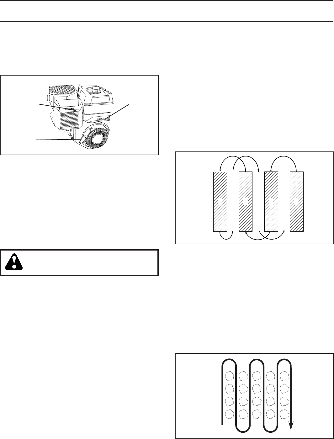
• You will fi nd tilling much easier if you leave a row un-
tilled between passes. Then go back between tilled
rows. (See Fig. 9) There are two reasons for doing
this. First, wide turns are much easier to negotiate than
about-faces. Sec ond, the tiller won’t be pulling itself,
and you, toward the row next to it.
• Set depth stake and wheel height for shallow tilling
when working extremely hard soil or sod. Then work
across the fi rst cuts at normal depth.
321
5
4
67
FIG. 9
CULTIVATING
Cultivating is destroying the weeds between rows to pre-
vent them from robbing nourishment and moisture from the
plants. At the same time, breaking up the upper layer of
soil crust will help retain moisture in the soil. Best digging
depth is 1"-3".
• You will probably not need to use the depth stake. Begin
by tipping the depth stake forward until it is held by the
stake spring.
• Cultivate up and down the rows at a speed which will
allow tines to uproot weeds and leave the ground in
rough con di tion, promoting no fur ther growth of weeds
and grass (See Fig. 10).
FIG. 10
OPERATION
FIG. 8
RECOIL STARTER
HANDLE
SPARK PLUG
CHOKE
CONTROL
THROTTLE
CONTROL
NOTE: If at a high altitude (3000 feet) or in cold
temperatures (below 32°F), the carburetor fuel mixture
may need to be adjusted for best engine performance.
See "TO ADJUST CARBURETOR" in the Service and
Adjustments section of this manual.
NOTE: If engine does not start, see troubleshooting
points.
10
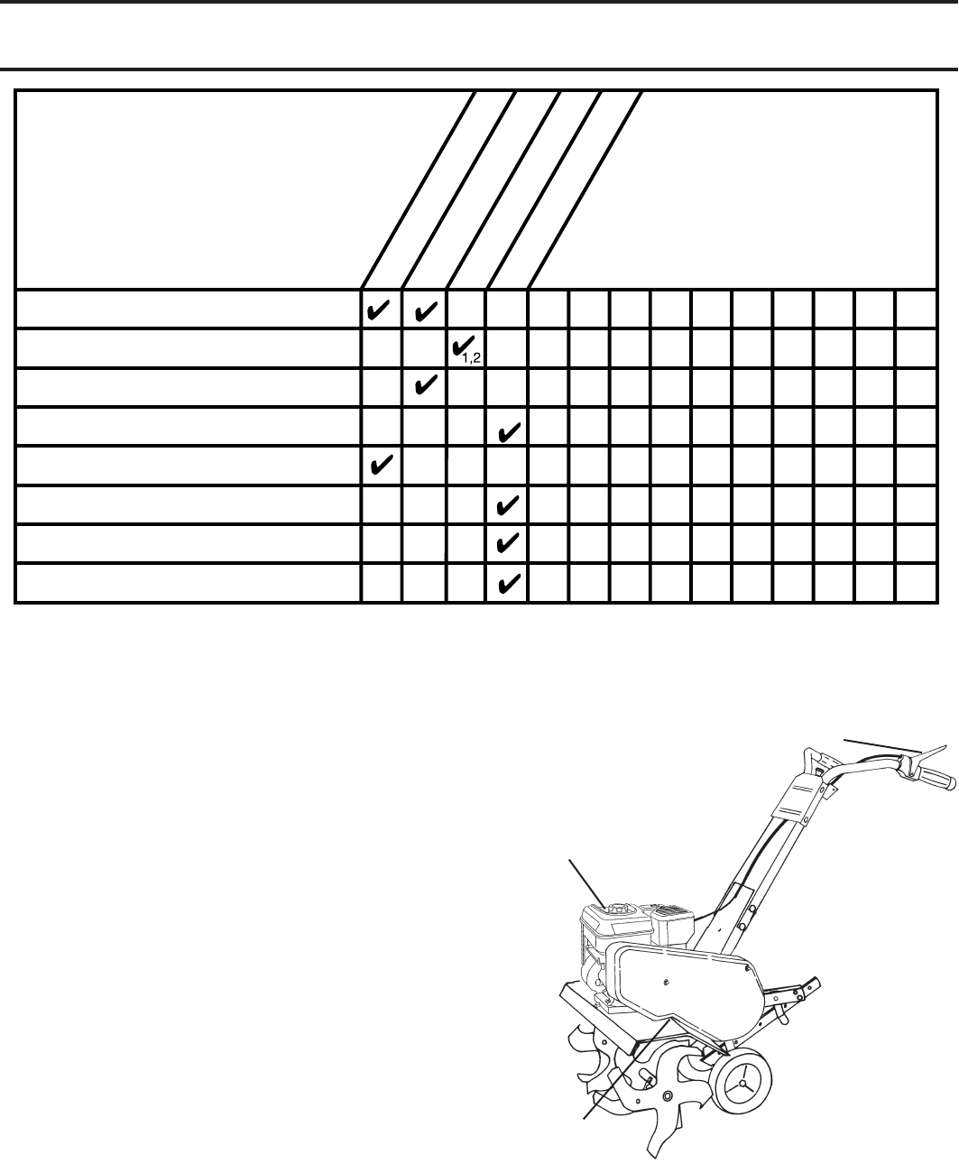
MAINTENANCE
SCHEDULE
FILL IN DATES
AS YOU COMPLETE
REGULAR SERVICE
Check Engine Oil Level
Change Engine Oil
Oil Pivot Points
Inspect Air Screen
Inspect Spark Arrester / Muffler
Clean or Replace Air Cleaner Cartridge
Clean Engine Cylinder Fins
Replace Spark Plug
BEFORE EACH USE
EVERY 25 HOURS
EVERY 5 HOURS
EVERY 50 HOURS
SERVICE DATES
2
1 - Change more often when operating under a heavy load or in high ambient temperatures.
2 - Service more often when operating in dirty or dusty conditions.
MAINTENANCE
cSAE 30 OR 10W-30 MOTOR OIL
dREFER TO MAINTENANCE “ENGINE” SECTION
LUBRICATION CHART
d EN GINE
c TINE CON TROL
c IDLER
ARM
GENERAL RECOMMENDATIONS
The warranty on this tiller does not cover items that have
been subjected to operator abuse or negligence. To receive
full value from the warranty, the operator must main tain tiller
as instructed in this manual.
Some adjustments will need to be made periodically to
properly maintain your tiller.
At least once a season, check to see if you should make
any of the adjustments described in the Service and Ad-
justments section of this manual.
• Once a year you should replace the spark plug, clean
or replace air fi lter, and check tines and belts for wear.
A new spark plug and clean air fi lter assure proper
air-fuel mixture and help your engine run better and
last longer.
BEFORE EACH USE
• Check engine oil level.
• Check tine operation.
• Check for loose fasteners.
LUBRICATION
Keep unit well lubricated (See “LUBRICATION CHART”).
11
FIG. 11
engine_art_12
FIG. 12
OIL
DRAIN
PLUG
OIL FILLER
PLUG
OIL LEVEL
TEMPERATURE RANGE ANTICIPATED BEFORE NEXT OIL CHANGE
SAE VISCOSITY GRADES
-20 0 30 40 80 100
-30 -20 0 20 30 40
F
C
32
-10 10
60
5W-30
SAE 30
oil_visc_chart1_e
MAINTENANCE
AIR
CLEANER
SCREW
COV ER
AIR CLEAN ER CAR TRIDGE
FIG. 13
Disconnect spark plug wire before performing any maintenance (except car bu re tor adjustment) to
prevent accidental start ing of engine.
Prevent fi res! Keep the engine free of grass, leaves, spilled oil, or fuel. Re move fuel from tank
before tipping unit for maintenance. Clean muffl er area of all grass, dirt, and debris.
Do not touch hot muffl er or cylinder fi ns as contact may cause burns.
ENGINE
LUBRICATION
Use only high quality detergent oil rated with API service
classifi cation SG-SL. Select the oil’s SAE vis cos i ty grade
according to your expected temperature.
NOTE: Although multi-viscosity oils (5W-30, 10W-30, etc.)
improve starting in cold weather, these multi viscosity oils
will result in increased oil consumption when used above
32°F (0°C). Check your engine oil level more frequently to
avoid possible engine damage from running low on oil.
Change the oil after every 25 hours of operation or at least
once a year if the tiller is not used for 25 hours in one year.
Check the crankcase oil level before starting the engine
and after each fi ve (5) hours of continuous use. Add SAE
30 motor oil or equivalent. Tighten oil fi ller plug securely
each time you check the oil level.
TO CHANGE ENGINE OIL (See Figs. 11 and 12)
Determine temperature range expected before oil change.
All oil must meet API service classifi cation SG-SL.
• Be sure tiller is on level surface.
• Oil will drain more freely when warm.
• Catch oil in a suitable container.
• Remove drain plug.
• Tip tiller forward to drain oil.
• After oil has drained completely, replace oil drain plug
and tighten securely.
• Remove oil fi ller plug. Be careful not to allow dirt to
enter the engine.
• Refi ll engine with oil. See “CHECK ENGINE OIL LEVEL”
in the Operation section of this manual.
AIR CLEANER (See Fig. 13)
Service air cleaner cartridge every twenty-fi ve hours, more
often if engine is used in very dusty conditions.
• Loosen air cleaner screws, one on each side of
cover.
• Remove air cleaner cover.
• Carefully remove air cleaner cartridge. Be care ful. Do
not allow dirt or de bris to fall into carburetor.
• Clean by tapping gently on a fl at surface.
• If very dirty or damaged, replace cartridge.
• Clean and re place cover. Tighten screws securely.
CAUTION: Petroleum sol vents, such as
kerosene, are not to be used to clean
cartridge. They may cause de te ri o ra tion
of the cartridge. Do not oil car tridge.
Do not use pres sur ized air to clean or
dry cartridge.
engine_art_71
BLOWER
HOUSING
AIR
SCREEN
CYLINDER FINS
MUF FLER
FIG. 14
COOLING SYSTEM (See Fig. 14)
Your engine is air cooled. For proper engine performance
and long life keep your engine clean.
• Clean air screen frequently using a stiff-bristled-
brush.
• Remove blower housing and clean as nec es sary.
• Keep cylinder fi ns free of dirt and chaff.
12
TILLER
TO ADJUST HANDLE HEIGHT (See Fig. 15)
Factory assembly has provided lowest handle height. Se lect
handle height best suited for your tilling conditions. Handle
height will be different when tiller digs into soil.
• If a higher handle height is desired, loosen the four
nuts securing handle panel to engine brackets.
• Slide handle panel to desired location.
• Tighten the four nuts securely.
HANDLE
PANEL
ENGINE BRACKETS
NUTS (ALSO 2
ON LEFT SIDE
OF TILLER)
FIG. 15
SERVICE AND ADJUSTMENTS
CAUTION: Disconnect spark plug wire from spark plug and place wire where it cannot come into
contact with plug.
FIG. 16
FIG. 17
MAINTENANCE
MUFFLER
Do not operate tiller without muffl er. Do not tamper with
exhaust system. Damaged muffl ers or spark arresters could
create a fi re hazard. Inspect pe ri odi cally and re place if
nec es sary. If your engine is equipped with a spark arrester
screen assembly, re move every 50 hours for cleaning and
inspection. Re place if dam aged.
SPARK PLUG
Replace spark plugs at the beginning of each tilling sea-
son or after every 50 hours of use, whichever comes fi rst.
Spark plug type and gap setting are shown in “PROD UCT
SPEC I FI CA TIONS” on page 3 of this manual.
TRANSMISSION
Your transmission is sealed and will not require lubrication
unless serviced.
CLEANING
Do not clean your tiller when the engine and transmission
are hot. We do not rec om mend using pressurized water
(gar den hose, etc.) to clean your unit un less the gasket
area around the trans mis sion and the engine muf fl er, air
fi l ter and car bu re tor are cov ered to keep wa ter out. Wa ter
in en gine will short en the useful life of your tiller.
• Clean engine, wheels, fi nish, etc. of all foreign mat-
ter.
• Keep fi nished surfaces and wheels free of all gas o line,
oil, etc.
• Protect painted surfaces with au to mo tive type wax.
TINE ARRANGEMENT
Your outer tines can be assembled in several different ways
to suit your tilling or cultivating needs.
CAUTION: Tines are sharp. Wear
gloves or other protection when han-
dling tines.
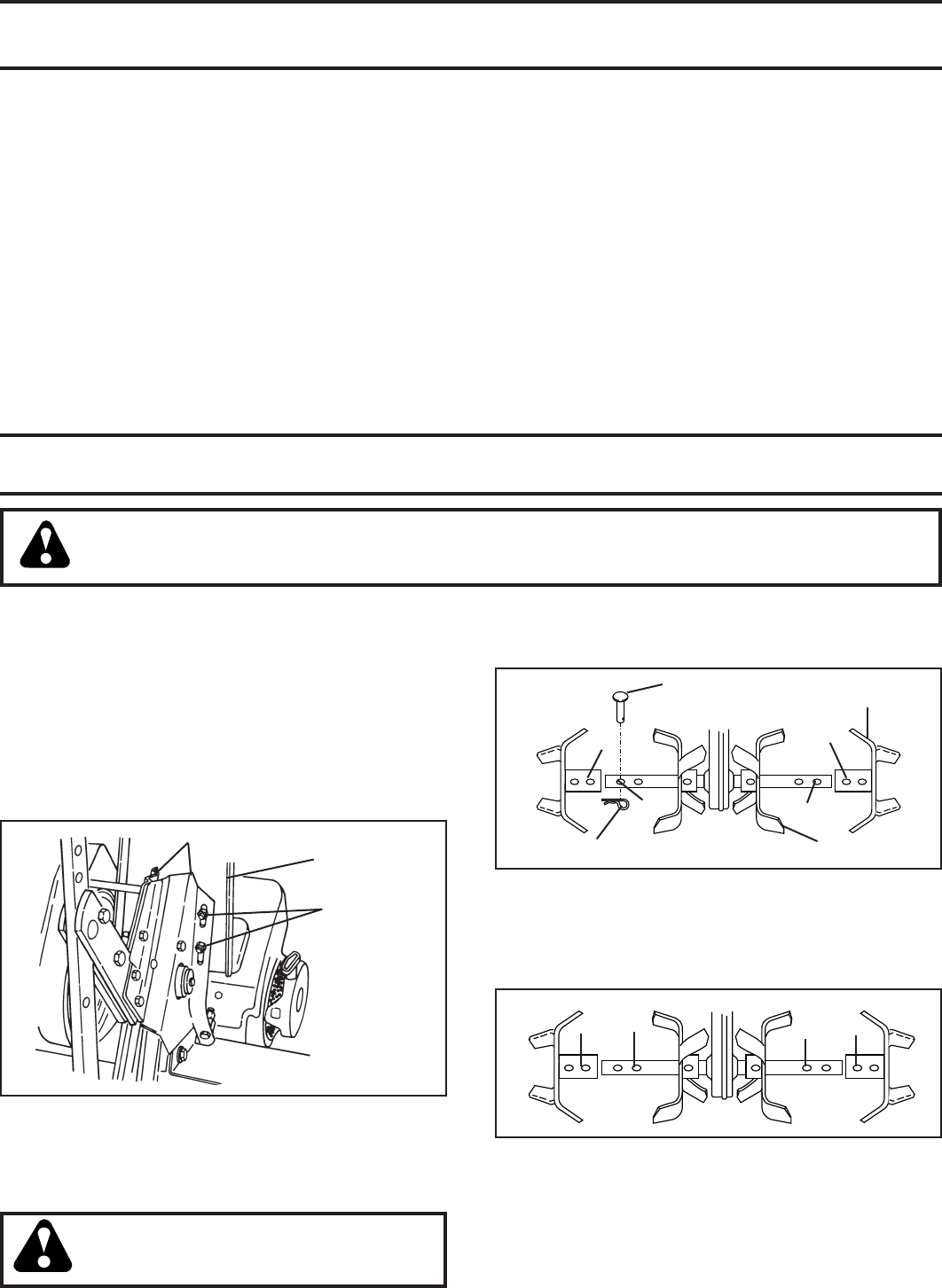
tine_4
OUTER
TINE
INNER TINE
HAIRPIN CLIP
A
B
A
B
CLEVIS
PIN
MID-WIDTH TILLING - 24" PATH (See Fig. 17)
• Assemble holes “A” in tine hubs to holes “C” in tine
shaft.
tine_5
A
C
AC
NORMAL TILLING - 26" PATH (See Fig. 16)
• Assemble holes “A” in tine hubs to holes “B” in tine
shaft.
13
FIG. 18
NARROW TILLING/CULTIVATING - 12-3/4" PATH
(See Fig. 18)
• Remove outer tines.
tine_
6
INNER TINES ONLY
NOTE: When reassembling outer tines, be sure right tine
assembly (marked “R”) and left tine assembly (marked “L”)
are mounted to correct side of tine shaft.
SERVICE AND ADJUSTMENTS
TINE OPERATION CHECK (See Fig. 19)
WARNING: Disconnect spark plug wire
from spark plug to prevent starting while
checking tine operation.
For proper tine operation, forward tine control lever must be
against control body and all slack removed from inner wire of
control cable when control is in the “OFF” (up) position.
If lever and cable are loose, loosen cable clip at lower end of
cable. Pull up on cable to remove slack, without extending
spring on end of cable, and retighten cable clip.
FINAL CHECK “OFF” POSITION
• With tine control “OFF” (up), push down on handle to
raise tines off the ground.
• Slowly pull recoil starter handle while observing tines.
Tines should not rotate.
• If tines rotate, inner wire of control cable is too tight
which is extending lower spring and engaging tines.
Loosen cable clip and push down on cable only enough
to relieve spring tension. Tighten cable clip.
• Recheck in “OFF” position and adjust if necessary.
FINAL CHECK “ON” POSITION
• With tine control “ON” (held down to handle) push down
on handle to raise tines off the ground.
• Slowly pull recoil starter handle while observing tines.
Tines should rotate forward.
• If tines do not rotate, inner wire of control cable is too
loose. Loosen cable clip and pull cable up to remove
slack and retighten clip.
• Recheck in “ON” position and adjust if necessary.
NOTE: If “ON” position check required adjustment, re check
“OFF” position adjustment to insure tines do not rotate when
control is “OFF” (up).
FIG. 19
handles_94
FORWARD TINE
CONTROL IN “OFF”
(UP) POSITION
BODY
TINE CONTROL
“ON” POSITION
TINE
CON TROL
CABLE
CABLE
CLIP
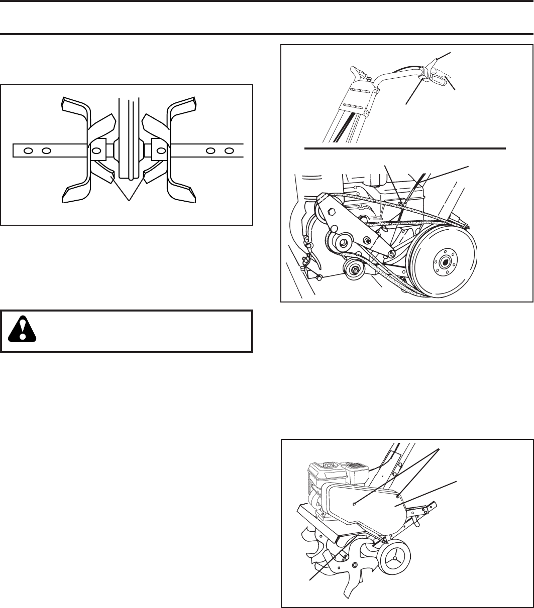
TO REPLACE V-BELTS (See Figs. 21 and 22)
Replace V-belts if they have stretched considerably or if
they show cracks or frayed edges. There are two (2) V-belts
- forward (inside) and reverse (outside).
Belt guard must be removed to service belts. See “TO
REMOVE BELT GUARD” in this section of manual.
NOTE: Observe carefully routing of both belts and lo ca tion
of all belt guides before removing belts.
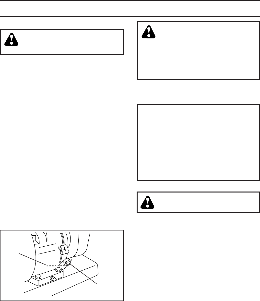
TO REMOVE BELT GUARD (See Fig. 20)
• Remove two (2) cap nuts and washers from side of
belt guard.
• Loosen (do not remove) tine shield nut on underside
of tine shield.
• Pull belt guard out and away from unit.
• Replace belt guard by reversing above procedure. Be
sure slot in bottom of belt guard is under head of tine
shield bolt and all nuts are tightened securely.
FIG. 20
CAP NUTS
AND WASH ERS
BELT
GUARD
TINE
SHIELD
NUT
14
SERVICE AND ADJUSTMENTS
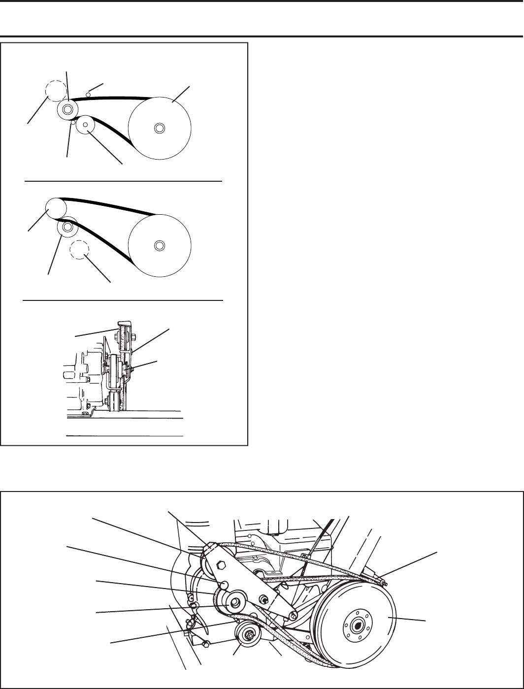
belts_10
FIG. 22
FORWARD MOTION
(INSIDE) V-BELT
ENGINE PULLEY
REVERSE
IDLER ARM
REVERSE
IDLER PULLEY
IDLER
ARM PIN
FIG. 21
FORWARD
IDLER PULLEY
REVERSE
IDLER
PULLEY
ENGINE PUL-
LEY
FRONT VIEW REFERENCE
REVERSE (OUTSIDE) V-BELT
FORWARD MOTION (INSIDE) V-BELT
TRANS MIS SION
PUL LEY
BELT GUARD
BOLT
BELT
GUIDE
REVERSE
IDLER PULLEY IDLER
ARM PIN
ENGINE
PULLEY
REVERSE (OUTSIDE)
V-BELT
FORWARD IDLER
PUL LEY
REVERSE
IDLER PULLEY
ENGINE PULLEY
BELT GUIDE TRANS MIS SION
PULLEY
BELT GUIDE
FORWARD
IDLER PULLEY
ENGINE
TO AD JUST CARBURETOR
The carburetor has been preset at the factory and ad just ment
should not be necessary. However, engine per for mance
can be affected by dif fer enc es in fuel, tem per a ture, al ti tude
or load. If the carburetor does need ad just ment, contact
your nearest authorized service center/de part ment
IMPORTANT: NEVER TAMPER WITH THE ENGINE GOVERNOR,
WHICH IS FACTORY SET FOR PROPER ENGINE SPEED.
OVER SPEED ING THE ENGINE ABOVE THE FACTORY HIGH
SPEED SETTING CAN BE DANGEROUS. IF YOU THINK THE
ENGINE-GOVERNED HIGH SPEED NEEDS ADJUSTING,
CONTACT YOUR NEAREST AUTHORIZED SERVICE CENTER/
DEPARTMENT, WHICH HAS THE PROPER EQUIP MENT AND
EXPERIENCE TO MAKE ANY NEC ES SARY ADJUSTMENTS.
BELT REMOVAL
• Remove reverse idler pulley from idler arm.
• Remove reverse (outside) V-belt.
• Remove forward (inside) V-belt from transmission pul ley
fi rst and then from engine pulley.
BELT REPLACEMENT
• Install new forward (inside) V-belt to engine pulley fi rst
then to transmission pulley. Be sure belt is positioned
on inside groove of both pulleys, inside all belt guides
and rests on idler pulley.
• Before installing reverse (outside) V-belt, turn belt “in side
out”. Twist so wide, fl at surface of belt is to inside.
• Wrap V-belt around reverse idler pulley and re as semble
idler to idler arm. Tighten securely. Be sure belt is
between reverse idler pulley and idler arm pin.
• Install belt to outside groove of transmission pulley. Be
sure belt is inside all belt guides and rests on outside
groove of engine pulley.
CHECK TINE OPERATION
• See “TINE OPERATION CHECK” in this section of
manual.
REPLACE BELT GUARD

15
STORAGE
ENGINE OIL
Drain oil (with engine warm) and replace with clean oil. (See
“ENGINE” in the Maintenance section of this man ual).
CYLINDER(S)
• Remove spark plug.
• Pour 1 ounce (29 ml) of oil through spark plug hole into
cylinder.
• Pull starter handle slowly several times to distribute
oil.
• Replace with new spark plug.
OTHER
• Do not store gasoline from one season to another.
• Replace your gasoline can if your can starts to rust.
Rust and/or dirt in your gasoline will cause problems.
• If possible, store your unit indoors and cover it to give
protection from dust and dirt.
• Cover your unit with a suitable pro tec tive cover that
does not retain moisture. Do not use plastic. Plastic
cannot breathe which allows con den sa tion to form and
will cause your unit to rust.
IMPORTANT: NEVER COVER TILLER WHILE ENGINE AND
EXHAUST AREAS ARE STILL WARM.
Immediately prepare your tiller for storage at the end of the
season or if the unit will not be used for 30 days or more.
WARNING: Never store the tiller with
gasoline in the tank inside a build ing
where fumes may reach an open fl ame
or spark. Allow the engine to cool before
storing in any enclosure.
TILLER
• Clean entire tiller (See “CLEANING” in the Maintenance
section of this manual).
• Inspect and replace belts, if nec es sary (See belt re-
place ment in struc tions in the Service and Ad just ments
section of this manual).
• Lubricate as shown in the Maintenance section of this
manual.
• Be sure that all nuts, bolts and screws are securely
fastened. Inspect moving parts for damage, break age
and wear. Replace if necessary.
• Touch up all rusted or chipped paint surfaces; sand
lightly before painting.
ENGINE
FUEL SYSTEM
IMPORTANT: IT IS IMPORTANT TO PREVENT GUM DEPOSITS
FROM FORMING IN ESSENTIAL FUEL SYSTEM PARTS SUCH
AS THE CARBURETOR, FUEL FILTER, FUEL HOSE, OR TANK
DURING STORAGE. ALSO, EXPERIENCE INDICATES THAT
ALCOHOL BLENDED FUELS (CALLED GASOHOL OR USING
ETHANOL OR METHANOL) CAN ATTRACT MOISTURE WHICH
LEADS TO SEPARATION AND FORMATION OF ACIDS DURING
STORAGE. ACIDIC GAS CAN DAMAGE THE FUEL SYSTEM
OF AN ENGINE WHILE IN STORAGE.
• Empty the fuel tank by starting the engine and let it run
until the fuel lines and carburetor are empty.
• Never use engine or carburetor cleaner products in the
fuel tank or permanent.
• Use fresh fuel next season.
NOTE: Fuel stablizer is an acceptable alternative in
minimizing the formation of fuel gum deposits during
storage. Add stabilizer to gasoline in fuel tank or storage
container. Always follow the mix ratio found on stablizer
container. Run engine at least 10 minutes after adding
stablizer to allow the stabilizer to reach the carburetor.
Do not empty the gas tank and carburetor if using fuel
stabilizer.

16
Will not start 1. Out of fuel. 1. Fill fuel tank.
2. Engine not “CHOKED” properly. 2. See “TO START ENGINE” in the Operation section.
3. Engine fl ooded. 3. Wait several minutes before attempting to start.
4. Dirty air cleaner. 4. Clean or replace air cleaner cartridge.
5. Water in fuel. 5. Empty fuel tank and carburetor, and refi ll tank with
fresh gasoline.
6. Clogged fuel tank. 6. Remove fuel tank and clean.
7. Loose spark plug wire. 7. Make sure spark plug wire is seated properly on
plug.
8. Bad spark plug or improper gap. 8. Replace spark plug or adjust gap.
9. Carburetor out of adjustment. 9. Make necessary adjustments.
Hard to start 1. Throttle control not set properly. 1. Place throttle control in “FAST” position.
2. Dirty air cleaner. 2. Clean or replace air cleaner cartridge.
3. Bad spark plug or improper gap. 3. Replace spark plug or adjust gap.
4. Stale or dirty fuel. 4. Empty fuel tank and refi ll with fresh gasoline.
5. Loose spark plug wire. 5. Make sure spark plug wire is seated properly on
plug.
6. Carburetor out of adjustment. 6. Make necessary adjustments.
Loss of power 1. Engine is overloaded. 1. Set depth stake and wheels for shallower tilling.
2. Dirty air cleaner. 2. Clean or replace air cleaner cartridge.
3. Low oil level/dirty oil. 3. Check oil level/change oil.
4. Faulty spark plug. 4. Clean and regap or change spark plug.
5. Oil in fuel. 5. Empty and clean fuel tank and refi ll, and clean
carburetor.
6. Stale or dirty fuel. 6. Empty fuel tank and refi ll with fresh gasoline.
7. Water in fuel. 7. Empty fuel tank and carburetor, and refi ll tank with
fresh gasoline.
8. Clogged fuel tank. 8. Remove fuel tank and clean.
9. Spark plug wire loose. 9. Connect and tighten spark plug wire.
10. Dirty engine air screen. 10. Clean engine air screen.
11. Dirty/clogged muffl er. 11. Clean/replace muffl er.
12. Carburetor out of adjustment. 12. Make necessary adjustments.
13. Poor compression. 13. Contact an authorized service center/department.
Engine overheats 1. Low oil level/dirty oil. 1. Check oil level/change oil.
2. Dirty engine air screen. 2. Clean engine air screen.
3. Dirty engine. 3. Clean cylinder fi ns, air screen, muffl er area.
4. Partially plugged muffl er. 4. Remove and clean muffl er.
5. Improper carburetor adjustment. 5. Adjust carburetor to richer position.
Excessive bounce/ 1. Ground too dry and hard. 1. Moisten ground or wait for more favorable soil
diffi cult handling conditions.
2. Wheels and depth stake incorrectly adjusted. 2. Adjust wheels and depth stake.
Soil balls up or clumps 1. Ground too wet. 1. Wait for more favorable soil conditions.
Engine runs but tiller 1. Tine control is not engaged. 1. Engage tine control.
won’t move 2. V-belt not correctly adjusted. 2. Inspect/adjust V-belt.
3. V-belt is off pulley(s). 3. Inspect V-belt.
Engine runs but labors 1. Tilling too deep. 1. Set depth stake for shallower tilling.
when tilling 2. Throttle control not properly adjusted. 2. Check throttle control setting.
3. Carburetor out of adjustment. 3. Make necessary adjustments.
PROBLEM CAUSE CORRECTION
TROUBLESHOOTING POINTS
17
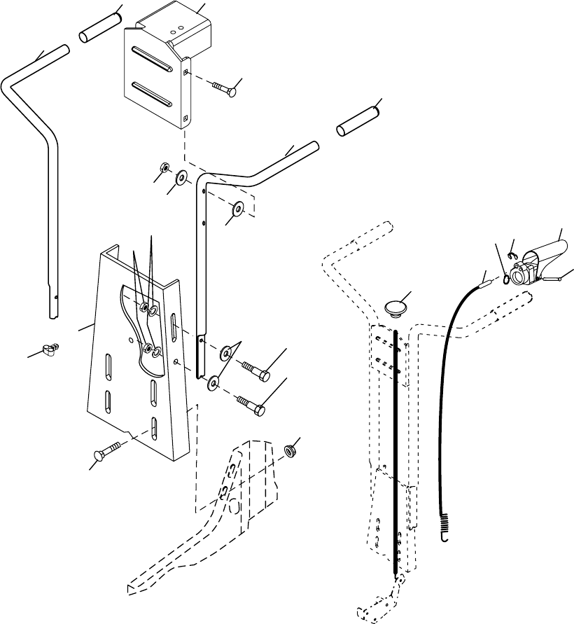
1 532 40 51-08 Bracket Handle
2 872 14 05-12 Bolt, Carriage 5/16-18 unc x 1-1¦2
3 532 00 92-66 Grip, Handle
4 532 16 63-76 Handle, L.H.
5 873 68 05-00 Locknut, Crown 5/16-18
6 819 11 11-16 Washer 11/32 x 11/16 x 16 Ga.
7 819 12 14-14 Washer 3/8 x 7/8 x 14 Ga.
8 874 76 05-20 Bolt, Hex Hd. 5/16-18 x 1-1/4
9 874 76 05-16 Bolt, Hex Hd 5/16-18 x 1
10 810 04 05-00 Washer, Lock 5/16
11 873 22 05-00 Nut, Hex 5/16-18
12 898 00 01-29 Nut, Flanged 5/16-18
13 532 18 08-47 Bolt, Carriage 5/16-18 x 3/4 Gr. 5
KEY PART
NO. NO. DESCRIPTION
KEY PART
NO. NO. DESCRIPTION
14 532 40 51-09 Panel, Handle
16 532 16 63-77 Handle, R.H.
18 532 16 68-68 Cable, Control, Tine
19 532 15 12-29 Lever, Control, Tine
20 532 15 48-05 Pin, Pivot
21 812 00 00-27 Ring, Klip
28 819 13 13-12 Washer 13/32 x 13/16 x 12 Ga.
29 812 00 00-59 Retaining, Ring
43 532 18 81-77 Cable Assembly, Reverse
44 532 18 15-80 Clip
NOTE: All component dimensions are given in U.S.
inches. 1 inch = 25.4 mm
1
2
3
3
16
4
5
6
78
9
12
28
14
44
13
11
10
handle_assy_34
18
43
29
19
20
21
REPAIR PARTS
TILLER - - MODEL NUMBER PPFT55 (96081000700)
HANDLE ASSEMBLY
18
KEY PART
NO. NO. DESCRIPTION
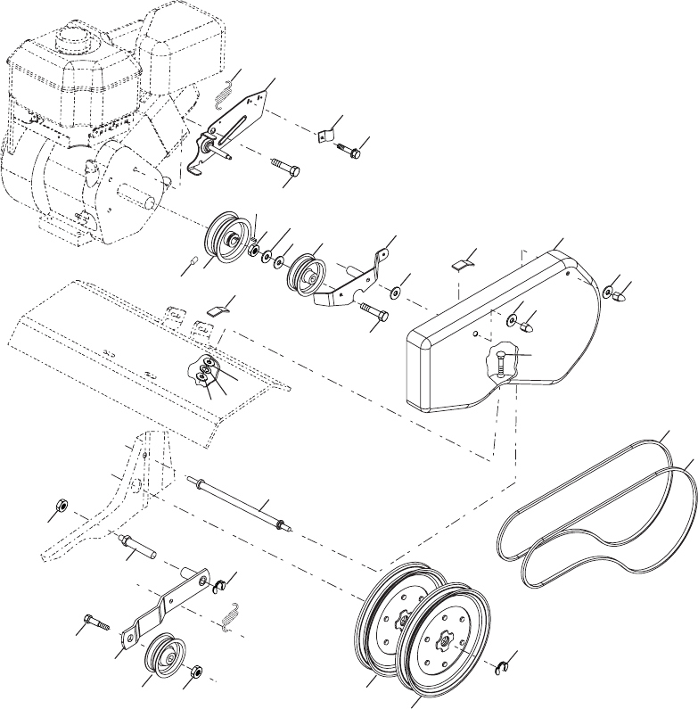
19 532 18 85-02 Bolt, Belt Guard
20 812 00 00-36 Ring, Klip
21 873 35 06-00 Nut, Hex, Jam 3/8-16
22 532 16 18-06 Pulley, Idler
23 532 17 53-77 Arm, Idler
24 874 76 06-20 Bolt, Hex 3/8-16 x 1-1/4
25 532 10 69-68 Shaft, Idler Arm
26 873 35 05-00 Nut, Hex, Jam 5/16-18
27 873 22 04-00 Nut, Fin Hex 1/4-20
28 810 04 04-00 Washer LK Hvy Helical 1/4
29 532 10 92-27 Pad, Idler
30 823 20 04-04 Screw, Set , Socket, Headless
C.P. 1/4-20 x 1 /4
31 532 10 11-89 Sheave, Engine
32 532 15 12-23 Pulley, V-Groove, Trans.
41 532 18 03-07 Spring
42 532 13 89-09 Spacer
KEY PART
NO. NO. DESCRIPTION
1 532 18 03-77 Assembly, Bracket, Belt Guard
2 532 00 94-84 Clip, Cable
3 532 08 67-77 Screw, Hex, Washer Hd., Slotted,
Thd. Cutting #10-24 x 1/2 Type D
4 874 61 08-12 Bolt, Hex 1/2-20 x 3/4
5 873 68 06-00 Nut, Hex Lock 3/8-16
6 819 13 13-16 Washer 13/32 x 13/16 x 16 Ga.
7 532 00 20-09 Pulley, Idler, Reverse
8 532 18 03-23 Assembly, Arm, Reverse Idler
9 874 76 06-28 Bolt, Hex 3/8-16 x 1-3/4
10 532 40 51-10 Guard, Belt
11 819 09 10-16 Washer 9/32 x 5/8 x 16 Ga.
12 532 10 42-13 Nut, Cap 1/4- 20
13 872 14 04-06 Bolt, Carriage 1/4-20 x 3/4
14 532 13 30-35 V-Belt (Forward Motion)
15 532 00 26-14 V-Belt (Reverse)
16 812 00 00-28 Ring, Retainer
17 532 00 26-49 Key, Square
18 532 15 12-36 Pulley, Flat, Trans. NOTE: All component dimensions given in U.S. inches.
1 inch = 25.4 mm
41 1
2
3
4
542
678
29
11
9
17
31
30 29
11
11
11
10
14
15
12
12
13
16
19
32
18
20
25
21
22
23
24
26
28
27
belt_guard_14
REPAIR PARTS
TILLER - - MODEL NUMBER PPFT55 (96081000700)
BELT GUARD AND PULLEY ASSEMBLY
19
6
7
8
13
9
10
11
22
15
3
24
54
7
4
5
17
16
18
18
21
17
16
2
2
13
24
19
19
20
20
wheel_d.stake_2
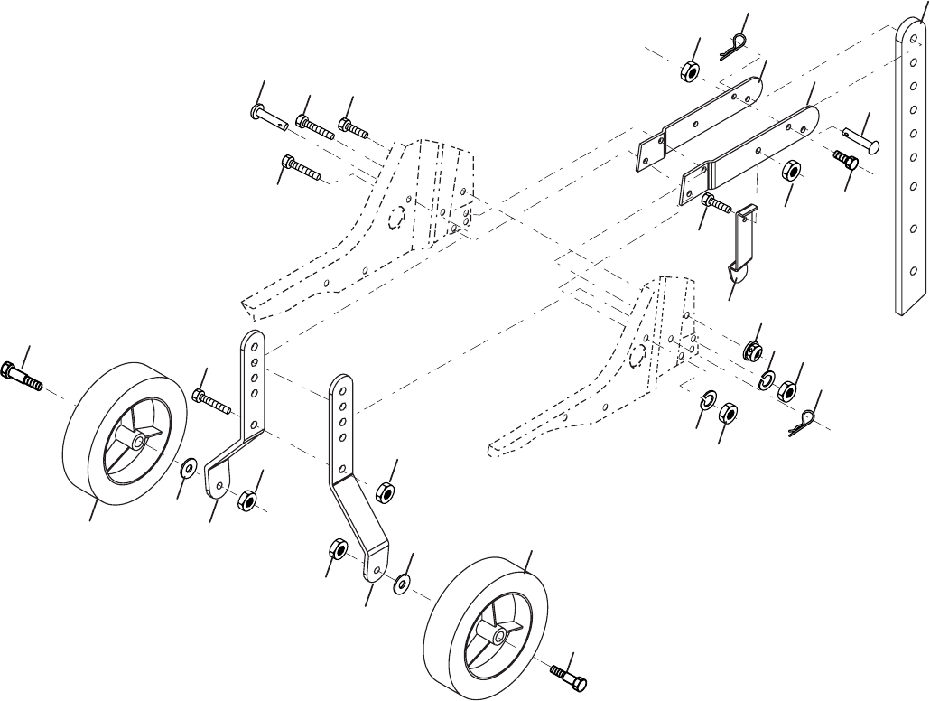
1 532 00 91-94 Pin, Clevis
2 874 76 05-20 Bolt, Hex 5/16-18 x 1-1/4
3 874 76 05-12 Bolt, Hex 5/16-18 x 3/4
4 873 22 05-00 Nut, Hex 5/16-18
5 810 04 05-00 Washer, Lock 5/16
6 873 80 06-00 Locknut, w/washer 3/8-16
7 532 12 49-61 Clip, Hairpin
8 532 12 46-59 Support, Depth Stake, R.H.
9 532 12 22-33 Stake, Depth
10 532 00 03-26 Pin, Clevis
11 874 78 06-28 Bolt, Hex, Fin 3/8-16 x 1-3/4
13 532 14 92-09 Support, Depth Stake, L.H.
KEY PART
NO. NO. DESCRIPTION
15 532 12 47-24 Spring, Stake
16 532 12 11-17 Bolt, Shoulder
17 532 00 91-88 Wheel
18 819 13 13-11 Washer 13/32 x 13/16 x 11 Ga.
19 532 12 47-07 Bracket, Wheel
20 873 68 06-00 Locknut, Crown 3/8-16
21 874 76 05-16 Bolt, Hex 5/16-18 x 1
22 873 80 05-00 Locknut, w/insert 5/16-18
24 873 97 05-00 Nut Lock Hex Flange
KEY PART
NO. NO. DESCRIPTION
NOTE: All component dimensions given in U.S. inches.
1 inch = 25.4 mm
REPAIR PARTS
TILLER - - MODEL NUMBER PPFT55 (96081000700)
WHEEL AND DEPTH STAKE ASSEMBLY
20
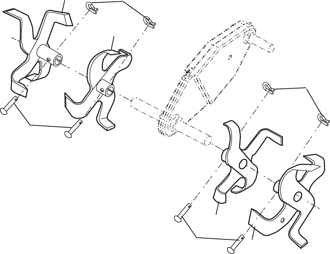
REPAIR PARTS
TILLER - - MODEL NUMBER PPFT55 (96081000700)
TINE ASSEMBLY
KEY PART
NO. NO. DESCRIPTION
1 532 15 69-26 Tine, Outer, R.H.
2 532 12 46-60 Retainer, Spring
3 532 15 69-24 Tine, Inner, R.H.
4 532 15 69-23 Tine, Inner, L.H.
5 532 15 69-25 Tine, Outer, L.H.
6 532 00 49-29 Pin, Clevis
KEY PART
NO. NO. DESCRIPTION
3
1
6
4
5
6
2
2
tine_ipb_3
21
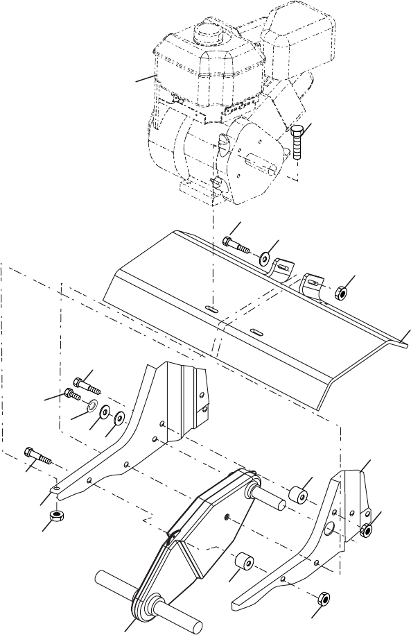
REPAIR PARTS
TILLER - - MODEL NUMBER PPFT55 (96081000700)
TRANSMISSION
KEY PART
NO. NO. DESCRIPTION
14 532 00 91-73 Spacer, Split
16 819 09 14-12 Washer 9/32 x 7/8 x 12 Ga.
17 819 09 20-16 Washer 9/32 x 1-1/4 x 16 Ga.
18 810 04 04-00 Washer, Lock 1/4
19 874 61 04-12 Bolt, Hex 1/4-28 x 3/4 Gr. 5
20 - - - - - - - Engine, Briggs Model 126302
Order parts from engine manufac-
turer
2
3
5
6
8
11
16
17
11
10
7
19
14
10
12
18
10
14
1
20
transmission_12
KEY PART
NO. NO. DESCRIPTION
1 874 76 05-24 Bolt, Hex 5/16-18 x 1-1/2 Gr. 2
2 874 78 06-52 Bolt, Hex, Fin 3/8-16 x 3-1/4
3 819 13 13-11 Washer 13/32 x 13/16 x 11
5 873 90 06-00 Nut Lock Flg 3/8-16 unc
6 532 40 51-11 Shield, Tine
7 532 18 81-95 Bracket, Engine, R.H.
8 532 16 58-34 Bracket, Engine, L.H.
10 873 97 05-00 Nut Lock Hex Flg
11 532 18 79-12 Bolt, Shoulder
12 532 15 12-22 Transmission NOTE: All component dimensions given in U.S. inches.
1 inch = 25.4 mm
22
REPAIR PARTS
TILLER - - MODEL NUMBER PPFT55 (96081000700)
DECALS
KEY PART
NO. NO. DESCRIPTION
1 532 40 36-53 Decal, Logo
2 532 40 37-13 Decal, Logo
3 532 15 73-78 Decal, HP, Reverse
4 532 18 99-36 Decal, Reverse, Tine Control
5 532 12 04-31 Decal, Hand Placement
6 532 40 36-89 Decal, Eng. Tiller
7 532 19 48-08 Decal, OHV.
8 532 16 22-15 Decal, Tine Shield Wrng. Dom
9 532 15 73-81 Decal, Hvy Duty
10 532 17 35-38 Decal, Rewind Intek
11 532 16 88-69 Decal, Tick Mark
12 532 12 00-75 Decal, Warning
- - 532 40 36-61 Manual, Owner’s
1
2
8
7
3
4
5
9
10
11
6
12
23
SERVICE NOTES