Power Instruments PIDEL010901900 Telemetry Data Acquisition and System Control Data Logger User Manual 07 Product Manual
Power Instruments Pte Ltd Telemetry Data Acquisition and System Control Data Logger 07 Product Manual
User Manual

eGenKit
Product Manual
Model:
Logger 1.0
1
C
E Declaration of Conformity
This
device complies with CE Rules.
Operation is subject to the following two conditions:
1.
T
his device may not caus
e harmful int
erference.
2.
T
his device must accept any interference received, including interference that
may cause
undesired operation.
This equipment has been tested and found to comply with the limits fo
r a Class B
product.
FCC Declaration of Conformity
This device co
mplies with Part 15
b
of the FCC Rules. Operation is subject to th
e following two
conditions.
1.
T
his device may not cause
harmful interference.
2.
This
device must accept any interference received, including interference that may cause
undesired operation.
This
equipment has been tested and found to comply with the limits for a Class B digital device,
pursuant to Part 15 of the FCC Rules. These limits are designed to provide reasonable protection
against harmful interference.
This equipment generates, uses, and
can radiate radio frequency energy
and, if not installed and used in accordance with the instructions, may cause harmful interference to
radio communications.
However, there is no guarantee that interference will not occu
r in a particular
installation.
I
f this equipment does cause harmful interference to radio or
television reception, which
can be determined by turning the equipment off and on, the user is encouraged to try to correct the
interference by one or more of the following measures:
Reorient or
relocate the receiving antenna.
Increase the separation between the equipment and the receiver.
Connect the equipment to an outlet on a circuit other than the one to which the receiver is
connected.
Consult the dealer or an experienced radio/ TV technician
for help.
Type Approval and Certifications
This device
has been tested and issued
with the following countries Telecommunication
T
ype
Approval:
Europe (CE)
USA (FCC)
Brunei (JTB)
Cambodia (ISC)
Indonesia
(DGPOSTEL)

2
Malaysia (SIRIM)
Philippines (NTC)
Sing
apore (iDA)
Thailand (NTC)
Vietnam (
DGPT)
Disclaimer
This
product
is
not intended for use in medical,
life saving, or life sustaining applications.
Power
Instruments
may make changes to specifications and p
roduct descriptions at any time
without notice.
Power Instruments
reserves the right to make improvements or
/ and
changes to this manual, or to the
products
or
/ and
the programs described in this manual
at any time.
The i
nformation provided in this
manual is intended to be accurate and reliable. Howeve
r,
Power Instruments
assumes no
responsibility
for its use, or for any infringements on the rights of third parties that may result from its use.
Intended
Audience
The Product Guide is intended for technically qualified personnel. It is not intended for g
eneral
audiences.
Box Contents
eGenKit
Data
Logger set
(
~
160
mm x 128
mm x 85.2
mm)
GSM/
GPRS Antenna
(Quad band)
GPS Antenna
2
m
eter
shielded
RJ45
Ethernet
c
ross
cable
Quick Startup Guide
This User Manual
Email Technical Support:
eGenKit@powerinstruments.com.sg
Download updated
product
information,
animated demo guide,
user manuals and drivers:
http://www.eGenKit.com/
Phone: +65
-
6288 1183
40
Toh Guan Road
East
#01
-
62
Singapore 608582
Singapore
3
Table of Contents
1.
Product Specifications
Page 5
2.
Introduction
Page 7
3.
Configuring the e
GenKit Logger via the Debug Port
Page 10
3.1.
System Settings
Page 10
3.2.
GPRS Settings
Page 10
3.3.
Ope
rating Mode
Page
11
3.4.
Local Network Setting For LAN Application
Page
12
4.
Product Hardware Overview
Page
13
4.1.
Front View
Page
13
4.2.
Rear View
Page
13
4.3.
LED Indications
Page
13
4.4.
Connectors Descriptions
Page
14
5.
eGenK
it Hardware Installation
Page
15
6.
eGenKit Remote Monitoring and Control Website
Page
16
7.
Appendix A:
Page
18
Gen
-
set Controller Model and Version Supported with the eGenKit Data Logger
8.
Frequency Ask Questions
Page
19

4
1.
P
roduct Specification
s
General Specification
Processor:
Motorola MPC8241, 32
-
bit PowerPC 603e core (200MHz)
GSM/ GPRS Module:
Wavecom Q24 Automotive
SDRAM:
32 MB
On Board Flash:
8 MB
Data Logging Memory:
1GB
Power Consumption:
GPRS
Searching (220mA @ 24V
DC
)
GPRS connected (160mA @ 24V
DC
)
Initial start
-
up current: 1A
Input
Voltage
Range
:
9V
DC
to 32V
DC
Input Voltage (Nominal):
24V
DC
LED Indicator:
Power On, LAN port, Debug port, GPS, GPRS connected
Firmware Upgrade:
Throu
gh Debug Port (Cross LAN cable supplied)
Parameter setting:
Through Debug Port (Cross LAN cable supplied)
Protocol supported:
TCP/IP
, PPP
+ SSH
Security:
VPN and SSH Encryption
Interface to equipment:
RS485 (2 wires)
+ GND
Build in Watch Dog:
Yes
GSM/
GPRS Specification
Frequency Band:
Quad Band (
850MHz, 900MHz,
1800
MHz, and 1
9
00MHz
)
GPRS Multi
-
slot:
Class 10
GPRS Module Approval:
GCF, CE, FCC
Code Scheme:
CS1, CS2
Output Connector:
SMA Female Reverse Polarity
GPS Specification
Acquisitio
n Rate:
Cold/ Warm/ Hot: 42/ 38/ 1 sec (Average)
NMEA Protocol:
GGA, GSA, GSV, RMC, VTG, GLL
Datum:
WGS
-
84
Accuracy Position:
10m @ 2D
Sensitivity:
Cold/ Warm/ Tracking: 30/ 15/ 13 dB
-
Hz

5
Output Connector:
SMA Female
Mechanical Specification:
Operating Temperature:
0
o
C to 50
o
C
Operating Humidity:
5% to 95%
Storage Temperature:
-
20
o
C to
+
85
o
C
Dimension (mm):
160 (L) x 128 (W) x 85.2 (H)
Weight:
~
1.3 kg
Product Class (EMC):
Class B
Safety Class:
Class 3
Regulatory Approval:
F
CC
and CE Mark
Type Approval:
Brunei (JTB)
Cambodia (ISC)
Indonesia (DGPOSTEL)
Malaysia (SIRIM)
Philippines (NTC)
Singapore (iDA)
Thailand (NTC)
Vietnam (DGPT)
SIM card Holder:
3V/ 1.8V
Wall Mount:
Yes
Din
-
Rail:
Yes
6
2.
Introduction
T
his Product guide gives information about the installation, and setting of t
he
e
GenKit
data logger
device.
The
e
GenKit
is a T
elemetry data acquisition and system control
data
logger which primary purpose
is
to be used in stationary or mobile Diesel
-
Power
-
G
enerator
-
Control (Gen
-
set Controller) facilities.
How
ever this data logger device may
also be used for other data monitoring and control industrial
equipments (i.e. Power Metering, Programmable Logic Control
–
PLC, etc) that
have
a RS485
Modbus interface
to
the logger. Please check
A
ppendix A
for the type and mo
del of the
Gen
-
set
controller
equipments supported with
e
GenKit
.
The main functions and features of
e
GenKit
logger are to provide:
Remote monitoring and
simple
diagnosti
c of power generator equipm
ents via the internet.
Send control signal to remote Gen
-
set Controller.
Send
SMS
and email to al
ert Gen
-
set service personnel and
engineers when a Gen
-
set
Controller alarm has been trigger, which requires technical personnel attention and servicing.
Data
logging
and transmission
of Gen
-
set activities.
Reports the earth geographic position of the
e
GenKit
logger device using Global Positioning
Sys
tem (GPS), and therefore locates
the power Gen
-
set equipments location
on the
server
web
page
.
The
eGenKit
is a
standalone data logger (Remote Terminating Unit
-
RTU) whic
h can be connected to
most
diesels Gen
-
set Controller which has a RS485 Modbus interface. The RS485 Modbus is the
most common serial interface found in most Gen
-
set Controller and industrial equip
ments. Via the
two wires RS485
Modbus
interface the
e
GenKit
data logger is able to monitor the status of the
generator, and to send out signals that control the generator. Service personnel located anywhere in
the world who needs to check the status or s
end out control signals to the Gen
-
set Controller can now
do so once they are accessed to the Master Terminating Computer Server via the internet, which the
e
GenKit
logger communicates to.
The
e
GenKit
standalone data logger has two different options of con
necting to its Computer Server
(housed and maintain
ed by Power Instruments
in Singapore
). It can either connect using Ethernet
LAN cable or wireless GPRS (a GSM SIM card with GPRS enabled from the local service provider is
required) connection. The progr
ammable firmware inside the logger devices will decide whether it
will choose to connect using LAN or GPRS. The default setting is GPRS. Once powered on the
logger will connect to it’s service provider and link itself to the
e
GenKit
default
Server locate
d in
Singapore via the internet. You may also be connected to additional servers maintained in other parts

7
of the world to speed up the connectivity depending on your location. Authorized service personnel
each with an individual login user name and pass
word shall be able to logon to the
e
GenKit
(
http://www.eGenKit.com
) server
webpage
to monitor and control the whole event happening at the
generator side
.
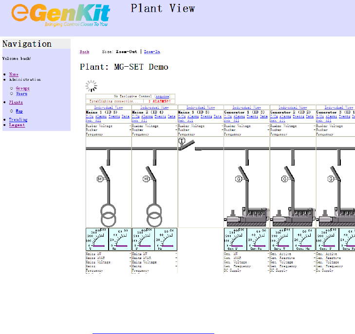
The server webpage is specially designed to provide a clear
view animated
circuit
diagram
of the
diesel
power generator
, busbar
and circuit breakers status and conditions. Various
individual and collective parameters like Line and Phase Voltage, Current, kW, kVA, kVAR,
Frequency, Power Factor, logging events and a
larm signals, etc are constantly updated and archived
onto the server computer
system
, enabling personnel to remotely access all information. In the event
when the internet connection is down or the GPRS signal is lost, the parameters of the generator
rel
ative to time are being captured and
saved
on to the 1GB USB flash memory inside the
eGenKit
RTU data logger. These collected data information will then be sent back to the server to be archived
once internet connection is established again.
During fault
detection when the generator controller
issues an autonomous alarm signal due to generator malfunction or drastic fluctuation in measurement
parameters, the
e
GenKit
logger will capture the alarm status, update the
serv
er. The system will
activate a
SMS
au
tomatically to alert the generator plant duty service personnel of the warning status
as soon as the alarm is raised on the unit. At the same time the server will also issue an email to
inform designated personnel on the warning alarm event.
There is a b
uilt in GPS module inside the
e
GenKit
logger which purpose is to identify it’s own geographical position and therefore the
generator facility location. The purpose for this feature is to provide geographical identification of
each generator location when
managing multiple power generator facilities. This feature also eases
tracking the location of mob
ile diesel power generators.
The
e
GenKit
logger is designed to
operate
at 24 hours, 7 days a week monitoring of the diesels power
generators.
In the event w
hen GPRS is disconnected deliberately or due to GSM network failure, all
data events will be log and saved inside the logger
internal memory.
The system has an option
to
allow user to
operates in GPRS sleeping mode function which the logger
will be activat
e via SMS
(automatically send out by Power Instruments international Bulk SMS
service)
to connect to the internet server once a user is log in to the server webpage to view the plant
activity, thus optimizing
the GPRS connection duration. The GPRS connect
ion remains connected for
an hour even after the user has log off from the webpage. Thereafter the logger
will go into GPRS
sleeping mode again.
8
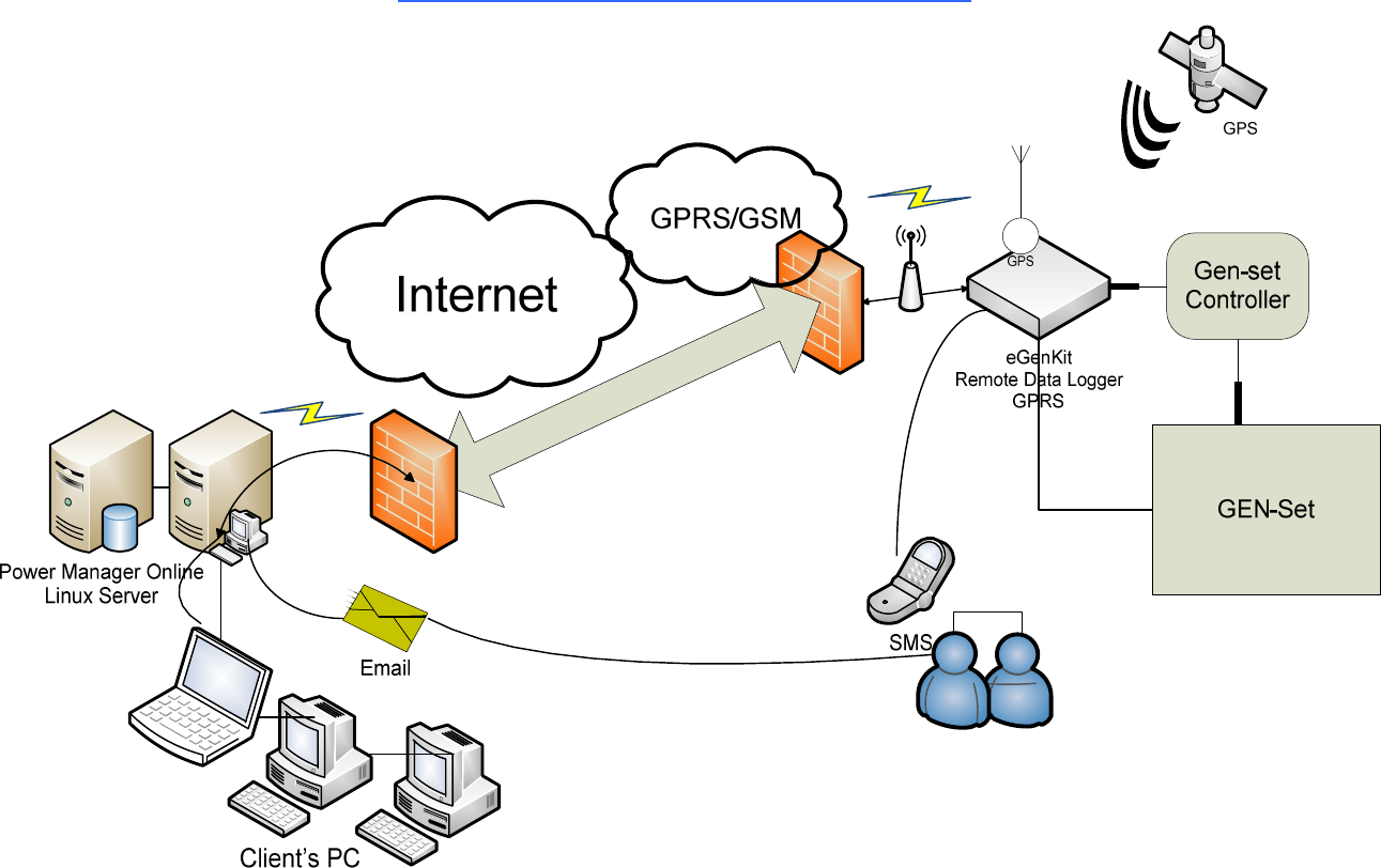
eGenKit Communications
Network Description
S
e
c
u
r
e
V
P
N
T
u
n
n
e
l
9
3.
Configuring the
eGenKit
Log
ger
via the Debug Port
C
onnect the Debug port of the logger to the RJ45 socket of a computer or Notebook using
the Cross Ethernet cable provided.
Go to Window Internet Explorer Web Page
Enter: http//192.168.100.1
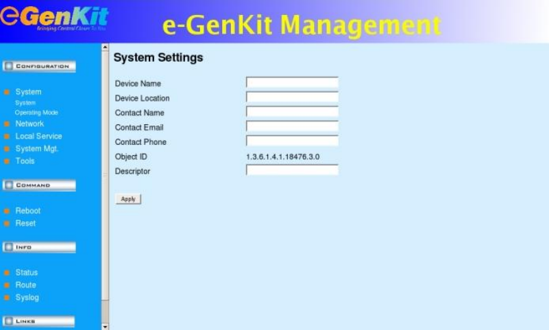
3.1
System Settings
Go System Settings.
T
he system setting will synchronize with the settings found at the Power Instruments server
and will update itself accordingly when the eGenkit data logger is connected to the server.
However user can choose to update
the following information and click ‘A
pply’ to update
the server information.
3.2
GPRS Setting
s
Go to GPRS Settings.
Enable/ check the GPRS box when using GPRS mode
. Default setting is GPRS.
Uncheck
this box
only
when using the Ethernet LAN option.
Enable/ check the Auto Mode box.
Ente
r a
n
APN description name.
Enter your SIM card service provider call number.
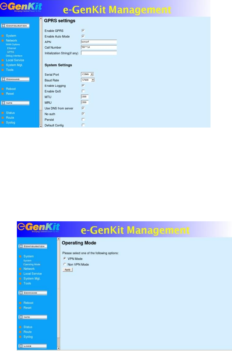
10
System settings leave it as default.
3.3 Operating Mode
Select VPN or Non VPN mode dependi
ng
on your type of SIM card provided by your
GSM
service provider.
Default setting
is VPN mode.
11
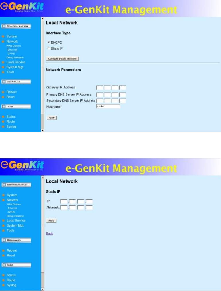
3.4
Local Network
Setting
For LAN Application
Go to Local Network setting
S
elect DHCPC
for dynamic IP address.
Default is DHCPC
Select only Static IP only when you have a permanent IP address.
Enter the Gateway IP address, primary and
secondary DNS server IP accordingly
under
Network Parameters
when Static IP is selected.
Enter the Static IP Address and Netmask
12
4.
Product Hardware Overview
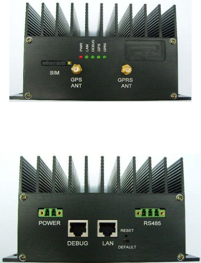
4.1
Front
View
4.2
Rear
View
4.3
LED Indications:
PWR
: Power Suppl
y Indication. Solid Red when DC supply is on
LAN
: Solid Green when Ethernet LAN connection is connected to a LAN
hub/ switch
or
router using a straight Ethernet cable.
DEBUG
: Solid Green when connected to computer Ethernet com port using a cross cable.
G
PS
: Blinking Green
when connected to a GPS antenna searching/ receiving satellite signals.
GPRS
: Solid Green when is not detecting or synchronize with any GSM frequency band;
Blinking Green when is synchronized with
one of the GSM frequency or
transmittin
g data.
+
-
-
+
GND
13
4.4
C
onnectors
Descriptions
GPS ANT
:
‘
SMA Female
’
for connecting to
the
GPS Antenna provided.
GPRS ANT
:
‘
SMA Female Reverse Polarity’ for connecting to the GPRS Antenna provided.
SIM
: SIM card holder slot for placing the GSM/ GPRS SIM card provided b
y your mobile
network service provider.
POWER
: DC supply (9V to 32V range) input.
Note the + positive and
–
negative polarity
.
RS485: RS485/ Modbus signal lines. Note the + positive and
–
negative
polarity
of the
differential signal lines.
Connect the G
ND point when applicable.
LAN
: 10/ 100 MBPS Ethernet LAN port. Connect using
an
Ethernet straight cable to a
hub/
switch
or
router
.
DEBUG
:
Debug Port for system setting, configuration and firmware upgrade. Connect using
an
Ethernet cross cable to a compu
ter.
RESET
: Hardware reset button to reset/ reboot the full system during a system hang.
Insert a
pointed object into the Reset hole to activate
reset
. Alternatively switch On/ Off the DC Input
Power Supply.
DEFAULT
:
Switch to default setting for servic
e personnel used only.
* Please do not unscrew the
front and real
panel
screws or attempt to remove the front and real panel
covers.
14
5.
eGenKit
Hardware Installation
5.1.
Using GPRS Connection
(Default
Setting
)
A SIM card with
GPRS
data enable
is needed.
D
elete any SMS messages from
the
SIM card
and d
isable
any
PIN code request so it w
ill not prompt for a PIN code when
turning on.
Use a pointed object to press on the pin
on the right
beside the SIM card holder to push out the
SIM car
d holder sl
ot. Place your GSM (
GPRS
enabled)
SIM card into the card holder and
insert it back into the
SIM
slot.
Connect the GPRS antenna to the
‘
Female
SMA
RP’ GPRS connector port.
Connect the GPS antenna to the
‘
Female
SMA
’
GPS
connector
.
Connect the RS485 + and
–
connections
to the
Gen
-
set controller RS485 + and
–
connections
respectively
.
Connect
the GND
connection when
applicable.
Connect the DC
(9V to 32V
) input supply + and
–
to a DC supply which can supply
at least up
to 1A max current.
Turn on the supply.
5.2.
Using LAN Connection
C
onnect the LAN port of the logger to the RJ45 socket of a hub/
switch or
a router (L
AN side
of the router) using a straight
Ethernet cable.
Connect the GPS antenna to the
‘
Female
SMA
’ GPS
con
nector.
Connect the RS485 + and
–
connect
ions
to the
Gen
-
set controller RS485 + and
–
connections
respectively
.
Connect the GND connection when applicable.
Connect the DC
(9V to 32V
) input supply + and
–
to a DC supply which can supply
at least up
to 1A m
ax current.
Turn on the supply.
15
6.
eGenKit
Remote
Monitoring and Control
Website
The
remote computer
recommended
minimum b
asic operating system for viewing and
operating
the eGenkit webpage
are:
i.
Operating System
:
Microsoft
Windows
2000/ Windows XP
ii.
Web
B
rower
: Microsoft Internet Explorer
7 and above
iii.
CPU
: Intel
Pentium 4/
Intel Celeron
2
GHz
iv.
Memory
(DDR)
:
512
MB
v.
LAN port
: 10/
100
MBPS
vi.
Internet C
onnect
ion S
peed
: 1
MBPS
Using a remote computer which is already connected to the internet, go to the Internet Explorer.
Enter the URL:
http://www.eGenKit.com/
Click ‘Login’
Enter your
User name and Password provided
to you by Power Instruments eGenKit
system
administrator.
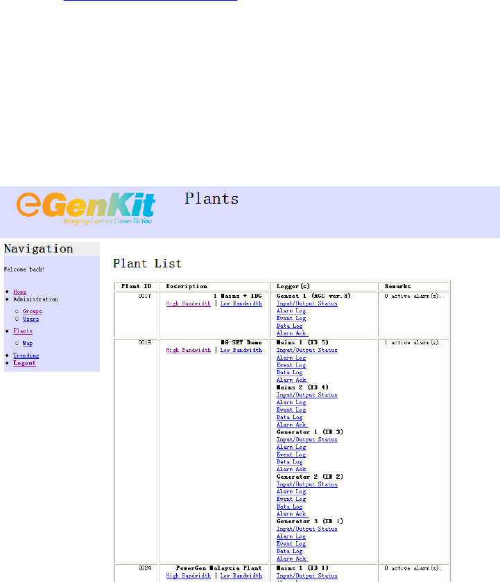
Click ‘Plant’ on the Navigation colu
mn on the
left side of the page to view all the co
nnected
generator plants description.
16
Click ‘High Bandwidth’ under one the ‘Plant ID Description’ on the Plant List Table of the
page to view an
d monitor the generator plant status, data and activities.
Please refer to the eGenKit
http://www.eGenKit.com/
website
user learner demo for
more
guid
es
and tips
on using the eGenKit Navigation webpage.

17
7.
Appendix A
:
Gen
-
set
Controller
Model and Version Support
ed
with the eGenKit
Data Log
ger
1.
Deif
Gen
-
set Controller
Deif
Automatic Gene
rator Controller, AGC
-
3
Deif Basic Generator Controller, BGC
Deif
Generator Paralleling Controller
, GPC
2.
Caterpillar
Caterpillar EMCP 3.3

18
8.
Frequently
Ask Questions
1)
What c
an eGenkit provides?
Allows remote monitoring, data logging, events reporting and control multiple sites such as
generators, power plants, water tank and equipments which needs remote monitoring services.
2)
Who requires such application?
Any fleet managemen
t companies, generator service maintenance provider or even power plant
owners who need remote access to their running power generators.
3)
What is GSM?
GSM
–
Global System for Mobile Communication is a digital mobile telepho
ne widely use in
today’s world.
GSM digitizes and send out
user data in time slot channel.
It operates at either 900
MHz or 1800 MHz frequency band. GSM 900/
1800 is called the EURO Band whereas GSM 850/
1900 is called US Band.
4)
What is GPRS?
The Global Packet Radio Services (GPRS) is a
n integrated part of GSM core networks that is
available to users of 2G
cellular communication systems.
It is a packet oriented Mobile Data
service that provides support to 3G based networks.
5)
What is APN?
Access Point Name (APN) is a network identity in
GPRS standard to identify the service or
network to which user can c
onnect within the GPRS network.
It is associated with access
characteristics, including security and method of dynamic addressing.
6)
What is VPN?
A secure Virtual Private Networks (VPN) th
at run as part of tr
usted channel of communication.
It
uses cryptographic tunneling protocols to provide the intended confidentiality such as blocking
snooping and packet sniffing.
7)
Can GPRS connection be set to sleep mode when not in use?
Yes, user can c
onfigure
eGenKit
into sleep mode condition and wakes up automatically
when
there is alarm triggered.
This will optimize GRPS bandwidth and data usage.
19
8)
Will the VPN connection disconnect unnecessarily?
It depends
on the
VPN networks provided by the respec
tive
Telco.
Signal strength and coverage
area is the key factor that contributes to the stability of data networks.
9)
How secure are eGenkit Server and
eGenKit data logger
?
eGenkit
server and e
GenKit
data logger
is using secure remote access (VPN) solution
s as a path of
communica
tion between client and server.
A secure modular router for hardware encryption and
firewalls is designed to provide secure data networks.
10)
How secure is VPN in GPRS networks?
Most telecommunication companies are offering public Ac
cess Point Name (APN) for secure data
access with standard protocols.
Private APN is only visible to within dedicated users.
11)
Can any
Modbus
equipment connect to
eGenKit
?
No, only
Modbus equipment
s
listed in Appendix A
is
support
ed
with the eGenkit.
12)
Can
user connect
the
eGenkit
data logger
without server?
No, e
ach
e
GenKit
is required to establish connection (Ethernet or GPRS) with the server placed at
centralize location.
13)
How to apply this VPN service from Telco?
User is required to request for GPRS data
service with end
-
to
-
end communication package.
14)
What is the available communication option in eGenkit?
GPRS
and Ethernet LAN
.
15)
What else does the user ne
ed besides purchasing the eGenKit
?
User will require
a
UserID and Password to eGenKit Server in orde
r
to view their plant.
One
UserID and Passw
ord is considered as a license. There are two
types of license:
Administrative
and User.
Administrative
:
This login license allows right
-
access to configure the plant
User:
T
his login license can only allow monito
ring, viewing and controlling.
User can sign
-
up multiple Administrative or User licenses depending on their requirements
16)
Can user use both Ethernet and GPRS connection at the same time?
No,
o
nly one connection mode can be selected for communication at any
single time.
20
17)
How eGenkit
data logger
communicates with the automation instruments such as Gen
-
Set
controllers?
It utilizes Modbus RTU protocol (2
-
wire) to communicate with Gen
-
Set Controllers.
18)
eGenkit
data logger
can be set as Master and/or slave. Can
user have multiple
e
GenKit
data
logger
as Master?
No, there can only be one Master
e
GenKit
data logger
connecting to multiple slave
e
GenKit
data logger
.
19)
How many gen
-
set can
a
e
GenK
it
data logger
handle
s at one time
?
Modbus RTU limit to 32 slaves with on
e (master) eGenkit
data logger
.
It is recommended to
connect maximum up to
4
-
6 slaves on one Master
eGenK
it
data logger
for optimum speed
performance.
20)
Can user use any GPRS SIM card for eGenkit to communicate with the server?
User is required to make sur
e their GPRS package comes with Public IP or VPN Services.
21)
Can user set different timing for GRPS connection with the server?
Yes,
u
ser can schedule the
connection with eGenKit server.
This can only be done from
Administrative login.
22)
What will eGenkit
react when system
hang
?
eGenKit
data logger
is equipped with internal watch dog mechanism that will auto
reboot if
system
hang
.
23)
D
uring sleep mode, is the
e
GenKit
data logger
able to send out SMS in the event alarm trigger?
Yes, once alarm signal is receiv
ed by the
e
GenKit
it will send out SMS be
fore establish GPRS
connection.
When connection to server through GPRS is established, the server will also send
an emai
l to the designated recipients
.
24)
How many users are provided when one account is created?
Stan
dard account comes with 1 administrative and 2 user license.
25)
Can I configure the plant layout admin level?
21
No, each plant layout can only be customized by super admin level. Only the Power Instruments
has th
e right to configure the plant.
User will need
to provide plant requirements to Power
Instruments for system setting.
Form will be provided prior to commissioning work.
26)
Can admin level determine the access privilege of normal user?
Yes, admin can limit the access privilege (plant list) of specific us
er.
27)
Can I use two
units of eGenkit
data logger
in one single plant layout?
Yes, we can configure 2 units of eGenkit
data logger
in one single plant.
28)
Can user login from two different
computers using one login license?
No,
the s
ystem does not allow multip
le login of the same license.
29)
How Global Positioning System (GPS) works?
GPS can pinpoint
e
GenKit
data logger
location anywhere on E
arth.
The GPS satellites transmit
signals to device on the ground and receivers passi
vely receive satellite signals.
It
works only
when GPS antenna is placed with access to ‘open sky’ which means line of sight to a GPS satellite.