Power Monitors E2003 Eagle Class PQ Wireless Power Monitor User Manual Eagle users manual 1203
Power Monitors, Inc. Eagle Class PQ Wireless Power Monitor Eagle users manual 1203
users manual

Eagle Class PQ Wireless™ Recorder
User’s Manual
Power Monitors Inc. 1-800-296-4120
1661 Virginia Avenue 540-434-4120
Harrisonburg, VA 22802 USA Fax: 540-432-9430
http://www.powermonitors.com

Eagle Class PQ Wireless™ Digital Recorder Manual
©2003 Power Monitors Inc.
All Rights Reserved
Contents subject to change without notice.
This version: November 2003
Corrections or ideas for this manual please e-mail: lbarker@powermonitors.com

Eagle Class PQ Wireless™ Digital Recorder Manual
Foreword
We founded Power Monitors Inc. (PMI) to provide state-of-the art, easy-to-use, and affordable electronic test equipment to the
power industry. Our products have been developed by working directly with electric utilities to determine their specific needs.
These products are designed for only one purpose: to collect and assist in the analysis of field-recordable data for electric
utilities.
The Eagle Class Recorder™ were developed with your needs in mind. We created them to meet the needs of a large utility,
and based their unique capabilities on our years of experience building versatile voltage recording and analysis equipment.
Inside lightweight, weatherproof, rugged enclosures, state-of-the-art electronics measure and record true RMS voltage and
current on four channel connections. The units require so little power; they operate on the voltage from one of the attached
lines. There are no batteries to recharge prior to use. Each unit has been individually calibrated to ensure high accuracy and
stability over a wide range of temperatures.
PMI recorders remain the only products on the market that will allow both electronic “stripchart” recording and a number of
specialized recording modes tailored to the power industry. The specialized reports are merged with unique data collection
techniques to provide accurate information that is easy to understand. Features such as flicker monitoring, event recording, and
min/max/Avg recording of both voltage and current make PMI recorders the ideal products for distribution monitoring.
The Recorder features:
• True RMS voltage and current measurement on each of four channels
• Programmable abnormal voltage recording
• On-site, real-time display of voltage, current and power via Palm PDA & PMIScan or PMIView Software
• Single-cycle response (16 msec)
• More than 122,000 samples per second
• 0-600 volt RMS operating range
• 0-10, 100, 500, 1000, and 5000 Amp current input ranges
• Up to 4,096K FLASH EPROM memory
• Memory capacity for more than one year of summary data, 500 event records, 500 records of significant change,
500 records of flicker data
• Rugged, weatherproof enclosure NEMA 4X
• All channels captured simultaneously in one cabinet
Recorder/WinScan™ graphs and reports include:
• Stripchart and histogram analysis for RMS voltage, RMS current, power factor, displacement power factor, real
power, apparent power, reactive power, volt-amps, frequency, and phase angle
• Power outage report
• Abnormal voltage report
• Current or voltage out of limits report
• Significant change report
• Event change report
• Flicker report
Because of these capabilities, the Eagle Class Recorder™ are the perfect instruments for analyzing and solving power quality
and quantity problems. After looking through this manual and using your Recorder, please contact us with any questions about
its operation, or with ideas for new features or products. We want you to be happy with this product, and we always appreciate
any input that helps us develop products to meet your future needs.
Thank you,
Walter M. Curt
Owner, Power Monitors Inc.

Eagle Class PQ Wireless™ Digital Recorder Manual
TABLE OF CONTENTS
FOREWORD................................................................................................................................................3
1.1.1 Purpose ..........................................................................................................................................8
1.1.2 Manual Layout ..............................................................................................................................8
1.2
RECORDER
DESCRIPTION...............................................................................................................8
1.2.1 General...........................................................................................................................................8
1.2.2 Available Models ...........................................................................................................................9
1.2.3 Inputs .............................................................................................................................................9
1.2.4 Instrument Size..............................................................................................................................9
1.2.5 System Description ........................................................................................................................9
1.2.6 Memory ........................................................................................................................................10
1.2.7 Clock ............................................................................................................................................10
1.2.8 Recorder Construction ................................................................................................................10
1.2.9 Communications..........................................................................................................................10
1.3
SUPPLIED
EQUIPMENT..................................................................................................................10
1.3.1 Equipment Listing .......................................................................................................................10
1.4
ACCESSORIES..................................................................................................................................10
1.4.1 General.........................................................................................................................................10
1.4.3 Current Probe ..............................................................................................................................11
1.4.4 Adapters .......................................................................................................................................11
1.4.5 Cases ............................................................................................................................................11
1.4.6 Spare Parts List............................................................................................................................11
1.4.6
V
OLTAGE
C
LIPS
................................................................................................................................11
1.5
SPECIFICATIONS.............................................................................................................................12
1.5.1 General.........................................................................................................................................12
SAFETY NOTICE .....................................................................................................................................13
CONNECTION INFORMATION CHAPTER 2....................................................................................14
2.1
INTRODUCTION ..............................................................................................................................14
2.1.1 General.........................................................................................................................................14
2.1.2 Manual Updates...........................................................................................................................14
2.2
EQUIPMENT
HANDLING................................................................................................................14
2.2.1 Initial Inspection .........................................................................................................................14
2.2.2 Unpacking Procedure..................................................................................................................14
2.2.3 Equipment Return .......................................................................................................................14
2.2.4 Storage .........................................................................................................................................14
2.3
WIRING
SPECIFICATIONS
AND....................................................................................................15
PROCEDURES ........................................................................................................................................15
2.3.1 Power Requirements....................................................................................................................15
2.3.2 Installing the Recorder................................................................................................................16
2.3.3 Communications Port Connections............................................................................................20
OPERATION CHAPTER 3......................................................................................................................21
3.1
INTRODUCTION ..............................................................................................................................21

Eagle Class PQ Wireless™ Digital Recorder Manual
3.1.1 General.........................................................................................................................................21
3.2
CONTROL
AND
PRESENTATION..................................................................................................21
3.2.1 General.........................................................................................................................................21
3.2.2 Operator Controls........................................................................................................................21
3.2.3 Initialization.................................................................................................................................21
AN OUTLINE OF WINSCAN™ CHAPTER 4......................................................................................22
4.1
RETRIEVING
DATA
FROM
THE
RECORDER..............................................................................22
APPENDIX 1: PC AND RECORDER CONFIGURATION FACTORY SETTINGS .......................23
APPENDIX 2: WARRANTY CLAUSE...................................................................................................25
APPENDIX 3: TROUBLESHOOTING ..................................................................................................26
APPENDIX 4: EAGLE CLASS RECORDER™ FORMULAS ............................................................27
APPENDIX 5: REGULATORY INFORMATION ................................................................................31
INDEX.........................................................................................................................................................32

Eagle Class PQ Wireless™ Digital Recorder Manual
SAFETY NOTICE
THIS SAFETY NOTICE HAS BEEN INCLUDED TO EMPHASIZE THE DANGER OF HAZARDOUS VOLTAGES
ON THE INPUT CONNECTION LEADS OF YOUR INSTRUMENT. USE EXTREME CAUTION WHEN
CONNECTING OR SERVICING YOUR INSTRUMENT.
SIGNAL INPUTS WARNING
USE EXTREME CAUTION WHEN WIRING SIGNAL INPUT CONNECTIONS.
HAZARDOUS POTENTIALS MAY EXIST ON SIGNAL INPUT LEADS. THESE
HAZARDOUS POTENTIALS MAY BE EXPOSED INSIDE THE INSTRUMENT
CASE AND ON THE VOLTAGE CLIPS OF YOUR INSTRUMENT. ANY VOLTAGE
POTENTIAL AT THE SIGNAL SOURCE WILL EXIST ON THE INSTRUMENT'S
RESPECTIVE SIGNAL INPUT CABLE.
SAFETY ISSUES
PLEASE READ CAREFULLY BEFORE INSTALLING OR USING THE RECORDER.
THE RECORDER CONTAINS DANGEROUS VOLTAGE LEVELS DURING OPERATION. DO NOT
DISASSEMBLE THE RECORDER. THE RECORDER CONTAINS NO USER-SERVICEABLE PARTS INSIDE.
THIS DEVICE IS MANUFACTURED FOR USE BY TRAINED AND QUALIFIED PERSONNEL ONLY.
DO NOT INSTALL OR OPERATE WHILE IN CONTACT WITH STANDING WATER OR WET GROUND.
WEAR PROTECTIVE GLOVES AND SAFETY GLASSES AT ALL TIMES DURING THE INSTALLATION,
OPERATION AND REMOVAL OF THE RECORDER.
DURING INSTALLATION, DISCONNECT POWER FROM ANY LINES TO WHICH THE RECORDER WILL BE
ATTACHED.
PMI CURRENT PROBES ARE MANUFACTURED WITH INTEGRAL LEADS AT THE CLAMP-ON PROBE
END, PREVENTING ACCIDENTAL DISCONNECTION AND MAXIMIZING SAFETY. IN ADDITION, THE
CURRENT PROBE ASSEMBLIES INCORPORATE A BUILT-IN VOLTAGE-LIMITING FEATURE. THIS
LIMITS THE PROBE OUTPUT VOLTAGE TO ONLY A FEW VOLTS SHOULD THE PROBE BECOME
DISCONNECTED FROM THE RECORDER WHILE STILL CLAMPED AROUND THE CURRENT-CARRYING
CONDUCTOR. THIS FEATURE PREVENTS THE POSSIBILITY OF ELECTRIC SHOCK TO THE USER AT
THE DISCONNECTED CONNECTOR END TERMINALS. PROBE CABLES WITH A WATERPROOF
CONNECTOR THAT MATES WITH A WATERPROOF RECEPTACLE MOUNTED ON THE RECORDER
HOUSING ARE ALSO PROVIDED.
ALTHOUGH THE RECORDER HAS BEEN DESIGNED AND BUILT TO BE AS SAFE AS POSSIBLE, GREAT

Eagle Class PQ Wireless™ Digital Recorder Manual
CARE SHOULD BE EXERCISED AT ALL TIMES DURING OPERATION AND INSTALLATION.
Eagle Class PQ Wireless™ Digital Recorder Manual
GENERAL DESCRIPTION CHAPTER 1
1.1 GENERAL
1.1.1 Purpose
This manual is a user reference guide for the Series Eagle Class Recorder™ (Figure 1-1). The manual provides detailed
instructions for connection, operation, programming, and communications interface.
1.1.2 Manual Layout
The layout of this Manual is by Chapters and numbered Paragraphs.
A. Chapters
Chapters within this manual are arranged in the following order:
Chapter 1 - General Description
Chapter 2 - Connection Information
Chapter 3 - Operation
Chapter 4 - Configuration
Chapter 5 - Communications Interface
B. Paragraphs
Paragraphs are numbered sequentially with the first number
corresponding to the Chapter number, the second number corresponding
to the topic, and the third indicating number paragraph within that topic.
Alpha characters indicate subparagraphs of the main paragraph.
1.2 RECORDER DESCRIPTION
1.2.1 General
The Eagle Class Recorder™ are easy-to-use, true RMS, micro-computer-based voltage, amperage and power recording device
that produce accurate readings and professional reports. These recorders can help you resolve customer voltage and power
quality complaints, record flicker, conduct long-term voltage and current surveys, and detect voltage and current variations as
brief as one cycle. The Recorders will not disrupt normal power supply; rather, it uses a minimal amount of voltage from one
of the lines it is monitoring.
Each Recorder gathers and stores stripchart data, recording the average, minimum and maximum readings for a selected
interval with one-cycle resolution. Even events lasting less than one cycle are revealed in WinScan™ reports if the Recorder is
configured to capture the information. The Recorder also calculates derivative power measurements such as power factor,
phase angle, reactive power, and others.
Installing the Recorder is relatively simple, although using the unit requires the same attention to safety as working with any
other high-voltage device. Once the unit has been installed and the data you need have been recorded, the data can be
downloaded using either serial cable or Bluetooth wireless technology. Real-time data can be checked using a Palm
®
operating
system PDA. Please refer to the PalmView manual for further information.
You can then view and analyze the data using the WinScan™ software. With the software you can create an array of graphs
and reports, each of which provides you with useful, clearly presented power data.
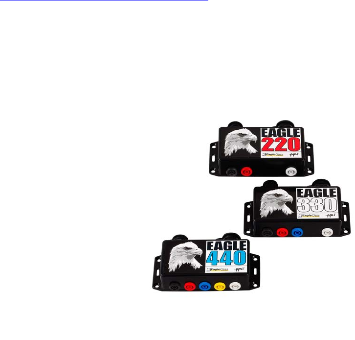
Figure 1-1: Eagle Class Recorder™

Eagle Class PQ Wireless™ Digital Recorder Manual
1.2.2 Available Models
There are several models of the Eagle Class Recorder™ that can be provided.
The label on the front cover will designate the model of the unit.
The recorder models available and their corresponding codes are:
220 – 2 Channel (two voltage and two current)
330 – 3 Channel (three voltage and three current)
440- 4 Channel (four voltage and four current)
1.2.3 Inputs
Direct hookups are fed into 2,3, or 4 voltage, 0-600vac, and 4 current inputs. The amount of current that can be monitored is
dependant on the current transducer being used. Up two eight direct inputs are available to be recorded and used with reports
and strip charts. To record an input, the input must be selected as a strip chart in WinScan™.
1.2.4 Instrument Size
The Recorder is contained in a standard 5-3/8 inch (136.5 mm) long x 2-3/8 wide (60.3 mm) high x 1-3/16 inch (30mm) high
NEMA 4x sealed box.
1.2.5 System Description
The Recorder is a system designed to measure and record AC Power parameters using state of the art digital technology.
Signal inputs from AC power connections are monitored by the system. No pen, ink or paper are required. The unit can also
be used with PalmView software running on a Palm® Personal Digital Assistant (PDA) for real time viewing of waveforms,
harmonic bar graphs, vectors, as well as numeric values.
A. Day-To-Day Use
Day-to-day operating measurements are stored and recalled instantly. Up to two MB of standard internal memory allows data
to be efficiently and economically stored and retrieved.
B. Configuration
WinScan™ software allows the user to program the unit quickly and efficiently using an Windows operating system PC.
Programming can also be done using PalmScan Software running on a Palm® PDA. It’s graphical touch screen interface
provides straight forward, user friendly configuration. Strip charts, Event parameters, and Flicker parameters can be easily
programmed. Other parameters such as Scales, CT and PT ratios, and engineering units are also easy to program.
C. Applications
A Recorder may be configured by you to record and monitor almost any voltage and current configuration. Typical
measurement applications include, but are not limited to:
• Voltage Levels
• Current Levels
• Power Factor
• Harmonics to the 51st
• Phase Rotation
• Flicker
• Power Levels
Fi
g
ure 1-2: Recorder Label
Eagle Class PQ Wireless™ Digital Recorder Manual
D. System Technology
This power Recorder is a state of the art system, designed around a microprocessor, with an executable program stored in
memory. The memory is used for data and setup storage. Bluetooth Wireless technology is also incorporated to allow users
access to data without an actual physical connection.
1.2.6 Memory
Electrically Erasable Programmable Read Only Memory (EEPROM) eliminates the need for a battery back-up. Programming
is stored in EEPROM. In the event of a power loss or system reset, the programming will be protected.
1.2.7 Clock
The Time-of-Day clock will be maintained indefinitely after loss of line power by an internal NiMH battery.
1.2.8 Recorder Construction
The Power Recorder features modular construction. All printed circuits boards are sealed for electrical isolation and protection
from the elements. Servicing should only be done by an authorized service center of PMI. The PC boards are conformal
coated and high voltage is present, servicing by unauthorized personnel can result in product or bodily damage.
1.2.9 Communications
The standard RS232 port allows you to plug the Recorder into your computer
and download the data from memory. An AC Adapter is also supplied that you
can plug into the 9 pin D shell that will power the unit for programming or
downloads. This eliminates the need to have AC voltage supplied directly to the
voltage leads.
1.3 SUPPLIED EQUIPMENT
1.3.1 Equipment Listing
The following items are supplied with your Recorder:
• the Eagle Class Recorder™
• CD Containing
• WinScan™
• This manual
• a WinScan™ Manual
• Sample files
• a serial communications cable
• a 12-volt power adapter wall transformer and cord.
• Voltage leads and probes
If any of these items are missing, call PMI immediately.
Current probes are an accessory and should be ordered as a separate line item.
1.4 ACCESSORIES
1.4.1 General
Additional functions and capabilities can be added to the Recorder as accessories. These options are briefly described in the
following paragraphs.
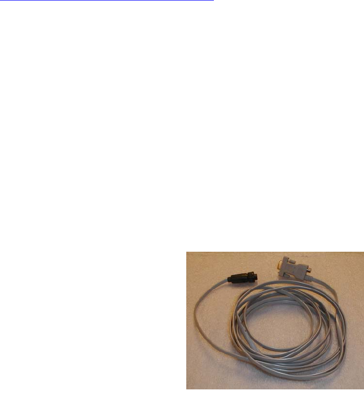
Figure 1-3: Serial Cable
Eagle Class PQ Wireless™ Digital Recorder Manual
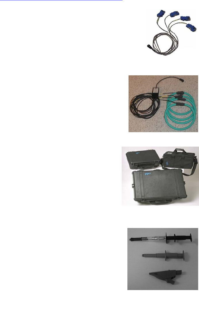
1.4.2 Current Clamps
TLAR 10 Amp current clamps are available in sets of 2,3, or 4 clamps.
1.4.3 Current Probe
PMI has a wide range of current probes (Flexible CTs) that range in circumference from
24 to 48 inches and have ranges of 100, 1000, and 5000 Amps. All our flexible current probes are powered from the unit itself
so no external batteries are needed. See figure 1-5
1.4.4 Adapters
If you have an older PMI unit we have a wide range of adapters available so you can use
your existing serial cables with your new unit(s).
1.4.5 Cases
PMI carries a wide selection of cases to carry your new or old unit, cables, CTs, and
manuals all in the same container. See figure 1-6.
1.4.6 Spare Parts List
Eagle Class Recorder™
----------------------------------------------------
Eagle Class Recorder™ Comm. Cable 90506002000
Voltage Leads
BLK test lead, straight to Right Angle 30150021
RED test lead, straight to Right Angle 30250022
BLU test lead, straight to Right Angle 30250023
YEL test lead, straight to Right Angle 30250024
WHT test lead, straight to Right Angle 30250025
Jaw Grip, 4mm 30250026
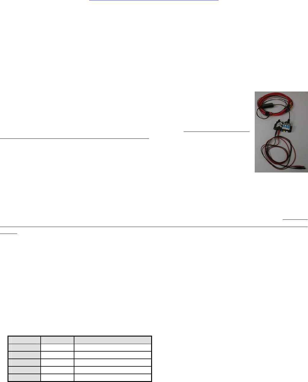
1.4.6 Voltage Clips
PMI carries a wide variety of voltage clips for your application.
Fi
g
ure 1-5: Flex CTs
Fi
g
ure 1-4: TLAR Clam
p
s
Fi
g
ure 1-6: Cases
Figure 1-7: Voltage Clips

Eagle Class PQ Wireless™ Digital Recorder Manual
1.5 SPECIFICATIONS
1.5.1 General
The Eagle Class Recorder™ specifications are shown in Table 1-1.
Table 1-1 Eagle Class Recorder™ Specifications
Eagle Class Recorder™ Recorder Specifications
Input
AC Voltage 0 to 600 VAC
AC Current 0 to 10, 100, 1000 or 5000 Amps
Sample rate: samples per second
122,800 all channels
15,360 per channel (256/cycle)
Channels
2, 3, or 4 voltage
2, 3, or 4 current
Measured Qualities
RMS Voltage (Volts)
RMS Current (Amps)
Real Power (Watts)
Apparent Power (VA)
Reactive Power (VAR)
Phase Angle (Degrees)
Power Factor (Watts/VA)
Displacement PF (cos(phase angle))
Power Usage kWh, kVARh, kVAh
Frequency Hz
Note: All quantities are measured for each cycle.
Accuracy/Resolution
(-20°F to 135°F)
Accuracy Percent of full scale
Voltage 0.33 %
(w/o probe)
Current 1.0 %
Power 1.0 %
Phase Angle 1 degree
Power Factor ±0.02
Displacement PF ±0.02
Resolution: Displayed/Internal
Voltage 1 V / 0.1 V
Current 0.1 A / 0.1 A on 10-amp
(Displays 1 A on other scales)
Power 10 W / 10 W
VAR 10VAR/10VAR
VA 10VA/10VA
Phase Angle 1° / 1°
Power Factor 0.01 / 0.01
Displacement PF 0.01 / 0.01
Power Usage 0.001 kWh/0.001 kWh
Information Storage
Memory
RAM 128K (battery-backed)
FLASH EPROM 4MB
DSP Waveform RAM up to 256K
TOTAL MEMORY 2.2 million readings
Waveform capture: Triggered
Capacity
Summary data Over 1 year
Event data 500 records
Significant change data 1000 records
Flicker data 1000 records
Stripcharts 4 hours to over 1 yr.
Voltage
Current
Power Factor
Displacement PF
Real Power
Reactive Power
Apparent Power
Phase Angle
Frequency
Retention time > 5 years
Communications
Local
Type Serial Cable
Wireless Bluetooth
Standards RS232 Compatible, Bluetooth
Data rate 1,200 to 56 kbaud
Stripchart settings 1 second to 4 hours
Significant change 1V to 8 V, in 1V steps
Flicker settings User-defined or standard
Battery voltage check Automatic
Power Requirements
Recording load < 1.5 Watts
Environmental
Operating temperature -20°F to 135°F
Shock 60Hz to 2KHz,
acceleration 25G
Vibration 10Hz to 60Hz,
amplitude 1.8mm
Physical Dimensions
Size 5.375” x 2.375” x 1.188”
Weight <1.0 lbs.
Case NEMA 4X
Power Fail Operation
The device operates with no input voltage for more than 2 hours. This allows it
to measure down to 0 volts on all channels during power outage periods.
Harmonics (optional)
Voltage Measures to the 51
st
Current Measures to the 51
st
Measures:
Magnitude
Phase
THD
Implementation of new developments and product improvements may result in specification changes in this document

Eagle Class PQ Wireless ™ Digital Recorder Manual
13
SAFETY NOTICE
This Safety Notice has been included to emphasize the danger of hazardous voltages on the INPUT
CONNECTION LEADS of your instrument. USE EXTREME CAUTION WHEN CONNECTING
OR SERVICING your instrument. Please read the entire contents of the Installation and Wiring Chapter
before attempting to connect or service your instrument.
SIGNAL INPUTS WARNING
Use extreme caution when wiring signal input connections.
Hazardous potentials may exist on signal input terminals,
which are floating, with respect to instrument ground. These
hazardous potentials may be exposed inside the instrument
case and on the Connectors of your instrument. Any voltage
potential at the signal source will exist on the instrument's
respective signal input cable.

Eagle Class PQ Wireless ™ Digital Recorder Manual
14
Connection Information Chapter 2
2.1 INTRODUCTION
2.1.1 General
This chapter provides information and procedures for connection of the Recorder. Included are handling procedures,
installation and wiring specifications, and instructions for both standard and optional equipment.
2.1.2 Manual Updates
This manual may periodically be up-dated with addendums that could affect the connection information contained in this
section. Review each addendum, if any, in the front of this manual and note changes that pertain to this section.
2.2 EQUIPMENT HANDLING
2.2.1 Initial Inspection
Exercise care when unpacking instruments from the shipping cartons. The instruments are packed in a shock-resistant foam
retainer to prevent damage during normal transit. If damage to the shipping carton is evident, ask the carrier's representative to
be present when the instrument is unpacked and refer to Limited Warranty Statement, Appendix A.
2.2.2 Unpacking Procedure
Perform the following steps to unpack your Recorder.
1. Remove the foam retainer and instrument from the shipping carton.
2. Carefully remove the instrument from the foam retainer.
A. Detected Damage
If damage is detected after unpacking the instrument, re-pack the instrument and return it to the factory as described in the
following paragraph.
2.2.3 Equipment Return
Before returning a damaged or malfunctioning instrument to the factory for repairs, a Return Authorization Number must be
obtained from the factory.
A. Return Authorization and Required Information
If the instrument is to be returned for repairs, refer to Appendix B, "Return Authorization", for complete instructions on
returning instrumentation.
2.2.4 Storage
For prolonged storage before installation, re-pack the Power Recorder in the shipping container. Cushion the Recorder with
foam molding or equivalent and store in a cool, dry area. We do not recommend storage of the Recorder for more than one
year. If longer storage time is required, contact the factory for additional storage information. See Table 2-1.

Eagle Class PQ Wireless ™ Digital Recorder Manual
15
Table 2-1: Environmental Precautions
ENVIRONMENTAL PRECAUTIONS
For optimum performance, observe the following precautions when selecting a storing environment for the Recorder.
• Avoid direct sunlight and high temperature. Operating temperature must be within -20°F to 135°F (-29 to 57°C).
• Avoid sudden temperature swings of 10°C or more.
• Avoid locations susceptible to vibration, shock, static electricity, high magnetic, electro-magnetic, or radiation fields.
• Avoid extremely dusty, dirty, or corrosive gas environments.
• Maintain adequate air circulation paths to ensure proper cooling of the unit. Ambient operating temperature should
not exceed 135°F (57°C).
Detailed Specifications are included in Chapter 1, Table 1-1,2,3.
2.3 WIRING SPECIFICATIONS AND
PROCEDURES
2.3.1 Power Requirements
The Recorder operates on voltages from 80 to 600Vac, 45-65 Hertz.
A. Recorder Operating Power Connection
Power connections to the Recorder are made by connecting the Phase A voltage signal input wiring to an appropriate signal of
80-600Vac. This will automatically charge the batteries (Batteries could take up to 14 hours to fully charge) and power up the
Recorder.
B. Batteries and power
The Recorder, when installed, powers itself from the line voltage on Channel 1. It requires less than 1.5 watts. This means the
Recorder does not contain large internal batteries that must be recharged or replaced; the Recorder can be retrieved from the
field, downloaded, and reinstalled elsewhere minutes later.
A small, AAA NiMH battery takes care of the Recorder’s minimal power needs during a power outage while the Recorder is
in record mode. This battery recharges off Channel 1 and should be replaced every three years. In addition, a Li memory
backup battery allows the Recorder to sit on a shelf for up to three years after being initialized and still be ready for
installation. Its memory can also hold recorded data for up to three years.
A 12-volt power adapter is provided to power the Recorder during downloads in the office or in the field if the Recorder has
been disconnected from the line voltage.
The AAA battery will run the unit for up to 2 hours if power is lost.
WARNING
Eagle Class PQ Wireless ™ Digital Recorder Manual
16
WHEN CONNECTING THE SIGNAL MEASURING LEADS, BE CAREFUL NOT TO TOUCH ANY OF THE
CONNECTION POINTS. LETHAL VOLTAGE AND CURRENT CAN EXIST ON ANY INPUT LEAD OR
CONNECTION POINT.
2.3.2 Installing the Recorder
This chapter explains the physical installation of the Eagle Class Recorder™. Installing the Recorder is not difficult for a
professional familiar with similar equipment, although the same care required when working with any high-voltage equipment
must be taken to complete the job safely. Please take the time to read Safety Issues, page 6, before installing the Recorder.
There are two things to connect when installing the Recorder:
1. The current probes, and
2. The alligator voltage clip leads.
Installation of the current probes depends on whether your Recorder is equipped with these items.
Please read through the next three sections before installing your Recorder. Disconnect the power from
the lines you plan to monitor until the installation is complete. Also, connect channel 1 voltage last, as
this will start the two minute countdown for recording.
A. The current probes
1. CTs
The optional TLAR current clamps connect to the nine pin connector on the side of the Recorder housing. The Recorder
automatically detects the amperage rating of the clamp connected during the two-minute initialization countdown which starts
when power is applied to the unit (see below). The Eagle Class Recorder™ Recorder can be equipped with current clamps
rated for 10A (TLAR), or Flexible CTs that have multiple ranges of 100A, 1000 or 5000A.
Once the desired clamps are properly connected to the Recorder, clamp around the line or bus you wish to monitor. The arrow
on the body of the current clamps or probes must point toward the customer (away from the utility)—in the direction of the
current. The current clamps measure amperage through induction. PMI recommends that current clamps be connected to the
Recorder whenever they are attached to a power line.
2. Installation of Flexible CT
Insert the connector of the Flex CT into the 9-pin connector on the side of the recorder. The cable branches to 2, 3 or 4
flexible clamps, each of which is snapped into a loop around each line to be monitored. The “smart box” midway on the cable
senses the induced current and processes the information for measurement. The recorder’s current range can be set using
WinScan or PMIScan.
Remember, Safety is always our primary concern.
C. The voltage clip leads
The Recorder can monitor voltage on up to four channels. Alligator clip leads are provided for each channel. These leads are
color-coded as follows:
Table 2-2: Voltage leads color coding
Channel Lead Phase
Channel 1 Black A
Channel 2 Red B
Channel 3 Blue C
Channel 4 Yellow N
Common White Common
Eagle Class PQ Wireless ™ Digital Recorder Manual
17
Attach the alligator clip leads to voltage lines in a pattern which will monitor the phases on which you wish to collect data. For
information on several ways to monitor power, see the next section, Connecting to different types of services.
The Recorder will borrow its power from the voltage on Channel 1. As soon as voltage is applied to the Channel 1 lead, the
Recorder begins a two-minute countdown. During this countdown, the Recorder will sample the voltages on each channel in
order to set the nominal voltage for the recording period. The Recorder also uses this time to detect which probes are
connected to it—see the information on current probe connections above. While the countdown continues, you may adjust
some Recorder settings. However, making a change to the Recorder settings will restart the countdown at two minutes.
During the two-minute countdown, you may exchange one type of current clamp for another (on the Eagle Class Recorder™
only). However, if you change the probes, you must restart the two-minute initialization countdown by interrupting and then
restoring power to the Recorder. If probes on an operating Recorder are exchanged with probes of a different type without re-
initializing the Recorder, the unit will retain the setting of the first probes as the operating type. This may result in incorrect
measurements.
1. Connecting to different types of services - When planning how to connect your Recorder, keep the following things in
mind:
• The banana jacks are color-coded by channel: black is Channel 1, red is Channel 2, blue is Channel 3, yellow is
Channel 4, and white is common.
• The unit is powered from the voltage between Channel 1, the black jack, and common, the white jack. For this reason,
even if you are not connecting all the input wires, Black and White must be connected.
• Be aware of the input voltage warning label on the Recorder, do not exceed the maximum input voltage. The limits
are 600 volts RMS channel to channel or channel to common for the Eagle Class Recorder™.
• You may use four-channel units to monitor five-channel systems; naturally, you will record data for only four of the
channels. Conversely, you can use a four-channel unit to monitor a single-phase system: either unplug the unused
leads, connect them in parallel so that all channels are recording the same information, or clip together to avoid noise
readings. Again, the Channel 1 leads must be connected in order to power the unit..
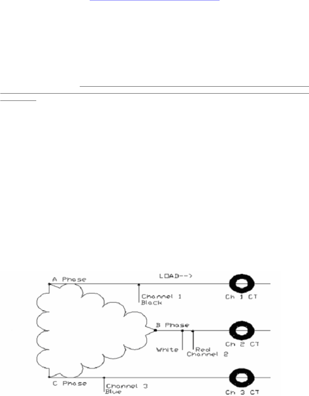
Below are diagrams showing several basic circuits and possible ways to connect them:
To connect a Recorder to monitor a delta service, connect one of the clips leads for three channels to both corners of the
phase. Clip lead for Channel 1 (black) will be connected to one corner (A). Clip the White lead to the next corner (B), and clip
the blue lead to the third corner (C).
Figure 2-1: 3 Wire Delta
Eagle Class PQ Wireless ™ Digital Recorder Manual
18
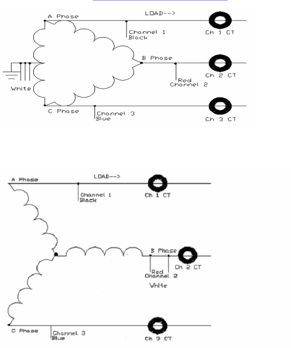
Figure 2-2: 4 Wire Delta
You can connect the clip leads phase-to-phase on a Wye service in the same manner you would when monitoring a delta
service.
Figure 2-3: 3 wire wye phase to phase
Eagle Class PQ Wireless ™ Digital Recorder Manual
19
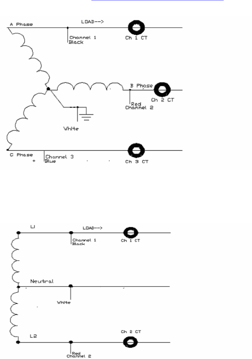
Figure 2-4: 4 wire wye
You can also connect the unit to monitor phase-to-neutral references by connecting one lead (the hot side) for each channel to
the respective phase in the circuit, and connect the white lead (common) to the neutral. In the diagram, Channel 1 is
represented by the black lead, Channel 2 (red) , and Channel 3 (blue).
Eagle Class PQ Wireless ™ Digital Recorder Manual
20
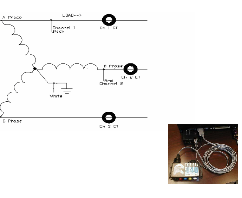
Figure 2-5: Two phase three wire
Figure 2-6: 2.5 Element Z-coil
2.3.3 Communications Port Connections
A. General
Designed into the Recorder is a Communications Port. The standard interface cable
is an RS232 Serial type used to interface with a remote terminal or computer. The
Communications Port allows you to access and manipulate the recorded information
on the Recorder.
B. RS232 Serial Cable
The RS232 Serial Cable is configured and wired to conform to the industry standard RS232 connection.
Connect the 6-pin connector of the comm. cable to your Recorder and the DB-9 (RS232) end of the cable to your computer
serial port
If the Recorder’s channel 1 voltage leads are not connected to >80Vac, connect the AC adapter provided to the power jack on
the 9 pin D shell as shown in figure 2-7. Then plug the adapter into a 120VAC outlet.
You can now use WinScan™ to download and/or set up the unit to record. Please refer to the WinScan™ manual for
instructions.
Figure 2-7: Serial Connection

Eagle Class PQ Wireless ™ Digital Recorder Manual
21
Operation Chapter 3
3.1 INTRODUCTION
3.1.1 General
This chapter contains information concerning system operation
3.2 CONTROL AND PRESENTATION
3.2.1 General
The following paragraphs are intended to familiarize you with the front panel controls and commands along with any other
day-to- day operating controls. The Recorder presents information through the display and the WinScan™ program.
3.2.2 Operator Controls
All controls are via the WinScan program or PMIScan.
3.2.3 Initialization
The Eagle must be initialized before recording data. This is done by connecting the Eagle to your PC with the Eagle serial
cable or through Bluetooth, and running WinScan. See the section \PC Communications with the Eagle" for information on
how to connect the Eagle to the PC. See the WinScan documentation for details on how to initialize a Voltage Scanner. The
Eagle may also be initialized with Palm-based PDA using the optional PMIScan software. The connection can be with the
serial cable or Bluetooth. Please see the PMIScan manual for further details.
3.2.4 LED Indicator
The unit has an LED that will indicate when the unit is counting down by blinking once per second. The LED will blink once
every six seconds when the unit is in record mode. Lastly, the LED will stay lit when communicating with the unit.
Eagle Class PQ Wireless ™ Digital Recorder Manual
22
An outline of WinScan™ Chapter 4
4.1 RETRIEVING DATA FROM THE
RECORDER
After your Recorder has finished collecting data, you need to download the
data in order to analyze it on your computer. This process can be
accomplished either over blue tooth (if your PDA or computer have a Blue
tooth device) or via a serial cable. As the data is downloaded, your computer
will save it in a file which can later be opened and analyzed. Please refer to
the WinScan™ Manual for instructions.
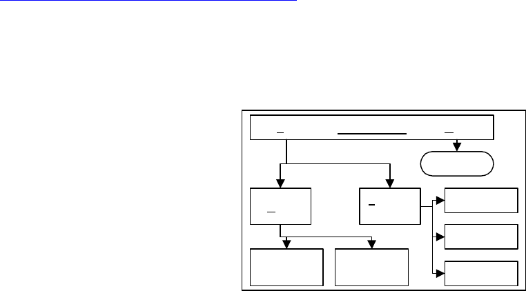
Figure 4-1 illustrates the basic structure of WinScan™. As you can see, the
main menu option H
ELP
leads to information on the program, while the
option F
ILE
leads to operations involving the Recorder, the data it collects,
and the tools needed to interpret that data.
The most useful options in the F
ILE
menu are R
ECORDER CONTROL
and L
OAD
.
As shown in the diagram, R
ECORDER CONTROL
leads to options which adjust settings on the Recorder and computer. These
options regulate the collection and retrieval of data by the Recorder.
The other important option, L
OAD
, is the gateway to creating, viewing and printing WinScan™ graphs and reports.
Familiarize yourself with all the operations of WinScan™ as described in this manual before attempting to use your Recorder.
After you are familiar with WinScan™, use the Quick Guide, in the WinScan™ Manual, as a reminder of the steps required
for certain operations. For your own protection, please take the time to read Safety Issues, before installing or operating the
Recorder.
Main Menu
Program Info
Create, view
and print
graphs
Scanner
settings
Create, view
and print
reports
Computer
settings
Load Scanner
Connect
HelpFile
Data retrieval
Figure4-2: Software outline

Eagle Class PQ Wireless ™ Digital Recorder Manual
23
Appendix 1: PC and Recorder configuration factory settings
PC
S
ETUP
OPTION FACTORY SETTING
Local: Serial Port Com 1
Local: Baud Rate 28800
Modem: Serial Port Com 2
Modem: Baud Rate Auto
Dialing Method Tone
Auto Recorder Reset Prompt
Scale Factor: Voltage 1
Scale Factor: Current 1
Auto Clock Reset On
Auto Data Save On
Stripchart Report Header Checked
R
ECORDER
S
ETUP
/I
NITIALIZE
OPTION FACTORY SETTINGS
LED Indicator Checked
Interval Recording Overwrite Checked
Ab. LED Trigger Duration 5 seconds
Interval Data Storage 100 percent
Significant Change Threshold 3 volts
Modem Ring Count 3 rings
Number of Channels 4
Rotary Switch Override Not Checked
Recording Interval 1 minute
EVENT RECORDING PARAMETERS
Nominal Voltage 120 volts
Threshold Bands 6 volts
Minimum Event Time 10 cycles
Default settings are identical for all four channels.

Eagle Class PQ Wireless ™ Digital Recorder Manual
24
FLICKER PARAMETERS—from ANSI/IEEE STANDARD 141
Period Tolerance (%) Limit
10 seconds 1 5
1 minute 1.5 10
15 minutes 2 10
30 minutes 2.5 10
1 hour 3 10
4 hours 3.5 10
8 hours 4 10
12 hours 5 10
24 hours 6 10
Default settings are identical for all four channels.
ABNORMAL LED INDICATORS
Nominal Low Range High Range
Standard: 120 6 12
Standard: 208 10 20
Standard: 240 12 24
Standard: 277 13 27
Standard: 480 24 48
Custom: 106 5 10
Custom: 203 11 23
Default settings are identical for all four channels.

Eagle Class PQ Wireless ™ Digital Recorder Manual
25
Appendix 2: Warranty Clause
Power Monitors Inc. (PMI) warrants each new product manufactured and sold to be free from defects in material, workmanship, and
construction, and that when used in accordance with this manual will perform to applicable specifications for a period of one year after
shipment.
If examination by PMI discloses that the product has been defective, then our obligation is limited to repair or replacement, at our option, of
the defective unit or its components. PMI is not responsible for products which have been subject to misuse, alteration, accident, or for
repairs not performed by PMI.
The foregoing warranty constitutes PMI’s sole liability, and is in lieu of any other warranty of merchantability or fitness. PMI shall not be
responsible for any incidental or consequential damages arising from any breach of warranty.
Equipment Return
If any PMI product requires repair or is defective, call PMI at (800) 296-4120 before shipping the unit to PMI. If the problem cannot be
resolved over the phone, PMI will issue a return authorization number. For prompt service, all shipments to PMI must include:
1. Billing and shipping address for return of equipment.
2. The name and telephone number of whom to contact for further information.
3. A description of the problem or the work required.
4. A list of the enclosed items and serial numbers.
5. A return authorization number.
6. If possible, a copy of the original invoice.
Equipment returned to PMI must be shipped with freight charges prepaid. After repair, PMI will return equipment F.O.B. factory. If
equipment is repaired under warranty obligation, freight charges (excluding air freight or premium services) will be refunded or credited to
the customer’s account. Return equipment to:
Power Monitors Inc.
1661 Virginia Avenue
Harrisonburg, VA. 22802 USA
Attention: Repair Department

Eagle Class PQ Wireless ™ Digital Recorder Manual
26
Appendix 3: Troubleshooting
Symptom Possible Solution
Unit indicates negative real power, wrong phase
angle Voltage leads on this channel may be reversed;
also may be due to reversed current CT connection
Unit indicates negative real power, wrong phase
angle
Current CT may be reversed, clamped around
conductor in wrong direction; also may be due to
reversed voltage leads.
Current clamp "buzzes" when connected around
conductor.
Clamp jaws not closing completely, or dirt/rust on
surface of metal jaws; Clean contacts and retry.
A
lso try a different CT
Unit will not communicate
Make certain that Local and Modem port are set to
different com #s, and that Palm Pilot HotSync
Manager is turned off!
Unit will not communicate
Insure the serial port is correct and serial cables
are correct. Retry at different baud rates. Turn off
power management (or power saving) in the
Windows control panel and the bios. Retry.
Unit will not download data
Try Different baud Rates, Bring up the task
manager in Windows and "end task" for all
programs except WinScan™, Systray, and
Explorer, Retry.
Recorder downloads to 99% and gives serial
comm error Contact PMI for assistance and/or WinScan™
upgrade
Strip chart shows very high or wildly fluctuating,
unrealistic readings or spikes on V and I Contact PMI for an upgrade and retry.
Waveform capture graph does not plot time axis
correctly; 50Hz sinusoidal waveform plotted with
60Hz period.
Contact PMI for WinScan™ Upgrade
Waveform capture graph does not plot time axis
correctly; 50Hz sinusoidal waveform plotted with
60Hz period. Contact PMI for WinScan™ Upgrade
Some current channels do not work on flex CT's. Possible wires in flex CT are cut or nicked. Try a
different set or Contact PMI for Evaluation
Eagle Class PQ Wireless ™ Digital Recorder Manual
27
Appendix 4: Eagle Class Recorder™ Formulas

Eagle Class PQ Wireless ™ Digital Recorder Manual
28

Eagle Class PQ Wireless ™ Digital Recorder Manual
29
Eagle Class PQ Wireless ™ Digital Recorder Manual
30

Eagle Class PQ Wireless ™ Digital Recorder Manual
31
APPENDIX 5: Regulatory Information
U.S. FCC Part 15 and Industry Canada RSS 210 Statements
This device complies with part 15 of the FCC Rules. Operation is subject to the following two conditions: (1) This device may
not cause harmful interference, and (2) this device must accept any interference received, including interference that may cause
undesired operation.
The letters “IC” have no other meaning or purpose than to identify the Industry Canada certification number/registration
number.
FCC Warning
Changes or modifications not expressly approved by Power Monitors Inc. could void the user’s authority to operate this
equipment.
Safety Warning
In order to ensure user safety and maintain a water tight, pollution free internal environment, this product, including the
enclosure lid, has been sealed shut at the factory. There are no user serviceable parts inside. Any attempt to open the sealed lid
could pose a safety hazard, compromise the watertight integrity of the enclosure, and may permanently alter the required
electrical isolation between high voltage circuitry and the user. The AC line fuse, MOV, and the internal batteries (memory
backup Lithium battery, and the NIMH ride-through battery) are replaceable, but should only be performed by PMI Inc. to
ensure continued product safety and performance.

Eagle Class PQ Wireless ™ Digital Recorder Manual
32
INDEX
: 3 wire wye, 19
: Two phase three wire, 20
2.5 Element Z-coiL, 20
3 wire wye, 19
4 Wire Delta, 18
4 wire wye, 19
AC Adapter, 10
Adapters, 11
Alligator clips. See Voltage clip leads
Cases, 11
Clock, 10, 24
Countdown, initialization, 17
Current Clamps, 11
Current Probe, 11
Current probes, 7, 16
Precautions when installing, 16, 17
Default settings. See Factory settings
Delta circuit, 17
ENVIRONMENTAL PRECAUTIONS, 15
Factory settings, 24
Inputs, 9
LCD, 8, 10, 17
Models, 9
modem, 16
Palm, 9
PalmScan, 9
Power adapter, 15
Power Monitors Inc.
Address, 26
Phone number, 1
Warranty, 26
Power Requirements, 12, 15
RS232 Serial Cable, 21
SAFETY, 6, 13
Safety Issues, 6
Scanner
Batteries, 15
Installing, 16
Memory, 12
Power, 15, 17
Retrieving data from, 23
Specifications, 12
S
CANNER
C
ONNECT
, 23
Specifications, 15
Storage, 12, 14, 24
Two-minute countdown. See Countdown,
initialization
Voltage clip leads, 16
Color-coding, 16
Voltage leads, 16
WARNING, 6, 13, 15
WinScan, 9
Wye circuit, 18